Embed Size (px)
Citation preview
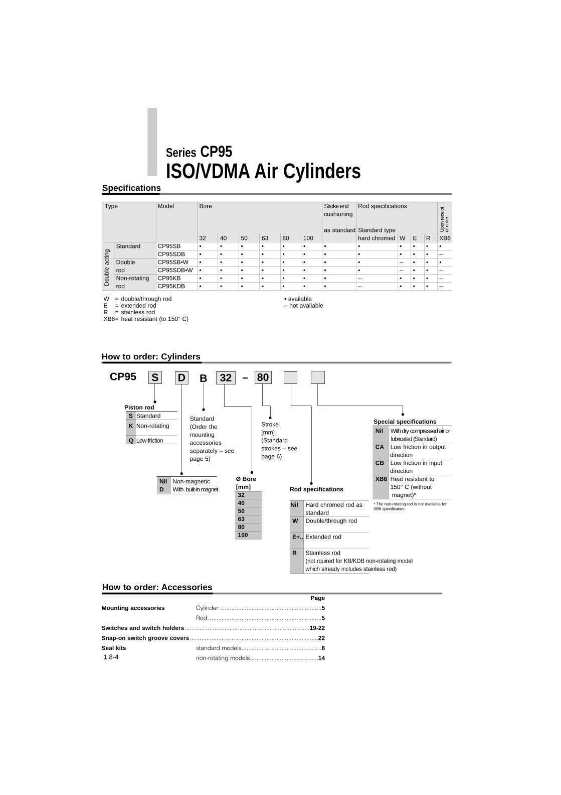
Type Model Bore Stroke end Rod specifications cushioning
as standard Standard type32 40 50 63 80 100 hard chromed W E R XB6
Standard CP95SB • • • • • • • • • • • •CP95SDB • • • • • • • • • • • –
Double CP95SB•W • • • • • • • • – • • •rod CP95SDB•W • • • • • • • • – • • –Non-rotating CP95KB • • • • • • • – • • • –rod CP95KDB • • • • • • • – • • • –D
oubl
e ac
ting
Upo
n re
ceip
t of
ord
er
W = double/through rodE = extended rodR = stainless rodXB6= heat resistant (to 150° C)
• available– not available
S Standard
K Non-rotating
Q Low friction
Nil Non-magneticD With built-in magnet
Nil With dry compressed air orlubricated (Standard)
CA Low friction in output direction
CB Low friction in inputdirection
XB6 Heat resistant to150° C (without magnet)*
Nil Hard chromed rod asstandard
W Double/through rod
E+.. Extended rod
R Stainless rod(not rquired for KB/KDB non-rotating model which already includes stainless rod)
Ø Bore[mm]3240506380100
CP95 S –
Piston rod
Stroke[mm](Standardstrokes – seepage 6)
Rod specifications
D 8032B
* The non-rotating rod is not available forXB6 specification.
Series CP95ISO/VDMA Air Cylinders
Specifications
How to order: Cylinders
Standard(Order themountingaccessoriesseparately – seepage 5)
Special specifications
How to order: AccessoriesPage
Mounting accessories Cylinder .............................................................5
Rod ....................................................................5
Switches and switch holders...........................................................................19-22
Snap-on switch groove covers .............................................................................22
Seal kits standard models................................................8
non-rotating models.........................................141.8-4
1.8-5
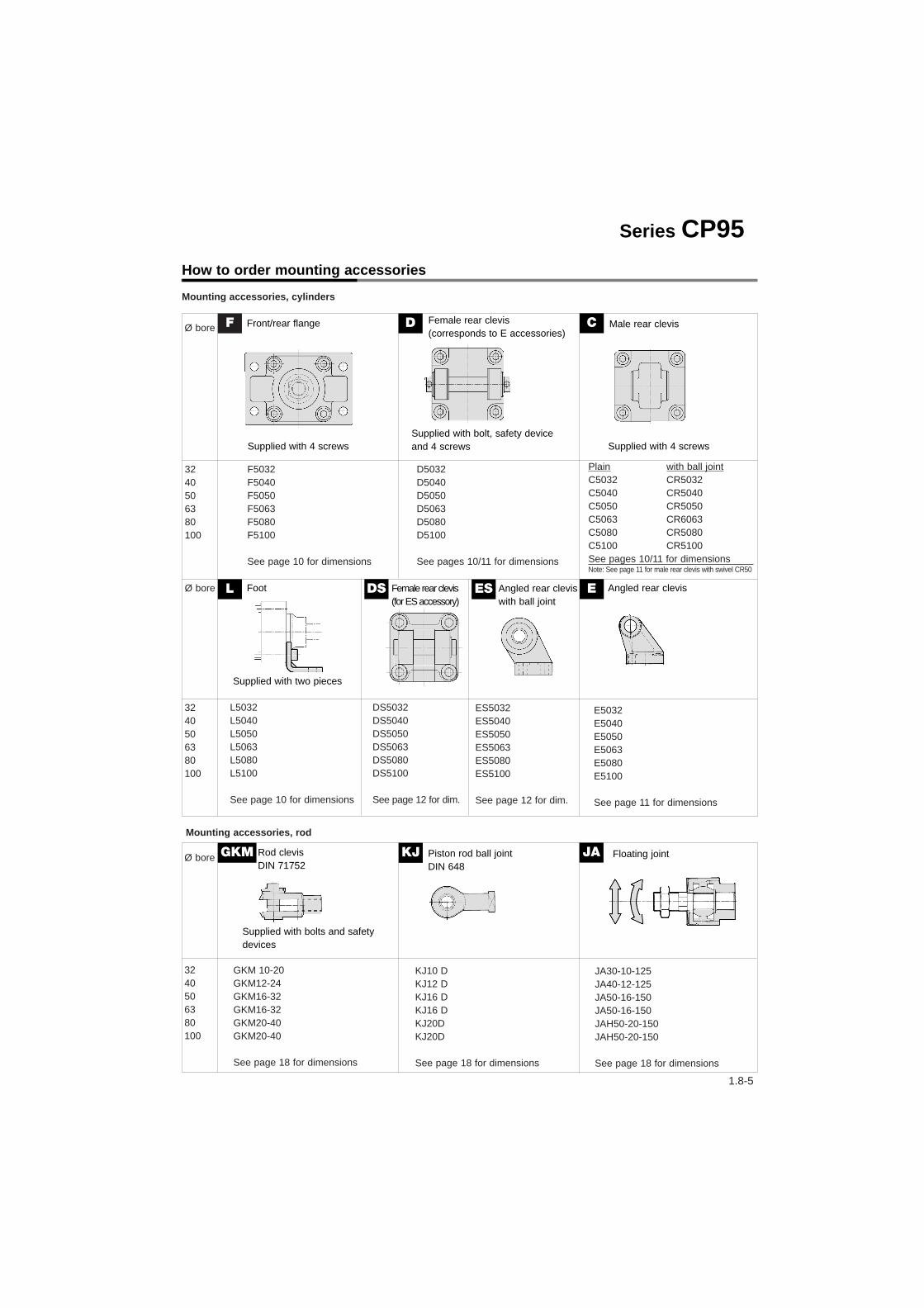
Mounting accessories, cylinders
Mounting accessories, rod
Ø bore
3240506380100
Ø bore
3240506380100
Ø bore
3240506380100
F5032F5040F5050F5063F5080F5100
See page 10 for dimensions
D5032D5040D5050D5063D5080D5100
See pages 10/11 for dimensions
Plain with ball jointC5032 CR5032C5040 CR5040C5050 CR5050C5063 CR6063C5080 CR5080C5100 CR5100See pages 10/11 for dimensionsNote: See page 11 for male rear clevis with swivel CR50
L5032L5040L5050L5063L5080L5100
See page 10 for dimensions
E5032E5040E5050E5063E5080E5100
See page 11 for dimensions
DS5032DS5040DS5050DS5063DS5080DS5100
See page 12 for dim.
ES5032ES5040ES5050ES5063ES5080ES5100
See page 12 for dim.
GKM 10-20GKM12-24GKM16-32GKM16-32GKM20-40GKM20-40
See page 18 for dimensions
KJ10 DKJ12 DKJ16 DKJ16 DKJ20DKJ20D
See page 18 for dimensions
JA30-10-125JA40-12-125JA50-16-150JA50-16-150JAH50-20-150JAH50-20-150
See page 18 for dimensions
F D C
L DS ES E
GKM KJ JA
Front/rear flange
Supplied with 4 screws
Female rear clevis(corresponds to E accessories)
Supplied with bolt, safety deviceand 4 screws
Male rear clevis
Supplied with 4 screws
Foot
Supplied with two pieces
Female rear clevis(for ES accessory)
Angled rear cleviswith ball joint
Angled rear clevis
Rod clevisDIN 71752
Piston rod ball jointDIN 648
Floating joint
Supplied with bolts and safetydevices
Series CP95How to order mounting accessories

1.8-6
• Conforms to VDMA 24 562 (parts 1 and 2),ISO 6431 and CETOP standards
• Combines lightweight profile barrel designwith enclosed tie rods for extra strength
• Unique seal system ensures efficientperformance and long life
• Fully adjustable cushioning at end of stroke
• Magnetic proximity sensing
• Superior cushioning performance andkinetic energy absorption
Bore [mm] 32 40 50 63 80 100Type Non-lube typeAction Double acting single rod Fluid Compressed air filtered to <10 µm,lubricated or non lubricated (dry air)Proof pressure 1.5MPa {15.3kgf/cm2}Maximum operating pressure 1.0MPa {10.2kgf/cm2}Minimum operating pressure 0.05MPa {0.5kgf/cm2}
Piston force Up to 7500NPiston rod Hard chromed steel (25µm finish)Lubrication Not required (non-lube)Rod diameter [mm] 12 16 20 20 25 30Piston rod thread M10x1.25 M12x1.25 M16x1.5 M16x1.5 M20x1.5 M20x1.5Ports G1/8 G1/4 G1/4 G3/8 G3/8 G1/2Cushioning stroke [mm] 19 19 24 24 30 30Mounting position AnyStandard strokes 25, 50, 80, 100, 125, 160, 200, 250, 320, 400, 500, 600, 700, 800(DIN ISO 4393) [mm] Other stroke lengths in accordance with ISO497 R 10Stroke tolerance [mm] <250mm: + 1.0/-0mm, <1000mm: + 1.4/-0mm, <1500mm: + 1.8/-0mmWorking pressure [MPa] 0.05 - 1.0Fluid and ambient temperature [°C] -10°C to +60°C, -10°C to +70°C without magnetPiston speed [mm/s] 50 - 1000
Technical specifications
Ø Standard stroke Max.Bore stroke32 25, 50, 80, 100, 125, 160, 200, 250, 320, 400, 450, 500 70040 25, 50, 80, 100, 125, 160, 200, 250, 320, 400, 450, 500 80050 25, 50, 80, 100, 125, 160, 200, 250, 320, 400, 450, 500, 600 120063 25, 50, 80, 100, 125, 160, 200, 250, 320, 400, 450, 500, 600 120080 25, 50, 80, 100, 125, 160, 200, 250, 320, 400, 450, 500, 600, 700, 800 1400100 25, 50, 80, 100, 125, 160, 200, 250, 320, 400, 450, 500, 600, 700, 800 1500
Standard strokes
ISO/VDMA Air Cylinder
Series CP95 VDMADouble acting with end of stroke cushioning Ø32 - Ø100
[mm]
Note: Intermediate strokes are also available

1.8-7
Series CP95
Ø Bore Ø Rod diam. Operating Piston area Working pressure [MPa][mm] [mm] direction [mm2] 0.2 0.3 0.4 0.5 0.6 0.7 0.8 0.9 1032 12 OUT 804 161 241 322 402 482 563 643 724 804
IN 691 138 207 276 346 415 484 553 622 69140 16 OUT 1257 251 377 503 629 754 880 1006 1131 1257
IN 1056 211 317 422 528 634 739 845 950 105650 20 OUT 1963 393 589 785 982 1178 1374 1570 1767 1963
IN 1649 330 495 660 825 989 1154 1319 1484 164963 20 OUT 3117 623 935 1247 1559 1870 2182 2494 2805 3117
IN 2803 561 841 1121 1402 1682 1862 2242 2523 280380 25 OUT 5027 1005 1508 2011 2514 3016 3519 4022 4524 5027
IN 4536 907 1361 1814 2268 2722 3175 3629 4082 4536100 30 OUT 7854 1571 2356 3142 3927 4712 5498 6283 7069 7854
IN 7147 1429 2144 2859 3574 4288 5003 5718 6432 7147
Theoretical output table [N]
Ø Bore Mounting type 32 40 50 63 80 100 Basic type B 0.59 0.87 1.44 2.00 3.37 4.45Foot L 0.16 0.20 0.38 0.46 0.89 1.09
Basic weight Front/rear flange F 0.20 0.23 0.47 0.58 1.30 1.81Male rear clevis C 0.16 0.23 0.37 0.60 1.07 1.73Female rear clevis D 0.20 0.32 0.45 0.71 1.28 2.11Angled rear clevis E 0.16 0.22 0.42 0.52 0.94 1.40Female rear clevis DS 0.17 0.27 0.45 0.64 1.37 2.05Spherical bearing ES 0.18 0.27 0.46 0.55 0.97 1.33
Additional weight 0.11 0.17 0.28 0.40 0.67 0.89per 50 mm strokeAccessories Piston rod ball joint KJ 0.15 0.23 0.26 0.26 0.60 0.83
Rod clevis GKM 0.22 0.37 0.43 0.43 0.87 1.27Floating joint JA 0.015 0.20 0.26 0.26 0.9 0.9
Weight table
Weight calculation methodExample: CP95S32-100
(basic Ø32, 100st)• Basic weight . . . . .0.59kg
(Standard Ø32)• Additional weight . .0.11kg/50mm stroke• Cylinder stroke . . .100st
Cylinder weight = 0.59+(0.11 x 100/50)=0.81kg
Note: Theoretical output OUT [N] =Pressure [MPa] x Piston area [mm2]
Ø Cushioning AbsorbableBore stroke [mm] kinetic[mm] energy [J]32 19 2.240 19 3.450 24 5.963 24 1180 30 20100 30 29
Kinetic energy absorbable by air cushion mechanism
At the stroke end, when stopping a largeamount of kinetic energy generated by alarge load and high speed operation,compression of air is used to absorb theimpact without transmitting vibration tothe surroundings. The purpose of an aircushion is not to reduce the speed of apiston as it nears the stroke end. Thekinetic energy of a load can be foundusing the following formula:
Example: Find the rod end load limit when a ø63 air cylinder isoperated at a maximum drive speed of 500mm/s. Extend upwardfrom 500mm/s on the horizontal axis of the graph to the intersectionpoint with the line for a tube bore of 63mm, and then extend lefwardfrom this point to find the load of 80kg.
Moveable mass at various piston speeds
E: Kinetic energy [J = Nm]m: Load weight [kg]v: Piston speed [m/s]
12E = m • v2
100 300 1000 2000500
900
500
300
200
10080
50
30
20
10
ø32
ø40
ø100
ø80
ø63
ø50
5
Maximum piston speed [mm/s]
Load
[kg]
[kg]
OUT IN
Note: v is final velocity which is 1.4 • averagevelocity.
If the kinetic energy obtained is nogreater than the absorbable kineticenergy shown in the table above, thelife of the cushion seal should be 10million cycles or more.

1.8-8
Series CP95
No. Description Material� Head cover Die-cast aluminum� End cover Die-cast aluminum� Cylinder tube Die-cast aluminum� Piston rod Hard chromed steel C45� Piston Die-cast aluminum� Cushion ring Brass� Tie rod Steel, zinc chromate plated Tie rod nut Steel, zinc chromate plated Rod end nut Steel, zinc chromate plated� Snap ring Steel nickel plated� Bushing Lead-bronze casting Cushion valve Steel, zinc chromate plated� Cushion seal Elastomer� Wear ring Antifriction material� Piston seal NBR� Rod seal NBR� Cylinder tube gasket NBR� Cushioning valve seal NBR� Piston/rod gasket NBR� Magnet ring
Replacement parts: Seal kitsØ32 includes order No. from � to �, Ø40 - Ø100 includes from to �
Ø Order No.32 CS95-3240 CS95-4050 CS95-5063 CS95-6380 CS95-80100 CS95-100
Parts list
� � �� �� �� � � � � �
�
A
A' Sectional view A-A'
� �
�
Construction
Ø L1 L2 FB1 allowable32 62.5 34.5 + st 80 N40 74.0 39.0 + st 125 N50 76.0 44.5 + st 195 N63 91.0 44.5 + st 310 N80 93.0 53.0 + st 500 N100 104.0 57.5 + st 785 N
L2L1
FB1 = WS (1+ ) ≤ FB allowable
Maximum allowable radial loads
Stroke
e.g. 63mm bore, 100mm stroke, Ws = 20N
Ws = (2kgs) 20N
144.591
FB1 = 20 (1+ ) = 51.76N
FB1 = 51.76N ≤ 310N (from table)
Therefore, side load is allowable

1.8-9
Ø Bore AM ØB ØD EE PL RT I12 KK SW G BG I8
32 22 30 12 G1/8 13 M6 6 M10x1.25 10 27 16 9440 24 35 16 G1/4 14 M6 6.5 M12x1.25 13 27 16 10550 32 40 20 G1/4 15.5 M8 8 M16x1.5 16 31.5 16 10663 32 45 20 G3/8 16.5 M8 8 M16x1.5 16 31.5 16 12180 40 45 25 G3/8 19 M10 10 M20x1.5 21 38 16 128100 40 55 30 G1/2 19 M10 10 M20x1.5 21 38 16 138
VD VA WA WB WH ZZ ZY �E �R I2 I9
4 4 4 6.5 26 146 190 46 32.5 15 44 4 4 9 30 163 213 52 38 17 46 4 5 10.5 37 179 244 65 46.5 24 56 4 9 12 37 194 259 75 56.5 24 58 4 11.5 14 46 218 300 95 72 30 58 4 17 15 51 233 320 114 89 32 5
CP95S�BØ-stroke
CP95S�BØ-stroke W
Dimensions - standard specifications [mm]
STROKE
STROKE
STROKE
STROKE
Stroke endcushioning
STROKE
ISO/VDMA Air Cylinders Series CP95

1.8-10
Series CP95
Mounting type L
Mounting type F
Mounting type C Mounting type D
Rear mounting
Front mounting
Dimensions – mounting accessories L, F, C and D [mm]
Ø Bore
STROKE
STROKE
STROKE
STROKE
1.8-11
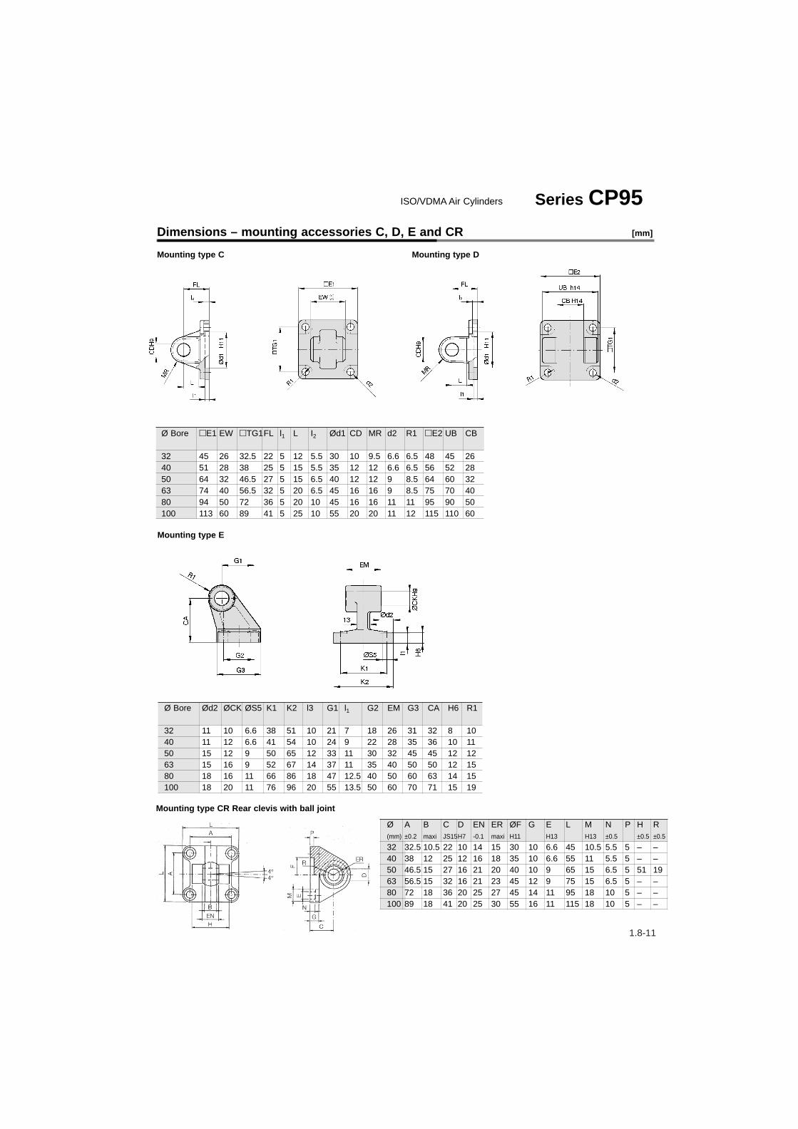
Ø Bore �E1 EW �TG1FL l1 L I2 Ød1 CD MR d2 R1 �E2 UB CB
32 45 26 32.5 22 5 12 5.5 30 10 9.5 6.6 6.5 48 45 2640 51 28 38 25 5 15 5.5 35 12 12 6.6 6.5 56 52 2850 64 32 46.5 27 5 15 6.5 40 12 12 9 8.5 64 60 3263 74 40 56.5 32 5 20 6.5 45 16 16 9 8.5 75 70 4080 94 50 72 36 5 20 10 45 16 16 11 11 95 90 50100 113 60 89 41 5 25 10 55 20 20 11 12 115 110 60
Ø Bore Ød2 ØCK ØS5 K1 K2 l3 G1 l1 G2 EM G3 CA H6 R1
32 11 10 6.6 38 51 10 21 7 18 26 31 32 8 1040 11 12 6.6 41 54 10 24 9 22 28 35 36 10 1150 15 12 9 50 65 12 33 11 30 32 45 45 12 1263 15 16 9 52 67 14 37 11 35 40 50 50 12 1580 18 16 11 66 86 18 47 12.5 40 50 60 63 14 15100 18 20 11 76 96 20 55 13.5 50 60 70 71 15 19
Mounting type E
Mounting type C Mounting type D
Dimensions – mounting accessories C, D, E and CR [mm]
Mounting type CR Rear clevis with ball joint
ISO/VDMA Air Cylinders Series CP95
Ø A B C D EN ER ØF G E L M N P H R(mm) ±0.2 maxi JS15H7 -0.1 maxi H11 H13 H13 ±0.5 ±0.5 ±0.5
32 32.5 10.5 22 10 14 15 30 10 6.6 45 10.5 5.5 5 – –40 38 12 25 12 16 18 35 10 6.6 55 11 5.5 5 – –50 46.5 15 27 16 21 20 40 10 9 65 15 6.5 5 51 1963 56.5 15 32 16 21 23 45 12 9 75 15 6.5 5 – –80 72 18 36 20 25 27 45 14 11 95 18 10 5 – –100 89 18 41 20 25 30 55 16 11 115 18 10 5 – –

1.8-12
Mounting type DS
Mounting type ES
Ø Bore �E B1 B2 B3 �TG1 T L1 L3 I1 I2 FL H Ød1 Ød2 Ød3 CN XD
32 45 14 34 3.3 32.5 3 11.5 41 5 5.5 22 10 30 10.5 6.6 10 14240 55 16 40 4.3 38 4 12 48 5 5.5 25 10 35 11 6.6 12 16050 65 21 45 4.3 46.5 4 14 54 5 6.5 27 10 40 15 9 16 17063 75 21 51 4.3 56.5 4 14 60 5 6.5 32 12 45 15 9 16 19080 95 25 65 4.3 72 4 16 75 5 10 36 16 45 18 11 20 210100 115 25 75 6.3 89 4 16 85 5 10 41 16 55 18 11 20 230
Ø Bore Ød3 ØCN ØS5 K1 K2 I2 G1 G2 G3 EN EU CH H6 ER
32 11 10 6.6 38 51 8.5 21 18 31 14 10.5 32 10 1540 11 12 6.6 41 54 8.5 24 22 35 16 12 36 10 1850 15 16 9 50 65 10.5 33 30 45 21 15 45 12 2063 15 16 9 52 67 10.5 37 35 50 21 15 50 12 2380 18 20 11 66 86 11.5 47 40 60 25 18 63 14 27100 18 20 11 76 96 12.5 55 50 70 25 18 71 15 30
Dimensions – mounting accessories DS and ES [mm]
Series CP95
Piston rod ball joint toDIN 648K
STROKE