Embed Size (px)
Citation preview

CP 243-1 communications processor for Industrial Ethernet and information technology
____________________________________________________________________________________________________________________________________________
Preface
Introduction
1
Features and functions
2
Installation and commissioning
3
Configuration
4
Programming
5
Diagnostics
6
Appendix A: Technical specifications
A
Appendix B: Example
B
Appendix C - Timeouts
C
Appendix D - Compatibility
D
SIMATIC NET
CP 243-1 communications processor for Industrial Ethernet and information technology Operating Instructions
01/2010 C79000-G8976-C244-01

Legal information Legal information Warning notice system
This manual contains notices you have to observe in order to ensure your personal safety, as well as to prevent damage to property. The notices referring to your personal safety are highlighted in the manual by a safety alert symbol, notices referring only to property damage have no safety alert symbol. These notices shown below are graded according to the degree of danger.
DANGER indicates that death or severe personal injury will result if proper precautions are not taken.
WARNING indicates that death or severe personal injury may result if proper precautions are not taken.
CAUTION with a safety alert symbol, indicates that minor personal injury can result if proper precautions are not taken.
CAUTION without a safety alert symbol, indicates that property damage can result if proper precautions are not taken.
NOTICE indicates that an unintended result or situation can occur if the corresponding information is not taken into account.
If more than one degree of danger is present, the warning notice representing the highest degree of danger will be used. A notice warning of injury to persons with a safety alert symbol may also include a warning relating to property damage.
Qualified Personnel The product/system described in this documentation may be operated only by personnel qualified for the specific task in accordance with the relevant documentation for the specific task, in particular its warning notices and safety instructions. Qualified personnel are those who, based on their training and experience, are capable of identifying risks and avoiding potential hazards when working with these products/systems.
Proper use of Siemens products Note the following:
WARNING Siemens products may only be used for the applications described in the catalog and in the relevant technical documentation. If products and components from other manufacturers are used, these must be recommended or approved by Siemens. Proper transport, storage, installation, assembly, commissioning, operation and maintenance are required to ensure that the products operate safely and without any problems. The permissible ambient conditions must be adhered to. The information in the relevant documentation must be observed.
Trademarks All names identified by ® are registered trademarks of the Siemens AG. The remaining trademarks in this publication may be trademarks whose use by third parties for their own purposes could violate the rights of the owner.
Disclaimer of Liability We have reviewed the contents of this publication to ensure consistency with the hardware and software described. Since variance cannot be precluded entirely, we cannot guarantee full consistency. However, the information in this publication is reviewed regularly and any necessary corrections are included in subsequent editions.
Siemens AG Industry Sector Postfach 48 48 90026 NÜRNBERG GERMANY
Ordernumber: C79000-G8976-C244 Ⓟ 01/2010
Copyright © Siemens AG 2010. Technical data subject to change

CP 243-1 communications processor for Industrial Ethernet and information technology Operating Instructions, 01/2010, C79000-G8976-C244-01 3
Preface
Purpose of the manual This manual supports you when you use the communications processor CP 243-1. It provides you with information on how to communicate with this communications processor via Industrial Ethernet and how to use the Information Technology (IT) functions.
Requirements To be able to understand how the CP 243-1 works, you should be familiar with this manual and the "SIMATIC S7-200 Automation System" manual. You will find the document on the Internet under the following entry ID: 1109582 (http://support.automation.siemens.com/WW/view/en/1109582) You also require a basic understanding of TCP/IP, FTP, e-mail, HTML, Web browsers and Java.
Target group This manual is intended for engineers, programmers, commissioning personnel and maintenance personnel with a general knowledge of automation and communications systems as well as operator control and monitoring systems.
Sample program This manual contains a sample program that will help you to program the CP 243-1. This sample program can be run on an S7-200 CPU, type 224. If you want to run this sample program on another S7-200 CPU, you may need to adjust the configuration for the sample program. The CP 243-1 cannot be operated with every S7-200 CPU.
Address label: MAC address The CP 243-1 ships with a fixed MAC address. You will find the MAC address beneath the top cover of the device.
MLFB (order) number, components of the product Product name MLFB (order number) Components of the product CP 243-1 6GK7243-1EX01-0XE0 CP, documentation on
CD-ROM


CP 243-1 communications processor for Industrial Ethernet and information technology Operating Instructions, 01/2010, C79000-G8976-C244-01 5
Table of contents
Preface ...................................................................................................................................................... 3 1 Introduction................................................................................................................................................ 7 2 Features and functions .............................................................................................................................. 9
2.1 Overview ........................................................................................................................................9 2.2 S7 communication via Industrial Ethernet ...................................................................................10 2.2.1 Preliminary overview....................................................................................................................10 2.2.2 Types of communication ..............................................................................................................11 2.2.3 Communications partners ............................................................................................................11 2.3 IT communication.........................................................................................................................14 2.3.1 Preliminary overview....................................................................................................................14 2.3.2 Types of communication ..............................................................................................................15 2.3.3 E-mails .........................................................................................................................................15 2.3.4 FTP server ...................................................................................................................................18 2.3.5 FTP client .....................................................................................................................................20 2.3.6 HTTP server.................................................................................................................................22 2.4 File syste ......................................................................................................................................26 2.5 User administration ......................................................................................................................28 2.6 Safety ...........................................................................................................................................29 2.6.1 Configuration................................................................................................................................29 2.6.2 Data security ................................................................................................................................30 2.6.3 Reliability of communication ........................................................................................................31 2.7 Connectors...................................................................................................................................32 2.7.1 Connectors...................................................................................................................................32 2.8 Codes: Front LEDs ......................................................................................................................33 2.8.1 Codes: Front LEDs ......................................................................................................................33
3 Installation and commissioning ................................................................................................................ 35 3.1 Important notes on installation and commissioning.....................................................................35 3.2 Installation and commissioning....................................................................................................36 3.3 Dimensions for installation in a switching panel ..........................................................................39 3.4 Dimensions for installation on a DIN rail ......................................................................................39 3.5 Installation in a panel ...................................................................................................................40 3.5.1 Installation in a panel ...................................................................................................................40 3.6 Installation on a standard DIN rail................................................................................................41 3.7 Replacing a module .....................................................................................................................42 3.7.1 Replacing a module .....................................................................................................................42 3.8 Uninstalling the CP 243-1 ............................................................................................................42
4 Configuration ........................................................................................................................................... 43 4.1 Configuration options ...................................................................................................................43

Table of contents
CP 243-1 communications processor for Industrial Ethernet and information technology 6 Operating Instructions, 01/2010, C79000-G8976-C244-01
4.2 Value ranges of the configuration data ....................................................................................... 44 4.2.1 IP addresses ............................................................................................................................... 44 4.2.2 Subnet mask ............................................................................................................................... 44 4.2.3 TSAPs ......................................................................................................................................... 45 4.2.4 Ports ............................................................................................................................................ 45 4.2.5 E-mail tags .................................................................................................................................. 45 4.3 Configuring a CP 243-1 with STEP 7.......................................................................................... 47 4.3.1 Basic configurations .................................................................................................................... 48 4.3.2 Configuration of user administration ........................................................................................... 51 4.3.3 Configuration of the e-mail functions .......................................................................................... 51 4.3.4 Configuring the FTP functions .................................................................................................... 53 4.3.5 Completing configuration ............................................................................................................ 54 4.4 Other options when configuring a CP 243-1............................................................................... 54 4.4.1 Occupied special memory (SM area).......................................................................................... 55 4.4.2 Structure of the configuration data block (CDB) ......................................................................... 56 4.4.3 Structure of the network parameter block (NPB) ........................................................................ 61 4.4.4 Structure of the network data block (NDB) ................................................................................. 61 4.4.5 Structure of the Internet data block (IDB) ................................................................................... 63 4.4.6 Structure of the configuration file for user administration (.udb file) ........................................... 65 4.4.7 Structure of the configuration file for the e-mail client (.edb file)................................................. 68 4.4.8 Structure of the configuration file for the e-mail client (.adb file)................................................. 70 4.4.9 Structure of the configuration file for the FTP client (.fdb file)..................................................... 73 4.5 Configuration of a communications partner with STEP 7 ........................................................... 77 4.6 Reaction of the CP 243-1 to configuration errors ....................................................................... 79
5 Programming ........................................................................................................................................... 81 5.1 ETHx_CTRL ................................................................................................................................ 82 5.2 ETHx_CFG.................................................................................................................................. 84 5.2.1 ETHx_CFG.................................................................................................................................. 84 5.3 ETHx_XFR .................................................................................................................................. 85 5.4 ETHx_EMAIL............................................................................................................................... 87 5.5 ETHx_FTPC ................................................................................................................................ 89
6 Diagnostics .............................................................................................................................................. 93 6.1 Diagnostic options....................................................................................................................... 93 6.2 Error messages of the CP 243-1 ................................................................................................ 96 6.2.1 Error messages in byte format.................................................................................................... 98 6.2.2 Error messages in word format................................................................................................. 102 6.2.3 Error messages of the test mechanism for e-mails .................................................................. 104
A Appendix A: Technical specifications..................................................................................................... 107 B Appendix B: Example ............................................................................................................................ 109 C Appendix C - Timeouts .......................................................................................................................... 115 D Appendix D - Compatibility..................................................................................................................... 117

CP 243-1 communications processor for Industrial Ethernet and information technology Operating Instructions, 01/2010, C79000-G8976-C244-01 7
Introduction 1
Definition and use The CP 243-1 is a communications processor intended for operation in an S7-200 automation system. It allows the connection of an S7-200 system to Industrial Ethernet (IE). The use of the CP 243-1 means that communication via Ethernet is also possible at the lower performance end of the S7 product family. As a result, an S7-200 can be configured, programmed and diagnosed even at a distance using STEP 7 Micro/WIN 32 via Ethernet. Using a CP 243-1 also means that an S7-200 can communicate with another S7-200, an S7-300 or S7-400 controller via Ethernet. Communication with an OPC server is also possible. The IT functions of the CP 243-1 form the basis for monitoring and, if necessary, also manipulating automation systems with a Web browser from a networked PC. In addition, diagnostics messages can also be e-mailed from a system. Using the IT functions, it is very easy to exchange entire files with other computer and controller systems. Industrial Ethernet is the network for the process control level and the cell level of the SIMATIC NET open communication system. Physically, Industrial Ethernet is an electrical network based on shielded, coaxial lines, twisted pair cabling, and an optical network of fiber-optic conductors. Industrial Ethernet is defined by the international standard IEEE 802.3.
Continuous communication in industry - worldwide Industrial Ethernet is embedded in the SIMATIC NET concept which permits continuous networking of the process control level, cell level, and field level with PROFIBUS and AS Interface. The IT functions, characterized by their worldwide uniform standards and protocols, serve as the bridges between the world of industrial controllers and the typical PCs used by the office world of today.
Compatibility The CP 243-1 (6GK7243-1EX01-0XE0) described here is the successor to the previous CP 243-1 (6GK7243-1EX00-0XE0) and CP 243-1 IT (6GK7243-1GX00-0XE0) and is fully compatible with its predecessors: CPU 222 Rel. 1.10 or higher (1.20 or higher is recommended CPU 224 Rel. 1.10 or higher (1.20 or higher is recommended) CPU 226 Rel. 1.00 or higher (1.20 or higher is recommended) CPU 226XM Rel. 1.00 or higher (1.20 or higher is recommended)
A maximum of 2 expansion modules can be installed on the CPU 222. In contrast, up to 7 expansion modules can be connected to CPUs 224, 226 and 226XM. You will find a compatibility table in Appendix D

Introduction
CP 243-1 communications processor for Industrial Ethernet and information technology 8 Operating Instructions, 01/2010, C79000-G8976-C244-01
NOTICE Only one CP 243-1 may be connected to an S7-200 CPU. If additional CP 243-1 communications processors are connected, the S7-200 system may not function correctly.
The software of the CP 243-1 is compatible with the following standards: ● S7 XPUT/XGET and S7 READ/WRITE ● S7-200 I/O bus specification ● HTTP 1.0 to RFC 1945 ● FTP to RFC 959 ● SMTP to RFC 2821/2822 (only functions for sending e-mails) The position in an S7-200 system at which a CP 243-1 can be operated depends on the firmware version of the S7-200 CPU, see also Chapter Installation and commissioning (Page 35).
Configuration The CP 243-1 is configured with Micro/WIN Version 4.0.8. To allow compatibility it can also be configured with version 3.2.3 or higher, but in this case the functionality is restricted. The standard CP 243-1 ships with a fixed MAC address. IP address and subnet mask must be configured or obtained from a BOOTP/DHCP server.
Programming Use the Internet wizard of STEP 7 Micro/WIN 32 to program communication in the user program (see chapters Configuration (Page 43) and Programming (Page 81).
Configuration The firmware of the CP 243-1 is programmed on flash memory during production and is stored there permanently. System states or dynamic variables that result during operation of the CP 243-1 are lost when power is turned off. Configuration of the CP 243-1 is divided into Industrial Ethernet and IT services. The Ethernet configuration is stored retentively in the variables memory of the S7-200 CPU. During startup, the CP 243-1 reads the configuration from the CPU and initializes itself accordingly. The configuration of the IT services is stored in the file system of the CP 243-1 in the form of configuration files, one each for user administration, FTP client and e-mail service. These configuration files are continuously evaluated during ongoing operation.

CP 243-1 communications processor for Industrial Ethernet and information technology Operating Instructions, 01/2010, C79000-G8976-C244-01 9
Features and functions 22.1 Overview
The CP 243-1 provides the following functions: ● S7 communication
– High-speed data communication via Industrial Ethernet. Communication is based on standard TCP/IP
– Ethernet access via RJ-45 jack – Simple connection to an S7-200 system via the S7-200 bus – Permits a flexible and distributed automation structure – Basis for simple further processing and archiving of process data – Permits simultaneous communication with up to 8 S7 controllers – Provides a link to S7-OPC – Simple network administration – S7 communication services "XPUT/XGET" as client and server – S7 communication services "READ/WRITE" as server – A keepalive time can be configured for all TCP transport connections with active and
passive partners ● IT communication
– File system for permanent storage of Web and configuration files on the CP 243-1 – SMTP client for sending e-mails. In addition to pure text information, embedded
variables can also be transferred. The current value of such a variable obtained only when the e-mail is sent.
– Configuration of up to 32 e-mails with up to 1024 characters each – FTP server for access to the file system of the CP 243-1 – FTP client for exchanging data with an FTP server – Configuration of up to 32 FTP client operations – The FTP client function supports the READ, WRITE and DELETE commands. – Access by the FTP client to the FTP server of the CP 243-1 – HTTP server for read and write access to process and status data of the S7-200
system via up to four Web browsers at one time – Ready-made HTML pages for diagnostics of the S7-200 system and for access to
process variables – Sending a test e-mail via a ready-made HTML page – Storage of your own HTML pages and Java applets in the file system of the CP 243-1

Features and functions 2.2 S7 communication via Industrial Ethernet
CP 243-1 communications processor for Industrial Ethernet and information technology 10 Operating Instructions, 01/2010, C79000-G8976-C244-01
– Availability of Java applets and beans for development of user-defined HTML pages and Java applets
– User administration for up to 8 users with user-specific privileges for access to files, status information and process variables
● Configuration: – Remote programming, configuration and diagnostics of an S7-200 system (for
example program upload and download or status indications) via Industrial Ethernet and STEP 7 Micro/WIN 32.
– Module replacement possible without having to program/configure the Ethernet functions again (Plug & Play). Since the configuration of the IT functions is stored on the CP 243-1, this must be downloaded to the module again when the CP 243-1 is replaced.
● Watchdog timer The CP 243-1 is equipped with a watchdog function. The watchdog starts each time the CP 243-1 starts up. If the watchdog monitoring is triggered, the CP 243-1 is automatically reset. This restarts the CP 243-1. During this time, the CP 243-1 reports a parity error to the S7-200 CPU. Handling such an error is described in the documentation of STEP 7 Micro/WIN 32. ● Can be addressed using preset MAC address (48-bit value) The MAC address is set for each CP 243-1 in the factory. The MAC address can be found under the upper front panel. An IP address can be assigned to the CP 243-1 using BOOTP/DHCP and the preset MAC address.
Note The Telnet protocol is implemented on this device. This is used only for manufacturing purposes and is not released for productive applications.
2.2 S7 communication via Industrial Ethernet
2.2.1 Preliminary overview S7 communication via Industrial Ethernet permits program-controlled communication using communication SFBs/FBs and configured S7 connections. The CP 243-1 supports S7 communication via Industrial Ethernet with the XPUT/XGET and READ/WRITE services. Up to 212 bytes of user data can generally be transmitted per request. If the CP 243-1 is operating as a server, up to 212/222 bytes of user data can be transferred in read requests (see Appendix A). The CP 243-1 supports a maximum of eight S7 communications channels to clients or servers on one or more remote communications partners. The CP 243-1 works according to the client/server principle on each channel. Per channel only one request at a time is accepted, processed and answered with a positive or negative response. The CP 243-1 only accepts a new request after a response has been sent.

Features and functions 2.2 S7 communication via Industrial Ethernet
CP 243-1 communications processor for Industrial Ethernet and information technology Operating Instructions, 01/2010, C79000-G8976-C244-01 11
If the CP 243-1 receives several requests on a channel configured as a server, only the first request is processed. The subsequent requests are ignored until completion of the transaction, in other words, until a response is sent. The CP 243-1 has no channel-specific request administration and does not buffer requests.
Requirements for communication with a PC/PG Just as previously, a PG/PC can access the S7-200 CPU via the PPI interface. This access is also possible via Ethernet using a CP 243-1. The following requirements must first be met: ● An Ethernet card is installed and configured on the PG/PC and an Ethernet and TCP/IP
connection to the CP 243-1 exists (where necessary via routers, firewalls, etc.) ● STEP 7 Micro/WIN 32, version 3.2.3 or higher, is installed on the PG/PC. ● The CP 243-1 has a valid IP address. This address may be permanently specified in the
configuration or obtained from a BOOTP/DHCP server. At any one time, only one STEP 7 Micro/WIN 32 can communicate via a CP 243-1 with the S7-200 CPU. The Ethernet interface must be used when configuring the IT services.
2.2.2 Types of communication The CP 243-1 has three types of S7 communication relationships that can be used individually or as a combination. 1. Link to STEP 7-Micro/WIN 32 2. Link to other remote components of the SIMATIC S7 family 3. Link to OPC-based applications on a PC/PG
2.2.3 Communications partners ● S7-200 CPU with CP 243-1 ● S7-300 CPU with CP 343-1, CP 343-1 Lean or CP 343-1 IT / Advanced ● S7-400 CPU with CP 443-1 or CP 443-1 IT / Advanced ● PG/PC with OPC server ● PG/PC with STEP 7 Micro/WIN 32 The STEP 7 HW Config program shows you the types of S7-300 CPUs and S7-400 CPUs that support the S7 protocol XPUT/XGET and can therefore communicate with the CP 243-1. When you select an S7-300 or S7-400 CPU in the catalog of HW Config, this CPU must support the function "S7 communication". Remember that the CP 243-1 does not support pure ISO connections. Since the CP 443-1 ISO has neither TCP/IP nor RFC 1006 on board, it cannot communicate with a CP 243-1.

Features and functions 2.2 S7 communication via Industrial Ethernet
CP 243-1 communications processor for Industrial Ethernet and information technology 12 Operating Instructions, 01/2010, C79000-G8976-C244-01
NOTICE Only one CP 243-1 may be connected to an S7-200 CPU. If additional CP 243-1 communications processors are connected, the S7-200 system may not function correctly.
Note If you require communication with an OPC server, remember that the CP 243-1 does not support automatic querying of the objects on the S7-200 (for example DBxx etc.). A CP 243-1 can only communicate with an OPC server when this server supports the two S7 services READ and WRITE.
Overview
M icro/W IN
CP
U 2
2x
CP
243
-1
... CP
U 3
xx
CP
343
-1 IT
......
CP
U 4
xx
CP
443
-1 IT
......O PC server
O PC client
S7-200 S7-300 S7-400 PC
PC
Ethernet
XPUT / XGET read / w rite
m ax. 8 x
1 x
CP
U 2
2x
CP
243
-1
...
S7-200
BO O TP /DHCP server
PC
Figure 2-1 System overview
A CPU 22x with CP 243-1 can communicate both with other S7-200, S7-300 and S7-400 systems and with an OPC server. A maximum of 8 connections are possible in addition to a STEP 7 Micro/WIN connection.
Configuring and programming connections for S7 stations To configure communication between an S7-200 and an S7-300, S7-400 or an OPC server, you will need both STEP 7 Micro/WIN 32, version 3.2.3 or higher, and STEP 7, version 5.1 with service pack 3 or higher (with NCM for Industrial Ethernet).

Features and functions 2.2 S7 communication via Industrial Ethernet
CP 243-1 communications processor for Industrial Ethernet and information technology Operating Instructions, 01/2010, C79000-G8976-C244-01 13
The S7-200 station is configured and programmed with STEP 7 Micro/WIN 32. You will need STEP 7 with NCM for Industrial Ethernet to configure and program the S7-300 or S7-400 or the OPC server.
Data exchange via Industrial Ethernet 10 and 100 Mbps networks are supported in full and half duplex. The CP 243-1 also supports the autonegotiation function for automatically negotiating the operating mode and the transmission rate to be used. The mode and the transmission rate can also be permanently specified by the user when configuring the CP 243-1. If the CP 243-1 does not have a valid configuration, it uses "autonegotiation" mode as default.
Note Autonegotiation mode only works when all connected network components support this mode. Industrial Ethernet and TCP/IP do not allow time-deterministic data flows. There is no way to know when a remote CPU will execute the requests. The responses of the remote CPU are asynchronous to the CPU cycle of the local S7-200 CPU. This is why TCP/IP-based communication is not ideally suitable for use in distributed applications with strict time requirements (for example control circuits, cyclic precisely timed sampling).
S7 communication The XPUT and XGET S7 services are used to exchange data between two controllers. The CP 243-1 can be used both as client and as server. Communication between a CP 243-1 and an OPC server running on a PC/PG is based on the READ and WRITE S7 services. In this case, the CP 243-1 always functions as the server. Other S7 services, for example the service for automatic querying of objects currently on an S7-200 (DBs, etc.) are not supported here. The following data types or data areas are supported by the CP 243-1: CP 243-1 as client: Read and write access: ● Data type is always BYTE ● Only variables can be accessed on the local system. ● Accessible memory areas on the partner system are inputs, outputs, bit memory and
variables when an S7-200 is the partner. ● Accessible memory areas on the partner system are inputs, outputs, bit memory and data
areas when an S7-300 or an S7-400 is the partner.

Features and functions 2.3 IT communication
CP 243-1 communications processor for Industrial Ethernet and information technology 14 Operating Instructions, 01/2010, C79000-G8976-C244-01
CP 243-1 as server: Write access: ● Data type is BOOL, BYTE, WORD or DWORD ● The use of the data types CHAR, INT, DINT and REAL depends on the firmware version
of the S7-200 CPU being used. ● Accessible memory areas on the local system are inputs, outputs, variables, bit memory
and status bits. Read access: ● Data type is BOOL, BYTE, WORD or DWORD ● The use of the data types CHAR, INT, DINT and REAL depends on the firmware version
of the S7-200 CPU being used. ● Accessible memory areas on the local system are inputs, outputs, variables, bit memory,
system area and status bits.
Note When an S7-300 or S7-400 is acting as the server for a client running on an S7-200 system, the CP 243-1 expects that this server will always have a passive role. This means that, the S7-300 or S7-400 system is not allowed to send S7 requests to the S7-200 system.
Communication with STEP 7 Micro/WIN 32 With communication between a CP 243-1 and STEP 7 Micro/WIN 32, the CP 243-1 is always the server. STEP 7 Micro/WIN 32 always acts as the client.
S7 bus communication All access to all data areas of the S7-200 CPU is always possible. Read and write access does not depend on the CPU mode (RUN, TERM or STOP).
2.3 IT communication
2.3.1 Preliminary overview
Preliminary overview The CP 243-1 supports not only S7 communication via Industrial Ethernet but also a series of IT functions at the same time. These include data exchange with FTP, sending e-mails and allowing up to four Web browsers to access data and status information on the S7-200 system simultaneously. Sending an e-mail or active file access using FTP is initiated by the S7-200 user program. Only one request can be active for each of these two functions at any one time. The user

Features and functions 2.3 IT communication
CP 243-1 communications processor for Industrial Ethernet and information technology Operating Instructions, 01/2010, C79000-G8976-C244-01 15
program cannot start another request until the CP 243-1 has positively or negatively acknowledged the currently active request.
Ethernet
HTTP
CP
U 2
xx
CP
243
-1
...
S7-200
...
HTTPbrow ser
4x
FTPserver
FTPclient
E-mailserver
E-mailserver
FTPFTP
SM TP
Figure 2-2 Overview of the IT functions
2.3.2 Types of communication In addition to the S7 communication relations described in chapter Types of communication (Page 11), the CP 243-1 allows four types of IT communication relations that can be used individually or as a combination. 1. Communication with an e-mail server 2. Communication with an FTP client located on a remote system. 3. Communication with an FTP server. Such a server is typically located on a remote
system. A link to the FTP server running on the CP 243-1 of the local S7-200 system is also possible.
4. Communication with up to four Web browsers running on remote systems
2.3.3 E-mails
How it works The SMTP protocol controls the transfer of e-mails. An e-mail consists of one or two address fields, a subject field and a field for the actual text message.

Features and functions 2.3 IT communication
CP 243-1 communications processor for Industrial Ethernet and information technology 16 Operating Instructions, 01/2010, C79000-G8976-C244-01
The text message is made up of ASCII characters. The text may contain placeholders for variables that reference a data value within the local S7-200 system. When the e-mail is sent, the CP 243-1 reads each specified value from the local S7-200 CPU and inserts it in the desired format at the specified location in the message. With the CP 243-1, it is possible to send e-mails preconfigured by an S7-200 user program to an e-mail server specified during the configuration phase. The e-mail server then forwards the e-mail to the recipient specified in the address field of the e-mail. The FTP server specified in the configuration must be located in the subnet of the CP 243-1 or must be accessible via a gateway. If this e-mail server cannot be accessed, the e-mail is sent to a substitute e-mail server that is also specified when the CP 243-1 is configured. If this substitute e-mail server is also not accessible, an error message is generated to this effect.
NOTICE The CP 243-1 only monitors whether or not an e-mail could be delivered to the configured e-mail server. It cannot detect whether this e-mail was forwarded to or read by the specified recipient.
Note Depending on the configuration, memory areas of the S7-200 CPU need to be read before an e-mail is sent. This means that resetting the S7-200 CPU or a power down may cause the e-mail transfer to be aborted. This, in turn, means that no e-mail can be sent to indicate that the S7-200 CPU has been reset.
The CP 243-1 does not support the receipt of e-mails. The e-mails and the address parameters of the e-mail server are configured in STEP 7 Micro/WIN 32.
Note To allow e-mails to be sent by the CP 243-1, make sure that it can access a functioning e-mail server.
One of the ways in which you can test whether or not a e-mail server is accessible is to use HTML page sendmail.htm, which ships with the CP 243-1 (see chapter HTTP server (Page 22)).
Configuration The e-mails and the address parameters of the e-mail server are configured with the Internet wizard of STEP 7 Micro/WIN 32. The configuration data entered here is stored permanently in a file with the extension .edb in the file system of the CP 243-1. The data is transferred from the system on which the configuration was created with STEP 7 Micro/WIN 32 to the CP 243-1 via FTP. Up to 32 e-mails can be configured. Each e-mail text can consist of up to 1024 characters. These e-mails have the following structure:

Features and functions 2.3 IT communication
CP 243-1 communications processor for Industrial Ethernet and information technology Operating Instructions, 01/2010, C79000-G8976-C244-01 17
● E-mail number: This number can be used by the S7-200 user program to reference a configured e-mail.
● Recipient address: The e-mail address of the recipient. This address must always be specified.
● Additional recipient address: The address of a recipient that will receive a copy of the e-mail. This address does not have to be specified.
● Subject: A short description of the e-mail. The subject must always be specified.
● E-mail text incl. placeholders and formatting characters: The actual information to be transferred is located here.
Each address field may only contain one recipient address. If an e-mail needs to be sent to several recipients, a distribution list must be set up on the e-mail server and this list must be specified as the e-mail recipient. In addition to the control characters for the placeholders of data values, the following formatting characters are supported in the e-mail text: ● \nline feed ● \ttab
Note The maximum length of the e-mail text of 1024 characters relates to the actual message text including all embedded placeholders and all formatting characters ("\n" and "\t"). If the maximum permitted length of 1024 characters is exceeded when the placeholders are replaced by values, the e-mail text is truncated after 1024 characters and an error message to this effect is returned. The truncated e-mail is nevertheless sent.
Conversion procedures such as MIME or UUENCODE are not supported. It is also not possible to add attachments such as files to e-mails. The e-mail function of the CP 243-1 can always be enabled or disabled in the configuration.
Communications partners In addition to conventional PCs, it is possible in principle to specify any terminal with e-mail capability as the e-mail recipient (for example cell phones or FAX machines).
Performance/constraints Sending of e-mails is subordinate to S7 communication. Reaction times when sending an e-mail depend on the configuration and cannot be specified in general. The greater the number of simultaneous S7 connections and the more data that is transmitted over these connections, the longer it takes to process and send e-mails.

Features and functions 2.3 IT communication
CP 243-1 communications processor for Industrial Ethernet and information technology 18 Operating Instructions, 01/2010, C79000-G8976-C244-01
NOTICE The variables for the placeholders embedded in the e-mail text are read out individually from the S7-200 CPU. Only one such value can be transferred per S7 cycle from the S7-200 CPU to the CP 243-1. This means that the time needed to set up an e-mail depends on the amount of data to be inserted, the cycle time of the S7-200 CPU and the load on the S7 bus.
2.3.4 FTP server
How it works The FTP server of the CP 243-1 can be used to read and write Web files and configuration files from a remote FTP client via Ethernet to the file system of the CP 243-1. The FTP client always initiates the file transfer. The FTP server of the CP 243-1 never initiates FTP transfers itself. All types of files can be transferred to the file system of the CP 243-1. The relevance of these files to operation of the CP 243-1 is not checked.
NOTICE The BINARY transmission mode should be used to transfer files between the FTP server of the CP 243-1 and a remote FTP client. The transmission mode must be set at the FTP client end.
Note The CP 243-1 does not have a real-time clock. The files stored on or read from the CP 243-1 using FTP therefore all have the date 01.01.1980 and the time 00:00.
Access protection FTP is a protocol in which users must authenticate themselves before they can access the FTP server. This requires a valid user name and a password on the server. After a connection has been established between the FTP client and the FTP server of the CP 243-1, the user name and password must be entered. After successful authentication, the user can then access the file system of the CP 243-1. Users can navigate through the directory tree, transmit files and manage directories. Up to 8 users and an administrator can be configured for the CP 243-1. Compared with the 8 users, the administrator has special rights and the administrator's fixed user name and corresponding password are stored at a different location. The user names and passwords are configured with STEP 7 Micro/WIN 32. The configuration file created with the Internet wizard is transferred with FTP to the CP 243-1 and stored permanently in the file system in a file with the extension .udb. The user name and

Features and functions 2.3 IT communication
CP 243-1 communications processor for Industrial Ethernet and information technology Operating Instructions, 01/2010, C79000-G8976-C244-01 19
the password of the administrator are required to be able to transfer the user configuration to the CP 243-1.
Note The CP 243-1 does not support FTP access without a user name and/or password. An anonymous login is not supported.
Auto logout Simultaneous access by several FTP clients to the FTP server of the CP 243-1 is not supported. The FTP server is equipped with an auto logout mechanism to prevent it from being blocked by an undefined connection abort of an FTP client. If the FTP server on the CP 243-1 is connected to an FTP client and a second FTP client wants to establish a connection to the FTP server, the server checks whether or not there was FTP-based communication between it and the first FTP client during the last 60 seconds. If there was no communication, the connection to the first FTP client is terminated and the second FTP client's request to establish a connection is accepted. Otherwise, the connection to the first FTP client is maintained and the second FTP client's request for a connection is rejected.
Supported FTP commands After the HELP command is entered in the console window of the FTP client, a list of the FTP commands supported by this client normally appears. While these commands are being executed, they are converted internally by the FTP client into subcommands and sent to the FTP server. Some FTP clients on the market have additional commands available that are not included in the RFC 959 standard or whose inclusion is not generally binding. There is no guarantee that the FTP server on the CP 243-1 will support all of these commands.
Communications partners In principle, all FTP clients that communicate via Ethernet and comply with RFC 959 can be considered possible communications partners of the FTP server on the CP 243-1. This means that communication is not only possible with PC-based FTP clients but also with FTP clients supported by an S7-200, S7-300 or S7-400.
Performance/constraints FTP communication is subordinate to S7 communication. This means that the reaction times of FTP communication depend on the particular configuration and cannot be predicted in general terms.

Features and functions 2.3 IT communication
CP 243-1 communications processor for Industrial Ethernet and information technology 20 Operating Instructions, 01/2010, C79000-G8976-C244-01
Note Only one FTP client can access the FTP server at any one time. When the FTP server of the CP 243-1 is accessed by the S7 user program via the FTP client function, access by a remote FTP client is not possible. The reverse also applies.
2.3.5 FTP client
How it works The FTP client of the CP 243-1 can be used to transfer data from an S7-200 system to the file system of an FTP server, or the contents of a file can be copied to the DB of the local S7-200 system. You can choose whether to transfer a file completely or only part of it. The number of bytes to be transferred can be specified for a read or write request. If 0 is specified as the number of bytes to be transferred in a write request, an empty file with the name specified in the write request is created in the file system of the addressed FTP server. The length 0 in a read request means that the specified file is transferred completely to the DB of the local S7-200 system assuming that this does not exceed its storage space. If the number of bytes to be read is specified for a read request, this must match the length of the file to be read. Otherwise the CP 243-1 reports an error when the read request is executed. The FTP client can also delete specified files in the file system of an FTP server initiated by the local S7-200 system. When transferring files with FTP, the files being replaced are not modified and the data they contain is not converted. All the data to be transferred is taken as bytes. The data to be written is stored as bytes in the specified file. The FTP client of the CP 243-1 always initiates the file transfer, triggered by the S7-200 user program. An FTP server itself does not generate FTP requests. The CP 243-1 only accepts one FTP client request at a time from the S7-200 user program. As soon as this is completely processed, the CP 243-1 returns a positive or negative acknowledgment. Only then can the S7-200 user program send a new FTP client request. The FTP servers specified in the configuration with their IP addresses must be located in the subnet of the CP 243-1 or must be accessible via a gateway.
NOTICE The data transferred from or to the memory of the S7-200 CPU via FTP is transferred in binary mode. There is no conversion or formatting of this data whatsoever. The data to be transferred is not stored permanently on the CP 243-1.

Features and functions 2.3 IT communication
CP 243-1 communications processor for Industrial Ethernet and information technology Operating Instructions, 01/2010, C79000-G8976-C244-01 21
Configuration The FTP requests are configured with the Internet wizard of STEP 7 Micro/WIN 32. The configuration data entered here is stored permanently in the file system of the CP 243-1 in a file with the extension .fdb. The data is transferred from the system on which the configuration was created with STEP 7 Micro/WIN 32 to the CP 243-1 via FTP. Up to 32 FTP requests can be predefined each with a separate file transaction. Each of these requests is described by the following set of parameters: ● FTP request number:
With this number, the S7-200 user program can reference every configured FTP request. ● IP address of the FTP server:
IP address of the system whose file system will be accessed. ● User name on the FTP server:
The login on the FTP server is made using this name. This means that the name specified here must have access rights for the addressed FTP server.
● Password on the FTP server: The encrypted password specified here is used for the login on the FTP server.
● Path name of the relevant file: The file name including the complete path must be specified here. ● Request type to be executed: Possible request types are as follows:
– Write to the file system of the FTP server – Read from the file system of the FTP server – Delete from file system of the FTP server
● Start address and length of the data in the data block: Here, you specify the start address at which the data to be read will be stored in the memory of the S7-200 CPU or the start address from which the data to be written will be sent to the FTP server and how many bytes will be transferred.
Note The connection to an FTP server always uses port 20 for data exchange and port 21 for transferring commands.
Note The FTP client supports file names in upper case/lower case letters if the FTP server with which the data is exchanged and the file system permit file names with upper case/lower case letters.
NOTICE
During configuration, the Internet wizard of STEP 7 Micro/WIN 32 only checks that the syntax of the FTP client configuration is correct. Checks relating to the semantics of this configuration can only be performed while the file transaction is taking place.
The FTP client function of the CP 243-1 can always be enabled/disabled by the configuration.

Features and functions 2.3 IT communication
CP 243-1 communications processor for Industrial Ethernet and information technology 22 Operating Instructions, 01/2010, C79000-G8976-C244-01
Communications partners In principle all FTP servers that communicate via Ethernet and that comply with RFC 959 represent possible communications partners for the FTP client. This means that communication is not only possible with PC-based FTP servers but, for example, also with FTP servers running on S7-200, S7-300 or S7-400 systems.
Performance/constraints
Note If data from a remote FTP server is loaded on the local S7-200 CPU, it is up to the user to ensure that this data is not stored in memory areas that are already being used for other purposes. In this context, the CP 243-1 only performs rudimentary checks.
The CP 243-1 does not check that all data to be transferred originates from the same cycle of the local S7-200 CPU or becomes effective at the same time in one cycle. The transfer of this data to and from the local S7-200 CPU is asynchronous to the cycle of the local S7-200 CPU and its duration cannot be predicted. With FTP write requests, the CP 243-1 can read 246 bytes per cycle from the memory of the S7-200 CPU. On the other hand, with FTP read requests, the CP 243-1 IT can transfer up to 254 bytes per cycle to the memory of the S7-200 CPU. To ensure consistency with large amounts of data, appropriate measures must be taken in the S7-200 application program. When a transfer between the FTP client of the CP 243-1 and an FTP server is interrupted, it is possible that only parts of the transferred data are stored on the destination system. In such cases, an error message is output in the S7-200 user program. The transaction is not repeated automatically. On the CP 243-1, data exchange via FTP is subordinate to S7 communication. Reaction times vary with the particular configuration as well as the length of the S7-200 application program and it is not possible to make a generalized prediction.
Note The file DB mechanism of the CP 343-1 IT and CP 443-1 IT communications processors is not supported by the CP 243-1. The CP 243-1 reads or writes one binary image of the data block to or from a file. This file contains no other information about lengths, source addresses etc.
2.3.6 HTTP server
Basics Java applets are small application programs created in the Java programming language. At a browser's request, such applets are usually transferred from an HTTP server to a browser and executed there. The browser must be capable of handling Java and must permit

Features and functions 2.3 IT communication
CP 243-1 communications processor for Industrial Ethernet and information technology Operating Instructions, 01/2010, C79000-G8976-C244-01 23
execution of applets. Most browsers used today are Java compliant. They can usually be configured to allow execution of Java applets. Java beans are software components with a standardized interface written in the programming language Java. It is easy to link these beans into conventional Java development environments and connect them with graphic tools to create complete Java applications or Java applets.
How it works The HTTP server functionality integrated on the CP 243-1 permits the user to access the S7-200 system with most Web browsers and to read status information and read or change process values. To do this, the user can make use of predefined HTML pages and Java applets stored in the file system of the CP 243-1. Users can also create their own HTML pages or Java applets and transfer them to the file system of the CP 243-1 using an external FTP client. Java beans are available on the documentation CD supplied with the CP 243-1 making it easy for the user to create Java applets. They can be copied to a development computer and then linked to form your own Java applets in a Java development environment. The beans included with the CP 243-1 are Java components that provide functions that can be used repeatedly when creating an operator control and monitoring interface. This not only includes functions for read or write access to individual process values but also graphic functions for visualization of such values. The document "SIMATIC NET IT-CP Programming Help" included with the CP 243-1 on the documentation CD contains a more detailed description of the individual beans. This also includes a detailed description of how to put these beans together to form Java applets. If the Java beans described in this document are used to access an S7-200 via a CP 243-1, symbolic addressing cannot be used. Using the HTML pages and Java applets supplied in the file system of the CP 243-1, the following data areas and data types of the S7-200 system can be accessed: ● Data types:
BOOL, BYTE, CHAR, WORD, INT, DWORD, DINT and REAL ● Data areas:
Inputs (I), outputs (Q), bit memory (M), variables (V) and special memory (SM).
Note The availability of the data types CHAR, INT, DINT and REAL depends on the firmware version of the S7-200 CPU being used, see Appendix D
Access protection There is no access protection when calling the HTML pages stored in the file system of the CP 243-1 with a Web browser. Such protection is not activated until status or process variables are accessed by a Web browser or when an attempt is made to send a test e-mail using the HTML page. The basic access authentication described in RFC 2617 is used as the authentication mechanism for all password-protected HTML pages.

Features and functions 2.3 IT communication
CP 243-1 communications processor for Industrial Ethernet and information technology 24 Operating Instructions, 01/2010, C79000-G8976-C244-01
In this case, users must authenticate themselves with their user names and the corresponding passwords. Access is then granted or refused by the HTTP server of the CP 243-1 depending on the access rights assigned to the user by user administration. The HTTP server of the CP 243-1 can always be enabled/disabled in the configuration.
HTML pages on the CP 243-1 The file system of the CP 243-1 contains predefined HTML pages in English in which the linked Java applets supply status and diagnostic information. These HTML pages can be edited or expanded by the user with an HTML editor or a standard editor. The following table lists the predefined HTML pages included in the file system of the CP 243-1 or that can be put together dynamically by the CP 243-1 as soon as a request is received from a Web browser. These HTML pages have been optimized for monitor settings: ● Resolution: 1152 x 864 ● Font size: Small fonts
HTML page call Meaning http://<destination IP address>/index.htm Start page of the CP 243-1 with links to further internal and
external HTML pages If only <destination IP address> is specified in the Web browser, index.htm is automatically opened.
http://<destination IP address>/__S7Sys/rack Shows the structure of the S7-200 destination system. The available status information for each module is also shown. This page is not automatically updated. To show the current status of the S7-200 system correctly, this page must be loaded again in the Web browser. Note: "rack" is not an HTML page located physically in the file system of the CP 243-1. When the address is called from within a Web browser, the HTTP server dynamically sets up an HTML page with the system-specific information. The layout of this page cannot be changed by the user.
http://<destination IP address>/__S7Sys/sendmail.htm Shows a page with which a test e-mail can be sent to a specified recipient. The address fields (TO, CC) and the fields for the subject and the text are limited to a maximum of 64 characters each. When the page is called, the user is asked for authentication with a user name and a password. Only the administrator is authorized to send a test e-mail. The errors that can occur are described in chapter Error messages of the test mechanism for e-mails (Page 104).

Features and functions 2.3 IT communication
CP 243-1 communications processor for Industrial Ethernet and information technology Operating Instructions, 01/2010, C79000-G8976-C244-01 25
HTML page call Meaning http://<destination IP address>/__S7Sys/it_info Current status of the CP 243-1. This page shows
information relevant to the operation of the CP 243-1, such as: Module name Firmware and hardware version Network parameters Status of the STEP 7 Micro/WIN-32 connection Configuration and availability of S7, FTP and e-mail
connections Information relating to the file system This information is only provided to users authorized by user administration. These users must authenticate themselves with a user name and a password. This page is not automatically updated. To show the current status of the CP 243-1 correctly, the Web browser must load this page again. Note: "it_info" is not an HTML page located physically in the file system of the CP 243-1 IT. When the address is called from within a Web browser, the HTTP server dynamically sets up an HTML page with the system-specific information. The layout of this page cannot be changed by the user.
http://<destination IP address>/examples/info.htm General information page of the CP 243-1 with external links to the IT CP and SIMATIC NET Web page. An internal link references the Web page readme.htm.
http://<destination IP address>/examples/statuschart.htm This page can be used to read process values of the S7-200 system. The data or data areas to be read are identified by the address. Remember that the values shown on this page are read out cyclically. Depending on the cycle time, a displayed value may differ from the current value actually in the S7-200 system.
Predefined HTML pages
Note Some of the HTML pages included with the CP 243-1 have linked Java applets. To ensure that these function correctly, the execution of Java applets must be enabled in the Web browser.
Communications partners All HTTP clients (for example Web browsers) represent potential communications partners for the HTTP server. The HTTP server of the CP 243-1 supports simultaneous access by up to 4 Web browsers. The TCP/IP connection to the HTTP server is always handled via port 80.

Features and functions 2.4 File syste
CP 243-1 communications processor for Industrial Ethernet and information technology 26 Operating Instructions, 01/2010, C79000-G8976-C244-01
Performance/constraints On the CP 243-1, HTTP communication is subordinate to S7 communication. Reaction times vary with the particular configuration and a generalized prediction is not possible. The HTTP server located on the CP 243-1 has four communications channels (in other words, it can process up to four requests at the same time). If a request arrives at the HTTP server when all four communication channels are in use, the request is rejected. New requests cannot be processed until at least one of the four communication channels is free again.
2.4 File syste
How it works A file system is available on the CP 243-1 to permanently store Web and configuration files. This file system uses flash memory technology and provides a storage capacity of 8 Mbytes minus the memory needed for administration of the flash file system.
Note The amount of memory actually available in the file system can be called with the HTML page "CP 243-1 Information" (ships with the CP 243-1) via a Web browser at the address: http://<destination IP address>/__S7Sys/it_info.htm Due to the formatting of the file system, the amount of memory specified on this page cannot always be fully utilized.
The file system supports path and file names up to a total length of 254 characters. The drive name of the flash file system (/flash:) is also included in these 254 characters. This means that, after the drive name is deducted, 247 characters remain for a maximum path including the file name. The actual file name and every name of a directory can have a maximum length of 99 characters. The maximum nesting depth of the directories is 19. The following characters must not be used in either the file or directory name: \ ; / ; < ; > ; " ; : ; * ; ?
Note We recommend that you store files in suitable subdirectories and not in the root directory.
The CP 243-1 has no real-time clock for the date or time. For this reason, all files stored in the file system of the CP 243-1 have the date 01.01.1980 and the time 00:00.
Access The file system can only be accessed via the FTP server of the CP 243-1. The file system does not distinguish between upper case and lower case letters.

Features and functions 2.4 File syste
CP 243-1 communications processor for Industrial Ethernet and information technology Operating Instructions, 01/2010, C79000-G8976-C244-01 27
Restriction
NOTICE The life of a file system based on flash memory technology is primarily determined by the total number of write or delete operations performed on it. This means that such a file system is not suitable for fast cyclic write or delete operations.
The file system of the CP 243-1 uses an internal optimization routine to assign all available cells of the flash memory uniformly. When individual memory cells fail due to aging, these cells are detected and marked internally as unusable. Despite this, fast cyclic write or delete access to the file system of the CP 243-1 should be avoided.
Structure of the file system Directory Meaning /flash: The root directory of the file system contains a predefined
home page of the CP 243-1 (index.htm) that you can adapt to your specific requirements. This home page requires files from the directories /__S7Sys and /examples. When storing user files, you should always create appropriate subdirectories to store these files.
/flash:/applets This directory contains several *.jar files which are required for S7 applets. These *.jar files contain the Java beans (supplied with the CP 243-1 on the documentation CD) in compressed format. This directory should not be deleted.
/flash:/config This directory contains the configuration files of the CP 243-1 that were created by STEP 7 Micro/WIN 32. This directory should not be deleted.
/flash:/examples This directory contains HTML files of the CP 243-1 that can be accessed using links on the predefined HTML start page. Some of these HTML pages contain Java applets.
/flash:/__S7Sys This directory contains important, write-protected system pages. These pages are needed to set up the dynamic rack and it-info HTML pages. This directory should not be deleted. Only the administrator has access to this directory.
/flash:/user User-defined HTML pages and user data should be stored in this directory.
Directory structure of the CP 243-1
Features and functions 2.5 User administration
CP 243-1 communications processor for Industrial Ethernet and information technology 28 Operating Instructions, 01/2010, C79000-G8976-C244-01
2.5 User administration
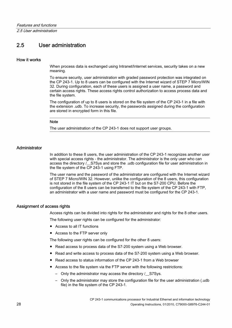
How it works When process data is exchanged using Intranet/Internet services, security takes on a new meaning. To ensure security, user administration with graded password protection was integrated on the CP 243-1. Up to 8 users can be configured with the Internet wizard of STEP 7 Micro/WIN 32. During configuration, each of these users is assigned a user name, a password and certain access rights. These access rights control authorization to access process data and the file system. The configuration of up to 8 users is stored on the file system of the CP 243-1 in a file with the extension .udb. To increase security, the passwords assigned during the configuration are stored in encrypted form in this file.
Note The user administration of the CP 243-1 does not support user groups.
Administrator In addition to these 8 users, the user administration of the CP 243-1 recognizes another user with special access rights - the administrator. The administrator is the only user who can access the directory /__S7Sys and store the .udb configuration file for user administration in the file system of the CP 243-1 using FTP. The user name and the password of the administrator are configured with the Internet wizard of STEP 7 Micro/WIN 32. However, unlike the configuration of the 8 users, this configuration is not stored in the file system of the CP 243-1 IT but on the S7-200 CPU. Before the configuration of the 8 users can be transferred to the file system of the CP 243-1 with FTP, an administrator with a user name and password must be configured for the CP 243-1.
Assignment of access rights Access rights can be divided into rights for the administrator and rights for the 8 other users. The following user rights can be configured for the administrator: ● Access to all IT functions ● Access to the FTP server only The following user rights can be configured for the other 8 users: ● Read access to process data of the S7-200 system using a Web browser. ● Read and write access to process data of the S7-200 system using a Web browser. ● Read access to status information of the CP 243-1 from a Web browser ● Access to the file system via the FTP server with the following restrictions:
– Only the administrator may access the directory /__S7Sys. – Only the administrator may store the configuration file for the user administration (.udb
file) in the file system of the CP 243-1.

Features and functions 2.6 Safety
CP 243-1 communications processor for Industrial Ethernet and information technology Operating Instructions, 01/2010, C79000-G8976-C244-01 29
Note HTML pages can be accessed by a Web browser without password protection. Password protection is not activated until process values of the S7-200 system are accessed by such pages.
Note We recommend that the 8 configurable users do not have access with FTP. If a user is permitted access with FTP, this user can also change the configuration data stored in the file system of the CP 243-1
Note To keep the configuration effort involved in user administration as low as possible, we recommend that you configure abstract users with special rights (for example "commissioning" "maintenance" or "production") instead of natural users (for example "John Anyman").
Character set and number of characters for entering the user name/password Role User name Password Administrator 1 to 16 characters 8 to 16 characters User 1 to 32 characters 1 to 32 characters
Length of the user names and passwords
All ASCII characters between 0x21 and 0x7E can be used for a user name and password.
2.6 Safety
2.6.1 Configuration Part of the configuration of the CP 243-1 is stored retentively on the S7-200 CPU and part in the file system of the CP 243-1. The validity of the part of the configuration stored on the S7-200 CPU is checked using by a CRC mechanism. In contrast, no CRC mechanism is used for the part of the configuration stored in the file system of the CP 243-1. When you save a configuration for the CP 243-1, STEP 7 Micro/WIN 32 calculates a CRC checksum. This checksum is stored together with one part of the configuration. While reading out the part of the configuration stored on the S7-200 CPU, the CP 243-1 checks this checksum so that it can detect undesired changes in the stored configuration data. This CRC mechanism can, however, also be deactivated. The configuration can then be changed manually or by an S7-200 user program.

Features and functions 2.6 Safety
CP 243-1 communications processor for Industrial Ethernet and information technology 30 Operating Instructions, 01/2010, C79000-G8976-C244-01
NOTICE Since, after the CRC check is disabled, the CP 243-1 is no longer able to check the configuration data for consistency in terms of desired or undesired changes, there is no guarantee that the CP or the components connected to the network will function correctly.
NOTICE The CP 243-1 recognizes that the CRC is disabled by a special value of a byte in its configuration. If this value is set in the configuration either accidentally or intentionally, this will disable the CRC check. This is why we strongly recommend that you only create the configuration with the Internet wizard integrated in STEP 7 Micro/WIN 32 and check the S7-200 program for memory operations that affect in the data area in which the configuration data of the CP 243-1 is stored.
2.6.2 Data security The CP 243-1 represents a physical connection between the Internet, Ethernet and the S7-200 bus. It provides: ● No protection against intended or accidental manipulation of the data areas and/or
system states of the local or remote CPUs ● No firewall functionality Internet access by the CP 243-1 to data stored on the S7-200 CPU is possible but always harbors the risk of misuse. For this reason, it is a good idea to change the passwords assigned to the various users at regular intervals. Additional information on the subject of security can be found in the document "Data Security in Industrial Communication". The CP 243-1 terminates an active STEP 7 Micro/WIN 32 connection when no STEP 7 Micro/WIN request was sent to the CPU for a period of 60 seconds. This prevents the Micro/WIN server on the CP 243-1 from being blocked by network errors which would in turn prevent a new connection to STEP 7 Micro/WIN 32.
Note Access by the server to the S7-200 CPU via the CP 243-1 is possible both in CPU RUN and STOP mode. In STOP mode, however, program variables or I/O values are not updated.
NOTICE The user name and related password required to log in on an FTP server are not encrypted when transmitted over the network in compliance with the specifications of the FTP protocol.

Features and functions 2.6 Safety
CP 243-1 communications processor for Industrial Ethernet and information technology Operating Instructions, 01/2010, C79000-G8976-C244-01 31
2.6.3 Reliability of communication The CP 243-1 is equipped with a "keepalive" mechanism. This means that the CP 243-1 can recognize the failure of a communications partner or the relevant connection automatically within a configurable period of time. The keepalive time specified when the CP 243-1 is configured is the time after which this internal mechanism is started and an attempt is made to reach the communications parter. These mechanisms take approximately 10 seconds. If the communications parter cannot be reached during this time, the CP 243-1 automatically terminates the connection to this partner. If the CP 243-1 is the client, it then attempts to establish this connection again. Failure of the communications parter is reported to the user with the mechanisms described in chapter Diagnostics (Page 93). You should always enable the keepalive monitoring on all systems involved in communication if these systems have such a mechanism.
Note The keepalive mechanism will not work unless the communications parter also supports this mechanism in compliance with with RFC 1122 and RFC 793.

Features and functions 2.7 Connectors
CP 243-1 communications processor for Industrial Ethernet and information technology 32 Operating Instructions, 01/2010, C79000-G8976-C244-01
2.7 Connectors
2.7.1 Connectors
Front view:
Figure 2-3 Connectors
The CP 243-1 has the following connectors: ● Terminal block for 24 V DC power and grounding connector ● 8-pin RJ-45 jack for Ethernet connector ● Male connector for S7 bus ● Integrated ribbon cable with connection socket for the S7 bus The connectors are located under the covers of the front doors.

Features and functions 2.8 Codes: Front LEDs
CP 243-1 communications processor for Industrial Ethernet and information technology Operating Instructions, 01/2010, C79000-G8976-C244-01 33
2.8 Codes: Front LEDs
2.8.1 Codes: Front LEDs
Figure 2-4 Front with the LEDs
There are 5 LEDs on the front to indicate the following:
Red, on continuously System fault: Lit when a fault/error has occurred
SF
Red, flashing System fault: Flashes (at an interval of approximately 1 second) if the configuration is incorrect or no BOOTP/DHCP server could be found.
LINK Green, on continuously Connection via the RJ-45 interface: Ethernet connection is established

Features and functions 2.8 Codes: Front LEDs
CP 243-1 communications processor for Industrial Ethernet and information technology 34 Operating Instructions, 01/2010, C79000-G8976-C244-01
RX/TX Green, flickering Ethernet activity:
Data is being received or sent via Ethernet Note: A packet received via Ethernet may not be intended for the CP 243-1. The CP 243-1 first accepts all packets transmitted via Ethernet. and then decides whether the packet is intended for it.
RUN Green, on continuously Ready for operation: The CP 243-1 is ready for communication
CFG Yellow, on continuously Configuration: Lit when STEP 7 Micro/WIN 32 is actively maintaining a connection to the S7-200 CPU via the CP 243-1
Function of the individual LEDs
During the startup phase of the CP 243-1, the SF LED flashes twice. The LINK and the RX/TX LEDs then flash several times. As soon as the RUN LED is lit, the CP 243-1 startup has completed.

CP 243-1 communications processor for Industrial Ethernet and information technology Operating Instructions, 01/2010, C79000-G8976-C244-01 35
Installation and commissioning 33.1 Important notes on installation and commissioning
Safety notices relating to the use of the device The following safety notices must be adhered to when installing, commissioning, connecting, replacing components and opening the device.
General information
WARNING Safety extra-low voltage The equipment is designed for operation with Safety Extra-Low Voltage (SELV) by a Limited Power Source (LPS). This means that only SELV / LPS complying with IEC 60950-1 / EN 60950-1 / VDE 0805-1 must be connected to the power supply terminals. The power supply unit for the equipment power supply must comply with NEC Class 2, as described by the National Electrical Code (r) (ANSI / NFPA 70). There is an additional requirement if devices are operated with a redundant power supply: If the equipment is connected to a redundant power supply (two separate power supplies), both must meet these requirements.
General notices for use in hazardous areas
WARNING Risk of explosion when connecting or disconnecting the device EXPLOSION HAZARD DO NOT CONNECT OR DISCONNECT EQUIPMENT WHEN A FLAMMABLE OR COMBUSTIBLE ATMOSPHERE IS PRESENT.
WARNING Replacing components EXPLOSION HAZARD SUBSTITUTION OF COMPONENTS MAY IMPAIR SUITABILITY FOR CLASS I, DIVISION 2 OR ZONE 2.

Installation and commissioning 3.2 Installation and commissioning
CP 243-1 communications processor for Industrial Ethernet and information technology 36 Operating Instructions, 01/2010, C79000-G8976-C244-01
WARNING Opening the device EXPLOSION HAZARD DO NOT OPEN WHEN ENERGIZED.
General notices for use in hazardous areas according to ATEX
WARNING Requirements for the cabinet/enclosure When used in hazardous environments corresponding to Class I, Division 2 or Class I, Zone 2, the device must be installed in a cabinet or a suitable enclosure. To comply with EU Directive 94/9 (ATEX95), this enclosure must meet the requirements of at least IP54 in compliance with EN 60529.
WARNING Suitable cables for temperatures in excess of 70 °C If the cable or conduit entry point exceeds 70 °C or the branching point of conductors exceeds 80 °C, special precautions must be taken. If the equipment is operated in an air ambient in excess of 50 °C, only use cables with admitted maximum operating temperature of at least 80 °C.
WARNING Protection against transient voltage surges Take measures to prevent transient voltage surges of more than 40% of the rated voltage. This is the case if you only operate devices with SELV (safety extra-low voltage).
3.2 Installation and commissioning
Installation You can install the devices of the S7-200 series either in a switching panel or on a DIN rail. You can arrange the modules both horizontally and vertically. The S7-200 CPU and the expansion modules are designed for natural heat dissipation by convection. For this reason, leave at least 25 mm of free space above and below the devices so that the heat is free to escape. Long operating times at maximum ambient temperatures and maximum loads will shorten the lifespan of the electrical components of the device.

Installation and commissioning 3.2 Installation and commissioning
CP 243-1 communications processor for Industrial Ethernet and information technology Operating Instructions, 01/2010, C79000-G8976-C244-01 37
Note The position in an S7-200 system at which a CP 243-1 can be operated depends on the firmware version of the S7-200 CPU you are using. When using firmware version 1.2 or higher, the CP 243-1 can be installed in any one of 7 positions in an S7-200 system. With firmware versions lower than version 1.2, the CP 243-1 must be installed in position 0 unless another intelligent module is installed in position 0, in which case the CP 243-1 may be installed in position 1.
Wiring
WARNING If you attempt to install or remove the CP 243-1 or other devices while they are on, you may receive an electric shock or the devices may not work properly. If the power for the CP 243-1 and all connected devices is not switched off while the devices are being installed/removed, this may cause injury and/or property damage. Take all necessary safety precautions and make sure that the power for the S7-200 and the CP 243-1 is turned off before you begin wiring.
General guidelines Below, you will find some general guidelines for wiring your programmable controller: ● Make sure that you comply with all valid and binding standards when you wire your CP
243-1. When installing and operating the device, keep to the relevant national and regional regulations. Ask your local authorities for the standards and regulations that apply to your specific situation.
● Only wire up the S7-200 CPU and the CP 243-1 when the power is turned off! ● Use cables with a cross section suitable for power you are using. The 24 V power supply
of the CP 243-1 can be wired with wires with a cross section between 0.50 mm² and 1.50 mm². When wiring of the grounding terminal, use wires with a cross section of 1.50 mm².
● Do not screw down the connection terminals too tightly. The maximum tightening torque is 0.56 Nm.
● Keep the wires as short as possible. You should wire in pairs: one neutral or zero conductor together with a phase conductor or a signal line.
● Separate alternating current wiring and high voltage direct current wiring with fast switching sequences from the low voltage signal wiring.
● Provide suitable surge protection for cables that may be hit by lightning. ● The S7-200 CPU and the CP 243-1 should be connected to the same power supply! ● The CP 243-1 is equipped with an integrated ribbon cable with a socket for fast
connection to other S7-200 components.

Installation and commissioning 3.2 Installation and commissioning
CP 243-1 communications processor for Industrial Ethernet and information technology 38 Operating Instructions, 01/2010, C79000-G8976-C244-01
● The slot in which a CP 243-1 can be operated depends on the firmware version of the S7-200 CPU being used (see note in section 3.2).
● A maximum of one CP 243-1 per CPU is supported.
Electrical requirements The input voltage must always be +24 V DC. Apply 24 V direct current only from power sources that provide safe electrical isolation from 120/230 V AC and similar sources of danger. Safe electrical isolation is, for example, defined in the following standards: ● PELV complying with EN 60204-1 ● Class 2 or circuit with limited voltage/current according to UL 508 The power supply on the S7-200 bus is provided by the S7-200 CPU. Make sure that the CP 243-1 is correctly grounded.
Space requirements for installation When installing your module, keep to the following guidelines: ● The CP 243-1 is designed for natural heat dissipation by convection. For this reason,
leave at least 25 mm free space above and below the device to allow heat to escape. Long operating times at maximum ambient temperatures and maximum loads will shorten the lifespan of the electrical components of the device.
● When installed vertically, the maximum permissible ambient temperature drops by 10 °C. The CP 243-1 must be positioned above the CPU. If you are using a vertical standard DIN rail, you should use standard DIN rail stoppers to prevent the module from slipping.
● Installation depth is 75 mm.
Note Set up your devices so that there is still enough space to wire the inputs and outputs and to connect the communication cables.
75 m m
CP 243-1Frontcovering
Installationsurface
S ide view
CP 243-1
25 m m
25 m m
Front view
S7-200Distance for correctheat dissipation
Figure 3-1 Space requirements for installation

Installation and commissioning 3.3 Dimensions for installation in a switching panel
CP 243-1 communications processor for Industrial Ethernet and information technology Operating Instructions, 01/2010, C79000-G8976-C244-01 39
3.3 Dimensions for installation in a switching panel The CP 243-1 has holes that make it easier to install in a switching panel.
CP 243-1
63.2 mm
71.2 mm
96 mm
88 mm
80 mm
Minimum distance of 9.5 mmbetween the modules wheninstalled in control cabinets
via screws M4
CPU
Figure 3-2 Dimensions for installation in a switching panel
3.4 Dimensions for installation on a DIN rail The CP 243-1 can be mounted on a DIN rail (DIN EN 50 022). The following figure shows the dimensions of a standard DIN rail:
35 m m
7.5 m m
1.0 m m
Figure 3-3 Dimensions for installation on a DIN rail

Installation and commissioning 3.5 Installation in a panel
CP 243-1 communications processor for Industrial Ethernet and information technology 40 Operating Instructions, 01/2010, C79000-G8976-C244-01
3.5 Installation in a panel
3.5.1 Installation in a panel
What to do / steps 1. Bore holes for DIN M4 screws on the panel. Read and follow the instructions and use the
dimensions in sections 3 and 3.1 for installation in a panel. 2. Screw the CP 243-1 to the panel to the right of the CPU for horizontal installation and
above the CPU for vertical installation. Use DIN M4 screws. 3. Insert the ribbon cable of the CP 243-1 in the connector under the front cover of the
adjacent module or the S7-200 CPU. The shape of the plug prevents it from being incorrectly inserted.
4. Connect the grounding terminal: Connect the grounding terminal of the CP 243-1 with the nearest available ground to obtain the highest possible interference immunity. We recommend that you connect all grounding terminals individually. Use wires with a cross section of 1.5 mm2.
5. Connect the power supply. 6. Connect the Ethernet cable. The transmission medium is a 2 x 2-wire, twisted pair, shielded cable with a characteristic impedance of 100 ohms. The transmission properties of this cable must meet category 5 requirements (Cat5 cable). The maximum length of the connection between an end device and network component (link segment) is limited to 100 m with the components defined in IEEE802.3. The RJ-45 plug on the CP 243-1 is shielded so that, in combination with a shielded Ethernet cable, a continuous cable shield is created that ensures interference-free Ethernet transmission. The shield of the RJ-45 plug is connected via the grounding terminal of the CP 243-1. We recommend that you shield and ground the Ethernet connection as described in the document "SIMATIC NET Twisted Pair and Fiber-Optic Networks". Installation is now complete.
Note Keep the front cover of the CP 243-1 closed during operation. During installation, make sure that the upper and lower ventilation slits of the module are not obstructed and good ventilation is possible.

Installation and commissioning 3.6 Installation on a standard DIN rail
CP 243-1 communications processor for Industrial Ethernet and information technology Operating Instructions, 01/2010, C79000-G8976-C244-01 41
3.6 Installation on a standard DIN rail
Installation on a standard DIN rail 1. Open the catch and hang the CP 243-1 on the DIN rail to the right of or above the CPU. 2. Close the catch to secure the CP 243-1 to the rail. Make sure that the catch snaps in
correctly and that the device is firmly secured to the rail.
Note In environments in which strong vibration occurs or when the devices are installed vertically, it may be necessary to use standard DIN rail stoppers to keep the devices from slipping down the DIN rail.
3. Insert the ribbon cable of the CP 243-1 in the connector under the front cover of the adjacent module or the S7-200 CPU. The shape of the plug prevents it from being incorrectly inserted.
4. Connect the grounding terminal: 5. Connect the grounding terminal of the CP 243-1 with the nearest available ground to
obtain the highest possible interference immunity. We recommend that you connect all grounding terminals individually. Use wires with a cross section of 1.5 mm2.
6. Connect the power supply. 7. Connect the Ethernet cable.
The transmission medium is a 2 x 2-wire, twisted pair, shielded cable with a characteristic impedance of 100 ohms. The transmission properties of this cable must meet category 5 requirements (Cat5 cable). The maximum length of the connection between an end device and network component (link segment) is limited to 100 m with the components defined in IEEE802.3. The RJ-45 plug on the CP 243-1 is shielded so that, in combination with a shielded Ethernet cable, a continuous cable shield is created that ensures interference-free Ethernet transmission. The shield of the RJ-45 plug is connected via the grounding terminal of the CP 243-1. We recommend that you shield and ground the Ethernet connection as described in the document "SIMATIC NET Twisted Pair and Fiber-Optic Networks".
Installation is now complete.
Note Keep the front cover of the CP 243-1 closed during operation. During installation, make sure that the upper and lower ventilation slits of the module are not obstructed and good ventilation is possible.

Installation and commissioning 3.7 Replacing a module
CP 243-1 communications processor for Industrial Ethernet and information technology 42 Operating Instructions, 01/2010, C79000-G8976-C244-01
3.7 Replacing a module
3.7.1 Replacing a module When the CP 243-1 (6GK7243-1EX01-0XE0) module is replaced, no new programming is required on the S7 communication side since the configuration data and the user program are stored retentively on the S7-200 CPU. The CP 243-1 must be programmed again for the IT functions since the configuration files for the IT services are stored in the file system of the CP 243-1.
3.8 Uninstalling the CP 243-1
WARNING If you attempt to install or remove the CP 243-1 or other devices while they are on, you may receive an electric shock or the devices may not work properly. If the power for the CP 243-1 and all connected devices is not switched off while the devices are being installed/removed, this may cause injury and/or property damage. Take all necessary safety precautions and make sure that the power is turned off before you install or remove a device.
Follow the steps below to remove the CP 243-1 or any other expansion module of the S7-200: 1. Turn off the power supply of the S7-200 CPU, the CP 243-1 and all expansion modules. 2. Disconnect all cables and wires from the device you want to remove. 3. Open the front cover and disconnect the ribbon cable from the adjacent modules. 4. Remove the screws or open the catch and remove the module from the panel or the DIN
rail.
WARNING
If you install the wrong device, the S7-200 may become unpredictable. If the CP 243-1 is not aligned correctly, this may cause injury and/or property damage. Make sure that you always align the CP 243-1 correctly.

CP 243-1 communications processor for Industrial Ethernet and information technology Operating Instructions, 01/2010, C79000-G8976-C244-01 43
Configuration 44.1 Configuration options
Using the CP 243-1, an S7-200 system can communicate via the S7 protocol with another S7-200 system or an S7-300 / S7-400 or an OPC-based system. Using the IT protocols SMTP, FTP and HTTP, communication is also possible with any computer system that supports these protocols. There are two ways to configure one of these communication modes for an S7-200 system: ● Configuration using STEP 7 Micro/WIN 32, version 3.2.3 or higher ● Configuration by an S7-200 user program The configuration data for the IT services is located in the file system of the CP 243-1. This is read during startup and then monitored continuously for changes. This means that every change to this data during ongoing operation is immediately adopted by CP 243-1. All other configuration data is stored in the data block of the S7-200 CPU. From there, this data is read once each time the CP 243-1 restarts.
NOTICE A change to the configuration stored on the S7-200 CPU by an S7-200 user program is only possible when the CRC mechanism is disabled. After the CRC check is disabled, the CP 243-1 is no longer able to check the configuration data for consistency in terms of desired or undesired changes, so there is no guarantee that the CP or the components connected to the network will function correctly.
NOTICE To ensure that the configuration data of the CP 243-1 stored on the S7-200 CPU will also be retained if a power failure occurs, this data must be stored in a retentive memory area on the S7-200 CPU. As default in an S7-200 system, the entire data block is defined as retentive. However, a reconfiguration could change this default setting on your S7-200 system.
Changes to the configuration data stored on the S7-200 CPU do not take effect until the next CP 243-1 restart. When STEP 7 Micro/WIN 32 is used for new/modified configuration of the CP 243-1, this automatically triggers a restart of the CP 243-1 as soon as the mode changes from STOP to RUN. If, on the other hand, the CP 243-1 is configured directly by the S7-200 user program, this configuration can be activated by the user program by calling the subroutine "ETHx_CFG". Calling this subroutine also triggers a restart on the CP 243-1. The TCP/IP address parameters (IP address, subnet mask, IP address of a gateway) can be specified during configuration in one of two ways. They can be specified permanently or dynamically (the CP 243-1 obtains the TCP/IP address parameters from a BOOTP/DHCP server during startup). The configuration data stored in the memory of the S7-200 CPU can be downloaded to the S7-200 CPU via the PPI interface. If the CP 243-1 already has an IP address, this

Configuration 4.2 Value ranges of the configuration data
CP 243-1 communications processor for Industrial Ethernet and information technology 44 Operating Instructions, 01/2010, C79000-G8976-C244-01
configuration data can also be downloaded to the S7-200 CPU using TCP/IP and the Ethernet interface of the CP 243-1. The CP 243-1 must already have an IP address before the configuration data of the IT services can be downloaded to the CP 243-1. If you want an S7-200 system to communicate via a CP 243-1 with an S7-300, an S7-400 or an OPC-based system, use STEP 7 with at least version 5.1 and service pack 3 or higher (with NCM S7 for Industrial Ethernet) for configuration.
Note After startup, the CP 243-1 may automatically change the configured gateway due to special network-based services ("ICMPRedirect"). After approximately 30 seconds, however, the CP 243-1 returns to the originally configured gateway. This means that the gateway actually used by the CP 243-1 may sometimes differ from the one in the configuration. You can change the gateway currently used by the CP 243-1 either using the diagnostics window for the CP 243-1 in STEP 7 Micro/WIN 32 or a user program that reads from the memory area of the S7-200 CPU in which the NPB data block is stored (see chapter Structure of the network parameter block (NPB) (Page 61)).
4.2 Value ranges of the configuration data
4.2.1 IP addresses The IP addresses that need to be specified at various points in the configuration must comply with the general conventions governing the validity of IP addresses. According to this convention, the following IP addresses have a special significance: Loopback 127.0.0.0 - 127.255.255.255 Class D addresses 224.0.0.0 - 239.255.255.255 Class E addresses 240.0.0.0 - 247.255.255.255 Broadcast addresses for example 255.255.255.255
The CP 243-1 does not accept these addresses. The only exception is the loopback address 127.0.0.1 that can be used during configuration of the FTP client service. This causes data to be transferred between the memory of the local S7-200 CPU and the file system of the local CP 243-1 when the relevant function is called.
4.2.2 Subnet mask If a subnet mask is specified in the configuration, its structure must comply with the general conventions governing the validity of subnet masks. Remember that the validity of an IP address and a related subnet mask are dependent on each other.

Configuration 4.2 Value ranges of the configuration data
CP 243-1 communications processor for Industrial Ethernet and information technology Operating Instructions, 01/2010, C79000-G8976-C244-01 45
4.2.3 TSAPs TSAPs consist of 2 bytes. The first byte specifies the connection. The second byte is created from the rack number and the slot of the communications module. The following value ranges apply to the first byte. Range of values for the local TSAP 16#02, 16#10 - 16#FE Range of values for the remote TSAP 16#02, 16#03, 16#10 - 16#FE
The CP 243-1 does not check the value of the second byte.
4.2.4 Ports Each standard protocol from the TCP/IP protocol family (for example HTTP, FTP or SMTP) is assigned to a separate fixed port number with which a related communication service can usually be accessed in a TCP/IP network. These permanently assigned port numbers are called "well-known" port numbers since they were specified worldwide in the definition of the protocol. Standard protocols usually use port numbers between 0 and 1024. Port numbers higher than 1024 are not fixed and can be assigned by the user programs as required. Thanks to modern protection mechanisms in TCP/IP networks (for example firewalls), the ports usually used by standard protocols are rerouted to other ports. To allow the CP 243-1 to be able to communicate with external SMTP servers even in such environments, you can explicitly specify the port via which such a server can be accessed when you configure the e-mail service with the Internet wizard of STEP 7 Micro/WIN 32. Standard SMTP servers can be accessed with port 25.
4.2.5 E-mail tags An e-mail consists of one or two address fields, a field for the subject and a field for the text message. The text message is made up of ASCII characters. In addition to the two control characters \n and \t, the text can also contain placeholders defining an embedded data value. When an e-mail is sent, the CP 243-1 reads the current value of such a placeholder from the local S7-200 CPU, formats it and inserts it in the message. Such placeholders use the following syntax: %address:places_before_decimal_point.places_after_decimal_pointFormat% The percent character (%) indicates the beginning and the end of a placeholder. The colon (:) separates the address from the formatting instructions. The period (.) separates the places before the decimal point and the places after the decimal point within the formatting instructions.
Note Use the notation %% to represent individual % characters in a text message. Example: Required text: "The fill level is specified in %" Text you enter: "The fill level is specified in %%"

Configuration 4.2 Value ranges of the configuration data
CP 243-1 communications processor for Industrial Ethernet and information technology 46 Operating Instructions, 01/2010, C79000-G8976-C244-01
The address element specifies the address, the data type and the size of the embedded data value (for example VD100, VW50 or MB20). The permitted data types are input, output, bit memory, special memory bits, variables and analog input. The CP 243-1 supports both the German designations of these data types (E, A, M, SM, V and AE) and the international notations (I, Q, M, SM, V and AI). Each of these data types can be addressed as byte, word and double word. The size of the address depends on the type of data or the type of S7-200 CPU used. (A CPU 226XM provides a variable memory area of 10240 bytes.) The element "places_before_decimal_point" defines the minimum number of digits that are shown to the left of the decimal point. This value should be high enough to hold the expected data value range and, where necessary, a sign. If there are not enough places specified in the element "places_before_decimal_point" to completely represent a current value, this value is still shown completely. The specified format is ignored in this case. If the representation of a current value requires fewer places than specified in the element "places_before_decimal_point," the remaining places are padded with blanks. The valid range for the element "places_before_decimal_point" is between 1 and 10. The element "places_after_decimal_point" defines the number of digits shown to the right of the decimal point. If a data value to the right of the decimal point contains zeros, these are represented as defined by the element "places_after_decimal_point". If the element "places_after_decimal_point" is zero, the value is shown without decimal point. The valid range for the element "places_after_decimal_point" is between 0 and 10. The format element specifies the format for representing the embedded value. The following characters are permitted in the format element: I,i: Integer with sign U,u: Unsigned integer H,h: Hexadecimal F,f: Floating point/real
Example: Below, you will find several examples of how different formatting instructions affect the representation of a current value:
Current value Formatting instruction Output
(⃞ corresponds to a blank) 16#F4 in address VB0 %VB0:1.0I% -12 16#F4 in address VB0 %VB0:6.0I% ⃞⃞⃞-12 16#F4 in address VB0 %VB0:6.3I% ⃞⃞⃞⃞-0.012 16#0C in address VB0 %VB0:2.0H% 16#0C 16#0C in address VB0 (16#00 for the next byte)
%VW0:4.0H% 16#000C
16#0C in address VB0 (16#00 for the next 3 bytes)
%VD0:8.0H% 16#0000000C
Examples of formatting for placeholder information in e-mails

Configuration 4.3 Configuring a CP 243-1 with STEP 7
CP 243-1 communications processor for Industrial Ethernet and information technology Operating Instructions, 01/2010, C79000-G8976-C244-01 47
Note Integers with sign (format element I) and unsigned integers without sign (format element U) can be interpreted as fixed point decimal numbers. Example: VD100 contains the fixed point number for the value to be interpreted 12345dec. If the placeholder %VD100:2.3U% is used for this value in an e-mail, this value is transferred in the e-mail as 12.345. Calculation: Result = value / (10^number of desired places after the decimal point) --> 12.345 =12345/10^3
Note Received e-mails may also contain #### in the placeholder instead of the expected value. This always happens when a placeholder could not be filled with a value that conformed to the formatting instructions.
4.3 Configuring a CP 243-1 with STEP 7 Once you have installed and started STEP 7 Micro/WIN 32 on your PC, start the wizard for the CP 243-1. You will find this in the "Options" menu under "Internet Wizard..." or in the left window area of STEP 7 Micro/WIN 32 in the window with the navigation bar under "Options" if the correct view is enabled in STEP 7 Micro/WIN 32. The Internet wizard supports you when configuring your CP 243-1. You can enter all the relevant configuration data in a series of dialogs. User prompting is designed so that you cannot move on to the next dialog until all your entries are correct and complete. If they are not, an error message appears to this effect. The Internet wizard consists of four internal wizards that are used to configure the various IT services. You always work through the configuration wizard first. In this wizard, basic configuration data is specified (such as TCP/IP address parameters) and you also configure S7 communication here. All configuration information specified here is stored on the S7-200 CPU when downloaded to your S7-200 system. After you have completed this wizard, you can exit the configuration or configure the various IT services of the CP 243-1 with further wizards. If you want to do this, the Internet wizard includes an FTP wizard and an e-mail wizard as well as a wizard for configuring user administration. The information specified in these wizards is stored in the file system of the CP 243-1 when downloaded to the S7-200 system. The configuration of each CP 243-1 can be completed after working through one of these three wizards. If one of these wizards is not worked through before you complete the configuration, this IT service is not configured. Below is a short description of the individual wizards and the individual steps in configuration through which these wizards will guide you.

Configuration 4.3 Configuring a CP 243-1 with STEP 7
CP 243-1 communications processor for Industrial Ethernet and information technology 48 Operating Instructions, 01/2010, C79000-G8976-C244-01
Note For detailed information, refer to the STEP 7 Micro/WIN 32 documentation included with STEP 7 Micro/WIN 32.
4.3.1 Basic configurations After starting the Internet wizard, you will see the configuration wizard. All the settings you enter here will be stored on the S7-200 CPU when you download to the S7-200 system. The introductory dialog of the configuration wizard provides you with general information. After reading this, click "Next>" to continue with the wizard.
Specifying of the position of the CP 243-1 in the S7-200 system The position of the CP 243-1 in the S7-200 system must be specified in the second dialog. This position can be set manually or the wizard can search for a CP 243-1 in your S7-200 system. If it finds a CP 243-1, its position in the S7-200 system is displayed. If you double-click on the displayed CP 243-1, you accept its position in the configuration.
Specifying TCP/IP address parameters and transmission type In the next dialog, you specify the TCP/IP address parameters and the type of transmission to be used. There are two ways of entering the TCP/IP address parameters: 1. Enter these parameters manually in the relevant input boxes. 2. Enable access to a BOOTP/DHCP server. In this case, the CP 243-1 obtains its TCP/IP
address parameters from a BOOTP/DHCP server during startup. If the CP 243-1 is unable to find a BOOTP/DHCP server in your TCP/IP network, it performs a reset, restarts and tries again to establish contact with a BOOTP/DHCP server. It repeats this until it finds a BOOTP/DHCP server from which it can obtain TCP/IP address parameters.
Specifying the module command byte and the number of S7 point-to-point links In the next dialog, you enter the address of the bytes in the address area of your S7-200 system via which the CP 243-1 can be accessed by the S7-200 CPU. This address depends on the position of the CP 243-1 in your S7-200 system and the number of outputs in your S7-200 system. If you used the wizard to search for the position of the CP 243-1 in your S7-200 system at the beginning of the configuration, the wizard will set the address to be used here. You can always use STEP 7 Micro/WIN 32 to identify the address areas occupied by the modules in your S7-200 system by enabling the entry "Information…" in the "PLC" menu. This also finds the address with which your CP 243-1 can be accessed in your S7-200 system. In this dialog, you also specify how many S7 connections need to be set up on your CP 243-1. Up to 8 such connections are possible. A dialog appears for each connection that you specify here. You can then configure the connection in this dialog.

Configuration 4.3 Configuring a CP 243-1 with STEP 7
CP 243-1 communications processor for Industrial Ethernet and information technology Operating Instructions, 01/2010, C79000-G8976-C244-01 49
Configuring the individual S7 connections The following dialogs are used to configure the S7 connections that you set up in the previous dialog. First, specify for each of these connections whether your S7-200 system will be client or server. The layout of the dialog changes according to the option you choose. If you want your S7-200 system to be a client on a connection, enter the address of the communications partner and the Transport Service Access Point (TSAP) for this partner. In an additional dialog, you also need to specify the data to be exchanged between your S7-200 system and the specified communications partner. Here, you also specify whether this data will be read or written. Up to 32 read/write requests can be specified per connection. If you want your S7-200 system to be a server on a connection, you can assign an IP address to specify which communications partner will have access to your system. You can also set each server so that it allows access from every IP address. You must also specify the transport service access point (TSAP) in the communications partner you are allowing to access your S7-200 system. Keepalive monitoring can be enabled for both client and server connections. For the transport communication access points (TSAPs) of your communications partner, refer to the configuration of the specific partner. With an S7-200 system, this is created with STEP 7 Micro/WIN 32. With an S7-300, S7-400 or OPC-based system, use STEP 7 (see also chapter Other options when configuring a CP 243-1 (Page 54)).
Note The specified communication access points (TSAPs) in STEP 7 and in STEP 7 Micro/WIN 32 must be compatible.
Enabling/disabling the CRC mechanism and specifying the monitoring time After you have finished configuring the S7 connection, another dialog opens in which you decide whether your configuration data on the S7-200 CPU will be protected against accidental overwriting by using CRC. If CRC is activated, during startup the CP 243-1 checks whether the configuration that it reads from the memory of the S7-200 CPU was overwritten by the user program. If it was, it interrupts the startup and attempts to obtain its TCP/IP address parameters from a BOOTP/DHCP server. If it succeeds, startup is continued. However, only the Micro/WIN channel is enabled afterwards. The CP 243-1 can then only communicate with STEP 7 Micro/WIN 32 but not with other partners. We recommend that you always activate CRC. This is the only way in which the CP 243-1 can detect that the user program has made undesired changes to the configuration data. If CRC is not enabled, your user program can change the configuration data of the CP 243-1. However, the CP 243-1 does not recognize that data has been accidentally overwritten.

Configuration 4.3 Configuring a CP 243-1 with STEP 7
CP 243-1 communications processor for Industrial Ethernet and information technology 50 Operating Instructions, 01/2010, C79000-G8976-C244-01
NOTICE An S7-200 user program can only change the configuration data on the S7-200 CPU when CRC is disabled. After CRC is disabled, the CP 243-1 can no longer check the configuration data for consistency in terms of desired or undesired changes, and there is therefore no guarantee that the CP or the components connected to the network will function correctly.
In the same dialog you also can set a common keepalive time for all configured connections. The value entered here is the time after which the CP 243-1 recognizes the problem described in chapter Reliability of communication (Page 31). You specified which connections are to be monitored with this time when you configured the individual connections.
Setting up an administrator The next dialog (administrator account) is used to specify the user identifier and the password for the administrator. You also specify whether the administrator will have the right to access the process data of the S7-200 system with a Web browser.
Enabling the individual IT services The next dialog can be used to enable various IT services of the CP 243-1 individually. Every IT service that will be used later with the CP 243-1 must be selected as enabled in this dialog. Any service not selected in this dialog will not be started when the CP 243-1 starts up and will remain unavailable. The exception to this is the FTP server on the CP 243-1 which is always enabled. When configuring the CP 243-1, only enable the IT services that will actually be used in your application. At this point in the configuration, whether or not you enable an IT service has no effect on the configuration steps below.
Specifying the area for storing the configuration In the next dialog, specify the memory area in which your configuration data will be stored on the S7-200 CPU. The wizard supports you throughout.
Information on the created subroutines In the next dialog, the wizard shows you which subroutines it has set up based on your configuration and where their configuration data is stored.
NOTICE Make sure that the memory area in which the configuration data of the Internet wizard is stored is not used by your S7-200 user program.

Configuration 4.3 Configuring a CP 243-1 with STEP 7
CP 243-1 communications processor for Industrial Ethernet and information technology Operating Instructions, 01/2010, C79000-G8976-C244-01 51
Completion of the first configuration phase You have now worked through the configuration wizard and completed the first phase of configuration. In the next dialog, you can call the wizards for the IT services. Click the required icon in the left-hand pane of the dialog. If you do not want to use any of the IT services on your CP 243-1, you can complete configuration at this point. Simply click "Finish".
4.3.2 Configuration of user administration To change to the wizard for configuring user administration, click the relevant icon in the left-hand pane of the dialog. All the information entered in this wizard is stored in the file system of the CP 243-1 in a file with the extension .udb when you download to the S7-200 system.
Configuring the users Using the dialogs that open now, you can configure up to 8 users. You assign a user identifier, a password and user-specific access rights to each user. Make sure that the user identifiers are unique. As soon as you have configured the necessary number of users, you can click "Next" to complete user configuration. Then either change to another wizard or complete the configuration of the CP 243-1 by clicking "Finish".
4.3.3 Configuration of the e-mail functions To change to the wizard to configure the e-mail functions, click the icon in the left-hand pane of the dialog. All the information entered in this wizard is stored in the file system of the CP 243-1 in a file with the extension .edb when the configuration is downloaded to the S7-200 system.
Configuring the e-mail address and the e-mail server to be used In the first dialog of the e-mail wizard, assign an e-mail address to your S7-200 system. The e-mail address specified here will be entered as the sender address in all e-mails sent. Then select an e-mail server to which your CP 243-1 will send the e-mails. Enter the IP address and the port of this e-mail server. An e-mail server can usually be accessed via port 25. This port is the default. If the e-mail server you specified uses a different port, enter this port in the relevant box. To increase reliability, you can enter a second e-mail server. The CP 243-1 attempts to send an e-mail to the e-mail server specified first. If this server cannot be reached (for example due to a network malfunction), the CP 243-1 then attempts to send the e-mail to the second e-mail server. If the second e-mail server is also unreachable, the CP 243-1 aborts its attempts to send the e-mail and outputs an error message to this effect.

Configuration 4.3 Configuring a CP 243-1 with STEP 7
CP 243-1 communications processor for Industrial Ethernet and information technology 52 Operating Instructions, 01/2010, C79000-G8976-C244-01
Configuring the e-mails The next dialog is used to configure the e-mails. In this dialog, enter the address to which the e-mail will be sent for every e-mail to be sent by the CP 243-1. You can also enter a second recipient to receive a a copy of the e-mail. Here, you also enter the subject. Placeholders for data from the S7-200 system can be inserted in the actual e-mail text to be sent. When the e-mail is sent, the CP 243-1 replaces each of these placeholders with the current value of the data. To insert such a placeholder in your e-mail, click "Insert Data". In the dialog that then opens, create the placeholder you want to insert. Specify the address of the data to be transferred and the format in which this data will be shown in the e-mail. A total of up to 32 different e-mails can be configured. As soon as you have configured the required number of e-mails, click "Next" to exit the e-mail wizard. Then either change to another wizard or complete the configuration of the CP 243-1 by clicking "Finish".
Authentication CPs that use ESMTP with authentication support the following authentication methods: ● PLAIN ● LOGIN ● CRAM−MD5 ● DIGEST−MD5 In terms of authentication for communication between the CP and mail server, the following situations are possible: ● CP and mail server use authentication (same method)
Once the CP has established a connection to the mail server, the mail server sends a list of the authentication methods it supports. The CP searches through the received list for the supported authentication method. The authentication methods are searched for in the order shown above. The first method found in the list is then used. The CP informs the mail server of this. The data required for authentication (user name and password) is generated by the Micro/WIN wizard and stored in the file system of the CP when the configuration is downloaded. The user name and password correspond to the login data at the mail service provider. If you do not specify a user name and password in the DB, there will be no authentication.
● CP and mail server use authentication (different methods) If the CP does not find a matching authentication method, it aborts the attempt to send and generates a diagnostics message.
● The CP uses authentication, the mail server does not If you use a CP that supports authentication and you want to work without authentication, do not store a user name or password in the e-mail data block. In this situation, the CP transfers data using SMTP.

Configuration 4.3 Configuring a CP 243-1 with STEP 7
CP 243-1 communications processor for Industrial Ethernet and information technology Operating Instructions, 01/2010, C79000-G8976-C244-01 53
● The mail server uses authentication, the CP does not The mail server aborts the attempt to send.
Note If you use authenticated e-mail, you can only specify one e-mail server.
To be able to use authentication for the e-mail server, select the check box in the dialog after you have entered the e-mail address. The lower part of the dialog changes. Now enter the address or the symbolic name of the SMTP server. If you address the SMTP server by name, you will also need to specify the IP address of the DNS server. Although the number of the port can be changed, it is normally 25. To complete your entries in the dialog, enter a user name and password.
4.3.4 Configuring the FTP functions To change to the wizard for configuring the FTP functions, click its icon in the left-hand pane of the dialog. All the information entered in the FTP wizard is stored in the file system of the CP 243-1 in a file with the extension .fdb when you download to the S7-200 system. Using the FTP wizard, you can configure the FTP requests to be sent by your S7-200 user program via the FTP client on the CP 243-1. The FTP server does not need to be configured. This server is automatically started by the CP 243-1 during startup. Access rights to this FTP server are specified in the configuration of the user administration.
Configuring the FTP requests To configure an FTP request, you must first specify whether this is a read, write or delete request and the FTP server to which the request will be sent. With write requests, enter which data you want to send to the specified FTP server from the memory of your S7-200 CPU. You do this by specifying the start address and the length of the data to be transferred. With read requests, specify where the received data will be stored in the memory of your S7-200 CPU. Also specify how many bytes will be transmitted. If you enter a zero as the length, the entire contents of the specified file are copied to the memory of your S7-200 CPU, starting at the specified start address.
NOTICE The CP 243-1 and the FTP wizard can only perform very limited plausibility checks on the address and length information entered when the FTP requests are configured. In particular with read requests, only a rudimentary check can be made as to whether system or user data is overwritten in the memory of the S7-200 CPU based on the specified address and length information. This is the responsibility of the user alone.
For each FTP request, you must specify the FTP server to which the request will be sent and the name of the file to which the request applies. You do this by entering the IP address of the FTP server and the name of the file including any required path information. Execution of

Configuration 4.4 Other options when configuring a CP 243-1
CP 243-1 communications processor for Industrial Ethernet and information technology 54 Operating Instructions, 01/2010, C79000-G8976-C244-01
an FTP request also requires that you specify a valid user identifier for the FTP server including the related password. Up to 32 FTP requests can be configured. As soon as you have configured the required number of FTP requests, click "Next" to exit the FTP wizard. Then either change to another wizard or complete the configuration of the CP 243-1 by clicking "Finish".
4.3.5 Completing configuration During completion of the configuration of the CP 243-1, the Internet wizard sets up all required subroutines so that an S7-200 user program can access the CP 243-1 as specified in the configuration. This means that the subroutine required to enable a certain service is only set up if this service was actually configured.
4.4 Other options when configuring a CP 243-1 Some of the configuration data of the CP 243-1 is stored in the memory of the S7-200 CPU while some is stored in the file system of the CP 243-1. The memory of the S7-200 CPU contains the Ethernet configuration and the basic settings (for example enabling or disabling individual IT services) made for an IT configuration. While it is starting up, the CP 243-1 reads this part of the configuration from the memory of the S7-200 CPU and evaluates it (during ongoing operation, it monitors it continuously for changes). The IT-specific configurations consisting of the configuration of the e-mail client, the FTP client and the user administration are stored in the file system of the CP 243-1 IT in the directory /flash:/config in files with the extensions .edb, .fdb and .udb. Each one of these configuration files has a TIMESTAMP element containing a time stamp that is read cyclically by the CP 243-1. If the CP 243-1 detects that a TIMESTAMP element has changed since it was read the last time, the file involved is read completely and the CP 243-1 reconfigures itself dynamically with the configuration in this file. This means that a change in one of the three configuration files only affects the CP 243-1 if the TIMESTAMP element was also changed.
Access to the configuration data in the memory of the CPU The configuration data stored in the memory of the S7-200 CPU can also be changed directly by an S7-200 user program. For the CP 243-1 to accept configuration data changed in this way when it restarts, the CRC protective mechanism for configuration data must be disabled. The value 16#AC must be entered in byte 13 of the CDB data structure. This happens automatically as soon as the CRC mechanism is disabled in the Internet wizard.

Configuration 4.4 Other options when configuring a CP 243-1
CP 243-1 communications processor for Industrial Ethernet and information technology Operating Instructions, 01/2010, C79000-G8976-C244-01 55
NOTICE Configuration of the CP 243-1 by a user program is only recommended for experienced programmers. Since, after the CRC check is disabled, the CP 243-1 is no longer able to check the configuration data on the S7-200 CPU completely for consistency in terms of desired and undesired changes, there is no guarantee whatsoever in this use case that the CP or the components connected to the network will function correctly.
Note Data of the type "WORD" (2 bytes) or "DWORD" (4 bytes) is stored on an S7-200 in "big-endian" format, in other words, Address n: MSB Address n+1: LSB (and analogously for DWORD).
Alternative configuration of the IT functions STEP 7 Micro/WIN 32 is used to create the configuration files for the IT functions. In principle, these files could also be created or manipulated by a conventional text editor without STEP 7 Micro/WIN 32. The structures of the configuration files are explained in chapters Structure of the configuration file for user administration (.udb file) (Page 65), Structure of the configuration file for the e-mail client (.edb file) (Page 68) and Structure of the configuration file for the FTP client (.fdb file) (Page 73).
NOTICE You should use only STEP 7 Micro/WIN 32 to create and change the IT configuration files. If other tools (for example text editors) are used to create or change these files, configuration errors may not be detected. In this case, there is no guarantee whatsoever that the CP 243-1 or the components connected to the network will function correctly.
4.4.1 Occupied special memory (SM area) The CP 243-1 occupies 50 bytes in the special memory area of the S7-200 CPU. The address of these 50 bytes depends on the current position at which a CP 243-1 IT is located in an S7-200 system. These 50 bytes primarily contain general information and status information of the CP 243-1. The last four bytes contain a pointer with which the configuration data of the CP 243-1 can be accessed. This configuration data is located contiguously in the variable memory of the S7-200 CPU. This can be divided into: ● Configuration data block (CDB) ● Network parameter block (NPB) ● Network data block (NDB) ● Internet data block (IDB)

Configuration 4.4 Other options when configuring a CP 243-1
CP 243-1 communications processor for Industrial Ethernet and information technology 56 Operating Instructions, 01/2010, C79000-G8976-C244-01
The following table shows the relationship between the position of a module in the S7-200 system and the related special memory area.
Position in the S7-200 system Occupied special memory area CPU -
0 200..249 1 250..299 2 300..349 3 350..399 4 400..449 5 450..499 6 500..549
Special memory area
Note With firmware version 1.20, the CP 243-1 must be installed in position 0 unless another intelligent module is installed in position 0, in which case the CP 243-1 may be installed in position 1.
4.4.2 Structure of the configuration data block (CDB) The CDB is created by the Internet wizard in STEP 7 Micro/WIN 32. The structure of the CDB is shown below in the following table.
Byte offset in variable memory
Description Data format Example
Header 0-4 Module name 5 bytes ASCII 16#4350323433
"CP243" 5-6 Length of the CDB 2 bytes, hex 16#006C
(108 decimal) 7-8 Length of the NPB 2 bytes, hex 16#0014
(20 decimal) General information 9 Internal system use 1 byte, hex 10 Internal system use 1 byte, hex 11-12 Reserved for STEP 7 Micro/WIN
32 2 bytes, hex

Configuration 4.4 Other options when configuring a CP 243-1
CP 243-1 communications processor for Industrial Ethernet and information technology Operating Instructions, 01/2010, C79000-G8976-C244-01 57
Byte offset in variable memory
Description Data format Example
13-14 Common flag Bit [0] duplex mode
– 0: half duplex – 1: full duplex
Bit [1] data rate – 0: 10 Mbps – 1: 100 Mbps
Bit [2] autonegotiation – 0: no autonegotiation – 1: autonegotiation
Bit [3] aut. address assignment – 0: use configured
network parameters – 1: BOOTP/DHCP
Bit [4] protocol – 0: BOOTP – 1: DHCP
Bit [5-7] not used Bit [8-15] CRC validation
– 16#00 CRC check enabled
– 16#AC CRC check disabled
2 bytes, hex 16#0004: Autonegotiation, use configured network parameters, CRC check enabled 16#AC04: Autonegotiation, use configured network parameters, CRC check enabled
15-18 Configured IP address This field should be set to 16#00000000 when BOOTP/DHCP is being used.
4 bytes, hex 192.12.45.23: 16#C00C2D17
19-22 Configured subnet mask This field should be set to 16#00000000 when BOOTP/DHCP is being used
4 bytes, hex 255.255.255.0: 16#FFFFFF00
23-26 IP address of the gateway. 16#00000000 means: do not use a gateway. This field should be set to 16#00000000 when BOOTP/DHCP is being used.
4 bytes, hex 192.12.45.24: 16#C00C2D18
27-28 Keepalive time parameter in seconds
2 bytes, hex
16#001E: 30 seconds

Configuration 4.4 Other options when configuring a CP 243-1
CP 243-1 communications processor for Industrial Ethernet and information technology 58 Operating Instructions, 01/2010, C79000-G8976-C244-01
Byte offset in variable memory
Description Data format Example
S7 connection 0 section (If some bytes of this section are unused, pad them with16#00) 29 Flag byte
Bit [0] server/client – 0: server – 1: client
Bit [1] keepalive – 0: no keepalive support – 1: keepalive support
Bit [2-6] not used Bit [7] section valid
– 0: section not used – 1: section used
1 byte, hex
16#82: server, keepalive support, S7 connection 0 is used and contains valid data.
30-33 With server functionality: IP address area of client for access protection 16#00000000: no protection 16#XXXXXX00 client of same class C segment is permitted 16#XXXXXXXX only exactly the same address is permitted With client functionality: IP address of the S7 server
4 bytes, hex 192.12.45.22: 16#C00C2D16.
34-35 Local TSAP 2 bytes, hex 16#1000 S7 connection 1 section (If some bytes of this section are unused, pad them with16#00) 38 Flag byte
See S7 connection 0 section. 1 byte, hex See S7 connection 0
section.
39-42 IP address of the partner See S7 connection 0 section.
4 bytes, hex See S7 connection 0 section.
43-44 Local TSAP 2 bytes, hex 16#1100 45-46 Remote TSAP 2 bytes, hex See S7 connection 0
section. S7 connection 2 section (If some bytes of this section are unused, pad them with16#00) 47 Flag byte
See S7 connection 0 section. 1 byte, hex See S7 connection 0
section.
48-49 IP address of the partner See S7 connection 0 section.
4 bytes, hex See S7 connection 0 section.
52-53 Local TSAP 2 bytes, hex 16#1200 54-55 Remote TSAP 2 bytes, hex See S7 connection 0
section. S7 connection 3 section (If some bytes of this section are unused, pad them with16#00) 56 Flag byte
See S7 connection 0 section. 1 byte, hex See S7 connection 0
section.

Configuration 4.4 Other options when configuring a CP 243-1
CP 243-1 communications processor for Industrial Ethernet and information technology Operating Instructions, 01/2010, C79000-G8976-C244-01 59
Byte offset in variable memory
Description Data format Example
57-60 IP address of the partner See S7 connection 0 section.
4 bytes, hex See S7 connection 0 section.
61-62 Local TSAP 2 bytes, hex 16#1300 63-64 Remote TSAP 2 bytes, hex See S7 connection 0
section. S7 connection 4 section (If some bytes of this section are unused, pad them with16#00) 65 Flag byte
See S7 connection 0 section. 1 byte, hex See S7 connection 0
section.
66-69 IP address of the partner See S7 connection 0 section.
4 bytes, hex See S7 connection 0 section.
70-71 Local TSAP 2 bytes, hex 16#1400 72-73 Remote TSAP 2 bytes, hex See S7 connection 0
section. S7 connection 5 section (If some bytes of this section are unused, pad them with16#00) 74 Flag byte
See S7 connection 0 section. 1 byte, hex See S7 connection 0
section.
75-78 IP address of the partner See S7 connection 0 section.
4 bytes, hex See S7 connection 0 section.
79-80 Local TSAP 2 bytes, hex 16#1500 81-82 Remote TSAP 2 bytes, hex See S7 connection 0
section. S7 connection 6 section (If some bytes of this section are unused, pad them with16#00) 83 Flag byte
See S7 connection 0 section. 1 byte, hex See S7 connection 0
section.
84-87 IP address of the partner See S7 connection 0 section.
4 bytes, hex See S7 connection 0 section.
88-89 Local TSAP 2 bytes, hex 16#1600 90-91 Remote TSAP 2 bytes, hex See S7 connection 0
section. S7 connection 7 section (If some bytes of this section are unused, pad them with16#00) 92 Flag byte
See S7 connection 0 section. 1 byte, hex See S7 connection 0
section.
93-96 IP address of the partner See S7 connection 0 section.
4 bytes, hex See S7 connection 0 section.
97-98 Local TSAP 2 bytes, hex 16#1700 99-100 Remote TSAP 2 bytes, hex See S7 connection 0
section.

Configuration 4.4 Other options when configuring a CP 243-1
CP 243-1 communications processor for Industrial Ethernet and information technology 60 Operating Instructions, 01/2010, C79000-G8976-C244-01
Byte offset in variable memory
Description Data format Example
STEP 7 Micro/Win server section 101 Flag byte
Bit [0] server – 0: server – 1: not supported
Bit [1] keepalive – 0: no keepalive support – 1: keepalive support
Bit [2-6] not used Bit [7] section valid
– 0: not supported – 1: section used
1 byte, hex
16#82: server, keepalive support, STEP 7 Micro/WIN server section is used and contains valid data.
102-105 Internal system use 4 bytes, hex CRC section 106-107 CRC covering all CDB bytes
without the CRC section itself 2 bytes, hex
Structure of the CDB

Configuration 4.4 Other options when configuring a CP 243-1
CP 243-1 communications processor for Industrial Ethernet and information technology Operating Instructions, 01/2010, C79000-G8976-C244-01 61
4.4.3 Structure of the network parameter block (NPB) The CP 243-1 creates this data block automatically based on the current set of network parameters. It contains the currently used TCP/IP parameter values if the CP 243-1 was configured correctly. If configuration errors occurred, the NPB does not contain valid entries.
Byte offset in variable memory
Description Calculation of the value
Data Format
Example
108-109 Common flag byte Bit [0] duplex mode
– 0: half duplex – 1: full duplex
Bit [1] data rate – 0: 10 Mbps – 1: 100 Mbps
Bit [2] autonegotiation – 0: no autonegotiation – 1: autonegotiation
Bit [3] aut. address assignment – 0: use configured
network parameters – 1: BOOTP/DHCP
Bit [4] protocol – 0: BOOTP – 1: DHCP
Bit [5-15] not used
Depends on the current configuration
2 bytes, hex 16#04: Autonegotiation, use configured network parameters
110-113 Current IP address Depends on the current configuration
4 bytes, hex 192.12.45.23: 16#C00C2D17
114-117 Current subnet mask Depends on the current configuration
4 bytes, hex 255.255.255.0: 16#FFFFFF00
118-121 IP address of the current gateway
Depends on the current configuration
4 bytes, hex 192.12.45.24: 16#C00C2D18
122-127 MAC address Read from hardware 6 bytes, hex 16#080006021F04 08-00-06-02-1F-04
Structure of the NPB
4.4.4 Structure of the network data block (NDB) The NDB is created by the Internet wizard in STEP 7 Micro/WIN 32. The read/write requests possible for clients are configured in this data block. Up to 32 read/write requests can be configured for each of the 8 possible S7 channels. if the CP 243-1 is the server on a channel, there is no entry in the NDB structure for this channel.

Configuration 4.4 Other options when configuring a CP 243-1
CP 243-1 communications processor for Industrial Ethernet and information technology 62 Operating Instructions, 01/2010, C79000-G8976-C244-01
The structure of the NDB is shown in the following table. The identifiers for read/write requests are represented by the letters n, m, p = 0, ..., 31 and the channel identifiers by the letters r = 0, ...,7.
Byte offset in variable memory
Name Description Data format
Header 128-129 Entries for the first client channel 130 COM_CH0_ID 1 byte, hex 131 COM_CH0_OFF 1 byte, hex 132 COM_CH0_LEN0 1 byte, hex ... ... n bytes n+132 COM_CH0_LENn 1 byte, hex n+5 COM_CH0_0 ASCII ... ... ASCII COM_CH0_n ASCII Entries for the second client channel ... COM_CH1_ID Identifier of the second client
channel 1 byte, hex
... COM_CH1_OFF 1 byte, hex
... COM_CH1_LEN0 1 byte, hex
... ... 1 byte, hex
... COM_CH1_LENm 1 byte, hex
... COM_CH1_0 ASCII
... ... ASCII
... COM_CH1_m ASCII
... ... (up to 8 channels) Entries for the rth client channel COM_CHr_ID Identifier of the last client
channel 1 byte, hex
COM_CHr_OFF 1 byte, hex COM_CHr_LEN0 1 byte, hex ... 1 byte, hex COM_CHr_LENp 1 byte, hex COM_CHr_0 ASCII ... ASCII COM_CHr_p ASCII CRC section The last two bytes of the NDB
CRC for all NDB bytes without the CRC section itself
2 bytes, hex The last two bytes of the NDB
Structure of the NDB

Configuration 4.4 Other options when configuring a CP 243-1
CP 243-1 communications processor for Industrial Ethernet and information technology Operating Instructions, 01/2010, C79000-G8976-C244-01 63
Name Description Data format <op> Request type
Value range: – "R" for read, – "W" for write
ASCII
<cnt> Number of bytes to be transferred Value range:
– "1" to "212"
ASCII
<local_buffer> Address of the memory area in the local system Value range:
– "VB0" to "VBx", where x is the max. V address
ASCII
<remote_buffer> Address of the memory area on the communications partner Value range:
– "IB0" to "IBx", where x is the max. input address (S7-200 / S7-300 / S7-400)
– "QB0" to "QBx", where x is the max. output address (S7-200 / S7-300 / S7-400)
– "MB0" to "MBx", where x is the max. bit memory address (S7-200 / S7-300 / S7-400)
– "VB0" to "VBx", where x is the max. variable address (S7-200)
– "DB0.DBB0" to "DBx.DBBy", where x is the max DB number, and y is the highest address in the relevant data block within the DB (S7-300 / S7-400)
ASCII
Configuration of the read/write requests
4.4.5 Structure of the Internet data block (IDB) The IDB is created by the Internet wizard in STEP 7 Micro/WIN 32. The structure of the IDB is shown in the following table. The IDB immediately follows the NDB in variable memory. Since the length of the NDB depends on the current configuration, no general start address can be given for the IDB. The byte offsets in the table below all relate to this start address.
Byte offset in variable memory
Description Data format Example
Header 0-1 Length of the IDB
(with CRC) 2 bytes, hex 16#43 = 67 bytes

Configuration 4.4 Other options when configuring a CP 243-1
CP 243-1 communications processor for Industrial Ethernet and information technology 64 Operating Instructions, 01/2010, C79000-G8976-C244-01
Byte offset in variable memory
Description Data format Example
2 Length of the general section 1 byte, hex 16#32 = 50 bytes 3 Length of the SMTP client
section 1 byte, hex 16#02 = 2 bytes
4 Length of the FTP client section
1 byte, hex 16#02 = 2 bytes
5 Length of the FTP server section
1 byte, hex 16#02 = 2 bytes
6 Length of the HTTP server section
1 byte, hex 16#02 = 2 bytes
General section 7 Internal system use 1 byte, hex 8 Global flag byte
Bit [0] admin rights flag – 0: Access to the FTP
server only – 1: Access to all IT
functions (incl. Web) Bit [1] - [7] reserved
1 byte, hex 16#01 Admin. is enabled for all IT functions
9 - 24 CP 243-1 admin. user name User name min. 1, max. 16 characters long unused bytes are padded with 16#00
16 ASCII characters (bytes) "admin" 16#61'a'Byte 0 16#64'd'Byte 1 16#6d'm'Byte 2 16#69'i'Byte 3 16#6e'n'Byte 4 16#00'\0'Byte 5 - 15
25 -56 CP 243-1 admin. password The password is encrypted and stored with a character length of up to 32 characters The actual password length is a minimum of 8 and a maximum of 16 characters unused bytes are padded with 16#00
32 ASCII characters (bytes) "admin123" 16#31'1'Byte 0 16#72'r'Byte 1 16#4A'J'Byte 2 16#7B'{'Byte 3 16#66'f'Byte 4 16#77'w'Byte 5 16#79'y'Byte 6 16#72'r'Byte 7 16#00'\0'Byte 8 - 31
SMTP client section 57-58 SMTP client flag
Bit [0] enable bit – 0: locked – 1: enabled
Bit [1] - [15] reserved
2 bytes, hex 16#0001 SMTP client enabled

Configuration 4.4 Other options when configuring a CP 243-1
CP 243-1 communications processor for Industrial Ethernet and information technology Operating Instructions, 01/2010, C79000-G8976-C244-01 65
Byte offset in variable memory
Description Data format Example
FTP client section 59 - 60 FTP client flag
Bit [0] enable bit – 0: locked – 1: enabled
Bit [1] - [15] reserved
2 bytes, hex 16#0001 FTP client enabled
FTP server section 61 - 62 FTP server flag
Bit [0] - [15] reserved 2 bytes, hex 16#0000
HTTP client section 63 - 64 HTTP server flag
Bit [0] enable bit – 0: locked – 1: enabled
Bit [1] - [15] reserved
2 bytes, hex 16#0001 HTTP client enabled
CRC section 65 –66 CRC 2 bytes, hex
Structure of the IDB
4.4.6 Structure of the configuration file for user administration (.udb file) The configuration file for the user administration is created by the Internet wizard in STEP 7 Micro/WIN 32 and stored in a file with the extension .udb. The structure of this file is shown in the table below. Only the administrator entered in the configuration of the CP 243-1 is permitted to transmit a .udb file via FTP to the file system of the CP 243-1. This means it is not possible to transfer the configuration file for the user administration to the file system of the CP 243-1 until an administrator is created.
Keyword in the .udb file Description Example General section TIMESTAMP Time stamp
Time in seconds since 01.01.1970, in hexadecimal format (PC time of the creation of the *.fdb file by STEP 7 Micro/WIN 32). During operation, the CP 243-1 continuously monitors this element for changes. When a change is detected, the .udb file is read completely and the user administration of the CP 243-1 is reconfigured.
TIMESTAMP=3D2C4E48 Corresponds to 15:10:00 on July 10, 2002
FILETYPE File type Used internally by the system.
FILETYPE=UDB Do not change, fixed value!

Configuration 4.4 Other options when configuring a CP 243-1
CP 243-1 communications processor for Industrial Ethernet and information technology 66 Operating Instructions, 01/2010, C79000-G8976-C244-01
Keyword in the .udb file Description Example FILEFORMAT File format
Used internally by the system FILEFORMAT=xx Do not change, fixed value!
User 00 (identification of the 8 possible users with 00, 01, ...06, 07) 00| Parameter record of user 00
Access rights, user name, password, each separated by |
00|<access_right>|<user_name>| <password> For a description, refer to following table.
User 01 (identification of the 8 possible users with 00, 01, ...06, 07) 01| Parameter record of user 01
Access rights, user name, password, each separated by |
01|<access_right>|<user_name>| <password> For a description, refer to following table.
... ... ...
... ... ... User 07 (identification of the 8 possible users with 00, 01, ...06, 07) 07| Parameter record of user 07
Access rights, user name, password, each separated by |
07|<access_right>|<user_name>| <password> For a description, refer to following table.
END End identifier
Structure of the configuration file for user administration

Configuration 4.4 Other options when configuring a CP 243-1
CP 243-1 communications processor for Industrial Ethernet and information technology Operating Instructions, 01/2010, C79000-G8976-C244-01 67
Parameter Description Example Access right The access rights are represented in
hexadecimal format. Bit [0-1] not used Bit [2] read access to data of the
S7-200 CPU via the HTTP server – 0: No – 1: Yes
Bit [3] read and write access to data of the S7-200 CPU via the HTTP server – 0: No – 1: Yes
Bit [4-5] not used Bit [6] access to status page of the
CP 243-1 IT via HTTP server – 0: No – 1: Yes
Bit [7-15] not used Bit [16] access to all FTP functions
– 0: No – 1: Yes
Bit [17-31] not used
00|00010048|<User name>| <Password> read and write access via HTTP; - Access to status page of the CP 243-1 via HTTP server - Access to all FTP functions
User name The user name is shown in plain text and consists of 1 to 32 characters
00|00000040|Status_CP|<password> The user with the user name Status_CP is authorized to read the status of the CP 243-1
Password The password is encrypted and stored with a character length of up to 64 characters (actual password length is between 1 and 32 characters).
00|00010000|<user_name>|W9vQ}G cfH The user with password !state_Cp1 (encrypted: W9vQ}G cfH) is authorized to use all FTP functions
Structure of the parameter record of a user
Example of a user configuration file # This is a comment TIMESTAMP=3D2C4E48 FILETYPE=UDB FILEFORMAT=01 00|00010048|user_with_all_rights|C~WB1" 01|00000040|Status_CP|UX3MUppLjRzn*R 02|00010000|FTP_access|W9vQ}G cfH 03|00000000|| 04|00000000|| 05|00000000|| 06|00000000|| 07|00000000|| END # End of File

Configuration 4.4 Other options when configuring a CP 243-1
CP 243-1 communications processor for Industrial Ethernet and information technology 68 Operating Instructions, 01/2010, C79000-G8976-C244-01
Note Comments are inserted in the file with the # character. A blank user entry is stored in the .udb file as follows: 0x|00000000||| (where x stands for
the current user number) The last character of a line is \n. All ASCII characters between 0x21HEX and 0x7E HEX can be used for the user name
and password if they are accepted by the communications partners involved. Empty lines are not permitted.
NOTICE If you change the .udb file manually, make sure that you use a unique user name. Keep to the specified lengths for the user names and the passwords. The maximum number of users must not be exceeded.
4.4.7 Structure of the configuration file for the e-mail client (.edb file) The configuration file for the e-mail client is created by the Internet wizard in STEP 7 Micro/WIN 32 and stored in a file with the extension .edb or .adb. The structure of the .edb file is shown in the table below.
Keyword in the .edb file Description Example General section TIMESTAMP Time stamp
Time in seconds since 01.01.1970, in hexadecimal format (PC time of the creation of the *.edb file by STEP 7 Micro/WIN 32). During operation, the CP 243-1 continuously monitors this element for changes. When a change is detected, the .edb file is read completely and the e-mail service of the CP 243-1 is reconfigured.
TIMESTAMP=3D2C4E48 Corresponds to 15:10:00 on July 10, 2002
FILETYPE File type Used internally by the system.
FILETYPE=EDB Do not change, fixed value!
FILEFORMAT File format Used internally by the system
FILEFORMAT=xx Do not change, fixed value!
FROM Sender address of the station sending the e-mail
SMTPSA1 IP address of the e-mail server SMTPSA1=192.168.1.10 SMTPSP1 Port address of the e-mail server SMTPSP1=25 SMTPSA2 IP address of the substitute e-mail
server SMTPSA2=192.168.162.97
SMTPSP2 Port address of the substitute e-mail server
SMTPSP2=25

Configuration 4.4 Other options when configuring a CP 243-1
CP 243-1 communications processor for Industrial Ethernet and information technology Operating Instructions, 01/2010, C79000-G8976-C244-01 69
Keyword in the .edb file Description Example E-mail 00 (identification of the 32 possible e-mails with 00, 01, 02...30, 31) 00|TO| Recipient address of e-mail 00 00|TO|[email protected] 00|CC| Optional recipient address
to receive a copy of e-mail 00 (max. of 64 characters)
00|CC|[email protected]
00|SU| Subject 00|SU|Status Station 4 00|TX| Text 00|TX|problem in plant section 10 E-mail 01 (identification of the 32 possible e-mails with 00, 01, 02...30, 31) 01|TO| Recipient address of e-mail 01 01|TO|[email protected] 01|CC| Recipient address
to receive a copy of e-mail 01 01|CC|[email protected]
01|SU| Subject 01|SU|notice about station 4 01|TX| Text 01|TX|This is a \n\t text with formatting ... ... ... ... ... ... E-mail 31 (identification of the 32 possible e-mails with 00, 01, 02...30, 31) 31|TO| Recipient address of e-mail 31 31|TO|[email protected] 31|CC| Recipient address
to receive a copy of e-mail 31 31|CC|[email protected]
31|SU| Subject 31|SU|temperature station 4 31|TX| Text 31|TX|temperature =
%VD100:4.2F%°C END End identifier
Structure of the .edb configuration file for the e-mail client
Example of an e-mail configuration file # This is a comment TIMESTAMP=3D2C4E48 FILETYPE=EDB FILEFORMAT=01 FROM= [email protected] SMTPSA1=192.168.1.10 SMTPSP1=25 SMTPSA2=192.168.162.97 SMTPSP2=25 00|TO|[email protected] 00|CC|[email protected] 00|SU|Status Station 4 00|TX|problem in plant section 10 01|TO|[email protected] 01|CC|[email protected] 01|SU|notice about station 4 01|TX|This is a \n\t text with formatting 02|TO| 02|CC| 02|SU| 02|TX| ....

Configuration 4.4 Other options when configuring a CP 243-1
CP 243-1 communications processor for Industrial Ethernet and information technology 70 Operating Instructions, 01/2010, C79000-G8976-C244-01
30|TO| 30|CC| 30|SU| 30|TX| 31|TO|[email protected] 31|CC|[email protected] 31|SU|temperature station 4 31|TX|temperature = %VD100:4.2F%°C END # End of File
Note Comments are inserted in the file with the # character. Valid e-mails must have entries in the fields TO, SU and TX. The last character of a line is \n. The recipient address TO and CC must not contain more than 64 ASCII characters. The subject SU must not contain more than 128 ASCII characters The e-mail text TX must not contain more than 1024 ASCII characters (incl. e-mail tags
and formatting characters) The sender address FROM must not contain more than 64 ASCII characters. All characters between 0x21 HEX and 0x7E HEX can be used for TO, CC, SU and TX if
this is accepted by the e-mail partners involved. Empty lines are not permitted.
4.4.8 Structure of the configuration file for the e-mail client (.adb file) The structure of the .adb file is shown in the table below.
Keyword in the .adb file Description Example General section TIMESTAMP Time stamp
Time in seconds since 01.01.1970, in hexadecimal format (PC time of the creation of the *.edb file by STEP 7 Micro/WIN 32). During operation, the CP 243-1 continuously monitors this element for changes. When a change is detected, the .edb file is read completely and the e-mail service of the CP 243-1 is reconfigured.
TIMESTAMP=3D2C4E48 Corresponds to 15:10:00 on July 10, 2002
FILETYPE File type Used internally by the system.
FILETYPE=EDB Do not change, fixed value!
FILEFORMAT File format Used internally by the system
FILEFORMAT=xx Do not change, fixed value!

Configuration 4.4 Other options when configuring a CP 243-1
CP 243-1 communications processor for Industrial Ethernet and information technology Operating Instructions, 01/2010, C79000-G8976-C244-01 71
Keyword in the .adb file Description Example FROM Sender address of the station sending
the e-mail [email protected]
SMTPUSR User name [email protected] SMTPPWD Password it SMTPSN DNS name of the SMTP server or IP
address smtp.gmx.net or 195.20.224.234
SMTPSP Port address of the SMTP server 25 DNSSA1 IP address of the DNS server 194.25.2.129 E-mail 00 (identification of the 32 possible e-mails with 00, 01, 02...30, 31) 00|TO| Recipient address of e-mail 00 00|TO|[email protected] 00|CC| Optional recipient address
to receive a copy of e-mail 00 (max. of 64 characters)
00|CC|[email protected]
00|SU| Subject 00|SU|Status Station 4 00|TX| Text 00|TX|problem in plant section 10 E-mail 01 (identification of the 32 possible e-mails with 00, 01, 02...30, 31) 01|TO| Recipient address of e-mail 01 01|TO|[email protected] 01|CC| Recipient address
to receive a copy of e-mail 01 01|CC|[email protected]
01|SU| Subject 01|SU|notice about station 4 01|TX| Text 01|TX|This is a \n\t text with formatting ... ... ... ... ... ... E-mail 31 (identification of the 32 possible e-mails with 00, 01, 02...30, 31) 31|TO| Recipient address of e-mail 31 31|TO|[email protected] 31|CC| Recipient address
to receive a copy of e-mail 31 31|CC|[email protected]
31|SU| Subject 31|SU|temperature station 4 31|TX| Text 31|TX|temperature =
%VD100:4.2F%°C END End identifier
Structure of the .adb configuration file for the e-mail client

Configuration 4.4 Other options when configuring a CP 243-1
CP 243-1 communications processor for Industrial Ethernet and information technology 72 Operating Instructions, 01/2010, C79000-G8976-C244-01
Example of an e-mail configuration file # This is a comment TIMESTAMP=3D2C4E48 FILETYPE=EDB FILEFORMAT=01 FROM= [email protected] [email protected] SMTPPWD=it SMTPSN=smtp.gmx.net // DNS name (or IP address) of the SMTP server SMTPSP=25 // TCP/IP port SMTP server DNSSA1=194.25.2.129 00|TO|[email protected] 00|CC|[email protected] 00|SU|Status Station 4 00|TX|problem in plant section 10 01|TO|[email protected] 01|CC|[email protected] 01|SU|notice about station 4 01|TX|This is a \n\t text with formatting 02|TO| 02|CC| 02|SU| 02|TX| .... 30|TO| 30|CC| 30|SU| 30|TX| 31|TO|[email protected] 31|CC|[email protected] 31|SU|temperature station 4 31|TX|temperature = %VD100:4.2F%°C END # End of File
Note Comments are inserted in the file with the # character. Valid e-mails must have entries in the fields TO, SU and TX. The last character of a line is \n. The recipient address TO and CC must not contain more than 64 ASCII characters. The subject SU must not contain more than 128 ASCII characters The e-mail text TX must not contain more than 1024 ASCII characters (incl. e-mail tags
and formatting characters) The sender address FROM must not contain more than 64 ASCII characters. All characters between 0x21 HEX and 0x7E HEX can be used for TO, CC, SU and TX if
this is accepted by the e-mail partners involved. Empty lines are not permitted.

Configuration 4.4 Other options when configuring a CP 243-1
CP 243-1 communications processor for Industrial Ethernet and information technology Operating Instructions, 01/2010, C79000-G8976-C244-01 73
4.4.9 Structure of the configuration file for the FTP client (.fdb file) The configuration file for the FTP client is created by the Internet wizard in STEP 7 Micro/WIN 32 and stored in a file with the extension .fdb. The structure of this file is shown in the table below.
Keyword for the .fdb file Description Example General section TIMESTAMP Time stamp
Time in seconds since 01.01.1970, in hexadecimal format (PC time of the creation of the *.fdb file by STEP 7 Micro/WIN 32). During operation, the CP 243-1 continuously monitors this element for changes. When a change is detected, the .fdb file is read completely and the FTP client service of the CP 243-1 is reconfigured.
TIMESTAMP=3D2C4E48 Corresponds to 15:10:00 on July 10, 2002
FILETYPE File type Used internally by the system.
FILETYPE=FDB Do not change, fixed value!
FILEFORMAT File format Used internally by the system
FILEFORMAT=xx Do not change, fixed value!
FTP request 00 (identification of the 32 possible FTP requests with 00, 01, ...30, 31) 00| Parameter record of FTP request 00
Action, number of bytes, DB start address, path/file name, server address, user name, password, all separated by |
00|<action>|<number_of_bytes>|<DB_start_address>|<path/file_number>|<server_address>|<user_name>|<password> For a description, see following table.
FTP request 01 (identification of the 32 possible FTP requests with 00, 01, ...30, 31) 01| Parameter record of FTP request 01
Action, number of bytes, DB start address, path/file name, server address, user name, password, all separated by |
01|<action>|<number_of_bytes>|<DB_start_address>|<path/file_number>|<server_address>|<user_name>|<password> For a description, see following table.
... ... ...
... ... ... FTP request 31 (identification of the 32 possible FTP requests with 00, 01, ...30, 31) 31| Parameter record of FTP request 31
Action, number of bytes, DB start address, path/file name, server address, user name, password, all separated by |
31|<action>|<number_of_bytes>|<DB_start_address>|<path/file_number>|<server_address>|<user_name>|<password> For a description, see following table.
END End identifier
Structure of the configuration file for the FTP client

Configuration 4.4 Other options when configuring a CP 243-1
CP 243-1 communications processor for Industrial Ethernet and information technology 74 Operating Instructions, 01/2010, C79000-G8976-C244-01
Parameter Description Example Action The FTP client supports the following
actions: W: Read out the data block or part of the data block and write it to a file in binary format. This file is then transferred to an FTP server and copied to the file system there. R: Request file from an FTP server. Content of the file is then copied to this data block or parts of this data block. D: Delete file from file system of the FTP server
00|W|<number_of_bytes>|<DB_start_address>|<path/file_number>|<server_address>|<user_name>|<password> 00|R|<number_of_bytes>|<DB_start_address>|<path/file_name>|<recipient_address>|<user_name>|<password> 00|D|||<path/file_name>|<recipient_address>|<user_name>|<password>
Number of bytes Number of bytes (0 to max. of 10240 with CPU226XM) that can be written to the DB or read from the DB.
00|W|5354|<DB_start_address>|<path/_file name>|<server_address>| <user_name>|<password> Starting with address <DB_start_address>, 5354 bytes are read from the DB of the CPU and, using <user_name> and <password>, written to the file <path/file_name> on the computer specified by <server_address>.
DB start address Start address starting at which the DB block is be read from or written to. The value range refers to the size of the existing DB (depends on the CPU, with CPU226XM between 0 and 10239)
00|R|5354|VB2308|<path/file_name>|<server_address>|<user_name>|<password> The file <path/file_name> is transferred from the file system of the FTP server addressed via the IP <server_address> (stating <user_name> and <password>) to the FTP client of the CP 243-1. There, 5354 bytes from the file are written to the DB of the CPU starting at address VB2308.
Path/file name Specification of the file from which/to which data will read or written, including the related path information. The file name may contain up to 254 characters. The complete path including file name must not exceed 1024 characters.
00|R|23|VB11|/flash:/dat/CPU10_VB11_23.dat| <server_address>|<user_name>| <password> The file /flash:/dat/CPU10_VB11_23.dat is transferred from the file system of the FTP server addressed via the IP <server_address> (stating <user_name> and <password>) to the CP 243-1. There, 23 bytes from the file are written to the DB of the CPU starting at address VB11.

Configuration 4.4 Other options when configuring a CP 243-1
CP 243-1 communications processor for Industrial Ethernet and information technology Operating Instructions, 01/2010, C79000-G8976-C244-01 75
Parameter Description Example Server address Entry of the IP address at which the
FTP server can be accessed
00|R|23|VB11|/flash:/dat/CPU10_VB11_23.dat| 192.168.162.65|<user_name>| <password> The file /flash:/dat/CPU10_VB11_23.dat is transferred from the file system of the FTP server obtainable with the IP 192.168.162.65 (stating <user_name> and <password>) to the CP 243-1. There, 23 bytes from the file are written to the DB of the CPU starting at address VB11.
User name Valid user name on the addressed FTP server Written in plain text and consisting of 1 to 32 characters
00|R|23|VB11|/flash:/dat/CPU10_VB11_23.dat| 192.168.162.65|FTP_server_4|<password> The file /flash:/dat/CPU10_VB11_23.dat is transferred from the file system of the FTP server obtainable with the IP 192.168.162.65 (stating user_name FTP_server_4 and <password>) to the CP 243-1. There, 23 bytes from the file are written to the DB of the CPU starting at address VB11.
Password The password belonging to the specified user name Is encrypted and stored with a character length of up to 64 characters. The actual password length is between 1 and 32 characters.
00|R|23|VB11|/flash:/dat/CPU10_VB11_23.dat| 192.168.162.65|FTP_server_4|W9vQ}G cfH The file /flash:/dat/CPU10_VB11_23.dat is transferred from the file system of the FTP server obtainable with the IP 192.168.162.65 (stating user_name FTP_server_4 and password !state_Cp1) to the CP 243-1. There, 23 bytes from the file are written to the DB of the CPU starting at address VB11.
Structure of the parameter record for an FTP request

Configuration 4.4 Other options when configuring a CP 243-1
CP 243-1 communications processor for Industrial Ethernet and information technology 76 Operating Instructions, 01/2010, C79000-G8976-C244-01
Example of an FTP client configuration file # This is a comment TIMESTAMP=3D2C4E48 FILETYPE=FDB FILEFORMAT=01 00|W|1|VB0|station99_VB0_1.dump|192.168.232.13|FTP_server_2|3AqW&4Cv 01|W|1024|VB256|/station36_VB256_1024.data|192.168.232.13|FTP_server_2|3AqW&4Cv 02|R|5|VB2|/data/station36_VB2_5.err|192.168.232.2|FTP_server_3|asw345Df 03|R|23|VB11|/flash:/dat/CPU10_VB11_23.dat|192.168.162.65| FTP_server_4| W9vQ}G cfH 04||||||| 05||||||| 06||||||| 07|D|||/data/station36_VB2_5.err|192.168.232.2|FTP_server_3|asw345Df 08||||||| ..... 30||||||| 31||||||| END # End of File
Note Comments are inserted in the file with the # character. An empty user entry is stored in the .fdb file in the following format: xx||||||| (where xx
stands for the current FTP client request number) The last character of a line is \n. All ASCII characters between 0x21HEX and 0x7E HEX can be used for the path, file
name, user name and password if they are accepted by the communications partner involved.
The following restrictions also apply to the path and file name: The following characters are not supported: blank ; \ ; / ; | ; < ; > ; " ; : ; * and ? Empty lines are not permitted.
NOTICE With a READ action, <number_of_bytes> is usually between 0 and 10240 (maximum for CPU 226XM). If the value 0 is entered, the CP 243-1 does not check the actual file length. All data in the file is read and, starting with <DB_start_address>, copied to the DB of the S7-200 CPU if this does not exceed the memory size. If the number of data bytes to be read is not 0, the CP 243-1 checks during the data transfer whether the specified number of bytes has already been reached and, if it has, terminates copying. This guarantees a high degree of safety and protects the unprotected memory area of the S7-200 CPU from being overwritten accidentally.

Configuration 4.5 Configuration of a communications partner with STEP 7
CP 243-1 communications processor for Industrial Ethernet and information technology Operating Instructions, 01/2010, C79000-G8976-C244-01 77
4.5 Configuration of a communications partner with STEP 7 Based on the example of an S7-300 system, this section describes the configuration steps that need to be performed in STEP 7 so that such a system can communicate with an S7-200 system via the relevant Ethernet communications processor. The procedure is similar for S7-400 systems. For detailed information on the configuration steps, refer to the STEP 7 description or the manuals of the CP 343-1 and CP 443-1. In S7-300 and S7-400 systems, a distinction is made between configured and free connections. With configured connections, the connection parameters are specified by the user. Free connections, on the other hand, do not need to be configured in STEP 7.
Configured connections If you want to use a configured connection, first insert a new S7 connection in the NetPro STEP 7 program package. In the "Insert New Connection" dialog, specify the type of station to which you want to establish a connection. As connection partner, select the type "unspecified". The next step is to configure this connection. In the "Properties - S7 connection" dialog (see figure), specify whether your S7-300 or S7-400 system is to be the active or passive node.
Figure 4-1 Dialog "Properties – S7 connection"

Configuration 4.5 Configuration of a communications partner with STEP 7
CP 243-1 communications processor for Industrial Ethernet and information technology 78 Operating Instructions, 01/2010, C79000-G8976-C244-01
If your S7-300 or S7-400 system is to communicate with an S7-200 system, you will also need to specify whether your system is acting as client or server. If you want your S7-300 or S7-400 to be the client, select the entry "Establish an active connection". If this entry is not selected, your system will be the server. Then specify that your S7 connection is to be handled via TCP/IP. Select the item "TCP/IP". To allow an TCP/IP connection to be established to your partner, you also need to specify its IP address. In the "Address details" dialog, specify the communication end points (TSAPs) to be used. You will find the TSAP of a connection in the S7-200 system in STEP 7 Micro/WIN 32 in the dialog in which you configured the individual connections under the entry "Local Properties". Enter the communication access point specified there in the "Address details" dialog in the boxes provided for the TSAP of the partner. The communication access point assigned in your S7-300 or S7-400 system for the connection is located in the same dialog under the entry "Local" in the "TSAP" box. Take the value indicated there and enter it in the entry "Remote Properties" in the "TSAP" box with STEP 7 Micro/WIN 32.
S7-300 system as client If you want to use an S7-300 system as client (i.e., you have enabled "Establish an active connection" in the "Properties - S7 connection" dialog), you cannot simply use STEP 7 Micro/WIN 32 and enter the TSAP specified in STEP 7 in the "Local" entry as the connection access point for your S7-300 system. Instead you must convert this TSAP according to the following rules: 1st byte of the TSAP: Is taken from STEP 7, "Address details" dialog, "Local" entry, "TSAP" box. 2nd byte of the TSAP: Is derived from the rack and the slot of your Ethernet communications processor on your S7-300 system. The first 3 bits contain the number of the rack in which your Ethernet communications processor is installed on your S7-300 system. The remaining 5 bits contain the slot of your Ethernet communications processor in your S7-300 system. You will find these two pieces of information in the STEP 7 program package HW Config.
Example: Your S7-300 system contains a CP 343-1 in slot 4 of rack 0. When you configure a connection with STEP 7, this is indicated as local TSAP value 10.02. With STEP 7 Micro/WIN 32, use TSAP 10.04 as the communication access point on the S7-300 system. The 1st byte (10 in our example) is adopted. The 2nd byte is derived from the rack (0 in our example) and the slot (4 in our example).
NOTICE The way communication access points (TSAPs) are specified in STEP 7 and in STEP 7 Micro/WIN 32 must be compatible. No client services may be operated from partners on a client connection of the CP 243-1. A clear client-server relation must exist.

Configuration 4.6 Reaction of the CP 243-1 to configuration errors
CP 243-1 communications processor for Industrial Ethernet and information technology Operating Instructions, 01/2010, C79000-G8976-C244-01 79
Free connections A free connection can only be used when your S7-300 or S7-400 system is acting as server. Free connections do not need to be configured in STEP 7. Standard S7-300 and S7-400 systems are designed so that they can communicate via free connections. If you want to make use of the free connections on your S7-300 or S7-400 system, the client end must still be configured for each of these connections. In STEP 7 Micro/WIN 32, there is no difference in the use of such connections and communication via connections that were configured on the S7-300 or S7-400 system. Here, you simply need to remember that, with free connections, the first byte of the TSAP via which such connections operate on S7-300 and S7-400 systems must always have the value 0x03. The second byte of the TSAP is derived in a way similar to the procedure described above from the rack and the slot number of the CPU used in your S7-300 or S7-400 system. This means that, with a free connection, the communication access point on the S7-300 or S7-400 system is always located on the CPU and not on the Ethernet communications processor.
Note S7-200 systems do not support free connections. This means that, with an S7-200 system, you will always have to configure each connection regardless of whether your system is being used as a client or a server.
4.6 Reaction of the CP 243-1 to configuration errors When the CP 243-1 detects an invalid configuration, it tries to obtain its TCP/IP address parameters (IP address, subnet mask and IP address of the gateway) via a BOOTP/DHCP service. The CP 243-1 continues to attempt this for approximately 1 minute. When it fails to receive a reply from a BOOTP/DHCP service within this time or the reply is invalid or contains errors, the red LED ("SF") flashes for approximately 30 seconds. This procedure continues cyclically until the CP 243-1 either finds a valid configuration in the memory of the S7-200 CPU or receives a valid reply from a BOOTP/DHCP server. When the CP 243-1 receives a valid BOOTP response, it configures itself as explained below: ● IP address, subnet mask and IP address of the gateway are taken from the
BOOTP/DHCP response ● The transmission type is set to "Autonegotiation" (automatic setting). ● The monitoring time for connections (keepalive) is set to 30 seconds With this configuration, the CP 243-1 is then able to access the S7-200 CPU via Ethernet with STEP 7 Micro/WIN 32. A new valid configuration can now be obtained in this way. Communication with other controllers is not possible in this status. After a reset, the CP 243-1 then adopts the settings of the new configuration.
Note Autonegotiation (automatic settings) mode will only work when all connected network components support this mode.

Configuration 4.6 Reaction of the CP 243-1 to configuration errors
CP 243-1 communications processor for Industrial Ethernet and information technology 80 Operating Instructions, 01/2010, C79000-G8976-C244-01
Note If no valid CDB/NDB/IDB configuration exists but the CP 243-1 will start up with the aid of a BOOTP/DHCP server, the functions FTP server and client, e-mail client and HTTP server are not supported. The file system of the CP 243-1 can only be accessed by STEP 7 Micro/WIN 32 after successful configuration of the administrator. Only then can the configuration files be transferred to the CP 243-1 via FTP.
NOTICE The configuration files stored in the file system of the CP 243-1 are recognized by the CP 243-1 based on their extensions (.edb, .udb and .fdb). When configuring, the user must make sure that only one file of each configuration file type is located in the file system of the CP 243-1. If the file system contains several configuration files with the same extension, there is no way to predict which of these files will be loaded by the CP 243-1.

CP 243-1 communications processor for Industrial Ethernet and information technology Operating Instructions, 01/2010, C79000-G8976-C244-01 81
Programming 5
Use STEP 7 Micro/WIN 32 to develop S7-200 user programs. The STEP 7 Micro/WIN 32 version must be V3.2.3 or higher so that you can use the functions of the CP 243-1 in these programs. To be able to use the CP 243-1 as an S7, e-mail or FTP client, at least one of the communication channels of the CP 243-1 must be configured for this purpose. The user program of the S7-200 must have the relevant programming. The CP 243-1 is programmed in the S7-200 user program with the following subroutines. The position at which a CP 243-1 is located in the S7-200 system is reflected in the name of the subroutines: ● ETHx_CTRL (x corresponds to the slot position, possible values: 0,1, ...6) ● ETHx_CFG (x corresponds to the slot position, possible values: 0,1, ...6) ● ETHx_XFR (x corresponds to the slot position, possible values: 0,1, ...6) ● ETHx_EMAIL (x corresponds to the slot position, possible values: 0,1, ...6) ● ETHx_FTPC (x corresponds to the slot position, possible values: 0,1, ...6) When the configuration is complete, these subroutines are generated by the Internet wizard integrated in STEP 7 Micro/WIN 32. You will then find these subroutines in STEP 7 Micro/WIN 32 in the window with the operations tree under the entry "Subroutine". The data you entered during configuration decides which subroutines the wizard creates at the end of the configuration.
Note Regardless of the timeouts defined in Appendix C, we strongly recommend that all application programmers define an application-specific timeout in the STL program for these functions after the S7, e-mail or FTP client requests are started. When this time is exceeded, the request can be terminated by the "abort command" of subroutines ETHx_XFR, ETHx_EMAIL or ETHx_FTPC. Calls for a Web browser to the HTTP server of the CP 243-1 can usually be canceled by clicking a button in the Web browser dialog.
NOTICE The subroutines for programming the CP 243-1 must not be called by interrupt routines in the S7-200 user program.

Programming 5.1 ETHx_CTRL
CP 243-1 communications processor for Industrial Ethernet and information technology 82 Operating Instructions, 01/2010, C79000-G8976-C244-01
5.1 ETHx_CTRL The ETHx_CTRL subroutine is used to initialize and monitor the CP 243-1. Call this subroutine in your S7-200 user program at the beginning of every cycle if you want to utilize the functions of a CP 243-1. If the CRC check is enabled, calling the subroutine initiates a restart of the CP 243-1 if a change is detected in the configuration data by the CP 243-1. If, on the other hand, the CRC check is disabled, there is always a restart of the CP 243-1 after the download of the user program or a new configuration from STEP 7 Micro/WIN 32 to the S7-200-CPU and the restart on the S7-200 CPU. The return values contain information on the general status of the CP 243-1, the status of up to eight possible S7 communication channels and the status of the IT services. If an error occurs on the CP 243-1, you can read out the error or message code with the Error return parameter. This code is available for a maximum of 60 seconds. The CP 243-1 assumes that, during this time, the S7-200 user program has evaluated the error or message code and sets the Error return parameter back to 0 after 60 seconds. This routine prevents outdated error or message codes of the CP 243-1 from being returned via the Error parameter over a long period of time. The subroutine ETHx_CTRL is always created by the Internet wizard of STEP 7 Micro/WIN 32 as soon as the configuration CP 243-1 is completed.
Call
E TH x_C TR LE N
C H _R eady
E R R
C P _R eady C P _R E A D Y
C H _R E A D Y
E rror
A lways_O n
Figure 5-1 Calling the ETHx_CTRL subroutine
Input parameters Name Type Meaning - - -
Input parameters (ETHx_CTRL)

Programming 5.1 ETHx_CTRL
CP 243-1 communications processor for Industrial Ethernet and information technology Operating Instructions, 01/2010, C79000-G8976-C244-01 83
Return parameters Name Type Meaning CP_Ready BOOL Status of the CP 243-1
0: CP not ready 1: CP ready for operation
CH_Ready WORD Status of the individual channels or IT services (first byte): Bit 0 corresponds to channel 0 Bit 1 corresponds to channel 1 Bit 2 corresponds to channel 2 Bit 3 corresponds to channel 3 Bit 4 corresponds to channel 4 Bit 5 corresponds to channel 5 Bit 6 corresponds to channel 6 Bit 7 corresponds to channel 7 (second byte): Bit 0 corresponds to e-mail service Bit 1 corresponds to FTP client service Bit 2 corresponds to FTP server serviceBit 3 corresponds to HTTP server service Bits 4 to 7: Reserved 0: Channel or service not ready 1: Channel or service ready
Error WORD Error or message code 0x0000: No error occurred Otherwise: Error (description: refer to Error messages of the CP 243-1 (Page 96)) The error or message code is only available for a maximum of 60 seconds.
Return parameters (ETHx_CTRL)
The value 1 in a bit of the CH_Ready return parameter indicates that the related channel or service is ready. This means that a communication connection to the partner specified in the configuration could be established with the communication parameters specified there (IP address, TSAPs etc.) or a service was started on the CP 243-1.

Programming 5.2 ETHx_CFG
CP 243-1 communications processor for Industrial Ethernet and information technology 84 Operating Instructions, 01/2010, C79000-G8976-C244-01
5.2 ETHx_CFG
5.2.1 ETHx_CFG Calling the subroutine ETHx_CFG causes the CP 243-1 to read in the configuration data that is stored in the memory of the S7-200 CPU. The CP 243-1 then automatically performs a reset after the ETHx_CFG subroutine is called. The configuration read from the memory of the S7-200 CPU takes effect after the restart following the reset. You will need this subroutine if you want to reconfigure a CP 243-1 dynamically from this program while your S7-200 user program is running. This program is only created by the Internet wizard in STEP 7 Micro/WIN 32 when the CRC mechanism is not activated for your configuration. When the subroutine ETHx_CFG is called, the CP 243-1 terminates all existing connections and performs a reset. As soon as the CRC mechanism is activated, however, you can no longer change the configuration from a user program. This is then only possible using the Internet wizard in STEP 7 Micro/WIN 32.
Call
E TH x_C FG
S TA R T
E NA lways_O n
D O N ED one
S TA R T_B IT
E R RE rror
Figure 5-2 Calling the subroutine ETHx_CFG
Input parameters Name Type Meaning START BOOL Input condition for triggering a new
configuration 0: Do not trigger new configuration 1: Trigger a new configuration
Input parameters (ETHx_CFG)

Programming 5.3 ETHx_XFR
CP 243-1 communications processor for Industrial Ethernet and information technology Operating Instructions, 01/2010, C79000-G8976-C244-01 85
Return parameters Name Type Meaning Done BOOL Status of the subroutine call
0: Subroutine not executed yet 1: Subroutine executed, ready for next execution
Error BYTE Error code 16#00: No error occurred Otherwise: Error (description: see section 6.2)
Return parameters (ETHx_CFG)
5.3 ETHx_XFR Calling the subroutine ETHx_XFR causes the CP 243-1 to transfer data to or request data from another S7 system. The type of data access that your CP 243-1 uses is specified in the configuration. This means that you have already specified the following during configuration: ● What data is to be accessed. ● Whether the data is to be read or written. ● The communications partner from which this data is obtained or to which this data is
transferred. When you call the ETHx_XFR subroutine, you specify which of the configured client channels you want to use for which configured data accesses. The ETHx_XFR subroutine is only created by the Internet wizard in STEP 7 Micro/WIN 32 if you have configured at least one of the channels of the CP 243-1 as client. Only then can you trigger data access from a S7-200 user program via a CP 243-1. Only one ETHx_XFR subroutine per channel can be active at any one time. Parallel execution of several data accesses to one channel is impossible. As a result, it is advisable to link the "START" input with both the return value "Done" of the ETHx_XFR subroutine and the corresponding bit of the return value "CH_Ready" from the ETHx_CTRL subroutine.

Programming 5.3 ETHx_XFR
CP 243-1 communications processor for Industrial Ethernet and information technology 86 Operating Instructions, 01/2010, C79000-G8976-C244-01
Call
E TH x_XFR
S TA R T
E N
D O N ED oneC han_IDC H A N N E L
E R RE rrorD ataD A TA
A bortA B O R T
A lways_O n
S TA R T_B IT
Figure 5-3 Calling the ETHx_XFR subroutine
Input parameters Name Type Meaning START BOOL Input condition for triggering a
read/write request 0: Do not trigger read/write request 1: Trigger read/write request
Chan_ID BYTE Number of the channel via which the data will be be accessed. This channel must be configured as client. Value range: 0 .. 7
Data BYTE Number of the channel-specific data block from the configuration that describes the read/write request to be executed. Value range: 0 .. 31
Abort BOOL Input condition for aborting a data access 0: Do not abort data access 1: Abort data access
Input parameters (ETHx_XFR)

Programming 5.4 ETHx_EMAIL
CP 243-1 communications processor for Industrial Ethernet and information technology Operating Instructions, 01/2010, C79000-G8976-C244-01 87
Return parameters Name Type Meaning Done BOOL Status of the subroutine call
0: Subroutine not executed yet 1: Subroutine executed, read/write request completed, subroutine ready for next execution
Error BYTE Error code 16#00: No error occurred Otherwise: Error (description: refer to Error messages of the CP 243-1 (Page 96))
Return parameters (ETHx_XFR)
NOTICE The execution time of an S7-200 user program has a direct effect on the duration of the read/write requests used in it. If you want to minimize the execution time of your read/write requests, try to keep the cycle time of your user program as short as possible.
5.4 ETHx_EMAIL Calling the subroutine ETHx_EMAIL causes the CP 243-1 to transfer a predefined e-mail to an e-mail server. Both the e-mail to be transmitted and the e-mail server to be used are specified in the configuration of the CP 243-1. A total of up to 32 different e-mails can be configured. The following is therefore already specified during configuration: ● Which e-mail server will be used ● Which data from the S7-200 system, in addition to the actual e-mail text, will be
embedded in the e-mail. ● Who will receive the e-mail. When you call the subroutine ETHx_EMAIL, you specify which of the configured e-mails will be sent by the subroutine. The ETHx_EMAIL subroutine is created by the Internet wizard in STEP 7 Micro/WIN 32 if you activated the e-mail service while configuring the CP 243-1. Only then can you send e-mails via the CP 243-1 from an S7-200 user program. Only one ETHx_EMAIL subroutine can be active at any one time. Sending several e-mails at the same time is not possible. As a result, it is advisable to link the "START" input with both the return value "Done" of the ETHx_E-MAIL subroutine and the corresponding bit of the return value "CH_Ready" from the ETHx_CTRL subroutine.

Programming 5.4 ETHx_EMAIL
CP 243-1 communications processor for Industrial Ethernet and information technology 88 Operating Instructions, 01/2010, C79000-G8976-C244-01
Call
E TH x_E M A IL
S TA R T
E N
D O N ED one
E R RE rrorM ailM A IL
A bortA B O R T
A lways_O n
S TA R T_B IT
Figure 5-4 Calling the ETHx_EMAIL subroutine
Input parameters Name Type Meaning START BOOL Input condition for triggering an e-mail
request 0: Do not trigger e-mail request 1: Trigger e-mail request
Mail BYTE Number of the e-mail from the configuration that describes the e-mail request to be executed. Value range: 0 .. 31
Abort BOOL Input condition for aborting an e-mail request 0: Do not abort e-mail request 1: Abort e-mail request
Input parameters (ETHx_EMAIL)
Return parameters Name Type Meaning Done BOOL Status of the subroutine call
0: Subroutine not executed yet 1: Subroutine executed, e-mail request completed, subroutine ready for next execution.
Error BYTE Error code 16#00: No error occurred Otherwise: Error (description: see section Error messages of the CP 243-1 (Page 96))
Return parameters (ETHx_EMAIL)

Programming 5.5 ETHx_FTPC
CP 243-1 communications processor for Industrial Ethernet and information technology Operating Instructions, 01/2010, C79000-G8976-C244-01 89
NOTICE E-mail communication is subordinate to S7 communication. Since reaction times vary depending on the particular configuration, no general predictions can be made. The greater the number of simultaneous S7 connections and the more data transferred per request, the longer the reaction times will be for an e-mail request.
5.5 ETHx_FTPC Calling the subroutine ETHx_FTPC causes the CP 243-1 to transfer data to or request data from an FTP server. This subroutine can also be used to delete files from the file system of an FTP server. The type of data access that your CP 243-1 uses is specified in the configuration. A total of up to 32 FTP requests can be configured. The following is specified during configuration: ● Whether you want data to be read from your S7-200 CPU and transferred to an FTP
server. ● Whether you want to request a file from an FTP server and copy it to your S7-200 CPU. ● Whether you want to delete a file from the file system of an FTP server. ● Which data lengths, start addresses, file names, FTP server addresses, user names and
passwords you want to use for the action. When the subroutine ETHx_FTPC is called, you specify which of the configured FTP client requests you want the subroutine to execute. The ETHx_FTPC subroutine is created by the Internet wizard in STEP 7 Micro/WIN 32 if you activated the FTP client service in the configuration of the CP 243-1. Only then can you sent FTP client requests via a CP 243-1 from an S7-200 user program. Only one ETHx_FTPC subroutine can be active at any one time. Several FTP client requests cannot be sent at the same time. As a result, it is advisable to link the "START" input with both the return value "Done" of the ETHx_FTPC subroutine and the corresponding bit of the return value "CH_Ready" from the ETHx_CTRL subroutine.

Programming 5.5 ETHx_FTPC
CP 243-1 communications processor for Industrial Ethernet and information technology 90 Operating Instructions, 01/2010, C79000-G8976-C244-01
Call
E TH x_FTP C
S TA R T
E N
D O N ED one
E R RE rrorO pO P
A bortA B O R T
A lways_O n
S TA R T_B IT
Figure 5-5 Calling the ETHx_FTPC subroutine
Input parameters Name Type Meaning START BOOL Input condition for triggering a
read/write/delete request 0: Do not trigger read/write/delete request 1: Trigger read/write/delete request
Op BYTE FTP client request number from the configuration that describes the read/write/delete request to be executed. Value range: 0 .. 31
Abort BOOL Input condition for aborting of an FTP client request 0: Do not abort FTP client request 1: Abort FTP client request
Input parameters (ETHx_FTPC)

Programming 5.5 ETHx_FTPC
CP 243-1 communications processor for Industrial Ethernet and information technology Operating Instructions, 01/2010, C79000-G8976-C244-01 91
Return parameters Name Type Meaning Done BOOL Status of the subroutine call
0: Subroutine not executed yet 1: Subroutine executed, read/write/delete request completed, subroutine ready for next execution
Error BYTE Error code 16#00: No error occurred Otherwise: Error (description: see section Error messages of the CP 243-1 (Page 96))
Return parameters (ETHx_FTPC)
NOTICE FTP client communication is subordinate to S7 communication. Reaction times depend on the configuration and cannot be predicted in general terms.


CP 243-1 communications processor for Industrial Ethernet and information technology Operating Instructions, 01/2010, C79000-G8976-C244-01 93
Diagnostics 66.1 Diagnostic options
The following tools are available for diagnostics: ● Ping server:
Using the "ping" program that exists on all standard computers with a Windows operating system from Microsoft, you can check whether a CP 243-1 can be reached at all at a specified IP address.
● STEP 7 Micro/WIN 32: Under the entry "Information ..." in the "PLC" menu, you can see general the information about your S7-200 system. This also includes information that shows you which modules are connected to your S7-200 system. After you double-click on the module "CP 243-1 INTERNET" in the module overview, a window appears with the following specific information about your CP 243-1: – General module information (module type and versions used) – TCP/IP address parameters (IP address, subnet mask, IP address of the gateway and
the MAC address). When a configuration error occurs and a restart is performed afterwards with the BOOTP/DHCP mechanism, the values shown here are not valid. This same applies when the user program has not completed at least one cycle.
– Status messages – Information on the embedding of the CP 243-1 in the address area of the S7-200 CPU – Configuration and statuses of the S7 channels – Error messages – Configuration and statuses of the IT functions (FTP server, FTP client, HTTP server
and e-mail client) ● Reading the SM memory area:
During run time, CP 243-1 specific information can also be read and processed by an S7-200 user program from the SM area currently being used by the CP (see example in section 4.2.5). When global errors occur on a CP 243-1, the relevant error identifiers are located in this area. The locations where the information can be found are described below.
Byte offset in the SM area Meaning Format 0-15 Module type 16 bytes ASCII 16-19 Software version 4 bytes
ASCII 20-21 Error code (see chapter Error
messages of the CP 243-1 (Page 96)). 2 byte, hex

Diagnostics 6.1 Diagnostic options
CP 243-1 communications processor for Industrial Ethernet and information technology 94 Operating Instructions, 01/2010, C79000-G8976-C244-01
Byte offset in the SM area Meaning Format 22 Status of the CP 243-1
Bit [0] 0: CP 243-1 not starting up 1:CP 243-1 starting up Bit [1] 0: BOOTP/DHCP sequence not performed 1: BOOTP/DHCP sequence being performed Bit [2] 0: CP 243-1 not ready 1: CP 243-1 ready for operation Bit [3] 0: STEP 7 Micro/WIN 32 inactive 1: STEP 7 Micro/WIN 32 active Bit [4] 0: Configuration according to CDB 1: No valid configuration in CDB Bit [5] reserved Bit [6] 0: No Ethernet connection 1: CP 243-1 connected to Ethernet Bit [7] 0: No error on CP 243-1 1: CP 243-1 in error status
1 byte, hex
23 Reserved 24 Hardware version 1 byte
ASCII
Addressing global errors and module information
● Reading the NPB memory area: A pointer to the memory area in which the configuration data of the CP 243-1 is stored is located in bytes 46 to 49 of the SM area currently being used for the CP 243-1. If you increase this pointer by 108, you will find the NPB memory area in which the TCP/IP configuration parameters currently being used by the CP 243-1 are stored (provided the CP 243-1 was configured correctly and has completed at least one cycle of the user program). If the configuration is not correct, the values of the NPB are not valid. The following table shows the layout of this memory area.

Diagnostics 6.1 Diagnostic options
CP 243-1 communications processor for Industrial Ethernet and information technology Operating Instructions, 01/2010, C79000-G8976-C244-01 95
Byte offset in variable memory Meaning Format 108 - 109 Common flag byte
Bit [0] duplex mode – 0: half duplex – 1: full duplex
Bit [1] data rate – 0: 10 Mbps – 1: 100 Mbps
Bit [2] autonegotiation – 0: autonegotiation not activated – 1: autonegotiation activated
Bit [3] aut. address assignment – 0: network parameters from configuration – 1: network parameters from BOOTP/DHCP
Bit [4] protocol – 0: BOOTP – 1: DHCP
Bit [5-15]: Reserved
2 bytes, hex
110-113 Current IP address 4 bytes, hex 114- 117 Current subnet mask 4 bytes, hex 118-121 IP address of the gateway currently being used 4 bytes, hex 122-127 MAC address 6 bytes, hex
Structure of the NPB memory area
● LEDs (see chapter Codes: Front LEDs (Page 33)) ● Test e-mail:
The CP 243-1 can send a test e-mail with an HTML page that is called from a Web browser. This mechanism makes it easy to check whether a desired e-mail server or e-mail receiver can be reached from the CP 243-1. The user name and the password of the administrator must be specified before this test e-mail mechanism can be triggered. The error messages that can occur while a test e-mail is being sent are explained in chapter Error messages of the test mechanism for e-mails (Page 104).
● Status applet: Using the Web browser, an HTML page can be requested by the CP 243-1 indicating the status information of the S7-200 system. This page includes, among others, information on the status of the S7 and IT channels. The call for this page is shown in Table 1 together with an overview of the information on this page.
● FTP server: Using the FTP server, the contents of the file system can be changed. If there are effects that indicate errors in the file system while the CP 243-1 is running, the contents of the file system on the CP 243-1 should be checked from an FTP client. If necessary, bad files can sometimes be corrected in this way.

Diagnostics 6.2 Error messages of the CP 243-1
CP 243-1 communications processor for Industrial Ethernet and information technology 96 Operating Instructions, 01/2010, C79000-G8976-C244-01
Note The abrupt shutdown of a CP 243-1 with active client connections (for example due to a power failure) while the server continues running may result in the server not recognizing that the connections have been interrupted. When the client then attempts to connect again, a delay (determined by the configured keepalive time) may occur when the CP 243-1 resumes operation before all connections are reestablished.
Note During the startup of the CP 243-1, its file system is automatically checked for consistency. If inconsistencies are found, these are corrected as far as possible.
6.2 Error messages of the CP 243-1 This section lists the error messages of the CP 243-1 of most importance to the user. All other error messages indicate special internal errors on the CP 243-1. If you receive these error messages, please contact the service hotline.
NOTICE Turn the module off and on again if a module error/system error occurs.
The CP 243-1 uses two different mechanisms to report errors: ● As return value of a subroutine:
Errors are reported here with the return value "Error". This parameter can be the data type BYTE or WORD depending on which subroutine is involved.
● Error codes returned via the SM memory area of the S7-200 CPU: Which SM memory area is currently being used depends on the position of your CP 243-1 in the S7-200 system (see example in section 4.2.5). Depending on the type of error, the following bytes are used for the error message in the current SM area of your CP 243-1: – Global errors and general messages are transferred at byte offset 20 and 21. They are
interpreted as a word (SMW). The error or message codes transferred here are deleted again after a maximum of 60 seconds. This mechanism prevents outdated error or message codes from blocking these two bytes for a longer period of time.

Diagnostics 6.2 Error messages of the CP 243-1
CP 243-1 communications processor for Industrial Ethernet and information technology Operating Instructions, 01/2010, C79000-G8976-C244-01 97
– Channel-specific errors are transferred in the following bytes based on the S7 channel: Byte offset 25 for channel 0 Byte offset 26 for channel 1 Byte offset 27 for channel 2 Byte offset 28 for channel 3 Byte offset 29 for channel 4 Byte offset 30 for channel 5 Byte offset 31 for channel 6 Byte offset 32 for channel 7
– Command-specific errors are returned in the byte with offset 33. – E-mail-specific errors are returned in the byte with offset 34. – The FTP client reports errors with the byte with offset 35. – Errors on the FTP server are returned with the byte with offset 36. – The HTTP server reports errors using the byte with offset 37.
The following sections list the error codes for the individual errors along with their meaning. These sections also show how the individual errors are returned, which error codes apply to which subroutines, and which error is transferred in which byte of the current SM memory area. If error messages occur that are not described in these sections, please contact the service hotline. If these next few sections do not provide a solution, manual correction of the errors via STEP 7 Micro/WIN 32 is always necessary. The Internet wizard of STEP 7 Micro/WIN 32 should always be used to configure the CP 243-1. If your CP 243-1 returns errors indicating a problem with the configuration, check whether your user program has overwritten the configuration.
NOTICE During failure of the 24 V power supply, the CP 243-1 can no longer return errors.

Diagnostics 6.2 Error messages of the CP 243-1
CP 243-1 communications processor for Industrial Ethernet and information technology 98 Operating Instructions, 01/2010, C79000-G8976-C244-01
6.2.1 Error messages in byte format Error byte Description Reaction/remedy Transfer mechanism hex dec Byte offset in the
SM area Return value (ETHx_)
16#01 1 Timeout on the S7 bus Automatic restart 25 - 32 33 34 35
_XFR _CFG _EMAIL _FTPC
16#02 2 Data access terminated due to an ABORT command
A new read/write request can be started
25 - 32 34 35
_XFR _EMAIL _FTPC
16#03 3 The transfer parameter DATA or MAIL or OP is outside the configured area
Check user program or configuration
25 - 32 34 35
_XFR _EMAIL _FTPC
16#04 4 The connection could not be set up at the S7 level
The attempt to establish a connection is repeated
25 - 32 _XFR
The connection was aborted or an attempt was made to execute a read/write request on a channel that was not ready
Check connection path to the communications partner or configuration of the communications partner
25 - 32 _XFR
The connection could not be established or was aborted or the e-mail configuration file on the CP 243-1 was changed or an attempt was made to execute a request and the parameter assignment for the e-mail service was not correct.
Check connector of connection to the communications partner Check .edb file on the CP 243-1 for uniqueness and completeness
34 _EMAIL
The connection could not be established or was aborted or the FTP configuration file on the CP 243-1 was changed or an attempt was made to execute a request and the parameter assignment of the FTP client service was not correct.
Check connector of connection to the communications partner Check .fdb file on the CP 243-1 for uniqueness and completeness
35 _FTPC
16#05
5
The FTP connection was aborted
Check connection path to the communications partner Check FTP server configuration for completeness
36

Diagnostics 6.2 Error messages of the CP 243-1
CP 243-1 communications processor for Industrial Ethernet and information technology Operating Instructions, 01/2010, C79000-G8976-C244-01 99
Error byte Description Reaction/remedy Transfer mechanism hex dec Byte offset in the
SM area Return value (ETHx_)
The connection could not be established or was aborted or an attempt was made to execute a request and the parameter assignment of the HTTP server was not correct.
Check connection path to the communications partner Check HTTP server configuration for completeness
37
16#06 6 The response packet contains logical errors
A new read/write request can be triggered. Check the configuration.
25 - 32 34 35
_XFR _EMAIL _FTPC
16#07 7 The read request failed A new read/write request can be triggered. The parameters of the read request should be checked.
25 - 32 _XFR
16#08 8 The write request failed A new read/write request can be triggered. The parameters of the write request should be checked.
25 - 32 _XFR
16#09 9 Channel not configured A new read/write request with other parameters can be triggered.
25 - 32 34 35
_XFR _EMAIL _FTPC
16#0A 10 The channel is configured as SERVER but an attempt was made to trigger a read/write request
A new read/write request with other parameters can be triggered.
25 - 32 _XFR
16#0B 11 Previous read/write request not yet completed.
A new read/write request can be triggered. Evaluate "DONE" return parameter of the previous read/write request
25 - 32 34 35
_XFR _EMAIL _FTPC
16#0C 12 Invalid request identifier A new read/write request can be triggered
25 - 32 34 35
_XFR _EMAIL _FTPC
16#0D 13 All data transfers are aborted because a new configuration was triggered by the user program.
Restart of the system 25 - 32 33 34
_XFR _CFG _EMAIL

Diagnostics 6.2 Error messages of the CP 243-1
CP 243-1 communications processor for Industrial Ethernet and information technology 100 Operating Instructions, 01/2010, C79000-G8976-C244-01
Error byte Description Reaction/remedy Transfer mechanism hex dec Byte offset in the
SM area Return value (ETHx_)
16#0E 14 The data to be transferred could not be read from the CPU
Check configuration, particularly the .fdb file
35 _FTPC _EMAIL
16#0F 15 The data to be transferred could not be written to the CPU
Check configuration, particularly the .fdb file
35 _FTPC
16#10 16 Connection to one of the configured e-mail servers not possible
Check connection path to the configured e-mail servers Check configuration, particularly the .edb file
34 _EMAIL
16#11 17 The login was rejected by the e-mail server
Check whether the e-mail server is configured correctly Check configuration, particularly the .edb file
34 _EMAIL
16#12 18 An error occurred while generating the e-mail to be sent
Check configuration, particularly the .edb file and the placeholders used in the e-mail
34 _EMAIL
16#13 19 The e-mail configuration was detected as incorrect
Check configuration, particularly the .edb file and the placeholders used in the e-mail
34 _EMAIL
16#14 20 The generated e-mail text is too long
Check configuration, particularly the .edb file and the placeholders used in the e-mail
34 _EMAIL
16#17 23 No connection to the configured FTP server possible
Check communication path to the FTP server Check configuration, particularly the .fdb file
35 _FTPC
16#18 24 Login with FTP server failed Check whether the FTP server is configured correctly Check configuration, particularly the .fdb file
35 _FTPC
16#19 25 Error in the FTP transfer protocol
Check whether the FTP server is configured correctly Check whether this file can be accessed at all Check configuration, particularly the .fdb file
35 _FTPC

Diagnostics 6.2 Error messages of the CP 243-1
CP 243-1 communications processor for Industrial Ethernet and information technology Operating Instructions, 01/2010, C79000-G8976-C244-01 101
Error byte Description Reaction/remedy Transfer mechanism hex dec Byte offset in the
SM area Return value (ETHx_)
16#1A 26 A memory area was exceeded while files were being transferred or the specified length does not match the actual length of the file.
Check whether this file has sufficient memory space Check configuration, particularly the .fdb file
35 _FTPC
16#1B 27 Error during data transfer using FTP
Check whether the FTP server is configured correctly Check whether network problems exist Check configuration, particularly the .fdb file
35 _FTPC
16#80 128 External 24 V power supply is not present
Apply power or wait till ready
25 - 37
_XFR _CFG _EMAIL _FTPC
16#81 129 This channel is not ready or is not operating correctly
Wait until ready Evaluate the return parameters of the ETHx_CTRL subroutine
_XFR _CFG _EMAIL _FTPC
16#82 130 This channel is busy or the START input parameter is not set.
Wait until ready Set the START input parameter
_XFR _CFG _EMAIL _FTPC
16#83 131 A request was started with an illegal channel number
A new read/write request can be triggered Check the user program
_XFR
16#84 132 A request was started with an illegal data block number.
A new read/write request can be triggered Check the user program
_XFR _EMAIL _FTPC
Error messages in byte format
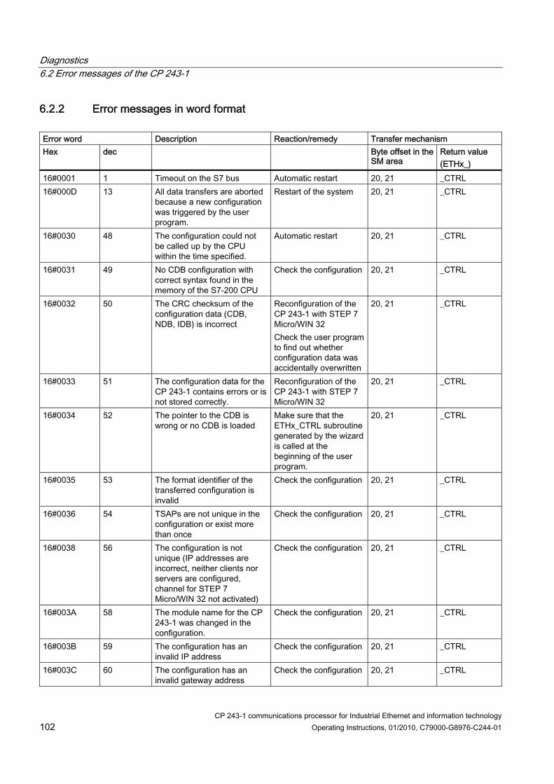
Diagnostics 6.2 Error messages of the CP 243-1
CP 243-1 communications processor for Industrial Ethernet and information technology 102 Operating Instructions, 01/2010, C79000-G8976-C244-01
6.2.2 Error messages in word format Error word Description Reaction/remedy Transfer mechanism Hex dec Byte offset in the
SM area Return value (ETHx_)
16#0001 1 Timeout on the S7 bus Automatic restart 20, 21 _CTRL 16#000D 13 All data transfers are aborted
because a new configuration was triggered by the user program.
Restart of the system 20, 21 _CTRL
16#0030 48 The configuration could not be called up by the CPU within the time specified.
Automatic restart 20, 21 _CTRL
16#0031 49 No CDB configuration with correct syntax found in the memory of the S7-200 CPU
Check the configuration 20, 21 _CTRL
16#0032 50 The CRC checksum of the configuration data (CDB, NDB, IDB) is incorrect
Reconfiguration of the CP 243-1 with STEP 7 Micro/WIN 32 Check the user program to find out whether configuration data was accidentally overwritten
20, 21 _CTRL
16#0033 51 The configuration data for the CP 243-1 contains errors or is not stored correctly.
Reconfiguration of the CP 243-1 with STEP 7 Micro/WIN 32
20, 21 _CTRL
16#0034 52 The pointer to the CDB is wrong or no CDB is loaded
Make sure that the ETHx_CTRL subroutine generated by the wizard is called at the beginning of the user program.
20, 21 _CTRL
16#0035 53 The format identifier of the transferred configuration is invalid
Check the configuration 20, 21 _CTRL
16#0036 54 TSAPs are not unique in the configuration or exist more than once
Check the configuration 20, 21 _CTRL
16#0038 56 The configuration is not unique (IP addresses are incorrect, neither clients nor servers are configured, channel for STEP 7 Micro/WIN 32 not activated)
Check the configuration 20, 21 _CTRL
16#003A 58 The module name for the CP 243-1 was changed in the configuration.
Check the configuration 20, 21 _CTRL
16#003B 59 The configuration has an invalid IP address
Check the configuration 20, 21 _CTRL
16#003C 60 The configuration has an invalid gateway address
Check the configuration 20, 21 _CTRL

Diagnostics 6.2 Error messages of the CP 243-1
CP 243-1 communications processor for Industrial Ethernet and information technology Operating Instructions, 01/2010, C79000-G8976-C244-01 103
Error word Description Reaction/remedy Transfer mechanism Hex dec Byte offset in the
SM area Return value (ETHx_)
16#003D 61 The configuration has an invalid value in the keepalive parameter
Check the configuration 20, 21 _CTRL
16#003E 62 No valid configuration received from memory of the S7-200 CPU or from BOOTP/DHCP
Cyclic attempt to obtain a valid configuration either from the memory of the S7-200 CPU or via a BOOTP/DHCP server
20, 21 _CTRL
16#0042 66 The NDB contains syntax errors in the read/write requests or length information.
Check the configuration 20, 21 _CTRL
16#0093 147 The BOOTP/DHCP request failed
Automatic restart 20, 21 _CTRL
16#0094 148 The reply of the BOOTP/DHCP server contains invalid data
Automatic restart 20, 21 _CTRL
16#0095 149 The TCP/IP stack did not accept the specified monitoring time (keepalive).
Automatic restart 20, 21 _CTRL
16#0096 150 The TCP/IP stack did not accept the IP address specified for a client.
Automatic restart 20, 21 _CTRL
16#0097 151 The TCP/IP stack did not accept the specified subnet mask.
Automatic restart
20, 21 _CTRL
16#0098 152 The TCP/IP stack did not accept the specified gateway address.
Automatic restart
20, 21 _CTRL
16#00B0 176 The IDB contains invalid values.
Create configuration with STEP 7 Micro/WIN 32
20, 21 _CTRL
16#00B1 177 The CRC check of the IDB failed.
Create configuration with STEP 7 Micro/WIN 32 Check the user program to find out whether configuration data was accidentally overwritten
20, 21 _CTRL
16#00B2 178 No administrator name is specified in the IDB.
Create configuration with STEP 7 Micro/WIN 32
20, 21 _CTRL
16#00B3 179 The administrator password check failed or no password was specified
Create configuration with STEP 7 Micro/WIN 32
20, 21 _CTRL
16#00B7 183 The administrator password is too short.
Create configuration with STEP 7 Micro/WIN 32
20, 21 _CTRL

Diagnostics 6.2 Error messages of the CP 243-1
CP 243-1 communications processor for Industrial Ethernet and information technology 104 Operating Instructions, 01/2010, C79000-G8976-C244-01
Error word Description Reaction/remedy Transfer mechanism Hex dec Byte offset in the
SM area Return value (ETHx_)
16#00BB 187 Bad IDB format Create configuration with STEP 7 Micro/WIN 32
20, 21 _CTRL
16#00BD 189 Initialization of the file system failed
Delete files from the file system
20, 21 _CTRL
16#00BF 191 System files could not be set up in the file system
Delete files from the file system
20, 21 _CTRL
16#00F0 240 The S7-200 CPU failed to recognize the CP 243-1
Check configuration and structure of the S7-200 system
_CTRL
16#00F1 241 The address of the output byte via which the CP 243-1 is supposed to be accessible according to the configuration is not compatible with the current position of the CP 243-1 in the S7-200 system.
Check configuration and structure of the S7-200 system
_CTRL
16#0100 bis 16#0108
256 bis 264
Timeout on the S7 bus Automatic restart 20, 21 _CTRL
16#8080 32896 CP 243-1 not yet completely started up.
If necessary, check 24 V supply
20, 21 _CTRL
Error messages in word format
6.2.3 Error messages of the test mechanism for e-mails The error messages of the test routine for e-mails are shown in the Web browser as an error code with explanatory text in English. The errors that can occur here are listed in the table below.
Error code Error text Description 0 E-Mail successful delivered to E-Mail
server Test e-mail sent successfully to e-mail server
1 No valid configuration file No valid e-mail configuration file on the CP 243-1
2 General error Contact hotline if necessary 3 General error Contact hotline if necessary 4 No E-Mail server reachable E-mail server not configured or not
accessible 5 No E-Mail server reachable E-mail server not configured or not
accessible 6 No E-Mail server reachable E-mail server not configured or not
accessible 7 General protocol error Error during transfer with SMTP

Diagnostics 6.2 Error messages of the CP 243-1
CP 243-1 communications processor for Industrial Ethernet and information technology Operating Instructions, 01/2010, C79000-G8976-C244-01 105
Error code Error text Description 8 General protocol error Error during transfer with SMTP 9 General protocol error Error during transfer with SMTP 10 FROM command failed FROM (CP's own e-mail address) not
correctly configured or unknown to e-mail server
11 TO command failed TO addressee not specified correctly or unknown to e-mail server
12 CC command failed CC addressee not specified correctly or unknown to e-mail server
13 General protocol error Error during transfer with SMTP 14 Sending E-Mail failed Error during transfer of the e-mail 15 General protocol error Error during transfer with SMTP 16 Expanding E-Mail text failed Error while expanding e-mail
placeholder in -mail text, check e-mail text configuration
17 Expanding E-Mail text failed Error while expanding e-mail placeholder in -mail text, check e-mail text configuration
18 Expanding E-Mail text failed Error while expanding e-mail placeholder in -mail text, check e-mail text configuration
19 Timeout sending E-Mail Timeout while sending, e-mail server not accessible
20 Test-E-Mail functionality already in use Another user called the test e-mail function at the same time. Try again
21 General error Contact hotline if necessary 22 General error Contact hotline if necessary
Error messages of the test mechanism for e-mails


CP 243-1 communications processor for Industrial Ethernet and information technology Operating Instructions, 01/2010, C79000-G8976-C244-01 107
Appendix A: Technical specifications A Construction: Module format Dimensions (W x H x D) Weight
S7-200 expansion module 71.2 x 80 x 62 mm approx. 150 g
Transmission rate 10 Mbps and 100 Mbps Flash memory size 8 Mbytes as ROM for firmware of the CP 243-1 and 8
Mbytes as ROM for the file system SDRAM memory size 16 Mbytes Guaranteed life of flash memory for the file system 100 000 million write or delete operations Interfaces Connection to Industrial Ethernet (10/100 Mbps)
8-pin RJ-45 jack
Input voltage +24 V DC (-15%/+20%) Current consumption From S7 bus From external 24 V DC
55 mA 60 mA
Power dissipation 1.5 W Max. number of connections Max. of 8 S7 connections (XPUT/XGET or READ/WRITE) +
1 connection to STEP 7 Micro/WIN 32 Max. Max. number of IT connections One connection each for the FTP server, the FTP client and
the e-mail client plus 4 HTTP connections Permissible ambient conditions Operating temperature Transport/storage temperature Max. relative humidity. Operating altitude
0 °C to +55 °C for horizontal installation 0 °C to +45 °C for vertical installation -40 °C to +70 °C 95% at +25 °C Up to 2000 m above sea level. At higher altitudes, cooling may be reduced which then requires a reduction of the maximum operating temperature
Type of protection IP20 Ethernet standard IEEE 802.3

Appendix A: Technical specifications
CP 243-1 communications processor for Industrial Ethernet and information technology 108 Operating Instructions, 01/2010, C79000-G8976-C244-01
Standards / approvals CE mark UL 508 or cULus CSA C22.2, number 142 or cULus FM 3611 EN 50081-2 / EN 61000-6-4 EN 55011 group 1 class A EN 60529 EN 61000-6-2 EN 61131-2
ATEX: EN 60079-0:2006, EN 60079-15:2005 II 3 G Ex nA II T4 KEMA 03 ATEX I228X
Startup time or restart time after a reset approx. 10 seconds Amount of user data as client: with XPUT/XGET: up to 212 bytes
as server: – with XGET or READ: up to 222 bytes – with XPUT or WRITE: up to 212 bytes
Max. e-mail size 1024 characters File system Max. path length incl. file and drive names:
254 characters Max. length of a file name: 99 characters Max. nesting depth of the directories: 49
Server ports used HTTP: 80 FTP command channel: 21 FTP data channel for FTP server: 3100 - 3199 S7 connection establishment: 102
Technical specifications

CP 243-1 communications processor for Industrial Ethernet and information technology Operating Instructions, 01/2010, C79000-G8976-C244-01 109
Appendix B: Example B
Below, you will find an example of how to handle the CP 243-1 as an S7 client. This example shows how to use the subroutines created by the Internet wizard integrated in STEP 7 Micro/WIN 32 at the end of configuration. The data block in which the configuration is stored by the Internet wizard is specified at the end of the program code. The sample program is included on the QuickStart CD for SIMATIC NET along with the configuration as a STEP 7 Micro/WIN 32 project. To run this program you will need Ethernet access to a second S7-200 system on which there is a suitably configured S7 server. The user name for the administrator in the sample program is "root" and the password is "rootroot".
Program code Project name: Example_Client Version: 02.01 Date: 20.01.2003 Target hardware: CPU 224 with CP 243-1 in slot 0 Description: Sample program for communication between two S7-200 stations via Industrial Ethernet. A character string ("CP243") that is stored starting at address VB500 and with a length of 5 bytes is sent from the local S7-200 system to another S7-200 system. It is stored there at the same address and then read back from there. This procedure is repeated continuously. The associated server must be configured as a suitable counterpart. The user program that runs on the server simply has to call up the ETHx_CTRL subroutine. Calls for the ETHx_XFR subroutine are not required for operating the server. The CRC check is enabled. The configuration (IP addresses, …) must be adapted to the current situation. The "CP243" string must be stored starting at address VB500.
NETWORK 1 The ETHT0_CTRL subroutine initializes and monitors the CP 243-1. Status bit SM0.0 is generated at input "EN". This ensures that the subroutine is always activated. As soon as the CP 243-1 has completed startup, the "CP_Ready" and "CH_Ready" outputs are set. If an error occurred in the configuration, the "Error" output is set. The transferred error code is stored in memory word 2. It can be read out in the status table. LD Always_On CALL ETH0_CTRL, cp_ready, ch_ready, cp_error

Appendix B: Example
CP 243-1 communications processor for Industrial Ethernet and information technology 110 Operating Instructions, 01/2010, C79000-G8976-C244-01
Symbol Address Comment Always_On SM0.0 Due the system, always 1 ch_ready MW8 cp_error MW2 cp_ready M0.0 ETH0_CTRL SBR1 This POU was generated by the
Internet wizard for use with CP 243-1
NETWORK 2 As soon as channel 0 is ready for the transfer and "ch0_ready" is set, the "start" variable is set. This may take several cycles. LD ch0_ready Sstart, 1
Symbol Address Comment ch0_ready M8.0 Bit for channel 0 in the CH_READY
return value of the ETH0_CTRL subroutine
start M4.0 Flip flop for automatic start of the data transfer
NETWORK 3 For an S7-200, the "First_Scan_ON" bit is only set in the first cycle for system-related reasons. This resets the "start" variable. This is necessary so that the "start" variable always generates a signal edge for the start of the ETHx_XFR subroutine, even when the CPU starts and stops repeatedly. LD First_Scan_On Rstart, 1
Symbol Address Comment First_Scan_On SM0.1 Due to the system, 1 in the first cycle,
otherwise always 0 start M4.0 Flip flop for automatic start of the data
transfer
NETWORK 4 The local S7-200 station sends data from VB500 (data length of 5 bytes) via the Ethernet connection to another S7-200 station. There the data is stored starting at VB500. The read/write request is only possible after a positive edge at the "START" parameter, when the "Done" bit of any preceding read request is set. The "Done" bit is transferred in the "ch0_done_read" variable. The outputs of the read and write request are linked so that only one request per channel can be processed at any one time. This means that a new request is only initiated after the preceding request is completed.

Appendix B: Example
CP 243-1 communications processor for Industrial Ethernet and information technology Operating Instructions, 01/2010, C79000-G8976-C244-01 111
The "Chan_ID" parameter specifies the number of the channel via which the data access will take place. In the present case, this would be the channel with the number 0. The "Data" parameter specifies the number of the channel-specific block of data. A request that has been initiated could be stopped using the "Abort" parameter. To do this, the M7.0 memory bit must be set. In this example, this memory bit also impacts the read request from Network 5. After M7.0 is cleared, read/write requests are sent again since the "Done" bit is always set along with the "Error" bit after a request is aborted. Applying special memory bit SM0.0 ensures that the ETH0_XFR subroutine is always enabled. As soon as the write request is completed, a 1 is returned in the "Done" return parameter. Any errors that occurred are transferred using by the "Error" parameter. Otherwise, a 0 is returned in this parameter. LD Always_On =L60.0 LD ch0_done_read EU Uch0_ready LD start EU OLD =L63.7 LD L60.0 CALL ETH0_XFR, L63.7, Connection0_0, Write_1, Connection_abort, ch0_done_write, ch0_error_write
Symbol Address Comment Always_On SM0.0 Due the system, always 1 ch0_done_read M5.0 Done bit of the read request ch0_done_write M5.1 Done bit of the write request ch0_error_write MB14 Error memory bit of channel 0, "write"
request ch0_ready M8.0 Bit for channel 0 in the CH_READY
return value of the ETH0_CTRL subroutine
Connection0_0 VB233 Connection_abort M7.0 Transfer aborted ETH0_XFR SBR2 This POU was generated by the
Internet wizard for use with CP 243-1
start M4.0 Flip flop for automatic start of the data transfer
Write_1 VB234
NETWORK 5 The local S7-200 station now reads out data from VB500 of another S7-200 station and stores this starting at VB500 of the local S7-200 station.

Appendix B: Example
CP 243-1 communications processor for Industrial Ethernet and information technology 112 Operating Instructions, 01/2010, C79000-G8976-C244-01
Before the read request is executed, the two variables "ch0_done_write" and "ch0_ready" are evaluated to ensure, firstly, that the preceding write request is completed and, secondly, that the status of channel 0 is "ready". LDAlways_On = L60.0 LDch0_done_write EU U ch0_ready = L63.7 LDL60.0 CALLETH0_XFR, L63.7, Connection0_0, Read_1, Connection_abort, ch0_done_read, ch0_error_read
Symbol Address Comment Always_On SM0.0 Due the system, always 1 ch0_done_read M5.0 Done bit of the read request ch0_done_write M5.1 Done bit of the write request ch0_error_read MB6 Error memory bit of channel 0, "read"
request ch0_ready M8.0 Bit for channel 0 in the CH_READY
return value of the ETH0_CTRL subroutine
Connection0_0 VB233 Connection_abort M7.0 Transfer aborted ETH0_XFR SBR2 This POU was generated by the
Internet wizard for use with CP 243-1 Read_1 VB235
Data block for this configuration // //DATA BLOCK COMMENTS // //Press F1 for help and example data block // //-------------------------------------------------------------------- // CP 243-1 Module Configuration block. Generated by the Internet // Wizard //-------------------------------------------------------------------- VB0'CP243'// Module ID for CP 243-1 module at position 0 VW516#006C// Length of CDB VW716#0014// Length of NPB VB916#81// Configuration Data Version VB10 16#00// Project Configuration Version VW11 16#0000 VW13 16#0004// Auto Detect Communications,User Configured // IP Address, CRC protection enabled. VD15 16#C1012807 // IP Address for module (193.1.40.7) VD19 16#FFFFFF00 // Subnet mask address for module (255.255.255.0)

Appendix B: Example
CP 243-1 communications processor for Industrial Ethernet and information technology Operating Instructions, 01/2010, C79000-G8976-C244-01 113
VD23 16#C1012801 // Gateway Address (193.1.40.1) VW27 30 // Keep Alive Interval in seconds //------------------------------------------ Connection 0 VB29 16#83// Client Connection,Keep Alive Enabled. VD30 16#C1012812 // Address of Server for this connection //(193.1.40.18) VW34 16#1000// Local TSAP for this connection (10.00). VW36 16#1000// Remote TSAP for this connection (10.00). //------------------------------------------ Connection 1 VB38 16#00// Connection not defined. VD39 16#00000000 VW43 16#0000 VW45 16#0000 //------------------------------------------ Connection 2 VB47 16#00// Connection not defined. VD48 16#00000000 VW52 16#0000 VW54 16#0000 //------------------------------------------ Connection 3 VB56 16#00// Connection not defined. VD57 16#00000000 VW61 16#0000 VW63 16#0000 //------------------------------------------ Connection 4 VB65 16#00// Connection not defined. VD66 16#00000000 VW70 16#0000 VW72 16#0000 //------------------------------------------ Connection 5 VB74 16#00// Connection not defined. VD75 16#00000000 VW79 16#0000 VW81 16#0000 //------------------------------------------ Connection 6 VB83 16#00// Connection not defined. VD84 16#00000000 VW88 16#0000 VW90 16#0000 //------------------------------------------ Connection 7 VB92 16#00// Connection not defined. VD93 16#00000000 VW97 16#0000 VW99 16#0000 //----------------------------- STEP 7-Micro/WIN reserved connection. VB10116#82 VD10216#00000000 VW10616#A9A8 //-------------------------------------------------------------------- // Network Parameter Block Section // This section is used by the CP 243-1 Module //-------------------------------------------------------------------- VW10816#0000

Appendix B: Example
CP 243-1 communications processor for Industrial Ethernet and information technology 114 Operating Instructions, 01/2010, C79000-G8976-C244-01
VD11016#00000000 VD11416#00000000 VD11816#00000000 VB12216#00 VB12316#00 VB12416#00 VB12516#00 VB12616#00 VB12716#00 //-------------------------------------------------------------------- // Network Data Block Section //-------------------------------------------------------------------- VW12816#0026 VB13016#00 VB13116#03 VB13216#0F VB13316#0F VB134'W=5,VB500,VB500' // Message 0 for Connection 0. VB149'R=5,VB500,VB500' // Message 1 for Connection 0. VW16416#D0C3 //-------------------------------------------------------------------- //Internet Data Block Section //-------------------------------------------------------------------- VW16616#0043 VB16816#32 VB16916#02 VB17016#02 VB17116#02 VB17216#02 VB17316#81 VB17416#00 //Administrator Web access flag VB175'root$00$00$00$00$00$00$00$00$00$00$00$00'//Administrator Login VB191'R33~R33~$00$00$00$00$00$00$00$00$00$00$00$00$00$00$00$00$00$00$00$00$00$00$00$00' //Administrator Password VW22316#0000 //SMTP Client enable flag VW22516#0000 //FTP Client enable flag VW22716#0000 VW22916#0000//HTTP Server enable flag VW23116#9E28 //-------------------------------------------------------------------- //Symbol Initializations //-------------------------------------------------------------------- VB2330 VB2340 VB2351 //-------------------------------------------------------------------- VB500'CP243'// Module ID for testing

CP 243-1 communications processor for Industrial Ethernet and information technology Operating Instructions, 01/2010, C79000-G8976-C244-01 115
Appendix C - Timeouts C
The values in the following tables represent times after which the the related actions must have been triggered.
On Ethernet Meaning Action if timeout occurs Fixed set time in seconds Maximum wait time after which a frame must be completely received via TCP/IP.
Reject frame fragment. CP shuts down the connection
3
Maximum wait time after which a frame must be completely sent via TCP/IP.
Abort sending. CP shuts down the connection
3
Maximum wait time of the CP until a request sent to the CPU by an external client is replied to by the CPU.
Reject action. CP waits for new requests. Client receives no response
60
Logout time when all channels are busy and MW is not yet connected. (So that MW can always establish a connection)
Oldest of the connected TCP/IP servers that could not yet be assigned via TSAP interrupts the connection and waits for a new connection to be established
60
Interval at which incoming connection establishment requests are processed.
Delay of the next connection establishment
1
Wait time after an unsuccessful attempt by a client to establish a connection
Attempt to establish a connection is repeated
10
Wait time of a client for confirmation of a request to establish a connection
Client shuts down the connection and connects again
6
Maximum time for a successful BOOTP/DHCP request
Renewed attempt to obtain a valid configuration either from the memory of the S7-200 CPU or via a BOOTP/DHCP server
24 attempts at intervals of 2.5 seconds = 60 seconds
Maximum wait time for confirmation of sending the test e-mail
The e-mail is not transferred, an error message to this effect is returned.
30
Idle time of an FTP connection. When this time expires, the connection is terminated by the FTP server if a new FTP client wants to establish a connection
Termination of existing FTP connection and establishment of a new FTP connection to the new FTP client
60
Maximum wait time of the FTP server for the establishment of a data connection
The FTP client not establish a data connection.
90
Timeouts on Ethernet

Appendix C - Timeouts
CP 243-1 communications processor for Industrial Ethernet and information technology 116 Operating Instructions, 01/2010, C79000-G8976-C244-01
On the S7 bus Meaning Action if timeout occurs Fixed set time in seconds Maximum time for one communication cycle between the CP 243-1 and the S7-200 CPU via the S7 bus Note: Three cycle times are usually required per read/write request in the client use case, one cycle time is required in the server use case. Long execution times of the read/write requests must be expected with user programs which require an extreme amount of time and simultaneous communication via a lot of channels.
Request rejected, CP 243-1 restarts 10 (per cycle)
Timeout for the successful transfer of CDB/NDB when CP starts up
CP 243-1 restarts 120
Time after which S7 CPU must detect the CP 243-1 physically during a CPU restart
CP 243-1 restarts 1
Maximum time by which the configured e-mail server must have accepted a connection establishment request.
Connection is not established, the CP 243-1 reports an error
20
Maximum time by which a configured FTP server must have accepted a connection establishment request.
Connection is not established, the CP 243-1 reports an error
20
Timeouts on the S7 bus
On the user interface Meaning Action if timeout occurs Fixed set time in seconds Latest time after which an error or message code is returned by the ETHx_CTRL subroutine with the Error return parameter, must be reset by the CP 243-1. This code is also always located in the SM memory area used by the CP 243-1 in the two bytes with the offset 20 and 21
Error or message code is set to 0 60

CP 243-1 communications processor for Industrial Ethernet and information technology Operating Instructions, 01/2010, C79000-G8976-C244-01 117
Appendix D - Compatibility D
Standard (STEP 7) supported access from S7-300/400 clients to: S7-200 with CPU222, CPU224, CPU 226/XM CPU firmware version <1.21 1.21 >1.21 Data types BOOL √ √ √ BYTE √ √ √ CHAR X RO √ WORD √ √ √ INT X RO √ DWORD √ √ √ DINT X RO √ REAL X RO √ Memory areas INPUT √ √ √ OUTPUT √ √ √ BIT MEMORY √ √ √ DATA BLOCK VARIABLES* √ √ √ ANALOG INPUT SPECIAL MEMORY
Character Meaning √ supported not generally supported X not possible if CPU with this firmware version is used RO "read-only access" * The access to VBxx should be formulated as DB1.DBBxx (standard STEP 7)
STEP 7 Micro/WIN 32 wizard supported CP 243-1 access as client to... S7-300/400 S7-200 with CPU222, CPU224, CPU 226/XM CPU firmware version <1.21 1.21 >1.21 Data types BOOL BYTE √ √ √ √

Appendix D - Compatibility
CP 243-1 communications processor for Industrial Ethernet and information technology 118 Operating Instructions, 01/2010, C79000-G8976-C244-01
S7-300/400 S7-200 with CPU222, CPU224, CPU 226/XM CHAR WORD INT DWORD DINT REAL COUNTER TIMER Memory areas INPUT √ √ √ √ OUTPUT √ √ √ √ BIT MEMORY √ √ √ √ DATA BLOCK √ VARIABLES √ √ √ ANALOG INPUT SPECIAL MEMORY S7 COUNTER S7 TIMER
Character Meaning √ supported not generally supported X not possible if CPU with this firmware version is used
JAVA Beans supported CP 243-1 access to... (The JAVA Beans are a shared package for SIMATIC 200/300/400 communications processors)
S7-300/400 S7-200 with CPU222, CPU224, CPU 226/XM CPU firmware version <1.21 1.21 >1.21 Data types BOOL √ √ √ √ BYTE √ √ √ √ CHAR √ X RO √ WORD √ √ √ √ INT √ X RO √ DWORD √ √ √ √ DINT √ X RO √ REAL √ X RO √ COUNTER √ TIMER √

Appendix D - Compatibility
CP 243-1 communications processor for Industrial Ethernet and information technology Operating Instructions, 01/2010, C79000-G8976-C244-01 119
S7-300/400 S7-200 with CPU222, CPU224, CPU 226/XM Memory areas INPUT √ √ √ √ OUTPUT √ √ √ √ BIT MEMORY √ √ √ √ DATA BLOCK √ VARIABLES √ √ √ ANALOG INPUT SPECIAL MEMORY √
(RO up to address 30)
√ (RO up to
address 30)
√ (RO up to
address 30) S7 COUNTER √ S7 TIMER √
Character Meaning √ supported not generally supported X not possible if CPU with this firmware version is used RO "read-only access"
E-MAIL tags (STEP 7 Micro/WIN 32 wizard) supported access to... S7-200 with CPU222, CPU224, CPU 226/XM CPU firmware version <1.21 1.21 >1.21 Data types BOOL BYTE RO RO RO CHAR WORD RO RO RO INT DWORD RO RO RO DINT REAL Memory areas INPUT RO RO RO OUTPUT RO RO RO BIT MEMORY RO RO RO DATA BLOCK VARIABLES RO RO RO ANALOG INPUT RO / word RO / word RO / word SPECIAL MEMORY RO RO RO

Appendix D - Compatibility
CP 243-1 communications processor for Industrial Ethernet and information technology 120 Operating Instructions, 01/2010, C79000-G8976-C244-01
Character Meaning √ supported not generally supported X not possible if CPU with this firmware version is used RO "read-only access" RO / word "read-only access", but only as WORD access
SIMATIC NET OPC supported access to... S7-200 with CPU222, CPU224, CPU 226/XM CPU firmware version Data types BOOL √ √ √ BYTE √ √ √ CHAR X RO √ WORD √ √ √ INT X RO √ DWORD √ √ √ DINT X RO √ REAL X RO √ Access to data areas INPUT √ √ √ OUTPUT √ √ √ BIT MEMORY √ √ √ DATA BLOCK VARIABLES* √ √ √ ANALOG INPUT SPECIAL MEMORY
Character Meaning √ supported not generally supported X not possible if CPU with this firmware version is used RO "read-only access" * The access to VBxx should be formulated as DB1.DBBxx (standard STEP 7)