Embed Size (px)
Citation preview

CP-2232E Remote Control Panel
User Guide © Copyright 2010 - 2013 EVERTZ MICROSYSTEMS LTD. 5288 John Lucas Drive, Burlington, Ontario, Canada L7L 5Z9 Phone: +1 905-335-3700 Sales Fax: +1 905-335-3573 Tech Support Phone: +1 905-335-7570 Tech Support Fax: +1 905-335-7571 Internet: Sales: [email protected] Tech Support: [email protected] Web Page: http://www.evertz.com Version 1.1 July 2013 The material contained in this manual consists of information that is the property of Evertz Microsystems and is intended solely for the use of purchasers of the CP-2232E. Evertz Microsystems expressly prohibits the use of this manual for any purpose other than the operation of the device. All rights reserved. No part of this publication may be reproduced without the express written permission of Evertz Microsystems Ltd. Copies of this guide can be ordered from your Evertz products dealer or from Evertz Microsystems.


IMPORTANT SAFETY INSTRUCTIONS
The lightning flash with arrowhead symbol within an equilateral triangle is intended to alert the user to the presence of uninsulated “Dangerous voltage” within the product’s enclosure that may be of sufficient magnitude to constitute a risk of electric shock to persons.
The exclamation point within an equilateral triangle is intended to alert the user to the presence of important operating and maintenance (Servicing) instructions in the literature accompanying the product.
• Read these instructions • Keep these instructions. • Heed all warnings. • Follow all instructions. • Do not use this apparatus near water. • Clean only with dry cloth. • Do not block any ventilation openings. Install in accordance with the manufacturer’s instructions. • Do not install near any heat sources such as radiators, heat registers, stoves, or other apparatus
(including amplifiers) that produce heat. • Do not defeat the safety purpose of the polarized or grounding-type plug. A polarized plug has
two blades with one wider than other. A grounding-type plug has two blades and a third grounding prong. The wide blade or the third prong is provided for your safety. If the provided plug does not fit into your outlet, consult an electrician for replacement of the obsolete outlet.
• Protect the power cord from being walked on or pinched particularly at plugs, convenience receptacles and the point where they exit from the apparatus.
• Only use attachments/accessories specified by the manufacturer. • Unplug this apparatus during lightning storms or when unused for long periods of time. • Refer all servicing to qualified service personnel. Servicing is required when the apparatus has
been damaged in any way, such as power-supply cord or plug is damaged, liquid has been spilled or objects have fallen into the apparatus, the apparatus has been exposed to rain or moisture, does not operate normally, or has been dropped.
WARNING TO REDUCE THE RISK OF FIRE OR ELECTRIC – SHOCK, DO NOT EXPOSE THIS APPARATUS TO RAIN OR MOISTURE.
WARNING DO NOT EXPOSE THIS EQUIPMENT TO DRIPPING OR SPLASHING AND ENSURE THAT NO OBJECTS FILLED WITH LIQUIDS ARE PLACED ON THE EQUIPMENT.
WARNING TO COMPLETELY DISCONNECT THIS EQUIPMENT FROM THE AC MAINS, DISCONNECT THE POWER SUPPLY CORD PLUG FROM THE AC RECEPTACLE.
WARNING THE MAINS PLUG OF THE POWER SUPPLY CORD SHALL REMAIN READILY OPERABLE.

INFORMATION TO USERS IN EUROPE
NOTE
This equipment with the CE marking complies with both the EMC Directive (2004/108/EC) and the Low Voltage Directive (2006/95/EC) issued by the Commission of the European Community. Compliance with these directives implies conformity to the following European standards:
• EN60065 Product Safety • EN55103-1 Electromagnetic Interference Class A (Emission) • EN55103-2 Electromagnetic Susceptibility (Immunity)
This equipment has been tested and found to comply with the limits for a Class A digital device, pursuant to the European Union EMC directive. These limits are designed to provide reasonable protection against harmful interference when the equipment is operated in a commercial environment. This equipment generates, uses, and can radiate radio frequency energy and, if not installed and used in accordance with the instruction manual, may cause harmful interference to radio communications. Operation of this equipment in a residential area is likely to cause harmful interference in which case the user will be required to correct the interference at his own expense.
INFORMATION TO USERS IN THE U.S.A. NOTE
FCC CLASS A DIGITAL DEVICE OR PERIPHERAL
This equipment has been tested and found to comply with the limits for a Class A digital device, pursuant to Part 15 of the FCC Rules. These limits are designed to provide reasonable protection against harmful interference when the equipment is operated in a commercial environment. This equipment generates, uses, and can radiate radio frequency energy and, if not installed and used in accordance with the instruction manual, may cause harmful interference to radio communications. Operation of this equipment in a residential area is likely to cause harmful interference in which case the user will be required to correct the interference at his own expense.
WARNING
Changes or modifications not expressly approved by Evertz Microsystems Ltd. could void the user’s authority to operate the equipment. Use of unshielded plugs or cables may cause radiation interference. Properly shielded interface cables with the shield connected to the chassis ground of the device must be used.
EN60065 Safety
EN504192 2005 Waste electrical products should not
be disposed of with household waste. Contact your Local Authority
for recycling advice
EN55103-1: 1996 Emission EN55103-2: 1996 Immunity
Evertz Microsystems Ltd This device complies with part 15 of the FCC Rules. Operation is subject to the following two conditions: This device may cause harmful interference, and this device must accept any interference received, including interference that may cause undesired operation.
Tested to comply with FCC Standards
For Commercial Use

CP-2232E Remote Control Panel
Revision 1.1
REVISION HISTORY
REVISION DESCRIPTION DATE 1.0 First Release May 2010 1.1 Added “Navigating the Control Panel” section July 2013 Information contained in this manual is believed to be accurate and reliable. However, Evertz assumes no responsibility for the use thereof nor for the rights of third parties, which may be affected in any way by the use thereof. Any representations in this document concerning performance of Evertz products are for informational use only and are not warranties of future performance, either expressed or implied. The only warranty offered by Evertz in relation to this product is the Evertz standard limited warranty, stated in the sales contract or order confirmation form. Although every attempt has been made to accurately describe the features, installation and operation of this product in this manual, no warranty is granted nor liability assumed in relation to any errors or omissions unless specifically undertaken in the Evertz sales contract or order confirmation. Information contained in this manual is periodically updated and changes will be incorporated into subsequent editions. If you encounter an error, please notify Evertz Customer Service department. Evertz reserves the right, without notice or liability, to make changes in equipment design or specifications.

CP-2232E Remote Control Panel
Revision 1.1
This page left intentionally blank

CP-2232E Remote Control Panel
Revision 1.1 Page i
TABLE OF CONTENTS
1. OVERVIEW ......................................................................................................................... 1
2. INSTALLATION ................................................................................................................... 2
2.1. REAR PANEL ........................................................................................................................ 2
2.2. FRONT CONTROL PANEL ................................................................................................... 2
2.3. POWER CONNECTIONS ...................................................................................................... 3
2.4. MOUNTING ........................................................................................................................... 4
3. TECHNICAL DESCRIPTION ............................................................................................... 5
3.1. SPECIFICATIONS ................................................................................................................. 5
3.1.1. Control ........................................................................................................................ 5 3.1.2. Electrical ..................................................................................................................... 5 3.1.3. Physical ...................................................................................................................... 5 3.1.4. Compliance ................................................................................................................ 5
3.2. SERVICING INSTRUCTIONS ................................................................................................ 5
4. FRONT PANEL CONTROL ................................................................................................. 6
4.1. FRONT PANEL NAVIGATION OPTIONS .............................................................................. 6
4.2. UPGRADING ......................................................................................................................... 6
4.3. CONFIGURING THE NETWORK SETTINGS ........................................................................ 7
4.4. TESTING THE PANEL’S FUNCTIONALITY .......................................................................... 7
4.4.1. Key Test ..................................................................................................................... 7 4.4.2. LCD Test .................................................................................................................... 8 4.4.3. Touchscreen Test ....................................................................................................... 8 4.4.4. GPIO Test .................................................................................................................. 8
4.5. CHECKING THE STATUS OF THE PANEL .......................................................................... 8
5. SYSTEM CONFIGURATION ............................................................................................... 9
5.1. UPGRADING THE CP-2232E PANEL ................................................................................... 9
5.1.1. Requirements ............................................................................................................. 9 5.1.2. Getting Started ........................................................................................................... 9 5.1.3. Upgrading Firmware on the CP-2232E ....................................................................... 9
5.2. SYSTEMS MENU ................................................................................................................ 11

CP-2232E Remote Control Panel
Page ii Revision 1.1
5.2.1. Products Page .......................................................................................................... 11 5.2.1.1. Products Uploaded ..................................................................................... 12
5.2.2. Service Templates Page .......................................................................................... 12 5.2.2.1. Service Template Controls ......................................................................... 14 5.2.2.2. Service Template Parameter Tree .............................................................. 15 5.2.2.3. Template Properties ................................................................................... 16 5.2.2.4. Creating a New Service Template .............................................................. 17 5.2.2.5. Service Template Controls ......................................................................... 18
5.2.3. Services Page .......................................................................................................... 18 5.2.3.1. Service Controls ......................................................................................... 20 5.2.3.2. Available Service Templates ....................................................................... 20 5.2.3.3. Service Properties ...................................................................................... 21 5.2.3.4. Add a Service Template to the Service List ................................................ 21
5.2.4. Systems Page .......................................................................................................... 21 5.2.4.1. Device Properties ....................................................................................... 22
5.3. DISCOVERY MENU ............................................................................................................ 23
5.3.1. Settings Page ........................................................................................................... 24 5.3.2. Ranged Discovery Page ........................................................................................... 25 5.3.3. Import Device Labels ................................................................................................ 26 5.3.4. VistaLINK® Alarm Server .......................................................................................... 27
5.4. SOURCE PROC MENU ....................................................................................................... 27
5.4.1. Source Proc Page .................................................................................................... 28 5.4.2. Destination Proc Page .............................................................................................. 29 5.4.3. Macros Page ............................................................................................................ 29
5.5. HELP MENU ........................................................................................................................ 30
5.5.1. Help Page ................................................................................................................ 30 5.5.1.1. Panel Version ............................................................................................. 31 5.5.1.2. Product Support .......................................................................................... 31 5.5.1.3. Configuration .............................................................................................. 31 5.5.1.4. Logs Tab .................................................................................................... 33
5.5.2. Preferences Page ..................................................................................................... 34 5.5.2.1. Visual Settings ............................................................................................ 34
5.5.3. Import/Export Page .................................................................................................. 35
5.6. UPGRADE MENU ................................................................................................................ 36
6. ADDING AN EVERTZ SYSTEM TO CONTROL ............................................................... 37
6.1. CP-2232E CONTROL OF MVP SYSTEM ............................................................................ 37
6.2. ADDING SNMP SERVICES ................................................................................................. 39
6.3. ADDING AN EQX SERVER ................................................................................................. 40
6.4. CREATING SOURCE-SERVICE MAPPING ........................................................................ 41
7. NAVIGATING THE CONTROL PANEL ............................................................................ 42
7.1. SOURCE (SRC) BUTTON ................................................................................................... 42

CP-2232E Remote Control Panel
Revision 1.1 Page iii
7.2. DESTINATION (DST) BUTTON ........................................................................................... 44
7.3. UP & DOWN ARROWS ....................................................................................................... 45
7.4. CLEAR NEXT SOURCE BUTTON ....................................................................................... 46
7.5. LEVEL BUTTON .................................................................................................................. 47
7.6. SELECTING THE “MORE” BUTTON .................................................................................. 49
Figures
Figure 1-1: CP-2232E Control Panel ............................................................................................. 1 Figure 2-1: CP2232E Rear Panel .................................................................................................. 2 Figure 2-2: CP-2232E Front Control Panel .................................................................................... 3 Figure 5-1: CP2232e Web Interface .............................................................................................. 9 Figure 5-2: Install Firmware Page ................................................................................................ 10 Figure 5-3: Systems Drop Down Menu ........................................................................................ 11 Figure 5-4: Products Page ........................................................................................................... 11 Figure 5-5: Systems – Service Template Page ............................................................................ 12 Figure 5-6: Service Template List ................................................................................................ 13 Figure 5-7: Customizing a Template ............................................................................................ 14 Figure 5-8: Parameter Tree ......................................................................................................... 16 Figure 5-9: New Template Page .................................................................................................. 17 Figure 5-10: Assigning a Parameter ............................................................................................ 18 Figure 5-11: Services List ............................................................................................................ 19 Figure 5-12: Customizing a Service ............................................................................................. 20 Figure 5-13: Systems Page ......................................................................................................... 21 Figure 5-14: New System Window ............................................................................................... 22 Figure 5-15: Update System Window .......................................................................................... 23 Figure 5-16: Discovery Menu ....................................................................................................... 24 Figure 5-17: Settings Page .......................................................................................................... 24 Figure 5-18: Ranged Discovery Page .......................................................................................... 25 Figure 5-19: Import Device Labels Page...................................................................................... 26 Figure 5-20: VistaLINK® Alarm Server ......................................................................................... 27 Figure 5-21: Source Proc Menu ................................................................................................... 27 Figure 5-22: Source Proc Page ................................................................................................... 28 Figure 5-23: Destination Proc Page ............................................................................................. 29 Figure 5-24: Macros Page ........................................................................................................... 29 Figure 5-25: Help Menu ............................................................................................................... 30 Figure 5-26: Help Page ............................................................................................................... 30 Figure 5-27: Product Support Tab ............................................................................................... 31 Figure 5-28: Configuration Tab .................................................................................................... 32 Figure 5-29: Opening config.cf Dialog Box .................................................................................. 32 Figure 5-30: Logs Tab ................................................................................................................. 33 Figure 5-31: Opening logs.lf Dialog Box ...................................................................................... 33 Figure 5-32: Preferences Page .................................................................................................... 34 Figure 5-33: Import/Export Page ................................................................................................. 35 Figure 5-34: Install Firmware Page .............................................................................................. 36 Figure 6-1: Systems Page ........................................................................................................... 37 Figure 6-2: Create a MVP System ............................................................................................... 38 Figure 6-3: Create a SNMP Service............................................................................................. 39
CP-2232E Remote Control Panel
Page iv Revision 1.1
Figure 6-4: Add EQX Server ........................................................................................................ 40 Figure 7-1: Front Panel Display ................................................................................................... 42 Figure 7-2: SRC Layout ............................................................................................................... 42 Figure 7-3: SRC Keypad Display ................................................................................................. 43 Figure 7-4: DST Layout ............................................................................................................... 44 Figure 7-5: DST Keypad Display ................................................................................................. 44 Figure 7-6: Up & Down Arrows Display ........................................................................................ 45 Figure 7-7: Clear Next Source Button .......................................................................................... 46 Figure 7-8: Level Button Display .................................................................................................. 47 Figure 7-9: Selecting the Video Button ........................................................................................ 47 Figure 7-10: Select the ALL Button .............................................................................................. 48 Figure 7-11: Selecting the BREAK AWAY Button ........................................................................ 48 Figure 7-12: Selecting the “MORE” Button .................................................................................. 49 Figure 7-13: Selecting the “CHNG PRFL” Button ........................................................................ 49 Figure 7-14: Selecting the “INFO” Button .................................................................................... 50 Figure 7-15: Selecting the “SRC INFO” Button ............................................................................ 50 Figure 7-16: Selecting the “ENABLE TOGGLE” Button ............................................................... 51 Figure 7-17: Selecting the “LOCK DST” Button ........................................................................... 51 Figure 7-18: Selecting the “PROTECT” Button ............................................................................ 52 Figure 7-19: Selecting the “TIELINES” Button ............................................................................. 52 Figure 7-20: Selecting the “ONE DST VIEW” Button ................................................................... 53 Figure 7-21: Selecting the “TAKE” Button .................................................................................... 53 Figure 7-22: Selecting the “TOGGLE TAKE” Button .................................................................... 54 Figure 7-23: Selecting the “SALVO” Button ................................................................................. 54
Tables Table 5-1: Service Template Buttons ........................................................................................... 13 Table 5-2: Service Template Buttons ........................................................................................... 19 Table 5-3: Service Template Buttons ........................................................................................... 22
CP-2232E Remote Control Panel
Revision 1.1 Page 1
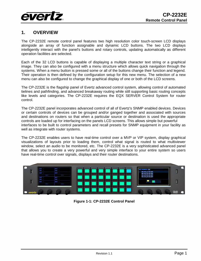
1. OVERVIEW
The CP-2232E remote control panel features two high resolution color touch-screen LCD displays alongside an array of function assignable and dynamic LCD buttons. The two LCD displays intelligently interact with the panel's buttons and rotary controls, updating automatically as different operation facilities are selected. Each of the 32 LCD buttons is capable of displaying a multiple character text string or a graphical image. They can also be configured with a menu structure which allows quick navigation through the systems. When a menu button is pressed some or all of the buttons change their function and legend. Their operation is then defined by the configuration setup for this new menu. The selection of a new menu can also be configured to change the graphical display of one or both of the LCD screens. The CP-2232E is the flagship panel of Evertz advanced control system, allowing control of automated tielines and pathfinding, and advanced breakaway routing while still supporting basic routing concepts like levels and categories. The CP-2232E requires the EQX SERVER Control System for router control. The CP-2232E panel incorporates advanced control of all of Evertz's SNMP enabled devices. Devices or certain controls of devices can be grouped and/or ganged together and associated with sources and destinations on routers so that when a particular source or destination is used the appropriate controls are loaded up for interfacing on the panels LCD screens. This allows simple but powerful interfaces to be built to control parameters and recall presets for SNMP equipment in your facility as well as integrate with router systems. The CP-2232E enables users to have real-time control over a MVP or VIP system, display graphical visualizations of layouts prior to loading them, control what signal is routed to what multiviewer window, select an audio to be monitored, etc. The CP-2232E is a very sophisticated advanced panel that allows you to create a very powerful and very simple interface to your entire system so users have real-time control over signals, displays and their router destinations.
Figure 1-1: CP-2232E Control Panel

CP-2232E Remote Control Panel
Page 2 Revision 1.1
2. INSTALLATION
2.1. REAR PANEL
Figure 2-1 shows the rear view of the CP-2232E control panel. The following is a list of the ports and controls on the rear panel:
USB12VDC
SERIAL A SERIAL B JOYSTICK/GPIO
ETHERNET A10/100/1000
ETHERNET B10/100
ACT LINKACT LINK
Figure 2-1: CP2232E Rear Panel SERIAL A & B: Serial A & B connectors provide RS-232/RS-422 serial control ports. ETHERNET (A & B): These RJ45 connectors are used for Network connections to the CP-2232E. USB (A & B): These USB 2.0 Ports are used for USB-based mouse and/or keyboard
connections to the CP-2232E. JOYSTICK/GPIO: This connector is currently not supported. 12VDC: Two external 12 VDC inputs can used to provide fully redundant powering of the unit. The DC input connector is a 0.218 inch diameter center positive miniature DC power jack.
To connect the 12 VDC supply use an AC to DC converter rated at 12 VDC, 3 A minimum. A power supply converter can be ordered from your Evertz Products dealer (Evertz part # VSHES34-120300). The DC cable of the voltage adapter should be connected to the DC power jack on the rear panel. The voltage adapter DC connector-fastening collar can be screwed to the DC power jack to prevent accidental disconnection.
2.2. FRONT CONTROL PANEL
There are two LCD touch-screen displays located on the front control panel. When operating the panel, content can be selected and displayed on these screens. The group of buttons located in the center of the CP-2232E front control panel are used navigation and selection.

CP-2232E Remote Control Panel
Revision 1.1 Page 3
D1 D2
L1 L2 L3 L4 L5 L6 L7 L8
L9 L10 L11 L12 L13 L14 L15 L16
L17 L18 L19 L20 L21 L22 L23 L24
L25 L26 L27 L28 L29 L30 L31 L32S1 S2 S3 S4 S5 S6 S7 S8
U1
U2
U3
U4
Figure 2-2: CP-2232E Front Control Panel Please note that the labels in Figure 2-2 will NOT be displayed on the front panel of your CP-2232E device. The labels listed above are for reference purposes only when describing the panel controls in the following sections of the manual. The following chart describes the label and function of the associated button. Label(s) Description
D1 & D2 These labels identify the two display screens on the CP-2232E front panel. When operating the panel, the content will be displayed on these screens.
L1 to L32 There are thirty-two LCD buttons located on the front panel, which are labelled L1 to L32 in Figure 2-2.
S1 to S8 S1 to S8 identifies the eight shaft encoders that are available on the front panel. The user can adjust parameters or toggle through items by turning the shaft encoder knobs left and right. The user can also select items by pressing in the shaft encoder.
U1 to U4 There are four USB ports located on the front panel, which are labelled U1 to U4 in Figure 2-2. These ports are used for USB-based mouse and/or keyboard connections, and local upgrading of the panel.
2.3. POWER CONNECTIONS
The CP-2232E comes with an auto-ranging DC voltage adapter that automatically senses the input voltage. Power should be applied by connecting a 3-wire grounding type power supply cord to the power entry module on the DC voltage adapter. The power cord should be minimum 18 AWG wire size; type SVT marked VW-1, maximum 2.5 m in length. The DC cable of the voltage adapter should be connected to the DC power jack on the rear of the panel.
CAUTION: TO REDUCE THE RISK OF ELECTRIC SHOCK, GROUNDING OF THE GROUND PIN OF THE MAINS PLUG MUST BE MAINTAINED.

CP-2232E Remote Control Panel
Page 4 Revision 1.1
2.4. MOUNTING
The CP-2232E is equipped with rack mounting angles and fits into a standard 19 inch by 3.5 inch by 1.2 inch (483 mm x 89 mm x 32mm) rack space. Cooling is achieved by passive air flow across and through the panel chassis.

CP-2232E Remote Control Panel
Revision 1.1 Page 5
3. TECHNICAL DESCRIPTION
3.1. SPECIFICATIONS
3.1.1. Control
Ethernet: 10/100 base T.RJ45 connector Joystick: Parallel contact closure TTL levels, D9 male
3.1.2. Electrical
Voltage: Autoranging 100V - 240V AC, 50/60Hz Power: 80 Watts Fuse Rating: 250V, 4A, time delay
3.1.3. Physical
Dimensions: 19" W x 3.5" H x 1.2" D (483mm W x 89mm H x 32mm D) Weight: 2lbs (.9kg) Operating Temp: 0 - 40°C
3.1.4. Compliance
Safety: ETL Listed, complies with EU safety directives EMI/RFI: Complies with FCC Part 15 Class A regulations
Complies with EU EMC directive
3.2. SERVICING INSTRUCTIONS These servicing instructions are for use by qualified service personnel.

CP-2232E Remote Control Panel
Page 6 Revision 1.1
4. FRONT PANEL CONTROL
To enter the setup menu of the CP-2232E press and hold the first and last rotary encoders (S1 and S4) on the far left side of the panel for approximately 6 seconds. You will then be presented with several menus which allow testing and configuration of the panel.
4.1. FRONT PANEL NAVIGATION OPTIONS
The user can navigate through the menu options three different ways: 1. LCD Touch-screen Menu Tabs: The user can choose a menu option by selecting a menu tab on
the LCD touch-screen. 2. LCD Touch-screen Arrows: The user can navigate through the menu options using the left
and right arrows on the LCD touch-screen. 3. Soft-key LCD Buttons: The user can navigate through the menu options using the
left and right (L10 and L12) arrow soft-key buttons. The EXIT Setup soft-key (L1) button will close the entire setup menu.
4.2. UPGRADING
The user can manually upload code onto the CP-2232E unit using the Update screen or the web interface (see section 5.1). The following procedures outline how to manually update the device. This practice is not recommended for typical users and should only be implemented when directed by Evertz personnel.
This practice is not recommended for typical users and should only be used when directed by Evertz personnel.
1. Plug a USB memory key into one of the USB ports on the rear panel of the CP-2232E.
2. Select the Update menu option.
3. The Update screen will display the updates available on the USB memory key. If there are no
files listed, select the Refresh option on the touch-screen OR press the Refresh soft-key (L18) button to refresh the list. If there are still no files listed, try rebooting the system and ensure the correct files are loaded on your USB memory key.
4. If the available files are listed on the display screen (D1), toggle through the list using the
bottom left shaft encoder (S4).
5. Once the desired file is highlighted, select the Install option on the touch-screen OR select the Install soft-key (L20) button.
CP-2232E Remote Control Panel
Revision 1.1 Page 7
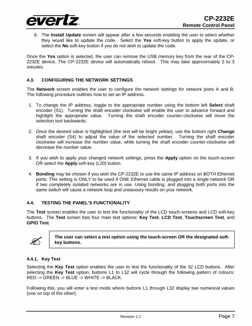
6. The Install Update screen will appear after a few seconds enabling the user to select whether they would like to update the code. Select the Yes soft-key button to apply the update, or select the No soft-key button if you do not wish to update the code.
Once the Yes option is selected, the user can remove the USB memory key from the rear of the CP-2232E device. The CP-2232E device will automatically reboot. This may take approximately 2 to 3 minutes.
4.3. CONFIGURING THE NETWORK SETTINGS
The Network screen enables the user to configure the network settings for network ports A and B. The following procedure outlines how to set an IP address.
1. To change the IP address, toggle to the appropriate number using the bottom left Select shaft
encoder (S1). Turning the shaft encoder clockwise will enable the user to advance forward and highlight the appropriate value. Turning the shaft encoder counter-clockwise will move the selection tool backwards.
2. Once the desired value is highlighted (the text will be bright yellow), use the bottom right Change
shaft encoder (S4) to adjust the value of the selected number. Turning the shaft encoder clockwise will increase the number value, while turning the shaft encoder counter-clockwise will decrease the number value.
3. If you wish to apply your changed network settings, press the Apply option on the touch-screen
OR select the Apply soft-key (L20) button. 4. Bonding may be chosen if you wish the CP-2232E to use the same IP address on BOTH Ethernet
ports. This setting is ONLY to be used if ONE Ethernet cable is plugged into a single network OR if two completely isolated networks are in use. Using bonding, and plugging both ports into the same switch will cause a network loop and unsavoury results on your network.
4.4. TESTING THE PANEL’S FUNCTIONALITY
The Test screen enables the user to test the functionality of the LCD touch-screens and LCD soft-key buttons. The Test screen lists four main test options: Key Test, LCD Test, Touchscreen Test, and GPIO Test.
The user can select a test option using the touch-screen OR the designated soft-key buttons.
4.4.1. Key Test
Selecting the Key Test option enables the user to test the functionality of the 32 LCD buttons. After selecting the Key Test option, buttons L1 to L32 will cycle through the following pattern of colours: RED -> GREEN -> BLUE -> WHITE -> BLACK. Following this, you will enter a test mode where buttons L1 through L32 display two numerical values (one on top of the other).
CP-2232E Remote Control Panel
Page 8 Revision 1.1
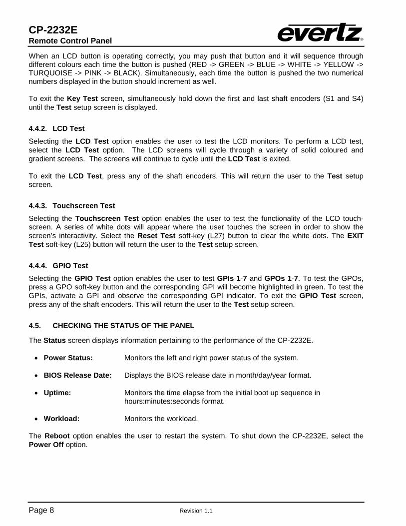
When an LCD button is operating correctly, you may push that button and it will sequence through different colours each time the button is pushed (RED -> GREEN -> BLUE -> WHITE -> YELLOW -> TURQUOISE -> PINK -> BLACK). Simultaneously, each time the button is pushed the two numerical numbers displayed in the button should increment as well. To exit the Key Test screen, simultaneously hold down the first and last shaft encoders (S1 and S4) until the Test setup screen is displayed.
4.4.2. LCD Test
Selecting the LCD Test option enables the user to test the LCD monitors. To perform a LCD test, select the LCD Test option. The LCD screens will cycle through a variety of solid coloured and gradient screens. The screens will continue to cycle until the LCD Test is exited. To exit the LCD Test, press any of the shaft encoders. This will return the user to the Test setup screen.
4.4.3. Touchscreen Test
Selecting the Touchscreen Test option enables the user to test the functionality of the LCD touch-screen. A series of white dots will appear where the user touches the screen in order to show the screen’s interactivity. Select the Reset Test soft-key (L27) button to clear the white dots. The EXIT Test soft-key (L25) button will return the user to the Test setup screen.
4.4.4. GPIO Test
Selecting the GPIO Test option enables the user to test GPIs 1-7 and GPOs 1-7. To test the GPOs, press a GPO soft-key button and the corresponding GPI will become highlighted in green. To test the GPIs, activate a GPI and observe the corresponding GPI indicator. To exit the GPIO Test screen, press any of the shaft encoders. This will return the user to the Test setup screen.
4.5. CHECKING THE STATUS OF THE PANEL
The Status screen displays information pertaining to the performance of the CP-2232E. • Power Status: Monitors the left and right power status of the system. • BIOS Release Date: Displays the BIOS release date in month/day/year format. • Uptime: Monitors the time elapse from the initial boot up sequence in
hours:minutes:seconds format. • Workload: Monitors the workload.
The Reboot option enables the user to restart the system. To shut down the CP-2232E, select the Power Off option.

CP-2232E Remote Control Panel
Revision 1.1 Page 9
5. SYSTEM CONFIGURATION
5.1. UPGRADING THE CP-2232E PANEL
5.1.1. Requirements 1. The user must have a laptop or PC connected to the same network as the CP-2232E. 2. The user must obtain upgrade files from Evertz Personnel.
a. Your computer must be running the Mozilla Firefox web browser located at:
http://www.mozilla.com/en-US/firefox/ b. This browser is also available in Chinese simplified and traditional, if preferred, by
clicking the “other languages…” option under the download link.
5.1.2. Getting Started 1. Set the IP address of the CP-2232E by holding down the first and last rotary encoders (S1 and
S4) on the far left of the panel for 6 seconds. c. Select the “Network” page. d. Set the IP address for the A port and ensure “bonding” is off (a red x should appear next
to it). e. Select Apply, then press the setup button.
2. Set the IP of your laptop or PC in the same range as the panel. 3. Ensure that Firefox is installed on your machine. If not, please review section 5.1.1 for
instructions on installing Firefox.
5.1.3. Upgrading Firmware on the CP-2232E 1. To upgrade firmware using the web interface, open a Firefox web browser and enter the IP
address of the CP-2232E, then press the <enter> key. The CP2232e web interface will appear, as shown in Figure 5-1.
Figure 5-1: CP2232e Web Interface
2. Select the Upgrade menu and the “Install Firmware” page will open as illustrated in Figure 5-2.

CP-2232E Remote Control Panel
Page 10 Revision 1.1
Figure 5-2: Install Firmware Page
3. Click on the Browse button to select the file to be updated (i.e. CP2232e-1.1_1.efp) and then
select the Install button to start the install. 4. If a reboot is required the panel should automatically reboot on its own otherwise you may
reboot it using the front panel. 5. Once the panel has rebooted you are ready to configure the CP-2232E.

CP-2232E Remote Control Panel
Revision 1.1 Page 11
5.2. SYSTEMS MENU
The Systems menu enables the user to upload product jar files, create services and templates, and add systems. Figure 5-3 illustrates the Systems drop down menu.
Figure 5-3: Systems Drop Down Menu
5.2.1. Products Page
The Products page, as illustrated in Figure 5-4, enables the user to upload product jar files to the control panel. Uploading the product files will provide access to the specific product parameters and enable configuration of such products. To open the Products page, select the Products option from the Systems drop down menu.
Figure 5-4: Products Page

CP-2232E Remote Control Panel
Page 12 Revision 1.1
The Products page has two control buttons, which are listed below:
• BROWSE: Selecting the Browse button will open a dialog box that enables the user to navigate to the desired jar file. Once the file is selected and opened, the filename will be displayed in the field to the left of the Browse button.
• UPLOAD: Selecting the Upload button will upload the selected file.
5.2.1.1. Products Uploaded
Products Type: This column lists the product files that are currently loaded on the control panel. If a product is loaded onto the panel, the product will be accessible in the Service Templates page (see section 5.2.2 for further information regarding the Service Templates page).
OID: This column identifies the product’s unique address known as an “Object Identification.” Version: This column lists the product’s current version number.
Select the button to delete the product.
5.2.2. Service Templates Page
The Service Templates page enables the user to create templates that contain SNMP parameters and controls for specific products. These templates are then used for creating and defining SNMP Services on the CP-2232E control panel. The Service Templates page also allows the user to edit existing templates.
Figure 5-5: Systems – Service Template Page

CP-2232E Remote Control Panel
Revision 1.1 Page 13
The user can add, copy, or remove a template using the Service Templates buttons listed in Table 5-1: Button Image Description
New Template
The New Template button enables the user to add and create a new template. Selecting this button will open a new template page as shown in Figure 5-9.
Duplicate Template
The Duplicate Template button enables the user to duplicate the selected template. Select the template that you wish to copy and then press the Duplicate Template button to create a replica of that template.
Delete Template
The Delete Template button enables the user to completely remove the currently selected template. Select the template that you wish to delete and then press the Delete Template button to remove the template.
Table 5-1: Service Template Buttons The templates that currently exist will be listed in the far left column as illustrated in Figure 5-6.
Figure 5-6: Service Template List
Once a template is selected or the user creates a new template, a new template page will appear enabling the user to add and/or edit parameters.

CP-2232E Remote Control Panel
Page 14 Revision 1.1
Figure 5-7: Customizing a Template
5.2.2.1. Service Template Controls
To modify the template, use the Service Templates controls as listed below:
• Name: To assign a name to the template, enter a unique name into the Name field. • Button Text: To assign button text to the template, enter a unique name into the Button Text
field. This is then used as a shortcut to the control when multiple templates are assigned to a SNMP Service.
• Product: The Product drop down menu provides a list of available products. Once the
desired product is selected, the parameter tree will reflect the available parameter items for the selected product. More products can be added to this list by uploading product jar files using the Products menu under the Systems menu.
• Bindings: This setting allows the user to enable or disable the Bindings option. Bindings are
used on controls that have can different parameters depending on the configuration of other controls. For example, if a specific card is set to use HD video the aspect controls would different than if the card was set to SD video.
• Add a Parameter: To add a parameter to the list, select the Add a Parameter button

CP-2232E Remote Control Panel
Revision 1.1 Page 15
• Delete Selected Parameters/Groups: Select the Delete Selected Parameters/Groups to delete a parameter/group.
• Add a Group: To add a group to the list, select the Add a Group button.
• Hide Tree View: Selecting the Hide Tree View button will hide the parameter tree view. Selecting this button again will show the parameter tree view.
• Show Details: Selecting the Show Details button will toggle the content of the Parameter field. When the user selects the Show Details button, the path of the parameter and the abbreviated name will be displayed in the Parameter field (i.e. VideoControl > Video Control > H Phase Offset (HPhaseOffset). If the user wishes to only display the Parameter name, then press the same button again (now identified as Hide Details).
• Save: Press the Save button to save all the changes you have made.
5.2.2.2. Service Template Parameter Tree
The Service Template Parameter Tree is used to select parameters and add them to the template. The user can navigate through the parameter tree by pressing the plus (+) and minus (-) buttons to expand or collapse the parameter items. Once the user has located their desired parameter, they can transfer it to the list by dragging the parameter from the tree and dropping it onto the list. To quickly locate a parameter, type the parameter name into the Search Parameter Tree… field and
press the <enter> key on your keyboard or select the icon. The search tool will expand the parameter tree to reveal the location of the parameter you entered.

CP-2232E Remote Control Panel
Page 16 Revision 1.1
Figure 5-8: Parameter Tree
5.2.2.3. Template Properties The user can adjust the template properties by entering the appropriate information into the fields below:
• #: Double-clicking a number in this column will highlight the corresponding parameter
in the Service Template Parameter Tree. • Parameter: This field identifies the parameter name and will display the location of the
parameter in the parameter tree when double-clicked. • Label: This field displays the name that is shown on the LCD screen for each control
parameter. The user can customize the buttons by entering a new label into this field.
• Default: This field displays the default level for the selected parameter. The user can enter
the appropriate unit into this field.

CP-2232E Remote Control Panel
Revision 1.1 Page 17
• Inc: Entering a number in this field will assign a number value that the encoder will increment when it is rotated. For example, if this value is set to 2, each time the shaft encoder is turned (clicked over once) the value will increment by 2 instead of a regular default unit of 1.
• Fine Inc: Entering a number in this field will assign a fine increment value that will be used when the shaft encoder is pushed. This value will then be used each time the shaft encoder is turned (clicked over once).
• Apply Type: This field enables the user to select an Apply Type. The user can select
“Pressed,” “Dynamic,” or “Cycle.”
• Filters: This field displays the range of values and control options available for the selected parameter. The user can change the minimum and maximum values and the parameter options using this field.
5.2.2.4. Creating a New Service Template To create a new template follow the procedure outlined below:
1. Navigate to the Service Templates control menu and click on the New Template button or select the Create a New One link. A new screen, as illustrated in Figure 5-9 will open.
Figure 5-9: New Template Page
2. Assign a new name to the template by entering a name into the Name field. 3. Assign a name for the designated LCD button using the Button Text field.
4. Select a product using the Product drop-down menu. Once the desired product is selected, the
parameter tree will reflect the available parameter items for the selected product. More products can be added to this list by uploading product jar files using the Products menu under the Systems menu.
5. Enable or disable Bindings using the Bindings drop-down menu. Please refer to section
5.2.2.1 for more information.
6. Drag and drop a card parameter from the parameter tree to the template parameter list in the middle of the screen. Please refer to Figure 5-10.

CP-2232E Remote Control Panel
Page 18 Revision 1.1
Figure 5-10: Assigning a Parameter
7. For each parameter that is added, the user can fill in the seven properties (i.e. Parameter,
Button Text, Default, Inc, etc). Please refer to section 5.2.2.3 for more information.
8. Click the SAVE button on the right hand side of the screen to save the template.
Please note that the user must press the “Save” button in order for changes to be saved and then select “Restart Panel Software” to apply the changes to the control panel.
5.2.2.5. Service Template Controls
To modify the template, use the Service Templates controls. Please refer to section 5.2.2.1 for more information.
5.2.3. Services Page
The Services page enables the user to create a service or edit an existing service, which can be loaded onto the CP-2232E control panel. Services are created by linking a Service Template to a particular Service and then defining the frame, card in a particular slot, and input using the Services page. The services that currently exist will be listed in the far left column as illustrated in Figure 5-11.
CP-2232E Remote Control Panel
Revision 1.1 Page 19
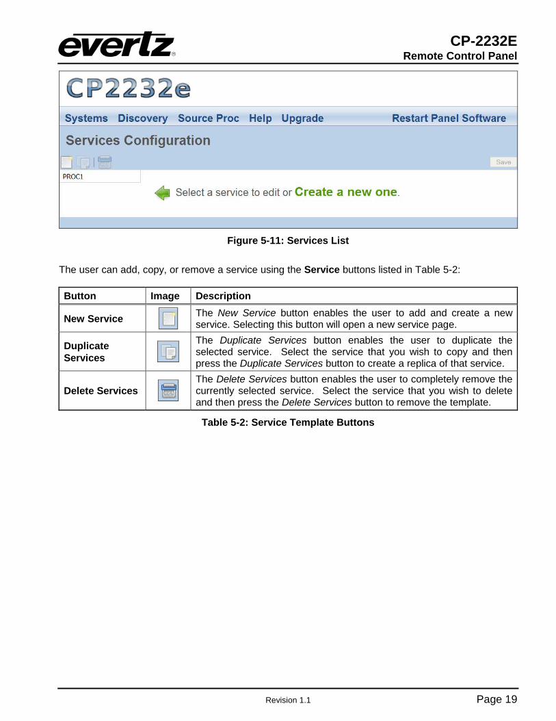
Figure 5-11: Services List
The user can add, copy, or remove a service using the Service buttons listed in Table 5-2: Button Image Description
New Service
The New Service button enables the user to add and create a new service. Selecting this button will open a new service page.
Duplicate Services
The Duplicate Services button enables the user to duplicate the selected service. Select the service that you wish to copy and then press the Duplicate Services button to create a replica of that service.
Delete Services
The Delete Services button enables the user to completely remove the currently selected service. Select the service that you wish to delete and then press the Delete Services button to remove the template.
Table 5-2: Service Template Buttons
CP-2232E Remote Control Panel
Page 20 Revision 1.1
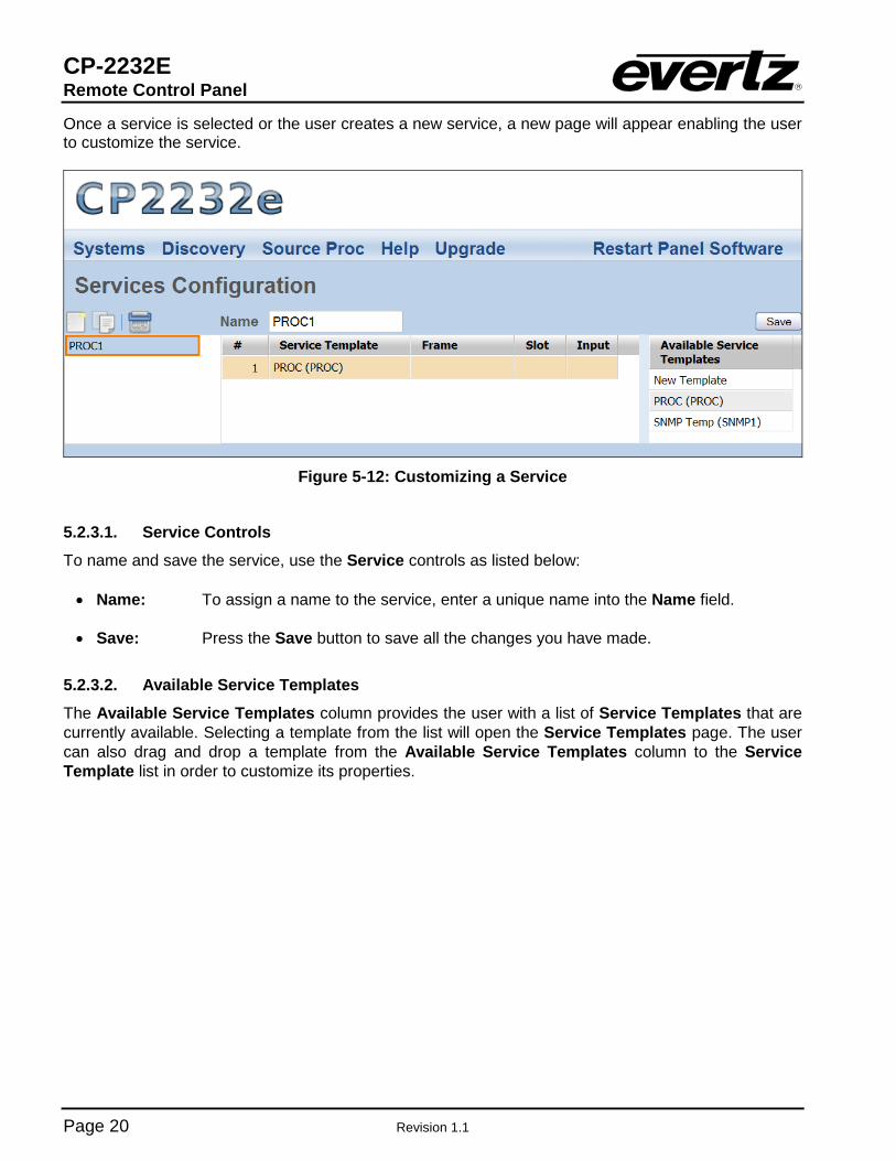
Once a service is selected or the user creates a new service, a new page will appear enabling the user to customize the service.
Figure 5-12: Customizing a Service
5.2.3.1. Service Controls
To name and save the service, use the Service controls as listed below:
• Name: To assign a name to the service, enter a unique name into the Name field. • Save: Press the Save button to save all the changes you have made.
5.2.3.2. Available Service Templates
The Available Service Templates column provides the user with a list of Service Templates that are currently available. Selecting a template from the list will open the Service Templates page. The user can also drag and drop a template from the Available Service Templates column to the Service Template list in order to customize its properties.

CP-2232E Remote Control Panel
Revision 1.1 Page 21
5.2.3.3. Service Properties The user can adjust the properties of the service by entering the appropriate information into the fields below:
• #: This field identifies the service template’s number in the list.
• Frame: This field enables the user to select the appropriate frame for the service.
• Slot: This field identifies the slot number of the card in the frame that will be controlled by the panel.
• Input: This field enables the user to assign an input number.
5.2.3.4. Add a Service Template to the Service List
1. Navigate to the Service option from the Systems menu. 2. Select the desired template from the Available Service Templates column and drag and drop
a template to the Service Template list.
3. Assign a “Frame,” “Slot,” and “Input” number to each service.
4. To apply these changes, select the Save button in the top right hand corner.
Please note that the user must press the “Save” button in order for changes to be saved and then select “Restart Panel Software” to apply the changes to the control panel.
5.2.4. Systems Page
The Systems page enables the user to view the devices that are currently available on the CP-2232E for connection and control as well as adding new devices. The user can also edit and/or change details, tags, and services for specific devices.
Figure 5-13: Systems Page

CP-2232E Remote Control Panel
Page 22 Revision 1.1
The user can add and/or remove a device using the Systems buttons listed in Table 5-3: Button Image Description
New Device
The New Device button enables the user to add and create a new device. Selecting this button will open a new system window as shown in Figure 5-14.
Delete Device
The Delete Device button enables the user to completely remove the currently selected device. Select the device that you wish to delete and then press the Delete Device button to remove the device.
Table 5-3: Service Template Buttons
Figure 5-14: New System Window
5.2.4.1. Device Properties The user can adjust each device’s properties by entering the appropriate information into the fields below:
If the user double clicks the System, Type, Details, and/or Tags field, an Update System window will open as illustrated in Figure 5-15.
System: This field displays the device’s name. If the user double clicks the System field, an
Update System window will open. Here, the user can edit the device’s name using the Name field.
Type: This field displays the device’s type. If the user double clicks the Type field, an Update
System window will open. Here, the user can select a device type using the Type drop down menu.

CP-2232E Remote Control Panel
Revision 1.1 Page 23
Details: This field displays specific details about the device. If the user double clicks the Details field, an Update System window will open. Here, the user can enter information about the device using the Details field.
Tags: This field displays the tags for a particular device. If the user double clicks the Tags
field, an Update System window will open. Here, the user can add tags to the device in order to create shortcut buttons while searching for a system on the first selection screen of the panel.
Service: This field displays the available SNMP services for the device. The user can drag and drop a service from the Available Services column to the desired device’s Service field.
Figure 5-15: Update System Window
5.3. DISCOVERY MENU
The Discovery menu, as illustrated in Figure 5-16, enables the user to set the appropriate discovery settings for the panel. The user can also configure the CP-2232E for communication with the VistaLINK® Alarm Server.

CP-2232E Remote Control Panel
Page 24 Revision 1.1
Figure 5-16: Discovery Menu
5.3.1. Settings Page
The Settings page enables the user to lock the Discovery system and set the refresh rate of the device.
Figure 5-17: Settings Page
Lock Discovery: This parameter allows the user to enable or disable the Lock Discovery. If set to
On, the Discovery system will not be permitted to add new hardware devices to the list of devices found. If set to Off, the Discovery system will be permitted to add new hardware devices to the list of devices found. Please note, when the Discovery system is set to On, hardware can be removed from the Systems page. It is recommended to leave the Lock Discovery setting to Off.
CP-2232E Remote Control Panel
Revision 1.1 Page 25
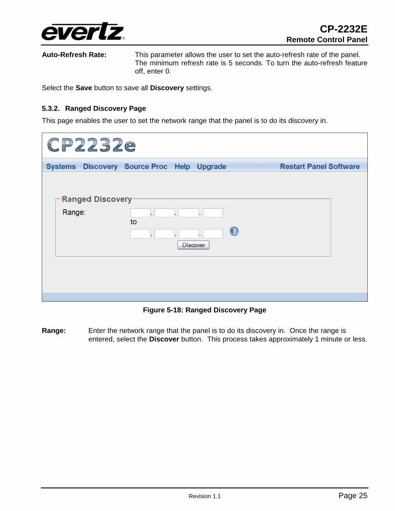
Auto-Refresh Rate: This parameter allows the user to set the auto-refresh rate of the panel. The minimum refresh rate is 5 seconds. To turn the auto-refresh feature off, enter 0.
Select the Save button to save all Discovery settings.
5.3.2. Ranged Discovery Page This page enables the user to set the network range that the panel is to do its discovery in.
Figure 5-18: Ranged Discovery Page
Range: Enter the network range that the panel is to do its discovery in. Once the range is
entered, select the Discover button. This process takes approximately 1 minute or less.
CP-2232E Remote Control Panel
Page 26 Revision 1.1
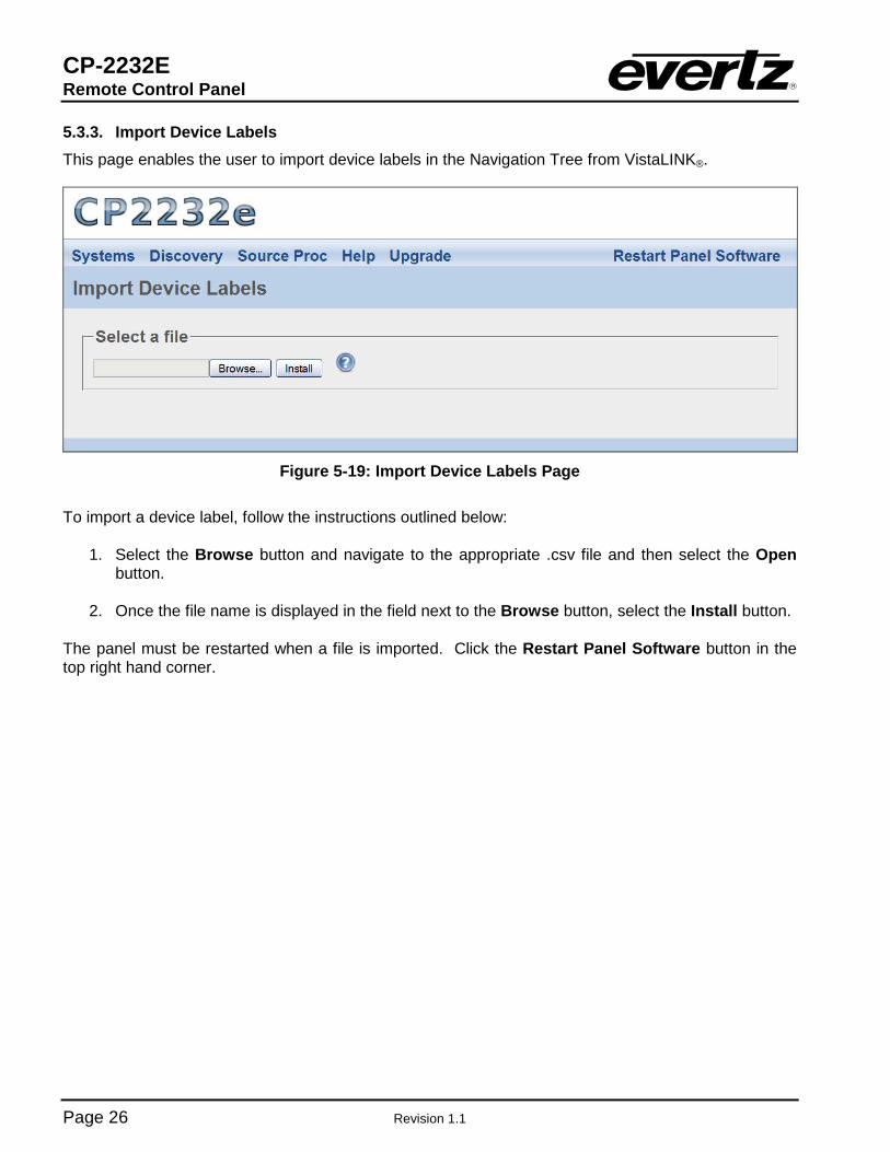
5.3.3. Import Device Labels This page enables the user to import device labels in the Navigation Tree from VistaLINK®.
Figure 5-19: Import Device Labels Page
To import a device label, follow the instructions outlined below:
1. Select the Browse button and navigate to the appropriate .csv file and then select the Open button.
2. Once the file name is displayed in the field next to the Browse button, select the Install button.
The panel must be restarted when a file is imported. Click the Restart Panel Software button in the top right hand corner.

CP-2232E Remote Control Panel
Revision 1.1 Page 27
5.3.4. VistaLINK® Alarm Server
This page enables the user to configure the VistaLINK® Alarm Server settings.
Figure 5-20: VistaLINK® Alarm Server
VistaLINK® Alarm Server: This field enables the user to enter the VistaLINK® Alarm Server
network address. Port: This field enables the user to enter the port number (the numerical input) to map to. Select the Save button to save all settings.
5.4. SOURCE PROC MENU
The Source Proc menu enables the user to create source-service, destination-service, and macro-service mapping.
Figure 5-21: Source Proc Menu

CP-2232E Remote Control Panel
Page 28 Revision 1.1
5.4.1. Source Proc Page
The Source Proc page enables the user to attach an SNMP service to a router’s input port.
Figure 5-22: Source Proc Page
1. The following items will be required before you begin:
a. The PRECISE “short name” from the EQX Server for the router containing the input or output you wish to map a service to.
b. The PRECISE port number (in other words, the numerical input) the service should be mapped to. This number should be entered without any preceding zeros. Enter the number one as: 1 not 001.
c. An Alias name for the router source (which will be used if the device name and port are not provided).
d. A Service created and saved on the CP-2232E panel.
2. Select the plus sign to create a new mapping. 3. Enter the PRECISE “short name” of the router device to map to in the Device Name field.
4. Enter the port number (the numerical input) to map to in the Port field.
5. Enter an Alias name for the router source. Please note that this parameter is optional. An
Alias will be used if a device name and port are not provided. The alias would be the Global name of the source as defined in the EQX Server.
6. Enter the name of the desired SNMP service in the Service Name field.
7. Once selected, click the Save button.
8. When you are finished mapping the SNMP Services, be sure to click the “Restart Panel
Software” link found at the top of each page.

CP-2232E Remote Control Panel
Revision 1.1 Page 29
5.4.2. Destination Proc Page
The Destination Proc page enables the user to attach an SNMP service to a router’s output port.
Figure 5-23: Destination Proc Page
To create a new Destination-Service Mapping, please follow the numbered instructions in section 5.4.1
5.4.3. Macros Page
The Macros page, as illustrated in Figure 5-24, enables the user to map a Macro to an SNMP Service. This will automatically fire the Macro on the VistaLINK® Alarm Server when the Service is loaded.
Figure 5-24: Macros Page
CP-2232E Remote Control Panel
Page 30 Revision 1.1
1. Select the plus sign to create a new Macro mapping. 2. Enter the name of the desired SNMP service in the Service Name field.
3. Enter the name of the Macro in the Macro Name field.
9. Once completed, select the Save.
4. When you are finished mapping the Macro, be sure to click the “Restart Panel Software” link
found at the top of each page.
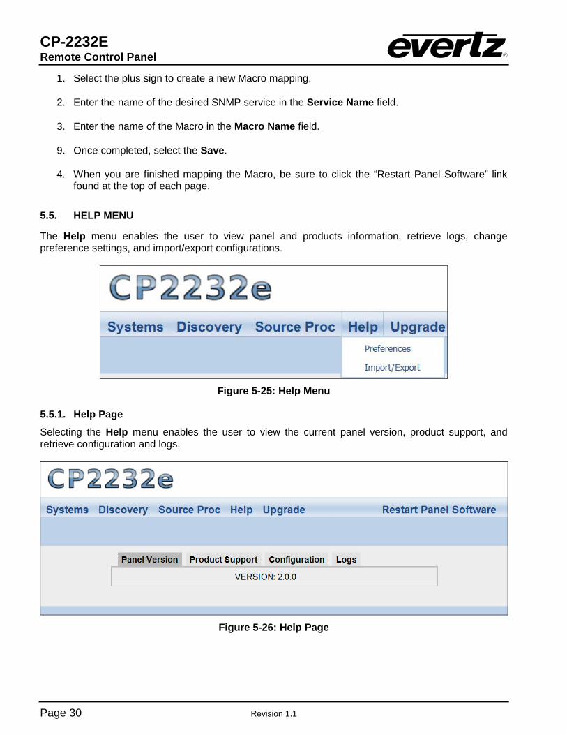
5.5. HELP MENU
The Help menu enables the user to view panel and products information, retrieve logs, change preference settings, and import/export configurations.
Figure 5-25: Help Menu
5.5.1. Help Page
Selecting the Help menu enables the user to view the current panel version, product support, and retrieve configuration and logs.
Figure 5-26: Help Page

CP-2232E Remote Control Panel
Revision 1.1 Page 31
5.5.1.1. Panel Version
Selecting the Panel Version option, as illustrated in Figure 5-26, will display the current panel’s version number.
5.5.1.2. Product Support
The Product Support option provides a list of current product versions.
Figure 5-27: Product Support Tab
Clicking the Product Versions text will reveal a list of currently supported products and their version numbers.
5.5.1.3. Configuration
The Configuration tab, as illustrated in Figure 5-28, enables the user to export the panel’s configuration settings.

CP-2232E Remote Control Panel
Page 32 Revision 1.1
Figure 5-28: Configuration Tab
Select the Export Configuration text and an Opening config.cf dialog box will be appear which will prompt the user to open or save the configuration file.
Figure 5-29: Opening config.cf Dialog Box
CP-2232E Remote Control Panel
Revision 1.1 Page 33
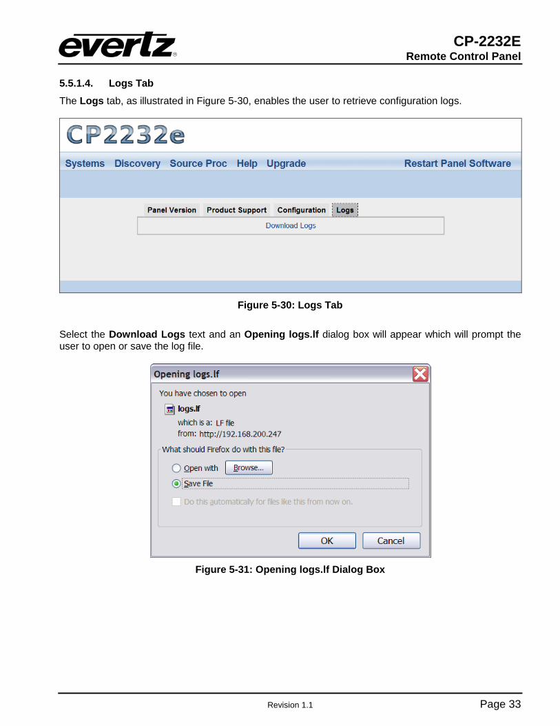
5.5.1.4. Logs Tab
The Logs tab, as illustrated in Figure 5-30, enables the user to retrieve configuration logs.
Figure 5-30: Logs Tab
Select the Download Logs text and an Opening logs.lf dialog box will appear which will prompt the user to open or save the log file.
Figure 5-31: Opening logs.lf Dialog Box

CP-2232E Remote Control Panel
Page 34 Revision 1.1
5.5.2. Preferences Page
The user can select the Preferences option from the Help menu drop down menu. The Preferences page enables the user to change the visual settings of the panel.
Figure 5-32: Preferences Page
5.5.2.1. Visual Settings
Theme: This parameter enables the user to the change the panel’s colour palette. Theme options include: “Dark Gray,” “Ocean Blue,” “Forest Green,” “Smokey Grey,” and “Classic.”
Auto-Select: This parameter enables the user to enable or disable the Auto-Select function. If set to
On, a single item in a list will be automatically selected (where applicable) without having to use the Select button. If set to No, the Select button will need to be used in order to select an item from a list.
Dial Rotation: This parameter enables the user to change the shaft encoders’ scrolling direction. The
“Clockwise scrolls to maximum” option will increase the number value when turning a shaft encoder clockwise. The “Clockwise scrolls to minimum” option will decrease the number value when turning a shaft encoder clockwise.
CP-2232E Remote Control Panel
Revision 1.1 Page 35
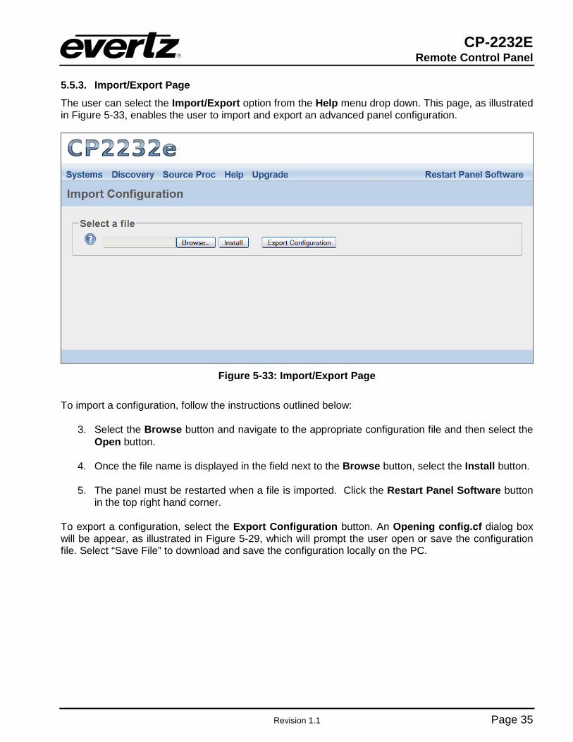
5.5.3. Import/Export Page
The user can select the Import/Export option from the Help menu drop down. This page, as illustrated in Figure 5-33, enables the user to import and export an advanced panel configuration.
Figure 5-33: Import/Export Page
To import a configuration, follow the instructions outlined below:
3. Select the Browse button and navigate to the appropriate configuration file and then select the Open button.
4. Once the file name is displayed in the field next to the Browse button, select the Install button.
5. The panel must be restarted when a file is imported. Click the Restart Panel Software button
in the top right hand corner. To export a configuration, select the Export Configuration button. An Opening config.cf dialog box will be appear, as illustrated in Figure 5-29, which will prompt the user open or save the configuration file. Select “Save File” to download and save the configuration locally on the PC.

CP-2232E Remote Control Panel
Page 36 Revision 1.1
5.6. UPGRADE MENU
The Upgrade menu enables the user to upgrade the firmware on the CP-2232E panel. Select the Upgrade menu and the Install Firmware page will open as illustrated in Figure 5-34.
Figure 5-34: Install Firmware Page
For instructions on how to upgrade the panel’s firmware, please refer to section 5.1.3.
CP-2232E Remote Control Panel
Revision 1.1 Page 37
6. ADDING AN EVERTZ SYSTEM TO CONTROL
6.1. CP-2232E CONTROL OF MVP SYSTEM
Controlling an MVP system from the CP-2232E panel requires a few “one time” steps (as well as a normal procedure) to be completed on the MVP system prior to working with the CP-2232E:
1. Set up the MVP system to allow control from the CP-2232E. (This step should only be performed once upon initial setup):
a. Ensure the MVP server is in operation. b. Confirm the “listen” port of the MVP server in the configuration (default is 9680) c. Create a canvas file for your MVP system and send it to the server. (If possible, please
provide the service with the number of display cards, displays, and resolutions that can be used to assist in building a custom canvas file)
i. Using the “Transfer scripts” button in the server, choose the remote file type of canvas. Select the browse button and navigate to your canvas.vssl file. Once selected, click the Transfer button. Restart the server to apply this canvas.
2. Daily operation of the MVP to allow the CP-2232E control of a layout:
a. Open an existing layout (while connected in maestro) and select the “save as script” option. Assign a descriptive name and then click send (you will need to do this with any layout you wish to appear on the CP-2232E).
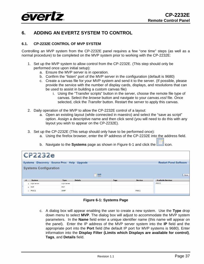
3. Set up the CP-2232E (This setup should only have to be performed once):
a. Using the firefox browser, enter the IP address of the CP-2232E into the address field.
b. Navigate to the Systems page as shown in Figure 6-1 and click the icon.
Figure 6-1: Systems Page
c. A dialog box will appear enabling the user to create a new system. Use the Type drop
down menu to select MVP. The dialog box will adjust to accommodate the MVP system parameters. In the Name field enter a unique identifier name (this name will appear on the panel). Enter the IP address of the MVP server system into the IP field and the appropriate port into the Port field (the default IP port for MVP systems is 9680). Enter information into the Display Filter (Limits which Displays are available for control), Tags, and Details field.

CP-2232E Remote Control Panel
Page 38 Revision 1.1
Figure 6-2: Create a MVP System
d. Once the user has filled out all the fields in the New System dialog box, select the Save
button. e. Then select the Save button in the top right of the Systems screen. f. The MVP system will be added to the list and a notification to restart the panel will
appear. In the very top right of every page is a link to “Restart Panel Software”. Select this link and the panel software will take approximately three seconds to restart.
g. When the panel restarts, the system should be displayed on the front panel of the CP-2232E.
4. Daily operation of the CP-2232e (Directly using the panel)
a. Select the MVP system from the CP2232E front panel by navigating to the appropriate system using the shaft encoders and soft-keys.
b. Once the list is generated, select a display from the list and select OK. c. The layout that is currently loaded will be displayed and a list of layouts that the user can
load will be provided. Select one of the layouts and then select the load button. d. The user can also change sources on the CP-2232E. This will allow you to pick a source
that is already located on the MVP somewhere else, without making routes. The user can select which audio to route to the monitor outputs. Furthermore, it will allow the user the ability to view thumbnails generated in real-time from the VIP/VIPX/VIPA/MVP attached to the system.
CP-2232E Remote Control Panel
Revision 1.1 Page 39
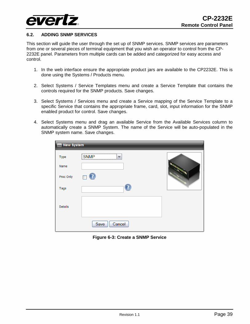
6.2. ADDING SNMP SERVICES
This section will guide the user through the set up of SNMP services. SNMP services are parameters from one or several pieces of terminal equipment that you wish an operator to control from the CP-2232E panel. Parameters from multiple cards can be added and categorized for easy access and control.
1. In the web interface ensure the appropriate product jars are available to the CP2232E. This is done using the Systems / Products menu.
2. Select Systems / Service Templates menu and create a Service Template that contains the
controls required for the SNMP products. Save changes.
3. Select Systems / Services menu and create a Service mapping of the Service Template to a specific Service that contains the appropriate frame, card, slot, input information for the SNMP enabled product for control. Save changes.
4. Select Systems menu and drag an available Service from the Available Services column to
automatically create a SNMP System. The name of the Service will be auto-populated in the SNMP system name. Save changes.
Figure 6-3: Create a SNMP Service

CP-2232E Remote Control Panel
Page 40 Revision 1.1
6.3. ADDING AN EQX SERVER
All router management of the CP-2232E for use in an EQX Server based system is done through the EQX Server WCT (web config tool). Please see the EQX Server manual for details on working with the CP-223E panel in that respect.
1. To add an EQX server, the user must open a Firefox browser and enter the IP address of the CP-2232E in the address field.
2. Navigate to the Systems page as shown in Figure 6-1 and click the icon.
3. A New System dialog box will appear enabling the user to create a new system. Use the Type drop down menu to select EQX Server. The dialog box will adjust to accommodate the EQX Server parameters. In the Name field enter a unique identifier name (this name will appear on the panel). Enter the IP address of the EQX server host into the IP field. Enter the appropriate port into the Port field. The default port is 8765. The user can also enter information into the Tags, and Details fields.
Figure 6-4: Add EQX Server
4. Once the user has filled out all the fields, select the Save button in the New System dialog box.
Once you return to the Systems page, click the Save button on the top right-hand side of the screen. In the very top right of the page is a link to “restart panel software”. Select this link and the panel software will take approximately three seconds to restart. When the panel restarts, the user can use the shaft encoders and soft-key buttons to toggle to the new EQX system configuration.

CP-2232E Remote Control Panel
Revision 1.1 Page 41
6.4. CREATING SOURCE-SERVICE MAPPING
Source-Service mapping is a unique and powerful tool in the EQX Server and CP-2232E system. The process is simple. Create SNMP services and then choose the routing device and source port to attach the service to. In this way, SNMP Services (and therefore Terminal gear parameters) can be accessed from within the EQX Server portion of the CP-2232E and users do not have to filter through long lists looking for the correct Service name. For more information on Mapping, please refer to section 5.4.

CP-2232E Remote Control Panel
Page 42 Revision 1.1
7. NAVIGATING THE CONTROL PANEL
Figure 7-1: Front Panel Display
The default router control view of the CP-2232E features two touch LCD screens with a maximum of four destinations per screen displaying the following information: Destination Name, Current Source Name, Next Source Name, Profile Selected Name, Destination Page, and State of the Destination (Lock/Protected/etc). The user can select a destination by touching the required destination within the quadrant. The shaft encoders can also be used to select a destination within a quadrant. The default button navigation pad will contain Src, Dst, Up, Dwn, Clear Next Src, Level, More, and Take buttons. Depending on the panel configuration the default button assignments may contain more or less then shown in Figure 7-1.
7.1. SOURCE (SRC) BUTTON
Figure 7-2: SRC Layout The SRC button when pushed will display a list of available sources in the Left display screen and the components that make up the source in the right screen (If the source contains video, audio, data, or other components). The shaft encoders under the Left or Right displays are used to navigate through the lists by turning the left shaft encoder under the respective screen. When the required source is highlighted, the Select button is used to confirm the choice and return the user to Eight Destination

CP-2232E Remote Control Panel
Revision 1.1 Page 43
view. The selected source will appear in the NXT source box in the destination that was previously selected; when the Take button is pressed the source will be routed. The Back button can be used to cancel the source search and return to the Eight Destination view.
Figure 7-3: SRC Keypad Display
The Alpha-Numeric button when pressed will allow the user to type the name of the required source in the Left screen. As the user types the CP-2232E will automatically filter the source list to display any source that matches the characters typed. If a character is typed incorrectly the DEL button can be used to delete the characters. The Left and Right buttons on the Left screen can be used to navigate the SRC Search box. When the required source is highlighted, the Enter button is used to confirm the choice and return the user to Eight Destination view. The selected source will appear in the NXT source box in the destination that was previously selected; when the Take button is pressed the source will be routed. The Back button can be used to cancel the source search and return to the Eight Destination view.

CP-2232E Remote Control Panel
Page 44 Revision 1.1
7.2. DESTINATION (DST) BUTTON
Figure 7-4: DST Layout The DST button when pushed will display a list of available destinations in the Left display screen and the information such as the Destination Physical Port Name/Number, the Current Source, and the Next Source in the Right display screen. The shaft encoders under the Left display are used to navigate through the destination list. When the required destination is highlighted, the Select button is used to confirm the choice and return the user to Eight Destination view. The selected destination will be automatically selected in the Eight Destination view. The quadrant view in the bottom of the Left display will show the user where the destination will appear when returning to the Eight Destination view. The Back button can be used to cancel the destination search and return to the Eight Destination view.
Figure 7-5: DST Keypad Display
The Alpha-Numeric button when pressed will allow the user to type the name of the required destination in the Left screen. As the user types the CP-2232E will automatically filter the destination list to display any destination that matches the characters typed. If a character is typed incorrectly the DEL button can be used to delete the characters. The Left and Right buttons on the Left screen can be used to navigate the DST Search box. When the required destination is highlighted, the Enter

CP-2232E Remote Control Panel
Revision 1.1 Page 45
button is used to confirm the choice and return the user to Eight Destination view. The selected destination will be automatically selected in the Eight Destination view. The quadrant view in the bottom of the Left display will show the user where the destination will appear when returning to the Eight Destination view. The Back button can be used to cancel the destination search and return to the Eight Destination view
7.3. UP & DOWN ARROWS
Figure 7-6: Up & Down Arrows Display
The Destination navigation buttons allow the user to scroll Up or Down through the pages of destinations. The Current Page and Total Number of Pages is displayed in the bottom right corner of each LCD screen. The last destination page contains “Dynamic Destinations”. The user can select a Dynamic Destination quadrant and assign a destination to it by using the destination button. The Dynamic Destination page allows the user to create custom destination pages with destinations arranged by the user.

CP-2232E Remote Control Panel
Page 46 Revision 1.1
7.4. CLEAR NEXT SOURCE BUTTON
Figure 7-7: Clear Next Source Button
The Clear Next SRC button allows the user to clear the pending or preset source for a selected destination.

CP-2232E Remote Control Panel
Revision 1.1 Page 47
7.5. LEVEL BUTTON
Figure 7-8: Level Button Display
The Level button when pushed will allow the user to enable or display specific levels for a destination. This could be an audio level or video level thereby allowing the user to accomplish a Breakaway route. The Left screen will display the selected destination for Breakaway, the Right screen will show the status of the levels for that destination. The Green X is displayed for an enabled level, if the Green X is not shown the level is disabled.
Figure 7-9: Selecting the Video Button
To enable or disable a level for a destination the user will push the associated level button on the panel. If a level has been disabled the associated level button will turn Red and the Right screen will not show the Green X for that level. The Left screen will display a breakaway icon for the destination. If a level has been enabled the associated level buttons will turn Green and the Right screen will show the Green X for that level. The Left screen will display a Green X icon for the destination is all levels are enabled. The level state will not change if the user selects the Back button to return to the Eight Destination view.

CP-2232E Remote Control Panel
Page 48 Revision 1.1
Figure 7-10: Select the ALL Button
The Select ALL or None button will toggle the level state of the levels for the selected destination. If levels have been disabled the associated level buttons will turn Red and the Right screen will not show the Green X for those levels. The Left screen will display a breakaway icon for the destination. If levels have been enabled the associated level buttons will turn Green and the Right screen will show the Green X for those levels. The Left screen will display a Green X icon for the destination if all levels are enabled. The level state will not change if the user selects the Back button to return to the Eight Destination view.
Figure 7-11: Selecting the BREAK AWAY Button
The Breakaway button when selected will each level individually on the LCD screen for the selected destination. The user can then select a specific level and route a source to that level by pressing the SRC button. The Up arrow will return the user to the Eight Destination view.

CP-2232E Remote Control Panel
Revision 1.1 Page 49
7.6. SELECTING THE “MORE” BUTTON
Figure 7-12: Selecting the “MORE” Button
The More button when selected will display the following button selections, Change Profile, Info, Tielines, Back, Toggle, Lock Destination, Protect Destination, One Destination View and Salvo. The Back button can be used to cancel the “More” function and return to the Eight Destination view.
Figure 7-13: Selecting the “CHNG PRFL” Button The CHG PRFL button when pressed will display a list of Profiles that have been assigned to the panel from MAGNUM. A Profile contains sources, destinations, labels, and categories. These can be different on a per profile basis. The Left and Right screens will display the list of available profiles for selection. The left shaft encoder under each screen can be used to scroll through the list. When the required Profile is highlighted, the Select button is used to confirm the choice and return the user to Eight Destination view with this profile loaded. The RFRSH PRFLS will re-query MAGNUM for any updates in the available profiles to the panel. The Back button can be used to cancel the profile selection and return to the Eight Destination view.
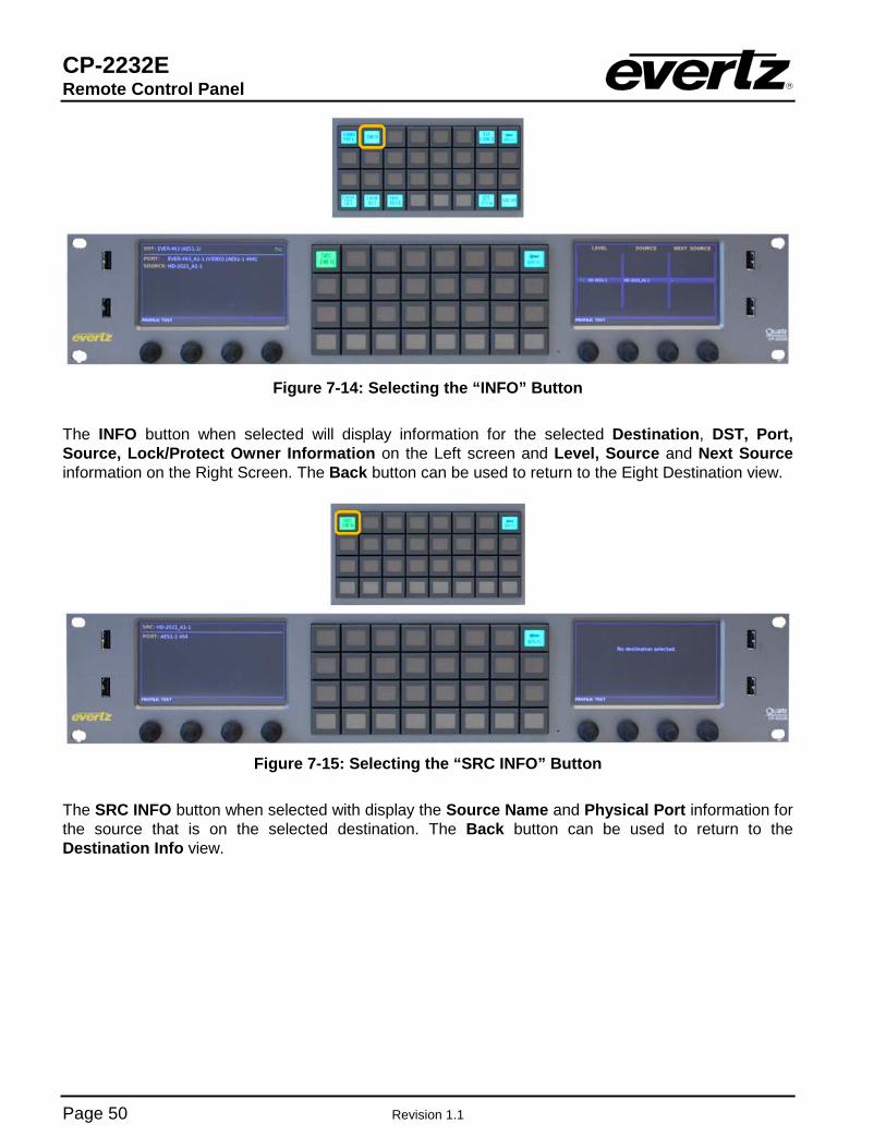
CP-2232E Remote Control Panel
Page 50 Revision 1.1
Figure 7-14: Selecting the “INFO” Button
The INFO button when selected will display information for the selected Destination, DST, Port, Source, Lock/Protect Owner Information on the Left screen and Level, Source and Next Source information on the Right Screen. The Back button can be used to return to the Eight Destination view.
Figure 7-15: Selecting the “SRC INFO” Button
The SRC INFO button when selected with display the Source Name and Physical Port information for the source that is on the selected destination. The Back button can be used to return to the Destination Info view.
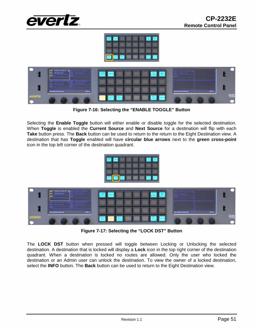
CP-2232E Remote Control Panel
Revision 1.1 Page 51
Figure 7-16: Selecting the “ENABLE TOGGLE” Button
Selecting the Enable Toggle button will either enable or disable toggle for the selected destination. When Toggle is enabled the Current Source and Next Source for a destination will flip with each Take button press. The Back button can be used to return to the return to the Eight Destination view. A destination that has Toggle enabled will have circular blue arrows next to the green cross-point icon in the top left corner of the destination quadrant.
Figure 7-17: Selecting the “LOCK DST” Button
The LOCK DST button when pressed will toggle between Locking or Unlocking the selected destination. A destination that is locked will display a Lock icon in the top right corner of the destination quadrant. When a destination is locked no routes are allowed. Only the user who locked the destination or an Admin user can unlock the destination. To view the owner of a locked destination, select the INFO button. The Back button can be used to return to the Eight Destination view.

CP-2232E Remote Control Panel
Page 52 Revision 1.1
Figure 7-18: Selecting the “PROTECT” Button
The PROTECT button when pressed will toggle between Protecting or Un-protecting the selected destination. A destination that is protected will display a Shield icon in the top right corner of the destination quadrant. A destination that is protected can only be routed on by the user who protected it. Only the user who protected the destination or an ‘Admin’ user can un-protect the destination. To view the owner of a protected destination, select the INFO button. The Back button can be used to return to the Eight Destination view.
Figure 7-19: Selecting the “TIELINES” Button
The TIELINES button when selected will display all Tielines configured for MAGNUM system in the Left screen and the Right screen will show the source on the selected Tieline and destinations that currently have the source. The left shaft encoder under each screen can be used to scroll through the list. The Back button can be used to return to the Eight Destination view.

CP-2232E Remote Control Panel
Revision 1.1 Page 53
Figure 7-20: Selecting the “ONE DST VIEW” Button
The ONE DST VIEW button when pushed will Toggle the CP-2232E between the Eight Destination View and One Destination View. When in One Destination View, the Left screen displays sources and the Right Screen shows one destination. The left shaft encoder under the Left display is used to navigate through the source lists by turning the left shaft encoder. When the required source is highlighted, the Take button is used the Take button is used to route the source. The Alpha-Numeric button when pressed will allow the user to type the name of the required source in the Left screen. As the user types the CP-2232E will automatically filter the source list to display any source that matches the characters typed. If a character is typed incorrectly the DEL button can be used to delete the characters. The Left and Right buttons on the Left screen can be used to navigate the SRC Search box. When the required source is highlighted, the Take button is used to route the source. The Back button can be used to cancel the source search and display all sources. The ONE DST VIEW right screen will display the Current Destination, the Current Source, and Previous Source (Toggle is automatically enabled in ONE DST VIEW).
Figure 7-21: Selecting the “TAKE” Button

CP-2232E Remote Control Panel
Page 54 Revision 1.1
The TAKE button whether in Eight Destination View or One Destination View when pressed will route the selected source to the selected destination. When a TAKE operation is available the TAKE button will appear PINK. If a TAKE failed because of an error, the button will appear RED, by selecting the MORE button and then VIEW ERROR the user can view details concerning the failure.
Figure 7-22: Selecting the “TOGGLE TAKE” Button
When in One Destination View the TOGGLE TAKE button can be used to toggle with each press between the Current Source and the Previous Source on the selected destination.
Figure 7-23: Selecting the “SALVO” Button
The SALVO button when pressed will display a list of Salvos in the left screen that are available to the current profile active on the panel. The left shaft encoder under the Left display is used to navigate through the Salvo list by turning the shaft encoder. When the required Salvo is highlighted, the RECAL SALVO button is fire the selected salvo. The Back button can be used to return to the Eight Destination view.