Embed Size (px)
Citation preview

ROHINI COLLEGE OF ENGINEERING AND TECHNOLOGY
DEPARTMENT OF ELECTRICAL AND ELECTRONICS ENGINEERING
COURSE MATERIAL
EE6009 - POWER ELECTRONICS FOR RENEWABLE ENERGY
SYSTEM IV YEAR – VIII SEMESTER
1

SYLLABUS
UNIT I INTRODUCTION 9
Environmental aspects of electric energy conversion: impacts of renewable energy generation on environment (cost-
GHG Emission) - Qualitative study of different renewable energy resources: Solar, wind, ocean, Biomass, Fuel cell,
Hydrogen energy systems and hybrid renewable energy systems.
UNIT II ELECTRICAL MACHINES FOR RENEWABLE ENERGY CONVERSION
Reference theory fundamentals-principle of operation and analysis: IG, PMSG, SCIG and DFIG.
9
UNIT III POWER CONVERTERS 9
Solar: Block diagram of solar photo voltaic system -Principle of operation: line commutated converters
(inversion-mode) - Boost and buck-boost converters- selection of inverter, battery sizing, array sizing
Wind: Three phase AC voltage controllers- AC-DC-AC converters: uncontrolled rectifiers, PWM Inverters,
Grid Interactive Inverters-matrix converters.
UNIT IV ANALYSIS OF WIND AND PV SYSTEMS
9
Stand alone operation of fixed and variable speed wind energy conversion systems and solar system- Grid connection Issues -Grid integrated PMSG, SCIG Based WECS, grid Integrated solar system
UNIT V HYBRID RENEWABLE ENERGY SYSTEMS 9
Need for Hybrid Systems- Range and type of Hybrid systems- Case studies of Wind-PV Maximum Power Point Tracking (MPPT).
TEXT BOOK:
1. S. N. Bhadra, D.Kastha, S.Banerjee, ―Wind Electrical Systems‖, Oxford University Press, 2005.
2. B.H.Khan Non-conventional Energy sources Tata McGraw-hill Publishing Company, New Delhi,2009.
REFERENCES:
1. Rashid .M. H ―power electronics Hand book‖, Academic press, 2001.
2. Ion Boldea, ―Variable speed generators‖, Taylor & Francis group, 2006.
3. Rai. G.D, ―Non conventional energy sources‖, Khanna publishes, 1993.
4. Gray, L. Johnson, ―Wind energy system‖, prentice hall linc, 1995.
5. Andrzej M. Trzynnadlowski, ‗Introduction to Modern Power Electronics‘, Second edition, wiley India Pvt. Ltd, 2012.
2
UNIT I
INTRODUCTION
SYLLABUS: Environmental aspects of electric energy conversion: impacts of renewable energy
generation on environment (Cost-GHG Emission) - Qualitative study of different renewable energy
resources: Solar,wind, ocean, Biomass, Fuel cell, Hydrogen energy systems and hybrid renewable
energy systems.
1. 1 ENVIRONMENTAL ASPECTS OF ELECTRIC ENERGY CONVERSION
1.1.1 Coal as thermal fuel
Coal is the raw fuel that provides 42% of the world‘s electricity. This distinguishes coal
as the world‘s primary energy source for electricity generation. The name coal refers to a family
of solid, organic fuels with different properties. Coal is mainly composed of elemental carbon
and is formed by the conversion of deposited organic material. The lowest grade of coal formed
is peat. Under the influence of high pressures and temperatures, the peat is transform into the
coal. Using coal to generate power or heat is an old technique. The heat energy of these fuels is
converted into mechanical energy by suitable prime movers such as steam engines, steam
turbines, internal combustion engines etc.
1.1.2 Coal mining
There are two types of coal mining, strip mining and underground long wall mining. The
environmental impacts from surface versus underground mining are not significantly different.
The main difference between these two mining techniques is that the surface mining subsystem
results in a higher amount of airborne ammonia emissions due to the production of ammonium
nitrate explosives which are used at the mine. Another important difference is that underground
mining requires limestone which emits a large amount of particulates during its production. The
problematic pollutants in emission of coal based generating plants are Sulfur dioxide (SO2),
Nitrogen oxides (NOx), carbon monoxide (CO) and carbon dioxide (CO2) and certain
hydrocarbons.
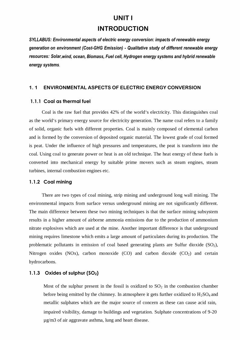
1.1.3 Oxides of sulphur (SO2)
Most of the sulphur present in the fossil is oxidized to SO2 in the combustion chamber
before being emitted by the chimney. In atmosphere it gets further oxidized to H2SO4 and
metallic sulphates which are the major source of concern as these can cause acid rain,
impaired visibility, damage to buildings and vegetation. Sulphate concentrations of 9-20
µg/m3 of air aggravate asthma, lung and heart disease.

1.1.4 Acidification
Acidification is one of the main problems arising from existing coal power. It takes place
during many steps in the life cycle of electricity produced by coal combustion. Pumped mine
water contains mud, dissolved sulphate and metal ions. It is also acidic and, therefore, needs to
be neutralizing before being discharged. Drainage water from refuse piles with excavated and
residual minerals can be very acidic, particularly if the rocks contain pyrite (ferric sulphide) that
undergoes oxidation processes when exposed to the atmosphere. These oxidation processes take
place in natural environments, but are greatly accelerated by mining activities, especia lly when
no alkaline rocks are present to neutralize the acid formed.
1.1.5 Impact on biodiversity
The main environmental effect of electricity produced by coal combustion is probably
related to the ubiquitous emission of greenhouse gases. The release t o the atmosphere of such
gases is larger from coal use than for any other fuel used for generating electricity. It is a general
contention that any additional increase of greenhouse gases in the atmosphere will exacerbate
global warming. This can lead to rapid changes in local weather conditions and can thus have
many and profound influences on biodiversity. Organisms that cannot adapt or migrate
successfully under changing climate conditions will be adversely affected.
1.2 ENVIRONMENT IMPACTS OF RENEWABLE ENERGY TECHNOLOGIES
Developing renewable energy technologies that exploit the sun, the wind, and geothermal
energy is critical to addressing concerns about climate change and some environmental issues.
However, using renewable energy sources will not eliminate all environmental concerns.
Although renewable energy sources produce relatively low levels of Green House Gas emissions
and conventional air pollution, manufacturing and transporting them will produce some
emissions and pollutants. The production of some photovoltaic (PV) cells, for instance,
generates toxic substances that may contaminate water resources. Renewable energy
installations can also disrupt land use and wildlife habitat, and some technologies consume
significant quantities of water.
To develop sound policies, policy makers must understand the relative environmental
impacts of alternative energy sources, including how the impacts of renewable energy
technologies compare to those of fossil-fuel technologies and to opportunities for improvements
in energy efficiency. Understanding the potential environmental impacts of renewable energy
technologies is also essential for identifying and pursuing designs, manufacturing methods,
project siting, utility operations, and so on to mitigate or offset these effects.

1.2.1 Life cycle uses of energy
For renewable energy sources, net energy ratio (NER) is expected to be greater than one,
indicating a positive return over the fossil-fuel energy investment. For fossil-fuel and nuclear
technologies, NERs are smaller than one and essentially represent the overall life cycle
efficiency of the project. NERs are strongly influenced by a number of underlying assumptions,
such as plant capacity and life expectancy. For electricity generation from wind and solar
energy, the strength of the resource (which will affect the capacity factor of the installed
technology) is also a critical assumption. For silicon PV specifically, the NER is highly
dependent upon the thickness of the wafer and the efficiency of the cell/module produced. NERs
would be significantly higher for waste biomass.
1.2.2 Local and regional air pollution
Most renewable energy technologies have much lower life cycle emissions of
conventional air pollutants than conventional coal and natural gas plants. One exception is
electricity generation from biomass, which can produce significant NOx, particulate matter, and
hazardous air pollutants, such as polycyclic aromatic hydrocarbons (PAHs). Although biomass
has lower nitrogen content than fossil fuels, a substantial quantity of NOx is formed whenever
high-temperature combustion occurs in air, through oxidation of atmospheric nitrogen (N2) at
high temperatures. Although direct emissions of NOx and SOx are expected to be low for
geothermal power plants, flash and dry-steam geothermal facilities can produce significant
quantities of hydrogen sulfide (H2S) from geothermal reservoirs, unless steps are taken to
decrease it.
1.2.3 Land and water use
The amount of land used is a rough substitute for other impacts of new development,
including impacts on ecosystems, cultural and historical resources, scenery, and agricultural
land. When the impacts on land use are measured simply by the surface area they occupy during
their life cycle, some renewable energy technologies appear to have heavy land-use
requirements. However, this approach does not take into account the intensity of land use or
whether the technology allows for simultaneous use of land for other purposes. Whereas coal-
fired power plants fully occupy the sites where they are constructed, small-scale PV installations
may be placed on rooftops where they cause little or no interference with the primary use of the
land for commercial or residential buildings. Thus, smaller scale or distributed solar
technologies may have less of an impact on land use and habitat loss than large-scale, central
station plants. Land-use concerns may also be addressed by deploying renewable energy systems
on previously developed sites, rather than in undeveloped areas.

Water is a scarce resource in large portions. Recent global circulation model projections
suggest that, if climate change proceeds as expected, under current business-as-usual scenarios,
freshwater supplies will become even scarcer in some parts of the world. Electricity production
using thermoelectric technologies requires vast amounts of water, primarily for cooling. In is
about 43 percent of existing thermoelectric generating capacity uses once-through cooling, 42
percent uses re-circulating wet towers, 14 percent uses re-circulating cooling ponds, and 1
percent uses dry cooling. Water use by power plants is characterized by withdrawals and
consumption. Although consumption is sometimes emphasized over withdrawals, the latter is
important, because power plant operation may be constrained by the amount of water available
for withdrawal and power plant uses may compete with other demands for water. Furthermore,
water returns can be significant sources of thermal pollution and may include discharges of
chemical pollutants, such as chlorine or other biocides used in cooling towers.
1.3 ENVIRONMENT IMPACTS OF DIFFERENT RENEWABLE ENERGY
SOURCES
All energy sources have some impact on our environment. Fossil fuels—coal, oil, and
natural gas—do substantially more harm than renewable energy sources by most measures,
including air and water pollution, damage to public health, wildlife and habitat loss, water use,
land use, and global warming emissions. However, renewable sources such as wind, solar,
geothermal, biomass, and hydropower also have environmental impacts, some of which are
significant. The exact type and intensity of environmental impacts varies depending on the
specific technology used, the geographic location, and a number of other factors. By
understanding the current and potential environmental issues associated with each renewable
energy source, we can takes steps to effectively avoid or minimize these impacts as they become
a larger portion of our electric supply.
1.3.1 Environmental impacts of wind energy
1.3.1.1 Land use
The land use impact of wind power facilities varies substantially depending on the site:
wind turbines placed in flat areas typically use more land than those located in hilly areas.
However, wind turbines do not occupy all of this land; they must be spaced approximately 5 to
10 rotor diameters apart (a rotor diameter is the diameter of the wind turbine blades). Thus, the
turbines themselves and the surrounding infrastructure (including roads and transmission lines)
occupy a small portion of the total area of a wind facility. Offshore wind facilities, require larger
amounts of space because the turbines and blades are bigger than their land-based counterparts.

1.3.1.2 Wildlife and habitat
The impact of wind turbines on wildlife, most notably on birds and bats, has been
widely document and studied. A recent survey founded evidence of bird and bat deaths from
collisions with wind turbines and due to changes in air pressure caused by the spinning turbines,
as well as from habitat disruption. Offshore wind turbines can have similar impacts on marine
birds, but as with onshore wind turbines, the bird deaths associated with offshore wind are
minimal. Wind farms located offshore will also impact fish and other marine wildlife.
1.3.1.3 Public health and community
Sound and visual impact are the two main public health and community concerns
associated with operating wind turbines. Most of the sound generated by wind turbines is
aerodynamic, caused by the movement of turbine blades through the air. There is also
mechanical sound generated by the turbine itself. Overall sound levels depend on turbine design
and wind speed. Some people living close to wind facilities have complained about sound and
vibration issues. Under certain lighting conditions, wind turbines can create an effect known as
shadow flicker. This annoyance can be minimized with careful siting, planting trees or installing
window sunshades, or curtailing wind turbine operations when certain lighting conditions exist.
1.3.1.4 Water use
There is no water impact associated with the operation of wind turbines. As in all
manufacturing processes, some water is used to manufacture steel and cement for wind turbines.
1.3.1.5 Life-cycle global warming emissions
While there are no global warming emissions associated with operating wind turbines,
there are emissions associated with other stages of a wind turbine‘s life-cycle, including
materials production, materials transportation, on-site construction and assembly, operation and
maintenance, and decommissioning and dismantlement. Estimates of total global warming
emissions depend on a number of factors, including wind speed, percent of time the wind is
blowing, and the material composition of the wind turbine.
1.3.2 Environmental impacts of solar energy systems
1.3.2.1 Land use
Depending on their location, larger utility-scale solar facilities can raise concerns about
land degradation and habitat loss. Total land area requirements vary depending on the
technology, the topography of the site, and the intensity of the solar resource. Estimates for
utility-scale PV systems range from 3.5 to 10 acres per megawatt, while estimates for

concentrated solar power (CSP) facilities are between 4 and 16.5 acres per megawatt. Smaller
scale solar PV arrays, which can be built on homes or commercial buildings, also have minimal
land use impact.
1.3.2.2 Water use
Solar PV cells do not use water for generating electricity. However, as in all
manufacturing processes, some water is used to manufacture solar PV components.
Concentrating solar thermal plants (CSP), like all thermal electric plants, require water for
cooling. Water use depends on the plant design, plant location, and the type of cooling system.
CSP plants that use wet-recirculation technology with cooling towers withdraw between 600 and
650 gallons of water per megawatt-hour of electricity produced. CSP plants with once-through
cooling technology have higher levels of water withdrawal, but lower total water consumption
(because water is not lost as steam). Dry-cooling technology can reduce water use at CSP plants
by approximately 90 percent. However, the exchanges to these water savings are higher costs
and lower efficiencies.
1.3.2.3 Hazardous materials
The PV cell manufacturing process includes a number of hazardous materials, most of
which are used to clean and purify the semiconductor surface. These chemicals, similar to those
used in the general semiconductor industry, include hydrochloric acid, sulfuric acid, nitric acid,
hydrogen fluoride, tri-chloroethane and acetone. The amount and type of chemicals used
depends on the type of cell, the amount of cleaning that is needed, and the size of silicon wafer.
Workers also face risks associated with inhaling silicon dust. Thus, PV manufactures must
follow the rules to ensure that workers are not harmed by exposure to these chemicals and that
manufacturing waste products are disposed of properly.
1.3.2.4 Life-cycle global warming emissions
While there are no global warming emissions associated with generating electricity from
solar energy, there are emissions associated with other stages of the solar life-cycle, including
manufacturing, materials transportation, installation, maintenance, and decommissioning and
dismantlement. Most estimates of life-cycle emissions for photovoltaic systems are between
0.07 and 0.18 pounds of carbon dioxide equivalent per kilowatt-hour.
1.3.3 Environmental impacts of geothermal energy systems
1.3.3.1 Water quality and use
Geothermal power plants can have impacts on both water quality and consumption. Hot
water pumped from underground reservoirs often contains high levels of sulfur, salt, and other
minerals. Most geothermal facilities have closed-loop water systems, in which extracted water is
pumped directly, back into the geothermal reservoir after it has been used for heat or electricity
production. In such systems, the water is contained within steel well casings cemented to the
surrounding rock. Water is also used by geothermal plants for cooling and re-injection.
Depending on the cooling technology used, geothermal plants can require between 1,700 and
4,000 gallons of water per megawatt-hour. However, most geothermal plants can use either
geothermal fluid or freshwater for cooling; the use of geothermal fluids rather than freshwater
clearly reduces the plants overall water impact.
1.3.3.2 Air emissions
The distinction between open- and closed-loop systems is important with respect to air
emissions. In closed-loop systems, gases removed from the well are not exposed to the
atmosphere and are injected back into the ground after giving up their heat, so air emissions are
minimal. In contrast, open-loop systems emit hydrogen sulfide, carbon dioxide, ammonia,
methane, and boron. Hydrogen sulfide, which has a distinctive ―rotten egg‖ smell, is the most
common emission. Once in the atmosphere, hydrogen sulfide changes into sulfur dioxide (SO2).
This contributes to the formation of small acidic particulates that can be absorbed by the
bloodstream and cause heart and lung disease. Sulfur dioxide also causes acid rain, which
damages crops, forests, and soils, and acidifies lakes and streams. However, SO2 emissions from
geothermal plants are approximately 30 times lower per megawatt-hour than from coal plants.
Some geothermal plants also produce small amounts of mercury emissions, which must
be mitigated using mercury filter technology. Scrubbers can reduce air emissions, but they
produce a watery sludge composed of the captured materials, including sulfur, vanadium, silica
compounds, chlorides, arsenic, mercury, nickel, and other heavy metals. This toxic sludge often
must be disposed of at hazardous waste sites.
1.3.3.3 Land use
The amount of land required by a geothermal plant varies depending on the properties of
the resource reservoir, the amount of power capacity, the type of energy conversion system, the
type of cooling system, the arrangement of wells and piping systems, and the substation and
auxiliary building needs. The Geysers, the largest geothermal plant in the world, has a capacity
of approximately 1,517 megawatts and the area of the plant is approximately 78 square
kilometers, which translates to approximately 13 acres per megawatt. Like the Geysers, many
geothermal sites are located in remote and sensitive ecological areas, so project developers must
take this into account in their planning processes.
1.3.3.4 Life-cycle global warming emissions
In open-loop geothermal systems, approximately 10 percent of the air emissions are
carbon dioxide and a smaller amount of emissions are methane, a more potent global warming
gas. Estimates of global warming emissions for open-loop systems are approximately 0.1
pounds of carbon dioxide equivalent per kilowatt-hour. In closed-loop systems, these gases are
not released into the atmosphere, but there are a still some emissions associated with plant
construction and surrounding infrastructure. Enhanced geothermal systems, which require
energy to drill and pump water into hot rock reservoirs, have life-cycle global warming emission
of approximately 0.2 pounds of carbon dioxide equivalent per kilowatt -hour. To put this into
context, estimates of life-cycle global warming emissions for natural gas generated electricity
are between 0.6 and 2 pounds of carbon dioxide equivalent per kilowatt-hour and estimates for
coal-generated electricity are 1.4 and 3.6 pounds of carbon dioxide equivalent per kilowatt-
hour.
1.3.4 Environmental impacts of hydroelectric energy systems
1.3.4.1 Land use
The size of the reservoir created by a hydroelectric project can vary widely, depending
largely on the size of the hydroelectric generators and the topography of the land. Hydroe lectric
plants in flat areas tend to require much more land than those in hilly areas or canyons where
deeper reservoirs can hold more volume of water in a smaller space. Flooding land for a
hydroelectric reservoir has an extreme environmental impact: it destroys forest, wildlife habitat,
agricultural land, and scenic lands.
1.3.4.2 Wildlife impacts
Dammed reservoirs are used for multiple purposes, such as agricultural irrigation, flood
control, and recreation, so not all wildlife impacts associated with dams can be directly
attributed to hydroelectric power. However, hydroelectric facilities can still have a major impact
on aquatic ecosystems. For example, though there are a variety of methods to minimize the
impact including fish ladders and in-take screens), fish and other organisms can be injured and
killed by turbine blades. Apart from direct contact, there can also be wildlife impacts both within
the dammed reservoirs and downstream from the facility. Reservoir water is usually more
stagnant than normal river water. As a result, the reservoir will have higher than normal amounts
of sediments and nutrients, which can cultivate an excess of algae and other aquatic weeds.
These weeds can crowd out other river animal and plant-life, and they must be controlled
through manual harvesting or by introducing fish that eat these plants. In addition, water is lost
through evaporation in dammed reservoirs at a much higher rate than in flowing rivers.

1.3.4.3 Life-cycle global warming emissions
Global warming emissions are produced during the installation and dismantling of
hydroelectric power plants, but recent research suggests that emissions during a facility‘s
operation can also be significant. Such emissions vary greatly depending on the size of the
reservoir and the nature of the land that was flooded by the reservoir. Small run-of-the-river
plants emit between 0.01 and 0.03 pounds of carbon dioxide equivalent per kilowatt -hour. Life-
cycle emissions from large-scale hydroelectric plants built in semi-arid regions are also modest:
approximately 0.06 pounds of carbon dioxide equivalent per kilowatt -hour. However, estimates
for life-cycle global warming emissions from hydroelectric plants built in tropical areas are
much higher. After the area is flooded, the vegetation and soil in these areas decomposes and
releases both carbon dioxide and methane. The exact amount of emissions depends greatly on
site-specific characteristics. However, current estimates suggest that life-cycle emissions can be
over 0.5 pounds of carbon dioxide equivalent per kilowatt-hour.
1.3.5 Environmental IMPACTS of Biomass energy systems
1.3.5.1 Deforestation and land degradation
Biomass comprising traditional fuels constitutes about 50% of energy consumption in
developing countries. Deforestation leading to soil erosion, risks of floods, desertification on
account of clearing of forests and woodlands for agriculture and livestock, and so on, are the
common concerns of environmentalists at macro levels. At a micro level, the concerns range
from non-suitability of forest soils for agricultural purposes, health problems due to smoke
caused by burning of fuel-wood, loss in soil fertility due to use of agricultural residues and so
on. Even a shift towards non-wood biomass fuels creates direct competition with animals that
rely upon crop remains and the plants for food. Imbalance between the demand and production
of fuel-wood is reported to be one of the primary factors responsible for forest depletion. The
increasing use of fuel-wood for meeting the domestic and industrial needs of both rural and
urban areas has contributed to forest decline. The environmental impacts of urban fuel-wood
consumption have been severe due to commercial exploitation of fuel-wood for charcoal
production. The demand for charcoal in urban areas has spread deforestation, which begins at
the surrounding areas of urban centres and moving outwards.
1.3.5.2 Loss of soil nutrients
Agricultural residues constitute an important source of energy in rural areas of
developing countries when left on fields improves the fertility of the soil. The use of agricultural
residues for energy would thus be an issue if it reduces the fertility of the soil. It is important to
note that all residues do not have the same effect on the soil. Some residues such as corncobs,
rice husk, jute sticks, cotton stock, coffee pruning, and coconut shells do not decompose easily

and have potential as energy sources. The choice of agricultural residues thus has an impact on
the environment. Cattle dung, similarly, though it is a fertilizer, loses its value as fertilizer if
burnt or left under the sun for a few days. The two categories of residues from agriculture sector
are crop residue and cattle dung. Currently crop residue of cereals is largely used as foo d and
woody residues are used as fuel. Burning of woody crop residue may not lead to any significant
loss of nutrients to soil. Burning of cattle dung as fuel leads to loss of organic matter and other
nutrients affecting crop production.
1.3.6 Environmental impacts of tidal energy systems
1.3.6.1 Understanding environmental impacts
In spite of the many benefits of exploiting tidal power, there are negative impacts, as
well. For example, the risk to the marine environment and marine mammals is largely unknown.
In order to operate tidal power stations appropriately and analyze the potential contribution tidal
power can make in terms of renewable energy, we must better understand the environmental
impacts of this technology. One important mention is the difference between environmental
effects and environmental impacts. On one hand, environmental effects refer to the wide range
of potential interactions between tidal energy equipment and the marine ecosystems. On the
other hand, environmental impacts are those particular effects that we know for sure will cause
deleterious ecological alterations.
1.3.6.2 Environmental impacts of Tidal energy
In many ways, the environmental impacts of harnessing tidal power are similar to those
of offshore wind power generation. Several assessments over the past few years have identified
the following potential environmental impacts. These indirect ecological impacts would result
from lengthy installation of offshore renewable energy projects.
Changing of substrates, sediment transit and deposition;
Alteration of waves and sea currents;
Noise pollution during installation and operation;
Alteration of ecosystems for regional organisms;
Emission of harmful electromagnetic fields;
Intrusion upon animal migrations; and
Potential strikes by any moving parts of the tidal system.
1.3.7 Environmental impacts of Hydrogen-based energy systems
There is increasing interest in the role that hydrogen-based energy systems may play in
the future, especially in the transport sector. They appear to be an attractive alternative to current
fossil fuel-based energy systems in the future, since these have been proven to affect climate due

to greenhouse gasses emissions. However, any future hydrogen-based economy would need to
assess the possible global environmental impacts of such alternative energy production.
Emissions of hydrogen lead to increased burdens of methane and ozone and hence to an increase
in global warming. Therefore, hydrogen can be considered as an indirect greenhouse gas with
the potential to increase global warming. The scientists have estimated that the potential effects
on climate from hydrogen-based energy systems would be much lower than those from fossil
fuel-based energy systems. However, such impacts will depend on the rate of hydrogen leakage
during its synthesis, storage and use. The researchers have calculated that a global hydrogen
economy with a leakage rate of 1% of the produced hydrogen would produce a climate impact
of 0.6% of the fossil fuel system it replaces. If the leakage rate was 10%, then the climate impact
would be 6% of that of the fossil fuel system.
1.3.8 Environmental Impacts of Hydrokinetic Energy systems
Hydrokinetic energy, which includes wave and tidal power, encompasses an array of
energy technologies, many of which are still in the experimental stages or in the early stages of
deployment. While actual impacts of large-scale operations have not been observed, a range of
potential impacts can be projected. For example, wave energy installations can require large
expanses of ocean space, which could compete with other uses—such as fishing and shipping—
and cause damage to marine life and habitats. Some tidal energy technologies are located at the
mouths of ecologically-sensitive estuary systems, which could cause changes in hydrology and
salinity that negatively impact animal and plant life.
1.3.9 Greenhouse gas emissions (GHG)
Compared to fossil-fuel-based electricity generation, renewable energy technologies
offer a major advantage in lower emissions of CO2 and other GHGs. In addition, all forms of
renewable electricity production are expected to have significantly lower life cycle GHG
emissions than electricity production from conventional coal and natural gas plants. Renewable
energy would have less of an advantage if carbon capture and sequestration were included with
fossil-fuel power plants, or if energy storage systems, such as battery energy storage,
compressed air energy storage, or pumped hydro storage, were included as part of renewable
energy systems. GHG emissions for some renewable technologies are difficult to estimate. For
example, emissions from bio-power vary, depending on which feedstock is used and the
assumptions about their production. Most CO2 emission (CO2e) values for bio-power range from
15 to 52 g CO2e/kWh for biomass derived from cultivated feed-stocks, excluding emissions
associated with initial land conversion. If carbon capture and storage were added to bio -power
systems, there would also be large reductions in CO2e values.

1.4. QUALITATIVE STUDY OF DIFFERENT RENEWABLE ENERGY
RESOURCES
1.4.1 Solar energy
1.4.1.1 Concentrating solar power (CSP) technologies
Concentrating Solar Power (CSP) technologies use mirrors to concentrate (focus) the
sun's light energy and convert it into heat to create steam to drive a turbine that generates
electrical power. CSP technology utilizes focused sunlight. CSP plants generate electric power
by using mirrors to concentrate (focus) the sun's energy and convert it into high-temperature
heat. That heat is then channeled through a conventional generator. The plants consist of two
parts: one that collects solar energy and converts it to heat, and another that converts the heat
energy to electricity.
1.4.1.2 Solar photovoltaic technology basics
Solar cells, also called photovoltaic (PV) cells by scientists, convert sunlight directly
into electricity. PV gets its name from the process of converting light (photons) to electricity
(voltage), which is called the PV effect. Traditional solar cells are made from silico n, are usually
flat-plate, and generally are the most efficient. Second-generation solar cells are called thin-film
solar cells because they are made from amorphous silicon or non-silicon materials such as
cadmium telluride. Thin film solar cells use layers of semiconductor materials only a few
micrometers thick. Because of their flexibility, thin film solar cells can double as rooftop
shingles and tiles, building facades, or the glazing for skylights. Third-generation solar cells are
being made from a variety of new materials besides silicon, including solar inks using
conventional printing press technologies, solar dyes, and conductive plastics. Some new solar
cells use plastic lenses or mirrors to concentrate sunlight onto a very small piece of high
efficiency PV material. The PV material is more expensive, but because so little is needed, these
systems are becoming cost effective for use by utilities and industry.
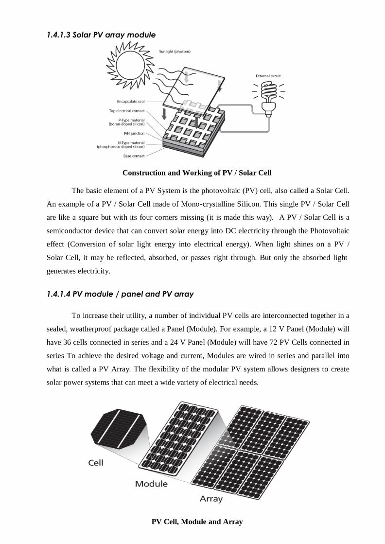
1.4.1.3 Solar PV array module
Construction and Working of PV / Solar Cell
The basic element of a PV System is the photovoltaic (PV) cell, also called a Solar Cell.
An example of a PV / Solar Cell made of Mono-crystalline Silicon. This single PV / Solar Cell
are like a square but with its four corners missing (it is made this way). A PV / Solar Cell is a
semiconductor device that can convert solar energy into DC electricity through the Photovoltaic
effect (Conversion of solar light energy into electrical energy). When light shines on a PV /
Solar Cell, it may be reflected, absorbed, or passes right through. But only the absorbed light
generates electricity.
1.4.1.4 PV module / panel and PV array
To increase their utility, a number of individual PV cells are interconnected together in a
sealed, weatherproof package called a Panel (Module). For example, a 12 V Panel (Module) will
have 36 cells connected in series and a 24 V Panel (Module) will have 72 PV Cells connected in
series To achieve the desired voltage and current, Modules are wired in series and parallel into
what is called a PV Array. The flexibility of the modular PV system allows designers to create
solar power systems that can meet a wide variety of electrical needs.
PV Cell, Module and Array
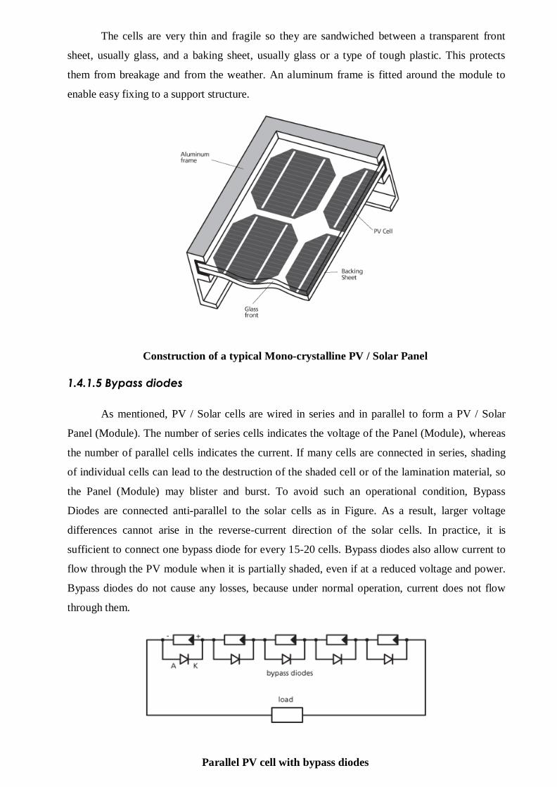
The cells are very thin and fragile so they are sandwiched between a transparent front
sheet, usually glass, and a baking sheet, usually glass or a type of tough plastic. This protects
them from breakage and from the weather. An aluminum frame is fitted around the module to
enable easy fixing to a support structure.
Construction of a typical Mono-crystalline PV / Solar Panel
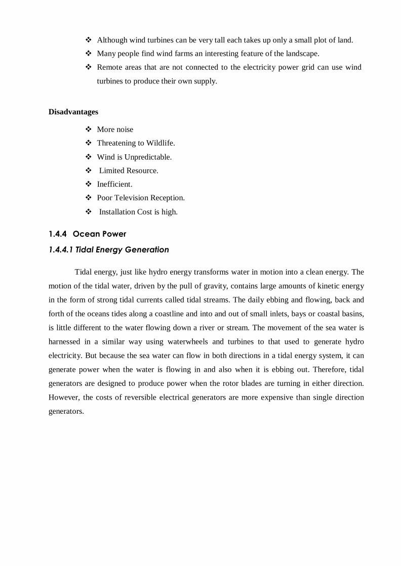
1.4.1.5 Bypass diodes
As mentioned, PV / Solar cells are wired in series and in parallel to form a PV / Solar
Panel (Module). The number of series cells indicates the voltage of the Panel (Module), whereas
the number of parallel cells indicates the current. If many cells are connected in series, shading
of individual cells can lead to the destruction of the shaded cell or of the lamination material, so
the Panel (Module) may blister and burst. To avoid such an operational condition, Bypass
Diodes are connected anti-parallel to the solar cells as in Figure. As a result, larger voltage
differences cannot arise in the reverse-current direction of the solar cells. In practice, it is
sufficient to connect one bypass diode for every 15-20 cells. Bypass diodes also allow current to
flow through the PV module when it is partially shaded, even if at a reduced voltage and power.
Bypass diodes do not cause any losses, because under normal operation, current does not flow
through them.
Parallel PV cell with bypass diodes

1.4.1.6 Photovoltaic Power Systems
Photovoltaic (PV) technology converts one form of energy (sunlight) into another form
of energy (electricity) using no moving parts, consuming no conventional fossil fuels, creating
no pollution, and lasting for decades with very little maintenance. The use of a widely available
and reasonably reliable fuel source—the sun—with no associated storage or transportation
difficulties and no emissions makes this technology eminently practicable for powering remote
scientific research platforms. The completely profitable nature of the technology also lends itself
well to varying power requirements–from the smallest autonomous research platforms to
infrastructure-based systems. Based on semiconductor technology, solar cells operate on the
principle that electricity will flow between two semiconductors when they are put into contact
with each other and exposed to light (photons). This phenomenon is known as the photovoltaic
effect.
1.4.2 Wind energy
Wind energy is energy from moving air, caused by temperature (and therefore pressure)
differences in the atmosphere. Irradiance from the sun heats up the air, forcing the air to rise.
Conversely, where temperatures fall, a low pressure zone develops. Winds (i.e. air flows)
balance out the differences. Hence, wind energy is solar energy converted into kinetic energy of
moving air.
1.4.2.1 Characteristics
As the wind power is proportional to the cubic wind speed, it is crucial to have detailed
knowledge of the site-specific wind characteristics. Even small errors in estimation of wind
speed can have large effects on the energy yield, but also lead to poor choices for turbine and
site. An average wind speed is not sufficient. Site-specific wind characteristics related to wind
turbines include:
Mean wind speed: Only interesting as a headline figure, but does not tell how often high
wind speeds occur.
Wind speed distribution : diurnal, seasonal, annual patterns
Turbulence: short-term fluctuations
Long-Term Fluctuations
Distribution Of Wind Direction
Wind Shear (Profile)

1.4.2.2 Wind turbine types
Horizontal Axis Wind Turbines (HAWT)
Horizontal axis wind turbines, also shortened to HAWT, are the common style that most
of us think of when we think of a wind turbine. A HAWT has a similar design to a windmill; it
has blades that look like a propeller that spin on the horizontal axis. Horizontal axis wind
turbines have the main rotor shaft and electrical generator at the top of a tower, and they must be
pointed into the wind. Small turbines are pointed by a simple wind vane placed square with the
rotor (blades), while large turbines generally use a wind sensor coupled with a servo motor to
turn the turbine into the wind. Most large wind turbines have a gearbox, which turns the slow
rotation of the rotor into a faster rotation that is more suitable to drive an electrical generator.
Horizontal Axis Wind Turbine
Since a tower produces turbulence behind it, the turbine is usually pointed upwind of the
tower. Wind turbine blades are made stiff to prevent the blades from being pushed into the tower
by high winds. Additionally, the blades are placed a considerable distance in front of the tower
and are sometimes tilted up a small amount.
Advantages
The tall tower base allows access to stronger wind in sites with wind shear.
High efficiency since the blades always moves perpendicularly to the wind,
receiving power through the whole rotation.
In contrast, all vertical axis wind turbines, and most proposed airborne wind
turbine designs, involve various types of reciprocating actions, requiring airfoil
surfaces to backtrack against the wind for part of the cycle.
Backtracking against the wind leads to inherently lower efficiency.

Disadvantages
Massive tower construction is required to support the heavy blades, gearbox, and
generator.
Components of a horizontal axis wind turbine (gearbox, rotor shaft and brake
assembly) being lifted into position.
Their height makes them obtrusively visible across large areas, disrupting the
appearance of the landscape and sometimes creating local opposition.
HAWTs require an additional yaw control mechanism to turn the blades toward
the wind.
Vertical Axis Wind Turbines (VAWT)
Vertical axis wind turbines, as shortened to VAWTs, have the main rotor shaft arranged
vertically. The main advantage of this arrangement is that the wind turbine does not need to be
pointed into the wind. This is an advantage on sites where the wind direction is highly variable
or has turbulent winds. With a vertical axis, the generator and other primary components can be
placed near the ground, so the tower does not need to support it, also makes maintenance easier.
The main drawback of a VAWT generally creates drag when rotating into the wind.
Vertical Axis Wind Turbine
It is difficult to mount vertical-axis turbines on towers, meaning they are often installed
nearer to the base on which they rest, such as the ground or a building rooftop. The wind speed
is slower at a lower altitude, so less wind energy is available for a g iven size turbine. Air flow
near the ground and other objects can create turbulent flow, which can introduce issues of
vibration, including noise and bearing wear which may increase the maintenance or shorten its
service life. However, when a turbine is mounted on a rooftop, the building generally redirects
wind over the roof and these can double the wind speed at the turbine. If the height of the
rooftop mounted turbine tower is approximately 50% of the building height, this is near the
optimum for maximum wind energy and minimum wind turbulence.

Advantages
No yaw mechanisms are needed.
A VAWT can be located nearer the ground, making it easier to maintain the
moving parts.
VAWTs have lower wind startup speeds than the typical the HAWTs.
VAWTs may be built at locations where taller structures are prohibited.
VAWTs situated close to the ground can take advantage of locations where
rooftops, mesas, hilltops, ridgelines, and passes funnel the wind and increase
wind velocity.
Disadvantages
Most VAWTs have an average decreased efficiency from a common HAWT,
mainly because of the additional drag that they have as their blades rotate into the
wind.
Versions that reduce drag produce more energy, especially those that funnel wind
into the collector area.
Having rotors located close to the ground where wind speeds are lower and do
not take advantage of higher wind speeds above.
1.4.3 Component of a wind turbine
1.4.3.1 Rotor
The part of the wind turbine that collects energy from the wind is called the rotor. The
rotor usually consists of two or more wooden, fiberglass or metal blades which rotate about an
axis (horizontal or vertical) at a rate determined by the wind speed and the shape of the blades.
The blades are attached to the hub, which in turn is attached to the main shaft.
1.4.3.2 Drag Design
Blade designs operate on either the principle of drag or lift. For the drag design, the
wind literally pushes the blades out of the way. Drag powered wind turbines are characterized
by slower rotational speeds and high torque capabilities. They are useful for the pumping,
sawing or grinding work. For example, a farm-type windmill must develop high torque at start-
up in order to pump, or lift, water from a deep well.

1.4.3.3 Lift Design
The lift blade design employs the same principle that enables airplanes, kites and birds
to fly. The blade is essentially an airfoil, or wing. When air flows past the blade, a wind speed
and pressure differential is created between the upper and lower blade surfaces. The pressure at
the lower surface is greater and thus acts to "lift" the blade. When blades are attached to a
central axis, like a wind turbine rotor, the lift is translated into rotational motion. Lift -powered
wind turbines have much higher rotational speeds than drag types and therefore well suited for
electricity generation.
1.4.3.4 Tip Speed Ratio
The tip-speed is the ratio of the rotational speed of the blade to the wind speed. The
larger this ratio, the faster the rotation of the wind turbine rotor at a given wind speed. Electricity
generation requires high rotational speeds. Lift-type wind turbines have maximum tip-speed
ratios of around 10, while drag-type ratios are approximately 1. Given the high rotational speed
requirements of electrical generators, it is clear that the lift-type wind turbine is most practical
for this application.
1.4.3.5 Generator
The generator is what converts the turning motion of a wind turbine's blades into
electricity. Inside this component, coils of wire are rotated in a magnetic field to produce
electricity. Different generator designs produce either alternating current (AC) or direct current
(DC), and they are available in a large range of output power ratings. The generator's rating, or
size, is dependent on the length of the wind turbine's blades because more energy is captured by
longer blades. It is important to select the right type of generator to match your intended use.
Most home and office appliances operate on 120 volt (or 240 volt), 60 cycle AC. Some
appliances can operate on either AC or DC, such as light bulbs and resistance heaters, and many
others can be adapted to run on DC. Storage systems using batteries store DC and usually are
configured at voltages of between 12 volts and 120 volts. Generators that produce AC are
generally equipped with features to produce the correct voltage (120 or 240 V) and constant
frequency (60 cycles) of electricity, even when the wind speed is fluctuating.
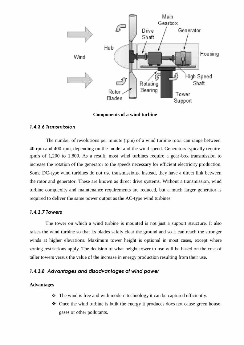
Components of a wind turbine
1.4.3.6 Transmission
The number of revolutions per minute (rpm) o f a wind turbine rotor can range between
40 rpm and 400 rpm, depending on the model and the wind speed. Generators typically require
rpm's of 1,200 to 1,800. As a result, most wind turbines require a gear-box transmission to
increase the rotation of the generator to the speeds necessary for efficient electricity production.
Some DC-type wind turbines do not use transmissions. Instead, they have a direct link between
the rotor and generator. These are known as direct drive systems. Without a transmission, wind
turbine complexity and maintenance requirements are reduced, but a much larger generator is
required to deliver the same power output as the AC-type wind turbines.
1.4.3.7 Towers
The tower on which a wind turbine is mounted is not just a support struct ure. It also
raises the wind turbine so that its blades safely clear the ground and so it can reach the stronger
winds at higher elevations. Maximum tower height is optional in most cases, except where
zoning restrictions apply. The decision of what height tower to use will be based on the cost of
taller towers versus the value of the increase in energy production resulting from their use.
1.4.3.8 Advantages and disadvantages of wind power
Advantages
The wind is free and with modern technology it can be captured efficiently.
Once the wind turbine is built the energy it produces does not cause green house
gases or other pollutants.
Although wind turbines can be very tall each takes up only a small plot of land.
Many people find wind farms an interesting feature of the landscape.
Remote areas that are not connected to the electricity power grid can use wind
turbines to produce their own supply.
Disadvantages
More noise
Threatening to Wildlife.
Wind is Unpredictable.
Limited Resource.
Inefficient.
Poor Television Reception.
Installation Cost is high.
1.4.4 Ocean Power
1.4.4.1 Tidal Energy Generation
Tidal energy, just like hydro energy transforms water in motion into a clean energy. The
motion of the tidal water, driven by the pull of gravity, contains large amounts of kinetic energy
in the form of strong tidal currents called tidal streams. The daily ebbing and flowing, back and
forth of the oceans tides along a coastline and into and out of small inlets, bays or coastal basins,
is little different to the water flowing down a river or stream. The movement of the sea water is
harnessed in a similar way using waterwheels and turbines to that used to generate hydro
electricity. But because the sea water can flow in both directions in a tidal energy system, it can
generate power when the water is flowing in and also when it is ebbing out. Therefore, tidal
generators are designed to produce power when the rotor blades are turning in either direction.
However, the costs of reversible electrical generators are more expensive than single direction
generators.

1.4.4.2 Different Types of Tidal Energy Systems
Tidal Barrage
Tidal Barrage:
A Tidal Barrage is a type of tidal power generation that involves the construction of a
fairly low dam wall, known as a ―barrage‖ and hence its name, across the entrance of a tidal
inlet or basin creating a tidal reservoir. This dam has a number of underwater tunnels cut into its
width allowing sea water to flow through them in a controllable way using ―sluice gates‖. Fixed
within the tunnels are huge water turbine generators that spin as the water rushes past them
generating tidal electricity. Tidal barrages generate electricity using the difference in the vertical
height between the incoming high tides and the outgoing low tides. As the tide ebbs and flows,
sea water is allowed to flow in or out of the reservoir through a one way underwater tunnel
system. This flow of tidal water back and forth causes the water turbine generators located
within the tunnels to rotate producing tidal energy with special generators used to produce
electricity on both the incoming and the outgoing tides.
Tidal Stream

Tidal Stream
A Tidal Stream Generation system reduces some of the environmental effects of tidal
barrages by using turbine generators under the surface of the water. Major tidal flows and ocean
currents, like the Gulf Stream, can be exploited to extract its tidal energy using underwater
rotors and turbines. Tidal stream generation is very similar in principal to wind power
generation, except this time water currents flow across turbines rotor blades which rotates the
turbine, much like how wind currents turn the blades for wind power turbines. In fact, tidal
stream generation areas on the sea bed can look just like underwater wind farms. Tidal streams
are formed by the horizontal fast flowing volumes of water caused by the ebb and flow of the
tide as the profile of the sea bed causes the water to speed up as it approaches the shoreline.
1.4.4.3 Advantages and disadvantages of Tidal Energy
Advantages
Tidal energy is a renewable energy resource because the energy it produces is
free and clean as no fuel is needed and no waste bi-products are produced.
Tidal energy has the potential to produce a great deal of free and green energy.
Tidal energy is not expensive to operate and maintain compared to other forms of
renewable energies.
Low visual impact as the tidal turbines are mainly if not totally submerged
beneath the water.
Low noise pollution as any sound generated is transmitted through the water.
Tidal barrages provide protection against flooding and land damage.
Large tidal reservoirs have multiple uses and can create recreational lakes and
areas where before there were none.
Disadvantages of Tidal Energy
Tidal energy is not always a constant energy source as it depends on the strength
and flow of the tides which themselves are affected by the gravitational effects of
the moon and the sun.
Tidal Energy requires a suitable site, where the tides and tidal streams are
consistently strong.
Must be able to withstand forces of nature resulting in high capital, construction
and maintenance costs.
High power distribution costs to send the generated power from the submerged
devices to the land using long underwater cables.
Danger to fish and other sea-life as they get stuck in the barrage or sucked
through the tidal turbine blades.
1.4.5 Wave energy
Waves are caused by the wind blowing over the surface of the ocean. In many areas of
the world, the wind blows with enough consistency and force to provide continuous waves along
the shoreline. Ocean waves contain tremendous energy potential. Wave power devices extract
energy from the surface motion of ocean waves or from pressure fluctuations below the
surface. Wave power varies considerably in different parts of the world. While an abundance
of wave energy is available, it cannot be fully harnessed everywhere for a variety of reasons,
such as other competing uses of the ocean (i.e. shipping, commercial fishing, naval operations)
or environmental concerns in sensitive areas. Therefore, it is important to consider how much
resource is recoverable in a given region.
1.4.6 Ocean thermal energy conversion (OTLC)
1.4.6.1 Closed-Cycle of OTLC
Closed-cycle systems use fluids with a low boiling point, such as ammonia, to rotate a
turbine to generate electricity. Warm surface seawater is pumped through a heat exchanger,
where the low-boiling-point fluid is vaporized. The expanding vapor turns the turbo-generator.
Cold deep seawater—which is pumped through a second heat exchanger—then condenses the
vapor back into a liquid that is then recycled through the system.
1.4.6.2 Open-Cycle of OTLC
Open-cycle systems use the tropical oceans' warm surface water to make electricity.
When warm seawater is placed in a low-pressure container, it boils. The expanding steam drives
a low-pressure turbine attached to an electrical generator. The steam, which has left its salt
behind in the low-pressure container, is almost pure, fresh water. It is condensed back into a
liquid by exposure to cold temperatures from deep-ocean water.
1.4.6.3 Hybrid OTLC
Hybrid systems combine the features of closed- and open-cycle systems. In a hybrid
system, warm seawater enters a vacuum chamber, where it is flash-evaporated into steam,
similar to the open-cycle evaporation process. The steam vaporizes a low-boiling-point fluid (in
a closed-cycle loop) that drives a turbine to produce electricity.
1.4.6.4 Complementary Technologies
OTEC has potential benefits beyond power production. For example, spent cold seawater
from an OTEC plant can chill fresh water in a heat exchanger or flow directly into a cooling
system. OTEC technology also supports chilled-soil agriculture. When cold seawater flows
through underground pipes, it chills the surrounding soil. The temperature difference between

plant roots in the cool soil and plant leaves in the warm air allows many plants that evolved in
temperate climates to be grown in the subtropics.
1.4.7 Biomass power plants
The most common types of boilers are hot water boilers and steam boilers. Wood chips,
residues and other types of biomass are used in the boilers, in the same way as coal, natural gas
and oil. Fuel is stored in a bunker for further transport to the boiler. In the boiler, water is heated
to high temperature under pressure. Steam from the boiler powers the turbine, which is
connected to the generator. Steam has passed through the turbine, heats area heat ing water,
which is distributed through the area heating network's piping. Co-firing biomass with coal
(replacing a portion of coal with biomass) is an effective method of using biomass for energy
purposes and to reduce CO2 emissions. Coal plants can be made suitable to replace part of the
coal by biomass or even to convert fully to biomass – turning a coal plant into a 100%
renewable energy plant.
1.4.7.1 Biomass used for electricity generation
Forest products: Woody biomass from multi-functional forests constitutes the majority
of today's biomass. Pellets and briquettes are manufactured by compressing by-products from
the forestry industry, such as sawdust, bark or small diameter wood. They are easy to transport
and therefore suitable for export.
Waste, by-products and residues: Residues include manure, sewage, sludge and other
degradable waste. Liquid biomass waste, such as manure, household waste and sewage plant
residues, can be digested to biogas.
Energy crops: Energy crops are not used on a large scale for electricity or heat
production today. As demand for sustainable biomass increases over time, such energy crops
may play a more important role in the future. Examples include woody short rotation
forestry/crops such as eucalyptus, poplar and willow. But also herbaceous (grassy) energy crops
such as miscanthus can be used. Especially with the use of energy crops, it is important to ensure
these plantations are established and managed in a sustainable manner.
1.4.8 Fuel cell
Fuel cell is a device that uses hydrogen (or hydrogen-rich fuel) and oxygen to create
electricity by an electrochemical process. A single fuel cell consists of an electrolyte sandwiched
between two thin electrodes (a porous anode and cathode). Hydrogen, or a hydrogen-rich fuel,
is fed to the anode where a catalyst separates hydrogen's negatively charged electrons from
positively charged ions (protons). At the cathode, oxygen combines with electrons and, in some
cases, with species such as protons or water, resulting in water or hydroxide ions, respectively.

The electrons from the anode side of the cell cannot pass through the membrane to the positively
charged cathode; they must travel around it via an electrical circuit to reach the other side of the
cell. This movement of electrons is an electrical current. The amount of power produced by a
fuel cell depends upon several factors, such as fuel cell type, cell size, the temperature at which
it operates, and the pressure at which the gases are supplied to the cell.
1.4.9 Hydrogen energy
Hydrogen can be considered as a clean energy carrier similar to electricity. Hydrogen
can be produced from various domestic resources such as renewable energy and nuclear energy.
In the long-term, hydrogen will simultaneously reduce the dependence on foreign oil and the
emission of greenhouse gases and other pollutants.
1.4.9.1 Hydrogen as an Energy Carrier
Hydrogen is considered as a secondary source of energy, commonly referred to as an
energy carrier. Energy carriers are used to move, store and deliver energy in a form that can be
easily used. Electricity is the most well-known example of an energy carrier. Hydrogen as an
important energy carrier in the future has a number of advantages. For example, a large volume
of hydrogen can be easily stored in a number of different ways. Hydrogen is also considered as a
high efficiency, low polluting fuel that can be used for transportation, heating, and power
generation in places where it is difficult to use electricity. In some instances, it is cheaper to ship
hydrogen by pipeline than sending electricity over long distances by wire.
1.4.9.2 Hydrogen Fuel Cell
Fuel cells directly convert the chemical energy in hydrogen to electricity, with pure
water and heat as the only byproducts. Hydrogen-powered fuel cells are not only pollution-free,
but a two to three fold increase in the efficiency can be experienced when compared to
traditional combustion technologies.

Hydrogen Fuel Cell
Fuel cells can power almost any portable devices that normally use batteries. Fuel cells
can also power transportation such as vehicles, trucks, buses, and marine vessels, as well as
provide auxiliary power to traditional transportation technologies. Hydrogen can play a
particularly important role in the future by replacing the imported petroleum we currently use in
our cars and trucks.
1.5. HYBRID RENEWABLE ENERGY SYSTEMS
Environmentally friendly power generation technologies will play an important role in
future power supply. The renewable energy technologies include power generation from
renewable energy sources, such as wind, PV(photovoltaic), MH(micro hydro), biomass, ocean
wave, geothermal and tides. In general, the key reason for the deployment of the above energy
systems are their benefits, such as supply security, reduced carbon emission, improved power
quality, reliability and employment opportunity to the local people. Since the renewable energy
resources are intermittent in nature therefore, hybrid combinations of two or more power
generation technologies, along with storage can improve system performance. Hybrid
Renewable Energy System (HRES) combines two or more renewable energy resources with
some conventional source (diesel or petrol generator) along with storage, in order to fulfill the
demand of an area. The intensity of the different energy sources into time is not the same. In
general, when one of the sources is intensive, the other tends to be extensive, i.e. the sources
complement one another. The distribution into time and the intensity of the energy sources
depend on the meteorological conditions of the chosen area, on the season, on the relief, etc. The
following definition of a hybrid system with renewable energy sources can be suggested. This is
a power system, using one renewable and one conventional energy source or more than one
renewable with or without conventional energy sources, that works in ―stand alone‖ or ―grid
connected‖ mode.

1.5.1 Hybrid Wind and Solar Electric Systems
Hybrid Wind and Solar Electric Systems
A hybrid renewable energy system utilizes two or more energy production methods,
usually solar and wind power. The major advantage of solar / wind hybrid system is that when
solar and wind power production is used together, the reliability of the system is enhanced.
Additionally, the size of battery storage can be reduced slightly as there is less reliance on one
method of power production. Often, when there is no sun, there is plenty of wind. It is ideally
suited to remote homes, schools and other off-grid applications. They can also be retrofitted to
existing diesel-generator systems to save on high fuel costs and minimize noise.
Because the peak operating times for wind and solar systems occur at different times of
the day and year, hybrid systems are more likely to produce power when need it. Many hybrid
systems are stand-alone systems, which operate "off-grid" -- not connected to an electricity
distribution system. For the times when neither the wind nor the solar system are producing,
most hybrid systems provide power through batteries and/or an engine generator powered by
conventional fuels, such as diesel. If the batteries run low, the engine generator can provide
power and recharge the batteries. Adding an engine generator makes the system more complex,
but modern electronic controllers can operate these systems automatically. An engine generator
can also reduce the size of the other components needed for the system. Keep in mind that the
storage capacity must be large enough to supply electrical needs during non-charging periods.
Battery banks are typically sized to supply the electric load for one to three days. Since hybrid
systems include both solar and wind power, they allow the power user to benefit from the
advantages provided of both forms of energy.

1.5.2 Advantages of Hybrid Energy System
Reductions in size of diesel engine and battery storage system, which can save the fuel
and reduce pollution.
Improves the load factors and help saving on maintenance and replacement costs.
The cost of electricity can be reduced by integrating diesel systems with renewable
power generation.
Renewable hybrid energy systems can reduce the cost of high-availability renewable
energy systems.