Embed Size (px)
Citation preview
M.I.E.T. ENGINEERING COLLEGE
(Approved by AICTE and Affiliated to Anna University Chennai)
TRICHY – PUDUKKOTTAI ROAD, TIRUCHIRAPPALLI – 620 007
DEPARTMENT OF COMPUTER SCIENCE
AND ENGINEERING
COURSE MATERIAL
CS6701 – CRYPTOGRAPHY AND NETWORK SECURITY
IV YEAR – VII SEMESTER

M.I.E.T. ENGINEERING COLLEGE
(Approved by AICTE and Affiliated to Anna University Chennai)
TRICHY – PUDUKKOTTAI ROAD, TIRUCHIRAPPALLI – 620 007
DEPARTMENT OF CSE
SYLLABUS (THEORY)
Sub. Code :CS6701 Branch / Year / Sem : CSE / IV / VII
Sub.Name : CRYPTOGRAPHY AND NETWORK SECURITY Staff Name :R.VENKATESAN
L T P C
3 0 0 3
UNIT I INTRODUCTION & NUMBER THEORY 10 Services, Mechanisms and attacks-the OSI security architecture-Network security model-Classical Encryption techniques (Symmetric cipher model, substitution techniques, transposition techniques, steganography).FINITE FIELDS AND NUMBER THEORY: Groups, Rings, Fields-Modular arithmetic- Euclid’s algorithm-Finite fields- Polynomial Arithmetic –Prime numbers-Fermat’s and Euler’s theorem- Testing for primality -The Chinese remainder theorem- Discrete logarithms.
UNIT II BLOCK CIPHERS & PUBLIC KEY CRYPTOGRAPHY 10 Data Encryption Standard-Block cipher principles-block cipher modes of operation-Advanced Encryption Standard (AES)-Triple DES-Blowfish-RC5 algorithm. Public key cryptography: Principles of public key cryptosystems-The RSA algorithm-Key management - Diffie Hellman Key exchange- Elliptic curve arithmetic-Elliptic curve cryptography.
UNIT III HASH FUNCTIONS AND DIGITAL SIGNATURES 8 Authentication requirement – Authentication function – MAC – Hash function – Security of hash function and MAC –MD5 - SHA - HMAC – CMAC - Digital signature and authentication protocols – DSS – EI Gamal – Schnorr.
UNIT IV SECURITY PRACTICE & SYSTEM SECURITY 8 Authentication applications – Kerberos – X.509 Authentication services - Internet Firewalls for Trusted System: Roles of Firewalls – Firewall related terminology- Types of Firewalls - Firewall designs - SET for E-Commerce Transactions. Intruder – Intrusion detection system – Virus and related threats – Countermeasures – Firewalls design principles – Trusted systems – Practical implementation of cryptography and security.
UNIT V E-MAIL, IP & WEB SECURITY 9 E-mail Security: Security Services for E-mail-attacks possible through E-mail - establishing keys privacy-authentication of the source-Message Integrity-Non-repudiation-Pretty Good Privacy-S/MIME. IPSecurity: Overview of IPSec - IP and IPv6-Authentication Header-Encapsulation Security Payload (ESP)-Internet Key Exchange (Phases of IKE, ISAKMP/IKE Encoding). Web Security: SSL/TLS Basic Protocol-computing the keys- client authentication-PKI as deployed by SSLAttacks fixed in v3- Exportability-Encoding-Secure Electronic Transaction (SET).
OUTCOMES: Upon Completion of the course, the students should be able to:
Compare various Cryptographic Techniques
Design Secure applications
Inject secure coding in the developed applications
TOTAL: 45 PERIODS

3
TEXT BOOKS:
1. William Stallings, Cryptography and Network Security, 6th Edition, Pearson Education, March 2013. (UNIT I,II,III,IV).
2. Charlie Kaufman, Radia Perlman and Mike Speciner, “Network Security”, Prentice Hall of India, 2002. (UNIT V).
REFERENCES: 1. Behrouz A. Ferouzan, “Cryptography & Network Security”, Tata Mc Graw Hill, 2007. 2. Man Young Rhee, “Internet Security: Cryptographic Principles”, “Algorithms and Protocols”, Wiley
Publications, 2003.
3. Charles Pfleeger, “Security in Computing”, 4th Edition, Prentice Hall of India, 2006. 4. Ulysess Black, “Internet Security Protocols”, Pearson Education Asia, 2000. 5. Charlie Kaufman and Radia Perlman, Mike Speciner, “Network Security, Second Edition, Private
Communication in Public World”, PHI 2002. 6. Bruce Schneier and Neils Ferguson, “Practical Cryptography”, First Edition, Wiley Dreamtech
India Pvt Ltd, 2003. 7. Douglas R Simson “Cryptography – Theory and practice”, First Edition, CRC Press, 1995. 8. http://nptel.ac.in/.
SUBJECT IN-CHARGE HOD
4
M.I.E.T. ENGINEERING COLLEGE
(Approved by AICTE and Affiliated to Anna University Chennai)
TRICHY – PUDUKKOTTAI ROAD, TIRUCHIRAPPALLI – 620 007
UNIT - I
INTRODUCTION
Computer data often travels from one computer to another, leaving the safety of
its protected physical surroundings. Once the data is out of hand, people with bad
intention could modify or forge your data, either for amusement or for their own benefit.
Cryptography can reformat and transform our data, making it safer on its trip
between computers. The technology is based on the essentials of secret codes, augmented
by modern mathematics that protects our data in powerful ways.
• Computer Security - generic name for the collection of tools designed to protect
data and to thwart hackers
• Network Security - measures to protect data during their transmission
• Internet Security - measures to protect data during their transmission over a
collection of interconnected networks
THE OSI SECURITY ARCHITECTURE
To assess effectively the security needs of an organization and to evaluate and choose
various security products and policies, the manager responsible for security needs some
systematic way of defining the requirements for security and characterizing the
approaches to satisfying those requirements. The OSI security architecture was developed
in the context of the OSI protocol architecture, which is described in Appendix H.
However, for our purposes in this chapter, an understanding of the OSI protocol
architecture is not required.
For our purposes, the OSI security architecture provides a useful, if abstract, overview of

5
many of t he concepts. The OSI security architecture focuses on secur ity
attacks, mechanisms, and services. These can be defined briefly as follows:
Threats and Attacks (RFC 2828)
Threat
A potential for violation of security, which exists when there is a circumstance,
capability, action, or event that could breach security and cause harm. That is, a threat is
a possible danger that might exploit a vulnerability.
Attack
An assault on system security that derives from an intelligent threat; that is, an intelligent
act that is a deliberate attempt (especially in the sense of a method or technique) to evade
security services and violate the security policy of a system.
Security Attacks, Services And Mechanisms
To assess the security needs of an organization effectively, the manager
responsible for security needs some systematic way of defining the requirements for
security and characterization of approaches to satisfy those requirements. One approach
is to consider three aspects of information security:
Security attack – Any action that compromises the security of information
owned by an organization.
Security mechanism – A mechanism that is designed to detect, prevent or
recover from a security attack.
Security service – A service that enhances the security of the data processing
systems and the info r mat ion transfers of an organization. The services
are intended to counter security attacks and they make use of one or more
security mechanisms to provide the service.
SECURITY SERVICES
The classification of security services are as follows:
Confidentiality: Ensures that the information in a computer system and
transmitted information are accessible only for reading by authorized parties.
Eg., printing, displaying and other forms of disclosure.
Authentication: Ensures that the origin of a message or electronic document is

6
correctly identified, with an assurance that the identity is not false.
Integrity: Ensures that only authorized parties are able to modify computer
system assets and transmitted information. Modification includes writing,
changing status, deleting, creating and delaying or replaying of transmitted
messages.
Non repudiation: Requires that neither the sender nor the receiver of a message
be able to deny the transmission.
Access control: Requires that access to information resources may be controlled
by or the target system.
Availability: Requires that computer system assets be available to authorized
parties when needed.
Security Services (X.800)
AUTHENTICATION
The assurance that the communicating entity is the one that it claims to be.
Peer Entity Authentication
Used in association with a logical connection to provide confidence in the identity of the
entities connected.
Data Origin Authentication
In a connectionless transfer, provides assurance that the source of received data is as
claimed.
ACCESS CONTROL
The prevention of unauthorized use of a resource (i.e., this service controls who can have
access to a resource, under what conditions access can occur, and what those accessing
the resource are allowed to do).
DATA CONFIDENTIALITY
The protection of data from unauthorized disclosure.
Connection Confidentiality
The protection of all user data on a connection.
Connectionless Confidentiality
The protection of all user data in a single data block
7
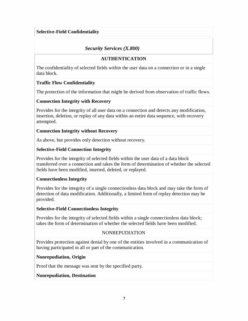
Selective-Field Confidentiality
Security Services (X.800)
AUTHENTICATION
The confidentiality of selected fields within the user data on a connection or in a single
data block.
Traffic Flow Confidentiality
The protection of the information that might be derived from observation of traffic flows.
Connection Integrity with Recovery
Provides for the integrity of all user data on a connection and detects any modification,
insertion, deletion, or replay of any data within an entire data sequence, with recovery
attempted.
Connection Integrity without Recovery
As above, but provides only detection without recovery.
Selective-Field Connection Integrity
Provides for the integrity of selected fields within the user data of a data block
transferred over a connection and takes the form of determination of whether the selected
fields have been modified, inserted, deleted, or replayed.
Connectionless Integrity
Provides for the integrity of a single connectionless data block and may take the form of
detection of data modification. Additionally, a limited form of replay detection may be
provided.
Selective-Field Connectionless Integrity
Provides for the integrity of selected fields within a single connectionless data block;
takes the form of determination of whether the selected fields have been modified.
NONREPUDIATION
Provides protection against denial by one of the entities involved in a communication of
having participated in all or part of the communication.
Nonrepudiation, Origin
Proof that the message was sent by the specified party.
Nonrepudiation, Destination

Security Services (X.800)
AUTHENTICATION
Proof that the message was received by the specified party.
SECURITY MECHANISMS
One of the most specific security mechanisms in use is cryptographic techniques.
Encryption or encryption-like transformations of information are the most common
means of providing security. Some of the mechanisms are
Encipherment
Digital Signature
Access Control
A security mechanism is a process (or a device incorporating such a process) that can be
used in a system to implement a security service that is provided by or within the system.
Some
examples of security mechanisms are authentication exchange, checksums, digital
signatures,encryption and traffic padding (cf. p.153, RFC 2828).
Security mechanisms are divided into two groups: specific security mechanisms, which
may be incorporated in a specific protocol layer, and pervasive security mechanisms, which
are not specific to any particular protocol layer.
The concepts below are taken from the X.800 Recommendations Specific security
mechanisms
– Encipherment: encipherment can provide confidentiality of either data or traffic flow
information by converting the original information into a form that is not intelligible.
Encipherment algorithms may be reversible or irreversible. Two general classifications of
reversible encipherment algorithm are symmetric (i.e. secret key) and asymmetric
(i.e.public key).
– Digital signature: this mechanism attaches some special information to the transmitted
data, enabling the recipient to verify the source as well as the integrity of the data. The term
digital signature goes hand-in-hand with public key cryptography.
– Access control: this mechanism may use the authenticated identity of an entity,
information about the entity or capabilities of the entity to grant access rights to the entity.
– Data integrity: two aspects of data integrity are: (i) the integrity of a single data unit or
field; (ii) the integrity of a stream of data units or fields. In general, different mechanisms
are used to provide these two types of integrity service, although provision of the second
without the first is not practical.
– Authentication exchange: peer entity authentication is assisted by means of information
exchange.
– Traffic padding mechanism: traffic padding mechanisms can be used to provide various
levels of protection against traffic analysis. Traffic padding is done by inserting bits into
gaps in data streams.
– Routing control: this mechanism allows a proper choice of routes for transferring
information. End systems may wish to instruct the network service provider to establish a
connection via a different route for a more secure communication.
– Notarization mechanism: this mechanism needs the involvement of a third party to ensure
certain properties of data exchange between the two entities.
• Pervasive security mechanisms
– Trusted functionality: may be used to extend the scope, or to establish the effectiveness,
of other security mechanisms. Any functionality which provides access to security
mechanisms should be trustworthy.
– Security labels: resources including data items may have security labels associated with
them, e.g. to indicate a sensitivity level. It is often necessary to convey the appropriate
security label with data in transit.
– Event detection: security-relevant event detection includes the detection of apparent
violations of security and may also include detection of ‗normal‘ events
– Security audit trails: provide a valuable security mechanism, as potentially they permit
detection and investigation of breaches of security by permitting a subsequent security
audit. A security audit is an independent review and examination of system records and
activities in order to test for adequacy of system controls, to ensure compliance with
established policy and operational procedures, to aid in damage assessment and to
recommend any indicated changes in controls, policy and procedures.
– Security recovery: security recovery deals with requests from mechanisms such as event
handling and management functions and takes recovery actions as the result of applying a
set of rules. These recovery actions may be of three kinds: immediate, temporary or long
term.
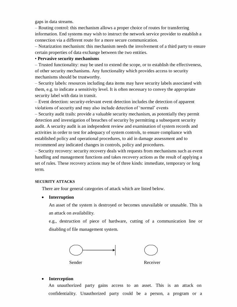
SECURITY ATTACKS
There are four general categories of attack which are listed below.
Interruption
An asset of the system is destroyed or becomes unavailable or unusable. This is
an attack on availability.
e.g., destruction of piece of hardware, cutting of a communication line or
disabling of file management system.
Sender Receiver
Interception
An unauthorized party gains access to an asset. This is an attack on
confidentiality. Unauthorized party could be a person, a program or a

computer.e.g., wire tapping to capture data in the network, illicit copying of files
Sender Receiver
Eavesdropper or forger
Modification
An unauthorized party not only gains access to but tampers with an asset. This is
an attack on integrity.
e.g., changing values in data file, altering a program, modifying the contents of
messages being transmitted in a network.
Sender Receiver
Eavesdropper or forger
Fabrication
An unauthorized party inserts counterfeit objects into the system. This is an attack
on authenticity.
e.g., insertion of spurious message in a network or addition of records to a file.
Sender Receiver
Eavesdropper or forger
A useful categorization of these attacks is in terms of
Passive attacks
Active attacks
Passive attack

Passive attacks are in the nature of eavesdropping on, or monitoring of, transmissions.
The goal of the opponent is to obtain information that is being transmitted. Passive
attacks are of two types:
Release of message contents: A telephone conversation, an e-mail message and a
transferred file may contain sensitive or confidential information. We would like
to prevent the opponent from learning the contents of these transmissions.
Traffic analysis: If we had encryption protection in place, an opponent might still
be able to observe the pattern of the message. The opponent could determine the
location and identity of communication hosts and could observe the frequency
and length of messages being exchanged. This information might be useful in
guessing the nature of communication that was taking place.
Passive attacks are very difficult to detect because they do not involve any alteration
of data. However, it is feasible to prevent the success of these attacks.
Active attacks
These attacks involve some modification of the data stream or the creation of a false
stream. These attacks can be classified in to four categories:
Masquerade – One entity pretends to be a different entity.
Replay – involves passive capture of a data unit and its subsequent transmission
to produce an unauthorized effect.
Modification of messages – Some portion of message is altered or the messages
are delayed or recorded, to produce an unauthorized effect.
Denial of service – Prevents or inhibits the normal use or management of
communication facilities. Another form of service denial is the disruption of an
entire network, either by disabling the network or overloading it with messages so
as to degrade performance.
It is quite difficult to prevent active attacks absolutely, because to do so would require
physical protection of all communication facilities and paths at all times. Instead, the goal
is to detect them and to recover from any disruption or delays caused by them.
Symmetric and public key algorithms
Encryption/Decryption methods fall into two categories.
Symmetric key
Public key
In symmetric key algorithms, the encryption and decryption keys are known both to

sender and receiver. The encryption key is shared and the decryption key is easily
calculated from it. In many cases, the encryption and decryption keys are the same.
In public key cryptography, encryption key is made public, but it is
computationally infeasible to find the decryption key without the information known to
the receiver.
A MODEL FOR NETWORK SECURITY
A message is to be transferred from one party to another across some sort of internet. The
two parties, who are the principals in this transaction, must cooperate for the exchange to
take place. A logical information channel is established by defining a route through the
internet from source to destination and by the cooperative use of communication
protocols (e.g., TCP/IP) by the two principals.
using this model requires us to:
– design a suitable algorithm for the security transformation
– generate the secret information (keys) used by the algorithm
– develop methods to distribute and share the secret information
– specify a protocol enabling the principals to use the transformation and
secret information for a security service
MODEL FOR NETWORK ACCESS SECURITY

• using this model requires us to:
– select appropriate gatekeeper functions to identify users
– implement security controls to ensure only authorised users access
designated information or resources
• trusted computer systems can be used to implement this model
CONVENTIONAL ENCRYPTION
• referred conventional / private-key / single-key
• sender and recipient share a common key
• all classical encryption algorithms are private-key
• was only type prior to invention of public-key in 1970‟plaintext - the original
message
Some basic terminologies used :
• ciphertext - the coded message
• cipher - algorithm for transforming plaintext to ciphertext
• key - info used in cipher known only to sender/receiver
• encipher (encrypt) - converting plaintext to ciphertext
• decipher (decrypt) - recovering ciphertext from plaintext
• cryptography - study of encryption principles/methods
• cryptanalysis (codebreaking) - the study of principles/ methods of deciphering
ciphertext without knowing key
• cryptology - the field of both cryptography and cryptanalysis.

Here the original message, referred to as plaintext, is converted into apparently
random nonsense, referred to as cipher text. The encryption process consists of an
algorithm and a key. The key is a value independent of the plaintext. Changing the key
changes the output of the algorithm. Once the cipher text is produced, it may be
transmitted. Upon reception, the cipher text can be transformed back to the original
plaintext by using a decryption algorithm and the same key that was used for encryption.
The security depends on several factors. First, the encryption algorithm must be powerful
enough that it is impractical to decrypt a message on the basis of cipher text alone.
Beyond that, the security depends on the secrecy of the key, not the secrecy of the
algorithm.
• Two requirements for secure use of symmetric encryption:
– a strong encryption algorithm
– a secret key known only to sender / receiver
Y = EK(X)
X = DK(Y)
• assume encryption algorithm is known
• implies a secure channel to distribute key

Figure: conventional cryptosystem
A source produces a message in plaintext, X = [X1, X2, … , XM] where M are
the number of letters in the message. A key of the form K = [K1, K2, …, KJ] is
generated. If the key is generated at the source, then it must be provided to the destination
by means of some secure channel.
With the message X and the encryption key K as input, the encryption algorithm
forms the cipher text Y = [Y1, Y2, …, YN]. This can be expressed as
Y = EK(X)
The intended receiver, in possession of the key, is able to invert the
transformation:
X = DK(Y)
An opponent, observing Y but not having access to K or X, may attempt to
recover X or K or both. It is assumed that the opponent knows the encryption and
decryption algorithms. If the opponent is interested in only this particular message, then
the focus of effort is to recover X by generating a plaintext estimate. Often if the
opponent is interested in being able to read future messages as well, in which case an
attempt is made to recover K by generating an estimate.
Cryptography
Cryptographic systems are generally classified along 3 independent dimensions:
Type of operations used for transforming plain text to cipher text
All the encryption algorithms are abased on two general principles: substitution,
in which each element in the plaintext is mapped into another element, and
transposition, in which elements in the plaintext are rearranged.
The number of keys used
If the sender and receiver uses same key then it is said to be symmetric key (or)
single key (or) conventional encryption.
If the sender and receiver use different keys then it is said to be public key
encryption.

The way in which the plain text is processed
A block cipher processes the input and block of elements at a time, producing
output block for each input block.
A stream cipher processes the input elements continuously, producing output
element one at a time, as it goes along.
Cryptanalysis
The process of attempting to discover X or K or both is known as cryptanalysis.
The strategy used by the cryptanalysis depends on the nature of the encryption scheme
and the information available to the cryptanalyst.
There are various types of cryptanalytic attacks based on the amount of
information known to the cryptanalyst.
Cipher text only – A copy of cipher text alone is known to the cryptanalyst.
Known plaintext – The cryptanalyst has a copy of the cipher text and the
corresponding plaintext.
Chosen plaintext – The cryptanalysts gains temporary access to the encryption
machine. They cannot open it to find the key, however; they can encrypt a large
number of suitably chosen plaintexts and try to use the resulting cipher texts to
deduce the key.
Chosen cipher text – The cryptanalyst obtains temporary access to the
decryption machine, uses it to decrypt several string of symbols, and tries to use
the results to deduce the key.
STEGANOGRAPHY
A plaintext message may be hidden in any one of the two ways. The methods of
steganography conceal the existence of the message, whereas the methods of
cryptography render the message unintelligible to outsiders by various transformations of
the text.
A simple form of steganography, but one that is time consuming to construct is
one in which an arrangement of words or letters within an apparently innocuous text
spells out the real message.
e.g., (i) the sequence of first letters of each word of the overall message spell out the real
(Hidden) message.
(ii) Subset of the words of the overall message is used to convey the hidden message.
Various other techniques have been used historically, some of them are

Character marking – selected letters of printed or typewritten text are overwritten
in pencil. The marks are ordinarily not visible unless the paper is held to an angle
to bright light.
Invisible ink – a number of substances can be used for writing but leave no visible
trace until heat or some chemical is applied to the paper.
Pin punctures – small pin punctures on selected letters are ordinarily not visible
unless the paper is held in front of the light.
Typewritten correction ribbon – used between the lines typed with a black ribbon,
the results of typing with the correction tape are visible only under a strong light.
Drawbacks of steganography
Requires a lot of overhead to hide a relatively few bits of information.
Once the system is discovered, it becomes virtually worthless.
CLASSICAL ENCRYPTION TECHNIQUES
There are two basic building blocks of all encryption techniques: substitution and
transposition.
I .SUBSTITUTION TECHNIQUES
A substitution technique is one in which the letters of plaintext are replaced by other
letters or by numbers or symbols. If the plaintext is viewed as a sequence of bits, then
substitution involves replacing plaintext bit patterns with cipher text bit patterns.
(i)Caesar cipher (or) shift cipher
The earliest known use of a substitution cipher and the simplest was by Julius
Caesar. The Caesar cipher involves replacing each letter of the alphabet with the letter
standing 3 places further down the alphabet.
e.g., plain text : pay more money
Cipher text: SDB PRUH PRQHB
Note that the alphabet is wrapped around, so that letter following „z‟ is „a‟.
For each plaintext letter p, substitute the cipher text letter c such that
C = E(p) = (p+3) mod 26
A shift may be any amount, so that general Caesar algorithm is
C = E (p) = (p+k) mod 26

Where k takes on a value in the range 1 to 25. The decryption algorithm is simply
P = D(C) = (C-k) mod 26
(ii)Playfair cipher
The best known multiple letter encryption cipher is the playfair, which treats
digrams in the plaintext as single units and translates these units into cipher text digrams.
The playfair algorithm is based on the use of 5x5 matrix of letters constructed using a
keyword. Let the keyword be „monarchy‟. The matrix is constructed by filling in the
letters of the keyword (minus duplicates) from left to right and from top to bottom, and
then filling in the remainder of the matrix with the remaining letters in alphabetical order.
The letter „i‟ and „j‟ count as one letter. Plaintext is encrypted two letters at a time
according to the following rules:
Repeating plaintext letters that would fall in the same pair are separated with a
filler letter such as „x‟.
Plaintext letters that fall in the same row of the matrix are each replaced by the
letter to the right, with the first element of the row following the last.
Plaintext letters that fall in the same column are replaced by the letter beneath,
with the top element of the column following the last.
Otherwise, each plaintext letter is replaced by the letter that lies in its own row
and the column occupied by the other plaintext letter.
M O N A R
C H Y B D
E F G I/J K
L P Q S T
U V W X Z
Plaintext = meet me at the school house
Splitting two letters as a unit => me et me at th es ch ox ol ho us ex
Corresponding cipher text => CL KL CL RS PD IL HY AV MP HF XL IU
Strength of playfair cipher
Playfair cipher is a great advance over simple mono alphabetic ciphers.
Since there are 26 letters, 26x26 = 676 diagrams are possible, so identification of
individual digram is more difficult.

Frequency analysis is much more difficult.
(iii) Hill Cipher:
Polygraphic substitution cipher.
Uses matrices to encrypt and decrypt.
Uses modular arithmetic (Mod 26).
Encryption:
The encryption algorithm takes m sucessive plaintext letters and subsitutes for them
m ciphertext letters.
Assign each letter in alphabet a number between 0 and 25
Change message into 2 x 1 letter vectors
Change each vector into 2 x 1 numeric vectors
Multiply each numeric vector by encryption matrix
Convert product vectors to letters
Message to encrypt = HELLO WORLD

HELLO WORLD has been encrypted to SLHZY ATGZT
Decryption :
Change message into 2 x 1 letter vectors
Change each vector into 2 x 1 numeric vectors
Multiply each numeric vector by decryption matrix (inverse of the matrix K used in
encryption )
Convert new vectors to letters.
(iv)Polyalphabetic ciphers
Another way to improve on the simple monoalphabetic technique is to use
different monoalphabetic substitutions as one proceeds through the plaintext message.
The general name for this approach is polyalphabetic cipher. All the techniques have the
following features in common.
A set of related monoalphabetic substitution rules are used
A key determines which particular rule is chosen for a given transformation.
(v)Vigenere cipher
In this scheme, the set of related monoalphabetic substitution rules consisting of
26 caesar ciphers with shifts of 0 through 25. Each cipher is denoted by a key letter. e.g.,
Caesar cipher with a shift of 3 is denoted by the key value 'd‟ (since a=0, b=1, c=2 and so
on). To aid in understanding the scheme, a matrix known as vigenere tableau is
constructed.
PLAIN TEXT
K
E
Y
L
E
T
T
E
R
S
a b c d e F g h i j k … x y z
a A B C D E F G H I J K … X Y Z
b B C D E F G H I J K L … Y Z A
c C D E F G H I J K L M … Z A B
d D E F G H I J K L M N … A B C
e E F G H I J K L M N O … B C D
f F G H I J K L M N O P … C D E
g G H I J K L M N O P Q … D E F
:
:
:
:
:
:
:
:
:
:
:
:
:
:
:
:
:
:
:
:
:
:
:
:
… :
:
:
:
:
:
x X Y Z A B C D E F G H … W
y Y Z A B C D E F G H I … X
z Z A B C D E F G H I J … Y

Each of the 26 ciphers is laid out horizontally, with the key letter for each cipher
to its left. A normal alphabet for the plaintext runs across the top. The process of
encryption is simple: Given a key letter X and a plaintext letter y, the cipher text is at the
intersection of the row labeled x and the column labeled y; in this case, the ciphertext is
V.
To encrypt a message, a key is needed that is as long as the message. Usually, the
key is a repeating keyword.
e.g., key = d e c e p t i v e d e c e p t i v e d e c e p t i v e
PT = w e a r e d i s c o v e r e d s a v e y o u r s e l f
CT = ZICVTWQNGRZGVTWAVZHCQYGLMGJ
Decryption is equally simple. The key letter again identifies the row. The position
of the cipher text letter in that row determines the column, and the plaintext letter is at the
top of that column.
Strength of Vigenere cipher
o There are multiple cipher text letters for each plaintext letter.
o Letter frequency information is obscured.
One Time Pad Cipher
It is an unbreakable cryptosystem. It represents the message as a sequence of 0s
and 1s. this can be accomplished by writing all numbers in binary, for example, or by
using ASCII. The key is a random sequence of 0‟s and 1‟s of same length as the message.
Once a key is used, it is discarded and never used again. The system can be expressed as
follows:
Ci = Pi Ki
Ci - ith
binary digit of cipher text
Pi - ith
binary digit of plaintext
Ki - ith
binary digit of key
– exclusive OR operation
Thus the cipher text is generated by performing the bitwise XOR of the plaintext and the
key. Decryption uses the same key. Because of the properties of XOR, decryption simply
involves the same bitwise operation:
Pi = Ci Ki
e.g., plaintext = 0 0 1 0 1 0 0 1
Key = 1 0 1 0 1 1 0 0
-------------------

ciphertext = 1 0 0 0 0 1 0 1
Advantage:
Encryption method is completely unbreakable for a cipher text only
attack. Disadvantages
It requires a very long key which is expensive to produce and expensive to
transmit.
Once a key is used, it is dangerous to reuse it for a second message; any
knowledge on the first message would give knowledge of the second.
II .TRANSPOSITION TECHNIQUES
A transposition cipher does not substitute one symbol for another; instead it
changes the location of the symbols.
All the techniques examined so far involve the substitution of a cipher text
symbol for a plaintext symbol. A very different kind o f mapping is achieved by
performing some sort of permutation on the plaintext letters. This technique is referred to
as a transposition cipher.
Rail fence is simplest of such cipher, in which the plaintext is written down as a
sequence of diagonals and then read off as a sequence of rows.
Plaintext = meet at the school house
To encipher this message with a rail fence of depth 2, we write the message as
follows:
m e a t e c o l o s
e t t h s h o h u e
The encrypted message is
MEATECOLOSETTHSHOHUE
Row Transposition Ciphers-A more complex scheme is to write the message in
a rectangle, row by row, and read the message off, column by column, but permute the
order of the columns. The order of columns then becomes the key of the algorithm.
e.g., plaintext = meet at the school house
Key = 4 3 1 2 5 6 7
PT = m e e t a t t
h e s c h o o
l h o u s e
CT = ESOTCUEEHMHLAHSTOETO
A pure transposition cipher is easily recognized because it has the same letter

frequencies as the original plaintext. The transposition cipher can be made significantly
more secure by performing more than one stage of transposition. The result is more
complex permutation that is not easily reconstructed.
LFSR sequences:
A linear-feedback shift register (LFSR) is a shift register whose input bit is a linear
function of its previous state.
The most commonly used linear function of single bits is exclusive-or (XOR).
Thus, an LFSR is most often a shift register whose input bit is driven by the XOR of some
bits of the overall shift register value.
The initial value of the LFSR is called the seed, and because the operation of the
register is deterministic, the stream of values produced by the register is completely
determined by its current (or previous) state. Likewise, because the register has a finite
number of possible states, it must eventually enter a repeating cycle. However, an LFSR
with a well-chosen feedback function can produce a sequence of bits which appears
random and which has a very long cycle.
Both hardware and software implementations of LFSRs are common.
The mathematics of a cyclic redundancy check, used to provide a quick check
against transmission errors, are closely related to those of an LFSR.
Applications:
Generating pseudo-random numbers, pseudo-noise sequences, fast digital counters, and
whitening sequences.
Basic Number Theory :
Basic Notions:
Divisibility:
Let a and b be integers with a ≠0. We say that a divides b,if there is an integer
k such that b = ak. This is denoted by a|b. Another way to express this is that b is a
multiple of a.
Example :
3/ 15, —15|60, 7 /18 (does not divide).
Prime Numbers:
A number p > 1 th at is divisible only by 1 and itself is called a p rim en u m b
e r.The first few primes are 2,3,5, 7,11,13,17, … . An integer n > 1th at is not prime is
called composite , which means th at n must expressibleas a product ab of integers with 1
< a, b < n.
Prime Factorisation
• to factor a number n is to write it as a product of other numbers: n=a × b × c
• note that factoring a number is relatively hard compared to multiplying the factors
together to generate the number
• the prime factorisation of a number n is when its written as a product of primes
– eg. 91=7×13 ; 3600=24×3
2×5
2
Relatively Prime Numbers & GCD
• two numbers a, b are relatively prime if have no common divisors apart from 1
– eg. 8 & 15 are relatively prime since factors of 8 are 1,2,4,8 and of 15 are
1,3,5,15 and 1 is the only common factor
• conversely can determine the greatest common divisor by comparing their prime
factorizations and using least powers
– eg. 300=21×3
1×5
2 18=2
1×3
2 hence GCD(18,300)=2
1×3
1×5
0=6
Greatest Common Divisor:
The g r e a te s t co m m o n d iv iso r of a ond b is the largest positive
integer dividing both a aiid b and is denoted by either gcd(a, b)or by (a, b). In thisbook,
we shall use the first notation.
Example 1 : gcd(6, 4) = 2, gcd(5, 7) = 1, gcd(24, GO) = 12.
Euclidean Algorithm to find GCD :
Suppose a and b are large numbers, so it might not be easy to factorthem. The
gcd can be calculated by a procedure known as the Eucldean algorithm .
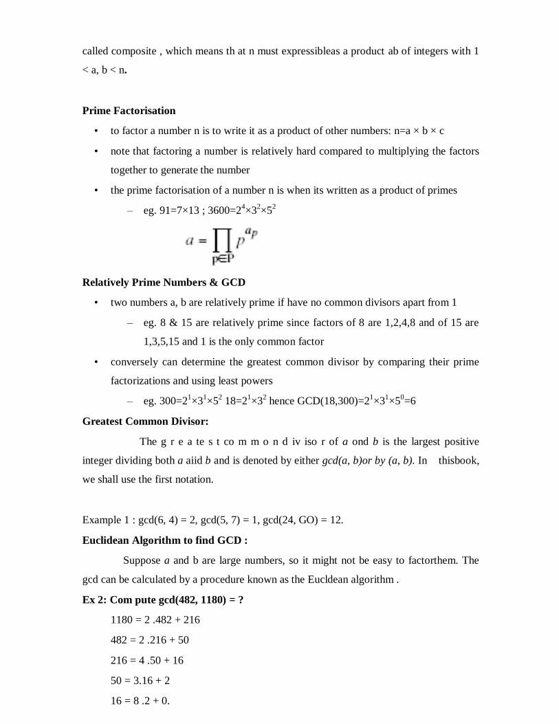
Ex 2: Com pute gcd(482, 1180) = ?
1180 = 2 .482 + 216
482 = 2 .216 + 50
216 = 4 .50 + 16
50 = 3.16 + 2
16 = 8 .2 + 0.

Therefore,gcd(482,1180) = 2.
Ex 3: gcd(12345,11111)= ?
12345 = 1.11111+ 1234
11111 = 9 .1234 + 5
1234 = 246 • 5+ 4
5 = 1 • 4 + 1
4 = 4.1 + 0
Therefore, gcd(12345,11111) = 1.
Congruences:
Let a ,b ,n be integers with n ≠0 . We say that a≡b (mod n). (a is congruent to b
mod n )
Example :
27≡?(mod 5)
27≡2(mod 5)
Proposition:
Let a, b, c, n be integers with n ≠ 0.
1 . a ≡b (mod n) if and only if n\a.
2 . a ≡a (mod n).
3 . a ≡b (mod n) if and only i f b ≡ a (mod n).
4 . If a ≡ b and b ≡c (mod n), then a ≡ c (mod n).
Modular exponentiation:
Modular exponentiation is a type of exponentiation performed over a modulus. It is useful
in computer science, especially in the field of public-key cryptography.
The operation of modular exponentiation calculates the remainder when an integer
b (the base) raised to the eth power (the exponent), be, is divided by a positive integer m
(the modulus).
In symbols, given base b, exponent e, and modulus m, the modular exponentiation
c is: c ≡ be (mod m).
For example,
given b = 5, e = 3 and m = 13, the solution c = 8 is the remainder of dividing 53 = 125 by
13.
Given integers b and e, and a positive integer m, a unique solution c exists with the
property 0 ≤ c < m.

E.g. To find 1113
mod 53
13 = 8 + 4 + 1 so 1113
= 118+4+1
= 118 * 11
4 * 11
1
We can compute successive squares of 11 to obtain 11, 112, 11
4, 11
8 and then multiply
together 111 * 11
4 * 11
8 to get the answer 11
13 .
Because we are working mod 53, we will ―take mods‖ at every stage of the calculation.
Thus we have:
11 mod 53 = 11
112 = 121, 121 mod 53 = 121 – 2*53 = 15
114 = (11
2)2 = 15
2 mod 53 = 225 mod 53 = 225 – 4*53 = 13
118 = (11
4)2 = 13
2 mod 53 = 169 mod 53 = 169 – 3*53 = 10
Therefore 1113
mod 53 = 11 * 13 * 10 = 1430 mod 53 = 1430 – 26*53 = 52
The answer is 1113
mod 53 = 52
Chinese Remainder Theorem .
Suppose gcd(m, n) = 1. Given integersa and b, there exists exactly one solution
x (mod m n) to the simultaneous congruences.
x ≡a (mod m)
x ≡ b (mod n).
Chinese Rem ainder Theorem (General Form).
Let m1,…….,mk be integers with gcd(mi, mj) = 1 whenever i≠j . Given
integers a1,………ak,there exists exactly one solution x (mod m1,….,mk)to the
simultaneous congruences.
x ≡ a1 (mod m1), x ≡ a2 (mod m2),………, x ≡ ak (mod mk)
• used to speed up modulo computations
• working modulo a product of numbers
– eg. mod M = m1m2..mk
• Chinese Remainder theorem lets us work in each moduli mi separately
• since computational cost is proportional to size, this is faster than working in the
full modulus M


Multiplicative inverse:
General format:
Example:
3x mod 7=1 find the value of x?

Fermats theorem:
If p is a prime and a is the positive integer and not divisible by p, then a^p-1( mod
p)=1,or a^p-1 ≡1 (mod p ).
Example: a=7,p=3:
73-1 mod 3
72 mod 3
49 mod 3=1
It satisfies the fermat‘s theorem.
Euler’s theorem:
If gcd(a,n)=1,then a ɸ(n)
≡1(mod n).
ɸ(n)=eulers totient function.
Euler Totient Function ø(n)
• Defn:number of positive integers less than n and relatively prime to n
• reduced set of residues is those numbers (residues) which are relatively prime to n
– eg for n=10(1*2*5),
– complete set of residues is
{1,2(2*1),3(1*3),4(1*2),5(1*5),6(1*2*3),7(1*7),8(1*2*4),9(1*3*3)}
– reduced set of residues is {1,3,7,9}
• number of elements in reduced set of residues is called the Euler Totient Function
ø(n)

• to compute ø(n) need to count number of elements to be excluded
• in general need prime factorization, but
– for p (p prime) ø(p) = p-1
– for p.q (p,q prime) ø(p.q) = (p-1)(q-1)
• eg.
– ø(37) = 36
– ø(21) = (3–1)×(7–1) = 2×6 = 12
In general we need prime factorization
For p(p prime) ɸ(p)=p-1
For p,q(p,q prime) ɸ(p,q)=(p-1)(q-1),
Example 1: ɸ(37)=36
Example 2:ɸ(21)=7×3
ɸ(7,3)=(7-1).(3-1)
=(6).(2)=12
ɸ(7,3)=12.
Legendre and Jacobi symbol:
Legendre symbol:
Let p be an odd prime and let a be an integer with a ≠0(mod p).Then a( p-
1 )/2 ≡ ±1 (mod p).
The congruence,
x2≡ a (mod p) has a solution if and only a
(p-1)/2≡1(mod p).
then the legender symbol
(a/p)={+1 if x2 ≡ a (mod p) has a solution,
-1 if x2 ≡ a (mod p) has no solution} (or)
represents the Legendre symbol, defined for all integers and all odd primes by

Proposition:
Let p be an odd prime.
(i)if a≡b≡0(mod p),then
(a/p)=(b/p)
(ii)if a≡0(mod p),then
( a/p)≡a(p-1)/2
(mod p)
(iii)if ab≠0(mod p),then,(ab/p)=(a/p)(b/p)
(-1/p)=(-1)(p-1)/2
Jacobi symbol:
For any integer and any positive odd integer , the Jacobi symbol is defined as the
product of the Legendre symbols corresponding to the prime factors of :
Theorem: Let n be odd.
1.If a≡b (mod n) and gcd(a,n)=1 then
2. if gcd(ab,n)=1, then
3. (-1/n) = (-1) (n-1)/2
.
4.
5. Let m be odd with gcd(m,n)=1. Then
(m/n) = (- (n/m) if m≡n≡3 (mod 4)
= +(n/m) otherwise.
Example:
Given that is prime, calculate
Using the Legendre symbol

Using the Jacobi symbol
Finite Fields:
A finite field or Galois field (so-named in honour of Évariste Galois) is a field that
contains a finite number of elements. As with any field, a finite field is a set on which the
operations of multiplication, addition, subtraction and division are defined and satisfy
certain basic rules. The most common examples of finite fields are given by the integers
mod n when n is a prime number.
The number of elements of a finite field is called its order.
A field is a set containing elements 0and 1(with 1≠0) and satisfying the following:
(i)It has a multiplication and addition satisfying
1.0+x=x for all x
2.1.x=x for all x
3.Addition and multiplication are commutative ,associative and distributive law.
(ii)Every element has a additive inverse(for each x,this means there exist an element x such
that x+(-x)=0.
(iii)Every nonzero element has a multiplicative inverse.
Example:
GF(4)={0,1,ω,ω2} with the following laws:
(i)0+x=x for all x.
(ii)x+x=0 for all x.

(iii)1.x=x for all x.
(iv)ω+1=ω2 .
(v)Addition and multiplication are commutative ,associative and distributive
Example 1: Divide x2+x+1 into x4+x3+1
x2+1
x2+x+1 x
4+x
3+1
x4+x
3+x
2
x2+1
x2+x+1
1+x
Example 2: GF(28)
b7x7+b6x
6+b5x
5+b4x
4+b3x
3+b2x
2+b1x
1+b0.
bi=0 or 1
8bits=b7b6b5b4b3b2b1b0
x7+x
6+x
3+x+1=11001011
x4+x
3+1=00011001
11010010
Example:3 Multiply x7+x
6+x
3+x+1 by x.
Steps:
(i)shift left and append a zero as the last bit.
(ii)if the first bit 0 stop.
(iii)if the first bit 1 XOR with 100011011.
Continued Fraction:
A continued fraction is an expression obtained through an iterative process of
representing a number as the sum of its integer part and the reciprocal of another number,
then writing this other number as the sum of its integer part and another reciprocal, and so

on.
In a finite continued fraction (or terminated continued fraction), the
iteration/recursion is terminated after finitely many steps by using an integer in lieu of
another continued fraction. In contrast, an infinite continued fraction is an infinite
expression. In either case, all integers in the sequence, other than the first, must be
positive. The integers ai are called the coefficients or terms of the continued fraction.
.... an.
This procedure works for arbitary real numbers.start with a real number x.
Let a0=[x] and x0=x.then(if xi≠ai ,otherwise stop).define
xi+1=1/xi-ai, ai+1=[xi+1]
we obtain approximation.
Pn/qn = a0+1/a1+1/a2+1/...an
Example:
Π=22/7=3.14159
1/0.14159=7.06264
1/0.6264=15.9642
1/0.9642=1.037
Π ≈ 3+1/7+1/15+1/1
=355/113.

UNIT - II
.
SIMPLE DATA ENCRYPTION STANDARD (S-DES)
most widely used block cipher in world
encrypts 64-bit data using 56-bit key
has widespread use
has been considerable controversy over its security
28
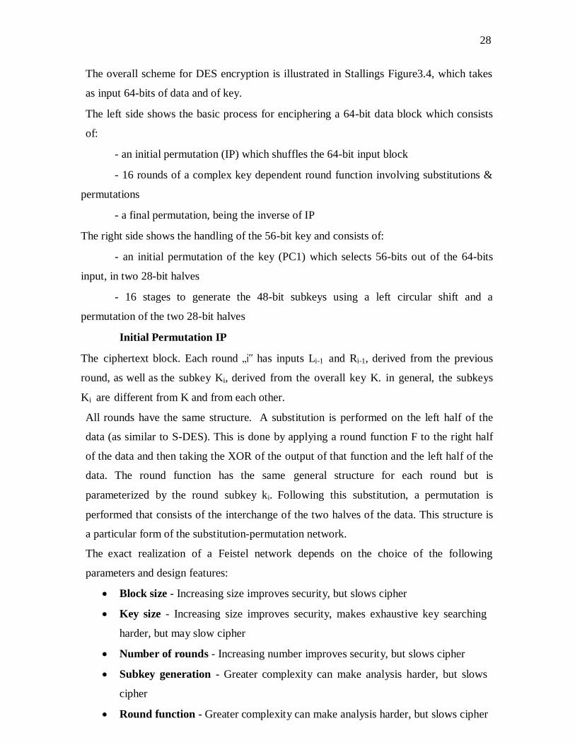
The overall scheme for DES encryption is illustrated in Stallings Figure3.4, which takes
as input 64-bits of data and of key.
The left side shows the basic process for enciphering a 64-bit data block which consists
of:
- an initial permutation (IP) which shuffles the 64-bit input block
- 16 rounds of a complex key dependent round function involving substitutions &
permutations
- a final permutation, being the inverse of IP
The right side shows the handling of the 56-bit key and consists of:
- an initial permutation of the key (PC1) which selects 56-bits out of the 64-bits
input, in two 28-bit halves
- 16 stages to generate the 48-bit subkeys using a left circular shift and a
permutation of the two 28-bit halves
Initial Permutation IP
The ciphertext block. Each round „i‟ has inputs Li-1 and Ri-1, derived from the previous
round, as well as the subkey Ki, derived from the overall key K. in general, the subkeys
Ki are different from K and from each other.
All rounds have the same structure. A substitution is performed on the left half of the
data (as similar to S-DES). This is done by applying a round function F to the right half
of the data and then taking the XOR of the output of that function and the left half of the
data. The round function has the same general structure for each round but is
parameterized by the round subkey ki. Following this substitution, a permutation is
performed that consists of the interchange of the two halves of the data. This structure is
a particular form of the substitution-permutation network.
The exact realization of a Feistel network depends on the choice of the following
parameters and design features:
Block size - Increasing size improves security, but slows cipher
Key size - Increasing size improves security, makes exhaustive key searching
harder, but may slow cipher
Number of rounds - Increasing number improves security, but slows cipher
Subkey generation - Greater complexity can make analysis harder, but slows
cipher
Round function - Greater complexity can make analysis harder, but slows cipher

29
Fast software en/decryption & ease of analysis - are more recent concerns

29
Fig: Feistel encryption and decryption
The process of decryption is essentially the same as the encryption process. The rule is as
follows: use the cipher text as input to the algorithm, but use the subkey ki in reverse
order. i.e., kn in the first round, kn-1 in second round and so on. For clarity, we use the
notation LEi and REi for data traveling through the decryption algorithm. The diagram
below indicates that, at each round, the intermediate value of the decryption process is
same (equal) to the corresponding value of the encryption process with two halves of the
value swapped.
i.e., REi || LEi (or) equivalently RD16-i || LD16-i

32
After the last iteration of the encryption process, the two halves of the output are
swapped, so that the cipher text is RE16 || LE16. The output of that round is the cipher text.
Now take the cipher text and use it as input to the same algorithm. The input to the first
round is RE16 || LE16, which is equal to the 32-bit swap of the output of the sixteenth
round of the encryption process.
Now we will see how the output of the first round of the decryption process is equal to a
32-bit swap of the input to the sixteenth round of the encryption process. First consider
the encryption process,
LE16 = RE15
RE16 = LE15 F (RE15, K16)
On the decryption side,
LD1 =RD0 = LE16 =RE15
RD1 = LD0 F (RD0, K16)
= RE16 F (RE15, K16)
= [LE15 F (RE15, K16)] F (RE15, K16)
= LE15
Therefore, LD1 = RE15
RD1 = LE15
In general, for the ith
iteration of the encryption algorithm,
LEi = REi-1
REi = LEi-1 F (REi-1, Ki)
Finally, the output of the last round of the decryption process is RE0 || LE0. A 32-bit swap
recovers the original plaintext.
PRINCIPLES OF PUBLIC KEY CRYPTOGRAPHY
The concept of public key cryptography evolved from an attempt to attack two of
the most difficult problems associated with symmetric encryption.
Key distribution under symmetric key encryption requires either (1) that two
communicants already share a key, which someone has been distributed to them
or (2) the use of a key distribution center.
Digital signatures.
Public key cryptosystems
Public key algorithms rely on one key for encryption and a different but related
key for decryption. These algorithms have the following important characteristics:
33
It is computationally infeasible to determine the decryption key given only the
knowledge of the cryptographic algorithm and the encryption key.
In addition, some algorithms, such as RSA, also exhibit the following characteristic:
Either of the two related keys can be used for encryption, with the other used for
decryption.
The essential steps are the following:
Each user generates a pair of keys to be used for encryption and decryption of
messages.
Each user places one of the two keys in a public register or other accessible file.
This is the public key. The companion key is kept private.
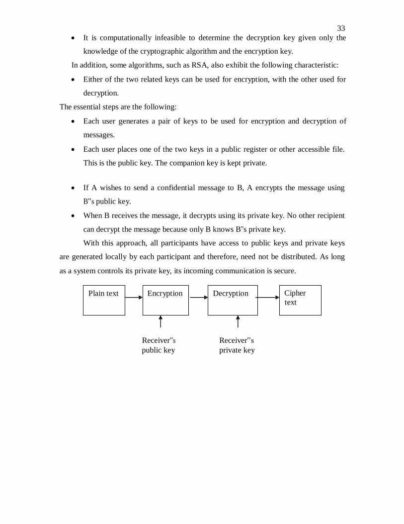
If A wishes to send a confidential message to B, A encrypts the message using
B‟s public key.
When B receives the message, it decrypts using its private key. No other recipient
can decrypt the message because only B knows B‟s private key.
With this approach, all participants have access to public keys and private keys
are generated locally by each participant and therefore, need not be distributed. As long
as a system controls its private key, its incoming communication is secure.
Plain text Encryption Decryption Cipher
text
Receiver‟s
public key
Receiver‟s
private key

33
Fig: encryption
Let the plaintext be X=[X1, X2, X3, …,Xm] where m is the number of letters in some
finite alphabets. Suppose A wishes to send a message to B. B generates a pair of keys: a
public key KUb and a private key KRb. KRb is known only to B, whereas KUb is publicly
available and therefore accessible by A.
With the message X and encryption key KUb as input, A forms the cipher text Y=[Y1,
Y2, Y3, … Yn].
i.e., Y=E KUb(X)
The receiver can decrypt it using the private key KRb.
i.e., X=D KRb()
The other approach (using sender‟s private key for encryption and sender‟s public key for
decryption) will provide authentication which is illustrated in the following diagram.
Plain text Encryption Decryption Cipher
text
Sender‟s
private key
Sender‟s
public key

34
Fig: authentication
The encrypted message serves as a digital signature.
Requirements for public key cryptography
It is computationally easy for a party B to generate a pair [KUb , KRb].
It is computationally easy for a sender A, knowing the public key and the message
to be encrypted M, to generate the corresponding ciphertext: C=EKUb(M).
It is computationally easy for the receiver B to decrypt the resulting ciphertext
using the private key to recover the original message:
M = DKRb (C) = DKRb [EKUb (M)]
It is computationally infeasible for an opponent, knowing the public key KUb, to
determine the private key KRb.
It is computationally infeasible for an opponent, knowing the public key KUb, and
a ciphertext C, to recover the original message M.
The encryption and decryption functions can be applied in either order:
M = EKUb [DKRb (M) = DKUb [EKRb (M)]
Public key cryptanalysis
Public key encryption scheme is vulnerable to a brute force attack. The counter
measure is to use large keys.
RSA Algorithm
It was developed by Rivest, Shamir and Adleman. This algorithm makes use of an
expression with exponentials. Plaintext is encrypted in blocks, with each block having a
binary value less than some number n. That is, the block size must be less than or equal to
log2 (n); in practice, the block size is k-bits, where 2k
< n < 2k+1
. Encryption and
decryption are of the following form, for some plaintext block M and ciphertext block C:
C = Me
mod n
M = Cd mod
n = (Me
mod n) mod n
= (Me)
d mod n
= Med
mod n
Both the sender and receiver know the value of n. the sender knows the value of e

35
and only the receiver knows the value of d. thus, this is a public key encryption algorithm

36
with a public key of KU = {e, n} and a private key of KR = {d, n}. For this algorithm to
be satisfactory for public key encryption, the following requirements must be met:
It is possible to find values of e, d, n such that Med =
M mod n for all M<n.
It is relatively easy to calculate Me
and Cd
for all values of M<n.
It is infeasible to determine d given e and n.
Let us focus on the first requirement. We need to find the relationship of the form:
Med =
M mod n
A corollary to Euler‟s theorem fits the bill: Given two prime numbers p and q and two
integers, n and m, such that n=pq and 0<m<n, and arbitrary integer k, the following
relationship holds
mkФ(n) +1
= mk(p-1)(q-1) +1
= m mod n
where Ф(n) – Euler totient function, which is the number of positive integers less than n
and relatively prime to n.
we can achieve the desired relationship, if
ed = kФ(n)+1
This is equivalent to saying:
ed ≡ 1 mod Ф(n)
d = e-1
mod Ф(n)
That is, e and d are multiplicative inverses mod Ф(n). According to the rule of modular
arithmetic, this is true only if d (and therefore e) is relatively prime to Ф(n). Equivalently,
gcd(Ф(n), d) = 1.
The steps involved in RSA algorithm for generating the key are
Select two prime numbers, p = 17 and q = 11.
Calculate n = p*q = 17*11 = 187
Calculate Ф(n) = (p-1)(q-1) = 16*10 = 160.
Select e such that e is relatively prime to Ф(n) = 160 and less than Ф(n); we
choose e = 7.
Determine d such that ed ≡ 1 mod Ф(n) and d<160. the correct value is d = 23,
because 23*7 = 161 = 1 mod 160.
The RSA algorithm is summarized below.
Key Generation

37
Select integer e gcd((n), e) = 1; 1< e< (n) Calculate d d= e
-1mod (n)
Select p, q p ,q both prime pq Calculate n = p x q Calculate (n) = (p -l)(q - 1)
Public key KU = { e,n} Ciphertext
Decryption
Private key
KR = {d,n}
Encryption
Plaintext
88 11
KU = 7,187 Figure : Example of RSA Algorithm
KR = 23, 187
Plaintext M < n
Ciphertext C = Me
(mod n)
Decryption
Ciphertext C
Plaintext M = Cd
(mod n)
Encryption
Security of RSA
There are three approaches to attack the RSA:
brute force key search (infeasible given size of numbers)
mathematical attacks (based on difficulty of computing ø(N), by factoring
modulus N)
timing attacks (on running time of decryption)
Factoring Problem
Mathematical approach takes 3 forms:

38
Factor n = p*q, hence find Ф(n) and then d.
Determine Ф(n)directly without determining p and q and find d.
Find d directly, without first determination Ф(n).
Timing attacks
It has been proved that the opponent can determine a private key by keeping track
of how long a computer takes to decipher messages. Although the timing attack is a
serious threat, there are simple countermeasures that can be used:
Constant exponentiation time – ensures that all exponentiations take the same
amount of time before returning a result.
Random delay – better performance could be achieved by adding a random delay
to the exponentiation algorithm to confuse the timing attack
Blinding – multiply the ciphertext by a random number before performing
exponentiation.
KEY MANAGEMENT
• Public-key encryption helps address key distribution problems
• Have two aspects:
o Distribution of public keys
o Use of public-key encryption to distribute secret keys
Distribution of Public Keys
Distribution of Public Keys can be done in one of the four ways:
Public announcement
Publicly available directory
Public-key authority
Public-key certificates
Public Announcement
• Users distribute public keys to recipients or broadcast to community at large
o eg. Append PGP keys to email messages or post to news groups or email list
• Major weakness is forgery

39
o Anyone can create a key claiming to be someone else and broadcast it
o Until forgery is discovered can masquerade as claimed user
Publicly Available Directory
• Can obtain greater security by registering keys with a public directory
• Directory must be trusted with properties:
o Contains {name, public-key} entries
o Participants register securely with directory
o Participants can replace key at any time
o Directory is periodically published
o Directory can be accessed electronically
• Still vulnerable to tampering or forgery
Public-Key Authority
• Improve security by tightening control over distribution of keys from directory
• Has properties of directory
• Requires users to know public key for the directory
• Users interact with directory to obtain any desired public key securely
o Does require real-time access to directory when keys are needed.
Public-Key Certificates
• Certificates allow key exchange without real-time access to public-key authority
• A certificate binds identity to public key
o Usually with other info such as period of validity, rights of use etc
• With all contents signed by a trusted Public-Key or Certificate Authority (CA)
• Can be verified by anyone who knows the public-key authorities public-key

40
DIFFIE-HELLMAN KEY EXCHANGE
The purpose of the algorithm is to enable two users to exchange a key securely
that can then be used for subsequent encryption of messages.
The Diffie-Hellman algorithm depends for its effectiveness on the difficulty of
computing discrete logarithms. First, we define a primitive root of a prime number p as
one whose power generate all the integers from 1 to (p-1) i.e., if „a‟ is a primitive root of
a prime number p, then the numbers
a mod p, a2
mod p, … ap-1
mod p
are distinct and consists of integers from 1 to (p-1) in some permutation. For any integer
„b‟ and a primitive root „a‟ of a prime number „p‟, we can find a unique exponent „i‟ such
that
b ≡ ai
mod p where 0 ≤ i ≤ (p-1)
The exponent „i‟ is referred to as discrete logarithm. With this background, we can define
Diffie Hellman key exchange as follows:
There are publicly known numbers: a prime number „q‟ and an integer α that is primitive
root of q. suppose users A and B wish to exchange a key. User A selects a random integer
XA < q and computes YA = α XA
mod q. Similarly, user B independently selects a random
integer XB < q and computes YB = α XB
mod q. Each side keeps the X value private and
makes the Y value available publicly to the other side. User A computes the key as

41
K = (YB)XA
mod q and
User B computes the key as
K = (YA)XB
mod q
These two calculations produce identical results.
K = (YB)XA
mod q
= (α XB
mod q)XA
mod q
= (α XB
)XA
mod q
= (α XA
)XB
mod q
= (α XA
mod q)XB
mod q
= (YA)XB
mod q
The result is that two sides have exchanged a secret key.
The security of the algorithm lies in the fact that, while it is relatively easy to calculate
exponentials modulo a prime, it is very difficult to calculate discrete logarithms. For large
primes, the latter task is considered infeasible.
Fig: Diffie Hellman Key exchange
AUTHENTICATION REQUIREMENTS
In the context of communication across a network, the following attacks can be
identified:

42
Disclosure – releases of message contents to any person or process not possessing
the appropriate cryptographic key.
Traffic analysis – discovery of the pattern of traffic between parties.
Masquerade – insertion of messages into the network fraudulent source.
Content modification – changes to the content of the message, including insertion
deletion, transposition and modification.
Sequence modification – any modification to a sequence of messages between
parties, including insertion, deletion and reordering.
Timing modification – delay or replay of messages.
Source repudiation – denial of transmission of message by source.
Destination repudiation – denial of transmission of message by destination.
Measures to deal with first two attacks are in the realm of message confidentiality.
Measures to deal with 3 through 6 are regarded as message authentication. Item 7 comes
under digital signature and dealing with item 8 may require a combination of digital
signature and a protocol to counter this attack.
AUTHENTICATION FUNCTIONS
Any message authentication or digital signature mechanism can be viewed as
having fundamentally two levels. At the lower level, there may be some sort of function
that produces an authenticator: a value to be used to authenticate a message. This lower
layer function is then used as primitive in a higher-layer authentication protocol that
enables a receiver to verify the authenticity of a message.
The different types of functions that may be used to produce an authenticator are
as follows:
Message encryption – the cipher text of the entire message serves as its
authenticator.
Message authentication code (MAC) – a public function of the message and a
secret key that produces a fixed length value serves as the authenticator.
Hash function – a public function that maps a message of any length into a fixed
length hash value, which serves as the authenticator.

43
Message encryption
Message encryption by itself can provide a measure of authentication. The
analysis differs from symmetric and public key encryption schemes.
Suppose the message can be any arbitrary bit pattern. In that case, there is no way
to determine automatically, at the destination whether an incoming message is the
ciphertext of a legitimate message. One solution to this problem is to force the plaintext
to have some structure that is easily recognized but that cannot be replicated without
recourse to the encryption function. We could, for example, append an error detecting

44
code, also known as Frame Check Sequence (FCS) or checksum to each message before
encryption
„A‟ prepares a plaintext message M and then provides this as input to a function F
that produces an FCS. The FCS is appended to M and the entire block is then encrypted.
At the destination, B decrypts the incoming block and treats the result as a message with
an appended FCS. B applies the same function F to attempt to reproduce the FCS. If the
calculated FCS is equal to the incoming FCS, then the message is considered authentic.
In the internal error control, the function F is applied to the plaintext, whereas in
external error control, F is applied to the ciphertext (encrypted message).
MESSAGE AUTHENTICATION CODE (MAC)
An alternative authentication technique involves the use of secret key to generate
a small fixed size block of data, known as cryptographic checksum or MAC that is
appended to the message. This technique assumes that two communication parties say A
and B, share a common secret key „k‟. When A has to send a message to B, it calculates
the MAC as a function of the message and the key.
MAC = CK(M) Where M – input message
C – MAC function
K – Shared secret key
45
+MAC - Message Authentication Code
The message plus MAC are transmitted to the intended recipient. The recipient
performs the same calculation on the received message, using the shared secret key, to
generate a new MAC. The received MAC is compared to the calculated MAC. If it is
equal, then the message is considered authentic.
A MAC function is similar to encryption. One difference is that MAC algorithm
need not be reversible, as it must for decryption. In general, the MAC function is a many-
to-one function.
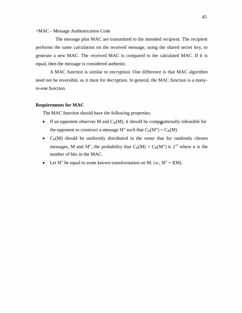
Requirements for MAC
The MAC function should have the following properties:
If an opponent observes M and CK(M), it should be computationally infeasible for
the opponent to construct a message M‟ such that CK(M‟) = CK(M)
CK(M) should be uniformly distributed in the sense that for randomly chosen
messages, M and M‟, the probability that CK(M) = CK(M‟) is 2-n
where n is the
number of bits in the MAC.
Let M‟ be equal to some known transformation on M. i.e., M‟ = f(M).

46
MAC based on DES
One of the most widely used MACs, referred to as Data Authentication Algorithm
(DAA) is based on DES.
The algorithm can be defined as using cipher block chaining (CBC) mode of
operation of DES with an initialization vector of zero. The data to be authenticated are
grouped into contiguous 64-bit blocks: D1, D2 … Dn. if necessary, the final block is
padded on the right with zeros to form a full 64-bit block. Using the DES encryption
algorithm and a secret key, a data authentication code (DAC) is calculated as follows:
O1 = EK(D1)
O2 = EK(D2 O1)
O3 = EK(D3 O2) …
ON = EK(DN ON-1)

47
HASH FUNCTIONS
A variation on the message authentication code is the one way hash function. As
with MAC, a hash function accepts a variable size message M as input and produces a
fixed-size output, referred to as hash code H(M). Unlike a MAC, a hash code does not
use a key but is a function only of the input message. The hash code is also referred to as
a message digest or hash value.
There are varieties of ways in which a hash code can be used to provide message
authentication, as follows:
a) The message plus the hash code is encrypted using symmetric encryption. This is
identical to that of internal error control strategy. Because encryption is applied to
the entire message plus the hash code, confidentiality is also provided.
b) Only the hash code is encrypted, using symmetric encryption. This reduces the
processing burden for those applications that do not require confidentiality.

48
c) Only the hash code is encrypted, using the public key encryption and using the
sender‟s private key. It provides authentication plus the digital signature.
d) If confidentiality as well as digital signature is desired, then the message plus the
public key encrypted hash code can be encrypted using a symmetric secret key.
e) This technique uses a hash function, but no encryption for message
authentication. This technique assumes that the two communicating parties share
a common secret value „S‟. The source computes the hash value over the
concatenation of M and S and appends the resulting hash value to M.
f) Confidentiality can be added to the previous approach by encrypting the entire
message plus the hash code.

49
KERBEROS
Kerberos provides a centralized authentication server whose function is to
authenticate users to servers and servers to users. Kerberos relies exclusively on
conventional encryption, making no use of public-key encryption.
The following are the requirements for Kerberos:
secure
reliable
transparent
scalable
A simple authentication dialogue
In an unprotected network environment, any client can apply to any server for
service. The obvious security risk is that of impersonation. To counter this threat, servers
must be able to confirm the identities of clients who request service. But in an open
environment, this places a substantial burden on each server.
An alternative is to use an authentication server (AS) that knows the passwords of
all users and stores these in a centralized database. In addition, the AS shares a unique
secret key with each server. The simple authentication dialogue is as follows:
1. C >> AS: IDc||Pc||IDv
2. AS >> C: Ticket
3. C >> V: IDc||Ticket
Ticket= EKv(IDc||ADc||IDv)

50
C: Client, AS: Authentication Server, V: Server, IDc : ID of the client, Pc:Password of
the client, ADc: Address of client, IDv : ID of the server, Kv: secret key shared by AS
and V, ||: concatenation.
A more secure authentication dialogue
There are two major problems associated with the previous approach:
Plaintext transmission of the password.
Each time a user has to enter the password.
To solve these problems, we introduce a scheme for avoiding plaintext passwords,
and anew server, known as ticket granting server (TGS). The hypothetical scenario is as
follows:
Once per user logon session:
1. C >> AS: IDc||IDtgs
2. AS >> C: Ekc (Tickettgs)
Once per type of service:
3. C >> TGS: IDc||IDv||Tickettgs
4. TGS >> C: ticketv
Once per service session:
5. C >> V: IDc||ticketv
Tickettgs= Ektgs(IDc||ADc||IDtgs||TS1||Lifetime1)
Ticketv= Ekv(IDc||ADc||IDv||TS2||Lifetime2)
C: Client, AS: Authentication Server, V: Server, IDc : ID of the client, Pc:Password of
the client, ADc: Address of client, IDv : ID of the server, Kv: secret key shared by AS
and V, ||: concatenation, IDtgs: ID of the TGS server, TS1, TS2: time stamps, lifetime:
lifetime of the ticket.
V4 Authentication Dialogue Message Exchange
Two additional problems remain in the more secure authentication dialogue:

51
Lifetime associated with the ticket granting ticket. If the lifetime is very short,
then the user will be repeatedly asked for a password. If the lifetime is long, then
the opponent has the greater opportunity for replay.
Requirement for the servers to authenticate themselves to users.
The actual Kerberos protocol version 4 is as follows
Kerberos version 5
Version 5 of Kerberos provides a number of improvements over version 4.
Differences between version 4 and 5
Version 5 is intended to address the limitations of version 4 in two areas:
Environmental shortcomings
o encryption system dependence
o internet protocol dependence
o message byte ordering

52
o ticket lifetime
o authentication forwarding
o inter-realm authenticaiton
Technical deficiencies
o double encryption
o PCBC encryption
o Session keys
o Password attacks
The version 5 authentication dialogue
ELECTRONIC MAIL SECURITY
PRETTY GOOD PRIVACY (PGP)

53
PGP provides the confidentiality and authentication service that can be used for
electronic mail and file storage applications. The steps involved in PGP are
Select the best available cryptographic algorithms as building blocks.
Integrate these algorithms into a general purpose application that is independent
of operating system and processor and that is based on a small set of easy-to-use
commands.
Make the package and its documentation, including the source code, freely
available via the internet, bulletin boards and commercial networks.
Enter into an agreement with a company to provide a fully compatible, low cost
commercial version of PGP.
PGP has grown explosively and is now widely used. A number of reasons can be
cited for this growth.
It is available free worldwide in versions that run on a variety of platform.
It is based on algorithms that have survived extensive public review and are
considered extremely secure.
e.g., RSA, DSS and Diffie Hellman for public key encryption
CAST-128, IDEA and 3DES for conventional encryption
SHA-1 for hash coding.
It has a wide range of applicability.
It was not developed by, nor it is controlled by, any governmental or standards
organization.
Operational description
The actual operation of PGP consists of five services: authentication, confidentiality,
compression, e-mail compatibility and segmentation.
1. Authentication
The sequence for authentication is as follows:
The sender creates the message
SHA-1 is used to generate a 160-bit hash code of the message
The hash code is encrypted with RSA using the sender‟s private key and
the result is prepended to the message

54
The receiver uses RSA with the sender‟s public key to decrypt and recover
the hash code.
The receiver generates a new hash code for the message and compares it
with the decrypted hash code. If the two match, the message is accepted as
authentic.
2. Confidentiality
Confidentiality is provided by encrypting messages to be transmitted or to be
stored locally as files. In both cases, the conventional encryption algorithm
CAST-128 may be used. The 64-bit cipher feedback (CFB) mode is used.
In PGP, each conventional key is used only once. That is, a new key is generated
as a random 128-bit number for each message. Thus although this is referred to as
a session key, it is in reality a one time key. To protect the key, it is encrypted
with the receiver‟s public key.
The sequence for confidentiality is as follows:
The sender generates a message and a random 128-bit number to be used
as a session key for this message only.
The message is encrypted using CAST-128 with the session key.
The session key is encrypted with RSA, using the receiver‟s public key
and is prepended to the message.
The receiver uses RSA with its private key to decrypt and recover the
session key.
The session key is used to decrypt the message.
Confidentiality and authentication
Here both services may be used for the same message. First, a signature is
generated for the plaintext message and prepended to the message. Then the
plaintext plus the signature is encrypted using CAST-128 and the session key is
encrypted using RSA.
3. Compression

55
As a default, PGP compresses the message after applying the signature but
before encryption. This has the benefit of saving space for both e-mail
transmission and for file storage.
The signature is generated before compression for two reasons:
It is preferable to sign an uncompressed message so that one can store
only the uncompressed message together with the signature for future
verification. If one signed a compressed document, then it would be
necessary either to store a compressed version of the message for later
verification or to recompress the message when verification is required.
Even if one were willing to generate dynamically a recompressed message
fro verification, PGP‟s compression algorithm presents a difficulty. The
algorithm is not deterministic; various implementations of the algorithm
achieve different tradeoffs in running speed versus compression ratio and
as a result, produce different compression forms.
Message encryption is applied after compression to strengthen cryptographic
security. Because the compressed message has less redundancy than the original
plaintext, cryptanalysis is more difficult. The compression algorithm used is ZIP.
4. e-mail compatibility
Many electronic mail systems only permit the use of blocks consisting of
ASCII texts. To accommodate this restriction, PGP provides the service of
converting the raw 8-bit binary stream to a stream of printable ASCII characters.
The scheme used for this purpose is radix-64 conversion. Each group of three
octets of binary data is mapped into four ASCII characters.
e.g., consider the 24-bit (3 octets) raw text sequence 00100011 01011100
10010001, we can express this input in block of 6-bits to produce 4 ASCII
characters.
001000 110101 110010 010001
I L Y R => corresponding ASCII
characters
5. Segmentation and reassembly

56
E-mail facilities often are restricted to a maximum length. E.g., many of
the facilities accessible through the internet impose a maximum length of 50,000
octets. Any message longer than that must be broken up into smaller segments,
each of which is mailed separately.
To accommodate this restriction, PGP automatically subdivides a message
that is too large into segments that are small enough to send via e-mail. The
segmentation is done after all the other processing, including the radix-64
conversion. At the receiving end, PGP must strip off all e-mail headers and
reassemble the entire original block before performing the other steps.
Cryptographic keys and key rings
Three separate requirements can be identified with respect to these keys:
A means of generating unpredictable session keys is needed.
It must allow a user to have multiple public key/private key pairs.
Each PGP entity must maintain a file of its own public/private key pairs as
well as a file of public keys of correspondents.
We now examine each of the requirements in turn.
1. Session key generation
Each session key is associated with a single message and is used only for
the purpose of encryption and decryption of that message. Random 128-bit
numbers are generated using CAST-128 itself. The input to the random number
generator consists of a 128-bit key and two 64-bit blocks that are treated as
plaintext to be encrypted. Using cipher feedback mode, the CAST-128 produces
two 64-bit cipher text blocks, which are concatenated to form the 128-bit session
key. The plaintext input to CAST-128 is itself derived from a stream of 128-bit
randomized numbers. These numbers are based on the keystroke input from the
user.
2. Key identifiers
If multiple public/private key pair are used, then how does the recipient
know which of the public keys was used to encrypt the session key? One simple

57
solution would be to transmit the public key with the message but, it is
unnecessary wasteful of space. Another solution would be to associate an
identifier with each public key that is unique at least within each user.
The solution adopted by PGP is to assign a key ID to each public key that is, with
very high probability, unique within a user ID. The key ID associated with each
public key consists of its least significant 64 bits. i.e., the key ID of public key
KUa is (KUa mod 264
).
A message consists of three components.
Message component – includes actual data to be transmitted, as well as the
filename and a timestamp that specifies the time of creation.
Signature component – includes the following
o Timestamp – time at which the signature was made.
o Message digest – hash code.
o Two octets of message digest – to enable the recipient to determine
if the correct public key was used to decrypt the message.
o Key ID of sender‟s public key – identifies the public key
Session key component – includes session key and the identifier of the
recipient public key.
3. Key rings
PGP provides a pair of data structures at each node, one to store the public/private
key pair owned by that node and one to store the public keys of the other users
known at that node. These data structures are referred to as private key ring and
public key ring.
The general structures of the private and public key rings are shown below:

58
Timestamp – the date/time when this entry was made.
Key ID – the least significant bits of the public key.
Public key – public key portion of the pair.
Private key – private key portion of the pair.
User ID – the owner of the key.
Key legitimacy field – indicates the extent to which PGP will trust that this is a valid
public key for this user.
Signature trust field – indicates the degree to which this PGP user trusts the signer to
certify public key.
Owner trust field – indicates the degree to which this public key is trusted to sign other
public key certificates.
PGP message generation
First consider message transmission and assume that the message is to be both signed
and encrypted. The sending PGP entity performs the following steps:

59
Passphrase H
Private-key ring
IDB
Public-key ring
Key ID
IDA
Message
M
E(KRa) DC
Key ID
Private
key KR
H EP ||
RNG
Public key
KU
Session
key K
EP ||
Output
Signature+ EC
message
Encrypted signature
+ message
Figure: PGP message generation
1. signing the message
PGP retrieves the sender‟s private key from the private key ring using user ID
as an index. If user ID was not provided, the first private key from the ring is
retrieved.
PGP prompts the user for the passpharse (password) to recover the
unencrypted private key.
The signature component of the message is constructed.
2. encrypting the message
PGP generates a session key and encrypts the message.
PGP retrieves the recipient‟s public key from the public key ring using user
ID as index.
The session key component of the message is constructed.
The receiving PGP entity performs the following steps:

60
passphrase H
Select
Private-key ring Public-key ring
E( KRb)
DC
Private key
KRb
Receiver‟s
key ID
Encrypted
session key
Encrypted
Sender‟s
DP key ID
Ks Encrypted
digest
Public key
KUa
DP
message +
signature
DC
Message Compare
H
Figure: PGP message reception
1. decrypting the message
PGP retrieves the receiver‟s private key from the private key ring, using the
key ID field in the session key component of the message as an index.
PGP prompts the user for the passpharse (password) to recover the
unencrypted private key.
PGP then recovers the session key and decrypts the message.
2. Authenticating the message
PGP retrieves the sender‟s public key from the public key ring, using the key
ID field in the signature key component of the message as an index.
PGP recovers the transmitted message digest.
PGP computes the message digest for the received message and compares it to
the transmitted message digest to authenticate.

61
PEM(PRIVACY ENHANCED MAIL) Introduction On the Internet, the notions of privacy and security are practically non-existent. Although
email is one of the most popular uses of the Internet, security experts have estimated that
only about one in every 100 messages is secured against interception and alteration.
Many people may think that sending an email in plain text is privacy-protected and
enhancement of privacy is not necessary. This is simply not the fact. Whether you realize
it or not, those messages you've been sending to business partners or friends over the
Internet have been sent in the clear; information you thought was enclosed in a sealed
envelope was instead sent just like a postcard.
When an email message is sent between two distant sites, it will generally transit dozens
of machines on the way. Any of these machines can read the message and/or record it for
future work.
Email Security Let‟s look at some of the assumptions many people have about the security and integrity
of email [1].
Authenticity
Many people assume that the name given as the sender of an email message identifies
who actually sent it. In fact, this depends on the honesty of the sender and the flexibility
of their mail package. For example, the Netscape Navigator mail function allows people
to enter their own description of who they are, and what their email address is. While this
will not allow them to receive mail that is not properly addressed to them, they can still
send mail.
Integrity
When you send a message via email, there is no guarantee that it will be received, or that
what is received is exactly what you sent. You have no way of knowing that your
message was not read or forwarded by third parties. This is due to the passing of
messages from machine to machine, between your email server and that of the intended
recipient.
At any point along the way, the mail server could lose the message, or the staff
supporting the server could read and/or alter it. This is obvious if you consider that a mail
message is only a file that gets passed from person to person along a delivery chain. Any
person in the chain can drop the whole file in the garbage, or copy, add, delete, or replace
documents in it. The next person in the chain doesn't know it's coming, what's in it, or
how big it should be. These people don't work for the same company, and quite possibly
aren‟t even on the same continent.
If you mis-spell the recipient's address, the mail server at their end may send the note
back to you as undeliverable. However, it may also send it to somebody else, who
happens to have the address you typed, or it may send it to the ―Postmaster‖, who
administers the system. Normally the postmaster will re-send it to the appropriate

person, but this is a manual process, which may take some time, or it may not be done at
all.
To add to the confusion, incoming and outgoing mail is stored in plain text files on a hard
disk in your mail server. These files can be altered by authorized administrators or by
anybody capable of assuming authority. While University employees do not do this on a
whim, the capability exists.
Reliability
As a sender, you have no way of knowing when a message was delivered. It could have
been delayed due to system problems at an intermediate link in the delivery chain. Also,
there is no standard way of requesting a receipt when the message is read. If you request
a return receipt, and the receiver‟s mail system does not recognize that function, it will
not send you an email note confirming delivery.
Because of the wide-spread nature of these problems, a number of competing solutions
are being developed that address the authentication and integrity issues. The general
consensus is to use some form of public-key cryptography, so that messages can be
decrypted only by the intended recipient, are unalterable, and can be verified as coming
from the sender.
Pretty Good Privacy, PGP, and Privacy-Enhanced Mail, PEM, are both ―systems‖ that
provide secrecy and non-repudiation of data that is sent over the Internet, mostly by email
(figure 1). Figure 1: PGP, PEM are external packages for message encryption, signing, etc.

Unit- III
Discrete Logarithms
the inverse problem to exponentiation is to find the discrete logarithm of a number modulo
p
that is to find x such that y = gx (mod p)
this is written as x = logg y (mod p)
if g is a primitive root then it always exists, otherwise it may not, eg.
x = log3 4 mod 13 has no answer
x = log2 3 mod 13 = 4 by trying successive powers
whilst exponentiation is relatively easy, finding discrete logarithms is generally a hard
problem
Diffie Hellman Key Exchange
first public-key type scheme proposed
by Diffie & Hellman in 1976 along with the exposition of public key concepts
note: now know that Williamson (UK CESG) secretly proposed the concept in 1970
is a practical method for public exchange of a secret key
used in a number of commercial products
a public-key distribution scheme
cannot be used to exchange an arbitrary message
rather it can establish a common key
known only to the two participants
value of key depends on the participants (and their private and public key information)
based on exponentiation in a finite (Galois) field (modulo a prime or a polynomial) - easy
security relies on the difficulty of computing discrete logarithms (similar to factoring) –
hard
all users agree on global parameters:

large prime integer or polynomial q
a being a primitive root mod q
each user (eg. A) generates their key
chooses a secret key (number): xA < q
compute their public key: yA = axA
mod q
each user makes public that key yA
shared session key for users A & B is KAB:
KAB = axA.xB
mod q
= yAxB
mod q (which B can compute)
= yBxA
mod q (which A can compute)
KAB is used as session key in private-key encryption scheme between Alice and Bob
if Alice and Bob subsequently communicate, they will have the same key as before, unless
they choose new public-keys
attacker needs an x, must solve discrete log

Diffie-Hellman Example
users Alice & Bob who wish to swap keys:
agree on prime q=353 and a=3
select random secret keys:
A chooses xA=97, B chooses xB=233
compute respective public keys:
yA=397
mod 353 = 40 (Alice)
yB=3233
mod 353 = 248 (Bob)
compute shared session key as:
KAB= yBxA
mod 353 = 24897
= 160 (Alice)
KAB= yAxB
mod 353 = 40233
= 160 (Bob)
Key Exchange Protocols
users could create random private/public D-H keys each time they communicate
users could create a known private/public D-H key and publish in a directory, then
consulted and used to securely communicate with them
both of these are vulnerable to a meet-in-the-Middle Attack
authentication of the keys is needed
Man-in-the-Middle Attack
The protocol depicted in Figure 10.8 is insecure against a man-in-the-middle attack.
Suppose Alice and Bob wish to exchange keys, and Darth is the adversary. The attack
proceeds as follows:

1. Darth prepares for the attack by generating two random private keys XD1 and XD2 and then
computing the corresponding public keys YD1 and YD2.
2. Alice transmits YA to Bob.
3. Darth intercepts YA and transmits YD1 to Bob. Darth also calculates K2 = (YA)X
D2 mod q.
4. Bob receives YD1 and calculates K1 = (YD1)X
E mod q.
5. Bob transmits XA to Alice.
6. Darth intercepts XA and transmits YD2 to Alice. Darth calculates K1 = (YB)X
D1 mod q.
7. Alice receives YD2 and calculates K2 = (YD2)X
A mod q.
ElGamal Public Key Cryptosystems:
Let p be a prime, and a and b nonzero integers (mod p) with
The problem of finding x is called the discrete logarithm problem, and is written:
Often a will be a primitive root mod p.
The discrete log behaves like the normal log in many ways:
Generally, finding the discrete log is a hard problem.
f(x) = ax (mod p) is an example of a one-way function.
One way functions are often used to construct public key cryptosystems. We saw one in
RSA, we now show an example using the DLOG problem.
Alice wants to send m to Bob. Bob chooses a large prime p and a primitive root a. We
assume 0 < m < p. Bob also chooses a secret integer a and computes b=aa (mod p).
Bob‘s Public key is: (p, a, b)
Alice does:
Chooses a secret random integer k and computes r=ak (mod p)
Computes t=bkm (mod p).
Sends (r,t) to Bob.
Bob decrypts by:
– a must be kept secret, else Eve can decrypt
)(mod pmtr a

– Eve sees (r,t): t is the product of two random numbers and is hence random.
Knowing r does not really help as Eve would need to be able to solve DLOG in
order to get k.
A different random k must be used for each message!
– If we have m1 and m2, and use the same k, then the ciphertexts will be (r,t1) and
(r,t2)
If Eve ever finds m1 then she has m2 also!!!
Hash Functions:
A variation on the message authentication code is the one way hash function. As with MAC, a hash
function accepts a variable size message M as input and produces a fixed-size output, referred to as
hash code H(M). Unlike a MAC, a hash code does not use a key but is a function only of the input
message. The hash code is also referred to as a message digest or hash value.
There are varieties of ways in which a hash code can be used to provide message authentication, as
follows:
a) The message plus the hash code is encrypted using symmetric encryption. This is identical to
that of internal error control strategy. Because encryption is applied to the entire message plus the
hash code, confidentiality is also provided.
b) Only the hash code is encrypted, using symmetric encryption. This reduces the processing
burden for those applications that do not require confidentiality.
ptmtmmtmt k mod/// 11222211
A hash value h is generated by a function H of the form h = H(M) where M is a variable-length
message and H(M) is the fixed-length hash value. The hash value is appended to the message at the
source at a time when the message is assumed orknown to be correct. The receiver
authenticates that message by recomputing the hashvalue.
Requirements for a Hash Function
1. H can be applied to a block of data of any size.
2. H produces a fixed-length output.
3. H(x) is relatively easy to compute for any given x, making both hardware and software
implementations practical.
4. For any given value h, it is computationally infeasible to find x such that H(x) =h. This is
sometimes referred to in the literature as the one-way property.
5. For any given block x, it is computationally infeasible to find y x such that H(y) = H(x). This is
sometimes referred to as weak collision resistance.
6. It is computationally infeasible to find any pair (x, y) such that H(x) = H(y). This is sometimes
referred to as strong collision resistance.
The first three properties are requirements for the practical application of a hash function to
message authentication.
The fourth property, the one-way property, states that it is easy to generate a code given a message
but virtually impossible to generate a message given a code. The fifth property guarantees that an
alternative message hashing to the same value as a given message cannot be found. This prevents
forgery when an encrypted hash code is used (Figures b and c).
The sixth property refers to how resistant the hash function is to a type of attack known as the
birthday attack, which we examine shortly.
Simple Hash Functions
All hash functions operate using the following general principles. The input (message, file, etc.) is
viewed as a sequence of n-bit blocks. The input is processed one block at a time in an iterative
fashion to produce an n-bit hash function.

One of the simplest hash functions is the bit-by-bit exclusive-OR (XOR) of every block. This can
be expressed as follows:
Ci = bi1 bi1 ... bim
where
Ci = ith bit of the hash code, 1 ≤i ≤n
m = number of n-bit blocks in the input bij = ith bit in jth block= XOR operation
Thus, the probability that a data error will result in an unchanged hash value is 2n. With more
predictably formatted data, the function is less effective. For example, in most normal text files,
the high-order bit of each octet is always zero. So if a 128-bit hash value is used, instead of an
effectiveness of 2128, the hash function on this type of data has an effectiveness of 2112.
A simple way to improve matters is to perform a one-bit circular shift, or rotation, on the hash
value after each block is processed. The procedure can be summarized as follows:
1. Initially set the n-bit hash value to zero.
2. Process each successive n-bit block of data as follows:
a. Rotate the current hash value to the left by one bit. b. XOR the block into the hash value.
SHA-1 Algorithm:
In order to get fast hash functions, we need to operate at the bit-level. SHA-1 is one such
algorithm.
Many of the popular hash functions (e.g. MD5, SHA-1) use an iterative design:
– Start with a message m of arbitrary length and break it into n-bit blocks,
m=[m1,m2,…,ml]. The last block is padded to fill out a full block size.
– Message blocks are processed via a sequence of rounds using a compression
function h‘ which combines current block and the result of the previous round
– X0 is an initial value, and Xl is the message digest.
In SHA-1, we pad according to the rule:
– Start with a message m of arbitrary length and break it into n-bit blocks.
– The last block is padded with a 1 followed by enough 0 bits to make the new
message 64 bits short of a multiple of 512 bits in length.
– Into the 64 unfilled bits of the last block, we append the 64-bit representation of the
length T of the message.

– Overall, we have blocks of 512 bits.
– The appended message becomes m=[m1,m2,…,mL].


Subregister Operations
Birthday Attacks

Suppose that a 64-bit hash code is used. One might think that this is quite secure. For example, if
an encrypted hash code C is transmitted with the corresponding unencrypted message M, then an
opponent would need to find an M' such that H(M') = H(M) to substitute another message and fool
the receiver.
On average, the opponent would have to try about 263 messages to find one that matches the hash
code of the intercepted message
However, a different sort of attack is possible, based on the birthday paradox The source, A, is
prepared to "sign" a message by appending the appropriate m-bit hash code and encrypting that
hash code with A's private key (Figure 11.5c).
1. The opponent generates 2m/2 variations on the message, all of which convey essentially
the same meaning. (fraudulent message
2. The two sets of messages are compared to find a pair of messages that produces the same hash
code. The probability of success, by the birthday paradox, is greater than 0.5. If no match is
found, additional valid and fraudulent messages are generated until a match is made.
3. The opponent offers the valid variation to A for signature. This signature can then be attached to
the fraudulent variation for transmission to the intended recipient. Because the two variations have
the same hash code, they will produce the same signature; the opponent is assured of success even
though the encryption key is not known.
Thus, if a 64-bit hash code is used, the level of effort required is only on the order of 232 .
Block Chaining Techniques
Divide a message M into fixed-size blocks M1,M2,..., MN and use a symmetric encryption system
such as DES to compute the hash code G as follows:
Ho = initial value
Hi = EMi [Hi-1 ] G = HN
This is similar to the CBC technique, but in this case there is no secret key. As with any hash code,
this scheme is subject to the birthday attack, and if the encryption algorithm is DES and only a 64-
bit hash code is produced, then the system is vulnerable.
Furthermore, another version of the birthday attack can be used even if the opponent has access to
only one message and its valid signature and cannot obtain multiple signings.
Here is the scenario; we assume that the opponent intercepts a message with a signature in the form
of an encrypted hash code and that the unencrypted hash code is m bits long:
1. Use the algorithm defined at the beginning of this subsection to calculate the unencrypted hash
code G.
2. Construct any desired message in the form Q1, Q2,..., QN2.

3. Compute for Hi = EQi [Hi-1 ]for 1 ≤i ≤(N-2).
4. Generate 2m/2 random blocks; for each block X, compute EX[HN-2.] Generate an additional
2m/2 random blocks; for each block Y, compute DY[G], where D is the decryption function
corresponding to E.
5. Based on the birthday paradox, with high probability there will be an X and Y such that EX
[HN-2 ] = DY[ G].
6. Form the message Q1, Q2,..., QN-2, X, Y. This message has the hash code G and therefore can
be used with the intercepted encrypted signature.
This form of attack is known as a meet-in-the-middle attack.
Security of Hash Functions and Macs
Just as with symmetric and public-key encryption, we can group attacks on hash functions
and MACs into two categories: brute-force attacks and cryptanalysis.
Brute-Force Attacks
The nature of brute-force attacks differs somewhat for hash functions and MACs.
Hash Functions
The strength of a hash function against brute-force attacks depends solely on the length of the hash
code produced by the algorithm. Recall from our discussion of hash functions that there are three
desirable properties:
One-way: For any given code h, it is computationally infeasible to find x such that H(x) = h.
Weak collision resistance: For any given block x, it is computationally infeasible to find y x with
H(y) = H(x).
Strong collision resistance: It is computationally infeasible to find any pair (x, y) such that H(x)
= H(y).
For a hash code of length n, the level of effort required, as we have seen is proportional
to the following:
One way 2n
Weak collision resistance 2n
Strong collision resistance 2n/2
Message Authentication Codes
A brute-force attack on a MAC is a more difficult undertaking because it requires known message-
MAC pairs.. To attack a hash code, we can proceed in the following way. Given a fixed message x
with n-bit hash code h = H(x), a brute-force method of finding a collision is to pick a random bit

string y and check if H(y) = H(x). The attacker can do this repeatedly off line. To proceed, we need
to state the desired security property of a MAC algorithm, which can be expressed as follows:
Computation resistance: Given one or more text-MAC pairs (xi, CK[xi]), it is computationally
infeasible to compute any text-MAC pair (x, CK( x)) for any new input x ≠xi.
In other words, the attacker would like to come up with the valid MAC code for a given message x.
There are two lines of attack possible: Attack the key space and attack the MAC value. We
examine each of these in turn.
To summarize, the level of effort for brute-force attack on a MAC algorithm can be expressed as
min(2k, 2n). The assessment of strength is similar to that for symmetric encryption algorithms. It
would appear reasonable to require that the key length and MAC length satisfy a relationship such
as min(k, n) ≥N, where N is perhaps in the range of 128 bits.
Cryptanalysis
As with encryption algorithms, cryptanalytic attacks on hash functions and MAC algorithms
seek to exploit some property of the algorithm to perform some attack other than an exhaustive
search.
Hash Functions
In recent years, there has been considerable effort, and some successes, in developing cryptanalytic
attacks on hash functions. To understand these, we need to look at the overall structure of a typical
secure hash function, and is the structure of most hash functions in use today, including SHA and
Whirlpool.
The hash function takes an input message and partitions it into L fixed-sized blocks of b bits each.
If necessary, the final block is padded to b bits.
The final block also includes the value of the total length of the input to the hash function.
The inclusion of the length makes the job of the opponent more difficult.
Either the opponent must find two messages of equal length that hash to the same value or two
messages of differing lengths that, together with their length values, hash to the same value.
The hash algorithm involves repeated use of a compression function, f, that takes two inputs (an n-
bit input from the previous step, called the chaining variable, and a b-bit block) and produces an n-
bit output. At the start of hashing, the chaining variable has an initial value that is specified as part
of the algorithm. The final value of the chaining variable is the hash value. Often, b > n; hence the
term compression. The hash function can be summarized as follows:

CVo = IV = initial n-bit value CVi = f(CVi-1, Yi-1) 1 ≤i ≤L H(M) = CVL
where the input to the hash function is a message M consisting of the blocks Yo, Y1,..., YL-1. The
structure can be used to produce a secure hash function to operate on a message of any length.
Message Authentication Codes
There is much more variety in the structure of MACs than in hash functions, so it is difficult to
generalize about the cryptanalysis of MACs. Further, far less work has been done on developing
such attacks.
MD5:
The MD5 message-digest algorithm is a widely used cryptographic hash function producing
a 128-bit (16-byte) hash value, typically expressed in text format as a 32 digit hexadecimal number.
MD5 has been utilized in a wide variety of cryptographic applications, and is also commonly used
to verify data integrity.
MD5 processes a variable-length message into a fixed-length output of 128 bits. The input message
is broken up into chunks of 512-bit blocks (sixteen 32-bit words); the message is padded so that its
length is divisible by 512. The padding works as follows: first a single bit, 1, is appended to the end
of the message. This is followed by as many zeros as are required to bring the length of the
message up to 64 bits fewer than a multiple of 512. The remaining bits are filled up with 64 bits
representing the length of the original message, modulo 264
.
MD5 Algorithm Structure
Implementation Steps

• Step1 Append padding bits
The input message is "padded" (extended) so that its length (in bits) equals to 448 mod 512.
Padding is always performed, even if the length of the message is already 448 mod 512.
Padding is performed as follows: a single "1" bit is appended to the message, and then "0"
bits are appended so that the length in bits of the padded message becomes congruent to 448 mod
512. At least one bit and at most 512 bits are appended.
• Step2. Append length
A 64-bit representation of the length of the message is appended to the result of step1. If the
length of the message is greater than 2^64, only the low-order 64 bits will be used.
The resulting message (after padding with bits and with b) has a length that is an exact
multiple of 512 bits. The input message will have a length that is an exact multiple of 16 (32-bit)
words.
• Step3. Initialize MD buffer
A four-word buffer (A, B, C, D) is used to compute the message digest. Each of A, B, C, D
is a 32-bit register. These registers are initialized to the following values in hexadecimal, low-order
bytes first):
word A: 01 23 45 67
word B: 89 ab cd ef
word C: fe dc ba 98
word D: 76 54 32 10
• Step4. Process message in 16-word blocks
Four functions will be defined such that each function takes an input of three 32-bit words
and produces a 32-bit word output.
F (X, Y, Z) = XY or not (X) Z
G (X, Y, Z) = XZ or Y not (Z)
H (X, Y, Z) = X xor Y xor Z
I (X, Y, Z) = Y xor (X or not (Z))
Round 1.

[abcd k s i] denote the operation a = b + ((a + F (b, c, d) + X [k] + T [i]) <<< s).
Do the following 16 operations.
[ABCD 0 7 1] [DABC 1 12 2] [CDAB 2 17 3] [BCDA 3 22 4]
[ABCD 4 7 5] [DABC 5 12 6] [CDAB 6 17 7] [BCDA 7 22 8]
[ABCD 8 7 9] [DABC 9 12 10] [CDAB 10 17 11] [BCDA 11 22 12]
[ABCD 12 7 13] [DABC 13 12 14] [CDAB 14 17 15] [BCDA 15 22 16]
Round 1.
[abcd k s i] denote the operation a = b + ((a + F (b, c, d) + X [k] + T [i]) <<< s).
Do the following 16 operations.
[ABCD 0 7 1] [DABC 1 12 2] [CDAB 2 17 3] [BCDA 3 22 4]
[ABCD 4 7 5] [DABC 5 12 6] [CDAB 6 17 7] [BCDA 7 22 8]
[ABCD 8 7 9] [DABC 9 12 10] [CDAB 10 17 11] [BCDA 11 22 12]
[ABCD 12 7 13] [DABC 13 12 14] [CDAB 14 17 15] [BCDA 15 22 16]
The main MD5 algorithm operates on a 128-bit state, divided into four 32-bit words, denoted A, B,
C, and D. These are initialized to certain fixed constants. The main algorithm then uses each 512-
bit message block in turn to modify the state. The processing of a message block consists of four
similar stages, termed rounds; each round is composed of 16 similar operations based on a non-
linear function F, modular addition, and left rotation. Figure 1 illustrates one operation within a
round. There are four possible functions F; a different one is used in each round:
denote the XOR, AND, OR and NOT operations respectively.

MD5 consists of 64 of these operations, grouped in four rounds of 16 operations. F is a nonlinear
function; one function is used in each round. Mi denotes a 32-bit block of the message input, and Ki
denotes a 32-bit constant, different for each operation. s denotes a left bit rotation by s places; s
varies for each operation. denotes addition modulo 232
.
MD5 vs. MD4
• A fourth round has been added.
• Each step has a unique additive constant.
• The function g in round 2 was changed from (XY v XZ v YZ) to (XZ v Y not(Z)).
• Each step adds in the result of the previous step.
• The order in which input words are accessed in rounds 2 and 3 is changed.
• The shift amounts in each round have been optimized. The shifts in different rounds are
distinct.
Digital Signatures:

The most important development from the work on public-key cryptography is the digital
signature. Message authentication protects two parties who exchange messages from any third
party. However, it does not protect the two parties against each other. A digital signature is
analogous to the handwritten signature, and provides a set of security capabilities that would be
difficult to implement in any other way. It must have the following properties:
• It must verify the author and the date and time of the signature
• It must to authenticate the contents at the time of the signature
• It must be verifiable by third parties,to resolve disputes
Thus, the digital signature function includes the authentication function.
Suppose you have an electronic document (e.g. a Word file). How do you sign the
document to prove to someone that it belongs to you?
You can‘t use a scanned signature at the end– this is easy to forge and use elsewhere.
Conventional signing can‘t work in the digital world.
We require a digital signature to satisfy:
1. Digital signatures can‘t be separated from the message and attached to another message.
2. Signature needs to be verified by others.
An Application for Digital Signatures
Suppose we have two countries, A and B, that have agreed not to test any nuclear bombs
(which produce seismic waves when detonated). How can A monitor B by using seismic
sensors?
1. The sensors need to be in country B, but A needs to access them. There is a conflict here.
2. Country B wants to make sure that the message sent by the seismic sensor does not contain
―other‖ data (espionage).
3. Country A, however, wants to make sure that the data has not been altered by country B.
(Assumption: the sensor itself is tamper proof).
How can we solve this problem?
Treaty Verification Example
RSA provides a solution:
1. Country A makes an RSA public/private key. (n,e) are given to B but (p,q,d) are kept
private in the tamper-proof sensor.
2. Sensor collects data x and uses d to encrypt: y=xd (mod n), and sends x and y to country B.

3. Country B takes x and y and calculates z=ye (mod n).
4. If z=x, then B can be sure that the encrypted message corresponds to x. B then forwards
(x,y) to A.
5. Country A checks that ye (mod n)=x. If so, then A is sure that x has not been modified, and
A can trust x as being authentic.
In this example, it is hard for B to forge (x,y) and hence if (x,y) verifies A can be sure that
data came unaltered from the sensor.
RSA Signatures
The treaty example is an example of RSA signatures. We now formalize it with Alice and
Bob.
Alice publishes (n,eA) and keeps private (p,q,dA)
Alice signs m by calculating y=mdA
(mod n). The pair (m,y) is the signed document.
Bob can check that Alice signed m by:
1. Downloading Alice‘s (n,eA) from a trusted third party. Guaranteeing that he gets the right
(n,eA) is another problem (we‘ll talk about this in a later lecture).
2. Calculate z=yeA
(mod n). If z=m then Bob (or anyone else) can be guaranteed that Alice
signed m.
3. Suppose Eve wants to attach Alice‘s signature to another message m1. She cannot simply
use (m1, y) since
4. Therefore, she needs y1 with y1eA
=m1 (mod n).
5. m1 looks like a ciphertext and y1 like a plaintext. In order for Eve to make a fake y1 she
needs to be able to decrypt m1 to get y1!!! She can‘t due to hardness of RSA.
6. Existential Forgery: Eve could choose y1 first and then calculate an m1 using (n,eA) via
m1=y1eA
(mod n). Now (m1, y1) will look like a valid message and signature that Alice
created since m1=y1eA
(mod n).
7. Problem with existential forgery: Eve has made an m1 that has a signature, but m1 might be
gibberish!
8. Usefulness of existential forgery depends on whether there is an underlying ―language‖
structure.
Blind RSA Signatures

Sometimes we might want Alice to sign a document without knowing its contents (e.g.
privacy concerns: purchaser does not want Bank to know what is being purchased, but
wants Bank to authorize purchase).
We can accomplish this with RSA signatures (Bob wants Alice to sign a document m):
1. Alice generates an RSA public and private key pair.
2. Bob generates a random k mod n with gcd (k,n)=1.
3. Bob computes t=keA
m (mod n), and sends t to Alice.
4. Alice signs t as following the normal RSA signature procedure by calculating s=tdA
(mod
n). Alice sends Bob s.
5. Bob computes k-1
s (mod n). This is the signed message mdA
(mod n).
Verification:
Does Alice learn anything about m from t?
Digital Signature Properties
must depend on the message signed
must use information unique to sender
to prevent both forgery and denial
must be relatively easy to produce
must be relatively easy to recognize & verify
be computationally infeasible to forge
with new message for existing digital signature
with fraudulent digital signature for given message
be practical save digital signature in storage
Direct Digital Signatures
involve only sender & receiver
assumed receiver has sender‘s public-key
digital signature made by sender signing entire message or hash with private-key
can encrypt using receivers public-key
nmmkkmkktknsk AAAAA
AA dddededmodmod 1111

important that sign first then encrypt message & signature
security depends on sender‘s private-key
Arbitrated Digital Signatures
The arbiter plays a sensitive and crucial role in this sort of scheme, and all parties must have a great
deal of trust that the arbitration mechanism is working properly.
These schemes can be implemented with either private or public-key algorithms, and the arbiter
may or may not see the actual message contents.
Authentication Protocols
used to convince parties of each others identity and to exchange session keys
may be one-way or mutual
key issues are
confidentiality – to protect session keys
timeliness – to prevent replay attacks
published protocols are often found to have flaws and need to be modified
used to convince parties of each others identity and to exchange session keys
may be one-way or mutual
key issues are
confidentiality – to protect session keys
timeliness – to prevent replay attacks
published protocols are often found to have flaws and need to be modified
Replay Attacks
where a valid signed message is copied and later resent
simple replay
repetition that can be logged
repetition that cannot be detected
backward replay without modification
countermeasures include
use of sequence numbers (generally impractical)
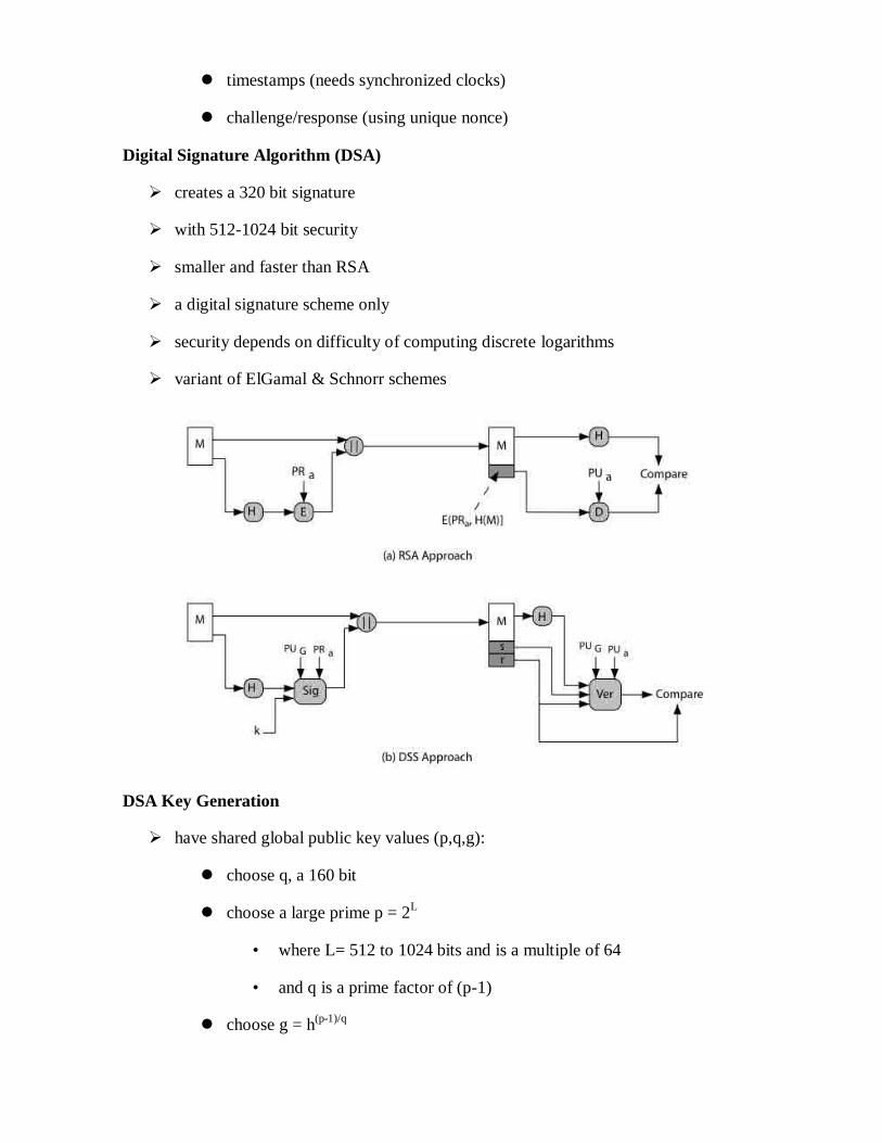
timestamps (needs synchronized clocks)
challenge/response (using unique nonce)
Digital Signature Algorithm (DSA)
creates a 320 bit signature
with 512-1024 bit security
smaller and faster than RSA
a digital signature scheme only
security depends on difficulty of computing discrete logarithms
variant of ElGamal & Schnorr schemes
DSA Key Generation
have shared global public key values (p,q,g):
choose q, a 160 bit
choose a large prime p = 2L
• where L= 512 to 1024 bits and is a multiple of 64
• and q is a prime factor of (p-1)
choose g = h(p-1)/q

• where h<p-1, h(p-1)/q
(mod p) > 1
users choose private & compute public key:
choose x<q
compute y = gx (mod p)
DSA Signature Creation
to sign a message M the sender:
generates a random signature key k, k<q
nb. k must be random, be destroyed after use, and never be reused
then computes signature pair:
r = (gk(mod p))(mod q)
s = (k-1
.H(M)+ x.r)(mod q)
sends signature (r,s) with message M
DSA Signature Verification
having received M & signature (r,s)
to verify a signature, recipient computes:
w = s-1
(mod q)
u1= (H(M).w)(mod q)
u2= (r.w)(mod q)
v = (gu1
.yu2
(mod p)) (mod q)
if v=r then signature is verified
ElGamal Signatures
We may modify the ElGamal public key procedure to become a signature scheme.
Alice wants to sign m. Alice chooses a large prime p and a primitive root a. Alice also
chooses a secret integer a and computes b=aa (mod p).
Alice‘s Public key is: (p, a, b). Security of the signature depends on the fact a is private.
Alice does:

1. Chooses a secret random integer k with gcd(k,p-1)=1, and computes r=ak (mod p)
2. Computes s=k-1
(m-ar) (mod p).
3. The signed message is the triple (m,r,s).
Bob can verify by:
1. Downloading Alice‘s public key (p, a, b).
2. Computes v1=brr
s (mod p) and v2=a
m (mod n)
3. The signature is valid if and only if v1=v2 (mod p)
Verification: We have
Therefore
This scheme is believed to be secure, as long as DLOG is hard to solve.
Don‘t: Choose a p with (p-1) the product of small primes and don‘t reuse k.
In signature schemes with appendix, where we attach the signature to the end of the
document, we increase the communication overhead.
If we have a long message m=[m1,m2,…,mN], then our signed document is
{[m1,m2,…,mN],[sigA(m1),…,sigA(mN)]}.
This doubles the overhead!
We don‘t want to do this when communication resources are precious (which is always!).
Solution: We need to shrink the message into a smaller representation and sign that.
Enter: Hash functions
Unit -IV
AUTHENTICATION SERVICES
KERBEROS
Kerberos provides a centralized authentication server whose function is to
authenticate users to servers and servers to users. Kerberos relies exclusively on
conventional encryption, making no use of public-key encryption.
The following are the requirements for Kerberos:
Secure: A network eavesdropper should not be able to obtain the necessary
information to impersonate a user. More generally, Kerberos should be strong
enough that a potential opponent does not find it to be the weak link.
Reliable: For all services that rely on Kerberos for access control, lack of
availability of the Kerberos service means lack of availability of the supported
services. Hence, Kerberos should be highly reliable and should employ a
distributed server architecture, with one system able to back up another.
Transparent: Ideally, the user should not be aware that authentication is taking

place, beyond the requirement to enter a password.
Scalable: The system should be capable of supporting large numbers of clients
and servers. This suggests a modular, distributed architecture.
To support these requirements, the overall scheme of Kerberos is that of a trusted third-
party authentication service that uses a protocol based on that proposed by Needham and
Schroeder [NEED78] It is trusted in the sense that clients and servers trust Kerberos to
mediate their mutual authentication. Assuming the Kerberos protocol is well designed,
then the authentication service is secure if the Kerberos server itself is secure.
A simple authentication dialogue
In an unprotected network environment, any client can apply to any server for
service. The obvious security risk is that of impersonation. To counter this threat, servers
must be able to confirm the identities of clients who request service. But in an open
environment, this places a substantial burden on each server.

An alternative is to use an authentication server (AS) that knows the passwords of
all users and stores these in a centralized database. In addition, the AS shares a unique
secret key with each server. The simple authentication dialogue is as follows:
C: Client,
1. C >> AS: IDc||Pc||IDv
2. AS >> C: Ticket
3. C >> V: IDc||Ticket
Ticket= EKv(IDc||ADc||IDv)
AS: Authentication Server,
V: Server, IDc : ID of the client,
Pc:Password of the client,
ADc: Address of client, IDv : ID of the server,
Kv: secret key shared by AS and V,
||: concatenation.
A more secure authentication dialogue
There are two major problems associated with the previous approach:
Plaintext transmission of the password.
Each time a user has to enter the password.
To solve these problems, we introduce a scheme for avoiding plaintext passwords,
and anew server, known as ticket granting server (TGS). The hypothetical scenario is as
follows: Once per user logon session:
1. C >> AS: IDc||IDtgs
2. AS >> C: Ekc (Tickettgs)
Once per type of service:
3. C >> TGS: IDc||IDv||Tickettgs
4. TGS >> C: ticketv
Once per service session:
5. C >> V: IDc||ticketv
Tickettgs= Ektgs(IDc||ADc||IDtgs||TS1||Lifetime1)
Ticketv= Ekv(IDc||ADc||IDv||TS2||Lifetime2)

C: Client, AS: Authentication Server, V: Server, IDc : ID of the client, Pc:Password of
the client, ADc: Address of client, IDv : ID of the server, Kv: secret key shared by AS
and V, ||: concatenation, IDtgs: ID of the TGS server, TS1, TS2: time stamps, lifetime:
lifetime of the ticket.
The new service, TGS, issues tickets to users who have been authenticated to AS. Thus,
the user first requests a ticket-granting ticket (Tickettgs) from the AS. The client module
in the user workstation saves this ticket. Each time the user requires access to a new
service, the client applies to the TGS, using the ticket to authenticate itself. The TGS then
grants a ticket for the particular service. The client saves each service-granting ticket and
uses it to authenticate its user to a server each time a particular service is requested. Let
us look at the details of this scheme:
1. The client requests a ticket-granting ticket on behalf of the user by sending its user's
ID and password to the AS, together with the TGS ID, indicating a request to use the
TGS service.
2.
The AS responds with a ticket that is encrypted with a key that is derived from the
user's password.
When this response arrives at the client, the client prompts the user for his or her
password, generates the key, and attempts to decrypt the incoming message.
If the correct password is supplied, the ticket is successfully recovered.
Because only the correct user should know the password, only the correct user can
recover the ticket. Thus, we have used the password to obtain credentials from Kerberos
without having to transmit the password in plaintext.
Now that the client has a ticket-granting ticket, access to any server can be obtained with
steps 3 and 4:
3. The client requests a service-granting ticket on behalf of the user. For this purpose, the client transmits a message to the TGS containing the user's ID, the ID of the
desired service, and the ticket-granting ticket.
4.
The TGS decrypts the incoming ticket and verifies the success of the decryption by
the presence of its ID. It checks to make sure that the lifetime has not expired. Then it
compares the user ID and network address with the incoming information to
authenticate the user. If the user is permitted access to the server V, the TGS issues a
ticket to grant access to the requested service.
The service-granting ticket has the same structure as the ticket-granting ticket. Indeed,
because the TGS is a server, we would expect that the same elements are needed to
authenticate a client to the TGS and to authenticate a client to an application server.
Again, the ticket contains a timestamp and lifetime. If the user wants access to the same
service at a later time, the client can simply use the previously acquired service-granting
ticket and need not bother the user for a password. Note that the ticket is encrypted with a
secret key (Kv) known only to the TGS and the server, preventing alteration.
Finally, with a particular service-granting ticket, the client can gain access to the
corresponding service with step 5:
5. The client requests access to a service on behalf of the user. For this purpose, the client
transmits a message to the server containing the user's ID and the service-granting
ticket. The server authenticates by using the contents of the ticket.
This new scenario satisfies the two requirements of only one password query per user
session and protection of the user password.
Kerbero V4 Authentication Dialogue Message Exchange
Two additional problems remain in the more secure authentication dialogue:
Lifetime associated with the ticket granting ticket. If the lifetime is very short,
then the user will be repeatedly asked for a password. If the lifetime is long, then
the opponent has the greater opportunity for replay.
Requirement for the servers to authenticate themselves to users.
The actual Kerberos protocol version 4 is as follows :
• a basic third-party authentication scheme
• have an Authentication Server (AS)
– users initially negotiate with AS to identify self
– AS provides a non-corruptible authentication credential (ticket granting
ticket TGT)
• have a Ticket Granting server (TGS)
– users subsequently request access to other services from TGS on basis of
users TGT

The table given below illustrates the mode of dialogue in V4
Message (1) Client requests ticket-granting ticket
IDC Tells AS identity of user from this client
IDtgs Tells AS that user requests access to TGS
TS1 Allows AS to verify that client's clock is synchronized with that of AS
Message (2) AS returns ticket-granting ticket
Kc Encryption is based on user's password, enabling AS and client to verify
password, and protecting contents of message (2)
Kc,tgs Copy of session key accessible to client created by AS to permit secure
exchange between client and TGS without requiring them to share a
permanent key
IDtgs Confirms that this ticket is for the TGS

TS2 Informs client of time this ticket was issued
Lifetime2 Informs client of the lifetime of this ticket
Tickettgs Ticket to be used by client to access TGS
(a) Authentication Service Exchange
Message (3) Client requests service-granting ticket
IDV Tells TGS that user requests access to server V
Tickettgs Assures TGS that this user has been authenticated by AS
Authenticatorc Generated by client to validate ticket
Message (4) TGS returns service-granting ticket
Kc,tgs Key shared only by C and TGS protects contents of message (4)
Kc,v Copy of session key accessible to client created by TGS to permit secure
exchange between client and server without requiring them to share a
permanent key
IDv Confirms that this ticket is for server V
TS4 Informs client of time this ticket was issued
Ticketv Ticket to be used by client to access server V
Tickettgs Reusable so that user does not have to reenter password
Ktgs Ticket is encrypted with key known only to AS and TGS, to prevent
tampering
Kc,tgs Copy of session key accessible to TGS used to decrypt authenticator,
thereby authenticating ticket
IDC Indicates the rightful owner of this ticket
ADC Prevents use of ticket from workstation other than one that initially
requested the ticket
IDtgs Assures server that it has decrypted ticket properly
TS2 Informs TGS of time this ticket was issued
Lifetime2 Prevents replay after ticket has expired
Authenticatorc Assures TGS that the ticket presenter is the same as the client for whom
the ticket was issued has very short lifetime to prevent replay
Kc,tgs Authenticator is encrypted with key known only to client and TGS, to
prevent tamperig

IDc Must match ID in ticket to authenticate ticket
ADc Must match address in ticket to authenticate ticket
TS3 Informs TGS of time this authenticator was generated
(b) Ticket-Granting Service Exchange
Message (5) Client requests service
Ticketv Assures server that this user has been authenticated by AS
Authenticatorc Generated by client to validate ticket
Message (6) Optional authentication of server to client
Kc,v Assures C that this message is from V
TS5 + 1 Assures C that this is not a replay of an old reply
Ticketv Reusable so that client does not need to request a new ticket from TGS
for each access to the same server
Kv Ticket is encrypted with key known only to TGS and server, to prevent
tampering
Kc,v Copy of session key accessible to client; used to decrypt authenticator,
thereby authenticating ticket
IDC Indicates the rightful owner of this ticket
ADc Prevents use of ticket from workstation other than one that initially
requested the ticket
IDv Assures server that it has decrypted ticket properly
TS4 Informs server of time this ticket was issued
Lifetime4 Prevents replay after ticket has expired
Authenticatorc Assures server that the ticket presenter is the same as the client for whom
the ticket was issued; has very short lifetime to prevent replay
Kc,v Authenticator is encrypted with key known only to client and server, to
prevent tampering
IDC Must match ID in ticket to authenticate ticket
ADc Must match address in ticket to authenticate ticket
TS5 Informs server of time this authenticator was generated
(c) Client/Server Authentication

Kerberos 4 Overview
Kerberos Realms and Multiple Kerberi
A full-service Kerberos environment consisting of a Kerberos server, a number of clients,
and a number of application servers requires the following:
1. The Kerberos server must have the user ID and hashed passwords of all
participating users in its database. All users are registered with the Kerberos
server.
2. The Kerberos server must share a secret key with each server. All servers are
registered with the Kerberos server.
Such an environment is referred to as a Kerberos realm.

The concept of realm can be explained as follows.
A Kerberos realm is a set of managed nodes that share the same Kerberos database. The
Kerberos database resides on the Kerberos master computer system, which should be
kept in a physically secure room.

A read-only copy of the Kerberos database might also reside on other Kerberos computer
systems.
However, all changes to the database must be made on the master computer system.
Changing or accessing the contents of a Kerberos database requires the Kerberos master
password.
A related concept is that of a Kerberos principal, which is a service or user that is known
to the Kerberos system.
Each Kerberos principal is identified by its principal name. Principal names consist of
three parts: a service or user name, an instance name, and a realm name
Networks of clients and servers under different administrative organizations typically
constitute different realms.
That is, it generally is not practical, or does not conform to administrative policy, to have
users and servers in one administrative domain registered with a Kerberos server
elsewhere.
However, users in one realm may need access to servers in other realms, and some
servers may be willing to provide service to users from other realms, provided that those
users are authenticated.
Kerberos provides a mechanism for supporting such interrealm authentication. For two
realms to support interrealm authentication, a third requirement is added:
3. The Kerberos server in each interoperating realm shares a secret key with the
server in the other realm. The two Kerberos servers are registered with each other.
The scheme requires that the Kerberos server in one realm trust the Kerberos server in the
other realm to authenticate its users. Furthermore, the participating servers in the second
realm must also be willing to trust the Kerberos server in the first realm.
Kerberos version 5
Version 5 of Kerberos provides a number of improvements over version 4.
• developed in mid 1990‘s
• provides improvements over v4
– addresses environmental shortcomings
– and technical deficiencies
• specified as Internet standard RFC 1510

Differences between version 4 and 5
Version 5 is intended to address the limitations of version 4 in two areas:
Environmental shortcomings
o encryption system dependence
o internet protocol dependence
o message byte ordering
o ticket lifetime
o authentication forwarding
o inter-realm authenticaiton
Technical deficiencies
o double encryption
o PCBC encryption
o Session keys
o Password attacks
The version 5 authentication dialogue
First, consider the authentication service exchange. Message (1) is a client request for a

ticket-granting ticket. As before, it includes the ID of the user and the TGS. The
following new elements are added:
Realm: Indicates realm of user
Options: Used to request that certain flags be set in the returned ticket
Times: Used by the client to request the following time settings in the ticket:
from: the desired start time for the requested ticket
till: the requested expiration time for the requested ticket
rtime: requested renew-till time
Nonce: A random value to be repeated in message (2) to assure that the response
is fresh and has not been replayed by an opponent
Message (2) returns a ticket-granting ticket, identifying information for the client, and a
block encrypted using the encryption key based on the user's password.
This block includes the session key to be used between the client and the TGS, times
specified in message (1), the nonce from message (1), and TGS identifying information.
The ticket itself includes the session key, identifying information for the client, the
requested time values, and flags that reflect the status of this ticket and the requested
options.
These flags introduce significant new functionality to version 5. For now, we defer a
discussion of these flags and concentrate on the overall structure of the version 5
protocol.
Let us now compare the ticket-granting service exchange for versions 4 and 5. We see
that message (3) for both versions includes an authenticator, a ticket, and the name of the
requested service.
In addition, version 5 includes requested times and options for the ticket and a nonce, all
with functions similar to those of message (1).
The authenticator itself is essentially the same as the one used in version 4.
Message (4) has the same structure as message (2), returning a ticket plus information
needed by the client, the latter encrypted with the session key now shared by the client
and the TGS.
Finally, for the client/server authentication exchange, several new features appear in
version 5. In message (5), the client may request as an option that mutual authentication
is required. The authenticator includes several new fields as follows:
Subkey: The client's choice for an encryption key to be used to protect this
specific application session. If this field is omitted, the session key from the ticket
(Kc,v) is used.

Sequence number: An optional field that specifies the starting sequence number
to be used by the server for messages sent to the client during this session.
Messages may be sequence numbered to detect replays.
If mutual authentication is required, the server responds with message (6). This message
includes the timestamp from the authenticator. Note that in version 4, the timestamp was
incremented by one. This is not necessary in version 5 because the nature of the format of
messages is such that it is not possible for an opponent to create message (6) without
knowledge of the appropriate encryption keys.
Ticket Flags
The flags field included in tickets in version 5 supports expanded functionality compared
to that available in version 4.
X.509 Certificates
Overview: • issued by a Certification Authority (CA), containing:
– version (1, 2, or 3)
– serial number (unique within CA) identifying certificate
– signature algorithm identifier
– issuer X.500 name (CA)
– period of validity (from - to dates)
– subject X.500 name (name of owner)
– subject public-key info (algorithm, parameters, key)
– issuer unique identifier (v2+)
– subject unique identifier (v2+)
– extension fields (v3)
– signature (of hash of all fields in certificate)
• notation CA<<A>> denotes certificate for A signed by CA

X.509 defines a framework for the provision of authentication services by the X.500
directory to its users. The directory may serve as a repository of public-key certificates.
Each certificate contains the public key of a user and is signed with the private key of a
trusted certification authority. In addition, X.509 defines alternative authentication
protocols based on the use of public-key certificates.
X.509 is an important standard because the certificate structure and authentication
protocols defined in X.509 are used in a variety of contexts. For example, the X.509
certificate format is used in S/MIME), IP Security and SSL/TLS and SET
X.509 is based on the use of public-key cryptography and digital signatures. The standard
does not dictate the use of a specific algorithm but recommends RSA. The digital
signature scheme is assumed to require the use of a hash function.
Certificates The heart of the X.509 scheme is the public-key certificate associated with each user.
These user certificates are assumed to be created by some trusted certification authority
(CA) and placed in the directory by the CA or by the user.
Version:
Differentiates among successive versions of the certificate format; the default is
version 1. If the Issuer Unique Identifier or Subject Unique Identifier are present, the
value must be version 2. If one or more extensions are present, the version must be
version 3.
Serial number:
An integer value, unique within the issuing CA, that is unambiguously associated
with this certificate.
Signature algorithm identifier:
The algorithm used to sign the certificate, together with any associated parameters.
Because this information is repeated in the Signature field at the end of the certificate,
this field has little, if any, utility.
Issuer name:
X.500 name of the CA that created and signed this certificate.
Period of validity:
Consists of two dates: the first and last on which the certificate is valid.

Subject name:
The name of the user to whom this certificate refers. That is, this certificate certifies
the public key of the subject who holds the corresponding private key.
Subject's public-key information:
The public key of the subject, plus an identifier of the algorithm for which this key is
to be used, together with any associated parameters.
Issuer unique identifier:
An optional bit string field used to identify uniquely the issuing CA in the event the
X.500 name has been reused for different entities. Subject unique identifier:
An optional bit string field used to identify uniquely the subject in the event the
X.500 name has been reused for different entities.
Extensions:
A set of one or more extension fields. Extensions were added in version 3 and are
discussed later in this section.
Signature: Covers all of the other fields of the certificate; it contains the hash code of the other
fields, encrypted with the CA's private key. This field includes the signature
algorithm identifier

The standard uses the following notation to define a certificate:
CA<<A>> = CA {V, SN, AI, CA, TA, A, Ap}
where
Y <<X>> = the certificate of user X issued by certification authority Y
Y {I} = the signing of I by Y. It consists of I with an encrypted
hash code appended
The CA signs the certificate with its private key. If the corresponding public key is
known to a user, then that user can verify that a certificate signed by the CA is valid.
Obtaining a User's Certificate
User certificates generated by a CA have the following characteristics:
Any user with access to the public key of the CA can verify the user public key
that was certified.
No party other than the certification authority can modify the certificate without
this being detected.
Because certificates are unforgeable, they can be placed in a directory without the need
for the directory to make special efforts to protect them.
If all users subscribe to the same CA, then there is a common trust of that CA. All user
certificates can be placed in the directory for access by all users.
If there is a large community of users, it may not be practical for all users to subscribe to
the same CA. Because it is the CA that signs certificates, each participating user must
have a copy of the CA's own public key to verify signatures. This public key must be
provided to each user in an absolutely secure (with respect to integrity and authenticity)
way so that the user has confidence in the associated certificates. Thus, with many users,
it may be more practical for there to be a number of CAs, each of which securely
provides its public key to some fraction of the users.
Now suppose that A has obtained a certificate from certification authority X1 and B has
obtained a certificate from CA X2. If A does not securely know the public key of X2, then
B's certificate, issued by X2, is useless to A.
A can read B's certificate, but A cannot verify the signature. However, if the two CAs
have securely exchanged their own public keys, the following procedure will enable A to
obtain B's public key:

1. A obtains, from the directory, the certificate of X2 signed by X1. Because A
securely knows X1's public key, A can obtain X2's public key from its certificate
and verify it by means of X1's signature on the certificate.
2. A then goes back to the directory and obtains the certificate of B signed by X2
Because A now has a trusted copy of X2's public key, A can verify the signature and securely obtain B's public key.
A has used a chain of certificates to obtain B's public key. In the notation of X.509, this
chain is expressed as
X1<<X2>> X2 <<B>>
In the same fashion, B can obtain A's public key with the reverse chain:
X2<<X1>> X1 <<A>>
This scheme need not be limited to a chain of two certificates. An arbitrarily long path of CAs can be followed to produce a chain. A chain with N elements would be expressed as
X1<<X2>> X2 <<X3>>... XN<<B>>
In this case, each pair of CAs in the chain (Xi, Xi+1) must have created certificates for
each other.
All these certificates of CAs by CAs need to appear in the directory, and the user needs to
know how they are linked to follow a path to another user's public-key certificate. X.509
suggests that CAs be arranged in a hierarchy so that navigation is straightforward.
Figure, taken from X.509, is an example of such a hierarchy. The connected circles
indicate the hierarchical relationship among the CAs; the associated boxes indicate
certificates maintained in the directory for each CA entry. The directory entry for each
CA includes two types of certificates:
Forward certificates: Certificates of X generated by other CAs
Reverse certificates: Certificates generated by X that are the certificates of other
CAs
CA Hierarchy Use
In the example given below , user A can acquire the following certificates from the
directory to establish a certification path to B:
X<<W>> W <<V>> V <<Y>> <<Z>> Z <<B>>
When A has obtained these certificates, it can unwrap the certification path in sequence
to recover a trusted copy of B's public key. Using this public key, A can send encrypted

messages to B. If A wishes to receive encrypted messages back from B, or to sign
messages sent to B, then B will require A's public key, which can be obtained from the
following certification path:
Z<<Y>> Y <<V>> V <<W>> W <<X>>X <<A>>
B can obtain this set of certificates from the directory, or A can provide them as part of
its initial message to B.
Certificate Revocation
• certificates have a period of validity
• may need to revoke before expiry, for the following reasons eg:
1. user's private key is compromised
2. user is no longer certified by this CA
3. CA's certificate is compromised
• CA‘s maintain list of revoked certificates
1. the Certificate Revocation List (CRL)

• users should check certs with CA‘s CRL
Authentication Procedures
X.509 includes three alternative authentication procedures:
• One-Way Authentication
• Two-Way Authentication
• Three-Way Authentication
• all use public-key signatures
One-Way Authentication
• 1 message ( A->B) used to establish
– the identity of A and that message is from A
– message was intended for B
– integrity & originality of message
• message must include timestamp, nonce, B's identity and is signed by A
Two-Way Authentication
• 2 messages (A->B, B->A) which also establishes in addition:
– the identity of B and that reply is from B
– that reply is intended for A
– integrity & originality of reply
• reply includes original nonce from A, also timestamp and nonce from B
Three-Way Authentication
• 3 messages (A->B, B->A, A->B) which enables above authentication without
synchronized clocks
• has reply from A back to B containing signed copy of nonce from B
• means that timestamps need not be checked or relied upon


X.509 Version 3 The X.509 version 2 format does not convey all of the information that recent design and
implementation experience has shown to be needed. [FORD95] lists the following
requirements not satisfied by version 2:
1. The Subject field is inadequate to convey the identity of a key owner to a public-
key user.
2. The Subject field is also inadequate for many applications, which typically
recognize entities by an Internet e-mail address, a URL, or some other Internet-
related identification.
3. There is a need to indicate security policy information. There is a need to limit the
damage that can result from a faulty or malicious CA by setting constraints on the
applicability of a particular certificate.
4. It is important to be able to identify different keys used by the same owner at
different times.
The certificate extensions fall into three main categories: key and policy information,
subject and issuer attributes, and certification path constraints.
Key and Policy Information
These extensions convey additional information about the subject and issuer keys, plus
indicators of certificate policy.. For example, a policy might be applicable to the
authentication of electronic data interchange (EDI) transactions for the trading of goods
within a given price range.
This area includes the following:
Authority key identifier: Identifies the public key to be used to verify the
signature on this certificate or CRL.
Subject key identifier: Identifies the public key being certified. Useful for
subject key pair updating.
Key usage: Indicates a restriction imposed as to the purposes for which, and the
policies under which, the certified public key may be used.
Private-key usage period: Indicates the period of use of the private key
corresponding to the public key.. For example, with digital signature keys, the
usage period for the signing private key is typically shorter than that for the
verifying public key.
Certificate policies: Certificates may be used in environments where multiple
policies apply.
Policy mappings: Used only in certificates for CAs issued by other CAs.

Certificate Subject and Issuer Attributes These extensions support alternative names, in alternative formats, for a certificate
subject or certificate issuer and can convey additional information about the certificate
subject, to increase a certificate user's confidence that the certificate subject is a particular
person or entity. For example, information such as postal address, position within a
corporation, or picture image may be required.
The extension fields in this area include the following:
Subject alternative name: Contains one or more alternative names, using any of
a variety of forms
Subject directory attributes: Conveys any desired X.500 directory attribute
values for the subject of this certificate.
Certification Path Constraints
These extensions allow constraint specifications to be included in certificates issued for
CAs by other CAs.
The extension fields in this area include the following:
Basic constraints: Indicates if the subject may act as a CA. If so, a certification
path length constraint may be specified.
Name constraints: Indicates a name space within which all subject names in
subsequent certificates in a certification path must be located.
Policy constraints: Specifies constraints that may require explicit certificate
policy identification or inhibit policy mapping for the remainder of the
certification path.
Public-Key Infrastructure:
RFC 2822 (Internet Security Glossary) defines public-key infrastructure
(PKI) as the set of hardware, software, people, policies, and procedures needed to
create, manage, store, distribute, and revoke digital certificates based on
asymmetric cryptography.
The IETF Public Key Infrastructure X.509 (PKIX) working group has
setup a formal (and generic) model based on X.509 that is suitable for deploying a
certificate-based architecture on the Internet.
Stallings Fig shows the interrelationship among the key elements of the
PKIX model, and lists the various management functions needed.

a) The user, called an end-entity, is not part of the PKI, but they are either users of the PKI
certificates, the subject of a certificate (an entity identified by it), or both.
b) The certificate authority (CA) is responsible for issuing, storing, and revoking
certificates—both Public Key Certificates (PKCs) and Attribute Certificates.
c) The registration authority (RA) is responsible for management activities designated by the
CA. The RA may, in fact, be a component of the CA rather than a separate component.
d) The final component of the PKIX model is a repository, system, or group of distributed
systems that provide certificates and CRLs to the end-entities.
PKIX Management functions:
registration of entity, that takes place prior to issuing the certificate
initialisation, for example generation of key–pair
certification, the issuance of the certificate
key–pair recovery, the ability to recover lost keys
key–pair update, when the certificate expires and a new key–pair and certificate have to be
generated
revocation request, when an authorised person advices the CA to include a specific
certificate into the revocation list
cross-certification, when two CAs exchange information in order to generate a cross–
certificate

ELECTRONIC MAIL SECURITY
PRETTY GOOD PRIVACY (PGP)
PGP provides the confidentiality and authentication service that can be used
for electronic mail and file storage applications. The steps involved in PGP are
Select the best available cryptographic algorithms as building blocks.
Integrate these algorithms into a general purpose application that is independent
of operating system and processor and that is based on a small set of easy-to-use
commands.
Make the package and its documentation, including the source code, freely
available via the internet, bulletin boards and commercial networks.
Enter into an agreement with a company to provide a fully compatible, low cost
commercial version of PGP.
PGP has grown explosively and is now widely used. A number of reasons can be
cited for this growth.
It is available free worldwide in versions that run on a variety of platform.
It is based on algorithms that have survived extensive public review and are
considered extremely secure.
e.g., RSA, DSS and Diffie Hellman for public key encryption
CAST-128, IDEA and 3DES for conventional encryption
SHA-1 for hash coding.
It has a wide range of applicability.
It was not developed by, nor it is controlled by, any governmental or standards
organization.
Operational description
The actual operation of PGP consists of five services: authentication, confidentiality,
compression, e-mail compatibility and segmentation.
1. Authentication
The sequence for authentication is as follows:
The sender creates the message

SHA-1 is used to generate a 160-bit hash code of the message
The hash code is encrypted with RSA using the sender‘s private key and
the result is prepended to the message
The receiver uses RSA with the sender‘s public key to decrypt and recover
the hash code.
The receiver generates a new hash code for the message and compares it
with the decrypted hash code. If the two match, the message is accepted as
authentic.
2. Confidentiality
Confidentiality is provided by encrypting messages to be transmitted or to be
stored locally as files. In both cases, the conventional encryption algorithm
CAST-128 may be used. The 64-bit cipher feedback (CFB) mode is used.
In PGP, each conventional key is used only once. That is, a new key is generated
as a random 128-bit number for each message. Thus although this is referred to as
a session key, it is in reality a one time key. To protect the key, it is encrypted
with the receiver‘s public key.
The sequence for confidentiality is as follows:
The sender generates a message and a random 128-bit number to be used
as a session key for this message only.
The message is encrypted using CAST-128 with the session key.
The session key is encrypted with RSA, using the receiver‘s public key
and is prepended to the message.
The receiver uses RSA with its private key to decrypt and recover the
session key.
The session key is used to decrypt the message.
Confidentiality and authentication
Here both services may be used for the same message. First, a signature is
generated for the plaintext message and prepended to the message. Then the

plaintext plus the signature is encrypted using CAST-128 and the session key is
encrypted using RSA.
3. Compression
As a default, PGP compresses the message after applying the signature but
before encryption. This has the benefit of saving space for both e-mail
transmission and for file storage.
The signature is generated before compression for two reasons:
It is preferable to sign an uncompressed message so that one can store
only the uncompressed message together with the signature for future
verification. If one signed a compressed document, then it would be

necessary either to store a compressed version of the message for later
verification or to recompress the message when verification is required.
Even if one were willing to generate dynamically a recompressed message
fro verification, PGP‘s compression algorithm presents a difficulty. The
algorithm is not deterministic; various implementations of the algorithm
achieve different tradeoffs in running speed versus compression ratio and
as a result, produce different compression forms.
Message encryption is applied after compression to strengthen cryptographic
security. Because the compressed message has less redundancy than the original
plaintext, cryptanalysis is more difficult. The compression algorithm used is ZIP.
4. e-mail compatibility
Many electronic mail systems only permit the use of blocks consisting of
ASCII texts. To accommodate this restriction, PGP provides the service of
converting the raw 8-bit binary stream to a stream of printable ASCII characters.
The scheme used for this purpose is radix-64 conversion. Each group of three
octets of binary data is mapped into four ASCII characters.
e.g., consider the 24-bit (3 octets) raw text sequence 00100011 01011100
10010001, we can express this input in block of 6-bits to produce 4 ASCII
characters.
001000 110101 110010 010001
I L Y R => corresponding ASCII
characters
5. Segmentation and reassembly
E-mail facilities often are restricted to a maximum length. E.g., many of
the facilities accessible through the internet impose a maximum length of 50,000
octets. Any message longer than that must be broken up into smaller segments,
each of which is mailed separately.
To accommodate this restriction, PGP automatically subdivides a message
that is too large into segments that are small enough to send via e-mail. The
segmentation is done after all the other processing, including the radix-64

conversion. At the receiving end, PGP must strip off all e-mail headers and
reassemble the entire original block before performing the other steps.
PGP Operation Summary:
Cryptographic keys and key rings
Three separate requirements can be identified with respect to these keys:
A means of generating unpredictable session keys is needed.
It must allow a user to have multiple public key/private key pairs.
Each PGP entity must maintain a file of its own public/private key pairs as
well as a file of public keys of correspondents.
We now examine each of the requirements in turn.
1. Session key generation
Each session key is associated with a single message and is used only for
the purpose of encryption and decryption of that message. Random 128-bit
numbers are generated using CAST-128 itself. The input to the random number
generator consists of a 128-bit key and two 64-bit blocks that are treated as
plaintext to be encrypted. Using cipher feedback mode, the CAST-128 produces
two 64-bit cipher text blocks, which are concatenated to form the 128-bit session
key. The plaintext input to CAST-128 is itself derived from a stream of 128-bit
randomized numbers. These numbers are based on the keystroke input from the
user.
2. Key identifiers
If multiple public/private key pair are used, then how does the recipient
know which of the public keys was used to encrypt the session key? One simple
solution would be to transmit the public key with the message but, it is
unnecessary wasteful of space. Another solution would be to associate an
identifier with each public key that is unique at least within each user.
The solution adopted by PGP is to assign a key ID to each public key that is, with
very high probability, unique within a user ID. The key ID associated with each
public key consists of its least significant 64 bits. i.e., the key ID of public key
KUa is (KUa mod 264
).
A message consists of three components.
Message component – includes actual data to be transmitted, as well as
the filename and a timestamp that specifies the time of creation.
Signature component – includes the following
o Timestamp – time at which the signature was made.
o Message digest – hash code.
o Two octets of message digest – to enable the recipient to determine
if the correct public key was used to decrypt the message.
o Key ID of sender‘s public key – identifies the public key
Session key component – includes session key and the identifier of the
recipient public key.

3. Key rings
PGP provides a pair of data structures at each node, one to store the public/private
key pair owned by that node and one to store the public keys of the other users
known at that node. These data structures are referred to as private key ring and
public key ring.
The general structures of the private and public key rings are shown below:
Timestamp – the date/time when this entry was made.
Key ID – the least significant bits of the public key.
Public key – public key portion of the pair.
Private key – private key portion of the pair.
User ID – the owner of the key.

Key legitimacy field – indicates the extent to which PGP will trust that this is a valid
public key for this user.
Signature trust field – indicates the degree to which this PGP user trusts the signer to
certify public key.
Owner trust field – indicates the degree to which this public key is trusted to sign other
public key certificates.
PGP message generation
First consider message transmission and assume that the message is to be both signed
and encrypted. The sending PGP entity performs the following steps:

Passphrase H
Private-key ring
IDB
Public-key ring
Key ID
IDA
Message
M
E(KRa) DC
Key ID
Private
key KR
H EP ||
RNG
Public key
KU
Session
key K
EP ||
Output
Signature+ EC
message
Encrypted signature
+ message
Figure: PGP message generation
1. signing the message
PGP retrieves the sender‘s private key from the private key ring using user ID
as an index. If user ID was not provided, the first private key from the ring is
retrieved.
PGP prompts the user for the passpharse (password) to recover the
unencrypted private key.
The signature component of the message is constructed.
2. encrypting the message
PGP generates a session key and encrypts the message.
PGP retrieves the recipient‘s public key from the public key ring using user
ID as index.
The session key component of the message is constructed.
The receiving PGP entity performs the following steps:

passphrase H
Select
Private-key ring Public-key ring
E( KRb)
DC
Private key
KRb
Receiver‘s
key ID
Encrypted
session key
Encrypted
Sender‘s
DP key ID
Ks Encrypted
digest
Public key
KUa
DP
message +
signature
DC
Message Compare
H
Figure: PGP message reception
1. decrypting the message
PGP retrieves the receiver‘s private key from the private key ring, using the
key ID field in the session key component of the message as an index.
PGP prompts the user for the passpharse (password) to recover the
unencrypted private key.
PGP then recovers the session key and decrypts the message.
2. Authenticating the message
PGP retrieves the sender‘s public key from the public key ring, using the key
ID field in the signature key component of the message as an index.
PGP recovers the transmitted message digest.
PGP computes the message digest for the received message and compares it to
the transmitted message digest to authenticate.

Public-Key Management
This whole business of protecting public keys from tampering is the single most difficult
problem in practical public key applications. PGP provides a structure for solving this
problem, with several suggested options that may be used.
Approaches to Public-Key Management
The essence of the problem is this: User A must build up a public-key ring containing the
public keys of other users to interoperate with them using PGP. Suppose that A's key ring
contains a public key attributed to B but that the key is, in fact, owned by C. This could
happen if, for example, A got the key from a bulletin board system (BBS) that was used
by B to post the public key but that has been compromised by C. The result is that two
threats now exist. First, C can send messages to A and forge B's signature, so that A will
accept the message as coming from B. Second, any encrypted message from A to B can
be read by C.
A number of approaches are possible for minimizing the risk that a user's public-key ring
contains false public keys. Suppose that A wishes to obtain a reliable public key for B.
The following are some approaches that could be used:
1. Physically get the key from B. B could store her public key (PUb) on a floppy disk
and hand it to A..
2. Verify a key by telephone. If A can recognize B on the phone, A could call B and
ask her to dictate the key, in radix-64 format, over the phone.
3. Obtain B's public key from a mutual trusted individual D. For this purpose, the
introducer, D, creates a signed certificate. The certificate includes B's public key,
the time of creation of the key, and a validity period for the key.
4. Obtain B's public key from a trusted certifying authority. Again, a public key
certificate is created and signed by the authority. A could then access the
authority, providing a user name and receiving a signed certificate.
For cases 3 and 4, A would already have to have a copy of the introducer's public key and
trust that this key is valid. Ultimately, it is up to A to assign a level of trust to anyone who
is to act as an introducer.
The Use of Trust
Although PGP does not include any specification for establishing certifying authorities or
for establishing trust, it does provide a convenient means of using trust, associating trust
with public keys, and exploiting trust information.

The basic structure is as follows. Each entry in the public-key ring is a public-key
certificate.
Associated with each such entry is a key legitimacy field that indicates the extent to
which PGP will trust that this is a valid public key for this user; the higher the level of
trust, the stronger is the binding of this user ID to this key. This field is computed by
PGP.
Also associated with the entry are zero or more signatures that the key ring owner has
collected that sign this certificate. In turn, each signature has associated with it a
signature trust field that indicates the degree to which this PGP user trusts the signer to
certify public keys.
The key legitimacy field is derived from the collection of signature trust fields in the
entry.
Finally, each entry defines a public key associated with a particular owner, and an owner
trust field is included that indicates the degree to which this public key is trusted to sign
other public-key certificates; this level of trust is assigned by the user.
.
The three fields mentioned in the previous paragraph are each contained in a structure
referred to as a trust flag byte.
Suppose that we are dealing with the public-key ring of user A. We can describe the
operation of the trust processing as follows:
1. When A inserts a new public key on the public-key ring, PGP must assign a value
to the trust flag that is associated with the owner of this public key. If the owner is
A, and therefore this public key also appears in the private-key ring, then a value
of ultimate trust is automatically assigned to the trust field. Otherwise, PGP asks
A for his assessment of the trust to be assigned to the owner of this key, and A
must enter the desired level. The user can specify that this owner is unknown,
untrusted, marginally trusted, or completely trusted.
2. When the new public key is entered, one or more signatures may be attached to it.
More signatures may be added later. When a signature is inserted into the entry,
PGP searches the public-key ring to see if the author of this signature is among
the known public-key owners. If so, the OWNERTRUST value for this owner is
assigned to the SIGTRUST field for this signature. If not, an unknown user value
is assigned.
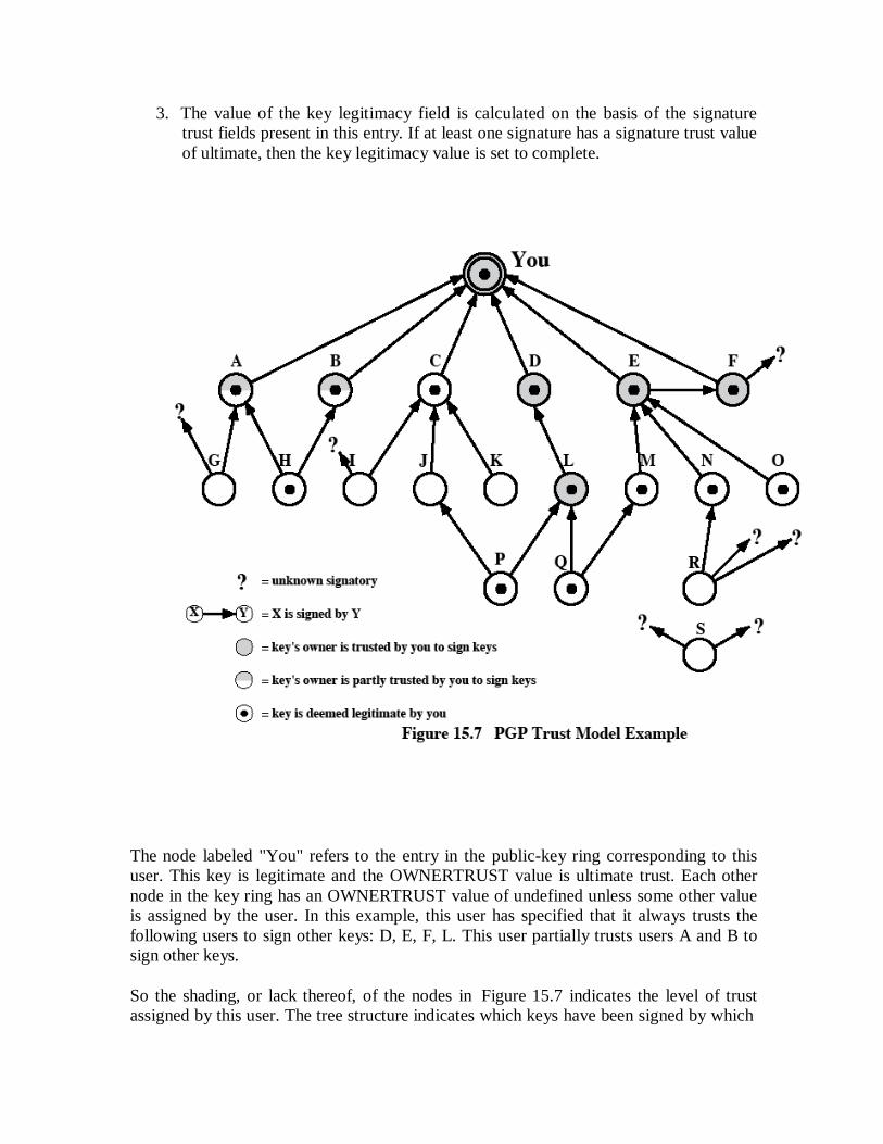
3. The value of the key legitimacy field is calculated on the basis of the signature
trust fields present in this entry. If at least one signature has a signature trust value
of ultimate, then the key legitimacy value is set to complete.
The node labeled "You" refers to the entry in the public-key ring corresponding to this
user. This key is legitimate and the OWNERTRUST value is ultimate trust. Each other
node in the key ring has an OWNERTRUST value of undefined unless some other value
is assigned by the user. In this example, this user has specified that it always trusts the
following users to sign other keys: D, E, F, L. This user partially trusts users A and B to
sign other keys.
So the shading, or lack thereof, of the nodes in Figure 15.7 indicates the level of trust
assigned by this user. The tree structure indicates which keys have been signed by which

other users. If a key is signed by a user whose key is also in this key ring, the arrow joins
the signed key to the signatory. If the key is signed by a user whose key is not present in
this key ring, the arrow joins the signed key to a question mark, indicating that the
signatory is unknown to this user.
Several points are illustrated in this Figure 15.7:
Note that all keys whose owners are fully or partially trusted by this user have
been signed by this user, with the exception of node L.
1. We assume that two partially trusted signatures are sufficient to certify a key.
Hence, the key for user H is deemed legitimate by PGP because it is signed by A
and B, both of whom are partially trusted.
2. A key may be determined to be legitimate because it is signed by one fully trusted
or two partially trusted signatories, but its user may not be trusted to sign other
keys. For example, N's key is legitimate because it is signed by E, whom this user
trusts, but N is not trusted to sign other keys because this user has not assigned N
that trust value. Therefore, although R's key is signed by N, PGP does not
consider R's key legitimate. This situation makes perfect sense. If you wish to
send a private message to some individual, it is not necessary that you trust that
individual in any respect. It is only necessary that you are sure that you have the
correct public key for that individual.
3. Figure 15.7 also shows an example of a detached "orphan" node S, with two
unknown signatures. Such a key may have been acquired from a key server. PGP
cannot assume that this key is legitimate simply because it came from a reputable
server. The user must declare the key legitimate by signing it or by telling PGP
that it is willing to trust fully one of the key's signatories.

S/MIME S/MIME (Secure/Multipurpose Internet Mail Extension) is a security enhancement to the
MIME Internet e-mail format standard, based on technology from RSA Data Security.
S/MIME is defined in a number of documents, most importantly RFCs 3369, 3370, 3850
and 3851.
Multipurpose Internet Mail Extensions
MIME is an extension to the RFC 822 framework that is intended to address some of the
problems and limitations of the use of SMTP (Simple Mail Transfer Protocol) or some
other mail transfer protocol and RFC 822 for electronic mail. Following are the
limitations of SMTP/822 scheme:
1. SMTP cannot transmit executable files or other binary objects.
2. SMTP cannot transmit text data that includes national language characters
because these are represented by 8-bit codes with values of 128 decimal or higher,
and SMTP is limited to 7-bit ASCII.
3. SMTP servers may reject mail message over a certain size.
4. SMTP gateways that translate between ASCII and the character code EBCDIC do
not use a consistent set of mappings, resulting in translation problems.
5. SMTP gateways to X.400 electronic mail networks cannot handle nontextual data
included in X.400 messages.
6. Some SMTP implementations do not adhere completely to the SMTP standards
defined in RFC 821. Common problems include:
o Deletion, addition, or reordering of carriage return and linefeed
o Truncating or wrapping lines longer than 76 characters
o Removal of trailing white space (tab and space characters)
o Padding of lines in a message to the same length
o Conversion of tab characters into multiple space characters
MIME is intended to resolve these problems in a manner that is compatible with existing
RFC 822 implementations. The specification is provided in RFCs 2045 through 2049.

Overview
The MIME specification includes the following elements:
1. Five new message header fields are defined, which may be included in an RFC
822 header. These fields provide information about the body of the message.
2. A number of content formats are defined, thus standardizing representations
that support multimedia electronic mail.
3. Transfer encodings are defined that enable the conversion of any content format
into a form that is protected from alteration by the mail system.
In this subsection, we introduce the five message header fields. The next two subsections
deal with content formats and transfer encodings.
The five header fields defined in MIME are as follows:
MIME-Version: Must have the parameter value 1.0. This field indicates that the
message conforms to RFCs 2045 and 2046.
Content-Type: Describes the data contained in the body with sufficient detail
Content-Transfer-Encoding: Indicates the type of transformation that has been
used to represent the body of the message in a way that is acceptable for mail
transport.
Content-ID: Used to identify MIME entities uniquely in multiple contexts.
Content-Description: A text description of the object with the body; this is useful
when the object is not readable (e.g., audio data).
MIME Content Types
The bulk of the MIME specification is concerned with the definition of a variety of
content types. This reflects the need to provide standardized ways of dealing with a wide
variety of information representations in a multimedia environment.
Table 15.3 lists the content types specified in RFC 2046. There are seven different major
types of content and a total of 15 subtypes

Table 15.3. MIME Content Types
(This item is displayed on page 461 in the print version)
Type Subtype Description
Text Plain Unformatted text; may be ASCII or ISO 8859.
Enriched Provides greater format flexibility.
Multipart Mixed The different parts are independent but are to be transmitted
together. They should be presented to the receiver in the order
that they appear in the mail message.
Parallel Differs from Mixed only in that no order is defined for
delivering the parts to the receiver.
Alternative The different parts are alternative versions of the same
information. They are ordered in increasing faithfulness to the
original, and the recipient's mail system should display the
"best" version to the user.
Digest Similar to Mixed, but the default type/subtype of each part is
message/rfc822.
Message rfc822 The body is itself an encapsulated message that conforms to
RFC 822.
Partial Used to allow fragmentation of large mail items, in a way that
is transparent to the recipient.
External-
body
Contains a pointer to an object that exists elsewhere.
Image jpeg The image is in JPEG format, JFIF encoding.
gif The image is in GIF format.
Video mpeg MPEG format.
Audio Basic Single-channel 8-bit ISDN mu-law encoding at a sample rate
of 8 kHz.
Application PostScript Adobe Postscript.
octet-
stream
General binary data consisting of 8-bit bytes.
For the text type of body, no special software is required to get the full meaning of the
text, aside from support of the indicated character set. The primary subtype is plain text,

which is simply a string of ASCII characters or ISO 8859 characters. The enriched
subtype allows greater formatting flexibility.
The multipart type indicates that the body contains multiple, independent parts. The
Content-Type header field includes a parameter, called boundary, that defines the
delimiter between body parts.
The multipart/digest subtype is used when each of the body parts is interpreted as an RFC
822 message with headers. This subtype enables the construction of a message whose
parts are individual messages. For example, the moderator of a group might collect e-
mail messages from participants, bundle these messages, and send them out in one
encapsulating MIME message.
The message type provides a number of important capabilities in MIME. The
message/rfc822 subtype indicates that the body is an entire message, including header
and body. Despite the name of this subtype, the encapsulated message may be not only a
simple RFC 822 message, but also any MIME message.
The message/partial subtype enables fragmentation of a large message into a number of
parts, which must be reassembled at the destination. For this subtype, three parameters
are specified in the Content-Type: Message/Partial field: an id common to all fragments
of the same message, a sequence number unique to each fragment, and the total number
of fragments.
The message/external-body subtype indicates that the actual data to be conveyed in this
message are not contained in the body. Instead, the body contains the information needed
to access the data. As with the other message types, the message/external-body subtype
has an outer header and an encapsulated message with its own header. The only
necessary field in the outer header is the Content-Type field, which identifies this as a
message/external-body subtype. The inner header is the message header for the
encapsulated message. The Content-Type field in the outer header must include an
access-type parameter, which indicates the method of access, such as FTP (file transfer
protocol).
The application type refers to other kinds of data, typically either uninterpreted binary
data or information to be processed by a mail-based application.
MIME Transfer Encodings
The other major component of the MIME specification, in addition to content type
specification, is a definition of transfer encodings for message bodies. The objective is to
provide reliable delivery across the largest range of environments.
The MIME standard defines two methods of encoding data. The Content-Transfer-
Encoding field can actually take on six values, as listed in Table 15.4. For SMTP transfer,
it is safe to use the 7bit form. The 8bit and binary forms may be usable in other mail

transport contexts. Another Content-Transfer-Encoding value is x-token, which indicates
that some other encoding scheme is used, for which a name is to be supplied. The two
actual encoding schemes defined are quoted-printable and base64.
Table 15.4. MIME Transfer Encodings
7bit The data are all represented by short lines of ASCII characters.
8bit The lines are short, but there may be non-ASCII characters (octets with the
high-order bit set).
binary Not only may non-ASCII characters be present but the lines are not
necessarily short enough for SMTP transport.
quoted-
printable
Encodes the data in such a way that if the data being encoded are mostly
ASCII text, the encoded form of the data remains largely recognizable by
humans.
base64 Encodes data by mapping 6-bit blocks of input to 8-bit blocks of output, all
of which are printable ASCII characters.
x-token A named nonstandard encoding.
The quoted-printable transfer encoding is useful when the data consists largely of octets
that correspond to printable ASCII characters. In essence, it represents nonsafe characters
by the hexadecimal representation of their code and introduces reversible (soft) line
breaks to limit message lines to 76 characters.
The base64 transfer encoding, also known as radix-64 encoding, is a common one for
encoding arbitrary binary data in such a way as to be invulnerable to the processing by
mail transport programs.
Canonical Form
An important concept in MIME and S/MIME is that of canonical form. Canonical form is
a format, appropriate to the content type, that is standardized for use between systems.
This is in contrast to native form, which is a format that may be peculiar to a particular
system.
S/MIME Functionality
In terms of general functionality, S/MIME is very similar to PGP. Both offer the ability
to sign and/or encrypt messages. In this subsection, we briefly summarize S/MIME
capability. We then look in more detail at this capability by examining message formats
and message preparation.
Functions S/MIME provides the following functions:
Enveloped data: This consists of encrypted content of any type and encrypted-
content encryption keys for one or more recipients.
Signed data: A digital signature is formed by taking the message digest of the
content to be signed and then encrypting that with the private key of the signer.
The content plus signature are then encoded using base64 encoding. A signed data
message can only be viewed by a recipient with S/MIME capability.
Clear-signed data: As with signed data, a digital signature of the content is
formed. However, in this case, only the digital signature is encoded using base64.
As a result, recipients without S/MIME capability can view the message content,
although they cannot verify the signature.
Signed and enveloped data: Signed-only and encrypted-only entities may be
nested, so that encrypted data may be signed and signed data or clear-signed data
may be encrypted.
Cryptographic Algorithms
• hash functions: SHA-1 & MD5
• digital signatures: DSS & RSA
• session key encryption: ElGamal & RSA
• message encryption: Triple-DES, RC2/40 and others
• have a procedure to decide which algorithms to use.
Table 15.6 summarizes the cryptographic algorithms used in S/MIME. S/MIME uses the
following terminology, taken from RFC 2119 to specify the requirement level:
Must: The definition is an absolute requirement of the specification. An
implementation must include this feature or function to be in conformance with
the specification.
Should: There may exist valid reasons in particular circumstances to ignore this
feature or function, but it is recommended that an implementation include the
feature or function.
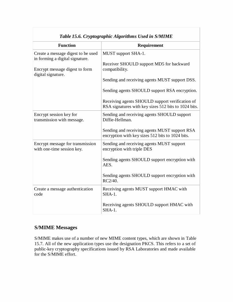
Table 15.6. Cryptographic Algorithms Used in S/MIME
Function Requirement
Create a message digest to be used
in forming a digital signature.
Encrypt message digest to form
digital signature.
MUST support SHA-1.
Receiver SHOULD support MD5 for backward
compatibility.
Sending and receiving agents MUST support DSS.
Sending agents SHOULD support RSA encryption.
Receiving agents SHOULD support verification of
RSA signatures with key sizes 512 bits to 1024 bits.
Encrypt session key for
transmission with message.
Sending and receiving agents SHOULD support
Diffie-Hellman.
Sending and receiving agents MUST support RSA
encryption with key sizes 512 bits to 1024 bits.
Encrypt message for transmission
with one-time session key.
Sending and receiving agents MUST support
encryption with triple DES
Sending agents SHOULD support encryption with
AES.
Sending agents SHOULD support encryption with
RC2/40.
Create a message authentication
code
Receiving agents MUST support HMAC with
SHA-1.
Receiving agents SHOULD support HMAC with
SHA-1.
S/MIME Messages
S/MIME makes use of a number of new MIME content types, which are shown in Table
15.7. All of the new application types use the designation PKCS. This refers to a set of
public-key cryptography specifications issued by RSA Laboratories and made available
for the S/MIME effort.

Table 15.7. S/MIME Content Types
Type Subtype smime Parameter Description
Multipart Signed A clear-signed message in two parts: one
is the message and the other is the
signature.
Application pkcs 7-
mime
signedData A signed S/MIME entity.
pkcs 7-
mime
envelopedData An encrypted S/MIME entity.
pkcs 7-
mime
degenerate
signedData
An entity containing only public- key
certificates.
pkcs 7-
mime
CompressedData A compressed S/MIME entity
pkcs 7-
signature
signedData The content type of the signature subpart
of a multipart/signed message.
We examine each of these in turn after first looking at the general procedures for
S/MIME message preparation.
SECURING A MIME ENTITY
S/MIME secures a MIME entity with a signature, encryption, or both. A MIME entity
may be an entire message (except for the RFC 822 headers), or if the MIME content type
is multipart, then a MIME entity is one or more of the subparts of the message. In all
cases, the message to be sent is converted to canonical form. In particular, for a given
type and subtype, the appropriate canonical form is used for the message content. For a
multipart message, the appropriate canonical form is used for each subpart.
The use of transfer encoding requires special attention.
i)EnvelopedData
An application/pkcs7-mime subtype is used for one of four categories of S/MIME
processing, each with a unique smime-type parameter. In all cases, the resulting entity,
referred to as an object, is represented in a form known as Basic Encoding Rules (BER),
which is defined in ITU-T Recommendation X.209. The steps for preparing an
envelopedData MIME entity are as follows:

1. Generate a pseudorandom session key for a particular symmetric encryption algorithm (RC2/40 or tripleDES).
2.
For each recipient, encrypt the session key with the recipient's public RSA key.
3.
For each recipient, prepare a block known as RecipientInfo that contains an identifier
of the recipient's public-key certificate,[3]
an identifier of the algorithm used to
encrypt the session key, and the encrypted session key.
This is an X.509 certificate, discussed later in this section.
4. Encrypt the message content with the session key.
The RecipientInfo blocks followed by the encrypted content constitute the
envelopedData. This information is then encoded into base64. To recover the encrypted
message, the recipient first strips off the base64 encoding. Then the recipient's private
key is used to recover the session key. Finally, the message content is decrypted with the
session key.
ii)SignedData
The signedData smime-type can actually be used with one or more signers. For clarity,
we confine our description to the case of a single digital signature. The steps for
preparing a signedData MIME entity are as follows:
1. Select a message digest algorithm (SHA or MD5).
2.
Compute the message digest, or hash function, of the content to be signed.
3.
Encrypt the message digest with the signer's private key.
4.
Prepare a block known as SignerInfo that contains the signer's public-key certificate,
an identifier of the message digest algorithm, an identifier of the algorithm used to
encrypt the message digest, and the encrypted message digest.
The signedData entity consists of a series of blocks, including a message digest algorithm
identifier, the message being signed, and SignerInfo. The signedData entity may also
include a set of public-key certificates sufficient to constitute a chain from a recognized
root or top-level certification authority to the signer. This information is then encoded
into base64.

To recover the signed message and verify the signature, the recipient first strips off the
base64 encoding. Then the signer's public key is used to decrypt the message digest. The
recipient independently computes the message digest and compares it to the decrypted
message digest to verify the signature.
iii)Clear Signing
Clear signing is achieved using the multipart content type with a signed subtype.
As was mentioned, this signing process does not involve transforming the
message to be signed, so that the message is sent "in the clear."
Thus, recipients with MIME capability but not S/MIME capability are able to
read the incoming message.
A multipart/signed message has two parts. The first part can be any MIME type but must
be prepared so that it will not be altered during transfer from source to destination. This
means that if the first part is not 7bit, then it needs to be encoded using base64 or quoted-
printable. Then this part is processed in the same manner as signedData, but in this case
an object with signedData format is created that has an empty message content field. This
object is a detached signature. It is then transfer encoded using base64 to become the
second part of the multipart/signed message. This second part has a MIME content type
of application and a subtype of pkcs7-signature
The protocol parameter indicates that this is a two-part clear-signed entity. The receiver
can verify the signature by taking the message digest of the first part and comparing this
to the message digest recovered from the signature in the second part.
Registration Request
Typically, an application or user will apply to a certification authority for a
public-key certificate.
The application/pkcs10 S/MIME entity is used to transfer a certification request.
The certification request includes certificationRequestInfo block, followed by an
identifier of the public-key encryption algorithm, followed by the signature of the
certificationRequestInfo block, made using the sender's private key.
The certificationRequestInfo block includes a name of the certificate subject (the
entity whose public key is to be certified) and a bit-string representation of the
user's public key.

Certificates-Only Message A message containing only certificates or a certificate revocation list (CRL) can be sent
in response to a registration request. The message is an application/pkcs7-mime
type/subtype with an smime-type parameter of degenerate. The steps involved are the
same as those for creating a signedData message, except that there is no message content
and the signerInfo field is empty.
S/MIME Certificate Processing S/MIME uses public-key certificates that conform to version 3 of X.509 The key-
management scheme used by S/MIME is in some ways a hybrid between a strict X.509
certification hierarchy and PGP's web of trust. As with the PGP model, S/MIME
managers and/or users must configure each client with a list of trusted keys and with
certificate revocation lists.
*User Agent Role
An S/MIME user has several key-management functions to perform:
Key generation: The user of some related administrative utility (e.g., one
associated with LAN management) MUST be capable of generating a key pair
from a good source of nondeterministic random input and be protected in a
secure fashion. A user agent SHOULD generate RSA key pairs with a length in
the range of 768 to 1024 bits and MUST NOT generate a length of less than 512
bits.
Registration: A user's public key must be registered with a certification authority
in order to receive an X.509 public-key certificate.
Certificate storage and retrieval: A user requires access to a local list of
certificates in order to verify incoming signatures and to encrypt outgoing
messages. Such a list could be maintained by the user or by some local
administrative entity on behalf of a number of users.
*VeriSign Certificates
There are several companies that provide certification authority (CA) services. For
example, Nortel has designed an enterprise CA solution and can provide S/MIME
support within an organization. There are a number of Internet-based CAs, including
VeriSign, GTE, and the U.S. Postal Service. Of these, the most widely used is the
VeriSign CA service, a brief description of which we now provide.
VeriSign provides a CA service that is intended to be compatible with S/MIME and a
variety of other applications. VeriSign issues X.509 certificates with the product name
VeriSign Digital ID. As of early 1998, over 35,000 commercial Web sites were using
VeriSign Server Digital IDs, and over a million consumer Digital IDs had been issued to
users of Netscape and Microsoft browsers.
The information contained in a Digital ID depends on the type of Digital ID and its
use. At a minimum, each Digital ID contains
Owner's public key
Owner's name or alias
Expiration date of the Digital ID
Serial number of the Digital ID
Name of the certification authority that issued the Digital ID
Digital signature of the certification authority that issued the Digital ID
Digital IDs can also contain other user-supplied information, including
Address
E-mail address
Basic registration information (country, zip code, age, and gender)
VeriSign provides three levels, or classes, of security for public-key certificates. A user
requests a certificate online at VeriSign's Web site or other participating Web sites. Class
1 and Class 2 requests are processed on line, and in most cases take only a few seconds to
approve. Briefly, the following procedures are used:
For Class 1 Digital IDs, VeriSign confirms the user's e-mail address by sending a
PIN and Digital ID pick-up information to the e-mail address provided in the
application.
For Class 2 Digital IDs, VeriSign verifies the information in the application
through an automated comparison with a consumer database in addition to
performing all of the checking associated with a Class 1 Digital ID. Finally,
confirmation is sent to the specified postal address alerting the user that a Digital
ID has been issued in his or her name.
For Class 3 Digital IDs, VeriSign requires a higher level of identity assurance. An
individual must prove his or her identity by providing notarized credentials or
applying in person.

Enhanced Security Services As of this writing, three enhanced security services have been proposed in an
Internet draft.:
Signed receipts: A signed receipt may be requested in a SignedData object.
Returning a signed receipt provides proof of delivery to the originator
of a message and allows the originator to demonstrate to a third party that the
recipient received the message.
Security labels: A security label may be included in the authenticated
attributes of a SignedData object. A security label is a set of security
information regarding the sensitivity of the content that is protected by
S/MIME encapsulation. The labels may be used for access control, by
indicating which users are permitted access to an object.
Secure mailing lists: When a user sends a message to multiple recipients,
a certain amount of per-recipient processing is required, including the use of
each recipient's public key. The user can be relieved of this work by
employing the services of an S/MIME Mail List Agent (MLA). An MLA
can take a single incoming message, perform the recipient-specific
encryption for each recipient, and forward the message. The originator of a
message need only send the message to the MLA, with encryption performed
using the MLA's public key.
IP Security
have a range of application specific security mechanisms
eg. S/MIME, PGP, Kerberos, SSL/HTTPS
however there are security concerns that cut across protocol layers
would like security implemented by the network for all applications
general IP Security mechanisms provides
authentication
confidentiality
key management
applicable to use over LANs, across public & private WANs, & for the Internet

Benefits of IPSec
in a firewall/router provides strong security to all traffic crossing the perimeter
in a firewall/router is resistant to bypass
is below transport layer, hence transparent to applications
can be transparent to end users
can provide security for individual users
secures routing architecture
IP Security Architecture
specification is quite complex
defined in numerous RFC‘s
incl. RFC 2401/2402/2406/2408
many others, grouped by category
mandatory in IPv6, optional in IPv4
have two security header extensions:
Authentication Header (AH)
Encapsulating Security Payload (ESP)
IPSec Documents
IPSec documents:
RFC 2401: An overview of security architecture
RFC 2402: Description of a packet encryption extension to IPv4 and IPv6
RFC 2406: Description of a packet emcryption extension to IPv4 and IPv6
RFC 2408: Specification of key managament capabilities

IPSec Services
IPSec provides security services at the IP layer by enabling a system to select required security
protocols, determine the algorithm(s) to use for the service(s), and put in place any
cryptographic keys required to provide the requested services. The security services supported
are as shown above. See Stallings Table 16.1 for the services provided by AH & ESP
respectively. For ESP, there are two cases: with and without the authentication option. Both AH
and ESP are vehicles for access control, based on the distribution of cryptographic keys and the
management of traffic flows relative to these security protocols.
Access Control
Connectionless integrity
Data origin authentication
Rejection of replayed packets
Confidentiality (encryption)
Limited traffic flow confidentiallity

Security Associations (SA)
A key concept that appears in both the authentication and confidentiality
mechanisms for IP is the security association (SA). An association is a one-way
relationship between a sender and a receiver that affords security services to the
traffic carried on it. If a peer relationship is needed, for two-way secure
exchange, then two security associations are required. Security services are
afforded to an SA for the use of AH or ESP, but not both.
A security association is uniquely identified by three parameters:
• Security Parameters Index (SPI): A bit string assigned to this SA and having
local significance only
• IP Destination Address: this is the address of the destination endpoint of the
SA
• Security Protocol Identifier: This indicates whether the association is an AH
or ESP security association.
A SA may also have a number of other parameters. In each IPSec
implementation, there is a Security Association Database that defines the
parameters associated with each SA.
SA Parameters
In each IPSec implementation, there is a nominal Security Association Database that defines
the parameters associated with each SA. A security association is normally defined by the
following parameters:
Sequence Number Counter: A 32-bit value used to generate the Sequence Number field
in AH or ESP headers(required for all implementations)..
Sequence Counter Overflow: A flag indicating whether overflow of the Sequence
Number Counter should generate an auditable event and prevent further transmission of
packets on this SA (required for all implementations).
Anti-Replay Window: Used to determine whether an inbound AH or ESP packet is a
replay, (required for all implementations).
AH Information: Authentication algorithm, keys, key lifetimes, and related parameters
being used with AH (required for AH implementations).

ESP Information: Encryption and authentication algorithm, keys, initialization values,
key lifetimes, and related parameters being used with ESP (required for ESP
implementations).
Lifetime of This Security Association: A time interval or byte count after which an SA
must be replaced with a new SA (and new SPI) or terminated, plus an indication of
which of these actions should occur (required for all implementations).
IPSec Protocol Mode: Tunnel, transport, or wildcard (required for all implementations).
These modes are discussed later in this section.
Path MTU: Any observed path maximum transmission unit (maximum size of a packet
that can be transmitted without fragmentation) and aging variables (required for all
implementations).
SA Selectors
IPSec provides the user with considerable flexibility in the way in which IPSec services are
applied to IP traffic. SAs can be combined in a number of ways to yield the desired user
configuration. The means by which IP traffic is related to specific SAs (or no SA in the case of
traffic allowed to bypass IPSec) is the nominal Security Policy Database (SPD). In its simplest
form, an SPD contains entries, each of which defines a subset of IP traffic and points to an SA
for that traffic. In more complex environments, there may be multiple entries that potentially
relate to a single SA or multiple SAs associated with a single SPD entry.
Each SPD entry is defined by a set of IP and upper-layer protocol field values, called selectors.
In effect, these selectors are used to filter outgoing traffic in order to map it into a particular
SA. Outbound processing obeys the following general sequence for each IP packet:
1. Compare the values of the appropriate fields in the packet (the selector fields) against
the SPD to find a matching SPD entry, which will point to zero or more SAs.
2. Determine the SA if any for this packet and its associated SPI.
3. Do the required IPSec processing (i.e., AH or ESP processing).
Transport and Tunnel Modes:
Both AH and ESP support two modes of use: transport and tunnel mode.
Authentication Header:
The Authentication Header provides support for data integrity and authentication
of IP packets. The data integrity feature ensures that undetected modification to a

packet‘s content in transit is not possible. The authentication feature enables an end
system or network device to authenticate the user or application and filter traffic
accordingly; it also prevents address spoofing attacks and replay attacks. Authentication
is based on the use of a message authentication code (MAC), hence the two parties must
share a secret key. AH supports MACs using HMAC-MD5-96 or HMAC-SHA-1-96.
Both of these use the HMAC algorithm , the first with the MD5 hash code and the
second with the SHA-1 hash code. In both cases, the full HMAC value is calculated but
then truncated by using the first 96bits, which is the default length for the
Authentication Data field.
provides support for data integrity & authentication of IP packets
end system/router can authenticate user/app
prevents address spoofing attacks by tracking sequence numbers
based on use of a MAC
HMAC-MD5-96 or HMAC-SHA-1-96
Parties must share a secret key
The Authentication Header fields:
• Next Header (8 bits): Identifies the type of header immediately following this
header
• Payload Length (8 bits): Length of Authentication Header in 32-bit words, minus
2.
• Reserved (16 bits): For future use
• Security Parameters Index (32 bits): Identifies a security association
• Sequence Number (32 bits): A monotonically increasing counter value
• Authentication Data (variable): A variable-length field (must be an integral
number of 32-bit words) that contains the Integrity Check Value (ICV), or
MAC,for this packet
Anti-Replay Service
A replay attack is one in which an attacker obtains a copy of an
authenticated packet and later transmits it to the intended destination. The
receipt of duplicate, authenticated IP packets may disrupt service in some way
or may have some other undesired consequence. The Sequence Number field
is designed to thwart such attacks. When a new SA is established, the sender
initializes a sequence number counter to 0. Each time that a packet is sent on
this SA, the sender increments the counter and places the value in the
Sequence Number field. Thus, the first value to be used is 1. If anti-replay is
enabled (the default), the sender must not allow the sequence number to cycle
past 232
1 back to zero. Otherwise, there would be multiple valid packets with
the same sequence number. If the limit of 232
1 is reached, the sender should
terminate this SA and negotiate a new SA with a new key.
Because IP is a connectionless, unreliable service, the protocol does not
guarantee that packets will be delivered in order and does not guarantee that
all packets will be delivered. Therefore, the IPSec authentication document
dictates that the receiver should implement a window of size W, with a default
of W = 64. The right edge of the window represents the highest sequence
number, N, so far received for a valid packet. For any packet with a sequence
number in the range from N W + 1 to N that has been correctly received (i.e.,
properly authenticated), the corresponding slot in the window is marked If the
received packet falls within the window and is new, the MAC is checked. If
the packet is authenticated, the corresponding slot in the window is marked.
1. If the received packet is to the right of the window and is new, the MAC is
checked. If the packet is authenticated, the window is advanced so that this
sequence number is the right edge of the window, and the corresponding slot in
the window is marked.
2. If the received packet is to the left of the window, or if authentication fails, the
packet is discarded; this is an auditable event.
Anti replay Mechanism

Integrity Check Value
The Authentication Data field holds a value referred to as the Integrity
Check Value. The ICV is a message authentication code or a truncated version
of a code produced by a MAC algorithm. The current specification dictates
that a compliant implementation must support
HMAC-MD5-96
HMAC-SHA-1-96
Both of these use the HMAC algorithm, the first with the MD5 hash
code and the second with the SHA-1 hash code (all of these algorithms are
described in Chapter 12). In both cases, the full HMAC value is calculated but
then truncated by using the first 96 bits, which is the default length for the
Authentication Data field.
Transport & Tunnel Modes

Figure shows the difference between end-to-end (transport) mode and
end-to-intermediate (tunnel) mode.
Transport mode provides protection primarily for upper-layer protocol
payloads, by inserting the AH after the original IP header and before the IP
payload. Typically, transport mode is used for end-to-end communication
between two hosts.
Tunnel mode provides protection to the entire IP, after the AH or ESP
fields are added to the IP packet, the entire packet plus security fields is treated
as the payload of new ―outer‖IP packet with a new outer IP header. Tunnel
mode is used when one or both ends of an SA are a security gateway, such as a
firewall or router that implements IPSec.
Encapsulating Security Payload (ESP)

provides message content confidentiality & limited traffic flow confidentiality
can optionally provide the same authentication services as AH
supports range of ciphers, modes, padding
incl. DES, Triple-DES, RC5, IDEA, CAST etc
CBC & other modes
padding needed to fill blocksize, fields, for traffic flow
Figure shows the format of an ESP packet. It contains the following fields:
• Security Parameters Index (32 bits): Identifies a security association
• Sequence Number (32 bits): A monotonically increasing counter value; this
provides an anti-replay function ,as discussed for AH
• Payload Data (variable): This is a transport-level segment (transport mode) or IP
packet (tunnel mode) that is protected by encryption
• Padding (0–255 bytes): for various reasons
• Pad Length (8 bits): Indicates the number of pad bytes immediately preceding
this field
• Next Header (8 bits): Identifies the type of data contained in the payload data
field by identifying the first header in that payload
• Authentication Data (variable): A variable-length field that contains the Integrity
Check Value computed over the ESP packet minus the Authentication Data
field.
Encryption and Authentication Algorithms
The Payload Data, Padding, Pad Length, and Next Header fields are

encrypted by the ESP service. If the algorithm used to encrypt the payload
requires cryptographic synchronization data, such as an initialization vector
(IV), then these data may be carried explicitly at the beginning of the Payload
Data field. If included, an IV is usually not encrypted, although it is often
referred to as being part of the cipher text.
A number of other algorithms have been assigned identifiers in the DOI
document and could therefore easily be used for encryption; these include
Three-key triple DES
RC5
IDEA
Three-key triple IDEA
CAST
Blowfish
Padding
The Padding field serves several purposes:
If an encryption algorithm requires the plaintext to be a multiple of some
number of bytes (e.g., the multiple of a single block for a block cipher), the
Padding field is used to expand the plaintext (consisting of the Payload Data,
Padding, Pad Length, and Next Header fields) to the required length.
The ESP format requires that the Pad Length and Next Header fields be right
aligned within a 32-bit word. Equivalently, the ciphertext must be an integer
multiple of 32 bits. The Padding field is used to assure this alignment.
Additional padding may be added to provide partial traffic flow confidentiality
by concealing the actual length of the payload.
Transport and Tunnel Modes
Figure shows two ways in which the IPSec ESP service can be used. In
the upper part of the figure, encryption (and optionally authentication) is
provided directly between two hosts. Figure 16.8b shows how tunnel mode
operation can be used to set up a virtual private network. In this example, an
organization has four private networks interconnected across the Internet.
Hosts on the internal networks use the Internet for transport of data but do not
interact with other Internet-based hosts. By terminating the tunnels at the
security gateway to each internal network, the configuration allows the hosts
to avoid implementing the security capability. The former technique is support
by a transport mode SA, while the latter technique uses a tunnel mode SA.

Transport-Mode vs. Tunnel-Mode Encryption
Transport Mode ESP
Transport mode ESP is used to encrypt and optionally authenticate the data carried
by IP (e.g., a TCP segment), as shown in Figure 16.9a. For this mode using
IPv4, the ESP header is inserted into the IP packet immediately prior to the
transport-layer header (e.g., TCP, UDP, ICMP) and an ESP trailer (Padding,
Pad Length, and Next Header fields) is placed after the IP packet; if
authentication is selected, the ESP Authentication Data field is added after the
ESP trailer. The entire transport-level segment plus the ESP trailer are
encrypted. Authentication covers all of the ciphertext plus the ESP header.
Figure 16.9. Scope of ESP Encryption and Authentication

In the context of IPv6, ESP is viewed as an end-to-end payload; that is, it is not
examined or processed by intermediate routers. Therefore, the ESP header
appears after the IPv6 base header and the hop-by-hop, routing, and fragment
extension headers. The destination options extension header could appear
before or after the ESP header, depending on the semantics desired. For IPv6,
encryption covers the entire transport-level segment plus the ESP trailer plus
the destination options extension header if it occurs after the ESP header.
Again, authentication covers the ciphertext plus the ESP header.
Transport mode operation may be summarized as follows:
1. At the source, the block of data consisting of the ESP trailer plus the entire
transport-layer segment is encrypted and the plaintext of this block is replaced
with its ciphertext to form the IP packet for transmission. Authentication is
added if this option is selected.
2. The packet is then routed to the destination. Each intermediate router needs to
examine and process the IP header plus any plaintext IP extension headers but
does not need to examine the ciphertext.
3. The destination node examines and processes the IP header plus any plaintext
IP extension headers. Then, on the basis of the SPI in the ESP header, the

destination node decrypts the remainder of the packet to recover the plaintext
transport-layer segment.
Transport mode operation provides confidentiality for any application that uses it,
thus avoiding the need to implement confidentiality in every individual
application. This mode of operation is also reasonably efficient, adding little to
the total length of the IP packet. One drawback to this mode is that it is
possible to do traffic analysis on the transmitted packets.
Tunnel Mode ESP
Tunnel mode ESP is used to encrypt an entire IP packet (Figure 16.9b).
For this mode, the ESP header is prefixed to the packet and then the packet
plus the ESP trailer is encrypted. This method can be used to counter traffic
analysis.
Because the IP header contains the destination address and possibly
source routing directives and hop-by-hop option information, it is not possible
simply to transmit the encrypted IP packet prefixed by the ESP header.
Intermediate routers would be unable to process such a packet. Therefore, it is
necessary to encapsulate the entire block (ESP header plus cipher text plus
Authentication Data, if present) with a new IP header that will contain
sufficient information for routing but not for traffic analysis.
Consider a case in which an external host wishes to communicate with a
host on an internal network protected by a firewall, and in which ESP is
implemented in the external host and the firewalls. The following steps occur
for transfer of a transport-layer segment from the external host to the internal
host:
1. The source prepares an inner IP packet with a destination address of the target
internal host. This packet is prefixed by an ESP header; then the packet and
ESP trailer are encrypted and Authentication Data may be added. The resulting
block is encapsulated with a new IP header (base header plus optional
extensions such as routing and hop-by-hop options for IPv6) whose destination
address is the firewall; this forms the outer IP packet.
2. The outer packet is routed to the destination firewall. Each intermediate router
needs to examine and process the outer IP header plus any outer IP extension
headers but does not need to examine the ciphertext.
3. The destination firewall examines and processes the outer IP header plus any
outer IP extension headers. Then, on the basis of the SPI in the ESP header, the

destination node decrypts the remainder of the packet to recover the plaintext
inner IP packet. This packet is then transmitted in the internal network.
4. The inner packet is routed through zero or more routers in the internal network
to the destination host.
Combining Security Associations
An individual SA can implement either the AH or ESP protocol but not
both. Sometimes a particular traffic flow will call for the services provided by both
AH and ESP. Further, a particular traffic flow may require IPSec services between
hosts and ,for that same flow, separate services between security gateways, such as
firewalls. In all of these cases, multiple SAs must be employed for the same traffic
flow to achieve the desired IPSec services. The term security association bundle
refers to a sequence of SAs through which traffic must be processed to provide a
desired set of IPSec services. The SAs in a bundle may terminate at different
endpoints or at the same endpoints.
Security associations may be combined into bundles in two ways:
• Transport adjacency: more than one security protocol on same IP packet, without
invoking tunneling
• Iterated tunneling: application of multiple layers of security protocols effected
through IP tunneling
One interesting issue is the order in which authentication and encryption may be
applied between a given pair of endpoints.

The IPSec Architecture document lists four examples of combinations of SAs that
must be supported by compliant IPSec hosts or security gateways. These are
illustrated in Stallings Figure 16.10. Note the *‘d devices implement IPSec. The
cases are:
Case 1 security is provided between end systems that implement IPSec.
Case 2 security is provided only between gateways (routers,firewalls,etc.) and no
hosts implement IPSec.
Case 3 builds on Case 2 by adding end-to-end security .The same combinations
discussed for cases 1 and 2 are allowed here.
Case 4 provides support for a remote host that uses the Internet to reach an
organization‘s firewall and then to gain access to some server or workstation
behind the firewall. Only tunnel mode is required between the remote host and the
firewall.
Key Management
handles key generation & distribution
typically need 2 pairs of keys
2 per direction for AH & ESP
manual key management
sysadmin manually configures every system
automated key management

automated system for on demand creation of keys for SA‘s in large
systems
has Oakley & ISAKMP elements
Oakley
a key exchange protocol
based on Diffie-Hellman key exchange
adds features to address weaknesses
cookies, groups (global params), nonces, DH key exchange with
authentication
can use arithmetic in prime fields or elliptic curve fields
ISAKMP
Internet Security Association and Key Management Protocol
provides framework for key management
defines procedures and packet formats to establish, negotiate, modify, & delete
SAs
independent of key exchange protocol, encryption alg, & authentication method
ISAKMP Payloads & Exchanges
it have a number of ISAKMP payload types:
Security, Proposal, Transform, Key, Identification, Certificate,
Certificate, Hash, Signature, Nonce, Notification, Delete
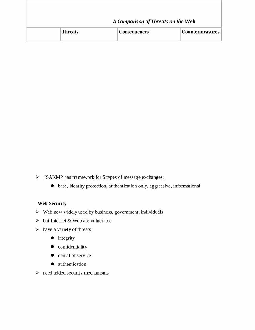
ISAKMP has framework for 5 types of message exchanges:
base, identity protection, authentication only, aggressive, informational
Web Security
Web now widely used by business, government, individuals
but Internet & Web are vulnerable
have a variety of threats
integrity
confidentiality
denial of service
authentication
need added security mechanisms
A Comparison of Threats on the Web
Threats Consequences Countermeasures

SSL (Secure Socket Layer)
transport layer security service
originally developed by Netscape
version 3 designed with public input
subsequently became Internet standard known as TLS (Transport Layer
Security)
uses TCP to provide a reliable end-to-end service
SSL has two layers of protocols
Integrity Modification of
user data
Trojan horse
browser
Modification of
memory
Modification of
message traffic in
transit
Loss of information
Compromise of
machine
Vulnerabilty to all
other threats
Cryptographic
checksums
Confidentiality Eavesdropping on
the Net
Theft of info from
server
Theft of data from
client
Info about network
configuration
Info about which
client talks to
server
Loss of information
Loss of privacy
Encryption, web
proxies
Denial of
Service
Killing of user
threads
Flooding machine
with bogus
requests
Filling up disk or
memory
Isolating machine
by DNS attacks
Disruptive
Annoying
Prevent user from
getting work done
Difficult to
prevent
Authentication Impersonation of
legitimate users
Data forgery
Misrepresentation of
user
Belief that false
information is valid
Cryptographic
techniques

SSL Protocol Stack
SSL Architecture
Two important SSL concepts are the SSL connection and the SSL session:
• Connection: A connection is a network transport that provides a suitable type of
service, such connections are transient, peer-to-peer relationships, associated
with one session
• Session: An SSL session is an association between a client and a server, created
by the Handshake Protocol. Sessions define a set of cryptographic security
parameters, which can be shared among multiple connections. Sessions are
used to avoid the expensive negotiation of new security parameters for each
connection.
A session state is defined by the following parameters (definitions taken from the
SSL specification):
Session identifier: An arbitrary byte sequence chosen by the server to identify
an active or resumable session state.
Peer certificate: An X509.v3 certificate of the peer. This element of the state
may be null.
Compression method: The algorithm used to compress data prior to encryption.
Cipher spec: Specifies the bulk data encryption algorithm (such as null, AES,
etc.) and a hash algorithm (such as MD5 or SHA-1) used for MAC calculation.
It also defines cryptographic attributes such as the hash_size.
Master secret: 48-byte secret shared between the client and server.
Is resumable: A flag indicating whether the session can be used to initiate new
connections.
A connection state is defined by the following parameters:
Server and client random: Byte sequences that are chosen by the server and
client for each connection.
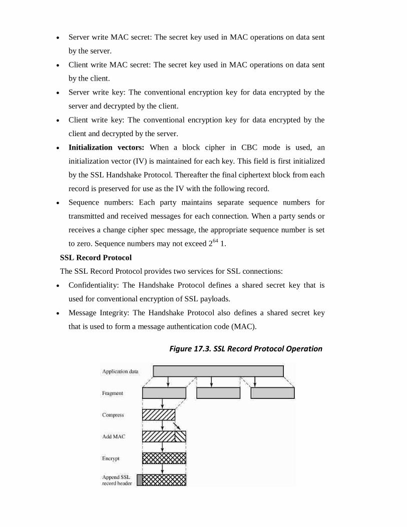
Server write MAC secret: The secret key used in MAC operations on data sent
by the server.
Client write MAC secret: The secret key used in MAC operations on data sent
by the client.
Server write key: The conventional encryption key for data encrypted by the
server and decrypted by the client.
Client write key: The conventional encryption key for data encrypted by the
client and decrypted by the server.
Initialization vectors: When a block cipher in CBC mode is used, an
initialization vector (IV) is maintained for each key. This field is first initialized
by the SSL Handshake Protocol. Thereafter the final ciphertext block from each
record is preserved for use as the IV with the following record.
Sequence numbers: Each party maintains separate sequence numbers for
transmitted and received messages for each connection. When a party sends or
receives a change cipher spec message, the appropriate sequence number is set
to zero. Sequence numbers may not exceed 264
1.
SSL Record Protocol
The SSL Record Protocol provides two services for SSL connections:
Confidentiality: The Handshake Protocol defines a shared secret key that is
used for conventional encryption of SSL payloads.
Message Integrity: The Handshake Protocol also defines a shared secret key
that is used to form a message authentication code (MAC).
Figure 17.3. SSL Record Protocol Operation

The first step is fragmentation. Each upper-layer message is fragmented into blocks of 214
bytes
(16384 bytes) or less. Next, compression is optionally applied. Compression must be lossless
and may not increase the content length by more than 1024 bytes.[2]
In SSLv3 (as well as the
current version of TLS), no compression algorithm is specified, so the default compression
algorithm is null.
SSL Change Cipher Spec Protocol
The Change Cipher Spec Protocol is one of the three SSL-specific protocols that use the SSL
Record Protocol, and it is the simplest, consisting of a single message. Its purpose is to cause
the pending state to be copied into the current state, which updates the cipher suite to be used
on this connection
SSL Alert Protocol
The Alert Protocol is used to convey SSL-related alerts to the peer entity. As with other
applications that use SSL, alert messages are compressed and encrypted, as specified by the
current state.
Each message in this protocol consists of two bytes, the first takes the value warning(1) or
fatal(2) to convey the severity of the message. The second byte contains a code that indicates
the specific alert. The first group shown are the fatal alerts, the others are warnings.
SSL Handshake Protocol
The most complex part of SSL is the Handshake Protocol. This protocol allows the server and
client to authenticate each other and to negotiate an encryption and MAC algorithm and
cryptographic keys to be used to protect data sent in an SSL record. The Handshake Protocol is
used before any application data is transmitted. The Handshake Protocol consists of a series of
messages exchanged by client and server, which can be viewed in 4 phases:
• Phase 1. Establish Security Capabilities - this phase is used by the client to initiate a
logical connection and to establish the security capabilities that will be associated with
it
• Phase 2. Server Authentication and Key Exchange - the server begins this phase by
sending its certificate if it needs to be authenticated.
• Phase 3. Client Authentication and Key Exchange - the client should verify that the
server provided a valid certificate if required and check that the server_hello parameters
are acceptable
• Phase 4. Finish - this phase completes the setting up of a secure connection. The client
sends a change_cipher_spec message and copies the pending CipherSpec into the
current CipherSpec

TLS (Transport Layer Security)
IETF standard RFC 2246 similar to SSLv3
with minor differences
in record format version number
uses HMAC for MAC
a pseudo-random function expands secrets
has additional alert codes
some changes in supported ciphers
changes in certificate types & negotiations
changes in crypto computations & padding
(This item is displayed on page 546 in the print version)

Alert Codes
TLS supports all of the alert codes defined in SSLv3 with the exception of
no_certificate. A number of additional codes are defined in TLS; of these, the following are
always fatal:
decryption_failed: A ciphertext decrypted in an invalid way; either it was not an even
multiple of the block length or its padding values, when checked, were incorrect.
record_overflow: A TLS record was received with a payload (ciphertext) whose length
exceeds 214
+ 2048 bytes, or the ciphertext decrypted to a length of greater than 214
+
1024 bytes.
unknown_ca: A valid certificate chain or partial chain was received, but the certificate
was not accepted because the CA certificate could not be located or could not be
matched with a known, trusted CA.
access_denied: A valid certificate was received, but when access control was applied,
the sender decided not to proceed with the negotiation.
decode_error: A message could not be decoded because a field was out of its specified
range or the length of the message was incorrect.
export_restriction: A negotiation not in compliance with export restrictions on key
length was detected.
protocol_version: The protocol version the client attempted to negotiate is recognized
but not supported.
insufficient_security: Returned instead of handshake_failure when a negotiation has
failed specifically because the server requires ciphers more secure than those supported
by the client.
internal_error: An internal error unrelated to the peer or the correctness of the protocol
makes it impossible to continue.
The remainder of the new alerts include the following:

decrypt_error: A handshake cryptographic operation failed, including being unable to
verify a signature, decrypt a key exchange, or validate a finished message.
user_canceled: This handshake is being canceled for some reason unrelated to a
protocol failure.
no_renegotiation: Sent by a client in response to a hello request or by the server in
response to a client hello after initial handshaking. Either of these messages would
normally result in renegotiation, but this alert indicates that the sender is not able to
renegotiate. This message is always a warning.
Secure Electronic Transactions (SET)
open encryption & security specification
to protect Internet credit card transactions
developed in 1996 by Mastercard, Visa etc
not a payment system
rather a set of security protocols & formats
secure communications amongst parties
trust from use of X.509v3 certificates
privacy by restricted info to those who need it
SET Transaction
1. customer opens account
2. customer receives a certificate
3. merchants have their own certificates
4. customer places an order
5. merchant is verified
6. order and payment are sent
7. merchant requests payment authorization
8. merchant confirms order
9. merchant provides goods or service
10. merchant requests payment
Dual Signature
The purpose of the SET dual signature is to link two messages that are intended for two
different recipients, the order information (OI) for the merchant and the payment
information (PI) for the bank. The merchant does not need to know the customer‘s credit
card number, and the bank does not need to know the details of the customer‘s order,
however the two items must be linked in a way that can be used to resolve disputes if

necessary. The customer takes the hash (using SHA-1) of the PI and the hash of the OI,
concatenates them, and hashes the result. Finally,the customer encrypts the final hash with
his or her private signature key, creating the dual signature. This can be summarized as:
DS=E(PRc, [H(H(PI)||H(OI))])
SET Purchase Request
The purchase request exchange consists of four messages: Initiate Request, Initiate
Response, Purchase Request, and Purchase Response. In order to send SET messages to the
merchant, the cardholder must have a copy of the certificates of the merchant and the
payment gateway. The customer requests the certificates in the Initiate Request message,
sent to the merchant. The merchant generates a response and signs it with its private
signature key. The cardholder verifies the merchant and gateway certificates by means of
their respective CA signatures and then creates the OI and PI. Next, the cardholder prepares
the Purchase Request message with Purchase-related information & Order-related
information. The Purchase Response message includes a response block that acknowledges
the order and references the corresponding transaction number.
Figure shows the details of the contents of the Purchase Request message generated b y the
customer.
The message includes the following:
1. Purchase-related information, which will be forwarded to the payment gateway by the
merchant and consists of: PI, dual signature, & OI message digest (OIMD).
2. Order-related information, needed by the merchant and consists of: OI, dual signature, PI
message digest (PIMD).
3. Cardholder certificate. This contains the cardholder‘s public signature key.

Purchase Request – Merchant
1. verifies cardholder certificates using CA sigs
2. verifies dual signature using customer's public signature key to ensure order has not
been tampered with in transit & that it was signed using cardholder's private signature
key
3. processes order and forwards the payment information to the payment gateway for
authorization (described later)
4. sends a purchase response to cardholder
Payment Gateway Authorization
1. verifies all certificates
2. decrypts digital envelope of authorization block to obtain symmetric key & then
decrypts authorization block
3. verifies merchant's signature on authorization block
4. decrypts digital envelope of payment block to obtain symmetric key & then decrypts
payment block
5. verifies dual signature on payment block
6. verifies that transaction ID received from merchant matches that in PI received
(indirectly) from customer
7. requests & receives an authorization from issuer
8. sends authorization response back to merchant
Payment Capture
To obtain payment, the merchant sends a capture request message to the payment
gateway, for which the merchant generates, signs, and encrypts a capture request block,
including payment amount and transaction ID.

The payment gateway receives the capture request message, decrypts and verifies the
capture request block and decrypts and verifies the capture token block. It then checks for
consistency between the capture request and capture token.
It then creates a clearing request sent to the issuer over the private payment network,
which causes funds to be transferred to the merchant‘s account.
The gateway then notifies the merchant of payment in a Capture Response message,
which includes a capture response block that the gateway signs and encrypts, plus the
gateway‘s signature key certificate. The merchant software stores the capture response to be
used for reconciliation with payment received from the acquirer.

UNIT V
INTRUDERS
One of the most publicized attacks to security is the intruder, generally referred to as
hacker or cracker. Three classes of intruders are as follows:
Masquerade – an individual who is not authorized to use the computer and who
penetrates a system‘s access controls to exploit a legitimate user‘s account.
Misfeasor – a legitimate user who accesses data, programs, or resources for
which such access is not authorized, or who is authorized for such access but
misuse his or her privileges.
Clandestine user – an individual who seizes supervisory control of the system and
uses this control to evade auditing and access controls or to suppress audit
collection.
The masquerade is likely to be an outsider; the misfeasor generally is an insider;
and the clandestine user can be either an outsider or an insider.
Intruder attacks range from the benign to the serious. At the benign end of the
scale, there are many people who simply wish to explore internets and see what is out
there. At the serious end are individuals who are attempting to read privileged data,
perform unauthorized modifications to data, or disrupt the system. Benign intruders might
be tolerable, although they do consume resources and may slow performance for legitimate
users. However there is no way in advance to know whether an intruder will be benign or
malign.
An analysis of previous attack revealed that there were two levels of hackers:
The high levels were sophisticated users with a thorough knowledge of the
technology.
The low levels were the ‗foot soldiers‘ who merely use the supplied cracking
programs with little understanding of how they work.
one of the results of the growing awareness of the intruder problem has been the
establishment of a number of Computer Emergency Response Teams (CERT). These co-
operative ventures collect information about system vulnerabilities and disseminate it to
systems managers. Unfortunately, hackers can also gain access to CERT reports.

In addition to running password cracking programs, the intruders attempted to
modify login software to enable them to capture passwords of users logging onto the
systems.
Intrusion techniques
The objective of the intruders is to gain access to a system or to increase the range of
privileges accessible on a system. Generally, this requires the intruders to acquire
information that should be protected. In most cases, the information is in the form of a
user password.
Typically, a system must maintain a file that associates a password with each authorized
user. If such a file is stored with no protection, then it is an easy matter to gain access to it.
The password files can be protected in one of the two ways:
One way encryption – the system stores only an encrypted form of user‘s
password. In practice, the system usually performs a one way transformation (not
reversible) in which the password is used to generate a key for the encryption
function and in which a fixed length output is produced.
Access control – access to the password file is limited to one or a very few
accounts.
The following techniques are used for learning passwords.
Try default passwords used with standard accounts that are shipped with the
system. Many administrators do not bother to change these defaults.
exhaustively try all short passwords.
Try words in the system‘s online dictionary or a list of likely passwords.
Collect information about users such as their full names, the name of their spouse and
children, pictures in their office and books in their office that are related to
hobbies.
Try user‘s phone number, social security numbers and room numbers.
Try all legitimate license plate numbers.
Use a Trojan horse to bypass restriction on access.
Tap the line between a remote user and the host system.
Two principle countermeasures:
Detection – concerned with learning of an attack, either before or after its success.
Prevention – challenging security goal and an uphill bottle at all times.
INTRUSION DETECTION:
Inevitably, the best intrusion prevention system will fail. A system's second line of defence is

intrusion detection, and this has been the focus of much research in recent years. This interest
is motivated by a number of considerations, including the following:
1. If an intrusion is detected quickly enough, the intruder can be identified and ejected
from the system before any damage is done or any data are compromised.
2. An effective intrusion detection system can serve as a deterrent, so acting to prevent
intrusions.
3. Intrusion detection enables the collection of information about intrusion techniques
that can be used to strengthen the intrusion prevention facility.
Intrusion detection is based on the assumption that the behaviour of the intruder differs
from that of a legitimate user in ways that can be quantified.
Although the typical behaviour of an intruder differs from the typical behaviour of an
authorized user, there is an overlap in these behaviours. Thus, a loose interpretation of intruder
behaviour, which will catch more intruders, will also lead to a number of "false positives," or
authorized users identified as int ruders. On the other hand, an attempt to limit false
positives by a tight interpretation of intruder behaviour will lead to an increase in
false negatives, or intruders not identified as intruders. Thus, there is an element of
compromise and art in the practice of intrusion detection.
Approaches to intrusion detection:
1. Statistical anomaly detection: Involves the collection of data relating to the behaviour
of legitimate users over a period of time. Then statistical tests are applied to observed
behaviour to determine with a high level of confidence whether that behaviour is
not legitimate user behaviour.
a. Threshold detection: This approach involves defining thresholds,
independent of user, for the frequency of occurrence of various events.
b. Profile based: A profile of the activity of each user is developed and used to

detect changes in the behaviour of individual accounts.
2. Rule-based detection: Involves an attempt to define a set of rules that can be used to
decide that a given behaviour is that of an intruder.
a. Anomaly detection: Rules are developed to detect deviation from previous
usage patterns.
b. Penetration identification: An expert system approach that searches for
suspicious behaviour.
In terms of the types of attackers listed earlier, statistical anomaly detection is effective
against masquerades. On the other hand, such techniques may be unable to deal with
misfeasors. For such attacks, rule-based approaches may be able to recognize events and
sequences t ha t , i n c o n t e x t , r e ve a l penetration. In p r a c t ic e , a s ys t e m ma y
exh ib it a combination of both approaches to be effective against a broad range of attacks.
Audit Records
A fundamental tool for intrusion detection is the audit record. Some record of ongoing
activity by users must be maintained as input to an intrusion detection system. Basically, two
plans are used:
Native audit records: Virtually all multiuser operating systems include accounting
software that collects information on user activity. The advantage of using this
information is that no additional collection software is needed. The disadvantage is
that the native audit records may not contain the needed information or may not
contain it in a convenient form.
Detection-specific audit records: A collection facility can be implemented that
generates audit records containing only that information required by the intrusion
detection system. One advantage of such an approach is that it could be made vendor
independent and ported to a variety of systems. The disadvantage is the extra
overhead involved in having, in effect, two accounting packages running on a
machine.
Each audit record contains the following fields:
Subject: Initiators of actions. A subject is typically a terminal user but might also be
process acting on behalf of users or groups of users.
Object: Receptors of actions. Examples include files, programs, messages, records,
Terminals, printers, and user- or program-created structures
Resource-Usage: A list of quantitative elements in which each element gives the
amount used of some resource (e.g., number of lines printed or displayed, number of
records read or written, processor time, I/O units used, session elapsed time).
Time-Stamp: Unique time-and-date stamp identifying when the action took place.

Most user operations are made up of a number of elementary actions. For example, a file
copy involves the execution of the user command, which includes doing access validation
and setting up the copy, plus the read from one file, plus the write to another file. Consider
the command COPY GAME.EXE TO <Library>GAME.EXE
issued by Smith to copy an executable file GAME from the current directory to the
<Library> directory. The following audit records may be generated:
Smith execute <Library>COPY.EXE 0 CPU = 00002 11058721678
Smith read <Smith>GAME.EXE 0 RECORDS = 0 11058721679
Smith execute <Library>COPY.EXE write-viol RECORDS = 0 11058721680
In this case, the copy is aborted because Smith does not have write permission to <Library>.
The decomposition of a user operation into elementary actions has three advantages:
1. Because objects are the protectable entities in a system, the use of elementary actions
enables an audit of all behaviour affecting an object. Thus, the system can detect
attempted subversions of access
2. Single-object, single-action audit records simplify the model and the implementation.
3. Because of the simple, uniform structure of the detection-specific audit records, it
may be relatively easy to obtain this information or at least part of it by a
straightforward mapping from existing native audit records to the detection-specific
audit records.
Statistical Anomaly Detection:
Statistical anomaly detection techniques fall into two broad categories: threshold detection
and profile-based systems. Threshold detection involves counting the number of
occurrences of a specific event type over an interval of time. If the count surpasses what is
considered a reasonable number that one might expect to occur, then intrusion is assumed.
Threshold analysis, by itself, is a crude and ineffective detector of even moderately
sophisticated attacks. Both the threshold and the time interval must be determined.
Profile-based anomaly detection focuses on characterizing the past behaviour of

individual users or related groups of users and then detecting significant deviations. A
profile may consist of a set of parameters, so that deviation on just a single parameter
may not be sufficient in itself to signal an alert.
The foundation of this approach is an analysis of audit records. The audit records provide
input to the intrusion detection function in two ways. First, the designer must decide on a
number of quantitative metrics that can be used to measure user behaviour. Examples of
metrics that are useful for profile-based intrusion detection are the following:
Counter: A nonnegative integer that may be incremented but not decremented until it
is reset by management action. Typically, a count of certain event types is kept over a
particular period of time. Examples include the number of logins by a single user
during an hour, the number of times a given command is executed during a single
user session, and the number of password failures during a minute.
Gauge: A nonnegative integer that may be incremented or decremented. Typically, a
gauge is used to measure the current value of some entity. Examples include the
Number of logical connections assigned to a user application and the number of
outgoing messages queued for a user process.
Interval timer: The length of time between two related events. An example is the
length of time between successive logins to an account.
Resource utilization: Quantity of resources consumed during a specified period.
Examples include the number of pages printed during a user session and total time
consumed by a program execution.
Given these general metrics, various tests can be performed to determine whether current
activity fits within acceptable limits. The following approaches that may be taken:
Mean and standard deviation
Multivariate
Markov process
Time series
Operational
The simplest statistical test is to measure the mean and standard deviation of a parameter
over some historical period. This gives a reflection of the average behaviour and its
variability.
A multivariate model is based on correlations between two or more variables. Intruder
behaviour may be characterized with greater confidence by considering such correlations
(for example, processor time and resource usage, or login frequency and session elapsed
time).

A Markov process model is used to establish transition probabilities among various states. As
an example, this model might be used to look at transitions between certain commands.
A time series model focuses on time intervals, looking for sequences of events that happen
too rapidly or too slowly. A variety of statistical tests can be applied to characterize abnormal
timing.
Finally, an operational model is based on a judgment of what is considered abnormal, rather
than an automated analysis of past audit records. Typically, fixed limits are defined and
intrusion is suspected for an observation that is outside the limits.
Rule-Based Intrusion Detection
Rule-based techniques detect intrusion by observing events in the system and applying a set
of rules that lead to a decision regarding whether a given pattern of activity is or is not
suspicious.
Rule-based anomaly detection is similar in terms of its approach and strengths to
statistical anomaly detection. With the rule-based approach, historical audit records are
analyzed to identify usage patterns and to generate automatically rules that describe those
patterns. Rules may represent past behavior patterns of users, programs, privileges, time
slots, terminals, and so on. Current behavior is then observed, and each transaction is
matched against the set of rules to determine if it conforms to any historically observed
pattern of behavior.
As with statistical anomaly detection, rule-based anomaly detection does not require
knowledge of security vulnerabilities within the system. Rather, the scheme is based on
observing past behaviour and, in effect, assuming that the future will be like the past
Rule-based penetration identification takes a very different approach to intrusion
detection, one based on expert system technology. The key feature of such systems is the use
of rules for identifying known penetrations or penetrations that would exploit known
weaknesses.
Example heuristics are the following:
1. Users should not read files in other users' personal directories.
2. Users must not write other users' files.
3. Users who log in after hours often access the same files they used earlier.

4. Users do not generally open disk devices directly but rely on higher-level operating
system utilities.
5. Users should not be logged in more than once to the same system.

6. Users do not make copies of system programs.
The Base-Rate Fallacy
To be of practical use, an intrusion detection system should detect a substantial percentage of
intrusions while keeping the false alarm rate at an acceptable level. If only a modest
percentage of actual intrusions are detected, the system provides a false sense of security. On
the other hand, if the system frequently triggers an alert when there is no intrusion (a false
alarm), then either system managers will begin to ignore the alarms, or much time will be
wasted analyzing the false alarms.
Unfortunately, because of the nature of the probabilities involved, it is very difficult to meet
the standard of high rate of detections with a low rate of false alarms. In general, if the actual
numbers of intrusions is low compared to the number of legitimate uses of a system, then the
false alarm rate will be high unless the test is extremely discriminating.
Distributed Intrusion Detection
Until recently, work on intrusion detection systems focused on single-system stand-alone
facilities. The typical organization, however, needs to defend a distributed collection of hosts
supported by a LAN. The major issues in the design of a distributed intrusion detection
system follows,
A distributed intrusion detection system may need to deal with different audit record
formats. In a heterogeneous environment, different systems will employ different
native audit collection systems and, if using intrusion detection, may employ different
formats for security-related audit records.
One or more nodes in the network will serve as collection and analysis points for the
data from the systems on the network. Thus, either raw audit data or summary data
must be transmitted across the network. Therefore, there is a requirement to assure
the integrity and confidentiality of these data.
Either a centralized or decentralized architecture can be used.
Figure shows the overall architecture, which consists of three main components:
Host agent module: An audit collection module operating as a background process on
a monitored system. Its purpose is to collect data on security-related events on the host
and transmit these to the central manager.
LAN monitor agent module: Operates in the same fashion as a host agent module
except that it analyzes LAN traffic and reports the results to the central manager.
Central manager module: Receives reports from LAN monitor and host agents and

processes and correlates these reports to detect intrusion.
The scheme is designed to be independent of any operating system or system auditing
implementation. Figure shows the general approach that is taken.
The agent captures each audit record produced by the native audit collection system.
A filter is applied that retains only those records that are of security interest.
These records are then reformatted into a standardized format referred to as the host
audit record (HAR).
Next, a template-driven logic module analyzes the records for suspicious activity.
At the lowest level, the agent scans for notable events that are of interest independent
of any past events.
Examples include failed file accesses, accessing system files, and changing a file's
access control.
At the next higher level, the agent looks for sequences of events, such as known
attack patterns (signatures).
Finally, the agent looks for anomalous behavior of an individual user based on a
historical profile of that user, such as number of programs executed, number of files
accessed, and the like.
When suspicious activity is detected, an alert is sent to the central manager.
The central manager includes an expert system that can draw inferences from

received data.
The manager may also query individual systems for copies of HARs to correlate with
those from other agents.
The LAN monitor agent also supplies information to the central manager.
The LAN monitor agent audits host-host connections, services used, and volume of
traffic.
It searches for significant events, such as sudden changes in network load, the use of
security-related services, and network activities such as rlogin.
The architecture depicted in Figures 18.2 and 18.3 is quite general and flexible. It offers a
foundation for a machine-independent approach that can expand from stand-alone intrusion
detection to a system that is able to correlate activity from a number of sites and networks to
detect suspicious activity that would otherwise remain undetected.
Honeypots
A relatively recent innovation in intrusion detection technology is the honeypot. Honeypots
are decoy systems that are designed to lure a potential attacker away from critical systems.
Honeypots are designed to
divert an attacker from accessing critical systems
collect information about the attacker's activity
encourage the attacker to stay on the system long enough for administrators to
respond

These systems are filled with fabricated information designed to appear valuable but that a
legitimate user of the system wouldn't access. Thus, any access to the honeypot is
suspect.
Intrusion Detection Exchange Format
To facilitate the development of distributed intrusion detection systems that can function
across a wide range of platforms and environments, standards are needed to support
interoperability. Such standards are the focus of the IETF Intrusion Detection Working
Group. The outputs of this working group include the following:
1. A requirements document, which describes the high-level functional requirements for
communication between intrusion detection systems and with management systems,
including the rationale for those requirements.
2. A common intrusion language specification, which describes data formats that satisfy
the requirements.
3. A framework document, which identifies existing protocols best used for
communication between intrusion detection systems, and describes how the devised
data formats relate to them.
Password Protection
PASSWORD MANAGEMENT
The front line of defense against intruders is the password system. Virtually all multiuser
systems require that a user provide not only a name or identifier (ID) but also a password.
The password serves to authenticate the ID of the individual logging on to the system. In
turn, the ID provides security in the following ways:
The ID determines whether the user is authorized to gain access to a system.
The ID determines the privileges accorded to the user.
The ID is used in ,what is referred to as discretionary access control. For example, by
listing the IDs of the other users, a user may grant permission to them to read files
owned by that user.
The Vulnerability of Passwords
To understand the nature of the threat to password-based systems, let us consider a scheme
that is widely used on UNIX, the following procedure is employed (Figure 18.4a).
Each user selects a password of up to eight printable characters in length.
This is converted into a 56-bit value (using 7-bit ASCII) that serves as the key input
to an encryption routine.
The encryption routine, known as crypt(3), is based on DES. The DES algorithm is
modified using a 12-bit "salt" value.
Typically, this value is related to the time at which the password is assigned to the
user.
The modified DES algorithm is exercised with a data input consisting of a 64-bit
block of zeros.
The output of the algorithm then serves as input for a second encryption.
This process is repeated for a total of 25 encryptions.
The resulting 64-bit output is then translated into an 11-character sequence.
The hashed password is then stored, together with a plaintext copy of the salt, in the
password file for the corresponding user ID.
This method has been shown to be secure against a variety of cryptanalytic attacks
The salt serves three purposes:
It prevents duplicate passwords from being visible in the password file. Even if two
users choose the same password, those passwords will be assigned at different times.
Hence, the "extended" passwords of the two users will differ.
It effectively increases the length of the password without requiring the user to
remember two additional characters.
It prevents the use of a hardware implementation of DES, which would ease the
difficulty of a brute-force guessing attack.
When a user attempts to log on to a UNIX system, the user provides an ID and a password.
The operating system uses the ID to index into the password file and retrieve the plaintext
salt and the encrypted password. The salt and user-supplied password are used as input to the

encryption routine. If the result matches the stored value, the password is accepted.The
encryption routine is designed to discourage guessing attacks. Software implementations of
DES are slow compared to hardware versions, and the use of 25 iterations multiplies the time
required by 25.

Thus, there are two threats to the UNIX password scheme. First, a user can gain access on a
machine using a guest account or by some other means and then run a password guessing
program, called a password cracker, on that machine.
As an example, a password cracker was reported on the Internet in August 1993.
Using a Thinking Machines Corporation parallel computer, a performance of 1560
encryptions per second per vector unit was achieved. With four vector units per
processing node (a standard configuration), this works out to 800,000 encryptions per second
on a 128-node machine (which is a modest size) and 6.4 million encryptions per second on a
1024-node machine.
Password length is only part of the problem. Many people, when permitted to choose their
own password, pick a password that is guessable, such as their own name, their street name, a
common dictionary word, and so forth. This makes the job of password cracking
straightforward. Following strategy was used:
1. Try the user's name, initials, account name, and other relevant personal information.
In all, 130 different permutations for each user were tried.
2. Try words from various dictionaries.
3. Try various permutations on the words from step 2.
4. Try various capitalization permutations on the words from step 2 that were not
considered in step 3. This added almost 2 million additional words to the list.
Access Control
One way to thwart a password attack is to deny the opponent access to the password file. If
the encrypted password portion of the file is accessible only by a privileged user, then the
opponent cannot read it without already knowing the password of a privileged user.
Password Selection Strategies
Four basic techniques are in use:

User education
Computer-generated passwords
Reactive password checking
Proactive password checking
Users can be told the importance of using hard-to-guess passwords and can be provided with
guidelines for selecting strong passwords. This user education strategy is unlikely to
succeed at most installations, particularly where there is a large user population or a lot of
turnover. Many users will simply ignore the guidelines
Computer-generated passwords also have problems. If the passwords are quite random in
nature, users will not be able to remember them. Even if the password is pronounceable, the
user may have difficulty remembering it and so be tempted to write it down
A reactive password checking strategy is one in which the system periodically runs its own
password cracker to find guessable passwords.
The most promising approach to improved password security is a proactive password
checker. In this scheme, a user is allowed to select his or her own password. However, at the
time of selection, the system checks to see if the password is allowable and, if not, rejects it.
Such checkers are based on the philosophy that, with sufficient guidance from the system,
users can select memorable passwords from a fairly large password space that are not likely
to be guessed in a dictionary attack.
There are possible approaches to proactive password checking listed below,
The first approach is a simple system for rule enforcement. For example, the following rules
could be enforced:
All passwords must be at least eight characters long.
In the first eight characters, the passwords must include at least one each of
uppercase, lowercase, numeric digits, and punctuation marks.

These rules could be coupled with advice to the user. Although this approach is superior to
simply educating users, it may not be sufficient to thwart password crackers. This scheme
alerts crackers as to which passwords not to try but may still make it possible to do password
cracking.
Another possible procedure is simply to compile a large dictionary of possible "bad"
passwords. When a user selects a password, the system checks to make sure that it is not on
the disapproved list. There are two problems with this approach:
Space: The dictionary must be very large to be effective..
Time: The time required to search a large dictionary may itself be large
Two techniques for developing an effective and efficient proactive password checker that is
based on rejecting words on a list show promise. One of these develops a Markov
model for the generation of guessable passwords. Figure 18.5 shows a simplified
version of such a model. This model shows a language consisting of an alphabet of
three characters. The state of the system at any time is the identity of the most recent letter.
The value on the transition from one state to another represents the probability that
one letter follows another. Thus, the probability that the next letter is b, given that the
current letter is a, is 0.5.
In general, a Markov model is a quadruple [m, A, T, k], where m is the number of states in
the model, A is the state space, T is the matrix of transition probabilities, and k is the order of
the model. For a kth-order model, the probability of making a transition to a particular letter
depends on the previous k letters that have been generated. Figure 18.5 shows a simple first-
order model.

The authors report on the development and use of a second-order model. To begin, a
dictionary of guessable passwords is constructed. Then the transition matrix is calculated as
follows:
1. Determine the frequency matrix f, where f(i, j, k) is the number of occurrences of the
trigram consisting of the ith, jth, and kth character. For example, the password
parsnips yields the trigrams par, ars, rsn, sni, nip, and ips.
2. For each bigram ij, calculate f(i, j,∞) as the total number of trigrams beginning with
ij. For example, f(a, b,∞) would be the total number of trigrams of the form aba, abb,
abc, and so on.
3. Compute the entries of T as follows:
T(i,j,k) = f(i, j, k) / f(i, j,∞)
The result is a model that reflects the structure of the words in the dictionary.
A quite different approach has been reported based on the use of a Bloom filter. A Bloom
filter of order k consists of a set of k independent hash functions H1(x), H2(x),..., Hk(x),
where each function maps a password into a hash value in the range 0 to N -
1 That is,
Hi(Xj) = y 1 ≤i ≤k; 1 ≤j ≤D; 0 ≤y ≤N- 1

where
Xj = jth word in password dictionary
D
= number of words in password dictionary
The following procedure is then applied to the dictionary:
1 A hash table of N bits is defined, with all bits initially set to 0.
2
For each password, its k hash values are calculated, and the corresponding
bits in the hash table are set to 1. Thus, if Hi(Xj) = 67 for some (i, j), then the
sixty-seventh bit of the hash table is set to 1; if the bit already has the value 1,
it remains at 1.
When a new password is presented to the checker, its k hash values are calculated. If all the
corresponding bits of the hash table are equal to 1, then the password is rejected.
MALICIOUS SOFTWARE
Malicious software is software that is intentionally included or inserted in a system for a
harmful purpose.
VIRUSES AND RELATED THREATS
Perhaps the most sophisticated types of threats to computer systems are presented by programs
that exploit vulnerabilities in computing systems.
Viruses – it is a piece of software that can infect other programs by modifying them.
Worms- it is a program that can replicate itself and send copies from computer to computer
across network connections.
DOS attack – it is an attempt to prevent legitimate users of a service from using that service.

Malicious Programs
Name Description
Virus Attaches itself to a program and propagates copies of itself to other
programs
Worm Program that propagates copies of itself to other computers
Logic bomb Triggers action when condition occurs
Trojan horse Program that contains unexpected additional functionality
Backdoor
(trapdoor)
Program modification that allows unauthorized access to
functionality
Exploits Code specific to a single vulnerability or set of vulnerabilities
Downloaders Program that installs other items on a machine that is under attack. Usually,
a downloader is sent in an e-mail.
Auto-rooter Malicious hacker tools used to break into new machines remotely
Kit (virus
generator)
Set of tools for generating new viruses automatically
Spammer
programs
Used to send large volumes of unwanted e-mail
Flooders Used to attack networked computer systems with a large volume of traffic to
carry out a denial of service (DoS) attack

Keyloggers Captures keystrokes on a compromised system
Rootkit Set of hacker tools used after attacker has broken into a computer system
and gained root-level access
Zombie Program activated on an infected machine that is activated to launch attacks
on other machines
Malicious software can be divided into two categories:
those that need a host program, and those that are independent.
The former are essentially fragments of programs that cannot exist independently of some
actual application program, utility, or system program. Viruses, logic bombs, and backdoors
are examples. The latter are self-contained programs that can be scheduled and run by the
operating system. Worms and zombie programs are examples.
Back door ( Trap doors):
• It is a secret entry point into a program
• It allows those who know access bypassing usual security procedures
• have been commonly used by developers
• a threat when left in production programs allowing exploited by attackers
• very hard to block in O/S
• requires good s/w development & update
Logic Bomb:
• One of oldest types of program threat, predating viruses and worms.
• It is code embedded in legitimate program that is set to explode when certain conditions
are met.
– eg presence/absence of some file
– particular date/time
– particular user
• when triggered typically damage system
– modify/delete files/disks, halt machine, etc
Trojan horses:
• It is a useful, or apparently useful, program or command procedure containing hidden
code that, when invoked, performs some unwanted or harmful functions.
• program with hidden side-effects
• which is usually superficially attractive
– eg game, s/w upgrade etc
• when run performs some additional tasks

– allows attacker to indirectly gain access they do not have directly
• often used to propagate a virus/worm or install a backdoor
• or simply to destroy data
• data destruction- the program appears to be performing a useful function, but it may also
be quietly deleting the user‘s files.
Zombie:
• Program which secretly takes over another networked computer and then uses it to launch attacks
indirectly.
• Often used to launch distributed denial of service (DDoS) attacks against target web sites.
• exploits known flaws in network systems
The Nature of Viruses
A virus is a piece of software that can "infect" other programs by modifying them; the
modification includes a copy of the virus program, which can then go on to infect other
programs.
A virus can do anything that other programs do. The only difference is that it attaches itself to
another program and executes secretly when the host program is run. Once a virus is executing,
it can perform any function, such as erasing files and programs.
During its lifetime, a typical virus goes through the following four phases:
Dormant phase: The virus is idle. The virus will eventually be activated by some
event, such as a date, the presence of another program or file, or the capacity of the disk
exceeding some limit. Not all viruses have this stage.
Propagation phase: The virus places an identical copy of itself into other programs or
into certain system areas on the disk. Each infected program will now contain a clone
of the virus, which will itself enter a propagation phase.
Triggering phase: The virus is activated to perform the function for which it was
intended. As with the dormant phase, the triggering phase can be caused by a variety of
system events, including a count of the number of times that this copy of the virus has
made copies of itself.
Execution phase: The function is performed. The function may be harmless, such as a
message on the screen, or damaging, such as the destruction of programs and data files.
Virus Structure
A virus can be prepended or postpended to an executable program, or it can be embedded in
some other fashion. The key to its operation is that the infected program, when invoked, will
first execute the virus code and then execute the original code of the program.
program V :=

{goto main;
1234567;
subroutine infect-executable := {loop:
file := get-random-executable-file;
if (first-line-of-file = 1234567) then goto loop
else prepend V to file; }
subroutine do-damage := {whatever damage is to be done}
subroutine trigger-pulled := {return true if condition holds}
main: main-program := {infect-executable;
if trigger-pulled then do-damage;
goto next;}
next:
}
An infected program begins with the virus code and works as follows.
The first line of code is a jump to the main virus program. The second line is a special marker
that is used by the virus to determine whether or not a potential victim program has
already been infected with this virus.
When the program is invoked, control is immediately transferred to the main virus
program. The virus program first seeks out uninfected executable files and infects them.
Next, the virus may perform some action, usually detrimental to the system.
This action could be performed every time the program is invoked, or it could be a logic
bomb that triggers only under certain conditions.
Finally, the virus transfers control to the original program. If the infection phase of the
program is reasonably rapid, a user is unlikely to notice any difference between the
execution of an infected and uninfected program.
A virus such as the one just described is easily detected because an infected version of a
program is longer than the corresponding uninfected one. A way to thwart such a simple
means of detecting a virus is to compress the executable file so that both the infected and
uninfected versions are of identical length. The key lines in this virus are numbered, and
Figure illustrates the operation. We assume that program P1 is infected with the virus CV.
When this program is invoked, control passes to its virus, which performs the following steps:
1. For each uninfected file P2 that is found, the virus first compresses that file to produce P'2,
which is shorter than the original program by the size of the virus.
2.
A copy of the virus is prepended to the compressed program.

3.
The compressed version of the original infected program, P'1, is uncompressed.
4.
The uncompressed original program is executed.
In this example, the virus does nothing other than propagate. As in the previous example, the
virus may include a logic bomb.
Initial Infection
Once a virus has gained entry to a system by infecting a single program, it is in a position to
infect some or all other executable files on that system when the infected program executes.
Thus, viral infection can be completely prevented by preventing the virus from gaining entry in
the first place. Unfortunately, prevention is extraordinarily difficult because a virus can be part
of any program outside a system. Thus, unless one is content to take an absolutely bare piece of
iron and write all one's own system and application programs, one is vulnerable.
Types of Viruses
The following categories as being among the most significant types of viruses:
Parasitic virus: The traditional and still most common form of virus. A parasitic virus
attaches itself to executable files and replicates, when the infected program is executed,
by finding other executable files to infect.
Memory-resident virus: Lodges in main memory as part of a resident system program.

From that point on, the virus infects every program that executes.
Boot sector virus: Infects a master boot record or boot record and spreads when a
system is booted from the disk containing the virus.
Stealth virus: A form of virus explicitly designed to hide itself from detection by
antivirus software.
Polymorphic virus: A virus that mutates with every infection, making detection by the
"signature" of the virus impossible.
Metamorphic virus: As with a polymorphic virus, a metamorphic virus mutates with
every infection. The difference is that a metamorphic virus rewrites itself completely at
each iteration, increasing the difficulty of detection. Metamorphic viruses my change
their behavior as well as their appearance.
One example of a stealth virus was discussed earlier: a virus that uses compression so that the
infected program is exactly the same length as an uninfected version. Far more sophisticated
techniques are possible. For example, a virus can place intercept logic in disk I/O routines, so
that when there is an attempt to read suspected portions of the disk using these routines, the
virus will present back the original, uninfected program.
A polymorphic virus creates copies during replication that are functionally equivalent but
have distinctly different bit patterns.
Macro Viruses
In the mid-1990s, macro viruses became by far the most prevalent type of virus. Macro viruses
are particularly threatening for a number of reasons:
1. A macro virus is platform independent. Virtually all of the macro viruses infect
Microsoft Word documents. Any hardware platform and operating system that supports
Word can be infected.
2. Macro viruses infect documents, not executable portions of code. Most of the
information introduced onto a computer system is in the form of a document rather than
a program.
3. Macro viruses are easily spread. A very common method is by electronic mail.
Macro viruses take advantage of a feature found in Word and other office applications
such as Microsoft Excel, namely the macro. In essence, a macro is an executable program
embedded in a word processing document or other type of file. Typically, users employ
macros to automate repetitive tasks and thereby save keystrokes. The macro language is
usually some form of the Basic programming language. A user might define a sequence of
keystrokes in a macro and set it up so that the macro is invoked when a function key or
special short combination of keys is input.

Successive releases of Word provide increased protection against macro viruses. For example,
Microsoft offers an optional Macro Virus Protection tool that detects suspicious Word files and
alerts the customer to the potential risk of opening a file with macros. Various antivirus
product vendors have also developed tools to detect and correct macro viruses.
E-mail Viruses
A more recent development in malicious software is the e-mail virus. The first rapidly
spreading e-mail viruses, such as Melissa, made use of a Microsoft Word macro embedded in
an attachment. If the recipient opens the e-mail attachment, the Word macro is activated. Then
1. The e-mail virus sends itself to everyone on the mailing list in the user's e-mail
package.
2. The virus does local damage.
Worms
A worm is a program that can replicate itself and send copies from computer to computer
across network connections. Upon arrival, the worm may be activated to replicate
and propagate again.
Network worm programs use network connections to spread from system to system. Once
active within a system, a network worm can behave as a computer virus or bacteria, or it
could implant Trojan horse programs or perform any number of disruptive or destructive
actions.
To replicate itself, a network worm uses some sort of network vehicle. Examples include
the following:
Electronic mail facility: A worm mails a copy of itself to other systems.
Remote execution capability: A worm executes a copy of itself on another system.
Remote login capability: A worm logs onto a remote system as a user and then
uses commands to copy itself from one system to the other.
The new copy of the worm program is then run on the remote system where, in addition to
any functions that it performs at that system, it continues to spread in the same fashion.
A network worm exhibits the same characteristics as a computer virus: a dormant phase, a
propagation phase, a triggering phase, and an execution phase. The propagation
phase generally performs the following functions:
1. Search for other systems to infect by examining host tables or similar repositories of
remote system addresses.
2. Establish a connection with a remote system.
3. Copy itself to the remote system and cause the copy to be run.
As with viruses, network worms are difficult to counter.

The Morris Worm
The Morris worm was designed to spread on UNIX systems and used a number of different
techniques for propagation.
1. It attempted to log on to a remote host as a legitimate user. In this method, the worm
first attempted to crack the local password file, and then used the discovered passwords
and corresponding user IDs. The assumption was that many users would use the same
password on different systems. To obtain the passwords, the worm ran a password-
cracking program that tried
a. Each user's account name and simple permutations of it
b. A list of 432 built-in passwords that Morris thought to be likely candidates
c. All the words in the local system directory
2. It exploited a bug in the finger protocol, which reports the whereabouts of a remote
user.
3. It exploited a trapdoor in the debug option of the remote process that receives and sends
mail.
If any of these attacks succeeded, the worm achieved communication with the operating
system command interpreter.
Recent Worm Attacks
In late 2001, a more versatile worm appeared, known as Nimda. Nimda spreads by multiple
mechanisms:
from client to client via e-mail
from client to client via open network shares
from Web server to client via browsing of compromised Web sites
from client to Web server via active scanning for and exploitation of various Microsoft

IIS 4.0 / 5.0 directory traversal vulnerabilities
from client to Web server via scanning for the back doors left behind by the "Code Red
II" worms
The worm modifies Web documents (e.g., .htm, .html, and .asp files) and certain executable
files found on the systems it infects and creates numerous copies of itself under various
filenames.
In early 2003, the SQL Slammer worm appeared. This worm exploited a buffer overflow
vulnerability in Microsoft SQL server.
Mydoom is a mass-mailing e-mail worm that appeared in 2004
VIRUS COUNTERMEASURES
Antivirus Approaches
The ideal solution to the threat of viruses is prevention: The next best approach is to be able to
do the following:
Detection: Once the infection has occurred, determine that it has occurred and locate
the virus.
Identification: Once detection has been achieved, identify the specific virus that has
infected a program.
Removal: Once the specific virus has been identified, remove all traces of the virus
from the infected program and restore it to its original state. Remove the virus from all
infected systems so that the disease cannot spread further.
If detection succeeds but either identification or removal is not possible, then the alternative is
to discard the infected program and reload a clean backup version.
There are four generations of antivirus software:
First generation: simple scanners
Second generation: heuristic scanners
Third generation: activity traps
Fourth generation: full-featured protection
A first-generation scanner requires a virus signature to identify a virus.. Such signature-
specific scanners are limited to the detection of known viruses. Another type of first-generation
scanner maintains a record of the length of programs and looks for changes in length.
A second-generation scanner does not rely on a specific signature. Rather, the scanner uses
heuristic rules to search for probable virus infection. One class of such scanners looks for
fragments of code that are often associated with viruses.
Another second-generation approach is integrity checking. A checksum can be appended to
each program. If a virus infects the program without changing the checksum, then an integrity
check will catch the change. To counter a virus that is sophisticated enough to change the
checksum when it infects a program, an encrypted hash function can be used. The encryption

key is stored separately from the program so that the virus cannot generate a new hash code
and encrypt that. By using a hash function rather than a simpler checksum, the virus is
prevented from adjusting the program to produce the same hash code as before.
Third-generation programs are memory-resident programs that identify a virus by its actions
rather than its structure in an infected program. Such programs have the advantage that it is not
necessary to develop signatures and heuristics for a wide array of viruses. Rather, it is
necessary only to identify the small set of actions that indicate an infection is being attempted
and then to intervene.
Fourth-generation products are packages consisting of a variety of antivirus techniques used
in conjunction. These include scanning and activity trap components. In addition, such a
package includes access control capability, which limits the ability of viruses to penetrate a
system and then limits the ability of a virus to update files in order to pass on the infection.
The arms race continues. With fourth-generation packages, a more comprehensive defense
strategy is employed, broadening the scope of defense to more general-purpose computer
security measures.
Advanced Antivirus Techniques
More sophisticated antivirus approaches and products continue to appear. In this subsection,
we highlight two of the most important.
Generic Decryption
Generic decryption (GD) technology enables the antivirus program to easily detect even the
most complex polymorphic viruses, while maintaining fast scanning speeds . In order to detect
such a structure, executable files are run through a GD scanner, which contains the following
elements:
CPU emulator: A software-based virtual computer. Instructions in an executable file
are interpreted by the emulator rather than executed on the underlying processor. The
emulator includes software versions of all registers and other processor hardware, so
that the underlying processor is unaffected by programs interpreted on the emulator.
Virus signature scanner: A module that scans the target code looking for known virus
signatures.
Emulation control module: Controls the execution of the target code.
Digital Immune System
The digital immune system is a comprehensive approach to virus protection developed by
IBM]. The motivation for this development has been the rising threat of Internet-based virus
propagation. Two major trends in Internet technology have had an increasing impact on the rate
of virus propagation in recent years:
Integrated mail systems: Systems such as Lotus Notes and Microsoft Outlook make it
very simple to send anything to anyone and to work with objects that are received.

Mobile-program systems: Capabilities such as Java and ActiveX allow programs to
move on their own from one system to another.
Figure illustrates the typical steps in digital immune system operation:
1. A monitoring program on each PC uses a variety of heuristics based on system behavior,
suspicious changes to programs, or family signature to infer that a virus may be present.
The monitoring program forwards a copy of any program thought to be infected to an
administrative machine within the organization.
2. The administrative machine encrypts the sample and sends it to a central virus analysis
machine.
3. This machine creates an environment in which the infected program can be safely run for
analysis. Techniques used for this purpose include emulation, or the creation of a
protected environment within which the suspect program can be executed and monitored.
The virus analysis machine then produces a prescription for identifying and removing the

virus.
4. The resulting prescription is sent back to the administrative machine.
5. The administrative machine forwards the prescription to the infected client.
6. The prescription is also forwarded to other clients in the organization.
7. Subscribers around the world receive regular antivirus updates that protect them from the
new virus.
The success of the digital immune system depends on the ability of the virus analysis machine
to detect new and innovative virus strains. By constantly analyzing and monitoring the viruses
found in the wild, it should be possible to continually update the digital immune software to
keep up with the threat.
Behavior-Blocking Software
Unlike heuristics or fingerprint-based scanners, behavior-blocking software integrates with the
operating system of a host computer and monitors program behavior in real-time for malicious
actions. Monitored behaviors can include the following:
Attempts to open, view, delete, and/or modify files;
Attempts to format disk drives and other unrecoverable disk operations;
Modifications to the logic of executable files or macros;
Modification of critical system settings, such as start-up settings;
Scripting of e-mail and instant messaging clients to send executable content; and
Initiation of network communications.
If the behaviour blocker detects that a program is initiating would-be malicious behaviours as
it runs, it can block these behaviours in real-time and/or terminate the offending software.
This gives it a fundamental advantage over such established antivirus detection
techniques as fingerprinting or heuristics.

Distributed Denial of Service attacks:
• Distributed Denial of Service (DDoS) attacks form a significant security threat
• making networked systems unavailable
• by flooding with useless traffic
• using large numbers of ―zombies‖
• growing sophistication of attacks
• defense technologies struggling to cope
DDoS Attack Description:
It attempts to consume the target‘s resources so that it cannot provide service.
Ex: internal resource attack (SYN flood attack)
1. The attacker takes control of multiple hosts over the Internet
2. The slave hosts begin sending TCP/IP SYN (synchronize/initialization) packets, with
erroneous return IP address information, to the target
3. For each such packet, the Web server responds with a SYN/ACK
(synchronize/acknowledge) packet. The Web server maintains a data structure for each
SYN request waiting for a response back and becomes bogged down as more traffic floods
in.
Example (Distributed ICMP attack that consumes data transmission resources).
1. The attacker takes control of multiple hosts over the Internet, instructing them to send
ICMP ECHO packets with the target‘s spoofed IP address to a group of hosts that act as

reflectors
2. Nodes at the bounce site receive multiple spoofed requests and respond by sending echo
reply packets to the target site.
3. The target‘s router is flooded with packets from the bounce site, leaving no data
transmission capacity for legitimate traffic.
Classification of DDoS Attack:
Direct DDoS : The attacker is able to implant zombie software on a number of sites
distributed throughput the Internet.
Reflector DDoS : Here, the slave Zombies construct packets requiring aresponse that contain
the target‘s IP address as the source IP addresss in the packet‘s IP header. These packets
aresent to uninfected machines known as reflectors.
Constructing the Attack Network:
The first step in a DDoS attack is for the attacker to infect a number of machines with
zombie software that will ultimately be used to carry out the attack. The essential ingredients
are:

1. Software that can carry out the DDoS attack, runnable on a large number of machines,
concealed, communicating with attacker or time-triggered, and can launch intended
attack toward the target
2. A vulnerability in a large number of systems, that many system admins/users have failed to
patch
3. A strategy for locating vulnerable machines, known as scanning, such as:
• Random: probe random IP addresses in the IP address space
• Hit-list: use a long list of potential vulnerable machines
• Topological: use info on infected victim machine to find more hosts
• Local subnet: look for targets in own local network
DDoS Countermeasures:
Have three lines of defense against DDoS attacks:
• Attack prevention and preemption (before the attack): to enable victim to endure attack
attempts without denying service to legitimate clients
• Attack detection and filtering (during the attack): to attempt to detect attack as it begins and
respond immediately, minimizing impact of attack on the target
• Attack source traceback and identification (during and after the attack): to identify source of
attack to prevent future attacks.
The challenge in coping with DDoS attacks is the sheer number of ways in which they can
operate, hence countermeasures must evolve with the threat.
FIREWALLS
Firewall design principles
Internet connectivity is no longer an option for most organizations. However,
while internet access provides benefits to the organization, it enables the outside world to
reach and interact with local network assets. This creates the threat to the organization.
While it is possible to equip each workstation and server on the premises network with
strong security features, such as intrusion protection, this is not a practical approach. The
alternative, increasingly accepted, is the firewall.
The firewall is inserted between the premise network and internet to establish a
controlled link and to erect an outer security wall or perimeter. The aim of this perimeter
is to protect the premises network from internet based attacks and to provide a single
choke point where security and audit can be imposed. The firewall can be a single
computer system or a set of two or more systems that cooperate to perform the firewall
function.
Firewall characteristics:
All traffic from inside to outside, and vice versa, must pass through the firewall.
This is achieved by physically blocking all access to the local network except via
the firewall. Various configurations are possible.
Only authorized traffic, as defined by the local security policy, will be allowed to
pass. Various types of firewalls are used, which implement various types of
security policies.
The firewall itself is immune to penetration. This implies that use of a trusted

system with a secure operating system. This implies that use of a trusted system
with a secure operating system.
Four techniques that firewall use to control access and enforce the site‘s security policy is
as follows:
Service control – determines the type of internet services that can be accessed,
inbound or outbound. The firewall may filter traffic on this basis of IP address
and TCP port number; may provide proxy software that receives and interprets
each service request before passing it on; or may host the server software itself,
such as web or mail service.
Direction control – determines the direction in which particular service request
may be initiated and allowed to flow through the firewall.
User control – controls access to a service according to which user is attempting
to access it.
Behavior control – controls how particular services are used.
Capabilities of firewall
A firewall defines a single choke point that keeps unauthorized users out of the
protected network, prohibits potentially vulnerable services from entering or
leaving the network, and provides protection from various kinds of IP spoofing
and routing attacks.
A firewall provides a location for monitoring security related events. Audits and
alarms can be implemented on the firewall system.
A firewall is a convenient platform for several internet functions that are not
security related.
A firewall can serve as the platform for IPsec.
Limitations of firewall
The firewall cannot protect against attacks that bypass the firewall. Internal
systems may have dial-out capability to connect to an ISP. An internal LAN may
support a modem pool that provides dial-in capability for traveling employees and
telecommuters.
The firewall does not protect against internal threats. The firewall does not protect
against internal threats, such as a disgruntled employee or an employee who
unwittingly cooperates with an external attacker.
The firewall cannot protect against the transfer of virus-infected programs or files.
Because of the variety of operating systems and applications supported inside the
perimeter, it would be impractical and perhaps impossible for the firewall to scan
all incoming files, e-mail, and messages for viruses.
Types of firewalls
There are 3 common types of firewalls.
Packet filters
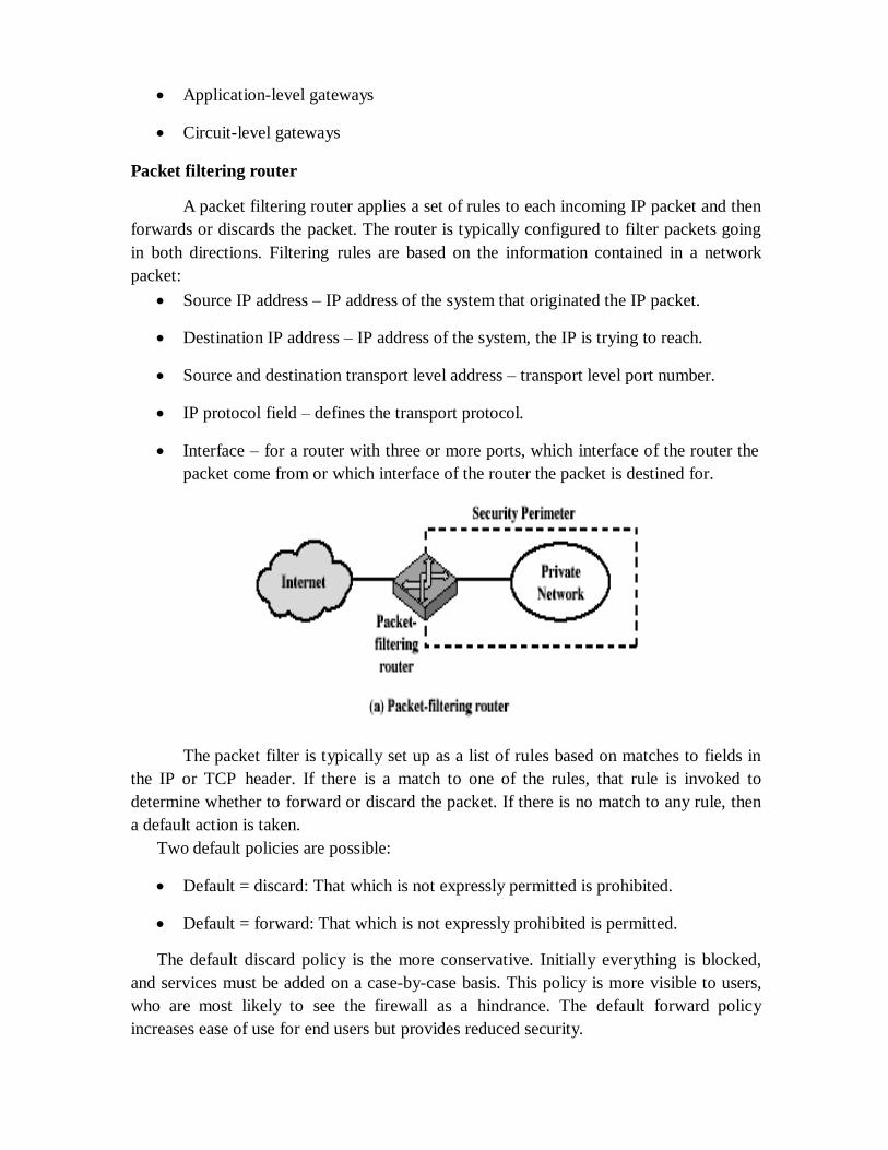
Application-level gateways
Circuit-level gateways
Packet filtering router
A packet filtering router applies a set of rules to each incoming IP packet and then
forwards or discards the packet. The router is typically configured to filter packets going
in both directions. Filtering rules are based on the information contained in a network
packet:
Source IP address – IP address of the system that originated the IP packet.
Destination IP address – IP address of the system, the IP is trying to reach.
Source and destination transport level address – transport level port number.
IP protocol field – defines the transport protocol.
Interface – for a router with three or more ports, which interface of the router the
packet come from or which interface of the router the packet is destined for.
The packet filter is typically set up as a list of rules based on matches to fields in
the IP or TCP header. If there is a match to one of the rules, that rule is invoked to
determine whether to forward or discard the packet. If there is no match to any rule, then
a default action is taken.
Two default policies are possible:
Default = discard: That which is not expressly permitted is prohibited.
Default = forward: That which is not expressly prohibited is permitted.
The default discard policy is the more conservative. Initially everything is blocked,
and services must be added on a case-by-case basis. This policy is more visible to users,
who are most likely to see the firewall as a hindrance. The default forward policy
increases ease of use for end users but provides reduced security.

Advantages of packet filter router
Simple
Transparent to users
Very fast
Weakness of packet filter firewalls
Because packet filter firewalls do not examine upper-layer data, they cannot
prevent attacks that employ application specific vulnerabilities or functions.
Because of the limited information available to the firewall, the logging
functionality present in packet filter firewall is limited.
It does not support advanced user authentication schemes.
They are generally vulnerable to attacks such as layer address spoofing.
Some of the attacks that can be made on packet filtering routers and the appropriate
counter measures are the following:
IP address spoofing – the intruders transmit packets from the outside with a
source IP address field containing an address of an internal host.
Countermeasure: to discard packet with an inside source address if the packet
arrives on an external interface.
Source routing attacks – the source station specifies the route that a packet should
take as it crosses the internet; i.e., it will bypass the firewall.
Countermeasure: to discard all packets that uses this option.

Tiny fragment attacks – the intruder create extremely small fragments and force
the TCP header information into a separate packet fragment. The attacker hopes
that only the first fragment is examined and the remaining fragments are passed
through.
Countermeasure: to discard all packets where the protocol type is TCP and the IP
fragment offset is equal to 1.
Stateful Inspection
Stateful packet filtering is an enhancement to dynamic packet filtering. A stateful
inspection firewall examines the state of any active network connections and based on this
information determines what packets to accept or reject. This is an active process that does
not rely on static rules. The advantages of dynamic packet filtering are that it only
temporarily opens holes in the network perimeter, and has low overhead and high
throughput.
Application level gateway
An Application level gateway, also called a proxy server, acts as a relay of
application level traffic. The user contacts the gateway using a TCP/IP application, such
as Telnet or FTP, and the gateway asks the user for the name of the remote host to be
accessed. When the user responds and provides a valid user ID and authentication
information, the gateway contacts the application on the remote host and relays TCP
segments containing the application data between the two endpoints.
Application level gateways tend to be more secure than packet filters. It is easy to
log and audit all incoming traffic at the application level. A prime disadvantage is the
additional processing overhead on each connection.
Circuit level gateway
Circuit level gateway can be a stand-alone system or it can be a specified function
performed by an application level gateway for certain applications. A Circuit level
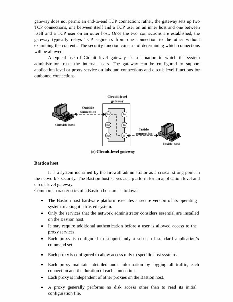
gateway does not permit an end-to-end TCP connection; rather, the gateway sets up two
TCP connections, one between itself and a TCP user on an inner host and one between
itself and a TCP user on an outer host. Once the two connections are established, the
gateway typically relays TCP segments from one connection to the other without
examining the contents. The security function consists of determining which connections
will be allowed.
A typical use of Circuit level gateways is a situation in which the system
administrator trusts the internal users. The gateway can be configured to support
application level or proxy service on inbound connections and circuit level functions for
outbound connections.
Bastion host
It is a system identified by the firewall administrator as a critical strong point in
the network‘s security. The Bastion host serves as a platform for an application level and
circuit level gateway.
Common characteristics of a Bastion host are as follows:
The Bastion host hardware platform executes a secure version of its operating
system, making it a trusted system.
Only the services that the network administrator considers essential are installed
on the Bastion host.
It may require additional authentication before a user is allowed access to the
proxy services.
Each proxy is configured to support only a subset of standard application‘s
command set.
Each proxy is configured to allow access only to specific host systems.
Each proxy maintains detailed audit information by logging all traffic, each
connection and the duration of each connection.
Each proxy is independent of other proxies on the Bastion host.
A proxy generally performs no disk access other than to read its initial
configuration file.

Each proxy runs on a non privileged user in a private and secured directory on the
Bastion host.
Firewall configurations
There are 3 common firewall configurations.
1. Screened host firewall, single-homed basiton configuration
In this configuration, the firewall consists of two systems: a packet filtering router and a
bastion host. Typically, the router is configured so that
For traffic from the internet, only IP packets destined for the basiton host are
allowed in.
For traffic from the internal network, only IP packets from the basiton host are
allowed out.
The basiton host performs authentication and proxy functions. This configuration has
greater security than simply a packet filtering router or an application level gateway
alone, for two reasons:
This configuration implements both packet level and application level filtering,
allowing for considerable flexibility in defining security policy.
An intruder must generally penetrate two separate systems before the security of
the internal network is compromised.
2. Screened host firewall, dual homed basiton configuration
In the previous configuration, if the packet filtering router is compromised, traffic could
flow directly through the router between the internet and the other hosts on the private
network. This configuration physically prevents such a security break.

3. Screened subnet firewall configuration
In this configuration, two packet filtering routers are used, one between the basiton host
and internet and one between the basiton host and the internal network. This
configuration creates an isolated subnetwork, which may consist of simply the basiton
host but may also include one or more information servers and modems for dial-in
capability. Typically both the internet and the internal network have access to hosts on
the screened subnet, but traffic across the screened subnet is blocked. This configuration
offers several advantages:
There are now three levels of defense to thwart intruders.
The outside router advertises only the existence of the screened subnet to the
internet; therefore the internal network is invisible to the internet.
Similarly, the inside router advertises only the existence of the screened subnet to
the internal network; therefore the systems on the internal network cannot
construct direct routes to the internet.
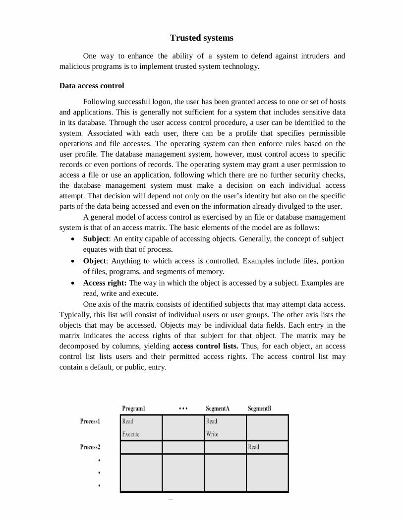
Trusted systems
One way to enhance the ability of a system to defend against intruders and
malicious programs is to implement trusted system technology.
Data access control
Following successful logon, the user has been granted access to one or set of hosts
and applications. This is generally not sufficient for a system that includes sensitive data
in its database. Through the user access control procedure, a user can be identified to the
system. Associated with each user, there can be a profile that specifies permissible
operations and file accesses. The operating system can then enforce rules based on the
user profile. The database management system, however, must control access to specific
records or even portions of records. The operating system may grant a user permission to
access a file or use an application, following which there are no further security checks,
the database management system must make a decision on each individual access
attempt. That decision will depend not only on the user‘s identity but also on the specific
parts of the data being accessed and even on the information already divulged to the user.
A general model of access control as exercised by an file or database management
system is that of an access matrix. The basic elements of the model are as follows:
Subject: An entity capable of accessing objects. Generally, the concept of subject
equates with that of process.
Object: Anything to which access is controlled. Examples include files, portion
of files, programs, and segments of memory.
Access right: The way in which the object is accessed by a subject. Examples are
read, write and execute.
One axis of the matrix consists of identified subjects that may attempt data access.
Typically, this list will consist of individual users or user groups. The other axis lists the
objects that may be accessed. Objects may be individual data fields. Each entry in the
matrix indicates the access rights of that subject for that object. The matrix may be
decomposed by columns, yielding access control lists. Thus, for each object, an access
control list lists users and their permitted access rights. The access control list may
contain a default, or public, entry.

a. Access matrix
Access control list for Program1:
Process1 (Read, Execute)
Access control list for Segment A:
Process1 (Read, Write)
Access control list for Segment B:
Process2 (Read)
b. Access control list
Capability list for Process1:
Program1 (Read, Execute)
Segment A (Read)
Capability list for Process2:
Segment B (Read)
c. Capability list
Fig: Access Control Structure
Decomposition by rows yields capability tickets. A capability ticket specifies
authorized objects and operations for a user. Each user has a number of tickets and may
be authorized to loan or give them to others. Because tickets may be dispersed around the
system, they present a greater security problem than access control lists. In particular, the
ticket must be unforgeable. One way to accomplish this is to have the operating system
hold all tickets on behalf of users. These tickets would have to be held in a region of
memory inaccessible to users.
The concept of Trusted Systems
When multiple categories or levels of data are defined, the requirement is referred
to as multilevel security. The general statement of the requirement for multilevel security
is that a subject at a high level may not convey information to a subject at a lower or
noncomparable level unless that flow accurately reflects the will of an authorized user.
For implementation purposes, this requirement is in two parts and is simply stated. A
multilevel secure system must enforce:
No read up: A subject can only read an object of less or equal security level. This
is referred to as simple security property.

No write down: A subject can only write into an object of greater or equal
security level. This is referred to as *-property (star property).
These two rules, if properly enforced, provide multilevel security.
Reference Monitor concept
The reference monitor is a controlling element in the hardware and operating
system of a computer that regulates the access of subjects to objects on the basis of
security parameters of the subject and object. The reference monitor has access to a file,
known as the security kernel database that lists the access privileges (security clearance)
of each subject and the protection attributes (classification level) of each object. The
reference monitor enforces the security rules and has the following properties:
Complete mediation: The security rules are enforced on every access, not just, fr
example, when a file is opened.
Isolation: The reference monitor and database are protected from unauthorised
modification.
Verifiability: The reference monitor‘s correctness must be provable. That is, it
must be possible to demonstrate mathematically that the reference monitor
enforces the security rules and provides complete mediation and isolation.
Important security events, such as detected security violations and
authorized changes to the security kernel database, are stored in the audit file.
Fig: Reference Monitor Concept

CS6701-CNS
M.I.E.T./CSE/IV/CNS
Importance of Standards:
It has long been accepted in the telecommunications industry that standards are required to govern the
physical, electrical, and procedural characteristics of communication equipment.
Advantages of standards are:
• A standard assures that there will be a large market for a particular piece of equipment or software. This
encourages mass production and, in some cases, the use of large scale integration (LSI) or very large
scale
integration (VLSI) techniques, resulting in lower costs.
•A standard allows products from multiple vendors to communicate, giving the purchaser more flexibility
in equipment selection and use.
Disadvantages of standards are:
• A standard tends to freeze the technology. By the time a standard is developed, subjected to review and
compromise, and promulgated, more efficient techniques are possible.
• There are multiple standards for the same thing. Fortunately, in recent years the various standards
making organizations have begun to cooperate more closely. There are still areas where multiple
conflicting standards exist.
INTERNET STANDARDS AND THE INTERNET SOCIETY
The Internet Organizations and RFC Publication
The Internet Society is the coordinating committee for Internet design, engineering, and management.
Areas covered include the operation of the Internet itself and the standardization of
protocols used by end systems on the Internet for interoperability. Three organizations under the Internet
Society are responsible for the actual work of standards development and publication:
• Internet Architecture Board (IAB):Responsible for defining the overall architecture of the Internet,
providing guidance and broad direction to the IETF
• Internet Engineering Task Force (IETF):The protocol engineering and development arm of the Internet
• Internet Engineering Steering Group (IESG):Responsible for technical management of IETF activities
and the Internet standards process.
The Standardization Process
The decision of which RFCs become Internet standards is made by the IESG, on therecommendation of
the IETF. To become a standard, a specification must meet the following
criteria:
•Be stable and well understood
•Be technically competence
•Have multiple, independent, and interoperable implementations with substantial operational experience
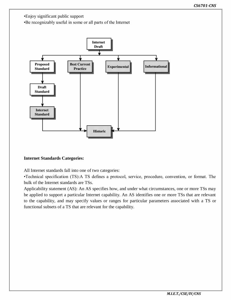
CS6701-CNS
M.I.E.T./CSE/IV/CNS
•Enjoy significant public support
•Be recognizably useful in some or all parts of the Internet
Internet Standards Categories:
All Internet standards fall into one of two categories:
•Technical specification (TS):A TS defines a protocol, service, procedure, convention, or format. The
bulk of the Internet standards are TSs.
Applicability statement (AS): An AS specifies how, and under what circumstances, one or more TSs may
be applied to support a particular Internet capability. An AS identifies one or more TSs that are relevant
to the capability, and may specify values or ranges for particular parameters associated with a TS or
functional subsets of a TS that are relevant for the capability.