Embed Size (px)
Citation preview

Coupling to FEAp g
Collier Research Corporation© 2008 Collier Research Corp.
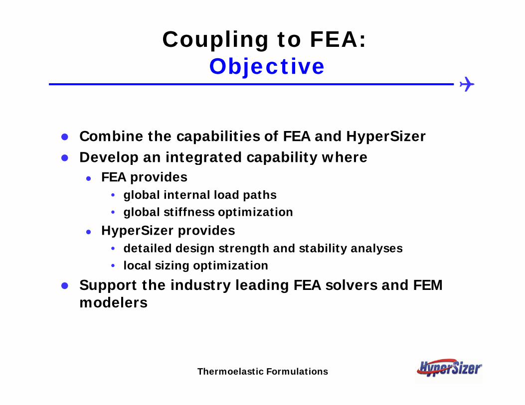
Coupling to FEA:Obj tiObjective
Combine the capabilities of FEA and HyperSizerDevelop an integrated capability whereDevelop an integrated capability where
FEA provides • global internal load paths • global stiffness optimization
HyperSizer provides• detailed design strength and stability analyses• detailed design strength and stability analyses• local sizing optimization
Support the industry leading FEA solvers and FEM d lmodelers
Thermoelastic Formulations

Coupling to FEA:T h i l A hTechnical Approach
1 Accurately and consistently couple HyperSizer panel and1. Accurately and consistently couple HyperSizer panel and beam thermoelastic stiffness formulations with FEM
2. Automate the process of data exchange between p gHyperSizer and finite element solvers and modelers
use NASTRAN bulk data file as a fundamental file formatintegrate directly with commercial finite element modelingintegrate directly with commercial finite element modeling packages via their native databases or neutral filesdisplay HyperSizer results in the native modeler’s graphicsdisplay FEA computed loads in HyperSizer’s graphicsdisplay FEA computed loads in HyperSizer s graphics
3. Use statistical methods to “pull-loads” from the FEA and to determine appropriate design-to loads
4. Perform loads calculations offline from FEA when applicable to reduce element count and fine meshes
Thermoelastic Formulations

The Process of Coupling FEA with H SiHyperSizer
H Si i bl i ht idHyperSizer is blue right side. HyperSizer sends to the FEM:
1. Properties: PSHELL & PBAR
2. Materials:
Composite = MAT2
Isotropic = MAT1Isotropic MAT1
FEA is blue left side. FEA sends to HyperSizer:
1. Internal loads
Element forces = F06
The iterative process of pexchanging element forceand element stiffness data is repeated until the design sizes converge
Coupling to FEA

FEA Commercial Solvers and M d l S t dModelers Supported
Currently SupportedMSC/NASTRAN l b lk d t filMSC/NASTRAN solver -- bulk data fileI-DEAS solver and modeler -- universal fileFEMAP modeler neutral fileFEMAP modeler-- neutral file
Planned to be SupportedPATRAN modelePATRAN modelerANSYS solver and modeler
FEA Commercial SupportIndex Top
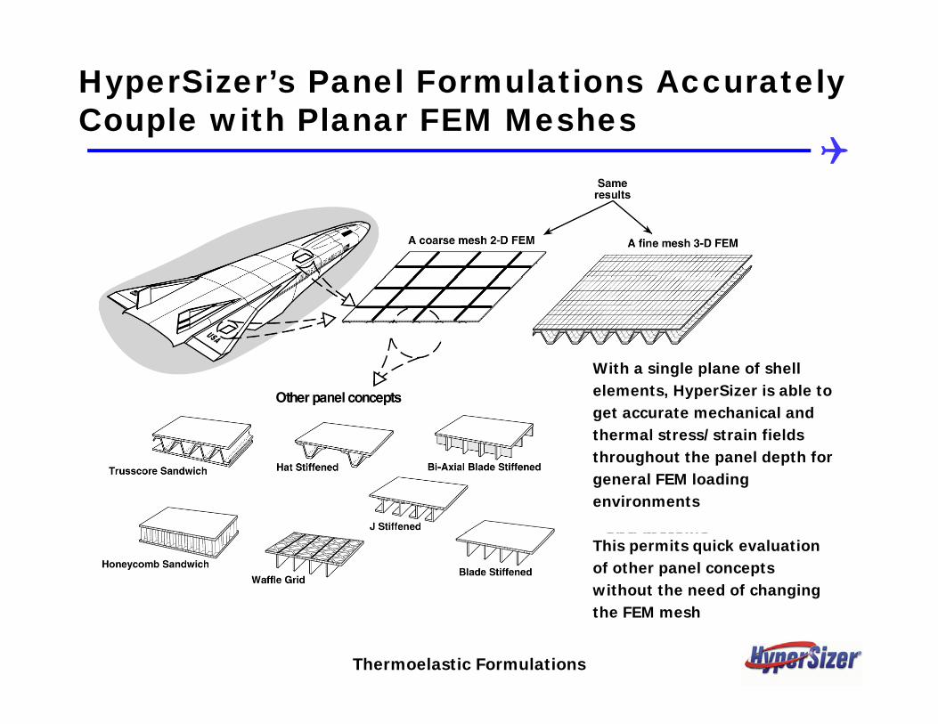
HyperSizer’s Panel Formulations Accurately Couple with Planar FEM Meshes
i h i l l f h llWith a single plane of shell elements, HyperSizer is able to get accurate mechanical and thermal stress/strain fields throughout the panel depth for general FEM loading environments
This permits quick evaluation of other panel concepts without the need of changing the FEM mesh
Thermoelastic Formulations

Comparison between MSC/NASTRAN and I-DEAS with H Si A t ti ll G t d M d l D tHyperSizer Automatically Generated Model Data
This is not meant to be a comparison of one product to another, but to provide verification that HyperSizer is completely coupled to each product. Though the model is simple, this test case was
260.
230.
200.MSC/NASTRAN Peak Deflection
HyperSizer is completely coupled to each product. Though the model is simple, this test case was significant in that many of the challenging FEM data were included such as thermal loads, composite materials, unsymmetric and unbalanced panels; and beams with orientations, products of inertia, and offsets.
170.
140.
110.
80.
50.
20.
-10.
MSC/NASTRAN
Peak Deflection = 1.07”
-40.
-70.
-100.
-130.
-160.
-190.
-220.
260.
230.
200.
170.
140.
110.
80
I-DEASI-DEAS Peak Deflection = 1.05”80.
50.
20.
-10.
-40.
-70.
-100.
-130.
1.05
FEA Commercial Support
-160.
-190.
-220.

HyperSizer Automatic Beam Cross SectionVisualization Data for FEM Modelers
The beams are modeled as line elements/CBARHyperSizer generated the wide flange beam graphics data to display in the modeler Suchmodeler. Such visualization aids in verification
FEA Commercial SupportIndex Top

HyperSizer Automatic BeamOff t V t D fi d f th FEMOffset Vectors Defined for the FEM
The user can select from these three options to cause the beams to bethe beams to be represented in the FEM at either their neutral axis, at the beam top flange,
FEA Commercial Support
or at the beam bottom flange.

Beam Sizing Automatically Included in the FEMFuselage ringframes and longerons optimized with HyperSizer. Both I beam and C channel
ti t d b H Si d t i ti d i d d t t ti lloptions turned on by user. HyperSizer determines optimum design and updates automatically the FEM beam stiffness, offset vector, and beam visualization data. Note these beams are line elements in the model, not shell segments. The white circles are the FEM grid points at the surface OML.
FEA Commercial Support
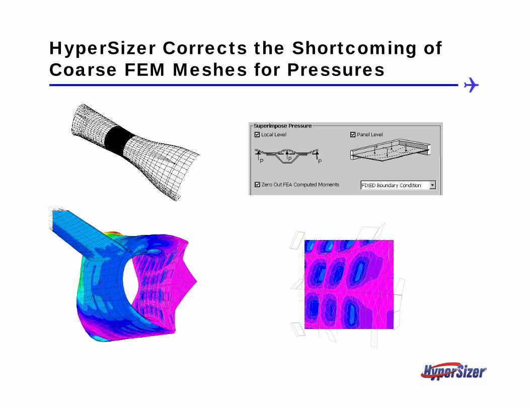
HyperSizer Corrects the Shortcoming of Coarse FEM Meshes for Pressures
"Sizing"Sizing
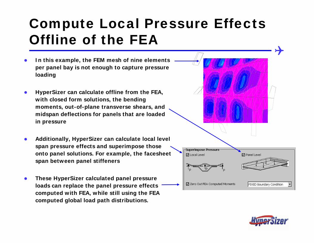
Compute Local Pressure Effects Offli f th FEAOffline of the FEA
In this example, the FEM mesh of nine elements per panel bay is not enough to capture pressure loading
HyperSizer can calculate offline from the FEA,HyperSizer can calculate offline from the FEA, with closed form solutions, the bending moments, out-of-plane transverse shears, and midspan deflections for panels that are loaded in pressurein pressure
Additionally, HyperSizer can calculate local level span pressure effects and superimpose those onto panel solutions. For example, the facesheet span between panel stiffeners
These HyperSizer calculated panel pressureThese HyperSizer calculated panel pressure loads can replace the panel pressure effects computed with FEA, while still using the FEA computed global load path distributions.

Global
Modeling the Panel
Global
2) Planar 2D mesh with stiffeners smeared in shell elements
3) Planar 2D mesh with stiffeners modeled with beam elementsbeam elements
4) Discrete 3D mesh )using shell elements for both the facesheet and stiffener web
5) Discrete 3D mesh using solid elements for both the facesheet and stiffener web
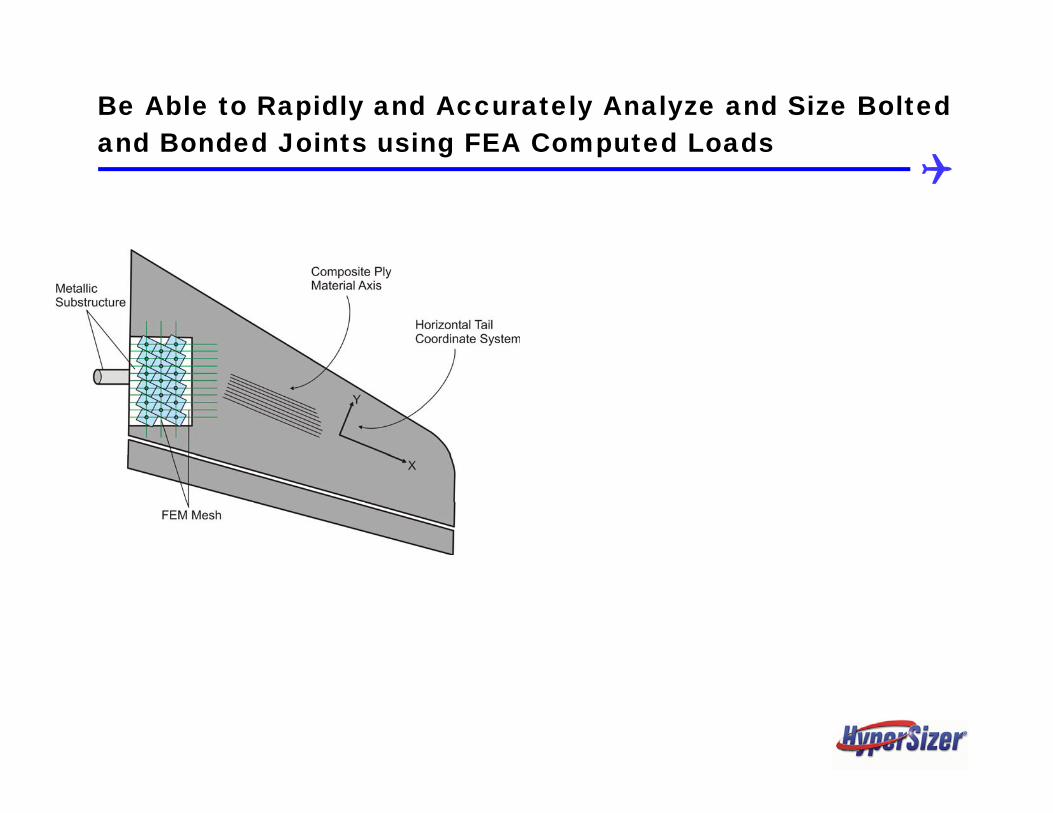
Be Able to Rapidly and Accurately Analyze and Size Bolted p y y yand Bonded Joints using FEA Computed Loads


FEA St ti ti l D i t L dFEA Statistical Design-to Loads
Solve the automated structural analysis 'pulling loads' Solve the automated structural analysis pulling-loads problem that arises when many finite elements are used to represent a structural componentp pUser may select a standard deviation factor to apply to loadings for strength analysis For instability, HyperSizer statistically determines the percentage of a component's area that is in the buckling zone and integrates the non uniform compressive load zone and integrates the non-uniform compressive load over that area
FEA Statistical Design-to Loads Index Top
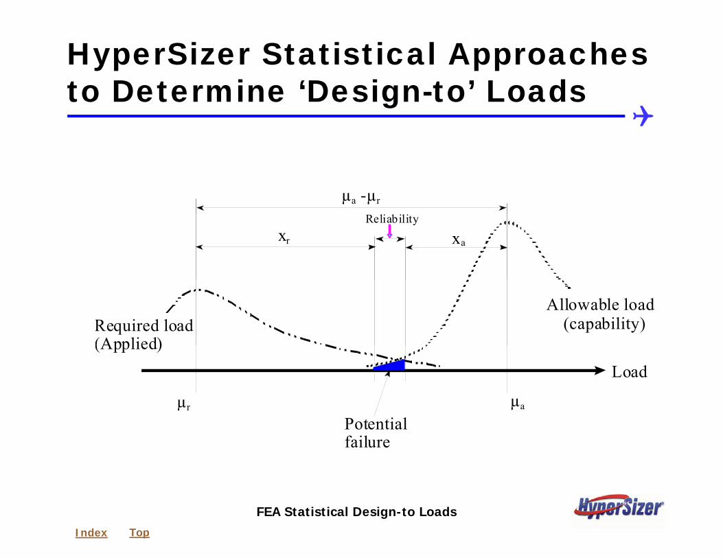
HyperSizer Statistical Approaches t D t i ‘D i t ’ L d to Determine ‘Design-to’ Loads
µa -µr
xr xa
Reliability
Allowable load (capability)Required load
(Applied)
µr µa
(Applied) Load
µPotentialfailure
FEA Statistical Design-to Loads Index Top

User Chosen Standard Deviation f St th A lfor Strength Analyses
“Design to” loading = µ + Kσ
Probability range
Design-to loading = µ + Kσ
Probability distribution
y g
KσProbability distribution
Density (Density function)
µLoad
Nijσµ NijσMean Standard
deviation“Design-to” load
FEA Statistical Design-to Loads Index Top

Global
HyperSizer Statistical Approaches to Determine ‘Design-to’ Loads
Global
L o ad S e t 1 0 4
L o ad S e t 1 0 9
L o ad S e t1 0 1 1 0 1
L o ad S e t 1 0 6
L o ad S e t 1 0 4

Global
HyperSizer Statistical Approaches to Determine ‘Design-to’ Loads
Global
µa -µr
xr xa
Reliability
a
Allowable load (capability)Required load
(Applied)
µr µa
Potentialfailure
(Applied) Load
failure
“Design-to” loading = µ + Kσ
Probability distributionDensity
Probability range
Kσ
(Density function)
µLoad
NijσMean Standard
d i ti“Design-to”e deviation load

Analyses are Independent of Loads Source
FEA C t d L d User Input (typed in loads)FEA Computed Loads User Input (typed-in loads)
Other Sources Using HyperSizer’s Object Model:
Loads from spreadsheets
HyperSizer AnalysesLoads from a larger company software design system
yp y