Embed Size (px)
Citation preview

Coupling Thermal Integration of a Solid Oxide Fuel Cell with a Magnesium Metal
Hydride Tank
E.I Gkanas1,2
, S.S Makridis1,2
, A.K Stubos1
1 Institute of Nuclear and Radiological Sciences, Energy, Technology and Safety, NCSR “Demokritos”,
Aghia Paraskevi, Athens, 15310, Greece
2 Institute for Renewable Energy and Environmental Technologies, University of Bolton, Deane Road,
Bolton, BL3 5AB, UK
Abstract
The dehydriding behavior of a cylindrical Mg metal hydride tank is simulated and examined in the case
where the tank is thermally coupled with an operating Solid Oxide Fuel Cell (SOFC) at 7000C. A three-
dimensional validated mathematical model is utilized to simulate the hydrogen desorption from a cylindrical
Mg hydride tank. Four scenarios are simulated: a base case where the heat source for the desorption process
is an external heater surrounding the tank. The second case examines the effect of the radiation heat transfer
from the SOFC to the metal hydride as a possible heat source for the desorption procedure. The third
scenario uses the exhaust air from the SOFC cathode as the heating source which is driven to the hydride
and the fourth scenario is a combination of both the exhaust air from the SOFC cathode and the external
heater as the heat source for the desorption. According to the results, the exhaust air from the SOFC and the
combination of external heater and the exhaust heat have a uniform temperature distribution within the tank
and enhance the desorption capacity.
Keywords: Hydrogen storage; Thermal coupling; SOFC; Heat transfer; Dynamic model
1. Introduction
Hydrogen storage in reversible metal hydrides is desirable for use in applications such as hybrid electric
vehicles [1] because hydrogen can be stored at low pressures with a high volumetric density [2]. Further,
hydrogen can be used essentially pollution free and produced from renewable energy resources, thus
eliminating the net production of greenhouse gases. Hydrogen storage in metal hydrides is also particularly
advantageous for stationary or small-scale fuel cell applications where the desire for small storage tank
outweighs the disadvantages of the hydride mass [3].
The main drawback for the metal hydride storage systems, is the limited heat transfer between the external
heat source (external water bath, spiral coil surrounding the tank, etc.), and the metal hydride within the
tank, where the reaction takes place [4]. The heat transfer rate can determine the rate of hydrogen
desorption [5] and by increasing these rates inside the hydride tanks is crucial for optimizing the design of
hydrogen storage applications. Methods to increase the heat transfer by manipulating the internal properties
of the storage vessels have been proposed. These methods include: Insertion of nickel or aluminum foam
inside the tank [6, 7], integration of copper wire net structure [8], compacting metal hydride powders with
expanded graphite [9] and internal heat exchangers [10].
When hydrogen is released from the metal hydride bed, the endothermic desorption process causes the
temperature inside the metal hydride to decrease [11]. As a result, this temperature decrease inside the metal
hydride tank diminishes the rate at which hydrogen releases from the tank. In order to eliminate the effect,
some of the heat naturally produced from a Solid Oxide Fuel Cell (SOFC) during its operation can be
transferred to the hydride bed in order to increase the temperature of the tank. In this way, the tank can
thermally coupled with the SOFC, by using the exhaust waste heat from the SOFC and drive it to the tank or
by using the irradiation heat transfer from the SOFC to the surface of the tank due to the high operating
temperatures of the SOFC.
MacDonald et al. [12] studied the behavior of a thermally coupled metal hydride tank containing
Ti0.98Zr0.02V0.43Fe0.09Cr0.05Mn1.5 alloy with a Proton Exchange Membrane fuel cell (PEMFC), by using three
different geometries for the tank. They exported that the annular tank could provide hydrogen gas at the
required flow rate and pressure stimulated by the fuel cell. Jiang et al. [13] studied the behavior of a
thermally coupled hydrogen storage tank and a PEMFC, where the effect of transferring waste thermal
energy from the fuel cell to the hydride was examined. They pointed the importance of providing energy to
the metal hydride bed in order to facilitate the desorption process. Delhomme et al. [14] presented an
experimental setup designed to test the thermal integration of a MgH2 tank with an operating SOFC. It was
extracted that using the heat exhaust from the SOFC to provide heat to the hydride bed is feasible only as
long as the gas is found at a sufficiency high temperature (above 350-400 0C) to the tank.
Among all the metals used for the formation of hydrides, Magnesium has the highest energy density and the
storage capacity that presents is 7.6 wt%. The main drawback of using MgH2 as a hydrogen storage vessel is
the requirement of medium grade heat (350 0C) for the desorption process [15-17]. In order to maintain or
even optimize the desorption of hydrogen from a MgH2 tank, the coupling and thermal integration with the
SOFC seems a very promising option. Heat is released from the SOFC stack at high temperature (800-850 0C) [18, 19] and can be used to enhance the release of hydrogen within the MgH2 tank
The current study aims to improve the understanding of the hydrogen desorption process within MgH2
storage system by taking account and simulating four different scenarios for each hydride. The first scenario
deals with the simulation of the desorption process of the hydrides without taking into account the coupling
with the SOFC, where the energy for the endothermic desorption is given by an external heater. The second
scenario involves, for the very first time, according to the current knowledge of the authors, the effect of the
irradiation heat transfer from the high temperature operating SOFC to the desorbing metal hydride bed. For
the third scenario, the exhaust air from the operating SOFC is driven to the metal hydride with the use of
pipes and finally, a combination of the external heater and exhaust gas heat transfer is studied in order to
decide which of the scenarios have the greater efficiency at the hydrogen desorption process. The above
scenarios expose the advantages of providing waste heat energy from the SOFC stack to the metal hydride
bed in order to facilitate the removal of hydrogen. For the current study, the geometry of the SOFC and the
metal hydride tank was implemented in a finite element program called COMSOL Multiphysics.
2. Mathematical Modeling of the Hydrogen Desorption Process.
2.1 Geometry of the Metal Hydride Tank
The metal hydride bed used in the current study, consists of a cylindrical container of radius R=0.05m and
height H=0.5m which contains the metal powder that chemically absorbs the hydrogen under pressure. For
the simulation studies, four different geometries are considered, based on the cylindrical container. The first
geometry consists of the cylindrical container with a small cylinder at the basis, which is the hydrogen
supply canister, and the heat source is an external heater. The second geometry is also a cylindrical container
with the same dimensions while in this case the heat source is the heat flux from the radiation from an
operating SOFC. The third geometry is a cylindrical container thermally connected via pipes to the operating
SOFC where the exhaust heat from the SOFC is passing the metal hydride through a co-axial heat exchanger
to the cylindrical container and the final geometry consists of a thermally coupled SOFC and the metal
hydride tank with pipes, while the heat source is a combination of both external heater and the exhaust heat
from the SOFC. Fig. 1 illustrates the four different geometries under operating conditions, where the
hydrogen desorption is taking place.

Fig. 1. Geometries of the simulation study. Fig 1a. represents the hydrogen desorption by using the external heater as the heat
source for desorption. Fig 1b. illustrates the use of radiation heat from the SOFC as heat source for desorption. Fig 1c. shows the
geometry with the exhaust heat from SOFC as the heat source and Fig. 1d shows the geometry where both external heater and the
exhaust from the SOFC are used as the heat source for the desorption.
2.2 Problem Formulation
The governing equations, consist of energy, mass and momentum conservation which described by partial
differential equations, and some other equations that describe the kinetics of absorption and desorption [20,
21]. The model describes also the diffusion through the hydride bed, by using the Darcy’s law and taking
into consideration the kinetics of absorption as a function of the difference between the local and
equilibrium temperature.
In order to study the hydrogen desorption process in a metal hydride bed, simulations are performed using
COMSOL Multiphysics 4.2, as it is specialized in solving the coupled heat and mass transfer problems in
porous media. Further, this software takes into account the gas transport (diffusion and flow) pressure
gradients inside the hydride beds and the reaction kinetic inside the alloys. In the current simulation study
Mg powder is considered inside the metal hydride tank. The operating conditions and physical properties of
magnesium hydride and hydrogen at 600 K, are presented in Table 1.

Table 1. Operating conditions and physical parameters of magnesium hydride and hydrogen
The modules added in the current model are the heat transfer in porous media module which includes the
energy conservation equation, the Darcy’s law module including the momentum conservation equation and
the transport in diluted species module containing the mass conservation equation. In order to simplify the
problem, some assumptions made such as:
The medium (gas and metal) initially are in local thermal equilibrium
The solid phase is isotropic and has uniform porosity
In order to be able to calculate for every temperature the hydrogen density, the hydrogen is treated as
an ideal gas
The thermophysical properties of the hydride bed are independent of the bed’s temperature and the
hydrogen supply temperature
The effect of hydrogen conservation on the variation of the equilibrium pressure is negligible.
2.2.1 Energy Conservation Equation
Assuming thermal equilibrium between the hydride powder and hydrogen, a single energy equation
is solved instead of separate equations foe both solid and gaseous phases.
( ) ( )
( ) ( ( ))
e g g g
e g s
TCp Cp v T
t
k T m T Cp Cp
(1)
Considering only parallel heat conduction in solid and gas phases, there are the following expressions for
specific heat and thermal conductivity respectively:
( ) ( ) ((1 ) )e g g s sCp Cp Cp (2)
(1 )e g sk k k (3)
Both the equations (2) and (3) are expressed as porosity – weighted functions of the hydrogen – gas and the
solid – metal phases.
Parameter Value
Desorption Enthalpy ΔH -75500 (J/mol)
Desorption Entropy ΔS -135.6 (J/K/mol)
Porosity ε 0,654
Mg Heat Capacity Cp 1545 (J/kg/K)
Mg Thermal Conductivity λ 0,48 (W/m/K)
Mg Density ρMg 1800 (kg/m3)
Initial Temperature T0 320 (0C)
Initial Pressure P0 0.8 (bar)
External Heater Temperature Tinf 350 (0C)
SOFC Operating Temperature Top 700 (0C)
Hydrogen Dynamic Viscosity μ 8.6 10-6
(Pa s) [30]
Hydrogen Molecular Mass Mgas 0.002 (kg/mol)
Hydrogen Thermal Conductivity λH2 0.18 (W/m/K)

2.2.2 Hydride Mass Balance
For the solid, a mass conservation equation is considered.
( )(1 ) s m
t
(4)
2.2.3 Hydrogen mass balance
The mass conservation for the gas is considered as:
( )
( )g
g gdiv v mt
(5)
2.2.4 Momentum equation
The gas velocity can be expressed using Darcy’s law. By neglecting the gravitational effect, the equation is
the above:
( )g g
g
Kv grad P
(6)
Where K is the permeability of the solid and μg is the dynamic viscosity of gas. The solid permeability is
given by the Kozeny – Carman’s equation:
2 3
2180 (1 )
dpK
(7)
Assuming that the hydrogen is an ideal gas, from the perfect gas law (ρg = (Pg Mg)/(RT)) and considering
Darcy’s law, the mass conservation equation of hydrogen becomes:
2
2
1g g g g
g g
g g
P M P
R T t R T t T
r P PK Km
v r r r v z
(8)
2.2.5 Desorption Kinetic Expression
For the desorption process, the following expression is used in order to describe the kinetics.
exp[ ] ( ) ( )eq gd
d s
g eq
P pEm C
R T P
(9)
Where m is the source term and used in equations (1), (4), (5), (8). Cd is pro-exponential constant for
desorption, Ed is the activation energy for desorption, ρs is the solid density, and ρo is the initial metal
hydride density.
2.2.6 Equilibrium Pressure
The equilibrium pressure for the hydrogen, which is the most important parameter which defines if the
reaction is going to take place or not, is given by van’t Hoff law:

ln eq
g g
SP
R T R
(10)
2.3 Model Validation
When simulating a problem, verification of the proposed model and the simulation results is required to
ensure that the model does what is intended to do. Validation of the current model has been performed by
comparing the extracted simulation results to experimental results already been published. Figure 2 shows
the comparison between the experimental results by Dornheim et al. [22] and the simulating results
according to the proposed model for three different cases. For hydrogen desorption from a pure-Mg hydride
tank, for nanocrystalline Mg hydride tank and for a Nb2O5 catalyzed Mg hydride tank. As extracted from the
results the desorption curves presents similar behavior for all the cases, including very slow kinetics for the
pure Mg and much faster for the other two cases.
0 100 200 300 400 500 600 700
-1
0
1
2
3
4
5
6
7
8
Des
orpt
ion
Cap
acity
(wt%
)
Time (s)
Dornheim et al [23] Pure Mg
Simulation Results Pure Mg
Dornheim et al [23] Nanocrystalline Mg
Simulation Results Nanocrystalline Mg
Dornheim et al [23] Mg catalyzed with Nb2O
5
Simulation Results Mg catalyzed with Nb2O
5
Fig. 2. Validation of the proposed model with the experimental results by Dornheim et al [22].
3. Radiation Heat Transfer Modeling
Generally, SOFCs operates at high temperatures between 600-1000 0C [23] and due to the high operating
temperatures, radiation heat transfer must be given special consideration in thermal modeling efforts. Damn
et al. [24] proposed a model of radiative heat transfer within the SOFC, assuming that the outer surface of
the SOFC stack as an isothermal surface, in order to maintain the temperature inside the stack. In the current
work the radiation heat transfer from the outer surface of the stack to the surface of the metal hydride tank is
simulated, in order to use the heat origin from the operating SOFC as the heat source to maintain the
desorption process.
The governing equations for radiative heat transfer are integral-differential equations, and they are not
linear, as the emissive power features a fourth-power dependence on the temperature. Many researchers used
different methods to model the radiation heat transfer [25-28]. In order to propose a single mathematical
model, the SOFC’s outer surface and the hydrides outer surface are assumed as opaque, diffuse and grey
surfaces. The radiosity, represents the rate at which radiation energy leaves a unit of a surface in all
directions. For an opaque surface, the radiosity is expressed by:
4(1 )m mJ G T (11)

Where J is the radiosity (W/m2), εm is the surface emissivity, G is the irradiation (W/m
2) and σ is the Stefan-
Boltzmann constant (5.67 10-8
W/m2K
4). The radiation heat flux incident on a surface from all directions is
called irradiation G and is expressed as [29]:
m amb ambG G F T (12)
Where Gm is the mutual irradiation coming from the other surfaces in the model and is expressed as:
' '
21
( )( )N
m
j
n r nrG
n r
(13)
The above equations, Eq. (11), Eq. (12) and Eq. (13) are used in order to calculate the radiation flux from
the operating SOFC to the metal hydride tank.
4. Results and Discussion
For the SOFC operation, it is assumed that the SOFC is servicing an intermittent load cycling with a 30 min
period. The on-cycle then lasts for 15 min and this is the time range where the thermal coupling effect
between the operating SOFC and the metal hydride tank will be examined. Further, four different scenarios
about the thermal coupling will be simulated and discussed. The first scenario is a “reference” scenario,
where the heat for the desorption process within the tank is offered to the system by an external heater. The
second scenario uses the heat from the irradiation heat flux from the operating SOFC to the metal hydride
tank. The third scenario involves the exhaust heat from the operating SOFC to the metal hydride bed and the
fourth scenario is a combination between the exhaust heat from the operating SOFC to the metal hydride bed
and the external heater in order the hydride tank to release the hydrogen. Further, for the second scenario, a
separate study will be performed in order to clarify the role of the radiative heat transfer from the SOFC to
the hydride tank. The temperature and hydrogen concentration profiles across the z-axis of the metal hydride
tank will be examined and discussed and finally five different “thermocouples” named as TC1, TC2, TC3,
TC4, TC5 were assumed inside the hydride tank in order to be able to measure the temperature, pressure and
concentration inside the tank. The position of these “thermocouples” is shown if Fig. 3.
Fig. 3. The position of the five “thermocouples” inside the metal hydride tank

4.1 Hydrogen desorption with the heat from the external heater.
According to Table 1, the initial temperature of the hydride tank is 320 0C and the external heater is at 350
0C. The simulation runs were performed for 15 min (900 s), which is the time where the SOFC last for the
on-cycle. Fig. 4 presents the temperature profile of the metal hydride tank across the z-axis of the tank as
shown in Fig. 3. The temperature deviation is not uniform within the hydride tank. The heat is provided at
the external surfaces of the tank from the external heater and due to the low thermal conductivity of the
metal hydride, the temperature profile drops until the heat reaches the zone where the reaction is taking
place. It is also notable that the lower temperature is at the center of the hydride tank indicating that the
desorption process has a preferred direction from the outer of the tank to the middle of the tank.
-0.08 -0.06 -0.04 -0.02 0.00 0.02 0.04 0.06 0.08
320
325
330
335
340
345
350
Tem
pera
ture
(0
C)
z-axis lenght (m)
900s
700s
500s
300s
100s
50s
Time
Fig. 4. Temperature profiles across the z-axis of the hydride tank for different times for the hydrogen desorption with the heat
provided by external heater.
Fig. 5 illustrates the concentration of the desorbed hydrogen within the metal hydride tank along the z-axis.
It is notable that the desorption process is symmetrical with the symmetry axis to be at the center of the
hydride tank and confirms the previous assumption that the desorption process has a preferred direction
within the tank.

-0.08 -0.06 -0.04 -0.02 0.00 0.02 0.04 0.06 0.08
0.0
0.5
1.0
1.5
2.0
2.5
3.0
3.5
4.0
Des
orpt
ion
Cap
acity
(m
ol/m
3)
z-axis lenght (m)
900s
700s
500s
300s
100s
50s
30s
10s
Time
Fig. 5. Hydrogen concentration profiles across the z-axis of the hydride tank for different times for the hydrogen desorption with
the heat provided by external heater.
4.2 Hydrogen desorption with the heat from the radiation flux from the operating SOFC.
Due to the high operating temperature of SOFC, the radiative heat transfer from the SOFC to the hydride is a
crucial parameter and can be used in order to enhance the desorption process. According to [25], heat losses
from the edges of the SOFC have the potential to induce damaging thermal gradients within the cells. It was
also insisted that little has been reported about the interaction between the SOFC stack and other surfaces
outside the stack and the role of radiation heat transfer in minimizing heat losses from the stack. In the
current study, it is assumed that the SOFC emits radiative heat transfer without resulting damaging thermal
gradients within the cells.
4.2.1 Identifying appropriate conditions for radiative heat transfer from the operation SOFC to the metal
hydride tank
It is well known that the melting point of pure Mg is 650 0C. In the current simulation study it is assumed
that the SOFC operates at 700 0C. It is therefore of major concern the avoidance of heating the material
above 350-400 0C, which is a temperature range capable to maintain the desorption process of hydrogen
within the metal hydride tank. The first step when examine the effect of radiative heat transfer from the
operating SOFC to the hydride tank is to discover the conditions at which the radiation heat transfer doesn’t
damage the material (distance between SOFC and metal hydride, operating temperature, time of radiation
flux). Fig. 6 presents the effect of the radiative heat transfer between the SOFC and the metal hydride tank
after 900s of radiation where the distance between them is 0.13m and the operating temperature of the SOFC
is 700 0C.

Fig. 6. Surface radiosity after 900s of operation of the SOFC at 700 0C. The arrows represent the direction of the total heat flux.
The arrows inside the metal hydride tank represent the direction of the total heat flux within the tank and it is
obvious that the heat flux goes from the outer surface exposed to the radiation of the SOFC to the center of
the tank. Further, Fig. 7a shows the total energy flux profiles for the five “thermocouples” within the tank
and Fig. 7b shows the temperature profile for the “thermocouples”. According to these results, it seems that
the maximum temperature within the tank is 430 0C for the TC1 while for the others the temperature varies
from 332-375 0C which is a temperature range capable to maintain the desorption process. These conditions
are potential for using the radiation heat transfer for the heat source for the release of hydrogen within the
tank and will be used for the simulation of the dehydrogenation process.
Fig. 7. Temperature and Total Heat Flux profiles for all the thermocouples inside the hydride tank indicating the effect of
radiative heat transfer inside the hydride

4.2.2 Hydrogen desorption with the radiation heat transfer as heat source
The desorption process within the tank is studying, and as the heat source the radiation heat transfer from the
operating at 700 0C SOFC to the hydride tank is used. Fig. 8 illustrates the temperature profile across the z-
axis of the cylindrical hydride tank at different desorption times.
-0,06 -0,04 -0,02 0,00 0,02 0,04 0,06
320
330
340
350
360
370
380
Te
mp
era
ture
(0C
)
z-axis lenght (m)
900s
700s
500s
300s
100s
Time
Fig. 8. Temperature profiles across the z-axis of the hydride tank for different times for the hydrogen desorption with the heat
provided by the radiation heat transfer.
As extracted from the results, the temperature profile has a non-uniform distribution where the lower value
of temperature is located in the space within the metal hydride near the surface which has the lowest
radiation exposure. The highest temperature is located near the surface which exposed directly to the
radiation from the SOFC. Further, from Fig. 9, which shows the concentration of desorbed hydrogen within
the tank, the highest concentration of the desorbed hydrogen is found near the surface where the radiation
flows directly. Inside the tank, the hydrogen concentration appears to have a uniform distribution with
almost the same value across the axis, with a small rise near the surface with the lowest radiation exposure.
The results showed that in this case the desorption process has also a preferred direction from the outer
surface, directly exposed to the radiation to the center and from all the other surfaces not directly exposed to
the radiation to the center of the tank. In the case of the heat flux from the directly exposed surface the rate
of the heat transfer is higher than from the other surfaces.

-0,08 -0,06 -0,04 -0,02 0,00 0,02 0,04 0,06 0,08
0,0
0,5
1,0
1,5
2,0
2,5
3,0
3,5
4,0
De
so
rptio
n C
ap
acity (
mo
l/m
3)
z-axis lenght (m)
900s
700s
500s
300s
100s
50s
30s
10s
Time
Fig. 9. Hydrogen concentration profiles across the z-axis of the hydride tank for different times for the hydrogen desorption with
the heat provided by radiation heat transfer.
4.3 Hydrogen desorption with the heat from the exhaust gas from the operating SOFC.
Under experimental conditions, usually the SOFC cathode inlet air is supplied from a compressed air supply
line and the cathode stream is pre-heated before entering the cathode distribution manifold within the stack
[14]. The cathode exhaust is vented with the SOFC operation only, and during the thermal coupling with the
hydride tank, the cathode exhaust is mixed with fresh air at 20 0C, instead to control the temperature of the
stream entering the hydride vessel at 350 0C and thus, avoiding a partial sintering of the magnesium in the
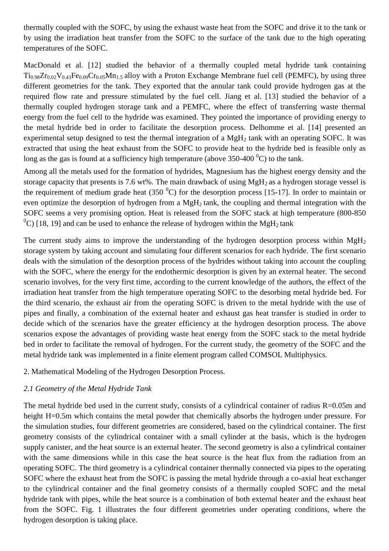
tank. In this case, is assumed that the temperature of the exhaust when entering the metal hydride tank is 350 0C and remains constant for the 15 min of the on-cycle of the SOFC. The exhaust air from the SOFC is
driven with pipes to the metal hydride tank as shown in Fig. 1c. The pipe inside the metal hydride tank is
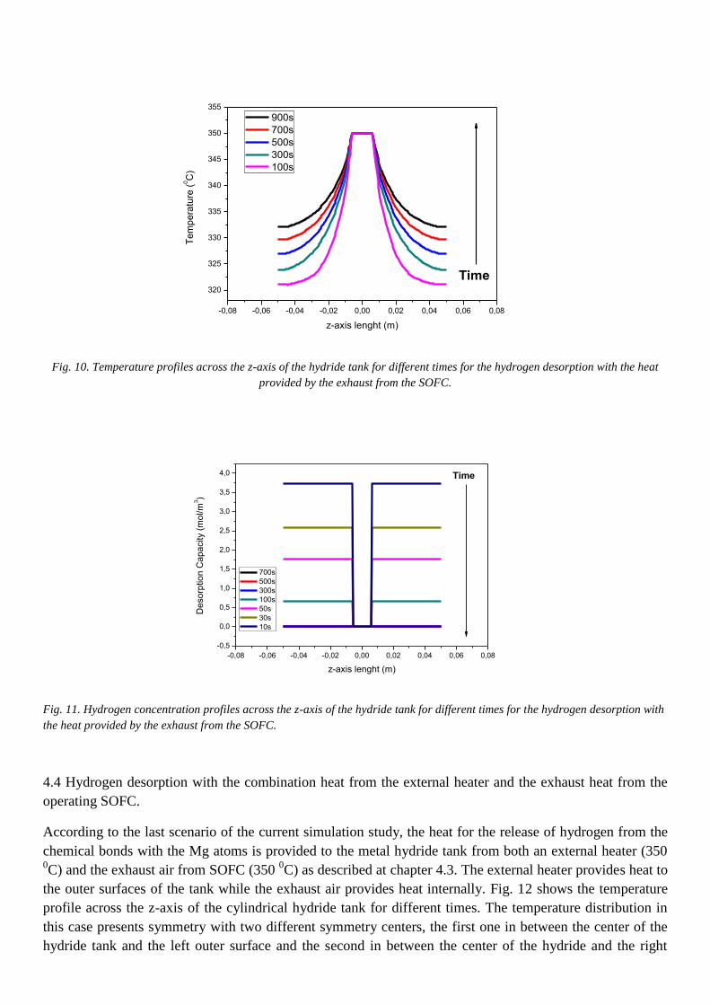
placed at the center of the cylindrical tank and also the pipes have cylindrical shape. Fig. 10 illustrates the
temperature profile within the metal hydride tank across z-axis for different desorption times. It is extracted
that the temperature profile in this case has a symmetrical shape with center of symmetry the center of the
tank where the pipe with the exhaust air is placed. As the time is passing, the temperature within the tank is
increased, but cannot reach the maximum value. This is probably due to the poor thermal conductivity. The
maximum temperatures are found near the center of the tank where the heat source has been placed and the
lower temperature values are found near the outer surfaces of the tank. Fig. 11 presents the desorbed
hydrogen concentration within the tank at various desorption times. The concentration also seems to be
symmetrical within the tank and has almost the same value for all the domains inside the tank. The
concentration profile shows that during the presence of a heating medium in the middle of the tank, the
concentration of the desorbed hydrogen within the tank is homogeneous and have almost the same
concentration everywhere inside the tank.
-0,08 -0,06 -0,04 -0,02 0,00 0,02 0,04 0,06 0,08
320
325
330
335
340
345
350
355
Te
mp
era
ture
(0C
)
z-axis lenght (m)
900s
700s
500s
300s
100s
Time
Fig. 10. Temperature profiles across the z-axis of the hydride tank for different times for the hydrogen desorption with the heat
provided by the exhaust from the SOFC.
-0,08 -0,06 -0,04 -0,02 0,00 0,02 0,04 0,06 0,08
-0,5
0,0
0,5
1,0
1,5
2,0
2,5
3,0
3,5
4,0
De
so
rptio
n C
ap
acity (
mo
l/m
3)
z-axis lenght (m)
700s
500s
300s
100s
50s
30s
10s
Time
Fig. 11. Hydrogen concentration profiles across the z-axis of the hydride tank for different times for the hydrogen desorption with
the heat provided by the exhaust from the SOFC.
4.4 Hydrogen desorption with the combination heat from the external heater and the exhaust heat from the
operating SOFC.
According to the last scenario of the current simulation study, the heat for the release of hydrogen from the
chemical bonds with the Mg atoms is provided to the metal hydride tank from both an external heater (350 0C) and the exhaust air from SOFC (350
0C) as described at chapter 4.3. The external heater provides heat to
the outer surfaces of the tank while the exhaust air provides heat internally. Fig. 12 shows the temperature
profile across the z-axis of the cylindrical hydride tank for different times. The temperature distribution in
this case presents symmetry with two different symmetry centers, the first one in between the center of the
hydride tank and the left outer surface and the second in between the center of the hydride and the right

outer surface. As time is passing, the temperature inside the hydride tank increases while the symmetry
remains. At the end of the 900s it seems that the temperature within the tank is everywhere almost the same.
-0,08 -0,06 -0,04 -0,02 0,00 0,02 0,04 0,06 0,08
325
330
335
340
345
350
Te
mp
era
ture
(0C
)
z-axis lenght (m)
900s
700s
500s
300s
100sTime
Fig. 12. Temperature profiles across the z-axis of the hydride tank for different times for the hydrogen desorption with the heat
provided by the combination of the exhaust from the SOFC and the external heater.
Fig. 13 also shows that the concentration of the desorbed hydrogen within the metal hydride tank is
homogeneous with a symmetry center in the middle of the tank as discussed in the case of the heating only
with the exhaust heat gas from the SOFC.
-0,08 -0,06 -0,04 -0,02 0,00 0,02 0,04 0,06 0,08
-0,5
0,0
0,5
1,0
1,5
2,0
2,5
3,0
3,5
4,0
4,5
De
so
rptio
n C
ap
acity (
mo
l/m
3)
z-axis lenght (m)
900s
700s
500s
300s
100s
50s
30s
10s
Time
Fig. 13. Hydrogen concentration profiles across the z-axis of the hydride tank for different times for the hydrogen desorption with
the heat provided by the combination of the exhaust from the SOFC and the external heater.

4.5 Comparison of temperature behavior within the metal hydride tank for all the simulating scenarios
Fig. 14 illustrates a comparison of the temperature deviation within the metal hydride tank for the five
thermocouples (TCs) as defined earlier. The comparison is performed for all the coupling scenarios
simulated in the current study and the results are taken after 900s of desorption process, at the end of the on-
cycle of the SOFC.
Fig. 14. Comparison of temperature deviation within the metal hydride tank. Fig. 14a shows the temperature profile for the TC1
for all the simulating scenarios, while Fig. 14b, Fig. 14c, Fig. 14d and Fig. 14e shows the temperature scenario for the TC2, TC3,
TC4 and TC5 respectively.
Temperature is increased faster at the first scenario where the external heater is consider as the heat source,
indicating that after the 900s the temperature within the tank has almost reached the external heater
temperature. The increase of the temperature is more pronounced at the outer surfaces of the tank and more
specifically at TC1 and TC5. For the radiation heat used as a heat source (second scenario) the temperature
rises relatively slow, which is explained by the mechanism, which is responsible for the temperature
increase. It should be noted that the temperature is higher and the increase rate also higher to the TCs which
are closer to the surface, which is directly exposed to the radiation flux from the SOFC. For the scenarios
which used the exhaust heat from the SOFC as the heat source (scenario 3) and the combination between the
exhaust and the external heater (scenario 4), the temperature increases relatively slow (scenario 3) and fast
(scenario 4). For the third scenario the temperature is higher to the TC2 and TC4 which are closer to the
heating pipe at the center of the metal hydride tank.
5. Conclusions
Thermal coupling between a Mg metal hydride tank and an operating SOFC at 700 0C was simulated. The
main objective of the current study was to investigate the behavior of the desorption process of the hydride
under different heat sources in order to find the best way to maintain the temperature for this endothermic
reaction. This objective was met by formulating a dynamic dehydriding model which was validated by
comparing the results extracted from the model with some experimental data already been published. Four
scenarios were proposed in order to compare the ability of the dehydriding process, by using as heat sources

an external heater, the heat from the radiation for the SOFC, the exhaust air from the SOFC and a
combination of an external heater with the exhaust air from the SOFC. The results revealed that the thermal
coupling of the SOFC with the hydride tank is capable to maintaining the temperature within the hydride
tank in almost homogeneous levels everywhere inside the tank, especially in the case of the combination of
both external heater with the exhaust heat from the SOFC. In the case of the radiative heat transfer from the
SOFC, the temperature profile presents an almost parabolic distribution with the higher temperature to be
near the surfaces which are directly exposed to the radiation.
Nomenclature
Cp specific heat capacity, J/kg/K Greek letters
T temperature, K ε porosity
v gas velocity, m/s εm surface emissivity
k kinetic coefficient, s-1
σ Stefan-Maxwell constant, (5.67 10-8
)
Wm-2
K-4
m kinetic expression for desorption ρ density, kg/m3
K permeability, m2
μ dynamic viscosity, Pas
P hydrogen pressure, Pa
R universal gas constant, JK-1
mol-1
subscripts
C desorption constant, s-1
g gas, hydrogen
E desorption activation energy, Jmol-1
s solid, metal
Peq equilibrium pressure, Pa d desorption
ΔΗ molar enthalpy for desorption, Jmol-1
eq equilibrium
ΔS molar entropy for desorption, Jmol-1
K-1
amb ambient
M hydrogen molar mass, kgmol-1
e efficient
J radiosity, Wm-2
G irradiation flux, Wm-2
operators
F view factor ∇ gradient or nabla
Gm mutual irradiation flux, Wm-2
n unit normal factor

References
[1] K.S. Jeong, B.S. Oh, J. Power Sources 105 (2002) 58-65.
[2] D.K Ross, Vacuum 80 (2006) 1084-1089.
[3] S.A. Hajimolana, M.A Hussain, W.M A. Wan Daud, Ren. Sust. En. Reviews 15 (2011) 1893-1917.
[4] B.D. MacDonald, A.M Rowe, Int. J. Hydrogen Energy 31 (2006) 1721-1731.
[5] G. Sandrock, J. Alloys Compd. 293-295 (1999) 877-888.
[6] S. Mellouli, H. Dhaou, F. Askri, A. Jemni, S. Ben Nasrallah, Int. J. Hydrogen Energy 34 (2009) 9393-9401.
[7] S. Levesque, M. Ciureanu, R. Roberge, Theodore Motyka, Int. J. Hydrogen Energy 25 (2000) 1095-1105.
[8] E. Hahne, J. Kallweit, Int. J. Hydrogen Energy 23 (1998) 107-114.
[9] C. Pohlmann, L. Röntzsch, F. Heubner, T. Weißgärber, B. Kieback, J. Power Sources 231 (2013) 97-105
[10] M. Raju, S. Kumar, Int. J. Hydrogen Energy 37 (2012) 2767-2778.
[11] S.A. Gadre, A.D. Ebner, S.A Al-Muhtaseb, J.A. Ritter, Ind. Eng. Chem. Res. 42 (2003) 1713-1722.
[12] B.D. MacDonald, A.M Rowe, J. Power Sources 161 (2006) 346-355.
[13] Z. Jiang, R.A. Dougal, S. Liu, S.A. Gadre, A.D. Ebner, J.A. Ritter, J. Power Sources 142 (2005) 92-102.
[14] B. Delhomme, A. Lanzini, G.A. Ortizoga-Villalba, S. Nachev, P. de Rango, M. Santarelli, P. Marty, P.Leone, Int. J.
Hydrogen Energy 38 (2013) 4740-4747.
[15] M. Dornheim, S. Doppiu, G. Barkhordarian, U. Boesenberg, T. Klassen, O. Gutfleisch and R. Bormann, Scripta Materialia 56
(2007) 841–846.
[16] E. Grigorova, M. Khristov, M. Khrussanova, J.-L. Bobet, P. Peshev, Int. J. Hydrogen Energy 30 (2005) 1099–1105.
[17] S.S. Makridis, E.Ι Gkanas, G. Panagakos, E.S Kikkinides, A.K Stubos, P. Wagener, S. Barcikowski, Int. J. Hydrogen Energy
38 (2013) 11530-11535.
[18] K.Wang, D. Hissel, M.C. Pera, N. Steiner, D. Marra, M. Sorrentino, C. Pianese, M. Monteverde, P. Cardone, J. Saarinen, Int.
J. Hydrogen Energy 36 (2011) 7212-7228.
[19] S. Kakac, A. Pramuanjaroekij, X.Y. Zhou, Int. J. Hydrogen Energy 32 (2007) 761-786.
[20] A. Jemni, S. Ben Nasrallah, Int. J. Hydrogen Energy 20 (1995) 43-52.
[21] E.I Gkanas, S.S Makridis, A.K Stubos, Computer Aided Chem. Eng., 32 (2013) 379-384.
[22] M. Dornheim, S. Doppiu, G. Barkhordarian,U. Boesenberg, T. Klassen, O. Gutfleisch, R. Bormann, Scripta Mater., 56
(2007) 841-846.
[23] I. Zinovik, D. Poulikakos, Electrochimica Acta 54 (2009) 6234-6243.
[24] D.L. Damm, A.G. Fedorov, J. Power Sources 143 (2005) 158-165.
[25] S. Murthy, A.G. Fedorov, J. Power Sources 124 (2003) 453-458.
[26] D. Sanchez, A. Munoz, T. Sanchez, J. Power Sources 159 (2007) 25-34.
[27] G. Brus, J.S. Szmyd, J. Power Sources 181 (2008) 8-16.
[28] F. Calise, M.D. d’Accadia, G. Restuccia, Int. J. Hydrogen Energy 32 (2007) 4575-4590.
[29] C. Bao, N. Cai, E. Croiset, J. Power Sources 196 (2011) 3223-3232.