Embed Size (px)
Citation preview

Two-Phase Flow and HeatTransfer in Rod Bundles
Écoulement et transfert deChaleur dans les grappes
de combustible
ASSERT-4
User's ManualManuel d'utilisation
R.A. Judd, A. Tahir, M.B. Carver, J.C. Kiteley,O.S. Rowe, D.G. Stewart and P.R. Thibeault
AECL-8573
Atomic Energy ofCanada Limited
L'Énergie Atomiquedu Canada Limitée
Applied Mathematics BranchChalk River Nuclear Laboratories
Chalk River, Ontario KOJ 1J0
1984 September

ATOMIC ENERGY OF CANADA LIMITED
ASSERT-4 (Version 1)
Users' Manual
by
R.A.Judd, A. Tahir , M.B. Carver, J .C . Ki te ley ,D.S. Rowe, D.G. Stewart and P.R. Thibeault
Applied Mathematics BranchChalk River Nuclear Laborator ies
Chalk River, Ontario KOJ 1J01984 September
AECL-8573

L'ENERGIE ATOMIQUE Dû CANADA, LIMITEE
ASSERT-4 (l e r e version)
Manuel d'utilisation
par
R.A. Judd, A- Tahir, M.B. Carver, J.C. Kiteley1,D.S. Rowe , D.G. Stewart et P.R. Thibeault
Résumé
ASSERT-4 est un code avancé, en voie de développement, qui vapermettre en premier lieu de modeler les écoulements à une et à deuxphases et les transferts de chaleur dans les grappes de combustiblehorizontales. Le manuel d'utilisation a pour but de faciliter l'ap-plication de ce code à l'analyse des écoulements dans les canaux decombustible des réacteurs. Il contient une brève description du modèlethermohydraulique, le plan de la solution offerte par le code et autresinformations requises par les utilisateurs, comme un commentaire détaillésur les besoins en matière de données d'entrée, un problême typique et sasolution et des renseignements sur la façon d'employer ASSERT-4 dans lesordinateurs de Chalk River.
Lakehead University,Thunder Bay, Ontario
Rowe and Associates,Bellevue, Washington
Département de mathématiques appliquéesLaboratoires nucléaires de Chalk River
Chalk River, Ontario KOJ 1J0
Septembre 1984
AECL-8573

ATOMIC ENERGY OF CANADA LIMITED
ASSERT-4 (Version 1)
Users' Manual
by
R.A.Judd, A. Tahir, M.B. Carver, J.C. Kiteley1,D.S. Rowe2, D.G. Stewart and P.R. Thibeault
ABSTRACT
ASSERT-4 is an advanced subchannel code being developed primarily tomodel single- and two-phase flow and heat transfer in horizontal rod bundles.This manual is intended to facilitate the application of this code to theanalysis of flow in reactor fuel channels. It contains a brief description ofthe thermalhydraulic model and ASSERT-4 solution scheme, and other informationrequired by users. This other information includes a detailed discussion ofinput data requirements, a sample problem and solution, and informationdescribing how to access and run ASSERT-4 on the Chalk River computers.
'Lakehead UniversityThunder Bay, Ontario
2Rowe and AssociatesBellevue, Washington
Applied Mathematics BranchChalk River Nuclear LaboratoriesChalk River, Ontario KOJ 1J0
198*4 September
AECL-8573

ASSERT-^ Users' Manual Revision Record
Date
84-09-01
Revision
1.3
Description
Original release
Table of Contents
page
List of Tables ii
List of Figures ii
Nomenclature iii
1. Introduction 1-11 .1 About ASSERT-4 1-11.2 Using this Manual 1-11.3 Limitations of ASSERT-4 (Version 1) 1-1
2. Thermalhydraulic Model and Solution Procedure 2-12.1 Model Equations 2-12.2 Subchannel Equations 2-32.3 Closure Relationships 2-7
2.3.1 Equation of State 2-72.3.2 Relative Velocity 2-82.3.3 Fluid Friction 2-92.3.1 Heat Transfer and Heat Transfer Coefficients 2-102.3.5 Thermal Mixing 2-12
2.4 Solution Procedure 2-13
3. Auxiliary Models and Calculations 3-13.1 Fuel Model 3~13.2 Header-to-header Model 3~13.3 Critical Heat Flux (CHF) Calculation -1
4. Using Assert-4 4-14.1 User Input Data Description 4-14.2 CRNL Program Environment and User Interface 4-25
5. Sample Problem 5-1
6. References 6-1
7. Acknowledgement 7-1
Appendix A - Relative Velocity Relationship Development A-1
- ii -
List of Tables
page
Table 2-1: Thermalhydraulic Model Equations 2-2
Table 2-2: Subchannel Difference Equations 2-5
Table 4-1 : Case/Card Group Data Pequirernents 4-2
Table 4-2: Group Control and Data Card Preparation Instructions 4-4
Table 4-3: ASSERT-4 Sample Problems 4-26
List of Figures
page
Figure 2.1: Thermalhydraulic Model Equation Combination 2-1
Figure 2.2: Subchannel Control Volume Definition 2-4
Figure 2.3: Modes of Heat Transfer 2-10
Figure 2.4: Solution Procedure 2-14
Figure 4.1: Input Data Deck Structure 4-1
Figure 4.2: ASSERT-4 Program Environment 4-25
Figure 5.1: Channel Geometry 5~1
Figure 5.2: Sample Job Deck 5-2
Figure 5.2: Subchannel and Fuel Rod Numbering 5~7
Figure 5.4: Sample Job Output 5-10

- iii -
Nomenclature
Variable Description
AAA.
,ki
ffc
FFw
j4jkkLPPePr
>wqq1
RestTnb
Subchannel flow areaHeat transfer surface areaLiquid-vapour interfacial areaComponent pressure loss coefficientSpecific heat at constant pressurePhase distribution parameterConnection matrix operatorHydraulic diameter, 4A/PSingle phase friction factorAxial flowrate, pUAWall frictionAcceleration due to gravityGravitational constantMass flux, F/AMixture enthalpyPhasic enthalpyHeat transfer coefficient, q = HAATSubchannel indexSubchannel pair tor gap kAxial position indexAxial/lateral component of volumetric fluxMixture volumetric flux, (aV) + (aV)Gap indexThermal conductivityOverall channel lengthPressurePeclet number, e/UDPrandtl number, pC /kHeated perimeterWetted perimeter, *IA/DHeat transfer rateHeat transfer per unit length of subchannelReynolds number, pUD /pRod gap sizeTimeTemperatureWall temperature at on-set of nucleate boilingMixture axial velocityRelative axial velocity, U - U.Phasic axial velocityMixture velocityPhasic velocityRelative velocity, V - VMixture lateral velocityVapour velocity relative volumetric fluxLateral relative velocity, V - V.

- iv -
Variable
\Vww ,y
za
rAz
Nomenclature (cont'd)
Description
Phasic lateral velocityVolumeMixture crossflow per unit length, psVPhasic crossflow per unit lengthPhasic turbulent thermal mixing per unit lengthStatic qualityAxial positionVoid fraction, a = exEquilibrium void fractionPhasic void fraction, a + a.= 1Centroid-to-centroid distanceVapour generation rate per unit volumeAxial space incrementTwo-phase friction multiplierCentroid-to-centroid angleMixture densityPhasic densitySurface tensionChannel orientation angleViscosity
Subscripts
ii(k)Uivj(k)jknbV
wwi
wv
Superscripts
n
i
M
1 II
Subchannel iSubchannel i associated with gap kInterface-to-liquidInterface-to-vapourSubchannel j associated with gap kAxial node jGap kNucleate boilingVapourWallWall-to-interfaceWall-to-liquidWall-to-vapour
n time levelAverageVectorDonorPer unit lengthPer unit areaPer unit volume

ASSERT-4 (Version 1)
Users' Manual
1. Introduction
The purpose of this manual is to provide sufficient information about theASSERT-4 subchannel computer code so that knowledgeable users can use it tomodel single- and two-phase flow and heat transfer in rod bundles.
1.1 About ASSERT-4
ASSERT-4 (Advanced Solution of Subchannel Equations in ReactorThermalhydraulics) is a computer code being developed at Chalk River NuclearLaboratories (CRNL) to model transient single- and two-phase flow through rodbundles[1]. This development is based on the advanced drift-flux (unequalvelocity/unequal temperature) thermalhydraulic model and a drift-flux(relative velocity) correlation specifically formulated to account fortransverse flows prevalent in horizontal CANDU fuel channels[2].
The ASSERT-4 thermalhydraulic model equations are transformed into a setof finite difference equations using the subchannel approach, and solved as aninitial value problem using a fully implicit scheme similar to that used inCOBRA-IVC3.4].
ASSERT-4 is unique in that axial and lateral relative velocity(drift-flux), and departure from thermal equilibrium are available as optionswhich may be invoked separately or in combination. Thus, any subset ofthermalhydraulic models ranging from homogeneous (equal velocity/equaltemperature) to advanced drift-flux may be invoked.
1.2 Using this Manual
As stated above, the purpose of this manual is to provide sufficientinformation so that the knowledgeable user can use ASSERT-4. To achieve thisgoal this manual contains two parts.
First, sections 2 and 3 contain descriptions which relate user inputrequirements to the theory upon which ASSERT-4 is based. Included in Section2 are descriptions of the advanced drift-flux thermalhydraulic model, requiredclosure relationships and the solution procedure. Section 3 containsdescriptions of auxiliary models, such as the fuel model, and auxiliarycalculations, such as the critical heat flux (CHF) calculation.
Secondly, sections 4 and 5 contain a detailed description of input datarequirements, and a sample problem and solution. Also included in thissection is information specific to running ASSERT-4 on the CRNL computers.

1 - 2
1.3 Limitations of ASSERT-4 (Version 1)
The ASSERT-4 code, when complete, will be capable of modelling transientsingle- and two-phase flow and heat transfer through rod bundles.
Although the thermalhydraulic model and solution procedure used inVersion 1 can be used to model transients, this capability has not been fullytested. For this reason, Version 1 is limited to steady-state analysis.
To render the model equations solvable, constitutive relationships areused. These relationships are used to compute the relative velocity, single-and two-phase mixing factors, friction factors, two-phase friction factormultipliers, and heat transfer coefficients. The Version 1 development hasfocused on identifying suitable relative velocity and two-phase mixing factorcorrelations. The other relationships, in particular the heat transfercoefficient correlations, have not been tested thoroughly and are includedonly to demonstrate the ASSERT approach. For this reason, users should becautious about how they use and interpret Version 1 solutions.
The fuel model available in Version 1 is similar to that provided inCOBRA-IV. It works but has not been thoroughly tested.

?. - 1
2. Thermalhydraulic Model and Solution Procedure
In this section, the thermalhydraulic model equations are detailed andthe development of subchannel finite difference analogs of the modelequations is outlined. Also included are brief descriptions of the variousrequired closure relationships and the solution procedure. Required userinput is also identified and related to the model equations and solutionprocedure.
2.1 Model Equations
The thermalhydraulic model equations used in the ASSERT-*) (Version 1)development are derived from the two-fluid formulation presented by Ishii[5].Figure 2.1 illustrates how the two-phase equations are combined to obtain theASSERT model equations detailed in Table 2-1 assuming that the contributionsof turbulent and viscous dissipation, and mechanical work in the energyequations are negligible. Note that the transportive form is obtained fromthe conservative form merely by subtracting the identity expressed by the massequations.
Figure 2.1Thermalhydraulic Model Equation Combination
PhasicTransportive
Form
PhasicConservative
Form
MixtureMomentum
MixtureEnergy
MixtureConservative
Form
Mixture"ransportive
Form
2 - 2
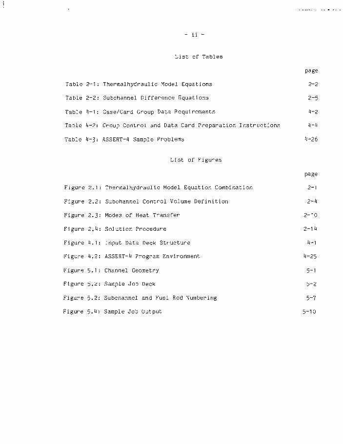
Table 2-1Thermalhydraulic Model Equations
Mixture mass (conservative form)
—- + V-(pV) = 0 (2-1)dt
where p = (ap)v + (ap)^ - ayPv + c P;,
(pV) = (apV)y + (apV)a - pV
Mixture momentum (conservative form)
^ . . „ (ap) (ap) ++ y f p V V +
Mixture energy (transport!ve form)
VP = -F^ + pg (2-2)
P xr + pV-Vh
q "1"- ^-((aq")v + (aq")^)1 (2-31
Phasic energy (transportive form)
- liquid
-v\ <, ^ ( a ^ ) J + q (2H)
vapour
3hy
(ap)y - + (apV)v.Vhv = q-f - ?.(aq«)J + qîf (2-5)
where a + a» = 1
+ - denotes variables that must be defined by state relationships, andt - denotes variables that must be defined by constitutive relationships
Before these equations can be solved numerically, they must be convertedinto appropriate finite difference analogs and closure relationships must be

2 - 3
identified for terms denoted by '+' and 't1, Table 2-1. These closurerelationships, in the form of additional equations, are used to equalize thenumber of definitive equations to the nurrùer of variables rendering the morselequations solvable.
2.2 Subchannel Equations
The finite difference analogs of the •nodel equations presented in Table 2-are derived following the subchannel approach used in the development of theCOBRA-IV[4] computer code.
Following this approach, the model equations are first further simplifiedby retaining only dominant terms. Since transverse flows are assumed smallcompared with axial flows, equation terms dependent on the product oftransverse flowrates are neglected. Unlike COBRA, the transverse gravityterms are retained making it possible to use ASSERT-4 to model the effect ofgravity on horizontal two-phase flows even if the homogeneous option is used.
Next, subchannel control volumes are defined. These control volumes aredefined by dividing the rod bundle into subchannels - subchannels are readilydefined as flow areas between rods bounded by the rods themselves andimaginary lines linking adjacent rod centres - and by further subdividing thesubchannels axially into a number of subchannel control volumes whichcommunicate axially with neighbours in the same subchannel and laterallyacross fictitious boundaries (gaps) with control volumes in neighboringsubchannels. Spatial differenced versions of the model equations are derivedby applying the conservation equations to a representative control volumetaken from subchannel i(k) which shares gap k with an adjacent control volumein subchannel j(k) between axial nodes j-1 and j, Figure 2.2.

3720B
2 -
Figure 2.2Subchannel Control Volume Definition
REACTOR CORE SHOWINGFUEL CHANNELS
CALANDRIA TUBE
GRID SPACERS
END PLATE
SUBCHANNEL
GAP
FUEL CHANNEL SHOWINGFUEL BUNDLE
SUBCHANNEL CONTROLVOLUMES
SUBCHANNEL
DISTANCE,
CENTROID TO CENTROIDSPECIFICATIONS
FUEL BUNDLE SHOWINGSUBCHANNELS
2-5
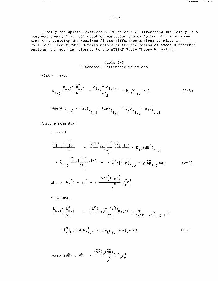
Finally the spatial difference equations are differenced implicitly in atemporal sense, i.e. all equation variables are evaluated at the advancedtime n+1, yielding the required finite difference analogs detailed inTable 2-2. For further details regarding the derivation of these differenceanalogs, the user is referred to the ASSERT Basic Theory Manual[2].
Table 2-2Subchannel Difference Equations
D..W. . = 0 (2 -6 )l k k , j
where p = Cap) + (ap) - a / * a p+
iJ iJ iJ
Mixture momentum
- axial
Mixture
AH .
mass
p i
J
n
i~ P i jAt
F . - F. .
Az.J
{ F U ) i r ( F U ) i i - ii {FU)i r i i i±±A + LlJ 1 > J ' + D (WU )
Az i k v ;
+ + D (WU )At Az . ikv ;k,j
P . .- P.
Ä i i1 t J
* À ( K | F | F ) J - g Âp cose (2-7)
* * (ap ) ( a p ) . » f
w h e r e (WU ) = WU + s — r - ^ 1 U V* r r
- l a t e r a l
W, .- w" . (WÖ), . - (WÛ),D
kAt Az. virk ki i,j-1J
- ( f )k(C|W|w)J ( J - g s^p .^cos^s ine (2-8)
( à p ) ( a p ) _w h e r e (WU) = WU + s „ U V
* r rP

2 -
Mixture energy
h . . - h " . h . . - h . . . f ( a , F ) . . - f ( i , F )iJ iJ i J l J - 1 iJA
n i . J i , J + F i , J l . J 1 + i . Ji , J P i , j At i,j-1 Az Az
J J
( a p ) ( a p )where f ( a , F ) = (h - h . ) A U
v % p r
{2'9)
Phasic Energy
- liquid
- vapour
A. ( a p ) "
h
D., W• 1 vu-
- h ;
At F v .
h —h
Az.»J-1 J
, t
i- D i k(Wh*)
+ - denotes variables that must be defined by state relationships, andt - denotes variables that must be defined by constitutive relationships
To model a given channel, the user must provide data which can be used toevaluate the various terms and coefficients in the subchannel differenceequations, Table 2-2. In addition, to closure relationship information, theuser must provide channel geometry data detailing the geometric relationshipamong the subchannels and fuel rods. The required subchannel data include:
- flow area,- wetted perimeter,- centroid-to-centriod distances and angles,- subchannel connection information,- axial variations in flow and gap spacings, and~ heated perimeter.

2 - 7
The required fuel rod data include:
- average channel heat flux,- axial and radial heat flux distributions, and- adjacent subchannels and fraction of total rod power
input to each adjacent subchannel.
Typical steady-state calculation subchannel and fuel rod data are shown inFigure 5~2 and described in Table 4-2, Card No. 4.1 and 8.1 respectively. Ifthe transient fuel model (Section 3.1) is used, appropriate fuel property dataincluding thermal conductivities and heat capacities must also be provided.
2.3 Closure Relationships
The required closure relationships, as indicated in Tables 2-1 and 2-2,are the equations of state relationships and constitutive relationshipsrelating relative velocity, fluid friction, wall heat transfer, interfacialheat transfer and thermal mixing to primary variables-, phasic flow velocities,densities enthalpies and pressure.
2.3.1 Equation of State
The main purpose of the equation of state in ASSERT is to provide arelation between phasic densities and enthalpies. Other temperature dependentproperties such as thermal conductivity and viscosity must also be related toenthalpy. In Version 1, subcooled liquid properties are assumed to follow thesaturation line and are input in tabular form. Saturation properties areextracted from this table using table look-up based on local subchannelpressure. In the two-phase region, mixture and phasic densities andenthalpies are related by void/quality functions. Superheated steamproperties are available from a table which is prepared internally from steamtable correlations based on the user specified reference pressure. Linearinterpolation is used in all cases to calculate values between table entries.
A typical property table is shown in Figure 5.2. The input variablesare, from left to right, saturation pressure and temperature, liquid andvapour specific volume, liquid and vapour enthalpy, saturated liquidviscosity, thermal conductivity and surface tension (Table 4-2, Card No. 1.1).The user specified reference pressure (Table 4-2, Card No. 11.1) is used tofix the saturation state. If the fluid is single phase, the density andenthalpy determine the state. In the two-phase region, both liquid and vapourdensities and enthalpies are required to calculate void fraction and quality.The viscosity and thermal conductivity are used to compute the Reynolds andPrandtl numbers used in the various correlations. For two-phase conditions,these two properties retain their saturation values.
In the two-phase region, the mixture density is related to the phasicenthalpies in terms of the void fraction-quality relation:
x/p
(i-x)/pt
2 -
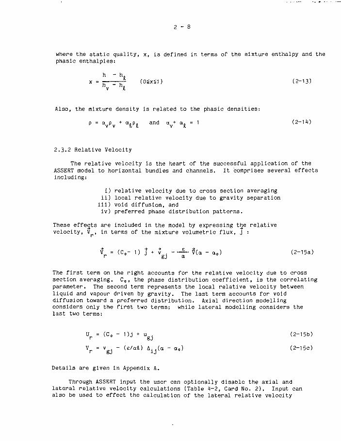
where the static quality, x, is defined in terms of the mixture enthalpy and thephasic enthalpies:
h - hx = rr (05x51) (2-13)h - h.v I
Also, the mixture density is related to the phasic densities:
p = a p + a„p„ and a + an = 1 (2-1v v r i v I
2.3.2 Relative Velocity
The relative velocity is the heart of the successful application of theASSERT model to horizontal bundles and channels. It comprises several effectsincluding:
i) relative velocity due to cross section averagingii) local relative velocity due to gravity separation
iii) void diffusion, andiv) preferred phase distribution patterns.
These effects are included in the model by expressing the relativevelocity, V , in terms of the mixture volumetric flux, j :
Vr = (Co- 1) j + vgj - - £ - $(<x " a0) (2-15a)
The first term on the right accounts for the relative velocity due to crosssection averaging. Co, the phase distribution coefficient, is the correlatingparameter. The second term represents the local relative velocity betweenliquid and vapour driven by gravity. The last term accounts for voiddiffusion toward a preferred distribution. Axial direction modellingconsiders only the first two terms; while lateral modelling considers thelast two terms:
U = (Co - 1)J + u . (2-i5b)
Vp = vgJ - (e/afc) A.j(a - a0) (2-15c)
Details are given in Appendix A.
Through ASSERT input the user can optionally disable the axial andlateral relative velocity calculations (Table 4-2, Card No. 2). Input canalso be used to effect the calculation of the lateral relative velocity

2 - 9
parameters Co and v . (Table 4-2, Card No. 2.1), and the lateral relative
velocity parameters e(Table 4-2, Card No. 10.3) and a0 (Table 4-2,Card No. 10).
2.3.3 Fluid Friction
A distributed resistance concept is used to compute pressure gradientsdue to wall shear and form losses.
The axial losses, represented by the term K|F|F in equation 2-7, arecomputed using the following expression:
K|F|F = ( + ^ ) ( 2 i 6 )2gc ep£ A z p
The first term on the right hand side of this equation represents losses dueto wall friction (shear). The second term represents forms losses due tocomponents such as grid spacers and bundle end-plates appearing in theinterval Az (Table 4-2, Card No.'s 7 and 7.2).
In ASSERT-4, the single-phase friction factor, f, is computed from one ofthe following:
i) f = a Reb + c
ii) the Colebrooke equation[6] which approximatesthe Moody diagram.
The choice is left to the user (Table 4-2, Card No. 2). If he chooses thefirst approach, he must supply data which fix the coefficients a, b and c(Table 4-2, Card No. 2.1). If he chooses the second, he must supply therelative roughness (Table 4-2, Card No. 2.2).
ASSERT-4 contains several options for computing the two-phase frictionmultiplier, <j>2:
i) homogeneous (<J>2 = Pç/p)ii) Armand correlation[7], andiii) user specified polynomial in quality.
Again the choice is left to the user (Table 4-2, Card No. 2).
Lateral losses, represented by the C|W|W term in equation 2-8, arecomputed in a similar fashion:
c l w l w = 2 ^ " ^ (2-17)c p
In this relationship frictional losses are lumped in with the form losses andrepresented by the lateral loss coefficient, K. In ASSERT this value is asingle constant which by default is 0.5 (Table 4-2, Card No. 9.2).

2 - 1 0
2.3.4 Heat Transfer and Heat Transfer Coefficients
The heat transfer model is based on the assumptions that heat istransferred from the fuel rod surface (wall) to the coolant in adjacentsubchannels and between phases when the flow is two-phase. This heat transfermodel has five components:
1) the wall-to-liquid component, q' .,
2) the wall-to-vapour component, q'wv
3) the wall-to-interface component, q' .,
*)) the interface-to-liquid component, q'..,
5) the interface-to-vapour component, q'.and
as illustrated in Figure 2.3. It is further assumed that these components arerelated to heat transfer coefficients as follows:
q' = H A1 (T - T)r
(2-18)
where q' = heat transferredH = heat transfer coefficientA' = heat transfer surface area per unit length of
subchannelT = reference temperatureT =••= the bulk fluid temperature.
Using this model combined with the phasic energy equations, equations 2-10 and2-11, makes it possible to model the thermal non-equilibrium effects of sub-cooled boiling, boiling transition (dry-out), condensation and flashing.
Figure 2.3Modes of Heat Transfer
INTERFACE
-h. LiaUID
1'wv 'IIlh—-Pit
VAPOUR W
2-11
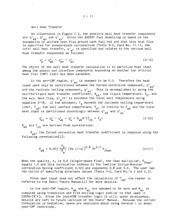
Wall Heat Transfer
As illustrated in Figure 2.3. the possible wall heat transfer componentsare q' , q1 and q' .. Since the ASSERT fuel modelling is based on the
assumption of uniform heat flux around each fuel rod and that this heat fluxis specified for steady-state calculations (Table -M—2, Card No. 11.1), thetotal wall heat transfer, q' , is specified and related to the various wall
heat transfer components as follows:
q' - q'- + q' + q' (2-19)W W)£ WV Wl
The object of the wall heat transfer calculation is to partition heat inputamong the phasic and interface components depending on whether the criticalheat flux (CHF) limit has been exceeded.
In the pre-CHF region, q' is assumed to be 0.0. Therefore the heat
input need only be partitioned between the forced convection component, q' .,
and the nucleate boiling component, q' .. This is accomplished by using the
wall-to-liquid heat transfer coefficient, H . , the liquid temperature, T., and
the wall heat flux, q' /A' to estimate the local wall temperature using
equation 2-18. If the estimate^ T. exceeds the nucleate boiling temperatureJO
limit, T , the wall surface temperature, T , is limited to T and the total
heat input is partitioned accordingly between q1 . and q1 .:WJ6 W1
H . and T , are derived from correlations,wil nb
H , the forced convection heat transfer coefficient is computed using the
following correlation[2]:
Hw, = 0.023 (^) (Re (1-x))0-8 P r ° ^ F C h e n (2-21)
When the quality, x, is 0.0 (single-phase flow), the Chen multiplier, F ,equals 1.0 and this correlation reduces to the familiar Dittus-Boeltercorrelation having coefficient 0.023 and exponents 0.8 and 0.4. The user hasthe option of specifying alternate values (Table 4-2, Card No.'s 2 and 2.3).
Since user input does not affect the calculation of T , the reader isreferred to the Basic Theory Manual[2] for more details.
In the post-CHF region, H and H . are assumed to be zero and H is
computed using transition and film boiling logic similar to that used inCOBRA-IV[4], Since the post-CHF transfer logic is still under development,details are left to future versions of the Users' Manual. Because the currentformulation is tentative, users are cautioned about using Version 1 to modelpost-CHF conditions.

2 - 1 2
Interfacial Heat Transfer
Analysis of heat transfer at the interface is based on the interfacialenergy balance:
%i + "i* + <>iv + A l ^ ( h v _ -h,_) = 0 (2-22)
The wall contribution, q'., is determined by analysis of the wall heat
transfer described previously. The interfacial heat transfer rates, q' andq! , equations 2-10 and 2-11» are determined from the following:
«ik = HikAi(Tsat - V ' k " *"v (2~23)
where the saturation temperature represents the temperature at the interface.To compute the interfacial heat transfer rates, correlations for H.., H. andA! are used.
Since the user is not required to select interface heat transfercoefficient options, and since Version 1 correlations are tentative, detailsare left to a future version of the Users' Manual. Suffice to say, that inthe final version, a flow regime dependent approach to the calculation ofthese parameters will be implemented.
2.3.5 Thermal Mixing
Thermal mixing, represented by the D (aq') terms in equations 2-11, 2-12and 2-13, Table 2-2, are defined by analogy with turbulent diffusion. Forsubchannel pair, i(k) and j(k), the liquid thermal mixing is represented by:
(aq') = -sk(ap£) ( J(k), ^ ) = WI ( h - h ) (2-24)\ k \ k j(k) i(k)
where e = the turbulent diffusivity for the given subchannel pair, and
W' can be written in dimensionless form:
U De
(2-25)
In this form, W . is a inverse function of Peclet number, Pe. For single-phase

13
flow, the Peclet number can be correlated with the Reynolds number[4]. Thisrelationship is assumed to apply to two-phase mixtures, thus:
( 2- 2 6 )
A similar relationship is defined for the vapour phase.
Through ASSERT input, the user fixes the phasic thermal mixingcorrelation parameters a and b for bare rods and end-plates (Table 4-2,Card No.'s 10, 10.1 and 10.2).
2.4 Solution Procedure
The solution procedure uses a combination of iteration and directsolution as shown in Figure 2.3. The channel is successively swept from theinlet to the exit. This outer iteration continues until convergence isachieved or urtil an iteration limit is reached. Successful completion wouldyield a steady-state solution or one time-step of a transient solution.
The numerical solution over the bundle cross section at each axialposition is split into two parts. The first part solves the energy and stateequations. This is done by using a block iterative method to calculate themixture and phasic enthalpies for all subchannels where current flow estimatesare used as parameters. Once the energy equation solution, inner iteration,converges, the second part calculates the flows and pressure gradients at thataxial position. This is done by the direct matrix solution of the crossflowequations from which it is possible to calculate axial flows and pressuregradients. Both parts are repeated once to ensure a higher level ofconvergence of both energy and flow solutions prior to moving to the nextaxial position.
The user controls this calculation process by fixing termination criteriafor both the inner and outer iteration loops (Table 4-2, Card No. 9.1). Theinner loop calculation is stopped when either the maximum absolute error incomputed subchannel enthalpy is less than some specified value or after aspecified maximum number of iterations is exceeded. Similarly, the outer loopiteration is terminated when the relative local flow error is less than somespecified value or a specified maximum number of iterations is exceeded.

2 - 1 4
Figure 2.4Solution Procedure
)
±Set B. C.
Energy SolutionFor each Subchannel
Calculate: h, hl, hv, a
Yes
Flow SolutionCalculae: F, W, Px
| Outer_Loop

3 -
3. Auxil iary Models and _C al c ul a t j_ons
3.1 Fuel Model
The fuel model in ASSERT computes internal temperature distributionswithin fuel and cladding, and can be used to include the effects of axialconduction and temperature dependent fuel conductivity. This model isidentical to the one used in COBRA-IV[3]. Note that although this model isavailable, it has yet to be fully tested and the preferred method of usingASSERT Version 1 is with a constant heat flux boundary condition.
3.2 Header-to-header Model
(This space is reserved for a header-to-header model description. Version1 does not have an operational header-to-header model; later versions willhave this feature.)
3.3 Critical Heat Flux (CHF) Calculations
Critical heat flux (CHF) is defined as that condition under which a smallincrease in heat flux gives rise to a boiling crisis, or an inordinatedeterioration in the heat transfer from a surface. In ASSERT, the criticalheat flux is computed using either the Westinghouse W~3 correlation[8], or theWhalley mechanistic model[9] (Table H-2, Card No. 8).
The characteristic parameter used in W~3 CHF analysis is the CriticalHeat Flux Ratio (CHFR), the ratio of the critical heat flux at a givenlocation to the actual heat flux at that location. CHF occurs whe^ this ratiois 1.0. CHFR's greater than 1.0 indicate that CHF has not yet occurred andthe minimum CHFR, if greater than 1.0, provides a measure of the channelthermal margin.
When the Whalley model is used the location at which CHF occurs(subchannel, axial node and fuel rod) is identified. Because of the nature ofthe Whalley approach, it is impractical to calculate CHFR's.
4 - 1
'A• Using ASSERT-4
Before using ASSERT-4 co model flow and heat transfer in a specific rodbundle arrangement, the user must prepare an input data deck similar to theone illustrated in Figure 5.2. The data contained in this deck are read byASSERT and used to fix thermodynamic and physical property data, to describebundle geometry, to selerc thermal-hydraulic model options, to fix boundaryconditions and to set calculation control parameters.
This section contains not only a detailed description of user input datarequirements, but also information describing how to access and run ASSERT-4on the Chalk River computers.
4.1 User Input Data Description
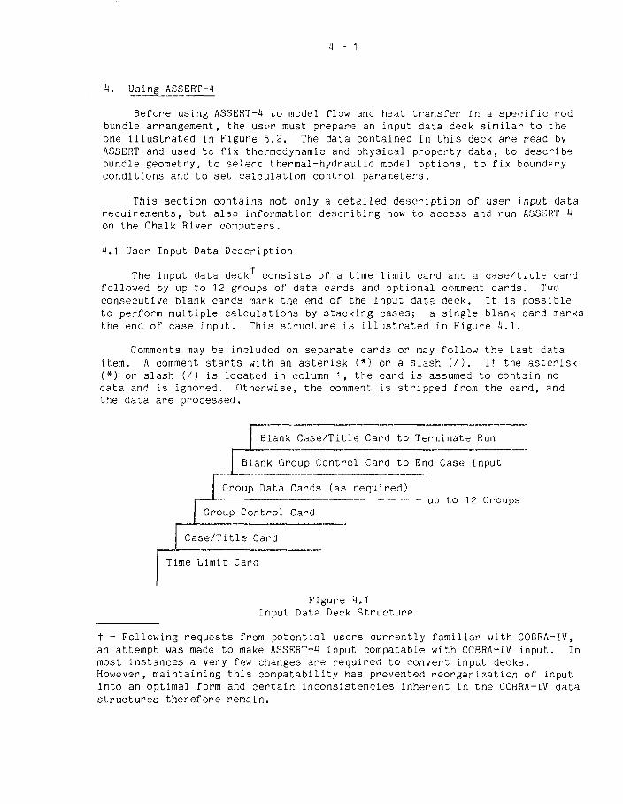
The input data deck consists of a time limit card and a case/tide cardfollowed by up to 12 groups of data cards and optional comment cards. Twoconsecutive blank cards mark the end of the input data deck. It is possibleto perform multiple calculations by stacking cases; a single blank card marksthe end of case input. This structure is illustrated in Figure 4.1.
Comments may be included on separate cards or may follow the last dataitem. A comment starts with an asterisk (*) or a slash (/). If the asterisk(*) or slash (/) is located in column 1, the card is assumed to contain nodata and is ignored. Otherwise, the comment is stripped from the card, andthe data are processed.
Blank Case/Title Card to
Blank Group Control Card to
Group Data
Group Control
Case/Title Card
Time Limit Card
Cards (as required)
Card
Terminate
End Case
— up to 1
Run
Input
2 Groups
Figure 4.1Input Data Deck Structure
t - Following requests from potential users currently familiar with COBRA-IV,an attempt was made to make ASSERT-4 input compatable with COBRA-IV input. Inmost instances a very few changes are required to convert input decks.However, maintaining this compatability has prevented reorganization of inputinto an optimal form and certain inconsistencies inherent in the COBRA-IV datastructures therefore remain.
- 2
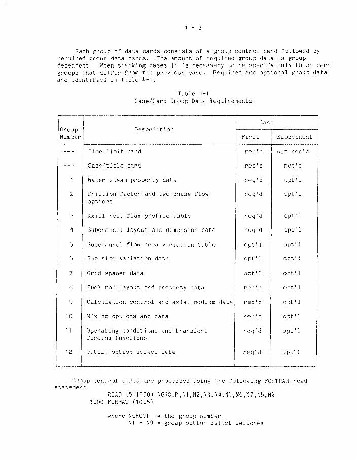
Each group of data cards consists of a group control card followed byrequired group data cards. The amount of required group data is groupdependent. When stacking cases it is necessary to re-specify only those caragroups that differ from the previous case. Required and optional group dataare identified in Table 4-1.
Table 4-1Case/Card Group Data Requirements
GroupNumber
1
2
3
H
b
6
7
8
9
10
11
12
Description
Time limit card
Case/title card
Water-steam property data
Friction factor and two-phase flowoptions
Axial heat flux profile table
Subchannel layout and dimension data
Subchannel flow area variation table
Gap size variation data
Grid spacer data
Fuel rod layout and property data
Calculation control and axial nodiig data
Mixing options and data
Operating conditions and transientforcing functions
Output option select data
Case
First
req'd
req 'd
req'd
req'd
req 'd
req'd
opt'l
opt'l
opt' 1
req'd
req'd
req ' d
req r d
,-eq'd
Subsequent
not req'd
req 'd
opt'l
opt'l
opt'l
opt'l
opt'l
opt'l
opt'l
opt'l
opt'l
opt' 1
opt' 1
opt' 1
Group control cards are processed using the following FORTRAN readstatement:
RFAD (5,1000) MGR0UP.N1,N2,N3,N4,N5,N6,N7,N8,N91000 FORMAT (1015)
where NGROUP = the group numberNI - N9 = group option select switches

1 - 3
Group option select switches and data card formats and preparationinstructions are presented in Table 1-2. This table contains card numberidentifiers, input variable names and formats, descriptions.
The card numbers, column 1, Table 1-2, are assigned to uniquely identifyeach group control card and related data cards. Group control cards areassigned integer numbers; related data cards have an additional fractionalpart. These numeric identifiers reflect the required input order and theorder the data are processed by ASSERT-1.
Input variable names and formats are presented in column ?., Table 1-2.The variable names are the same as used in coding ASSERT-1. The formats arethe FORTRAN READ statement formats used in ASSERT-1 to direct input processingof the associated data.
Descriptions of group control and data card data are presented incolumn 3i Table 1-2. Criteria for including optional group data and defaultvalues are included in these descriptions.
Default values are assigned to many input parameters. These values areused when the corresponding input field is blank. Since most parameters withdefault values affect the "stability" of the solution, it is recommended thatthe default value be used until the user is familiar with each parameter.
The following input data preparation instructions are presented to act asa guide for those who must use ASSERT-1 Version 1. Due to the aforementionedmandate to retain compatability with COBRA-IV, the COBRA-IV input formats havebeen retained, however group control card and data preparation instructionsfor several infrequently used COBRA options have not been included inTable 1-2. These descriptions were not included because the options theyinvoke are presently inactive. Exceptions to this are the transientcalculation data (Groups 9 and 11) and the fuel model transient calculationdata (Group 8). These descriptions have been included but as mentioned inSection 1 the options they invoke have not been fully tested.

TABLE k-2GROUP CONTROL AND DATA CARD PREPARATION INSTRUCTIONS
Card No
—
1
Variables and Fermât
MAXT
FORMAT (15 )
KASE,J1,TEXT
FORMAT ( 2 I 5 . 1 7 A 4 )
ŒOUP 1 WATER-STEAM PROPERTY TABLE
FORMAT (1015)
(Fer additional information related tothis card group refa-* to Section 2.3.1)
Description
Must be the first data card of the input deck. Input only once.
MAXT = The computer time limit (sec) allowedfcr problem calculations. Computer CPtime limit must be greater than MAXT.
Cass control card, where:
KASE = Problem case number.K > 0, begin new case.K = 0, STOP.
J1 = Print option for input data.J1 = 0, print only new input data.J1 = 1, print all input data.J1 = 2, print only operating conditions.J1 =10, print all input data, then stop.
TEXT = Output text fcr problem identification,maximum 68 characters.
N1 = NPROP, nunber of property cards to be read.N2 = ISTEAM, superheated steam option select parameter:
N2 = 0, superheated steam properties are not usedN2 = 1, superheated steam properties are calculated
and usedN3 = Superheated steam property range (ignored if N2=0):
N3 = 0, code calculates superheated steam propertiesfrcm saturation to 1500 °F
N3 = 1, code computes N1 properties over thetemperature range specified by DTMAX(Card No 1.2)
I

TABLE l)-2 (cont'd)GROUP CONTROL AND DATA CARD PREPARATION INSTRUCTIONS
Card No
1.1
1.2
2
Variables and Format
PP(I),TT(I),WF(I),WG(I)>HHF(I),HHG(I),UUF(I),KKF(I),SSIOMA(I) (1 = 1 toN1)
F0RMAT(F5.2,F5.1,7F10.0)
DTMAX
FORMAT ( F 5 . 3 )
GROUP 2 FRICTION FACTORS AND TW3 PHASEFLOW OPTIONS
FORMAT (1015)
(Fer additional information related tothis card group refer to Sections 2.3.2,2.3-3, 2.3.1 and Appendix A)
Description
Read in NI saturated liquid and vapor property cards, where:
PP = System pressure (psia)TT = Temperature (°F)WF = Liquid specific volune (ftVlb)WG = Vapor specific volune (ftVlb)HHF = Liquid enthalpy (Btu/lb)HHG = Vapor enthalpy (Btu/lb)UUF = Liquid viscosity (lb/ft-hr)KKF = Liquid thermal conductivity (Btu/hr-ft-°F)SSIGMA = Surface tension (lbVft)
Optional Input - N2 = 1 and N3 = 1
DTMAX = The temperature range over which thesuperheated steam properties are to becalculated. DTMAX = (T-T ), where T isis the desired maxiraun temperature and Tis the saturation temperature.
N1 = Thermal modelling option select parameter.N1 = 0, thermal equilibrium.N1 = 1, liquid thermal non-equilibrium.N1 = 2, vapor thermal non-equilibirum.N1 = 3, liquid and vapor thermal non-equilibriun.
N2 = NFRIC, Turbulent friction factor option selectparameter.N2 = 0, turbulent friction factor is of the
fcrm: f = a Reb + c (Card No 2.1)N2 = 1, tirbulent friction factor is conputed
using the Colebrook equation (Card No 2.2)N3 = NMJLT, Two-phase friction multiplier option select

TABLE 4-2 (cont'd)GROUP CONTROL AND DATA CARD PREPARATION INSTRUCTIONS
Card No Variables and Format Description
2.1 AA(I),BB(I),CC(I) (I = 1 to 4)
FORMAT (12F5.3)
parameter.N3 = 0, homogeneous model.N3 = 1, Armand model.N3 > 4, read in number of terms and coefficients for
up to 6th order polyncmial function of thetwo-phase multiplia" versus quality.
N3 = 8, Lcrene-Leung correlation without subcooling.N4 = (not used)N5 = (not used)N6 = Rod-to-coolant single phase heat transfer
coefficient option select parameter.N6 = 0, Dittus-Boelter correlation used.N6 > 0, read a user-supplied correlation.
N7 = NGRAV, T r a n s v e r s e momentun e q u a t i o n g r a v i t y termopt ion s e l e c t parameter.N7 = 0, no g rav i t y t e rms .N7 = 1, include g r a v i t y terms.
N8 = NUREL, Axial r e l a t i v e v e l o c i t y op t ion s e l e c tparameter.N8 = 0, no axial relative velocity.N8 = 1, include axial relative velocity option
and coefficients (Card No 2.6).N9 = NVREL, La te ra l r e l a t i v e ve loc i ty opt ion s e l e c t
parameter.N9 = 0, no lateral relative velocity.N9 = 1, include lateral relative velocity option
and coefficients (Card No 2.7).
Optional input - N2=0
Turbulent friction factor coefficients.
AA,BB,CC = the constants of the correlation in the
i
ON

TABLE Ü-2 (cont'd)GROUP CONTROL AND DATA CARD PREPARATION INSTRUCTIONS
Card No
2.2
2.3
2. it
2.5
Variables and Format
EPODC
FORMAT (F10 .0)
AH(I) (I - 1 t o it)
FORMAT (12E5.0)
NF.AF(I) (I = 1 to 7)
FORMAT (15, 7E1O.5)
AUR(I) (I = 1 to Ü)
FORMAT (12F5.3)
Description
RR
form f = AA(Re) + OC. Read one set fcreach of up to it subchannel types.
Optional input - N2=1
EPODC = Colebrook turbulent friction factor correlationrelative roughness (Default: 0.0)
Optional Input - N6 > 0
AH = Coefficients for a single phase heattransfer correlation of the form:
h = (K/D) (AH(1)Re Pr 3 + AH(i|))For N6 < 0, AH(I) defaults to 0.023, 0.8,0.1 and 0.0 fcr AHO) through AH(it),respectively.
Optional Input - N3 > k
Two phase friction multiplier, where:
NF = The nunber of terms for the polyncmialfunction of quality.
AF = Constants fcr up to 6th crder polynomialfunction of the two-phase friction multi-plier versus steam quality.
Optional Input - N8 = 1
Axial relative velocity coefficients, where:
AURO) = (not used but card required)
I

TABLE 4-2 (cont'd)GROUP CONTROL AND DATA CARD PREPARATION INSTRUCTIONS
Card No
2.6
3
3-1
4
Var iab les and Format
AVR(I) (I = 1 t o 4)
FORMAT (12F5.3)
GROUP 3 AXIAL HEAT FLUX PROFILE TABLE
FORMAT (1015)
Y(I),AXIAL(I) (1 = 1 t o N 1 )
FORMAT (12F5.3)
GROUP 4 SUBCHANNEL LAYOUT AND DIMENSION DATA
FORMAT (1015)
(For additional information related tothis card group refer to Sections 2.2)
Description
Optional Input - N9 = 1
Lateral relative velocity coefficients, where:
AVR(1) = k l t the leading coefficient fcr v^,Appendix A, equation A-17. (Recoramended: 2.)
AVR(2) = m, Ohkawa-Lahey multiplier exponent,Appendix A, equation A-25. (Recaimended: 1.5)
N1 = NAX, nunber of entries in heat flux table.
Axial heat flux table, where:
Y = Relative position (z/L) at which heat flux isgiven, where L is the bundle total length of thebundle. Must include 0.0 and 1.0 as end points.
AXIAL = Relative heat flux at (z/L). (local flux/average flux).
Note: This Card Group may not be needed depending on the CardGroup 9, N7 options.
NI = Number of data cards of subchannel informationto be read. One card for each subchannel,unless already assigned (e.g. multicase run).
N2 = Total number of subchannels, regardless of NI.

TABLE 4-2 (cont'd)GROUP CONTROL AND DATA CARD PREPARATION INSTRUCTIONS
Card No
4.1
5
Variables and Format
[N,I,AC(I),PW(I),PH(I),[LC(I,L),GAPS(I,L),DIST(I,L),DEG(I,L), L = 1 ,3 ] , I = 1,N1]
FORMATU1,14,3F5.2,3(I5,3F5.2))
GROUP 5 SUBCHANNEL FLOW AREA VARIATION TABLE
FORMAT (1015)
Descript ion
N = Subchannel type . I f blank or zero , type 1 i sassigned. I f CKN^), type N i s ass igned.The subchannel type i nd i ca t e s theappropriate friction factor correlationsto be used. (Card No 2.1 and 2.2).
I = Subchannel identification number.AC = Nominal subchannel area (in2).PW = Nominal subchannel wetted perimeter (in).PH = Nominal subchannel heated perimeter (in).LC = Adjacent subchannel identification number fcr up to
3 subchannels adjacent to subchannel I . Subchanneldata are input with ascending identificationnumbers. Only connections LC(I,L) > I are read in.For connections coincident with a line of symmetry,LC(I,L) is input as a negative number.
GAPS = The nominal GAP width between subchannel I andthe adjacent subchannel specified by LC (in).
DIST = Centroid-to-centroid distance between theadjacent subchannels specified by LC (in).
DEG = Angular crientation of gap connection usingcompass coordinates. 0° is vertical upwardfor a horizontal channel.
Note: I t is important that the centroid-to-centroid distances(DIST(I,L)) and angular orientation of the gap angle(DEG(I,L)) be accurately defined.
NI = NAFACT, nimber of subchannels for whicharea variation tables are to be read.
N2 = NAXL, nunber of axial locations fcr sub-channel area variation.
N3 = NARAMP, the nunber of iterations fcr gradual
.tr
IVD

TABLE H-2 (cont'd)GROUP CONTROL AND DATA CARD PREPARATION INSTRUCTIONS
Card No
5.1
5.2
6
6.1
Variables and Format
AXL(I) (I = 1 t e N2)
FORMAT (12F5.3)
[I,(AFACr(L,J), L = 1.N2), J = 1.N1]
FORMAT (I5/C12F5.3))
GROUP 6 GAP SIZE VARIATION TABLE
FORMAT (1015)
GAPXL(L) (L = 1 to N2)
FORMAT (12F5.3)
Description
insertion of area var ia t ions . If blank orzero, NARAMP = 1.
Table of axial locations, where:
AXL = Axial location (z/L) where subchannel areavariations wil l be specified. Read in N2values which apply to a l l subchannelsspecified in Card No 5 .2 .
For NI subchannels read flow area variat ion factors a t N2 axiallocations corresponding to (AXL), where:
I = Identif icat ion number of a subchannel forwhich area variations are being specified.Read according to (15) format, then skipt o the next card and read a complete setof factors (AFACT) corresponding t o theAXL locations. Repeat unt i l factors fcrNI subchannels are read.
AFACT = Relative subchannel area (Ai/k
ranimi')
at each axial level (AXL).
NI = NGAPS, nunber of GAPS for which GAPvariation tables are to be read.
N2 = NGXL, nunber of axial locations for GAPvariat ion.
Table of axial locations, where:
GAPXL = Axial locations (z/L) where GAP variat ionswil l be specified. Read N2 values whichapply to a l l GAPS K specified in Card No 6.2.
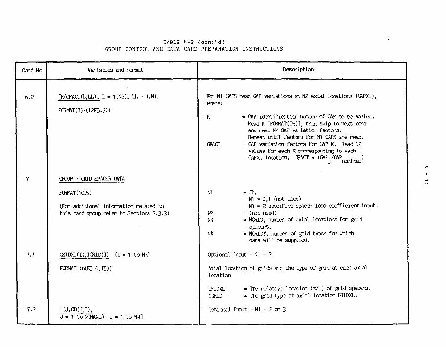
TABLE i»-2 (cont'd)GROUP CONTROL AND DATA CARD PREPARATION INSTRUCTIONS
Card No
6.2
7
7.1
7.2
Variables and Format
[K(CFACT(L,LL), L = 1,N2), LL = 1 ,N1 ]
FCRMIVr(I5/(12F5.3))
CROUP 7 GRID SPACER DATA
FORMAT(1OI5)
(Fer addit ional information re la ted t ot h i s card group refer t o Sections 2.3.3)
GRIDXL(I),IGRID(I) ( I = 1 t o N 3 )
FORMAT (6(E5.0,I5))
[(J,CD(J,I),J = 1 to NCHANL), I = 1 t o W]
Description
Fcr N1 GAPS read GAP variations at N2 axial locations (GAPXL),where:
K = GAP identification nunber of GAP to be varied.Read K [FCRMAT(I5)], then skip to next cardand read N2 GAP variation factors.Repeat until factors for N1 GAPS a^e read.
GFACT = GAP variation factors fcr GAP K. Read N?values fcr each K corresponding to eachGAPXL location. GFACT = (G A P - / G f t p
r a n i n a l )
N1 = J6.N1 =0 ,1 (not used)N1 = 2 specifies spacer loss coefficient input.
N2 = (not used)N3 = NCRID, nunber of axial locations fcr grid
spacers.nH = NGRIDT, nunber of grid types for which
data will be supplied.
Optional Input - N1 = 2
Axial location of grids and the type of grid at each axiallocation
GRIDXL = The relative location (z/L) of grid spacers.IGRID = The grid type at axial location GRIDXL.
Optional Input - N1 = 2 or 3
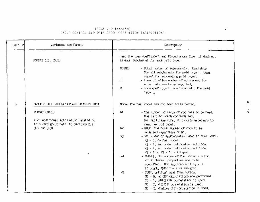
TABLE H-2 (cont'd)GROUP CONTROL AND DATA CARD PREPARATION INSTRUCTIONS
Card No
8
Variables and Format
FORMT (15, E5.2)
GROUP 8 FUEL ROD LAYOUT AND PROPERTY DATA
FORMAT (1015)
(For addi t ional information re la ted t othis card group refer to Sections 2.2,3.1 and 3-3)
Description
Read the loss coefficient and forced cross flow, if desired,in each subchannel for each grid type.
NCHANL = Total nunber of subchannels. Read datafcr all subchannels for grid type 1, thenrepeat fcr succeeding grid types.
J = Identification nunber of subchannel fcrvfrùch data are being supplied.
CD = Loss coefficient in subchannel J fcr gridtype I.
Note: The fuel model has not been fully tested.
N1 = The nunber of cards of rod data to be read.One card fcr each rod modelled.For multicase runs, i t is only necessary toread new rod input.
N2 = NROD, the total number of rods to bemodelled regardless of NI.
N3 = NC, order of approximation used in fuel model.N3 = 0, no fuel model.N3 = 2, 2nd orda- collocation solution.N3 = 3, 3rd order collocation solution.N3 > 3 or N3 = 1 is illegal.
Nil = NFUELT, the nunber of fuel materials fcrwhich thermal properties are to bespecified. Not applicable if N3 = 0.If blank, NFUELT = 1 is assigned.
N5 = NCHF, critical heat flux option.N5 = 0, no CHF calculations are performed.N5 = 1, BAW-2 OF correlation is used.N5 = 2, W-3 CHF correlation is used.N5 = 3, Whalley CHF correlation is used.
-tr
(
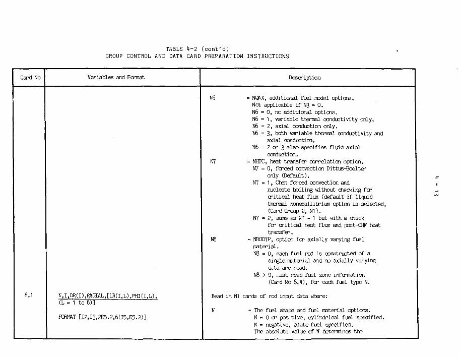
TABLE 4-2 (cont'd)GROUP CONTROL AND DATA CARD PREPARATION INSTRUCTIONS
Card No
8.1
Variables and Format
N,I,DR(I),RADIAL,[LR(I,L),PHI(I,L),(L = 1 to 6)]
FORMAT [I2,I3,2E5.2,6(I5,E5.2)]
Description
N6 = NQAX, additional fuel model options.Not applicable if N3 = 0.N6 = 0, no additional options.N6 = 1, variable thermal conductivity only.N6 = 2, axial conduction only.N6 = 3, both variable thermal conductivity and
axial conduction.N6 = 2 or 3 also specifies fluid axial
conduction.N7 = NHTC, heat transfer correlation option.
N7 = 0, forced convection Dittus-Boelteronly (Default).
N7 = 1, Chen forced convection andnucleate boiling without checking fcrcritical heat flux (default if liquidthermal nonequilibriun option is selected,(Card Group 2, N1 ).
N7 = 2, same as N7 = 1 but with a checkfcr critical heat flux and post-CHF heattransfer.
N8 = NRODTP, option fcr axially varying fuelmaterial.N8 = 0, each fuel rod is constructed of a
single material and no axially varyingcL.ta are read.
N8 > 0, ...ust read fuel zone information(Card No 8.4), fcr each fuel type N.
Read in NI cards of rod input data where:
N = The fuel shape and fuel material options.N = 0 cr pos. tive, cylindrical fuel specified.N = negative, plate fuel specified.The absolute value of N determines the
I
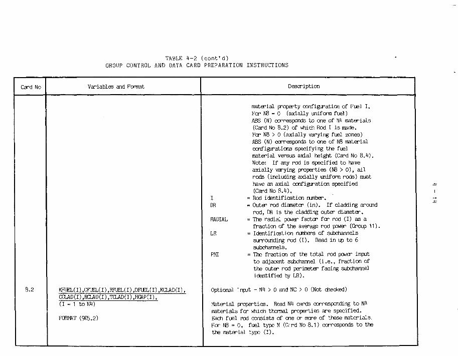
TABLE il—2 (cont'd)GROUP CONTROL AND DATA CARD PREPARATION INSTRUCTIONS
Card No Variables and Format Description
8.2 KFUEL(I),CFUEL(I),RFUEL(I),DFUEL(I),KCLAD(I),CCLAD(I),RCLAD(I),TCLAD(I),HGAP(I),(1 = 1 to Nit)
FORMAT (9E5.2)
material property configuration of Fuel I.For N8 = 0 (axially uniform fuel)ABS (N) corresponds to one of N4 materials(Card No 8.2) of which Rod I i s made.Fer N8 > 0 (axially varying fuel zones)ABS (N) ccrresponds to one of N8 materialconfigurations specifying the fuelmaterial versus axial height (Card No 8.4).Note: If any rod is specified to haveaxially varying properties (N8 > 0) , al lrods (including axially unifcrm rods) musthave an axial configuration specified(Card No 8.4).
I = Rod identification number.DR = Outer rod diameter ( i n ) . I f c ladd ing around
r o d , DR i s t he c ladding ou te r d i ame te r .RADIAL = The radial power factcr for rod (I) as a
fraction of the average rod power (Group 11).LR = Ident i f icat ion numbers of subchannels
surrounding rod ( I ) . Read in up t o 6subchannels.
PHI = The fraction of the to t a l rod power inputt o adjacent subchannel ( i . e . , f ract ion ofthe outer rod perimeter facing subchannelidentified by LR).
Optional Input - NI > 0 and NC > 0 (Not checked)
Material propert ies . Read N4 cards corresponding to N4mater ia ls for which thermal properties a re specified.Each fuel rod consists of one or mere of these materials .For N8 = 0, fuel type N (frrd No 8.1) ccrresponds t o thethe material type ( I ) .

TABLE k-2 (cont'd)GROUP CONTROL AND DATA CARD PREPARATION INSTRUCTIONS
Card No
8.3
8.1)
Variables and Format
TREF.BKd), (I = 2 to k)
FORMAT (F10.0, 3E1O.4)
[NZONE(I),(ZE>JD(I,K),IZTYP(I,K),K = 1 to NZONE(I)), I = 1 toN8]
FORMAT (I5/(6(E5.2,I5)))
Description
KFUEL = The thermal conductivity of the fusl(Bti>'"r-ft~°F).
CFUEL = Specific heat of fuel (Btu/lb-°F).RFUEL = Fuel density ( lb / f t 3 ) .DFUEL = The fuel diameter ( in) .KCLAD = Thermal conductivity of cladding
(Btu/hr-f t - °F) .CCLAD = Specific heat of clad (Btu/lb-°F)RCLAD = Density of cladding ( l b / f t 3 ) .TCLAD = Cladding thickness ( in ) .HCAP = Fuel-Clad Gap conductance coefficient
(Btu/hr-ft2-°F).
Optional Input - NC > 0, and NQAX = 1 or 3 (Not checked)
Variable thermal conductivity. Only applies to the materialspecified by the f i r s t card of Card No 8.2.
TREF = The reference temperature, where :K = KFUELO) (°F)
BK = The coefficients fcr up to 3rd orderpolynomial approximation for thermalconductivity versus temperature of theform:K(I) = KFUEL(l) * [1 + BK(2) * (T - TREF)
+ BK(3) (T - TREF)2 - BKW(T - TREF)3]
Optional Input - N8 > 0 (Not checked)
Option to specify axially varying fuel nHterials. Must readin a fuel zone configuration table fcr each rod type N(Card No 8.1).

TABLE il—2 (cont'd)GROUP CONTROL AND DATA CARD PREPARATION INSTRUCTIONS
Card No
9
Var iab les and Format
GROUP 9 CALCULATION CONTROL ANDAXIAL NODING DATA
FORMÂT (10I5)
(Fer additional information related toth is card group refa" to Sections 2.3.3,and 2.6)
Description
NZCNE = The nunber of axial zones to be read fer atable of fuel material versus axial distance.for fuel type I .
ZEND = Relative axial location (X/L) of the endof a fuel zone. If fuel type I i s axiallyuniform, ZEND(I,1) = 1.0.
IZTYP = Type of material in fuel zone ending a tZEMD. Each IZTYP corresponds to amaterial specified in Card No 8.2. Onlymaterial type 1 can have variable thermalconductivity.
N1 = NSKIPX, output print option.N1 = 0 or 1, print for a l l axial nodes.NI > 1, print every N1 axial nodes.
N2 = N3KIPT, output print option.N2 = 0 or 1, print a l l time steps.N2 > 1, print every N2 time steps.(Transient option not checked out) .
N3 = (not used)M = (not used)W5 = (not used)N6 = ND>3DPT, option for axial noding.
N6 = 0, uniform axial node length.N6 = 1, variable axial node length (Card No 9.3)N6 = 2, CANDU assemblies (Card No 9.4)
N7 = NQXOPT, option fcr axial power profi le.N7 = 0, use Card Group 3 to calculate
nodal power factors .N7 = 1, read in nodal power factors.
(Card No 9.5)N7 = 2, read in CANDU bundle axial power
factors. (Card No 9.6)

TABLE 4-2 (cont'd)GROUP CONTROL AND DATA CARD PREPARATION INSTRUCTIONS
Card No
9.1
9.2
9.3
9.4
V a r i a b l e s and Format
NTRIES, IELIMT, HERROR, EERROR, FERROR, TT IM», NDT
FORMAT(215,4E5.0,15)
Z.NDX,THETA,KIJ
FORMAT (E5 .0 . I5 .12E5 .0 )
IDNODE(J),X(J+1) (J=1,NDX)
FORMAT ( 6 ( 1 5 , E 5 . 2 ) )
NASSYS, ASS YL, ASS YHL,NHTDX
Description
NTRIES = The maximun number of external iterationsallowed regardless of FERROR. (Default: 20)
IELIMT = The maximun number of energy solutioniterations regardless of HERROR. (Default: 10)
HERROR = The enthalpy errcr criteria (Btu/lb).(Default: 0.01)
EERROR = The energy errcr criteria (Btu/sec-ft).(Default: 0.01) (not used)
FERROR = The external axial flow convergence limit.If relative flow error, AF/F, is greater thanFERROR, another iterative sweep of the entirebundle is made. (Default: 0.01)
TTIM2 = The total transient time (sec).NDT = The total number of time steps allowed.
The time step size is (TTIME/NDT).
Z = The total axial length (in.).NDX = The nunber of axial nodes.THETA = The bundle orientation (degrees):
0., or blank = vertical,90. = horizontal.
(Default: 0., vertical)KIJ = The crossflow (lateral) loss coefficient.
(Default: 0.5)
Optional input N6=1
IDNODE(J) = The node identification number.X(J+1) = The axial location of node as measired frcm
inlet (in).
Optional Group 9 Input - N6 = 2
I
-5

TABLE k-2 (cont'd)GROUP CONTROL AND DATA CARD PREPARATION INSTRUCTIONS
Card No
9.5
9.6
10
Variables and Format
FORMAT (I5,2E5.2,I5)
QXJ(J) (J = 1 to NDX)
FORMAT (12E5.0)
QASSY(N) (N = 1 to NASSYS)
FORMAT (12E5.0)
GROUP 10 MIXING OPTIONS AND DATA
FORMAT (1015)
(Fcr additional information re la ted t ot h i s card group refer t o Sections 2 .3 .2 ,2.3.5 and Appendix A)
Description
NASSYS = Nunber of CANDU assemblies.ASSYL = Length of one assembly ( i n ) .ASSYHL = Heated length of one assembly ( i n ) .NHTDX = Nunber axial nodes in heated length of
one assembly.
Optional Group 9 input - N7 = 1
QXJ = Axial power f ac to r .
Optional Group 9 inrjut - N7 = 2, N6 = 2
QASSY = Axial power factor fcr each CANDU assembly
N1 = NLMIX, Option fcr bare rod l iquid thermalmixing.
N2 = NLMIXP, 0ption+ fcr end p la te l iquidthermal mixing.
N3 = NVMIX, Option fcr bare rod vapcr thermalmixing.
NI = NVMIXP, Option fcr end p la t e vaporthermal mixing.
N5 = NMIX, Option* fcr bare rod void diffusionmixing.
N6 = NMIXP, Option fcr end p la t e voiddiffusion mixing.
+ Option forms: .NI t o Nil and N6 = 0 : E/UD = a Re

TABLE h-2 (cont'd)GROUP CONTROL AND DATA CARD PREPARATION INSTRUCTIONS
Card No
1
i• 1 0 . 1
I
10.2
i
j 10.3
Var iab les and Format
ALMIX(I) ( 1 = 1 t o M)
FORMAT (12E5.0)
AVMIX(I) ( 1 = 1 t o H)
FORMAT (12E5.0)
AMIX(I) (I = 1 t o 4)
N7
N8
ALMIXd)ALMIX(2)ALMIX(3)ALMIXW
AVMIXd)AVMIX(2)AVMIX(3)AVMIX(H)
AMIXd)
N5
Description
(Section 2.3.5)
= 0 : e/UD = a Reb
(Recomnended: a=0.05, b=0.0, N7=1)
1 . r / I i n -, f a ) 6
- 1 . e/UD a { 0 > 6 J
(Appendix A, equation A-19)(Reccranended: a=O.O75, b=0.0, W7=0
= NEMIX, Option f o r bare r od e q u i l i b r i u n void d i s t r i b u t i o nbased on Lahey ' s model (Appendix A, equat ion A-20)N7 = 0 , a0 = a 0 or
i jN7 = 1, a0 = (a/G) G.
= NEMIXP, Option fcr end-plate equilibriun void distributionbased on Lahey's model (Appendix A, equation A-20)N8 = 0, a0 = a0
i jN8 = 1, a0 = (a/G) G.
iii
»
H
H
o*
tu
cr
îu
= a= b= a= b
= a
bare rods
end plates
bare rods
end plates
bare rods
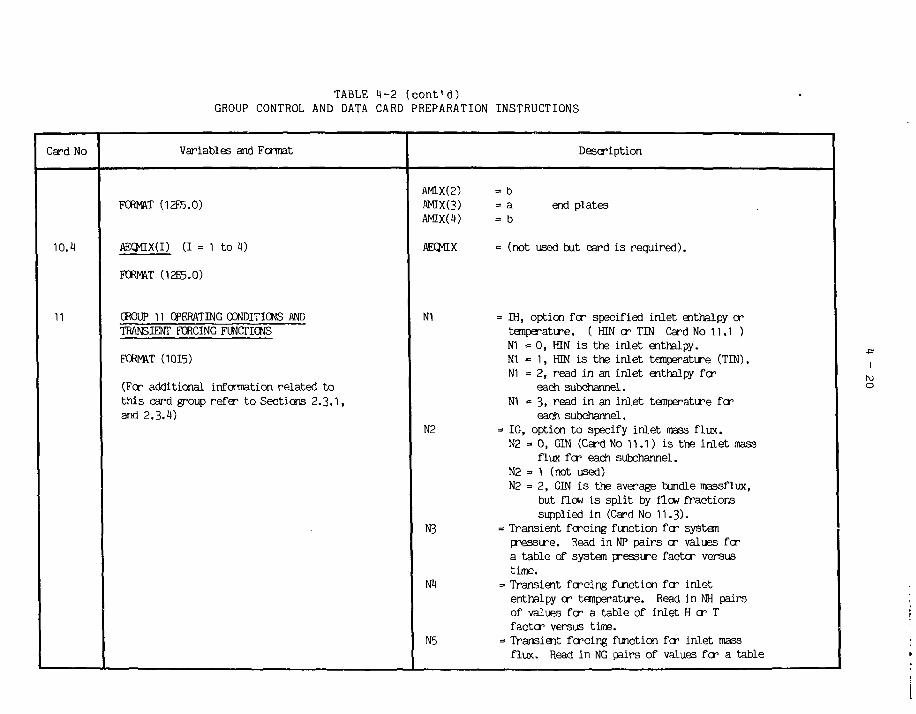
TABLE il-2 (cont'd)GROUP CONTROL AND DATA CARD PREPARATION INSTRUCTIONS
Card No
10.1
11
Variables and Format
FORMAT (12E5.0)
AECMLX(I) (I = 1 t o 4)
FORMAT (12E5.0)
CKOUP 11 OPERATING CONDITIONS ANDTRANSIENT FORCING FUNCTIONS
FORMAT (1015)
(Fer addi t iona l information r e l a t e d t othis card group refer to Sections 2.3.1,and 2.3.4)
Description
AMIX(2) = bAMIX(3) = a end platesAMIXCO = b
AECJ1IX = (not used but card is required).
N1 = IH, option for specified inlet enthalpy ortemperatire. ( HIN er TIN Card No 11.1 )NI = 0, HIN is the inlet enthalpy.N1 - 1, HIN is the inlet temperature (TIN).NI = 2, read in an inlet enthalpy for
each subchannel.N1 = 3, read in an inlet temperatire fer
each subchannel.N2 = IG, option to specify inlet mass flux.
N2 = 0, GIN (Card No 11.1) is the inlet massflux for each subchannel.
N2 = 1 (not used)N2 = 2, GIN is the average bundle massflux,
but flew is split by flow fractionssupplied in (Card No 11.3).
N3 = Transient forcing function for systempressure. Read in NP pairs or values fora table of system pressure factor versustime.
N4 = Transient forcing function for inletenthalpy cr temperatire. Read in NH pairsof values for a table of inlet H or Tfactor versus time.
N5 = Transient forcing function for inlet massflux. Read in NG pairs of values fer a table
I
o

TABLE H-2 (cont'd)GROUP CONTROL AND DATA CARD PREPARATION INSTRUCTIONS
Card No
11.1
11.2
11.3
11.1»
Var iab les and Format
PEXIT,HIN,GIN,AFLUX
FŒMftT (4F10.O)
HTNLETd) (I = 1 t o NfflANL)
FORMAT (6F10.0)
FDJLET(I) (I = 1 t o NCHANL)
FORMAT (12E5.0)
•
YP(I),FP(I) (i = i toN3)
FORMAT (125.0)
Description
of mass flux factor versus time.N6 = Transient fcrcing function fcr average
heat flux. Read in NQ pairs of values fcra table of heat flux factor vesus time.
Operating conditions, where:
PEXIT = The system pressure, (psia).HEN/TIN = Inlet enthalpy (Btu/lb) cr tanperatire (°F)
depending on N1.GIN = The inlet mass flux (Mlb/hr-ft2) to be
distributed by the N2 option.AFLUX = The average heat flux (MBtu/lr-ft2).
Optional Input - N1 = 2 or 3
Inlet enthalpy or temperature, where:
HINLET = The inlet enthalpy (N1 = 2) cr inlettemperatire (N1 =3) of each individualsubchannel; read one value fcr each sub-channel.
Optional Input - N2 = 2
Inlet flow rate, where:
FINLET = The individual subchannel inlet flow(F(I)/FTOTAL) fcr each subchannel.
Optional Input - N3 > 1
Pressure transient table, where:

TABLE H-2 (cont'd)GROUP CONTROL AND DATA CARD PREPARATION INSTRUCTIONS
Card No
11.5
11.6
11.7
12
Variables and Format
YH(I),FH(I) (I = 1 to M)
FORMAT (12E5.0)
YG(I),FG(I) (I = 1 toN5)
FORMAT (12E5.0)
YQ(I),FQ(I) (I = 1 toN6)
FORMAT (12E5.0)
CROUP 12 OUTPUT OPTION SELECT DATA
FORMAT (1015)
Description
YP = Transient time (sec) when factor i s applied.FP = Fraction of s teady-s ta te system pressure at
t rans ien t time (YP).
Optional Input - NM > 1
Enthalpy or temperature t r ans ien t t ab l e .
YH = The t rans ient time (sec) when factor i s applied.FH = The fraction of in le t enthalpy (Nl = 0 or 2)
or the fract ion of in le t temperature(N1 = 1 or 3) a t the t rans ien t time (YH).
Optional Input - N5 > 1
In le t flow cr p ress i re drop boundary condition t rans ien t t ab l e .
YG = The t rans ient time (sec) when factor i s applied.FG = The fraction of s teady-s ta te in le t flow a t the
transient time (YG).
Optional Input - N6 > 1
Heat flux transient table.
YQ = The transient time (sec) when factor is applied.FQ = The fraction of steady state heat flux at the
transient time (YQ).
N1 = NOUT, output print option.N1 = 0, print subchannel data only.N1 = 1, print subchannel data and crossflows only.N1 = 2, print subchannel data and fuel rod

TABLE 4-2 (cont'd)GROUP CONTROL AND DATA CARD PREPARATION INSTRUCTIONS
Card No Variables and Format Description
N2
N3
12.1 PRINTC(I) (1 = 1 to NI)
FORMAT (2413)
temperatures only.NI = 3> print subchannel data, crossflcws and fuel
rod temperatures.NPCHAN, an option fcr subchannel data printout.N2 = 0, print al l subchannel data.N2 > 0, read N2 subchannel identification
nunbers of subchannels to be printed.NPROD, an option fcr fuel rod heat fluxand/or temperature printout.N3 = 0, data for all rods are printed if
called f ar by N1.N3 > 0, read in N3 rod identification
numbers of rods to be printed.If NCHF (Card No 8) i s > 0, CHF data i s alsoprinted along with the rod data.
• NPNODE, an option fcr interior fuel nodetemperature printout fcr a l l rodsspecified by N3. Option only applies ifinterior rod temperatures are calculatedusing the fuel model (GROUP 8).N4 = 0, print rod centerline, rod surface
cladding surface température.N4 = 3 to 7, NI equally spaced interior
rod temperatures are printed along withthe cladding sirface temperatire,
« NPGAP, an option fcr GAP crossflcwprintout if called fcr by NI.N5 = 0, print crossflcw fcr all GAPS.N5 > 0, read GAP nunbers of GAPS to be printed.
Optional Input - N2 > 0
PRINTC = Read subchannel i d e n t i f i c a t i o n numbers of N2subchannels fo r which da t a i s t o be p r i n t e d .
N5
I
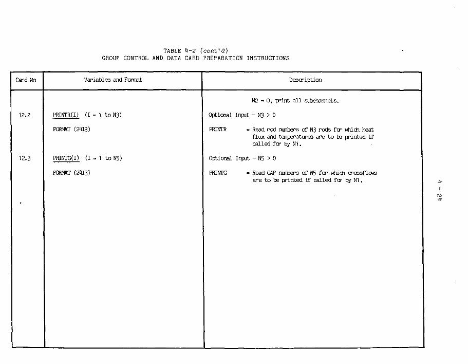
TABLE I-2 (cont'd)GROUP CONTROL AND DATA CARD PREPARATION INSTRUCTIONS
Card No Variables and Format Description
12.2 PRINTR(I) (I = 1 to N3)
FORMAT (2113)
12.3 PfflNTG(I) (I = 1 toN5)
FORMAT (2113)
N2 = 0, print a l l subchannels.
Optional Input - N3 > 0
PRINTR = Read rod nunbers of N3 r o d s fcr which hea t
flux and températures are to be printed ifcalled fcr by N1.
Optional Input - N5 > 0
PRINTG = Read GAP nunbers of N5 f c r which crossf lcwsare to be printed if called fcr by N1. 4r
I

4 - 2 5
4.2 CRNL Program Environment and User Interface
The relationship between the user and the CRNL ASSERT-4 programenvironment is illustrated in Figure 4.2. It is conveniently divided into twoparts; the user interface and the program file set.
User
ASSERT-4Program Environment
UserInterface
ProgramFile Set
Figure 4.2CRNL Program Environment
The program file set is a collection of permanent files which areaccessed via the user interface. These files contain user bulletins, ASSERT-4program source and test problem input data decks. The user interface providesaccess to the latest news about ASSERT, permits the user to run standard testproblems, to solve user-defined problems and to modify selected ASSERTroutines as required.
User Interface and ASSERT-4 Control Statement
The user interface consists of an ASSERT-4 control statement having thefollowing syntax:
ASSERT4,function,p1=v1 , Prf Vwhere : function = one of five valid ASSERT4 functions - LSTBULL,
GETPROB, RUNPROG, LSTPROG and MODPROGp. = control statement parameter iv. = value to be assigned to parameter i
When the LSTBULL function is called the ASSERT-4 user bulletin(s) arecopied to the user output file. This function recognizes two parameters:
0 = file to which user bulletins are to becopied (Default: OUTPUT)
V = ASSERT-4 version identifier (Default: V1R3)

- 26
When the GETPROB function is called the requested sample problem inputdata deck is retrieved from a library of sample problems, Table 1-3. Thisfunction recognizes three parameters:
TP = sample problem identifier (Default: 37RODBUN)0 = file to which test problem data are written
(Default: OUTPUT)V = ASSERT-4 version identifier (Default: V1R3)
Table 4-3ASSERT-1) Sample Problems
Identifier
37RODBUN
37CHANNEL
Description
37-element 1/2 bundle 1 metre sample problem data deck
37-element 1/2 bundle 6 metre U-1 type sample problemdata deck
When the RUNPROG function is called either the CRNL version or a usermodified version of ASSERT-4 is executed. This function recognizes fiveparameters:
I = ASSERT-4 input data file (Default: INPUT)0 = user output file (Default: OUTPUT)PL = user output file print limit in lines (Default: 20000)X = file containing a user modified version of
ASSERT-4 (Default: ASSRT4X)V = ASSERT-4 version identifier (Default: V1R3)
When the LSTPROG function is called a listing of specific ASSERT-4subprograms is generated. This function recognizes four parameters:
0 = file to which printable output is to be written(Default: OUTPUT)
SP = name(s) of subprograms to be listed (Default: ASSERTS)R = FTN reference map control parameter[10] (Default: 0)V = ASSERT-4 version identifier (Default: V1R3)

- 27
The MODPROG function allows the user to produce a modified version ofASSERT-iJ which can be executed by a subsequent call to the RUNPROG function.This procedure recognizes seven parameters:
I = user input file which contains user modificationsin CDC UPDATE utility format[11] (Default: INPUT)
0 = file to which printable output is to be written(Default: OUTPUT)
PL = output file print limit in lines (Default: 20000)R = FTN reference map control parameter[10] (Default: 0)OPT= FTN optimization level specification[10] (Default: 2)X = file to which modified version of ASSERT-4 is to be
written (Default: ASSRT4X)V = ASSERT-4 version identifier (Default: V1R3)
Using the User Interface Functions
To perform any one of the user interface functions, the user must includecontrol statements similar to the following in his job deck:
LIBRARY,APPLICS.ASSERTS,LSTBULL,0=BULL.
Executing the LIBRARY control statement makes the ASSERTS controlstatement available. In this case, when the ASSERT4 control statement isprocessed, the current ASSERT-4 user bulletins are copied to the local fileBULL. Other user functions require additional input data supplied by theuser. In particular, the RUNPROG function requires a input data deckconsisting of information described in the Section 4.1.

5 - 1
5. Sample Problem
In this section, a sample problem and solution are presented toillustrate how ASSERT-4 can be used to model flow and heat transfer in rodbundles.
Solving the sample problem requires that steady—state flow and voiddistributions be computed for a 6-metre channel containing 12 37~rod bundles,Figure 5-1, and that minimum critical heat flux ratios, MCHFR's, be computedfor this channel. This sample problem is similar to 37CHANNEL, the 37-rodbundle sample problem listed in Table 4-3.
Figure 5.1Channel Geometry-
Inlet
1 -
1 2 3 4
Flow
5 6 7 8 9 10 11 12 Outlet
Channel Data
Length (overall) 234.0Diameter (i.d.) 4.01No of Bundles 12
inin
Bundle Data
Length (overall) 19.5No of Elements 37
Fuel Element Data
No of Diameter Pitch PowerRing Elements (in) Radius Offset Factor
(in) (deg)
CentreInnerIntermediateOuter
161218
0.5150.5150.5150.515
0.0000.5901 .1321.705
0.0 0.82830.0 0.85715.0 0.93210.0 1.103
in
To solve this problem using the version of ASSERT available on the ChalkRiver computers, a job deck identical to the one listed in Figure 5.2 must beprepared.

5 - 2
Figure 5.2Sample Job Deck
ASSTPRB,BXXXX-YYYYY,T250,I045,CM320000.LIBRARY,APPLICS.ASSERT4.RUNPR0G.7/8/9 END OF RECORD
/ ASSERT-4 37-ELEMENT HALF BUNDLE 6-METRE PROBLEM/ (CONCENTRIC GEOMETRY, COSINE HEAT FLUX PROFILE, AND GRID SPACERS)
/> MAXT1500
/> CASE/TITLE CARD3160 37-ROD HALF BUNDLE
/> CARD GROUP 1 : WATER/STEAM1 3 f\I j U
.100 35.1.00 102.150.358.4250.401 .0350.431.7440.454.0520.471 .1600.486.2680.499.9840.523.9920.534.6
1000.544.61080.554.01160.562.91280.575.41360.583.31440.590.81520.598.01600.604.91680.611 .51760.617.91840.624.11920.630.02000.635.82080.641 .42160.646.82240.652.12320.657.22400.662..12480.666.9
0.016020.016140.018090.018650.019120.019500.019820.020130.020430.021010.021300.021590.021880.022170.022620.022920.023230.023540.023870.024200.024540.024900.025260.025650.026050.026470.026920.027390.027900.02845
2947.0331.103.1 .1 .1 .0 .0 .0.0 .0 .0 .0.0.0 .0 .0 .0.0.0 .0 .0 .0 .0 .0 .0 .0 .0 .0 .0 .
01390843203255005540891377697567581539884890144596409023769533603312562915627263255452397822538212101997818831177581675215806149161407613266
U-1 : ASSERT-4PROPERTY TABLE
3.02069.330376409434454471487516
96.6.1.8.8.2.7.7.7
530.0542554566532593604614624634643653662672681690700709719729
.4
.6
.2
.9
.6
.0
.2
.2
.0
.7• 3.7.1.5.8.1.5.0.1
/> CARD GROUP 2 : FRICTION FACTOR AND2 1
.186- .2000.02.0 1.5
0 0 c 0 0 1
1077.1106.1194.1201.1204.1204.1204.1203.1202.1198.1195.1192.1189.1186.1181.1177.1173.1169.1164.1159.1154.1149.1144.1138.1132.1125.1118.1111.1103.1095.
1.11108573279962330589723166475
TWO-PHASE1 1
nm1 .0 .0 .0 .0 .0 .0 .0 .0 .0 .0 .0 .0 .0 .0 .0 .0 .0 .0 .0 .0 .0 .0 .0 .0 .0 .0 .0 .0 .
00060036932630128327326425524223723222722321721 4211208206203200198195192189186182179175172
FLOW OPTIONS
0,0.0.0.0 .0 .0 .0 .0.0.0 .0 .0.0.0 .0 .0 .0 .0 .0 .0 .0 .0 .0 .0 .0 .0 .0 .0 .0 .
,3300,3600,3893,38063718
,3658360435503494337733253275322431743086303629842930287528202770271026602603255024902430237023102240
000000000000000000000000000,0,0,0,
.00517
.00478
.00288
.00252
.00168
.00205
.00190
.00176
.00164
.00142
.00132
.00123
.00115
.00107
.00096
.00089
.00083
.00076
.00071
.00065
.00060
.00055
.00050
.00046
.00041
.00037
.00033
.00030
.00026,00023

5 - 3
Figure 5.2 (cont'd)Sample Job Deck
/> CARD GROUP 33 25
0.00 0.00 .012 .180.250 .610 .292 .770.500 1.43 .542 1.750 1.51 .792 11
/>
542.792
00 .340CARD GROUP 4
.51
.44
AXIAL HEAT FLUX PROFILE TABLE
.083 .^40 .125 .340 .167 .410 .208 .510
.333 .910 .375 1.05 .420 1.19 .458 1.31
.583 1.59 .625 1.62 .667 1.63 .708 1.57•833 1.33 .875 1.09 .917 .900 .958 .590
SUBCHANNEL LAYOUT AND DIMENSION DATA34 34
0551.8045.449411031.609.8988
609.8988609.8988609.8988609.8988609.8988609.8988609.8988
1103111031110311103111031
8.110319.11031
10.0551.8045.449411.0684.8090.809012.0586.8090.809013.0750.8090.809014.0586.8090.809015.13681.6181.61816.0586.8090.809017.0750.8090.809018.0586.8090.809019.13681.6181.61820.0586.8090.809021 .0750.8090.809022.0586.8090.809023.0684.8090.809024.0675.8090.809025.0445.8090.809026.13501.6181.61827.0445.8090.809028.13501.6181.61829.0445.8090.809030.0675.8090.809031 .0223.4045.404532.0445.8090.809033.0445.8090.809034.0223.4045.4045
/> CARD GROUP 7 :7 2 0 24
.001 1 .042 2
.250 1 .292 2
.500 1 .542 2
2 .0733 .0734 .0735 .0736 .0737 .0738 .0739 .073
10 .073-11 .077
12 .07113 .16314 .16315 .07116 .07117 .16318 .16319 .07120 .07121 .16322 .16323 .071
-24 .07125 .07126 .07127 .07128 .07129 .07130 .071
-31 .07132 .07133 .07134 .071
80.60.40.20.
0.
.682
.682
.682
.682
.682
.682 340.
.682 320.
.682 300.
.682 280.
.578 180.
.499 90.
.285 145.
.285 95.
.499 150.
.499 150.
.285 205.
.285 155.
.499 210.
.499 210.
.285 265.
.285 215.
.499 270.
.586 0.
.462 90.
.462 30.
.462 30.
.462 330.
.462 330.
.462 270.
.462 180.
.338 120.
.338 180.
.338 240.
-23 .07722 .07720 .07719 .07718 .07716 .07715 .07714 .07712 .077
.578 0.
.492 340.
.492 320.
.578 300.
.492 280.
.492 260.
.578 240.
.492 220.
.492 200.
-30 .071 .586 180.
29 .071 .406 210.
28 .071 .586 240.
27 .071 .406 270.
26 .071 .586 300.
25 .071 .406 330.
-34 .071 .462 0.
33 .071 .462 300.
32 .071 .462 240.
GRID SPACER LOSS COEFFICIENT DATA2
.084 1 .125 2 .167 1 .209 2
.334 1 .375 2 .417 1 .459 2
.584 1 .625 2 .668 1 .709 2

5 - 4
Figure 5.2 (cont'd)Sample Job Deck
.750 1 .792 ' 2 .834 1 .875 2 .918 1 .959 21 .0822 .0823 .0824 .0825 .0826 .0827 .0828 .0829 .08210 .08211 .08212 .08213 .08214 .08215 .08216 .03217 .08218 .08219 .08220 .08221 .08222 .08223 .08224 .08225 .08226 .08227 .08228 .08229 .08230 .08231 .08232 .08233 .08234 .0821 .0612 .0563 .0504 .0435 .0376 .0337 .0308 .0329 .02810 .06211 .10012 .34013 .370

5 - 5
Figure 5.2 (cont'd)Sample Job Deck
141516171819202122
232425262728293031323334
.340
.100
.340
.370
.340
.100
.340
.370
.340
.100
.100
.560
.100
.560
.100
.560
.100
.460
.460
.460
.460/> CARD GROUP 8
812345678910111213141516171819
19.5151.515.5151.5151.515.515.515.515.515.5151.515'.515.5151.5151.515.515.515.5151.5151
19.103.932.103.103.932.857.828.857.932.103.103.932.103.103.932.857.932.103.103
/> CARD GROUP 9Q7
10234.
1024
.0290.
01
2123
212431261745176713281389:
.021.0
FUEL0
.2778
.1796
.2778
.2778
.1796
.2500
.0833
.2500
.1796
.2778
.2778
.1796
.2778
.2778
.1796
.2500
.1796
.2778
.2778
ROD222234
2025322718561678142912910
LAYOUT
.2778
.1528
.2778
.2778
.1528
.1667
.1667
.1667
.1528
.2778
.2778
.1528
.2778
.2778
.1528
.1667
.1528
.2778
.2778
AND
22.23.20.20.19.26.33.28.19.18.16.15.16.14.15.30.11 .12.12.
PROPERTY DATA
1954250915191954250925001667250025091954151925091954195425092500250915191954
23.24.21 .19.26.33.34.32.26.19.17.28.15.15.28.31.30.13.11.
2491250014072491250016670833166725002491140725002491249125001667250014072491
25.22.
25.34.
33.27.
18.27.
29.32.29.14.
CALCULATIONAL VARIABLES AND AXIAL NODING
.02
16671519
16671667
16671667
15191667
1667166716671519
DAT;

5-6
Figure 5.2 (cont'd)Sample Job Deck
/> CARD GROUP 10 : MIXING OPTIONS AND DATA10 0 0 0 0 0 0 10.0..050.
/> CARD GROUP 11 : OPERATING AND BOUNDARY CONDITION DATA11 • 1
1433-0 554 .2 3.4820 .2540/> CARD GROUP 12 : OUTPUT OPTION SELECT DATA
12I 1 0
1
19/> BLANK GROUP CONTROL CARD - END OF PROBLEM DEFINITION
0/> BLANK CASE/TITLE CARD - END OF RUN
07/8/9 END OF RECORD6/7/8/9 END OF FILE
This job deck consists of two records separated by a /EOR (end-of-record)statement. The first section contains the control cards which make theASSERT4 control statement available and cause the RUNPROG function to execute(Section 4.2). The second, all of the input which follows the first /EORstatement, contains the subchannel problem definition prepared according tothe user input data descriptions detailed in Section 4.1, Table 4-2. In thiscase, the user input includes the following groups of data:
- water/steam property data (Group 1)
- friction factor and two-phase flow options (Group 2)
- axial heat flux profile table (Group 3)
- subchannel layout and dimension data (Group 4)
- grid spacer data (Group 7)
- fuel rod layout and property data (Group 8)
- calculation control and axial noding data (Group 9)
- mixing options and data (Group 10)
- operating conditions (Group 11)
- output option select data (Group 12)
Figure 5.3 details the subchannel and fuel numbering used to prepare thesample problem input data. Each subchannel and each fuel rod is assigned aunique identification number used to assign input data and to identify problemsolution data to be included in ASSERT output.
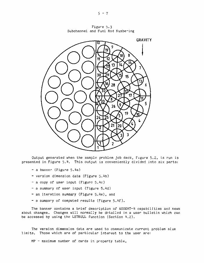
5 - 7
Figure 5.3Subchannel and Fuel Rod Numbering
GRAVITY
Output generated when the sample problem job deck, Figure 5.2, is run ispresented in Figure 5.4. This output is conveniently divided into six parts:
- a banner (Figure 5.4a)
- version dimension data (Figure 5.4b)
- a copy of user input (Figure 5.4c)
- a summary of user input (Figure 5.4d)
- an iteration summary (Figure 5.4e), and
- a summary of computed results (Figure 5.4f).
The banner contains a brief description of ASSERT-4 capabilities and newsabout changes. Changes will normally be detailed in a user bulletin which canbe accessed by using the LSTBULL function (Section 4.2).
The version dimension data are used to communicate current problem sizelimits. Those which are of particular interest to the user are:
MP - maximum number of cards in property table,

5 -
MC - maximum number of subchannels,MG - maximum number of subchannel gap connections,ML - maximum number of axial locations for gap and area variation,MX - maximum number of axial nodes plus one,MN - number of fuel collocation points plus three,MT - maximum number of fuel types,MR - maximum number of fuel rods,MZ - maximum number of axial locations for grid spacers,MK - maximum number of grid spacer types,MA - maximum number of subchannels that can have area variations,MS - maximum number of gaps that can have gap spacing variations,MW - maximum number of wall connections,MY - maximum number of axial fuel type divisions,
If user input defines a problem which violates these limits, ASSERT willnormally fail with an error mode[10].
A copy of user input follows the dimension data. This output is providedso that users can easily qheck to ensure that their input corresponds to theformats specified in Table 4-2. In future versions input data error checkingwill indicate the card or range of cards in error. Cards in error will beidentified by the card number assigned in this output.
The user input summary includes a table which contains a list of groupcontrol card parameter values followed by an interpreted summary of inputused to specify the current problem.
The iteration summary contains the outer iteration loop count (column 1),the maximum number of inner, or energy, iterations required to solve themixture and phasic energy equations (column 2), the maximum error in theenthalpy estimate and the associated axial location (subchannel, axial node)(column 3)i the maximum energy imbalance and the location (column 4), and themaximum relative flow error and location (column 5). Note that during thefirst two iterations, the inner iteration terminates on the user specifiedmaximum iteration limit. Experience has shown that there is no majoradvantage to increasing this limit much beyond 10. Similarly, if a steady-state calculation is going to converge it will do so within 30 outeriterations and normally within 10 iterations.
The summary of computed results contains:
- channel overall mass and energy balances (page 5~23)
- subchannel exit condition summary (page 5-23)
- bundle average results as a function of axialposition (page 5-24)
- individual subchannel results as a functionof axial position (page 5-25)
- fuel rod heat fluxes and temperatures as a function ofaxial position (page 5-27), and
- CHF calculation results (page 5-28)

5 - 9
The amount of data output in this summary depends primarily on optionsselected through Group 12 data (Table 4-2). A summary of selected gapcrossflows as a function of axial position was omitted by choice.
In reporting the sample problem solution, we chose to output detailedsubchannel results for subchannels 1 and 10. Since the channel is horizontaland subchannel 10 is above 1 (Figure 5.3), one would expect the void to behigher in 10. By referring to pages 5-25 and 5-26 , we see that this is whatis predicted by ASSERT-4. This illustrates a fundamental difference betweenASSERT-4 advanced drift-flux model and COBRA-IV results for this problem.COBRA-IV is not designed to account for lateral phase separation. Thus, theCOBRA-IV solution to this sample problem predicts that subchannels 1 and 10have the same void.
Solution of this sample problem required that a CHF calculation beperformed. To generate the reported CHF analysis we chose to use the W~3 CHFcorrelation. The results (page5~28) show that CHF (MCHFR=1.0) occurs between175.5 and 185.25 inches from the channel inlet in subchannel 9 on the surfaceof fuel rod 19 (Figure 5.3).
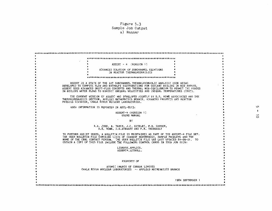
ASSERT IS A STATE OF THE ART SUBCHANNEL THERMALHÏDRAULIC ANALYSIS CODE BEINGDEVELOPED TO COMPUTE FLOW AND ENTHALPY DISTRIBUTIONS FOR COOLANT BOILING IN ROD ARRAYS.ASSERT USES ADVANCED DRIFT-FLUX CONCEPTS AND THERMAL NON-EQUILIBRIUM TO PERMIT THE PHASESIN BOILING WATER FLOWS TO EXHIBIT UNEQUAL VELOCITIES AND UNEQUAL TEMPERATURES (UVUT).
THE CURRENT VERSION OF ASSERT WAS DEVELOPED JOINTLY BY D.S. ROWE ASSOCIATES AND THETHERMALHYDRAUICS SECTION, APPLIED MATHEMATICS BRANCH, ADVANCED PROJECTS AND REACTORPHYSICS DIVISION, CHALK RIVER NUCLEAR LABORATORIES.
USER INFORMATION IS REPORTED IN AECL-8573:
ASSERT-ll (VERSION 1 )USERS MANUAL
BY
R.A. JUDD, A. TAHIR, J . C . KITELEY, M.B. CARVER,D.S. ROWE, D.G.STEWART AND P.R. THIBEAULT
TO FURTHER ASSIST USERS, A BULLETIN FILE IS MAINTAINED AS PART OF THE ASSERT-1J FILE SET.THE USER BULLETIN FILE CONTAINS LISTS OF CURRENT REFERENCES, SAMPLE PROBLEMS AND THENAME OF THE CRNL CONTACT PERSON. THE USER BULLETIN FILE WAS LAST UPDATED 8 1 - 0 9 - 0 1 . TOOBTAIN A COPY OF THIS FILE INCLUDE THE FOLLOWING CONTROL CARDS IN YOUR JOB DECK:
LIBRARY,APPLICS.ASSERTt.LSTBULL.
PROPERTY OF
ATOMIC ENERGY OF CANADA LIMITEDCHALK RIVER NUCLEAR LABORATORIES — APPLIED MATHEMATICS BRANCH
198« SEPTEMBER 1

Figure 5.3Sample Job Outputb) Dimension Data
ASSERT-1 DIMENSION PARAMETERS
M OMH-MÏ -MA-M0-
3»1117
MG-MP-MK-ML-N I -
5130
it18
MR-MX-MZ>MT-N1-
192530
16
HN-ME-MS-M I -M 1 -
625
1it
1014
I

Figure 5.3Sample Job Output
c) Copy of User Input
CARDNUMBER
00001000020000300001000050000600007000080000900010000110001200013
0003800039000100001100012000130001100015000160001700018000190005000051000520005300051000550005600057
0008600087000880008900090000910009200093000910009500096
1
////
10 20
COPÏ OF
30
USER INPUT TO ASSERT4
CARD IMAGE40
ASSERT-1 37-ELEMENT HALF(CONCENTRIC GEOMETRY, COSINE HEAT
/> MA XV5000
/> CASE/TITLE CARD3160 1 37-ROD HALF BUNDLE
/> CARD GROUP 1 :1
.1001.00
3035.
1 0 2 .150.358.1
232o!ô57.22100.662.12180.666.9
00.016020.0161 40.01809
0.027390.027900.02845
/> CARD GROUP 2 :2
. 1 8 6 -0 . 02 . 0
1.200
1.5
0 0
/> CARD CROUP 3 :3
O.CO.250.500.7501.00
250.00.6101.131.51.310
.042 .180
.292 .770
.542 1.51
.792 1.44
/> CARD GROUP 1 :1123
323331
310551.1103111031
0115.0115.0223.
34 08045.4491.609.8988.609.8988
8090.80908090.80904045.4045
/> CARD GROUP 7 :7
.001
.250
.500
.75012
21111
.082
.082
0 24.042 2.292 2.542 2.792 2
rtATER/STEAM
2947.0331.10
3.01390
0.149160.140760.13266
U-1 :PROPERTY
3.02069.96330.6
709.5719.0729.1
FRICTION FACTOR AND0 0
AXIAL HEAT
.083 .240 .
.333 .910 .
.583 1.59 .
.833 1.33 .
0 i
50
BUNDLE 6-METREFLUX PROFILE,
ISSERT-4TABLE
1077.11106.11194.1
1111.41103.71095.5
TWO-PHASE1 1
FLUX PROFILE TABLE
125 .340375 1.05625 1.62875 1.09
SUBCHANNEL LAYOUT0 02 .073 .3 .073 .4 .073 .
33 .071 .34 .071 .
0 0682 80.682 60.682 40.
338 180.338 240.
.167 .410
.420 1.19
.667 1.63.917 .900
410
000
FLOW
208458708958
60. . . V
PROBLEMIND GRID
.000
.600
.369
.179
.175
.172OPTIONS
.5101.311.57.590
AND DIMENSION DATA
-23 .07722 .07720 .077
*
GRID SPACER LOSS COEFFICIENT2
.084 1 .
.334 1
.581 1
.831 1
125 2375 2625 2875 2
.167 1
.417 1
.668 1
.918 1
578.492.492
DATA
.209
.459
.709
.959
0 .340.320.
2222
000
000
70. . . V .
SPACERS)
.3300
.3600
.3893
.2370
.2310
.2240
0 .0 .0 .
0 .0 .0 .
80V.
005170047800288
0Ö03O0002600023
CARDNUMBER
00001000020000300004000050000600007000080000900010000110001200013
0003800039000400004100042000430004400045000460004700048000490005000051000520005300054000550005600057
0008600087000880008900090000910009200093000940009500096

Figure 5.3 (cont'd)Sample Job Output
c) Copy of User Input
00097
001260012700128001290013000131
0016000161001620016300161001650016600167
001*810018200183001810018500186001870018800189031900019100192001930019100195001960019700198001990020000201002020020300201
3 .082
32 .08233 .08231 .082
1 .0612 .0563 .050
32 .16033 .16031 .160
/> CARD CROUP 8.8 19 191 .5151.1032 .515 .9323 .5151.103
17 .515 .93218 .5151 .10319 .5151 .103
/> CARD GROUP 99
10 10 .02 .2 3 1 . 21 90. 1
/ > CARD GROUP 1010 0 00 .0 .
.0500 .
/> CARD GROUP 1111 1
1133.0 551/> CARD GROUP 12
12 2 21 10
19
: FUEL ROD LAYOUT AND PROPERTY DATA0 0 21.2778 2 .2778
21.1796 22 .15232.2778 3.2778
13.1796 12.15288.. 2778 9.27789.2778 10.2778
: CALCULATIONAL
02 .02. 0
22.1951 23.219123.2509 21.250020.1519 21.1107
11.2509 30.250012.1519 13.110712.1951 11.2191
25 .22 .
2 9 .1 1 .
VARIABLES AND AXIAL NODING
: MIXING OPTIONS AND DATA0 0 0 0
: OPERATING AND
.2 3.1820: OUTPUT OPTION1
/> BUNK GROUP CONTROL CARD - END0
/> BLANK CASE/TITLE CARD - END OF0
1
BOUNDARY CONDITION DATA
.2510SELECT DATA
OF PROBLEM DEFINITION
RUN
16671519
16671519
DATA
00097
001260012700128001290013000131
0016000161001620016300161001650016600167
00181001820018300181001850018600187
00189001900019100192001930019100195001960019700198001990020000201002020020300201
I
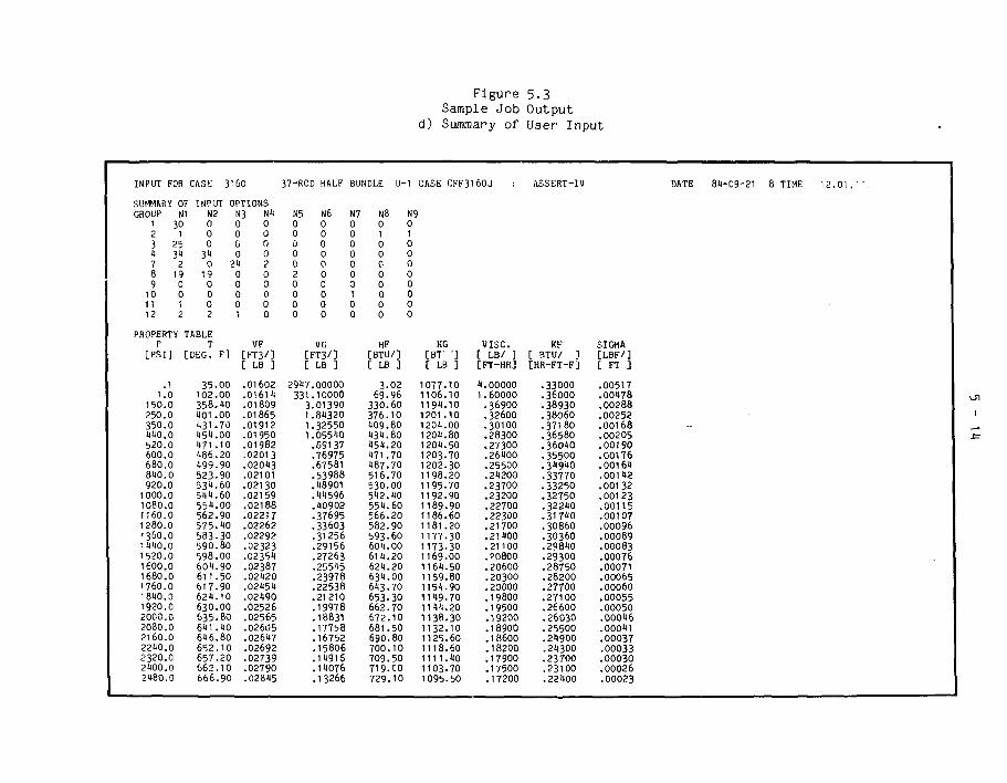
Figure 5.3Sample Job Output
d) Summary of User Input
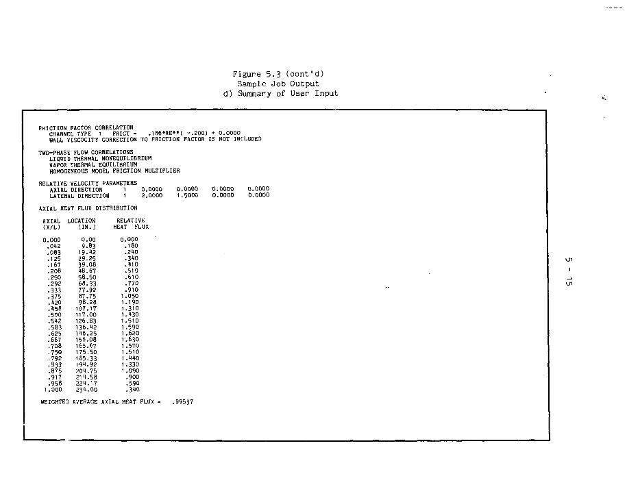
Figure 5.3 (cont'd)Sample Job Output
d) Summary of User Input

Figure 5.3 (cont'd)Sample Job Output
d) Summary of User Input

Figure 5.5 (cont'd)Sample Job Output
d) Summary of User Input
TOTAL FLOW AREA - 2.6517 [ S Q . I N . ]TOTAL HEATEDTOTAL WETTED
GRID SPACER DATA
AXIAL LOCATION(X/L)
.0010
.01120
.081)0
.1250
.1670
.2090
.2500
.2920
.3310
.3750
.1170
.1590
.5000
.5120
.5810
.6250
.6680
.7090
.7500
.7920
.8310
.8750
.9180
.9590
PERIMETER =. 29.9322 [ I N . ]PERIMETER - 36.3210 [ I N . ]
: 21 AXIAL SPACER LOCATIONS
SPACER TYPE(NO.)
121212121212121212121212
.018115 [SQ.FT. ]2.191350 [ F T . ]3.027000 [ F T . ]
I

Figure 5.3 (cont'd)Sample Job Output
d) Summary of User Input
SPACER TYPE
CHANNELNO.
159
131721252933
SPACER TYPE,
CHANNELNO,
159
131721252933
1
DHAG
.08?0
.0820
.0820
.0820
.0820
.0820
.0820
.0820
.0820
2
DRAGCOEFF.
.0610
.0370
.0280
.3700
.3700
.3700
.5600
.5600
.1600
CHANNELNO.
26
10111182226303«
CHANNELNO.
26
10I t1822263031
DRAGCÜEFF.
. 0 8 2 0
.0820
. 0 8 2 0
. 0 8 2 0
. 0 8 2 0.0820.0820.0820.0820
DRAGCOEFF.
.0560
.0330
.0620
.3100
.3^00
.3400
.1000
. 1 0 0 0
.1600
CHANNELNO.
37
111519232731
CHANNELNO.
37
111519232731
DRAGCOEFF.
.0820
.0820
.0820
.0820
.0820.0820.0020.0820
DRAGCOEFF.
.0500
.0300
.1000
.1000
.1000
.1000
.5600
.1)600
CHANNELNO.
I)8
1216202i)2832
CHANNELNO.
i|8
1216202D2832
DRAGCO^FF.
.0820
.0820
.0820
.0820
.0820
.0820
.0820
.0820
DRAGCOEFF.
.0130
.0320
.31100
.3400
.3«00
.1000
.1000
.1600
Ul
I
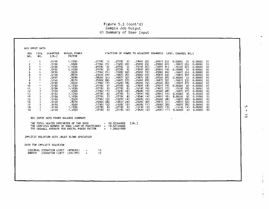
Figure 5.3 (cont'd)Sample Job Output
d) Summary of User Input
ROD INPUT DAT.«
ROD TYPENO
123456789
10111213141516171819
NO.
1111111111111111111
ROD INPUT
THE TOTAL
DIAMETER RADIAL POWER[ IN. ]
.5150
.5150
.5150
.5150
.5150
.5150
.5150
.5150
.5150
.5150.5150.5150.5150.5150.5150.5150.5150.5150.5150
FACTOR
1.1030.9320
1.10301.1030
.9320
.8570
.8280
.8570
.93201.10301.1030
.93201.10301.1030
.9320
.8570
.93201.10301.1030
DATA POWER BALANCE SUMMARY
HEATED PERIMETER OF THE RODSTHE COMPUTED NUMBER OFTHE OVERALL AVERAGE ROD
.27781
.17961
.27781
.27781
.17961
.25001
.08331
.25001
.17961
.27781
.27781
.17961
.27781
.27781
.17961
.25001
.17961
.27781
.27781
RODS (SUM OF FRACTIONS)RADIAL POWER FACTOR
IMPLICIT SOLUTION WITH INLET FLOWS SPECIFIED
DATA FOR IMPLICIT SOLUTION
EXTERNAL ITERATION LIMITENERGY ITERATION LIMIT
(NTRIES)( IELIMT)
1010
FRACTION OF f
1)21)
2)3)
21)24)3D26)17)4)5)
17)6)7)
13)28)13)8)9)
= 29= 18
1
.27781
.15281
.27781
.27781
.15281
.16671
.16671
.16671
.15281
.27781
.27781
.15281
.27781
.27781
.15281
.16671
.15281
.27781
.27781
>OWE
2)22)
3)4)
20)25)32)27)18)5)6)
16)7)8)
14)29)12)9)
10)
.93346805
.50120000
.00021889
H TO ADJACENT
.19541
.25091
.15191
.19541
.25091
.25001
.16671
.25001
.25091
.19541
.15191
.25091
.19541
.195«
.25091
.25001
.25091• 1519(.19511
[IN.]
22)23)20)20)19)26)33)28)19)18)16)15)16)14)15)30)11)12)12)
CHANNELS
.24911
.25001
.11071
.21911
.25001
.16671
.08331
.16671
.25001
.21911
.14071
.25001
.24911
.24911
.25001
.16671.25001. 1 407 (.24911
(ADJ
23)24)21)19)26)33)31)32)26)19)17)28)15)15)28)3D30)13)11)
0 .
0 .
0 .
#
0 .
o!0 .
o'.
CHANNEL NO.
00001166711519100001166711667100001166711667100001151911667100001000011667116671166711519100001
0)25)22)
0)25)
0)33)27)
0 )18)27)
0 )0)
29)32)29)11)
0)
j
0000000000000000000
.00001
.00001
.00001
.00001
.00001
.00001
.00001
.00001
.00001
.00001
.00001
.00001
.00001
.00001
.00001
.00001
.00001
.00001
.00001
0)0)0)0)0)0)0)0 )0)0)0 )0)0)0)0)0)0)0 )0)

Figure 5.3 (cont'd)Sample Job Output
d) Summary of User Input
CONVERGENCE CRITERIA :
ENTHALPY ERRORENERGY ERRORFLOW ERROR
TRANSIENT
TOTAL 1NUMBER
CALCULATION
SOLUTION
fRANSIENTOF TIME
(HEBROR)(EERROR) NOT(FERROR)
PARAMETERS :
TIMESTEPS
PARAMETERS
CHANNEL LENGTH (Z)NUMBER OF
(TTIME)(NDT)
_AXIAL NODES (NDX) =
AXIAL NODE LENGTHBUNDLE ORIENTATION
LATERAL K
(DX)(THETA)
FACTOR (KIJ)
AXIAL NODINC AND POWER
NODEJ
12315678910tl12
X(J-M)[IN.]
9.7519.5029.2539.0018.7558.5068.2578.0087.7597.50107.25117.00
=
FACTORS
USED
23«.
9.90.
1.
FOR
DX(J) FACTOR[IN
9.9.9.9-9.9.9.9.9.9.9.9.
.] QAX(J)
75757575757575757575 175 175 1
08932100290«37«716005601689«8100980611 «821533705
_
=
-
000021
75000000
0000
.0200 [BTU/LB]
.0200 [BTU/S-FT]
.0200 [DF/F]
0.0000 [SECONDS]0
[INCHES]
[INCHES][DEGREES]
21 NODES

Figure 5.3 (cont'd)Sample Job Output
d) Summary of User Input
13 126.751U 136.5015 116.2516 156.0017 165.7518 175.5019 185.2520 195.0021 201.7522 211.5023 221.2521 231.00
9.7b9.759.759.759.759.759.759.759.759.759.759.75
THERMAL MIXING PARAMETERSLIQUIDVAPOR
0 00 0
VOID DIFFUSION PARAMETERSALPHAALPHA EQUIL.
OPERATING CONDITIONS
0 01 0
SYSTEM PRESSURE (PEXIT)INLET TEMPERATURE (TIN)INLET ENTHALPY (HIN)AVG. MASS VELOCITY (GIN)AVG. HEAT FLUX (AFLUX)
THEORETICAL ENERGY ADDED
ENERGY ADDED * AFLUX *
1.16971.55001.60511.62501.60001.53981.17531.38501.2090.9958.7150.1610
0.00000.0000
.05000.0000
» 1133.0551.20551.863.1820.25100
(ASSUMING
PHTOT * Z /
UNIFORM INLET ENTHALPY/TEMPERATUREUNIFORM INLET MASS
CALCULATION OF H-H
VELOCITY
PRESSURE
0.00000.0000
0.00000.0000
[PSIA][DEGREES[BTU/LB][MILLION[MILLION
NORMALIZED
3600.
DROP IS NOT INCLUDED
0.0000 0.0.0000 0.
0.0000 0.0.0000 0.
F]
LB/(HR-FT2)]BTU/(HR-FT2)]
00000000
00000000
AXIAL AND RADIAL HEAT FLUX PROFILES)
.31318E+O1 [BTU/SEC]

Figure 5.3Sample Job Output
e) Iteration Summary
ITERATION SUMMARY
ITERATNUMBER
MAX ITERENERGY
MAX H ERROR(BTU/LB) [ I , J ]
MAX E ERROR(BTU/S-FT) [1 , J ]
MAX F ERROR(DF/F) [ I . J ]
11117
.1118 [21,25]
.0533 [20,25]
.019« [21,25]
.2660 [ 2,21]
.0919 [ 2.23]
.0331 C 2.21]
.1365 [28,12]
.0606 [ 2,12]
.0121 [ 2,13]

Figure 5.3Sample Job Output
f) Summary of Computed Results
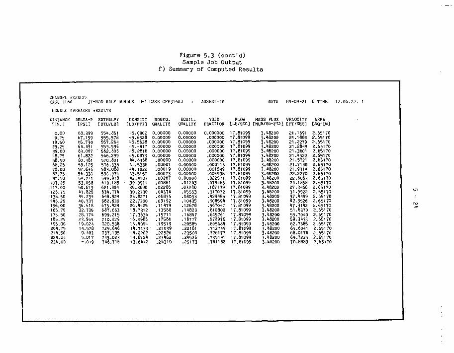
Figure 5.3 (cont'd)Sample Job Output
f) Summary of Computed Results
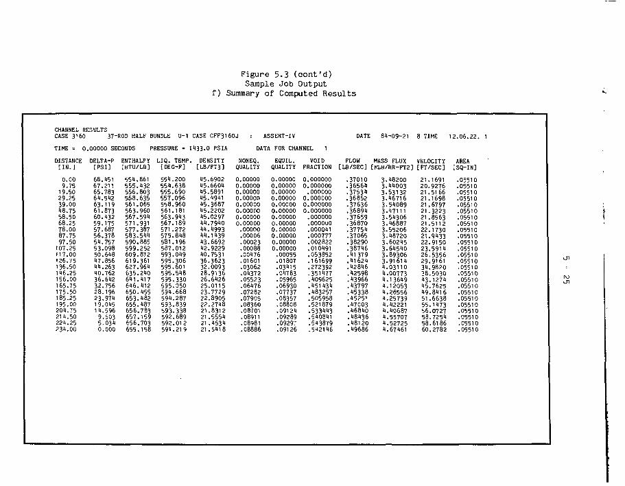
Figure 5.3 (cont'd)Sample Job Output
f) Summary of Computed Results

Figure 5.3 (cont'd)Sample Job Output
f) Summary of Computed Results

5 - 2 7
3
eu
4-> D. üC 4-> d)O 3 JJü O 3
— Q.•O E
m o O• -3 U
ind> M Os. a3 e >.00 to c
• ^ CO 10
t . e
co
<\J
MDO
12.
SCD
1
O
00
DA
TE
Va*wSSV
o
b .
ob l
U
1
S '33
b .
|
RO
D
iL
3
2
YLIi
CJ
a.X
- 3
(FU
E
QOce
ceO
«c
a
PU
RE
ceb la.
CO
ND
S
UJ
oo
8O
r , i
1 T
IMI
i d
X
cy
3 b.r3 •b, CC
HE
AM
BTU
b l
B^
1—1 t—V
OOOOOOOOOCM^OXCOM^ONOvChOM^OM^ONO
ooooo<uvocoo<w3 ivoir»«-(^fni- mvo roCT*t -=rao
QOOOOOCOdlT|Oin(MO>i-r- ^OCOOcoO l fl1 --<\J
ooooocosûin^-mmcoojaj^^--
^"" CO^D 00 t** D PO^T r^ COCO vO tf^ \T\ ( ^ U^ Û OO CNJ fM CO t ^ OJ O
o co rn o^ oo ^^ ^o t" ooeo o** ^ oj p C\J r\j ro ro ^ r*«- CT\ C1^ OI * I OO ^^ "T OO f ^ PO O v^1 ^ ^ CO OO ^™ 3" C^ i y GO F** OO GO OO 00 ÖO ^ î*
coinmocoir>moooinfno(Dinfnocoinmocoir\mo
• i i i i i i i i t i i i i i i i i i i i i t i
ocoiTiroocomrooooiAonoootnmocomroooomrn^ " ^ J 1 ^^ ^^ ^^ 00 CO 00 CO [• ^ M ^ i ^ ^ ^ ^^ï ^5 ^ï l^^ ^^\ ^ ^ y y ^^
^C\J f ia 1 u^vor^oo CT* o ^- eu n s IAVO t^oo ON O •— OJ
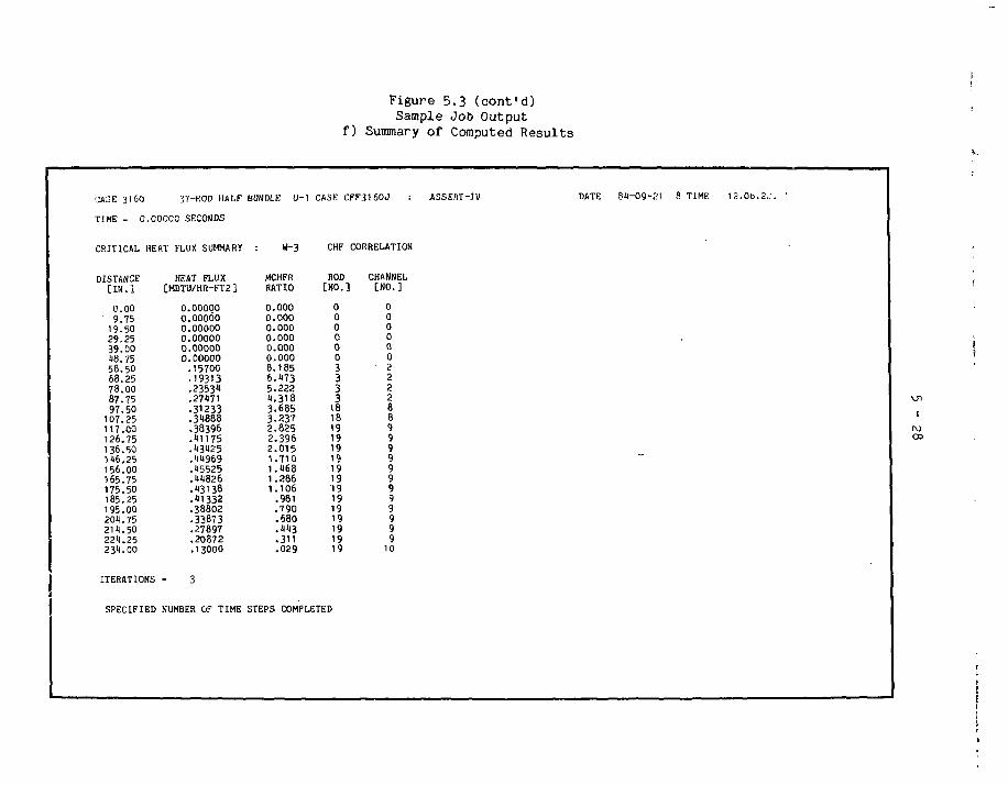
Figure 5.3 (cont'd)Sample Job Output
f) Summary of Computed Results
CASE 3160 37-ROD HALF
TIME - 0.00000 SECONDS
CRITICAL HEAT FLUX SUMMARY
DISTANCE[IN.]
0.009.75
19.5029.2539.00«8.7558.5068.2578.0087.7597.50
107.25117.00126.75136.50116.25156.00165.75175.50185.25195.00201. 75211.50221.25231.00
ITERATIONS
I
SPECIFIED
HEAT FLUX[MBTU/HR-FT2]
0.000000.000000.000000.000000.000000.00000
.15700
.19313
.2353«
.27471
.31233
.31888
.38396
.11175
.13125
.11969
.15525
.11826
.13138
.11332
.38802
.33873
.27897
.20872. 13000
3
NUMBER ÙF TIME
BUNDLE: U-1
: W-3
MCHFRRATIO
0.0000.0000.0000.0000.0000.0008.1856.1735.2221.3183.6853.2372.8252.3962.0151.7101.1681.2861.106
.981
.790
.680
.113
.311
.029
CASE
CHF
HOD[NO.
000000
3333
181819191919191919191919191919
STEPS COMPLETED
CFF3I6OJ : ASSERT-IV
CORRELATION
CHANNEL] [NO.]
000000222288999999999999
10
DATE 81-09-21 8 TIME 12.00.2..1. 1
UlI
oo

6 - 1
6. References
1. Carver,M.B., Tahir.A., Rowe.D.S., Tapucu.A. and Ahmad,S.Y., "ComputationalAnalysis of Two-Phase Flow in Horizontal Bundles", Nucl. Eng. & Design,v82, p12 (1983)
2. "ASSERT-4 Basic Theory Manual", Atomic Energy of Canada Limited, to bepublished.
3. Wheeler,C.L., Stewart,C.W., Cena.R.J., Rowe.D.S., Sutey.A.M., "COBRA-IV-I -An Iterim Version of COBRA for Thermalhydraulic Analysis of Rod BundleNuclear Fuel Elements and Cores", Battelle Pacific Northwest Laboratories,BNWL-1962 (1976 March)
JJ. Stewart,C.W., Wheeler,C.L., Cena.R.J., McMonagle.C.A., Cuta.J.M., andTrent,D.S., "COBRA-IV: The Model and Method", Battelle Pacific NorthwestLaboratories, BNWL-2214 (1977 July)
5. Ishii.M., Thermo-Fluid Dynamic Theory of Two-Phase Flow, Eyrolles, Paris(1975)
6. Selander,W.N., "Explicit Formulas for the Computation of Friction Factorsin Turbulent Pipe Flow", Atomic Energy of Canada Limited, AECL-635^, p6(1978 November)
7. Armand, A.A., "The Resistance During the Movement of a Two-Phase Systemin Horizontal Pipes", translated by V. Beak, AERE Trans.
8. Tong.L.S. and Weisman.J., Thermal Analysis of Pressurized Water Reactors,American Nuclear Society (1970)
9. Tahir.A., unpublished report (198*1 May)
10. "FORTRAN Extended (Version 1) Reference Manual", Control Data Corporation(1981 January 15)
11. "UPDATE Reference Manual", Control Data Corporation (1978 March 3D
12. Zuber,N. and Findlay.J.A., "Average Volumetric Concentration in Two-PhaseFlow Systems, J. Heat Transfer, v87 (1965)
13. Ohkawa.K. and Lahey.R.T.Jr., "The Analysis of CCFL Using Drift-fluxModels", Nuclear Engineering and Design, V61 (1980)
1*t. Lahey.R.T.Jr. and Moody,F.J., The Thermal-Hydraulics of a Boiling WaterNuclear Reactor, American Nuclear Society (1979)
15. Wallis.G.B., "The Thermal Speed of Single Drops or Bubbles in an InfiniteMedium", Int. J. Multiphase Flow, vol 1 (1975)

6 - 2
16. Lahey.R.T.Jr., Shiralkar,B.S., Radcliffe.D.W., and Polemik,E.E., "Out-of-Pile Subchannel Measurements in a Nine-Rod Bundle for Water at 1000 psia",Progress in Heat and Mass Transfer, Vol VI, Pergamon Press, New York(1972)
17. Tahir.A. and Kiteley,J.C., unpublished report (1981 June)
7 - 1
7. Acknowledgement
The authors wish to acknowledge, with thanks, the contributions ofS.Y. Ahmad who had the foresight to start the ASSERT subchannel developmentprogram, Doug Connelly and Alistair Middleton who prepared the cover page andsome of the drawings and S. Baker who used her new wordprocessor to print thetext.
The authors also acknowledge with thanks the financial support providedby Ontario Hydro and AECL CANDU Operations through the CANDEV program.
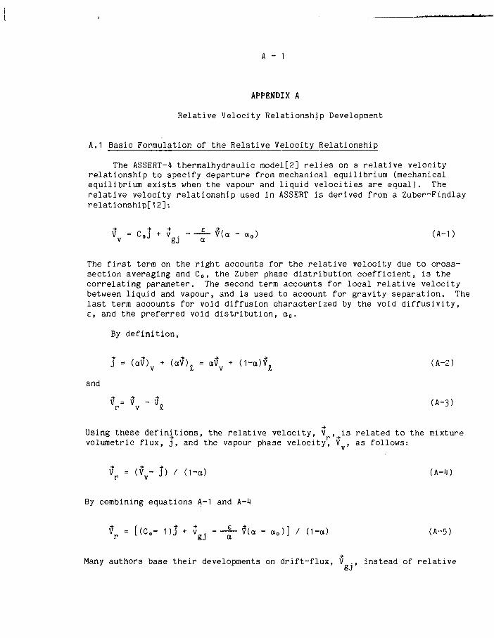
A - 1
APPENDIX A
Relative Velocity Relationship Development
A.1 Basic Formulation of the Relative Velocity Relationship
The ASSERT-4 thermalhydraulic model[2] relies on a relative velocityrelationship to specify departure from mechanical equilibrium (mechanicalequilibrium exists when the vapour and liquid velocities are equal). Therelative velocity relationship used in ASSERT is derived from a Zuber-Findlayrelationship!; 12]:
vVc°j + v V - ^ ( a - a o ) (A~1)
The first term on the right accounts for the relative velocity due to cross-section averaging and C o, the Zuber phase distribution coefficient, is thecorrelating parameter. The second term accounts for local relative velocitybetween liquid and vapour, and is used to account for gravity separation. Thelast term accounts for void diffusion characterized by the void diffusivity,e, and the preferred void distribution, oto.
By definition,
j = (aV) + (aV) = aV + (1-a)v\ (A-2)
and
V = V - V. (A-3)r v i,
Using these definitions, the relative velocity, V ,^is related to the mixturevolumetric flux, j , and the vapour phase velocity^ V , as follows:
V = (V - j) / (1-a) (A-iJ)r v
By combining equations A-1 and A-4
Vp = [(C„- 1)j + vgJ - -~ via - a0)] / (1-a) (A-5)
Many authors base their developments on drift-flux, V ., instead of relativeoJ
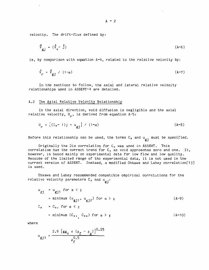
A - 2
velocity. The drift-flux defined by:
Vgj = (Vv- j) (A-6)
is, by comparison with equation A-lJ, related to the relative velocity by:
V = V / (1-a) (A-7)
In the sections to follow, the axial and lateral relative velocityrelationships used in ASSERT-4 are detailed.
A.2 The Axial Relative Velocity Relationship
In the axial direction, void diffusion is negligible and the axialrelative velocity, U , is derived from equation A-5:
Up = [(Co- D j + ugj] / (1-a) (A-8)
Before this relationship can be used, the terms Co and u . must be specified.
Originally the Dix correlation for Co was used in ASSERT. Thiscorrelation has the correct trend for Co as void approaches zero and one. It,however, is based mainly on experimental data for low flow and low quality.Because of the limited range of the experimental data, it is not used in thecurrent version of ASSERT. Instead, a modified Ohkawa and Lahey correlation[13]is used.
Ohkawa and Lahey recommended compatible empirical correlations for therelative velocity parameters Co and u .:
u . = u .. for a < xgj gj 1
= minimum (u , u _ ) for a > x (A-9)
Co = C , for a < x
= minimum (C01 C02) for a > x (A-10)»
where
2.9 [ggc o (pf - Pg)30'25
Ugj1 - p0.5

A - 3
ugj2
[ggc o <Pf - P f)]0'
pf
[1.2-0.2 & ° ' 5 ] [ 1 - [fpf
Co« = 1 + 0.2 [ 1 - (-*) ] [ 1 - (f-^pf
o = the surface tension
X = 0.588 - 1.817 * + 2.0 tpz - 3.313 if*3
« = (Pg/P f) ° ' 5
Y = max (Y , , 3 . 1 3 6 ) , and
Yi= 4 .72 - 17 .27 * + 56 * 2 + 113 * 3
- 1250.6 ill" + 3.0397 Hi5 - 2431 .8 i|<6
Using these correlations, when a approaches one equation A-8 becomes:
Ur = [(Co« - 1) J + ugj2] / (1-ct) (A-11)
For a = 1.0, C 0 2 = 1.0, u -2 = 0.0 and Up is indeterminant (0/0). To remove
this anomaly, Tahir recommended that both C 0 2 and u ._ be multiplied by afactor, F: gJ
F - [^ - (f^)2 f
Currently, the value of m used is 0.5. This allows U to approach zeroasymptotically when void fraction approaches one.
In ASSERT, the axial relative velocity, U , is expressed in terms ofmixture mass flux. This relationship is derived as follows. The mixturevolumetric flux, j, can be expressed as (see Lahey and Moody[1i)jequation 5.64):

A - H
G (pf "a (1--) (A-13)
Combining equation A-8 and A-13 yields:
i Ç + (pf -
J = P P~a [(Co - 1) J + u ]
G (pf ' P K )
- + a — • S- u .P P gJ
(Pf " pJ
Combining equations A-8 and A-l4 gives the required result:
- PJ
U(Co- 1) -r + a
(pf - p )a t • S (C o - 1)
**• + u .gj
/ (1-a)
(Co - D - + u
[ 1 - a f , 8 (Co - 1) ]
/ (1-a) (A-15)
Equation A-15 is the axial relative velocity relationship used in ASSERT.Equations A-9 and A-10 are used to compute u . and Co.
A.3 The Lateral Velocity Relationship
In the lateral direction, voids are assumed to be distributed uniformlyand by definition the Zuber phase distribution coefficient, Co, is 1.0. Also,in contrast to the axial direction, diffusion is significant because a highvoid gradient may exist between subchannels. Applying these assumptions tothe lateral component of equation A-5 gives the lateral relative velocityrelationship:
V(o - a0)] (A-16)
The local relative velocity, v ., is expressed in terms of terminalbubble rise velocity v : 8J
(A-17)
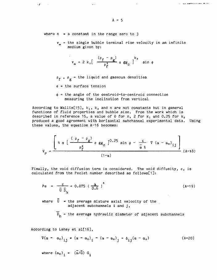
A - 5
where n = a constant in the range zero to 3
vm = the single bubble terminal rise velocity in an infinitemedium given by:
r (pf " pg} ika
vœ = 2 k,[ — B - o ggc ] sin «
pf , p = the liquid and gaseous densities
o = the surface tension
<f> = the angle of the centroid-to-centroid connectionmeasuring the inclination from vertical
According to Wallis[15], klf k2 and n are not constants but in generalfunctions of fluid properties and bubble size. From the work which isdescribed in reference 15, a value of 0 for n, 2 for k! and 0.25 for k2produced a good agreement with horizontal subchannel experimental data. Usingthese values, the equation A-16 becomes:
r f va iO 25 e
M»! °~ o gg J sin <(. - -— V (a - a0)
L pf a l Jv = ï (A-18)
Finally, the void diffusion term is considered. The void diffusity, e, iscalculated from the Peclet number described as follows[1]:
Pe = — 0.075 ( Tpr )" (A-19)0 6
where U = the average mixture axial velocity of theadjacent subchannels i and j,
D = the average hydraulic diameter of adjacent subchannels
According to Lahey et al[1ô],
V(a - a,,)^ = (a - a 0 ) A " (a - a0) = A£ (a - a0) (A-20)
where (a0). - (ä/G) G.

A - 6
a = average void in subchannels i and j, (a.+ a.)/2
G = average axial mass flux in subchannels i and j, (G + G )/2
Combining equations A-18 and A-20 gives:
sin d> - - £ - A. .(a - o0)ä 1J
O-a)
By comparison with equation A-7, it is observed that the numerator of equationA-21 is equivalent to the lateral drift-flux, V ..
oJ
From equation A-21 one observes that V goes to zero as a goes to zero;however, as a goes to one, V ., the numerator in equation A-21, remains finite
and V goes to infinity. This is contrary to definition which requires thatboth quantities become zero when a = 1.0.
To remove the first anamoly the expression V . is adjusted by a factor
which is similar to the one recommended by Ohkawa and Lahey[13] for axialdrift-flux. For values of void higher than a parameter x» V . is multipliedby a correction factor, C: 8J
*nere x = 0.588 - 1.81 ty + 2 ip2 - 3.34
Applying the factor C to V . causes it to go to zero as a goes to one. V can
be expressed as follows from equations A-7, A-21 and A-22:
Vr = (C • V ) / (1 - a) (A-23)
Tahir noted that this approach renders V indeterminant (0/0) because whena=1.0 both numerator and denominator in equation A-23 are zero. Applyingl'Hopital's rule to equation A-23, yields the following expression for V :
Vr = 2Vgj / (1 - x) (A-24)
He also noted that applying the Ohkawa and Lahey correction when a=1.0 causesV to remain non-zero finite. By iTo overcome this and the V . singamultiplication factor of the form:
V to remain non-zero finite. By definition, V should equal zero when a=1.0.To overcome this and the V . singularity, Tahirrsuggested that a

A - 7
for a > x. else C = 1 (A~25)
where m = a positive constant greater than 1.0
be used. Currently, the recommended value of m is 1.5; however, morevalidation is required to backup this choice[17]. Note that if m is set toone, equation A-25 reverts to the original Ohkawa-Lahey formulation.
Equation A-21 multiplied by the factor C, equation A-25, is the lateralrelative velocity relationship used in ASSERT. Equation A-17 is used tocompute v . and equation A—19 is used to compute e.
ISSN 0067-0367
To identify individual documents in the serieswe have assigned an AECL- numberto each.
Please referto the AECL- number when re-questing additional copies of this document
from
Scientific Document Distribution OfficeAtom ic Energy of Canada Lim ited
Chalk River, Ontario, CanadaKOJ1J0
ISSN 0067-0367
Pour identifier les rapports indiv iduels faisantpartie de cette série nous avons assignéun numéro AECL- à chacun.
Veuiliezfaire mention du numéro AECL- sivous demandez d'autres exemplaires de cerapport
au
Service de Distribution des Documents OfficeL'Energie Atomique du Canada Limitée
Chalk River, Ontario, CanadaK0J1J0
Price $5.00 per copy Prix $5.00 par exemplaire
©ATOMIC ENERGY OF CANADA LIMITED, 1985
0278-85