Embed Size (px)
Citation preview

Kungliga Tekniska Högskolan
Royal Institute of Technology
Dept of Civil and Architectural Engineering
Division of Building Technology
Stockholm, Sweden
Cost-effective Building Constructions – Carbon Fibres
Reinforcement
Vera Silva
June 2003
Diploma work no 329
Supervisor
Gudni Jóhannesson

Cost-Effective Building Constructions-Carbon Fibres Reinforcement
Kungliga Tekniska Högskolan – June 2003
1
Index
Index................................................................................................................ 1 Figures Index................................................................................................... 3 Table Index...................................................................................................... 4 Preface ............................................................................................................ 4
1. INTRODUCTION......................................................................................... 5
2. COST-EFFECTIVE BUILDING TECHNOLOGY – USE OF CARBON FIBRES REINFORCEMENT .............................................................................. 7
3. A NEW BUILDING’S CONCEPT................................................................. 8
4. NEW CONCEPTS OF CARBON FIBRES UTILIZATION.......................... 13
LAMINATES FOR STRUCTURAL STRENGTHENING ................................................ 13 DEFICIENT BRIDGES......................................................................................... 16 SMART CONCRETE .......................................................................................... 16 ULTRALIGHTWEIGHT EXTERIOR PRECAST PANELS ............................................... 17 NEW STRUCTURAL MATERIAL............................................................................ 18 OTHER STUDIES ABOUT SPECIAL CONCRETE ...................................................... 18 NEW CONSTRUCTIONS ..................................................................................... 20
5. SIKA MATERIALS..................................................................................... 21
SIKA PRODUCTS – ITS APPLICATIONS NOWADAYS.............................................. 22 PRODUCTS ADVANTAGES................................................................................. 22 PRODUCTS PREPARATION................................................................................ 23
Concrete.................................................................................................... 23 Sikadur 30 ................................................................................................. 23 Sika CarboDur........................................................................................... 23 Surface Preparation .................................................................................. 24
PRODUCTS APPLICATION ................................................................................. 24 LIMITATIONS ................................................................................................... 25
6. DESIGN AND SOME BUILDING DETAILS............................................... 25
IMPERFECTIONS LOADS ................................................................................... 31 WIND ............................................................................................................. 32 CALCULATIONS ............................................................................................... 32 LONGITUDINAL DIRECTION ............................................................................... 38
Two Different Solutions ............................................................................. 41 TRANSVERSAL DIRECTION................................................................................ 43
7. COSTS...................................................................................................... 47
8. THE BEST SOLUTION ............................................................................. 50
9. IN COMPARISON WITH TRADITIONAL SOLUTIONS............................. 53

Cost-Effective Building Constructions-Carbon Fibres Reinforcement
Kungliga Tekniska Högskolan – June 2003
2
10. CONCLUSION ................................................................................... 55
11. BIBLIOGRAPHY ................................................................................ 56
12. ANNEX............................................................................................... 57
SIKA TECHNICAL DATA..................................................................................... 58 FIRE PROTECTION DATA .................................................................................. 72
Cost-Effective Building Constructions-Carbon Fibres Reinforcement
Kungliga Tekniska Högskolan – June 2003
3
Figures Index
Figure 1– Union between slabs .......................................................................... 6 Figure 2 – Building Shape .................................................................................. 8 Figure 3 – Building’s Interior............................................................................... 9 Figure 4 – Detail of the removable wall ............................................................ 10 Figure 5 – Detail of the installation wall ............................................................ 11 Figure 6 – Prefabricate walls ............................................................................ 11 Figure 7 – Prefabricate bathroom..................................................................... 12 Figure 8 – Important factors in Global Cost...................................................... 13 Figure 9 – Pultrusion Process .......................................................................... 15 Figure 10 – Building Dimensions...................................................................... 26 Figure 11 – Building Model (SAP 2000) ........................................................... 27 Figure 12 – Building Deformed Shape ............................................................. 28 Figure 13 – Building Deformed Shape (Other View) ........................................ 29 Figure 14 – Simple Structural Model ................................................................ 30 Figure 15 – Horizontal resultant of Imperfections ............................................. 35 Figure 16 – Equivalent Angle ........................................................................... 35 Figure 17 – Wind Parabolic Curve.................................................................... 37 Figure 18 – The Equilibrium in the concrete walls ............................................ 38 Figure 19 –Equivalent Stresses........................................................................ 39 Figure 20 –Longitudinal Direction - First Solution (Two Strips in the Edges).... 42 Figure 21 – Longitudinal Direction – Second Solution (One Strip in the Middle)
.................................................................................................................. 42 Figure 22 – Joints studied (Transversal Direction) ........................................... 43 Figure 23 – Compression ................................................................................. 44 Figure 24 – Transversal Direction – First Solution (Two Strips in the Edges) .. 46 Figure 25 – Transversal Direction – Second Solution (One Strip in the Middle)47 Figure 26 – Fire Protection............................................................................... 49 Figure 27 – Important Factor to choose the Best Solution ............................... 51 Figure 29 – Cost Analysis – Relevant Factors.................................................. 53 Figure 30 – Cost Analysis................................................................................. 54
Cost-Effective Building Constructions-Carbon Fibres Reinforcement
Kungliga Tekniska Högskolan – June 2003
4
Table Index
Table 1 – Characteristics Loads ....................................................................... 30 Table 2 – Geometric Characteristics and Safety Factors ................................. 33 Table 3 – Loads for each floor.......................................................................... 33 Table 4 – Design Values (Imperfections) for each floor.................................... 34 Table 5 – Horizontal Load (Imperfections) ....................................................... 36 Table 6 – Wind Load ........................................................................................ 36 Table 7 – Design Stresses ............................................................................... 37 Table 8 – Compression and Tension (Longitudinal Direction).......................... 40 Table 9 – Tensile Strength and Safety Factor .................................................. 40 Table 10 – Longitudinal Direction (Different materials and solutions)............... 41 Table 11 – Transversal Direction – First Solution (Two Strips in the Edges).... 45 Table 12 - Transversal Direction – Second Solution (One Strip in the Middle). 45 Table 13 – Cost for the First Solution ............................................................... 48 Table 14 – Cost for the Second Solution.......................................................... 48
Cost-Effective Building Constructions-Carbon Fibres Reinforcement
Kungliga Tekniska Högskolan – June 2003
4
Preface
Integrated in an international programme called “Erasmus”, which is a student’s
interchange programme, I came to Stockholm (Sweden) in February of 2003. I
was here for five months developing a project in the Department of Architecture
and Buildings Science in Kungliga Tekniska Högskolan.
As a finalist I developed a final project called “Cost-Effective Building
Constructions - Carbon Fibres Reinforcement” under the supervision of
Professor Gudni Jóhannesson. My work was integrated in a bigger project
called “Cost-Effective Multifamily Houses” developed by Hanif Hoseini, a PhD
Student.
During this project I had been in contact with several companies among them
Sika and Strängbetong.
I would like to express my sincere gratitude to my supervisor, Professor Gudni
Jóhannesson, to Professor Bo Westerberg for helping me in structural details,
Hanif Hoseini for being patient and available. I would also like to thank Kjartan
Gudmundsson for reading my thesis, Kajsa Byfors (Sika) and Gunnar Rise
(Strängbetong).

Cost-Effective Building Constructions-Carbon Fibres Reinforcement
Kungliga Tekniska Högskolan – June 2003
5
1. Introduction
During the last year, the Department of Architecture and Buildings Science of
the Kungliga Tekniska Högskolan have started research studies whose goal is
to develop cost-efficient buildings systems. The "Cost-effective Multifamily
Houses" project is an example of the effort made by this Department to lead the
development in this area. This project was developed by Hanif Hoseini, a PhD
student and Professor Gudni Jóhannesson, and was closely followed by several
other professors and students. The idea to develop this project was born as an
effort to find answers for the current situation of the Swedish housing market.
Due to the current economic situation, the real estate market is not reacting on
the requirements that are present. Rental houses are requested and the sector
should construct according to the demands.
Face to this reality, the objective of this project is to find a system that gives a
new answer to the market requirements reducing the production costs of
multifamily houses, not only at constructive and materials level, but also at
structural, logistic and planning levels. It is of great importance to attain cost
effectiveness without reducing the quality, which has been a continuously
present concern along the process.
The reduction of production costs can be achieved if the construction process is
understood as a whole, including planning, measuring and construction phases.
Nowadays, they are studied and projected separately not having, in our point of
view, a correct connection between them. A better communication between all
these stages of the process will contribute to economic benefits. This concept
was named "Symphony". In a symphony the instruments are synchronized and
all the musicians are in perfect harmony. All participate and understand the
same partition and they work together to obtain the intended accord. This
project intends to show that this harmony can be reached and that it will to cost-
effectiveness

Cost-Effective Building Constructions-Carbon Fibres Reinforcement
Kungliga Tekniska Högskolan – June 2003
6
My work is a part of the project ("Cost-effective Multifamily Houses") and the
task is to study an alternative method for reinforcement and stabilization of
prefabricated hollow core concrete slabs. Thus, I intend to investigate if it is
possible and profitable to use a technology with carbon fibres.
Having in mind that the structure is made out of concrete slabs and steel
columns, the effect of the imperfections should be considered. The instability of
the floor structure is due to the applied horizontal loads to the structure, such as
the wind and the imperfections. The union between the slabs (see figure) can
have a relative displacements which can, provoke the instability and
consequent rupture of the structural system. The objective with this work is to
see if carbon fibres can be applied to stabilize these slabs horizontally and
perceive where and how they should be applied.
Figure 1– Union between slabs
This thesis studies a new structural solution that can lead to interesting
opportunities in the carbon fibre market, extending the application possibilities.
This research can be used as a starting point for new studies and I will try to

Cost-Effective Building Constructions-Carbon Fibres Reinforcement
Kungliga Tekniska Högskolan – June 2003
7
show that it can be implemented without adding extra costs compared to the
traditional solutions and without conceptual and application differences.
So far, the carbon fibres reinforcement has been used in damaged
constructions with structural problems. Or in cases where modification in the
structural system is needed, for example when additional loads are going to be
applied. However, the use of this technology in new constructions was never
thought of. It seems interesting - conceptually, technological and economically -
to study this alternative.
2. Cost-effective Building Technology – Use of Carbon Fibres
Reinforcement
My work prowled the structural project. The idea was not to make a complete
and complex structural project. The goal is to investigate if it’s possible to use
carbon fibres in new structures. In this case in prefabricated hollow core slabs.
The carbon fibres are nowadays used to reinforce old structures or structures
with serious structural problems. For example, this material is used when there
are loading increases or serviceability improvement.
The knowledge in this filed has been developed and today many companies are
available to use and apply this technology in order to improve the structural
behaviour of the constructions.
During this work I tried to find companies whose work was related with carbon
fibres applied in new buildings. And to my surprise I did not find any. For me it
was a challenge to develop an idea which could win in the construction field and
change the way of thinking about how to use carbon fibres.
First I had to study carbon fibres and its characteristics. After I spoke with some
experts in carbon fibres and asked them if, in their opinion, it was possible to go
forward with this idea. “In a technical point of view this idea should work”, they
told me. The next step was to develop a model using a Finite Element Program
called SAP2000. The model was developed in order to understand the stresses
and the structural behaviour of the building. With this information I could enter in

Cost-Effective Building Constructions-Carbon Fibres Reinforcement
Kungliga Tekniska Högskolan – June 2003
8
the second part of my work, which was to contact companies that could provide
the right products. They have the experience and the technical knowledge to
choose the right products consistent with the calculated stresses. In the end, I
made a Cost Analysis in order to understand which material I should apply to
get the best solution. Finally, I wanted to study if the utilization of carbon fibre
reinforcement is competitive compared with traditional solutions, not only with
regard to the costs, but also the quality.
3. A new Building’s Concept
Some examples of the concept “Symphony” are explained now.
As we all know in Sweden’s winter the light is a rare benefit which is why the
building has this shape. Projecting the building like this, makes it possible for
each apartment to receive light from different sides (three windows in two
walls). Other aspect important about light it is the windows shape. They are long
and tight in order to be able to let the sun go through. In the other hand this
shape does not steal too much interior space.
Figure 2 – Building Shape

Cost-Effective Building Constructions-Carbon Fibres Reinforcement
Kungliga Tekniska Högskolan – June 2003
9
Figure 3 – Building’s Interior
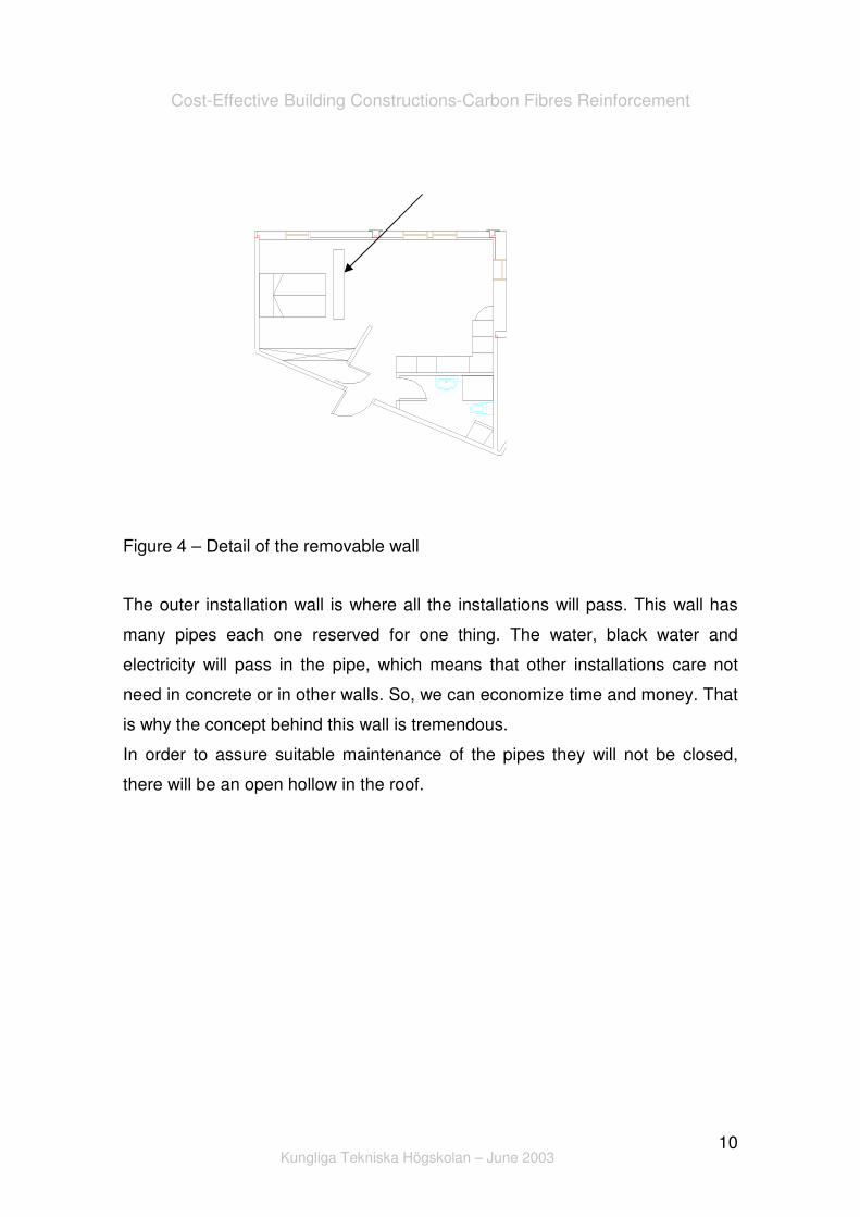
The flat has a removable wall which allows the separation between different
task spaces. The wall is not complete and does not touch the ceiling, which
gives a feeling of a greater space. Additionally users can make their own
division and give it a personal touch. This is an important detail because of the
limited of the apartment (approximately 40 m2).
Cost-Effective Building Constructions-Carbon Fibres Reinforcement
Kungliga Tekniska Högskolan – June 2003
10
Figure 4 – Detail of the removable wall
The outer installation wall is where all the installations will pass. This wall has
many pipes each one reserved for one thing. The water, black water and
electricity will pass in the pipe, which means that other installations care not
need in concrete or in other walls. So, we can economize time and money. That
is why the concept behind this wall is tremendous.
In order to assure suitable maintenance of the pipes they will not be closed,
there will be an open hollow in the roof.

Cost-Effective Building Constructions-Carbon Fibres Reinforcement
Kungliga Tekniska Högskolan – June 2003
11
Figure 5 – Detail of the installation wall
All the walls will be made in a horizontal way and then they will be lift up in order
to economize time. This prefabricate system is more efficient than the traditional
ones and in this case it is possible and advantages to use it.
Figure 6 – Prefabricate walls
Cost-Effective Building Constructions-Carbon Fibres Reinforcement
Kungliga Tekniska Högskolan – June 2003
12
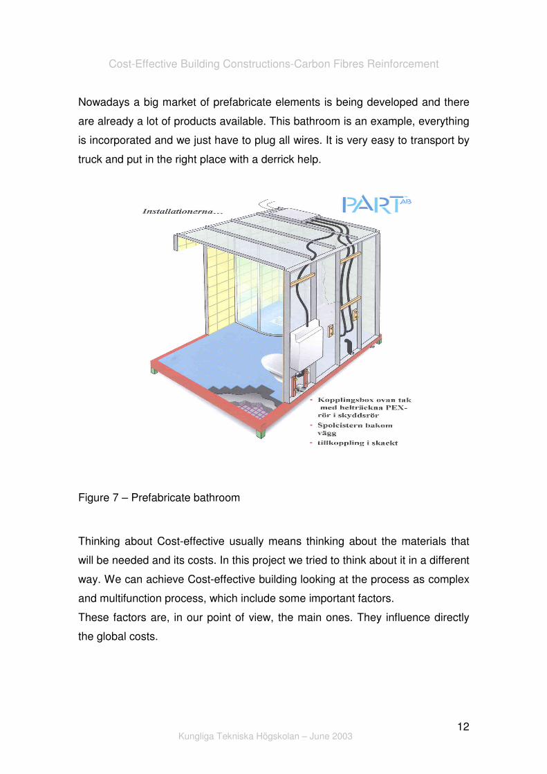
Nowadays a big market of prefabricate elements is being developed and there
are already a lot of products available. This bathroom is an example, everything
is incorporated and we just have to plug all wires. It is very easy to transport by
truck and put in the right place with a derrick help.
Figure 7 – Prefabricate bathroom
Thinking about Cost-effective usually means thinking about the materials that
will be needed and its costs. In this project we tried to think about it in a different
way. We can achieve Cost-effective building looking at the process as complex
and multifunction process, which include some important factors.
These factors are, in our point of view, the main ones. They influence directly
the global costs.

Cost-Effective Building Constructions-Carbon Fibres Reinforcement
Kungliga Tekniska Högskolan – June 2003
13
Figure 8 – Important factors in Global Cost
We are concerned also about the quality, so we want to use good materials. It is
a way of reducing maintenance costs. We do not want save money in elements
materials, but in way and the concept of construction.
4. New concepts of Carbon Fibres Utilization
Laminates for Structural Strengthening
Using carbon fibres to reinforce structures is a technology based on the
worldwide research and development work. It provides a solution for
strengthening problems.
It provides also a great strength, high modulus of elasticity and outstanding
fatigue resistance. It’s a very lightweight non-corrosive material and alkali-
resistant.

Cost-Effective Building Constructions-Carbon Fibres Reinforcement
Kungliga Tekniska Högskolan – June 2003
14
This method is an economic one and requires very short contract times. The
method consists of bonding the carbon fibres strip with the concrete structure
using a high-strength epoxy resin as the adhesive. The carbon fibres strips are
manufactured using a pultrusion process (Figure 9 – Pultrusion Process). The
pultrusion principle is comparable with a continuous press. Normally 24,000
parallel filaments are pulled through the impregnated bath, formed into strips
under heat, and hardened. These strips are uni-directional; the fibres are
oriented only in longitudinal direction. The strip strength in this direction is
proportional to the fibre strength. Some companies are able to sell also bi-
directional strips.
Strips are produced with strengths of approximately 3,000 MPa in the
longitudinal direction and with a thickness of up to 1,5, and widths of up to 150
mm.
The preparation of the bonding surfaces of the strip and concrete is critical. The
strips must have outermost layer of their bonding face, normally matrix-rich,
removed to expose the fibres. Just before the bonding the surface is cleaned
with acetone or special products provided by the company that sells the
product. Sand blasting, high pressure water jets, stoking, or grinding treats the
concrete surface. Shortly before the bonding, it’s cleaned with a vacuum
cleaner. Concrete must be at least 6 weeks old and have a minimum tensile
strength of 1,5 MPa.

Cost-Effective Building Constructions-Carbon Fibres Reinforcement
Kungliga Tekniska Högskolan – June 2003
15
Figure 9 – Pultrusion Process
The pultrusion process is one of the most cost-effective methods for the
production of composite materials. It is a continuous process that produces little
waste material. In the pultrusion process for thermoset resins, fibre
reinforcement is pulled through a resin impregnation area to coat the
reinforcement with resin, through preform plates to begin to shape the
fibre/resin bundle, and through a heated die to cure the resin. A cured part in
the desired shape that requires no further processing exits from the die.
Although the process appears to be simple, numerous process variables such
as pull speed, die temperature, quality of fibre/resin wet-out, and fibre volume
can affect the quality of pultruded composites.

Cost-Effective Building Constructions-Carbon Fibres Reinforcement
Kungliga Tekniska Högskolan – June 2003
16
Deficient bridges
Many bridges, especially in US are made of reinforced concrete and were
designed in accordance with older codes to accommodate traffic loads smaller
than currently permitted. Moreover, most of these structures were designed for
gravity loads only, with no consideration of seismic vulnerability. In order to
minimize the cost, time of construction and traffic disturbance, a new technology
of carbon fibre laminate system, is often used.
Smart Concrete
Concrete has been widely used for many years as a composite material for
various types of structures. One of the weaknesses of concrete is that it cannot
withstand tension, which can cause cracks easily. There has been a huge
demand to monitor concrete structures cracking and preventing them from
propagating further.
A smart concrete was developed (by Dr. Deborah) in order to minimize this
problems. Smart concrete is reinforced by carbon fibre as much as 0, 2% to 0,
5% of volume to increase it sense ability to strain or stress while still has good
mechanical properties.
By adding small amount of short carbon fibre into concrete with a conventional
concrete mixer, the electrical resistance of concrete increase in response to
strain and stress. As the concrete is deformed or stressed, the bond between
the fibre and the cement matrix is affected, which means that the electrical
properties receptivity of concrete is affected to. Strain is detected through
measurement of the electrical resistance, so smart concrete has the ability to
sense tiny structural flaws before they became significant.
The presence of carbon fibres into the concrete also controls the cracking, so
the cracks don’t propagate catastrophically, as in the case of conventional
concrete.

Cost-Effective Building Constructions-Carbon Fibres Reinforcement
Kungliga Tekniska Högskolan – June 2003
17
This technology has been through extensive laboratory testing, however it still
needs field-testing and it is not available in the market.
The use of smart concrete is proposed in:
• Highway – The highway made by this concrete could be able to
determine were each vehicle was, and what its weight and speed were;
• For real-time vibrations sensing of bridges or other highway structures;
• In buildings, to damped vibrations or reduce earthquake damage.
Ultralightweight exterior precast panels
The weight of the exterior may in some cases account for up to 10 % of the total
weight of the building, which has a great impact on structural planning. Reduce
the weight and increasing the strength of exterior precast panels (made of
concrete) is very important in terms of answering the needs of ensuring the
safety of buildings in respect of earthquakes and rationalizing construction.
There are tree types of concrete that are being used to reduce the weight.
• Ultralightweight concrete;
• Vinylon fibre reinforcement ultralightweight concrete;
• DSCF (Carbon Fibre Spray Mortar).
The DSCF is a system that consists in spraying carbon fibres with mortar. By
spraying carbon fibres, a marked improvement in bending strength has been
achieved, making the possible to dramatically reduce panel thickness and
weight.
This kind of technology is better in all properties when compared with the other
two (ultralightweight concrete and vinylon fibre reinforcement ultralightweight
concrete).
Cost-Effective Building Constructions-Carbon Fibres Reinforcement
Kungliga Tekniska Högskolan – June 2003
18
New structural material
A new material on the construction industry market is the so called Fibre
Reinforced Plastics (FRP). Some technologies have been developed using this
material for example:
Structural shapes – FRP can be made into constant cross-section
structural shapes through the pultrusion process of manufacturing. Almost any
shape or combinations of shapes can be created with pultrusion process
(Figure 9 – Pultrusion Process). This shapes have good strength
characteristics, are very light, require little or no maintenance and can be
erected easily and quickly.
Prestressing and post-tensioning tendon - Generally, concrete has been
prestressed and post-tensioned with high-strength steel cables to help it resist
tensile stresses, reduce cracking and deflections. However, FRP has many
characteristics that make it a better candidate for the tendons concrete
structures compared to steel, including high tensile strength, flexibility with
regard to size and shape, light weight and corrosion resistance. FRP does not
suffer any adverse affects from exposure to environmental factors, so post-
tensioning can be greatly simplified by allowing the cables outside of the
structure itself. With this new application the concrete will not have to
accommodate post-tensioning ducts thus reducing concrete fabrication time,
and process of installing the cables is much simpler.
However there some characteristics are not fully understood, for example low
modulus of elasticity, creep and fatigue.
That is one of the reasons why the currently building codes do not allow the use
of FRP materials.
Other studies about special concrete

Cost-Effective Building Constructions-Carbon Fibres Reinforcement
Kungliga Tekniska Högskolan – June 2003
19
Dr. Krstulovic-Opara (an assistant professor of civil engineering at North
Carolina State University) is developing a high performance fibre-reinforced
concrete (HPFRC) that prevents the separation of large pieces of concrete from
a structure.
When the concrete does fail, the pieces remain stuck together, held in place by
the stainless steel fibres. The pieces that separate from the structure are much
smaller and less likely to cause injury.
Is known that concrete structures will eventually fail, the goal is extend the
length of time it takes for the structure to fail and control how it fails.
During extreme structural stress, such as an explosion or an earthquake,
conventional concrete breaks apart in large chunks and separates from the
steel reinforcing bars (called rebar). So, large slabs and chunks of concrete fall,
crushing anything below.
Dr. Krstulovic-Opara has been developing the high performance system using
fibre mats injected with special concrete slurry, a mixture of concrete, aggregate
and liquids that adds tensile strength, durability, and energy absorbing
properties to the concrete.
The mats are made of recycled stainless steel fibres and come in large rolls that
can be cut and shaped to fit any space or use.
This new concrete composite has been used to strengthen structures against
earthquakes in laboratory models.
Nowadays a team from this university is developing a new structural system
that would best employ these advanced features to increase impact resistance
to explosive blasts as well.
In addition to its safety features, the fibre-reinforced concrete system may
change the way that buildings are built, strengthened or repaired.

Cost-Effective Building Constructions-Carbon Fibres Reinforcement
Kungliga Tekniska Högskolan – June 2003
20
Today, building a concrete structure means workers have to bend steel rebars
into frames, build wooden or metal forms around the frames, add concrete and,
once the concrete has had time to cure, remove the forms.
System developed by Dr. Krstulovic-Opara can be used as both frame and form
for structural support of the building. Workers simply shape the fibre mat rolls
and inject them with concrete slurry. The system is designed to use traditional
concrete construction equipment with minimal modifications.
For renovations or repairs, workers can wrap the fibre mats around existing
columns and beams or use the fibre mats as forms and fill them with
conventional concrete. The result is a support beam or column that is super
strong and more durable than conventional concrete alone.
The system eliminates much of the physical labour and most of the labour
costs. With its low cost and easy construction, the new material could be used
in new construction or renovations.
Other systems of reinforcing concrete are being researched and used - steel
fibres, carbon fibres, polypropylene fibres, concrete mixed with aramid fibres
and vinylester resin, and concrete modified with silicates. But this is the first
system to make use of fibre mats that can strengthen and shape the material.
According to Dr. Krstulovic-Opara this new concrete can reduce the cost of
repairing existing concrete structures and give them added strength and
durability. And because of its design, it can easily be transferred from the
laboratory to everyday use.
New constructions
There are few examples of new constructions with this technology. One current
examples involves the installation of an carbon fibre reinforced concrete bridge
in St. James, MO. Work is in progress in order to replace a traditional reinforced

Cost-Effective Building Constructions-Carbon Fibres Reinforcement
Kungliga Tekniska Högskolan – June 2003
21
concrete slab bridge with a multi-panel concrete bridge reinforced with carbon
fibre rods for both shear and flexure.
5. Sika Materials
In course of this work I tried find some companies whose work was carbon
fibres reinforcement. One of the biggest companies in the international market,
nowadays, is Sika. They work in varied fields and are considered an expert in
this technology. Their philosophy is in accordance with ours, they think: “In the
battle for market share and the fight against exploding production costs,
innovative solutions are often the key to survival”.
From this moment I will use Sika products and all characteristics are based in
their products.
They have a huge variety of products, but to reinforce damage structures they
usually advise their Heavy-Duty CFRP Strengthening System.
The system alluded is used to reinforce concrete, masonry, stonework, steel
aluminium and timber, and incorporate two components:
• Sika CarboDur CFRP plates;
• Sikadur – 30 adhesive for bonding reinforcement.
Main function of this system is bonding of similar or different materials to
transfer high loads and replace other joining methods like welding, screwing or
riveting. Depending on the design, this system do not only bond parts together
but it also fulfil additional functions, such as:
• strengthening and reinforcing structures with Carbodur strips;
• dampening by increasing stiffness to create stronger structures to shift
the resonance frequency towards higher frequencies;
• Protection, since adhesives show excellent adhesion on metal substrates
thus preventing corrosion.

Cost-Effective Building Constructions-Carbon Fibres Reinforcement
Kungliga Tekniska Högskolan – June 2003
22
Sika Products – Its Applications Nowadays
This system is also used to reinforce structure when some problems occur.
Problems such as:
• Load increases due to higher live loads, increased wheel loads,
installation of heavy machinery, or vibration;
• Modification of structural system by eliminating walls or columns, or
opening through slabs;
• Improvements in suitability for use due to limitation of deflections,
reduction of stress in steel reinforcement and/or reduction of crack;
• Damage to structural parts to aging of construction materials or fire
damage, corrosion of the steel reinforcement, and/or impact of vehicles;
• Errors in planning or construction because of insufficient design
dimensions and/or insufficient reinforcing steel.
Products Advantages
Some advantages of this product:
• Low in weight
• Available in any length, no joints required
• Low overall thickness
• Easy to transport (rolls)
• No preparation of the Sika CarboDur-laminates
• Laminate intersections are simple
• Economical application
• No heavy handling and installation equipment
• Very high strength
• Available in various modulus of elasticity
• Outstanding fatigue resistance
• High alkali resistance

Cost-Effective Building Constructions-Carbon Fibres Reinforcement
Kungliga Tekniska Högskolan – June 2003
23
• No corrosion
Products Preparation
Concrete
Blast clean, shot blast or use other approved mechanical means to provide an
open roughened texture. The concrete should have at least 3 to 6 weeks
(depending of the weather).
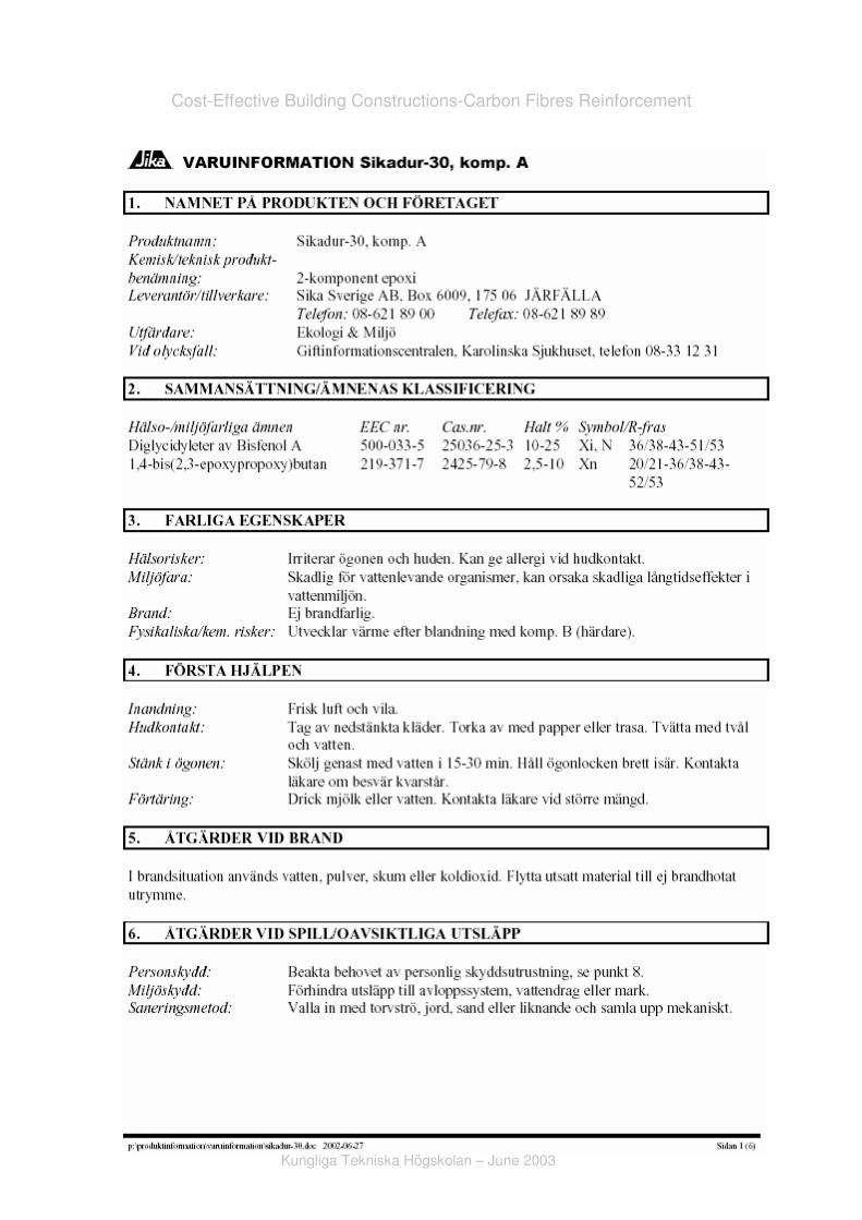
Sikadur 30
Pre-mix each component in a slow way in order to get a better result. Empty
component B into A component pail or add component B in the correct mix ratio
to component A. Mix for 3 min using a low-speed drill (300-450 rpm) to minimize
air entrapment. Use an Exomixer type mixing paddle (recommended model).
During the mixing operation, scrape down the sides and bottom of the pail with
a flat or straight edge trowel at least once to ensure thorough mixing. Upon
completion of mixing, Sikadur 30 should be uniform in colour. Mix only that
quantity you can use within its pot life.
Sika CarboDur
Surface should be wiped clean using an appropriate cleaner. Using a clean
white cloth, wipe down the side receiving the adhesive (this side is not labeled)
with acetone (or other product special for do it) until all residual carbon dust is
removed (i.e. white cloth remains white after wiping the laminate). In case
where the design requires “stacking” of the strips, the bottom surface of the strip
(labeled) should be lightly sanded (emery paper type 180) prior to the second
strip application.

Cost-Effective Building Constructions-Carbon Fibres Reinforcement
Kungliga Tekniska Högskolan – June 2003
24
Surface Preparation
Surface must be clean and sound. It may be dry or damp, but free of standing
water. Remove dust, laitance, grease, curing compounds, impregnations,
waxes, foreign particles, disintegrated materials, and other bond inhibiting
materials from the surface. Existing uneven surfaces must be filled with an
appropriate repair mortar (i.e. Sikadur 30 with the addition of 1 part sand) in
order to achieve the correct bond. The adhesive strength of the concrete must
be verified after surface preparation by random pull off testing (ACI 503R) at the
discretion of the engineer. Minimum tensile strength: 1.5 MPa with concrete
substrate failure.
Planeness of substrate can be checked with a metal batten. Tolerance for 2 m
length: max.10 mm, or 2.5 mm for 50 cm length respectively.
Products Application
Apply the neat mixed Sikadur 30 onto the concrete with a trowel or spatula to
nominal thickness of 1.5 mm. Put the Sika CarboDur laminate on a table and
cleans it with a special cleaner. Apply the mixed Sikadur 30 onto the CarboDur
laminate with a ‘roof shaped’ spatula to a nominal thickness of 1.5 mm. Within
the epoxy open time and depending on the temperature, place CarboDur
laminate onto the concrete surface. Using a hard rubber roller, press the
laminate into the epoxy resin until the adhesive is force out on both sides.
Remove excess adhesive. Glue line should not exceed 3 mm. The laminate
must not be disturbed for a minimum of 24 h. The epoxy will reach its design
strength after 7 days.
The glue final resistance and all system should be verified in accordance with
appropriate codes and standards.

Cost-Effective Building Constructions-Carbon Fibres Reinforcement
Kungliga Tekniska Högskolan – June 2003
25
Limitations
Design calculations must be made and certified by an independent licensed
professional engineer. Sika cannot, and will not determine the locations,
spacing and orientation of the CarboDur System on the actual projects.
CarboDur has no plastic deformation reserve. Therefore, the maximum bending
resistance of a strengthened section is reached when laminate failure occurs
during steel yield and before concrete failure. The mode of failure is influenced
by the laminate cross-section. To limit crack widths and deformation, the yield
point should not be reached in the reinforcing bars in service conditions. Any
shear crack must be prevented from causing displacement on the strengthened
surface and shearing of the laminate. Stress and deformation calculations can
be made by the normal methods. They should be verified in accordance with
appropriate codes and standards.
6. Design and some Building Details
As was told before, I am trying to find the stress in the slabs in order to
understand if it is possible, or not, to use carbon fibres. In order to have an idea
of the structural behaviour of the building I started to model it in a Finite Element
Program called Sap 2000. I modelled it according with some data and values
given to me. The information of the building’s dimensions and also the elements
characteristics are presented bellow:
Beam (C-Profile)
Column (80 mmx120 mm and thickness of 12 mm)
Hollow Core Slabs (thickness of 320 mm)

Cost-Effective Building Constructions-Carbon Fibres Reinforcement
Kungliga Tekniska Högskolan – June 2003
26
Figure 10 – Building Dimensions
In this model I can see the elevator, stairs, the concrete wall in the edges and
the hollow core slabs that were modelled as shell elements.

Cost-Effective Building Constructions-Carbon Fibres Reinforcement
Kungliga Tekniska Högskolan – June 2003
27
Figure 11 – Building Model (SAP 2000)
Using the Loads Combinations bellow and applied them in our structure I could
see the deformed shape of it and have an idea of the stresses existing.
Sdw = γgSg+γq (Sw+ψ0qSq)
Sdq = γgSg+γq (Sq+ψ0wSw)
Sdw – Design Value with Wind as Main Load;
Sdq – Design Value with Imp. Loads as Main Load;
Sg – Self-Weight Load;
Sw – Wind Load;
Sq – Imposed Load;
γq,γg – Safety Factors (Portuguese’s).

Cost-Effective Building Constructions-Carbon Fibres Reinforcement
Kungliga Tekniska Högskolan – June 2003
28
The deformed shape is very useful, understanding it is the first step to
understand all structural behaviour of the building.
Figure 12 – Building Deformed Shape
Other view of the Deformed Shape is presented below:

Cost-Effective Building Constructions-Carbon Fibres Reinforcement
Kungliga Tekniska Högskolan – June 2003
29
Figure 13 – Building Deformed Shape (Other View)
As I was expecting the structure has a symmetrical behaviour (in Y direction)
and it is easy to understand why. The concrete strong wall (in the edge) and the
elevator box are working as fixed points and as a support. So, I simplified the
building structure and modelled it as a just supported beam. As a simplification,
and because of the building’s symmetry, I decided start to study just one side of
it.
The worst direction to apply the loads is the one presented below, because in
the other case the wind loads assume lower values (because I would have to
introduce the sin 30 and cos 30).The directions of the loads is not relevant. If I
had chosen the opposite direction all stresses would come with symmetrical
sign (positive ones would be negative and the negative would pass to positive)
but with same values. The simplified model is:

Cost-Effective Building Constructions-Carbon Fibres Reinforcement
Kungliga Tekniska Högskolan – June 2003
30
Figure 14 – Simple Structural Model
The Swedish code has some characteristics loads values for usual buildings
and I started with that ones. The Eurocode has different load values however
the Swedish ones are reasonable.
Loads
Self-weight (kN/m²) 4,00
Self-weight (roof) (kN/m²) 2,50
Imposed Loads (kN/m²) 2,00
Wind (kN/m²) 0,70
Snow (kN/m²) 1,50
Table 1 – Characteristics Loads
This building will be constructed in steel and concrete. The columns will be in
steel and the slabs in concrete. In order to get shorter the construction time we

Cost-Effective Building Constructions-Carbon Fibres Reinforcement
Kungliga Tekniska Högskolan – June 2003
31
are using pre-fabrication elements. So, everything will be transported and built
in the right place. Because of this building detail I had to think about the
Imperfections Loads. It is important mention that vertical loads are supported by
the steel columns and are not studied in this project. I used them to calculate
the horizontal force resultant from the imperfection loads.
Imperfections Loads
In reality structures are not perfect, there are imperfections that arise from the
manufacturing processes such as members being initially not perfectly straight,
residual stresses, material defects and so on. We can extend our stability
analysis further to cover this class of problem.
It is useful to distinguish two types of imperfections, one associated with the
physical structure, the other with the computational model.
The first is Physical Imperfection that may be categorized into fabrication and
load imperfections. And the second one is Numerical Imperfection. This type of
imperfection may be incorporated in the computational model for various
reasons.
Real structures inevitably carry geometric imperfections inherent in their
manufacture. In addition, loads on structural members that carry primarily
compressive loads, such as columns and cylindrical shells, are not necessarily
centred.
The advantage of the imperfections (loads) is that you can work with perfect
geometry in the software and still make a safe design not neglecting the
imperfections of a structure.
We can estimate the influence of existing imperfections of each structure that
result in additional horizontal loads.

Cost-Effective Building Constructions-Carbon Fibres Reinforcement
Kungliga Tekniska Högskolan – June 2003
32
Wind
In order to quantify the wind loads we should look at the place where the
building will be built. Many characteristics are dependent of the build’s place.
Some regions are more exposed to wind like valleys or estuaries, and it is
important also know if it will be built in an urbane or a rural area. The variation
of wind’s speed with height is dependent of the terrain aerodynamics roughness
and is related with the obstacles dimensions and its distribution. These
obstacles have influence in the draining behaviour. Consequently, the build’s
localization is extremely important.
The building aerodynamics and geometrical characteristics are also decisive. In
the usual cases the determination of wind stress can be made, in a simple way,
by applying static pressures. This static pressure can be esteemed as wind’s
pressure dynamics times special coefficients.
The wind’s pressure dynamics is a function which is dependent of the building’s
height. In spite of its parabolic behaviour is assumed that for low buildings the
wind load is constant.
Calculations
When I think in the stabilization of the hollow core slabs I have to think in the
horizontal loads which are the Imperfections and the Wind.
To notch up the Imperfections Effects I estimated a horizontal load, but I did it in
a simplify way. I defined V1 and V2 as the resultant vertical force in each floor.
The Geometric Characteristics and the Safety Factors are:
Cost-Effective Building Constructions-Carbon Fibres Reinforcement
Kungliga Tekniska Högskolan – June 2003
33
Geometric
Characteristics Safety Factors
Hf (m) 3,10 γg 1,35
Lx (m) 31,25 γq 1,50
Ly (m) 18,80 ψο (wind) 0,60
L (m) 36,00 ψο (imp.loads) 0,70
D (m) 9,00 ψο (snow) 0,60
α (º) 30,00
φ (º) 0,004
Area (m²) 413,10
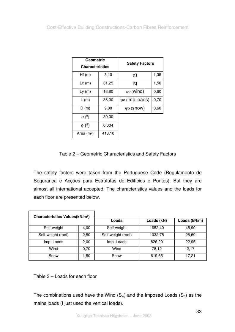
Table 2 – Geometric Characteristics and Safety Factors
The safety factors were taken from the Portuguese Code (Regulamento de
Segurança e Acções para Estrututas de Edifícios e Pontes). But they are
almost all international accepted. The characteristics values and the loads for
each floor are presented below.
Characteristics Values(kN/m²)
Loads Loads (kN) Loads (kN/m)
Self-weight 4,00 Self-weight 1652,40 45,90
Self-weight (roof) 2,50 Self-weight (roof) 1032,75 28,69
Imp. Loads 2,00 Imp. Loads 826,20 22,95
Wind 0,70 Wind 78,12 2,17
Snow 1,50 Snow 619,65 17,21
Table 3 – Loads for each floor
The combinations used have the Wind (Sw) and the Imposed Loads (Sq) as the
mains loads (I just used the vertical loads).
Cost-Effective Building Constructions-Carbon Fibres Reinforcement
Kungliga Tekniska Högskolan – June 2003
34
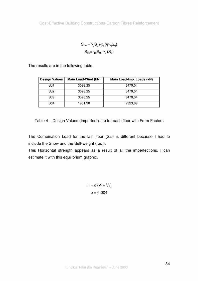
Sdw = γgSg+γq (ψ0qSq)
Sdq= γgSg+γq (Sq)
The results are in the following table.
Design Values Main Load-Wind (kN) Main Load-Imp. Loads (kN)
Sd1 3098,25 3470,04
Sd2 3098,25 3470,04
Sd3 3098,25 3470,04
Sd4 1951,90 2323,69
Table 4 – Design Values (Imperfections) for each floor with Form Factors
The Combination Load for the last floor (Sd4) is different because I had to
include the Snow and the Self-weight (roof).
This Horizontal strength appears as a result of all the imperfections. I can
estimate it with this equilibrium graphic.
H = φ (V1+ V2)
φ = 0,004

Cost-Effective Building Constructions-Carbon Fibres Reinforcement
Kungliga Tekniska Högskolan – June 2003
35
Figure 15 – Horizontal resultant of Imperfections
Figure 16 – Equivalent Angle
The first floor is worst case, as illustrated.
V1 = � Sdi i=2, 3, 4
V2 = � Sdi i=1, 2, 3, 4
i – Floor;

Cost-Effective Building Constructions-Carbon Fibres Reinforcement
Kungliga Tekniska Högskolan – June 2003
36
Main Load-Wind
Imperfections 1º Floor 2º Floor 3º Floor 4º Floor
V1 (kN) 8148,40 5050,15 1951,90 0,00
V2 (kN) 11246,65 8148,40 5050,15 1951,90
H (kN) 77,58 52,79 28,01 7,81
H (kN/m) 2,16 1,47 0,78 0,22
Main Load-Imp. Loads
Imperfections 1º Floor 2º Floor 3º Floor 4º Floor
V1 (kN) 9263,77 5793,73 2323,69 0,00
V2 (kN) 12733,81 9263,77 5793,73 2323,69
H (kN) 87,99 60,23 32,47 9,29
H (kN/m) 2,44 1,67 0,90 0,26
Table 5 – Horizontal Load (Imperfections)
I had considered the Wind as a constant load what is not true, because the wind
has a parabolic behaviour. However, for low buildings this simplification is valid
and conservative (see Figure 16). In this case the building has just four floors
which mean that its height is approximately 13,5 meters.
The Loads Combinations for the horizontal load are:
Sdw = γq Sw
Sdqi= γq (ψ0qw Sw)
Design Values Main Load-Wind (kN) Main Load-Imp. Loads (kN)
Wind 3,26 1,95
Table 6 – Wind Load

Cost-Effective Building Constructions-Carbon Fibres Reinforcement
Kungliga Tekniska Högskolan – June 2003
37
Figure 17 – Wind Parabolic Curve
Thinking in both loads at same time (for example Wind and Imperfections when
Wind is Main Load it came 3,26+2,16=5,41) I am able to calculate the stresses
in my model (just support beam).
Main Load-Wind Main Load-Imp. Loads
Horizontal
Forces Wind+Imperfections
Total Horizontal
Force (kN/m) Wind+Imperfections
Total Horizontal
Force (kN/m)
M (kNm) 876,42 5,41 712,34 4,40
S (kN) 97,38 79,15
A (kN) 56,22 45,70
Table 7 – Design Stresses
Where,
M – Bending Moment;
S – Shear Force;
A – Axial Force.

Cost-Effective Building Constructions-Carbon Fibres Reinforcement
Kungliga Tekniska Högskolan – June 2003
38
As we can see in the design values table the effect of the wind is much bigger
when the wind is the main load.
Now, I know the stress caused by all Horizontal Forces (Wind+Imperfections).
Longitudinal Direction
The Axial Force appears in order to guarantee the equilibrium, because the
strong wall supports the strength mostly in Y direction, like is showed in the next
picture:
Figure 18 – The Equilibrium in the concrete walls
Where F represents the strength supported by the concrete strong wall, S is the
Shear Force and A the Axial Force.
The figure bellow shows the simplified system and the stress calculated.

Cost-Effective Building Constructions-Carbon Fibres Reinforcement
Kungliga Tekniska Högskolan – June 2003
39
Figure 19 –Equivalent Stresses
This means that I have compression strength in one part of the building and a
tension in the other part.
2A
DM
T +=
2A
DM
C −=
T – Tension Strength
C – Compression
M – Bending Moment
D – Distance between the Tension and Compression
A – Axial Force

Cost-Effective Building Constructions-Carbon Fibres Reinforcement
Kungliga Tekniska Högskolan – June 2003
40
Compression (kN) Tension(kN)
M-A M+A
69,27 125,49
Table 8 – Compression and Tension (Longitudinal Direction)
With these values I am able to decide which material I can use. Simple
calculations show me the area that I will need of carbon fibres, depending of the
material chosen. As I explained before I am using Sika products and all the
technical data are available in the Annex.
Tensile Strength (Min. Value) (MPa)*
XS S M UH**
Safety factor 2200,00 2800,00 2800,00 1800,00
� 1,50 1466,67 1866,67 1866,67 1200,00
Table 9 – Tensile Strength and Safety Factor
With this simple equation I can know the area needed.
Ts= ϕS/Sc
Ts – Tensile Strength;
ϕ - Safety Factor;
S – Shear Force;
Sc – Area Needed of Carbon Fibres.
The abbreviations XS, S, M and UH means Sika CarboDur XS, Sika CarboDur
S, Sika CarboDur M, Sika CarboDur UH. These products are sold by Sika and
all my calculations had these products as base.

Cost-Effective Building Constructions-Carbon Fibres Reinforcement
Kungliga Tekniska Högskolan – June 2003
41
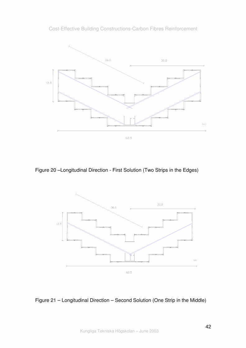
In order to study the best solution to this project in a structural and economical
point of view I decided present two different solutions. The first one is use two
strips of laminates in the building edges (in the longitudinal direction) and the
other one is use just one strip in the middle.
Two Different Solutions
In the Longitudinal Direction, I have this area needed.
Longitudinal Direction of Fibres
Area (mm²)
XS S M UH** 2 Strip
85,56 67,23 67,23 104,58
XS1014 S612 M514 -
XS S M UH 1 Strip
151,96 119,40 119,40 185,73
XS1214 S1012 M914 -
Table 10 – Longitudinal Direction (Different materials and solutions)
According with the technical data given (see Annex) the products that should be
used are Sika CarboDur XS1014, Sika CarboDur S612 and Sika CarboDur
M514 in first solution and Sika CarboDur XS1214, Sika CarboDur S1012 and
Sika CarboDur M914 in the second solution.
All this materials are able to be applied in our structure however the costs
analysis will show which one is the best solution.
Cost-Effective Building Constructions-Carbon Fibres Reinforcement
Kungliga Tekniska Högskolan – June 2003
42
Figure 20 –Longitudinal Direction - First Solution (Two Strips in the Edges)
Figure 21 – Longitudinal Direction – Second Solution (One Strip in the Middle)

Cost-Effective Building Constructions-Carbon Fibres Reinforcement
Kungliga Tekniska Högskolan – June 2003
43
Transversal Direction
As is known the carbon fibres do not resist so well in the perpendicular direction
so I investigate the stress in each section where I can need it. I had to
determine the strength in the joint between the slabs, and understand if the
compression calculated is enough to the stabilization, or if I need to reinforce
the structure with carbon fibres.
Figure 22 – Joints studied (Transversal Direction)
The joint is able to support part of the strength, this is possible due to the friction
forces. Nevertheless, there is roughness which is written up by a factor (µ).
This behaviour makes sense only when compression strength works.

Cost-Effective Building Constructions-Carbon Fibres Reinforcement
Kungliga Tekniska Högskolan – June 2003
44
Figure 23 – Compression
So,����Sj = S/cos α
Cn = Sj/ µ
Cp=M/D-A/2
Sj - Strength in the joint between two slabs;
Cn – Necessary Compression;
Cp - Possible compression;
µ - Roughness Factor;
α – Angle (30º).
I will need Carbon Fibres if: Cn>Cp
D (m) 9,00
� 0,70

Cost-Effective Building Constructions-Carbon Fibres Reinforcement
Kungliga Tekniska Högskolan – June 2003
45
x (m) S(kN) Sj(kN) Cn (kN) Cp (kN)
Carbon
Fibres
Area (mm²)
0,00 97,38 112,44 160,64 28,11 CF 66,40 52,17 52,17 81,15
8,30 52,48 60,60 86,56 40,99 CF 35,78 28,11 28,11 43,73
16,60 7,57 8,75 12,49 68,68 NO - - - -
18,00 0,00 0,00 0,00 69,27 NO - - - -
24,90 -37,33 -43,10 61,58 68,68 NO - - - -
33,20 -82,23 -94,95 135,65 40,99 CF 56,07 44,05 44,05 68,53
36,00 -97,38 -112,44 160,64 28,11 CF 66,40 52,17 52,17 81,15
XS514 S512 M514 -
Table 11 – Transversal Direction – First Solution (Two Strips in the Edges)
For the Second Solution the value of D will change.
D (m) 4,50
� 0,70
x (m) S(kN) Sj(kN) Cn (kN) Cp (kN)
Carbon
Fibres Area (mm²)
0,00 97,38 112,44 160,64 28,11 CF 66,40 52,17 52,17 81,15
8,30 52,48 60,60 86,56 110,09 NO 35,78 28,11 28,11 43,73
16,60 7,57 8,75 12,49 165,47 NO - - - -
18,00 0,00 0,00 0,00 69,27 NO - - - -
24,90 -37,33 -43,10 61,58 165,47 NO - - - -
33,20 -82,23 -94,95 135,65 110,09 CF 56,07 44,05 44,05 68,53
36,00 -97,38 -112,44 160,64 28,11 CF 66,40 52,17 52,17 81,15
XS514 S512 M514 -
Table 12 - Transversal Direction – Second Solution (One Strip in the Middle)

Cost-Effective Building Constructions-Carbon Fibres Reinforcement
Kungliga Tekniska Högskolan – June 2003
46
CF Use Carbon Fibres
NO Do not use Carbon Fibres
Using the same reasoning as I used for the Longitudinal Direction, I can know
the area of carbon fibres that I will need and also the material that I should use
in each section.
I can use Sika CarboDur XS514, Sika CarboDur S512 and Sika CarboDur
M514 in both solutions (as it is possible see in the tables above).
Figure 24 – Transversal Direction – First Solution (Two Strips in the Edges)

Cost-Effective Building Constructions-Carbon Fibres Reinforcement
Kungliga Tekniska Högskolan – June 2003
47
Figure 25 – Transversal Direction – Second Solution (One Strip in the Middle)
In this point of the work I know where and which material I should use.
The draws above show us the both solutions.
7. Costs
The prices, per lineal metre, for these products were given by Sika, Sweden
and are presented below. The prices include relevant factors chosen to the
Costs Analysis such as Material (Carbon Fibres and Adhesive), Material
Application and Fire Protection.
The Transportation costs were not including in this study because they are not
important compared with the other prices.
The price for the First Solution per linear metre is presented bellow:

Cost-Effective Building Constructions-Carbon Fibres Reinforcement
Kungliga Tekniska Högskolan – June 2003
48
Longitudinal Direction of Fibres
Prices (SEK/m) Two Strip in the Edges
Material
Carbon
Fibres
Material
Adhesive
Material
Application
Fire Prot
Appl. Total
Sika CarboDur XS1014 220 30 200 100 550
Sika CarboDur S612 170 18 200 100 488
Sika CarboDur M514 300 15 200 100 615
Total Cost
(SEK/m²)
Normal Direction of Fibres
Prices (SEK/m) 127,18 kr
Material
Carbon
Fibres
Material
Adhesive Application
Fire Prot.
Appl. Total
Sika CarboDur XS514 120 15 200 100 435
Sika CarboDur S512 150 15 200 100 465
Sika CarboDur M514 300 15 200 100 615
Table 13 – Cost for the First Solution
And for the Second Solution the table shows:
Longitudinal Direction of Fibres
Prices (SEK/m) One Strip in the Middle
Material
Carbon
Fibres
Material
Adhesive Application
Fire Prot.
Appl. Total
Sika CarboDur XS1214 270 36 200 100 606
Sika CarboDur S1012 220 30 200 100 550
Sika CarboDur M914 510 27 200 100 837
Total Cost
(SEK/m²)
Normal Direction of Fibres
Prices (SEK/m) 79,52 kr
Material
Carbon
Fibres
Material
Adhesive Application
Fire Prot.
Appl. Total
Sika CarboDur XS514 120 15 200 100 435
Sika CarboDur S512 150 15 200 100 465
Sika CarboDur M514 300 15 200 100 615
Table 14 – Cost for the Second Solution

Cost-Effective Building Constructions-Carbon Fibres Reinforcement
Kungliga Tekniska Högskolan – June 2003
49
These values can give us an idea about the costs for this part of the project
(using carbon fibres).
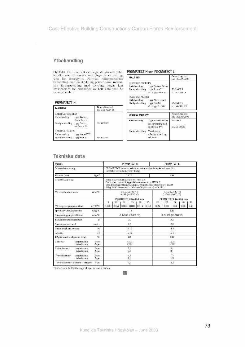
The fire protection is very important when it is used this kind of technology. The
Carbon Fibres need to be protect, however in this case the floor that will be
applied is fire resistant too. Depending of which floor and “how much”
resistance it will be, the price for the material of fire protection will change. It is
easy to understand that the price of that material is defined according the
quality of the material and how secure we want that our building would be. The
fire protection it will be applied as it is shown in the picture. Technical data are
present in the Annex.
Figure 26 – Fire Protection
Cost-Effective Building Constructions-Carbon Fibres Reinforcement
Kungliga Tekniska Högskolan – June 2003
50
8. The Best Solution
One of the biggest and more important factors which are decisive to choose the
best solution is, of course, the price.
But to choose the best solution I looked to some other important aspects and
not only to the price. The structural behaviour is also one of the most important
and relevant factors when the best solution has to be chosen.
The costs for this technology are divided in:
• Materials
Sika CarboDur ;
Sikadur 30.
• Application
Price;
Time (Information not available).
• Fire Protection
• Transport
• Structural Behaviour
The price for the different materials depends mainly of its technical
characteristics.
Data sources tell that the application costs increase depending how difficult is to
get to the application’s places. Our structure will have laminates in the top of the
hollow core slabs, which are completely plane and horizontal, so the application
costs can be low. Other options it would be apply the material not on the floor
but in the ceiling, however it would be much more difficult to the workers, which
means that the price would be bigger. About the application time it was not
possible to know (approximately) how many hours or minutes it would be
needed to apply one metre of Sika CarboDur and of course Sikadur 30. The

Cost-Effective Building Constructions-Carbon Fibres Reinforcement
Kungliga Tekniska Högskolan – June 2003
51
Fire Protection will depend of which kind of floor will be apply, however the cost
analysis includes the application cost of it.
The transportation cost is not important in this context, because it is a low value
compared with global costs. Therefore, it is easy to understand that I am talking
in a reason of 2:1, so the cost for transportation of two laminates (First Solution)
can be approximately the double (of Second Solution).
In a structural point if view the solution with two Sika CarboDur laminate in the
both edges of the building is more interesting. Is in corners of the building where
are the critical points that is why the material is more efficient there.
The both laminates can guarantee a bigger security, because if something
happens to one of the laminates there is the other one which can stabilize the
slabs, until the problem can be solved.
However I can not forget the aim of this project which is reduce the production
cost of multifamily houses. According to this aim and knowing that the security
and comfort are assured, the best solution is apply one strip in the middle.
Figure 27 – Important Factor to choose the Best Solution
Cost-Effective Building Constructions-Carbon Fibres Reinforcement
Kungliga Tekniska Högskolan – June 2003
52
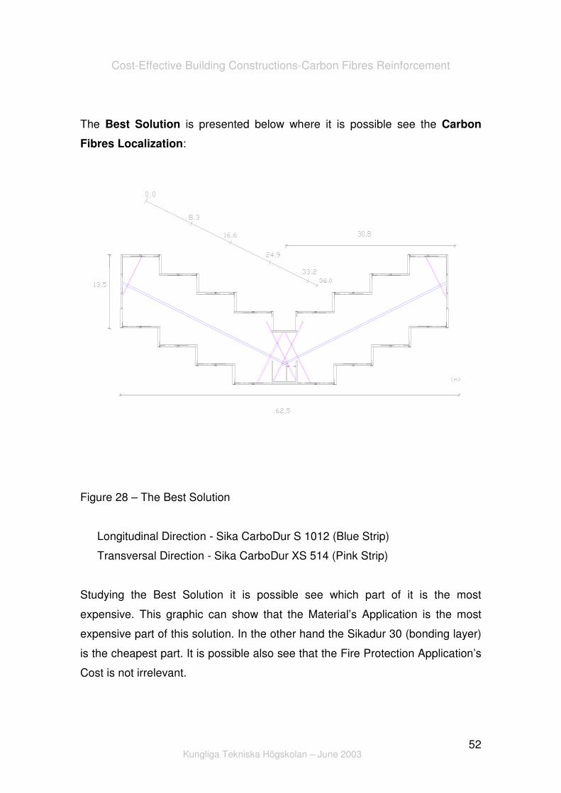
The Best Solution is presented below where it is possible see the Carbon
Fibres Localization:
Figure 28 – The Best Solution
Longitudinal Direction - Sika CarboDur S 1012 (Blue Strip)
Transversal Direction - Sika CarboDur XS 514 (Pink Strip)
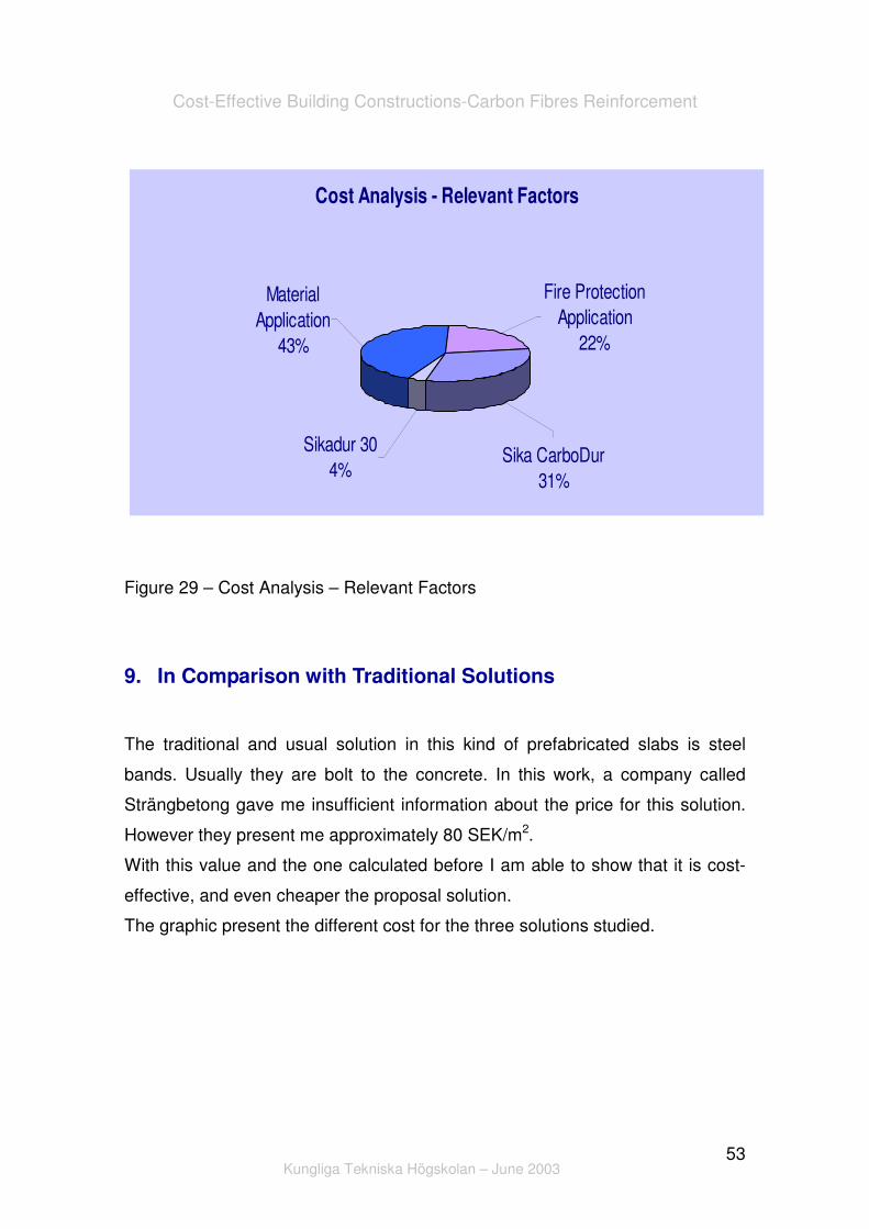
Studying the Best Solution it is possible see which part of it is the most
expensive. This graphic can show that the Material’s Application is the most
expensive part of this solution. In the other hand the Sikadur 30 (bonding layer)
is the cheapest part. It is possible also see that the Fire Protection Application’s
Cost is not irrelevant.
Cost-Effective Building Constructions-Carbon Fibres Reinforcement
Kungliga Tekniska Högskolan – June 2003
53
Figure 29 – Cost Analysis – Relevant Factors
9. In Comparison with Traditional Solutions
The traditional and usual solution in this kind of prefabricated slabs is steel
bands. Usually they are bolt to the concrete. In this work, a company called
Strängbetong gave me insufficient information about the price for this solution.
However they present me approximately 80 SEK/m2.
With this value and the one calculated before I am able to show that it is cost-
effective, and even cheaper the proposal solution.
The graphic present the different cost for the three solutions studied.
Cost Analysis - Relevant Factors
Fire Protection Application
22%
Material Application
43%
Sikadur 304%
Sika CarboDur31%
Cost-Effective Building Constructions-Carbon Fibres Reinforcement
Kungliga Tekniska Högskolan – June 2003
54
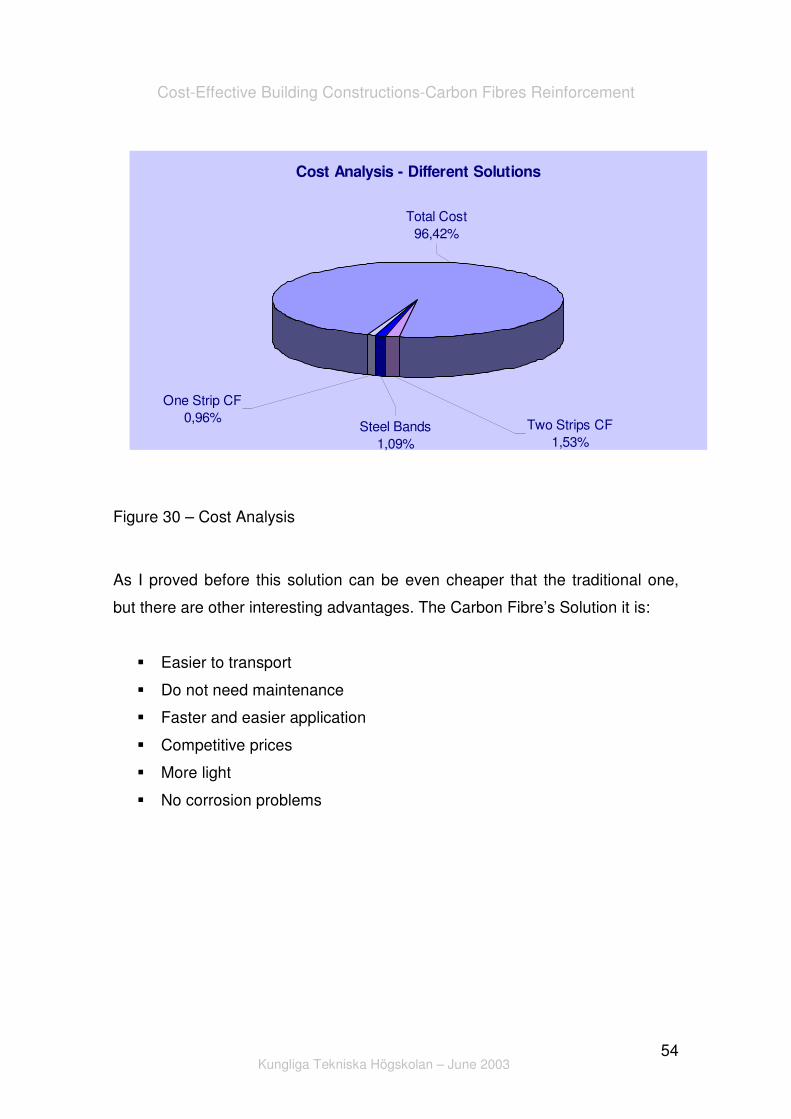
Figure 30 – Cost Analysis
As I proved before this solution can be even cheaper that the traditional one,
but there are other interesting advantages. The Carbon Fibre’s Solution it is:
� Easier to transport
� Do not need maintenance
� Faster and easier application
� Competitive prices
� More light
� No corrosion problems
Cost Analysis - Different Solutions
Two Strips CF1,53%
One Strip CF0,96%
Total Cost96,42%
Steel Bands1,09%

Cost-Effective Building Constructions-Carbon Fibres Reinforcement
Kungliga Tekniska Högskolan – June 2003
55
10. Conclusion
Winning within the construction field means that everyone (engineers,
professors, constructors and students) has to be prepared to improve and find
viable solutions. We must be able to answer to the market demand and come
up with interesting and innovative solutions. However, this market is getting
more demanding as ever before. The costumers claim comfort, functionality,
pleasant spaces and quality of live.
In the other hand, the market is getting bigger… It is our duty, as engineers and
citizens, to present an interesting solution to solve this demanding problem.
Finding a cost-effective and competitive solution is the answer we need. So, in
this point of view a solution that guarantee the same quality and is cost-effective
can be very interesting.
As I showed the solution proposed is economical interesting and has some
other advantages that can be important. If this technology would start to be
implemented in big scale it would became cheaper and cheaper, which could be
one more advantage. Nowadays the constructors are afraid to innovative and to
change their way of working but soon they will realise that this new concept of
reinforcement can be very interesting.

Cost-Effective Building Constructions-Carbon Fibres Reinforcement
Kungliga Tekniska Högskolan – June 2003
56
11. Bibliography
Donnet, Jean-Baptiste, C. M. Peng Jimmy, Rebouilat, Serge, Wang, Tong
Kuan, “Carbon Fibers, Third Edition, Revised and Expanded”, Marcel Dekker,
Inc., New York, 1998;
Ermolenko, I. N., Lyublner, I. P., Gulko, N.V., “Chemically Modified Carbon
Fibers and Their Applications”, VCH, Weinheim, 1990;
Edwards, S.C.,”The Repair of Concrete Structures”, Blackie, Glasgow and
London
“Regulamento de Segurança e Acções para Estruturas de Edifícios e Pontes”,
Lisboa, 1998
http://www.new-technologies.org
http://www.fcc.co.jp
http://www.takenaka.jp
http://www.chicagotribune.com
http://www.enn.com
http://www.dhs.cahwnet.gov
http://www.psrc.usm.edu

Cost-Effective Building Constructions-Carbon Fibres Reinforcement
Kungliga Tekniska Högskolan – June 2003
57
12. Annex

Cost-Effective Building Constructions-Carbon Fibres Reinforcement
Kungliga Tekniska Högskolan – June 2003
58
Sika Technical Data

Cost-Effective Building Constructions-Carbon Fibres Reinforcement
Kungliga Tekniska Högskolan – June 2003
59

Cost-Effective Building Constructions-Carbon Fibres Reinforcement
Kungliga Tekniska Högskolan – June 2003
60

Cost-Effective Building Constructions-Carbon Fibres Reinforcement
Kungliga Tekniska Högskolan – June 2003
61

Cost-Effective Building Constructions-Carbon Fibres Reinforcement
Kungliga Tekniska Högskolan – June 2003
62

Cost-Effective Building Constructions-Carbon Fibres Reinforcement
Kungliga Tekniska Högskolan – June 2003
63

Cost-Effective Building Constructions-Carbon Fibres Reinforcement
Kungliga Tekniska Högskolan – June 2003
64

Cost-Effective Building Constructions-Carbon Fibres Reinforcement
Kungliga Tekniska Högskolan – June 2003
65
Cost-Effective Building Constructions-Carbon Fibres Reinforcement
Kungliga Tekniska Högskolan – June 2003
66

Cost-Effective Building Constructions-Carbon Fibres Reinforcement
Kungliga Tekniska Högskolan – June 2003
67

Cost-Effective Building Constructions-Carbon Fibres Reinforcement
Kungliga Tekniska Högskolan – June 2003
68

Cost-Effective Building Constructions-Carbon Fibres Reinforcement
Kungliga Tekniska Högskolan – June 2003
69

Cost-Effective Building Constructions-Carbon Fibres Reinforcement
Kungliga Tekniska Högskolan – June 2003
70

Cost-Effective Building Constructions-Carbon Fibres Reinforcement
Kungliga Tekniska Högskolan – June 2003
71

Cost-Effective Building Constructions-Carbon Fibres Reinforcement
Kungliga Tekniska Högskolan – June 2003
72
Fire Protection Data
Cost-Effective Building Constructions-Carbon Fibres Reinforcement
Kungliga Tekniska Högskolan – June 2003
73

Cost-Effective Building Constructions-Carbon Fibres Reinforcement
Kungliga Tekniska Högskolan – June 2003
74


![POTENTIAL OF GLASS, BASALT OR CARBON FIBRES FOR ... · fibres are listed in Table 2 and described in detail in the literature [32-38]. Similar to basalt fibres, E-glass fibres (Saint-Go-bain](https://img.dokumen.tips/doc/110x75/5fcc79f2c0fea555e53d9963/potential-of-glass-basalt-or-carbon-fibres-for-fibres-are-listed-in-table-2.jpg)