Embed Size (px)
Citation preview

COST-EFFECTIVE AND RELIABLE DESIGN OF A SOLARTHERMAL POWER PLANT
A. A. Aliabadi* and 1. S. WallaceDepartment of Mechanical Engineering, University of British Columbia*
Department of Mechanical & Industrial Engineering, University of Toronto2054-2324 Main Mall, Vancouver, BC, V6T lZ4, Canada *5 Kings College Road, Toronto, Ontario, M5S 3G8, Canada
Tel: 001-604-827-4273*, Fax: 001-416-978-7753*E-mail: [email protected]*, E-mail: [email protected]
Received January 2009, Accepted March 2009No. 09-CSME-08, E.LC. Accession 3094
ABSTRACTA design study was conducted to evaluate the cost-effectiveness of solar thermal power generation in a 50 kWe
power plant that could be used in a remote location. The system combines a solar collector-thermal storage systemutilizing a heat transfer Huid and a simple Rankine cycle power generator utilizing R123 refrigerant. Evacuatedtube solar collectors heat mineral oil and supply it to a thermal storage tank. A mineral oil to refrigerant heatexchanger generates superheated refrigerant vapor, which drives a radial turbogenerator. Supplemental natural gasfiring maintains a constant thermal storage temperature irregardless of solar conditions enabling the system toproduce a constant 50 kWe output. A simulation was carried out to predict the performance of the system in the hottestsummer day and the coldest winter day for southern California solar conditions. A rigorous economic analysis wasconducted. The system offers advantages over advanced solar thermal power plants by implementing simple fixedevacuated tube collectors, which are less prone to damage in harsh desert environment. Also, backed up by fossil fuelpower generation, it is possible to obtain continued operation even during low insolation sky conditions and at night, afeature that stand-alone PV systems do not offer.
UNE CONCEPTION RENTABLE ET FIABLE D'UNECENTRALE THERMIQUE SOLAIRE
RESUMENous avons entrepris une etude pour evaluer la rentabilite d'un generateur d'energie thermique solaire dans une
centrale de 50 kWe, qui pourrait etre utilisee en des lieux isoles. Le systeme est une combinaison d'un systeme destockage par collecteur solaire thermique utilisant un fluide caloporteur et un simple generateur d' energie de cycleRankine utilisant un refrigerant R123. Les collecteurs solaires atubes sous vide chauffent I'huile minerale et la meten reserve dans Ie reservoir de stockage thermique. Un echangeur de chaleur a !'huile minerale comme refrigerantgenere une vapeur surchauffee frigorigene, laquelle entrai'ne un radiateur turbo-generateur. Un chauffagesupplementaire au gaz naturel maintient une temperature de stockage thermique constante, quelque soit lesconditions de rayonnement solaire, permettant ainsi au systeme d'atteindre une production constante de 50 kWe.Une simulation a permis de prevoir la performance du systeme par une tres chaude journee d'ete, et par une journeetres fro ide d'hiver dans les conditions de rayonnement solaire du sud de la Californie. Une analyse economiquerigoureuse a ete menee. Le systeme offre des avantages sur la centrale thermique solaire de technologie avancee enimplantant de simples collecteurs solaires a tube sous vide fixes, lesquels subissent moins de dommages relies aI'environnement aride du desert. De plus, appuye par un systeme de centrale thermique acombustible fossile, il estpossible d'atteindre une operation en continu, meme en periode de faible ensoleillement et la nuit, unecaracteristique que les systemes autonomes PV/thermiques ne peuvent offrir.
Trans. Can. Soc. Meeh. Eng. Vol. 33, No.1, 2009 25

1. IntroductionSolar thermal power plants have been in commercial operation since 1985 in the Mojave Desert region of
California and with little fanfare have proven to be reliable and cost effective. Nine plants, named SEGS I to IX, havebeen built with total power output capacity of 350 MWe. These Rankine cycle plants have the capability of continuingoperation during non-daylight hours fueled by natural gas.
Smaller power units - kWe rather than MWe sizes - are needed for remote power. Photovoltaic devices aretypically considered for this type of application, but solar dishes with Stirling engines are also being developed. Thesuccess of the SEGS-type system warrants a closer look for lower power applications as well.
The study reported here explores the feasibility of designing a simple 50 kWe solar thermal power unit for remotepower. Use of fixed, non-focusing solar collectors together with a basic Rankine cycle result in lower initial cost butreduced efficiency. The study explores the trade-off between initial cost and performance. Southern California ischosen for the study as representative of a high solar insolation site.
2. The Power Plant CycleThe solar thermal system, figure 1, consists of a collector-storage loop (low temperature storage tank to solar
collector to high temperature storage tank to boiler and back to the low temperature storage tank) and a simple Rankinecycle loop (boiler to turbine-generator to condenser to feed pump and back to the boiler).
Solar 'fherillalPower PlantC:yclc
R,mkillCCydc Pump
CoolingTower
Fig. 1. Solar thermal power plant cycle
In the collector-storage loop, a heat transfer fluid is pumped through the solar collectors, heated to a hightemperature, and then stored in an insulated high temperature storage tank, which is also equipped with an auxiliarynatural gas burner for temperature control of the tank. The auxiliary gas burner makes up the difference between thecollected solar energy and the heat input needed for the refrigerant loop Rankine cycle to produce 50 kWe. Heattransfer fluid discharged from the boiler is collected in the low temperature storage tank to be pumped through the solarcollector again. Refrigerant in the Rankine cycle is evaporated in the boiler, expanded through the turbine, condensed,and then pumped back to the boiler.2.1. Working fluid selection - The Rankine cycle working fluid selection criteria are flammability, toxicity, OzoneDepletion Potential (ODP), Global Warming Potential (GWP), consideration of cycle temperatures and pressures, andthe 1sl and 2nd law efficiencies. R123 is chosen over all other candidates considered because it is a goodthermodynamic match to the operating cycle temperatures, poses no t1ammability or toxicity hazard, and has acceptableODP and GWP potentials.
Mineral oil is selected for effective heat transfer of solar radiation from the collector to the cycle boiler. This oil iswell below its boiling point at the designed 160°C solar collector output temperature, which allows the collector tooperate at atmospheric pressure. This simplifies collector design and enhances safety.
2.2. System Components - Table 1 presents the three major categories of solar collectors that are widely used. Note theestimated temperature ranges and combined collector and Rankine cycle efficiencies [1].
Table 1. Solar collector types
Temperature Range ["C] Collector Type Rankine Cycle Efficiency [%]
90-120 Flat Plate
Trans, Can. Soc. Mech. Eng.
150-200
>315
Evacuated Tube
Tracking Concentrator
Vol. 33, No.1, 2009
10
>11
26

As a compromise between efficiency and overall costs for this low power system, an evacuated tube collector, ableto raise the temperature of the circulating heat transfer media up to 150-200 °e, is chosen. In this type of collector,figure 2, the absorber is inside an evacuated glass tube to reduce convective heat losses compared to flat platecollectors.
Evacuated Tube Solar Collector
Selective AbsorberAbsorber
Vacuum
Radiation Shield
Hear Trans1er Fluid
Fig. 2. Solar collector schematic
The present design concept employs rows of evacuated tube collectors, permanently fixed at the latitude angleand oriented to the south just as is done for flat plate collectors. Figure 3 shows an artist's conception of thisarrangement, minus the connecting piping.
Fig. 3. Solar collector arrangement
A simple unitary boiler design is a key to cost effectiveness of the system. While no suitable small boiler iscommercially available, we propose adapting a vapor generator design shown in figure 4 originally developed byBabcock and Wilcox for nuclear power plants [2]. The heat transfer fluid from the high temperature storage tank passesthrough the tubes of the shell and tube heat exchanger. The refrigerant to be evaporated enters the shell side and isconfined to the lower section of the shell by internal baffles. The refrigerant vapor is superheated by passing along theshell side of the upper part of the tubes, where the incoming oil is hottest.
This boiler is the only custom component of the power plant, but it employs conventional heat exchangertechnology so no fabrication difficulty is anticipated.
Oil Inlet Nozzle
Tube SheeL'i
Supcrllc3tedRefrigerantDUlle' Nozzle
Refrigc:ramInlet Nozzle
Shroud --+AnnualrHcntiugChamber
Sbell
Oil Ouller NOlAe
Fig. 4. Boiler schematic [2]
Trans. Can. Soc. Mech. Eng. Vol. 33, No.1, 2009 27

Radial turbines are recommended for low power and low head applications and also for refrigerant Rankine cycles[3]. Due to the finite number of turbines available on the market, a specific turbine in the desired power range ischosen, and then all other system components are selected to match. A Barber Nichol 50 kWe turbogenerator for R123duty is chosen. The unit combines a radial turbine and an integral 3 phase-60 Hz induction generator. With 1,300 kPaand 140°C turbine inlet conditions, the turbogenerator fluid to electricity efficiency is about 71.5 % [4].
Dry and evaporative condensers are each considered but the high parasitic fan power requirement for dry coolingeliminates that possibility. Evaporative condensers need much less power and are far more compact but do requiresome make-up water. Evaporative cooling can provide hot water for effective waste heat recovery. Waste heatrecovery potentially improves the economics of the system but is not taken into account in this study. A BaltimoreAircoil model CXV-ll9 designed for use with refrigerants was selected.
Most solar thermal systems, e.g. the SEGS plants in California and the Plataforma Solar de Almeria in Spain,incorporate thermal storage of energy. Thermal storage " ... provides an output management tool to prolong operationafter sunset, to shift energy sales from low revenue off-peak hours to high revenue peak demand hours, and tocontribute to guaranteed output" [5]. Also, it provides buffer capacity to level changes in solar insolation [5]. Thepresent design is based on a dual storage tank system in which the hot liquid is stored in a high temperature tank, andthe cold liquid is stored in a low temperature tank. The high temperature tank incorporates a supplemental natural gasftred heater. The tanks were sized to enable the solar plant to be able to operate 24 hours per day during the summer.Cloud cover requires some supplemental natural gas burning and more is required during the winter when there arefewer hours of insolation. The simulation results will illustrate this point.
3. Solar Thermal Power Plant OperationIn order to produce a constant nominal 50 kWe power output, the Rankine cycle system is designed to run in steady
state condition 24 hours a day. By means of the variable heat transfer fluid mass flow rate and the thermal storage, thesystem buffers the heat input to the Rankine cycle so that constant heat input is provided for steady state operation ofthe turbo-generator set.
There are three system control parameters: the mass flow rate of heat transfer fluid through the solar collector, thetemperature in the hot tank (which in turn controls the auxiliary natural gas burner), and the exit liquid refrigeranttemperature (which in turn controls the variable speed cooling fan in the condenser).
4. Technical AnalysisThermodynamic analysis was performed to find the Rankine cycle efficiencies possible for this design. R123 has a
boiling point of 27.9 °c at I atm, which makes it ideal for low pressure Rankine cycles. Engineering Equation Solver(EES) is used to model a simple ideal Rankine cycle. As seen in figure 5, efficiencies competitive with PV solar cellsare attainable using RI23 as the working fluid. The condenser temperature and pressure are considered to be 40°C and200 kPa respectively. The high temperature of the Rankine cycle is considered to be 140°C. Note that the pressure wasvaried ti'om 400 kPa to 1,300 kPa. Since both 1st law and 2nd law efficiencies increase with pressure, it is desired to runthe Rankine cycle at the highest pressure possible (i.e. the maximum turbine inlet pressure). With an inlet pressure of1,300 kPa, a theoretical 1st law efficiency of 17 % and a theoretical 2nd law efficiency of 70 % are possible. However,due to various losses and turbine-generator inefficiencies mentioned earlier, an overall efficiency of 10 % from boilerheat input to electric power is assumed for the simulation analysis.
~ 1st Law Eflidcncy - 21l.1 Law EHi:cocy......- Camot Ellicicl'K:Y
RO -,---------------,
....... 70
~ 60
~ 50OJ~ 40
q30
! 20
10
o -I--~___,-___,_-__,_-~-~----Io 2lKl 41KI (,tKl XlKl IlKKI 121K) 14lKi
Turhire Incl Pressure IkPaI
Fig. 5. R123 ideal Rankine cycle efficiency, 2nd law efficiency, and corresponding Carnot cycle efficiency
Trans. Can. Soc. Mech. Eng. Vol. 33, No.1, 2009 28
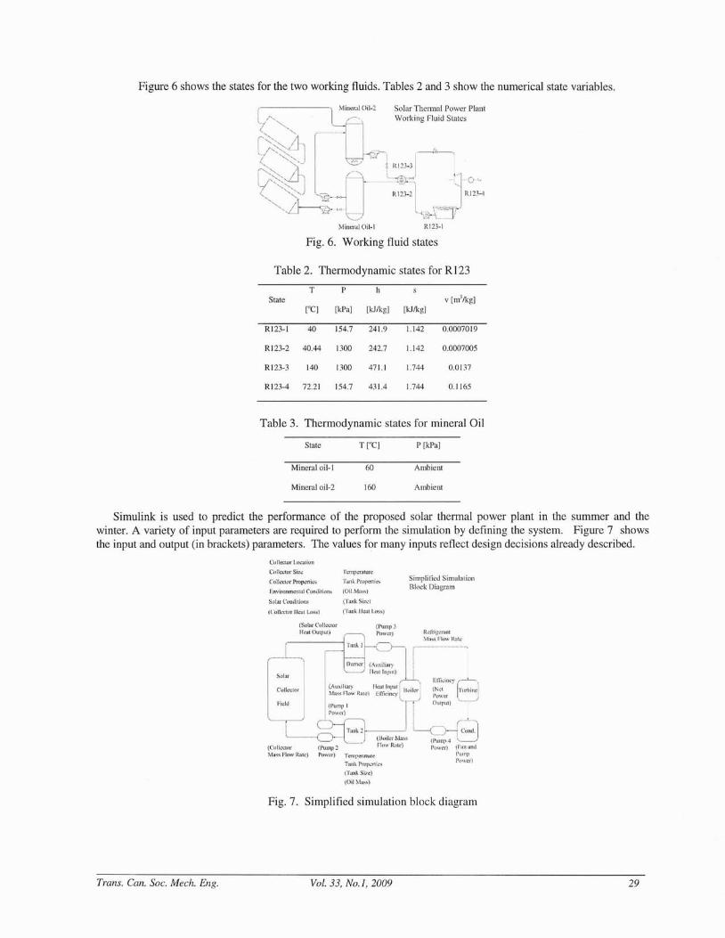
Figure 6 shows the states for the two working fluids. Tables 2 and 3 show the numerical state variables.
1 Mineral Oil-2 Solar Thermal Power PlantWorking Fluid Slales
R123-1
Fig. 6. Working fluid states
Table 2. Thermodynamic states for R123
T PState v [m'/kg]
["C] [kPa] [kJ/kg] [kJ/kg]
R123-1 40 154.7 241.9 1.142 00007019
R123-2 40.44 1300 242.7 1.142 0.0007005
R123-3 140 1300 471.1 1.744 0.0137
R123-4 72.21 154.7 431.4 1.744 0.1165
Table 3. Thermodynamic states for mineral Oil
State
Mineral oil-I
Mineral oil-2
T ["C]
60
160
P [kPa]
Ambient
Ambient
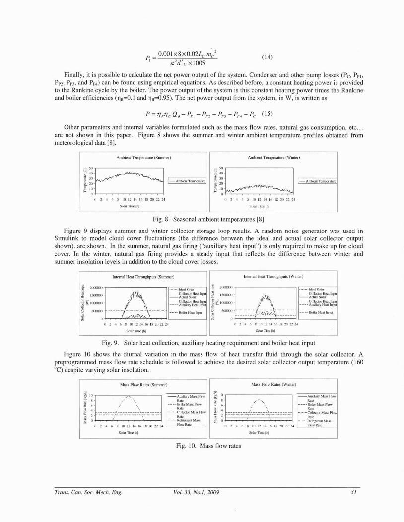
Simulink is used to predict the peliormance of the proposed solar thermal power plant in the summer and thewinter. A variety of input parameters are required to perform the simulation by defining the system. Figure 7 showsthe input and output (in brackets) parameters. The values for many inputs reflect design decisions already described.
C{llleClor Location
CI.\llcctorSizc l"L.i11pL.'TiltU,n:
ColkclOT Propcrlic:, T~Il.k 1>tl)peni~~
Environmental Conditions (Oi] Mils51
Sol,l! l'ollditi(llls (T;'L~lk Sit... )
(ColJCl.:lOr H;;:al Loss) (Tank Ileal Los.»
(rank Si2t:)
(OilMil.s~)
Simplified Simlllal'iOIlBlnck Diagmm
Eflil,.,jncy .....---l....-..,
(Net lrmi)ine iPo\\'~r iOUlflut) •............/
Trans. Can. Soc. Mech. Eng.
Fig. 7. Simplified simulation block diagram
Vol. 33, No.1, 2009 29

The methodology is to predict the performance in the extreme conditions in terms of the solar insolationavailability. Simulations are performed for the nth day of the year, where n=1 corresponds to January 1st. In the analysisn=200 and n=15 are used, and they represent the highest and lowest solar insolation during the year respectively. TheLatitude, L, for southern California is 32.5 degrees. As described earlier, the tilt angle, ~, is chosen to be 32.5 degreesas well. The equations used for the model are based on the methodology of Goswarni, Kreith, and Kreider [6],summarized as follows. The solar declination angle, 8" in degrees, can be written as
0, = 23.45 sin [360 (284 + n)/365] (I)
Using this parameter, the solar hour angle, hs, the solar altitude angle, a, the solar azimuth angle, as, and theincident angle, i, can be all calculated, in degrees, as
h = Minutes from solar noon /4 (2),a = sin -I [sin Lsin 0, + cos Lcos 0, cosh J (3)
a, = sin -I [cos 0, sinh J cos a] (4)
i = COS-I [cosacos(a, -a)sin,8+sinacos,8] (5)
Various sky optical properties were considered. The sky clearness, Cn, is assumed to be 1 for all practicalpurposes. Sky diffusive factor, C, varies from day to day, and is assumed to be 0.]4 for n=200 and 0.06 for n=15.The sky optical depth, k, is assumed to be 0.21 for n=200 and 0.14 for n=15 [6].
To determine the solar insolation incident on the collector, Ie, various calculations must be performed. Solarirradiation reaching the earth's surface, Ibn, can be calculated using the solar constant, la, and the solar irradiation ontop of the atmosphere, I, for any given n. These parameters can be calculated, in W/m2 as
1= 10 x (1 + 0.034 cos( 365 nl365 .65) (6)
11m
= C,Je-klsina (7)
Next, the horizontal, direct, diffuse, and reflective components of the solar irradiation, Ih, Ibe, Ide, Ire, respectively,need to be calculated. The incident angle, the tilt angle, and the desert ground reflectivity, p=0.2, are required forthese calculations. Finally, the solar insolation reaching the collector, Ie, is the sum of the three direct, diffuse, andreflective components. In W/m2
, the equations can be shown as
Iii = CJle-klsina J[C +sin a] (8)
l he = I h ." cos i (9)
Ide = Clh,,,(l + COS ,8)/2 (10)
Ire = pl" (1 - cos ,8) 12 (11)
Ie = Ihe + I de + / re (] 2)
The heat input to the collector is expressed using various parameters outlined before. In addition, the collectorconstant, (aT)=0.85, collector area, Ae=2000 m2
, average collector heat transfer coefficient, U=0.9 W/m2K, collectorpipe diameter, de=O.1 m, collector accumulated length, Le, average absorber temperature, Tabs=] 10 DC, collector andglass temperature difference, t.Te, ambient temperature, Tamb, and overall collector emittance, £=0.09 are used. Afirst law energy balance would give the heat input to the collector, in W, as
Qc = (ar)/cAc -UJrdcLc(TAh, -t.Tc -TAmb ) (13)
-£C5Ac ((TAb., + 273)4 - (TAmb + 273)4)
The most significant parasitic loss in the system is associated with pumping the mineral oil through the solarcollector. The oil is highly viscous and turbulent (Re:::::3000). For this flow, the Weisbach formulation applies, andgives a good estimate for the pressure differential needed across the collector to drive the flow [7]. Using themineral oil mass flow rate, collector length and diameter, an approximate pipe friction factor can be read from theMoody chart. The pressure drop, in kPa, can be calculated as
Trans, Can. Soc. Mech. Eng. Vol. 33, No.1, 2009 30
0.001x8xO.02Lc 111/JC
2d 5C x 1005
(14)
Finally, it is possible to calculate the net power output of the system. Condenser and other pump losses (Pc, PPI,PP2, PP3, and PP4) can be found using empirical equations. As described before, a constant heating power is providedto the Rankine cycle by the boiler. The power output of the system is this constant heating power times the Rankineand boiler efficiencies (11R=O.l and 118=0.95). The net power output from the system, in W, is written as
Other parameters and internal variables formulated such as the mass flow rates, natural gas consumption, etc ...are not shown in this paper. Figure 8 shows the summer and winter ambient temperature profiles obtained frommeteorological data [8].
Ambient Temperature (Summer)
~"'E:S~ 40
{::_ I-,,·m-,_..,~ 10
0-
() 2 4 (1 x 10 12 14 10 IR 20 22 24
Ambient Tempemture (Winter)_50c:;:]~ 4n.2 30~ 21) 1- AlI~licnl Te[l~)cf:llllrcl
~ 10
oo 2 4 () X [0 12 [4 [6 IX 20 22 24
Solar TItre Ihl Slll:lr"nncjllj
Fig. 8. Seasonal ambient temperatures [8]
Figure 9 displays summer and winter collector storage loop results. A random noise generator was used inSimulink to model cloud cover fluctuations (the difference between the ideal and actual solar collector outputshown). are shown. In the summer, natural gas firing ("auxiliary heat input") is only required to make up for cloudcover. In the winter, natural gas firing provides a steady input that reflects the difference between winter andsummer insolation levels in addition to the cloud cover losses.
Intemal Heat Tlu'ollghpllts (Summer) Intcmal Heat Throughputs (Winter)
4 fi R III 12 14 16 IR 2022 24 o 2 4 6 X In 12 [4 J(l IX 20 22 24
----- BoiEr He:llinput
0- 2(XXXXJO ,------------, ------,I<lc:li So,,,'
Collector Hcallnpu- Actual Solar
Col!cCllll' Hcallnpu- - - - Auxiliary Heallnpul
;;x 1500000
j ~ ]000000
8 500(}OO
a
,g. 2000000,-------------, r--,:-:I<I-C":-:IS,--o',--.\I.------j
X 15000()O' B···· _~~:~ts~l~~at Inpu
_8~ 1000000 Collcclor Heat Inpu~ ---- Auxiliary Heal Input'0 '
~ 5Im:: +--.,---,--c--...,.--L..'+'-':>:'-~,..i-~!'-l:~'-.L~{~-\l~~>L:;"...J.,-----""'---'''''----1 L--_--_-_S,_lilc_'_Hc_a_ll_'1P_Ul---1
oSuL:lf 'fUle I.hl Solar Time Ih]
Fig. 9. Solar heat collection, auxiliary heating requirement and boiler heat input
Figure IO shows the diurnal variation in the mass flow of heat transfer fluid through the solar collector. Apreprogrammed mass flow rate schedule is followed to achieve the desired solar collector output temperature (1600c) despite varying solar insolation.
Mass Flow Rates (S ummer) Mass Flow Rates (Winter)
~ Ili
l.- l-AUXil"ryM:L<SFIIW
~ H R~c~ (]' ---- BlIiler Mass Flow
g 4 -' ~________ ~~~II~ttlllrMass FklW
~ 2(J - - -. ,-- -- ---- ---'----- ----- R:L1c:::E - - -----Rcli"igcrantMass
() 2 4 (1 X 10 12 14 16 IX 20 22 24 '---_F'-"I,'-"w'-'R:.::;;II.:..C__.11
~ [Ol l-AlIxmaryMaSSFilW
~ :mm,m,nn,n,uE!'M_'''.~ 2 ~. - - -. _. - - - - - - - -::: -···-··~:lltl:L:lor Mass Fkl\\
~ II - . -. Rclrigcranl Mass
() 2 4 6 X III [2 14 16 IX 20 22 24 '----'-F:.::;low:.::;R:.::;:l:.::;IC__.11
Solar Tin'C [h] Sul:lrTilllc Ill]
Fig. 10. Mass flow rates
Trans. Can. Soc. Mech. Eng. Vol. 33, No.1, 2009 31
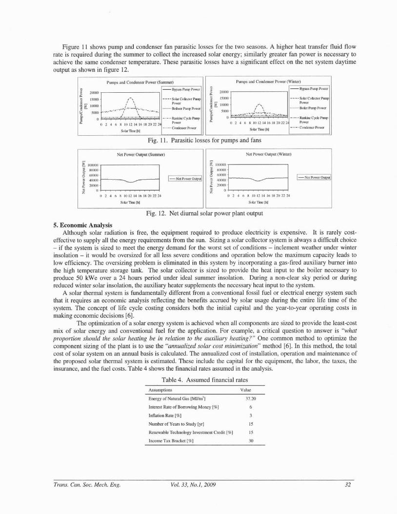
Figure 11 shows pump and condenser fan parasitic losses for the two seasons. A higher heat transfer fluid flowrate is required during the summer to collect the increased solar energy; similarly greater fan power is necessary toachieve the same condenser temperature. These parasitic losses have a significant effect on the net system daytimeoutput as shown in figure 12.
Sobr TIne Ihl
Pumps and Condenser Power (Summer),..--------,
-_ .• Rankil'C Cycle PUllflPower
----. Condett'icrPowcr
- - - - Solar Colkx(or PumpPower
. . .... Bnile.. PUll'll Power
$lllarlinc jill
Pumps and Condenser Power (W,...-in_te~r) _
~ - Bypass Pump Powerf1. 21XllXl,---------...,
~ ISOtX)
~ ?i 100m .... ,0- f \
~ 5000 ..._...........:.-:~-:._~~ ..:.::::7.::..::.:~: ...... -.-.,:; 00. 0 2 4 6 X 10 12 14 16 IX 20222
_._ •• Rankine Cyd~ Pump
Power
_ .. _. Condenser Power
- - - - Solar Collcl,;lor PumpPower
....... Boilwcr Pump Power
,-,I ,
I ,
..".,.-.-." .~- ~/ '\......_~~ ...._...... ,~. '''',
I ,._. _. L. _. .~. _. _ ._. _._
oo 2 4 (, X 10 12 14 16 IX 20222
! 2(}()()() ,- ---, -- Bypass PUll"" Power
~ _ 151XXI
~ ~ WOODS-~ SOoo
£
Fig. 11. Parasitic losses for pumps and fans
Net Power Output (Summer) Net Power Output (Winter)
X III 12 14 16 IX 211 22 24 X 10 12 14 16 IX 211 22 24
~ \(KKXXII I5. xO<X)O
8 (lO(X)()
~ 41XKXl r---:::f1. 21XXXI . . .~ oh~~~~~~~~
() 2 4 6
1-Net Power Output!
~. 100KXKli Is. X1XXXl<3 (10000-
ti 40000 _r----:::~ 20000
~ () h~~~~~~~~-o 2 4 6
1-Net Power Output!
Sobr lim::: Ilil
Fig. 12. Net diurnal solar power plant output
5. Economic AnalysisAlthough solar radiation is free, the equipment required to produce electricity is expensive. It is rarely cost
effective to supply all the energy requirements from the sun. Sizing a solar collector system is always a difficult choice- if the system is sized to meet the energy demand for the worst set of conditions - inclement weather under winterinsolation - it would be oversized for all less severe conditions and operation below the maximum capacity leads tolow efficiency. The oversizing problem is eliminated in this system by incorporating a gas-fired auxiliary burner intothe high temperature storage tank. The solar collector is sized to provide the heat input to the boiler necessary toproduce 50 kWe over a 24 hours period under ideal summer insolation. During a non-clear sky period or duringreduced winter solar insolation, the auxiliary heater supplements the necessary heat input to the system.
A solar thermal system is fundamentally different from a conventional fossil fuel or electrical energy system suchthat it requires an economic analysis reflecting the benefits accrued by solar usage during the entire life time of thesystem. The concept of life cycle costing considers both the initial capital and the year-to-year operating costs inmaking economic decisions [6].
The optimization of a solar energy system is achieved when all components are sized to provide the least-costmix of solar energy and conventional fuel for the application. For example, a critical question to answer is "whatproportion should the solar heating be in relation to the auxiliary heating?" One common method to optimize thecomponent sizing of the plant is to use the "annualized solar cost minimization" method [6]. In this method, the totalcost of solar system on an annual basis is calculated. The annualized cost of installation, operation and maintenance ofthe proposed solar thermal system is estimated. These include the capital for the equipment, the labor, the taxes, theinsurance, and the fuel costs. Table 4 shows the financial rates assumed in the analysis.
Table 4. Assumed financial rates
Assumptions Value
6
37.20Energy of Natural Gas [MJ/m'J
Interest Rate of Borrowing Money [%]
Inflation Rate [%]
Number of Years to Study [yrJ IS
Renewable Technology Investment Credit [%] IS
Income Tax Bracket [%] 30
Trans. Can. Soc. Mech. Eng. Vol. 33, No.1, 2009 32

Price of Natural Gas for Electric Power Generation
202120162011
0.7 -r--------------------,"i:'9 0.6~ 0.5
13 0.4
~ 0.3e0.2
6: 0.10-1------,-----,.---------12006
Year
Fig. 13. Projected US natural gas price [9]
Table 5 summarizes the estimated costs for the system construction and operation. The largest initial cost isassociated with the solar collector; yet, the largest operating cost is associated with the natural gas consumption. Thecost of evacuated tube collector has been estimated to be $300 1m2 [10]. Natural gas prices used in the cost analysisare shown in figure 13. These prices account for the historical increase over the last 15 years [9].Due to theimportance of these costly items a sensitivity analysis was conducted in which the cost of the solar collector and naturalgas was varied by ±15 %. The annualized system cost varied by ±l % for the solar collector and ±5% for the naturalgas. Thus, the strongest dependence is associated with the future natural gas prices.
Figure 14 shows that the annualized cost falls as collector area increases up to 2000 m2, an area that provides full
system heat requirements under ideal summer sky conditions. The remaining input energy required to produce 50 kWeis provided by the natural gas fired auxiliary heater. Above 2000 m2
, additional collector costs, and increased thermalstorage capacity, more than offset fuel savings. The fuel efficiency of the system is more than 45 % on an annualaverage basis, due to the solar contribution, whereas the typical efficiency of a simple Rankine cycle power plant isabout 25 %. This means that this solar thermal power plant, in the right comparison, reduces greenhouse emissions by afactor of almost two.
Table 5. Estimated costs
Costs
Solar Collector
Collector Support Structure
Thermal Storage Tank
Synthetic Oil
Auxiliary Heater
Pumps
Condenser
Turbine Generator
Pipes and Valves
Boiler Heat exchanger
Controls
Wiring
Labor
Total (Present Worth)
Maintenance [/yr]
Operation Labor [/yr]
Insurance [lyr]
Total Fuel Cost (Present Worth)
End of Life Value of the Plant (Future Worth)
$600,000
$20,000
$10,000
$42,000
$1,000
$21,500
$15,000
$35,000
$15,800
$17,500
$9,500
$5,400
$120,000
$912,700
$3,000
$33,000
$1,500
$613,332
($40,000)
Annualized Cost $139,554
Trans. Can. Soc. Mech. Eng. Vol. 33, No.1, 2009 33

Annualized Cost vs. Solar CoUector Area
1000 1500 2000 2500500
$300,000 -,----------------,
$250,000
$200,000
$150,000
$100,000
$50,000
$0 -I-----.,...---,------.,...---.-----.,-J
°Solar Collcculr Arc.l ISquare Meter)
Fig. 14. Annualized system cost ($US)
6. Discussion
Despite the advantages, it goes without saying that the proposed solar thermal power plant poses specialrequirements on its installation site. As illustrated by Fig. 15 in the appendix, the power plant requires I hectare ofdesert land, primarily covered with solar collectors that preclude use of the land for other purposes (but that is not aproblem for the usually unutilized desert land). An additional resource requirement is created by the evaporativecondenser that consumes water. An evaporative rather than a dry condenser is necessary to achieve a heat rejectiontemperature not too much above ambient. Due to the low heat input temperature of the solar thermal plant thecondenser temperature has a large impact on system efficiency. If the waste heat could be utilized - not considered inthis analysis - the overall efficiency and therefore the economics of the project would be much improved.
Considering the amortization of the system for 15 years and assuming 350 days of full-time operation per year, thepower plant is capable of providing electricity at $0.33 per kWh. For comparison, as Quaschning explains, the currentsolar thermal electricity prices are estimated to be €0.15 ($0.21) per kWh [11]. The cost of the larger system benefitsfrom economy of scale and is a realistic number based on actual installations. However, the cost estimates in this paperare conservative projections for the installed cost of a unique prototype system. On the other hand, as opposed totracking and focusing collectors, the fixed evacuated tube collectors operate more reliably, do not need frequentmaintenance, and are less prone to damage in harsh desert environment.
A further comparison can be made with stand-alone photovoltaic systems. According to Van del' Vleuten, PVsystem developments still mainly rely on government subsidies in the form of tariffs and only benefit from economicreturns if considered for large scale (MW) installations [12]. This, often, results in high financial risks to be taken bygovernments and venture capitalists. In 2007, the IEA PVPS Task 8 report was presented in Athens, Greece, organizedby European Photovoltaic Industry Association (EPIA). As calculated in this report in 2006, Beneking explains thatstand-alone PV power costs €0.24-€0.38 ($0.33-$0.53) per kWh [12]. On the other hand many solar thermal powerplants, including SEGS, are privately commercialized and generate power more economically. Also, stand-alone PVsystems do not have the same functionality as the proposed solar thermal system, which produces power 24 hours aday.
In order to make a comparison with a PV system having the same functionality as the proposed solar thermal powersystem, it would be necessary to consider a hybrid PV system with battery storage and possibly a backup generator. APV-diesel generator hybrid unit is under construction for a mountain hut in the Lambardia Alps. This system isrequired to produce a maximum of 28.8 kWh per day. The system has been optimized and economic calculations areperformed for a 25 year amortization period. Under best scenarios, the cost of producing electricity for this system isprojected as €0.31 ($0.43) per kWh [13]. The electricity cost produced by this hybrid PV system is higher than that ofthe proposed solar thermal power system. This is mainly because such hybrid systems need expensive battery storagein addition to the costly generators and PV panels.
7. Conclusions
The goal of this study was to propose a cost-effective and reliable solar thermal power plant. The power plant wasdesigned for a small scale application which produces 50 kWe in the sunny climate of southern California. The designemphasis was to reduce cost by using simple technologies. The proposed power plant is a combined cycle binary
Trans. Can. Soc. Mech. Eng. Vol. 33, No.1, 2009 34

working fluid system that operates on solar energy and natural gas. The main heat input to the system is from solarthermal energy collected by evacuated tubes. This energy is supplemented by a natural gas fired heater which providesnecessary heat input when the solar energy is not available in abundance. A Rankine cycle converts the heat input tothe system by a turbine generator set. Performance of the proposed system has been simulated and used in theeconomic analysis. Using life cycle costing analysis, the cost of producing electricity from a plant of this design isestimated at $0.33 /kWh.
Compared to advanced solar thermal and photovoltaic power plants, the proposed system offers cost savings andreliability. The proposed plant utilizes evacuated tube collectors that remain efficient even in slightly cloudy skyconditions. These collectors require less maintenance and operate more reliably than tracking concentrators in the harshdesert environment. The proposed system is base loaded by natural gas, so that it can provide power 24 hours a day,regardless of solar insolation availability.
Acknowledgement
The authors gratefully acknowledge the artistic work of Reza Aliabadi who created the magnificent 3D model ofthe proposed solar thermal power plant.
Nomenclature
Ae = collector area
C = sky diffusive factor
C" = sky clearness
I = solar irradiation on top of atmosphere
10 = solar constant
Ihe = direct solar irradiation
h" = solar irradiation reaching the earth
Ie = solar insolation reaching collector
Ide = diffuse solar irradiation
Ih = horizontal solar irradiation
Ire = reflective solar irradiation
L = latitude
Le = collector accumulated length
P = pressure - power output
PI = collector pressure drop
PPi = pump i loss
Pe = condenser loss
QR
= Rankine cycle heat input
Re = Reynolds number
T = temperature
Tahs = average absorber temperature
Tamh = ambient temperature
U = average collector heat transfer coefficient
de = collector pipe diameter
h = enthalpy
hs = solar hour angle
i = incident angle
k = sky optical depth
Trans. Can. Soc. Mech. Eng. Vol. 33, No.1, 2009 35

~c = collector mass flow rate
n=day
s = entropy
D.Tc = collector and glass temperature difference
a = solar altitude angle
as = solar azimuth angle
at = collector constant
~ = collector tilt angle
8, = solar declination angle
c = collector emittance
11B = boiler efficiency
11R = Rankine cycle efficiency
p = ground reflectivity
References
[1] Barber, R. E., Current costs of solar powered organic Rankine cycle engines, Solar Energy, 20 (1) (1978) 1-6.
[2] Fraas, A. P., Heat Exchanger Design, 2nd Ed., John Wiley & Sons, New York, 1989.
[3] Mobarak, A., Rafat, N., and Saad, M., Turbine selection for small capacity solar power generation, Desalination (3)(1980) 13S1-1367.
[4] Radial inflow turbines, Barber Nichols: Design and Manufacture of Specialty Turbo-machinery.
Avai lable from: <http://www.barber-nichols.com/products/turbines/radiaUnflow_turbines/default.asp>[referenced 2007].
[S] Winter, C. 1., Sizmann R. L., and Vant-Hull L. L., Solar power plants, fundamentals technology and systemeconomics, Spring-Verlag, New York, 1991.
[6] Yogi Goswami, D., Kreith F., and Kreider, J. F., Principles of solar engineering, 2nd Ed., Taylor & Francis,Philadelphia, 2000.
[7] White, F. M., Fluid mechanics, Sth Ed., McGraw Hill Higher Education, New York, 2003.
[8] Monthly average temperature for Calexico,
CA, The Weather Channel. Available from:
<http://www.weather.com/weather/wxclimatology/monthly/graph/USCAO IS0?fTom=search> [referenced 2007].
[9] Natural gas, Energy Information Administration, Department of Energy, U.S. Government. Available from:
<http://www.eia.doe.gov/oil_gas/natural~as/info_glance/naturaLgas.html>[referenced 2006].
[10] Silicon Solar Inc. Available from: <http://www.siliconsolar.com/index.php> [referenced 2007].
[11] Quaschning, V., Solar thermal power plants, Renewable Energy World, 6 (6) (2003), 109-113.
[12] Milford E., Approaching the horizon - very large scale photovoltaics, Renewable Energy World, 10 (4) (2007),174-183.
[13] Iannone, F., Leva, S., and Zaninelle, D., IEEE, Hybrid photovoltaic system and sustainability: economic aspects.Available from: <http://ieeexplore.ieee.org/ieIS/94SlI300 10/0137321S .pdf?arnumber=137321S> [referenced 2007].
Trans. Can. Soc. Mech. Eng. Vol. 33, No.1, 2009 36

Appendix
Fig. 15. Solar thermal power plant 3D model
Turbine and Pump Room
Thermal Storage Tanks
DevelopmentPlatforms
Cooling Tower
100m
Solar Collector Field
Control Room
Service Access
Trans. Can. Soc. Mech. Eng. Vol. 33, No.1, 2009 37

Trans. Can. Soc. Mech. Eng. Vol. 33, No.1, 2009 38