Embed Size (px)
Citation preview
by
Corrosion Repairs in C&W
Introductory topics
• Corrosion Prone areas in ICF Coaches & BOXN Wagons
• Factors affecting Corrosion
• Preventive actions
Basic Objectives
• Corrective measure i.e. Corrosion Repairs
– Inspection
– Corrosion diagram in rolling stocks
– Repair procedures
• Cutting by oxygen & combustible gas flames/Electric Arc & air plasma
• Surface/Edge preparation
• Welding/fabrication Coated arc/Bare electrodes
• Finishing/surface grinding
– Corrosion Repair shop management
– Wagon body rehabilitation / BOXNR conversion
Corrosion Repairs in Rolling
Stocks : C&W – Sequences.
• Inspection of carriage & wagon for corrosion diagrams ?
• Whether it is excessive ? Refer RDSO pamphlets !
– If yes for corrective action corrosion repairs in the affected stock
• then gas/plasma arc cut corroded sections & dress the kerfs !
• next renew/refit new properly surface treated sections by arc
welding with edge preparations if reqd. !
• finishing fabrications/welded joints by angular grinding !
– Else
• scrap the rust & repaint !
• again think of preventive action wherever possible !

Galvanic Corrosion cells : ICF coaches -
• Concentration cells
Solebar, Trough floors, Turnunders & body pillars in
vulnerable regions, roof ventilators & water wriggles
• Stress cells
Headstocks & Trough floors in other non vulnerable
regions where there is cold press bending sans any
heat treatment / non stress relieved weldings
• Dissimilar material contact cells
MS Crossbars supporting SS Trough floors & MS
lavatory U channels 2mm thick supporting SS
lavatory inlays
Coaching Corrosion Repair pamphlets
& technical guidelines -
• For ICF BG coach
RDSO pamphlet C 7602 Rev. 01, Dec.1992
• For BEML BG coach
RDSO pamphlet C 75003
• Technical instructions of ICF MG coach
Corrosion repairs : RDSO CMI K-302
• Corrosion repair procedures of Carriage
Headstock assemblies issued by RDSO dtd.
21/12/2010

ICF & BEML coach corrosions :
a very brief history - Before 1977 in ICF & BEML coaches
1. No window sealing in non AC coaches
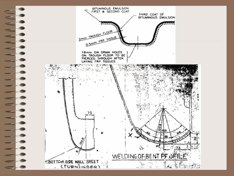
2. 5 mm thick Turn Under with drain holes
3. 1st corrosion repair in coaches is 6 yr.s following
mfg.
After 1977 in ICF & BEML coaches
1. Window sealing in non AC coaches
2. 2 mm thick lower body wall sheet
3. 1st corrosion repairs in ICF & BEML coaches are
9 yr.s & 7 yr.s following mfg.
ICF coach underframe
modifications
• In 1974, solebar stiffening by 6mm/3.15
mm thick boxing was done in ICF BG
coaches from the inner headstock end to
body bolster end following RDSO Sketch
nos. 75080, 76011 + 76012 to prevent the
lavatory region solebars from corrosion
• But the boxings stored electrolytic lavatory
seepage water thereby getting corroded
ICF coach underframe
modifications
• In 1989, MgOCl Decolite flooring in
coaches is replaced by 2mm thick light
waterproof PVC sheets preventing water
soaking & further seepage in underframe
• This saved tare weight & further prevented
corrosion in the modified carriages
ICF coach underframe
modifications
• 19 mm diameter zigzag drain holes are
provided in the 2 mm thick MS trough
floors these trough floors are designed for
absorbing about 70% of buffing loads
• 217 mm X 127 mm edge chamfered
elliptical drain holes are provided in the 5
mm thick turnunders preventing water
accumulation in corrosion vulnerable spots
ICF coach underframe
modifications
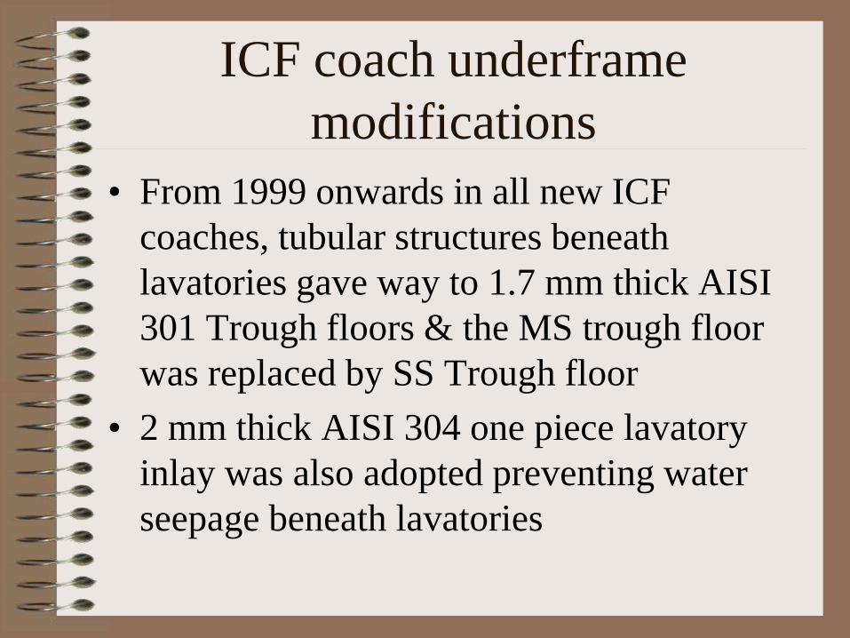
• From 1999 onwards in all new ICF
coaches, tubular structures beneath
lavatories gave way to 1.7 mm thick AISI
301 Trough floors & the MS trough floor
was replaced by SS Trough floor
• 2 mm thick AISI 304 one piece lavatory
inlay was also adopted preventing water
seepage beneath lavatories
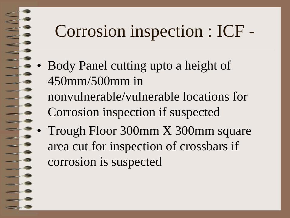
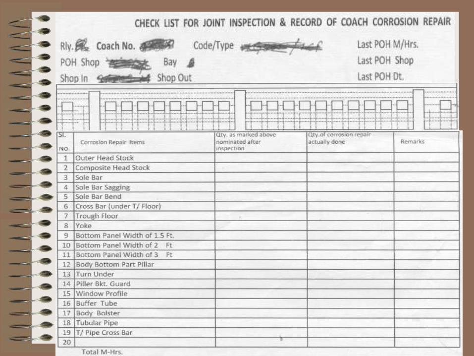
Corrosion inspection : ICF -
• Body Panel cutting upto a height of
450mm/500mm in
nonvulnerable/vulnerable locations for
Corrosion inspection if suspected
• Trough Floor 300mm X 300mm square
area cut for inspection of crossbars if
corrosion is suspected

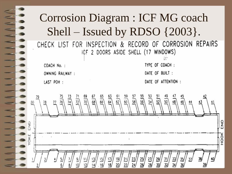
Corrosion Diagram : ICF MG coach
Shell – Issued by RDSO 2003.
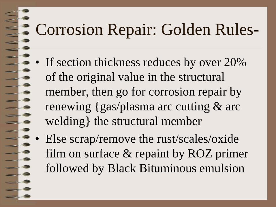
Corrosion Repair: Golden Rules-
• If section thickness reduces by over 20%
of the original value in the structural
member, then go for corrosion repair by
renewing gas/plasma arc cutting & arc
welding the structural member
• Else scrap/remove the rust/scales/oxide
film on surface & repaint by ROZ primer
followed by Black Bituminous emulsion
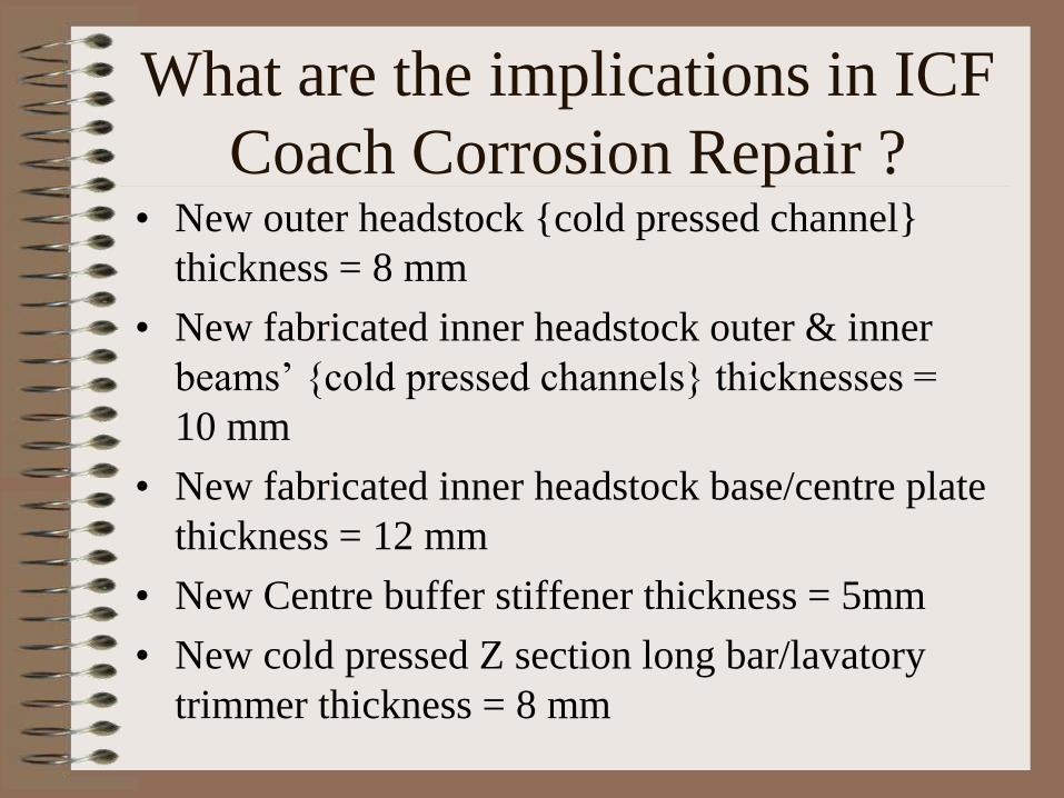
What are the implications in ICF
Coach Corrosion Repair ? • New outer headstock cold pressed channel
thickness = 8 mm
• New fabricated inner headstock outer & inner
beams’ cold pressed channels thicknesses =
10 mm
• New fabricated inner headstock base/centre plate
thickness = 12 mm
• New Centre buffer stiffener thickness = 5mm
• New cold pressed Z section long bar/lavatory
trimmer thickness = 8 mm
What are the implications in ICF
Coach Corrosion Repair ?
• New fabricated boxform body
bolster/centre “casting”/main transom
flange thickness = 16 mm
• New fabricated boxform body
bolster/centre “casting”/main transom web
thickness = 10 mm
• New cold pressed Z section/C channel
solebar/crossbars = 5 mm WLRRM
Solebar new thickness is however 8 mm

What are the implications in ICF
Coach Corrosion Repair ? • If the outer headstock or longbar thickness comes
down to 6.4 mm from the original value 8mm,
then it must be replaced by corrosion repair
• If the inner headstock beam thicknesses fall beneath
8 mm, then it must be replaced by corrosion repair
• If the Centre Buffer Stiffener i.e. Destruction Tube
thickness falls beneath 4 mm, then it must be
replaced by corrosion repair
• If the inner headstock base plate thickness falls
beneath 9.6 mm, then it must be replaced by
corrosion repair • Contd.
What are the implications in ICF
Coach Corrosion Repair ?
• If the body bolster flange thickness falls beneath
12.8 mm and/or its web thickness falls beneath 8
mm then replace the body bolster entirely
• Patchwork/partial renewal of headstocks & body
bolster for ICF coach corrosion repair is not
recommended by RDSO
• Huge corrosion repair manhours/cost &
diminished outturn by repair shops
• Ineffective rolling stocks position in Divisions
turns worse
What to do ? Can such corroded coaches be
despatched from Workshops by local passing?
• The answer is a big NO i.e. Neutral
Control Inspection & Passing cannot be
avoided at all by the Workshops officers
• CME/Zonal Railway is empowered to
issue fresh guidelines/LTOs Local
Technical Orders/TSOs Technical
Standing Orders for Repair Shops from
Passenger Safety viewpoint similar to RCF
issuing the STRs Schedule of Technical
Recommendations in LHB coaches
ER LTO & TSO : ICF -
• If the outer headstock thickness falls to
4mm from 8mm, then it should be renewed
• Similarly if the inner headstock beam/base
plate thickness falls to 6mm/8mm from
10mm/12mm, then it should be renewed
• From 16mm/10mm down to
11mm/6.85mm body bolster flange/web
thicknesses, a 5mm/3.15mm thick IRSM41
patch can be suitably plug welded
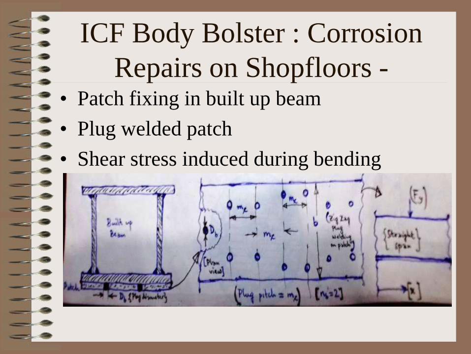
ICF Body Bolster : Corrosion
Repairs on Shopfloors - • Patch fixing in built up beam
• Plug welded patch
• Shear stress induced during bending

Straight Beams: Bending Shears-
• Governing equations
[ ] ( ) 0x
x y
[ ] ( ) 0y
x y
y z
y
F Mw F
x x
0cAy ydA x
yd y
d
x xE
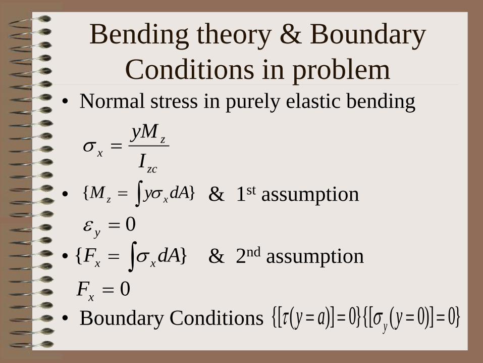
Bending theory & Boundary
Conditions in problem • Normal stress in purely elastic bending
• & 1st assumption
• & 2nd assumption
• Boundary Conditions
z
x
zc
yM
I
0y
0xF
z xM y dA
x xF dA
[ ( )] 0[ ( 0)] 0yy a y

Stress Calculations in bending
• Straight built up beams
2 2
2
y
zc
a yF
I
3 6
y
zc
wy
I
2 2 2[( ) ]2
x y
m xy
xy yx
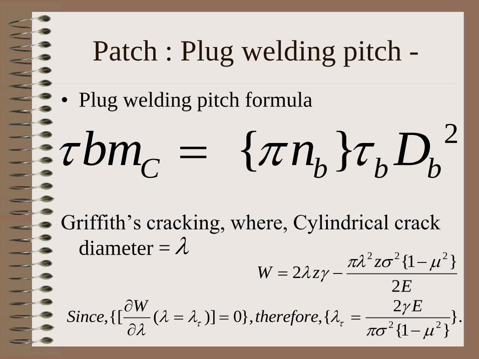
Patch : Plug welding pitch -
• Plug welding pitch formula
Griffith’s cracking, where, Cylindrical crack
diameter =
2 C b b bbm n D
2 2 21 2
2
zW z
E
2 2
2,[ ( )] 0, , .
1
W ESince therefore

Curved Beams: Bending Shears-
• Governing Equations
[ ( )] 0r
r
[ ( )] 0rrr
cAR rdA
n
A dA
R r
r z
r
c c
F Mw F
R R
nr R d
rd
E
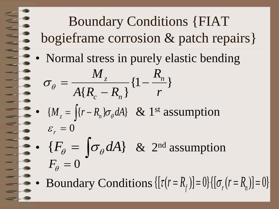
Boundary Conditions FIAT
bogieframe corrosion & patch repairs
• Normal stress in purely elastic bending
• & 1st assumption
• & 2nd assumption
• Boundary Conditions
0r
0F
1
nz
c n
RM
A R R r
[ ( )] 0[ ( )] 0f r nr R r R
z nM r R dA
F dA
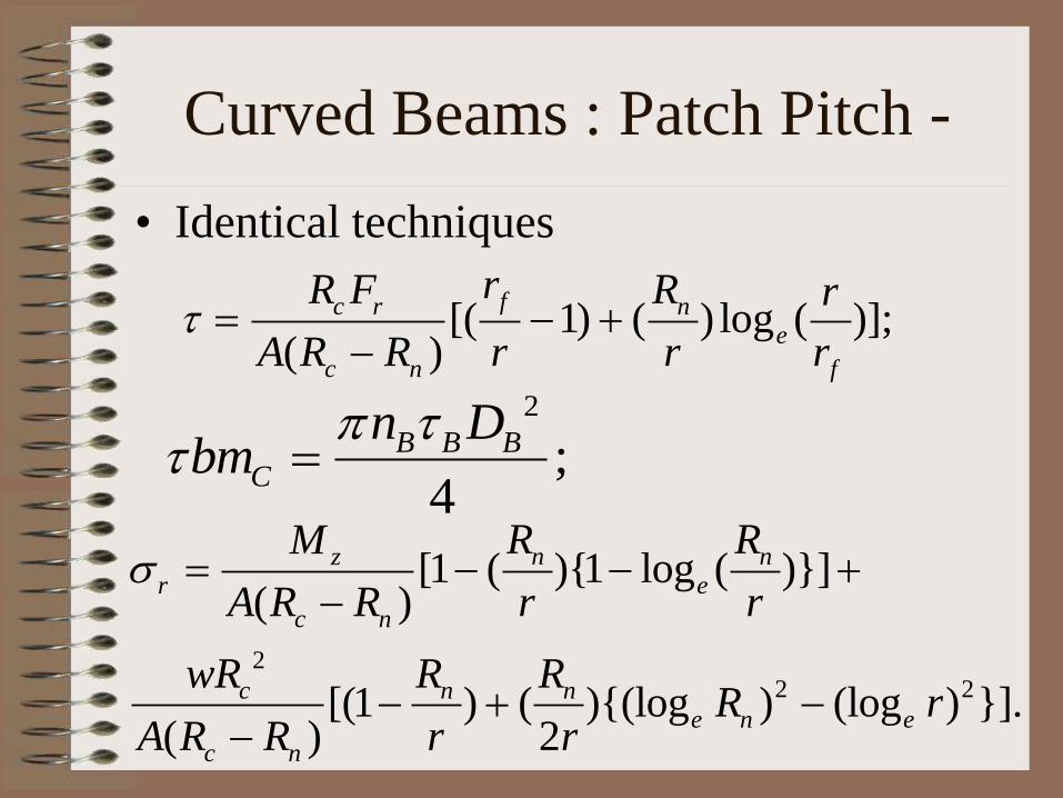
Curved Beams : Patch Pitch -
• Identical techniques
2
2 2
[1 ( )1 log ( )]( )
[(1 ) ( )(log ) (log ) ].( ) 2
n nzr e
c n
c n n
e n e
c n
R RM
A R R r r
wR R RR r
A R R r r
[( 1) ( ) log ( )];( )
fc r n
e
c n f
rR F R r
A R R r r r
2
;4
B B B
C
n Dbm
ER LTO & TSO : ICF -
• Minimum Solebar splicing length = 3ft, but
the welded joint should not be in the
doorway, body bolster & crossbar regions
• Maximum 1ft length in outer headstock
upper flange can be match patched by butt
welding no lap welding allowed just as in
body panels
Corrosion vulnerability : ICF -
• All MS trough floors in the vicinity of doorway
for ICF coaches are vulnerable
• Solebars, Turnunders, Body panels, Body pillars
neighbouring lavatory, doorways & pantry car
kitchen are vulnerable
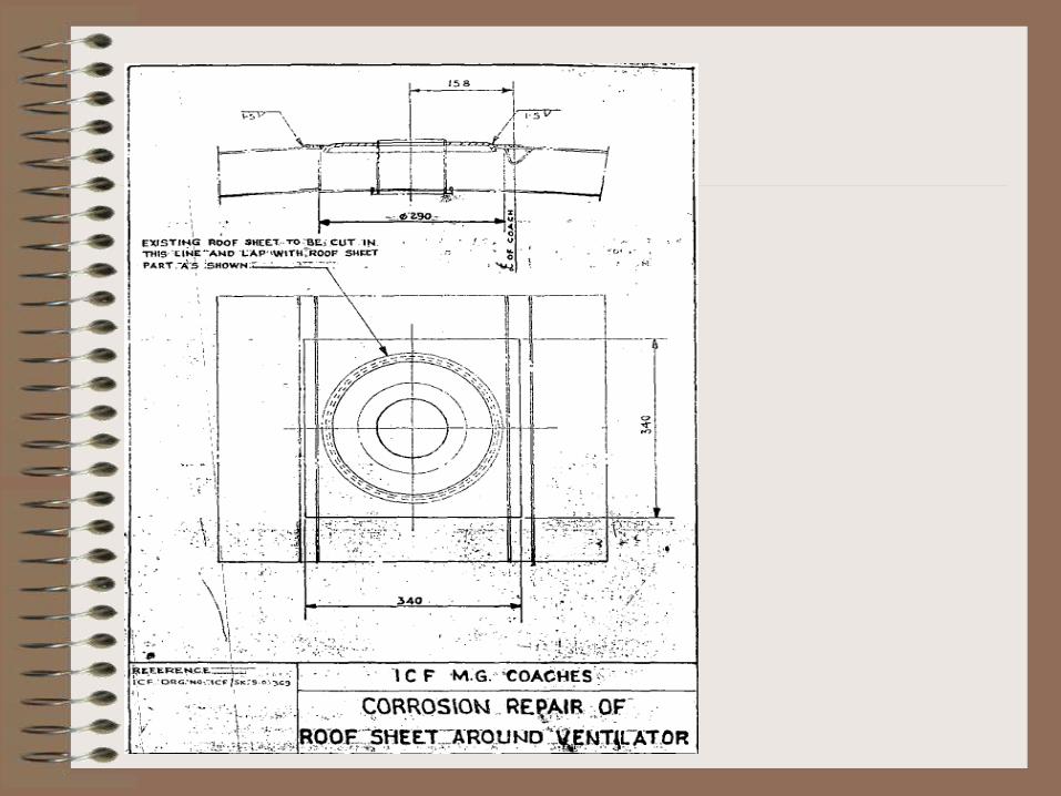
• Roof ventilators roof sheets are not skin
tensioned are vulnerable if roof is depressed
around ventilators
• 1.8 mm thick U channel water wriggles
rainwater gutters are vulnerable if there is
stagnant rainwater
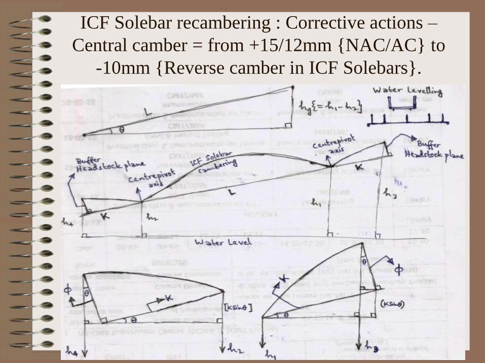
ICF Solebar recambering : Corrective actions –
Central camber = from +15/12mm NAC/AC to
-10mm Reverse camber in ICF Solebars.

ICF Solebar Recambering : Headstock ends –
Corrosion Repairs in Coaches.
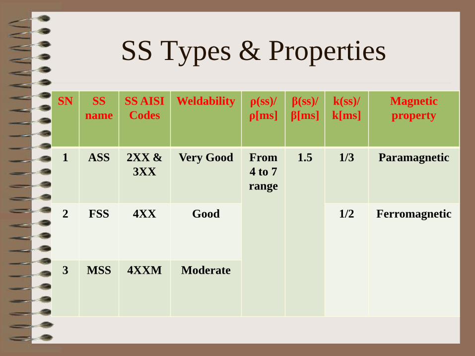
SS Types & Properties
SN SS
name
SS AISI
Codes
Weldability
ρ(ss)/
ρ[ms]
β(ss)/
β[ms]
k(ss)/
k[ms]
Magnetic
property
1 ASS 2XX &
3XX
Very Good From
4 to 7
range
1.5 1/3 Paramagnetic
2 FSS 4XX Good 1/2 Ferromagnetic
3 MSS 4XXM Moderate
SS Welding & Cutting
• SS has a 90micra Chromium Oxide passive film
with a melting point higher than the base metal
Fe
• Cannot be cut in Oxy Acetylene gas flame
• Can only be plasma cut or arc cut using N class
special electrode
• Low heat input electrode selected in arc welding
having less stub diameter & length
• MAG CO2 welding in ASS is not allowed
susceptible to weld decays

Weld decay: Sensitising in ASS-
• C has greater affinity towards Cr than Fe
• Chromium Carbide complex is precipitated at grain
boundaries if C content in ASS is more than 0.03%
• Cr depletion in ASS grains for formation of protective
Chromium Oxide film
• Grains suffer Oxidation PBR is low in Fe
• Cr must be redissolved at high sensitising temperatures
around 700 deg. Celsius from Carbides to prevent weld
decays in SS grains
• Nb, Cb, Ti with greater affinity towards C than Cr is
havingare added to ASS for prevention of this granular
corrosion
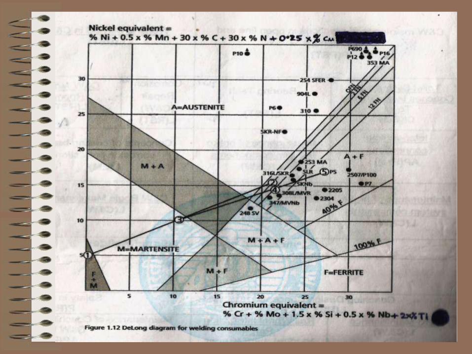
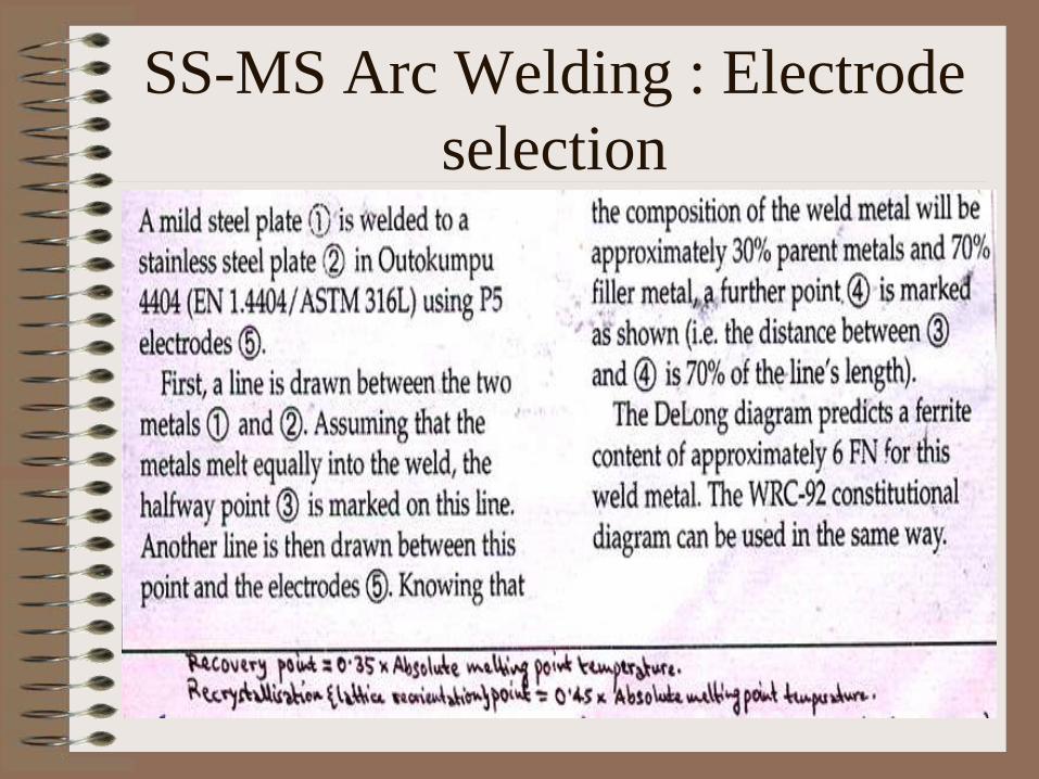
SS-MS Arc Welding : Electrode
selection
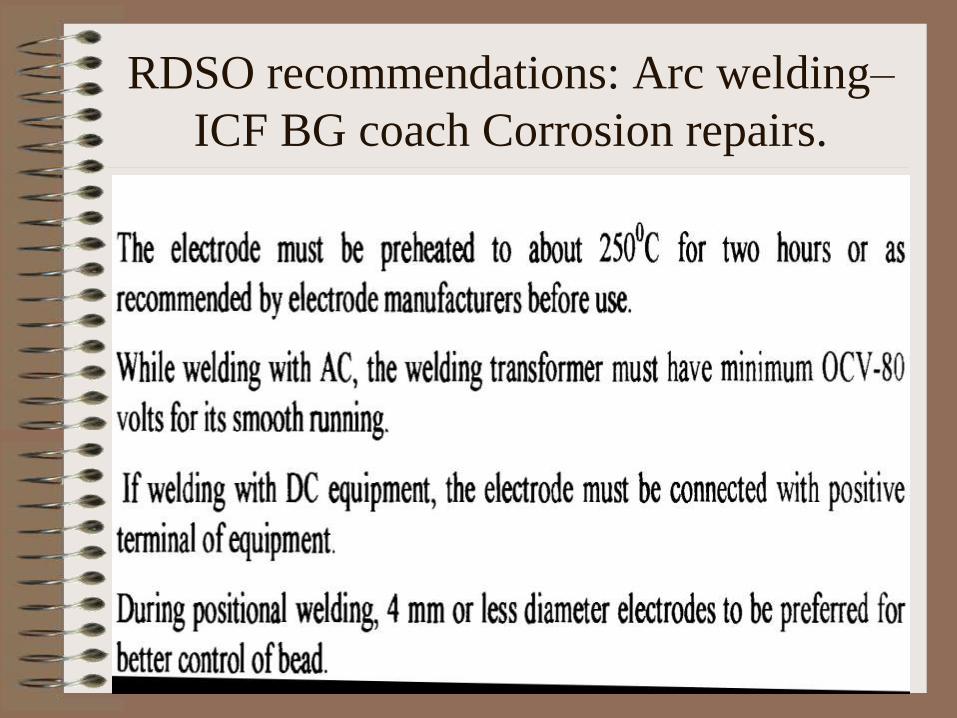
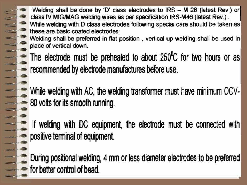
RDSO recommendations: Arc welding–
ICF BG coach Corrosion repairs.

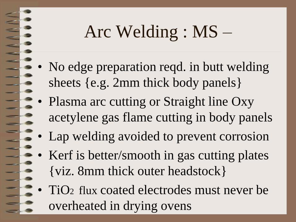
Arc Welding : MS –
• No edge preparation reqd. in butt welding
sheets e.g. 2mm thick body panels
• Plasma arc cutting or Straight line Oxy
acetylene gas flame cutting in body panels
• Lap welding avoided to prevent corrosion
• Kerf is better/smooth in gas cutting plates
viz. 8mm thick outer headstock
• TiO2 flux coated electrodes must never be
overheated in drying ovens
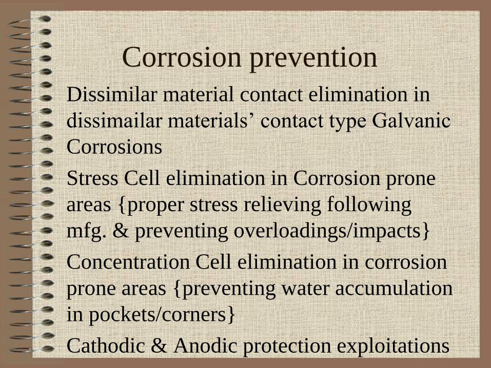
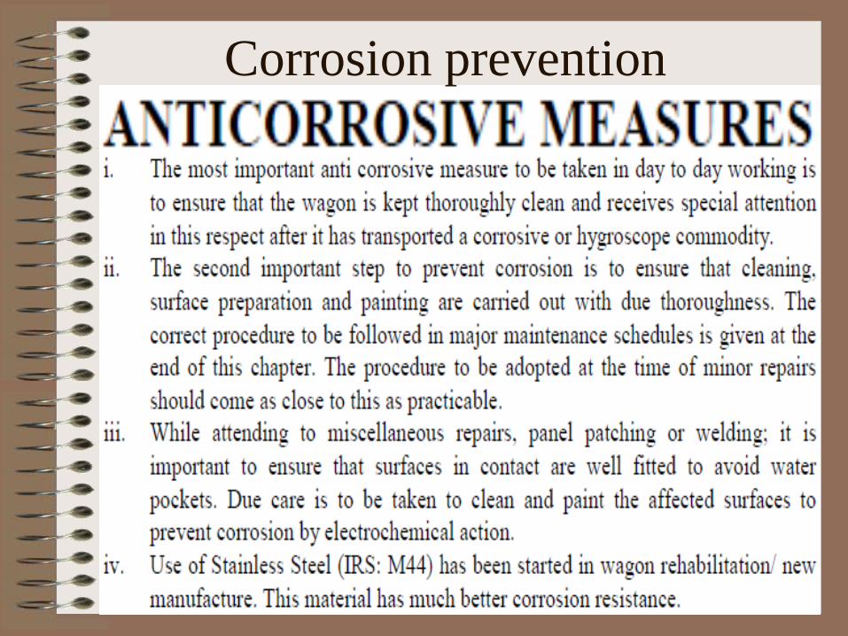
Corrosion prevention
Dissimilar material contact elimination in
dissimailar materials’ contact type Galvanic
Corrosions
Stress Cell elimination in Corrosion prone
areas proper stress relieving following
mfg. & preventing overloadings/impacts
Concentration Cell elimination in corrosion
prone areas preventing water accumulation
in pockets/corners
Cathodic & Anodic protection exploitations
Corrosion prevention
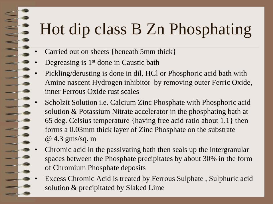
Hot dip class B Zn Phosphating
• Carried out on sheets beneath 5mm thick
• Degreasing is 1st done in Caustic bath
• Pickling/derusting is done in dil. HCl or Phosphoric acid bath with
Amine nascent Hydrogen inhibitor by removing outer Ferric Oxide,
inner Ferrous Oxide rust scales
• Scholzit Solution i.e. Calcium Zinc Phosphate with Phosphoric acid
solution & Potassium Nitrate accelerator in the phosphating bath at
65 deg. Celsius temperature having free acid ratio about 1.1 then
forms a 0.03mm thick layer of Zinc Phosphate on the substrate
@ 4.3 gms/sq. m
• Chromic acid in the passivating bath then seals up the intergranular
spaces between the Phosphate precipitates by about 30% in the form
of Chromium Phosphate deposits
• Excess Chromic Acid is treated by Ferrous Sulphate , Sulphuric acid
solution & precipitated by Slaked Lime
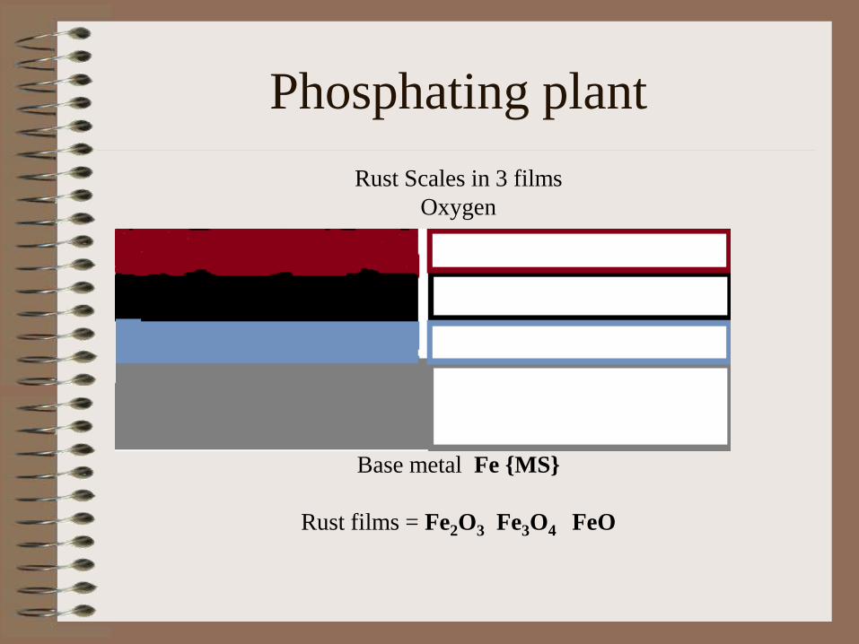
Phosphating plant
Rust Scales in 3 films
Oxygen
Base metal Fe MS
Rust films = Fe2O3 Fe3O4 FeO
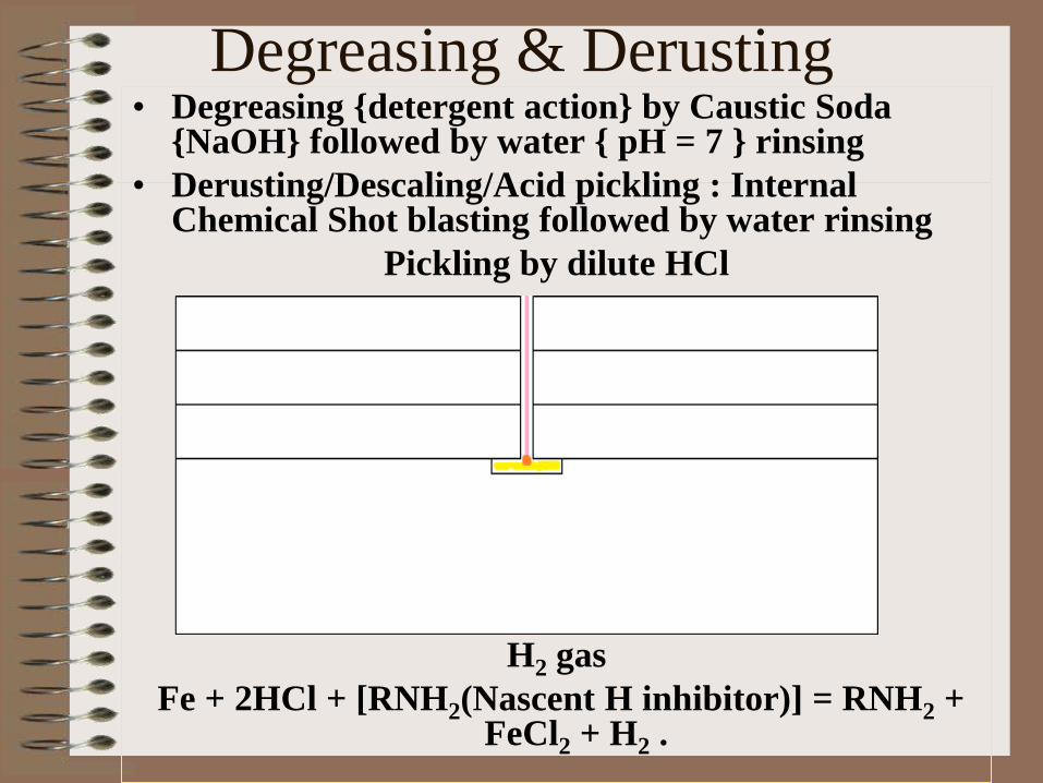
Degreasing & Derusting • Degreasing detergent action by Caustic Soda
NaOH followed by water pH = 7 rinsing
• Derusting/Descaling/Acid pickling : Internal Chemical Shot blasting followed by water rinsing
Pickling by dilute HCl
Pickling by dilute HCl
H2 gas
Fe + 2HCl + [RNH2(Nascent H inhibitor)] = RNH2 + FeCl2 + H2 .
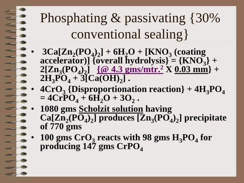
Phosphating & passivating 30%
conventional sealing
• 3Ca[Zn2(PO4)2] + 6H2O + [KNO3 (coating accelerator)] overall hydrolysis = KNO3 + 2[Zn3(PO4)2] @ 4.3 gms/mtr.2 X 0.03 mm + 2H3PO4 + 3[Ca(OH)2] .
• 4CrO3 Disproportionation reaction + 4H3PO4 = 4CrPO4 + 6H2O + 3O2 .
• 1080 gms Scholzit solution having Ca[Zn2(PO4)2] produces [Zn3(PO4)2] precipitate of 770 gms
• 100 gms CrO3 reacts with 98 gms H3PO4 for producing 147 gms CrPO4

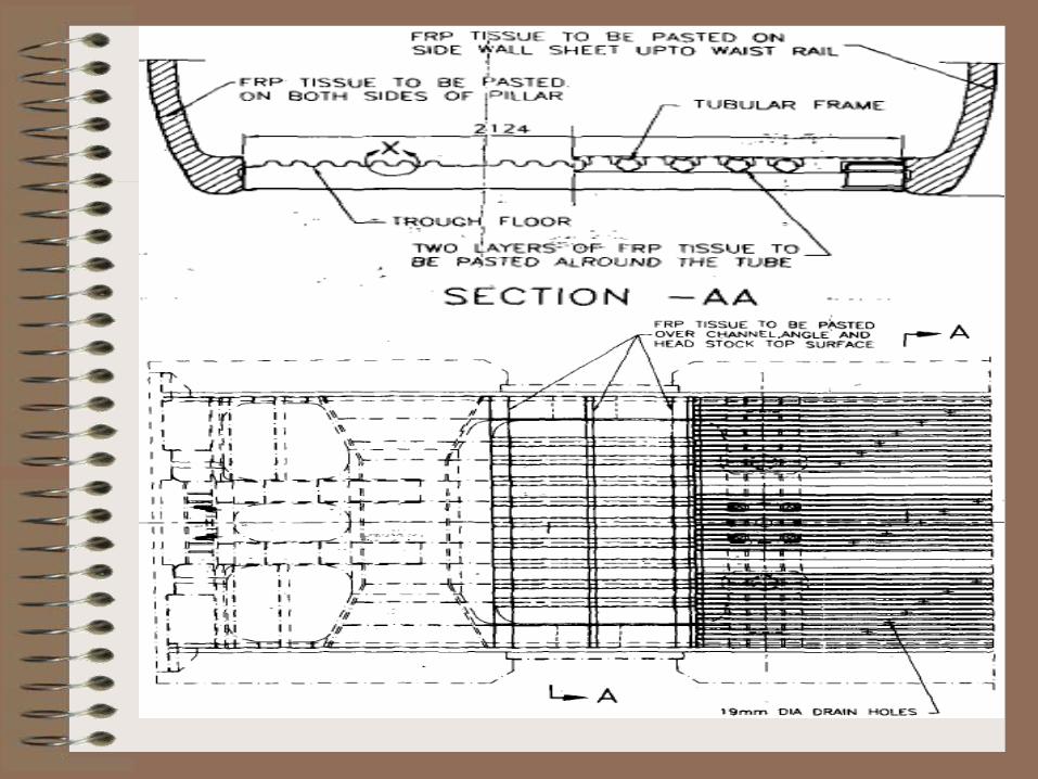
Anticorrosive treatments : ICF –
• Battery box frames are hot galvanised
• FRP tissue papers are pasted in layers on
MS trough floors keeping drain holes open
& following RDSO instructions
• Black bituminous paint is done over ROZ
primer coatings
• Electrostatic PU spray painting following
grit blasting on cleaned exterior surfaces &
powder coatings on interior MS fittings
CORROSION ON
BOX/BOXN/BOBRN
WAGONS i.e. Open type
Wagons
CR BOX BOXN BOBRN
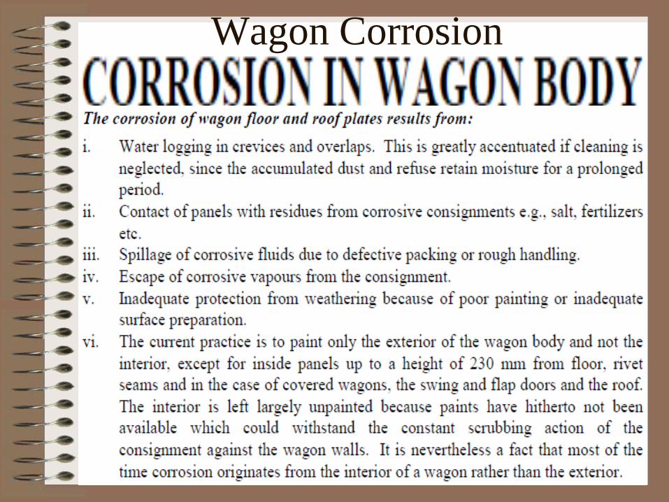
Wagon Corrosion
FACTORS RELATED TO CORROSION :-
1. Types of commodities loaded.
2. Pattern of loading.
3. Contamination of rain water with the
Chemical substance.
4 . Running through coastal areas.
5. Stagnation of rain water.
6. Overlapping of panel plates.
7. Improper painting without surface
preparations.
Corrosion : Phenomenon -
1. STRESSED END PANELS AND STANCHIONS BY
BAD LOADING OF MATERIAL AND LOOSE
SHUNTING IMPACTS.
2. ACCUMULATION OF RAIN WATER
CONTAMINATED WITH CHEMICALS OF
MATERIAL LOADED.
3. STAGNATION OF RAIN WATER ON THE FLOOR.
4. SEEPAGE OF RAIN WATER FROM
FLOOR TO THE SOLEBAR NEAR DOOR WAY.
5. DOOR HINGES IN CONTACT WITH MOISTURE.
Corrosion : Reasons -

1. End Panels.
2. Side panels.
3. Floor.
4. Door panels, hinges, frames.
5. Body and end stanchions.
6. Sole bar near doorway.
7. Bulging out of side panels.
8. Corner and Top copings.
Corrosion Prone regions : Wagons -
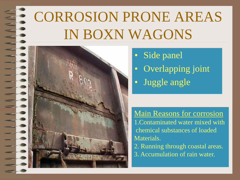
CORROSION PRONE AREAS
IN BOXN WAGONS
• Side panel
• Overlapping joint
• Juggle angle
Main Reasons for corrosion 1.Contaminated water mixed with
chemical substances of loaded
Materials.
2. Running through coastal areas.
3. Accumulation of rain water.

CORROSION PRONE AREAS
• End stanchion
• Tarpaulin
cleats
Corrosion takes place
by impacts during
loose shunting
accelerated
in contact with
Rain water and
moisture.
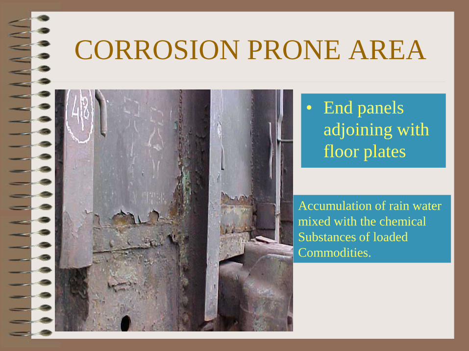
CORROSION PRONE AREA
• End panels
adjoining with
floor plates
Accumulation of rain water
mixed with the chemical
Substances of loaded
Commodities.

CORRODED AND FINALLY BROKEN
Corrosion took place on the side coping channels due to rain water
ingress. During unloading by tipplers the weak portion is
Broken.
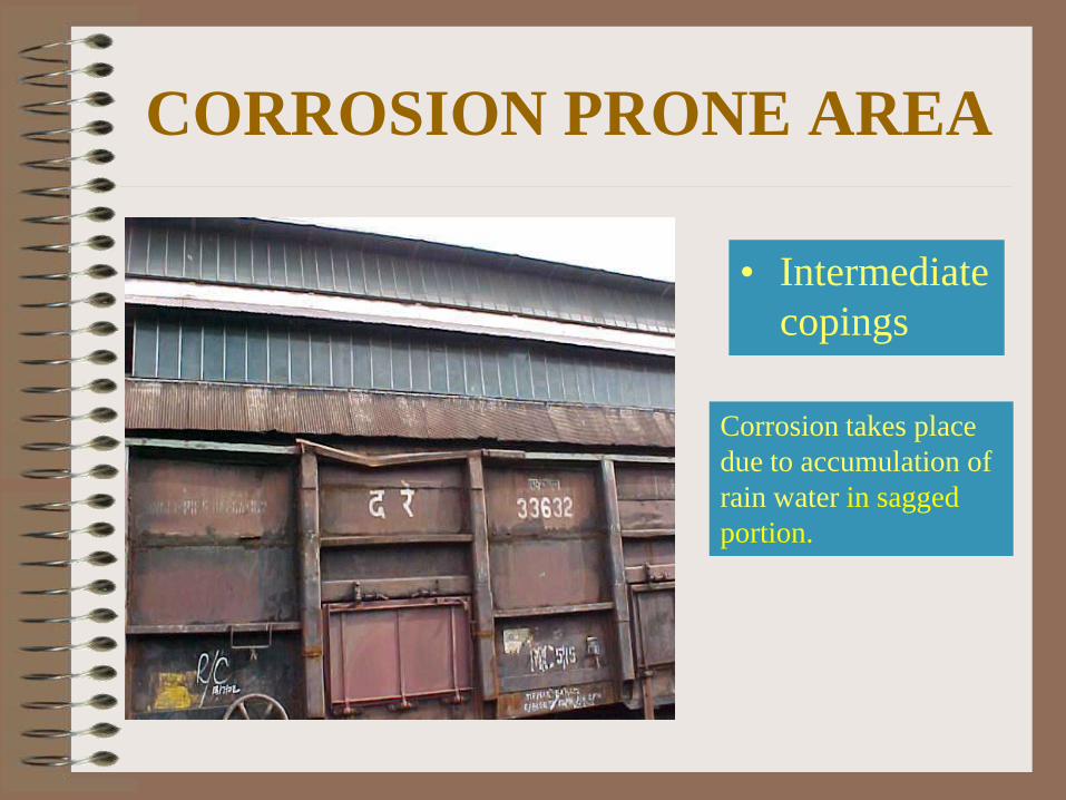
CORROSION PRONE AREA
• Intermediate
copings
Corrosion takes place
due to accumulation of
rain water in sagged
portion.
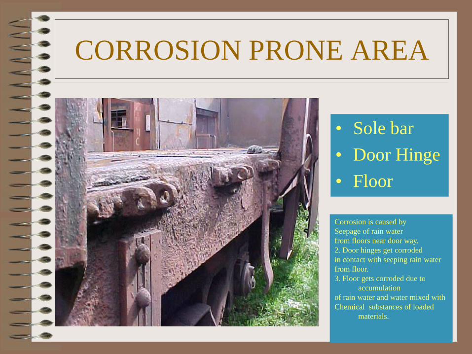
CORROSION PRONE AREA
• Sole bar
• Door Hinge
• Floor
Corrosion is caused by
Seepage of rain water
from floors near door way.
2. Door hinges get corroded
in contact with seeping rain water
from floor.
3. Floor gets corroded due to
accumulation
of rain water and water mixed with
Chemical substances of loaded
materials.
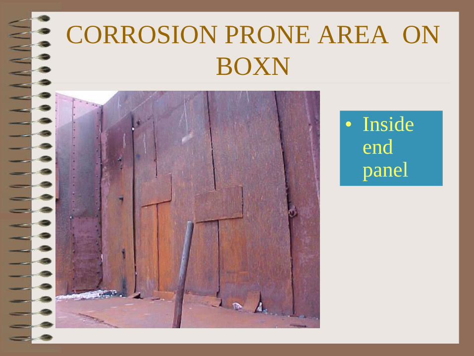
CORROSION PRONE AREA ON
BOXN
• Inside end panel

Corrosion Prone Area On
BOXN
• Corner angles
• Side and end top Channels
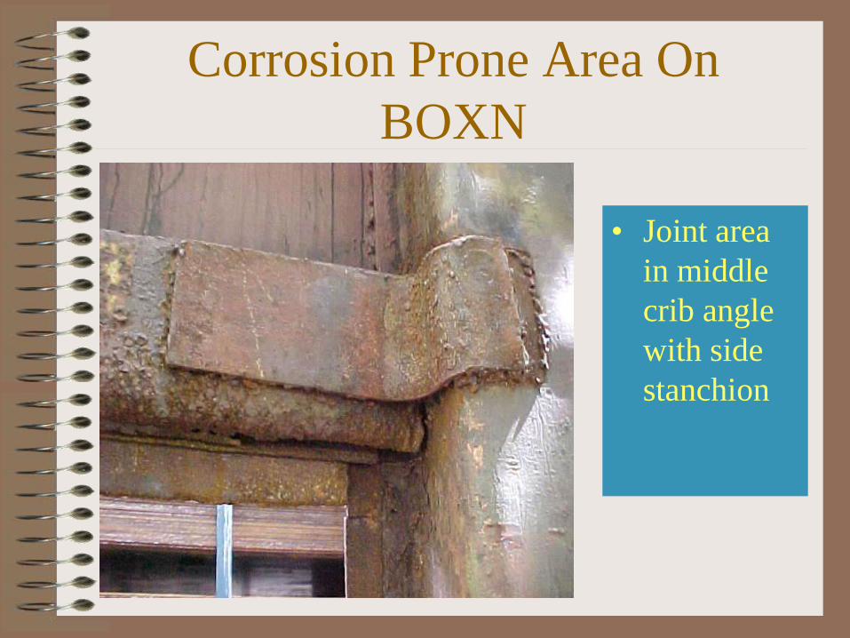
Corrosion Prone Area On
BOXN
• Joint area
in middle
crib angle
with side
stanchion

Corrosion Prone Area on
BOXN
• Door
frame
• Door
Hinge

Corrosion Prone Area on
BOXN
Plate over
joint of
side panel
and floor.
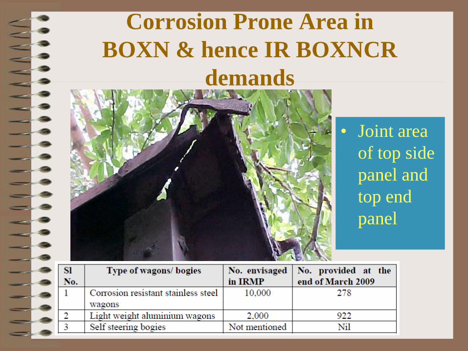
Corrosion Prone Area in
BOXN & hence IR BOXNCR
demands
• Joint area
of top side
panel and
top end
panel
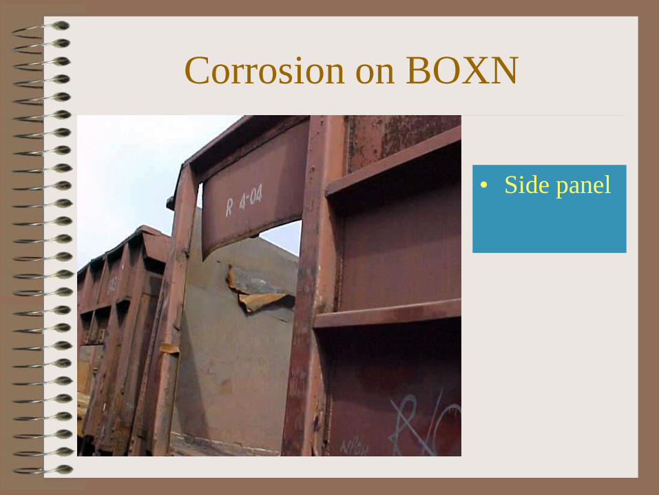
Corrosion on BOXN
• Side panel
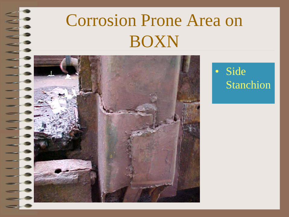
Corrosion Prone Area on
BOXN
• Side
Stanchion
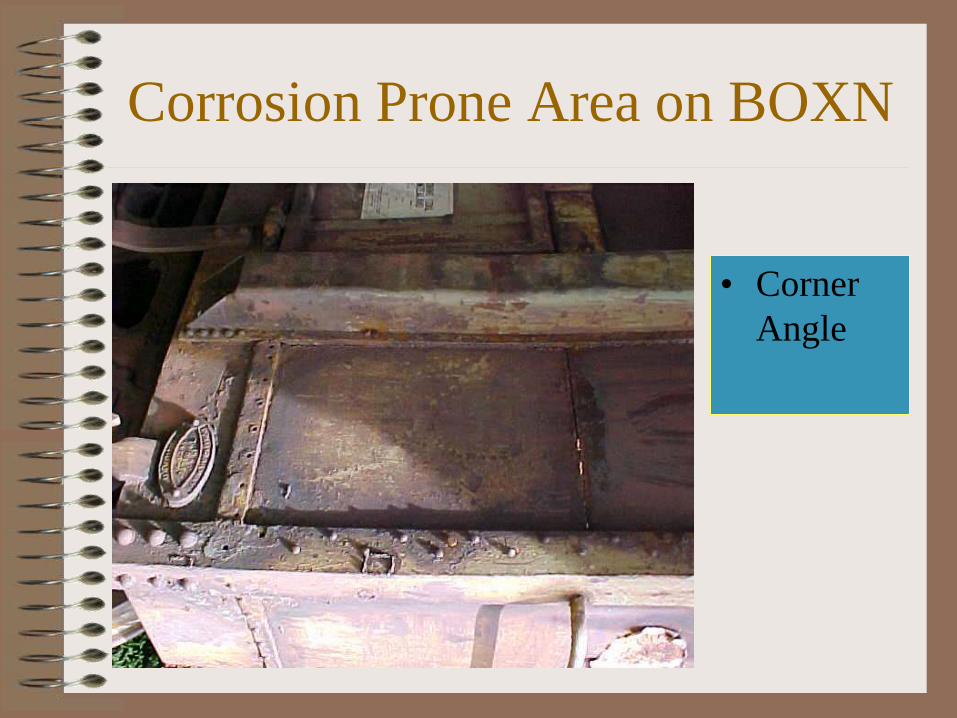
Corrosion Prone Area on BOXN
• Corner
Angle
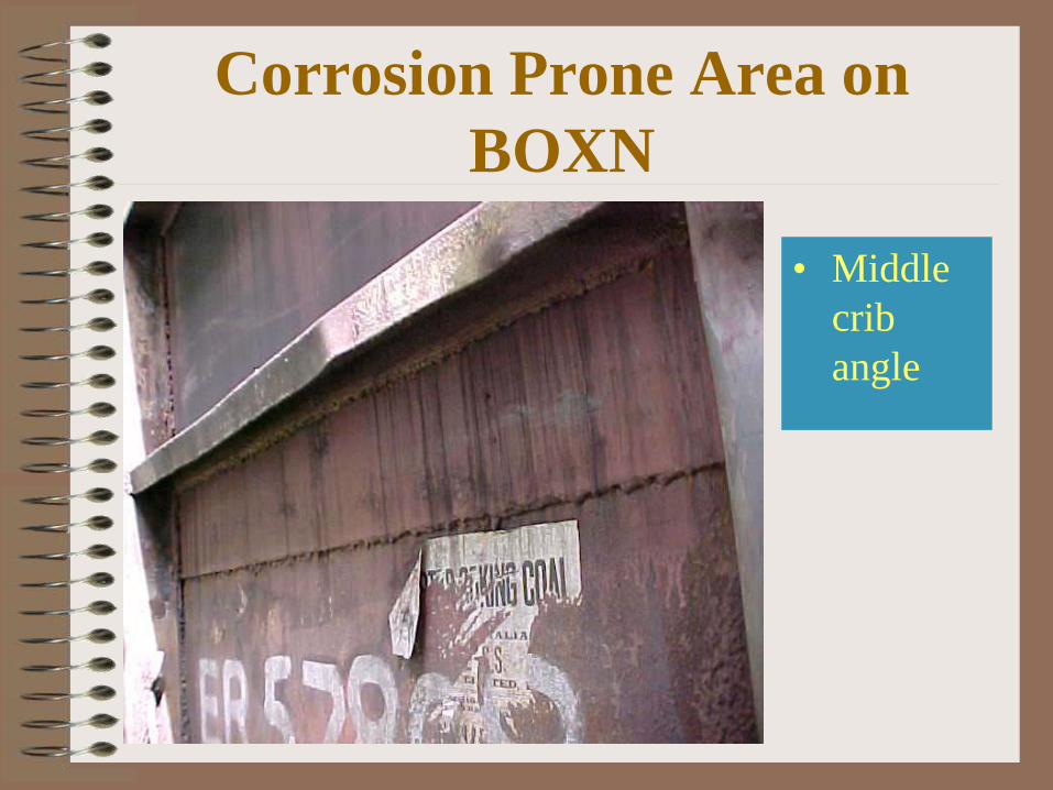
Corrosion Prone Area on
BOXN
• Middle
crib
angle
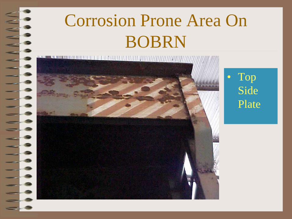
Corrosion Prone Area On
BOBRN
• Top
Side
Plate
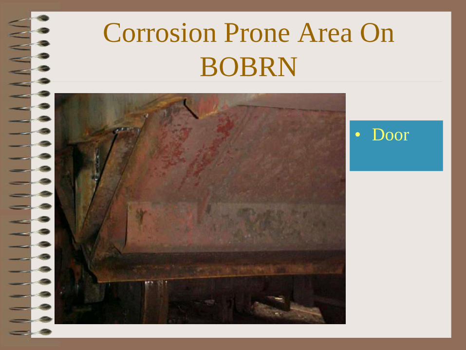
Corrosion Prone Area On
BOBRN
• Door
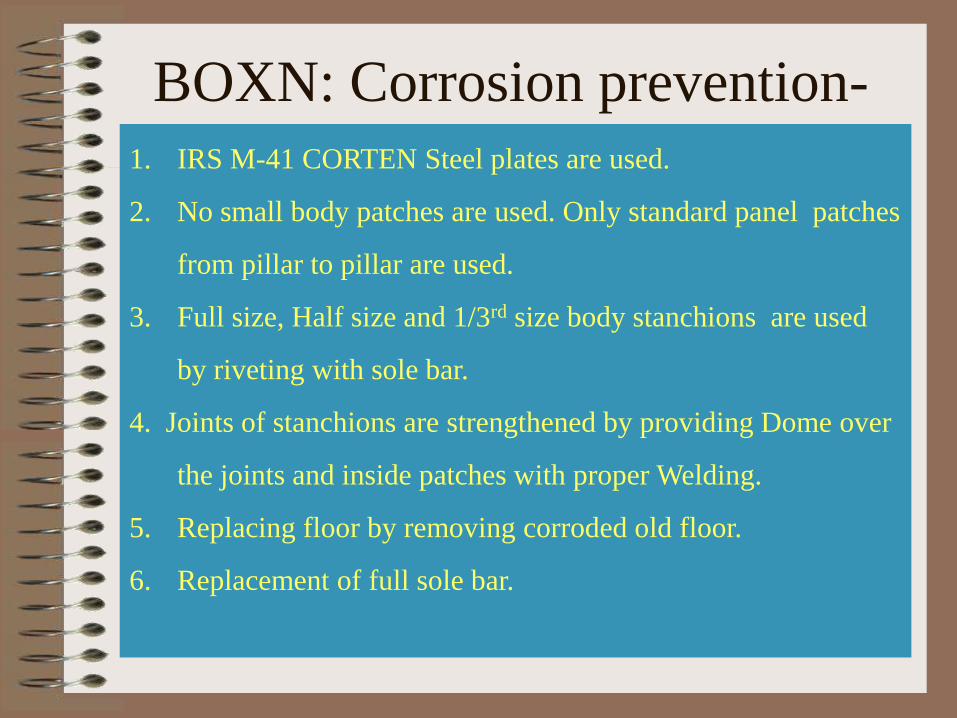
1. IRS M-41 CORTEN Steel plates are used.
2. No small body patches are used. Only standard panel patches
from pillar to pillar are used.
3. Full size, Half size and 1/3rd size body stanchions are used
by riveting with sole bar.
4. Joints of stanchions are strengthened by providing Dome over
the joints and inside patches with proper Welding.
5. Replacing floor by removing corroded old floor.
6. Replacement of full sole bar.
BOXN: Corrosion prevention-
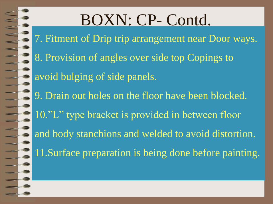
7. Fitment of Drip trip arrangement near Door ways.
8. Provision of angles over side top Copings to
avoid bulging of side panels.
9. Drain out holes on the floor have been blocked.
10.”L” type bracket is provided in between floor
and body stanchions and welded to avoid distortion.
11.Surface preparation is being done before painting.
BOXN: CP- Contd.

Why BOXN wagons are the
most corrosion prone ones
among Open top wagons ?
• BOBRN/BOBYN Bogie type
bottom/side discharge hopper wagon has
inclined flooring which helps rainwater to
automatically drain out from floor
• BOXN Bogie type open box wagon has
flat floor for accumulation of rainwater
• BRN Bogie type open flat form wagon
has no damming wall that can hold water
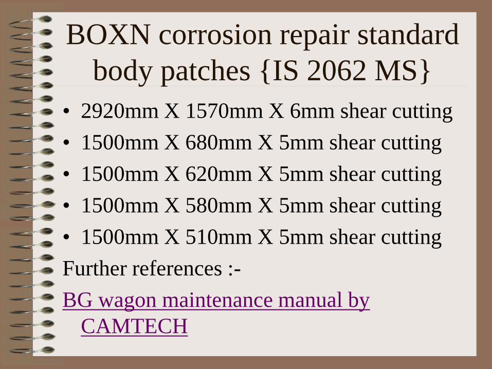
BOXN corrosion repair standard
body patches IS 2062 MS
• 2920mm X 1570mm X 6mm shear cutting
• 1500mm X 680mm X 5mm shear cutting
• 1500mm X 620mm X 5mm shear cutting
• 1500mm X 580mm X 5mm shear cutting
• 1500mm X 510mm X 5mm shear cutting
Further references :-
BG wagon maintenance manual by
CAMTECH
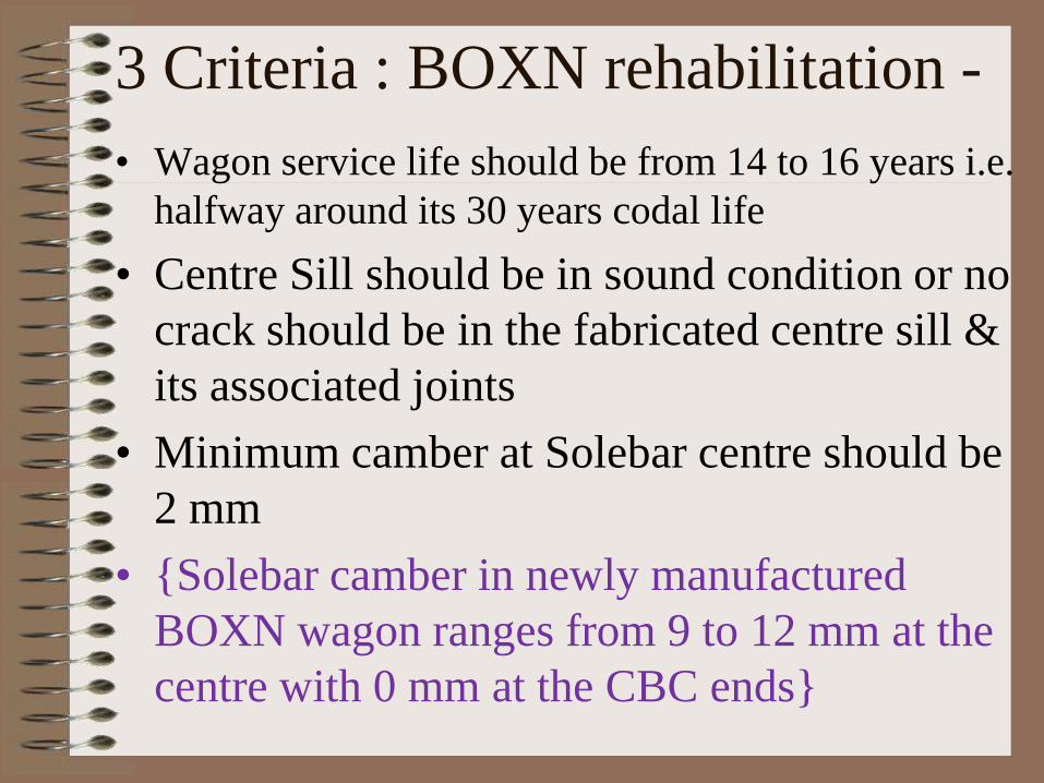
3 Criteria : BOXN rehabilitation -
• Wagon service life should be from 14 to 16 years i.e.
halfway around its 30 years codal life
• Centre Sill should be in sound condition or no
crack should be in the fabricated centre sill &
its associated joints
• Minimum camber at Solebar centre should be
2 mm
• Solebar camber in newly manufactured
BOXN wagon ranges from 9 to 12 mm at the
centre with 0 mm at the CBC ends
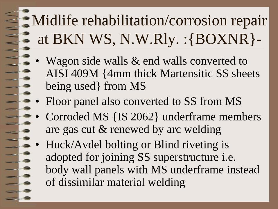
Midlife rehabilitation/corrosion repair
at BKN WS, N.W.Rly. :BOXNR-
• Wagon side walls & end walls converted to AISI 409M 4mm thick Martensitic SS sheets being used from MS
• Floor panel also converted to SS from MS
• Corroded MS IS 2062 underframe members are gas cut & renewed by arc welding
• Huck/Avdel bolting or Blind riveting is adopted for joining SS superstructure i.e. body wall panels with MS underframe instead of dissimilar material welding

BOXNHL & BCNHL specialities
• 10 mm thick seamfree cold pressed hat
section of SS for the one piece Centre Sill
• 4 mm thick AISI 409M U pressed channel
section body side & end stanchions
• SS floor panel in BOXNHL
• All corrosion resistant materials
• Twin pipe Air Brake System in both
BCNHL = 20.9T tare + 70.9T CC
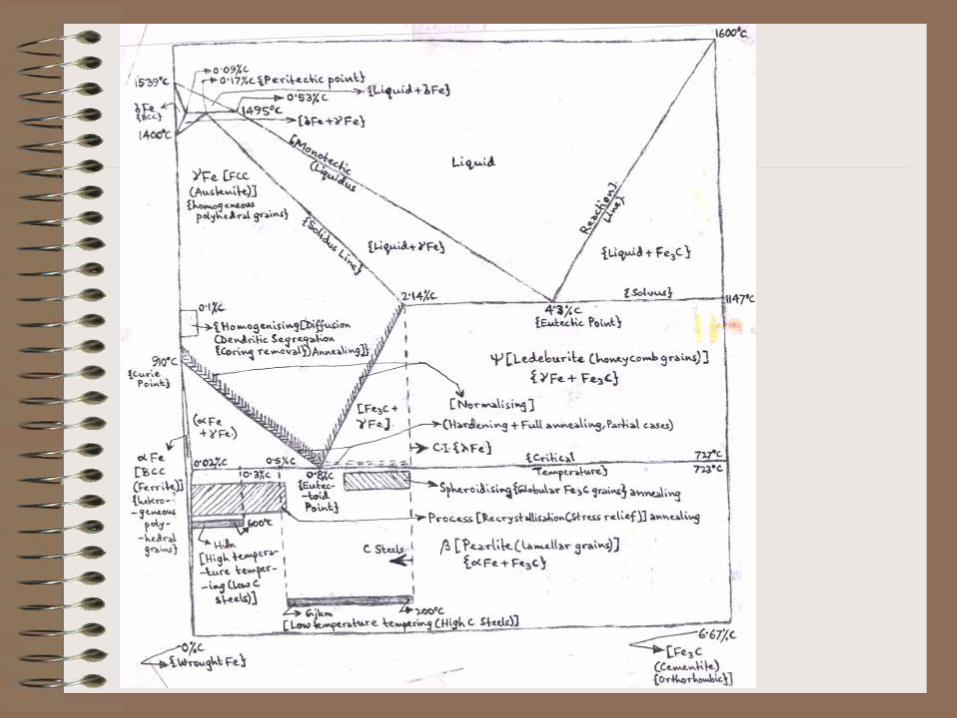
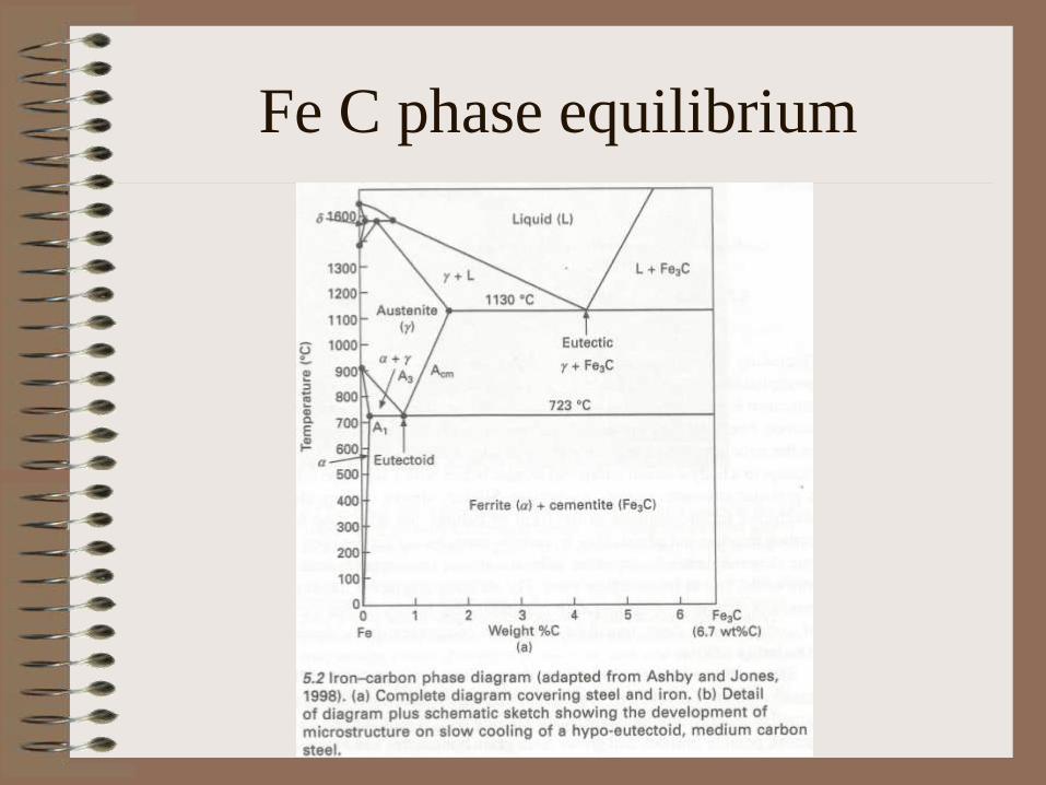
Fe C phase equilibrium
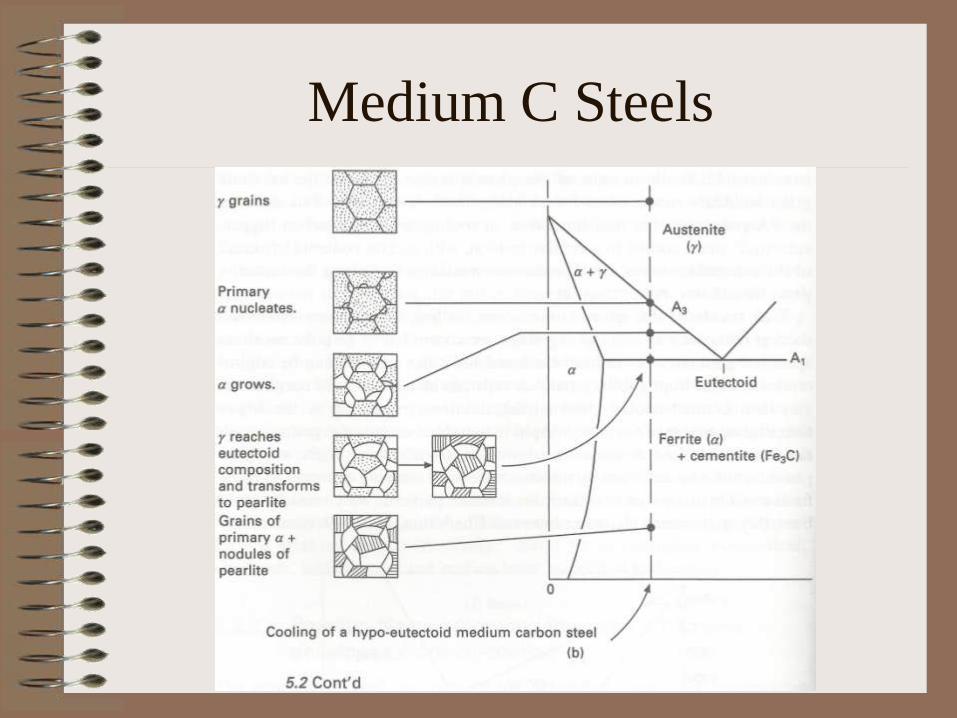
Medium C Steels

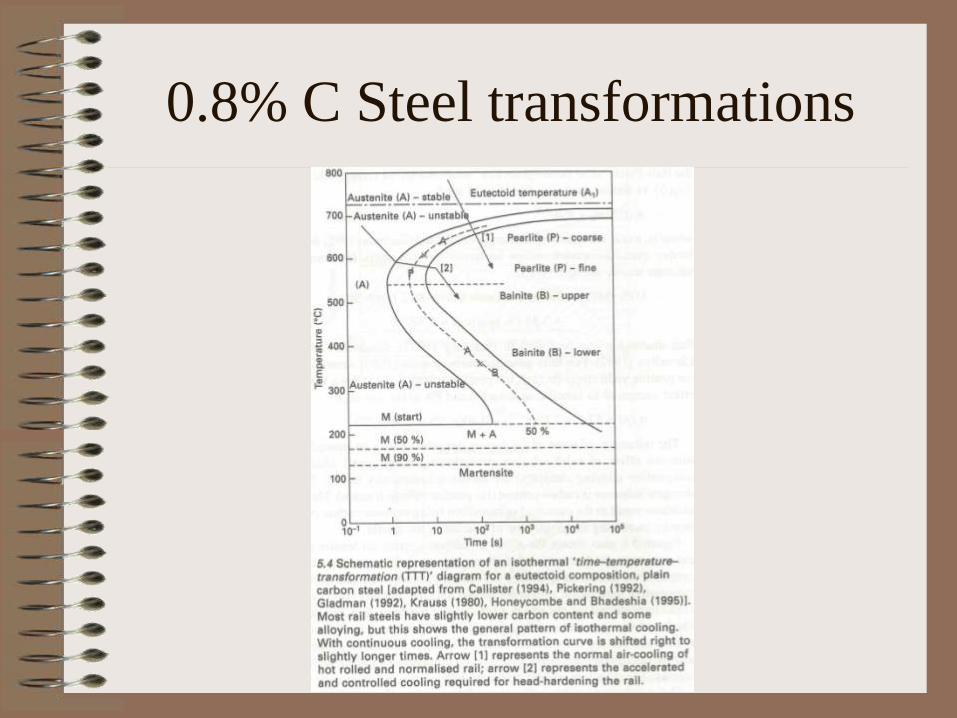
0.8% C Steel transformations
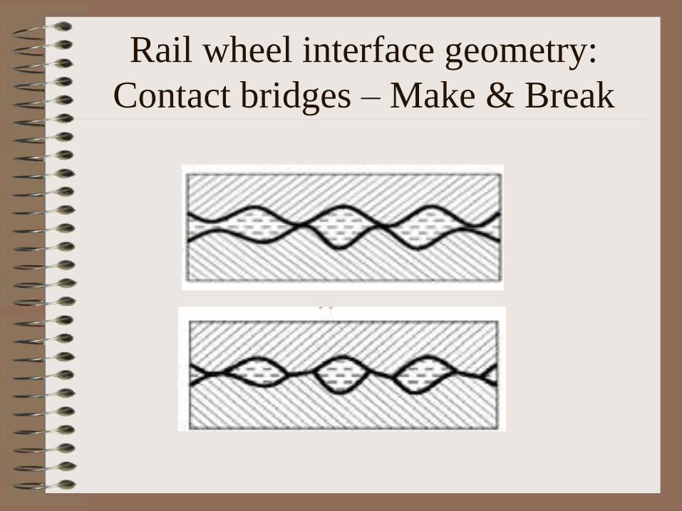
Rail wheel interface geometry:
Contact bridges – Make & Break

:

Creep = Wheel’s Angular velocity X Wheel’s
rail contact radius - Vehicle speed
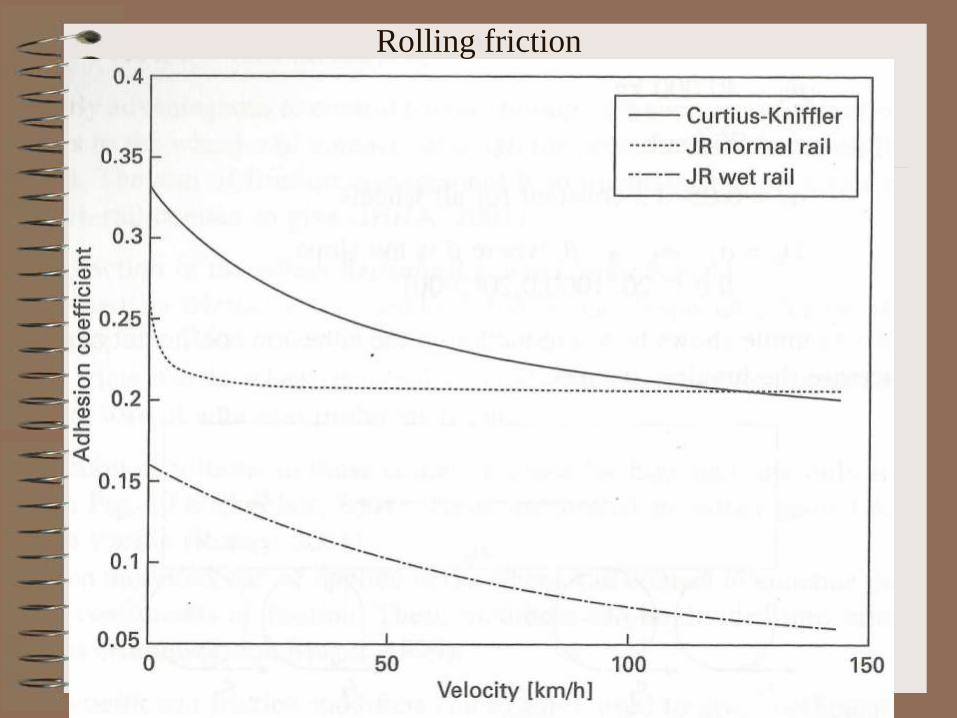
Rolling friction
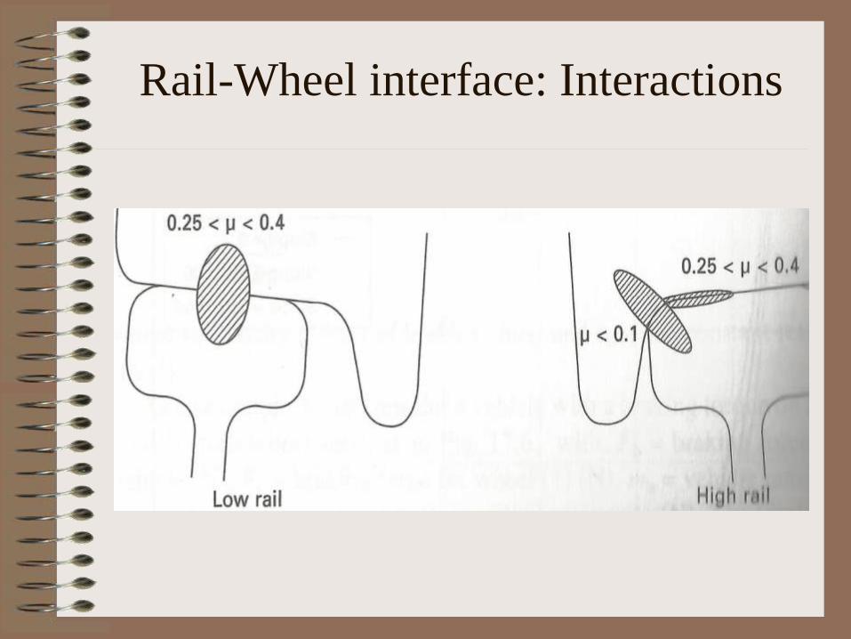
Rail-Wheel interface: Interactions
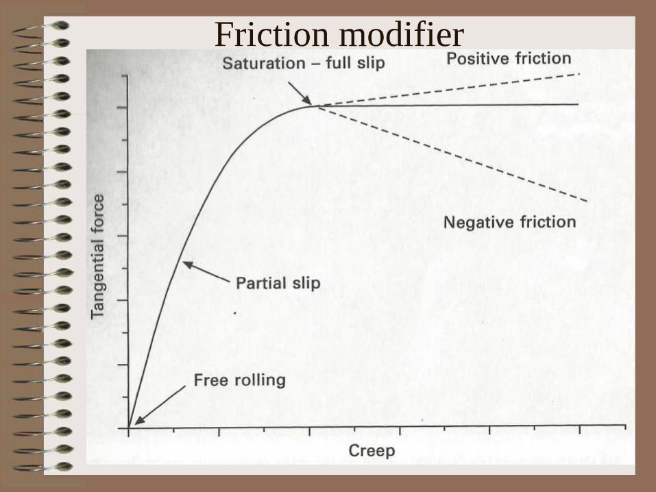
Friction modifier
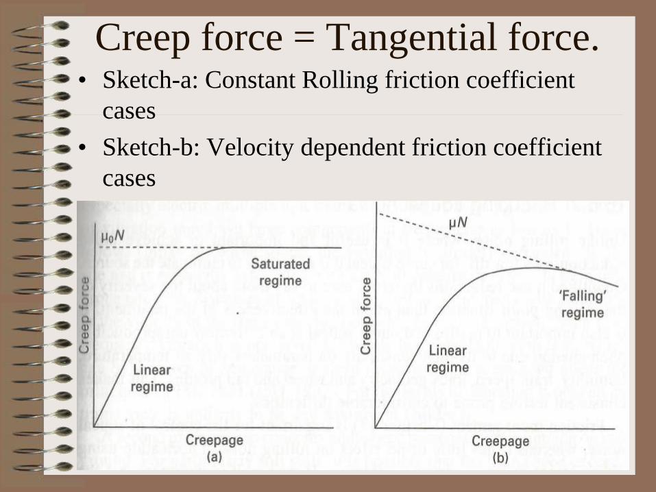
Creep force = Tangential force. • Sketch-a: Constant Rolling friction coefficient
cases
• Sketch-b: Velocity dependent friction coefficient
cases
Corrosion: Definition-
• Corrosion is a slow spontaneous
electrochemical in situ degradation of
materials in environment which results in
loss of section and subsequently of
strength.
• Corrosion in steel is reverse extractive
metallurgy obeying thermodynamics’ 2nd
Law in an Oxidising environment.
REASONS FOR CORROSION
1. Concentration Cell formation by water accumulation :
Net corrodent influx in Corrodent i.e. Oxygen starved
region by Continuous Diffusion along Concentration
gradient : this becomes Anode vis-à-vis Oxygen
abundant region & gets corroded by the Corrodent.
2. Stress Cell formation by unrelieved tensile stresses :
Tensile stress opens up surface cracks : Residual stress
gives excessive free or activation energy in this region
vis-à-vis the relatively unstressed region thereby
forming Anode in the Galvanic Cell & selectively
corroding it by the surrounding corrodent.
REASONS OF CORROSION
Contd.
3. Dissimilar materials’ contact : More
electropositive material becomes the Anodic
i.e. +ve electrode half Cell & gets corroded by
the corrodent in Electrolysis type Chemical
Reaction – Less electropositive material
becomes the Cathodic i.e. –ve electrode half
Cell & gets protected in this completed Galvanic
Cell/Circuit.
4. Dry Oxidative Coulomb friction heat induced
Corrosion i.e. Fretting.
Pilling Bedworth Ratio : PBR -
• PBR = Oxide film volume/Oxidised metal volume in
oxidative corrosion
• Filiform Corrosion = Wet electrolyte accelerated
galvanic corrosion corrosion filament in rust has
bluish green active head & a long reddish brown
passive tail
• PBR = or > 1 means protective film logarithmic film
growth rate rising over parabolic rate but may give
spalling [exfoliation (weathering rocks’ peeling)] in
ceramics
• PBR < 1 means catastrophic oxidation of porous
oxide film linear rate for alkali metals mainly

Thank You


![AGENDA ITEM FORM - dmww.com · corrosion control program ([1] Anode Retrofit Program, [2] Anode Installation During Main Break Repairs , [3] Corrosion Protection on New Small Ductile](https://img.dokumen.tips/doc/110x75/60e3c08f7d9f13103926d0c5/agenda-item-form-dmww-corrosion-control-program-1-anode-retrofit-program.jpg)