Embed Size (px)
Citation preview

372 DOI: 10.1002/maco.200805132 Materials and Corrosion 2009, 60, No. 5
Corrosion protection of sintered NdFeBmagnets by CAPVD Ti2N coating
A. Ali* and A. Ahmad
Sintered NdFeB magnets have poor corrosion resistance and arereadily susceptible to corrosion under different environmentalconditions. Cathodic arc physical vapour deposited (CAPVD)titanium nitride coating for sintered NdFeB permanent magnetshas been investigated in this paper. Tafel extrapolation wasemployed to study the corrosion behaviour in 3.5% NaCl solutionat ambient temperature. The adhesive strength of the coating wasestimated with the help of the scratch test. The surface chemistryand coating morphologies were studied with scanning electronmicroscope (SEM). X-Ray diffraction (XRD) was used for qual-
� A. Ali, A. AhmadMetallurgical and Materials Engineering, Baghbanpura Lahore,University of Engineering and Technology, Lahore, Punjab54000 (Pakistan)E-mail: [email protected]
www.wiley-vch.de/home/wuk � 2009 WILEY-VCH Verlag Gm
itative phase analyses of coatings and substrate. The properties ofCAPVD titanium nitride coating were compared with electrode-posited multilayer nickel–copper–nickel coating. It was figured outthat the CAPVD titanium nitride coating had better adhesionstrength and shifted the free corrosion potential (FCP) of the systemtowards positive potential, providing protection to the NdFeBsubstrate. However, the corrosion rate of CAPVD titanium nitridecoating was more than the electrodeposited multilayer nickel–copper–nickel coating. The magnetic properties remained compar-able.
1 Introduction
The NdFeB permanent magnets, discovered in 1983 [1–3],are important technological materials owing to their highestenergy product at ambient temperature providing efficientuse of electrical energy and having wide applications invarious industries [4]. The sintered NdFeB magnets haverelatively poor corrosion resistance in various environments[5,6] due to their complex microstructure [7] and thus needprotection against corrosion.
Efforts have been made to improve their corrosionresistance both by alloying additions [8–11] and by applyingprotective coatings [12–14]. A lot has been published on therole of metallic and epoxy coatings on the corrosionprotection of sintered NdFeB magnets but the literature onthe effect of ceramic coatings by cathodic arc physicalvapour deposition (CAPVD) is scarce. In this process, themetal vapours are ejected from the solid material at ambienttemperature employing plasma assisted high energy cathodicarc. The evaporated flux consists of ions that are acceleratedtowards the substrate due to the applied potential gradient.The kinetic energy of ions falls in the range of 10–100 eV.Nitrogen or methane is introduced to form nitride or carbideby combining with the evaporated metal ions. Titaniumnitride and titanium carbide coatings deposited by CAPVDhave been reported as extremely useful in improving thewear resistance of different types of steels including highspeed tool steels [15]. Titanium nitride possesses exceptionalqualities like high hardness, wear and corrosion resistancewith decorative gold like reflection.
The purpose of this work is to study the effect of CAPVDtitanium nitride coating on the corrosion resistance ofsintered NdFeB magnets with varying concentrations of
NaCl, H2SO4 and HF in comparison with multilayer Ni–Cu–Ni coating. The data with 3.5% NaCl are reported here only.
2 Experimental
2.1 Material
The substrate material used for this study was powdermetallurgically produced commercial sintered NdFeBmagnets. Table 1 gives the chemical composition of themagnet, determined through wet analysis, as boron was notdetected by EDS. The hydrostatic density of the sinteredNdFeB magnets used in this study was 7.58 g/cm3 whereastheir theoretical density is 7.60 g/cm3.
2.2 Sample size and preparation
Disc-shaped NdFeB magnets with 12 mm diameter and2.5 mm thickness were metallographically polished to 1.0 mmalumina suspension and ultrasonically cleaned in ultrasonicsoap solution at ambient temperature. For metallographicexamination the samples were etched in 2% nital.
2.3 CAPVD coating set up
The coating set up consisted of 70 mm diameter disc-shaped titanium target (cathode) having 99.99% purity,mounted on water cooled copper stage. The anode was alsodisc shaped with 250 mm diameter that was fixed at the top ofthe target with a perpendicular distance of 300 mm. Thepolished and cleaned substrates were mounted on a rotarysample holder at an angle of 308 with normal to the cathode.The rotational speed of the sample holder was 7 rpm. The
Table 1. Chemical composition of sintered NdFeB magnets
Element B Nd Fe
Wt% 1.26� 0.14 32.90� 0.35 Bal
bH & Co. KGaA, Weinheim

Materials and Corrosion 2009, 60, No. 5 Corrosion protection of sintered NdFeB magnets by CAPVD Ti2N coating 373
Table 2. Coating parameters for CAPVD titanium nitride coatingon sintered NdFeB magnets
CAPVD Ti2N coating parameter Value for present coating
Base pressure 10�2 PaCleaning arc current 90 ACleaning bias voltage 200 VCleaning time 600 sCoating arc current 80 ACoating bias voltage 80 VCleaning time 1800 sNitrogen partial pressure 0.8–4.6 Pa of base pressure
Table 3. Bath compositions and conditions for electrodeposition ofcopper and nickel
Nickel Copper
Bath composition 300 g/L H2SO4 � 6H2O 200 g/L CuSO4
45 g/L NiCl2 � 6H2O 60 g/L H2SO4
0.4 vol% anti-pitting agent(sulphated alcoholic salt)
–
Current density (A/dm2) 2 2.5Time (s) 5 10Temperature (8C) 60 50pH 5 2
whole assembly was enclosed in a double walled stainlesssteel chamber. The chamber was evacuated and finalcleaning was carried out by hollow cathode argon plasmadischarge in the chamber. An arc of 1.6 kVA was triggeredwith the help of grounded copper wire. The arc was operatedcontinuously for 30 min. Nitrogen was then introduced in thechamber through microprocessor controlled automaticfeeding system that controlled the nitrogen partial pressurein the chamber. The base pressure in the chamber was 10�2
Pa while nitrogen partial pressure can be adjusted in therange of 0.8–4.6 Pa of the base pressure during depositionperiod. The coating parameters are tabulated in Table 2.
2.4 Electrodeposition of multilayer Ni–Cu–Ni coating
The Watt’s solution was used for electrolytic nickeldeposition while copper sulphate bath was used for depo-siting copper. The bath composition and coating parametersare tabulated in Table 3. First, a strike layer of nickel was
Fig. 1. Optical micrographs showing coatings on the sectioned NdF
www.wiley-vch.de/home/wuk
deposited followed by copper and finally nickel. Thesurfaces were buffed before switching between the baths,i.e. nickel to copper and again to nickel bath.
2.5 Characterization
Optical microscopy was carried out with the help ofOlympus Microscope equipped with digital camera and Olisiaimage analysing software. Back scattered electron imageswere studied with the help of Jeol Scanning ElectronMicroscope (SEM) having an EDS analyser. Siemens D-500X-ray diffractometer was used for qualitative phase analysisusing Fe filtered Co-ka radiations and Origin-5 graphicsoftware. Scratch tests were carried out with Rockwel M-050diamond indenter by progressive loading from 0.01 to 20 N at aloading rate of 19.99 N/min. Linear scratch speed was7.252 mm/min and total scratch length was 7 mm. The scratchtester was equipped with acoustic emission (AE) sensor.Electrochemical corrosion tests were carried out with the helpof EG&G Potentiostat 273A, employing dc potentiodynamicpolarization technique. Different electrolytes were used butdata for 3.5 wt% NaCl at ambient temperature are reportedhere only. The magnetic properties were measured with thehelp of Riken Denshi B-H curve tracer.
3 Results and discussion
3.1 Microstructural examination
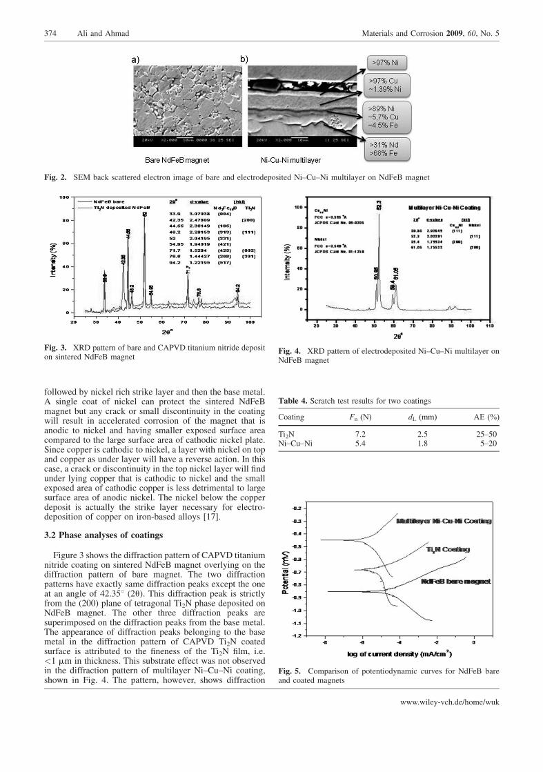
Figure 1 shows the microstructures of coated NdFeBmagnets. The CAPVD titanium nitride coating is very thin,only 0.7� 0.2 mm (Fig. 1a), while the overall thickness ofelectrodeposited multilayer coating is 17� 2 mm (Fig. 1b).Fine discontinuities were also observed in the titanium nit-ride coating. On the other hand, the multilayer coatingappears to be continuous providing complete coverage to thecomplex microstructure of the substrate consisting of threephases, i.e. Nd2Fe14B matrix phase, B-rich and Nd-rich grainboundary phases. Electrochemically, the grain boundaryphases are anodic to the matrix phase leading to acceleratedcorrosion at the grain boundaries owing to the small anodicarea connected to the large cathodic area [16]. This is why itis necessary to find proper protection for sintered NdFeBpermanent magnets in humid and other corrosive environ-ments. The microstructure of sintered NdFeB permanentmagnet is shown in Fig. 2a. Figure 2b shows the EDSanalyses of all the distinct layers in the electrodepositedNi–Cu–Ni multilayer coating. The top layer is almostcompletely nickel below which is a thicker copper rich layer
eB magnets, etched in 2% nital
374 Ali and Ahmad Materials and Corrosion 2009, 60, No. 5
Fig. 2. SEM back scattered electron image of bare and electrodeposited Ni–Cu–Ni multilayer on NdFeB magnet
Fig. 3. XRD pattern of bare and CAPVD titanium nitride depositon sintered NdFeB magnet
Fig. 4. XRD pattern of electrodeposited Ni–Cu–Ni multilayer onNdFeB magnet
Table 4. Scratch test results for two coatings
Coating Fn (N) dL (mm) AE (%)
Ti2N 7.2 2.5 25–50Ni–Cu–Ni 5.4 1.8 5–20
Fig. 5. Comparison of potentiodynamic curves for NdFeB bareand coated magnets
followed by nickel rich strike layer and then the base metal.A single coat of nickel can protect the sintered NdFeBmagnet but any crack or small discontinuity in the coatingwill result in accelerated corrosion of the magnet that isanodic to nickel and having smaller exposed surface areacompared to the large surface area of cathodic nickel plate.Since copper is cathodic to nickel, a layer with nickel on topand copper as under layer will have a reverse action. In thiscase, a crack or discontinuity in the top nickel layer will findunder lying copper that is cathodic to nickel and the smallexposed area of cathodic copper is less detrimental to largesurface area of anodic nickel. The nickel below the copperdeposit is actually the strike layer necessary for electro-deposition of copper on iron-based alloys [17].
3.2 Phase analyses of coatings
Figure 3 shows the diffraction pattern of CAPVD titaniumnitride coating on sintered NdFeB magnet overlying on thediffraction pattern of bare magnet. The two diffractionpatterns have exactly same diffraction peaks except the oneat an angle of 42.358 (2u). This diffraction peak is strictlyfrom the (200) plane of tetragonal Ti2N phase deposited onNdFeB magnet. The other three diffraction peaks aresuperimposed on the diffraction peaks from the base metal.The appearance of diffraction peaks belonging to the basemetal in the diffraction pattern of CAPVD Ti2N coatedsurface is attributed to the fineness of the Ti2N film, i.e.<1 mm in thickness. This substrate effect was not observedin the diffraction pattern of multilayer Ni–Cu–Ni coating,shown in Fig. 4. The pattern, however, shows diffraction
www.wiley-vch.de/home/wuk

Materials and Corrosion 2009, 60, No. 5 Corrosion protection of sintered NdFeB magnets by CAPVD Ti2N coating 375
Table 5. Data for electrochemical testing of bare and coated NdFeB magnets
Base metal Coating FCP (V) bc (V/decade) ba (V/decade) Corrosion rate (mpy)
NdFeB Bare metal �0.8514 0.1013 62.12� 10�3 9.066Ti2N �0.6816 0.5393 80.23� 10�3 4.009Ni–Cu–Ni �0.4485 0.2637 14.18� 10�2 1.121
Table 6. Magnetic properties of coated NdFeB magnets
Coating Br (Gauss) iHC (kOe) BHmax (MGOe)
Ti2N 1.39T 104 15.21 47.55Ni–Cu–Ni 1.30T 104 15.33 42.14
peaks from two phases, i.e. pure nickel and Cu3.8Ni. It can beinferred that the top layer is pure nickel whilethe Cu3.8Ni phase is present at the interface of electro-deposited copper and nickel layers. The pattern has nodiffraction peak belonging to the base metal mainly becausethe thickness of the coating is more than the penetrationdepth of X-rays used.
3.3 Coating strength
Table 4 summarizes the scratch test results for the twocoatings. The Ti2N coating, though less than 1 mm in thick-ness, withstood more normal force (Fn) compared to Ni–Cu–Ni coating and the indenter traversed more linear distance(dL) before it pierced through the coating and approached tothe base metal. The percentile range of AE is also more forthe titanium nitride coating. All these indicate that the overallstrength (wear and adhesion) of Ti2N coating is more than theNi–Cu–Ni coating.
3.4 Potentiodynamic polarization tests
Figure 5 shows the comparison of electrochemical potent-iodynamic polarization curves for bare and coated NdFeBmagnets and results are tabulated in Table 5. It is clear thatthe free corroding potential (FCP) of sintered NdFeBmagnets moves towards positive potentials by both Ti2N andNi–Cu–Ni coatings. The rate of corrosion has also decreasedsignificantly. The minimum corrosion rate in 3.5 wt% NaClsolution is for Ni–Cu–Ni coating. It is expected that byincreasing the film thickness the electrochemical propertiesof Ti2N coating can be improved. However, attempts forincreasing CAPVD Ti2N film thickness by increasingcoating time, nitrogen partial pressure and/or bias voltagehave not yet been successful.
(Received: August 14, 2008) W5132(Accepted: September 8, 2008)
3.5 Magnetic properties
The magnetic properties for both the coatings are givenin Table 6. Both titanium nitride and Ni–Cu–Ni coatingshave come up with similar magnetic characteristics for thesintered NdFeB permanent magnets. The slightly highervalues of remanance and BHmax may be attributed to the finefilm thickness of Ti2N coating. So there is no threat to themagnetic properties of sintered NdFeB permanent magnetsby CAPVD titanium nitride coating.
www.wiley-vch.de/home/wuk
4 Conclusions
The magnetic properties of CAPVD Ti2N coated NdFeBmagnets remain comparable to the electrodeposited Ni–Cu–Ni coating.
The CAPVD Ti2N coating improves the FCP andcorrosion rate of sintered NdFeB magnets in 3.5 wt% NaClsolution; however, multilayer Ni–Cu–Ni coating is moreeffective in this regard. The electrochemical properties of athicker Ti2N deposit are expected to come closer to theelectrodeposited Ni–Cu–Ni coating.
The overall strength of CAPVD Ti2N coating is more thanthe electrodeposited Ni–Cu–Ni multilayer coating.
5 References
[1] M. Sagawa, S. Fujimura, N. Togawa, H. Yamamoro,
Y. Matsura, J. Appl. Phys. 1984, 55, 2083.
[2] G. C. Hadjipanayis, R. C. Hazelton, K. R. Lawless, J. Appl.Phys. 1984, 55, 2073.
[3] J. J. Croat, J. F. Herbst, R. W. Lee, F. E. Pinkerton, J. Appl.Phys. 1984, 55, 2079.
[4] S. Constantinides, MRS Conference & Exposition, San
Fransisco, 1995.[5] H. Bala, G. Pawlowska, S. Szymura, Y. M. Rabinovich,
Br. Corros. J. 1998, 33, 37.
[6] C. W. Cheng, F. T. Cheng, J. Appl. Phys. 1998, 83, 6417.
[7] C. J. Willman, K. S. V. L. Narasimhan, J. Appl. Phys. 1987, 61,
3766.
[8] S. Hirosawa, S. Mino, H. Tomizawa, J. Appl. Phys. 1991, 70,
5844.
[9] K. Tokuhara, S. Hirosawa, J. Appl. Phys. 1991, 69, 5521.
[10] M. Sagawa, P. Tenaud, F. Vial, K. Hiraga, IEEE Trans. Magn.1990, 26, 1957.
[11] E. Rozendall, IEEE Trans. Magn. 1990, 26, 2631.
[12] S. M. Tamborim, D. S. Azambuja, A. M. Saliba Silva, I. Costa,
J. Surf. Coat. Technol. 2006, 200, 6826–6831.
[13] Yu. Shengxue, C. Ling, J. Rare Earths 2006, 24, 223–226.
[14] H. Zhang, Y. W. Song, Z. L. Song, J. Mater. Corros. 2008, 59,
324.
[15] Z. Iqbal, A. Rauf, A. Ali, A. ul Haq, A. Q. Khan, J. Vacuum1998, 51, 629.
[16] A. Gurrapa, J. Alloy Comp. 2003, 360, 236.
[17] L. M. Weisenberger, ASM Metal Handbook, 9th edition,
Vol 5, ASM International, Materials Park, OH, USA, 1990,p. 161.


![Simulation of NdFeB Permanent Magnets at Low Temperature · Figure 1: Evolution of NdFeB anisotropy constants with temperature [7]. In a permanent magnet, the overall magnetization](https://img.dokumen.tips/doc/110x75/5b915de509d3f210288b8285/simulation-of-ndfeb-permanent-magnets-at-low-temperature-figure-1-evolution.jpg)