Embed Size (px)
Citation preview
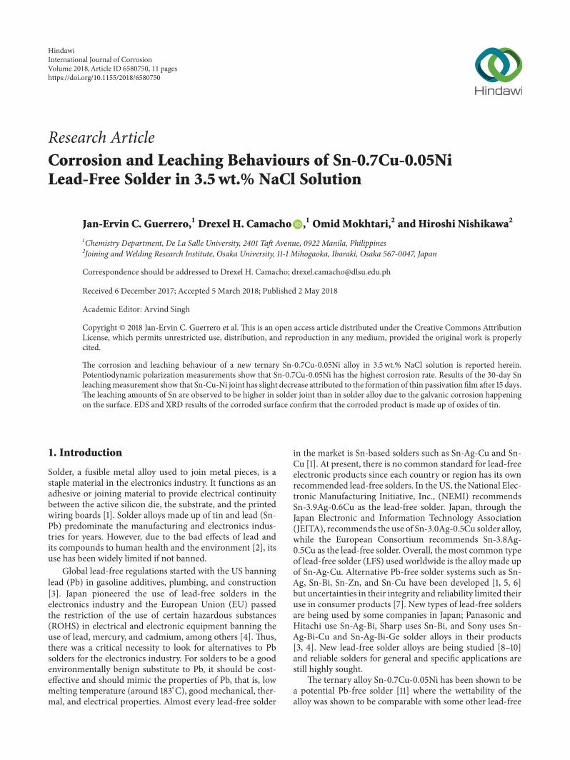
Research ArticleCorrosion and Leaching Behaviours of Sn-07Cu-005NiLead-Free Solder in 35wt NaCl Solution
Jan-Ervin C Guerrero1 Drexel H Camacho 1 OmidMokhtari2 and Hiroshi Nishikawa2
1Chemistry Department De La Salle University 2401 Taft Avenue 0922 Manila Philippines2Joining and Welding Research Institute Osaka University 11-1 Mihogaoka Ibaraki Osaka 567-0047 Japan
Correspondence should be addressed to Drexel H Camacho drexelcamachodlsueduph
Received 6 December 2017 Accepted 5 March 2018 Published 2 May 2018
Academic Editor Arvind Singh
Copyright copy 2018 Jan-Ervin C Guerrero et al This is an open access article distributed under the Creative Commons AttributionLicense which permits unrestricted use distribution and reproduction in any medium provided the original work is properlycited
The corrosion and leaching behaviour of a new ternary Sn-07Cu-005Ni alloy in 35 wt NaCl solution is reported hereinPotentiodynamic polarization measurements show that Sn-07Cu-005Ni has the highest corrosion rate Results of the 30-day Snleachingmeasurement show that Sn-Cu-Ni joint has slight decrease attributed to the formation of thin passivation film after 15 daysThe leaching amounts of Sn are observed to be higher in solder joint than in solder alloy due to the galvanic corrosion happeningon the surface EDS and XRD results of the corroded surface confirm that the corroded product is made up of oxides of tin
1 Introduction
Solder a fusible metal alloy used to join metal pieces is astaple material in the electronics industry It functions as anadhesive or joining material to provide electrical continuitybetween the active silicon die the substrate and the printedwiring boards [1] Solder alloys made up of tin and lead (Sn-Pb) predominate the manufacturing and electronics indus-tries for years However due to the bad effects of lead andits compounds to human health and the environment [2] itsuse has been widely limited if not banned
Global lead-free regulations started with the US banninglead (Pb) in gasoline additives plumbing and construction[3] Japan pioneered the use of lead-free solders in theelectronics industry and the European Union (EU) passedthe restriction of the use of certain hazardous substances(ROHS) in electrical and electronic equipment banning theuse of lead mercury and cadmium among others [4] Thusthere was a critical necessity to look for alternatives to Pbsolders for the electronics industry For solders to be a goodenvironmentally benign substitute to Pb it should be cost-effective and should mimic the properties of Pb that is lowmelting temperature (around 183∘C) good mechanical ther-mal and electrical properties Almost every lead-free solder
in the market is Sn-based solders such as Sn-Ag-Cu and Sn-Cu [1] At present there is no common standard for lead-freeelectronic products since each country or region has its ownrecommended lead-free solders In theUS theNational Elec-tronic Manufacturing Initiative Inc (NEMI) recommendsSn-39Ag-06Cu as the lead-free solder Japan through theJapan Electronic and Information Technology Association(JEITA) recommends the use of Sn-30Ag-05Cu solder alloywhile the European Consortium recommends Sn-38Ag-05Cu as the lead-free solder Overall the most common typeof lead-free solder (LFS) used worldwide is the alloy made upof Sn-Ag-Cu Alternative Pb-free solder systems such as Sn-Ag Sn-Bi Sn-Zn and Sn-Cu have been developed [1 5 6]but uncertainties in their integrity and reliability limited theiruse in consumer products [7] New types of lead-free soldersare being used by some companies in Japan Panasonic andHitachi use Sn-Ag-Bi Sharp uses Sn-Bi and Sony uses Sn-Ag-Bi-Cu and Sn-Ag-Bi-Ge solder alloys in their products[3 4] New lead-free solder alloys are being studied [8ndash10]and reliable solders for general and specific applications arestill highly sought
The ternary alloy Sn-07Cu-005Ni has been shown to bea potential Pb-free solder [11] where the wettability of thealloy was shown to be comparable with some other lead-free
HindawiInternational Journal of CorrosionVolume 2018 Article ID 6580750 11 pageshttpsdoiorg10115520186580750
2 International Journal of Corrosion
Epoxy Resin
Metal of Interest
(a)
Copper Wire
Polymer Insulation
Epoxy Resin
Metal of Interest
(b)
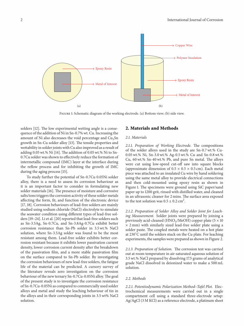
Figure 1 Schematic diagram of the working electrode (a) Bottom view (b) side view
solders [12] The low experimental wetting angle is a conse-quence of the addition ofNi in Sn-07wt Cu Increasing theamount of Ni also decreases the void percentage and Cu3Sngrowth in Sn-Cu solder alloy [13] The tensile properties andwettability in solder joints withCu also improved as a result ofadding 005wt Ni [14] The addition of 005wt Ni to Sn-07Cu solder was shown to effectively reduce the formation ofintermetallic compound (IMC) layer at the interface duringthe reflow process and for inhibiting the growth of IMCduring the aging process [15]
To study further the potential of Sn-07Cu 005Ni solderalloy there is a need to assess its corrosion behaviour asit is an important factor to consider in formulating newsolder materials [16] The presence of moisture and corrosivesaltsions triggers the corrosion activity of these soldermetalsaffecting the form fit and function of the electronic device[17 18] Corrosion behaviours of lead-free solders are mainlystudied using sodium chloride (NaCl) electrolyte to simulatethe seawater condition using different types of lead-free sol-ders [19ndash24] Li et al [20] reported that lead-free solders suchas Sn-35Ag Sn-07Cu and Sn-38Ag-07Cu exhibit bettercorrosion resistance than Sn-Pb solder in 35 wt NaClsolution where Sn-35Ag solder was found to be the mostresistant among them Lead-free solder exhibits better cor-rosion resistant because it exhibits lower passivation currentdensity lower corrosion current density after the breakdownof the passivation film and a more stable passivation filmon the surface compared to Sn-Pb solder By investigatingthe corrosion behaviours of new lead-free solders the fatiguelife of the material can be predicted A cursory survey ofthe literature reveals zero investigation on the corrosionbehaviour of the new ternary Sn-07Cu-005Ni alloyThe goalof the present study is to investigate the corrosion resistanceof Sn-07Cu-005Ni as compared to commercially used solderalloys and metal and study the leaching behaviour of tin inthe alloys and in their corresponding joints in 35 wt NaClsolution
2 Materials and Methods
21 Materials
211 Preparation of Working Electrode The compositionsof the solder alloys used in the study are Sn-07 wt Cu-005wt Ni Sn-30 wt Ag-05 wt Cu and Sn-08 wtCu 60wt Sn-40wt Pb and pure Sn metal The alloyswere cut using low-speed cut-off saw into square blocks(approximate dimension of 05 times 05 times 05 cm) Each metalpiece was attached to an insulated Cu wire by hand solderingusing the same metal alloy to provide electrical connectionsand then cold-mounted using epoxy resin as shown inFigure 1 The specimens were ground using SiC papersandpaper up to 1200 grit rinsed with distilled water and cleanedin an ultrasonic cleaner for 2mins The surface area exposedto the test solution was 05 plusmn 02 cm2
212 Preparation of Solder Alloy and Solder Joint for Leach-ing Measurement Solder joints were prepared by joining apreviously acid-cleaned (HNO3MeOH) copper plate (5 times 10times 2mm) with similarly sized lead-free solder plate using asolder paste The coupled metals were heated on a hot plateat 230∘C until the solders stuck on the Cu plate For leachingexperiments the samples were prepared as shown in Figure 2
213 Preparation of Solution The corrosion test was carriedout at room temperature in air-saturated aqueous solution of35 wt NaCl prepared by dissolving 175 grams of analyticalgrade NaCl dissolved in deionized water to make a 500mLsolution
22 Methods
221 Potentiodynamic Polarization MethodndashTafel Plot Elec-trochemical measurements were carried out in a singlecompartment cell using a standard three-electrode setupAgAgCl (3M KCl) as a reference electrode a platinum sheet
International Journal of Corrosion 3
Pasteur PipettePasteur Pipette
Acrylic bonding agent Acrylic bonding agent
Lead-solder Lead-solderCu-plate
Solder alloy Solder joint
01 mm20 mm
Figure 2 Preparation of samples for leaching measurements
(064 cm2) as a counter electrode and the lead-free soldersas the working electrode All the measurements were doneunder N2 conditions Metrohm Autolab PGSTAT 128N wasused as an electrochemical interface to control and record thepotential The samples were immersed in 250mL corrosivemedium inside the cell at room temperature for 180 s toattain a steady-state potential or open circuit potential (OCP)Potentiodynamic polarization curves were determined atminus1500 to 500mV range distinctive for the lead-free solderused on the study at an ASTM scan rate of 100mVs steppotential is at 045mV and is presented in the form of typicalpolarization curves log 119868 versus voltage From the Tafel plotthe corrosion current (119868CORR) corrosion potential (119864CORR)polarization resistance (119877119901) and corrosion rate (CR) of themetal alloys were calculated using the corrosion rate Tafelslope method (Autolab application note COR02)
222 Leaching Measurements For the leachingdissolutionmeasurement the method by Cheng et al [25] was adoptedwith slight modification Small test cells containing 15mLof test solutions were placed in a temperature-controlledoil bath at 45 plusmn 3∘C Every 3 days oxygen was injectedinto the test solutions by gas flowmeter with a flow rateof 46mLmin for 5mins to keep the solution under lowsaturation of oxygen Two mL of fresh test solutions wasadded to the test cell every 7 days or when the solution isreduced to keep the solution at 15mL The testing periodswere done for 7 15 and 30 days After immersion for thesubscribed period 15mL was taken and diluted into a 25mLvolumetric flask with deionized water If there exists someprecipitation in the test solution sodium phosphate solutionwas used to dissolve the precipitatesThe concentration of Snin the diluted solutionwas analyzed usingAtomicAbsorptionSpectrophotometer (Shimadzu AA-6300 Atomic AbsorptionSpectrophotometer) and the leaching amount per surfacearea of each element in the solders and their joints werecalculated
223 Surface Morphology and Elemental Analysis The cor-roded surfaces of the samples were investigated using field-emission scanning electron microscopies (FESEM) (JEOLJSM-5310) and SEM (JEOL JSM-6500F) both equipped
Sn-Cu-NiSn-Ag-CuSn-Cu
Sn-PbSn metal
minus12
minus10
minus8
minus6
minus4
minus2
005minus25 0minus05minus1minus2 minus15
E (V) versus AgAgCl
log(i)
(Ac
m2)
Figure 3 Potentiodynamic polarization curves of Sn and solderalloys in 35 wt NaCl solution under N2 atmosphere Scan rangefrom minus1500 to 500mV scan rate 100mVs step potential 045mV
with an energy dispersive X-ray spectroscopy (EDS) X-ray diffraction (XRD) measurements were performed with adiffractometer (Rigaku Ultima IV) using Cu-K120572 radiation (120582= 15405 A) at an accelerating voltage of 40 kVThe diffractedbeam was scanned in steps of 002∘ across a 2120579 range of20ndash90∘
3 Results and Discussion
31 Potentiodynamic PolarizationMethodndashTafel Plot TheSn-07CuNi005 (referred to herein as Sn-Cu-Ni) in 35 wtNaCl solution showed a Tafel plot positioned at (119864corr)minus078mV versus AgAgCl (Figure 3) As compared to Sn-30Ag-05Cu (referred to herein as Sn-Ag-Cu) and Sn-08Cu(referred to herein as Sn-Cu) alloys there is an observedshift of corrosion potential 119864corr of lead-free solders to aless negative value following the sequence Sn-Cu-Ni lt Sn-Cu lt Sn-Ag-Cu During the anodic polarization processa stable passivation film is formed on the surface of themetal alloys (vide infra) This passivation film determines thecorrosion behaviour of the solder in the given media Theshift to a less negative potential signifies a formation of amore stable passivation film [26] which protects the soldersand increases their corrosion resistance The polarizationresistance (119877119901) data (Table 1) showed that Sn-Pb solder hasthe highest119877119901 (805250KΩ) and lowest corrosion rate (01949times 10minus2mmyr) compared to the lead-free solders Between thethree lead-free solder alloys Sn-Cu-Ni showed the highestcorrosion rate and Sn-Ag-Cu showed the lowest corrosionrate in 35 wt NaCl solution
311 Microstructure Characterization of the Lead-Free Sol-ders The microstructure of solders before potentiodynamicpolarization (Figure 4(a)) is a smooth surface showing thepolishing lines and EDS analysis confirms the elemental
4 International Journal of Corrosion
Table 1 Summary of corrosion parameters of metal alloys in 35 wt NaCl solution
Sample 119864corr(V) versus AgAgCl
119868corr(120583Acm2)
119877119901(kΩ)
CR(mmyr) times 10minus2
Sn-Cu-Ni minus078 898 1494 487Sn-Ag-Cu minus073 306 4386 171Sn-Cu minus075 391 2826 207Sn-Pb minus079 039 80525 019Sn minus059 055 40602 023119864corr corrosion potential 119868corr corrosion current density 119877119901 polarization resistance and CR corrosion rate
Table 2 Surface element concentration of different solders before potentiodynamic polarization in 35 wt NaCl solution
Surface element composition (atom)Sn Ag Cu Ni Pb
Sn-Cu-Ni 9859 - 127 014 -Sn-Ag-Cu 9674 274 052 - -Sn-Cu 9897 - 138 - -Sn-Pb 5903 - - - 4097Sn 10000 - - - -
Sn-A
g-Cu
Sn-C
u-N
iSn
-Cu-
Ni
Sn-P
bSn
met
al
Before After
(A)
(B)
(A)
(a)
(B)
(b) (c)
Figure 4 The microstructure of the metal surfaces on differentsolders before (a) after (b) and distinct morphologies on specifiedpoints (c) after potentiodynamic polarization tests in 35 wt NaClsolution
composition of each solder (Table 2) After potentiodynamicpolarization in 35 wt NaCl solution (Figure 4(b)) themicrostructure of corroded Sn-Cu-Ni alloy had a porousflake-like surface while the Sn-Ag-Cu and Sn-Cu soldersshowed fibrous network oriented randomly on the surface inagreement with the observations of Li et al [20] Notable isthe flake-like microstructures in Sn-Cu-Ni which is similarin some respect to the Sn-Pb alloy The EDS analysis onthe surface of the corroded samples on each specified pointwas determined (Figure 4(c) and Table 3) and revealed thepresence of Sn O and Cl indicating that the corrosionproducts are composed of the oxides and chlorides oftin In conventional electrochemical reaction Sn acts asan anode and reacts with Clminus from the medium to formSnCl2 which results in pitting and severed dissolution of Sn[27]
The cross-section of the metals after potentiodynamicpolarization (Figure 5) showed visible corrosion layers dis-tinct from the bulk metal EDS analysis of the cross-sectionarea (Table 4) for both lead and lead-free solders showedthe top layer having similar corrosion products composedof Sn-rich and O-rich areas with lt1 Cl The Sn-Pb soldershowed an outer layer rich in O while the inner layer wasrich in Sn The formation of oxides on the surface of theSn-Pb solder indicates the presence of a stable passivationfilm that protects the metal from corroding This explainswhy Sn-Pb solder has a better corrosion resistance thanlead-free solders In the case of the lead-free solders sincethey have a different composition than Sn-Pb the thinlayer of oxides that formed on the surface of the alloy isnot enough to protect the metal from the electrochemicalprocess
International Journal of Corrosion 5
Table 3 Surface element concentration of different solders after potentiodynamic polarization in 35 wt NaCl solution on specific pointsas indicated in Figure 4(c)
Surface element concentration (atom)Sn Ag Cu Pb Ni Cl O
Sn-Cu-Ni (A) 2040 - 190 - - 350 7420Sn-Cu-Ni (B) 5670 - 080 - - 020 4230Sn-Ag-Cu (A) 2360 - - - - 870 6770Sn-Ag-Cu (B) 3230 - 020 - - 1210 5540Sn-Cu 2050 - 010 - - 1070 6870Sn-Pb 2840 - - - - 060 7100Sn 2990 - - - - 1500 5510
(a)
Solder layer
Corrosion layer
(b)
(c) (d) (e)
Figure 5 Cross-section image of the solders after potentiodynamic polarization test in 35 wt NaCl solution (a) Sn (b) Sn-Pb (c) Sn-Ag-Cu (d) Sn-Cu-Ni (e) Sn-Cu
312 Phase Composition Analysis of Corrosion Product onthe Surface of the Solder Sample The XRD diffractograms ofcorrosion products (Figure 6) showed corresponding XRDpeaks attributed to tin oxides (SnO and SnO2) and somechlorides When compared with the XRD results of Yanand Xian [28] peaks for tin hydroxide (Sn(OH2)) were alsoobserved particularly for Sn-Pb and Sn metal [25] Theseoxides effectively protect the metal The oxides howeverwere not visibly detected in Pb-free solders indicating nil orminimal formation of the passivation layer
During potentiodynamic polarizationmeasurements thereduction of oxygen in the neutral aqueous solution (1)initially occurs [20]
4eminus +O2 + 2H2O 997888rarr 4OHminus (1)
Once the current reaches 10mAcm2 bubbles were observedfrom the solution caused by the evolution of hydrogen fromthe cathode
2H2O + 2eminus 997888rarr H2 + 2OH
minus (2)
The following plausible anodic reactions would occur [17 19]
Sn 997888rarr Sn2+ + 2eminus (3)
Sn2+ 997888rarr Sn4+ + 2eminus (4)
Sn + 2OHminus minus 2eminus 997888rarr Sn (OH)2 (5)
Sn + 2OHminus minus 2eminus 997888rarr SnO +H2O (6)
2Sn +O2 + 6H2O 997888rarr 2Sn (OH)2 (7)
Sn (OH)2 + 2OHminus minus 2eminus 997888rarr Sn (OH)4 (8)
2Sn2+ + 6H2O +O2 997888rarr 2Sn (OH)4 + 4H+ (9)
Formation of tin oxides is thermodynamically favourablethus tin hydroxides can dehydrate easily to form SnO andSnO2 [25 29] Although not detected in XRD due to its traceconcentration relative to Sn the potential corrosion products
6 International Journal of Corrosion
Table 4 Cross-section element concentration of different solders after Potentiodynamic polarization tests in 35 wt NaCl solution
Cross-section element concentration (atom)Sn Ag Cu Ni Pb Cl O
Sn-Cu-NiTop layer 6399 - 060 022 - 092 3391Inner layer 9859 - 127 014 - - -
Sn-Ag-CuTop layer 4095 112 017 - - 015 5727Inner layer 9736 201 063 - - - -
Sn-CuTop layer 6458 - 072 - - 060 3335Inner layer 9930 - 070 - - - -
Sn-PbTop layer 685 - - - 391 091 8803Inner layer 6016 - - - 3984 - -
SnTop layer 3262 - - - - 037 6641Inner layer 9985 - - - - 015 -
Sn-Ag-Cu alloy
Cl
Ag2 Sn
Ag4 Sn
Cu4 O
2
9050 7030102 (deg)
020406080
100120140
Inte
nsity
Sn-Cu-Ni alloy
30 50 70 90102 (deg)
0
200
400
600
800
1000
Inte
nsity
Sn-Pb solder
Cl
SnCl2
40 60 80202 (deg)
0
50
100
150
200
250
Inte
nsity
Sn-Cu alloy
Cl
40 60 80202 (deg)
0
100
200
300
400
Inte
nsity
Sn metal
30 50 70 90102 (deg)
0
100
200
300
400
500
Inte
nsity
SnSnOSnO2
Sn(OH)2
Figure 6 XRD patterns of surface product on different solder material after potentiodynamic polarization test
International Journal of Corrosion 7
of copper and nickel aremetal chlorides Corrosion of copperis dependent on the presence of chloride ions either throughdirect formation of cupric chloride
Cularrrarr Cu+ + eminus (10)
Cu+ + 2Clminus larrrarr CuCl2minus (11)
or through the electro-dissolution of copper [30]
Cu + Clminus larrrarr CuCl + eminus (12)
CuCl + Clminus larrrarr CuCl2minus (13)
The anodic polarization of copper alloys in NaCl solutionlowers the fracture stresses as measured in slow strain exper-iments making copper alloys under cyclic stresses to havelower service lives in chloride solutions [31] Thus chloridespenetrate into the material crevices allowing for corrosionof susceptible atoms such as copper to occur For nickelcorrosion the initial step is nickel hydration to facilitatedissolution and this can occur when water transport into thematerial is enhanced The transport of water is dependenton chloride environment This was observed when we com-pared the potentiodynamic polarization of Sn-Cu-Ni alloy inneutral chloride-containingmedium (119864corr =minus0776V versusAgAgCl 119868corr = 8982 120583Acm2) and in acidic chloride-freeelectrolyte (01M HNO3 119864corr = minus0356V versus AgAgCl119868corr = 434 120583Acm2) A sudden shift of corrosion potential toa less negative value is observed attributed to the formationof the passivation film The absence of chloride in HNO3medium promotes barrier creation preventing hydration andcorrosion to occurThis suggests that Sn-Cu-Ni alloy has highcorrosion resistance in an acidic chloride-free environmentChlorides even in small amounts can break the protectivefilms initiating the occurrence of corrosion
32 Soldering Properties and LeachingMeasurements Duringthe preparation of the solder joints with copper substrates abetter surface finish of the joints was observed when Sn-Cu-Ni solder was used compared to Sn-Cu alloys The design ofadding Ni to common Sn-Cu alloy improved the solderingproperty [32] These observations were consistent with theunique morphology of the intermetallic compound (IMC)layer reported by Harcuba et al [33] The IMC was describedas noncompact islands of solder entrapped in the IMC phaseand that the IMC layer contains more Ni than the solderNickel addition promoted the significant acceleration of thegrowth kinetics of the IMC layer
The solder joints and the raw Pb-free solder alloys weresubjected to corrosive media immersion to determine theleaching behaviour (Figure 7) The amount of Sn leachedcorrelates with the corrosion rate of the alloys [25 29 34]Since the results of potentiodynamic polarization test showedthat all of the three Pb-free solders had higher corrosion ratethan the Sn-Pb solder and Sn metal leaching amounts of Snwere done only for the Pb-free soldersThe leaching amountsof Sn after immersion in 35 wt NaCl solution after 30 daysare observed to be greater for solder joints compared to itscorresponding alloy Sn-Ag-Cu alloy had the highest leaching
Sn-Cu-Ni Sn-Ag-Cu Sn-Cu
Leac
hing
amou
nts o
f Sn
(mg
L)
35 NaCl solution 30th day
alloyjoint
0
2000
4000
6000
8000
10000
12000
14000
Figure 7 Atomic Absorption Spectroscopy (AAS) results on Tin(Sn) leaching from lead-free solder alloy and joint after 30 days
5 10 15 20 25 30 350(Days)
0
2000
4000
6000
8000
10000
12000
14000Le
achi
ng am
ount
of S
n (m
gcm
2)
Sn-Cu-Ni jointSn-Ag-Cu jointSn-Cu joint
Sn-Cu-Ni alloySn-Ag-Cu alloySn-Cu alloy
Figure 8 Leaching kinetics of Sn from Sn-Ag-Cu Sn-Cu-Ni andSn-Cu alloy and their joints in 35 wt NaCl solution
of Sn for the solder alloys followed by Sn-Cu alloy while Sn-Cu-Ni had the lowest leaching amount after 30 days Forsolder joints leached Sn follows the order Sn-Cu gt Sn-Ag-Cugt Sn-Cu-Ni
Leaching kinetics of Sn from the metals (Figure 8) showthat solder joints gave a higher amount of leached Sncompared to their alloy counterpartsThe use of Cu-substratein the solder joint setup affects the leaching behaviour of SnThis is because dissimilar metals having different oxidationpotentials in contact with each other experience galvanic cor-rosion [25 29] which does not occur in solder alloys aloneAccording to Lao et al [29] the current density of the solderjoint is almost twofold higher than its corresponding solderalloy Thus the galvanic cell (anode = Sn cathode = Cu)accelerates the leaching amount of Sn from the joint
8 International Journal of Corrosion
O
Ni
Cu
NiCuNa
Cl
ClSn
Sn
Sn
Sn
Sn
Sn
NiCuNi
Cu
O 1586 Na 655 Cl 430 Cu 067 Sn 7262
0
500
1000
1500
Cou
nts
5 10 15 200Energy (keV)
0
20
40
60
80
Element ()
(a)
O
CuCu
Na
ClCl
Sn
Sn
Sn
Sn
Sn
Sn
CuCu
O 2648 Na 098 Cl 074 Cu 068 Sn 7112
0
500
1000
1500C
ount
s
5 10 15 200Energy (keV)
0
20
40
60
80
Element ()
(b)
Figure 9 Surface morphology analysis of Sn-Cu-Ni (a) solder alloy and (b) solder joint and their corresponding EDS spectra after 30-dayleaching measurements in 35 wt NaCl solution
The microstructure analysis of Sn-Ni-Cu solder after30-day immersion in NaCl solution (Figure 9) showed amore corroded surface for the joint and microstructure iscomposed of platelet-like materials on the surface EDSanalysis on the surface showed high amounts of Sn andO suggesting that the corrosion products are composedprimarily of oxides of Sn and small amounts of chloridesThis is further confirmed by the detection of XRD patternsspecific to SnO2 (Figure 10) Similarly corresponding peaksfor Sn(OH)2 were detected from Yan and Xian [28]
321 Microstructure of Corrosion Products on Solder SurfaceThemicrostructures of the corrosion surface were monitoredas the exposure to the corrosive media increases Generallyas the alloy (Figure 11) was exposed to the salt solutionthe surface changed dramatically from smooth to porouswith the formation of plate-like structures attributed to theweakly bonded corrosion products that form on the surfaceThese compounds which have been identified in EDS andXRD as oxides of tin are typical corrosion products Theformation of these compounds is a result of a charge transferreaction between Sn metal salt ion atmospheric O2 andH2O during anodic polarization following the mechanismproposed by Mohran et al [35] These corrosion products
are weakly held by the bulk metal and can easily chip-offinto the solution in agreement with the leaching experimentsThe microstructural changes that can be observed for Sn-Cu-Ni are the noticeable degree of high corrosion product(platelet-like structure) after 7-day exposure compared to Sn-Ag-Cu and Sn-Cu The corrosion products are formed alongthe cracks which allow the water to seep-in triggering thecorrosion reaction As the exposure time increases the entiresurface was covered with corrosion products
For the solder joints the microstructure changes werelikewise monitored (Figure 12) A more dramatic morphol-ogy can be observed characterized by branched crystallitessponge-like structure networked branches and platelet-likematerials The formation of these microstructures occurswithin 7-day exposure and increases gradually as timeincreases This is the consequence of galvanic reaction thatoccurs since the solder joints are in contact with the Cumetal as substrate The galvanic reaction triggers the veryfast corrosion process The EDS analysis of these microstruc-tures reveals O and Sn-rich surface indicating oxides of Snformation which was further confirmed by XRD as SnO2(Figure 10)
Generally the surfaces of the alloys show some corrosionproduct as evidenced by the plate-like structuresThe surfaces
International Journal of Corrosion 9
Sn-Cu-Ni alloymdash15 days
0
200
400
600
800
Inte
nsity
40 60 80202 (deg)
Sn-Cu-Ni jointmdash15 days
0
50
100
150
200
250
Inte
nsity
40 60 80202 (deg)
Sn-Ag-Cu jointmdash15 days
0
50
100
150
200
250
300
Inte
nsity
40 60 80202 (deg)
Sn-Ag-Cu alloymdash15 days
0
100
200
300
400
500
600
Inte
nsity
40 60 80202 (deg)
Sn-Cu alloymdash15 days
40 60 80202 (deg)
0
100
200
300
400
500
Inte
nsity
SnSnO2
Sn(OH)2
SnSnO2
Sn(OH)2
Sn-Cu jointmdash15 days
40 60 80202 (deg)
0
5000
10000
15000
20000
25000
30000
Inte
nsity
Figure 10 XRD patterns of surface product of Sn-Ag-Cu Sn-Cu-Ni and Sn-Cu solder alloy and joint after 15-day immersion in 35 wtNaCl solution
are covered by a small degree of corrosion layer suggestingminimal corrosion on the alloy surface However the surfaceof the joint showed a high degree of corrosion with the entiresurface covered with corrosion products forming nanocrys-tals and sponges Similar morphology was reported by Laoet al [29] in the leaching measurement of Sn-075Cu solderalloy and joint in simulated soil solutionsThe corrosion layerformed on the surface of the alloy forms a protecting filmthat has a shielding effect on the Sn ion transport betweenthe solder and the solution However in the case of the solderjoint the loosely bound corrosion layer can break-off easilyThe corrosion products that made up the surface would nolonger protect the substrate resulting in plenty of leachingamounts of Sn coming from the solder joint
The result of potentiodynamic polarization and leachingtests in 35 wt NaCl solution is conflicting Results forthe Tafel extrapolation show that Sn-Cu-Ni has the highest
corrosion rate while the 30-day immersion of the solderalloy and joint in NaCl solution showed the lowest amountof leached Sn for all the solders understudied This wasattributed to the rapid analysis in an electrochemical processwhere corrosion is forcedly induced on the surface of themetal by applying voltage A rapid measurement can influ-ence the formation of the passivation film on the surface ofthe metal On the other hand the long exposure time withthe corrosive media in leaching experiments allows an actualelectrochemical process to occur andmeasured progressivelyIn these conditions the formation of corrosion product isgradual and there is longer timeframe for the stabilization andformation of the passivation film
These results are significant since in electronic processesthe solder alloy is not used alone Rather it is used in contactwith other metals mostly Cu in most electronic substratesThese lead-free solders therefore once in a corrosive media
10 International Journal of Corrosion
Sn-Ag-Cu alloy Sn-Cu-Ni alloy Sn-Cu alloy
0-da
y7-
days
15-d
ays
30-d
ays
Figure 11 SEM image of lead-free solder alloy after 7 15 and 30 daysleaching measurement in 35 wt NaCl solution
Sn-Ag-Cu joint Sn-Cu-Ni joint Sn-Cu joint
0-da
y7-
days
15-d
ays
30-d
ays
Figure 12 SEM image of lead-free solder joint after 7 15 and 30 daysleaching measurement in 35 wt NaCl solution
such as aqueous NaCl atmosphere are prone to corrosioneven within 7 days of exposure The corrosion reaction istriggered by the galvanic reaction that occurs when this hap-pens inside an electronic gadget The interconnections andelectrical connectivity are lost affecting the form featuresand function of the device
4 Conclusions
The corrosion behaviour of Sn-Cu-Ni lead-free solder wasdescribed for the first time In 35 wt NaCl environment
potentiodynamic polarization test revealed that the new Sn-Cu-Ni solder has higher corrosion rate compared to Sn-Cuand Sn-Ag-Cu However longer exposure of the Sn-Cu-Nialloy and joint to the corrosive medium for up to 30 daysshowed the lowest leaching rate of Sn compared to Sn-Cuand Sn-Ag-Cu solders Generally alloys have lower leachingrate compared to the corresponding joint due to the galvanicreaction occurring in the joint setup For chloride-containingsolution the corrosion and leaching behaviour of Sn-Ag-Cuis better compared to Sn-Ni-Cu and Sn-Cu Further studyis underway in acidic and basic media and will be reportedelsewhere
Conflicts of Interest
There are no conflicts of interest related to this paper
Acknowledgments
This work was supported by the Accelerated Scienceand Technology Human Resource Development Program(ASTHRDP) of the Department of Science and TechnologyScience Education Institute (DOST-SEI) Jan-Ervin C Guer-rero is grateful for the Japan Sakura Science Program
References
[1] M Abtew and G Selvaduray ldquoLead-free solders in micro-electronicsrdquo Materials Science and Engineering A StructuralMaterials Properties Microstructure and Processing vol 27 no5 pp 95ndash141 2000
[2] S Tong Y von Schirnding and T Prapamontol ldquoEnviron-mental lead exposure a public health problem of globaldimensionsrdquo Bulletin of the World Health Organization 2000httpwwwwhointbulletinarchives78(9)1068pdf
[3] J H Lau and K Liu ldquoGlobal Trends in Lead-free solderingrdquoInternational Journal of Advanced Packaging Technology vol 13no 2 pp 25ndash28 2004
[4] S Garesan andM Pecht Lead Free Electronics IEEE PressJohnWiley amp Sons Inc Hoboken NJ USA 2006
[5] K Suganuma ldquoAdvances in lead-free electronics solderingrdquoCurrent Opinion in Solid State amp Materials Science vol 5 no1 pp 55ndash64 2001
[6] N Chawla ldquoThermomechanical behaviour of environmentallybenign Pb-free soldersrdquo InternationalMaterials Reviews vol 54no 6 pp 368ndash384 2009
[7] K Zeng and K N Tu ldquoSix cases of reliability study of Pb-free solder joints in electronic packaging technologyrdquoMaterialsScience and Engineering Reports vol 38 no 2 pp 55ndash106 2002
[8] D K Mu S D McDonald J Read H Huang and K NogitaldquoCritical properties of Cu6Sn5 in electronic devices recentprogress and a reviewrdquo Current Opinion in Solid State ampMaterials Science vol 20 no 2 pp 55ndash76 2016
[9] H R Kotadia P D Howes and S H Mannan ldquoA review onthe development of low melting temperature Pb-free soldersrdquoMicroelectronics Reliability vol 54 no 6-7 pp 1253ndash1273 2014
[10] G Zeng S McDonald and K Nogita ldquoDevelopment of high-temperature solders reviewrdquoMicroelectronics Reliability vol 52no 7 pp 1306ndash1322 2012
International Journal of Corrosion 11
[11] H Nishikawa J Y Piao and T Takemoto ldquoEffect of Niaddition on interfacial reaction between Sn-Cu solder and Cubase metalrdquo in Joining of Advanced and Specialty MaterialsVII Proceedings from Materials Solutions 2004 on Joining ofAdvanced and Specialty Materials T J Lienert Ed vol 35 pp208ndash211 Columbus OH USA October 2006
[12] B L Silva N Cheung A Garcia and J E Spinelli ldquoEvaluationof soldersubstrate thermal conductance and wetting angle ofSnndash07 wtCundash(0ndash01 wtNi) solder alloysrdquo Materials Lettersvol 142 pp 163ndash167 2015
[13] J-W Yoon B-I Noh B-K Kim C-C Shur and S-B JungldquoWettability and interfacial reactions of Sn-Ag-CuCu and Sn-Ag-NiCu solder jointsrdquo Journal of Alloys and Compounds vol486 no 1-2 pp 142ndash147 2009
[14] L Yang J Ge Y Zhang J Dai H Liu and J Xiang ldquoInves-tigation on the Microstructure Interfacial IMC Layer andMechanical Properties of CuSn-07Cu-xNiCu Solder JointsrdquoJournal of Electronic Materials vol 45 no 7 pp 3766ndash37752016
[15] H Nishikawa J Y Piao and T Takemoto ldquoInterfacial reactionbetween Sn-07Cu (-Ni) solder and Cu substraterdquo Journal ofElectronic Materials vol 35 no 5 pp 1127ndash1132 2006
[16] S Farina and C Morando ldquoComparative corrosion behaviourof different Sn-based solder alloysrdquo Journal of Materials ScienceMaterials in Electronics vol 26 no 1 pp 464ndash471 2014
[17] K Pietrzak M Grobelny K Makowska et al ldquoStructuralaspects of the behavior of lead-free solder in the corrosive solu-tionrdquo Journal of Materials Engineering and Performance vol 21no 5 pp 648ndash654 2012
[18] M Reid and L F Garfias-Mesias ldquoCorrosion of electronicslead-free initiativesrdquo in Uhligrsquos Corrosion Handbook R WRevie Ed pp 565ndash570 John Wiley amp Sons Inc Hoboken NJUSA 3rd edition 2011
[19] K-L Lin and T-P Liu ldquoThe electrochemical corrosion behav-iour of Pb-free Al-Zn-Sn solders in NaCl solutionrdquo MaterialsChemistry and Physics vol 56 no 2 pp 171ndash176 1998
[20] D Li P P Conway and C Liu ldquoCorrosion characterizationof tin-lead and lead free solders in 35 wt NaCl solutionrdquoCorrosion Science vol 50 no 4 pp 995ndash1004 2008
[21] W R Osorio E S Freitas J E Spinelli and A GarcialdquoElectrochemical behavior of a lead-free Sn-Cu solder alloy inNaCl solutionrdquo Corrosion Science vol 80 pp 71ndash81 2014
[22] M Liu W Yang Y Ma C Tang H Tang and Y Zhan ldquoTheelectrochemical corrosion behavior of Pb-free Sn-85Zn-XCrsolders in 35 wt NaCl solutionrdquo Materials Chemistry andPhysics vol 168 pp 27ndash34 2015
[23] A Kamarul Asri and E Hamzah ldquoCorrosion behaviour of lead-free and Sn-Pb solders in 35wt NaClrdquo Advanced MaterialsResearch vol 686 pp 250ndash260 2013
[24] U S Mohanty and K-L Lin ldquoElectrochemical corrosionbehaviour of Pb-free Sn-85Zn-005Al-XGa and Sn-3Ag-05Cualloys in chloride containing aqueous solutionrdquo CorrosionScience vol 50 no 9 pp 2437ndash2443 2008
[25] C Q Cheng F Yang J Zhao L HWang and X G Li ldquoLeach-ing of heavy metal elements in solder alloysrdquo Corrosion Sciencevol 53 no 5 pp 1738ndash1747 2011
[26] A Wierzbicka-Miernik J Guspiel and L Zabdyr ldquoCorrosionbehavior of lead-free SAC-type solder alloys in liquid mediardquoArchives of Civil and Mechanical Engineering vol 15 no 1 pp206ndash213 2015
[27] A Sharma S Das and K Das ldquoElectrochemical corrosionbehavior of CeO2 nanoparticle reinforced Sn-Ag based leadfree nanocomposite solders in 35wt NaCl bathrdquo Surface andCoatings Technology vol 261 pp 235ndash243 2015
[28] Z Yan andA-P Xian ldquoCorrosion of Ga-doped Sn-07Cu solderin simulated marine atmosphererdquo Metallurgical and MaterialsTransactions A Physical Metallurgy and Materials Science vol44 no 3 pp 1462ndash1474 2013
[29] X-D Lao C-Q Cheng X-H Min et al ldquoCorrosion andleaching behaviors of Sn-based alloy in simulated soil solutionsrdquoTransactions of Nonferrous Metals Society of China vol 26 no2 pp 581ndash588 2016
[30] F Arjmand and A Adriaens ldquoInfluence of pH and chlorideconcentration on the corrosion behavior of unalloyed copperin NaCl solution a comparative study between the micro andmacro scalesrdquoMaterials vol 5 no 12 pp 2439ndash2464 2012
[31] B D Craig and D S Anderson Eds Handbook of CorrosionData ASM International Materials Park OH USA 2nd edi-tion 1995
[32] T Ventura C M Gourlay K Nogita T Nishimura M Rappazand A K Dahle ldquoThe influence of 0-01 wt Ni on the micro-structure and fluidity length of Sn-07Cu-xNirdquo Journal ofElectronic Materials vol 37 no 1 pp 32ndash39 2008
[33] P Harcuba M Janecek and M Slamova ldquoThe effect of Cu andNi on the structure and properties of the IMC formed by thereaction of liquid Sn-Cu based solders with Cu substraterdquo inProceedings of Contributed Papers (WDS rsquo08) part III pp 220ndash224 Prague Czech June 2008
[34] M Mori K Miura T Sasaki and T Ohtsuka ldquoCorrosion of tinalloys in sulfuric and nitric acidsrdquoCorrosion Science vol 44 no4 pp 887ndash898 2002
[35] H SMohran A-R El-Sayed andHMAbdEl-Lateef ldquoAnodicbehavior of tin indium and tin-indium alloys in oxalic acidsolutionrdquo Journal of Solid State Electrochemistry vol 13 no 8pp 1279ndash1290 2009
CorrosionInternational Journal of
Hindawiwwwhindawicom Volume 2018
Advances in
Materials Science and EngineeringHindawiwwwhindawicom Volume 2018
Hindawiwwwhindawicom Volume 2018
Journal of
Chemistry
Analytical ChemistryInternational Journal of
Hindawiwwwhindawicom Volume 2018
ScienticaHindawiwwwhindawicom Volume 2018
Polymer ScienceInternational Journal of
Hindawiwwwhindawicom Volume 2018
Hindawiwwwhindawicom Volume 2018
Advances in Condensed Matter Physics
Hindawiwwwhindawicom Volume 2018
International Journal of
BiomaterialsHindawiwwwhindawicom
Journal ofEngineeringVolume 2018
Applied ChemistryJournal of
Hindawiwwwhindawicom Volume 2018
NanotechnologyHindawiwwwhindawicom Volume 2018
Journal of
Hindawiwwwhindawicom Volume 2018
High Energy PhysicsAdvances in
Hindawi Publishing Corporation httpwwwhindawicom Volume 2013Hindawiwwwhindawicom
The Scientific World Journal
Volume 2018
TribologyAdvances in
Hindawiwwwhindawicom Volume 2018
Hindawiwwwhindawicom Volume 2018
ChemistryAdvances in
Hindawiwwwhindawicom Volume 2018
Advances inPhysical Chemistry
Hindawiwwwhindawicom Volume 2018
BioMed Research InternationalMaterials
Journal of
Hindawiwwwhindawicom Volume 2018
Na
nom
ate
ria
ls
Hindawiwwwhindawicom Volume 2018
Journal ofNanomaterials
Submit your manuscripts atwwwhindawicom
2 International Journal of Corrosion
Epoxy Resin
Metal of Interest
(a)
Copper Wire
Polymer Insulation
Epoxy Resin
Metal of Interest
(b)
Figure 1 Schematic diagram of the working electrode (a) Bottom view (b) side view
solders [12] The low experimental wetting angle is a conse-quence of the addition ofNi in Sn-07wt Cu Increasing theamount of Ni also decreases the void percentage and Cu3Sngrowth in Sn-Cu solder alloy [13] The tensile properties andwettability in solder joints withCu also improved as a result ofadding 005wt Ni [14] The addition of 005wt Ni to Sn-07Cu solder was shown to effectively reduce the formation ofintermetallic compound (IMC) layer at the interface duringthe reflow process and for inhibiting the growth of IMCduring the aging process [15]
To study further the potential of Sn-07Cu 005Ni solderalloy there is a need to assess its corrosion behaviour asit is an important factor to consider in formulating newsolder materials [16] The presence of moisture and corrosivesaltsions triggers the corrosion activity of these soldermetalsaffecting the form fit and function of the electronic device[17 18] Corrosion behaviours of lead-free solders are mainlystudied using sodium chloride (NaCl) electrolyte to simulatethe seawater condition using different types of lead-free sol-ders [19ndash24] Li et al [20] reported that lead-free solders suchas Sn-35Ag Sn-07Cu and Sn-38Ag-07Cu exhibit bettercorrosion resistance than Sn-Pb solder in 35 wt NaClsolution where Sn-35Ag solder was found to be the mostresistant among them Lead-free solder exhibits better cor-rosion resistant because it exhibits lower passivation currentdensity lower corrosion current density after the breakdownof the passivation film and a more stable passivation filmon the surface compared to Sn-Pb solder By investigatingthe corrosion behaviours of new lead-free solders the fatiguelife of the material can be predicted A cursory survey ofthe literature reveals zero investigation on the corrosionbehaviour of the new ternary Sn-07Cu-005Ni alloyThe goalof the present study is to investigate the corrosion resistanceof Sn-07Cu-005Ni as compared to commercially used solderalloys and metal and study the leaching behaviour of tin inthe alloys and in their corresponding joints in 35 wt NaClsolution
2 Materials and Methods
21 Materials
211 Preparation of Working Electrode The compositionsof the solder alloys used in the study are Sn-07 wt Cu-005wt Ni Sn-30 wt Ag-05 wt Cu and Sn-08 wtCu 60wt Sn-40wt Pb and pure Sn metal The alloyswere cut using low-speed cut-off saw into square blocks(approximate dimension of 05 times 05 times 05 cm) Each metalpiece was attached to an insulated Cu wire by hand solderingusing the same metal alloy to provide electrical connectionsand then cold-mounted using epoxy resin as shown inFigure 1 The specimens were ground using SiC papersandpaper up to 1200 grit rinsed with distilled water and cleanedin an ultrasonic cleaner for 2mins The surface area exposedto the test solution was 05 plusmn 02 cm2
212 Preparation of Solder Alloy and Solder Joint for Leach-ing Measurement Solder joints were prepared by joining apreviously acid-cleaned (HNO3MeOH) copper plate (5 times 10times 2mm) with similarly sized lead-free solder plate using asolder paste The coupled metals were heated on a hot plateat 230∘C until the solders stuck on the Cu plate For leachingexperiments the samples were prepared as shown in Figure 2
213 Preparation of Solution The corrosion test was carriedout at room temperature in air-saturated aqueous solution of35 wt NaCl prepared by dissolving 175 grams of analyticalgrade NaCl dissolved in deionized water to make a 500mLsolution
22 Methods
221 Potentiodynamic Polarization MethodndashTafel Plot Elec-trochemical measurements were carried out in a singlecompartment cell using a standard three-electrode setupAgAgCl (3M KCl) as a reference electrode a platinum sheet
International Journal of Corrosion 3
Pasteur PipettePasteur Pipette
Acrylic bonding agent Acrylic bonding agent
Lead-solder Lead-solderCu-plate
Solder alloy Solder joint
01 mm20 mm
Figure 2 Preparation of samples for leaching measurements
(064 cm2) as a counter electrode and the lead-free soldersas the working electrode All the measurements were doneunder N2 conditions Metrohm Autolab PGSTAT 128N wasused as an electrochemical interface to control and record thepotential The samples were immersed in 250mL corrosivemedium inside the cell at room temperature for 180 s toattain a steady-state potential or open circuit potential (OCP)Potentiodynamic polarization curves were determined atminus1500 to 500mV range distinctive for the lead-free solderused on the study at an ASTM scan rate of 100mVs steppotential is at 045mV and is presented in the form of typicalpolarization curves log 119868 versus voltage From the Tafel plotthe corrosion current (119868CORR) corrosion potential (119864CORR)polarization resistance (119877119901) and corrosion rate (CR) of themetal alloys were calculated using the corrosion rate Tafelslope method (Autolab application note COR02)
222 Leaching Measurements For the leachingdissolutionmeasurement the method by Cheng et al [25] was adoptedwith slight modification Small test cells containing 15mLof test solutions were placed in a temperature-controlledoil bath at 45 plusmn 3∘C Every 3 days oxygen was injectedinto the test solutions by gas flowmeter with a flow rateof 46mLmin for 5mins to keep the solution under lowsaturation of oxygen Two mL of fresh test solutions wasadded to the test cell every 7 days or when the solution isreduced to keep the solution at 15mL The testing periodswere done for 7 15 and 30 days After immersion for thesubscribed period 15mL was taken and diluted into a 25mLvolumetric flask with deionized water If there exists someprecipitation in the test solution sodium phosphate solutionwas used to dissolve the precipitatesThe concentration of Snin the diluted solutionwas analyzed usingAtomicAbsorptionSpectrophotometer (Shimadzu AA-6300 Atomic AbsorptionSpectrophotometer) and the leaching amount per surfacearea of each element in the solders and their joints werecalculated
223 Surface Morphology and Elemental Analysis The cor-roded surfaces of the samples were investigated using field-emission scanning electron microscopies (FESEM) (JEOLJSM-5310) and SEM (JEOL JSM-6500F) both equipped
Sn-Cu-NiSn-Ag-CuSn-Cu
Sn-PbSn metal
minus12
minus10
minus8
minus6
minus4
minus2
005minus25 0minus05minus1minus2 minus15
E (V) versus AgAgCl
log(i)
(Ac
m2)
Figure 3 Potentiodynamic polarization curves of Sn and solderalloys in 35 wt NaCl solution under N2 atmosphere Scan rangefrom minus1500 to 500mV scan rate 100mVs step potential 045mV
with an energy dispersive X-ray spectroscopy (EDS) X-ray diffraction (XRD) measurements were performed with adiffractometer (Rigaku Ultima IV) using Cu-K120572 radiation (120582= 15405 A) at an accelerating voltage of 40 kVThe diffractedbeam was scanned in steps of 002∘ across a 2120579 range of20ndash90∘
3 Results and Discussion
31 Potentiodynamic PolarizationMethodndashTafel Plot TheSn-07CuNi005 (referred to herein as Sn-Cu-Ni) in 35 wtNaCl solution showed a Tafel plot positioned at (119864corr)minus078mV versus AgAgCl (Figure 3) As compared to Sn-30Ag-05Cu (referred to herein as Sn-Ag-Cu) and Sn-08Cu(referred to herein as Sn-Cu) alloys there is an observedshift of corrosion potential 119864corr of lead-free solders to aless negative value following the sequence Sn-Cu-Ni lt Sn-Cu lt Sn-Ag-Cu During the anodic polarization processa stable passivation film is formed on the surface of themetal alloys (vide infra) This passivation film determines thecorrosion behaviour of the solder in the given media Theshift to a less negative potential signifies a formation of amore stable passivation film [26] which protects the soldersand increases their corrosion resistance The polarizationresistance (119877119901) data (Table 1) showed that Sn-Pb solder hasthe highest119877119901 (805250KΩ) and lowest corrosion rate (01949times 10minus2mmyr) compared to the lead-free solders Between thethree lead-free solder alloys Sn-Cu-Ni showed the highestcorrosion rate and Sn-Ag-Cu showed the lowest corrosionrate in 35 wt NaCl solution
311 Microstructure Characterization of the Lead-Free Sol-ders The microstructure of solders before potentiodynamicpolarization (Figure 4(a)) is a smooth surface showing thepolishing lines and EDS analysis confirms the elemental
4 International Journal of Corrosion
Table 1 Summary of corrosion parameters of metal alloys in 35 wt NaCl solution
Sample 119864corr(V) versus AgAgCl
119868corr(120583Acm2)
119877119901(kΩ)
CR(mmyr) times 10minus2
Sn-Cu-Ni minus078 898 1494 487Sn-Ag-Cu minus073 306 4386 171Sn-Cu minus075 391 2826 207Sn-Pb minus079 039 80525 019Sn minus059 055 40602 023119864corr corrosion potential 119868corr corrosion current density 119877119901 polarization resistance and CR corrosion rate
Table 2 Surface element concentration of different solders before potentiodynamic polarization in 35 wt NaCl solution
Surface element composition (atom)Sn Ag Cu Ni Pb
Sn-Cu-Ni 9859 - 127 014 -Sn-Ag-Cu 9674 274 052 - -Sn-Cu 9897 - 138 - -Sn-Pb 5903 - - - 4097Sn 10000 - - - -
Sn-A
g-Cu
Sn-C
u-N
iSn
-Cu-
Ni
Sn-P
bSn
met
al
Before After
(A)
(B)
(A)
(a)
(B)
(b) (c)
Figure 4 The microstructure of the metal surfaces on differentsolders before (a) after (b) and distinct morphologies on specifiedpoints (c) after potentiodynamic polarization tests in 35 wt NaClsolution
composition of each solder (Table 2) After potentiodynamicpolarization in 35 wt NaCl solution (Figure 4(b)) themicrostructure of corroded Sn-Cu-Ni alloy had a porousflake-like surface while the Sn-Ag-Cu and Sn-Cu soldersshowed fibrous network oriented randomly on the surface inagreement with the observations of Li et al [20] Notable isthe flake-like microstructures in Sn-Cu-Ni which is similarin some respect to the Sn-Pb alloy The EDS analysis onthe surface of the corroded samples on each specified pointwas determined (Figure 4(c) and Table 3) and revealed thepresence of Sn O and Cl indicating that the corrosionproducts are composed of the oxides and chlorides oftin In conventional electrochemical reaction Sn acts asan anode and reacts with Clminus from the medium to formSnCl2 which results in pitting and severed dissolution of Sn[27]
The cross-section of the metals after potentiodynamicpolarization (Figure 5) showed visible corrosion layers dis-tinct from the bulk metal EDS analysis of the cross-sectionarea (Table 4) for both lead and lead-free solders showedthe top layer having similar corrosion products composedof Sn-rich and O-rich areas with lt1 Cl The Sn-Pb soldershowed an outer layer rich in O while the inner layer wasrich in Sn The formation of oxides on the surface of theSn-Pb solder indicates the presence of a stable passivationfilm that protects the metal from corroding This explainswhy Sn-Pb solder has a better corrosion resistance thanlead-free solders In the case of the lead-free solders sincethey have a different composition than Sn-Pb the thinlayer of oxides that formed on the surface of the alloy isnot enough to protect the metal from the electrochemicalprocess
International Journal of Corrosion 5
Table 3 Surface element concentration of different solders after potentiodynamic polarization in 35 wt NaCl solution on specific pointsas indicated in Figure 4(c)
Surface element concentration (atom)Sn Ag Cu Pb Ni Cl O
Sn-Cu-Ni (A) 2040 - 190 - - 350 7420Sn-Cu-Ni (B) 5670 - 080 - - 020 4230Sn-Ag-Cu (A) 2360 - - - - 870 6770Sn-Ag-Cu (B) 3230 - 020 - - 1210 5540Sn-Cu 2050 - 010 - - 1070 6870Sn-Pb 2840 - - - - 060 7100Sn 2990 - - - - 1500 5510
(a)
Solder layer
Corrosion layer
(b)
(c) (d) (e)
Figure 5 Cross-section image of the solders after potentiodynamic polarization test in 35 wt NaCl solution (a) Sn (b) Sn-Pb (c) Sn-Ag-Cu (d) Sn-Cu-Ni (e) Sn-Cu
312 Phase Composition Analysis of Corrosion Product onthe Surface of the Solder Sample The XRD diffractograms ofcorrosion products (Figure 6) showed corresponding XRDpeaks attributed to tin oxides (SnO and SnO2) and somechlorides When compared with the XRD results of Yanand Xian [28] peaks for tin hydroxide (Sn(OH2)) were alsoobserved particularly for Sn-Pb and Sn metal [25] Theseoxides effectively protect the metal The oxides howeverwere not visibly detected in Pb-free solders indicating nil orminimal formation of the passivation layer
During potentiodynamic polarizationmeasurements thereduction of oxygen in the neutral aqueous solution (1)initially occurs [20]
4eminus +O2 + 2H2O 997888rarr 4OHminus (1)
Once the current reaches 10mAcm2 bubbles were observedfrom the solution caused by the evolution of hydrogen fromthe cathode
2H2O + 2eminus 997888rarr H2 + 2OH
minus (2)
The following plausible anodic reactions would occur [17 19]
Sn 997888rarr Sn2+ + 2eminus (3)
Sn2+ 997888rarr Sn4+ + 2eminus (4)
Sn + 2OHminus minus 2eminus 997888rarr Sn (OH)2 (5)
Sn + 2OHminus minus 2eminus 997888rarr SnO +H2O (6)
2Sn +O2 + 6H2O 997888rarr 2Sn (OH)2 (7)
Sn (OH)2 + 2OHminus minus 2eminus 997888rarr Sn (OH)4 (8)
2Sn2+ + 6H2O +O2 997888rarr 2Sn (OH)4 + 4H+ (9)
Formation of tin oxides is thermodynamically favourablethus tin hydroxides can dehydrate easily to form SnO andSnO2 [25 29] Although not detected in XRD due to its traceconcentration relative to Sn the potential corrosion products
6 International Journal of Corrosion
Table 4 Cross-section element concentration of different solders after Potentiodynamic polarization tests in 35 wt NaCl solution
Cross-section element concentration (atom)Sn Ag Cu Ni Pb Cl O
Sn-Cu-NiTop layer 6399 - 060 022 - 092 3391Inner layer 9859 - 127 014 - - -
Sn-Ag-CuTop layer 4095 112 017 - - 015 5727Inner layer 9736 201 063 - - - -
Sn-CuTop layer 6458 - 072 - - 060 3335Inner layer 9930 - 070 - - - -
Sn-PbTop layer 685 - - - 391 091 8803Inner layer 6016 - - - 3984 - -
SnTop layer 3262 - - - - 037 6641Inner layer 9985 - - - - 015 -
Sn-Ag-Cu alloy
Cl
Ag2 Sn
Ag4 Sn
Cu4 O
2
9050 7030102 (deg)
020406080
100120140
Inte
nsity
Sn-Cu-Ni alloy
30 50 70 90102 (deg)
0
200
400
600
800
1000
Inte
nsity
Sn-Pb solder
Cl
SnCl2
40 60 80202 (deg)
0
50
100
150
200
250
Inte
nsity
Sn-Cu alloy
Cl
40 60 80202 (deg)
0
100
200
300
400
Inte
nsity
Sn metal
30 50 70 90102 (deg)
0
100
200
300
400
500
Inte
nsity
SnSnOSnO2
Sn(OH)2
Figure 6 XRD patterns of surface product on different solder material after potentiodynamic polarization test
International Journal of Corrosion 7
of copper and nickel aremetal chlorides Corrosion of copperis dependent on the presence of chloride ions either throughdirect formation of cupric chloride
Cularrrarr Cu+ + eminus (10)
Cu+ + 2Clminus larrrarr CuCl2minus (11)
or through the electro-dissolution of copper [30]
Cu + Clminus larrrarr CuCl + eminus (12)
CuCl + Clminus larrrarr CuCl2minus (13)
The anodic polarization of copper alloys in NaCl solutionlowers the fracture stresses as measured in slow strain exper-iments making copper alloys under cyclic stresses to havelower service lives in chloride solutions [31] Thus chloridespenetrate into the material crevices allowing for corrosionof susceptible atoms such as copper to occur For nickelcorrosion the initial step is nickel hydration to facilitatedissolution and this can occur when water transport into thematerial is enhanced The transport of water is dependenton chloride environment This was observed when we com-pared the potentiodynamic polarization of Sn-Cu-Ni alloy inneutral chloride-containingmedium (119864corr =minus0776V versusAgAgCl 119868corr = 8982 120583Acm2) and in acidic chloride-freeelectrolyte (01M HNO3 119864corr = minus0356V versus AgAgCl119868corr = 434 120583Acm2) A sudden shift of corrosion potential toa less negative value is observed attributed to the formationof the passivation film The absence of chloride in HNO3medium promotes barrier creation preventing hydration andcorrosion to occurThis suggests that Sn-Cu-Ni alloy has highcorrosion resistance in an acidic chloride-free environmentChlorides even in small amounts can break the protectivefilms initiating the occurrence of corrosion
32 Soldering Properties and LeachingMeasurements Duringthe preparation of the solder joints with copper substrates abetter surface finish of the joints was observed when Sn-Cu-Ni solder was used compared to Sn-Cu alloys The design ofadding Ni to common Sn-Cu alloy improved the solderingproperty [32] These observations were consistent with theunique morphology of the intermetallic compound (IMC)layer reported by Harcuba et al [33] The IMC was describedas noncompact islands of solder entrapped in the IMC phaseand that the IMC layer contains more Ni than the solderNickel addition promoted the significant acceleration of thegrowth kinetics of the IMC layer
The solder joints and the raw Pb-free solder alloys weresubjected to corrosive media immersion to determine theleaching behaviour (Figure 7) The amount of Sn leachedcorrelates with the corrosion rate of the alloys [25 29 34]Since the results of potentiodynamic polarization test showedthat all of the three Pb-free solders had higher corrosion ratethan the Sn-Pb solder and Sn metal leaching amounts of Snwere done only for the Pb-free soldersThe leaching amountsof Sn after immersion in 35 wt NaCl solution after 30 daysare observed to be greater for solder joints compared to itscorresponding alloy Sn-Ag-Cu alloy had the highest leaching
Sn-Cu-Ni Sn-Ag-Cu Sn-Cu
Leac
hing
amou
nts o
f Sn
(mg
L)
35 NaCl solution 30th day
alloyjoint
0
2000
4000
6000
8000
10000
12000
14000
Figure 7 Atomic Absorption Spectroscopy (AAS) results on Tin(Sn) leaching from lead-free solder alloy and joint after 30 days
5 10 15 20 25 30 350(Days)
0
2000
4000
6000
8000
10000
12000
14000Le
achi
ng am
ount
of S
n (m
gcm
2)
Sn-Cu-Ni jointSn-Ag-Cu jointSn-Cu joint
Sn-Cu-Ni alloySn-Ag-Cu alloySn-Cu alloy
Figure 8 Leaching kinetics of Sn from Sn-Ag-Cu Sn-Cu-Ni andSn-Cu alloy and their joints in 35 wt NaCl solution
of Sn for the solder alloys followed by Sn-Cu alloy while Sn-Cu-Ni had the lowest leaching amount after 30 days Forsolder joints leached Sn follows the order Sn-Cu gt Sn-Ag-Cugt Sn-Cu-Ni
Leaching kinetics of Sn from the metals (Figure 8) showthat solder joints gave a higher amount of leached Sncompared to their alloy counterpartsThe use of Cu-substratein the solder joint setup affects the leaching behaviour of SnThis is because dissimilar metals having different oxidationpotentials in contact with each other experience galvanic cor-rosion [25 29] which does not occur in solder alloys aloneAccording to Lao et al [29] the current density of the solderjoint is almost twofold higher than its corresponding solderalloy Thus the galvanic cell (anode = Sn cathode = Cu)accelerates the leaching amount of Sn from the joint
8 International Journal of Corrosion
O
Ni
Cu
NiCuNa
Cl
ClSn
Sn
Sn
Sn
Sn
Sn
NiCuNi
Cu
O 1586 Na 655 Cl 430 Cu 067 Sn 7262
0
500
1000
1500
Cou
nts
5 10 15 200Energy (keV)
0
20
40
60
80
Element ()
(a)
O
CuCu
Na
ClCl
Sn
Sn
Sn
Sn
Sn
Sn
CuCu
O 2648 Na 098 Cl 074 Cu 068 Sn 7112
0
500
1000
1500C
ount
s
5 10 15 200Energy (keV)
0
20
40
60
80
Element ()
(b)
Figure 9 Surface morphology analysis of Sn-Cu-Ni (a) solder alloy and (b) solder joint and their corresponding EDS spectra after 30-dayleaching measurements in 35 wt NaCl solution
The microstructure analysis of Sn-Ni-Cu solder after30-day immersion in NaCl solution (Figure 9) showed amore corroded surface for the joint and microstructure iscomposed of platelet-like materials on the surface EDSanalysis on the surface showed high amounts of Sn andO suggesting that the corrosion products are composedprimarily of oxides of Sn and small amounts of chloridesThis is further confirmed by the detection of XRD patternsspecific to SnO2 (Figure 10) Similarly corresponding peaksfor Sn(OH)2 were detected from Yan and Xian [28]
321 Microstructure of Corrosion Products on Solder SurfaceThemicrostructures of the corrosion surface were monitoredas the exposure to the corrosive media increases Generallyas the alloy (Figure 11) was exposed to the salt solutionthe surface changed dramatically from smooth to porouswith the formation of plate-like structures attributed to theweakly bonded corrosion products that form on the surfaceThese compounds which have been identified in EDS andXRD as oxides of tin are typical corrosion products Theformation of these compounds is a result of a charge transferreaction between Sn metal salt ion atmospheric O2 andH2O during anodic polarization following the mechanismproposed by Mohran et al [35] These corrosion products
are weakly held by the bulk metal and can easily chip-offinto the solution in agreement with the leaching experimentsThe microstructural changes that can be observed for Sn-Cu-Ni are the noticeable degree of high corrosion product(platelet-like structure) after 7-day exposure compared to Sn-Ag-Cu and Sn-Cu The corrosion products are formed alongthe cracks which allow the water to seep-in triggering thecorrosion reaction As the exposure time increases the entiresurface was covered with corrosion products
For the solder joints the microstructure changes werelikewise monitored (Figure 12) A more dramatic morphol-ogy can be observed characterized by branched crystallitessponge-like structure networked branches and platelet-likematerials The formation of these microstructures occurswithin 7-day exposure and increases gradually as timeincreases This is the consequence of galvanic reaction thatoccurs since the solder joints are in contact with the Cumetal as substrate The galvanic reaction triggers the veryfast corrosion process The EDS analysis of these microstruc-tures reveals O and Sn-rich surface indicating oxides of Snformation which was further confirmed by XRD as SnO2(Figure 10)
Generally the surfaces of the alloys show some corrosionproduct as evidenced by the plate-like structuresThe surfaces
International Journal of Corrosion 9
Sn-Cu-Ni alloymdash15 days
0
200
400
600
800
Inte
nsity
40 60 80202 (deg)
Sn-Cu-Ni jointmdash15 days
0
50
100
150
200
250
Inte
nsity
40 60 80202 (deg)
Sn-Ag-Cu jointmdash15 days
0
50
100
150
200
250
300
Inte
nsity
40 60 80202 (deg)
Sn-Ag-Cu alloymdash15 days
0
100
200
300
400
500
600
Inte
nsity
40 60 80202 (deg)
Sn-Cu alloymdash15 days
40 60 80202 (deg)
0
100
200
300
400
500
Inte
nsity
SnSnO2
Sn(OH)2
SnSnO2
Sn(OH)2
Sn-Cu jointmdash15 days
40 60 80202 (deg)
0
5000
10000
15000
20000
25000
30000
Inte
nsity
Figure 10 XRD patterns of surface product of Sn-Ag-Cu Sn-Cu-Ni and Sn-Cu solder alloy and joint after 15-day immersion in 35 wtNaCl solution
are covered by a small degree of corrosion layer suggestingminimal corrosion on the alloy surface However the surfaceof the joint showed a high degree of corrosion with the entiresurface covered with corrosion products forming nanocrys-tals and sponges Similar morphology was reported by Laoet al [29] in the leaching measurement of Sn-075Cu solderalloy and joint in simulated soil solutionsThe corrosion layerformed on the surface of the alloy forms a protecting filmthat has a shielding effect on the Sn ion transport betweenthe solder and the solution However in the case of the solderjoint the loosely bound corrosion layer can break-off easilyThe corrosion products that made up the surface would nolonger protect the substrate resulting in plenty of leachingamounts of Sn coming from the solder joint
The result of potentiodynamic polarization and leachingtests in 35 wt NaCl solution is conflicting Results forthe Tafel extrapolation show that Sn-Cu-Ni has the highest
corrosion rate while the 30-day immersion of the solderalloy and joint in NaCl solution showed the lowest amountof leached Sn for all the solders understudied This wasattributed to the rapid analysis in an electrochemical processwhere corrosion is forcedly induced on the surface of themetal by applying voltage A rapid measurement can influ-ence the formation of the passivation film on the surface ofthe metal On the other hand the long exposure time withthe corrosive media in leaching experiments allows an actualelectrochemical process to occur andmeasured progressivelyIn these conditions the formation of corrosion product isgradual and there is longer timeframe for the stabilization andformation of the passivation film
These results are significant since in electronic processesthe solder alloy is not used alone Rather it is used in contactwith other metals mostly Cu in most electronic substratesThese lead-free solders therefore once in a corrosive media
10 International Journal of Corrosion
Sn-Ag-Cu alloy Sn-Cu-Ni alloy Sn-Cu alloy
0-da
y7-
days
15-d
ays
30-d
ays
Figure 11 SEM image of lead-free solder alloy after 7 15 and 30 daysleaching measurement in 35 wt NaCl solution
Sn-Ag-Cu joint Sn-Cu-Ni joint Sn-Cu joint
0-da
y7-
days
15-d
ays
30-d
ays
Figure 12 SEM image of lead-free solder joint after 7 15 and 30 daysleaching measurement in 35 wt NaCl solution
such as aqueous NaCl atmosphere are prone to corrosioneven within 7 days of exposure The corrosion reaction istriggered by the galvanic reaction that occurs when this hap-pens inside an electronic gadget The interconnections andelectrical connectivity are lost affecting the form featuresand function of the device
4 Conclusions
The corrosion behaviour of Sn-Cu-Ni lead-free solder wasdescribed for the first time In 35 wt NaCl environment
potentiodynamic polarization test revealed that the new Sn-Cu-Ni solder has higher corrosion rate compared to Sn-Cuand Sn-Ag-Cu However longer exposure of the Sn-Cu-Nialloy and joint to the corrosive medium for up to 30 daysshowed the lowest leaching rate of Sn compared to Sn-Cuand Sn-Ag-Cu solders Generally alloys have lower leachingrate compared to the corresponding joint due to the galvanicreaction occurring in the joint setup For chloride-containingsolution the corrosion and leaching behaviour of Sn-Ag-Cuis better compared to Sn-Ni-Cu and Sn-Cu Further studyis underway in acidic and basic media and will be reportedelsewhere
Conflicts of Interest
There are no conflicts of interest related to this paper
Acknowledgments
This work was supported by the Accelerated Scienceand Technology Human Resource Development Program(ASTHRDP) of the Department of Science and TechnologyScience Education Institute (DOST-SEI) Jan-Ervin C Guer-rero is grateful for the Japan Sakura Science Program
References
[1] M Abtew and G Selvaduray ldquoLead-free solders in micro-electronicsrdquo Materials Science and Engineering A StructuralMaterials Properties Microstructure and Processing vol 27 no5 pp 95ndash141 2000
[2] S Tong Y von Schirnding and T Prapamontol ldquoEnviron-mental lead exposure a public health problem of globaldimensionsrdquo Bulletin of the World Health Organization 2000httpwwwwhointbulletinarchives78(9)1068pdf
[3] J H Lau and K Liu ldquoGlobal Trends in Lead-free solderingrdquoInternational Journal of Advanced Packaging Technology vol 13no 2 pp 25ndash28 2004
[4] S Garesan andM Pecht Lead Free Electronics IEEE PressJohnWiley amp Sons Inc Hoboken NJ USA 2006
[5] K Suganuma ldquoAdvances in lead-free electronics solderingrdquoCurrent Opinion in Solid State amp Materials Science vol 5 no1 pp 55ndash64 2001
[6] N Chawla ldquoThermomechanical behaviour of environmentallybenign Pb-free soldersrdquo InternationalMaterials Reviews vol 54no 6 pp 368ndash384 2009
[7] K Zeng and K N Tu ldquoSix cases of reliability study of Pb-free solder joints in electronic packaging technologyrdquoMaterialsScience and Engineering Reports vol 38 no 2 pp 55ndash106 2002
[8] D K Mu S D McDonald J Read H Huang and K NogitaldquoCritical properties of Cu6Sn5 in electronic devices recentprogress and a reviewrdquo Current Opinion in Solid State ampMaterials Science vol 20 no 2 pp 55ndash76 2016
[9] H R Kotadia P D Howes and S H Mannan ldquoA review onthe development of low melting temperature Pb-free soldersrdquoMicroelectronics Reliability vol 54 no 6-7 pp 1253ndash1273 2014
[10] G Zeng S McDonald and K Nogita ldquoDevelopment of high-temperature solders reviewrdquoMicroelectronics Reliability vol 52no 7 pp 1306ndash1322 2012
International Journal of Corrosion 11
[11] H Nishikawa J Y Piao and T Takemoto ldquoEffect of Niaddition on interfacial reaction between Sn-Cu solder and Cubase metalrdquo in Joining of Advanced and Specialty MaterialsVII Proceedings from Materials Solutions 2004 on Joining ofAdvanced and Specialty Materials T J Lienert Ed vol 35 pp208ndash211 Columbus OH USA October 2006
[12] B L Silva N Cheung A Garcia and J E Spinelli ldquoEvaluationof soldersubstrate thermal conductance and wetting angle ofSnndash07 wtCundash(0ndash01 wtNi) solder alloysrdquo Materials Lettersvol 142 pp 163ndash167 2015
[13] J-W Yoon B-I Noh B-K Kim C-C Shur and S-B JungldquoWettability and interfacial reactions of Sn-Ag-CuCu and Sn-Ag-NiCu solder jointsrdquo Journal of Alloys and Compounds vol486 no 1-2 pp 142ndash147 2009
[14] L Yang J Ge Y Zhang J Dai H Liu and J Xiang ldquoInves-tigation on the Microstructure Interfacial IMC Layer andMechanical Properties of CuSn-07Cu-xNiCu Solder JointsrdquoJournal of Electronic Materials vol 45 no 7 pp 3766ndash37752016
[15] H Nishikawa J Y Piao and T Takemoto ldquoInterfacial reactionbetween Sn-07Cu (-Ni) solder and Cu substraterdquo Journal ofElectronic Materials vol 35 no 5 pp 1127ndash1132 2006
[16] S Farina and C Morando ldquoComparative corrosion behaviourof different Sn-based solder alloysrdquo Journal of Materials ScienceMaterials in Electronics vol 26 no 1 pp 464ndash471 2014
[17] K Pietrzak M Grobelny K Makowska et al ldquoStructuralaspects of the behavior of lead-free solder in the corrosive solu-tionrdquo Journal of Materials Engineering and Performance vol 21no 5 pp 648ndash654 2012
[18] M Reid and L F Garfias-Mesias ldquoCorrosion of electronicslead-free initiativesrdquo in Uhligrsquos Corrosion Handbook R WRevie Ed pp 565ndash570 John Wiley amp Sons Inc Hoboken NJUSA 3rd edition 2011
[19] K-L Lin and T-P Liu ldquoThe electrochemical corrosion behav-iour of Pb-free Al-Zn-Sn solders in NaCl solutionrdquo MaterialsChemistry and Physics vol 56 no 2 pp 171ndash176 1998
[20] D Li P P Conway and C Liu ldquoCorrosion characterizationof tin-lead and lead free solders in 35 wt NaCl solutionrdquoCorrosion Science vol 50 no 4 pp 995ndash1004 2008
[21] W R Osorio E S Freitas J E Spinelli and A GarcialdquoElectrochemical behavior of a lead-free Sn-Cu solder alloy inNaCl solutionrdquo Corrosion Science vol 80 pp 71ndash81 2014
[22] M Liu W Yang Y Ma C Tang H Tang and Y Zhan ldquoTheelectrochemical corrosion behavior of Pb-free Sn-85Zn-XCrsolders in 35 wt NaCl solutionrdquo Materials Chemistry andPhysics vol 168 pp 27ndash34 2015
[23] A Kamarul Asri and E Hamzah ldquoCorrosion behaviour of lead-free and Sn-Pb solders in 35wt NaClrdquo Advanced MaterialsResearch vol 686 pp 250ndash260 2013
[24] U S Mohanty and K-L Lin ldquoElectrochemical corrosionbehaviour of Pb-free Sn-85Zn-005Al-XGa and Sn-3Ag-05Cualloys in chloride containing aqueous solutionrdquo CorrosionScience vol 50 no 9 pp 2437ndash2443 2008
[25] C Q Cheng F Yang J Zhao L HWang and X G Li ldquoLeach-ing of heavy metal elements in solder alloysrdquo Corrosion Sciencevol 53 no 5 pp 1738ndash1747 2011
[26] A Wierzbicka-Miernik J Guspiel and L Zabdyr ldquoCorrosionbehavior of lead-free SAC-type solder alloys in liquid mediardquoArchives of Civil and Mechanical Engineering vol 15 no 1 pp206ndash213 2015
[27] A Sharma S Das and K Das ldquoElectrochemical corrosionbehavior of CeO2 nanoparticle reinforced Sn-Ag based leadfree nanocomposite solders in 35wt NaCl bathrdquo Surface andCoatings Technology vol 261 pp 235ndash243 2015
[28] Z Yan andA-P Xian ldquoCorrosion of Ga-doped Sn-07Cu solderin simulated marine atmosphererdquo Metallurgical and MaterialsTransactions A Physical Metallurgy and Materials Science vol44 no 3 pp 1462ndash1474 2013
[29] X-D Lao C-Q Cheng X-H Min et al ldquoCorrosion andleaching behaviors of Sn-based alloy in simulated soil solutionsrdquoTransactions of Nonferrous Metals Society of China vol 26 no2 pp 581ndash588 2016
[30] F Arjmand and A Adriaens ldquoInfluence of pH and chlorideconcentration on the corrosion behavior of unalloyed copperin NaCl solution a comparative study between the micro andmacro scalesrdquoMaterials vol 5 no 12 pp 2439ndash2464 2012
[31] B D Craig and D S Anderson Eds Handbook of CorrosionData ASM International Materials Park OH USA 2nd edi-tion 1995
[32] T Ventura C M Gourlay K Nogita T Nishimura M Rappazand A K Dahle ldquoThe influence of 0-01 wt Ni on the micro-structure and fluidity length of Sn-07Cu-xNirdquo Journal ofElectronic Materials vol 37 no 1 pp 32ndash39 2008
[33] P Harcuba M Janecek and M Slamova ldquoThe effect of Cu andNi on the structure and properties of the IMC formed by thereaction of liquid Sn-Cu based solders with Cu substraterdquo inProceedings of Contributed Papers (WDS rsquo08) part III pp 220ndash224 Prague Czech June 2008
[34] M Mori K Miura T Sasaki and T Ohtsuka ldquoCorrosion of tinalloys in sulfuric and nitric acidsrdquoCorrosion Science vol 44 no4 pp 887ndash898 2002
[35] H SMohran A-R El-Sayed andHMAbdEl-Lateef ldquoAnodicbehavior of tin indium and tin-indium alloys in oxalic acidsolutionrdquo Journal of Solid State Electrochemistry vol 13 no 8pp 1279ndash1290 2009
CorrosionInternational Journal of
Hindawiwwwhindawicom Volume 2018
Advances in
Materials Science and EngineeringHindawiwwwhindawicom Volume 2018
Hindawiwwwhindawicom Volume 2018
Journal of
Chemistry
Analytical ChemistryInternational Journal of
Hindawiwwwhindawicom Volume 2018
ScienticaHindawiwwwhindawicom Volume 2018
Polymer ScienceInternational Journal of
Hindawiwwwhindawicom Volume 2018
Hindawiwwwhindawicom Volume 2018
Advances in Condensed Matter Physics
Hindawiwwwhindawicom Volume 2018
International Journal of
BiomaterialsHindawiwwwhindawicom
Journal ofEngineeringVolume 2018
Applied ChemistryJournal of
Hindawiwwwhindawicom Volume 2018
NanotechnologyHindawiwwwhindawicom Volume 2018
Journal of
Hindawiwwwhindawicom Volume 2018
High Energy PhysicsAdvances in
Hindawi Publishing Corporation httpwwwhindawicom Volume 2013Hindawiwwwhindawicom
The Scientific World Journal
Volume 2018
TribologyAdvances in
Hindawiwwwhindawicom Volume 2018
Hindawiwwwhindawicom Volume 2018
ChemistryAdvances in
Hindawiwwwhindawicom Volume 2018
Advances inPhysical Chemistry
Hindawiwwwhindawicom Volume 2018
BioMed Research InternationalMaterials
Journal of
Hindawiwwwhindawicom Volume 2018
Na
nom
ate
ria
ls
Hindawiwwwhindawicom Volume 2018
Journal ofNanomaterials
Submit your manuscripts atwwwhindawicom
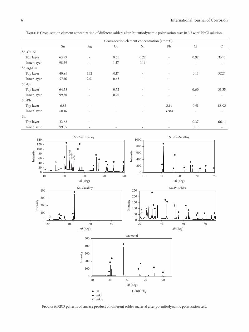