Embed Size (px)
Citation preview

NPL REPORT MATC(A)108
Corrosion and Cracking of
Weldable 13 Cr Martensitic
Stainless Steels –
A Review
A Turnbull and A Griffiths May 2002

NPL Report MATC(A)108
[13 Cr review 15/BM]
© Crown copyright 2002 Reproduced by permission of the Controller, HMSO
ISSN 1473 2734 National Physical Laboratory Teddington, Middlesex TW11 0LW, UK
Extracts from this report may be reproduced provided that the source is acknowledged
Approved on behalf of Managing Director, NPL, by Dr C Lea, Head, NPL Materials Centre

NPL Report MATC(A)108 May 2002
[13 Cr review 15/BM]
Corrosion and Cracking of Weldable 13 Cr Martensitic Stainless Steels – A Review
A Turnbull and A Griffiths Materials Centre
National Physical Laboratory Teddington, Middlesex TW11 0LW, UK
ABSTRACT A critical review of the literature has been undertaken to establish the current state of knowledge and understanding of the corrosion and stress corrosion cracking of 13 Cr martensitic stainless steels. To provide a framework for this, the service conditions oil and gas pipelines are subjected to are outlined in Section 1. In Section 2 corrosion data for conventional, weldable and alloyed 13 Cr martensitic stainless steels are critically evaluated to establish the conditions in which the various steels are in the active state, pitting or passive state and typical corrosion rates. The impact of steel composition and environmental exposure conditions are assessed also. In Section 3 data for hydrogen uptake and diffusivity in conventional AISI 410 steels and modified 13 Cr steels are reviewed. In Section 4 a selected sample of the recent literature on stress corrosion cracking of the modified 13 Cr steels is evaluated, with a view to identifying the impact of different service and laboratory test variables. The main emphasis in the discussion is on establishing a clear perspective on the best approach to testing.

NPL Report MATC(A)108
[13 Cr review 15/BM]
CONTENTS
FOREWORD .............................................................................................................................. i INTRODUCTION...................................................................................................................... 1 SECTION 1: CHARACTERISTICS OF SERVICE CONDITIONS......................................... 2
1.1 SERVICE ENVIRONMENTS ................................................................................ 2 1.1.1 Internal pipe solution chemistry ......................................................................... 2 1.1.2 External pipe surface conditions ........................................................................ 2
1.2 SERVICE STRESSES ............................................................................................. 2 1.3 REFERENCE ........................................................................................................... 2
SECTION 2: CORROSION AND ELECTROCHEMISTRY ................................................... 3 2.1 SCOPE OF REVIEW OF CORROSION LITERATURE................................... 3 2.2 CORROSION LITERATURE................................................................................ 3 2.3 ELECTROCHEMICAL MEASUREMENTS..................................................... 14 2.4 DISCUSSION ......................................................................................................... 15
2.4.1 Buffering of solution ........................................................................................ 15 2.4.2 Impact of solution composition and temperature on active vs pitting vs passive behaviour.......................................................................................................................... 17 2.4.3 Impact of material composition........................................................................ 20 2.4.4 Corrosion rates: time dependence .................................................................... 22 2.4.5 Matching vs duplex and super-duplex stainless steel weld consumables ........ 22
2.5 CONCLUSIONS..................................................................................................... 23 2.6 REFERENCES ....................................................................................................... 24
SECTION 3: HYDROGEN UPTAKE AND PERMEATION ................................................ 26 3.1 INTRODUCTION .................................................................................................. 26 3.2 HYDROGEN UPTAKE AND PERMEATION................................................... 26
3.2.1 AISI 410 ........................................................................................................... 26 3.2.2 Modified 13 Cr steels ....................................................................................... 28
3.3 CONCLUSIONS..................................................................................................... 34 3.4 REFERENCES ....................................................................................................... 35
SECTION 4: CRACKING SUSCEPTIBILITY OF MODIFIED 13 Cr STEELS ................... 36 4.1 INTRODUCTION .................................................................................................. 36 4.2 FORMATION/CONDENSATE WATERS ......................................................... 36 4.3 CATHODIC PROTECTION ................................................................................ 53 4.4 DISCUSSION ......................................................................................................... 56
4.3.1 Testing.............................................................................................................. 56 4.3.2 Residual stress, hardness and PWHT............................................................... 63 4.3.3 Impact of temperature....................................................................................... 63 4.3.4 Chloride concentration ..................................................................................... 64 4.3.5 Matching vs duplex SS filler............................................................................ 64
4.5 CONCLUSIONS..................................................................................................... 65 4.5 REFERENCES ....................................................................................................... 65
ACKNOWLEDGEMENTS ..................................................................................................... 68 APPENDIX 1 ........................................................................................................................... 69 APPENDIX 2 ........................................................................................................................... 70

NPL Report MATC(A)108
i [13 Cr review 15/BM]
FOREWORD The terms conventional, modified, alloyed and super 13 Cr weldable steels are used as material descriptors in the literature. Conventional steels will be assumed to include steels such as AISI 420 and also AISI 410, which has a slightly lower C content. Modified, alloyed and super 13 Cr weldable steels are often used for similar material specifications as there appears no consistent definition. Lean (1.0-2.5 Ni, <1 Mo), medium (2.5-4.5 Ni, 1.0-2.0 Mo) and fat (4.5-6.5 Ni, >2 Mo) have also been proposed as a means of distinguishing grades. When citing specific publications, the terms used therein will be employed. Otherwise, modified, alloyed and super terms will be assumed to be interchangeable but the Mo content should be apparent. Where the text refers to very low carbon 13 Cr steels with no significant Mo additions this will be clearly distinguished. The units of pressure adopted in the literature vary considerably, with bar, atmos, psi and MPa all used. To assist comparison, all pressures in this text will be expressed in MPa but the relationship to other units is listed in Appendix 1. The pH value of pure water decreases with increase in temperature. When gases such as CO2 are present the change in solubility and equilibrium constant add to the complexity. For these reasons, it is important when specifying a pH to distinguish whether the pH quoted is the measured or calculated value at the test temperature or the room temperature value (the value measured/expected if the gas mix were bubbled through at ambient temperature). In reporting the literature, we have quoted the values as specified by the authors, although sometimes unclear, but would recommend the use of a labelling system that enabled unambiguous distinction. In other work we have used pH273, pH353 for example to describe pH values at 20 �C and 80 �C respectively.

NPL Report MATC(A)108
[13 Cr review 15/BM] 1
INTRODUCTION The conventional 13 Cr steels have been used successfully as downhole tubulars for oil and gas production in sweet environments at elevated temperatures typically up to about 125 �C or so. However, the high carbon content poses problems for welding, making the steel unsuitable for oil and gas transmission lines. Carbon steel with inhibition has been used traditionally for pipelines but the cost of maintenance is a disadvantage. To achieve a balance of capital and maintenance costs in distributing fluids which are not too aggressive, 13 Cr steels with low carbon content, � 0.02%, were developed, with a range of Mo contents designed to give varying degrees of corrosion resistance according to the chloride concentration, pCO2, pH2S and temperature. In principle, the low C content enables the pipe to be welded satisfactorily, without post weld heat treatment. The range of materials suppliers has increased markedly and the steels have been adopted in a number of applications, with many more opportunities being considered. A wealth of data on the laboratory performance of these steels now exists, and is growing, but there remains controversy about the relevance of corrosion and environment assisted cracking tests of welded specimens/samples in relation to environmental simulation, surface condition, residual stress, and mechanical test method. The purpose of this review is to highlight some of the results obtained and to offer a perspective on the influence of operational and testing variables.

NPL Report MATC(A)108
[13 Cr review 15/BM] 2
SECTION 1: CHARACTERISTICS OF SERVICE CONDITIONS
1.1 SERVICE ENVIRONMENTS
1.1.1 Internal pipe solution chemistry
Pipelines/flowlines are used to transport oil or gas with the attendant issues from a corrosion perspective being the composition of the formation and condensed waters respectively. Formation waters originate in the geological formations in oil reservoirs and are extracted with the oil. A formation water will contain chloride ions with concentrations up to about 200,000 ppm with some bicarbonate also present, typically 100 ppm. CO2 pressures will vary according to the field although most laboratory studies focus in the range 0.5-4 MPa (5-40 bar) with H2S partial pressures typically 0.0004-0.01 MPa (4-100 mbar). The pH for these conditions may be about 4.5-5.0 because of the bicarbonate. Condensed water is produced in gas pipelines as the pressure and temperature decreases and will typically contain up to about 1000 ppm Cl- and no bicarbonate. Again, studies have often focused on similar partial pressures to the above. For these partial pressures of CO2 the pH of the condensate water would be about 3.2-3.9 depending on temperature. In both formation and condensate waters, temperatures can range from 5 �C to 160 �C.
The flow rate of the gas or oil will be high with occasional slug flow. In an oil-carrying pipe the soluble products of corrosion reactions would be well mixed with the fluid and passed along the pipe. In a gas-carrying pipe the condensed layer would be expected to be well-mixed because of the shearing of the gas at the gas-solution interface. Streaming may occur. Nevertheless, in both systems, dead-spots can arise and local chemistry variation may ensue.
1.1.2 External pipe surface conditions
The external surface will be exposed to seawater, and possibly mud, or soil, with the surface temperature ranging from 5 �C to 40 �C. In seawater, the pipe will be cathodically protected at potentials down to the sacrificial anode value (not less than –1100 mV SCE). In soils such as a desert environment with impressed current system the odd occasional potential shift to -1500 mV SCE might occur transiently. In principle, H2S from sulphate reducing bacteria in the mud or soil is feasible. For cathodically protected steel, the only possible mechanism of cracking is hydrogen embrittlement and therefore the key factors affecting cracking are the cathodic current density, the extent of absorption of hydrogen atoms and their distribution.
1.2 SERVICE STRESSES
The stresses in service comprise hoop stresses from internal pressure, residual stresses associated with welding, and bending stresses. The reeling and unreeling of pipe from a barge will result in cyclic plastic deformation1. The impact has been studied for a low-alloy carbon steel by ten Horn et al for 1% and 2.5 % strain amplitudes. Contrary to expectation perhaps, the steel did not work-harden but did exhibit a lowering of the yield strength. Assuming this behaviour carried over to 13 Cr martensitic steels it might be inferred that plastic deformation would ensue at a lower stress.
1.3 REFERENCE 1. C.H.L.J. ten Horn, A. Bakker, R.W. Koers, J.T. Martin and J. Zuidena, Paper
ICF100398OR, ICF10, Honolulu, Hawaii, Dec. 2001, Pergamon Press, 2001.
NPL Report MATC(A)108
[13 Cr review 15/BM] 3
SECTION 2: CORROSION AND ELECTROCHEMISTRY
2.1 SCOPE OF REVIEW OF CORROSION LITERATURE The scope of this section is not a fully comprehensive review of the literature but a constrained representative assessment to establish the conditions in which the various 13 Cr steels are in the active state, pitting or passive state, typical corrosion rates, the propensity for localised corrosion and the impact of steel composition and environmental exposure conditions. Relevant data for the welds will be assessed. In the latter context, it is important to distinguish the low carbon (<0.02%), low alloy, 13 Cr steels designed as an advance on the conventional steel to enable welding with some improvement in corrosion resistance, with steels with increased Mo (up to about 2.5%) aimed at intrinsically more corrosion resistance in high temperature, high chloride and high CO2 conditions with some H2S. 2.2 CORROSION LITERATURE Hashizume et al1 measured the depassivation pH of various low carbon 13 Cr steels with Mo varying from 0% to 1.9 % by exposing the steels to 5 % NaCl + 0.5 % CH3COOH with 0.0035 MPa H2S + 0.0965 MPa CO2 with the pH varied by addition of NaOH. The tests were conducted at 24 �C for 96 hours and the depassivation pH was determined from corrosion rate coupled with visual observation. The delineation of active and passive conditions was assessed in terms of a material composition factor dependent on Cr, Ni, Mo and C levels. The depassvation pH was between about 3.6 and 3.8. Although Mo was considered the primary factor in lowering the depassivation pH, the more noticeable feature is how little impact the composition had, with the depassivation pH decreasing by only 0.2 pH units over the full range of composition tested. Indeed the effect of Mo, analysed separately, was to decrease the depassivation pH by only about 0.1 pH units. Linne et al2 used a different procedure for estimating the depassivation pH, first pickling the sample, immersing in 120 g/l of NaCl and measuring the peak anodic current density. On this basis, a value of 1.3 was estimated for the modified 13 Cr steel (5.9 Ni, 2.0 Mo, 0.2 Ti) compared to 3.5 for the conventional alloy. This is markedly different from the work of Hashizume et al and the definition of the depassivation pH by Linne should not be relied on. Drugli et al3,4 observed active corrosion behaviour for modified 13 Cr steels (with 2 % Mo), coarse ground surfaces of base material and untreated weld specimens, in strongly buffered solution (4 g/L sodium acetate) at pH 3.5 (1 g/l NaCl, 0.1 MPa CO2, 0.0008 MPa H2S) at 20 �C. In the absence of buffering, the rise in pH at the metal-solution interface was sufficient to generate passive behaviour. This was true also for coupling to a carbon steel, with the lower potential enhancing the pH increase. However, when coupling was conducted in strongly buffered solution at 3.8, such that the 13 Cr steel was just passive when uncoupled, the 13 Cr steel became active at the lower potential associated with the carbon steel. Notably, when welded with super-duplex stainless steel filler the 13 Cr material showed active corrosion in the buffered pH 3.8 solution at 40 �C (uncoupled) yet the testing of the parent plate gave essentially passive behaviour. No explanation was given but local microstructural/ microchemical changes in the HAZ may be responsible. From a general perspective, the authors indicate that a weld with high relative area to parent plate is less likely to lead to
NPL Report MATC(A)108
[13 Cr review 15/BM] 4
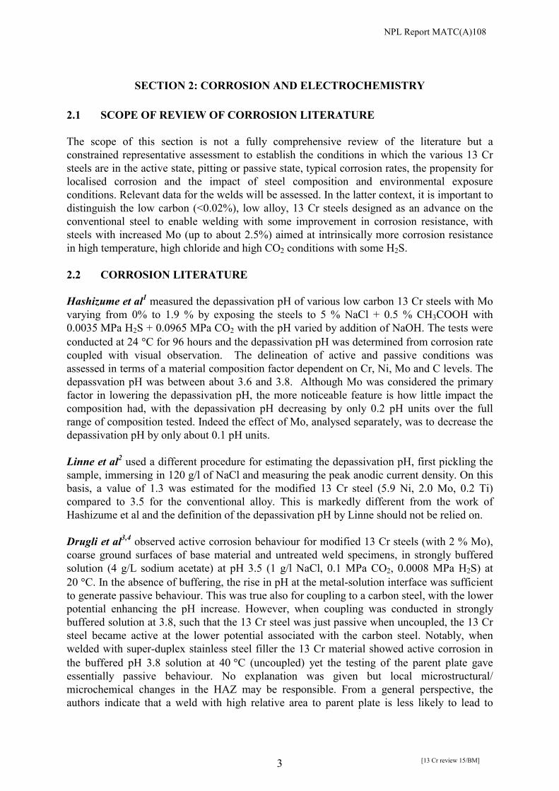
active corrosion because the mixed potential will remain higher and therefore passivity is more likely to be maintained. Data from several studies5,6,7 are summarised in Figure 1 showing the dependence on chloride concentration of the corrosion rate of the conventional and modified 13 Cr steels. For the modified steel in 10% NaCl or greater the corrosion rate is relatively high at 200 �C suggesting possibly active behaviour and at 150 �C is close to the 0.1 mm/y value often used as a threshold criterion for selection. For the AISI 420 or equivalent steel the corrosion rate was in the range of 1 mm/y to about 4 mm/y between 150 �C and 200 �C and NaCl concentrations between 5% and 20%. The corrosion rate tends to increase with NaCl concentration but there is some variability between laboratories. The modified steels had corrosion rates of about 0.2 mm/y in 5 % NaCl at 200 �C but increasing to 0.7 mm/y in 20% NaCl suggesting active behaviour. Interestingly, Sakamoto et al5 reported that the corrosion rate appeared to be relatively insensitive to H2S at 150 �C up to 0.1 MPa but with some sensitivity at 200 �C. The authors reported little effect of bicarbonate ion concentration. Since the steel appeared to remain in the active state for the range tested this simply indicates that the cathodic reduction of hydrogen ions is more significant than that of bicarbonate ions. The pH of the test solution at temperature would be calculated to lie between 3.4 and 3.7 at this pressure of CO2 (4 MPa). Curiously a higher Cu, no Mo, alloy performed best of all in their studies of different alloys which is a little surprising as Cu is sometimes perceived to mitigate against pitting corrosion by increasing general corrosion.
100 150 200 250 300
0.01
0.1
1
10
Approx. 420, 10% NaCl (Ref 7) 2 Mo, 10% NaCl (Ref 7) 420, 5% NaCl (Ref 5) 1.4 Mo/1.5 Cu, 5% NaCl (Ref 5) 1.4-2.0 Mo/1.5 Cu, 5% NaCl (Ref 6) 1.4-2.0 Mo/1.5 Cu, 20% NaCl (Ref 6) 420, 5% NaCl (Ref 6) 420, 20% NaCl (Ref 6)
Cor
rosi
on R
ate/
mm
/y
Temperature / oC
Figure 1. Corrosion rate for 13 Cr steels as function of NaCl concentration and temperature.
Tests in reference 7 had 3 MPa CO2 with 0.005 MPa H2S; others 4 MPa CO2.
NPL Report MATC(A)108
[13 Cr review 15/BM] 5
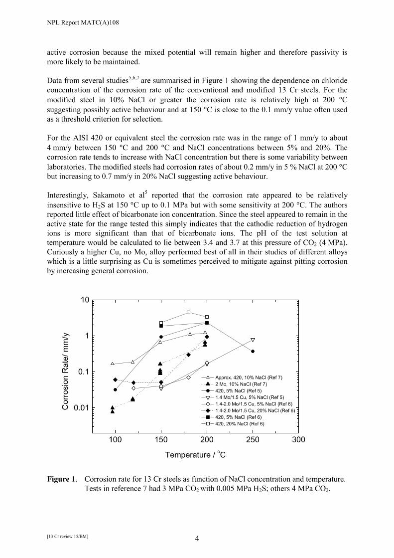
The tests conducted by Asahi et al6 were based on AISI 420 or a steel referred to as CRS with Ni (4.0-6.0), Mo (1.4-2.1) and Cu (1.0-2.0) with N (0.01-0.08) although the exact composition corresponding to the data of Figure 1 was not specified. Reassuringly, the corrosion rate data for the two steels are very similar to that measured by Sakamoto et al. Hashizume et al7 also measured the temperature dependence of the corrosion rate in 3 MPa CO2 but with 10 % chloride and with 0.005 MPa H2S. The lower partial pressure of CO2 is likely to be responsible for the lower corrosion rate of the AISI 420 steel compared with other studies in Figure 1. Popperling et al8 testing a 13 Cr low carbon steel (no Mo) in 5 % NaCl at 3 MPa CO2 also indicated fairly similar corrosion rates over the temperature range but noted the fall off in corrosion rate with exposure time (Figure 2). Such a time-dependence of course raises the issue of a suitable test duration for evaluating corrosion rates.
Figure 2. Corrosion rate of 13 Cr low carbon steel as function of time and temperature8. Miyata et al9 highlighted the role of Cu in limiting pitting corrosion, giving rise to more general corrosion (Figure 3).

NPL Report MATC(A)108
[13 Cr review 15/BM] 6
Figure 3. Corrosion rate as function of material composition in 20% NaCl with 3 MPa
CO29.
The impact of retained austenite on corrosion rate and pitting susceptibility of a modified 13 Cr steel quenched and then tempered to give varying levels of austenite between 3 and 40% was investigated by Kimura et al10. Tests were conducted at ambient temperature in various environments containing different levels of chloride, CO2 (0.1 MPa) and H2S (0.004 MPa) and pH values between 2.8 and 4.5. The essential result was that retained austenite had no impact for these conditions. Whilst the above studies have focused on high partial pressures of CO2 for which there would be most interest in the use of higher performance 13 Cr alloys, it is important to establish the range of conditions for application of conventional 13 Cr steels at low CO2 pressures when the steel is in the passive state. Huizinga and Liek11 measured corrosion rates for a API 5CT steel (with about 0.2% C) in a range of chloride and temperature conditions but with 0.5-0.7 MPa (5-7 bar) CO2. A mathematical relationship for the corrosion rate was derived and for the 0.1 mm/y limit it was deduced that the 13 Cr steel could be used up to 125 �C in the presence of 150 g/L of chloride. The choice of test solution chemistry was explored in detail by Amaya and Ueda12. The authors note that the addition of HCl as specified by the EFC guidelines would increase the chloride ion concentration significantly if testing condensate waters and some adjustment of chloride ion level would be required. The current EFC guidelines propose a solution of 0.4 wt% CH3COONa (4 g/L) with 0.23 % CH3COOH (2.3 g/L) to give a pH of 3.5 for testing at ambient pressure and temperature. The authors proposed lowering the concentration to 0.04 wt% CH3COONa (0.4 g/L) to give results more reflective of those obtained under CO2 pressure conditions. This proposal has now been accepted by the EFC Working Party on Corrosion in Oil and Gas Production and will be incorporated into the next revision of

NPL Report MATC(A)108
[13 Cr review 15/BM] 7
EFC 17. They note the formation of HCHO and its uncertain impact when testing with much higher CH3COOH concentrations. Ueda et al13 measured corrosion rates and made observation of pitting on conventional and super 13 Cr steels as shown in Figure 4.
Figure 4. Effect of temperature on corrosion rate, pitting corrosion and stress corrosion
cracking susceptibility of conventional, super 13 Cr OCTG steel and weldable super 13 Cr stainless steel in 5% NaCl, 3 MPa CO2, 0.001 MPa H2S13.
Figure 5. Effect of Mo content on pitting corrosion and corrosion rate of 13 Cr steels in
5% NaCl, 3 MPa CO2, 0.001 MPa H2S at 150 �C13.

NPL Report MATC(A)108
[13 Cr review 15/BM] 8
Notably, the corrosion rate of the welded specimen (super-duplex stainless steel welding material) was similar to that of the super 13 Cr steel, although measurements were made at only one temperature, 150 �C. No galvanic interaction was apparent and using a metal-metal crevice with the parent material interfacing with the weld, there was no evidence of crevice attack. The effect of Mo was also explored (Figure 5), the corrosion rate and the pitting susceptibility being low at 2 % Mo but being more significant at 1 % Mo for these test conditions. Surprisingly, with no Mo, the steel did not exhibit active corrosion despite the high pCO2 but it is not clear whether this was a conventional steel or a very low carbon steel. Abayarathna and Kane14 conducted 60-day exposure tests using corrosion coupons, the results for which are summarised in Table 1. There may appear some confusion over terminology, with the authors referring to both general corrosion and localised corrosion for the same conditions. In practice, pitting corrosion was more dominant at the lower temperature but at the higher temperature, pits were shallower and there was more evidence of more general attack. Pitting was observed for all 13 Cr steels even for the least aggressive environment but clearly from the corrosion rates (calculated from mass loss), the total current flow from the pits was less for the super 13 Cr steel containing 2.1 Mo and 5.5 Ni. Ideally, the depth of the maximum pit should have been measured (see Felton and Schofield below) as it is feasible that the more resistant alloy could lead to fewer pits forming but each having a greater pit growth rate compared to the less resistant alloy.

NPL Report MATC(A)108
[13 Cr review 15/BM] 9
Table 1. Corrosion data for 13 Cr steels14

NPL Report MATC(A)108
[13 Cr review 15/BM] 10
Felton and Scholfield15 measured general corrosion and pitting corrosion rates for a range of steels in simulated formation and condensed waters as summarised in Tables 2 to 5.
Table 2. Composition of steels tested15
NPL Report MATC(A)108
[13 Cr review 15/BM] 11
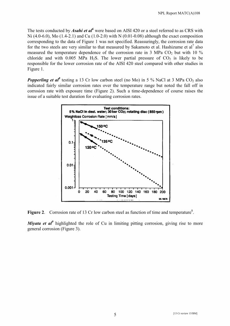
Table 3. General corrosion results (mm/y)15
In the case of pitting, the pit growth rate was determined from the depth of the deepest pit. The pH values are designated room temperature equivalents, i.e. the pH for the stated CO2 partial pressure and bicarbonate ion content of the environment at 20 �C, calculated from Crolet’s data. The actual pH at elevated temperatures is estimated to be about 0.4 units higher. There was no indication that the solution was stirred and it must be assumed to be stagnant. The authors refer to electrochemical measurements suggesting that for conventional 13 Cr steel, passive behaviour at 125 �C gave way to active behaviour at 150 �C whilst for the super 13 Cr steels active behaviour was reported for Test 6 conditions only. Unfortunately, Test 1 is referred to as low pH and Test 2 as high pH, which is confusing as they are nominally the same.

NPL Report MATC(A)108
[13 Cr review 15/BM] 12
Table 4. Pitting corrosion results (mm/y)15
Felton and Schofield suggest three categories of material: standard 13 Cr (e.g. 420), lower carbon 13 Cr (e.g. 410), and alloyed supermartensitic steels with very low carbon and with Mo and Ni additions. The impact of reducing the carbon is to limit the extent of dealloying of the matrix as Cr is lost in the formation of chromium carbides. Comparison of pit penetration rates is affected by the extent of general corrosion as only the relative depth of pit to the final surface position is measured making the growth rate appear small. The important feature is the high penetration rates for some of the supermartensitic steels. The authors ranked the environments as in Table 5.

NPL Report MATC(A)108
[13 Cr review 15/BM] 13
Table 5. Summary of test conditions
Most Corrosive 7 > 6 � 5 > 1 > 4 > 2 � 3 Least Corrosive They indicate a strong effect of temperature and pH but claim a more modest effect of chloride ion concentration. They also allude to the fall-off in pit growth rates with exposure time, which is to be expected as pit growth decreases with increasing depth because of IR drop and mass transport effects. An additional factor is that there is essentially a fixed amount of cathodic current (reduction of hydrogen ions) to support the total pit current. Initially when the pit area is small and numbers of pits small, the growth rate is high. However, as the pit area increases and the number of pits increase, the growth rate of individual pits must decrease since the total current must remain the same (see also work by Case et al below). It highlights the general concern about the impact of test time and emphasises the need for staged testing with specimens exposed for varying periods of time. Interestingly, in the limited testing conducted by Felton and Schofield, the corrosion rate of the super 13 Cr steels was not much different when testing for 14 or 30 days, in contrast to the data of Popperling et al8. Enerhaug et al16 reported testing of super 13 Cr steels welds, with super duplex stainless consumable, in formation water (1.5 MPa CO2 with 0.0004 MPa H2S) at ambient temperature in which corrosion initiated on the machined side edges of the HAZ only. If these were coated, no corrosion of the sample occurred. Formation water was more severe in terms of corrosion than condensate water despite the lower pH of the latter. They noted that use of the EFC buffered solution with 4 g/L NaAc gave active corrosion at ambient temperatures but when using 1g/L NaCl with 0.4 g/L NaAc and acidification by acetic acid to pH 3.5, or real CO2 partial pressure (but only 1.5 MPa), to simulate condensate water, active corrosion was avoided. Most interestingly, they observed that the protectiveness of the oxide in simulated formation water was lowest near ambient temperature, the repassivation being slower and its properties different compared with elevated temperatures of 90 �C and 140 �C. In relation to the surface state following welding they report that proper cleaning of mill scale from the pipe surface (by pickling or blasting) is necessary to obtain optimum corrosion properties. Corrosion studies of 13 Cr steels with matching weld consumables have been conducted by Olsen et al and by Kimura et al. Olsen et al17 were inconclusive with respect to the impact on HAZ corrosion in going from the duplex filler to the matching filler but with the suggestion for more optimisation of welding parameters. Kimura et al18 claimed similar corrosion
NPL Report MATC(A)108
[13 Cr review 15/BM] 14
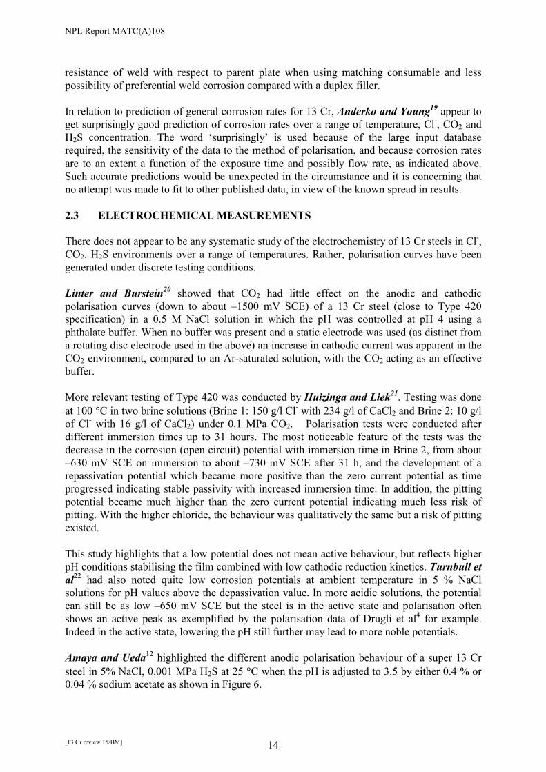
resistance of weld with respect to parent plate when using matching consumable and less possibility of preferential weld corrosion compared with a duplex filler. In relation to prediction of general corrosion rates for 13 Cr, Anderko and Young19 appear to get surprisingly good prediction of corrosion rates over a range of temperature, Cl-, CO2 and H2S concentration. The word ‘surprisingly’ is used because of the large input database required, the sensitivity of the data to the method of polarisation, and because corrosion rates are to an extent a function of the exposure time and possibly flow rate, as indicated above. Such accurate predictions would be unexpected in the circumstance and it is concerning that no attempt was made to fit to other published data, in view of the known spread in results. 2.3 ELECTROCHEMICAL MEASUREMENTS There does not appear to be any systematic study of the electrochemistry of 13 Cr steels in Cl-, CO2, H2S environments over a range of temperatures. Rather, polarisation curves have been generated under discrete testing conditions. Linter and Burstein20 showed that CO2 had little effect on the anodic and cathodic polarisation curves (down to about –1500 mV SCE) of a 13 Cr steel (close to Type 420 specification) in a 0.5 M NaCl solution in which the pH was controlled at pH 4 using a phthalate buffer. When no buffer was present and a static electrode was used (as distinct from a rotating disc electrode used in the above) an increase in cathodic current was apparent in the CO2 environment, compared to an Ar-saturated solution, with the CO2 acting as an effective buffer. More relevant testing of Type 420 was conducted by Huizinga and Liek21. Testing was done at 100 �C in two brine solutions (Brine 1: 150 g/l Cl- with 234 g/l of CaCl2 and Brine 2: 10 g/l of Cl- with 16 g/l of CaCl2) under 0.1 MPa CO2. Polarisation tests were conducted after different immersion times up to 31 hours. The most noticeable feature of the tests was the decrease in the corrosion (open circuit) potential with immersion time in Brine 2, from about –630 mV SCE on immersion to about –730 mV SCE after 31 h, and the development of a repassivation potential which became more positive than the zero current potential as time progressed indicating stable passivity with increased immersion time. In addition, the pitting potential became much higher than the zero current potential indicating much less risk of pitting. With the higher chloride, the behaviour was qualitatively the same but a risk of pitting existed. This study highlights that a low potential does not mean active behaviour, but reflects higher pH conditions stabilising the film combined with low cathodic reduction kinetics. Turnbull et al22 had also noted quite low corrosion potentials at ambient temperature in 5 % NaCl solutions for pH values above the depassivation value. In more acidic solutions, the potential can still be as low –650 mV SCE but the steel is in the active state and polarisation often shows an active peak as exemplified by the polarisation data of Drugli et al4 for example. Indeed in the active state, lowering the pH still further may lead to more noble potentials. Amaya and Ueda12 highlighted the different anodic polarisation behaviour of a super 13 Cr steel in 5% NaCl, 0.001 MPa H2S at 25 �C when the pH is adjusted to 3.5 by either 0.4 % or 0.04 % sodium acetate as shown in Figure 6.

NPL Report MATC(A)108
[13 Cr review 15/BM] 15
Figure 6. Anodic polarisation curves of super 13 Cr steel in solutions of 5% NaCl, 0.001 MPa H2S, 0.99 MPa CO2 at 25 �C with the pH adjusted to 3.5 by either 0.4 % CH3COONa or 0.04 % CH3COONa.
The potential of the steel in Solution 1 but with an Ar gas mix was similar at about -0.4 V (SCE). The authors argue that the high acetate concentration affects the stability of the passive film directly. Case et al23 focused on the impact of H2S concentration on pitting corrosion of modified 13 Cr steels, base material and weld, in a solution of 7% NaCl with 0.4 g/l of sodium acetate and the pH adjusted to 4.5 with HCl. Tests were at 25 �C. They emphasised that anodic polarisation beyond the redox potential for the S/H2S reaction (-277 mV SCE for 1% H2S, 0.001 MPa and –307 mV for 10% H2S, 0.01 MPa) is of no value in investigating pitting corrosion as the oxidation of H2S becomes predominant. The weld showed a lower passive current than the base plate but a greater susceptibility to pitting as expressed by the lower repassivation potential, with pitting very close to the fusion line. Tests without H2S confirmed the key role of H2S for pitting for these exposure conditions. On the base metal, pit growth rates would be tolerable at 1% H2S (about 0.1 mm/y close to the corrosion potential) but not for the weld metal for which the growth rates were about an order of magnitude or more higher. The authors note that due to transport limiting factors in H2S access to the pit, growth rates can be significantly higher at ambient temperature where pits tend to be open than at higher temperatures where the oxide film is more protective and access to the pit base more difficult, consistent with the work of Ueda et al24. 2.4 DISCUSSION 2.4.1 Buffering of solution In laboratory measurements aimed at selection of materials for service specific conditions it is important to replicate service environments. Although the broad chemistry described for formation or condensate water should be simulated in application-specific tests, the mass

NPL Report MATC(A)108
[13 Cr review 15/BM] 16
transport of solution in service has to be considered also because this will determine the local chemistry at the metal surface. The problem for laboratory testing is often that tests are carried out for pragmatic reasons under stagnant flow conditions without refreshment and with no forced convection or with flow conditions that are not related to service conditions. In addition, in autoclave tests at elevated temperature there is usually a fixed amount of CO2 and/or H2S with the assumption that these are not diminished during the course of the test. Tests should always be designed so that the bulk chemistry does not change significantly. For long exposure tests when the steel is actively corroding, this may become an issue if the metal area to solution volume is high. Under corroding conditions the pH will always tend to rise, particularly at the metal-solution interface. Although by definition of free corrosion conditions the anodic and cathodic currents are equal, the cathodic reduction of hydrogen ions consumes one hydrogen ion per electron but the generation of hydrogen ions by metal ion dissolution is much less efficient because of the intermediate hydrolysis constant which by being an equilibrium process is inherently incomplete. In well-stirred solutions, mixing ensures maintenance of the bulk chemistry at the metal surface whether in service or in the laboratory. The issue of pH changes local to the metal surface is certainly an issue when the steel is in the active state with a high corrosion rate. In the passive state, with a relatively low dissolution rate, the elevation in pH at the surface would tend to be more modest but would depend on the magnitude of the passive current density. There is controversy about the use of artificial buffers (as distinct from bicarbonate which may be considered a natural buffer in formation waters) to maintain the pH constant at the metal-solution interface. These buffers were intended originally for ranking or comparative tests but have been used much more loosely and with less thought to the implications. The buffers are based on x g/l CH3COONa with acidification of the environment to the desired value by HCl or by CH3COOH. The main issue is the amount of sodium acetate buffer. The current EFC guidelines25 are based on 4 g/l (0.4 %) but as indicated in the previous section, at the meeting of the EFC Working Party on Corrosion in Oil and Gas Production in September 2001 it was agreed to recommend a weaker buffering solution of 0.4 g/L (0.04 %) sodium acetate for supermartensitic stainless steels. This concentration of sodium acetate (0.4 g/L) is now the recommended value in the draft ISO document (ISO 15156) for martensitic stainless steels. It is argued by a number of authors that strong buffering does not represent the chemistry when testing in the relevant high pressure CO2 atmosphere. This includes situations when 13 Cr steel is coupled to carbon steel. Here, the tendency for the alkaline pH expected for the 13 Cr steel acting as the net cathode is restrained by the buffer with the consequence of film reduction at the lower coupling potential. However, most of these tests are conducted in relatively stagnant conditions where pH elevation at the surface may occur. Hence, the criticism of strong buffering is something of a red herring as far as the pH is concerned since it is pertinent when testing in the CO2 atmosphere to consider the impact of flow and how it is related to service where solution mixing would be very effective on the whole. In that context, a well-buffered solution would reflect well-mixed conditions in service. The more important issue for buffering is not the maintenance of the pH per se, as its significance there is clear, but whether the particular buffer agent alters the stability of the

NPL Report MATC(A)108
[13 Cr review 15/BM] 17
passive film directly. There is concern expressed by Amaya and Ueda that acetate at high concentrations can indeed do that, leading to passivity breakdown. However, the defining experiment of testing the two levels of acetate concentration under very well-mixed and refreshed conditions designed to maintain the surface pH constant has not been undertaken. Their assessment is of concern but should be put on hold until such confirmation. Nevertheless, in any system the buffer content used should be the minimum amount required to maintain the surface and bulk solution pH constant. Of course, it should be apparent that a singular pH value (buffered solution designed for ranking tests) would reflect a specific pCO2 and cannot be considered to predict absolute behaviour when the pCO2 is inconsistent with that value. This may seem obvious but comments in the literature indicating incompatibility of buffered tests and tests in CO2 in relation to the existence or otherwise of active corrosion suggest that this is not always apparent. Also, a buffer to control the pH at 3.5 at ambient temperature will inevitably generate a different pH at elevated temperature and comparison with a pCO2-determined pH at temperature cannot be made directly. In addition, the nature of the films formed in a simulated formation fluid or condensed water will be dependent on the detailed chemistry and a buffering solution using acetate may not be relevant. Testing with sodium acetate and acetic acid mixtures with CO2 or CO2/H2S mixed gases may result in a change in bicarbonate level unless the pH happens to coincide with that predicted for the pCO2 on it own. Some of the debate on buffering centres partly around the difficulty in dealing with the issue of pitting corrosion since this activates by virtue of local variations in solution chemistry, particularly pH, in regions of favourable topography. If the buffering were too strong, such local chemistry development would not occur. In this case, buffering does not necessarily represent well-mixed conditions in relation to service since the acetate ions can migrate into a pit preventing build up of chloride ions. Hence, within the constraint that the buffer anion should not have a direct effect on corrosion, the use of well-buffered solutions may appear conservative for general, active, corrosion (including coupling to carbon steel), but will tend to give non-conservative results with respect to pitting susceptibility. Since the steel is otherwise in the passive state when pitting is a concern, buffering such a solution may not be necessary, depending on the magnitude of the passive current. An assessment of the effect of pH on pitting corrosion when the steel is already in the passive state would be of interest. The ideal solution is to explore more carefully the effect of solution flow in laboratory testing with simulated service environments but this can be cost prohibitive for ranking tests. In this circumstance, improved awareness of the purpose of the test in relation to service simulation is necessary when selecting environmental conditions for testing and when interpreting the results in terms of alloy performance. 2.4.2 Impact of solution composition and temperature on active vs pitting vs passive behaviour It is important to isolate regions of active corrosion, pitting corrosion and passive behaviour because of their impact on likely SSC susceptibility. The domain of active corrosion is sometimes identified by the corrosion potential but this can be misleading as the difference in

NPL Report MATC(A)108
[13 Cr review 15/BM] 18
potential between the steel undergoing active corrosion, pitting corrosion on an otherwise passive surface, and passive behaviour in pH values of 5.0 say may not be readily distinguishable, as described in the electrochemical section. As a consequence, it is common to use visual inspection to define the condition, unless specific electrochemical polarisation studies are undertaken. The key questions to address are the impact on the corrosion mode, active, pitting or passive corrosion (and their rates) of CO2, Cl-, H2S, temperature and material composition. The ideal way to evaluate these factors would be a careful study for different alloys over a range of temperatures and flow conditions with the latter controlled to ensure solution changes at the metal surface are minimised. In practice, consistent approaches to testing are not apparent in the literature and this leads to some difficulty in drawing specific comparisons and mapping out corrosion domains based on a consistent test framework.
Conventional 13 Cr steels
It is important to remember that the conventional 13 Cr steels have reasonable corrosion resistance (i.e. exhibit passivity) in less acidic environments in the absence of H2S. Huizinga and Liek11 have shown that 13 Cr steels can be used up to 125 �C in 150 g/L of chloride for CO2 partial pressures less than 1 MPa.
Felton and Schofield15 noted that at 125 �C, the standard 13 Cr steel exhibited semi-passive behaviour (some pitting) in high pH solution (pH 4.3), active corrosion at 150 �C and active corrosion at 130 �C in low pH solution (pH 3.5). The solution was 90,000 ppm Cl- with 0.01 MPa H2S and 1 MPa CO2. All pH values are calculated values for the room temperature equivalent, i.e. the values if the temperature were 20 �C. The pH at temperature was expected to be about 0.4 higher.
Hence, for the conventional steels an upper temperature of about 125 �C with 150 g/L of chloride and pCO2 less than 1 MPa would be implied but the presence of H2S, even at low levels, will cause pitting. The critical level of H2S at different temperatures is not so well established but even 0.001 MPa is sufficient to induce pitting in 5 % NaCl with 0.1 MPa CO2 at ambient temperature (pH 4.3). Low carbon 13 Cr steels Popperling et al8 observed that the corrosion rate of low carbon (0.02 C) 13 Cr steels is similar to that of the Ni and Mo containing steels in 5.8 % NaCl (58,000 ppm) with 3 MPa CO2 for temperatures below 120 �C, and presumably passive, but the more alloyed materials are more resistant at elevated temperatures (all short term tests). Alloyed 13 Cr steels H2S-free Amaya et al26 studied a conventional 13 Cr steel and alloys with 0.7% Mo and 2 % Mo at 175 �C with 3 MPa CO2 and 25 % NaCl. Whilst the conventional steel suffered general corrosion, the other steels exhibited a relatively low passive current with no localised attack, which was confirmed by anodic polarisation measurements showing a high pitting potential relative to the corrosion potential.

NPL Report MATC(A)108
[13 Cr review 15/BM] 19
Cooling et al27 measured corrosion rates for alloyed 13 Cr steel (1%-2% Mo) at temperatures between 150 �C and 200 �C in a simulated produced water (20 % NaCl) and a simulated condensing water (0.17 % NaCl) with pH values of 3.5 and 4.5 (buffered by a CO2/bicarbonate mix but how effective this would be in limiting pH changes at the surface was not discussed). Either no corrosion or light general corrosion was observed with corrosion rates less than 0.16 mm/y at the highest temperature. The implication is that a protective layer was present which was considered to consist of a tenacious oxide/carbonate film rich in chromium. In relation to the data of Figure 1, active corrosion would be inferred (or at least the corrosion rate is relatively high) at chloride concentrations of 20% in 4 MPa CO2 at 200 �C. Even at about 180 �C, the corrosion rate of about 0.3 mm/y in the high chloride environments would tend to rule out selection. At 5% chloride, passivity could be assumed up to 200 �C. Summarising this sub-section, the modified steels with 1% - 2% Mo exhibit passive-like behaviour to 200 �C with 5% NaCl or less in the absence of H2S and with room temperature equivalent pH values not less than 3.5. At 20% NaCl with 3-4 MPa CO2,, passivity would seem to prevail at 150 �C but at higher temperatures there is less consistency in the corrosion rate data which may reflect differences in material or test set-up. These results reflect tests in unstirred solutions with the efficacy of the buffering in relation to surface pH possibly uncertain. H2S-containing It is not clear what the pH limit (and hence pCO2 limit) is for these steels at different temperatures in the presence of H2S. Cooling et al27 claim only a slight increase in corrosion rate with 0.01 MPa H2S, with no pitting. The polarisation data of Felton and Schofield28 for a modified 13 Cr at 180 �C in 5% NaCl with 0.01 MPa H2S and 1 MPa CO2 (the room temperature equivalent pH was 3.5) would suggest passive behaviour for this environment (the data in the figure are mislabelled). The authors later suggest15 that the steel was in the active state in the 20% NaCl, which is not consistent with the conclusions of Cooling et al. It is interesting to note that the super 13 Cr steel was reported3,4,7 as being in the active state at ambient temperatures in a strongly buffered solution of pH 3.5 in 5% NaCl (or 1% NaCl) with less H2S than used by Felton and Schofield15,28 when observing passivity at 180 �C. This may represent an increasing stability of the passive film at higher temperatures but may reflect also a higher pH both in the bulk (the pH is higher at higher temperatures for the same conditions of CO2) or at the surface as the solution would appear to have unstirred. Hence, H2S will affect the transition from passive to pitting to active behaviour but the critical values for this transition are not well defined for the range of alloys at different temperatures and solution composition. The results above might suggest a value of just 0.001 MPa should be assumed to be sufficient to induce pitting corrosion. This is supported by the work of Case et al23 using a 13 Cr steel with about 2% Mo in which 0.001 MPa of H2S was sufficient to induce pitting in 7 % NaCl at ambient temperatures. However recall that these authors noted that due to transport limiting factors in H2S access to the pit, growth rates can be significantly higher at ambient temperature where pits tend to be open than higher temperatures where the

NPL Report MATC(A)108
[13 Cr review 15/BM] 20
oxide film is more protective and access to the pit base more difficult, consistent with the work of Ueda et al24. The work of some authors (e.g. Figure 4) would suggest that increasing the temperature would make the 13 Cr steels more susceptible to localised corrosion as would normally be expected. However, Enerhaug et al16 concluded that the susceptibility of supermartensitic welds in simulated formation water was greatest at ambient temperatures. The distinction is probably associated with the state of the surface with the inference that the characteristics of the welded surface play a role. This was confirmed subsequently by Enerhaug et al29, who indicated that the oxide film formed upon welding had a much poorer resistance when tested directly in a H2S-containing environment than when tested after pre-exposure to a less aggressive environment such as fresh water, the latter being considered more appropriate to initial service conditions. The view is that some chromium depletion occurs during welding, giving rising to a low pitting potential. With exposure to an oxidising but otherwise benign environment, the film gradually transforms to a more resistant passive layer, the key issue being the timescale over which this transition occurs and how best to simulate this in the laboratory. In the latter case, application of a galvanostatic anodic current (1 �A cm-2) was used to simulate an oxidising condition. In response to the applied current, the potential of the ground surface increased almost immediately to a relatively high value. This indicates a resistant film, the potential having to rise quite high to find a reaction to respond to the current demand. For the as-welded surface an initial slow progressive increase occurred indicating existing activity at a low potential. This behaviour could reflect a ‘high’ passive current or susceptible localised regions. The transition to a more resistant surface was accelerated by increasing temperature and this may explain the apparent improved resistance to pitting in the higher temperature tests. The focus has been on pitting corrosion, which will manifest itself when the pH is above the depassivation pH for active corrosion but the temperature, chloride and H2S concentration are sufficient to cause localised breakdown of passivity. In the presence of crevices, as might be found at the toe of a weld on occasion, the external conditions for breakdown of passivity are less severe because the crevice itself will draw in anions from the bulk leading to a more concentrated chloride solution locally. Summarising this sub-section, H2S at a concentration of 0.01 MPa was reported by Cooling et al to result in only a slight increase in corrosion rate in 20 % NaCl (nominal pH 3.5), up to 200 �C, with no pitting but would lead to active corrosion at 180 �C according to Felton and Schofield15,28. In the 5% NaCl solution, passivity was reported at 180 �C but at ambient temperature tests in environments similar to that tested by Felton and Schofield active behaviour was observed (using buffers to sustain the pH). Pitting at ambient temperature was induced in 7% NaCl buffered at 4.3 with just 0.001 MPa H2S. Careful consideration has to be given to pre-conditioning of the surface after welding. 2.4.3 Impact of material composition A detailed discussion of the quantitative impact of material composition would be repetitive of much of the above and only a qualitative description will be given. In broad terms, the effect of material composition is well understood.

NPL Report MATC(A)108
[13 Cr review 15/BM] 21
Lower carbon content as well as improving welding properties gives improved resistance to pitting and general corrosion as a consequence of reduced carbide (Cr23C6) formation and associated Cr depletion. Ni being an austenite stabilising element is used to obtain a fully austenitic material during hot working and then a fully martensitic material without any delta ferrite phase2. It is added to compensate for reduced hot workability associated with introduction of Mo and lowered C and N. Addition of elements such as Mn and Cu aids austenite formation whilst Cr and Si lower ferrite formation9. Corrosion resistance is considered to be improved by the addition of Ni, but Felton and Scholfield28 report work by Miyasaka and Ogawa30 suggesting that low Ni contents can be detrimental whilst high contents (4%-5%) are beneficial. The addition of Mo improves pitting resistance and enhances passivity. This can be by a combination of producing a more resistant passive film by assisting in networking the protective layer, reducing the anodic peak making the transition from active to passive behaviour easier and reducing the dissolution rate for the exposed substrate making it more difficult to sustain the local chemistry necessary for localised corrosion. Mo, with Ni, has been shown13 to be enriched (factor of 5) on the outer layers of the passive film (with relatively small levels of Cr) with enrichment of Cr in the inner layer. In the presence of H2S, Mo is considered to form MoS giving protectiveness. This prevents H2S access to the underlayer, consisting of solely chromium oxide. Whilst the protective effects of Mo are evident in much of the data reported above, the lack of significant influence on the pH for depassivation is a little surprising. Ozozawa et al31 claim that N works by creating a locally elevated pH at the surface when going into solution. This elevation of pH would limit the development of pits and crevices. In an XPS study of conventional 13 Cr steel, Fierro et al32 concluded that CO2 encourages growth of Cr oxide in preference to Fe oxide in the outermost layers of the film but does not form a carbonate (at ambient temperature). SIMS analysis by Amaya et al26 of a modified 13 Cr steel surface exposed for 48 hours to 14000 Cl-, 2.7 MPa CO2 at 150 �C, indicated a 30 nm Cr-enriched layer with no obvious carbonate. At ambient temperature in 0.01 M H2S, Mo and Ni were enriched in the outer layer (forming sulphides), Cr in the inner layer. Various empirical formula to account for the impact of composition on corrosion have been proposed. Hashizume et al7 derived a general corrosion index, Cr-12C+0.77Ni+10N, which is very similar to that of Barteri et al33. The data were based on testing at 200 �C in 10 % NaCl with about 3 MPa CO2 and 0.005 MPa H2S. In relation to pitting, an index was derived at 30 �C in 3.5% NaCl at pH 4 which was Cr-12C+Mo+1.1Ni+6N (mass %). These indices are a little arbitrary being based on specific test conditions but they indicate general trends. However, Masamura et al34 suggest a negative influence of N in conventional 13 Cr steel, which they associate with the formation of Cr2N.

NPL Report MATC(A)108
[13 Cr review 15/BM] 22
2.4.4 Corrosion rates: time dependence General corrosion rates will often show a time-dependence, usually falling off with time over some initial period at least. Several factors can be important: thickening of the passive film when the steel is in the passive state; build up of corrosion product/films (including sulphide films on the surface in the active state; loss in aggressivity of the solution with time. The last of these is an artefact and should be isolated in any experimental study. There is conflicting evidence for this system in relation to the time-dependence of corrosion rates, which may reflect test method differences. Popperling et al showed a gradual but continuous fall-off of corrosion rate with time (Figure 2) that they attributed to increased passivation. In contrast, Felton and Schofield15 reported no difference in general corrosion rates for tests lasting 14 days and 30 days but noted that higher corrosion rates (factor of 2.5-9.3 relative to average for days 2-30) were observed on the first day. They also note that pit diameters increase with time whilst the rate of increase of pit depth decreases quite significantly with exposure period. This is to be expected generally because of restricted mass transport or IR drop in the pit. As Case et al23 noted, access to the bottom of the pit can be become more difficult at elevated temperatures because of oxide coverage. It would be of value to standardise the exposure period for mass loss/pit growth rate determination when comparing materials, or, preferably, testing for at least two different exposure periods. 2.4.5 Matching vs duplex and super-duplex stainless steel weld consumables The key factors with welding consumables from a corrosion perspective are coupling between the filler and adjacent heat affected zone and parent plate material, variations in the local microstructure/microchemistry in the fusion line region and heat affected zone. Other features such as residual stress, hardness, strength level, and porosity will be discussed in the section dealing with testing of 13 Cr steels for cracking resistance. The range of corrosion studies of welded joint with respect to environmental variables and temperature is very much less extensive than for the parent plate itself. Whilst Kimura et al10 indicated similar corrosion rates for matching welds and parent plate, he also noted that the ‘possibility for occurrence of preferential corrosion in matching welded joint was smaller than that in duplex stainless welded joint’ although it was not clear whether this was based on testing or just an assumption. Quite evidently, when conditions are sufficient severe, a weld with a duplex stainless steel filler will experience corrosion preferentially in the 13 Cr steel simply because of the lower alloying content. If coupling is sufficient to raise the potential locally prior to breakdown, then this would lead to pitting close to the fusion line in less severe conditions than for the parent plate on its own or with a matching consumable. There would also be the possibility of enhanced pit growth kinetics in the early stages of pit development with a duplex SS consumable.

NPL Report MATC(A)108
[13 Cr review 15/BM] 23
2.5 CONCLUSIONS �� There is a confused perspective on testing with buffered solutions that reflects a
misunderstanding of testing designed for ranking purposes and that aimed at simulating service conditions. Unfortunately, in the latter case criticism of the use of buffered solution is based often on laboratory testing in which the high flow and well-mixed conditions of service are rarely replicated.
�� The ideal approach is to explore more carefully the effect of solution flow in laboratory
testing with simulated service environments but this can be cost prohibitive for ranking tests. In this circumstance, improved awareness of the purpose and limitations of the ranking test in relation to service simulation is necessary when selecting environmental conditions for testing and when interpreting the results in terms of alloy performance.
�� Adopting conservative test conditions, buffered solutions for identification of active
corrosion at ambient temperatures and unbuffered solutions for pitting corrosion might seem prudent but investigation of the effect of pH and flow rate needs more study before this can be recommended. There is particular concern that acetate may affect the stability of the passive film directly, giving rise to active behaviour, but the key experiment to test the two levels of acetate concentration under very well-mixed and refreshed conditions designed to maintain the surface pH constant has not been undertaken. Nevertheless, in any system the buffer content used should be the minimum sufficient to maintain the surface and bulk solution pH constant.
�� Ideally, corrosion rates and pit growth kinetics should be determined by staged testing
with specimens exposed for varying periods of time. �� There would be long-term value in establishing a database of corrosion performance,
using neural networks for extended predictions, but the more modest review above suggests some inconsistencies in interlaboratory comparison that may relate to test duration and conditions. Nevertheless, there is sufficient information to describe reasonably the envelope of acceptable conditions for the modified 13 Cr steels.
�� For the conventional steels an upper temperature of about 125 �C with 150 g/L and pCO2
less than 1 MPa would be implied but pitting would occur if H2S is present, even at low levels. The critical level of H2S at different temperatures is not so well established but even 0.001 MPa is sufficient to induce pitting in 5 % NaCl with 0.1 MPa CO2 at ambient temperature (pH 4.3).
�� In the absence of H2S, the modified steels with 1% - 2% Mo exhibit passive-like
behaviour to 200 �C with 5% NaCl or less in the absence of H2S and with room temperature equivalent pH values not less than 3.5. At 20% NaCl with 3-4 MPa CO2, passivity would seem to prevail at 150 �C but at higher temperatures there is less consistency in the corrosion rate data which may reflect differences in material or test set-up. These results reflect tests in unstirred solutions with the efficacy of the buffering in relation to surface pH possibly uncertain.

NPL Report MATC(A)108
[13 Cr review 15/BM] 24
�� In H2S-containing environments, mapping out the domains of corrosion is more problematic as the data appear less consistent. A concentration of 0.01 MPa was reported to result in only a slight increase in corrosion rate in 20 % NaCl (nominal pH 3.5), up to 200 �C, with no pitting whilst elsewhere active corrosion was reported at 180 �C (1 MPa CO2 with room temperature equivalent pH of 3.5). In 5% NaCl solution, passivity was reported at 180 �C (1 MPa CO2) but at ambient temperature tests in a similar environment active behaviour was observed (using buffers to sustain the pH). Pitting at ambient temperature was induced in 7% NaCl buffered at 4.3 with just 0.001 MPa H2S.
�� The pit propagation rates appear to decrease with increasing temperature reflecting the
relative ease of H2S access. There is also evidence that as-welded samples have poorer pitting resistance at ambient temperatures which is considered due to the formation of an oxidised layer, perhaps depleted in chromium. However, it is argued that in service this layer is exposed initially to relatively benign fresh water conditions and transforms to a more protective layer before exposure to an aggressive environment. There is a need to account for this in laboratory testing not least because differences in shielding gases may affect the surface film, giving rise to considerable variability.
2.6 REFERENCES 1. S. Hashizume, Y. Inohara and K. Masamura, Corrosion 2000, Paper No. 00130, NACE
Int., Houston, 2000. 2. C. P. Linne, F. Blanchard, G.C. Guntz and B.J. Orlans-Joliet, Corrosion 97, Paper No. 28,
NACE Int., Houston, 1997. 3. J.M. Drugli, T. Rogne, M. Svenning and S. Axelsen, Corrosion 99, Paper No. 586, NACE
Int., Houston, 1999. 4. J.M. Drugli, T. Rogne, M. Svenning and S. Axelsen, Supermartensitic Stainless Steels 99,
Paper No. S99-37, 315, Belgian Welding Institute, 1999. 5. S. Sakamoto, K. Maruyama and H. Kaneta, Corrosion 96, Paper No. 77, NACE Int.,
Houston, 1996. 6. H. Asahi, T. Hara and M. Sugiyama, Corrosion 96, Paper No. 61, NACE Int., Houston,
1996. 7. S. Hashizume, Y. Inohara, Y. Minami and K. Masamura, Supermartensitic Stainless
Steels 99, Paper No. S99-36, 307, Belgian Welding Institute, 1999. 8. R. Popperling, K.A. Niederhoff, J. Fliethmann and M. Keller, Corrosion 97, Paper no. 38,
NACE Int., Houston, 1997. 9. Y. Miyata, M. Kimura and T. Koseki, Corrosion 97, Paper No. 19, NACE Int., Houston,
1997. 10. M. Kimura, Y. Miyata, T. Toyooka and Y. Kitahaba, Corrosion 2000, Paper No. 00137,
NACE Int., Houston, 2000. 11. S. Huizinga and W.E. Liek, Corrosion 97, Paper No 39, NACE Int., Houston, 1997. 12. H. Amaya and M. Ueda, Corrosion 99, Paper No. 585, NACE Int., Houston, 1999. 13. M. Ueda, H. Amaya, K. Kondo, K. Ogawa and T. Mori, Paper No. 58, Corrosion 96,
NACE Int., Houston, 1996. 14. D. Abayarathna and R.D. Kane, Corrosion 97, Paper No. 34, NACE Int., Houston, 1997 15. P.Felton and M. J. Schofield, Supermartensitic Stainless Steels 99, Paper No. S99-32,
272, Belgian Welding Institute, 1999. 16. J. Enerhaug, P. E. Kvaale, M. Bjordal, J.M. Drugle and T Rogne, Paper No. 587,
Corrosion 99, NACE Int., Houston, 1999.

NPL Report MATC(A)108
[13 Cr review 15/BM] 25
17. S. Olsen, L. Borvik and G. Rorvik, Paper No. 00129, Corrosion 2000, NACE Int., Houston, 2000.
18. M. Kimura, Y. Miyata,T. Toyooka, H. Ishii and K. Yasuda, Paper No. 01089, Corrosion 2001, NACE Int., Houston, 2001.
19. A. Anerko and R.D. Young, Paper No. 01086, Corrosion 2001, NACE Int., Houston, 2001.
20. B.R. Linter and G. T. Burstein, Corrosion Sci., Vol. 41, (1), 1999, 117- 140. 21. S. Huizinga and W.E. Liek, Corrosion, Vol. 50 (7), 1994, 555-566. 22. A. Turnbull, M. Saenz de Santa Maria and N.D. Thomas, Corrosion Sci., Vol. 29 (1),
1989, 89-104. 23. R. Case, R. C. Newman, S. Olsen and G. Rorvik, Eurocorr 2000, Institute of Materials,
London, 2000. 24. M Ueda and T. Kudo, Paper No. 2, Corrosion 91, NACE Int., Houston, 1991. 25. Corrosion Resistant Alloys for Oil and Gas Production: Guidance on General
Requirements and Test Methods for H2S Service’, European Federation of Corrosion, Publication Number 17.
26. H. Amaya, K. Kondo and H. Hirata, Paper No 113, Corrosion 98, NACE Int., Houston, 1998.
27. P.J. Cooling, M.B. Kermani and J.W. Martin, Paper No. 94, Corrosion 98, NACE Int., Houston, 1998.
28. P. Felton and M. Schofield, Paper no. 99, Corrosion 98, NACE Int., Houston, 1998. 29. J. Enerhaug, S. Olsen, U. Steinsmo and O. Grong, Paper No. 02039, Corrosion 2002,
NACE Int., Houston, 2002. 30. A. Miyasaka and H. Ogawa, Paper No. 67, Corrosion 90, NACE Int., Houston, 1990. 31. K. Ozozawa, N. Okata, Y. Fukase and K. Yokota, Corrosion. Engineering, Vol. 24, No.1,
1, 1975 32. G.Fierro, G.M. Ingo and F. Mancia, Corrosion, Vol. 45, No. 10, 814-823, 1989. 33. M. Barteri et al, Paper No. 76, Corrosion 95, NACE Int., Houston, 1995. 34. K. Masamura, Y. Inohara and Y.siinami, Paper No. 116, Corrosion 98, NACE Int.,
Houston, 1998.

NPL Report MATC(A)108
[13 Cr review 15/BM] 26
SECTION 3: HYDROGEN UPTAKE AND PERMEATION
3.1 INTRODUCTION Failure of these 13 Cr martensitic stainless steels is most commonly associated with hydrogen embrittlement. Accordingly, characterisation of the hydrogen uptake, diffusivity and trapping behaviour is important in establishing the relationship between material variables and cracking, clarifying the impact of exposure conditions and guiding best experimental practice in relation to test time and specimen type. In relation to hydrogen uptake, there are two components: hydrogen absorbed into interstitial lattice sites and hydrogen localised at trap sites. Trap sites can include dislocations, prior-austenite grain boundaries, particle interfaces (inclusions, carbides) and may involve reversible trap sites (the hydrogen atoms can jump in and out of these sites) and irreversible trap sites (the atoms can jump in but cannot get out). In general, irreversible trap sites are not associated with cracking directly but will influence diffusivities. Material parameters such as composition and heat-treatment can affect the interstitial hydrogen content for a particular exposure condition by influencing the corrosion rate in active corrosion, or under cathodic protection by affecting the ‘transparency’ of the oxide film. The major impact of material variables will be on the trapped hydrogen concentration; for example by decreasing the particle density. This will affect the effective diffusivity as well as potentially having a direct impact on cracking resistance. Exposure time in relation to testing is most important when testing using fracture mechanics specimens or when there are sub-surface hot-spots in a weld. Fracture mechanics testing when the steel is in the active state requires that the exposure time be sufficient to allow hydrogen generated on the surface of the specimen to diffuse through the thickness of the specimen until a steady state concentration has developed. The exposure time should be estimated based on diffusivity data pertinent to the test conditions. When testing welds, the key issue is to identify the presence of hot-spots associated with local hardness, residual stress or microchemical segregation. In principle, these may be identified by sectioning similarly welded material and conducting micro-hardness scanning and microstructural/microchemical investigation. Hence, the key data required are the hydrogen uptake, including the concentration of lattice and trapped hydrogen (reversible and irreversible) and the diffusivity as a function of material and environmental exposure conditions, including temperatures. 3.2 HYDROGEN UPTAKE AND PERMEATION 3.2.1 AISI 410 A detailed study of hydrogen uptake in a 13 Cr steel was carried out by Turnbull et al1-3 using the electrochemical permeation technique for a quenched and double tempered AISI 410 steel (containing 0.14 % C and only 0.05 % Mo) in H2S-containing acidified brine at temperatures between 23 �C and 80 �C with the steel in the active state. Testing in H2S-saturated seawater, giving a pH of about 5.0, resulted in pitting corrosion. Although significant local hydrogen uptake at the pit sites would have occurred, no permeation flux was detectable because the

NPL Report MATC(A)108
[13 Cr review 15/BM] 27
total spatially averaged flux was too small. This is important as permeation monitors would not detect such localised attack. Only one test was carried out for cathodically protected steel2. Absorbed hydrogen can occupy interstitial lattice sites, reversible trap sites and irreversible trap sites in the material. An example of the distribution through a permeation membrane exposed on one side to H2S-saturated brine at pH 2.6 is shown in Figure 1.
Figure 1. Example of steady-state hydrogen distribution through AISI 410 membrane of
thickness 0.05 cm highlighting the relative significance of interstitial, reversible and irreversible trapped hydrogen (measured in H2S-saturated 5% NaCl at pH 2.6 and T=23 �C).
It is apparent that trapping dominates the hydrogen content and that irreversibly trapped hydrogen is significant for the AISI 410 steel. The relation between different units for expressing hydrogen concentration are included in Appendix 2. The dependence of interstitial lattice hydrogen content on environmental variables is shown in Figure 2. It can be observed that the lattice hydrogen content actually increases with increasing temperature due to an increased corrosion rate and a higher lattice solubility of hydrogen with increasing temperature. However, for this system, cracking is determined by reversibly trapped hydrogen and the tendency is for trap concentration to decrease with increasing temperature. This counterbalances the increased lattice hydrogen concentration such that over this range of temperatures cracking resistance is not strongly affected by temperature4.

NPL Report MATC(A)108
[13 Cr review 15/BM] 28
Figure 2 Dependence of interstitially trapped hydrogen concentration on H2S concentration
and temperature for AISI 410 steel in 5 % NaCl at pH 2.6. Whilst formal equations involving lattice diffusivity and trapping should be solved to estimate the time for hydrogen transport in a steel specimen, such modelling is not generally accessible. More commonly, an effective diffusivity is utilised, based usually on time-lag measurement. However, it is critical to recognise that there is no single-valued number for this parameter at a specific temperature as it varies with lattice concentration. In that context, values appropriate to the charging conditions should be employed. In the latter case, the hydrogen uptake under cathodic protection conditions is comparatively very low because the oxide film acts as a significant barrier to hydrogen uptake. At 23 �C, the estimated lattice concentration for a high charging current of 1 mA cm-2 was only 3.1x10⁻⁴ ppm (1.5x10¹⁵ atoms cm-3) which would mean that the lower bound value for the effective diffusion coefficient would be applicable (viz. about 6.0x10⁻⁹ cm2 s-1). 3.2.2 Modified 13 Cr steels Boellinghaus et al5 summarised a range of studies of hydrogen diffusivity in 13 Cr steels, Table 1. The variability is to be expected as the charging conditions are different and the method of analysis possibly different. The relevant value is the one appropriate to the exposure conditions and a general value cannot be assumed.

NPL Report MATC(A)108
[13 Cr review 15/BM] 29
Table 1. Summary of diffusion data for 13 Cr steels5. All references are as listed by Boellinghaus et al.
Boellinghaus et al5 conducted tests on a 13 Cr steel with 0.025 C and 0.96 Mo and measured the permeation behaviour in the as-received state (not specified) and after water quenching from 1000 �C for 30 minutes. He draws the conclusion that irreversible trapping is not important in this steel, from repetitive transients, but the basis of this deduction is not convincing as he assumes that the slope of the second transient would be steeper than that of the first if irreversible trapping were important. In reality, if irreversible trapping were significant, the slope of the second permeation transient would be shallower. The more relevant comparison they make is that of the total hydrogen analysis by extraction and the value calculated from the permeation work. The values are broadly similar suggesting a small population of irreversible traps compared with reversible traps, in contrast with the work of Turnbull et al. However, they calculate the total sub-surface hydrogen content assuming a linear gradient of concentration through the membrane; i.e. a priori that irreversible trapping does not exist, cf Figure 1. Hence, definitive conclusions are not possible based on the published data.

NPL Report MATC(A)108
[13 Cr review 15/BM] 30
The authors also report no hydrogen permeation flux in the absence of H2S under free corrosion conditions despite using NACE solution of pH 2.7, and suggested that the steel was passive. This seems more likely to reflect a local pH increase at the specimen surface rather an indication of behaviour in pH 2.7 solution (see previous section). There was no indication that the charging solution was stirred. It is possible, although unlikely (see Kimura et al below) that the corrosion rate in the active state is so low that the flux of hydrogen in the absence of H2S is too small to be resolved. The dependency of effective diffusivity and of sub-surface total hydrogen content (calculated assuming only reversible trapping) on H2S content is shown in Figures 3.
Figure 3. Sub-surface concentrations and diffusion coefficients in as-received and quenched
13 Cr steel under free corrosion conditions5. Calculation of the diffusion coefficient was based on an inflexion method rather than time-lag.
The insensitivity of diffusion coefficient to H2S content may seem surprising in relation to Figure 3 but the sub-surface concentrations are small. Using Boellinghaus et al’s data for a 0.5 mm thick membrane of the as-received steel exposed to 100 % H2S, the sub-surface lattice concentration is estimated to be about 0.014 ppm (6.5x10¹⁶ atoms cm-3) which is about a factor of 2-3 less than that measured by Turnbull et al for AISI 410 steel. Calculation of the lattice hydrogen is more reliable than calculation of the total sub-surface value from permeation data since that depends on assumptions about the effective diffusivity and the extent of reversible vs irreversible trapping. The primary concern of these results, which Boellinghaus et al reported also, was that the permeation current density did not fall off with thickness, as would be expected from Fick’s law for constant boundary conditions, raising questions about the interpretation of some of the data.

NPL Report MATC(A)108
[13 Cr review 15/BM] 31
There is no argument that the effect of reheating and quenching does decrease dramatically the hydrogen content, which it is claimed is due to a reduced trap density associated with carbides. In contrast, Hutchings and Turnbull proposed6, based on the impact of cold work, that reversible trapping in AISI 410 steel was associated with dislocations whilst the carbides were tentatively associated with irreversible traps. Although cathodic polarisation studies were conducted, the diffusion coefficient appropriate to those conditions, in the absence of H2S, was not obviously reported. In a subsequent study, Boellinghaus and Hoffmeister7 examined the effect of steel composition and heat treatment on hydrogen uptake and diffusivity using the same environments and methodologies as just described. The compositions of the two steels investigated are given in Table 2.
Table 2 Steel compositions investigated by Boellinghaus et al7
Steel C Cr Ni Mo Mn Cu Si
A 0.025 13.3 3.85 0.96 0.43 0.01 0.24 B 0.008 12.1 6.46 2.44 1.75 - -
Steel B gave consistently lower subsurface total hydrogen contents than Steel A by about a factor of 2.5 but similar diffusivities (as-received state). The similar diffusivities despite different carbide density is possibly indicative of other factors, for example, higher trap occupancy in Steel A and the tendency for a corresponding increased effective diffusivity. In the quenched state, Steel B gave slightly faster diffusivities than for Steel A. Tempering of Steel A gave rise to a peak subsurface hydrogen content at about 500 �C tempering temperature with a corresponding minimum in diffusivity. These different characteristics of as-received and quenched steels have been used by Boellinghaus et al7 to predict accumulation of hydrogen at the fusion line in a weld arising from different diffusivities. Kimura et al8 conducted permeation studies of six types of 13 Cr steel plate with varying Cu, Ni and Mo content as indicated in Table 3.
Table 3 Chemical composition of steel tested (mass %)8
C Si Mn P S Cr Cu Ni Mo 0.025 0.25 0.45 0.015 0.002 13 0-2.0 4.0-5.0 1.0-2.0
The environments were 5 % NaCl with varying H2S content and pH. The pH was adjusted with acetic acid and sodium acetate and the balancing gas was CO2. Diffusivities were also measured but not in these environments, rather in 0.5 % sulphuric acid with 0.1 % thiourea. The authors were not perhaps aware of the sensitivity of effective diffusivity to hydrogen concentration and the diffusivity values quoted should only be used for comparing the effect of steel composition. Examples of the permeation data are shown in Figures 4 and 5.
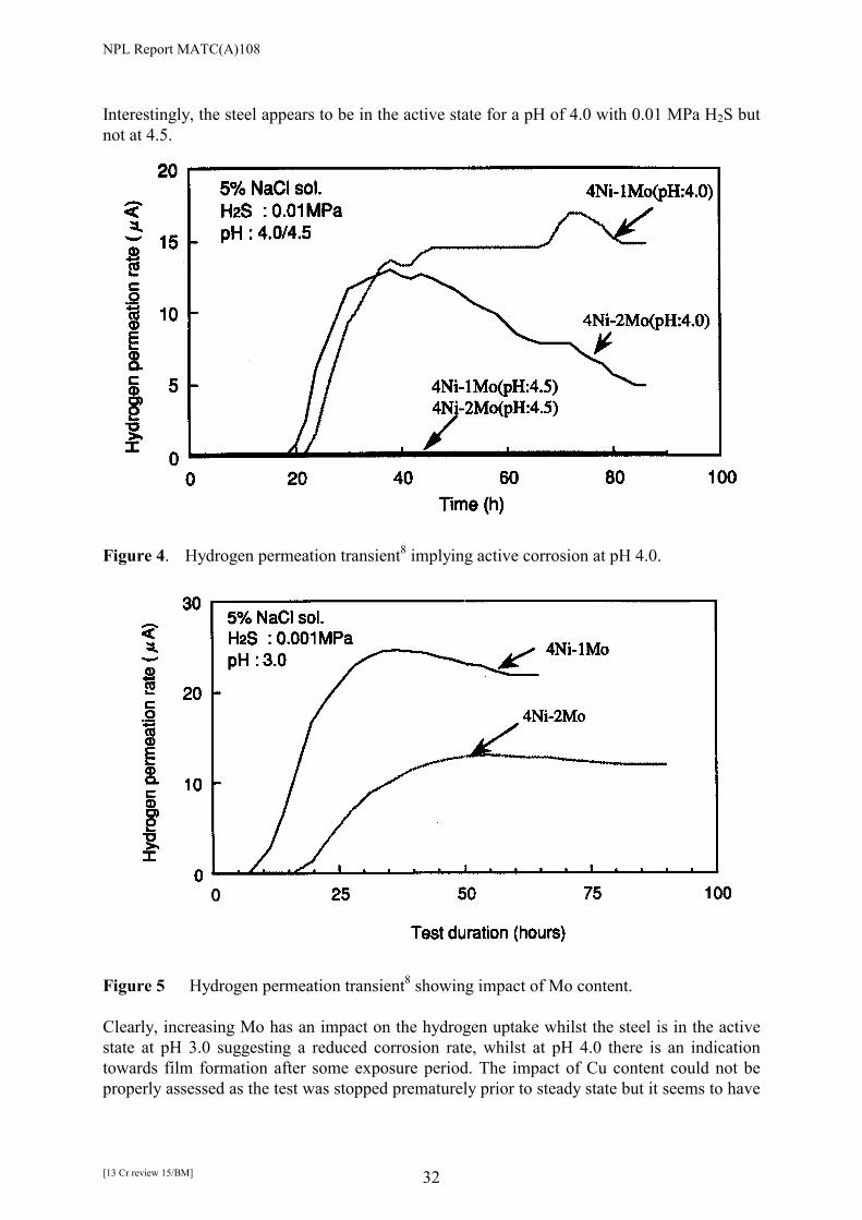
NPL Report MATC(A)108
[13 Cr review 15/BM] 32
Interestingly, the steel appears to be in the active state for a pH of 4.0 with 0.01 MPa H2S but not at 4.5.
Figure 4. Hydrogen permeation transient8 implying active corrosion at pH 4.0.
Figure 5 Hydrogen permeation transient8 showing impact of Mo content. Clearly, increasing Mo has an impact on the hydrogen uptake whilst the steel is in the active state at pH 3.0 suggesting a reduced corrosion rate, whilst at pH 4.0 there is an indication towards film formation after some exposure period. The impact of Cu content could not be properly assessed as the test was stopped prematurely prior to steady state but it seems to have

NPL Report MATC(A)108
[13 Cr review 15/BM] 33
little influence on diffusivity whilst it is claimed that for Mo and Ni there is a discernible effect, although a clear explanation is not given and there is no indication of repeatability. Indeed, the results of Figure 4 for which the rising permeation transients are very similar would suggest minor difference in diffusivities for 2 Mo and 1 Mo-steels. The rising transients from Figure 5 are less comparable but the hydrogen content was clearly different (reflected in the steady permeation current density) and this could have been a factor; in other words, the impact of Mo was to reduce hydrogen entry which also reduces trap occupancy and thus reduced the apparent diffusivity. In further work Kimura et al9 examined the impact on hydrogen permeation of retained austenite in a modified 13 Cr steel. As might be expected the flux decreased with increasing volume fraction of austenite, about a factor of nearly 5 in going to 40 %. The authors interpret this as indicating a reduced hydrogen content but this is an erroneous analysis neglecting the impact of the austenite on the tortuosity of hydrogen diffusion as exemplified for duplex stainless steel by Turnbull and Hutchings10. Kimura et al11 also recorded a very low hydrogen permeation flux when testing modified 13 Cr steel at –1200 mV SCE in artificial seawater. This is consistent with the observation of Turnbull et al and simply reflects the hindrance to hydrogen absorption caused by the oxide film. The diffusion coefficient was about 2x10⁻⁸ cm2s-1 for the cathodically protected steel which compares with the value of 6.0x10⁻⁹ cm2 s-1 estimated from the cathodic charging studies by Turnbull et al2. The extent of hydrogen uptake in modified 13 Cr steels exposed to cathodic protection conditions was measured by Olsen et al12 and the results are shown in Table 4. More details of this testing are given in the next section.
Table 4. Outline of test matrix using constant load (CL) and 4PB specimens. The hydrogen content is expressed as ppm of H2 (after Olsen et al12).
The stressed specimens contained more hydrogen than the unstressed specimens, which was considered due to film rupture whilst the thin specimens contained a higher level than the

NPL Report MATC(A)108
[13 Cr review 15/BM] 34
thicker specimens, which may reflect unsteady charging conditions. The authors do not report the dimensions of the specimens and therefore caution should be exercised in comparing values of hydrogen uptake. There was no effect of pickling of the unstressed specimens in terms of hydrogen uptake. The authors confuse the issue of cathodic currents for protection with hydrogen charging currents. The former is largely determined by oxygen reduction in NaCl and by water reduction when a calcareous scale is formed in seawater, as the scale reduces the oxygen reduction current density. The water reduction kinetics on C-steels are similar for both NaCl and seawater but there is more debate about hydrogen uptake. For 13 Cr steels it is uncertain. The authors also propose use of a coating with a defect. This will reduce significantly local hydrogen content and would be non-conservative for a system with no significant external potential drop in the bulk solution. The authors make an interesting comment about the amount of hydrogen introduced during welding with super duplex filler. It emphasises the need to measure hydrogen content of the steel before considering cathodic charging. Using unstressed specimens at an applied potential of –1350 mV Ag/AgCl in artificial seawater, Hashizume et al13 determined a diffusible hydrogen content (extracted below 600 �C) of 1.5 ppm after 7 days; somewhat less than for Olsen et al but the extraction temperature was less. This should be compared with 6 ppm to 12 ppm when exposed to pH 3.5, 0.0035 MPa H2S under free corrosion conditions; all tests at ambient temperatures. No systematic permeation studies have been made of the effect of H2S on hydrogen uptake under cathodic polarisation to simulate the presence in mud or soil. Turnbull et al3 reported some measurements at high charging current densities of 1 mAcm-2 suggesting an increase in permeation current density of about a factor of 4 in H2S-saturated brine. 3.3 CONCLUSIONS �� The hydrogen uptake, diffusivities and trapping parameters in AISI 410 steel exposed to
H2S-containing acidified brines are well characterised for temperatures between 23 �C and 80 �C.
�� Permeation data have been produced for certain modified 13 Cr steels in H2S-containing
acidified brines at ambient temperature but the method adopted for determining the sub-surface hydrogen content needs verification.
�� The results suggest that incorporation of Mo in the steel reduces the sub-surface hydrogen
content when the steel is in the active state, suggesting repressed dissolution kinetics. Also, the presence of Mo leads to a greater tendency for passivation, as expected from the corrosion studies.
�� Whilst there is clear evidence for irreversible trapping in the AISI 410 steel studies, there
is more ambiguity about the significance of such traps in the modified 13 Cr steels. �� There is little knowledge of the effect of temperature on hydrogen uptake, diffusion
coefficient and trapping of the modified 13 Cr steels in formation or condensate water. Data for cathodically protected steel in seawater for both AISI 410 steel and a modified 13 Cr steel give consistently very low values for the permeation flux but significant uptakes

NPL Report MATC(A)108
[13 Cr review 15/BM] 35
were observed by Olsen et al for stressed specimens. When mechanically testing such material, emphasis should be given to dynamic plastic straining as the oxide film acts as a major barrier to hydrogen entry.
�� There are little data for hydrogen uptake for cathodically protected 13 Cr steels with H2S
present to reflect the action of sulfate reducing bacteria. �� Under cathodic protection in seawater the effects on hydrogen entry of as-welded surface
films and the longer-term impact of calcareous films formed are unknown. �� Coatings on the steel will ensure that the lowest potential (corresponding to the sacrificial
anode value) is achieved at defects, which may seem problematic but previous work at NPL on carbon steels has shown that there is a beneficial effect in that hydrogen absorbed can be effectively delocalised as there will be steep gradients in concentration. Hence there would be less local build up. However, the lower the diffusivity, the less benefit.
�� The use of duplex stainless steel consumables will ensure that the diffusion, solubility and
trapping characteristics of the weld will be different from the adjacent heat affected zone and parent plate. Since quenching of the parent plate reduces significantly the trap site density, as carbon is retained in solid solution, the trap concentration in the heat affected zone of the weld will be different also from that in the parent plate. Although some attempt at prediction of the hydrogen take-up and distribution in a weld has been made, more refinement is required. Comparison of duplex SS consumables and matching 13 Cr consumables would be of value.
3.4 REFERENCES 1. A. Turnbull, M. W. Carroll and D.H. Ferriss, Acta Metall., Vol. 37 (7), 1989, 2039-2046 2. A. Turnbull, M. Saenz de Santa Maria and N.D. Thomas, Corrosion Sci., Vol. 29 (1),
1989, 89-104 3. A. Turnbull, M. W. Carroll, Corrosion Sci., Vol. 30 (6/7), 1990, 667-679. 4. A. Turnbull and A.T. May, Corrosion Sci., Vol. 30 (6/7), 1990, 657-665. 5. T. Boellinghaus, H. Hoffmeister, J. Klemme and H.Alzer, Paper no. 609, Corrosion 99,
NACE Int., Houston, 1999. 6. R. B. Hutchings and A. Turnbull. Corrosion Sci., Vol. 33 (5), 1992, 713-728. 7. T. Boellinghaus and H. Hoffmeister, Paper no. 00141, Corrosion 2000, NACE Int.,
Houston, 2000. 8. M. Kimura, Y. Miyata, Y. Yamane, T. Toyooka and Y. Nakano, Paper No. 22, Corrosion
97, NACE Int, Houston, 1997. 9. M. Kimura, Y. Miyata, T. Toyooka and Y. Kitahaba, Corrosion 2000, Paper No. 00137,
NACE Int., Houston, 2000. 10. A. Turnbull and R.B. Hutchings, "Analysis of hydrogen transport in a two phase alloy".
Mat. Sci. Eng, Vol. A177, 161-171, 1994. 11. M. Kimura, Y. Miyata, T. Toyooka and F. Murase, Paper No. 22, Corrosion 99, NACE
Int, Houston, 1999. 12. S. Olsen, L. Borvik, G. Rorvik and E. Aune, Paper No. 01091, Corrosion 2001, NACE
Int., Houston, 2000. 13. S. Hashimuze, Y. Inohara, Y. Minami and K. Masamura, Paper No. 01085, Corrosion
2001, NACE Int., Houston, 2001.
NPL Report MATC(A)108
[13 Cr review 15/BM] 36
SECTION 4: CRACKING SUSCEPTIBILITY OF MODIFIED 13 Cr STEELS 4.1 INTRODUCTION The domains of stability of the modified 13 Cr martensitic stainless steels in relation to general corrosion, localised corrosion and environment assisted cracking are intertwined to a significant degree. For the internal pipe surface under freely corroding (open circuit conditions) with the passive film intact, chloride stress corrosion cracking and hydrogen embrittlement are usually not significant unless there is significant dynamic plastic strain. Otherwise, cracking is expected to ensue when the passive film is broken down by localised corrosion or when the environment is sufficiently aggressive that the passive film is dissolved and the steel is in the active state. In the latter case, cracking would tend to be by hydrogen embrittlement but in the example of localised corrosion either mechanism could prevail in principle depending on the detailed environmental exposure conditions (solution chemistry and temperature) and material characteristics. Included in this evaluation must be the performance of the weld. Sulphide stress cracking (SSC) is often associated with failure by hydrogen embrittlement but could also embrace chloride stress corrosion cracking in some circumstances where the role of H2S is to facilitate pit initiation and development but the failure mechanism is directly linked to the anodic reaction. In these circumstances, it can often be difficult to isolate the individual failure mechanism. The factors affecting the resistance of the steel are the material composition, strength level, heat treatment (which affects hardness, microstructure and microchemistry), weld consumable, welding procedure, post weld heat treatment, surface films, residual and service stresses, prior deformation, environmental variables including [Cl-], [HCO3
-], CO2 pressure (pCO2), H2S pressure (pH2S), and temperature, and flow conditions. The important requirement is to define a suitable test protocol that includes a meaningful comparative ranking test for the alloys (or environments) and reliable application specific testing. In that context, the issue is the specification and monitoring of laboratory testing requirements including, with the above variables, specimen geometry, loading method, time of exposure, surface preparation. In this overview, a selected sampling of the recent literature on the modified 13 Cr steels has been undertaken with a view to identifying the impact of different service and laboratory test variables, but the main emphasis in the discussion will be on establishing a clear perspective on the best approach to testing. 4.2 FORMATION/CONDENSATE WATERS Coudreuse et al1 conducted tests on welded samples of supermartensitic stainless steels in simulated condensate, 600 ppm Cl- and pH 3.5-3.7, and formation water, 100,000 ppm Cl- and pH 4.5-5.0. Constant load and 4 point bend tests were conducted at 90% yield strength (YS) and 100% YS respectively. Two material grades were studied, one with about 4.5% Ni and 1.5% Mo and the other with 6.5% Ni and 2.5% Mo. A submerged arc welding process was used except for the root pass (plasma welding) but the details of the filler were not given

NPL Report MATC(A)108
[13 Cr review 15/BM] 37
although it would be presumed to be a duplex stainless steel. The pCO2 was 2 MPa (20 bar) and the pH2S was 0.0004 MPa (4 mbar) or 0.004 MPa (40 mbar). Tests were conducted at 20 �C and 90 �C. The main conclusion was that the high chloride level associated with the formation water rendered this environment more severe than the condensate water. The pH was measured after the test so the behaviour is not associated with an upward drift in bulk pH of the condensate water. Bubbling through the solution was maintained but the impact on the flow of solution at the specimen surface was not described; a local surface pH rise is feasible. Also, there was no indication as to whether the specimen in the condensate solution had actively corroded. The implication of these tests would be that an acceptable H2S level cannot be defined out of context of other composition parameters. As expected, regions of high hardness in the HAZ were most vulnerable and a short post weld heat treatment (PWHT) was recommended. In the formation water, the specimens failed more readily at 25 �C than at 90 �C. Coudreuse et al2 conducted a similar set of tests (constant load (90 % YS) and 4pt bend (100% YS ) ) to compare the performance of welds produced with superduplex and matching fillers. The loading was relative to the yield strength of the base material. The environment was a simulated formation water (100,000 ppm Cl-, pH 4.5-5.0, pCO2 2 MPa (20 bar) and pH2S 0.004 MPa (4 mbar), 0.01 MPa (10 mbar) or 0.04 MPa (40 mbar)). Two material grades were studied, one with about 4.5% Ni and 1.5% Mo and the other with 6.5% Ni and 2.5% Mo. The test temperature is not stated but would be assumed to be ambient temperature. For both the base material and the welded specimens, the constant load tests were more severe than the 4 pt bend tests. For example, for one material cracks were observed in constant load tests at 530 MPa but not in 4 pt bend tests at 590 MPa. The authors attribute this to the fact that in constant load tests the stress is constant across the whole section of the specimen whereas in the 4 point bend specimen the stress decreases away from the surface. In the constant load tests, the weld with filler with matching composition was more resistant to cracking than the weld with superduplex filler. The authors suggested that galvanic interaction with the duplex weld metal may have increased the corrosion rate of the 13 Cr steel. An alternative explanation proposed is that strain localisation occurs in the duplex weld metal because its yield strength is lower than that of the 13 Cr steel. This explanation seems unlikely as cracking initiates in the HAZ rather than the weld metal. Kane et al3 conducted slow strain rate and 4pt bent tests on welded centrifugally cast 12Cr-4Ni pipe steel. The weld filler was a 12.5 % Cr, 3.7 Ni, 0.4 Mo, 0.04 C material. The test environments were simulated formation water (40,000 ppm Cl-, 100 ppm HCO3
- with 20,000 ppm Na+ and the balance mainly Ca2+ and Mg2+) and condensate water (1000 ppm Cl-), with 3.8 kPa H2S and 3.8 MPa CO2. Tests were carried out at 167 �C but for the condensate, tests were also conducted at 24 �C. For the bend specimens, there was no indication of the surface finish but it would be presumed to be a machined finish. Slow strain rate (SSR) testing suggested some susceptibility to stress corrosion cracking at 167 �C. None of the 4pt bend specimens failed at 167 �C but all of the specimens failed at 24 �C, including PWHT specimens. Even the base metals exhibited evidence of SSC but to a lesser degree. The authors suggest that the material has a higher susceptibility to SSC than conventional alloys at comparable hardness levels, which they attribute to the Ni content. At 167 �C, the steel was considered to be in the active state and less susceptible to cracking.

NPL Report MATC(A)108
[13 Cr review 15/BM] 38
Various precipitation-hardened martensitic stainless steels were tested by Vitale4 including a 13Cr-4Ni steel. The environment was 100 ppm NaCl. The solution was buffered with acetic acid and sodium acetate (concentrations unspecified). Proof ring tests at 100% YS were conducted at 75 F (24 �C) with a range of H2S and CO2 partial pressures. The strength levels were 683 MPa and 849 MPa. No-fail limits in terms of H2S and pH were identified, viz. 0.7 MPa H2S, pH 3.5 for the lower strength material and for the higher strength, 0.01 MPa H2S at pH 5.5 and 0.001 MPa at pH 4.5. Cooling et al5 established application limits for alloyed 13 Cr steel (1%-2% Mo in a simulated produced water (20 % NaCl) and a simulated condensing water (0.17 % NaCl) with pH values of 3.5 and 4.5 (buffered by a CO2/bicarbonate mix). Uniaxial tensile tests (90% YS) and SSR tests were conducted. In the former the acceptance criteria was no failure and no evidence of cracking at the end of the test. For the SSR tests, the criteria related to the normalised plastic strain to failure with >0.5 considered adequate, 0.35-0.5 as borderline with further testing implied, and <0.35 as inadequate. Tests for SSC resistance were carried out at 20 �C whilst some tests for SCC resistance were conducted at 80 �C in 20% NaCl at pH between 3.5 and 4.5. No evidence of chloride SCC was observed but the tests were carried out without H2S, the presence of which can more readily induce pitting and higher pit growth rates. The results from the SSC tests are represented in Figures 1 and 2 in terms of performance domains. It was noted that the SSC resistance in condensing water was slightly better than in production water, which was considered to be due to a lower propensity towards pitting at the lower chloride level. This is likely when the pH increases above the condition for active corrosion. The conclusion is similar to that of Coudreuse et al1.
Figure 1. SSC domain diagram5 for alloyed 13 Cr steels in high chloride (20%) solutions at 20 �C.

NPL Report MATC(A)108
[13 Cr review 15/BM] 39
Figure 2. SSC domain diagram5 for alloyed 13 Cr steels in low chloride (1000 ppm)
solutions at 20 �C.
The impact of H2S on the SSC resistance of Cr 13 LC, Grade 80, was investigated by Popperling et al6, as illustrated in Figure 3. Failure occurred readily at H2S levels somewhere between 0.003 MPa (0.03 bar) and 0.01 MPa (0.1 bar).
Figure 3. Effect of H2S on the SSC resistance of CR 13 LC (Grade 80) steel in CO2-bearing saline solution6
Rogne and co-workers7 have evaluated the performance of welded super 13Cr steels in NACE solution with 0.1 MPa (1 bar) H2S. The tests were conducted under constant load at room temperature. The results are shown in Figures 4-6. For these test conditions, the steel is in the active state. The authors note that simply testing to 90% of actual YS has to be clarified

NPL Report MATC(A)108
[13 Cr review 15/BM] 40
in relation to welds as the YS could be that of the weld metal, the parent material or a tensile specimen through the weldment. The authors recommend that the effect of test load should be examined as in Figures 4 and 5. PWHT clearly has a beneficial effect.
Figure 4. Effect of heat treatment at 625 �C for 10 mins. for a plasma weld compared with the base material (sub-size specimens); NACE solution, 1 bar (0.1 MPa) H2S (after Rogne et al7).
Figure 5. Effect of heat treatment at 625 �C for 10 mins. for a plasma weld compared with the base material (full-size specimens); NACE solution, 1 bar (0.1 MPa) H2S (after Rogne et al7).

NPL Report MATC(A)108
[13 Cr review 15/BM] 41
Figure 6. SSC resistance domains for welded specimens of super 13 Cr steel in buffered NaCl solution at room temperature. Specimens were PWHT for 3-10 mins at 625 �C. Open points are no-failure; filled points failure (after Rogne et al7).
The results of Figure 6 were based on testing at 90% of YS. Published data based mainly on base material were summarised by Rogne et al as shown in Figure 7 and 8. The data derive from a range of test methods including SSR, 4pt bend and constant load.
Figure 7 SSC resistance domains for alloyed 13 Cr (0.7-1.5 Mo) (after Rogne et al7).
Figure 8 SSC resistance domains for alloyed 13 Cr (2-2.5 Mo) (after Rogne et al7).
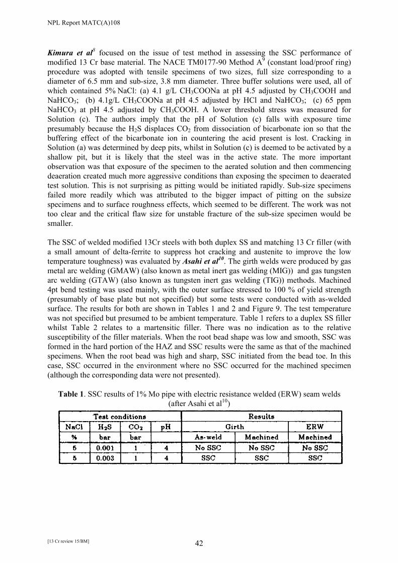
NPL Report MATC(A)108
[13 Cr review 15/BM] 42
Kimura et al8 focused on the issue of test method in assessing the SSC performance of modified 13 Cr base material. The NACE TM0177-90 Method A9 (constant load/proof ring) procedure was adopted with tensile specimens of two sizes, full size corresponding to a diameter of 6.5 mm and sub-size, 3.8 mm diameter. Three buffer solutions were used, all of which contained 5% NaCl: (a) 4.1 g/L CH3COONa at pH 4.5 adjusted by CH3COOH and NaHCO3; (b) 4.1g/L CH3COONa at pH 4.5 adjusted by HCl and NaHCO3; (c) 65 ppm NaHCO3 at pH 4.5 adjusted by CH3COOH. A lower threshold stress was measured for Solution (c). The authors imply that the pH of Solution (c) falls with exposure time presumably because the H2S displaces CO2 from dissociation of bicarbonate ion so that the buffering effect of the bicarbonate ion in countering the acid present is lost. Cracking in Solution (a) was determined by deep pits, whilst in Solution (c) is deemed to be activated by a shallow pit, but it is likely that the steel was in the active state. The more important observation was that exposure of the specimen to the aerated solution and then commencing deaeration created much more aggressive conditions than exposing the specimen to deaerated test solution. This is not surprising as pitting would be initiated rapidly. Sub-size specimens failed more readily which was attributed to the bigger impact of pitting on the subsize specimens and to surface roughness effects, which seemed to be different. The work was not too clear and the critical flaw size for unstable fracture of the sub-size specimen would be smaller. The SSC of welded modified 13Cr steels with both duplex SS and matching 13 Cr filler (with a small amount of delta-ferrite to suppress hot cracking and austenite to improve the low temperature toughness) was evaluated by Asahi et al10. The girth welds were produced by gas metal arc welding (GMAW) (also known as metal inert gas welding (MIG)) and gas tungsten arc welding (GTAW) (also known as tungsten inert gas welding (TIG)) methods. Machined 4pt bend testing was used mainly, with the outer surface stressed to 100 % of yield strength (presumably of base plate but not specified) but some tests were conducted with as-welded surface. The results for both are shown in Tables 1 and 2 and Figure 9. The test temperature was not specified but presumed to be ambient temperature. Table 1 refers to a duplex SS filler whilst Table 2 relates to a martensitic filler. There was no indication as to the relative susceptibility of the filler materials. When the root bead shape was low and smooth, SSC was formed in the hard portion of the HAZ and SSC results were the same as that of the machined specimens. When the root bead was high and sharp, SSC initiated from the bead toe. In this case, SSC occurred in the environment where no SSC occurred for the machined specimen (although the corresponding data were not presented).
Table 1. SSC results of 1% Mo pipe with electric resistance welded (ERW) seam welds (after Asahi et al10)

NPL Report MATC(A)108
[13 Cr review 15/BM] 43
Table 2 SSC results of 2.5% Mo seamless pipe (after Asahi et al10)
Figure 9. Effect of Cl-, pH and H2S on SSC resistance for 4pt bend machined specimens of
2.5% Mo steel welded by GMAW with a martensitic filler10. Kimura et al11 also tested the SSC resistance using a matching weld consumable and compared results with the duplex SS filler. Neither pre-heating nor PWHT were applied. Tests were conducted using constant load as specified by TM0177-90 Method A9 and 4pt bend tests as specified by EFC No. 1712. The test environment for the 4 pt bend test was 10% NaCl with a pH controlled to 4.5 by 0.5% acetic acid and sodium acetate and the solution saturated with 0.004 MPa H2S and CO2 the balance gas. The applied stress for the bend tests was 100% of the actual YS of the base material. For the tensile tests the applied stress was 90% of YS and the environment was 5% NaCl with pH controlled between 3.5 and 4.5 by 0.5% acetic acid and sodium acetate saturated with 0.0008-0.01 MPa H2S and CO2 the balance gas. No cracking was observed for any of the welds tested using the 4 pt bend conditions. The tensile results are shown in Figure 10.

NPL Report MATC(A)108
[13 Cr review 15/BM] 44
Figure 10 Comparison of SSC resistance between duplex and matching consumables (after Kimura et al11)
Pitting occurred in the HAZ of the duplex SS welded joint at pH 4.5 with 0.01 MPa H2S but no pitting or cracking was observed in the matching welded joint under that condition. It is claimed that the SSC resistance for the matching welded joint is a little higher than that of the duplex SS welded joint but there is only a marginal difference in Figure 10. The maximum hardness of the matching welded joint was nearly equal to that of the duplex SS welded joint. Routine SSC testing was carried out by Linne et al13 on 95 ksi grade and 110 grade super martensitic stainless steel (for OCTG application) using NACE and EFC standard solutions and with some well simulations, in all cases with NaCl �50 g/L . No failure was observed for pH2S values of 1.5 psi (0.01 MPa). Kimura et al14 suggest a critical partial pressure of H2S of more than 0.005 MPa for cracking of the 2% Mo steel at pH 3.5. Test were conducted as per NACE TM0177-90 Method A9 (constant load/proof ring) with 5 %NaCl and varying pH and H2S values with CO2 the balance gas. Specimens were loaded to 100 % of specified minimum yield strength (SMYS). The effects of alloy composition and of yield strength are indicated in Figures 11-14.
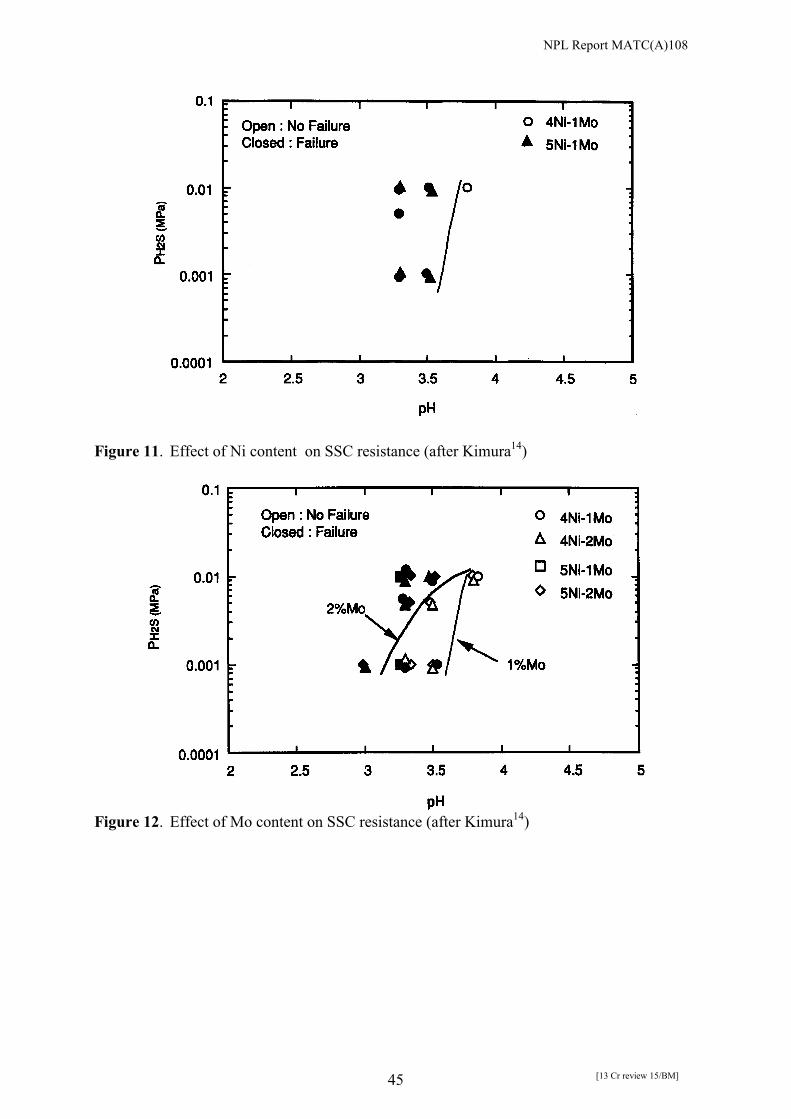
NPL Report MATC(A)108
[13 Cr review 15/BM] 45
Figure 11. Effect of Ni content on SSC resistance (after Kimura14)
Figure 12. Effect of Mo content on SSC resistance (after Kimura14)

NPL Report MATC(A)108
[13 Cr review 15/BM] 46
Figure 13. Effect of Cu content on SSC resistance (after Kimura14)
Figure 14. Effect of yield strength on SSC resistance (after Kimura14) For the range tested, there was no effect of Ni in the very limited range tested, a notable effect of Mo insofar as the 2% Mo steel can tolerate a lower pH for the same H2S level provided pH2S is less than 0.01 MPa, and no effect of Cu. The C95 grade had somewhat better performance than the higher strength alloy. In a review article, Cayard and Kane15 summarised SSC data for both conventional (SMYS 550-655 MPa) and modified 13 Cr steels (SMYS 550-760 MPa). The results are shown in the SSC domain diagram of Figure 15 where the domains are non-sour service region, transition region and sour-service region for carbon steels based on EFC 16. The data represent tests

NPL Report MATC(A)108
[13 Cr review 15/BM] 47
conducted at 25 �C and stressed from 80-100% of SMYS in brine solutions ranging from 30,000 ppm to 60,000 ppm Cl-. The modified steels do appear to offer improved resistance in the nominally sour-service domain.
Figure 15. SSC performance of conventional and modified 13 Cr steels (after Cayard and Kane15)
Sakamoto et al16 undertook a detailed study of the impact of environmental variables (temperature, pH2S, pH and [Cl-]) on SSC for modified 13 Cr steels at two strength levels, 618 MPa and 814 MPa, using notched 4pt bend tests with the specimens loaded to 100% of YS. The balancing gas in all cases was CO2 and the pH was adjusted with bicarbonate. The pH values quoted are calculated values. SSC pH-pH2S domain diagrams were established and the boundaries between cracking and no-cracking identified for varying temperature and chloride concentrations. The data at temperatures between 25 �C and at 125 �C are shown in Figure 16-19. At 125 �C, the steel is in the active state but the temperature is too high for significant hydrogen embrittlement.

NPL Report MATC(A)108
[13 Cr review 15/BM] 48
Figure 16. V-notched 4pt bend test results in 5 % NaCl at 25 �C (after Sakamoto et al16).
Figure 17. V-notched 4pt bend test results in 5 % NaCl at 50 �C (after Sakamoto et al16).

NPL Report MATC(A)108
[13 Cr review 15/BM] 49
Figure 18. V-notched 4pt bend test results in 5 % NaCl at 80 �C (after Sakamoto et al16).
Figure 19. V-notched 4pt bend test results in 5 % NaCl at 125 �C (after Sakamoto et al16).
The effect of temperature on the critical pH2S for cracking at pH 4.5 is shown in Figure 20 and shows a progressive increase required as the temperature increases for the lower strength steel but with an initial levelling off at the lower temperature for the high strength steel.

NPL Report MATC(A)108
[13 Cr review 15/BM] 50
Figure 20. Effect of temperature on critical pH2S for cracking or pitting in 5% NaCl at
pH 4.5 (after Sakamoto et al16). The impact of chloride at ambient temperature is shown in Figure 21 but the data are too sparse in the low chloride region to establish the critical value. At this pH value, pitting is the key process required for hydrogen entry. Despite using notched specimens, there was no discussion in the paper of the significance of the notch.
Figure 21. Effect of NaCl concentration on critical pH2S for cracking or pitting at 25 �C and
pH 4.5 (after Sakamoto et al16). Scoppio et al17 studied a number of super 13 Cr steels of varying strength level designed for OCTG applications over a range of temperatures and environmental conditions using the

NPL Report MATC(A)108
[13 Cr review 15/BM] 51
NACE TM-177-90 Method A (proof ring/constant load) with a modified solution and using SSR testing. It was essentially a data gathering exercise to establish critical conditions for cracking but the authors note the general agreement between the two different test methods. Using SSR testing at 10-6 s-1 and the assumption of a pass when the normalised RA is greater than or equal to 0.9, Boellinghaus et al18 established domains diagrams (Figures 22 and 23) for two 13 Cr steels in the as-delivered and quenched state, the latter to simulate the HAZ of a weld. Tests were conducted in NACE TM0177-96 standard test solution9 but with the pH adjusted with NaOH. Material A had 0.025 C, 3.85Ni with 0.96 Mo and a 0.2% proof stress of 750 MPa, whilst Steel B had 0.008C, 6.47Ni and 2.44 Mo (0.2% proof stress of 710 MPa).
(a) (b) Figure 22. SSC domain diagram for modified 13 Cr steel (A) in as-delivered (a) and
quenched state (b) (after Boellinghaus et al18).
(a) (b) Figure 23. SSC domain diagram for modified 13 Cr steel (B) in as-delivered (a) and
quenched state (b) (after Boellinghaus et al18).

NPL Report MATC(A)108
[13 Cr review 15/BM] 52
The higher alloyed steel performed better as expected both in the as-delivered and quenched state, which would appear to be related mainly to the increase resistance to pitting corrosion but with an indication of greater film stability at the lower pH end (i.e. it would be inferred to remain passive down to lower pH values). The performance of radial friction welds has been investigated by Swidzinski et al19 with both 25% Cr duplex and matching filler. 4 pt bends tests to 90% of measured �0.2 (650 MPa) of the base material were conducted with the weld centred. The environment consisted of 162,450 ppm chloride, with 0.23% H2S (2.3 x 10⁻⁴ MPa) and 99.77 mol % (0.1 MPa) CO2 (pH 3.9) for tests at 25 �C at 1 atmos/ total pressure, and 30 ppm H2S, 3.98 mol% for CO2 at total pressure of 200 atmos (about 20 MPa) with temperatures of 90 �C (pH 5.3) and 150 �C (pH 4.6). No cracking or pitting was observed but some relaxation of the specimens was evident after testing at 150 �C. The full ring test was conducted at an applied load of 650 MPa in NACE TM-01-77 solution at 25 �C. Again no cracking or pitting was observed. In recent work, Hashizume et al20 suggested an optimum temperature of 650 �C for PWHT of matching welds and noted a reduction in hardness in both the weld metal and the HAZ following PWHT. No SSC was observed when testing at ambient temperature using simulated condensate water (0.001 MPa H2S, 0.099MPa CO2, 1 g/L NaCl, 0.4 g/L CH3COONa at pH 3.6) and formation water (0.001 MPa H2S, 0.099MPa CO2, 38.9 g/L NaCl, 0.4 g/L CH3COONa at pH 3.6). Rogne et al21 highlighted a number of important observations on the cracking resistance of welded 13 Cr steels. Firstly, the 13 Cr steels studied showed an increased yield strength with temperature (but a decreased tensile strength), reflective probably of transformation of retained austenite to martensite. In simulated condensate and formation waters at ambient temperatures with about 0.2 kPa H2S and 2 MPa CO2, no cracking of either the seam or girth weld (super-duplex SS filler) was observed. However, at 110 �C, intergranular corrosion and cracking of the as-welded root girth weld was obtained which was associated with sensitisation of prior-austenite grain boundaries (precipitation of chromium carbides) close to the fusion line. The cracks extended to mid-thickness of the 4 pt bend specimens. Post weld heat treatment at 650 �C for 5 mins. eliminated the problem, but whether this was due to diffusion of Cr to the depleted zone or some other effect (e.g. stress relief) was not established. Interestingly, testing of machined specimens indicated no cracking despite the similar microstructure. This would suggest that the root surface film was important in moving the potential into a regime for cracking or there was some pre-existing defect or notch. Applying a small galvanostatic current to accelerate the transformation of the as-welded surface to one considered more typical of service conditions also gave cracking. In pitting and crevice tests, cracking was noted in the HAZ of the root girth weld implying some residual stress. Boellinghaus et al22 conducted tests on instrumented full scale pipes, a key feature being to avoid the partial residual stress relaxation inevitable in preparing small laboratory specimens. The internal surface was exposed at ambient temperature for about 3 weeks to a simulated formation water with 0.45 MPa CO2 and 0.45 kPa H2S and a pH of 4.7. The pipes were then subjected to slow strain rate testing transverse to the weld at a strain rate of 1.7x10⁻⁵ s-1 but with hold periods at 70% �0.2, 100% �0.2, and at 3% and 5% strain measured at the weld metal of the circumferential welds. At 5% strain, failure occurred. Cracking initiated in the hardened

NPL Report MATC(A)108
[13 Cr review 15/BM] 53
HAZ and not in the undermatching DSS weld metal nor in the matching super-martensitic stainless steel weld metal. In both types of weld the cracks propagated to a certain depth in the HAZ before turning towards the weld metal. The authors suggest that cracking occurs as a result of general hydrogen ingress and also pitting. In the former case they used models of general hydrogen uptake, but it is questionable whether such general uptake to a significant level is feasible at this pH, as the steel is in the passive state. Hydrogen uptake then usually occurs with dynamic straining or with pitting. Olsen et al23 has raised a number of issues related to qualifying 13 Cr materials for sour service. The materials appear to be most sensitive to cracking at ambient temperature as the passive film thickens with temperature. The HAZ is most sensitive to cracking about 0.1 mm from the fusion line. In environments where cracking initiates from pits, Olsen considers that the pH of the bulk environment may be insignificant. Specimens with machined surfaces are more susceptible to cracking than specimens with the oxide film intact. He reports that PWHT can reduce the hardness in the HAZ by 30 units. When testing welds with a softer superduplex filler, Olsen loads to 100% YS of the weld metal, rather than 100% YS of parent material as recommended in EFC 1712. The actual strength of the weld metal is measured using a tensile specimen machined from the weld. He reports significant variation in the hardness through the weld. In general, constant load tests are more severe than 4 point bend tests, with more pitting occurring on constant load (CL) specimens than on 4 pt bend specimens. Olsen attributes this to the fact that the surface of the CL specimen is machined whereas the 4 pt bend specimen retains its original surface. He suggests that machined surfaces of 4 pt bend specimens should be coated to prevent attack at these surfaces. This could be problematic as crevice corrosion may occur under the coating. He recommends using full size (as opposed to sub-size) specimens for CL tests to reduce the effect of weld defects on the stress concentration. In fact, the stress concentration at a weld defect will be independent of the size of the specimen. The critical flaw size for unstable fracture will be smaller for a smaller specimen and this will result in sub-size specimens fracturing more rapidly in tests. 4.3 CATHODIC PROTECTION Rogne et al7 evaluated the performance of 13 Cr base material under cathodic protection with and without H2S (associated with sulfate-reducing bacteria). Testing was undertaken using SSR, with some discussion on the relative merits of relative time to failure and reduction in area (%RA)7. Clearly, it depends on whether failure occurs significantly after UTS or before, with %RA being not so sensitive to tests conditions in the latter case. The authors highlight the problem of establishing criteria for service based on SSR data but note that cracking susceptibility was increased with just 47 ppm of H2S in solution. The resistance to cracking of super 13 Cr base material under cathodic protection was investigated also by Hashizume et al24 using uniaxial loading at an applied potential of -1350 mV Ag/AgCl in artificial seawater. No failure was observed for any of the materials tested. The diffusible hydrogen content (extracted below 600 �C) was measured as 1.5 ppm after 7 days. This should be compared with 6 ppm to 12 ppm when exposed to pH 3.5, 0.0035 MPa H2S; all tests at ambient temperatures. For these cases, failure of the 839 MPa YS steel occurred but for the lower strength steel of 627 MPa YS, failure depended on alloy composition with the alloy with higher Cr and Mo showing greater resistance despite similar hydrogen uptake.

NPL Report MATC(A)108
[13 Cr review 15/BM] 54
Asahi10 reported that 4 point bend tests under cathodic protection conditions at -1194 mV SCE gave no cracking after two months for girth welds and seam welds in a 1% Mo material and girth welds in a 2.5% Mo material. Specimens were tested both with a machined surface and with the original surface in tact. Kimura et al11 did not observe cracking in 4 pt bend tests under cathodic overprotection conditions, -1600 mV SCE for welds of a 12Cr-5Ni-2Mo steel, produced with both duplex and matching fillers. Cathodic protection studies of super 13 Cr steel (6.5% Ni, 2.5%Mo) welded (GMAW) with matching filler have been conducted by Olsen et al25 using constant load specimens tested at 90% and 100% actual YS and 4pt bend specimens stressed to 100% YS. The actual YS was measured for a cross weld tensile specimen to be 759 MPa. The electrolyte was 3 % NaCl buffered with 0.2 g/L NaHCO3. The test matrix is summarised in Table 3 together with the measured hydrogen uptake (hot extraction at 950 �C). No reference value for the hydrogen uptake was given corresponding to uncharged conditions. The results of the constant load and 4 point bend tests are shown in Table 4.
Table 3. Outline of test matrix. The hydrogen content is expressed as ppm of H2 (after Olsen et al25).

NPL Report MATC(A)108
[13 Cr review 15/BM] 55
Table 4. Results from constant load and 4pt bend tests (after Olsen et al25)
Olsen et al reported that both constant load specimens stressed to 90% of actual YS at -1050 mV SCE cracked but only one of the two stressed to 100% of actual YS failed. For the specimens with PWHT none failed when stressed to 90% of actual YS. None of the 4pt bend specimens failed when stressed to 100% of actual YS. The cracking in the constant load specimens initiated in the weld metal and there was no evidence of cracking in the HAZ in any of the specimens. PWHT did not affect the hardness of the weld metal although the hardness in the HAZ and the sensitivity to cracking were reduced. The authors conclude that since the HAZ should be independent of the filler then the super duplex filler will have better resistance to hydrogen embrittlement as the weld metal hardness is lower and the microstructure different. Dynamic straining tests at 10-6 s-1 on specimens precharged for 4 weeks gave rise to cracking at 1.5%-2.0% total strain, which is perceived to be higher than the design value of 0.5%25. Rogne7 reported that there was no effect of pre-charging on the time to failure of a 12 Cr-6Ni-2Mo steel in SSR tests at 10-6 s-1. However, the charging time and the test conditions were not reported. Pourbaix26 discussed the issue of cathodic protection potential for 13 Cr flowlines exposed to seawater with the appropriate conclusion that it is sufficient to reduce the potential to a value at which localised attack cannot proceed rather than drop the potential down close to sacrificial anode potential where there is a potential risk of hydrogen embrittlement. He suggests a potential of –400 mV SCE would be sufficient but methods of controlling that value need to be investigated. Swidzinski et al19 evaluated the performance of radial friction welds with both 25% Cr duplex and matching fillers. The full ring test was conducted at an applied load of 650 MPa (90% YS) in clean natural seawater at a an applied potential of –1100 mV SCE. No cracking was observed.

NPL Report MATC(A)108
[13 Cr review 15/BM] 56
4.4 DISCUSSION 4.3.1 Testing Loading method Cracking of the super 13 Cr steels is very unlikely under cathodic protection unless there is significant plastic strain as otherwise the hydrogen uptake is too low because of the poor ‘transparency’ to hydrogen of the passive film, consistent with the behaviour of duplex stainless steels for example. However, there is a possible sensitivity to the test method used. With 4 point bend testing at 100% YS, no cracking of welds, with either duplex SS filler or matching 13 Cr filler, was observed by Olsen et al, Kimura et al and Asahi et al over a range of potentials including overprotection potentials. This included tests by Asahi on as-welded and machined specimens, without PWHT. In contrast, Olsen et al25 noted a significantly higher hydrogen uptake and observed failure of specimens at –1050 mV SCE under constant load at both 90% and 100% of actual YS. In this case the hardness was 350 HV5 and cracking occurred in the weld (matching filler). Olsen et al23 and Coudreuse2 reported that for tests in formation waters constant load tests appeared to be more severe than 4 point bend tests. EFC 1712 compares the amount of creep that will occur after loading in constant load and constant displacement tests, Figure 24.
Figure 24. (i) Effect of strain rate on the proof stress of a superduplex stainless steel at 24 �C12.
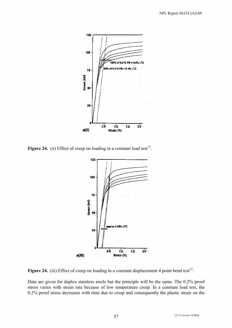
NPL Report MATC(A)108
[13 Cr review 15/BM] 57
Figure 24. (ii) Effect of creep on loading in a constant load test12.
Figure 24. (iii) Effect of creep on loading in a constant displacement 4 point bend test12. Data are given for duplex stainless steels but the principle will be the same. The 0.2% proof stress varies with strain rate because of low temperature creep. In a constant load test, the 0.2% proof stress decreases with time due to creep and consequently the plastic strain on the

NPL Report MATC(A)108
[13 Cr review 15/BM] 58
specimen increases and the specimen is subject to dynamic straining. In a constant displacement test, the displacement on loading consists of elastic strain (proportional to the stress) and 0.2% plastic strain. The stress on the specimen will decrease with time due to creep. This will reduce the elastic strain and the plastic strain will therefore be increased to maintain constant total strain. However, the data indicate that the degree of plastic straining is much less for a constant displacement than for a constant load test, which would tend to make the latter a more severe test. The EFC document12 tries to address this imbalance by stressing constant load tests to 90% of the 0.2% proof stress and constant displacement tests to 100% of the 0.2% proof stress. However, data from EFC 17 indicate that creep may not be a significant factor in testing 13 Cr steels as the extent of creep is small compared with a duplex steel, Figure 25.

NPL Report MATC(A)108
[13 Cr review 15/BM] 59
Figure 25. Comparison of extent of creep at ambient temperature for (i) 22 Cr duplex at 0.2%
proof stress (537 MPa), (ii) API 13 Cr 80 at 0.2% proof stress (599 MPa), (iii) API 13 Cr 80 at different stress levels12.
There remains the question as to which test method is most appropriate. A 4 point bend test has the advantage that tests in the as-welded or machined conditions can be used with the latter machined close to the original surface. The original surface finish cannot be retained for a cylindrical tensile specimen but it would be possible to conduct constant load tests using flat parallel-sided specimens with the original surface intact. The disadvantage of 4 point bend tests comes when the region of susceptibility is subsurface (local hard spot or and/or region of tensile residual stress) but in the 4 point bend specimen the stress at that location has fallen below the threshold for cracking. This will be a function of specimen thickness, which should be as thick as is practical, Figure 26. However, within the limits of specimen thickness, there is no reason that the bend specimen cannot be made such that its machined surface is at a depth below the original surface, if that is where the most sensitive region is identified from microhardness scanning.

NPL Report MATC(A)108
[13 Cr review 15/BM] 60
Figure 26. Distribution of stress through the thickness of a 4 point bend specimen, where σ is
stress and σs is the stress at the outer surface. Constant load tests may be more reliable (although more expensive) because the stress is well-defined throughout the specimen, even for a welded specimen. It is inevitable that for a welded 4 point bend specimen the strain in the outer surface will not be uniform and that the distribution will depend on the area fraction of the weld between the inner supporting rods. EFC 1712 recommends that the load applied should be relative to the yield strength of the parent material and this should be measured by strain gauging the parent plate adjacent to the weld. In a 4 point bend test, this would result in yielding of the weld metal in an undermatched weld, whilst the stresses in an overmatched weld would be lower than those in the parent material due to strain localisation in the lower strength material. If the specimens were loaded according to the equations in ASTM G3927 which assume homogenous elastic material, the weld metal would yield in an undermatched weld, whilst the stresses in an overmatching weld would be higher than in the parent material. Yielding of the weld metal may also occur in a constant load test with an undermatched weld. Olsen eliminates this uncertainty by measuring the yield strength of the weld metal and applying the load appropriately23. This would results in a lower load on the parent material in an undermatched weld. In relation to plastic strain, an occasional pipe movement in service is to be expected. This will induce some plastic strain and laboratory tests should account for that. Indeed, it may be envisaged that the test should involve a slow cyclic plastic strain but distinguished from the current Shell test by inducing strains beyond nominal yield. The use of the slow strain rate as a ranking test is satisfactory but assigning acceptance criteria is concerning because of the sensitivity of cracking to strain rate. Based on cumulative experience, it may be possible to define some criteria but there is no existing agreement. The slow strain rate test may not be suitable for weldments as the strain may be localised in the lowest strength material. Failure may occur in these regions rather than in the harder regions that are usually more susceptible to stress corrosion cracking.

NPL Report MATC(A)108
[13 Cr review 15/BM] 61
Fowler and Himeman28 gave emphasis to the value of full ring tests because of retention of key factors such as residual stress induced by pipe manufacture and welding and the more ready identification of stress oriented hydrogen induced cracking (SOHIC). Boellinghaus et al22 also conducted tests on instrumented full scale pipes, a key feature being to avoid the partial residual stress relaxation inevitable in preparing small laboratory specimens. Such tests are of course more representative but non-trivial. Environmental factors Kimura et al8 used three buffer solutions all of which contained 5% NaCl: (a) 4.1g/L CH3COONa at pH 4.5 adjusted by CH3COOH and NaHCO3; (b) 4.1g/L CH3COONa at pH 4.5 adjusted by HCl and NaHCO3; (c) 65 ppm NaHCO3 at pH 4.5 adjusted by CH3COOH. Unusual observations were reported including a decrease in pH of Solution (c) with time as H2S was bubbled into the solution, thereby giving a lower threshold stress. This is presumably because the H2S displaces CO2 from dissociation of bicarbonate ion so that the buffering effect of the bicarbonate ion in countering the acid present is lost. It emphasises the need for pH measurement before and after testing, and consideration of the effectiveness of buffering. Where pH measurement after testing is made, care should be taken to avoid exposure to the atmosphere as this will quickly modify the pH of unbuffered solutions. Exposure of the specimen to the aerated solution and then commencing deaeration created much more aggressive conditions than exposing the specimen to deaerated test solution. This is not surprising as pitting would be initiated rapidly. At the STG 32 committee meeting at Corrosion 2002 to revise the TM0177-96 document9, Test solution C was altered. Specifically, emphasis is now on the use of the lower concentration of acetic acid (0.4 g/L) for buffering but the control of pH is such that a drift of no more than 0.2 pH units is allowed during the test. Test duration Laboratory tests are inherently short, typically 30 days or less. It is assumed that this is sufficient to indicate the likelihood of cracking. The key time–dependent factors are the corrosion potential, and its impact on pitting, and the time for any hydrogen generated on a surface to get to a local ‘hot-spot’ should that exist sub-surface. In the latter case, this could be a combination of hardness, residual stress and or microstructural feature. Scanning hardness measurements and microstructural analysis prior to testing should be carried out. Specimen size Constant load tensile tests comparing sub-size and full size specimens, conducted by Kimura et al8, indicated more ready failure of the former which was attributed to the bigger impact of pitting on the subsize specimens and to surface roughness effects, which seemed to be different. Failure appeared to be defined as fracture of the specimen and it is not clear from the paper whether the extent of pitting and crack initiation differed for the two specimen sizes. Clearly the critical flaw size for unstable fracture of the sub-size specimen would be smaller for the sub-size specimen. Olsen23 recommended using full size specimens for constant load testing as the impact of weld defects is enhanced for sub-size specimens but he did not present the data in the paper.

NPL Report MATC(A)108
[13 Cr review 15/BM] 62
The stress varies through the thickness of a 4 point bend specimen (see Figure 26) and therefore the specimen should be as thick as possible if the sensitive regions lie below the surface. Surface condition The condition of the surface of the specimen is important in determining the resistance to cracking. The nature of the oxide film on the surface will influence the pitting susceptibility and the extent of hydrogen uptake. In addition, there may be stress concentrators on an as-received welded surface. Olsen reported that the original weld surface was more resistant to pitting and subsequent cracking than a machined surface. Olsen and Enerhaug29 suggested there may be a requirement to pre-expose as-welded specimens in more benign environments before testing in order to pre-condition the surface to be closer to service conditions. It may be recalled, from the work of Asahi et al10, that the propensity for failure of the as-welded material was affected by the root bead profile. Indeed for hydrogen embrittlement, cracking is most likely where there is local plastic strain and a local hydrostatic stress component. This is more likely at the toe of a weld. Correspondingly, if testing machined specimens, there seems little point in doing this without notching the specimen if trying to reflect possible behaviour of welds. Consideration would have to be taken as to the location of the notch with respect to the weld. Procedural issues There is considerable variability in the approach to deaerating the solutions with respect to whether this is done after or before specimen exposure. For many cases, this is not a factor but it is argued by Olsen and Enerhaug29 that exposure of as-welded super 13 Cr steels to the oxygen containing media, albeit transiently, may alter the properties of the surface film. The more fundamental issue is the procedure that should be used to pre-expose the as-welded material to simulate the surface transformations that occur in service. This needs further research. The acceptable oxygen level upon deaeration is less clear with values between 1 ppb and 10 ppb being common. There is no definitive evidence as to the critical oxygen level below which no effect is observed but clearly, this would be environment sensitive. There are some differences in the procedure for loading 4 point bend specimens. EFC 1712 states that martensitic stainless steels generally show elastic behaviour close to 0.2% proof stress and therefore the equations given in the ASTM25 and ISO30 standards can be used for stressing homogenous specimens of these materials, although it is recommended to check the calculations using strain gauges. However, tests at NPL indicate that there is a discrepancy between the displacement calculated on the basis of elastic behaviour and that measured by strain gauging the specimen. Even when strain gauges are used, differences arise depending on whether the reference data was produced using tensile or flexural (4 point bend ) data. The total (elastic + plastic) strain equivalent to the 0.2% proof stress is calculated from the reference data and the specimen is loaded to give the same total strain. However, tests at NPL have demonstrated that the total strain on a 4 point bend specimen nominally loaded to 0.1%
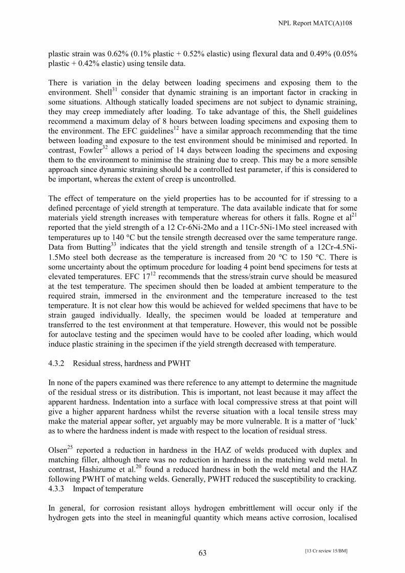
NPL Report MATC(A)108
[13 Cr review 15/BM] 63
plastic strain was 0.62% (0.1% plastic + 0.52% elastic) using flexural data and 0.49% (0.05% plastic + 0.42% elastic) using tensile data. There is variation in the delay between loading specimens and exposing them to the environment. Shell31 consider that dynamic straining is an important factor in cracking in some situations. Although statically loaded specimens are not subject to dynamic straining, they may creep immediately after loading. To take advantage of this, the Shell guidelines recommend a maximum delay of 8 hours between loading specimens and exposing them to the environment. The EFC guidelines12 have a similar approach recommending that the time between loading and exposure to the test environment should be minimised and reported. In contrast, Fowler32 allows a period of 14 days between loading the specimens and exposing them to the environment to minimise the straining due to creep. This may be a more sensible approach since dynamic straining should be a controlled test parameter, if this is considered to be important, whereas the extent of creep is uncontrolled. The effect of temperature on the yield properties has to be accounted for if stressing to a defined percentage of yield strength at temperature. The data available indicate that for some materials yield strength increases with temperature whereas for others it falls. Rogne et al21 reported that the yield strength of a 12 Cr-6Ni-2Mo and a 11Cr-5Ni-1Mo steel increased with temperatures up to 140 �C but the tensile strength decreased over the same temperature range. Data from Butting33 indicates that the yield strength and tensile strength of a 12Cr-4.5Ni-1.5Mo steel both decrease as the temperature is increased from 20 �C to 150 �C. There is some uncertainty about the optimum procedure for loading 4 point bend specimens for tests at elevated temperatures. EFC 1712 recommends that the stress/strain curve should be measured at the test temperature. The specimen should then be loaded at ambient temperature to the required strain, immersed in the environment and the temperature increased to the test temperature. It is not clear how this would be achieved for welded specimens that have to be strain gauged individually. Ideally, the specimen would be loaded at temperature and transferred to the test environment at that temperature. However, this would not be possible for autoclave testing and the specimen would have to be cooled after loading, which would induce plastic straining in the specimen if the yield strength decreased with temperature. 4.3.2 Residual stress, hardness and PWHT In none of the papers examined was there reference to any attempt to determine the magnitude of the residual stress or its distribution. This is important, not least because it may affect the apparent hardness. Indentation into a surface with local compressive stress at that point will give a higher apparent hardness whilst the reverse situation with a local tensile stress may make the material appear softer, yet arguably may be more vulnerable. It is a matter of ‘luck’ as to where the hardness indent is made with respect to the location of residual stress. Olsen25 reported a reduction in hardness in the HAZ of welds produced with duplex and matching filler, although there was no reduction in hardness in the matching weld metal. In contrast, Hashizume et al.20 found a reduced hardness in both the weld metal and the HAZ following PWHT of matching welds. Generally, PWHT reduced the susceptibility to cracking. 4.3.3 Impact of temperature In general, for corrosion resistant alloys hydrogen embrittlement will occur only if the hydrogen gets into the steel in meaningful quantity which means active corrosion, localised

NPL Report MATC(A)108
[13 Cr review 15/BM] 64
corrosion, or plastic straining to rupture the surface film. It is important to distinguish the difference between cracking originating from localised corrosion from that associated with active corrosion because of the different temperature dependence. In the case of active corrosion, the sensitivity to hydrogen embrittlement would tend to diminish with increasing temperature. Although the lattice solubility of hydrogen increases with temperature and the corrosion rate increases (generating more hydrogen), the tendency for trapping of hydrogen decreases and it is the concentration of trapped hydrogen that determines cracking. The situation would be similar when hydrogen entry is associated with rupture of the passive film. In less aggressive environments, for which localised corrosion is the precursor to cracking (dissolving the film barrier to hydrogen entry and lowering the local pH) increasing the temperature may be necessary to initiate localised corrosion. Thus, susceptibility to cracking can be perceived to increase with increasing temperature, then peak and decrease with further increase in temperature. These are general statements that might be made about a passive system such as a duplex stainless steel for example. For 13 Cr steels the behaviour is complicated. The growth rate of pits can have an inverse dependence on temperature when H2S is present (see Case et al in Section 1) whilst it has been suggested also that the protectiveness of the as-welded oxide in simulated formation water is lowest near ambient temperature (Enerhaug et al in Section 1). Hence, simple perceptions may not readily apply for this material. The results of Sakamoto16 (Figure 20) would suggest that cracking susceptibility progressively decreases with increase in temperature. Coudreuse1 and Kane3 also reported a decrease in cracking susceptibility with temperature. However, more extensive testing for a range of chloride levels would be of value to confirm that tests near room temperature or below are indeed the most conservative in relation to testing for SSC resistance. The most notable result was that of Rogne et al21 indicating intergranular stress corrosion cracking of a root girth weld at 110 �C due to sensitisation. 4.3.4 Chloride concentration The evidence from the work of Coudreuse et al1 and from Cooling et al5 is that the high chloride associated with formation waters increases susceptibility in the domain where pitting is the precursor to cracking. 4.3.5 Matching vs duplex SS filler In general, the weld metal in a duplex weld will be less susceptible to cracking than with a matching filler due to the lower yield strength. However, cracking usually occurs in the HAZ. Kimura et al11 observed little difference in SSC susceptibility between duplex and matching weld filler in a simulated formation water although he did report pitting in the HAZ of the duplex SS weld when no pitting was observed in the matching weld. Coudreuse2 made the observation that the HAZ of a duplex weld is more susceptible to pitting than a matching weld. He reported that welds with matching filler had better resistance to cracking than welds with duplex filler. There is the possibility of galvanic interaction between duplex weld metal and 13 Cr parent metal although the area ratio of the duplex to the 13 Cr steel is small. However, it does appear

NPL Report MATC(A)108
[13 Cr review 15/BM] 65
that the duplex is able to raise the potential locally above the pitting potential and thus to induce pitting in the HAZ in conditions for which the parent plate on its own or with a matching consumable are resistant to pitting. There would also be the possibility of enhanced pit growth kinetics in the early stages of pit development with a duplex SS consumable. This would be expected to reduce the resistance of the duplex weld to cracking as pitting is a precursor to cracking. Another factor contributing to the pitting observed with the duplex weld may be differences in the microstructure of the HAZ. There is a concern about the impact of the weld metal material on the distribution of hydrogen in the HAZ. 4.5 CONCLUSIONS �� Resolution of the most effective loading method for welded specimens is required which
accounts for the surface state but reconciled with the possibility that the most susceptible region may be sub-surface.
�� Cyclic dynamic plastic straining should be adopted for cathodically protected specimens
of welds. If not testing the weld surface directly, notching of machined specimens should be considered.
�� Whilst coatings may be applied in service, it would be prudent to test without coating but
with the proviso that the tests are done in a way which minimises the potential drop in the test system as a defect at a coating would likely experience sacrificial anode potentials.
�� Some measure of the relationship between residual stress, hardness and PWHT should be
established. �� For 13 Cr steels, increasing the temperature at pH values where pitting is the precursor to
cracking appears to decrease susceptibility to SSC. This may be associated with the oxide film becoming less protective as the temperature increases but should be confirmed.
�� Whilst a matching weld filler would be expected to be more susceptible to hydrogen
embrittlement because of a higher hardness of the weld metal relative to the duplex SS filler, there is limited evidence to suggest that welds with matching fillers are more resistant to cracking than welds with duplex fillers. The HAZ of a duplex weld appears to be more susceptible to pitting than for a matching filler.
�� Evidence of stress corrosion cracking from the root of a girth weld at 110 �C has been
obtained but is eliminated by PWHT. 4.5 REFERENCES 1. L. Coudreuse, M. Verneau and J.J. Dufrane, Supermartensitic Stainless Steels 99, Paper
No. S99-37, 315, Belgian Welding Institute, 1999.
NPL Report MATC(A)108
[13 Cr review 15/BM] 66
2. L. Coudreuse, M. Verneau, C. Lojewski, B. Bonnefois and J.J. Dufrane, Eurocorr 2000, Institute of Materials, London, 2000.
3. R. D. Kane, G. Farquhar and D. Sanders, Paper No. 29, Corrosion 97, NACE Int., Houston, 1997.
4. D. D. Vitale, Paper No. 584, Corrosion 99, NACE Int. 1999. 5. P. J. Cooling, M. B. Kermani and J.W. Martin, Paper No. 94, Corrosion 98, NACE Int.,
Houston, 1998. 6. R. Popperling, K. A. Niederhoff, J. Fliethmann and M. Keller, Corrosion 97, Paper No.
38, NACE Int., Houston, 1997. 7. T. Rogne, J. M. Drugli, and M. Bjordal, pp 323-327, Supermartensitic Stainless Steels 99,
Belgian Welding Institute, 1999. 8. M. Kimura, Y. Miyata, T. Toyooka, Y. Nakano, F. Murase and K. Takojima, Paper No.
114, Corrosion 98, NACE Int., Houston, 1998. 9. H. Asahi, K. Nose, H. Inoue, H. Tmehiro, T. Terasawa, M. Koyuba, N. Ayukawa,
Supermartensitic Stainless Steels 99, pp 338-345, Belgian Welding Institute, 1999. 10. M. Kimura, Y. Miyata,T. Toyooka, H. Ishii and K. Yasuda, Paper No. 01089, Corrosion
2001, NACE Int., Houston, 2001. 11. NACE Standard TM0177-96, Standard Test Method – Laboratory Testing of Metals for
Resistance to Sulfide Stress Cracking and Stress Corrosion Cracking in H2S Environments, 1996.
12. EFC No. 17, Corrosion Resistant Alloys for Oil and Gas production: Guidance on General Requirements and Test Methods for H2S Service, Institute of Materials, London, 1996.
13. C. P. Linne, F. Blanchard, G.C. Guntz and B.J. Orlans-Joliet, Paper No. 28, Corrosion 97, NACE Int., Houston, 1997.
14. M. Kimura, Y. Miyata, Y. Yamane, T. Toyooka and Y. Nakano, Paper No. 22, Corrosion 97, NACE Int., Houston, 1997.
15. M.S. Cayard and R.D. Kane, Paper No 112, Corrosion 98, NACE Int., Houston, 1998. 16. S. Sakamoto, K. Maruyama, H. Asahi and H. Kaneta, Paper No. 21, Corrosion 97, NACE
Int., Houston, 1997. 17. L. Scoppio, M. Barteri and G. Cumino, Paper No 23, Corrosion 97, NACE Int., Houston,
1997. 18. T. Boellinghaus, H. Hoffmeister and T. Tanski, Paper No. 588, Corrosion 99, NACE Int.,
Houston, 1999. 19. M. Swidzinski, G. Hutt and C. Fowler, Supermartensitic Stainless Steels 99, pp 246-254,
Belgian Welding Institute, 1999. 20. S. Hashizume, K. Masumura, T. Suzuki and K. Yamazki, Paper No. 02057, Corrosion
2002, NACE Int., Houston, 2002. 21. T. Rogne, H. I. Lange, M. Svenning, S. Aldstedt, J.K. Solberg, E. Ladanova, S. Olsen, R.
Howard and R. Letrurno, Paper No. 02428, Corrosion 2002, NACE Int., Houston, 2002. 22. T. Boellinghaus, H. Hoffmeister, I. Steibe-Springer, W. Florian and T. Michael, Eurocorr
2000, Institute of Materials, London, 2000. 23. S. Olsen, P. E. Kvaale and J. Enerhaug, Supermartensitic Stainless Steels 99, pp 84-87,
Belgian Welding Institute, 1999. 24. S. Hashimuze, Y. Inohara, Y. Minami and K. Masamura, Paper No. 01085, Corrosion
2001, NACE Int., Houston, 2001. 25. S. Olsen, L. Borvik, G. Rorvik and E. Aune, Paper No. 01091, Corrosion 2001, NACE
Int., Houston, 2001.

NPL Report MATC(A)108
[13 Cr review 15/BM] 67
26. A. Pourbaix, Supermartensitic Stainless Steels 99, pp 283-290, Belgian Welding Institute, 1999.
27. ASTM G39-99, Standard practice for preparation and use of bent-beam stress-corrosion test specimens. 1999.
28. C.M. Fowler and M. Himeman, Paper No. 608, Corrosion 99, NACE Int., Houston, 1999.
29. S. Olsen and J. Enerhaug, Paper No. 02038, Corrosion 2002, NACE Int., Houston, 2002. 30. ISO 7539-2, Corrosion of metals and alloys – Stress corrosion testing – Part 2:
Preparation and use of bent-beam specimens. 31. M. G. Hay, Paper No. 139, Corrosion 2000, NACE Int., Houston, 2000. 32. C. Fowler, Private communication, 2001. 33. Butting, Germany, Private communication, 2001.

NPL Report MATC(A)108
[13 Cr review 15/BM] 68
ACKNOWLEDGEMENTS This work was conducted as part of the “Life Performance of Materials” programme, a joint venture between the United Kingdom Department of Trade and Industry and an Industrial Group comprising BP, Shell Exploration, Halliburton KBR, Phillips Petroleum, HSE and Chevron.

NPL Report MATC(A)108
[13 Cr review 15/BM] 69
APPENDIX 1
EQUIVALENCE OF UNITS OF PRESSURE Megapascals (MPa) Bars Atmospheres (atm) Pound/inch2 (psi) 1 10 9.87 145 For other relationships follow the steps outlined:
1. Go to www.searchalot.com. 2. Double click on Reference. 3. Select Scientific Reference 4. Select Units of Measurements 5. Select A Dictionary of Units
Alternatively, go to www.ex.ac.uk/cimt/dictunit/dictunit.htm.

NPL Report MATC(A)108
[13 Cr review 15/BM] 70
APPENDIX 2
EQUIVALENCE OF UNITS OF HYDROGEN CONCENTRATION IN IRON-BASE ALLOYS
Unit Value ppm (g (H)/g (Fe)) 1
atoms (H)/cm3 4.76x10¹⁸ moles (H)/cm3 7.91x10⁻⁶
moles (H)/g (Fe) 5.03x10⁻⁷ litres (H2)/g (Fe) 1.13x10⁻⁵ mil (H2)/g (Fe) 1.13x10⁻²
mil (H2)/100 g (Fe) 1.13 atoms (H)/atoms (Fe) 5.6x10⁻⁵