Embed Size (px)
Citation preview

Hindawi Publishing CorporationInternational Journal of Distributed Sensor NetworksVolume 2013 Article ID 294967 6 pageshttpdxdoiorg1011552013294967
Research ArticleCorrection of Nonlinear Frequency Sweep inFrequency-Modulated Continuous-Wave Laser Range Sensor
Soo-Yong Jung1 Seong Ro Lee2 and Chang-Soo Park1
1 School of Information and Communications Gwangju Institute of Science and Technology 261 Cheomdan-gwagiro Buk-gu Gwangju500-712 Republic of Korea
2Department of Information and Electronics Engineering Mokpo National University Yeongsan-ro Cheonggye-myeon Jeollanam-doMuan-gun 1666 Republic of Korea
Correspondence should be addressed to Chang-Soo Park cspgistackr
Received 1 February 2013 Revised 10 June 2013 Accepted 11 June 2013
Academic Editor Tai-hoon Kim
Copyright copy 2013 Soo-Yong Jung et alThis is an open access article distributed under the Creative Commons Attribution Licensewhich permits unrestricted use distribution and reproduction in any medium provided the original work is properly cited
Wepropose a linearizationmethod for reducing the effect of nonlinear frequency sweep in a frequency-modulated continuous-wave(FMCW)based laser range sensor In FMCWlaser range sensors nonlinear frequency sweep can severely degrade themeasurementaccuracy because it gives the system ambiguity when determining the target range In general voltage controlled oscillators (VCO)which are used for frequency modulation show nonlinear frequency sweep property even though the input voltage signal is a linearramp signal To solve this problem we adopt an additional fixed delay structure to extract the nonlinearity and compensate it Theproposed linearizationmethod has been worked out through the numerical process and the simulation and this method effectivelyeliminates the nonlinear frequency sweep problem
1 Introduction
Laser range sensors are remote distance sensing deviceswith typical applications such as solid-target detections 3Dvision localization and robotics [1ndash3] To determine thedistance projecting an optical signal onto an object andprocessing the reflected or scattered signal are performedin laser range sensors Conventionally pulsed time-of-flight(TOF) phase-shift measurement and frequency-modulatedcontinuouswave (FMCW) are considered as major tech-niques for laser range sensors [4] Pulsed TOF range sensordetermines the distance by measuring the round trip timeof the optical pulse signal This method provides highsignal-to-noise ratio (SNR) and shows good performancehowever high cost and large size are the drawbacks [5 6]Phase-shift range sensor determines the distance using phasedifference between reference and reflected signals Usingthis method simple and low cost laser range sensor can berealizedHowever intermediate frequency drift and influenceof the crosstalk degrade the performance of the phase-shifttechnique [7 8]
To avoid these problems we focused on the FMCW laserrange sensor In an FMCW laser range sensor a sinusoidalsignal with a constant rate of frequency change is transmit-ted and this signal is reflected by a target The frequencydifference between the transmitted and the reflected signalscalled the beat frequency contains the distance informationAs long as the frequency sweep is linear the beat frequencyis focused at a single frequency and the target distance canbe easily extracted However in practice the linear frequencysweep profile is not easy to obtain If there is nonlinearityin the frequency sweep the beat frequency is not focused ata single frequency and it is difficult to determine the exactrange [9ndash11] There are several techniques for linearizationof the frequency sweep and most of them focused onthe linearization of the voltage controlled oscillator (VCO)frequency sweep because it is the crucial nonlinearity sourceof the system The techniques are mainly of two types one isopen-loop correction [12 13] and the other one is closed-loopcorrection [14ndash16] The open-loop correction method modi-fies the VCO tuning voltage properly to get a linear frequencysweep using a look-up table However since the frequency is
2 International Journal of Distributed Sensor Networks
controlled only by an open-loop system inevitable frequencydrifts due to temperature environmental conditions agingand so forth cannot be compensated for The closed-loopcorrectionmethod adopts a phase locked loop (PLL) circuitryto linearize the frequency sweep However because PLLs aredynamic systems any changes in the system input will causethe output not to follow immediately but to exhibit sometransient behavior Such errors in the output frequency willhave a negative influence on the FMCWmeasurement result
To solve these problems we propose a method for cor-rection of frequency-sweep nonlinearity in a signal processorinstead of linearization of the VCO frequency sweep Forlinearization an additional fixed delay structure is adoptedand the frequency-sweep nonlinearity is extracted and usedfor compensationWe validate our linearizationmethod withnumerical analysis and computer simulation
2 Nonlinearity Correction Method
In FMCW technique a transmitter produces an FMCWsignal that is a sinusoidal signal with a constant rate offrequency changeThis signal is backscattered by a target andgoes back to the emitter Beat frequency which is frequencydifference between transmitted signal and backscattered sig-nal contains the distance information
In intensity-modulated FMCW laser range sensor alaser diode (LD) transmits an optical signal with directmodulation and aVCO is adopted for frequencymodulationThe output signal frequency of theVCO is controlled by inputvoltage If the input voltage ofVCO is a ramp signal an opticalsignal with a constant rate of frequency increase is generatedThis optical signal is backscattered by a target and goes backto a photo detector (PD) which can transfer optical signal toelectrical signal Using a mixer and a low pass filter (LPF) asignal with beat frequency is extracted Then the distance ofthe target can be expressed as
119889 =120591RTT sdot 119888
2=119891BEAT sdot 119905RAMP sdot 119888
2 sdot Δ119891 (1)
where 120591RTT is the round trip time of the optical signal 119888 is thespeed of light 119891BEAT is the beat frequency 119905RAMP is period ofthe ramp signal andΔ119891 is frequency sweep range of theVCOIn third term of (1) 119905RAMP 119888 and Δ119891 are known parametersand the beat frequency 119891BEAT is determined by the targetdistance If the frequency sweep is linear the beat frequency isconstant as long as the target range is not changed Howeverin practice an exact ramp-like frequency profile is not easyto obtain If there is nonlinearity in the frequency sweep itmakes problem because the beat frequency is not constantand it is difficult to find exact range
To solve the nonlinear sweep problem we propose equip-ping the FMCW laser range sensor with an additional fixeddelay structure as depicted in Figure 1
As shown in Figure 1 a fixed delay structure is addedfor linearization When a voltage ramp signal is given to theVCO the angular frequency of the VCO output signal can beexpressed as
120596 (119905) = 1205960+ 120574 (119905) sdot 119905 (2)
VCO
Delay
LPF
LPF
Frequencydetector
Frequencydetector
Signal processor
Fixed delay structure
PD
LDRamp generator Targ
et
LD laser diode PD photo detector
VCO voltage controlled oscillatorLPF low pass filter
Figure 1 Block diagram of the proposed FMCW laser range sensor
where 1205960is the initial angular frequency and 120574(119905) means
the tuning rate to be compensated due to nonlinearity Forsimplicity assumingΔ120574(119905) ≪ 119905 the following equation showsthe phase of the VCO output signal
120593 (119905) = int
119905
0
120596 (119905) 119889119905 = 1205930+ 1205960119905 +
1
2120574 (119905) sdot 119905
2 (3)
where 1205930is the initial phaseThen the VCOoutput signal can
be written as
119864VCO (119905) = 119870VCO cos (120593 (119905)) (4)
where 119870VCO is the amplitude of the VCO output signalThis signal is modulated to the laser diode and transmittedto the target Practically the LD output optical power is anonlinear function of the input electrical signal Althoughwe can minimize the nonlinearity by modulating the inputsignal in the linear region of LD the residual components canremain The output from the LD is shown in (5) for a third-order nonlinearity where119898 is the optical modulation indexand119860
2and119860
3are device dependent nonlinearity coefficients
[17]
119875119879(119905) = 119875
0[1 + 119898119870VCO cos (120593 (119905))
+ 119860211989821198702
VCOcos2(120593 (119905))
+ 119860311989831198703
VCOcos3(120593 (119905))]
= 1198750[1 +
1198612
2+ 1198611+31198613
4 cos (120593 (119905))
+1198612cos (2120593 (119905))
2+1198613cos (3120593 (119905))
4]
(5)
where 1198611
= 119898119870VCO 1198612 = 119860211989821198702
VCO and 1198613
=
119860311989831198703
VCO Then the reflected signal detected by PD is
International Journal of Distributed Sensor Networks 3
expressed as [18]
119864PD (119905) = 1198701003816100381610038161003816119877119875119877 (119905)
10038161003816100381610038162
= 119870
1003816100381610038161003816100381610038161003816119877119899 + 1
21205871198892120588119860119877sin2 (FOV) 119875
119879(119905 minus 120591RTT)
1003816100381610038161003816100381610038161003816
2
= 1198620+ 1198621cos (120593 (119905 minus 120591RTT)) + 119862
2cos (2120593 (119905 minus 120591RTT))
+ 1198623cos (3120593 (119905 minus 120591RTT)) + 119862
4cos (4120593 (119905 minus 120591RTT))
+ 1198625cos (5120593 (119905 minus 120591RTT)) + 119862
6cos (6120593 (119905 minus 120591RTT))
(6)
where 119875119877(119905) is the received optical signal 119877 is responsivity of
the PD119870 is constant of proportionality 119899 is a mode number119889 is the target range 120588 is a reflection coefficient 119860
119877is the
photosensitive area of the PD FOV is a field of view and120591RTT is the round trip time of the transmitted signalTheVCOoutput signal and the reflected signal are multiplied througha mixer and a signal with the beat frequency is obtained afterLPF expressed as
119864BEAT (119905) =119870VCO1198621
2cos (120593 (119905) minus 120593 (119905 minus 120591RTT)) (7)
A frequency detector is used for detecting the frequencyof the signal after LPF A reciprocal frequency counter canbe used as the frequency detector Because the reciprocalfrequency counter measures the period for one cycle ofthe waveform it can support high resolution and very fastreadings Also a Schmitt trigger circuit can be used at inputstage of the frequency detector so that noise does not causespurious edges Because frequency is derivative of phase theangular frequency to be detected is expressed as
120596BEAT (119905) =119889
119889119905[120593 (119905) minus 120593 (119905 minus 120591RTT)]
= 120591RTT sdot 120574 (119905) + 120591RTT119889120574 (119905)
119889119905119905 minus
120591RTT2
2
119889120574 (119905)
119889119905
(8)
As we can see in (8) if the tuning rate 120574(119905) is constantthen the angular frequency difference 120596BEAT(119905) is equal tothe product of the round trip time and the tuning rateBecause 120596BEAT(119905) can be detected by the frequency detectorand the tuning rate is a known value it is easy to find theround trip time and we can extract the range of thetargetHowever usually the frequency sweep of a VCO is notperfectly linear that is the tuning rate is not constant Thenthe beat frequency cannot give the exact round trip time
To solve this problem we added a fixed delay structurefor obtaining the tuning rate The frequency detector can
detect the frequency difference between the VCO output anddelayed output signal expressed as
120596AUX (119905) =119889
119889119905[120593 (119905) minus 120593 (119905 minus 120591
119863)]
= 120591119863sdot 120574 (119905) + 120591
119863
119889120574 (119905)
119889119905119905 minus
1205912
119863
2
119889120574 (119905)
119889119905
(9)
where 120591119863is the time delay in the fixed delay structure and
is much smaller than the frequency sweep time of the rampsignal In (9)120596AUX(119905) can be detected by a frequency detectorwith the time delay Thus using the ordinary differentialequation the tuning rate 120574(119905) can be calculated as
120574 (119905) = exp(minusint 2
2119905 minus 120591119863
119889119905)
sdot [int2
2119905 minus 120591119863
120596AUX (119905)
120591119863
exp(int 2
2119905 minus 120591119863
119889119905) 119889119905]
= exp (minus ln 10038161003816100381610038162119905 minus 120591119863
1003816100381610038161003816)
sdot [int2
2119905 minus 120591119863
120596AUX (119905)
120591119863
exp (ln 10038161003816100381610038162119905 minus 120591119863
1003816100381610038161003816) 119889119905]
=1
10038161003816100381610038162119905 minus 120591119863
1003816100381610038161003816
sdot [2
120591119863
int
10038161003816100381610038162119905 minus 120591119863
1003816100381610038161003816
2119905 minus 120591119863
120596AUX (119905) 119889119905]
(10)
Because the time delay is much smaller than frequencysweep time of the ramp signal as mentioned above 119905 is largerthan 120591
1198632 in (10) Accordingly the tuning rate can be
120574 (119905) =1
2119905 minus 120591119863
sdot [2
120591119863
int
119905
1205911198632
120596AUX (119905) 119889119905] (11)
The derivative of the tuning rate can be obtained from (9)and expressed as
119889120574 (119905)
119889119905=
2
2119905 minus 120591119863
(120596AUX (119905)
120591119863
minus 120574 (119905)) (12)
Using (8) and (12) we can obtain a quadratic equation for120591RTT which is expressed as
1
2
2
2119905 minus 120591119863
(120596AUX (119905)
120591119863
minus 120574 (119905)) 1205912
RTT
minus 120574 (119905) +2119905
2119905 minus 120591119863
(120596AUX (119905)
120591119863
minus 120574 (119905)) 120591RTT
+ 120596BEAT (119905) = 0
(13)
The solutions of (13) are expressed as
120591RTT =(2119905 (2119905 minus 120591
119863)) (120596AUX (119905) 120591119863 minus 120591
119863120574 (119905) 2119905)
(2 (2119905 minus 120591119863)) (120596AUX (119905) 120591119863 minus 120574 (119905))
plusmn
radic(2119905 (2119905 minus 120591119863)) (120596AUX (119905) 120591119863 minus 120591
119863120574 (119905) 2119905)
2minus ((4 sdot 120596BEAT (119905)) (2119905 minus 120591
119863)) (120596AUX (119905) 120591119863 minus 120574 (119905))
(2 (2119905 minus 120591119863)) (120596AUX (119905) 120591119863 minus 120574 (119905))
(14)
4 International Journal of Distributed Sensor Networks
Frequency
Measurement time slot
Reference (transmitted)
signalReflected
signal
Δf(=500
MH
z)
f0120591RTT
fBEAT
t (ms)02 1
f0 + 500MHz
Figure 2 Simulation condition
There are two solutions and the solution in the detectablerange is selected The obtained round trip time is constantover the measurement time lying between the maximumround trip time and the frequency sweep time In (14) 119905 canbe any value of the measurement time The target range canbe obtained using a simple relation between distance and timeexpressed as
119889 =120591RTT sdot 119888
2 (15)
3 Results and Discussion
We evaluate the proposed method using a computer sim-ulation The frequency sweep range and sweep time ofa ramp signal are 500MHz and 1ms respectively and themeasurement time slot is 02 to 1ms Figure 2 shows thesimulation condition
To evaluate the proposed method we modeled a non-linear frequency sweep and applied it to the FMCW laserrange sensor Figure 3 shows three kinds of frequency sweeppatterns for each tuning rate
We modeled one ideal linear and two kinds of nonlinearsweep patterns Table 1 lists the tuning models
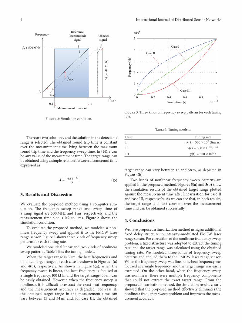
When the target range is 30m the beat frequencies andobtained target range for each case are shown in Figures 4(a)and 4(b) respectively As shown in Figure 4(a) when thefrequency sweep is linear the beat frequency is focused ata single frequency 100 kHz and the target range 30m canbe easily obtained However when the frequency sweep isnonlinear it is difficult to extract the exact beat frequencyand the measurement accuracy is degraded For case IIthe obtained target range in the measurement time canvary between 15 and 34m and for case III the obtained
0 02 04 06 08 10
1
2
3
4
5
Sweep time (s)
Freq
uenc
y (H
z)
Case I
Case II
Case III
times108
times10minus3
Figure 3 Three kinds of frequency sweep patterns for each tuningrate
Table 1 Tuning models
Case Tuning rateI 120574(119905) = 500 times 10
9 (linear)II 120574(119905) = 500 times 10
75119905minus12
III 120574(119905) = 500 times 1012119905
target range can vary between 12 and 58m as depicted inFigure 4(b)
Two kinds of nonlinear frequency sweep patterns areapplied in the proposed method Figures 5(a) and 5(b) showthe simulation results of the obtained target range plottedagainst the measurement time after linearization for case IIand case III respectively As we can see that in both resultsthe target range is almost constant over the measurementtime and can be obtained successfully
4 Conclusions
Wehave proposed a linearizationmethod using an additionalfixed delay structure in intensity-modulated FMCW laserrange sensor For correction of the nonlinear frequency sweepproblem a fixed structure was adopted to extract the tuningrate and the target range was calculated using the obtainedtuning rate We modeled three kinds of frequency sweeppatterns and applied them to the FMCW laser range sensorWhen the frequency sweep was linear the beat frequency wasfocused at a single frequency and the target range was easilyextracted On the other hand when the frequency sweepwas nonlinear there were multiple frequency componentsthat could not extract the exact target range From theproposed linearization method the simulation results clearlyshowed that the proposed method effectively eliminates thenonlinear frequency sweep problem and improves the meas-urement accuracy
International Journal of Distributed Sensor Networks 5
0 1 2 3 4 50
05
1
15
2
Frequency (Hz)
Mag
nitu
de
Case III
Case I (linear)
Case II
times10minus4
times105
(a)
00002 00004 00006 00008 00010
20
30
40
50
60
Case III
Case II
Case I (linear)Rang
e (m
)
Measurement time (s)
(b)
Figure 4 (a) Beat frequencies and (b) obtained target range for the tuning rate models
20
15
25
30
30
30
30
30
30
Before linearization
After linearization
Rang
e (m
)
Rang
e (m
) 2 nm
00002 00004 00006 00008 00010Measurement time (s)00002 00004 00006 00008 00010
Measurement time (s)
(a)
20
30
40
50
60
30
30
30
30
30Before linearization
After linearization
Rang
e (m
)
Rang
e (m
) 2 nm
00002 00004 00006 00008 00010Measurement time (s)
00002 00004 00006 00008 00010Measurement time (s)
(b)
Figure 5 Simulation results after application of the proposed linearization method for the nonlinear frequency sweep of (a) 120574(119905) = 500 times1075119905minus12 and (b) 120574(119905) = 500 times 1012 119905
6 International Journal of Distributed Sensor Networks
Acknowledgments
This work was supported by Priority Research Centers Pro-gram through the National Research Foundation of Korea(NRF) funded by the Ministry of Education Science andTechnology (2009-0093828) and by the National ResearchFoundation of Korea (NRF) Grant funded by the Koreangovernment (MEST) (no 2011-0017081)
References
[1] D C Carmer and L M Peterson ldquoLaser radar in roboticsrdquoProceedings of the IEEE vol 84 no 2 pp 299ndash320 1996
[2] F Blais ldquoReview of 20 years of range sensor developmentrdquoJournal of Electronic Imaging vol 13 no 1 pp 231ndash243 2004
[3] P A Forrester and K F Hulme ldquoLaser rangefindersrdquo Opticaland Quantum Electronics vol 13 no 4 pp 259ndash293 1981
[4] M-C Amann T Bosch M Lescure R Myllyla and M RiouxldquoLaser ranging a critical review of usual techniques for distancemeasurementrdquo Optical Engineering vol 40 no 1 pp 10ndash192001
[5] S M Nejad and S Olyaee ldquoUnified pulsed laser range finderand velocimeter using ultra-Fast time-to-digital converterrdquoIranian Journal of Electrical amp Electronic Engineering vol 5 no2 pp 112ndash121 2009
[6] P Palojarvi K Maatta and J Kostamovaara ldquoPulsed time-of-flight laser radar module with millimeter-level accuracy usingfull custom receiver and TDC ASICsrdquo IEEE Transactions onInstrumentation and Measurement vol 51 no 5 pp 1102ndash11082002
[7] T Bosch andM Lescure ldquoCrosstalk analysis of 1 m to 10m laserphase-shift range finderrdquo IEEE Transactions on Instrumentationand Measurement vol 46 no 6 pp 1224ndash1228 1997
[8] G Perchet and M Lescure ldquoMagnification of phase shift fora laser rangefinder intrinsic resolution and improved circuitrdquoJournal of Optics vol 29 no 3 pp 229ndash235 1998
[9] B L Stann W C Ruff and Z G Sztankay ldquoIntensity-modulated diode laser radar using frequency-modulationcontinuous-wave ranging techniquesrdquo OpticalEngineering vol 35 no 11 pp 3270ndash3278 1996
[10] T-J Ahn J Y Lee and D Y Kim ldquoSuppression of nonlinearfrequency sweep in an optical frequency-domain reflectometerby use of Hilbert transformationrdquoApplied Optics vol 44 no 35pp 7630ndash7634 2005
[11] C J Karlsson and F A A Olsson ldquoLinearization of thefrequency sweep of a frequency-modulated continuous-wavesemiconductor laser radar and the resulting ranging perfor-mancerdquo Applied Optics vol 38 no 15 pp 3376ndash3386 1999
[12] D A Williams ldquoA highly linearized mm-wave voltage con-trolled oscillator for FMCW radar applicationsrdquo IEE Collo-quium on Solid State Components for Radar pp 601ndash615 1988
[13] H-G Park B Kim and Y S Kim ldquoVCO nonlinearity correc-tion scheme for a wideband FM-CW radarrdquo Microwave andOptical Technology Letters vol 25 no 4 pp 266ndash269 2000
[14] T Musch I Rolfes and B Schiek ldquoA highly linear frequencyramp generator based on a fractional divider phase-locked-looprdquo IEEE Transactions on Instrumentation and Measurementvol 48 no 2 pp 634ndash637 1999
[15] M Pichler A Stelzer P Gulden C Seisenberger and MVossiek ldquoFrequency-sweep linearization for FMCW sensors
with high measurement raterdquo in Proceedings of the IEEEMTT-SInternational Microwave Symposium pp 1693ndash1696 June 2005
[16] S Scheiblhofer S Schuster and A Stelzer ldquoSignal modeland linearization for nonlinear chirps in FMCW radar SAW-ID tag requestrdquo IEEE Transactions on Microwave Theory andTechniques vol 54 no 4 pp 1477ndash1483 2006
[17] X N Fernando and A B Sesay ldquoAdaptive asymmetric lin-earization of radio over fiber links for wireless accessrdquo IEEETransactions on Vehicular Technology vol 51 no 6 pp 1576ndash1586 2002
[18] F R Gfeller and U Bapst ldquoWireless in-house data communica-tion via diffuse infrared radiationrdquo Proceedings of the IEEE vol67 no 11 pp 1474ndash1486 1979
International Journal of
AerospaceEngineeringHindawi Publishing Corporationhttpwwwhindawicom Volume 2014
RoboticsJournal of
Hindawi Publishing Corporationhttpwwwhindawicom Volume 2014
Hindawi Publishing Corporationhttpwwwhindawicom Volume 2014
Active and Passive Electronic Components
Control Scienceand Engineering
Journal of
Hindawi Publishing Corporationhttpwwwhindawicom Volume 2014
International Journal of
RotatingMachinery
Hindawi Publishing Corporationhttpwwwhindawicom Volume 2014
Hindawi Publishing Corporation httpwwwhindawicom
Journal ofEngineeringVolume 2014
Submit your manuscripts athttpwwwhindawicom
VLSI Design
Hindawi Publishing Corporationhttpwwwhindawicom Volume 2014
Hindawi Publishing Corporationhttpwwwhindawicom Volume 2014
Shock and Vibration
Hindawi Publishing Corporationhttpwwwhindawicom Volume 2014
Civil EngineeringAdvances in
Acoustics and VibrationAdvances in
Hindawi Publishing Corporationhttpwwwhindawicom Volume 2014
Hindawi Publishing Corporationhttpwwwhindawicom Volume 2014
Electrical and Computer Engineering
Journal of
Advances inOptoElectronics
Hindawi Publishing Corporation httpwwwhindawicom
Volume 2014
The Scientific World JournalHindawi Publishing Corporation httpwwwhindawicom Volume 2014
SensorsJournal of
Hindawi Publishing Corporationhttpwwwhindawicom Volume 2014
Modelling amp Simulation in EngineeringHindawi Publishing Corporation httpwwwhindawicom Volume 2014
Hindawi Publishing Corporationhttpwwwhindawicom Volume 2014
Chemical EngineeringInternational Journal of Antennas and
Propagation
International Journal of
Hindawi Publishing Corporationhttpwwwhindawicom Volume 2014
Hindawi Publishing Corporationhttpwwwhindawicom Volume 2014
Navigation and Observation
International Journal of
Hindawi Publishing Corporationhttpwwwhindawicom Volume 2014
DistributedSensor Networks
International Journal of

2 International Journal of Distributed Sensor Networks
controlled only by an open-loop system inevitable frequencydrifts due to temperature environmental conditions agingand so forth cannot be compensated for The closed-loopcorrectionmethod adopts a phase locked loop (PLL) circuitryto linearize the frequency sweep However because PLLs aredynamic systems any changes in the system input will causethe output not to follow immediately but to exhibit sometransient behavior Such errors in the output frequency willhave a negative influence on the FMCWmeasurement result
To solve these problems we propose a method for cor-rection of frequency-sweep nonlinearity in a signal processorinstead of linearization of the VCO frequency sweep Forlinearization an additional fixed delay structure is adoptedand the frequency-sweep nonlinearity is extracted and usedfor compensationWe validate our linearizationmethod withnumerical analysis and computer simulation
2 Nonlinearity Correction Method
In FMCW technique a transmitter produces an FMCWsignal that is a sinusoidal signal with a constant rate offrequency changeThis signal is backscattered by a target andgoes back to the emitter Beat frequency which is frequencydifference between transmitted signal and backscattered sig-nal contains the distance information
In intensity-modulated FMCW laser range sensor alaser diode (LD) transmits an optical signal with directmodulation and aVCO is adopted for frequencymodulationThe output signal frequency of theVCO is controlled by inputvoltage If the input voltage ofVCO is a ramp signal an opticalsignal with a constant rate of frequency increase is generatedThis optical signal is backscattered by a target and goes backto a photo detector (PD) which can transfer optical signal toelectrical signal Using a mixer and a low pass filter (LPF) asignal with beat frequency is extracted Then the distance ofthe target can be expressed as
119889 =120591RTT sdot 119888
2=119891BEAT sdot 119905RAMP sdot 119888
2 sdot Δ119891 (1)
where 120591RTT is the round trip time of the optical signal 119888 is thespeed of light 119891BEAT is the beat frequency 119905RAMP is period ofthe ramp signal andΔ119891 is frequency sweep range of theVCOIn third term of (1) 119905RAMP 119888 and Δ119891 are known parametersand the beat frequency 119891BEAT is determined by the targetdistance If the frequency sweep is linear the beat frequency isconstant as long as the target range is not changed Howeverin practice an exact ramp-like frequency profile is not easyto obtain If there is nonlinearity in the frequency sweep itmakes problem because the beat frequency is not constantand it is difficult to find exact range
To solve the nonlinear sweep problem we propose equip-ping the FMCW laser range sensor with an additional fixeddelay structure as depicted in Figure 1
As shown in Figure 1 a fixed delay structure is addedfor linearization When a voltage ramp signal is given to theVCO the angular frequency of the VCO output signal can beexpressed as
120596 (119905) = 1205960+ 120574 (119905) sdot 119905 (2)
VCO
Delay
LPF
LPF
Frequencydetector
Frequencydetector
Signal processor
Fixed delay structure
PD
LDRamp generator Targ
et
LD laser diode PD photo detector
VCO voltage controlled oscillatorLPF low pass filter
Figure 1 Block diagram of the proposed FMCW laser range sensor
where 1205960is the initial angular frequency and 120574(119905) means
the tuning rate to be compensated due to nonlinearity Forsimplicity assumingΔ120574(119905) ≪ 119905 the following equation showsthe phase of the VCO output signal
120593 (119905) = int
119905
0
120596 (119905) 119889119905 = 1205930+ 1205960119905 +
1
2120574 (119905) sdot 119905
2 (3)
where 1205930is the initial phaseThen the VCOoutput signal can
be written as
119864VCO (119905) = 119870VCO cos (120593 (119905)) (4)
where 119870VCO is the amplitude of the VCO output signalThis signal is modulated to the laser diode and transmittedto the target Practically the LD output optical power is anonlinear function of the input electrical signal Althoughwe can minimize the nonlinearity by modulating the inputsignal in the linear region of LD the residual components canremain The output from the LD is shown in (5) for a third-order nonlinearity where119898 is the optical modulation indexand119860
2and119860
3are device dependent nonlinearity coefficients
[17]
119875119879(119905) = 119875
0[1 + 119898119870VCO cos (120593 (119905))
+ 119860211989821198702
VCOcos2(120593 (119905))
+ 119860311989831198703
VCOcos3(120593 (119905))]
= 1198750[1 +
1198612
2+ 1198611+31198613
4 cos (120593 (119905))
+1198612cos (2120593 (119905))
2+1198613cos (3120593 (119905))
4]
(5)
where 1198611
= 119898119870VCO 1198612 = 119860211989821198702
VCO and 1198613
=
119860311989831198703
VCO Then the reflected signal detected by PD is
International Journal of Distributed Sensor Networks 3
expressed as [18]
119864PD (119905) = 1198701003816100381610038161003816119877119875119877 (119905)
10038161003816100381610038162
= 119870
1003816100381610038161003816100381610038161003816119877119899 + 1
21205871198892120588119860119877sin2 (FOV) 119875
119879(119905 minus 120591RTT)
1003816100381610038161003816100381610038161003816
2
= 1198620+ 1198621cos (120593 (119905 minus 120591RTT)) + 119862
2cos (2120593 (119905 minus 120591RTT))
+ 1198623cos (3120593 (119905 minus 120591RTT)) + 119862
4cos (4120593 (119905 minus 120591RTT))
+ 1198625cos (5120593 (119905 minus 120591RTT)) + 119862
6cos (6120593 (119905 minus 120591RTT))
(6)
where 119875119877(119905) is the received optical signal 119877 is responsivity of
the PD119870 is constant of proportionality 119899 is a mode number119889 is the target range 120588 is a reflection coefficient 119860
119877is the
photosensitive area of the PD FOV is a field of view and120591RTT is the round trip time of the transmitted signalTheVCOoutput signal and the reflected signal are multiplied througha mixer and a signal with the beat frequency is obtained afterLPF expressed as
119864BEAT (119905) =119870VCO1198621
2cos (120593 (119905) minus 120593 (119905 minus 120591RTT)) (7)
A frequency detector is used for detecting the frequencyof the signal after LPF A reciprocal frequency counter canbe used as the frequency detector Because the reciprocalfrequency counter measures the period for one cycle ofthe waveform it can support high resolution and very fastreadings Also a Schmitt trigger circuit can be used at inputstage of the frequency detector so that noise does not causespurious edges Because frequency is derivative of phase theangular frequency to be detected is expressed as
120596BEAT (119905) =119889
119889119905[120593 (119905) minus 120593 (119905 minus 120591RTT)]
= 120591RTT sdot 120574 (119905) + 120591RTT119889120574 (119905)
119889119905119905 minus
120591RTT2
2
119889120574 (119905)
119889119905
(8)
As we can see in (8) if the tuning rate 120574(119905) is constantthen the angular frequency difference 120596BEAT(119905) is equal tothe product of the round trip time and the tuning rateBecause 120596BEAT(119905) can be detected by the frequency detectorand the tuning rate is a known value it is easy to find theround trip time and we can extract the range of thetargetHowever usually the frequency sweep of a VCO is notperfectly linear that is the tuning rate is not constant Thenthe beat frequency cannot give the exact round trip time
To solve this problem we added a fixed delay structurefor obtaining the tuning rate The frequency detector can
detect the frequency difference between the VCO output anddelayed output signal expressed as
120596AUX (119905) =119889
119889119905[120593 (119905) minus 120593 (119905 minus 120591
119863)]
= 120591119863sdot 120574 (119905) + 120591
119863
119889120574 (119905)
119889119905119905 minus
1205912
119863
2
119889120574 (119905)
119889119905
(9)
where 120591119863is the time delay in the fixed delay structure and
is much smaller than the frequency sweep time of the rampsignal In (9)120596AUX(119905) can be detected by a frequency detectorwith the time delay Thus using the ordinary differentialequation the tuning rate 120574(119905) can be calculated as
120574 (119905) = exp(minusint 2
2119905 minus 120591119863
119889119905)
sdot [int2
2119905 minus 120591119863
120596AUX (119905)
120591119863
exp(int 2
2119905 minus 120591119863
119889119905) 119889119905]
= exp (minus ln 10038161003816100381610038162119905 minus 120591119863
1003816100381610038161003816)
sdot [int2
2119905 minus 120591119863
120596AUX (119905)
120591119863
exp (ln 10038161003816100381610038162119905 minus 120591119863
1003816100381610038161003816) 119889119905]
=1
10038161003816100381610038162119905 minus 120591119863
1003816100381610038161003816
sdot [2
120591119863
int
10038161003816100381610038162119905 minus 120591119863
1003816100381610038161003816
2119905 minus 120591119863
120596AUX (119905) 119889119905]
(10)
Because the time delay is much smaller than frequencysweep time of the ramp signal as mentioned above 119905 is largerthan 120591
1198632 in (10) Accordingly the tuning rate can be
120574 (119905) =1
2119905 minus 120591119863
sdot [2
120591119863
int
119905
1205911198632
120596AUX (119905) 119889119905] (11)
The derivative of the tuning rate can be obtained from (9)and expressed as
119889120574 (119905)
119889119905=
2
2119905 minus 120591119863
(120596AUX (119905)
120591119863
minus 120574 (119905)) (12)
Using (8) and (12) we can obtain a quadratic equation for120591RTT which is expressed as
1
2
2
2119905 minus 120591119863
(120596AUX (119905)
120591119863
minus 120574 (119905)) 1205912
RTT
minus 120574 (119905) +2119905
2119905 minus 120591119863
(120596AUX (119905)
120591119863
minus 120574 (119905)) 120591RTT
+ 120596BEAT (119905) = 0
(13)
The solutions of (13) are expressed as
120591RTT =(2119905 (2119905 minus 120591
119863)) (120596AUX (119905) 120591119863 minus 120591
119863120574 (119905) 2119905)
(2 (2119905 minus 120591119863)) (120596AUX (119905) 120591119863 minus 120574 (119905))
plusmn
radic(2119905 (2119905 minus 120591119863)) (120596AUX (119905) 120591119863 minus 120591
119863120574 (119905) 2119905)
2minus ((4 sdot 120596BEAT (119905)) (2119905 minus 120591
119863)) (120596AUX (119905) 120591119863 minus 120574 (119905))
(2 (2119905 minus 120591119863)) (120596AUX (119905) 120591119863 minus 120574 (119905))
(14)
4 International Journal of Distributed Sensor Networks
Frequency
Measurement time slot
Reference (transmitted)
signalReflected
signal
Δf(=500
MH
z)
f0120591RTT
fBEAT
t (ms)02 1
f0 + 500MHz
Figure 2 Simulation condition
There are two solutions and the solution in the detectablerange is selected The obtained round trip time is constantover the measurement time lying between the maximumround trip time and the frequency sweep time In (14) 119905 canbe any value of the measurement time The target range canbe obtained using a simple relation between distance and timeexpressed as
119889 =120591RTT sdot 119888
2 (15)
3 Results and Discussion
We evaluate the proposed method using a computer sim-ulation The frequency sweep range and sweep time ofa ramp signal are 500MHz and 1ms respectively and themeasurement time slot is 02 to 1ms Figure 2 shows thesimulation condition
To evaluate the proposed method we modeled a non-linear frequency sweep and applied it to the FMCW laserrange sensor Figure 3 shows three kinds of frequency sweeppatterns for each tuning rate
We modeled one ideal linear and two kinds of nonlinearsweep patterns Table 1 lists the tuning models
When the target range is 30m the beat frequencies andobtained target range for each case are shown in Figures 4(a)and 4(b) respectively As shown in Figure 4(a) when thefrequency sweep is linear the beat frequency is focused ata single frequency 100 kHz and the target range 30m canbe easily obtained However when the frequency sweep isnonlinear it is difficult to extract the exact beat frequencyand the measurement accuracy is degraded For case IIthe obtained target range in the measurement time canvary between 15 and 34m and for case III the obtained
0 02 04 06 08 10
1
2
3
4
5
Sweep time (s)
Freq
uenc
y (H
z)
Case I
Case II
Case III
times108
times10minus3
Figure 3 Three kinds of frequency sweep patterns for each tuningrate
Table 1 Tuning models
Case Tuning rateI 120574(119905) = 500 times 10
9 (linear)II 120574(119905) = 500 times 10
75119905minus12
III 120574(119905) = 500 times 1012119905
target range can vary between 12 and 58m as depicted inFigure 4(b)
Two kinds of nonlinear frequency sweep patterns areapplied in the proposed method Figures 5(a) and 5(b) showthe simulation results of the obtained target range plottedagainst the measurement time after linearization for case IIand case III respectively As we can see that in both resultsthe target range is almost constant over the measurementtime and can be obtained successfully
4 Conclusions
Wehave proposed a linearizationmethod using an additionalfixed delay structure in intensity-modulated FMCW laserrange sensor For correction of the nonlinear frequency sweepproblem a fixed structure was adopted to extract the tuningrate and the target range was calculated using the obtainedtuning rate We modeled three kinds of frequency sweeppatterns and applied them to the FMCW laser range sensorWhen the frequency sweep was linear the beat frequency wasfocused at a single frequency and the target range was easilyextracted On the other hand when the frequency sweepwas nonlinear there were multiple frequency componentsthat could not extract the exact target range From theproposed linearization method the simulation results clearlyshowed that the proposed method effectively eliminates thenonlinear frequency sweep problem and improves the meas-urement accuracy
International Journal of Distributed Sensor Networks 5
0 1 2 3 4 50
05
1
15
2
Frequency (Hz)
Mag
nitu
de
Case III
Case I (linear)
Case II
times10minus4
times105
(a)
00002 00004 00006 00008 00010
20
30
40
50
60
Case III
Case II
Case I (linear)Rang
e (m
)
Measurement time (s)
(b)
Figure 4 (a) Beat frequencies and (b) obtained target range for the tuning rate models
20
15
25
30
30
30
30
30
30
Before linearization
After linearization
Rang
e (m
)
Rang
e (m
) 2 nm
00002 00004 00006 00008 00010Measurement time (s)00002 00004 00006 00008 00010
Measurement time (s)
(a)
20
30
40
50
60
30
30
30
30
30Before linearization
After linearization
Rang
e (m
)
Rang
e (m
) 2 nm
00002 00004 00006 00008 00010Measurement time (s)
00002 00004 00006 00008 00010Measurement time (s)
(b)
Figure 5 Simulation results after application of the proposed linearization method for the nonlinear frequency sweep of (a) 120574(119905) = 500 times1075119905minus12 and (b) 120574(119905) = 500 times 1012 119905
6 International Journal of Distributed Sensor Networks
Acknowledgments
This work was supported by Priority Research Centers Pro-gram through the National Research Foundation of Korea(NRF) funded by the Ministry of Education Science andTechnology (2009-0093828) and by the National ResearchFoundation of Korea (NRF) Grant funded by the Koreangovernment (MEST) (no 2011-0017081)
References
[1] D C Carmer and L M Peterson ldquoLaser radar in roboticsrdquoProceedings of the IEEE vol 84 no 2 pp 299ndash320 1996
[2] F Blais ldquoReview of 20 years of range sensor developmentrdquoJournal of Electronic Imaging vol 13 no 1 pp 231ndash243 2004
[3] P A Forrester and K F Hulme ldquoLaser rangefindersrdquo Opticaland Quantum Electronics vol 13 no 4 pp 259ndash293 1981
[4] M-C Amann T Bosch M Lescure R Myllyla and M RiouxldquoLaser ranging a critical review of usual techniques for distancemeasurementrdquo Optical Engineering vol 40 no 1 pp 10ndash192001
[5] S M Nejad and S Olyaee ldquoUnified pulsed laser range finderand velocimeter using ultra-Fast time-to-digital converterrdquoIranian Journal of Electrical amp Electronic Engineering vol 5 no2 pp 112ndash121 2009
[6] P Palojarvi K Maatta and J Kostamovaara ldquoPulsed time-of-flight laser radar module with millimeter-level accuracy usingfull custom receiver and TDC ASICsrdquo IEEE Transactions onInstrumentation and Measurement vol 51 no 5 pp 1102ndash11082002
[7] T Bosch andM Lescure ldquoCrosstalk analysis of 1 m to 10m laserphase-shift range finderrdquo IEEE Transactions on Instrumentationand Measurement vol 46 no 6 pp 1224ndash1228 1997
[8] G Perchet and M Lescure ldquoMagnification of phase shift fora laser rangefinder intrinsic resolution and improved circuitrdquoJournal of Optics vol 29 no 3 pp 229ndash235 1998
[9] B L Stann W C Ruff and Z G Sztankay ldquoIntensity-modulated diode laser radar using frequency-modulationcontinuous-wave ranging techniquesrdquo OpticalEngineering vol 35 no 11 pp 3270ndash3278 1996
[10] T-J Ahn J Y Lee and D Y Kim ldquoSuppression of nonlinearfrequency sweep in an optical frequency-domain reflectometerby use of Hilbert transformationrdquoApplied Optics vol 44 no 35pp 7630ndash7634 2005
[11] C J Karlsson and F A A Olsson ldquoLinearization of thefrequency sweep of a frequency-modulated continuous-wavesemiconductor laser radar and the resulting ranging perfor-mancerdquo Applied Optics vol 38 no 15 pp 3376ndash3386 1999
[12] D A Williams ldquoA highly linearized mm-wave voltage con-trolled oscillator for FMCW radar applicationsrdquo IEE Collo-quium on Solid State Components for Radar pp 601ndash615 1988
[13] H-G Park B Kim and Y S Kim ldquoVCO nonlinearity correc-tion scheme for a wideband FM-CW radarrdquo Microwave andOptical Technology Letters vol 25 no 4 pp 266ndash269 2000
[14] T Musch I Rolfes and B Schiek ldquoA highly linear frequencyramp generator based on a fractional divider phase-locked-looprdquo IEEE Transactions on Instrumentation and Measurementvol 48 no 2 pp 634ndash637 1999
[15] M Pichler A Stelzer P Gulden C Seisenberger and MVossiek ldquoFrequency-sweep linearization for FMCW sensors
with high measurement raterdquo in Proceedings of the IEEEMTT-SInternational Microwave Symposium pp 1693ndash1696 June 2005
[16] S Scheiblhofer S Schuster and A Stelzer ldquoSignal modeland linearization for nonlinear chirps in FMCW radar SAW-ID tag requestrdquo IEEE Transactions on Microwave Theory andTechniques vol 54 no 4 pp 1477ndash1483 2006
[17] X N Fernando and A B Sesay ldquoAdaptive asymmetric lin-earization of radio over fiber links for wireless accessrdquo IEEETransactions on Vehicular Technology vol 51 no 6 pp 1576ndash1586 2002
[18] F R Gfeller and U Bapst ldquoWireless in-house data communica-tion via diffuse infrared radiationrdquo Proceedings of the IEEE vol67 no 11 pp 1474ndash1486 1979
International Journal of
AerospaceEngineeringHindawi Publishing Corporationhttpwwwhindawicom Volume 2014
RoboticsJournal of
Hindawi Publishing Corporationhttpwwwhindawicom Volume 2014
Hindawi Publishing Corporationhttpwwwhindawicom Volume 2014
Active and Passive Electronic Components
Control Scienceand Engineering
Journal of
Hindawi Publishing Corporationhttpwwwhindawicom Volume 2014
International Journal of
RotatingMachinery
Hindawi Publishing Corporationhttpwwwhindawicom Volume 2014
Hindawi Publishing Corporation httpwwwhindawicom
Journal ofEngineeringVolume 2014
Submit your manuscripts athttpwwwhindawicom
VLSI Design
Hindawi Publishing Corporationhttpwwwhindawicom Volume 2014
Hindawi Publishing Corporationhttpwwwhindawicom Volume 2014
Shock and Vibration
Hindawi Publishing Corporationhttpwwwhindawicom Volume 2014
Civil EngineeringAdvances in
Acoustics and VibrationAdvances in
Hindawi Publishing Corporationhttpwwwhindawicom Volume 2014
Hindawi Publishing Corporationhttpwwwhindawicom Volume 2014
Electrical and Computer Engineering
Journal of
Advances inOptoElectronics
Hindawi Publishing Corporation httpwwwhindawicom
Volume 2014
The Scientific World JournalHindawi Publishing Corporation httpwwwhindawicom Volume 2014
SensorsJournal of
Hindawi Publishing Corporationhttpwwwhindawicom Volume 2014
Modelling amp Simulation in EngineeringHindawi Publishing Corporation httpwwwhindawicom Volume 2014
Hindawi Publishing Corporationhttpwwwhindawicom Volume 2014
Chemical EngineeringInternational Journal of Antennas and
Propagation
International Journal of
Hindawi Publishing Corporationhttpwwwhindawicom Volume 2014
Hindawi Publishing Corporationhttpwwwhindawicom Volume 2014
Navigation and Observation
International Journal of
Hindawi Publishing Corporationhttpwwwhindawicom Volume 2014
DistributedSensor Networks
International Journal of

International Journal of
AerospaceEngineeringHindawi Publishing Corporationhttpwwwhindawicom Volume 2014
RoboticsJournal of
Hindawi Publishing Corporationhttpwwwhindawicom Volume 2014
Hindawi Publishing Corporationhttpwwwhindawicom Volume 2014
Active and Passive Electronic Components
Control Scienceand Engineering
Journal of
Hindawi Publishing Corporationhttpwwwhindawicom Volume 2014
International Journal of
RotatingMachinery
Hindawi Publishing Corporationhttpwwwhindawicom Volume 2014
Hindawi Publishing Corporation httpwwwhindawicom
Journal ofEngineeringVolume 2014
Submit your manuscripts athttpwwwhindawicom
VLSI Design
Hindawi Publishing Corporationhttpwwwhindawicom Volume 2014
Hindawi Publishing Corporationhttpwwwhindawicom Volume 2014
Shock and Vibration
Hindawi Publishing Corporationhttpwwwhindawicom Volume 2014
Civil EngineeringAdvances in
Acoustics and VibrationAdvances in
Hindawi Publishing Corporationhttpwwwhindawicom Volume 2014
Hindawi Publishing Corporationhttpwwwhindawicom Volume 2014
Electrical and Computer Engineering
Journal of
Advances inOptoElectronics
Hindawi Publishing Corporation httpwwwhindawicom
Volume 2014
The Scientific World JournalHindawi Publishing Corporation httpwwwhindawicom Volume 2014
SensorsJournal of
Hindawi Publishing Corporationhttpwwwhindawicom Volume 2014
Modelling amp Simulation in EngineeringHindawi Publishing Corporation httpwwwhindawicom Volume 2014
Hindawi Publishing Corporationhttpwwwhindawicom Volume 2014
Chemical EngineeringInternational Journal of Antennas and
Propagation
International Journal of
Hindawi Publishing Corporationhttpwwwhindawicom Volume 2014
Hindawi Publishing Corporationhttpwwwhindawicom Volume 2014
Navigation and Observation
International Journal of
Hindawi Publishing Corporationhttpwwwhindawicom Volume 2014
DistributedSensor Networks
International Journal of