Embed Size (px)
Citation preview

www.vishay.com
22
Document Number: 81463
Rev. 1.0, 12-Sep-06
Quality and ReliabilityVishay Semiconductors
Quality Information
Figure 1. Vishay quality policy
Our goal is to exceed the quality
expectations of our customers.
This commitment starts with top
management and extends through
the entire organization. It is achieved
through innovation, technical excellence
and continuous improvement.
Corporate Quality Policy
18348

Quality and Reliability
Document Number: 81463
Rev. 1.0, 12-Sep-06
Vishay Semiconductors
www.vishay.com
23
VISHAY INTERTECHNOLOGY; INC.
ENVIRONMENTAL, HEALTH AND SAFETY POLICY
VISHAY INTERTECHNOLOGY, INC. is committed to conducting its worldwide operations in asocially responsible and ethical manner to protect the environment, and ensure the safety and healthof our employees to conduct their daily activities in an environmentally responsible manner.
Protection of the Environment: Conduct our business operation in a manner that protects the envi-ronmental quality of the communities in which our facilities are located. Reduce risks involved withstorage and use of hazardous materials. The company is also committed to continual improvementof its environmental performance.
Compliance with Environmental, Health and Safety Laws and Regulations:Comply with all relevant environmental, health and safety laws and regulations in every location.Maintain a system that provides timely updates of regulatory change.Cooperate fully with governmental agencies in meeting applicable requirements.
Energy, Resource Conservation and Pollution Control: Strive to minimize energy and materialconsumption in the design of products and processes, and in the operation of our facilities. Promotethe recycling of materials, including hazardous wastes, whenever possible. Minimize the generationof hazardous and non-hazardous wastes at our facilities to prevent or eliminate pollution. Manageand dispose of wastes safely and responsibly.

www.vishay.com
24
Document Number: 81463
Rev. 1.0, 12-Sep-06
Quality and ReliabilityVishay Semiconductors
Quality System
Quality ProgramAt the heart of the quality process is the Vishay world-wide quality program. This program, which has beenin place since the early 90's, is specifically designedto meet rapidly increasing customer quality demandsnow and in the future.Vishay Corporate Quality implements the Quality Pol-icy and translates its requirements for use throughoutthe worldwide organization.Vishay Quality has defined a roadmap with specifictargets along the way. The major target is to achieveworld-class excellence throughout Vishay worldwideby 2008.
VISHAY Corporate QualityThe Vishay Corporate Quality defines and imple-ments the Vishay quality policy at a corporate level. Itacts to harmonize the quality systems of the constitu-ent divisions and to implement Total Quality Manage-ment throughout the company worldwide.
Vishay Zero Defect Program• Exceeding quality expectations of our customers• Commitment from top management through entire organization• Newest and most effective procedures and tools - design, manufacturing and testing - management procedures (eg. SPC, TQM)• Continuous decreasing numbers for AOQ and Failure Rate• Detailed failure analysis using 8D methodology• Continuous improvement of quality performance of parts and technology
Figure 2. Vishay Quality road map
19593
lC dlroW lecxE ssa ecnellC dlroW lecxE ssa ecnel
8002
0991
5991
0002ssenisuB detneirO ssecorP 0002:1009 OSI
10041 OSI
DV / 0009 SQ 1.6 A
hcaorppA MQFE
M e merusa e motsuC tn itcafsitaS re no
yciloP ecivreS remotsuC etaroproC
0009 OSI
pihsrentraP reilppuS
ilauQ fo tsoC ty
Q decnavdA u slooT ytila
smaeT tnemevorpmI derewopmE
smetsyS tnemeganaM detargetnI
,SHoR ,VLE evitceriD-CE dellifluf EEEW
- 94961 ST/OSI A motu dradnatS evito

Quality and Reliability
Document Number: 81463
Rev. 1.0, 12-Sep-06
Vishay Semiconductors
www.vishay.com
25
Quality Goals and MethodsThe goals are straightforward: Customer satisfactionthrough continuous improvement towards zerodefects in every area of our operation. We are com-mitted to meet our customers' requirements in termsof quality and service. In order to achieve this, webuild excellence into our product from concept todelivery and beyond. • Design-in QualityQuality must be designed into products. Vishay usesoptimized design rules based on statistical informa-tion. This is refined using electrical, thermal andmechanical simulation together with techniques suchas FMEA, QFD and DOE. • Built-in QualityQuality is built into all Vishay products by using quali-fied materials, suppliers and processes. Fundamentalto this is the use of SPC techniques by both Vishayand its suppliers. The use of these techniques, as wellas tracking critical processes, reduces variability,optimizing the process with respect to the specifica-tion. The target is defect prevention and continuousimprovement. • QualificationAll new products are qualified before release by sub-mitting them to a series of mechanical, electrical andenvironmental tests. The same procedure is used fornew or changed processes or packages. • MonitoringA selection of the same or similar tests used for qual-ification is also used to monitor the short- and long-term reliability of the product. • SPC (Statistical Process Control)SPC is an essential part of all Vishay process control.It has been established for many years and is used asa tool for the continuous improvement of processesby measuring, controlling and reducing variability. • Vishay Quality SystemAll Vishay's facilities worldwide are approved to ISO 9000. In addition, depending on their activities,some Vishay companies are approved to recognizedinternational and industry standards such as VDA 6.1and QS 9000. Each subsidiary goal is to fulfill the par-ticular requirements of customers. The Opto Divisionsof Vishay Semiconductor GmbH are certified accord-ing to ISO 9001:2000, QS 9000 and ISO/TS 16949.
The procedures used are based upon these stan-dards and laid down in an approved and controlledQuality Manual.
Total Quality ManagementTotal Quality Management is a management systemcombining the resources of all employees, customersand suppliers in order to achieve total customer satis-faction. The fundamental elements of this system are: • Management commitment • European Foundation for Quality Management
(EFQM assessment methodology) • Empowered Improvement Teams (EITs) • Supplier development and partnership • Quality tools • Training • Quality SystemAll Vishay employees from the senior managementdownwards are trained in understanding and using ofTQM. Every employee plays its own part in the con-tinuous improvement process which is fundamental toTQM and our corporate commitment to exceed cus-tomers' expectations in all areas including design,technology, manufacturing, human resources, mar-keting, and finance. Everyone is involved in fulfillingthis goal. The management believes that this can onlybe achieved by employee empowerment.The Vishay corporate core values • Leadership by example • Employee empowerment • Continuous improvement • Total customer satisfaction • Business excellenceare the very essence of the Vishay Quality Movementprocess.
SLAOG SLAOG
morf sevitceriD morf sevitceriD ::
S etroppu d yb S etroppu d yb ::
InputsInputs fromfrom::
Div
isio
n
yeK yeK rP oc sesserP oc sesse ::
tnempoleveD o weN f P stcudor
remotsuC ytilauQ
noitcasnarT sredrO fo
araP yeK me retTR ,MV M
rP maS tcudo p selgM tcejorP mt
dleiY
suC,MV remot A .ccyC elc T mi eaS les/ASP
ruT ns
Re nops T es imeteR urnsOA Q
aR w M ate lair
esaB ataDstcudorP weN
sraey3>
nI otnev rriesrP sessimo
ruT ns
OA Q, eR ut nr sialpmoC n st
C-Q osts
ProcessProcess OutputsOutputs
Co suounitn vorpmI ementCo suounitn vorpmI ementACDP( ACDP( -- cyC lecyC le))
nalP in ng
aM kr gnite
nisahcruP g
nE ,D&R ig gnireen
noitcudorP
ytilauQ
orivnE tnemn
Inter-
acountability
Strategy
-C
uC
lture
QM
Con
trolli
ng
Sal
es
FSG
,HR
,AC
C.
aM
rcom
,LO
G,IT
Pro
ject
-a
Mna
gee
mnt
yeK yeK snoitcnuf snoitcnuf ::eroF ac ts
drO er
cudorP st
uC ts mo reR stseuqe
CustomerQualitiy
tO hergA eer m stne
sdradnatSwaL s
19594

www.vishay.com
26
Document Number: 81463
Rev. 1.0, 12-Sep-06
Quality and ReliabilityVishay Semiconductors
• TrainingVishay maintains that it can only realize its aims if theemployees are well trained. It therefore investsheavily in courses to provide all employees with theknowledge they need to facilitate continuous improve-ment. A training profile has been established for allemployees with emphasis being placed on TotalQuality Leadership. Our long-term aim is to continu-ously improve our training so as to keep ahead of pro-jected changes in business and technology. • EFQM Assessment MethodologyFrom 1995, Vishay has started to introduce theEFQM (European Foundation for Quality Manage-ment) methodology for structuring its Total QualityManagement approach. This methodology, similar tothe Malcolm Baldrige process, consists in self-assessing the various Vishay divisions and facilitiesaccording to nine business criteria: • Leadership • People • Policy & Strategy • Partnership & Resources • Processes • People Results • Customer Results • Society Results • Key Performance Results(see figure 3)
The assessments are conducted on a yearly basis bytrained and empowered, internal Vishay assessors.This permits the identification of keypriority improve-ment projects and the measurement of the progressaccomplished. The EFQM methodology helps Vishay to achieveworld-class business excellence. • Empowered Improvement Teams (EITs)At Vishay we believe that every person in the com-pany has a contribution to make in meeting our targetof customer satisfaction. Management thereforeempowers employees to higher and higher levels ofmotivation, thus achieving higher levels of effective-ness and productivity. Empowered improvementteams, which are both functional and cross functional,combine the varied talents from across the breadth ofthe company. By taking part in training, these teamsare continually searching for ways to improve theirjobs, achieving satisfaction for themselves, the com-pany and most important of all the customer.
lpoeP elpoeP e
citiloP y andygetartS
citiloP y andygetartS
ihsrentraP p a s dncruoseR es
ihsrentraP p a s dncruoseR es
Pro
cess
esP
roce
sses
ler remotsuC a detstluseR
ler remotsuC a detstluseR
lpoeP etaler e dstluseR
lpoeP etaler e dstluseR
teicoS y r e detalstluseR
oS ic ety er la detstluseR
GNINRAEL & NOITAVONNI
SRELBANE STLUSER
Lead
ersh
ipLe
ader
ship
Key
Per
form
ance
Res
ults
Key
Per
form
ance
Res
ults
19595
Figure 3. EFQM criteria for self-assessment

Quality and Reliability
Document Number: 81463
Rev. 1.0, 12-Sep-06
Vishay Semiconductors
www.vishay.com
27
TQM ToolsAs part of its search for excellence, Vishay employsmany different techniques and tools. The most impor-tant of them are: • AuditingAs well as third party auditing employed for approvalby ISO 9000 and customers, Vishay carries out itsown internal and external auditing. There is a com-mon auditing procedure for suppliers and sub-con-tractors between the Vishay entities. This procedureis also used for inter-company auditing between thefacilities within Vishay. It is based on the "ContinuousImprovement" concept with heavy emphasis on theuse of SPC and other statistical tools for the controland reduction of variability.Internal audits are carried out on a routine basis. Theyinclude audits of satellite facilities (i.e., sales offices,warehousing etc.). Audits are also used widely todetermine attitudes and expectations both within andoutside the company.
• Failure Mode and Effect Analysis (FMEA)FMEA is a technique for analyzing the possible meth-ods of failure and their effect upon the performance/reliability of the product/process. Process FMEAs areperformed for all processes. In addition, productFMEAs are performed on all critical or customer prod-ucts. • Design of Experiments (DOE)There is a series of tools that may be used for the sta-tistical design of experiments. It consists of a formal-ized procedure for optimizing and analyzingexperiments in a controlled manner. Taguchi and fac-torial experiment design are included in this. Theyprovide a major advantage in determining the mostimportant input parameters, making the experiment
more efficient and promoting common understandingamong team members of the methods and principlesused. • Gauge Repeatability and Reproducibility
(GR&R)This technique is used to determine equipment’s suit-ability for purpose. It is used to make certain that allequipment is capable of functioning to the requiredaccuracy and repeatability. All new equipment isapproved before use by this technique. • Quality Function Deployment (QFD)QFD is a method for translating customer require-ments into recognizable requirements for Vishay’smarketing, design, research, manufacturing andsales (including after-sales). QFD is a process, whichbrings together the life cycle of a product from its con-ception, through design, manufacture, distributionand use until it has served its expected life.
Quality ServiceVishay believes that quality of service is equally asimportant as the technical ability of its products tomeet their required performance and reliability. • Our objectives therefore include: • On-time delivery • Short response time to customers’ requests • Rapid and informed technical support • Fast handling of complaints • A partnership with our customers
• Customer ComplaintsComplaints fall mainly into two categories: • Logistical • Technical
18351
18352

www.vishay.com
28
Document Number: 81463
Rev. 1.0, 12-Sep-06
Quality and ReliabilityVishay Semiconductors
Vishay has a procedure detailing the handling of com-plaints. Initially complaints are forwarded to theappropriate sales office where in-depth informationdescribing the problem, using the Vishay ProductAnalysis Request and Return Form (PARRF), is ofconsiderable help in giving a fast and accurateresponse. If it is necessary to send back the productfor logistical reasons, the Sales Office issues aReturned Material Authorization (RMA) number. Onreceipt of the goods in good condition, credit is auto-matically issued. If there is a technical reason forcomplaint, sample together with the PARRF is sent tothe Sales Office for forwarding to the Failure AnalysisDepartment of the supplying facility. The device’sreceipt will be acknowledged and a report issued oncompletion of the analysis. The cycle time this analy-sis has set targets and is constantly monitored inorder to improve the response time. Failure analysisnormally consists of electrical testing, functional test-ing, mechanical analysis (including X-ray), decapsu-lation, visual analysis and electrical probing. Other
specialized techniques (i.e. LCD, thermal imaging,SEM, acoustic microscopy) may be used if neces-sary. If the analysis uncovers a quality problem, CorrectiveAction Report (CAR) in 8D format will be issued. Anysubsequent returns are handled with the RMA proce-dure.
Complaint and Return Procedure
18353
Yes
No
Customer notifies Vishay SalesOffice of a complaint and Sales obtainsthe necessary information about returnusing attached form (Product AnalysisRequest and Return Form)
Customer has a complaintregarding Commercial Aspectse.g. Incorrect products, stockrotation, wrong delivery times orquantities
Customer has a complaintregarding Technical Aspects e.g.Product out of specification,labeling error, and packagingissues
Customer sends samples todesignated factory location(communicated by Sales)
Customer receives an analysisreport from Vishay with referencenumber
End of return procedure
Entitled toreturn/replacementproducts
Sales assign RMA numberand Customer returnsproduct
18354

Quality and Reliability
Document Number: 81463
Rev. 1.0, 12-Sep-06
Vishay Semiconductors
www.vishay.com
29
Product Analysis Request and Return Form (PARRF)
P roduct A nalysis R equest and R eturn F orm
QM Vishay Issue: 02.10.2000
Address Data Customer: Sales Ref.No:
Address: Sales Office: Incoming Date:
Customer Ref.-No: Cust. Contact
Person: Sales Contact
Person: E-Mail: E-Mail: Phone: Phone:
Fax: Fax:
P roduct Analysis Request
Device: Qty. for Analysis: Date Code: Plant Code: Failure Rate:
Type of Complaint (pls. specify) Failure description Electr. Mechan. Others
Point of Failure: Incoming Qualification Assembly Reliability
Field Failure Others
Stress Conditions before Failure: (Temp / %HR / Voltage / Others) Application: (please specify) Remarks / Other Data: (please specify)
R eturn RequestDevice:
Date Code: Inv. No.:
Commercial Return
Technical Return
CAR-No. of 8D - Report:
RMA-No. : ( mandatory )
19596

www.vishay.com
30
Document Number: 81463
Rev. 1.0, 12-Sep-06
Quality and ReliabilityVishay Semiconductors
Vishay 8D form
MANUFACTURER OF ONE OF THE WORLD’S BROADEST L INE OF DISCRETE SEMICONDUCTORS AND PASSIVE COMPONENTS
Confidential Information
8D APPROACH – Disciplines 1, 2, and 4 below must be completed for ALL requests.
DISCIPLINE 1: ESTABLISH TEAMS
DISCIPLINE 2: DESCRIBE PROBLEM
DISCIPLINE 3: CONTAINMENT ACTIONS
DISCIPLINE 4: ROOT CAUSE/RESULTS
If VALID, ALL Disciplines must be completed. DISCIPLINE 5: CORRECTIVE ACTIONS
DISCIPLINE 6: IMPLEMENT CORRECTIVE ACTIONS
DISC IPLINE 7: PREVENT RECURRENCE
DISCIPLINE 8: CONGRATULATE TEAM
Revised by: Rev.: Date: Approved by: Date: Date Closed:
Form # CQA004 Rev B 04/26/02
Company Address
Company Phone Number
CAR Number:
Page: 1
Report Date: VISHAY Company Name 8D Report
Complete following for all applicable items:
Date Opened: Originator Company Specific Information
Vishay Location: Vishay Part No.: Plant code:
Customer: Date Code: Lot Serial No.:
Customer Location: Device Type: Lot size:
Customer Ref. Co de: Value: Sample Qty:
Customer Part No.: Tolerance: Failure rate:
Customer P.O. No.: RMA Number:
Analysis Code: Package Type:
19598

Quality and Reliability
Document Number: 81463
Rev. 1.0, 12-Sep-06
Vishay Semiconductors
www.vishay.com
31
• Change NotificationAll product and process changes are controlled andreleased via ECN (Engineering Change Notification).This requires the approval of the relevant depart-ments. In the case of a major change, the change isforwarded to customers via Sales/ Marketing beforeimplementation. Where specific agreements are inplace, the change will not be implemented unlessapproved by the customer.
• Ship-to-Stock/Ship-to-Line (STS/STL)Many customers now require devices to be shippeddirect to stock or to the production line by omitting anygoods inwards inspection. Vishay welcomes suchagreements as part of its customer partnership pro-gram, which promises an open approach in everyaspect of its business. A product will only be suppliedas STS or STL if there is a valid agreement in placebetween the two companies. Such an agreementdetails the quality level targets agreed upon betweenthe companies and the methods to be used in case ofproblems.
Quality and Reliability
Assurance ProgramThough both quality and reliability are designed intoall Vishay products, three basic programs mustassure them: • Average Outgoing Quality (AOQ) –
100 % testing is followed by sample testing tomeasure the defect level of the shipped product.This defect level (AOQ) is measured in ppm (partsper million).
• Reliability qualification program – to assure that the design, process or change isreliable.
• Reliability monitoring program – to measure and assure that there is no decreasein the reliability of the product.
AOQ ProgramBefore leaving the factory, all products are sampledafter 100% testing to ensure that they meet a mini-mum quality level and to measure the level of defects.The results are accumulated and expressed in ppm(parts per million). They are the measure of the aver-age number of potentially failed parts in deliveriesover a period of time. The sample size used is deter-mined by AQL or LTPD tables depending upon theproduct. No rejects are allowed in the sample.The AOQ value is calculated monthly using themethod defined in standard JEDEC 16:
where:
LAR = lot acceptance rate:
The AOQ values are recorded separately with regardto electrical and mechanical (visual) rejects by prod-uct type and package.The actual qualification procedure depends on whichof these (or combinations of these) are to be qualified.Normally there are three categories of qualification inorder of degree of qualification and testing required: • New technology or process (this includes a new
design on a new process)
18357
AOQ p LAR 106
ppm( )⋅ ⋅=
p number of devices rejectedtotal number of devices tested--------------------------------------------------------------------------------=
LAR 1 number of lots rejectedtotal number of lots tested---------------------------------------------------------------------–=

www.vishay.com
32
Document Number: 81463
Rev. 1.0, 12-Sep-06
Quality and ReliabilityVishay Semiconductors
• New product or re-designed product using a qual-ified processNew package including piece-part or materialchangeNew manufacturing location
• Minor change of process, assembly or packageAccelerated testing is normally used in order to pro-duce results fast. The stress level employed dependsupon the failure mode investigated. The stress test isset so that the level used gives the maximum acceler-ation without introducing any new or untypical failuremode.
The tests used consist of a set of the following: • High temperature life test (static) • High temperature life test (dynamic) • HTRB (High Temperature Reverse Bias) • Humidity 85/85 (with or without bias) • HAST (Highly Accelerated Stress Test) • Temperature cycling • High-temperature storage • Low-temperature storage • Marking permanency • Lead integrity • Solderability • Resistance to solder heat • Mechanical shock (not plastic packages) • Vibration (not plastic packages) • ESD characterizationSMD devices only are subjected to preconditioning tosimulate board assembly techniques using the meth-ods defined in standard JSTD 020A before being sub-jected to stresses.Normally, the endpoint tests are related to the datasheet or to specified parameters. Additionally, theymay include: • Destructive physical analysis • X-ray • Delamination testing using scanning acoustic
microscope • Thermal imaging • Thermal and electrical resistance analysis
Qualification procedure
Package
qualification
Device Type
qualification
Monitoring Process change
qualification
Wafer process
qualification
18358
Qualification procedure
Package
qualification
Device Type
qualification
Monitoring Process change
qualification
Wafer process
qualification
18358

Quality and Reliability
Document Number: 81463
Rev. 1.0, 12-Sep-06
Vishay Semiconductors
www.vishay.com
33
Example of the QualPack
TCPT1200
Subminiature Transmissive Optical Sensor
18359_1

www.vishay.com
34
Document Number: 81463
Rev. 1.0, 12-Sep-06
Quality and ReliabilityVishay Semiconductors
Reliability Monitoring & Wear OutThe monitoring program consists of short-term moni-toring to provide fast feedback on a regular basis incase of a reduction in reliability and to measure theEarly-life Failure Rate (EFR). At the same time, Long-term monitoring is used to determinate the Long-termsteady-state Failure Rate (LFR). The tests used are asubset from those used for qualification and consistof: • Life tests • Humidity tests • Temperature-cycling tests • Solderability tests • Resistance-to-solder-heat testThe actual tests used depend on the producttested.Depending on the assembly volume a yearly monitor-ing and wear out test plan is created.Wear Out data are very important in Opto electronicdevice. Out of that data degradation curves can bemade. These curves show the long time behavior ofthe different devices.Some typical curves are attached in this report.
Reliability PrinciplesReliability is the probability of survival as a function oftime and stress, and is usually expressed in terms ofFITs (failures in 109 device hours). It is expressed as:
F(t) + R(t) = 1 or R(t) = 1 – F(t)
where:R(t) = probability of survivalF(t) = probability of failureF(t) = 1-e-lt
wherel = instantaneous failure ratet = timethus,
R(t) = e-lt
The lifetime distribution or hazard rate curve is shownon figure 4. This curve is also known as the 'bath-tubcurve' because of its shape. There are three basicsections: • Early-life failures (infant mortality) • Operating-life failures (random failures) • Wear-out failures
The failure rate (l) during the constant (random) fail-ure period is determined from life-test data. The fail-ure rate is calculated from the formula:
where
Figure 4. Bathtub curve
18374
failurerate λ
Early-lifefailures(EFR)
Operating life failures(LFR)
Wear-outfailures
18374
failurerate λ
Early-lifefailures(EFR)
Operating life failures(LFR)
Wear-outfailures
18353
λ rΣ Fi ti⋅( ) N t⋅( )+------------------------------------------- r
C----= =

Quality and Reliability
Document Number: 81463
Rev. 1.0, 12-Sep-06
Vishay Semiconductors
www.vishay.com
35
λ = failure rate (hours-1)r = number of observed failuresfi = failure numberti = time to defectN = good sample sizet = entire operating timeC = number of Components X hoursThe result is expressed in eithera) % per 1000 component hours by
multiplying by 105
or inb) FITs by multiplying by 109
(1 FIT = 10-9 hours -1)
Example 1: Determination of failure rate λ 500 devices were operated over a period of 2000 hours (t) with:1 failure (f1) after 1000 hours (t1) and1 failure (f2) after 1500 hours (t2).The failure rate of the given example can be calculated as follows:
That means that this sample has an average failure rate of 0.2 %/1000 hours or 2000 FIT
Observed failure rates as measured above are for thespecific lot of devices tested. If the predicted failurerate for the total population is required, statistical con-fidence factors have to be applied.The confidence factors can be obtained from "chisquare" (χ2) charts. Normally, these charts show thevalue of (χ2/2) rather than χ2. The failure rate is calcu-lated by dividing the χ2/2 factor by the number of com-ponent hours.
The values for χ2/2 are given in table 1
Example 2: The failure rate of the populationUsing example 1 with a failure rate of 2000 FIT and 2 failures:χ2/2 at 60% confidence is 3.08
This means that the failure rate of the population will not exceed 3085 FIT with a probability of 60 %
• Accelerated Stress TestingIn order to be able to assure long operating life with areasonable confidence, Vishay carries out acceler-ated testing on all its products. The normal accelerat-ing factor is the temperature of operation. Most failuremechanisms of semiconductors are dependent upontemperature. This temperature dependence is bestdescribed by the Arrhenius equation.
wherek = Boltzmann's constant 8.63 x 10⁻⁵ eV/KEA = Activation energy (eV)T1 = Operation temperature (K)T2 = Stress temperature (K)λT1 = Operation failure rateλT2 = Stress-test failure rateUsing this equation, it is possible from the stress testresults to predict what would happen in use at the nor-mal temperature of operation. • Activation EnergyProvided the stress testing does not introduce a fail-ure mode, which would not occur in practice, thismethod gives an acceptable method for predictingreliability using short test periods compared to the lifeof the device. It is necessary to know the activation
λ 21 1000h⋅( ) 1 1500h⋅( ) 498 2000h⋅( )+ +
-----------------------------------------------------------------------------------------------------------=
λ 2 106–⋅ hours
-1=
λpopχ2
2⁄( )C
------------------=
Number of Failures Confidence Level
60 % 90 %
0 0.92 2.31
1 2.02 3.89
2 3.08 5.30
3 4.17 6.70
4 5.24 8.00
5 6.25 9.25
6 7.27 10.55
Table 1: χ2/2 chart
λpop3.08
9.985 105
⋅----------------------------- 3085 FIT= =
λT2 λT1 e
EAk
-------- 1T1------- 1
T2-------–⎝ ⎠
⎛ ⎞×
×=

www.vishay.com
36
Document Number: 81463
Rev. 1.0, 12-Sep-06
Quality and ReliabilityVishay Semiconductors
energy of the failure mode occurring during the accel-erated testing. This can be determined by experi-ment. In practice, it is unusual to find a failure or ifthere is, it is a random failure mode. For this reasonan average activation energy is normally used for thiscalculation. Though activation energies can varybetween 0.3 and 2.2 eV, under the conditions of use,activation energies of between 0.6 and 0.9 eV areused depending upon the technology.
Activation Energies for common failure mecha-nismsThe activation energies for some of the major semi-conductor failure mechanisms are given in the tablebelow. These are estimates taken from published lit-erature.
Failure rates are quoted at an operating temperatureof 55 °C and 60 % confidence using an activationenergy (EA) of 0.8 eV for optoelectronic devices.
Example 3: Conversion to 55 °CIn Example 2, the life test was out at 150 °C so to transform to an operating temperatureof 55 °C.T1 = 273 + 55 = 328KT1 = 273 + 150 = 423KAcceleration factor =
= 12 FIT(at 55 °C with a confidence of 60 %)This figure can be re-calculated for any operating/junction temperature using thismethod.
Figure 5. Acceleration factor for different activation energies normalized to T = 55 °C
1
10
100
1000
55 75 95 115 135 155
0.8 eV
0.7 eV
0.6 eV
0.5 eV
100 120 150
Acc
eler
atio
nfa
ctor
Temperature (°C)18361
18362
Failure mechanism Activation Energy
Mechanical wire shorts 0.3 – 0.4
Diffusion and bulk defects 0.3 – 0.4
Oxide defects 0.3 – 0.4
Top-to-bottom metal short 0.5
Electro migration 0.4 – 1.2
Electrolytic corrosion 0.8 – 1.0
Gold-aluminum intermetallics 0.8 – 2.0
Gold-aluminum bond degradation
1.0 – 2.2
Ionic contamination 1.02
Alloy pitting 1.77
Table 2: Activation energies for common failure mechanism
λ T2( )λ T1( )---------------
λ 423K( )λ 328K( )---------------------- 258= =
λ 328K( )λ 423K( )
258---------------------- 3080
258-------------= =

Quality and Reliability
Document Number: 81463
Rev. 1.0, 12-Sep-06
Vishay Semiconductors
www.vishay.com
37
• EFR (Early Life Failure Rate)This is defined as the proportion of failures, which willoccur during the warranty period of the system forwhich they were designed. In order to standardize thisperiod, Vishay uses 1000 operation hours as the ref-erence period. This is the figure also used by theautomotive industry; it equates to one year in the lifeof an automobile. In order to estimate this figure,Vishay normally operates a sample of devices for 48or 168 hours under the accelerated conditionsdetailed above. The Arrhenius law is then used asbefore to calculate the failure rate at 55 °C with a con-fidence level of 60 %. This figure is multiplied by 1000to give the failures in 1000 hours and by 106 to give afailure in ppm. All EFR figures are quoted in ppm(parts per million). • Climatic Tests ModelsTemperature cycling failure rate The inverse powerlaw is used to model fatigue failures of materials thatare subjected to thermal cycling. For the purpose ofaccelerated testing, this model relationship is calledCoffin-Manson relationship, and can be expressed asfollows:
where:AF = Acceleration factorΔTuse = temp. range under normal operationΔTstress = temp. range under stress operationM = constant characteristic of the failure
mechanism.
For instance:
Relative Humidity failure rateMoisture effect modeling is based upon the Howard-Pecht-Peck model using the acceleration factor of theequation shown below:
where:RHstress = relative humidity during testRHuse = relative humidity during operationTstress = temperature during testTuse = temperature during operationEA = activation energyk = Boltzmann constantC = Material constantFor instance:RHstress = 85 % RHuse = 92 %Tstress = 358 K Tuse = 313 K
This example shows how to transform test conditionsinto environmental or into another test conditions.This equation is applicable for devices subjected totemperature humidity bias (THB) testing.Using these acceleration factors the useful lifetimecan be calculated. Applying the acceleration factoronce more, useful lifetime for the moisture effectmodel for parts subjected to THB can be estimated bythe following equation:
Failure mechanism Coffin–Manson exponent M
Al wire bond failure 3.5
Intermetallic bond fracture 4.0
Au wire bond heel crack 5.1
Chip-out bond failure 7.1
Table 3: Coffin - Manson exponent M
AF
ΔTstress
ΔTuse----------------------⎝ ⎠
⎛ ⎞M
=
ΔTuse 15 °C/ 60 °C 45 °C==
ΔTstress 25 °C/ 60 °C – 125 °C==
AF125 °C45 °C------------------⎝ ⎠
⎛ ⎞ 321≈=
AFRHstress
RHuse-----------------------⎝ ⎠
⎛ ⎞C
e
EA
k------- 1
Tuse------------ 1
Tstress------------------–⎝ ⎠
⎛ ⎞
⋅=
AF85 % RH92 % RH------------------------⎝ ⎠
⎛ ⎞ 3e
0 8,
8,617 10 5–Þ---------------------------------- 1
313---------- 1
358----------–⎝ ⎠
⎛ ⎞
⋅=
AF 33≈
Useful lifeYearsAF test hours⋅hours per year--------------------------------------=

www.vishay.com
38
Document Number: 81463
Rev. 1.0, 12-Sep-06
Quality and ReliabilityVishay Semiconductors
with:Test hours = 1000hours per year = 8760AF ≈ 118 (40 °C/60 % RH)
This means that operation in 40 °C / 60 % RH envi-ronment is good for around 13 years, calculated outof the 85 °C/ 85 % RH 1000h humidity stress test.
Wafer Level Reliability TestingDue to the increasing demand for complex deviceswith reduced geometry, Vishay is committed toenhancing and improving process and product qualitythrough the use of Wafer Level Testing (WLT).Through the use of custom-designed and standardtest devices and structures, the on-going design aswell as the process quality and reliability are moni-tored both at the wafer and package level. Whenimplemented in the manufacturing process, they pro-vide a rapid means of monitoring metal integrity andparameter stability.The main tests are: • Electro-migrationCommonly known as SWEAT (Standard Wafer- LevelElectro-migration Test), this test is used as a metalli-zation process quality monitor. • Mobile ion instabilitySpecial sensitive transistors are used together withbuilt-in heaters to measure the effect of the move-ment of mobile ions at the interface region.
Handling for Quality • Electrostatic Discharge (ESD) PrecautionsElectrostatic discharge is defined as the high voltage,which is generated when two dissimilar materialsmove in contact with one another. This may be by rub-bing (i.e. walking on a carpet) or by hot air or gaspassing over an insulated object. Sometimes, ESD iseasily detectable as when a person is discharged toground (shock).Electronic devices may be irreversibly damagedwhen subjected to this discharge. They can also bedamaged if they are charged to a high voltage andthen discharged to ground.Damage due to ESD may occur at any point in theprocess of manufacture and use of the device. ESD isa particular problem if the humidity is low (< 40 %)which is very common in non-humidified but air-con-ditioned buildings. ESD is not just generated by thehuman body but can also occur with un-groundedmachinery.ESD may cause a device to fail immediately or dam-age a device so that it will fail later. Whether this hap-pens or not, usually depends on the energy availablein the ESD pulse.All ESD-sensitive Vishay products are protected bymeans of • Protection structures on chip • ESD protection measures during handling and
shippingVishay has laid down procedures, which detail themethods to be used for protection against ESD. Thesemeasures meet or exceed those of EN61340-5-1 orMIL-STD-1686, the standards for ESD-protective andpreventative measures.These include the use of: • Grounded wrist straps • Grounded benches • Conductive floors • Protective clothing • Controlled humidityIt also lays down the methods for routinely checkingthese and other items such as the grounding ofmachines.A semiconductor device is only completely protectedwhen enclosed in a «Faraday Cage». This is a com-pletely closed conductive container (i.e., sealed con-ductive bag or box).Most packaging material (i.e. tubes) used for semi-conductors is now manufactured from antistatic mate-rial or anti-static-coated material. This does not mean
Useful lifeYears118 1000⋅
8760--------------------------- 13.5 years≈=
18370
Quality and Reliability
Document Number: 81463
Rev. 1.0, 12-Sep-06
Vishay Semiconductors
www.vishay.com
39
that the devices are completely protected from ESD,only that the packing will not generate ESD. Devicesare completely protected only when surrounded on allsides by a conductive package.It should also be remembered that devices canequally as easily be damaged by discharge from ahigh voltage to ground as vice-versa.Testing for ESD resistance is part of the qualificationprocedure. The methods used are detailed in MIL-STD-883 Method 3015.7 (Human Body Model) andEOS/ESD-S5.1-1993 (Machine Model) specification. • Latch-upThe latch-up effect is a state in which a low imped-ance path results and persists following an input, out-put or the latch-up effect is a state in which a lowimpedance path supply over voltage that triggers aparasitic Thyristor.Due to this effect an over current occurs in the IC,which can destroy the IC. At least the supply voltageof the IC must be cut off to get back the IC in a definedstate.Normally, the latch-up test is carried out just at CMOSICs. This CMOS latch-up test is according to theJEDEC 17 standard. For Bipolar ICs, there is no stan-dard available so far. • SolderingAll products are tested to ascertain their ability to with-stand the industry standard soldering conditions afterstorage. In general, these conditions are as follows. • Hand soldering: 260 °C, 2 mm from the device
body for 10 s. • Wave soldering: Double-wave soldering according
to CECC 00802 maximum 2 x total restricted to 3soldering operations
• Reflow soldering: convection soldering accordingto CECC 00802 with a maximum temperature of260 °C, maximum 2 x with the total restricted to 3soldering operations, IR soldering to CECC 00802
with a maximum temperature of 245 °C maximum2 x with the total restricted to 3 soldering opera-tions
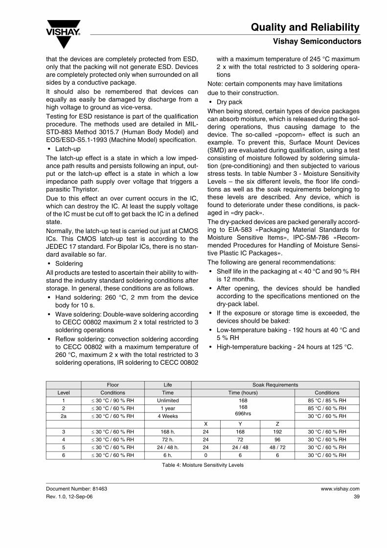
Note: certain components may have limitationsdue to their construction. • Dry packWhen being stored, certain types of device packagescan absorb moisture, which is released during the sol-dering operations, thus causing damage to thedevice. The so-called «popcorn» effect is such anexample. To prevent this, Surface Mount Devices(SMD) are evaluated during qualification, using a testconsisting of moisture followed by soldering simula-tion (pre-conditioning) and then subjected to variousstress tests. In table Number 3 - Moisture SensitivityLevels – the six different levels, the floor life condi-tions as well as the soak requirements belonging tothese levels are described. Any device, which isfound to deteriorate under these conditions, is pack-aged in «dry pack».The dry-packed devices are packed generally accord-ing to EIA-583 «Packaging Material Standards forMoisture Sensitive Items», IPC-SM-786 «Recom-mended Procedures for Handling of Moisture Sensi-tive Plastic IC Packages».The following are general recommendations: • Shelf life in the packaging at < 40 °C and 90 % RH
is 12 months. • After opening, the devices should be handled
according to the specifications mentioned on thedry-pack label.
• If the exposure or storage time is exceeded, thedevices should be baked:
• Low-temperature baking - 192 hours at 40 °C and5 % RH
• High-temperature backing - 24 hours at 125 °C.
Floor Life Soak Requirements
Level Conditions Time Time (hours) Conditions
1 ≤ 30 °C / 90 % RH Unlimited 168168
696hrs
85 °C / 85 % RH
2 ≤ 30 °C / 60 % RH 1 year 85 °C / 60 % RH
2a ≤ 30 °C / 60 % RH 4 Weeks 30 °C / 60 % RH
X Y Z
3 ≤ 30 °C / 60 % RH 168 h. 24 168 192 30 °C / 60 % RH
4 ≤ 30 °C / 60 % RH 72 h. 24 72 96 30 °C / 60 % RH
5 ≤ 30 °C / 60 % RH 24 / 48 h. 24 24 / 48 48 / 72 30 °C / 60 % RH
6 ≤ 30 °C / 60 % RH 6 h. 0 6 6 30 °C / 60 % RH
Table 4: Moisture Sensitivity Levels

www.vishay.com
40
Document Number: 81463
Rev. 1.0, 12-Sep-06
Quality and ReliabilityVishay Semiconductors
X = Default value of semiconductor manufac-turer’s exposure time (MET) between bake andbag plus the maximum time allowed out of thebag at the distributor’s facility. The actual timesmay be used rather than the default times, butthey must be used if they exceed the defaulttimes.
Y = Floor life of package after it is removed fromdry pack bag (level 8 after completion of bake).
Z = Total soak time for evaluation (X + Y).
Note: There are two possible floor lives and soaktimes in Level 5. The correct floor life will be deter-mined by the manufacturer and will be noted on thedry pack bag label per JEP 113.«Symbol and Labelsfor Moisture Sensitive Devices».

Quality and Reliability
Document Number: 81463
Rev. 1.0, 12-Sep-06
Vishay Semiconductors
www.vishay.com
41
Reliability & Statistics Glossary
DefinitionsAccelerated Life Test: A life test under conditionsthat are more severe than usual operating conditions.It is helpful, but not necessary, that a relationshipbetween test severity and the probability distributionof life be ascertainable.Acceleration Factor: Notation: f(t) = the time trans-formation from more severe test conditions to theusual conditions. The acceleration factor is f(t)/t. Thedifferential acceleration factor is df(t)/dt.Acceptance number: The largest numbers ofdefects that can occur in an acceptance samplingplan and still have the lot accepted.Acceptance Sampling Plan: An accept/reject testthe purpose of which is to accept or reject a lot ofitems or material based on random samples from thelot.Assessment: A critical appraisal including qualitativejudgements about an item, such as importance ofanalysis results, design criticality, and failure effect.Attribute (Inspection By): A term used to designatea method of measurement whereby units are exam-ined by noting the presence (or absence) of somecharacteristic or attribute in each of the units in thegroup under consideration and by counting how manyunits do (or do not) possess it. Inspection by attributescan be two kinds: either the unit of product is classi-fied simply as defective or not defective or the numberof defects in the unit of product is counted withrespect to a given requirement or set of requirements.Attribute Testing: Testing to evaluate whether or notan item possesses a specified attribute.Auger Electron Spectrometer: An instrument, thatidentifies elements on the surface of a sample. Itexcites the area of interest with an electron beam andobserves the resultant emitted Auger electrons.These electrons have the specific characteristics ofthe near surface elements. It is usually used to iden-tify very thin films, often surface contaminants.Availability (Operational Readiness): The probabil-ity that at any point in time the system is either oper-ating satisfactorily or ready to be placed in operationon demand when used under stated conditions.Average Outgoing Quality (AOQ): The averagequality of outgoing product after 100 % inspection ofrejected lot, with replacement by good units of alldefective units found in inspection.
Bathtub Curve: A plot of failure rate of an item(whether repairable or not) vs. time. The failure rateinitially decreases, then stays reasonably constant,then begins to rise rather rapidly. It has the shape ofbathtub. Not all items have this behavior.Bias: (1) The difference between the expected valueof an estimator and the value of the true parameter;(2) Applied voltage.Burn-in: The initial operation of an item to stabilize itscharacteristics and to minimize infant mortality in thefield.Confidence Interval: The interval within which it isasserted that the parameters of a probability distribu-tion lies.Confidence Level: Equals 1 - α where α = the risk (%).Corrective Action: A documented design, process,procedure, or materials change to correct the truecause of a failure. Part replacement with a like itemdoes not constitute appropriate corrective action.Rather, the action should make it impossible for thatfailure to happen again.Cumulative Distribution Function (CDF): The prob-ability that the random variable takes on any valueless than or equal to a value x, e.g. F(x) = CDF (x) = Pr (x ≤ X).Defect: A deviation of an item from some ideal state.The ideal state usually is given in a formal specifica-tion.Degradation: A gradual deterioration in performanceas a function of time.Derating: The intentional reduction of stress/strengthratio in the application of an item, usually for the pur-pose of reducing the occurrence of stress-related fail-ures.Duty Cycle: A specified operating time of an item, fol-lowed by a specified time of no operation.Early Failure Period: That period of life, after finalassembly, in which failures occur at an initially highrate because of the presence of defective parts andworkmanship. This definition applies to the first part ofthe bathtub curve for failure rate (infant mortality).EDX Spectrometer: Generally used with a scanningelectron microscope (SEM) to provide elementalanalysis of X-rays generated on the region being hitby the primary electron beam.Effectiveness: The capability of the system or deviceto perform its function.EOS – Electrical Overstress: The electrical stress-ing of electronic components beyond specifications.May be caused by ESD.

www.vishay.com
42
Document Number: 81463
Rev. 1.0, 12-Sep-06
Quality and ReliabilityVishay Semiconductors
ESD – Electrostatic Discharge: The transfer of elec-trostatic charge between bodies at different electro-static potentials caused by direct contact or inducedby an electrostatic field. Many electronic componentsare sensitive to ESD and will be degraded or fail.Expected Value: A statistical term. If x is a randomvariable and F (x) it its CDF, the E (x) = xdF (x), wherethe integration is over all x. For continuous variableswith a pfd, this reduces to E (x) = ∫ x pfd (x) dx. For dis-crete random variables with a pfd, this reduces to E (x) = Σxnp (xn) where the sum is over all n.Exponential Distribution: A 1-parameter distribution(λ > 0, t ≤ 0) with: pfd (t) = lexp (-λt); Cdf (t) 0 1 – exp (-λt); Sf (t) = exp (-λt) ; failure rate = λ; mean time-to-failure = 1/λ. This is theconstant failure-rate-distribution.Failure: The termination of the ability of an item to per-form its required function.Failure Analysis: The identification of the failuremode, the failure mechanism, and the cause (i.e.,defective soldering, design weakness, contamination,assembly techniques, etc.). Often includes physicaldissection.Failure, Catastrophic: A sudden change in the oper-ating characteristics of an item resulting in a completeloss of useful performance of the item.Failure, Degradation: A failure that occurs as a resultof a gradual or partial change in the operating charac-teristics of an item.Failure, Initial: The first failure to occur in use.Failure, Latent: A malfunction that occurs as a resultof a previous exposure to a condition that did notresult in an immediately detectable failure. Example:Latent ESD failure.Failure Mechanism: The mechanical, chemical, orother process that results in a failure.Failure Mode: The effect by which a failure isobserved. Generally, describes the way the failureoccurs and tells "how" with respect to operation.Failure Rate: (A) The conditional probability densitythat the item will fail just after time t, given the item hasnot failed up to time t; (B) The number of failures of anitem per unit measure of life (cycles, time, miles,events, etc.) as applicable for the item.Failure, Wearout: Any failure for which time of occur-rence is governed by rapidly increasing failure rate.FIT: Failure Unit; (also, Failures In Time) Failures per109 hours.Functional Failure: A failure whereby a device doesnot perform its intended function when the inputs orcontrols are correct.
Gaussian Distribution: A 2-parameter distributionwith:
Cdf (x) = guaf (x). SF (x) = gaufc (x). "Mean value ofx" u, "standard deviation of x" = σHazard Rate: Instantaneous failure rate.Hypothesis, Null: A hypothesis stating that there isno difference between some characteristics of theparent populations of several different samples, i.e.,that the samples came from similar populations.Infant Mortality: Premature catastrophic failuresoccurring at a much greater rate than during theperiod of useful life prior to the onset of substantialwear out.Inspection: The examination and testing of suppliesand services (including when appropriate, raw mate-rials, components, and intermediate assemblies) todetermine whether they conform to specified require-ments.Inspection by Attributes: Inspection whereby eitherthe unit of product or characteristics thereof is classi-fied simply as defective or not defective or the numberof defects in the unit of product is counted withrespect to a given requirement.Life Test: A test, usually of several items, made forthe purpose of estimating some characteristic(s) ofthe probability distribution of life.Lot: A group of units from a particular device typesubmitted at one time for inspection and / or testing.Lot Reject Rate (LRR): The lot reject rate is the per-centage of lots rejected form the lots evaluated.Lot Tolerance Percent Defective (LTPD): The per-cent defective which is to be accepted a minimum orarbitrary fraction of the time, or that percent defectivewhose probability of rejection is designated by b.Mean: (A) The arithmetic mean, the expected value;(B) As specifically modified and defined, e.g., har-monic mean (reciprocals), geometric mean (a prod-uct), logarithmic mean (logs).Mean Life: R(t)dt; where R(t) = the reliability of theitem; t = the interval over which the mean life isdesired, usually the useful life (longevity).Mean-Life-Between-Failures: The concept is thesame as mean life except that it is for repaired itemsand is the mean up-time of the item. The formula isthe same as for mean life except that R(t) is inter-preted as the distribution of up-times. Mean-Time-
pfd (x) 1
2πσ------------- e
12--- x u–
σ------------⎝ ⎠
⎛ ⎞ 2
⋅=

Quality and Reliability
Document Number: 81463
Rev. 1.0, 12-Sep-06
Vishay Semiconductors
www.vishay.com
43
Between-Failures (MTBF): For a particular interval,the total functioning life of a population of an itemdivided by the total number of failures within the pop-ulation during the measurement interval. The defini-tion holds for time, cycles, miles, events, or othermeasure of life units.Mean-Time-To-Failure (MTTF): See "Mean Life".Mean-Time-To-Repair (MTTR): The total correctivemaintenance time divided by the total number of cor-rective maintenance actions during a given period oftime.MTTR: = G(t)dt; where G(t) = Cdf of repair time; t = maximum allowed repair time, i.e., item is treatedas not repairable at this echelon and is discarded orsent to a higher echelon for repair.Operating Characteristic (OC) Curve: A curveshowing the relation between the probability of accep-tance and either lot quality or process quality, which-ever is applicable.Part Per Million (PPM): PPM is arrived at by multiply-ing the percentage defective by 10,000.Example: 0.1 % = 1,000 PPM.Population: The totality of the set of items, units,measurements, etc., real or conceptual, that is underconsideration.Probability Distribution: A mathematical functionwith specific properties, which describes the probabil-ity that a random variable will take on a value or set ofvalues. If the random variable is continuous and wellbehaved enough, there will be a pfd. If the randomvariable is discrete, there will be a pmf.Qualification: The entire process by which productsare obtained from manufacturers or distributors,examined and tested, and then identified on a Quali-fied Product List.Quality: A property which refers to the tendency of anitem to be made to specific specifications and/or thecustomer’s express needs. See current publicationsby Juran, Deming, Crosby, et al.Quality Assurance: A system of activities that pro-vides assurance that the overall quality control job isbeing done effectively. The system involves a con-tinuing evaluation of the adequacy and effectivenessof the overall quality control program with a view tohaving corrective measures initiated where neces-sary. For a specific product or service, this involvesverifications, audits, and the evaluation of the qualityfactors that affect the specification, productioninspection, and use of the product or service.
Quality Characteristics: Those properties of an itemor process, which can be measured, reviewed, orobserved and which are identified in the drawings,specifications, or contractual requirements. Reliabilitybecomes a quality characteristic when so defined.Quality Control (QC): The overall system of activitiesthat provides a quality of product or service, whichmeets the needs of users; also, the use of such a sys-tem.Random Samples: As commonly used in accep-tance sampling theory, the process of selecting sam-ple units in such a manner that all units underconsideration have the same probability of beingselected.Reliability: The probability that a device will functionwithout failure over a specified time period or amountof usage at stated conditions.Reliability Growth: Reliability growth is the effort, theresource commitment, to improve design, purchas-ing, production, and inspection procedures to improvethe reliability of a design.Risk: α : The probability of rejecting the null hypothe-sis falsely.Scanning Electron Microscope (SEM): An instru-ment which provides a visual image of the surfacefeatures of an item. It scans an electron beam overthe surface of a sample while held in a vacuum andcollects any of several resultant particles or energies.The SEM provides depth of field and resolution signif-icantly exceeding light microscopy and may be usedat magnifications exceeding 50,000 times.Screening Test: A test or combination of testsintended to remove unsatisfactory items or thoselikely to exhibit early failures.Significance: Results that show deviations betweenhypothesis and the observations used as a test of thehypothesis, greater than can be explained by randomvariation or chance alone, are called statistically sig-nificant.Significance Level: The probability that, if thehypothesis under test were true, a sample test statis-tic would be as bad as or worse than the observedtest statistic.SPC: Statistical Process Control.Storage Life (Shelf Life): The length of time an itemcan be stored under specified conditions and stillmeet specified requirements.Stress: A general and ambiguous term used as anextension of its meaning in mechanics as that whichcould cause failure. It does not distinguish between

www.vishay.com
44
Document Number: 81463
Rev. 1.0, 12-Sep-06
Quality and ReliabilityVishay Semiconductors
those things which cause permanent damage (deteri-oration) and those things which are not (in theabsence of failure).Variance: The average of the squares of the devia-tions of individual measurements from their average.It is a measure of dispersion of a random variable orof data.Wearout: The process of attribution which results inan increase of hazard rate with increasing age(cycles, time, miles, events, etc.) as applicable for theitem.
AbbreviationsAQL Acceptable Quality LevelCAR Corrective Action Report / RequestDIP Dual In-Line PackageECAP Electronic Circuit Analysis ProgramEMC Electro-Magnetic CompatibilityEMI Electro-Magnetic InterferenceEOS Electrical OverstressESD Electrostatic DischargeFAR Failure Analysis Report / RequestFIT (Failure In Time) Failure Unit; Failures /
109 hoursFMEA Failure Mode and Effects AnalysisFTA Fault Tree Analysish (t) Hazard RateLTPD Lot Tolerance Percent DefectiveMOS Metal Oxide SemiconductorMRB Material Review BoardMTBF Mean-Time-Between-FailuresMTTF Mean-Time-To-FailureMTTR Mean-Time-To-RepairPPM Parts Per MillionPRST Probability Ratio Sequential TestQA Quality AssuranceQC Quality ControlQPL Qualified Products ListRPM Reliability Planning and ManagementSCA Sneak Circuit AnalysisSEM Scanning Electron MicroscopeTW Wearout TimeZ (t) Hazard Rateλ Failure Rate (Lambda)