Embed Size (px)
Citation preview
Corning Specialty FiberProduct Information Sheets

Table of Contents High Bend / Bend Insensitive Fibers
Corning® HI 780 & 780 C Specialty Optical Fibers 1
Corning® HI 980 & RC HI 980 Specialty Optical Fibers 3
Corning® HI 1060 & RC HI 1060 Specialty Optical Fibers 5
Corning® HI 1060FLEX & RC HI 1060 FLEX Specialty Optical Fibers 7
Corning® RC 1300 and RC 1550 Specialty Optical Fibers 9
Erbium-Doped Fibers
Corning® HICER 98 Specialty Optical Fibers 11
Corning® ER Specialty Optical Fibers 13
High Temperature / Harsh Environment Fibers
Corning® Hermetic Single-mode and Multimode Specialty Optical Fibers 17
Corning® Mid-Temperature Specialty Optical Fibers 19
Corning® ClearCurve® Single-mode Mid-Temperature Specialty Optical Fibers 21 for Harsh Environments
Corning® ClearCurve® Multimode Mid-Temperature Specialty Optical Fibers 23 for Harsh Environments
Corning® ClearCurve® Multimode Mid-Temperature Specialty Optical Fibers 25 for Short Distance Networks
Special Single-Mode Fibers
Corning® RC SMF Specialty Optical Fibers 27
Corning® RGB 400 Specialty Optical Fibers 29
Corning® ClearCurve® Photonic Specialty Optical Fibers 31
Corning® SMF-28e+® Photonic Optical Fibers 33
Corning® ClearCurve® XB Specialty Optical Fibers 37
PANDA / Polarization Control Fibers
PANDA PM Specialty Optical Fibers 41
PANDA Flame Retardant Specialty Optical Fibers 45
PANDA High NA Specialty Optical Fibers 47
PANDA Bend Insensitive Specialty Optical Fibers 49
RGB PM Specialty Optical Fibers 51

Page 1
Corning® HI 780 & HI 780C Specialty Optical Fibers High Index / Bend Insensitive
Manufactured with Corning’s patented Outside Vapor Deposition (OVD) process, Corning® HI 780 Specialty Fiber offers world-class durability and reliability. When used as component pigtails, this fiber allows for efficient fiber coupling within photonic products. It also offers reduced bend attenuation due to its high core index of refraction. Corning® HI 780 Specialty Fiber is capable of operating with short wavelength laser and LED sources. Corning now offers a re-engineered version, HI 780C, which delivers non-adiabatic taper loss during component manufacturing. HI 780C is a coupler-optimized design that allows for steeper tapers and shorter couplers with lower losses.
Applications: · Low loss fused fiber couplers
· Component fiber for couplers, and other DWDM components
· Short wavelength laser and LED sources
· Sensors and gyroscopes
Features:
· Outstanding consistency and uniformity using Corning’s patented Outside Vapor Deposition (OVD) process
· Dual acrylate coating system provides excellent protection from microbend-induced attenuation and superior mechanical robustness
· Excellent geometry control
· High core index of refraction
· Efficient coupling
· High numerical aperture
M0100006 Issued: March 2010
Supersedes: January 2008
For low loss fused couplers, high performance components and small footprint assemblies
Page 2
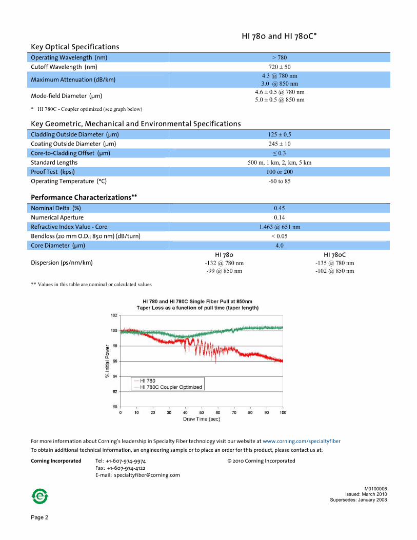
HI 780 and HI 780C* Key Optical Specifications Operating Wavelength (nm) > 780 Cutoff Wavelength (nm) 720 ± 50
Maximum Attenuation (dB/km) 4.3 @ 780 nm 3.0 @ 850 nm
Mode-field Diameter (µm) 4.6 ± 0.5 @ 780 nm 5.0 ± 0.5 @ 850 nm
* HI 780C - Coupler optimized (see graph below) Key Geometric, Mechanical and Environmental Specifications Cladding Outside Diameter (µm) 125 ± 0.5 Coating Outside Diameter (µm) 245 ± 10 Core-to-Cladding Offset (µm) ≤ 0.3 Standard Lengths 500 m, 1 km, 2, km, 5 km Proof Test (kpsi) 100 or 200 Operating Temperature (ºC) -60 to 85 Performance Characterizations** Nominal Delta (%) 0.45 Numerical Aperture 0.14 Refractive Index Value - Core 1.463 @ 651 nm Bendloss (20 mm O.D.; 850 nm) (dB/turn) < 0.05 Core Diameter (µm) 4.0
Dispersion (ps/nm/km) HI 780
-132 @ 780 nm -99 @ 850 nm
HI 780C -135 @ 780 nm -102 @ 850 nm
** Values in this table are nominal or calculated values
For more information about Corning’s leadership in Specialty Fiber technology visit our website at www.corning.com/specialtyfiber
To obtain additional technical information, an engineering sample or to place an order for this product, please contact us at: Corning Incorporated Tel: +1-607-974-9974 © 2010 Corning Incorporated Fax: +1-607-974-4122 E-mail: [email protected]
M0100006 Issued: March 2010
Supersedes: January 2008

Page 3
Corning® HI 980 & RC HI 980 Specialty Optical Fibers High Index / Bend Insensitive
Manufactured with Corning’s
patented Outside Vapor
Deposition (OVD) process,
Corning® HI 980 Specialty Fiber
offers world-class durability
and reliability. When used as
component pigtails, this fiber
allows for efficient fiber
coupling within photonic
products. It also offers reduced
bend attenuation due to its
high core index of refraction.
Applications: HI 980 · Single-mode performance at 980 nm and above · Component fiber for EDFAs, couplers, and other DWDM components · Pigtails for pump lasers · Gratings RC HI 980 · Component fiber for EDFAs, couplers, and other DWDM components · Pigtails for pump lasers
Features: HI 980 and RC HI 980 · Outstanding consistency and uniformity using Corning’s patented Outside
Vapor Deposition (OVD) process · Dual acrylate coating system provides excellent protection from
microbend-induced attenuation and superior mechanical robustness · Excellent geometry control · High core index of refraction · Mode-field diameter matched to erbium-doped fiber, allowing for efficient
coupling · High proof test for increased reliability in tight bend configurations · High numerical aperture · RC HI 980 provides 80 µm diameter for miniature packaging
M0100007 Issued: March 2010
Supersedes: August 2003
Industry standard for 980 pump pigtails for high performance components and small footprint assemblies

Page 4
HI 980 RC HI 980 Key Optical Specifications Operating Wavelength (nm) > 980 Cutoff Wavelength (nm) 930 ± 50 Maximum Attenuation (dB/km) ≤ 2.5 @ 980 nm Mode-field Diameter (µm) 4.2 ± 0.3 @ 980 nm
Key Geometric, Mechanical and Environmental Specifications Cladding Outside Diameter (µm) 125 ± 0.5 80 ± 1 Coating Outside Diameter (µm) 245 ± 10 165 ± 10 Core-to-Cladding Offset (µm) ≤ 0.3 ≤ 0.5 Standard Lengths 500 m, 1 km, 2, km, 5 km, 10 km Proof Test (kpsi) 100* or 200 Operating Temperature (°C) -60 to 85
*100 kpsi only available for RC HI980
Performance Characterizations** Nominal Delta (%) 1.0 Numerical Aperture 0.21 Refractive Index Value – Core 1.471 @ 651 nm Bendloss (20 mm O.D.; 1550 nm) (dB/turn) ≤ 0.01 Core Diameter (µm) 3.5 Dispersion (ps/nm/km) -63 @ 980 nm
** Values in this table are nominal or calculated values Typical Splice Loss RC SMF Fiber HI 980 Wavelength (nm) 1550 980 RC HI 980 (dB) 0.11 0.05 For more information about Corning’s leadership in Specialty Fiber technology visit our website at www.corning.com/specialtyfiber
To obtain additional technical information, an engineering sample or to place an order for this product, please contact us at: Corning Incorporated Tel: +1-607-974-9974 © 2010 Corning Incorporated Fax: +1-607-974-4122 E-mail: [email protected]
M0100007 Issued: February 2010
Supersedes: August 2003

Page 5
Corning® HI 1060 & RC HI 1060 Specialty Optical Fibers High Index / Bend Insensitive
Manufactured with Corning’s
patented Outside Vapor
Deposition (OVD) process,
Corning® HI 1060 Specialty
Fiber offers world-class
durability and reliability. When
used as component pigtails,
this fiber allows for efficient
fiber coupling within photonic
products.
Applications: HI 1060 · Photonic products and fused fiber couplers
· Component fiber for EDFAs, couplers, and other DWDM components
· Laser diode pigtails
· Gratings
RC HI 1060 · Component fiber for EDFAs, couplers, and other DWDM components
· Pigtails for pump lasers
Features: HI 1060 and RC HI 1060 · Outstanding consistency and uniformity using Corning’s patented
Outside Vapor Deposition (OVD) process
· Dual acrylate coating system provides excellent protection from microbend-induced attenuation and superior mechanical robustness
· Excellent geometry control
· High core index of refraction
· Efficient coupling
· High numerical aperture
· RC HI 1060 offers 80 µm diameter for miniature packaging
M0100008
Issued: March 2010 Supersedes: August 2003
Industry standard for 980 pump pigtails for high performance components and small footprint assemblies

Page 6
HI 1060 RC HI 1060 Key Optical Specifications Operating Wavelength (nm) > 980
Maximum Attenuation (dB/km) 2.1 @ 980 nm 1.5 @ 1060 nm
Cutoff Wavelength (nm) 920 ± 50
Mode-field Diameter (µm) 5.9 ± 0.3 @ 980 nm 6.2 ± 0.3 @ 1060 nm
Key Geometric, Mechanical and Environmental Specifications Cladding Outside Diameter (µm) 125 ± 0.5 80 ± 1 Coating Outside Diameter (µm) 245 ± 10 165 ± 10 Core-to-Cladding Offset (µm) ≤ 0.3 ≤ 0.5 Standard Lengths 500 m, 1 km, 2 km, 5 km, 10 km* Proof Test (kpsi) 100 or 200 Operating Temperature (°C) -60 to 85 *10 km lengths only available for HI 1060
Performance Characterizations** Nominal Delta (%) 0.48 Numerical Aperture 0.14 Refractive Index Value – Core 1.464 @ 651 nm
Dispersion (ps/nm/km) -53 @ 980 nm -38 @ 1060 nm
Bendloss (@ 20 mm O.D.; 1150 nm) (dB/turn) ≤ 0.01 Core Diameter (µm) 5.3
** Values in this table are nominal or calculated values Typical Splice Loss HI 1060 RC PANDA PM 980 SMF-28e+ Fiber RC SMF Fiber Wavelength (nm) 1550 980 1550 1550 RC HI 1060 (dB) 0.04 0.07 0.16 0.08 For more information about Corning’s leadership in Specialty Fiber technology visit our website at www.corning.com/specialtyfiber
To obtain additional technical information, an engineering sample or to place an order for this product, please contact us at: Corning Incorporated Tel: +1-607-974-9974 © 2010 Corning Incorporated Fax: +1-607-974-4122 E-mail: [email protected]
M0100008 Issued: March 2010
Supersedes: August 2003
Page 7
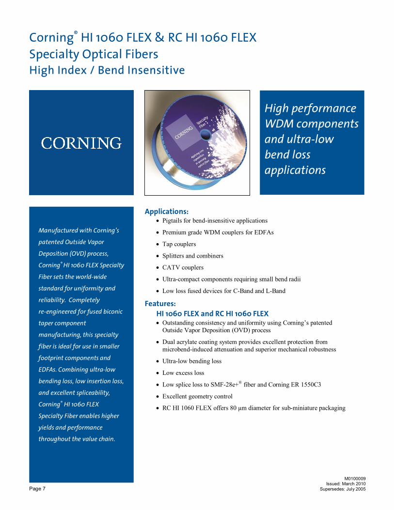
Corning® HI 1060 FLEX & RC HI 1060 FLEX Specialty Optical Fibers High Index / Bend Insensitive
Manufactured with Corning’s
patented Outside Vapor
Deposition (OVD) process,
Corning® HI 1060 FLEX Specialty
Fiber sets the world-wide
standard for uniformity and
reliability. Completely
re-engineered for fused biconic
taper component
manufacturing, this specialty
fiber is ideal for use in smaller
footprint components and
EDFAs. Combining ultra-low
bending loss, low insertion loss,
and excellent spliceability,
Corning® HI 1060 FLEX
Specialty Fiber enables higher
yields and performance
throughout the value chain.
Applications: · Pigtails for bend-insensitive applications
· Premium grade WDM couplers for EDFAs
· Tap couplers
· Splitters and combiners
· CATV couplers
· Ultra-compact components requiring small bend radii
· Low loss fused devices for C-Band and L-Band
Features: HI 1060 FLEX and RC HI 1060 FLEX · Outstanding consistency and uniformity using Corning’s patented
Outside Vapor Deposition (OVD) process
· Dual acrylate coating system provides excellent protection from microbend-induced attenuation and superior mechanical robustness
· Ultra-low bending loss
· Low excess loss
· Low splice loss to SMF-28e+® fiber and Corning ER 1550C3
· Excellent geometry control
· RC HI 1060 FLEX offers 80 µm diameter for sub-miniature packaging
M0100009 Issued: March 2010
Supersedes: July 2005
High performance WDM components and ultra-low bend loss applications

Page 8
HI 1060 FLEX RC HI 1060 FLEX Key Optical Specifications Operating Wavelength (nm) > 980
Maximum Attenuation (dB/km) ≤ 2.5 @ 980 nm ≤ 1.0 @ 1550 nm
Cutoff Wavelength (nm) 930 ± 40 nm
Mode-field Diameter (µm) 4.0 ± 0.3 @ 980 nm 6.3 ± 0.3 @ 1550 nm
Key Geometric, Mechanical and Environmental Specifications Cladding Outside Diameter (µm) 125 ± 0.5 80 ± 1 Coating Outside Diameter (µm) 245 ± 10 165 ± 10 Core-to-Cladding Offset (µm) ≤ 0.3 ≤ 0.5 Standard Lengths 500 m, 1 km, 2 km, 5 km, 10 km Proof Test (kpsi) 100 or 200 Operating Temperature (°C) -60 to 85
Performance Characterizations* Nominal Delta (%) 1.0 Numerical Aperture 0.22 Refractive Index Value – Core 1.472 @ 651 nm
Dispersion (ps/nm/km) -65 @ 980 nm -50 @ 1060 nm
Bendloss (@ 20 mm O.D., 1550 nm) (dB/turn) ≤ 0.01 Core Diameter (µm) 3.4
* Values in this table are nominal or calculated values Typical Splice HI 1060 FLEX SMF-28e+® RC SMF ER 1550C3 HI 1060 HI 980 PM 980 Wavelength (nm) 1550 1550 1500 1550 980 980 980 HI 1060 FLEX (dB) 0.03 0.07 --- 0.03 0.06 0.04 0.09 RC HI 1060 FLEX (dB) --- 0.22 0.12 0.08 --- --- --- For more information about Corning’s leadership in Specialty Fiber technology visit our website at www.corning.com/specialtyfiber
To obtain additional technical information, an engineering sample or to place an order for this product, please contact us at: Corning Incorporated Tel: +1-607-974-9974 © 2010 Corning Incorporated Fax: +1-607-974-4122 E-mail: [email protected]
M0100009 Issued: March 2010
Supersedes: July 2005

Page 9
Corning® RC 1300 and RC 1550 Specialty Optical Fibers High Index / Bend Insensitive
Manufactured with Corning’s
patented Outside Vapor
Deposition (OVD) process,
Corning® RC 1300 and RC 1550
Specialty Fibers offer world-
class durability and reliability
with a reduced cladding of 80
µm (compared to the industry
standard of 125 µm) . The
reduced cladding allows
extremely tight fiber coiling
with low bend loss, enabling a
range of system designs not
possible with standard
specialty fibers.
Applications: · Devices requiring extremely tight bend radius coils
· Dense wavelength division multiplexing (DWDM) components
· Compact optical circuits
· Sensors
Features:
· Outstanding consistency and uniformity using Corning’s patented Outside Vapor Deposition (OVD) process
· Dual acrylate coating system provides excellent protection from microbend-induced attenuation and superior mechanical robustness
· Reduced cladding (80 µm)
· Excellent geometry control
· High core index of refraction
· Efficient coupling
M0100010 Issued: March 2010
Supersedes: January 2008
Reduced cladding fiber for small size coils and assemblies
Page 10
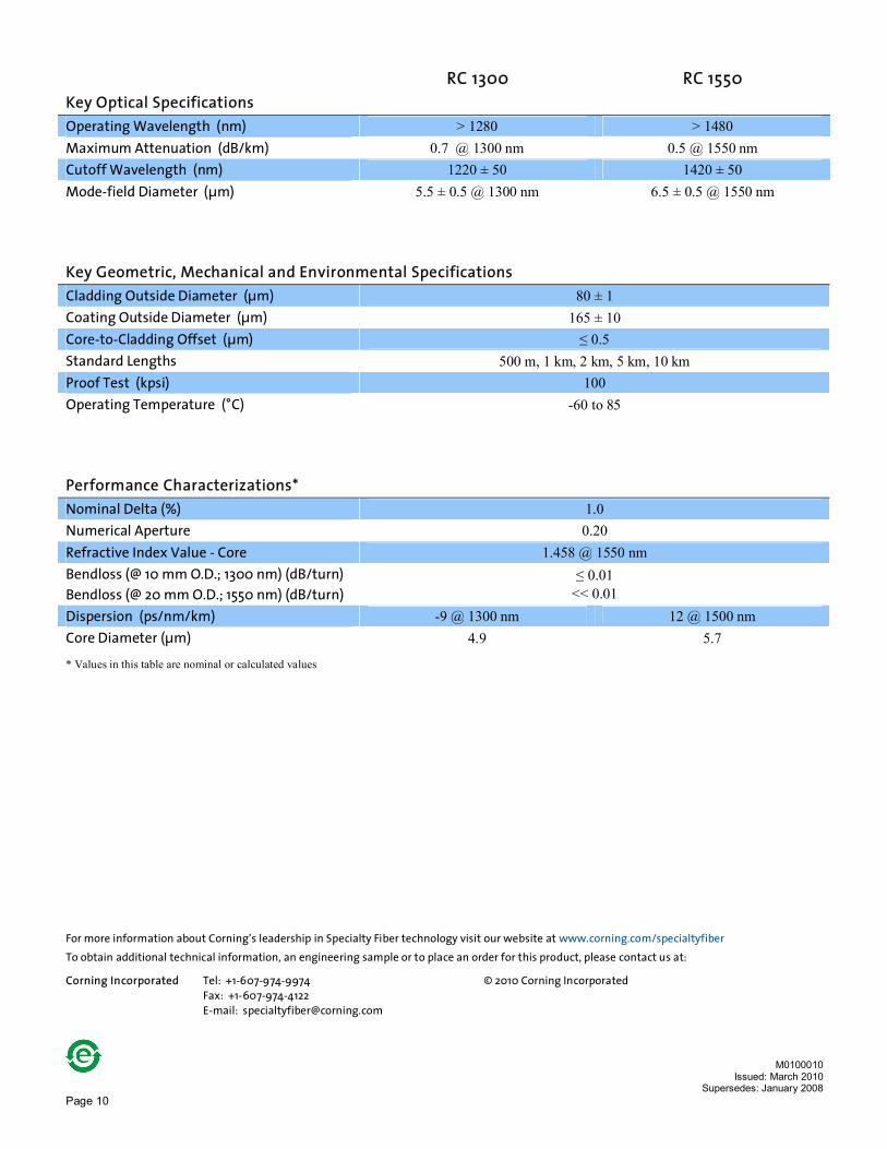
RC 1300 RC 1550 Key Optical Specifications Operating Wavelength (nm) > 1280 > 1480 Maximum Attenuation (dB/km) 0.7 @ 1300 nm 0.5 @ 1550 nm Cutoff Wavelength (nm) 1220 ± 50 1420 ± 50 Mode-field Diameter (µm) 5.5 ± 0.5 @ 1300 nm 6.5 ± 0.5 @ 1550 nm
Key Geometric, Mechanical and Environmental Specifications Cladding Outside Diameter (µm) 80 ± 1 Coating Outside Diameter (µm) 165 ± 10 Core-to-Cladding Offset (µm) ≤ 0.5 Standard Lengths 500 m, 1 km, 2 km, 5 km, 10 km Proof Test (kpsi) 100 Operating Temperature (°C) -60 to 85
Performance Characterizations* Nominal Delta (%) 1.0 Numerical Aperture 0.20 Refractive Index Value - Core 1.458 @ 1550 nm Bendloss (@ 10 mm O.D.; 1300 nm) (dB/turn) Bendloss (@ 20 mm O.D.; 1550 nm) (dB/turn)
≤ 0.01 << 0.01
Dispersion (ps/nm/km) -9 @ 1300 nm 12 @ 1500 nm Core Diameter (µm) 4.9 5.7
* Values in this table are nominal or calculated values For more information about Corning’s leadership in Specialty Fiber technology visit our website at www.corning.com/specialtyfiber
To obtain additional technical information, an engineering sample or to place an order for this product, please contact us at: Corning Incorporated Tel: +1-607-974-9974 © 2010 Corning Incorporated Fax: +1-607-974-4122 E-mail: [email protected]
M0100010 Issued: March 2010
Supersedes: January 2008

Page 11
HICER 98 Splice-Optimized Coupler Fiber
Corning® HICER 98 Specialty Optical Fiber High Index Coupler Fiber
A new addition to the Corning® FBT coupler optimized fiber family; HICER 98 is the ideal fiber for applications where a single splice recipe is required. Designed for splicing flexibility to industry standard Erbium and single-mode fibers, HICER 98 benefits from Corning’s Outside Vapor Deposition (OVD) process consistency, allowing for large quantities of fiber with identical composition which minimizes coupler turning time.
Applications:
n Couplers and Optical Components
n WDM Couplers
n CATV Couplers
n Splitters and Combiners
Features:
n Splice-Optimized to Industry Standard Erbium and Single-mode Fibers
n Versatile Splicing with a Single Splice Recipe
n No New Splice Recipe Required
n Outstanding Consistency and Uniformity Using Corning’s Patented
Outside Vapor Deposition (OVD) Process
n Dual Acrylate Coating System Provides Excellent Protection from
Microbend Induced Attenuation and Superior Mechanical Robustness
M0100041 Issued: September 2010

Page 12
HICER 98 Key Optical Specifications
Operating Wavelength (nm) 980, 1550 Cutoff Wavelength (nm) ≤ 960 Maximum Attenuation (dB/km) ≤ 2.5 @ 980 nm
≤ 1.0 @ 1550 nm Mode-field Diameter (µm) 5.0 ± 0.3 @ 980 nm
7.5 ± 0.75 @ 1550 nm
Key Geometric, Mechanical and Environmental Specifications
Cladding Outside Diameter (µm) 125 ± 0.5 Coating Outside Diameter (µm) 245 ± 10 Core-to-Cladding Offset (µm) ≤ 0.3 Proof Test (kpsi) 200 Operating Temperature (°C) -60 to 85 Coating Dual UV Acrylate Recommended Minimum Bending Radius (mm) 30
Performance Characterizations*
Nominal Delta/Profile (%) 0.68 Numerical Aperture 0.17 Refractive Index Value – Core 1.467 @ 651 nm Dispersion (ps/nm/km) -55.4 @ 980 nm
0.2 @1550 nm Core Diameter (µm) 4.5
* Values in this table are nominal or calculated values
For more information about Corning’s leadership in Specialty Fiber technology visit our website at www.corning.com/specialtyfiber
To obtain additional technical information, an engineering sample or to place an order for this product, please contact us at: Corning Incorporated t + 1-607-974-9974 © 2010 Corning Incorporated f +1-607-974-4122 [email protected]
M0100041 Issued: September 2010

Page 13
Corning® ER Specialty Optical Fibers Erbium-Doped Fibers
Manufactured with Corning’s patented Outside Vapor Deposition (OVD) process, Corning® ER Specialty Fibers set the world standard for uniformity and reliability. Corning offers Erbium-doped fibers with or without hermetic coating. The hermetic coating offers significant advantage with respect to mechanical reliability and resistance to hydrogen induced optical attenuation degradation. These Erbium-doped fibers have a proven track record in state-of-the-art optical amplifiers, and exhibit consistently low splice loss when coupled with fibers such as Corning® HI 1060 FLEX, Corning® HI 980 and Corning® SMF-28e+® Optical Fiber. Erbium-doped fibers designs are available for conventional C-band, L-band and Reduced Clad (80 µm) applications.
Applications: · Single and multi-wavelength optical amplifiers (EDFA)
· Digital and analog systems
· CATV amplifiers
Features:
· Outstanding consistency and uniformity using Corning’s patented Outside Vapor Deposition (OVD) process
· OVD manufacturing consistency provides repeatability for gain spectrum allowing for the reduction of lot qualifications in amplifier deployment
· Hermetic coating for increased environmental stability and reliability
· Dual acrylate coating system provides excellent protection from microbend-induced attenuation and superior mechanical robustness
· Short and long cutoff wavelength C-band versions available
· Excellent geometry control
· Mode-field diameter designed to match Corning® High Index Specialty Fiber, allowing for efficient coupling with an EDFA
M0200012 Issued: March 2010
Supersedes: January 2008
For use in Optical Amplifiers and Fiber Lasers
Page 14
ER 1550C3 ER 1550C3 LC RC ER 1550C3
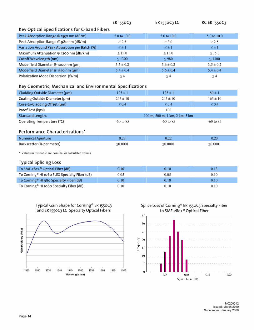
Key Optical Specifications for C-band Fibers Peak Absorption Range @ 1530 nm (dB/m) 5.0 to 10.0 5.0 to 10.0 5.0 to 10.0 Peak Absorption Range @ 980 nm (dB/m) ³ 2.5 ³ 3.0 ³ 2.5 Variation Around Peak Absorption per Batch (%) ≤ ± 1 ≤ ± 1 ≤ ± 1 Maximum Attenuation @ 1200 nm (dB/km) ≤ 15.0 ≤ 15.0 ≤ 15.0 Cutoff Wavelength (nm) ≤ 1300 ≤ 980 ≤ 1300 Mode-field Diameter @ 1000 nm (µm) 3.5 ± 0.2 3.6 ± 0.2 3.5 ± 0.2 Mode-field Diameter @ 1550 nm (µm) 5.4 ± 0.4 5.6 ± 0.4 5.4 ± 0.4 Polarization Mode Dispersion (fs/m) ≤ 4 ≤ 4 ≤ 4
Key Geometric, Mechanical and Environmental Specifications Cladding Outside Diameter (µm) 125 ± 1 125 ± 1 80 ± 1 Coating Outside Diameter (µm) 245 ± 10 245 ± 10 165 ± 10 Core-to-Cladding Offset (µm) ≤ 0.4 ≤ 0.4 ≤ 0.4 Proof Test (kpsi) 100 Standard Lengths 100 m, 500 m, 1 km, 2 km, 5 km Operating Temperature (°C) -60 to 85 -60 to 85 -60 to 85
Performance Characterizations* Numerical Aperture 0.23 0.22 0.23 Backscatter (% per meter) ≤0.0001 ≤0.0001 ≤0.0001
* Values in this table are nominal or calculated values
Typical Splicing Loss To SMF-28e+® Optical Fiber (dB) 0.10 0.10 0.13 To Corning® HI 1060 FLEX Specialty Fiber (dB) 0.05 0.05 0.10 To Corning® HI 980 Specialty Fiber (dB) 0.10 0.10 0.10 To Corning® HI 1060 Specialty Fiber (dB) 0.10 0.10 0.10
Typical Gain Shape for Corning® ER 1550C3 and ER 1550C3 LC Specialty Optical Fibers
Splice Loss of Corning® ER 1550C3 Specialty Fiber to SMF-28e+® Optical Fiber
M0200012
Issued: March 2010 Supersedes: January 2008

Page 15
ER 1600L3 RC ER 1600L3
Key Optical Specifications for L-band Fibers Peak Absorption Range @ 1530 nm (dB/m) 18.0 to 29.0 Variation Around Peak Absorption per Batch (%) ≤ ± 1 Maximum Attenuation @ 1200 nm (dB/km) ≤ 15.0 Cutoff Wavelength (nm) ≤ 1400 Mode-field Diameter @ 1550 nm (µm) 5.5 ± 0.3 Polarization Mode Dispersion (fs/m) ≤ 5
Key Geometric, Mechanical and Environmental Specifications Cladding Outside Diameter (µm) 125 ± 1 80 ± 1 Coating Outside Diameter (µm) 245 ± 10 165 ± 10 Core-to-Cladding Offset (µm) ≤ 0.4 Proof Test (kpsi) 100 Standard Lengths 100 m, 500 m, 1 km, 2 km, 5 km Operating Temperature (ºC) -60 to 85
Performance Characterizations* Numerical Aperture 0.23 Backscatter (% per meter) ≤0.0002 Non-linear Index of Refraction (n2) (m2/W) ≤ 3.5 x 10⁻²⁰ Effective Area (Aeff) (µm2) 22.5 ± 2.5 * Values in this table are nominal or calculated values
Typical Splicing Loss To SMF-28e+® Optical Fiber (dB) 0.10 0.10 To Corning® HI 980 Specialty Fiber (dB) 0.10 0.10 To Corning® HI 1060 Specialty Fiber (dB) 0.10 0.10
Typical Gain Shape for Corning® ER 1600L3 Specialty Fiber Splice Loss of Corning® ER 1600L3 Specialty Fiber
to SMF-28e+® Optical Fiber
M0200012
Issued: March 2010 Supersedes: January 2008

Page 16
Corning’s Outside Vapor Deposition Process Corning’s patented Outside Vapor Deposition (OVD) manufacturing process creates the most consistent fiber in the world. Producing 100 percent synthetic glass, the OVD process greatly reduces, if not eliminates, impurities that can affect fiber performance. It also provides greater degree of control and flexibility in fiber design. Corning is now using seventh generation outside vapor deposition technology, the most advanced in the world today.
Importance of Erbium-doped Fiber Uniformity Perhaps the most critical parameter for Erbium-doped fiber in high performance amplifiers is the uniformity of the gain spectrum from one coil to the next. Because Corning produces fiber via the OVD process, it is by far the most uniform in the world. Individual starting core glass blanks are able to generate multiple fiber draw preforms of equivalent composition and profile, ensuring many hundreds of kilometers of fiber with equivalent properties. Other companies utilizing processes like MCVD require recipe replication for each draw preform, which imparts inherent variability. In fact, no other company can address customer requirements with the same level of experience, capacity and precision manufacturing as Corning. In typical high-performance amplifiers built with our Erbium-doped fiber, gain consistency is maximized due to spectral uniformity of the fiber, eliminating the need for frequent adjustments to gain flattening filter design. Variations in gain spectrum and pump power requirements are greatly reduced, which makes for a more predictable amplifier manufacturing process and translates directly to lower costs for customers.
Spectral Uniformity of Corning® ER 1550C3 Specialty Fiber Spectral Uniformity of Corning® ER 1600L3 Specialty Fiber
Corning’s ER Design Options Corning’s low cutoff design Type 3 C-band (ER 1550C3 LC), is specifically designed for EDFAs that do not use tight coiling. This fiber ensures single-mode attribute at 980 nm wavelength without coiling. Another benefit of the low cutoff C-band fiber is enhanced 980/1550 absorption ratio which can give enhanced pump power utilization and noise figure in specific EDFA designs. This product is compatible with other Erbium-doped fibers on the market. Corning’s high cutoff C-band product (ER 1550C3), which can be coiled to maintain less than 980 nm cutoff, has an optimized profile for demonstrated performance improvements in efficiency as lower Erbium ion concentrations can be used to achieve similar signal band peak absorption (i.e. lower ion-ion interaction). The spectral characteristics of ER 1550C3 LC can be matched to ER 1550C3 while providing equivalent spectral uniformity performance. ER 1550C3 LC fiber offers customers a highly uniform OVD processed fiber alternative to established low cutoff designs, resulting in greater manufacturing control and procurement flexibility.
The Corning Advantage All Erbium-doped fibers are not equal. Corning understands the each customer’s amplifier design varies and their need for custom requirements and gain spectrums are paramount. By combining Corning’s fundamental ER fiber processing and reliability features with our customer’s unique design needs, Corning is leading the way in low cost EDFA designs. With the confidence of tens of thousands of kilometers experience, make Corning® Erbium-doped fiber your next choice, and feel the advantage. For more information about Corning’s leadership in Specialty Fiber technology visit our website at www.corning.com/specialtyfiber To obtain additional technical information, an engineering sample or to place an order for this product, please contact us at: Corning Incorporated Tel: +1-607-974-9974 © 2010 Corning Incorporated Fax: +1-607-974-4122 E-mail: [email protected] M0200012
Issued: March 2010 Supersedes: January 2008

Page 17
Corning® Hermetic Single-mode and Multimode Specialty Optical Fibers
Corning’s Hermetic Single-mode and Multimode Fibers are designed for applications requiring improved fatigue resistance, high useable strength and excellent resistance to hydrogen permeation into optical fibers. Corning’s specially designed hermetic layer provides a protective barrier to help shield the glass from exposure to hydrogen, water, and corrosive chemicals while maintaining optical qualities comparable to standard fibers. The properties of the hermetic layer increase the fatigue performance of the fiber five times compared with non-hermetic fibers. Corning’s hermetic layer is a thin layer of amorphous carbon that is bonded to the glass surface of the optical fiber. The fiber is manufactured with Corning’s patented Outside Vapor Deposition (OVD) process. The Hermetic Single-mode and Multimode Specialty Fibers offer high reliability and consistent performance for a variety of applications.
Applications: · Hydrogen-rich environments
· Long distance undersea links
· Towed arrays
· Sensors
· Increased fatigue resistance for tight bend applications
Features:
· No hydrogen aging at room temperature to 85°C
· Low attenuation
· Outstanding consistency and uniformity using Corning’s patented Outside Vapor Deposition (OVD) process
· Efficient coupling
· Dual acrylate coating system provides excellent protection from microbend-induced attenuation and superior mechanical robustness
· Fibers include:
- Single-mode: optimized for 1310 nm and 1550 nm wavelengths
- Multimode: optimized for 850 nm and 1300 nm wavelengths
- Inquire for other glasses
M0300013 Issued: March 2010
Supersedes: January 2008

Page 18
SMFHA MMFHA Key Optical Specifications Operating Wavelength (nm) 1310, 1550 850, 1300
Maximum Attenuation (dB/km) 0.4 @ 1310 nm 0.25 @ 1550 nm
2.5 @ 850 nm 0.7 @ 1300 nm
Cutoff Wavelength (nm) ≤ 1290 ---
Mode-field Diameter (µm) 9.2 ± 0.4 @ 1310 nm 10.4 ± 0.5 @ 1550 nm ---
Bandwidth (MHz-km) --- ³ 500
Key Geometric, Mechanical and Environmental Specifications Hermetic + Dual layer UV-curable acrylate Cladding Outside Diameter (µm) 125 ± 0.7 125 ± 2.0 Coating Outside Diameter (µm) 245 ± 10 245 ± 10 Core-to-Cladding Offset (µm) ≤ 0.5 ≤ 1.5 Core Diameter (µm) 8.2 (nominal) 50 ± 2.5 Standard Lengths 500 m, 1 km, 2 km, 5 km, 10 km* Proof Test (kpsi) 200 Operating Temperature (°C) -60 to 85 * 10 km lengths available for SMFHA only
Performance Characterizations* Numerical Aperture 0.12 0.20 Refractive Index Difference (%) 0.36 1.0 Fatigue Resistance Parameter (nd) > 100 > 100
Effective Group Index of Refraction (Neff) 1.4675 @ 1310 nm 1.4681 @ 1550 nm ---
* Values in this table are nominal or calculated values
Hydrogen Resistance (Single-mode only) Test Condition Results 21 Day Exposure to Hydrogen @ 11 ATM, 85°C ≤ 0.2 dB/km induced attenuation at 1240 nm Note: Expected attenuation at 1310 nm and 1550 nm for 30 year life at 5 atmospheres Hydrogen and 10°C is ≤ 0.05 dB/km. Corning offers fiber stripping and splicing support for Hermetically-coated fibers. Reference: White Paper “Corning’s Hermetically Coated Erbium-doped Specialty Fibers” by Kohli and Glaesemann For more information about Corning’s leadership in Specialty Fiber technology visit our website at www.corning.com/specialtyfiber
To obtain additional technical information, an engineering sample or to place an order for this product, please contact us at: Corning Incorporated Tel: +1-607-974-9974 © 2010 Corning Incorporated Fax: +1-607-974-4122 E-mail: [email protected]
M0300013 Issued: March 2010
Supersedes: January 2008

Page 19
Single-mode and multimode optical fiber with mid-temperature acrylate-based coatings
Corning® Mid-Temperature Specialty Optical Fibers
Corning Specialty Fiber portfolio has expanded and now contains optical
fiber coatings for operations up to 180 °C. While these coatings provide
the ability to operate at elevated temperatures, they are also acrylate-
based for ease of use and handling. When combined with Corning’s
extensive range of optical glass properties, the introduction of mid-
temperature coatings opens a new dimension for the uses of fiber optics.
With the addition of Corning’s distinctive hermetic layer, these mid-
temperature fibers offer improved hydrogen resistance and fatigue
performance in mid-temperature ranges.
Applications: n Fiber Sensing and Data Transmission for:
• Aerospace and Defense • Medical • Structural Health Monitoring • Down-Hole Drilling
Features: n Acrylate-base for ease of handling n Rated for up to 180 °C n Fully qualified at 165 °C n Hermetic coating (optional) for protection against hydrogen induced
attenuation increase and improved fatigue resistance n Consistent strength over time at elevated temperatures n Multimode fiber is made with a graded index refractive index profile
for increased performance
M0300035 Issued: February 2013
Supersedes: September 2012
Inquire for information about the application of mid-temperature coatings on glasses with optical properties that match your application or custom need.

Page 20
SMA-C MM50A-C*** Key Optical Specifications
Operating Wavelength (nm) 1310, 1550 850, 1060, 1300 Cutoff Wavelength (nm) ≤ 1290 n/a Maximum Attenuation (dB/km) 0.38 @ 1310 nm
0.24 @ 1550 nm 2.5 @ 850 nm
0.7 @ 1300 nm Mode-field Diameter (µm) 9.2 ± 0.4 @ 1310 nm
10.4 ± 0.5 @ 1550 nm n/a
Bandwidth @ 850 nm and 1300 nm (MHz-km) n/a ≥ 500# Numerical Aperture 0.12 (nominal) 0.20 ± 0.015 # Higher bandwidth MM fibers are available with the ClearCurve® Multimode mid-Temperature fibers (M0300120)
Key Geometric, Mechanical and Environmental Specifications
Core Diameter (µm) 8.2 (nominal) 50 ± 2.5 Cladding Outside Diameter (µm) 125 ± 1.0 125 ± 2.0 Coating Outside Diameter (µm) 245 ± 10 245 ± 10* Core-to-Cladding Offset (µm) ≤ 0.5 ≤ 1.5 Standard Lengths** 500 m, 1 km, 2 km, 5 km Proof Test (kpsi) 100 100 Operating Temperature (°C) -60 to 150 or 180 **** -60 to 150 or 180 **** Coating Mid-Temperature Acrylate
Optional Hermetic Layer Mid-Temperature Acrylate
Optional Hermetic Layer * 200 ± 10 µm also available for 150 °C only
** Contact Corning Incorporated for longer lengths
**** MM50-MT and MM50H-MT contain graded index Refractive Index profile
*** 180 °C product also fully qualified at 165 °C
SMA-C or MM50A-C Single-Mode or Multimode Optical Fiber with:
Category Definition Product Code
A Hermetic Indicator Non Hermetic
Hermetic
(blank)
H
C Mid-temperature
Acrylate Coating Type
150 °C
180 °C
MT
XMT
For more information about Corning’s leadership in Specialty Fiber technology visit our website at www.corning.com/specialtyfiber
To obtain additional technical information, an engineering sample or to place an order for this product, please contact us at: Corning Incorporated t +1-607-974-9974 © 2012 Corning Incorporated f +1-607-974-4122 e [email protected]
M0300035 Issued: February 2013
Supersedes: September 2012

Page 21
Single-mode bend insensitive optical fiber with mid-temperature acrylate-based coatings
Corning® ClearCurve® Single-Mode Mid-Temperature Specialty Optical Fibers for Harsh Environments
The Corning® ClearCurve® Single-mode bend insensitive family of fibers
now includes higher temperature capability. For use at temperatures up to
180 °C and beyond, these acrylate-based fibers deliver the best macro bend
performance in the industry with ease of use and handling; benefiting
sensing systems operating in harsh environments.
Applications:
n Fiber Sensing and Data Transmission with tight bend requirements for:
• Aerospace and Defense • Medical • Structural Health Monitoring
• Down-Hole Drilling
Features:
n Acrylate-base for ease of handling
n Rated for up to 180 °C
n Fully qualified at 165 °C
n Test data available for 150 °C - 200 °C temperature range
n Hermetic coating (optional) for protection against hydrogen induced attenuation increase and improved fatigue resistance
n Consistent strength over time at elevated temperatures
n A set of fibers designed to meet your specific needs with recommended minimum bending radii of 5 mm, 7.5 mm and 10 mm
n Exceeding the stringent bend performance requirements of ITU-Recommendations G.657.B3, G657.A2/B2, G657.A1 respectively
n Fully compliant with ITU-Recommendations G652.D
n Compatible with Corning® SMF-28e® and SMF-28e+® fibers
M0300052 Issued: February 2013 Supersedes: July 2112
Inquire for information about the application of mid-temperature coatings on glasses with optical properties that match your application or custom need.

Page 22
SMBIA-5-C SMBIA-7.5-C SMBIA-10-C Key Optical Specifications
Operating Wavelength (nm) 1310, 1550 1310, 1550 1310, 1550 Cable Cutoff Wavelength (nm) ≤ 1260 ≤ 1260 ≤ 1260 Maximum Attenuation (dB/km) @ 1310 nm @ 1550 nm
0.38 0.24
0.38 0.24
0.38 0.24
Mode-field Diameter (µm) @ 1310 nm @ 1550 nm
8.6 ± 0.4 9.65 ± 0.5
8.6 ± 0.4 9.6 ± 0.5
8.6 ± 0.4 9.8 ± 0.5
Key Geometric, Mechanical and Environmental Specifications
Cladding Outside Diameter (µm) 125 ± 1.0 Coating Outside Diameter (µm) 245 ± 10* Core-to-Cladding Offset (µm) ≤ 0.5 Standard Lengths 500 m, 1 km, 2 km, 5 km Proof Test (kpsi) 100 Operating Temperature (°C) -60 to 150 or 180** Coating Mid-Temperature Acrylate
Optional Hermetic Layer
* 200 ± 10 µm also available for 150 °C only
** 180 °C product also fully qualified at 165 °C
Performance Characteristics (values in this table are nominal or calculated)
Numerical Aperture 0.12 0.12 0.12 Bend Loss (X mm radius; 1 turn) (dB/turn) @ 1550 nm @ 1625 nm
≤ 0.10 ≤ 0.30
≤ 0.40 ≤ 0.80
≤ 0.50 ≤ 1.50
Recommended Minimum Bending Radius (mm) 5 7.5 10
SMBIA-B-C Single-Mode Bend Insensitive Optical Fiber with:
Category Definition Product Code
A Hermetic Indicator Non Hermetic
Hermetic (blank)
H
B Minimum Bend Radius (mm) 5
7.5 10
5 7.5 10
C Mid-temperature
Acrylate Coating Type 150 °C 180 °C
MT XMT
For more information about Corning’s leadership in Specialty Fiber technology visit our website at www.corning.com/specialtyfiber
To obtain additional technical information, an engineering sample or to place an order for this product, please contact us at: Corning Incorporated t +1-607-974-9974 © 2012 Corning Incorporated f +1-607-974-4122 e [email protected]
M0300052 Issued: February 2013
Supersedes: September 2112

Page 23
Multimode bend insensitive optical fiber with mid-temperature acrylate-based coatings
NEW! Corning® ClearCurve® Multimode Mid-Temperature Specialty Optical Fibers for Harsh Environments
The Corning® ClearCurve® Multimode bend insensitive fiber now includes
even higher temperature and higher bandwidth capability. For use at
temperatures up to 180 °C and beyond, this acrylate-based fiber delivers
incredible macro bend performance with ease of use and handling;
benefiting sensing systems operating in harsh environments.
Applications:
n Fiber Sensing and Data Transmission with tight bend and/or high bandwidth requirements for:
• Aerospace and Defense
• Structural Health Monitoring
• Down-Hole Drilling
Features:
n Acrylate-base for ease of handling
n Rated for up to 180 °C (fully qualified at 165 °C)
n Test data available for 150 °C - 200 °C temperature range
n Available OM2 / OM3 / OM4 bandwidths
n Hermetic coating (optional) for protection against hydrogen induced attenuation increase and improved fatigue resistance
n Consistent strength over time at elevated temperatures
n A fiber designed to meet your specific needs with recommended minimum bending radius of 7.5 mm
n Fully compliant with ITU-Recommendations G651.1, and compatible with current optical fibers and practices
M0300120 Issued: February 2013
Supersedes: September 2012
Inquire for information about the application of mid-temperature coatings on glasses with optical properties that match your application or custom need.

Page 24
MM50BIA-B-C Key Optical Specifications Operating Wavelength (nm) 850, 1060, 1300 Cable Cutoff Wavelength (nm) N/A Maximum Attenuation (dB/km) @ 850 nm @ 1300 nm
2.5 0.7
Numerical Aperture 0.20 ± 0.015 Bandwidth (MHz-km) See table below
MHz-Km OM2 OM3 OM4
High Performance EMB 850 nm 950 2000 4700
Legacy Performance OFL 850 nm 700 1500 3500
1300 nm 500 500 500 Key Geometric, Mechanical and Environmental Specifications Core Diameter (µm) 50 ± 2.5 Cladding Outside Diameter (µm) 125 ± 2.0 Coating Outside Diameter (µm) 245 ± 10* Core-to-Cladding Offset (µm) ≤ 1.5 Standard Lengths 500 m, 1 km, 2 km, 5 km Proof Test (kpsi) 100 Operating Temperature (°C) -60 to 150 or 180** Coating Mid-Temperature Acrylate
Optional Hermetic Layer * 200 ± 10 µm also available for 150 °C only ** 180 °C product also fully qualified at 165 °C
Performance Characteristics (values in this table are nominal or calculated) Refractive Index Profile Graded Index Bend Loss (7.5 mm radius; 2 turns) (total induced attenuation) @ 850 nm @ 1300 nm
≤ 0.2 ≤ 0.50
Recommended Minimum Bending Radius (mm) 7.5
MM50BIA-B-C Multimode Bend Insensitive Optical Fiber with:
Category Definition Product Code
A Hermetic Indicator Non Hermetic
Hermetic (blank)
H
B Bandwidth OM2
OM3
OM4
OM2
OM3
OM4
C Mid-temperature
Acrylate Coating Type
150 °C
180 °C
MT
XMT
For more information about Corning’s leadership in Specialty Fiber technology visit our website at www.corning.com/specialtyfiber
To obtain additional technical information, an engineering sample or to place an order for this product, please contact us at: Corning Incorporated t +1-607-974-9974 © 2012 Corning Incorporated f +1-607-974-4122 e [email protected] M0300120
Issued: February 2013 Supersedes: September 2012

Page 25
Multimode
Specialty Optical
Fiber for Short
Distance Networks
NEW! Corning® ClearCurve® Multimode Mid-Temperature Specialty Optical Fibers for Short Distance Networks
Corning® ClearCurve® Multimode Specialty Optical Fiber for short distance networks is the newest addition to the Corning Specialty Fiber family. This fiber utilizes Corning® ClearCurve® technology to create a perfect fiber for industrial applications that contain tight bends and a need for align-able fibers that withstand elevated temperatures.
Applications:
n Aerospace and Defense
n Automotive
n Avionics
n Distributed Fiber Sensors
Features:
n Low bend loss for applications that require tight bending
n Relaxed packaging alignment tolerances through high numerical aperture (0.29 NA) and a large core size of 80 µm
n Optimized for use with VCSEL technology
n Rated for use up to 180 °C
n Acrylate based coating for ease of handling
n Multimode fiber is made with a graded index refractive index profile for increased performance
n Hermetic coating (optional) for protection against hydrogen induced attenuation increase and improved fatigue resistance
M0300121 Issued: February 2013
Supersedes: December 2012
Inquire for information about the application of mid-temperature coatings on glasses with optical properties that match your application or custom need.

Page 26
MM80BIA-C Key Optical Specifications
Operating Wavelength (nm) 850 Maximum Attenuation (dB/km) ≤ 3.5 @ 850 nm Numerical Aperture 0.29 ± 0.015 Bandwidth (MHz/km) ≥ 300
Key Geometric, Mechanical and Environmental Specifications
Core Diameter (µm) 80 ± 4.0 Cladding Outside Diameter (µm) 125 ± 2.0 Coating Outside Diameter (µm) 200* ± 10 or 245 ± 10 Core-to-Cladding Offset (µm) ≤ 1.5 Proof Test (kpsi) 100 Operating Temperature (°C) -60 to 150 or 180 Coating Mid-Temperature Acrylate
Optional Hermetic Layer * Available for 150° C only
Performance Characteristics (values in this table are nominal or calculated)
MacroBend Loss @ 850 nm (5 mm radius; 1 turn) Typical induced attenuation1 (dB) Typical induced attenuation2 (dB)
≤ 0.1 ≤ 0.2
1 Measured using 50 µm encircled flux launch, representative of typical consumer grade VCSEL transceiver launch condition.
2 Measured using 62.5 µm encircled flux launch, representative of worst case consumer grade VCSEL transceiver launch condition.
MM80BIA-C Multimode 80 µm Bend insensitive Optical Fiber with:
Category Definition Product Code
A Hermetic Indicator Non-Hermetic
Hermetic
(blank)
H
C Mid-temperature
Acrylate Coating Type
150 °C
180 °C
MT
XMT
For more information about Corning’s leadership in Specialty Fiber technology visit our website at www.corning.com/specialtyfiber
To obtain additional technical information, an engineering sample or to place an order for this product, please contact us at: Corning Incorporated t +1-607-974-9974 © 2012 Corning Incorporated f +1-607-974-4122 e [email protected]
M0300121 Issued: February 2013
Supersedes: December 2012

Page 27
Corning® RC SMF Specialty Optical Fiber
Manufactured with
Corning’s patented Outside
Vapor Deposition (OVD)
process, and based on
decades of experience in
specialty fiber development,
Corning® RC SMF Specialty
Fiber sets the industry
standard for consistent
geometric properties, high
mechanical reliability and efficient splicing.
Applications: · Low-loss miniature fused devices for C-band and L-band
· Ultra-compact components requiring small bend radii
· Pigtails in bend insensitive applications
· Sensors
Features: · Outstanding consistency and uniformity using Corning’s patented Outside
Vapor Deposition (OVD) process
· Dual acrylate coating system provides excellent protection from microbend-induced attenuation and superior mechanical robustness
· Ultra-tight specifications
· World-class reliability support for handling and deployment
· Technical support for splicing to 125 µm products
· Ultra-low splice loss to SMF-28e+®
· 80 µm diameter for miniature packaging
· Low bending loss
· Excellent geometry control
M0400015 Issued: March 2010
Supersedes: September 2006
Low loss fused components for EDFA and small bend radius applications

Page 28
RC SMF Key Optical Specifications Operating Wavelength (nm) > 1300 Maximum Attenuation @ 1310 nm (dB/km) 0.7 Maximum Attenuation @ 1550 nm (dB/km) 0.5 Cutoff Wavelength (nm) ≤ 1290 Coiled Cutoff at 80 mm Diameter (nm) 1210 ± 60 Coiled Cutoff at 32 mm Diameter (nm) 1140 ± 60 Mode-field Diameter @ 1310 nm (µm) 9.2 ± 0.3 Mode-field Diameter @ 1550 nm (µm) 10.4 ± 0.8
Key Geometric, Mechanical and Environmental Specifications Cladding Outside Diameter (µm) 80 ± 1 Coating Outside Diameter (µm) 165 ± 10 Core-to-Cladding Offset (µm) ≤ 0.5 Standard Lengths 500 m, 1 km, 2 km, 5 km, 10 km Proof Test (kpsi) 100 or 200 Operating Temperature (°C) -60 to 85
Performance Characterizations* Nominal Delta (%) 0.36 Numerical Aperture 0.12 Bend Loss (20 mm O.D.; 1550 nm) (dB/turn) ≤ 0.1 Core Diameter (µm) 8.0 * Values in this table are nominal or calculated values Typical Splice Loss SMF-28e+® Fiber RC HI 1060 RC PANDA PM 1550 RC HI 1060 FLEX RC HI 980 Wavelength (nm) 1550 1550 1550 1550 980 RC SMF Fiber (dB) 0.05 0.08 0.09 0.12 0.11 For more information about Corning’s leadership in Specialty Fiber technology visit our website at www.corning.com/specialtyfiber
To obtain additional technical information, an engineering sample or to place an order for this product, please contact us at: Corning Incorporated Tel: +1-607-974-9974 © 2010 Corning Incorporated Fax: +1-607-974-4122 E-mail: [email protected]
M0400015 Issued: February 2010
Supersedes: September 2006

Page 29
Corning® RGB 400 Specialty Optical Fiber
Corning RGB 400 Specialty Fiber is a single-mode fiber that is optimized for visible operating wavelength applications. The fiber’s short cut-off wavelength design enables single-mode operation in the visible wavelength range. Outside Vapor Deposition (OVD) processing is used to fabricate this fiber, providing consistent geometric properties and high strength. In addition to exceptional performance as a single-mode visible fiber, the design is also optimized to produce low loss fused biconic tapered couplers.
Applications: · Blue lasers
· Sensors
· Photolithography
· Red-Green-Blue components
· Couplers
· Diode pigtails
· High resolution display
Features:
· Outstanding consistency and uniformity using Corning’s patented Outside Vapor Deposition (OVD) process
· Dual acrylate coating system provides excellent protection from microbend-induced attenuation and superior mechanical robustness
· Profile optimized for adiabatic taper loss
· Excellent geometry control
· High reliability
M0400016 Issued: March 2010
Supersedes: May 2006
Optimized for visible light spectral range applications
Page 30
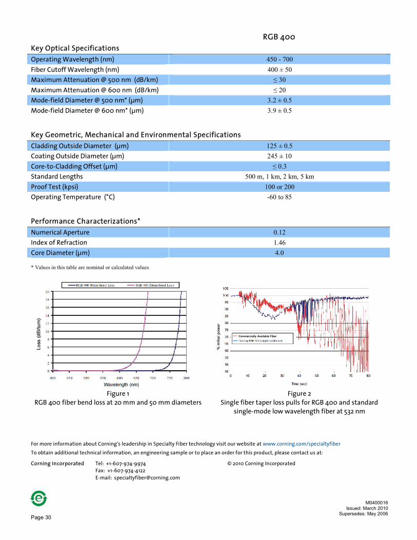
RGB 400 Key Optical Specifications Operating Wavelength (nm) 450 - 700 Fiber Cutoff Wavelength (nm) 400 ± 50 Maximum Attenuation @ 500 nm (dB/km) ≤ 30 Maximum Attenuation @ 600 nm (dB/km) ≤ 20 Mode-field Diameter @ 500 nm* (µm) 3.2 ± 0.5 Mode-field Diameter @ 600 nm* (µm) 3.9 ± 0.5
Key Geometric, Mechanical and Environmental Specifications Cladding Outside Diameter (µm) 125 ± 0.5 Coating Outside Diameter (µm) 245 ± 10 Core-to-Cladding Offset (µm) ≤ 0.3 Standard Lengths 500 m, 1 km, 2 km, 5 km Proof Test (kpsi) 100 or 200 Operating Temperature (°C) -60 to 85
Performance Characterizations* Numerical Aperture 0.12 Index of Refraction 1.46 Core Diameter (µm) 4.0 * Values in this table are nominal or calculated values
Figure 1
RGB 400 fiber bend loss at 20 mm and 50 mm diameters Figure 2
Single fiber taper loss pulls for RGB 400 and standard single-mode low wavelength fiber at 532 nm
For more information about Corning’s leadership in Specialty Fiber technology visit our website at www.corning.com/specialtyfiber
To obtain additional technical information, an engineering sample or to place an order for this product, please contact us at: Corning Incorporated Tel: +1-607-974-9974 © 2010 Corning Incorporated Fax: +1-607-974-4122 E-mail: [email protected]
M0400016 Issued: March 2010
Supersedes: May 2006
Commercially Available Fiber

Page 31
Bendable, spliceable, reliable and coupler optimized
NEW! Corning® ClearCurve® Photonic Specialty Optical Fibers
Specially designed to meet the growing demands for smaller footprints, Corning Introduces the NEW ClearCurve® Photonic Specialty Optical Fiber. This fiber was designed using Corning's patented ClearCurve® technology to give ultra-low bend loss performance. Created with tighter geometrical and mechanical specifications, this fiber enables consistent, reliable and low loss splicing. ClearCurve® Photonic Fiber was developed with an optical profile ideal for making couplers.
Corning® ClearCurve® Photonic Specialty Optical Fiber is optimized for use in Photonic Components, paving the way for you to reliably and consistently enable information to go faster, further and "smarter" in a smaller space.
Applications:
n Designed specifically for photonic components in small package sizes
n Very tight bend requirements
Features:
n 10 mm bend radius
n Low bend loss
n Tighter geometrical control
n High reliability enhanced by 200 kpsi
n FBT coupler friendly
M0400122 Issued: March 2012
Satisfying the need of Photonic component manufacturers for a single fiber optimized to provide low bend loss, tight geometrical control, high mechanical reliability and good coupler performance.

Page 32
ClearCurve® Photonic Key Optical Specifications
Operating Wavelength (nm) 1550 Cutoff Wavelength (nm) ≤ 1450 Maximum Attenuation (dB/km) 0.3 @ 1550 nm Mode-field Diameter (µm) 9.65 ± 0.5 @ 1550 nm
Key Geometric, Mechanical and Environmental Specifications
Cladding Outside Diameter (µm) 125 ± 0.5 Coating Outside Diameter (µm) 245 ± 10 Core-to-Cladding Concentricity (µm) ≤ 0.3 Standard Lengths 500 m, 1 km, 2 km, 5 km, 10 km Proof Test (kpsi) 200 Operating Temperature (°C) -60 to 85
Coating Dual Coat Acrylate
(Optional Hermetic Layer) Recommended Minimum Bending Radius (mm) 10
Performance Characteristics (values in this table are nominal or calculated)
Nominal Delta/Profile (%) 0.51 Numerical Aperture 0.15 Refractive Index Value – Core 1.464 @ 651 nm Dispersion (ps/nm/km) 18.2 @ 1550 nm
Bend Loss (@ 20 mm OD) (dB/m) 0.4 @ 1550 nm 1.0 @ 1625 nm
Core Diameter (µm) 9.4
For more information about Corning’s leadership in Specialty Fiber technology visit our website at www.corning.com/specialtyfiber
To obtain additional technical information, an engineering sample or to place an order for this product, please contact us at: Corning Incorporated t +1-607-974-9974 © 2012 Corning Incorporated f +1-607-974-4122 e [email protected]
M0400122 Issued: March 2012

Page 33
Corning® SMF-28e+® Photonic Optical Fiber
Corning’s SMF28e+® photonic fiber provides
further evidence of Corning’s long history of
service to original equipment
manufacturers (OEMs). This fiber’s attributes are
specifically customized for optical connectorization
and component applications, allowing
OEMs to reduce manufacturing costs,
standardize processes, and improve performance.
Applications: · Connectors
· EDFA
· Couplers
· Pigtails
· DWDM components
· Other components
Features: · Industry-leading optical and geometry specifications
· Exceptional performance and splice-ability
· Suitable for all transmission systems and fully compatible with SMF-28e+® optical fiber, the world’s most widely demanded full-spectrum fiber
· In compliance with, or exceeds the industry’s most stringent requirements including:
§ ITU-T Recommendations G.652 (Tables A, B, C & D) § IEC Specifications 60793-2-50 Type B1.3 § TIA/EIA 492-CAAB § Telcordia Generic Requirements GR-20-Core § ISO 11801 OS2
· Improved macro-bend specification from less than 0.05 dB to less than 0.03 dB, allowing better handling and ease of installation
· Tighter zero dispersion wavelength specification
· New coating for improved micro-bending
· Smaller coating outside diameter (242 µm nominal) for improved usage in ribbon applications
M1100025 Issued: April 2013
Supersedes: March 2010
A full spectrum fiber for components and assemblies with tighter geometry for more consistent splicing

Page 34
SMF-28e+® Photonic Optical Specifications Fiber Cutoff Wavelength (λcf) ≤ 1305 nm
Maximum Attenuation
Wavelength (nm) 1310
1383 ± 3** 1490 1550 1625
Maximum Value* (dB/km) ≤ 0.35 ≤ 0.35 ≤ 0.24 ≤ 0.20 ≤ 0.23
* Maximum specified attenuation value available within the stated ranges ** Attenuation post-hydrogen aging according to IEC 60793-2-50 Section C.5 for B.1.3 fibers.
Mode-field Diameter Wavelength (nm)
1310 1550
MFD (µm) 9.2 ± 0.4 10.4 ± 0.5
Dispersion Wavelength (nm)
1550 1625
Dispersion Value [ps/(nm·km)] ≤ 18.0 ≤ 22.0
Zero Dispersion Wavelength (λ0): 1304 nm ≤ λ0 1324 nm Zero Dispersion Slope (So): ≤ 0.088 ps/(nm2•km) Polarization Mode Dispersion (PMD) PMD Link Design Value Maximum Individual Fiber
Value (ps/√km) ≤ 0.06*
≤ 0.1
* Complies with IEC 60794-3: 2001, Section 5.5, Method 1, September 2001
The PMD link design is a term used to describe the PMD of concatenated lengths of fiber (also known as PMD0). This value represents a statistical upper limit for total PMD. Individual PMD values may change when fiber is cabled. Corning’s fiber specification supports network design requirements for 0.5 ps/√km maximum PMD.
Point Discontinuity Wavelength (nm)
1310 1550
Point Discontinuity (dB) ≤ 0.05 ≤ 0.05
M1100025 Issued: April 2013
Supersedes: March 2010

Page 35
SMF-28e+® Photonic Key Geometric, Mechanical and Environmental Specifications Cladding Diameter (µm) 125.0 ± 0.3 Core-Clad Concentricity (µm) ≤ 0.3 Cladding Non-Circularity (%) ≤ 0.7 Core Diameter (µm) 8.2 Coating Diameter (µm) 242 ± 5 Coating-Cladding Concentricity (µm) < 12 Coloring Diameter* (µm) 250 +15/-9 Fiber Curl (m) ³ 5.0 radius of curvature
* If applicable
Environmental Test Test Condition Induced Attenuation
1310 nm, 1550 nm & 1625 (dB/km)
Temperature Dependence (°C) -60 to 85 * ≤ 0.05 Temperature-Humidity Cycling (°C) -10 to 85 * up to 98% RH ≤ 0.05 Water Immersion (°C) 23 * ± 2 ≤ 0.05 Dry Heat Soak (°C) 85 * ± 2 ≤ 0.05 Damp Heat (°C) 85 * at 85% RH ≤ 0.05 Operating Temperature Range (°C) -60 to 85 Proof Test (kpsi) ³ 200 Lengths Available up to 50.4 km per spool
* Reference temperature: 23°C
Performance Characterizations* Numerical Aperture 0.12 Refractive Index Difference (%) 0.36
Effective Group Index of Refraction (Neff) 1.4670 @ 1310 nm 1.4677 @ 1550 nm
Fatigue Resistance Parameter (Nd) 20
Coating Strip Force Dry: 0.6 lb. (3N) Wet 14 day room temperature: 0.6 lb. (3N)
Rayleigh Backscatter Coefficient -77 dB @ 1310 nm -82 dB @1550 nm
Macrobend Loss Mandrel Diameter (mm)
32 50 50 60
Number of Turns 1
100 100 100
Wavelength 1550 1310 1550 1625
Induced Attenuation** (dB) ≤ 0.03 ≤ 0.03 ≤ 0.03 ≤ 0.03
* Values in this table are nominal or calculated values
** The induced attenuation due to fiber wrapped around a mandrel of a specified diameter.
M1100025 Issued: April 2013
Supersedes: March 2010

Page 36
The Single-Mode Fiber for Connectors and Components
Corning uses its legendary geometry control and quality leadership to manufacture SMF-28e+® photonic fiber. We focus on tailoring product attributes that allow OEMs to minimize scrap and overall insertion loss while improving active and splice performance. Through precise manufacturing techniques, we assure geometric performance along the entire length of fiber while maintaining nominal mode-field performance.
We proof stress the entire length of SMF-28e+® photonic fiber to ³ 200 kpsi, which provides OEMs with increased reliability and reduced handling concerns. In addition, we specify a fiber cutoff wavelength of 1280 nm, enabling operability at both 1310 nm and 1550 nm in bare fiber applications. Designed for Versatility and Performance
For better understanding of the applicable value to customers, Corning has completed studies using active and passive alignment techniques as well as modeled results. This research shows that significant splice performance improvement can result from focusing on nominal geometry performance and reducing deviation of a fiber’s core-clad concentricity, cladding diameter, cladding non-circularity and fiber curl. This improvement minimizes high-loss outliers and reduces the average splice loss, contributing to maximized OEM process efficiencies.
Corning manufactures the family of SMF-28e+® fibers using an Outside Vapor Deposition (OVD) process, which produces a totally synthetic, ultra-pure fiber. As a result, Corning fibers have consistent geometric properties, high strength, and low attenuation. OEMs can count on Corning SMF-28e+® photonic fiber to deliver excellent performance and reliability, reel after reel. Measurement methods comply with ITU recommendations G650, IEC 60793-1, and Telcordia GR20-CORE.
Formulas
Dispersion:
( )úúû
ù
êêë
é-»llll 3
4
00
4SD ps/(nm•km)
For 1200 nm ≤ λ ≤ 1625 nm Cladding Non Circularity:
1001 xgDiameterMaxCladdingDiameterMinCladdin
CladdingNonCladding
úû
ùêë
é-=
-
For more information about Corning’s leadership in Specialty Fiber technology visit our website at www.corning.com/specialtyfiber
To obtain additional technical information, an engineering sample or to place an order for this product, please contact us at: Corning Incorporated Tel: +1-607-974-9974 © 2010 Corning Incorporated Fax: +1-607-974-4122 E-mail: [email protected]
M1100025 Issued: April 2013
Supersedes: March 2010

Page 37
Corning® ClearCurve® XB Specialty Optical Fiber
Corning’s ClearCurve® XB fiber is a full-spectrum optical fiber with improved macro-bend performance compared to legacy single-mode fibers. Products of all types are constantly decreasing their size and becoming more complex. Having the ability to place fibers in increasingly smaller footprints without performance degradation is crucial to keeping the optical loss budgets low. The contribution by bend loss to the overall loss budget increases as the amount of fiber that is deployed in the bent state increases. Having a fiber that is designed for low bend loss makes these new smaller products a reality.
Applications: · Bend sensitive applications
· Footprint reduction
· Small size and integrated EDFA’s
· Couplers
· Pigtails/patchcords
Features: · Low bend loss design
· Fully compatible with legacy fibers
· Ease of handling and splice ability of standard single mode fibers
· Economical bend loss performance
· Optical attenuation that is flat across the C & L-Bands
· 200 kpsi proof test for higher mechanical reliability in small bend scenarios
· Fully compliant with the following standards:
§ ITU-T G.652.D § ITU-T G.657.A1
M1100026 Issued: August 2010
Supersedes: March 2010
Reduced footprint components and bend sensitive applications

Page 38
ClearCurve® XB Specialty Optical Fiber Optical Specifications Cable Cutoff Wavelength (λcf) (nm) =≤ 1260
Maximum Attenuation
Wavelength (nm) 1310 1550 1625
Maximum Value* (dB/km) 0.33 - 0.35 0.19 - 0.20 0.20 - 0.23
* Maximum specified attenuation value available within the stated ranges ** Attenuation post-hydrogen aging according to IEC 60793-2-50 Section C.5 for B.1.3 fibers.
Mode-field Diameter Wavelength (nm)
1310 1550
MFD (µm) 8.6 ± 0.4 9.8 ± 0.5
Dispersion Wavelength (nm)
1550 1625
Dispersion Value [ps/(nm·km)] ≤ 18.0 ≤ 22.0
Zero Dispersion Wavelength (λ0): 1304 nm ≤ λ0 1324 nm Zero Dispersion Slope (So): ≤ 0.089 ps/(nm2•km) Polarization Mode Dispersion (PMD) Maximum Individual Fiber
Value (ps/√km) ≤ 0.1
Point Discontinuity Wavelength (nm)
1310 1550
Point Discontinuity (dB) ≤ 0.05 ≤ 0.05
Key Geometric, Mechanical and Environmental Specifications Cladding Diameter (µm) 125.0 ± 0.7 Core-Clad Concentricity (µm) ≤ 0.5 Cladding Non-Circularity (%) ≤ 0.7 Coating Diameter (µm) 242 ± 5 Coating-Cladding Concentricity (µm) < 12 Coloring Diameter* (µm) 250 +15/-9 Fiber Curl (m) ³ 4.0 radius of curvature
* If applicable
Environmental Test Test Condition Induced Attenuation
1310 nm, 1550 nm & 1625 (dB/km)
Temperature Dependence (°C) -60 to 85 * ≤ 0.05 Temperature-Humidity Cycling (°C) -10 to 85 * up to 98% RH ≤ 0.05 Water Immersion (°C) 23 * ± 2 ≤ 0.05 Dry Heat Soak (°C) 85 * ± 2 ≤ 0.05 Damp Heat (°C) 85 * at 85% RH ≤ 0.05 Operating Temperature Range (°C) -60 to 85 Proof Test (kpsi) ³ 200 Lengths Available up to 50.4 km per spool
* Reference temperature: 23°C
M1100026 Issued: August 2010
Supersedes: March 2010

Page 39
ClearCurve® XB Specialty Optical Fiber Performance Characterizations* Index of Refraction (Core) 1.45 Numerical Aperture 0.13 Macrobend Loss
Mandrel Diameter (mm) 20 20
Number of Turns 1 1
Wavelength (nm) 1625 1550
Induced Attenuation** (dB) 1.5 0.5
* Values in this table are nominal or calculated values
** The induced attenuation due to fiber wrapped around a mandrel of a specified diameter.
M1100026 Issued: August 2010
Supersedes: March 2010

Page 40
For more information about Corning’s leadership in Specialty Fiber technology visit our website at www.corning.com/specialtyfiber
To obtain additional technical information, an engineering sample or to place an order for this product, please contact us at: Corning Incorporated Tel: +1-607-974-9974 © 2010 Corning Incorporated Fax: +1-607-974-4122 E-mail: [email protected]
M1100026 Issued: August 2010
Supersedes: March 2010

Page 41
PANDA PM Specialty Optical Fibers
PANDA PM Specialty Fibers are designed with the best polarization maintaining properties, and are the industry standard in the world today. The fibers offer low attenuation and excellent birefringence for high performance applications. Available in a wide range of standard operating wavelengths up to 1550 nm, and with a variety of coating designs, PANDA PM Specialty Fibers are optimal for high performance polarization retaining fiber applications. This field-proven fiber supports high growth applications, and performs well over a wide temperature range.
M0500017 Issued: November 2013
Supersedes: December 2012
High Performance Polarization Maintaining Fibers
Applications: · High performance transmission laser pigtails
· Polarization-based modulators
· High data rate communications systems
· Polarization-sensitive components
· Raman amplifiers
· Fiber optic sensors, gyroscopes and instrumentation
Features: · Extremely high birefringence
· Excellent polarization maintaining properties
· Low attenuation
· Single-mode designs from 400 nm – 1550 nm
· Dual-layer UV acrylate and 900 µm polyester-elastomer coatings available
· Low sensitivity to bending-induced attenuation
· Low splice loss
· PANDA PM Fibers available: - High Numerical Aperture - Reduced claddings - Low birefringence - Erbium-doped - Dispersion shifted - Polyimide and flame retardant coatings are also available

Page 42
PANDA PM Specialty Fibers
PM 1550 PM14XX PM 1300 PM 980 PM 850 PM 630 PM 480 PM 400 Key Optical Specifications For all coatings Wavelength (nm) 1550 1400-1490 1300 980 850 630 480 410
Mode-field Diameter (µm) 10.5 ± 0.5 9.8 ± 0.5 9.0 ± 0.5 6.6 ± 0.5 5.5 ± 0.5 4.5 ± 0.5 4.0 ± 0.5 3.5 ± 0.5
Beat Length Range (mm) 3.0-5.0 2.8-4.7 2.5-4.0 1.5-2.7 1.0-2.0 ≤ 2.0 ≤ 2.0 ≤ 1.7 Maximum Cross Talk at 100 m (dB) -30 -30 -30 -30 -30 -30 -30 -30* Typical Cross Talk at 4 m (dB) -40 -40 -40 -40 -40 -40 -40 -40 Cutoff Wavelength (nm) 1300-1440 1260-1380 1130-1270 870-950 650-800 520-620 400-470 330-400 Maximum Attenuation (dB/km) 0.5 1.0 1.0 2.5 3.0 12 30 ≤ 50
* PM 400 Cross Talk is ≤ -30dB/100 m at 410 nm and 480 nm measurement wavelengths
Key Geometric, Mechanical and Environmental Specifications (-U25D) UV/UV Acrylate Part Number PM 15-U25D PM 14-U25D PM 13-U25D PM 98-U25D PM 85-U25D PM 63-U25D PM 48-U25D PM40-U25D Core-to-Cladding Offset (µm) ≤ 0.5 Coating Outer Diameter (µm) 245 ± 15 Cladding Outer Diameter (µm) 125 ± 1 Standard Lengths* 100 m, 200 m, 300 m, 400 m, 500 m, 1 km Proof Test (kpsi) 100 (200 optional) Operating Temperature (°C) -40 to 85
Key Geometric, Mechanical and Environmental Specifications (-U40D) UV/UV Acrylate Part Number PM 15-U40D PM 14-U40D PM 13-U40D PM 98-U40D PM 85-U40D PM 63-U40D PM 48-U40D PM 40-U40D Core-to-Cladding Offset (µm) ≤ 0.5 Coating Outer Diameter (µm) 400 ± 15 Cladding Outer Diameter (µm) 125 ± 1 Standard Lengths* 100 m, 200 m, 300 m, 400 m, 500 m, 1 km Proof Test (kpsi) 100 (200 optional) Operating Temperature (°C) -40 to 85
Key Geometric, Mechanical and Environmental Specifications (-H90D) Polyester-Elastomer Part Number PM 15-H90D PM14- H 90D PM 13- H 90D PM 98- H 90D PM 85- H 90D PM 63- H 90D PM 48- H 90D PM 40- H 90D
Core-to-Cladding Offset (µm) ≤ 0.5 Coating Outer Diameter (µm) 900 ± 100 Cladding Outer Diameter (µm) 125 ± 1 Standard Lengths* 100 m, 200 m, 300 m, 400 m, 500 m, 1 km Proof Test (kpsi) 100 (200 optional) Operating Temperature (°C) -40 to 85
* For longer lengths contact Corning
M0500017 Issued: November 2013
Supersedes: December 2012

Page 43
RC PANDA PM Specialty Fibers
RC PM 1550 RC PM14XX RC PM 1300 RC PM 980 Key Optical Specifications Wavelength (nm) 1550 1400-1490 1300 980
Mode-field Diameter (µm) 9.5 ± 0.5 9.0 ± 0.5 8.2 ± 0.5 6.0 ± 0.5
Beat Length Range (mm) 2.5 – 4.5 2.3 – 4.2 2.0 – 3.5 1.4 – 2.6
Cutoff Wavelength (nm) 1290 –1450 1200 – 1380 1100 – 1290 870 – 950
Maximum Attenuation (dB/km) ≤ 2.0 ≤ 2.0 ≤ 2.0 ≤ 2.5 Maximum Cross Talk at 100 m (dB) -25 Typical Cross Talk at 4 m (dB) -40
Key Geometric, Mechanical and Environmental Specifications UV/UV Acrylate Part Number RCPM 15 RCPM 14 RCPM 13 RCPM 98
Core-to-Cladding Offset (µm) ≤ 0.5
Coating Outer Diameter (µm) 165 ± 10
Cladding Outer Diameter (µm) 80 ± 1
Standard Lengths 100 m, 200 m, 300 m, 400 m, 500 m
Proof Test (kpsi) 100 (200 optional)
Operating Temperature (°C) -40 to 85
Performance Characteristics* Numerical Aperture 0.09 0.09 0.09 0.10
* Values in this table are nominal or calculated values
Typical Splice Loss RC SMF Fiber SMF-28e+® Fiber RC HI 1060
Wavelength (nm) 1550 1550 1550
RC PANDA PM 980 (dB) 0.25 0.25 0.07
RC PANDA PM 1550 (dB) 0.09 0.10 N/A
Typical Cross-sectional View of PANDA PM Specialty Optical Fiber
PANDA PM Specialty Optical Fiber design uses two stress applying parts to create an extremely high birefringence, resulting in fiber with excellent polarization maintaining properties. This design was invented and patented by Corning Incorporated. Corning continues to have a manufacturing partnership with Fujikura Ltd.
M0500017
Issued: November 2013 Supersedes: December 2012

Page 44
For more information about Corning’s leadership in Specialty Fiber technology visit our website at www.corning.com/specialtyfiber
To obtain additional technical information, an engineering sample or to place an order for this product, please contact us at: Corning Incorporated Tel: +1-607-974-9974 © 2010 Corning Incorporated Fax: +1-607-974-4122 E-mail: [email protected]
M0500017 Issued: November 2013
Supersedes: December 2012
Page 45
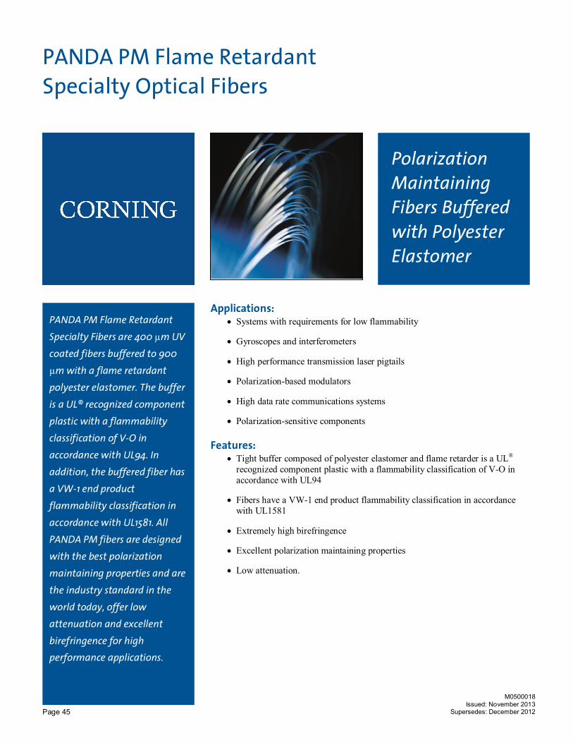
PANDA PM Flame Retardant Specialty Optical Fibers
PANDA PM Flame Retardant
Specialty Fibers are 400 µm UV
coated fibers buffered to 900
µm with a flame retardant
polyester elastomer. The buffer
is a UL® recognized component
plastic with a flammability
classification of V-O in
accordance with UL94. In
addition, the buffered fiber has
a VW-1 end product
flammability classification in
accordance with UL1581. All
PANDA PM fibers are designed
with the best polarization
maintaining properties and are
the industry standard in the
world today, offer low
attenuation and excellent
birefringence for high performance applications.
M0500018 Issued: November 2013
Supersedes: December 2012
Polarization Maintaining Fibers Buffered with Polyester Elastomer
Applications: · Systems with requirements for low flammability
· Gyroscopes and interferometers
· High performance transmission laser pigtails
· Polarization-based modulators
· High data rate communications systems
· Polarization-sensitive components
Features: · Tight buffer composed of polyester elastomer and flame retarder is a UL®
recognized component plastic with a flammability classification of V-O in accordance with UL94
· Fibers have a VW-1 end product flammability classification in accordance with UL1581
· Extremely high birefringence
· Excellent polarization maintaining properties
· Low attenuation.

Page 46
PM 1550 PM14XX PM 1300 PM 980 PM 850 PM 630 PM 480 PM 400 Key Optical Specifications Wavelength (nm) 1550 1400-1490 1300 980 850 630 480 410
Mode-field Diameter (µm) 10.5 ± 0.5 9.8 ± 0.5 9.0 ± 0.5 6.6 ± 0.5 5.5 ± 0.5 4.5 ± 0.5 4.0 ± 0.5 3.5 ± 0.5
Beat Length Range (mm) 3.0-5.0 2.8-4.7 2.5-4.0 1.5-2.7 1.0-2.0 ≤ 2.0 ≤ 2.0 ≤ 1.7 Maximum Cross Talk at 100 m (dB) -30 -30 -30 -30 -30 -30 -30 -30* Typical Cross Talk at 4 m (dB) -40 -40 -40 -40 -40 -40 -40 -40 Cutoff Wavelength (nm) 1300-1440 1260-1380 1130-1270 870-950 650-800 520-620 400-470 330-400 Maximum Attenuation (dB/km) 0.5 1.0 1.0 2.5 3.0 12 30 ≤ 50
Key Geometric, Mechanical and Environmental Specifications (-H90D) UV Polyester-Elastomer Part Number PM 15-H90D PM14- H 90D PM 13- H 90D PM 98- H 90D PM 85- H 90D PM 63- H 90D PM 48- H 90D PM 40- H 90D
Core-to-Cladding Offset (µm) ≤ 0.5 Coating Outer Diameter (µm) 900 ± 100 Cladding Outer Diameter (µm) 125 ± 1 Standard Lengths* 100 m, 200 m, 300 m, 400 m, 500 m, 1 km Proof Test (kpsi) 100 or 200 Operating Temperature (°C) -40 to 85
* For longer lengths contact Corning
Typical Cross-sectional View of PANDA PM Specialty Optical Fiber
PANDA PM Specialty Optical Fiber design uses two stress applying parts to create an extremely high birefringence, resulting in fiber with excellent polarization maintaining properties. This design was invented and patented by Corning Incorporated. Corning continues to have a manufacturing partnership with Fujikura Ltd.
For more information about Corning’s leadership in Specialty Fiber technology visit our website at www.corning.com/specialtyfiber
To obtain additional technical information, an engineering sample or to place an order for this product, please contact us at: Corning Incorporated Tel: +1-607-974-9974 © 2012 Corning Incorporated Fax: +1-607-974-4122 E-mail: [email protected]
M0500018 Issued: November 2013
Supersedes: December 2012

Page 47
PANDA PM High NA Specialty Optical Fibers
Designed for demanding
applications including fiber
optic gyroscopes, probes,
sensors and miniaturized
components, PANDA PM
high numerical aperture
(NA) fibers deliver extremely
high birefringence, low
insertion loss and excellent dimensional uniformity.
M0500020 Issued: November 2013
Supersedes: December 2012
High Numerical Aperture Polarization Maintaining Fibers
Applications: · Fiber optic gyroscopes
· Sensors
· Probes / Instrumentation
· Miniaturized components
· Polarization sensitive components
Features: · High numerical aperture
· Extremely high birefringence
· 80 µm cladding for 850 nm fiber
· Single-mode design
· Dual-layer UV acrylate coating
· Proof test available in 100 kpsi or 200 kpsi
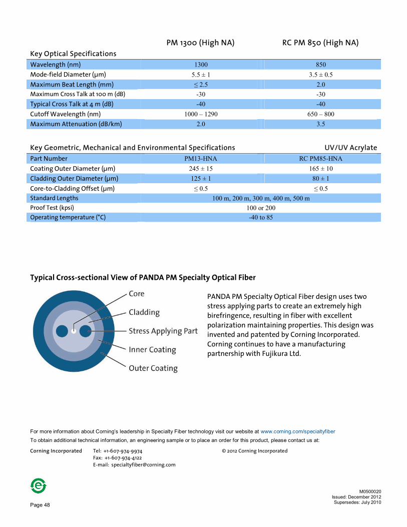
Page 48
PM 1300 (High NA) RC PM 850 (High NA) Key Optical Specifications Wavelength (nm) 1300 850 Mode-field Diameter (µm) 5.5 ± 1 3.5 ± 0.5 Maximum Beat Length (mm) ≤ 2.5 2.0 Maximum Cross Talk at 100 m (dB) -30 -30 Typical Cross Talk at 4 m (dB) -40 -40 Cutoff Wavelength (nm) 1000 – 1290 650 – 800 Maximum Attenuation (dB/km) 2.0 3.5
Key Geometric, Mechanical and Environmental Specifications UV/UV Acrylate Part Number PM13-HNA RC PM85-HNA Coating Outer Diameter (µm) 245 ± 15 165 ± 10 Cladding Outer Diameter (µm) 125 ± 1 80 ± 1 Core-to-Cladding Offset (µm) ≤ 0.5 ≤ 0.5 Standard Lengths 100 m, 200 m, 300 m, 400 m, 500 m Proof Test (kpsi) 100 or 200 Operating temperature (°C) -40 to 85
Typical Cross-sectional View of PANDA PM Specialty Optical Fiber
PANDA PM Specialty Optical Fiber design uses two stress applying parts to create an extremely high birefringence, resulting in fiber with excellent polarization maintaining properties. This design was invented and patented by Corning Incorporated. Corning continues to have a manufacturing partnership with Fujikura Ltd.
For more information about Corning’s leadership in Specialty Fiber technology visit our website at www.corning.com/specialtyfiber
To obtain additional technical information, an engineering sample or to place an order for this product, please contact us at: Corning Incorporated Tel: +1-607-974-9974 © 2012 Corning Incorporated Fax: +1-607-974-4122 E-mail: [email protected]
M0500020 Issued: December 2012 Supersedes: July 2010

Page 49
PANDA PM Bend Insensitive Specialty Optical Fibers
PANDA PM Bend Insensitive
Specialty Optical Fiber is
designed with significantly
improved bending capacity,
suited to meet the needs of
package size reductions and
100 Gbps systems.
PANDA PM fibers are
optimized for high reliability,
and our Boron-doped stress
rod profile is field proven to
support high growth
applications over a wide
temperature range.
M0500021 Issued: November 2013
Supersedes: December 2012
Polarization Maintaining Fibers for Bend Sensitive Applications
Applications: · Small package size transponders, transceivers, modulators and laser
fiber assemblies
· Sensors
· Bend sensitive applications
· Miniaturized components
· Polarization sensitive components
Features: · Significantly improved bending capacity
· Extremely high birefringence
· Single-mode design
· Fibers available with dual-layer UV acrylate and flame retardant polyester coatings

Page 50
PM 1550 (Bend Insensitive)
Key Optical Specifications For all coatings Wavelength (nm) 1550 Mode-field Diameter (µm) 9.5 ± 0.4 Maximum Beat Length (mm) 2.0 – 5.0 Maximum Cross Talk at 100 m (dB) -30 Maximum Bending Cross Talk (dB) (30 mm O.D; 1550 nm, 10 turns)
-30
Cutoff Wavelength (nm) ≤ 1440 Maximum Attenuation (dB/km) 0.50 Maximum Bending Loss (dB) (30 mm O.D; 1550 nm, 10 turns)
0.50
Key Geometric, Mechanical and Environmental Specifications Coating Type UV/UV Acrylate UV Acrylate/Polyester-Elastomer Part Number PMSR15-U40D-H PMSR15-H90D-H Core-to-Cladding Offset ≤ 0.5 ≤ 0.5 Coating Outer Diameter (µm) 400 ± 15 900 ± 100 Cladding Outer Diameter (µm) 125 ± 1 125 ± 1 Operating temperature (°C) -40 to 85 Standard Lengths 100 m, 200 m, 300 m, 400 m, 500 m Proof Test (kpsi) 200
Typical Cross-sectional View of PANDA PM Specialty Optical Fiber
PANDA PM Specialty Optical Fiber design uses two stress applying parts to create an extremely high birefringence, resulting in fiber with excellent polarization maintaining properties. This design was invented and patented by Corning Incorporated. Corning continues to have a manufacturing partnership with Fujikura Ltd.
For more information about Corning’s leadership in Specialty Fiber technology visit our website at www.corning.com/specialtyfiber
To obtain additional technical information, an engineering sample or to place an order for this product, please contact us at: Corning Incorporated Tel: +1-607-974-9974 © 2012 Corning Incorporated Fax: +1-607-974-4122 E-mail: [email protected]
M0500021
Issued: November 2013 Supersedes: December 2012

Page 51
Polarized fiber optimized for RGB wavelength band
RGB PM Specialty Optical Fiber Polarization Maintaining (PM) Fiber
The newly designed Panda RGB PM Specialty Optical Fiber is a polarization
maintaining fiber optimized for operation over the entire visible
spectrum. This increased wavelength range enables greater flexibility by
allowing for the use of a single fiber in applications across this region.
Applications:
n Medical
n Spectroscopy
n Display
Features:
n Designed for use at wavelengths between 405 nm and 630 nm
n Extremely high birefringence
n Excellent polarization maintaining properties
M0500040 Issued: December 2012 Supersedes: July 2012

Page 52
RGB PM Key Optical Specifications
Operating Wavelength (nm) 405-640 Cutoff Wavelength (nm) ≤ 400 Maximum Attenuation (dB/km) ≤ 50 @ 405 nm Mode-field Diameter (µm) 2.3 ± 0.6 @ 410 nm
3.8 ± 1.0 @ 630 nm Beat Length (mm) < 2.0 @ 630 nm Polarization Crosstalk @ 60mm bend diameter dB (dB/10 turn) -30 @ 630 nm
Key Geometric, Mechanical and Environmental Specifications
Cladding Outside Diameter (µm) 125 ± 1.0 Coating Outside Diameter (µm) 245 ± 15 Core-to-Cladding Offset (µm) 1.0 Proof Test (kpsi) 200 Operating Temperature* (°C) -40 to 85 Coating UV Curable Acrylate Recommended Minimum Bending Radius (mm) 30** * without coiling on a shipping reel ** set due to crosstalk performance
PANDA PM Specialty Optical Fiber design uses two stress applying parts to create an extremely high birefringence, resulting in fiber with excellent polarization maintaining properties. This design was invented and patented by Corning Incorporated. Corning continues to have a manufacturing partnership with Fujikura Ltd.
For more information about Corning’s leadership in Specialty Fiber technology visit our website at www.corning.com/specialtyfiber
To obtain additional technical information, an engineering sample or to place an order for this product, please contact us at: Corning Incorporated t + 1-607-974-9974 © 2012 Corning Incorporated f +1-607-974-4122 [email protected]
M0500040 Issued: December 2012 Supersedes: July 2012