Embed Size (px)
Citation preview

Cornell Rocketry TeamCritical Design Review
CORNELL ROCKETRY TEAM (CRT)CDR PRESENTATION

Cornell Rocketry TeamCritical Design Review
AIRFRAME

Cornell Rocketry TeamCritical Design Review
LAUNCH VEHICLE DIMENSIONS
Total Length 103”
Airframe Tubing OD = 5.15” ID = 5.00”
Coupler OD = 4.998” ID = 4.815”
Motor Mount Tube OD = 3.098” ID = 3.000”
Fin/Bulkhead Thickness = 3/32” Centering Ring Thickness = 1/8”
1515 Delrin Rail Buttons
Cornell Rocketry TeamCritical Design Review
LAUNCH VEHICLE COMPONENTS

Cornell Rocketry TeamCritical Design Review
MOTOR SELECTION
75mm AeroTech L1520T
Provides sufficient thrust to reach target apogee.
Maximum G-forces experienced by LV low enough that DRS will remain secured and undamaged during takeoff

Cornell Rocketry TeamCritical Design Review
STABILITY
From tip of nose cone
Center of Gravity (CG) = 59.34”
Center of Pressure (CP) = 78.29”
Static Stability Margin = 78.29" − 59.34"
5.15"= 3.68 cal

Cornell Rocketry TeamCritical Design Review
Total mass = 37.3 lb
Thrust-to-weight-ratio = 9.1
Projected apogee = 5478 ft
Velocity off rod = 81.4 ft/s

Cornell Rocketry TeamCritical Design Review
MASS STATEMENT
Mass Margin
Maximum mass before projected apogee below 5,000 ft: 40.3
Percent difference: 8%
Section Mass (lb)
Booster (launch mass/spent motor) 22.5 18.6
Forward 14.8
Total (launch mass/spent motor) 37.3 33.4

Cornell Rocketry TeamCritical Design Review
RECOVERY SYSTEM
Event Description Location Redundancy
1 Launch ready Launch pad N/A
2 Nose cone ejection Apogee 4000 ft
3 Booster section separation Apogee +0.5s Apogee +1.5s
4 Booster & AV separation Apogee +1s 4000 ft
5 All main parachutes deploy 500 ft N/A
6 Landing Ground level N/A

Cornell Rocketry TeamCritical Design Review
RECOVERY SYSTEM

Cornell Rocketry TeamCritical Design Review
RECOVERY SYSTEM
Forward and booster sections will use ½” thick, 25’ long kevlar shock cords
Launch Vehicle Component Drogue Size (in) Main Size (in)
Forward Section 15 72
Booster Section 18 96
Launch Vehicle Component
Drogue Descent Velocity (ft/s)
Drogue Kinetic Energy (ft-lb)
Main Descent Velocity (ft/s)
Landing Kinetic Energy (ft-lb)
Forward Section 82.19 1553.77 16.76 64.63
Booster Section 76.74 1700.56 14.14 57.76

Cornell Rocketry TeamCritical Design Review
RECOVERY SYSTEM DRIFT DISTANCES
Launch Vehicle Component
0 mph wind 5 mph wind 10 mph wind 15 mph wind 20 mph wind
Forward Section 0 645.18 1290.36 1935.55 2580.73
Booster Section 0 715.99 1431.97 2147.96 2863.95

Cornell Rocketry TeamCritical Design Review
SUBSCALE RESULTS
Apogee: 3110 ft
Projected apogee: 3128 ft
1% difference from measured apogee
Coefficient of drag: 0.58

Cornell Rocketry TeamCritical Design Review
SUBSCALE GROUND TESTING

Cornell Rocketry TeamCritical Design Review
SUBSCALE RECOVERY

Cornell Rocketry TeamCritical Design Review
AIRFRAME PLANNED TESTS
Full-Scale Ground Test
Test ObjectiveValidate that the black powder charges are sufficient to break the shear pins and separate the sections and verify that the recovery system properly deploys parachutes.
Success Criteria All Launch Vehicle sections separate cleanly, and all parachutes deploy.
Testing Variable Functionality of the recovery system.
MethodologyThe ejection charges are loaded into the AV bay and the forward airframe sections. All sections are assembled and secured with shear pins or rivets. Each charge is ignited manually to observe separations.

Cornell Rocketry TeamCritical Design Review
AIRFRAME PLANNED TESTS
Full-Scale Launch
Test Objective Validate the overall Launch Vehicle, payload, and recovery designs.
Success CriteriaAll recovery systems function as designed, the vehicle is stable during launch, and the vehicle is fully recoverable.
Testing Variable Functionality of the Launch Vehicle as a whole and the Launch Vehicle apogee.
Methodology
The Launch Vehicle is constructed following the design planned in the CDR documentation. The sections are assembled and attached using shear pins and rivets. The Launch Vehicle is launched using an AeroTech L1520T motor. The performance of the recovery system, recorded apogee, and any unanticipated launch events are analyzed for future full-scale launches.

Cornell Rocketry TeamCritical Design Review
COMMUNICATIONS (COMMS)

Cornell Rocketry TeamCritical Design Review
SYSTEM REQUIREMENTS
Required Features:
Use GPS and radio modules to determine the position of the Launch Vehicle at all points during the flight
Incorporate multiple GPS/radio transmitters onboard the Launch Vehicle
Determine the location of all sections of the Launch Vehicle after they have landed using the SRB, Homemade GRB, and TRACER module
Utilize multiple backup systems in the case that any single system fails to perform as expected
Additional Expectations:
Obtain video of flight utilizing an on-board camera
Onboard camera is the Xiaomi Yi, controlled by a Arduino Pro Mini
Save and transmit all flight information for vehicle tracking, post-launch analysis, and redundancy
Utilize and Arduino Mega to read data from every sensor on the TRACER shield and write to SD module

Cornell Rocketry TeamCritical Design Review
ELECTRICAL COMPONENTS

Cornell Rocketry TeamCritical Design Review
HOMEMADE GPS RADIO BEACON (PRIMARY SYSTEM)
Cornell Rocketry TeamCritical Design Review
HOMEMADE GPS RADIO BEACON (PRIMARY SYSTEM)
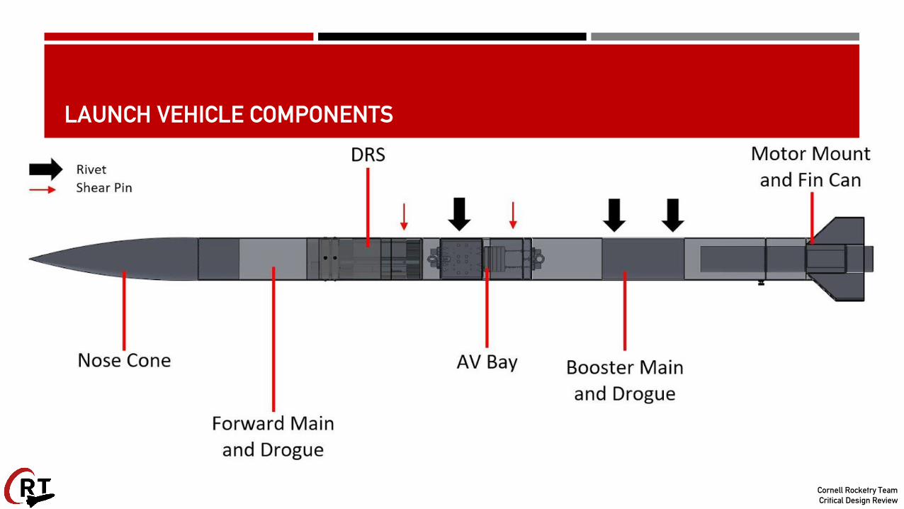
GPS Radio beacon
Onboard GPS module to gather positional information
Utilizes LoRa radio for transmission, which will allow for direct communication with Ground Station
Run by ATMEGA328P microprocessor
Custom firmware allows for fine control over information transmitted as well as interval of transmission and frequency of transmission
Cornell Rocketry TeamCritical Design Review
TRACER MODULE ELECTRONICS (PRIMARY SYSTEM)
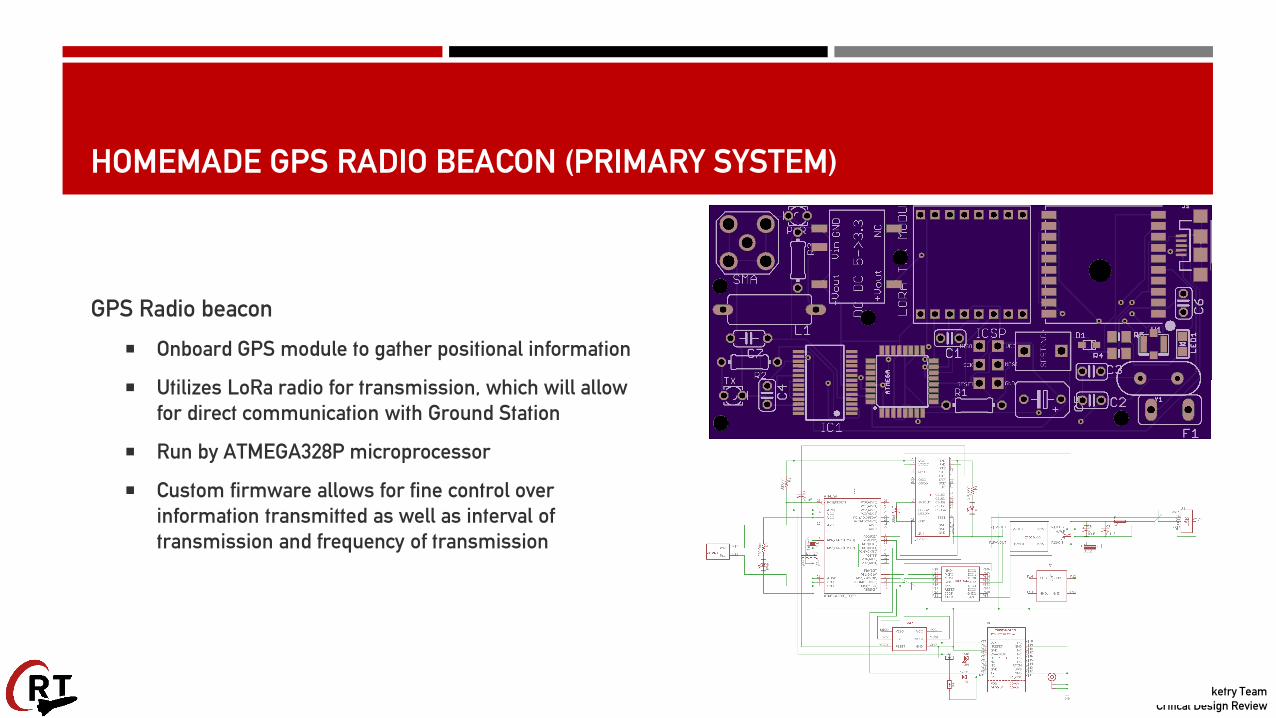
The TRACER Module Utilizes Arduino Mega connected to:
▪ GPS Module
▪ Adafruit 10DOF Sensor
▪ Xiaomi Yi
▪ SD Card Module
▪ LoRa Radio
Transmits data to Ground Station
Saves data to SD Card module
Xiaomi Yi assembly Includes Pro Mini to control camera state
Seated with lens facing out of nosecone to record flight

Cornell Rocketry TeamCritical Design Review
SIMPLE RADIO BEACON (REDUNDANT SYSTEM)
Simple Radio Beacon
Morse Transmission of HAM Radio Licensed Operator
Requires minimal power
Utilized for simple direction finding using fox-hunting techniques
Transmits at 100mW
Transmission occurs at a set interval of 10 seconds
Transmission contains no encoded information (only tone)
Cornell Rocketry TeamCritical Design Review
GROUND STATION GUI
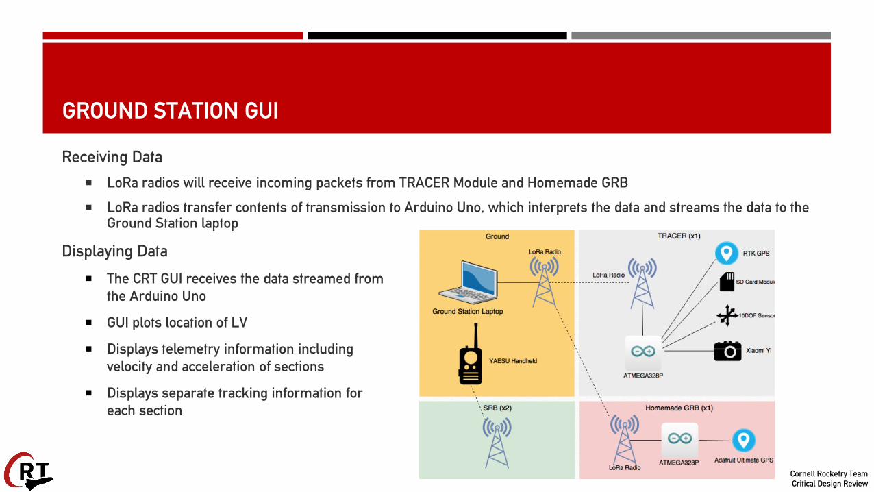
Receiving Data
LoRa radios will receive incoming packets from TRACER Module and Homemade GRB
LoRa radios transfer contents of transmission to Arduino Uno, which interprets the data and streams the data to the Ground Station laptop
Displaying Data
The CRT GUI receives the data streamed from the Arduino Uno
GUI plots location of LV
Displays telemetry information including velocity and acceleration of sections
Displays separate tracking information for each section

Cornell Rocketry TeamCritical Design Review
DEPLOYABLE ROVER SYSTEM (DRS)

Cornell Rocketry TeamCritical Design Review
DRS OVERVIEW
Two-wheeled rover
Lead Screw Mechanism (LSM) for deployment

Cornell Rocketry TeamCritical Design Review
ROVER
Two primary wheels
6.50” x 3.82” x 2.48” chassis
Stabilizing wheel
Solar panel housing

Cornell Rocketry TeamCritical Design Review
PRIMARY WHEELS
Premade rubber tire with deep treads
Premade wheel shell with grooves for the tire
3D-printed wheel insert and cap to contain nut, collar, and axle

Cornell Rocketry TeamCritical Design Review
AXLES AND MOTORS
Hex axle for stronger connections
Gear system to protect servo motor
Bearing to reduce friction
Collars for axial constraint

Cornell Rocketry TeamCritical Design Review
CHASSIS
Aluminum panel shell for strength
3D-printed body to house electronics
Rubber sealant for waterproofing
Cornell Rocketry TeamCritical Design Review
CHASSIS SHELL
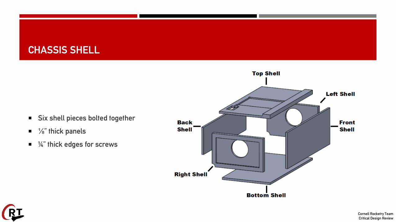
Six shell pieces bolted together
⅛” thick panels
¼” thick edges for screws
Cornell Rocketry TeamCritical Design Review
CHASSIS BODY
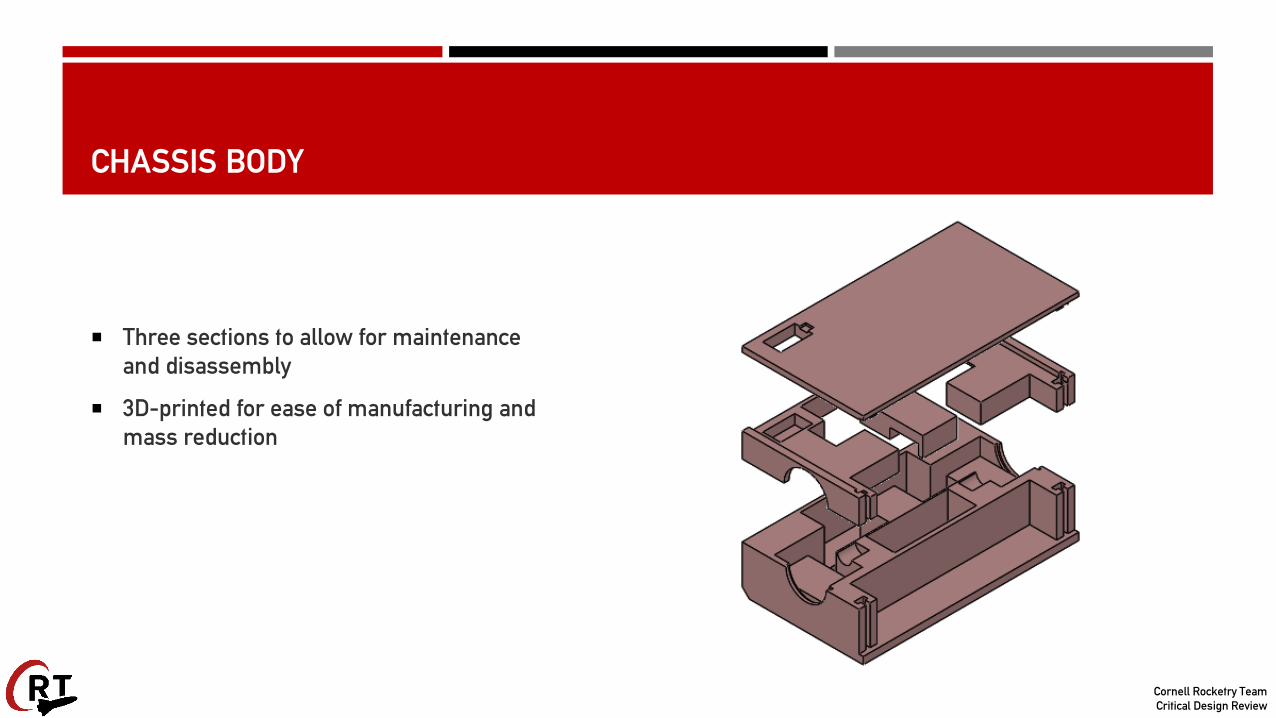
Three sections to allow for maintenance and disassembly
3D-printed for ease of manufacturing and mass reduction

Cornell Rocketry TeamCritical Design Review
CHASSIS BODY
Securely houses axles, electronics, and wiring

Cornell Rocketry TeamCritical Design Review
STABILIZING WHEEL
Prevents chassis from spinning in place
Folds under rover when stored, deployed by a spring-loaded hinge

Cornell Rocketry TeamCritical Design Review
SOLAR PANEL ACTUATION
Solar panels held with faces touching
Unfolded with a servo motor after rover stops

Cornell Rocketry TeamCritical Design Review
BOTTOM SOLAR PANEL HOUSING
Bottom solar panel held face up on the top shell of the chassis
Rectangular hole with protrusions to allow for sharp angles

Cornell Rocketry TeamCritical Design Review
TOP SOLAR PANEL HOUSING
3D printed slot connected to the servo motor

Cornell Rocketry TeamCritical Design Review
LEAD SCREW MECHANISM (LSM)
Deploys rover by turning lead screw
Secured via mounting screws
Guide shafts removed due to overconstraint

Cornell Rocketry TeamCritical Design Review
MOTOR COMPLIANCE ASSEMBLY (MCA)
Square nuts prevent nuts from spinning in place
Forward bulkhead moves in plane to prevent load on lead screw

Cornell Rocketry TeamCritical Design Review
MOTOR COMPLIANCE ASSEMBLY (MCA)
Ball bearings to reduce friction for the forward bulkhead
Lead screw coupled to DC motor
Coupling constrained by aft bulkhead

Cornell Rocketry TeamCritical Design Review
SLEDS
Sit between the wheels
Constrained by tire treads
Ball bearings to reduce friction
Fall off after rover is deployed

Cornell Rocketry TeamCritical Design Review
AIRFRAME INTEGRATION
Aft end shear pinned to AV forward airframe
Forward end attached to forward airframe using mounting screws
Bulkhead cap tethered to AV Bay

Cornell Rocketry TeamCritical Design Review
SUBSCALE PROTOTYPE
Former design using fixed LSM, guide shafts and moving bulkheads
Chassis and wheels both entirely 3D-printed

Cornell Rocketry TeamCritical Design Review
SUBSCALE PROTOTYPE
Added tether to prevent personnel hazard
Unable to deploy due to overconstraint

Cornell Rocketry TeamCritical Design Review
DRS TESTING - MECHANICAL
Centrifuge Test
Impact Test
Splash Test
Solar Panel Deployment Test
Drawbar Pull Test
Ground Terrain Test
Slope Test
Reorientation Test

Cornell Rocketry TeamCritical Design Review
ELECTRICAL & SOFTWARE (E&S)
Cornell Rocketry TeamCritical Design Review
POWER
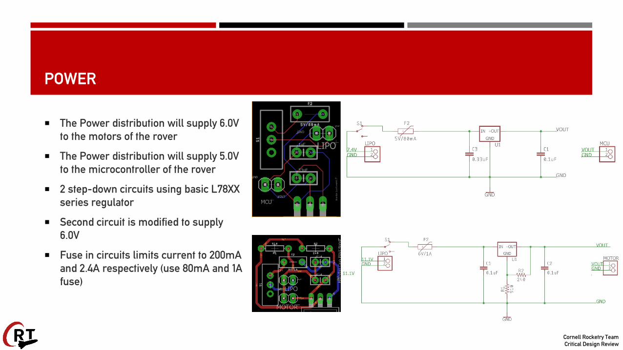
The Power distribution will supply 6.0V to the motors of the rover
The Power distribution will supply 5.0V to the microcontroller of the rover
2 step-down circuits using basic L78XX series regulator
Second circuit is modified to supply 6.0V
Fuse in circuits limits current to 200mA and 2.4A respectively (use 80mA and 1A fuse)

Cornell Rocketry TeamCritical Design Review
MOTORS
Pololu 99:1 25Dx54L DC motor for linear actuator
▪ Updated from subscale (increased RPM, adjusted torque requirements)
▪ 97 RPM
▪ 13.13 lb-in stall torque (2.2 min required)
Power supply of 6.0V
Schematic includes flyback diodes to prevent current spikes, decoupling capacitors to reduce noise
Board has wider trace widths to avoid burnout in the connections

Cornell Rocketry TeamCritical Design Review
MOTORS
Two Pololu Power HD Continuous Rotation servos for wheel motors
Also updated from subscale
71 RPM
5.8 lb-in stall torque (1.5 min required)
Power supply of 6.0V
Similar decoupling capacitors and flyback diodes used
Trace widths increased as well

Cornell Rocketry TeamCritical Design Review
WIRELESS COMMUNICATION
Requirements:
Must be able to transmit at least one mile.
Must be able to accurately transmit data at distance
Modules:
Both Ground and LV use Xbee Pro 900
Ground module uses elevated Yagi Antenna
LV module uses a half dipole antenna

Cornell Rocketry TeamCritical Design Review
WIRELESS COMMUNICATIONS LOGIC
Uses two step authentication:
▪ Initial packet
▪ Trigger Packet

Cornell Rocketry TeamCritical Design Review
CONTROLS (LSM)
LSM is controlled using ATMega328p
Operates at 5.0V and 16MHz
FTDI chip used for fast programming and debugging
RFM69 Wireless Transceiver used for communication between LSM and rover Controls modules
Level shifting is required for communication between the ATMega and the transceiver
Integrates with LSM motor controller and Wireless Communication system
Will run LSM for predetermined amount of time to ensure that the rover is out of the LV, then transmits a “go” packet to the rover Controls module

Cornell Rocketry TeamCritical Design Review
CONTROLS (LSM)

Cornell Rocketry TeamCritical Design Review
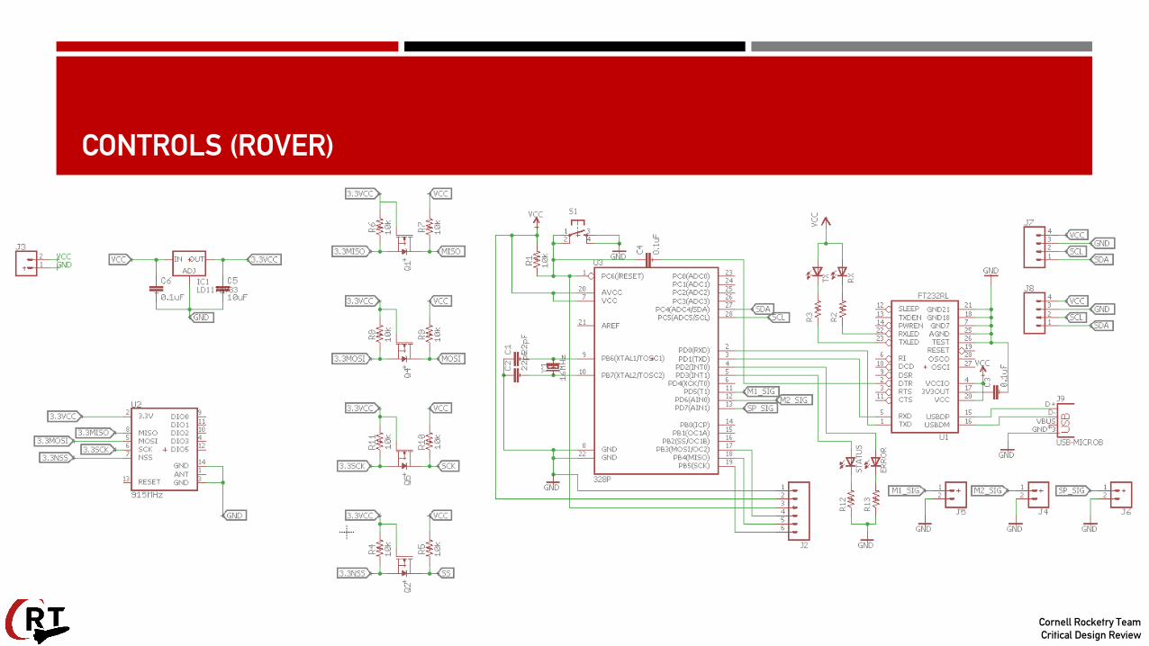
CONTROLS (ROVER)
Rover uses ATMega328p as onboard computer
Operates at 5.0V and 16MHz
Includes RFM69 Transceiver
To receive signal for rover activation
Same level shifter setup as LSM Controls module
Uses same FTDI programming interfaces as LSM Controls module
Has interfaces with PWM pins for communicating with the rover’s servos
Has I2C interface to receive distance information from time of flight distance sensors
Upon receiving “go” signal from LSM, will begin navigation algorithm and attempt to travel 5 ft from the LV
Cornell Rocketry TeamCritical Design Review
CONTROLS (ROVER)

Cornell Rocketry TeamCritical Design Review
OBJECT AVOIDANCE
Two Time of Flight Distance Sensors
Mounted to front of chassis
I2C Communication
Rover remains idle until signal is received from LSM
System runs through state machine until timer ends

Cornell Rocketry TeamCritical Design Review
SOLAR PANELS
Must be able to expand in area size
Foldable model using 2 panels
Cannot exceed output of 5.0V
Required to protect microcontroller
Open Circuit Voltage of 4.9V
Voltage information shown on 7-pin display
Must be able to fit within chassis area (2.3” x 1.9”)

Cornell Rocketry TeamCritical Design Review
TESTING
DRS Rover Sensor Test
DRS Rover Ground Test
DRS Wheel Motor Torque Test
Accuracy of Wireless Communications Test
Wireless Communications Range Test

Cornell Rocketry TeamCritical Design Review
INDEPENDENT TEST AND VALIDATION (INTEV)

Cornell Rocketry TeamCritical Design Review
INTEV MISSION REQUIREMENTS
All components on board the LV shall be capable of completing the mission
Appropriate testing procedures shall be developed to produce valuable data through reliable and repeatable testing of components
Long-term, general-use testing devices shall be built to validate models and predictions

Cornell Rocketry TeamCritical Design Review
PLANNED TESTING
General Testing
Centrifuge: Verifies onboard components can withstand up to and including 8 g’s of constant acceleration (launch acceleration load expected from motor curve)
Shock Test Rig (STR): Verifies onboard components can withstand up to 75 g’s of impulse acceleration
Subsystem Specific Testing
Motor Test Rig (MTR): Characterizes actual motor torque/RPM, allows verification of expected specifications
Parachute Test Rig (PTR): Characterizes parachute drag force in various recovery configurations, allows verification of Launch Vehicle recovery system

Cornell Rocketry TeamCritical Design Review
REQUIREMENTS VERIFICATION – COMPLETED, SEPTEMBER
Section 2 (Launch Vehicle)
The Launch Vehicle will be designed to be recoverable and reusable. Reusable is defined as being able to launch again on the same day without repairs or modifications
The Launch Vehicle will have a maximum of four independent sections
The Launch Vehicle will be limited to a single stage
Section 4 (Payload)
Each team will choose one design experiment option from the following list
Section 5 (Safety)
Each team must identify a student safety officer who will be responsible for all items in section 5.3
During test flights, teams will abide by the rules and guidance of the local rocketry club’s RSO (ongoing)
Teams will abide by all rules set forth by the FAA (ongoing)

Cornell Rocketry TeamCritical Design Review
REQUIREMENTS VERIFICATION – COMPLETED, OCTOBER
Section 2 (Launch Vehicle)
All teams will successfully launch and recover a subscale model of their rocket prior to CDR
The subscale model should resemble and perform as similarly as possible to the full-scale model, however, the full-scale will not be used as the subscale model
The subscale model will carry an altimeter capable of reporting the model’s apogee altitude
The Launch Vehicle will not utilize forward canards
The Launch Vehicle will not utilize forward firing motors
The Launch Vehicle will not utilize motors that expel titanium sponges (Sparky, Skidmark, MetalStorm, etc.)
The Launch Vehicle will not utilize hybrid motors
The Launch Vehicle will not utilize a cluster of motors
The Launch Vehicle will not utilize friction fitting for motors

Cornell Rocketry TeamCritical Design Review
REQUIREMENTS VERIFICATION – COMPLETED, NOVEMBER
Section 3 (Recovery System)
The recovery system electrical circuits will be completely independent of any payload electrical circuits.
All recovery electronics will be powered by commercially available batteries
The recovery system will contain redundant, commercially available altimeters
Removable shear pins will be used for both the main parachute compartment and the drogue parachute compartment
An electronic tracking device will be installed in the Launch Vehicle and will transmit the position of the tethered vehicle or any independent section to a ground receiver
Any rocket section, or payload component, which lands untethered to the Launch Vehicle, will also carry an active electronic tracking device
Section 4 (Payload)
Teams will design a custom rover that will deploy from the internal structure of the Launch Vehicle

Cornell Rocketry TeamCritical Design Review
REQUIREMENTS VERIFICATION – JANUARY
Section 2 (Launch Vehicle)
Each altimeter will be armed by a dedicated arming switch that is accessible from the exterior of the rocket airframe when the rocket is in the launch configuration on the launch pad
Each altimeter will have a dedicated power supply
Each arming switch will be capable of being locked in the ON position for launch (i.e. cannot be disarmed due to flight forces)
The Launch Vehicle will be capable of being launched by a standard 12-volt direct current firing system. The firing system will be provided by the NASA-designated Range Services Provider
The Launch Vehicle will require no external circuitry or special ground support equipment to initiate launch (other than what is provided by Range Services)
The Launch Vehicle will use a commercially available solid motor propulsion system using ammonium perchlorate composite propellant (APCP) which is approved and certified by the National Association of Rocketry (NAR), Tripoli Rocketry Association (TRA), and/or the Canadian Association of Rocketry (CAR)

Cornell Rocketry TeamCritical Design Review
REQUIREMENTS VERIFICATION – JANUARY
Section 2 (Launch Vehicle, continued)
The total impulse provided by a College and/or University Launch Vehicle will not exceed 5,120 Newton-seconds (L-class)
Any structural protuberance on the rocket will be located aft of the burnout center of gravity
Section 3 (Recovery System)
The recovery system altimeters will be physically located in a separate compartment within the vehicle from any other radio frequency transmitting device and/or magnetic wave producing device
The recovery system electronics will be shielded from all onboard transmitting devices, to avoid inadvertent excitation of the recovery system electronics
The recovery system electronics will be shielded from all onboard devices which may generate magnetic waves (such as generators, solenoid valves, and Tesla coils) to avoid inadvertent excitation of the recovery system
The recovery system electronics will be shielded from any other onboard devices which may adversely affect the proper operation of the recovery system electronics
Cornell Rocketry TeamCritical Design Review
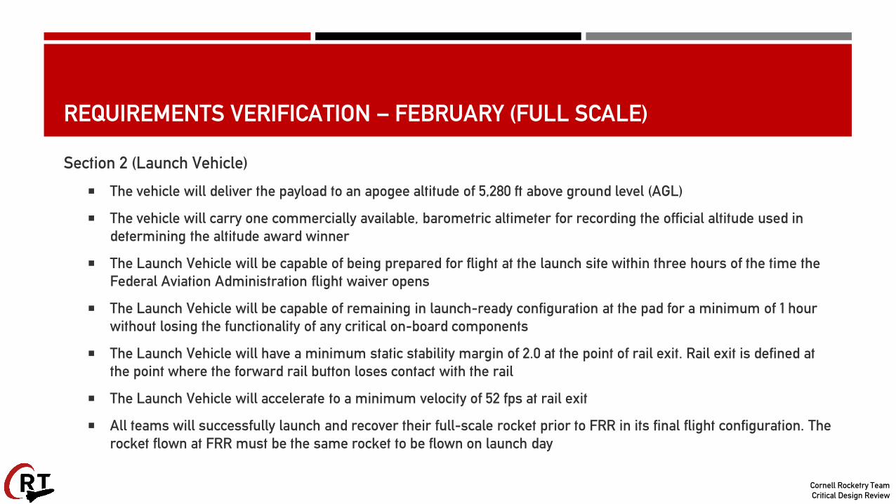
REQUIREMENTS VERIFICATION – FEBRUARY (FULL SCALE)
Section 2 (Launch Vehicle)
The vehicle will deliver the payload to an apogee altitude of 5,280 ft above ground level (AGL)
The vehicle will carry one commercially available, barometric altimeter for recording the official altitude used in determining the altitude award winner
The Launch Vehicle will be capable of being prepared for flight at the launch site within three hours of the time the Federal Aviation Administration flight waiver opens
The Launch Vehicle will be capable of remaining in launch-ready configuration at the pad for a minimum of 1 hour without losing the functionality of any critical on-board components
The Launch Vehicle will have a minimum static stability margin of 2.0 at the point of rail exit. Rail exit is defined at the point where the forward rail button loses contact with the rail
The Launch Vehicle will accelerate to a minimum velocity of 52 fps at rail exit
All teams will successfully launch and recover their full-scale rocket prior to FRR in its final flight configuration. The rocket flown at FRR must be the same rocket to be flown on launch day

Cornell Rocketry TeamCritical Design Review
REQUIREMENTS VERIFICATION – FEBRUARY (FULL SCALE)
Section 2 (Launch Vehicle, Continued) The vehicle and recovery system will have functioned as designed
If the payload changes the external surfaces of the rocket (such as with camera housings or external probes) or manages the total energy of the vehicle, those systems will be active during the full-scale demonstration flight
The full-scale motor does not have to be flown during the full-scale test flight. However, it is recommended that the full-scale motor be used to demonstrate full flight readiness and altitude verification. If the full-scale motor is not flown during the full-scale flight, it is desired that the motor simulates, as closely as possible, the predicted maximum velocity and maximum acceleration of the launch day flight
The vehicle must be flown in its fully ballasted configuration during the full-scale test flight. Fully ballasted refers to the same amount of ballast that will be flown during the launch day flight. Additional ballast may not be added without a re-flight of the full-scale Launch Vehicle
After successfully completing the full-scale demonstration flight, the Launch Vehicle or any of its components will not be modified without the concurrence of the NASA Range Safety Officer (RSO)
Full scale flights must be completed by the start of FRRs (March 6th, 2018)
The Launch Vehicle will not exceed Mach 1 at any point during flight
Vehicle ballast will not exceed 10% of the total weight of the rocket

Cornell Rocketry TeamCritical Design Review
REQUIREMENTS VERIFICATION – FEBRUARY (FULL SCALE)
Section 3 (Recovery System)
The Launch Vehicle will stage the deployment of its recovery devices, where a drogue parachute is deployed at apogee and a main parachute is deployed at a lower altitude
Each team must perform a successful ground ejection test for both the drogue and main parachutes. This must be done prior to the initial subscale and full-scale launches
At landing, each independent sections of the Launch Vehicle will have a maximum kinetic energy of 75 ft-lbf
Recovery area will be limited to a 2500 ft radius from the launch pads
The recovery system electronics will not be adversely affected by any other on-board electronic devices during flight (from launch until landing)
Section 4 (Payload)
At landing, the team will remotely activate a trigger to deploy the rover from the rocket
After deployment, the rover will autonomously move at least 5 ft. (in any direction) from the Launch Vehicle
Once the rover has reached its final destination, it will deploy a set of foldable solar cell panels

Cornell Rocketry TeamCritical Design Review
PROJECT PLAN

Cornell Rocketry TeamCritical Design Review
EDUCATIONAL ENGAGEMENT
Completed Events Event Date Grades 5-9 All Grades
Ithaca Math Circle #1 10/14/2017 2 15
Carl Sagan Walk 10/14/2017 11 17
Spooky Science Day 10/29/2017 72 80
Ithaca Math Circle #2 11/05/2017 4 17
Ithaca Math Circle #3 11/17/2017 1 10
Ithaca Math Circle #4 12/10/2017 0 12
Total 90 151
Cornell Rocketry TeamCritical Design Review
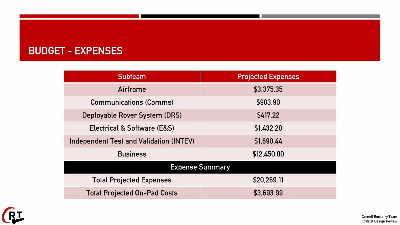
BUDGET - EXPENSES
Subteam Projected Expenses
Airframe $3,375.35
Communications (Comms) $903.90
Deployable Rover System (DRS) $417.22
Electrical & Software (E&S) $1,432.20
Independent Test and Validation (INTEV) $1,690.44
Business $12,450.00
Expense Summary
Total Projected Expenses $20,269.11
Total Projected On-Pad Costs $3,693.99

Cornell Rocketry TeamCritical Design Review
BUDGET - INCOME
Source of Funding Contribution
Cornell University Organizations $12,000.00
Corporations $5,250.00
Gifts in Kind $1,345.00
Fundraising $1,849.00
Budget Summary
Income $20,444.00
Expenses $20,269.11
Total Surplus/Deficit +$174.89