Embed Size (px)
Citation preview

CORN LIFTERSCORN LIFTERSCORN LIFTERSCORN LIFTERS
PICKUP ATTACHMENT FOR CORN HEADSPICKUP ATTACHMENT FOR CORN HEADSPICKUP ATTACHMENT FOR CORN HEADSPICKUP ATTACHMENT FOR CORN HEADS
IF YOU HAVE DOWN CORN IF YOU HAVE DOWN CORN IF YOU HAVE DOWN CORN IF YOU HAVE DOWN CORN ————----
WE HAVE THE MACHINE TO GET ITWE HAVE THE MACHINE TO GET ITWE HAVE THE MACHINE TO GET ITWE HAVE THE MACHINE TO GET IT
7655 ROLL-A-CONE RD TULIA, TX. 79088 806-668-4722

2
∗ Gently lifts and guides stalks as the corn
head moves under them.
∗ Simple installation.
∗ Can be adapted to any make or model corn
head.
∗ Drives either mechanically or with hydrau-
lic motor.
∗ Corn head snout retains its flexibility be-
cause cones have telescoping drive shafts.
∗ Eliminates necessity for operator to clear
any clog-ups by hand.
∗ Extremely light weight but built to give
good service over a lot of acres.
∗ Reel attachment keeps loose stalks fed into
machine eliminating stoppages.
SEE YOUR DEALER
or Call: ROLL-A-CONE MFG. CO.
806-668-4722

3
INSTALLATION INSTRUCTION
FOR CORN CONES
1. Assemble the bearings (C-1O) and flangettes (C-20) onto the shafts which extend from the
cones. The set collar side of the bearing goes on toward the upper (large) end of the cone. Tighten
the set collar with a punch, and then tighten the alien screw. Install the 7/8 washer and put the cotter
pin through the small hole in the end of the cone shaft. (See Fig # 1).
2. Using the stud bolts which extend down from the nose shield (C-21) as a template, mark your
snout as indicated. (See Fig #2) Drill an oversize 1/2” hole. Now you are ready to mount the nose
shields onto each cone by bolting the loose flanges above the bearing onto the flange half which is
welded on the nose shield.
3. Use the cone with nose shield mounted as a gauge now to locate the position in which you will
install the drive unit. The best way to do this is to hang the drive unit above the back of the header
using a hoist of some kind. With the drive unit hanging above the rear of the cone head, slip a cone
onto one of the drive shafts (C-7). NOTE: All shields which interfere with the mounting of the
drive unit must be removed, this is at your discretion. These drive shafts should be pointing toward
the tips of the snouts. Move the drive unit around until it is in approximately the position indicated
on the drawing (Fig # 3). This position is not critical, so don’t be afraid to change it around some if
necessary to make your drive line up better or to keep from getting into your windshield. The main
thing is that approximately 5” to 10” of the small drive shaft (C-7) should extend out of the cone so
that when the snout of your corn head flexes upward, the cone will have room to rise with it with-
out hitting the pulley. While positioning the drive unit, keep the top of the main bar (2” square tub-
ing) flat with the header in the down position. If you install this bar tilted severely one way or the
other, the belts will not feed onto the pulleys properly. NOTE: On some combines, particularly
Gleaners, there is very little room between the pulleys on the drive unit and the glass front of the
cab. Be careful that the drive unit is installed so that it won’t break the glass. Use the brackets
which came with the machine to attach the drive unit. In some cases you may have to modify the
mounting brackets to make them work on your corn head. See the loose supplement page pertaining
to your combine for more detailed mounting instructions.
4. With the drive unit installed as described above, you are now ready to slip each cone with nose
shield onto the drive shafts. The direction of the rotation of each drive shaft is predetermined at the
factory. You must match LEFT HAND CONES with counterclockwise turning drive shafts (Fig #
4). Turn the drive shaft with a pipe wrench the same directions that your auger turns to check rota-
tion of cone drive shafts, (C-7) (Direction of rotation is determined as if you are sitting in drivers
seat looking forward). If matched properly, each cones fighting will seem to move upward while
turning the line shaft. Now insert the two studs extending out of the nose shields into two holes
which you drilled into the corn head snouts earlier. Tighten the two nuts until the nose shield fits
firmly onto the top of the snout. If necessary use a hammer to make the nose shield conform as
closely as possible to the snout.
5. All pulleys must be adjusted so that the belts run straight and do not rub. (Fig # 5). Next, tighten
all the set collars on the bearings, tighten all allen screws on the set collars and tighten the set
screws on the pulley. Tighten belts slightly. (DO NOT OVERTIGIITEN).

4
7. There are two main ways to drive this machine, hydraulically and mechanically.
HYDRAULICALLY: Use the hydraulic motor off your grain head (or any hydraulic
motor which you may have.) The motor mounts onto the hydraulic motor bracket
(furnished). Install the drive sprocket (furnished) onto the motor. Using the # 50 chain
connect the drive sprocket to the line shaft sprocket. Tighten by sliding the entire
motor bracket back toward the back and tighten the 1/2” set screws (Fig # 7). Line
shaft will vary according to conditions, but 60-80 RPM (line shaft speed) is a good
starting point.
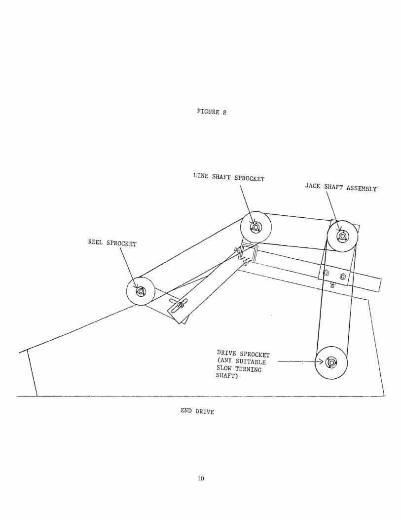
MECHANICALLY: Corn lifters can be driven mechanically on any combine, in most
cases there is a factory drive method worked out. However, due to the vast number of
variations of corn heads there may be rare cases where the drive sprockets furnished do
not fit. In these cases it is the customers responsibility to make the drive work on the
combine. To do this, a rule of thumb would be to find the slowest turning shaft on the
corn head. If possible, mount your drive sprocket to this shaft and drive up to the jack
shaft assembly. Any method of driving which is workable and is safe, is all right. The
recommended cone speed varies with the conditions you have, but approximately 80
RPM (at shaft speed) is a good point to start. See Fig # 8.
8. Use a file or sand paper to dress any nick or rough place off the flights, where they first
contact the corn stalk at the small end of the cones. Check and tighten all bolts, set
screws, bearing collars, and belts. Check the alignment of all the belts and drive chains.
Start the machine and let it turn slowly for a few minutes. Observe carefully for a few
minutes for any potential problems. If there are none, you are ready to take the
machine to the field. NOTE:there is an extra sprocket (32 tooth). This is a speed
change sprocket which can be used to either speed up or slow down the machine
depending on where it is mounted.
6. Mount the reel mounting brackets (R-3 & R-4) onto the main support bar (C-8) so that
the bearing supports are approximately equally spaced apart, and so that support on the
end which is driven is close enough to the sprocket and chain to support it properly.
Next slide the shaft for the reel through the bearings and through the bat assemblies
(R-5), which operate in the middle of the row. Adjust the mounting brackets so that
the bats are in the proper place (Fig # 6) and tighten all the bolts. Use the two sprockets
which are bolted to the hubs to get power from the main line shaft via a # 50 chain
down to the reel shaft. Use the idler arm with the wood block to take the slack out of
the loose side of the chain.

5
FLANGETTES
BEARING
FIGURE 1

6
Metal Snout August 2011
There are 2 nuts and washers on each of the nose shield bolts. The top nuts and washers go on top of
the snout. These are used to adjust the nose shield height. The bottom nuts and washers go under the
snout to clamp on the nose shield. Please see back of book for poly snouts.

7
FIGURE 4
RIGHT llANO CLOCKWI SE
LEFT HAND COUNTERCLOCKWISE
FIGU RE 5
B ~ .h
......,
~ i } @ ~

8
INSTRUCTIONS FOR REEL ATTACHMENT
Mount one reel attachment bracket as close as possible to drive sprocket. Space the
remaining three as evenly as possible. Center the beater brackets over each row. Alternate po-
sitions with the beater bracket on every other row. Adjust reel to where it works best for crop
conditions.

9
FIGURE 7
SIDE VIEW
TOP VIEW
HYDRAULIC HOTOR
r'""'" LINE SHAFT
/ 1
LI
BEARING MOTOR ~!OUNT - RrR
~ -
- PLAT~ :::::--:: NE SHAFT SPROCKET
~ I» tt IlII l P-
-W 1't5 '--1
1 u
r CHAIN REEL DRIVE SPr.:JCKET MOTOR SPROCKET
10
REEL SPROCKET
FIGURE 8
LINE SHAFT SPROCKET
END DRIVE
DRIVE SPROCKET (ANY SUITABLE SLOt< TURNING SHAFT)
JACK SHAFT ASSEHBLY
@

11
ASSEMBLY OF FRAME FOR CORN MACHINES
PLEASE READ ALL INSTRUCTIONS BEFORE STARTING
ASSEMBLY
Begin by marking off your centers on the main frame (2x2 tubing) starting from
the end opposite from which you will drive the machine. Three or four inches to
the first mark will be fine. This should leave room for the drive bracket (C-12)
and reel attachment brackets. See Figure B. On some machines it may be neces-
sary to bring in the two outside carrier brackets (C-4) in order to line the cones up
with the cornhead. After marking your frame off, go ahead and slide the carrier
brackets on and lock them down using the 1/2” set screws. Next bolt the bearing
brackets (C-5) onto the carrier brackets. These may be pre-assembled from the
factory. If not, use the 1/2x1-1/2” carriage bolts and nuts supplied. Be sure that
the bend faces away from the frame. Do not tighten these bolts until you have
completely finished assembly.
Lay the line shaft out with the keyed end on the same side as the access main
frame tubing. Slide all necessary pulleys, bearings, flangettes and locking collars
onto the line shaft. This has to be done correctly or the cones will not turn the
right direction. Each carrier bracket will have one drive pulley, one idler pulley,
one bearing with locking collar and two flangettes. When driving a right hand
cone the drive pulley will be mounted on the right hand side of the carrier
bracket. When driving a left hand cone the drive pulley will be mounted on the
left hand side. (See Figure B). Before you continue, lay one belt (C-6) over each
carrier bracket.
Now bolt the line shaft onto the carrier brackets using the 5/16x1” carriage bolts
and nuts supplied.
Take each drive shaft (C-7) and slide a drive pulley (C-1) onto it with the set
screws going on first. Next slide one flangette (C-20) on, one bearing (C-10),
one more flangette and the locking collar. The idler pulleys go on last. They
should be pre-assembled at the factory. Install cotter pins in the holes on the ends
of the shafts. DO NOT FORGET THIS.
Take the assembled drive shafts and bolt them onto the bearing brackets
(C-5) using two 5/16x1” bolts and nuts. Lay the belts over the pulleys as shown in
Figure C and align all pulleys. Do not tighten any set screws or locking collars
until the cones are mounted onto the cornhead. After everything is mounted, be
sure the belts are running straight, adjust the tension of the belts and lock down
the 1/2” carriage bolts and nuts. Check the drawings for the positioning of the
cones.

12
ROLL-A-CONE MFG. & DIST. CO., INC.
7655 ROLL-A-CONE RD.
TULIA TX 79088
PHONE: 806-668-4722 FAX: 806-668-4725
E:Mail: [email protected] Web Page: www.roll-a-cone.com
May 2008
C-1 Driver Pulley
C-2 Idler Pulley
C-3 Line Shaft (Per Foot)
C-4 Carrier Bracket
C-5 Bearing Bracket
C-6 Belt (BB-60)
C-7 Drive Shaft
C-8 Main Support (Per Foot)
[2x2 Square Tubing]
C-9-1 Bolt On Sprocket
C-9-2 Bolt On Hub
C-10 Bearing
C-12 Drive Bracket (Specify Right or Left)
C-13-1 Top Jack Shaft Bracket
C-13-2 Lower Bracket
C-14-22 22 Tooth Sprocket
C-14-24 24 Tooth Sprocket
C-14-26 26 Tooth Sprocket
C-15-32 32 Tooth Sprocket
C-16 Jack Shaft
C-17 Hydraulic Drive Sprocket
C-18 #50 Chain (Per Foot)
C-19 Cone (Specify Right or Left)
C-20 Flangettes
C-21 Shield (Metal)
C-21P Shield (Plastic)
C-23 Motor Mounting Bracket
C-24 Mechanical Drive Sprocket
C-26 Idler Arm
C-27 Wood Block
C-28 Spring
C-29 7/8” Line Shaft Connector
C-30 Flighting
C-32 2” Square to 2” Square Coupler
C-40 Needle Valve
C-41 Woodruff Key

13
—8
-32
3
-12
-30
-29
-1
-1
2-
2—
6
-14
-15
-9-1
-9-2
-17
chai
n
-18
-40
16
-21
20
--
10
-27
-26
28
-
-24
2
3-
20
-
-10
-5
-20
10
-2
0
4
-7
13
-1
13
-2

14
RIGHT AND LEFT HAND CONE PLACEMENT
CONES EVERY OTHER ROW
SKIP SKIP
8
ROW
6
ROW
4
ROW
RIGHT HAND
RIGHT HAND
RIGHT HAND
LEFT HAND
LEFT HAND
RIGHT HAND

15
SKIP SKIP
RIGHT HAND
RIGHT HAND
LEFT HAND
RIGHT HAND
LEFT HAND
LEFT HAND

16
SiUin in the :tb lookin forwlu'(l this will be the left hand side.
lei
4.ROW ( RIGI·ITHAi\'D LEFT HAND RIGHT HAND RIGHT H.-\,.'1D
6·ROW ( RIGHT HAND LEFT f-IAND RIGHT HAND LEEr HAND
g·ROW ( RIGHT HAj\'D LEFT HAND , RJGIfT HAND I.EfT HAND

17
RIGHT AND LEFT HAND CONE PLACEMENT
FIGURE A

18
RIGHT HAND CONE

19
SET CARRIER BRACKETS
ON CENTERS 30-38-40– etc.
Except on the outside rows. They should be
angled in 10 to 12 inches

20
FIGURE C

21

22
Mounting Bracket Parts MB-1 Cross Piece
MB-2 Straight Ext. Arm
MB-3 Bar Clamp
MB-3A Carrier Bracket
MB-4 Base
MB-5 Back Up Plate
MB-6 Extension
MB-7 90 Ext. Arm
MB-8 Stop Clamp
MB-9 Strap
MB-10-3 3” Z Clamp
MB-10-4 4” Z Clamp
MB-10-5 5” Z Clamp
Mounting Brackets MBJD John Deere
MBIHC International
MBGL Gleaner Adjust
MBGLH Gleaner Hugger
MBMA Massey
MBWH White
MBFORD Ford
MBNH New Holland
MBNI New Idea
MBCAT Caterpillar

23
Reel Attachment
R-1-1 Sprocket ........................................... 21.00
R-1-2 Bolt on Hub ...................................... 23.00
R-2 7/8” Line Shaft ................................... 4.00
R-3 Upper Mounting Bracket ................. 22.00
R-4 Lower Mounting Bracket ................. 20.00
R-5-1 Bat Bracket ....................................... 16.00
R-5-2 Bat Only ........................................... 10.00
R-6 Bearing ............................................. 14.00
R-7-1 Idler Arm ............................................ 5.00
R-7-2 Wood Block ....................................... 5.00
R-8 #50 Chain (Per Ft) ............................. 6.00
R-9 Extension .......................................... 20.00
R-10 3/8x1” BNW ................................... .75
R-11 Flangettes ........................................... 7.00
24
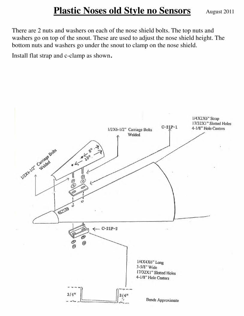
August 2011 Plastic Noses old Style no Sensors
There are 2 nuts and washers on each of the nose shield bolts. The top nuts and
washers go on top of the snout. These are used to adjust the nose shield height. The
bottom nuts and washers go under the snout to clamp on the nose shield.
Install flat strap and c-clamp as shown.

25
August 2011 Drago Corn Head Nose Shield Placement
Mount nose shield as shown below. Remove 4 bolts that fasten sensor assembly
onto the bottom of the snout. Remove sensor assembly from snout, remove and
discard front bolt and nut from sensor assembly. Drill holes in snout as shown.
Mount nose shield using 1/2” nut & washer provided.
There are 2 nuts and washers on each of the nose shield bolts. The top nuts and
washers go on top of the snout. These are used to adjust the nose shield height.
The bottom nuts and washers go under snout to clamp on noses shield.
At this time install and tighten back nut and washer only. Reinstall sensor
assembly under snout. The front bolt on nose shield should go through hole in
sensor assembly. Install and tighten front nut and washer on nose shield.
6”
11-3/4”
Drill 7/16” hole
Drill 9/16” hole

26
August 2011
8-3/4 hole centers
Use existing front 3/8 hole
Drill 9/16 hole back 8-3/4”
John Deere 600 series heads w/poly snouts
Mount nose shields as shown. The sensor Assembly will need to be removed
in order to fasten the 1/2” washer & nut onto the rear bolt of the nose shield
underneath. After installation reinstall the sensor Assembly.
There are 2 nuts and washers on each of the nose shield bolts. The top nuts
and washers go on top of the snout. These are used to adjust the nose shield
height. The bottom nuts and washers go under the snout to clamp on the nose
shield.
Note: If plastic wear protector is used please remove in order to remove front
3/8 bolt then reinstall and drill wear protector inline with existing hole.
3/8 x 3
1/2x6-1/2
3/8” bolt is
1-1/2” from
the end

27
Notes

28
ROLL-A-CONE MFG. CO.
7655 Rall-A-Cane Rd Tulia , TX 79088
Phone, 806·668·4722 Fax, 806-668·4725
Web Pagel www.roll· a-cone E-mail: [email protected]
To Amarillo
II ~ • Canyon
H',,(onl'~''''''' Vigo Park
W 83 II-'-.,FM-r-26_698 __ .:.F::M,,'.::46"---'.:...._
i! * ROU-A-CONE RoII-A·Cone Road
Dimmitt .~-==.-----IH TULIA S 1 wy ""R'WV'1i6. i V~rton
See Ral~A-Cone Mfg. or Your Ral~A-Cone aealer
for all your Farm Equipment Needs
Ell!' 7.. j .. ,
To Lubbock
If Taking 1.27 South From Amarillo:
• Take: Exit 83 (FM 2698) and cross b;J.ck ovcr the: over-pu,\; heading East
• Go Eau4-1I2 miles on FM 2698 • Turn right (SoUlh) OntO FM 146 and go
3 miles • Turn left (East) at the: RoII·A-Cone sign
and go 2· 1/2 miles on Roll -A·Cone Raod
If Taking 1.27 North From Lubbock:
• Tau Exit 74 :md follow H~'Y 86 signs imo Tulia
• In Tuli:t turn right (East) :lIthe (irS! blinking caution ligllllO follow Hwy 8G
• Go through downtown and :11 Junction 146IUm lefl OntO PM 146 North
• Turn back right (East) :lIthe: RoIl·A· Cone sign and go 2-1/2 miles on RolI·A· Con~ Road