Embed Size (px)
Citation preview

Project Plan
COMBINE SWATH-WIDTH CONTROLLERWITH YIELD MONITOR AND TIME DELAY
OPTIMIZATIONS
02/27/2000
Team Code: DEC 00-09
Client: Dr. Graeme Quick, Section LeaderAgriculture and Biosystems Engineering Power& Machinery Laboratory
Advisors: Professor Degang Chen, EE/CprEProfessor Ralph Patterson, EE/CprE
Team: Peters, Matthew Richard, CprEWebb, Stephen Edwin, CprEFajemisin, Babatunde O., EEKo, Chia-Yin, EEMertz, Jacob Jon, EENguyen, Ninh D., EEOtis, Ryan D., EE
i
Table of Contents
ABSTRACT ....................................................................................................................... 1
ACKNOWLEDGEMENT................................................................................................ 1
DEFINITION OF TERMS............................................................................................... 2
INTRODUCTION............................................................................................................. 6GENERAL BACKGROUND .................................................................................................. 6TECHNICAL PROBLEM ...................................................................................................... 7OPERATING ENVIRONMENT.............................................................................................. 7INTENDED USER AND USES .............................................................................................. 7ASSUMPTIONS AND LIMITATIONS..................................................................................... 8
Assumptions................................................................................................................. 8Limitations................................................................................................................... 8
DESIGN REQUIREMENTS............................................................................................ 9DESIGN OBJECTIVES......................................................................................................... 9FUNCTIONAL REQUIREMENTS .......................................................................................... 9DESIGN CONSTRAINTS.................................................................................................... 10MEASURABLE MILESTONES ........................................................................................... 11
END PRODUCT DESCRIPTION................................................................................. 12
APPROACH AND DESIGN .......................................................................................... 12TECHNICAL APPROACHES .............................................................................................. 12TECHNICAL DESIGN ....................................................................................................... 13TESTING DESCRIPTION ................................................................................................... 13RISKS AND RISK MANAGEMENT..................................................................................... 14
FINANCIAL BUDGET .................................................................................................. 15
PERSONAL EFFORT BUDGET.................................................................................. 16
PROJECT SCHEDULE ................................................................................................. 20PLANNING / RESEARCH .................................................................................................. 20DOCUMENTATION/PRESENTATIONS................................................................................ 20DESIGN........................................................................................................................... 21IMPLEMENTATION .......................................................................................................... 21TESTING ......................................................................................................................... 21ASSEMBLY ..................................................................................................................... 21
ii
PROJECT TEAM INFORMATION ............................................................................ 23TEAM MEMBERS ............................................................................................................ 23FACULTY ADVISORS....................................................................................................... 23CLIENT ........................................................................................................................... 24
SUMMARY...................................................................................................................... 24
REFERENCES................................................................................................................ 24

iii
List of Figures
FIGURE 1: CASE IH AFS 2100 COMBINE ............................................................................. 2
FIGURE 2: GPS INFORMATION GATHERING SYSTEM ............................................................. 3
FIGURE 3: SWATH WIDTH .................................................................................................... 4
FIGURE 4: CASE AFS YIELD MONITOR ................................................................................. 5
FIGURE 5: GANTT CHART FOR PROJECT SCHEDULE............................................................ 22

iv
List of Tables
TABLE 1: FINANCIAL BUDGET............................................................................................ 15
TABLE 2: PERSONAL EFFORT BUDGET ............................................................................... 17
TABLE 3: TASK ASSIGNMENT AND TIME ESTIMATION ....................................................... 18
TABLE 4: PERSONAL EFFORT TRACKING........................................................................... 19

1
Abstract
Farmers use combines on their fields to perform the complex operations necessary toeffectively harvest crops. Unfortunately, fields are not uniform and the adjustments thatoptimize the operation at the beginning of a field may be distinctly sub-optimal after onlya few feet of harvesting. These varying field conditions may result in the damage andloss of significant amounts of a harvested crop. While the farmer can make some of theseadjustments manually, an automatic feedback control system would provide moreefficient and effective changes to the combine parameters thereby achieving optimaloperation.
This team project will focus on the design of the automatic swath-width controller linkedto the yield monitor. This controller will help to automatically adjust the combineprocessing unit to account for different swath-widths for uneven field terrain therebyensuring greater yield monitor accuracy for crop density.
The project will be completed in two parts. First, the critical control parameters must beidentified and an effective control system must be designed, built and tested. Second,research will be performed to determine the delay time of the crop through the combinesystem. The delay time analysis will allow crop densities to be determined moreaccurately.
At present there are no feasibility results since testing of the actual concept has not beenperformed. By completing the project outlined above, farmers will be able to analyzetheir fields more precisely and potentially harvest at a faster rate.
Acknowledgement
The team would like to recognize the senior design course coordinators who have raisedthe level of the senior design activities. The team would like to acknowledge ouradvisors, Professor Patterson and Professor Chen who have greatly assisted in the detailsconcerning this project. A special thanks is due to Dr. Graeme, who significantly helpedin understanding the concepts and ideas that govern the project as well as the importanceof agricultural engineering logistics in a farming society. Agricultural graduate studentBrian Hollatz has also helped a good deal by providing the team with information andreference material.

2
Definition of Terms
• Combine: An agricultural machine that is a "combined" harvester-thresher. Beforecombines were invented, grain crops were harvested along with all of the plantmaterial and then the grain was threshed and separated from the plant material.Combines collect much of the material and then leave all but the actual grain in thefield. A photograph of an actual combine is shown in Figure 1 [1].
Figure 1: Case IH AFS 2100 combine
• Combine head: The part of the combine that detaches the plant material from theground and feeds it into the combine for threshing and separation. Heads aredifferent for different crops, and they detach plant material and grain in differentways.
• Crop width: Same as swath width.
• Cutter bar: The mechanism that cuts the plant stem before it is fed into the combine.Currently most machines use a set of reciprocating blades inside a set of stationaryguards. The guards serve as a counter edge for the cutting edge of the blade.
• Delay time: The amount of time that grain or other crop plant material takes to fromone system of a combine to another. It is of most of interest to measure the time fromwhen the crop enters the head to when it reaches the storage bin.
• DGPS - Differential GPS: Same as GPS except it uses at least one more satellite. Itis accurate to much smaller distances than regular GPS. Many newer systems arecapable of DGPS but use it only when enough satellites are available.

3
• Feed rate controller: A control system that monitors the throughput at differentplaces in the combine. Each system of a combine has a feed rate at which it operatesat maximum efficiency. A feed rate controller attempts to keep the throughput of allof the individual systems nearest to optimum at all times. For example, if a large slugof material comes into the machine very quickly, the controller would slow down ortemporarily divert the feeding to keep the threshing system at optimum capacity. Itmay also indicate to the combine operator when the combine is at optimum capacity.
• GPS - Global Positioning System: A satellite communications network that use atleast three satellites to locate a position on earth. Combines generally use GPSreceivers that can be integrated with yield monitors to create maps of yields ofdifferent areas of fields. These maps help farmers determine management practicesfor their fields such as where to apply more fertilizer, different fertilizer, moredrainage, etc. A diagram showing how GPS relates to combines is shown in Figure 2[1].
Figure 2: GPS information gathering system

4
• Swath Width: The width of crop that the combine is cutting in one pass. This appliesonly for crops that are not harvested in individual rows, but are cut off in swathes.Examples are oats, wheat, rice, and often soybeans. See Figure 3 for a visual diagramillustrating this term.
Figure 3: Swath Width
• Throughput: The capacity of the combine, often expressed in the number of metrictons of grain harvested per hour. Usually it refers to grain only, but it can also meanthroughput of MOG (material other than grain).

5
• Yield monitor: A monitoring system that tells the operator what the yield of thecrop is as the combine is running. Most yield monitors compensate for varyingmoisture content and read out directly in bushels per acre. Well-calibrated yieldmonitors are often very accurate. A photograph of an actual in-cab yield monitoris shown in Figure 4 [1].
Figure 4: Case AFS yield monitor

6
Introduction
General background
Combines are an integral part of the modern farmer’s agricultural business. Manyobstacles make the process of harvesting crops a difficult and technically complexprocedure. This project helps to address some of the current limitations in combineharvesting by providing the farmer more accurate information. The increased precisionof information gathered by a combine will provide the farmer with the means of makingmore informed decisions regarding his business. The information provided to the farmerwill take two forms, real-time information and stored information to later be assessed.This project addresses these two forms of information in two main subcomponents, theautomatic swath-width monitor and the yield monitor calculations.
The automatic swath-width monitor and controller included in this project will potentiallybe a significant addition to the combine in terms of the throughput performance measure.Sensors correctly positioned on both sides of the cutter bar of the combine will determinethe distance between the crop being harvested and the end of the cutter bar. This sensorinformation will be fed into a centralized control unit that will notify the driver ofadjustments to be made in position to improve crop alignment on the cutter thusincreasing throughput. If the centralized control unit is in automatic mode, the combinepositioning will be automatically altered to improve crop alignment on the cutter bar andthe driver will be notified of changes that are made.
With the advent of GPS (Figure 2), modern combines house a yield monitor that tracksthe amount of crop (grain, corn, etc.) harvested at one location in the field. Thisinformation can later be downloaded for analysis. Currently, yield monitors are designedto assume that the full swath width of the combine head is taking in crop, which is notalways the case. An additional link that directs more accurate input into the existingcombine yield monitor will provide a better depiction of crop density and yield for theparticular region being traversed. This also will allow for a more accurate representationof yield and crop density when the data is later collected from the yield monitor (Figure4).
Yield monitors assume an estimated value for the delay-time it takes for the product toget from the combine head into the storage bin. This affects how the appropriate yield isassigned to the correct location in the field. To further improve the accuracy of thecombine yield monitor, the project will research but may not implement delay calculationtechniques with the aid of miniature transmitters. The tiny transmitters, small enough tobe placed on and track an average honeybee, will broadcast unique signals to a receiver.The receiver will track how long the transmitters take to travel from the front (cropintake) of the combine to the storage bin in the rear of the combine. The analysis of theresults may bring more insight into the delay of the harvested crop to arrive in the bin.This allows for additional refinement of combine yield monitor signals thus providing aneven more accurate depiction of crop density for the region being traversed.

7
Technical Problem
Sensor alternatives shall be explored to optimize the output for the application andenvironment. All sensor input and control output signals will be sent using a yet to bedetermined guided transmission media. The centralized control unit will communicatewith the sensors to gather and process necessary information. User output will be on adisplay targeted for the combine driver. The centralized control unit will also sendappropriate signals, when appropriate, to existing combine positioning control inputs tomodify the combine’s position. Additionally, the centralized control unit will interceptthe appropriate existing yield monitor signals and modify them to reflect the currentswath width being utilized by the combine. Both battery and existing combine powerfacilities will be evaluated as possible options for source power to the devices previouslymentioned.
Feasibility studies will be conducted concerning the likelihood of the transmittersgenerating quality data. Receiver alternatives shall be explored as to precisely gathertransmitter information. The transmitter data shall be analyzed and will be integrated intocombine yield monitor calculations through the centralized control unit if appropriate.
Operating Environment
The resultant end product will be subjected to potentially harsh environmental conditions,as it will physically reside on the combine. This includes, but is not limited to, hotweather, cold weather, heat from surrounding machinery, the forces due to unevenground terrain or vibrating portions of the combine, condensation, rain, frost, snow, wind,and reasonable pressure applied by the human user during maintenance and use.
Intended User and Uses
The intended user of the end product will be a farmer who utilizes a combine to harvesthis/her crops. The product will be used to complement the existing functionality of thecombine by providing feedback as directions or automatic adjustments to properly alignthe combine relative to the field in order to optimize throughput. The product will alsobe used to provide more accurate results within the existing combine yield monitor.

8
Assumptions and Limitations
This section lists the assumptions and resource limitations that must be considered forthis project. They are explained in further detail below.
Assumptions
• The user is familiar and competent with the operation of a combine
• The display output should be brief and easily understandable as the farmerwill be quite busy operating other combine parameters.
• The combine used for implementation will be available after the summer toobserve and modify.
• Information concerning the yield monitor and the design specifics of ourcombine will be available.
Limitations
• The product will only be fully functional when properly installed on the samecombine model on which it will be tested.
• The display output to the user will be of a compact yet visible size therebylimiting the amount of information that may be simultaneously displayed tothe user.
• The sensors will be limited to a combine cutterbar attachment and will notfunction with alternate attachments such as a corn head.
• The knowledge of combines and other farm related machinery within thegroup will be limiting to initial project progress.
• The cost and availability of combines limits the testing and design to the
single combine provided for this project.
• The team will be relying on outside sources for the design specifics regardingthe combine.

9
Design Requirements
Design Objectives
The objective of this project is to provide the client with more information regarding theswath-width utilization of the combine and to also increase the precision of the yieldmonitor. The three main objectives below are the focus of this project’s design.
• Sensors: The sensors are used to gather information concerning the distance ofthe crop being harvested to the edge of the cutterbar. There will be twosensors, one for each edge of the cutterbar. Environmental and functionalperformance of various sensors needs to be evaluated in order to determine theoptimal sensor types. Additional circuitry may be required to format thesensor output so that it is usable as input to the centralized control unit.
• Microcontroller based centralized control unit: The functions of this unit are
to accept the data collected by the sensors and the yield monitor input andthen generate appropriate output signals. The outputs will include a serial linkto the LCD display and the necessary outputs to the combine positioningcontrol input as well as combine yield monitor inputs. The output to the LCDshall be formatted to update the user as to the current status of combineparameters and adjustments that have been made.
• Microcontroller options: Microcontrollers must be evaluated to select anoptimal microcontroller that meets the stated needs of this project. Userinterface options will also be evaluated in regards to the requirements. Themicrocontroller will most likely be programmed in C to perform the tasksmentioned, although other languages will be considered.
Functional Requirements In order to satisfy the client and meet the objectives of this project, the delivered productmust adhere to the functional requirements outlined below. Microcontroller based centralized control unit:
• Shall be able to handle and process a sufficient number of inputs provided bysensors, yield monitor inputs, and user inputs.
• Shall be able to handle and process a sufficient number of outputs for the
LCD, combine positioning control, and combine yield monitor. • Shall have a memory sufficient for long-term storage of instructional code.

10
• Shall be able to accept user input as to disable functionality temporarily.
LCD user interface:
• Shall be informative of the current state of the system, various combineparameters, and actions that have been taken.
Sensors:
• Shall be capable of collecting desired data within error tolerances (to bedetermined) and transmit signals back to the centralized control unit such thatthey are intelligible by the control unit.
Design Constraints
All devices designed in this project will be done so with the intent of being installed onthe provided functional combine. The devices must therefore be able to perform underthe potentially harsh environmental conditions the combine may be subjected to. Thedevices in this project also must be able to derive their power from the available poweroutputs present on the combine. Devices are therefore restricted to the power outputavailable on the combine.
The design in this project will be constrained to the combine used for testing. Theexisting yield monitor in the combine will be interfaced to
Centralized control unit: • The unit must be sufficiently compact to fit within the combine structure
without obstructing any moving parts or inconveniencing the human operator.
• The unit will be designed with the intent of interfacing to the existing yieldmonitor in the combine.
Sensors
• All sensor design will be done with the intent of it’s eventual physicalmounting on the cutter bar of the combine.
User interface:
• The user interface must be visible within the combine’s cockpit under fieldsunlight conditions.

11
• The viewable area and resolution of the user interface must be sufficient todisplay all desired feedback information to the user without requiring userinvolvement.
• The user interface must be small enough so as not to obstruct other combine
controls or inhibit the operational ability of the user. Measurable Milestones
• All sensor alternatives have been explored and the best sensor candidate hasbeen selected.
• All microcontroller options for the centralized control unit have been explored
and the best microcontroller candidate has been selected.
• All power alternatives have been explored and a power source has beenselected and designed to accommodate for the centralized control unit andsensors.
• The interface between the microcontroller and all sensors has been established
and is functional.
• All necessary sensors have been designed and tested to provide meaningfuland sufficient information as to their requirements.
• Fully operational instructional program code for the microcontroller-based
centralized control system has been implemented and is able to process sensorsignals and provide the proper output to the display.
• Interface to the existing yield monitor has been researched and the proper
code has been implemented into the centralized control unit to provide moreaccurate input to the combine yield monitor.
• Transmitter feasibility analysis is complete and the decision has been made
concerning whether to progress with data collection.
• Transmitter data has been collected and analyzed. Centralized control unitcalculations have been updated if applicable.
• Field test of product has been conducted and results have been recorded.
• Debugging is complete and product is fully operational!

12
End Product Description
The end product for this project is a control and measurement system for a combine. It isto monitor and control the swath width of a combine during the harvesting of variouscrops. Sensors and control hardware will measure the percentage of swath width beingoccupied, alert the operator, apply necessary corrections to yield monitor calculations,and possibly initiate corrective actions to maintain a fully utilized swath at all times. Alsoincluded, would be the research performed on the derivation of the delay time of the cropthrough the combine system so that the throughput can be more accurately measured. Thedesired end product will aid the farmer in more efficiently harvesting his crops andimprove the accuracy of field mapping. This is accomplished by better utilization of thefull swath length and more precise delay calculations for the yield monitor.
Approach and Design
Technical Approaches
The approach taken regarding this project will be to first research and gather pertinentinformation concerning the details of the previously identified possible main components.Evaluations with the aid of the research information will be conducted in order to selectthe appropriate components for the application described.
Combine parameters will need to researched in order to properly consider the ultimateoperating considerations for each component as outlined below.
Swath Width Monitor and Control:
• The technical approach for this section of the project will be the investigation,selection, and implementation of sensors, the control unit, and output.
• The sensors will measure the unused section of the combine head duringharvesting. These will have to be rugged to hold up to the operatingenvironments in which they will operate.
• The control unit will manipulate the output signal of the sensors into ausable form that the combine yield monitor can use.
• The output will be a component that the farmer may find desirable. It is adisplay so the farmer will know what corrections that are being made.

13
Yield Delay:
• Research and experimental results will determine the signals necessary to besent into the yield monitor.
• The approach concerning the yield delay is to consider swath width and sensethe average delay time of the crop from entering the head until it reaches thestorage bin on the combine.
Technical Design
The swath-width controller design consists of the following areas:
• Sensors: This includes the proper placement and type of sensor used tomeasure the swath width with the greatest accuracy.
• Control unit: This includes taking the signal put out by the sensors,calculating the width, and generating an output that is usable to the yieldmonitor.
• Yield delay: This will be analyzed through the evaluation of the transmitters.The delay time will the calculated by a control unit that is tied to the receivers.
Testing Description
Testing criteria will consider each main component individually. A basic description ofthe testing that will commence for each main component is outlined below.
Sensors:• The sensors will be tested outdoors in a harvesting environment.
• Output signal variance with crop distance from the sensor will be analyzed tosee if proper results may be obtained within a tolerance to be determined.
• Output signal quality will be analyzed for digital signal processing candidacy.
• Output signal quality will be analyzed in regards to the requirements forcentralized control unit input.
Centralized Control Unit:• This component will be individually tested using phantom input signals to see
if proper output signals are generated as desired within the time allotted.

14
User Interface:• The user interface will be tested by a combine operator to see if it meet’s their
satisfaction.
Yield Monitor Data:• The applicable standard input signals into the yield monitor will be swapped
with those provided by the centralized control unit during a field harvest testin which the swath width will not be fully utilized.
• Results after a harvest test will be obtained from the yield monitor andunmodified results will be compared with those modified by the centralizedcontrol unit for accuracy.
Risks and Risk Management
The newly proposed nature of this project brings forth a fair amount of rise.Additionally, the project requires significant feasibility analysis for each maincomponent. The section below addresses possible project risks and how they shall behandled.
• Loss of a team member: Given the extensive milestones for this project, theloss of any team member is a significant risk. Tasks will need to beredistributed to account for slack left by a person’s absence from the project.Yield monitor delay calculations, being of secondary priority, will besacrificed if a person’s absence increases the personal effort budget beyondit’s allocation.
• Failure of technical approaches: Research gathered will be readily availablefor analysis in order to attempt a different approach.
• Inadequate budget: Search for outside sources for funding or donations ofmaterials. Consider other less expensive options for components.
• Inadequate time: Increase the personal effort budget if additional time isavailable later. Seek deadline extensions or remove secondary priority yieldmonitor delay calculations.
• Lack of understanding: Consult with a specialist or a professor in requiredfield.
• Lab hazards: Always work in a group of two in the lab.

15
Financial Budget
The table below (Table 1) outlines the financial expenditure of the project. The hardwareincludes sensors, a centralized control unit, micro-transmitters, and miscellaneoushardware at present. The software includes C and Assembly programming language toolpackages.The estimate was obtained by speaking with the client, groups, and persons withexperience in ordering the parts similar to those specified. Observations of previousproject budgets seemed to indicate a tendency for costs to be underestimated. Therefore,due to the uncertainty at this point, the estimate was meant to be liberal and provideadditional funds if later found to be necessary.
Table 1: Financial BudgetItem Source of
FundingQuantity Original
Estimated CostActual Cost
Micro-transmitters
Dr. GraemeQuick
100Approx.
$2000
Sensors Team ordonation
2Minimum
$150
CentralizedControl Unit
Team ordonation
1Minimum
$500
Wiring,mounting, &
miscellaneoushardware
Team Unknown $150
Total hardwarecost
N/A N/A $2800.00
ProgrammingTools
Team ordonation
Unknown $200
Total softwarecost
N/A N/A $200.00
Telephone andresearch
Group Unknown $40.00
Printing (poster) University 1 $100.00
Total cost N/A N/A $3140.00

16
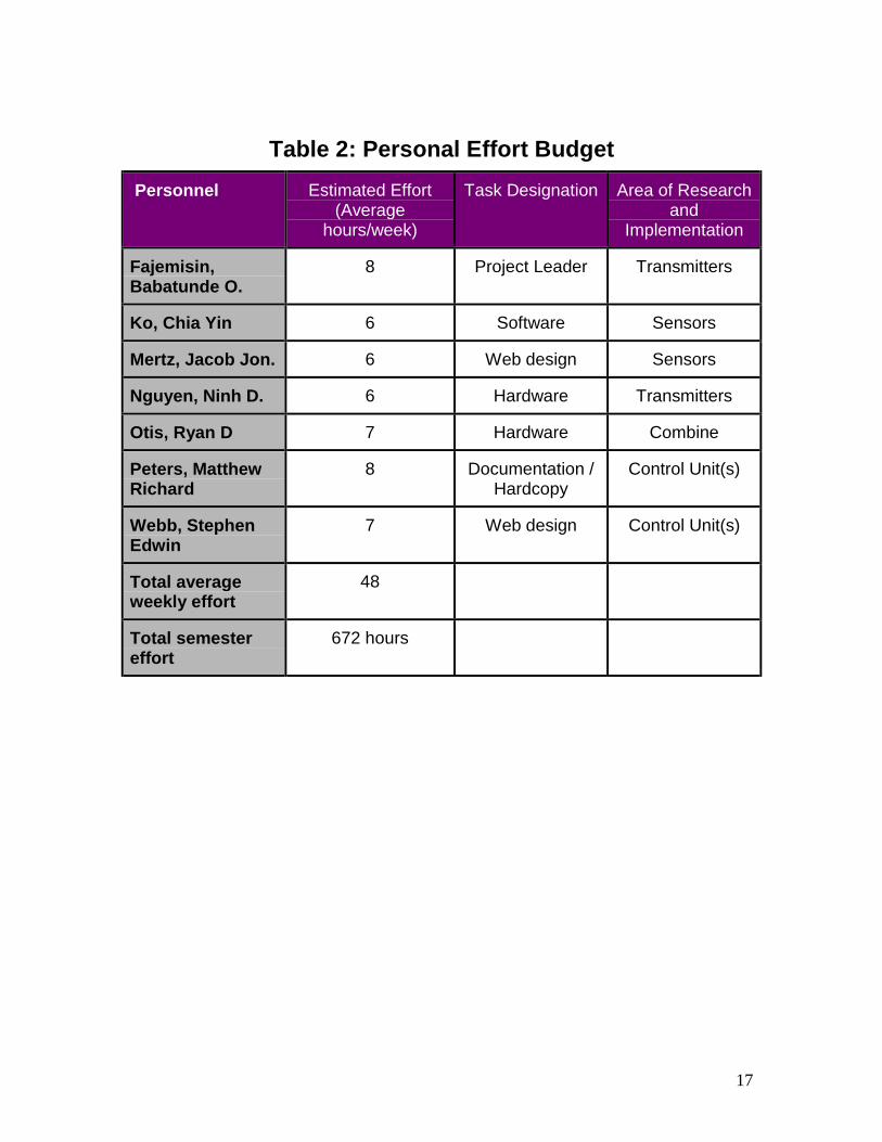
Personal Effort Budget
The personal effort budget table presented below (Table 2) designates two members toeach main task designation in order to effectively accomplish each task in it’s entirety.By assigning two group members to each major task subsection we provide someassurance that a task leader will always be present even if a group member is lost duringthe course of the project.Since this is a newly formed project, it will require a good deal of time devoted toresearch in order for the project to complete successfully. Therefore, effort estimateshave been assigned liberally with considerations taken regarding the group member’stask designation. The estimates were obtained by analyzing the personal effort budgetsof past projects. Past project effort budgets were analyzed with their scope, success, andsize taken into relative consideration.Task designations were assigned on a skill and voluntary basis. The voluntary basisensures that each team member is in a subsection of the project that they are mostinterested in. This method of designation helps to assure productivity and projectdedication as well as expertise.The budget is meant to be dynamic to accommodate for unexpected events. As tasks andschedules change throughout the duration of this project, the team will dynamicallyassign tasks to different group members. The personal effort budgets were estimatedwith the intent of possible growth.
17
Table 2: Personal Effort Budget Personnel Estimated Effort
(Averagehours/week)
Task Designation Area of Researchand
Implementation
Fajemisin,Babatunde O.
8 Project Leader Transmitters
Ko, Chia Yin 6 Software Sensors
Mertz, Jacob Jon. 6 Web design Sensors
Nguyen, Ninh D. 6 Hardware Transmitters
Otis, Ryan D 7 Hardware Combine
Peters, MatthewRichard
8 Documentation /Hardcopy
Control Unit(s)
Webb, StephenEdwin
7 Web design Control Unit(s)
Total averageweekly effort
48
Total semestereffort
672 hours

18
Effort estimates for each major task in the project were made to help subdivide the timebudget. By making time estimates for each major task the team may determine thephases in the project that are impeding progress. Table 3 below shows the personsresponsible for each major task, the time estimate, and the actual time taken to completeeach task.
Table 3: Task Assignment and Time EstimationAttributes Project
PlanResearch Poster Design
ReportOral
PresentationImplementation Testing End
ProductDelivery
TaskLeader
Peters Babatunde Webb To beDetermined
To beDetermined
To beDetermined
To beDetermined
Babatunde
OthersResponsible
All All OtisMertz
To beDetermined
All All All All
Total TimeEstimation:
(hours)
80 280 60 100 50 200 400 30
PercentCompletion
100% 5% 0% 0% 0% 0% 0% 0%
ActualTime
Taken:(hours)
70

19
Table 4 below is meant to assist the team in tracking actual personal effort against thepersonal effort budget. The table will be filled in as the semester progresses. Aftertracking actual personal effort against the estimate for the first semester, the group shallanalyze the data and revise personal effort estimates for the second semester accordingly.
Table 4: Personal Effort Tracking
Project Plan
Research
Poster
Design Report
Oral Presentation
1/30 2/6 2/13 2/20 2/27 3/5 3/12 3/19 3/26 4/2 4/9 4/16 4/23 4/30 5/7Fajemisin,Babatunde O.Ko, Chia Yin
Mertz, Jacob Jon.
Nguyen, Ninh D.
Otis, Ryan D
Peters, MatthewRichardWebb, StephenEdwin
20
Project Schedule
The project schedule has been broken down into tasks as outlined below:
Planning / Research• Research combine operation: Research shall be conducted to obtain a better
understanding of combine operation. This will aid the project in permitting us toconsider how modifications to the combine will affect performance.
• Identify control parameters: Control parameters shall be identified so thatresearch may be conducted as to how parameter variation affect performance.
• Research existing electronics: It will be important to have information regardingexisting electronics so that they may be utilized to their full potential andunnecessary additions to our design are avoided.
• Identify possible sensor technology: Research shall be conducted to establish thesensor technology that will be most suitable for our application so that design maybecome more focused.
• Research miniature transmitters: Feasibility analysis shall be conducted todetermine whether additional time should be allocated for the implementation ofyield delay optimizations.
• Identify possible control unit(s): Research shall be conducted to establish thecontrol unit(s) that would be most suitable for our application so that design maybecome more focused.
Documentation/Presentations• Project plan: Introduces the project and how it shall be conducted.
• Poster: A visual poster used to explain our project and it’s implications to aneducated audience.
• Design report: Outlines the initial design of our product.
• Final report: Report on the objectives met in the project, the project outcome, andwhether additional work should be conducted.
• Presentation to client: Present the project approach and design to the client toinform the client of project progress and obtain feedback.
• Final presentation: Present the objectives met in the project, the project outcome,and whether additional work should be conducted.

21
Design• Select control unit: The control unit shall be selected for programming and
interfacing with the sensors and yield monitor.• Select sensors: The sensors shall be selected for integration with the control unit.
• Hardware design: Time shall be allocated to design the hardware to meet desiredrequirements specifications.
• Software design: Time shall be allocated to design the software to meet desiredrequirements specifications.
Implementation• Sensors: The sensors shall be mounted and tested according to the design and
testing plan.
• Control Unit: The control unit shall be constructed and programmed according tothe design and testing plan.
Testing• Sensors: Sensor output shall be individually tested for suitability for control unit
input.
• Transmitters: Transmitters shall be tested if they pass the feasibility analysis.
• Control Unit: The control unit shall be individually tested for expected outputgiven certain input permutations.
• Overall System: The integrated system shall be tested to ensure properinterfacing among major components.
Assembly• End of product delivery: The end product shall be assembled to be delivered to
the client.
To illustrate how the tasks above will be addressed in regard to time, please refer to theGantt chart in Figure 5.

22
Figure 5: Gantt chart for Project Schedule

23
Project Team Information
Team Members• Babatunde Fajemisin (EE)
Friley 4530 MeekerAmes, IA [email protected]
• Chia-Yin Ko (EE)2517 Jensen Ave. #337Ames, IA [email protected]
• Jacob Mertz (EE)4518 Hutchinson #22Ames, IA [email protected]
• Ninh Nguyen (EE)3507 W. Lincoln Way #10Ames, IA [email protected]
• Ryan Otis (EE)155-A University VillageAmes, IA [email protected]
• Matthew Peters (CprE)Wallace 9315 McCowenAmes, IA [email protected]
• Stephen Webb (CprE)Storms 5147 LovelaceAmes, IA [email protected]
Faculty Advisors• Dr. Ralph Patterson
326 Town EngineeringAmes, IA 50011Phone: 515-294-2428Fax: [email protected]
• Dr. Degang Chen3134 CooverAmes, IA 50011Phone: 515-294-6277Fax: [email protected]

24
Client• Dr. Graeme Quick
Agricultural & Biosystems Engineering200 Davidson HallAmes, IA 50011Phone: 515-294-1320Fax: [email protected]
Summary
The combine is a very complex and sophisticated machine used in today’s agriculturalfield. With the addition of the auto-width monitor and controller, the combine will beable to relay the actual width of product to the yield monitor and have an automated ormanual output to position the combine for maximum product intake. This increase tomaximum crop intake may potentially save the combine operator significant time sincethe entire combine capacity will constantly be utilized.
By conducting the research on the delay-time experiment mentioned previously, anaccurate delay time will be determined and yield monitor data will be allocated correctly.The successful completion of this project will also bring about significant improvementsin yield monitor accuracy thereby giving farmers a better analysis of their fields for use inoptimal crop production.
References
[1] Case III: Advanced Farming Systems, Case Corporation, Racine, Wisconsin,1997.
[2] Hollatz, Brian, Graduate Assitant, Agricultural & Biosystems Engineering,Iowa State University