Embed Size (px)
Citation preview

ZHANG ET AL . VOL. 8 ’ NO. 5 ’ 4571–4579 ’ 2014
www.acsnano.org
4571
April 22, 2014
C 2014 American Chemical Society
Core-Spun Carbon Nanotube YarnSupercapacitors for WearableElectronic TextilesDaohong Zhang,†,‡ Menghe Miao,†,* Haitao Niu,§ and Zhixiang Wei^
†CSIRO Materials Science and Engineering, P.O. Box 21, Belmont, Victoria 3216, Australia, ‡Key Laboratory of Catalysis and Materials Science of the State EthnicAffairs Commission & Ministry of Education, South-Central University for Nationalities, Wuhan, Hubei Province 430074, China, §Institute for Frontier Materials,Deakin University, Geelong, Victoria 3220, Australia, and ^National Center for Nanoscience and Technology, Beijing 100190, P. R. China
Flexible batteries and supercapacitorsare desirable power sources for light-weight, portable, and wearable elec-
tronics that have become symbolic ofmodern life. These flexible energy storagedevices may be of one-dimensional (1D, orlinear) or two-dimensional (2D, or planar)architectures.1�3 Planar supercapacitors aremostly built on metal sheets, plastic films,papers, and textile fabric substrates.1,2,4,5
After impermeable layers of activematerials,separation membranes, and current collec-tors are deposited, the 2D supercapacitorsoften become quite bulky, their flexibilitydeteriorates considerably, and the resultingsupercapacitors lose their permeability toambient air and perspiration moisture, allof which are essential for wearer comfort.6�9
Theseproblemswill becomemajor concernsif the devices cover a large area of theclothing system.In comparison, linear energy storage de-
vices may be woven or knitted, alone orin combination with textile yarns, into fab-rics that are both robust and comfort-able to wear.10�13 The freedom for body
movement (fabrics can be bent or foldedeasily) and permeability to air and moisture(transport of body sweat vapor) in wovenand knitted fabrics originate from their in-terlaced structures in which the constituentyarns are free to move relative to eachother, and there are through-thickness holesformed between the constituent yarns.The fineness of linear supercapacitors rangefrom much finer than extrafine count textileyarns used in high quality handkerchiefs10,11
to very coarse count yarns used in wintersweaters and blankets.14
Linear supercapacitor devices can bebuilt on linear substrates such as metalwires,7,11,14�16 plastic/rubber wires,17,18 car-bon fibers,14 carbon nanofibers,19 carbonnanotube (CNT) yarns,7,10,11,20�23 CNT com-posite fibers,11,24 graphene fibers,25 and gra-phene composite fibers.26 These substratesserve as the reinforcement as well as thecharge collector for the active materials.Nonconductive substrates may be coatedwith conductive (e.g., metal) materials sothat they can act as current collectors foractive materials.17 Active materials used in
* Address correspondence [email protected].
Received for review January 8, 2014and accepted April 22, 2014.
Published online10.1021/nn5001386
ABSTRACT Linear (fiber or yarn) supercapacitors have demonstrated
remarkable cyclic electrochemical performance as power source for wearable
electronic textiles. The challenges are, first, to scale up the linear super-
capacitors to a length that is suitable for textile manufacturing while their
electrochemical performance is maintained or preferably further improved
and, second, to develop practical, continuous production technology for
these linear supercapacitors. Here, we present a core/sheath structured carbon nanotube yarn architecture and a method for one-step continuous spinning
of the core/sheath yarn that can be made into long linear supercapacitors. In the core/sheath structured yarn, the carbon nanotubes form a thin surface
layer around a highly conductive metal filament core, which serves as current collector so that charges produced on the active materials along the length of
the supercapacitor are transported efficiently, resulting in significant improvement in electrochemical performance and scale up of the supercapacitor
length. The long, strong, and flexible threadlike supercapacitor is suitable for production of large-size fabrics for wearable electronic applications.
KEYWORDS: supercapacitors . carbon nanotubes . core yarns . current collectors . nanotechnology
ARTIC
LE
ZHANG ET AL . VOL. 8 ’ NO. 5 ’ 4571–4579 ’ 2014
www.acsnano.org
4572
linear supercapacitors may be carbon nanoparti-cles,14,16,24 metal oxides,11,12,17,23 and conductingpolymers.10,13,21 Metal oxides and conducting poly-mers are high performance materials because of theirhigh pseudocapacitance and the capability to chargeand discharge at high rates.27�31 The electrochemicalperformance of pseudocapacitance materials canbe further improved when they are made into nano-wires, for example, polyaniline nanowires and ZnOnanowires.17,31
Carbon nanotubes are electrical double-layer capa-citor (EDLC) materials on their own. Vertically alignedCNT arrays (CNT forests) have an ideal mesoporousstructure for high electrolyte accessibility.32�34 Carbonnanotube yarns spun from CNT forests have excellenttextile properties (strong and flexible),35 and havebeen a popular substrate for constructing linearsupercapcitors.7,10,11,20�23 When used as a substrate,their high mechanical strength and stability can helpobviate degradation of mechanical and electrochemi-cal performances of conducting polymer caused byswelling and shrinking during the doping and dedop-ing processes.10,36 Linear supercapacitors based oncarbon nanotube yarns have demonstrated remarkablecyclic electrochemical performance over short lengths.Their performance decreases rapidly as the yarn lengthincreases. Although carbon nanotube yarns havemuch higher electrical conductivity37 than widely usedpseudocapacitancematerials as current collectors,38�41
their conductivity is still 100s of times lower than thatof metal wires. A key challenge is therefore to scaleup them to a length that is suitable for textile manu-facturing while their electrochemical performance ismaintained or preferably further improved.Here, we present an architecture that can greatly
scale up the length and significantly improve theelectrochemical performance of CNT yarn-based linearsupercapacitors. These are achieved by embedding avery thin metal wire (monofilament) in the center of acarbon nanotube yarn. In the core/sheath structuredyarn, the carbon nanotubes form a thin surface layerwith high electrolyte accessibility and much shorterroutes for transporting charges produced on the mainactive materials to the highly conductive metal core.In this way, charges stored along the length of thelinear supercapacitors can be transported at very highefficiency.Solid-state multiwalled carbon nanotube (MWCNT)
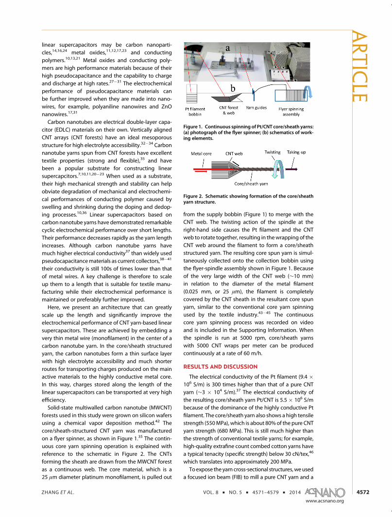
forests used in this study were grown on silicon wafersusing a chemical vapor deposition method.42 Thecore/sheath-structured CNT yarn was manufacturedon a flyer spinner, as shown in Figure 1.35 The contin-uous core yarn spinning operation is explained withreference to the schematic in Figure 2. The CNTsforming the sheath are drawn from the MWCNT forestas a continuous web. The core material, which is a25 μm diameter platinum monofilament, is pulled out
from the supply bobbin (Figure 1) to merge with theCNT web. The twisting action of the spindle at theright-hand side causes the Pt filament and the CNTweb to rotate together, resulting in thewrapping of theCNT web around the filament to form a core/sheathstructured yarn. The resulting core spun yarn is simul-taneously collected onto the collection bobbin usingthe flyer-spindle assembly shown in Figure 1. Becauseof the very large width of the CNT web (∼10 mm)in relation to the diameter of the metal filament(0.025 mm, or 25 μm), the filament is completelycovered by the CNT sheath in the resultant core spunyarn, similar to the conventional core yarn spinningused by the textile industry.43�45 The continuouscore yarn spinning process was recorded on videoand is included in the Supporting Information. Whenthe spindle is run at 5000 rpm, core/sheath yarnswith 5000 CNT wraps per meter can be producedcontinuously at a rate of 60 m/h.
RESULTS AND DISCUSSION
The electrical conductivity of the Pt filament (9.4 �106 S/m) is 300 times higher than that of a pure CNTyarn (∼3 � 104 S/m).37 The electrical conductivity ofthe resulting core/sheath yarn Pt/CNT is 5.5 � 106 S/mbecause of the dominance of the highly conductive Ptfilament. The core/sheath yarn also shows a high tensilestrength (550MPa), which is about 80%of the pure CNTyarn strength (680 MPa). This is still much higher thanthe strength of conventional textile yarns; for example,high-quality extrafine count combed cotton yarns havea typical tenacity (specific strength) below 30 cN/tex,46
which translates into approximately 200 MPa.Toexpose theyarn cross-sectional structures,weused
a focused ion beam (FIB) to mill a pure CNT yarn and a
Figure 1. Continuous spinning of Pt/CNT core/sheath yarns:(a) photograph of the flyer spinner; (b) schematics of work-ing elements.
Figure 2. Schematic showing formation of the core/sheathyarn structure.
ARTIC
LE

ZHANG ET AL . VOL. 8 ’ NO. 5 ’ 4571–4579 ’ 2014
www.acsnano.org
4573
Pt/CNT/PANI coated core/sheath yarn. The cross-sectional morphology of the pure CNT yarn is exhibitedin Figure 3a, in which randomly distributed voids arevisible. SEM images for the Pt/CNT/PANI core/sheathyarn taken at two stages of FIB milling are presentedin Figure 3b�d. The cross-section obtained from initialcoarse milling using a high beam current of 31 nA(Figure 3b) did not provide clear views in the core/sheath border region due to severe redeposition ofplatinum sputtering onto the newly formed sectionalface. To obtain a clear sectional face, the coarse-milledsection was further processed by “polish milling” at amuch lower beam current (2 nA). This produced clearsectional views in the core/sheath border regions(Figure 3c,d).There are no obvious differences between the
Pt/CNT core/sheath yarn and the pure CNT yarn in termsof CNT packing observed from the sectional faces.Enlarged views in Figure 3e,f show that pores betweenconstituent CNTs take different shapes, with themajority greater than 100 nm. These pores appear toorientate along the CNT length (following the generaldirection of the twist helices in the yarn) and are pre-sumably interconnected. The SEM images in Figure 3c,d also show that the platinum filament core (bright arcsegments at the lower corners of the images markedby “core”) is surrounded by the CNTs in the sheath.No gaps between the CNT sheath and the Pt core couldbe observed. Thiswas because the CNTwebwas tightly
wrapped round the Pt filament under tension duringspinning, resulting in compression between the twocomponents.The surface morphologies of CNT and Pt/CNT yarns
were examinedby scanning electronmicroscopy (SEM).The pure CNT yarn has a diameter of approximately16 μm (Figure 4a) with well-aligned CNTs on the yarnsurface. The as-spun Pt/CNT core/sheath yarn showsa diameter of about 29.5μmwith similar CNT alignmenton the yarn surface (Figure 4b).Typical textile processes require a yarn to slide
over machine parts, during which the yarn bendsand rubs against the parts. Such combined bendingand rubbing action can be simulated by a needle-and-pin arrangement shown in Figure S1 (SupportingInformation). Bymoving the latch needle up anddown,the yarn is bent and rubbed against the needle and thepins repeatedly while under a 10 cN/tex tension basedon the CNT component. The friction on the CNT sheathapplied by the needle and pins tend to tear the CNTsheath off from its metal filament core, a failure modeknown as sheath slippage in the textile industry.45 Theexperiment provides an indication of the interfacialstrength between the CNT sheath and the Pt core.SEM images of CNT/Pt core spun yarn specimens after60 cycles of rubbing test (60 up-and-down actions,giving a total of 120 rubs) are shown in Figure 4c�f.There were no signs of sheath slippage or sheath beingstripped off the Pt filament core. The rubbing actiononly caused some roughening of yarn surface, result-ing in some CNTs being lifted up from the yarn surface.This demonstrates that the interface between theCNT sheath and the Pt core is very strong. In the finalsupercapacitor, the CNT sheath is protected by thepolymer electrolyte coating (PVA�H3PO4); thus, theCNT sheath will not be rubbed against machine parts
Figure 4. SEM images of CNT yarn and Pt/CNT core/sheathyarn: (a) as-spun CNT yarn; (b) as-spun Pt/CNT core/sheathyarn; (c�f) Pt/CNT core/sheath yarn after 120 rubbingactions.
Figure 3. Yarn cross-sectional views: (a) cross-section ofpure CNT yarn; (b) cross-section of Pt/CNT/PANI core/sheathyarn resulted from coarse FIB milling; (c, d) core/sheathborder regions of Pt/CNT/PANI yarn after polish-milling,corresponding to the marked region in image b; (e, f)enlargements showing CNT bundles and pores betweenCNT bundles in the yarn cross-section.
ARTIC
LE
ZHANG ET AL . VOL. 8 ’ NO. 5 ’ 4571–4579 ’ 2014
www.acsnano.org
4574
directly during textile processing and CNTs will not belifted off like the uncoated yarn shown in Figure 4c�f.The CNT and Pt/CNT yarns were then coated in
polyaniline nanowire solution synthesized using aknown procedure with some minor modifications.29,47
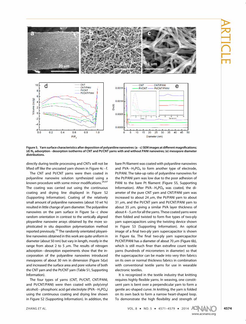
The coating was carried out using the continuouscoating and drying line displayed in Figure S2(Supporting Information). Coating of the relativelysmall amount of polyaniline nanowires (about 10 wt %)resulted in little change of yarn diameter. The polyanilinenanowires on the yarn surface in Figure 5a�c showrandom orientation in contrast to the vertically alignedployaniline nanowire arrays obtained by the more so-phisticated in situ deposition polymerization methodreported previously.10 The randomly orientated ployani-line nanowires obtained in this work are quite uniform indiameter (about 50 nm) but vary in length, mostly in therange from about 2 to 5 μm. The results of nitrogenadsorption�desorption experiments show that the in-corporation of the polyaniline nanowires introducedmesopores of about 30 nm in dimension (Figure 5d,e)and increased the surface area and pore volume of boththe CNT yarn and the Pt/CNT yarn (Table S1, SupportingInformation).The four types of yarns (CNT, Pt/CNT, CNT/PANI,
and Pt/CNT/PANI) were then coated with poly(vinylalcohol)�phosphoric acid gel electrolyte (PVA�H3PO4)using the continuous coating and drying line shownin Figure S2 (Supporting Information). In addition, the
bare Pt filament was coatedwith polyaniline nanowiresand PVA�H3PO4 to form another type of electrode,Pt/PANI. The take-up ratio of polyaniline nanowires forthe Pt/PANI yarn was low due to the poor adhesion ofPANI to the bare Pt filament (Figure S5, SupportingInformation). After PVA�H3PO4 was coated, the di-ameter of the pure CNT yarn and CNT/PANI yarn wasincreased to about 24 μm, the Pt/PANI yarn to about31 μm, and the Pt/CNT yarn and Pt/CNT/PANI yarn toabout 35 μm, giving a similar PVA layer thickness ofabout 4�5μmfor all the yarns. These coated yarnswerethen folded and twisted to form five types of two-plyyarn supercapacitors using the twisting device shownin Figure S3 (Supporting Information). An opticalimage of a final two-ply yarn supercapacitor is shownin Figure 6a. The final two-ply yarn supercapacitorPt/CNT/PANI has a diameter of about 70 μm (Figure 6b),which is still much finer than extrafine count textileyarns (hundreds of micrometers in diameter) so thatthe supercapacitor can be made into very thin fabricson its own or normal thickness fabrics in combinationwith conventional textile yarns for use in wearableelectronic textiles.It is recognized in the textile industry that knitting
requires highly flexible yarns. In weaving, one constit-uent yarn is bent over a perpendicular yarn to form agentle arc-shaped curve. In knitting, the yarn is foldedon its own back to form a narrow heart-shaped loop.To demonstrate the high flexibility and strength of
Figure 5. Yarn surface characteristics after depositionof polyanilinenanowires: (a�c) SEM images at differentmagnifications;(d) N2 adsorption�desorption isotherms of CNT and Pt/CNT yarns with and without PANI nanowires; (e) mesopore diameterdistributions.
ARTIC
LE
ZHANG ET AL . VOL. 8 ’ NO. 5 ’ 4571–4579 ’ 2014
www.acsnano.org
4575
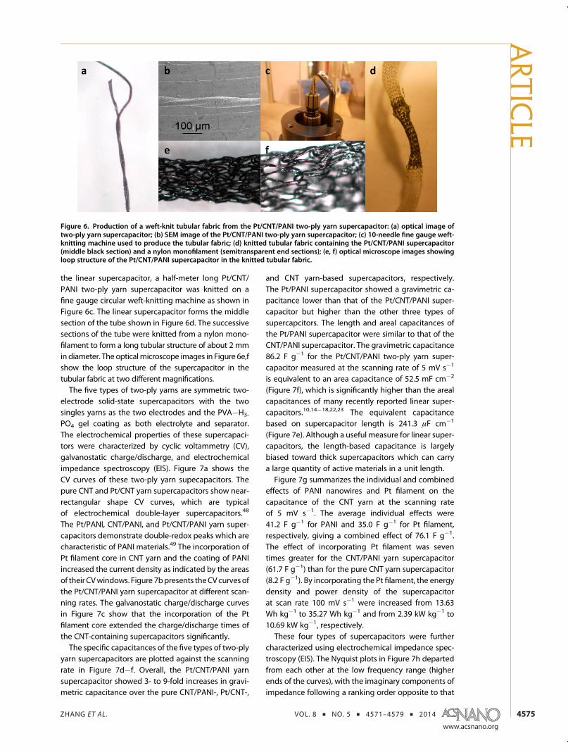
the linear supercapacitor, a half-meter long Pt/CNT/PANI two-ply yarn supercapacitor was knitted on afine gauge circular weft-knitting machine as shown inFigure 6c. The linear supercapacitor forms the middlesection of the tube shown in Figure 6d. The successivesections of the tube were knitted from a nylon mono-filament to form a long tubular structure of about 2 mmin diameter. The opticalmicroscope images in Figure 6e,fshow the loop structure of the supercapacitor in thetubular fabric at two different magnifications.The five types of two-ply yarns are symmetric two-
electrode solid-state supercapacitors with the twosingles yarns as the two electrodes and the PVA�H3-
PO4 gel coating as both electrolyte and separator.The electrochemical properties of these supercapaci-tors were characterized by cyclic voltammetry (CV),galvanostatic charge/discharge, and electrochemicalimpedance spectroscopy (EIS). Figure 7a shows theCV curves of these two-ply yarn supecapacitors. Thepure CNT and Pt/CNT yarn supercapacitors show near-rectangular shape CV curves, which are typicalof electrochemical double-layer supercapacitors.48
The Pt/PANI, CNT/PANI, and Pt/CNT/PANI yarn super-capacitors demonstrate double-redox peaks which arecharacteristic of PANI materials.49 The incorporation ofPt filament core in CNT yarn and the coating of PANIincreased the current density as indicated by the areasof their CVwindows. Figure 7bpresents theCV curvesofthe Pt/CNT/PANI yarn supercapacitor at different scan-ning rates. The galvanostatic charge/discharge curvesin Figure 7c show that the incorporation of the Ptfilament core extended the charge/discharge times ofthe CNT-containing supercapacitors significantly.The specific capacitances of the five types of two-ply
yarn supercapacitors are plotted against the scanningrate in Figure 7d�f. Overall, the Pt/CNT/PANI yarnsupercapacitor showed 3- to 9-fold increases in gravi-metric capacitance over the pure CNT/PANI-, Pt/CNT-,
and CNT yarn-based supercapacitors, respectively.The Pt/PANI supercapacitor showed a gravimetric ca-pacitance lower than that of the Pt/CNT/PANI super-capacitor but higher than the other three types ofsupercapcitors. The length and areal capacitances ofthe Pt/PANI supercapacitor were similar to that of theCNT/PANI supercapacitor. The gravimetric capacitance86.2 F g�1 for the Pt/CNT/PANI two-ply yarn super-capacitor measured at the scanning rate of 5 mV s�1
is equivalent to an area capacitance of 52.5 mF cm�2
(Figure 7f), which is significantly higher than the arealcapacitances of many recently reported linear super-capacitors.10,14�18,22,23 The equivalent capacitancebased on supercapacitor length is 241.3 μF cm�1
(Figure 7e). Although a useful measure for linear super-capacitors, the length-based capacitance is largelybiased toward thick supercapacitors which can carrya large quantity of active materials in a unit length.Figure 7g summarizes the individual and combined
effects of PANI nanowires and Pt filament on thecapacitance of the CNT yarn at the scanning rateof 5 mV s�1. The average individual effects were41.2 F g�1 for PANI and 35.0 F g�1 for Pt filament,respectively, giving a combined effect of 76.1 F g�1.The effect of incorporating Pt filament was seventimes greater for the CNT/PANI yarn supercapacitor(61.7 F g�1) than for the pure CNT yarn supercapacitor(8.2 F g�1). By incorporating the Pt filament, the energydensity and power density of the supercapacitorat scan rate 100 mV s�1 were increased from 13.63Wh kg�1 to 35.27 Wh kg�1 and from 2.39 kW kg�1 to10.69 kW kg�1, respectively.These four types of supercapacitors were further
characterized using electrochemical impedance spec-troscopy (EIS). The Nyquist plots in Figure 7h departedfrom each other at the low frequency range (higherends of the curves), with the imaginary components ofimpedance following a ranking order opposite to that
Figure 6. Production of a weft-knit tubular fabric from the Pt/CNT/PANI two-ply yarn supercapacitor: (a) optical image oftwo-ply yarn supercapacitor; (b) SEM image of the Pt/CNT/PANI two-ply yarn supercapacitor; (c) 10-needle fine gauge weft-knitting machine used to produce the tubular fabric; (d) knitted tubular fabric containing the Pt/CNT/PANI supercapacitor(middle black section) and a nylon monofilament (semitransparent end sections); (e, f) optical microscope images showingloop structure of the Pt/CNT/PANI supercapacitor in the knitted tubular fabric.
ARTIC
LE

ZHANG ET AL . VOL. 8 ’ NO. 5 ’ 4571–4579 ’ 2014
www.acsnano.org
4576
of the specific capacitances in Figure 7d. The inset inFigure 7h shows the impedances of the four super-capacitors at the high frequency range (lower endsof the curves). The x-intercept of the Nyquist plotrepresents the equivalent series resistance (ESR) thatcorresponds to charge transport resistance for two-electrode supercapacitor.10 The inset results show thatincorporating the Pt filament core has reduced theESR of the supercapacitors significantly. The Pt/CNT
yarn supercapacitor has a third of the ESR of the pureCNT yarn supercapacitor, and the Pt/CNT/PANI super-capacitor has a ESR that is 1 order ofmagnitude smallerthan that of the CNT/PANI yarn supercapacitor.Figure 8a shows the size effect of the CNT, CNT/PANI,
and Pt/CNT/PANI two-ply yarn supercapacitors. With-out the Pt filament core, the specific capacitances ofthe pure CNT and CNT/PANI supercapacitors diminishvery quickly with the increase of supercapacitor length.
Figure 7. Electrochemical properties of two-ply yarn supercapacitors: (a) cyclic voltammograms of the different types ofsupercapacitors at the same scanning rate of 100 mV s�1; (b) cyclic voltammograms of the Pt/CNT/PANI supercapacitor atdifferent scanning rates; (c) galvanostatic charge/discharge curves of the different types of supercapacitors; (d) gravimetriccapacitances of the different types of supercapacitors as a function of scanning rate; (e) length-based capacitances as afunction of scanning rate; (f) areal capacitances as a function of scanning rate; (g) effects of polyaniline nanowire depositionand Pt filament core on the gravimetric capacitance of the two-ply yarn supercapacitors; (h) electrochemical impedancespectra (0.01 Hz�500 kHz).
ARTIC
LE

ZHANG ET AL . VOL. 8 ’ NO. 5 ’ 4571–4579 ’ 2014
www.acsnano.org
4577
The capacitances of these two supercapacitors at100 mm length dropped to less than 20% of their basevalues at 10 mm. In comparison, the Pt/CNT/PANIsupercapacitor maintained 93% of its base capacitanceat 10 mm when its length was increased to 100 mm,and 51% when its length was further increased to320 mm. This means that the Pt/CNT/PANI two-plyyarn supercapacitor may be used as weft to producefoot-wide woven fabrics.Textile materials experience many cycles of bending
actions during fabrication and end use. The mostsevere form of bending action is repeated foldingand unfolding (flattening). As part of a wearableelectronic system, two-ply yarn supercapacitors mustmaintain their electrochemical performance after alarge number of folding�unfolding cycles. As shownin Figure 8b, the capacitance of the Pt/CNT/PANIsupercapacitor had little change after being subjectedto 1000 cycles of folding and unfolding.The above results suggest that the Pt/CNT core/
sheath yarn architecture played an important role inimproving the capacitance and up-scaling of the two-ply yarn supercapacitors. CNT yarns have a porousstructure which favors ionic motion and rate perfor-mance of electrodes.9 However, pure CNT yarns are nothighly conductive, with its electrical conductivity farbelowmetals. Charges generated on the active materi-als (PANI nanowires and the CNTs) in the electrodehave to cross a very large number of CNT-CNT bound-aries to be transported along the yarn length, resultingin low efficiency.7 With the incorporation of a metalfilament core, charges generated in the electrode onlyneed to cross a few CNT boundaries through the
thickness of the CNT sheath (2�3 μm) to reach thehighly conductive metal core. The metal filament coreserves as a super highway that collects the chargesgenerated at every position of the electrode andtransports them efficiently along the yarn length. TheCNT sheath provides a porous substrate withwhich thePANI nanowires can form an effective interface, as wellas provides the strength and flexibility to overcomefatigue of the high performance PANI polymer causedby repeated mechanical bending and due to swellingand shrinking during cyclic charge and discharge.
CONCLUSION
We have reported a new carbon nanotube yarnstructure and its suitability for application in linearsupercapacitors. The new yarn consists of a high con-ductivity metal filament coaxially embedded in a layerof carbon nanotubes and can be manufactured by acontinuous core yarn spinning method. The strongand flexible core/sheath structured yarn can be pliedtogether to form a two-ply yarn supercapacitor on itsown or used as substrate for high performance pseu-docapacitance materials. In the two-ply yarn super-capacitors, the metal filament core serves as currentcollector to provide a super highway for transportationof charges generated along the length of two-ply yarnsupercapacitor, leading to significant increases in en-ergy andpower storage capacities. The newarchitectureenables the lengthof the supercapacitor to beup-scaleddramatically. Tensile test, flexing test, and machineknitting trial show that the two-ply yarn supercapacitoris highly flexible and robust as high performance powersource for wearable electronic devices.
METHODS
Production of As-Spun Carbon Nanotube Yarns. CNT forests weregrown on silicon wafer substrates bearing a thermal oxidelayer and iron catalyst coating using chemical vapor deposition(CVD) of acetylene in helium. The synthesis procedures hadbeen optimized as reported previously.42 The resulting CNTshad 7 ( 2 walls with an outer diameter of 10 nm and an inner
diameter of approximately 4 nm. The length of the CNTs wasapproximately 350 μm by measuring the height of the forests.
The core/sheath Pt/CNT yarn ismanufactured using the flyer-spinner shown in Figure 1.35 The CNT yarns were spun to a twistlevel of 5000 turns per meter using a spindle speed of 5000 rpm.
Preparation of Polyaniline Nanowire Solution. Polyaniline nano-wires were synthesized using a reported procedure47with some
Figure 8. Capacitance retention: (a) size effects on different supercapacitors at a constant scanning rate 500mV s�1; (b) effectof repeated folding-unfolding actions on the capacitance of Pt/CNT/PANI two-ply yarn supercapacitor.
ARTIC
LE

ZHANG ET AL . VOL. 8 ’ NO. 5 ’ 4571–4579 ’ 2014
www.acsnano.org
4578
minor modifications. Aniline and potassium biiodate (KH(IO3)),were dissolved at concentrations of 0.1 and 0.0125M in 1MHCl,respectively. Aniline solution (36 mL), 40 mL of KH(IO3) solution,and 1 mL of sodium hypochlorite solution (wt 5%, NaClO) weremixed and kept undisturbed at room temperature for 2.5 h.The resulting solution was centrifuged, followed by removingthe supernatant. HCl (1 M) solutions were added to redissolvethe synthesized PANI. After three cycles of centrifugation, thePANI nanowire solution was obtained.
Preparation of PVA�H3PO4 Gel. Hydrolyzed poly(vinyl alcohol)(PVA) (98�99%) with average molecular weight of 57000�66000 was supplied by Alfa Aesar. H3PO4 (0.8 g) (analyticalgrade) was added to 10 mL of deionized water with vigorousstirring, and then 1 g of PVA powder was added. The solutionwas heated steadily to 90 �C under vigorous stirring until thesolution became clear to form the PVA�H3PO4 gel.
Preparation of Two-Ply Yarn Supercapacitors. Coating of PANI andPVA�H3PO4 gel was carried out using a home-built continuouscoating line, displayed as Figure S1 in the Supporting Informa-tion. The coating line includes a pigtail-shaped reservoir forholding liquid, an electrical heating unit for drying, and anelectrical motor for controlling yarn throughput speed. Theliquid take-up rate and uniformity are controlled by adjustingthe motor speed. Large adjustments of liquid take-up rate canbe achieved by varying the viscosity of the polymer solution.
Two identical yarns were twisted together to form a two-ply yarn supercapacitor using the twisting device shown inFigure S2 (Supporting Information).
Focused Ion Beam Milling. An FEI high-resolution dual-beamHelios 600 focused ion beam (FIB) equipped with a SEM wasused to form cross-sections through the CNT yarns and to takeyarn cross-sectional images. The electron and ion beams inter-sect at a 52� angle at a coincident point near the sample surface,allowing immediate SEM imaging of the FIB-milled surface.Initially, the milling was performed with a 31 nA, 30 kV Galliumbeam. The CNT sheath in the cross-section was covered byredeposition of platinum sputtering due to the high beamcurrent. To obtained a clear image of the core/sheath yarncross-section, a sectional surface prepared by high beam cur-rent was further treated by “polish milling” using a low beamcurrent (2 nA). This gave a clear sectional view of the core/sheath structure.
Measurement of Linear Density. Linear density in tex (1 tex =1 mg/m = 1 μg/mm) was determined by weighing a 100 mmlength of the linear material (platinum filament, as-spun CNTyarn, Pt/CNT yarn or their coated yarns) on a high-sensitivityMettler Toledo Xp2U Ultra Micro Balance. The linear densityvalues were then used to calculate mass ratios of the constitu-ent parts in the resultant yarns.
Tensile Testing. Yarn tensile tests were conducted using aChatillon tensile testing machine equipped with a laser diffrac-tion system for yarn diameter measurement as describedpreviously.50 Each specimen was attached to a paper handlingframe using PVA adhesive. The testing gauge lengthwas 10mm.At least five specimens from each sample were tested and theaverage results were reported.
Strength of Pt/CNT Interface. A 3-pin device as shown inFigure S1 (Supporting Information) was constructed to testthe robustness of the sheath/core interface of the Pt/CNT corespun yarn under cyclic bending and rubbing actions. One endofthe yarn is tied to the fixed pin 1 and the other end is tied toa weight to provide a tension of 10 cN/tex based on the CNTsheath. When the latch needle moves up and down, the yarn isrubbed against the other three fixed pins 2, 3, and 4. Two rubsare applied to the yarn sample as the needlemoves one up-and-down cycle. The CNT/Pt core spun yarns were tested for up to60 cycles (120 rubbing actions). The rubbed areas of the yarnwere then examined in SEM.
Electrical Conductivity. Electrical conductivity of CNT yarnswere measured using a four-probe method.37 The electricalresistances of CNT yarn specimens were measured at a fixedspan length of 50 mm. A constant tension was applied to theyarn specimen during the measurement by hanging a mass oneach end of the specimen.
Electrochemical Characterization. Cyclic voltammetry (CV), gal-vanostatic charge/discharge, and electrochemical impedancespectroscopy (EIS) were performed on a bipotentiostat electro-chemical workstation (700D, CH Instruments) using a two-electrode configuration. Short length supercapacitors (10�50 mm)were mounted on a paper frame and connected to the instru-ment for measurement. Long supercapacitors (up to 380 mm)were wrapped on a tube with two ends mounted on a paperframe connector, as shown in Figure S3 (Supporting Information).Gravimetric capacitances of the supercapacitors were derivedusing the formula
C ¼ 1wv(Vc � Va)
Z Vc
Va
I(V)dV (1)
where C is specific capacitance (F g�1), w is the mass of activeconstituents in the working electrode (g), v is the scanning rate(V/S), Vc � Va is the potential window (V), and I(V) is the currentdensity. The mass of the active constituents (CNT and PANI) wascalculated by subtracting the linear density of the platinumfilament from the linear density of the Pt/CNT/PANI yarn. Specificareal capacitance was calculated by replacing w in the aboveequation with the surface area of the working electrode A (cm2):A = πdl, where d is the yarn diameter in cm and l is the length ofthe electrode in cm.
Nitrogen Adsorption�Desorption Experiments. N2 adsorption�desorption experiments were conducted at �196 �C with aQuantachrome Autosorb-1-C-MS. The mesopore size distribu-tions were obtained from the desorption branches of theisotherms using the Barrett�Joyner�Halenda (BJH) method.
Conflict of Interest: The authors declare no competingfinancial interest.
Supporting Information Available: Photographic images ofpreparation and testing equipment; video of core�sheath yarnspinning. Thismaterial is available free of charge via the Internetat http://pubs.acs.org.
Acknowledgment. We thank the following colleagues fortheir assistance: A. van de Meene, Melbourne Centre for Nano-fabrication, and C. P. Huynh, P. Hewitt, M. Pate, and C. Veitch,CSIRO Materials Science and Engineering. D.Z. acknowledgesthe China Scholarship Council for granting a visiting scholarshipthat enabled him to carry out this work at CSIRO in Australia.
REFERENCES AND NOTES1. Zhi, M.; Xiang, C.; Li, J.; Li, M.; Wu, N. Nanostructured
Carbon�Metal Oxide Composite Electrodes for Superca-pacitors: A Review. Nanoscale 2013, 5, 72–88.
2. Cai, X.; Peng, M.; Yu, X.; Fu, Y.; Zou, D. Flexible Planar/Fiber-Architectured Supercapacitors for Wearable Energy Storage.J. Mater. Chem. C 2014, 2), 1184–1200.
3. Jost, K.; Dion, G.; Gogotsi, Y. Textile Energy Storage inPerspective. J. Mater. Chem. A 2014, 10.1039/C4TA00203B.
4. Nguyen, T. H.; Fraiwan, A.; Choi, S. Paper-Based Batteries:A Review. Biosens. Bioelectron. 2014, 54, 640–649.
5. Jost, K.; Stenger, D.; Perez, C. R.; McDonough, J. K.; Lian, K.;Gogotsi, Y.; Dion, G. Knitted and Screen Printed Carbon-Fiber Supercapacitors for Applications in Wearable Elec-tronics. Energy Environ. Sci. 2013, 6, 2698–2705.
6. Dai, L.; Chang, D.W.; Baek, J.-B.; Lu,W. CarbonNanomaterialsfor Advanced Energy Conversion and Storage. Small 2012,8, 1130–1166.
7. Ren, J.; Li, L.; Chen, C.; Chen, X.; Cai, Z.; Qiu, L.; Wang, Y.; Zhu,X.; Peng, H. Twisting Carbon Nanotube Fibers for BothWire-Shaped Micro-Supercapacitor and Micro-Battery.Adv. Mater. 2013, 25, 1155–1159.
8. Hu, L.; Wu, H.; La Mantia, F.; Yang, Y.; Cui, Y. Thin, FlexibleSecondary Li-Ion Paper Batteries. ACS Nano 2010, 4, 5843–5848.
9. Zhang, H.; Cao, G.; Wang, Z.; Yang, Y.; Shi, Z.; Gu, Z. Tube-Covering-Tube Nanostructured Polyaniline/Carbon Nano-tube Array Composite Electrode with High Capacitanceand Superior Rate Performance as Well as Good CyclingStability. Electrochem. Commun. 2008, 10, 1056–1059.
ARTIC
LE

ZHANG ET AL . VOL. 8 ’ NO. 5 ’ 4571–4579 ’ 2014
www.acsnano.org
4579
10. Wang, K.; Meng, Q.; Zhang, Y.; Wei, Z.; Miao, M. High-Performance Two-Ply Yarn Supercapacitors Based onCarbon Nanotubes and Polyaniline Nanowire Arrays.Adv. Mater. 2013, 25, 1494–1498.
11. Lee, J. A.; Shin, M. K.; Kim, S. H.; Cho, H. U.; Spinks, G. M.;Wallace, G. G.; Lima, M. D.; Lepró, X.; Kozlov, M. E.; Baugh-man, R. H.; et al. Ultrafast Charge and Discharge BiscrolledYarn Supercapacitors for Textiles and Microdevices. Nat.Commun. 2013, 4, 1970.
12. Su, F.; Miao, M. Asymmetric Carbon Nanotube�MnO2
Two-Ply Yarn Supercapacitors for Wearable Electronics.Nanotechnology 2014, 25, 135401.
13. Su, F.; Miao, M. Flexible, High Performance Two-Ply YarnSupercapacitors Based on Irradiated Carbon NanotubeYarn and PEDOT/PSS. Electrochim. Acta 2014, 127, 433–438.
14. Fu, Y.; Cai, X.; Wu, H.; Lv, Z.; Hou, S.; Peng, M.; Yu, X.; Zou, D.Fiber Supercapacitors Utilizing Pen Ink for Flexible/Wearable Energy Storage.Adv.Mater.2012, 24, 5713–5718.
15. Li, Y.; Sheng, K.; Yuan, W.; Shi, G.; High-Performance, A.Flexible Fibre-Shaped Electrochemical Capacitor Basedon Electrochemically Reduced Graphene Oxide. Chem.Commun. 2013, 49, 291–293.
16. Harrison, D.; Qiu, F.; Fyson, J.; Xu, Y.; Evans, P.; Southee, D.A Coaxial Single Fibre Supercapacitor for Energy Storage.Phys. Chem. Chem. Phys. 2013, 15, 12215–12219.
17. Bae, J.; Song, M. K.; Park, Y. J.; Kim, J. M.; Liu, M.; Wang, Z. L.Fiber Supercapacitors Made of Nanowire-Fiber HybridStructures for Wearable/Flexible Energy Storage. Angew.Chem., Int. Ed. 2011, 50, 1683–1687.
18. Yang, Z.; Deng, J.; Chen, X.; Ren, J.; Peng, H. A HighlyStretchable, Fiber-Shaped Supercapacitor. Angew. Chem.,Int. Ed. 2013, 52, 13453–13457.
19. Le, V. T.; Kim, H.; Ghosh, A.; Kim, J.; Chang, J.; Vu, Q. A.;Pham, D. T.; Lee, J.-H.; Kim, S.-W.; Lee, Y. H. Coaxial FiberSupercapacitor Using All-Carbon Material Electrodes. ACSNano 2013, 7, 5940–5947.
20. Foroughi, J.; Spinks, G. M.; Ghorbani, S. R.; Kozlov, M. E.;Safaei, F.; Peleckis, G.; Wallace, G. G.; Baughman, R. H.Preparation and Characterization of Hybrid ConductingPolymer-Carbon Nanotube Yarn. Nanoscale 2012, 4, 940–945.
21. Cai, Z.; Li, L.; Ren, J.; Qiu, L.; Lin, H.; Peng, H. Flexible,Weavable and Efficient Microsupercapacitor Wires Basedon Polyaniline Composite Fibers Incorporated withAligned Carbon Nanotubes. J. Mater. Chem. A 2013, 1,258–261.
22. Chen, X.; Qiu, L.; Ren, J.; Guan, G.; Lin, H.; Zhang, Z.; Chen, P.;Wang, Y.; Peng, H. Novel Electric Double-Layer Capacitorwith a Coaxial Fiber Structure. Adv. Mater. 2013, 25, 6436–6441.
23. Xu, P.; Gu, T.; Cao, Z.; Wei, B.; Yu, J.; Li, F.; Byun, J.-H.; Lu, W.;Li, Q.; Chou, T.-W. Carbon Nanotube Fiber Based Stretch-able Wire-Shaped Supercapacitors. Adv. Energy Mater.2014, 4, 1300759.
24. Ren, J.; Bai, W.; Guan, G.; Zhang, Y.; Peng, H. Flexible andWeaveable Capacitor Wire Based on a Carbon Nanocom-posite Fiber. Adv. Mater. 2013, 25, 5965–5970.
25. Meng, Y.; Zhao, Y.; Hu, C.; Cheng, H.; Hu, Y.; Zhang, Z.; Shi,G.; Qu, L. All-Graphene Core-Sheath Microfibers for All-Solid-State, Stretchable Fibriform Supercapacitors andWearable Electronic Textiles. Adv. Mater. 2013, 25, 2326–2331.
26. Cheng, H.; Dong, Z.; Hu, C.; Zhao, Y.; Hu, Y.; Qu, L.; Chen, N.;Dai, L. Textile Electrodes Woven by Carbon Nanotube-Graphene Hybrid Fibers for Flexible ElectrochemicalCapacitors. Nanoscale 2013, 5, 3428–3434.
27. Xu, J.; Wang, K.; Zu, S.-Z.; Han, B.-H.; Wei, Z. HierarchicalNanocomposites of Polyaniline Nanowire Arrays onGraphene Oxide Sheets with Synergistic Effect for EnergyStorage. ACS Nano 2010, 4, 5019–5026.
28. He, G.; Chen, H.; Zhu, J.; Bei, F.; Sun, X.; Wang, X. Synthesisand Characterization of Graphene Paper with ControllableProperties via Chemical Reduction. J. Mater. Chem. 2011,21, 14631–14638.
29. Wang, K.; Zou, W.; Quan, B.; Yu, A.; Wu, H.; Jiang, P.; Wei, Z.AnAll-Solid-State FlexibleMicro-Supercapacitor on a Chip.Adv. Energy Mater. 2011, 1, 1068–1072.
30. Wang, K.; Wu, H.; Meng, Y.; Zhang, Y.; Wei, Z. IntegratedEnergy Storage and Electrochromic Function in OneFlexible Device: An Energy Storage Smart Window. EnergyEnviron. Sci. 2012, 5, 8384–8389.
31. Wang, K.; Huang, J.; Wei, Z. Conducting Polyaniline Nano-wire Arrays for High Performance Supercapacitors. J. Phys.Chem. C 2010, 114, 8062–8067.
32. Masarapu, C.; Zeng, H. F.; Hung, K. H.; Wei, B. Effect ofTemperature on the Capacitance of Carbon NanotubeSupercapacitors. ACS Nano 2009, 3, 2199–2206.
33. Dai, L.; Chang, D. W.; Baek, J. B.; Lu, W. Carbon Nanomater-ials for Advanced Energy Conversion and Storage. Small2012, 8, 1130–1166.
34. Fan, Z.; Yan, J.; Zhi, L.; Zhang, Q.; Wei, T.; Feng, J.; Zhang, M.;Qian, W.; Wei, F.; Three-Dimensional, A. Carbon Nanotube/Graphene Sandwich and Its Application as Electrode inSupercapacitors. Adv. Mater. 2010, 22, 3723–3728.
35. Miao, M. Yarn Spun from Carbon Nanotube Forests:Production, Structure, Properties and Applications.Particuology 2013, 11, 378–393.
36. Fan, L. Z.; Hu, Y. S.; Maier, J.; Adelhelm, P.; Smarsly, B.;Antonietti, M. High Electroactivity of Polyaniline in Super-capacitors by Using a Hierarchically Porous CarbonMonolithas a Support. Adv. Funct. Mater. 2007, 17, 3083–3087.
37. Miao, M. Electrical Conductivity of Pure Carbon NanotubeYarns. Carbon 2011, 49, 3755–3761.
38. Ouyang, J.; Chu, C. W.; Chen, F. C.; Xu, Q.; Yang, Y. High-ConductivityPoly(3,4-ethylenedioxythiophene):Poly(styrenesulfonate) Filmand Its Application inPolymerOptoelectronicDevices. Adv. Funct. Mater. 2005, 15, 203–208.
39. Choi, K. S.; Liu, F.; Choi, J. S.; Seo, T. S. Fabrication of Free-Standing Multilayered Graphene and Poly(3,4-ethylenedi-oxythiophene) Composite Films with Enhanced Conduc-tive and Mechanical Properties. Langmuir 2010, 26,12902–12908.
40. Lang, U.; Naujoks, N.; Dual, J. Mechanical Characterizationof PEDOT:PSS Thin Films. Synth. Met. 2009, 159, 473–479.
41. Niu, Z.; Zhou,W.; Chen, J.; Feng, G.; Li, H.; Ma,W.; Li, J.; Dong,H.; Ren, Y.; Zhao, D.; et al. Compact-Designed Super-capacitors Using Free-Standing Single-Walled CarbonNanotube Films. Energy Environ. Sci. 2011, 4, 1440–1446.
42. Huynh, C. P.; Hawkins, S. C. Understanding the Synthesisof Directly Spinnable Carbon Nanotube Forests. Carbon2010, 48, 1105–1115.
43. Miao, M.; Chen, R. Yarn Twisting Dynamics. Text. Res. J.1993, 63, 150–158.
44. Miao,M.; Barnes, S.; Vuckovic, L. High-Speed VideoGraphicStudy of Filament-Core Yarn Spinning. J. Text. Inst. 2009,101, 242–252.
45. Miao, M.; How, Y.-L.; Ho, S.-Y. Influence of Spinning Param-eters on Core Yarn Sheath Slippage and Other Properties.Text. Res. J. 1996, 66, 676–684.
46. Uster Technologies AG: Uster Statistics - Fibre and YarnQuality. http://www.uster.com/en/service/uster-statistics/(accessed April 24, 2014).
47. Rahy, A.; Yang, D. J. Synthesis of Highly Conductive Poly-aniline Nanofibers. Mater. Lett. 2008, 62, 4311–4314.
48. Zhai, Y.; Dou, Y.; Zhao, D.; Fulvio, P. F.; Mayes, R. T.; Dai, S.Carbon Materials for Chemical Capacitive Energy Storage.Adv. Mater. 2011, 23, 4828–4850.
49. Rudge, A.; Davey, J.; Raistrick, I.; Gottesfeld, S.; Ferraris, J. P.Conducting Polymers as ActiveMaterials in ElectrochemicalCapacitors. J. Power Sources 1994, 47, 89–107.
50. Miao,M.;McDonnell, J.; Vuckovic, L.; Hawkins, S. C. Poisson'sRatio and Porosity of Carbon Nanotube Dry-Spun Yarns.Carbon 2010, 48, 2802–2811.
ARTIC
LE