Embed Size (px)
Citation preview

Cordless Drill12V Li-IonInstruction Manual3 Year Replacement Warranty
LIR-012WARNING: Read all safety warnings and all instructions. Failure to follow the
warnings and instructions may result in electric shock, fire and /or serious injury.Save all warnings and instructions for future reference.
To view the full range visit: www.ozito.com.au0912
!
Motor: 12V Charge time: 3 – 5 hoursNo load speed: 0 – 350/min, 0 – 1150/minChuck: 10mm KeylessTorque: 15NmBatteries: 2 x 1.3Ah Lithium IonWeight with 1 battery: 1.05kg
1. Keyless chuck2. Torque adjustment collar3. Speed selector4. Forward/reverse selector5. Battery 6. Battery release buttons
7. Variable speed switch 8. LED light 9. Charging adaptor 10. Charging cradle 11. Charger jack
2
56
1
8
3
4
9 10
7
11
SPECIFICATIONS – MODEL NO. LIR-012
1
KNOW YOUR PRODUCT
2
TABLE OF CONTENTS
SPECIFICATIONS ………………………………………..
INTRODUCTION…………………………………………
ELECTRICAL SAFETY……………………………………
GENERAL POWER TOOL SAFETY WARNINGS….….
BATTERY & CHARGER SAFETY FEATURE……………
CHARGING THE BATTERY……………………………..
INSTALLING OR REMOVING THE BATTERY...………
DRILL OPERATION………………………………………
MAINTENANCE …………….…………………………..
SPARE PARTS …………….……………………………...
DESCRIPTION OF SYMBOLS ………………………….
CONTENTS ……………………………………………...
WARRANTY………………………………………………
Page 1
Page 3
Page 3
Page 4
Page 6
Page 7
Page 8
Page 9
Page 12
Page 12
Page 13
Page 14
Page 15
!
!
INTRODUCTION
3
THIS MANUAL CONTAINS IMPORTANT SAFETY AND OPERATINGINSTRUCTIONS FOR YOUR BATTERY CHARGER.
• Before using the charger, read all instructions and cautionary markings oncharger, battery pack and product using the battery pack.
Danger! If the battery pack case is cracked or damaged, do not insertinto charger. There is a danger of electric shock or electrocution.
Warning! Don’t allow any liquid to get inside charger. Electric shock mayresult. To facilitate cooling of the battery pack after use, avoid placing thecharger or battery pack in a warm environment such as in a metal shed, oran uninsulated trailer.
• This charger is not intended for any uses other than charging rechargeablebatteries. Any other use may result in risk of fire, electric shock or electrocution.
• Do not place any object on top of the charger or place the charger on a softsurface that may result in excessive internal heat. Place the charger in aposition away from any heat source.
• To reduce risk of damage to the electric plug and cord, pull by the plug ratherthan the cord when disconnecting the charger.
• Make sure cord is located so that it will not be stepped on, tripped over, orotherwise subjected to damage or stress.
• An extension cord should not be used unless absolutely necessary. Use of animproper extension cord could result in the risk of fire, electric shock or electrocution.
• Do not operate charger if it has received a sharp blow, been dropped orotherwise damaged in any way. Have it checked by an electrician or power tool repairer.
• Do not disassemble charger. Take it to an electrician or power tool repairerwhen service or repair is required. Incorrect reassembling may result in a risk ofelectric shock, electrocution or fire.
• To reduce risk of electric shock, unplug charger from the outlet beforeattempting any cleaning. Removing the battery pack will not reduce this risk.
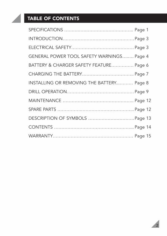
Congratulations on purchasing an Ozito Lithium Ion CordlessDrill. We aim to provide quality tools at an affordable price.
We hope you will enjoy using this tool for many years. YourLithium Ion Cordless Drill LIR-012 has been designed forgeneral purpose drilling or screwdriving around the homeand is intended for DIY use only.
ELECTRICAL SAFETY!
4
ELECTRICAL SAFETY (cont.)!
• Never attempt to connect 2 chargers together.
• DO NOT store or use the tool and battery pack in locations where thetemperature may reach or exceed 40ºC (such as outside sheds or metal buildingsin summer).
• The charger is designed to operate on standard household electrical power (240 volts).Do not attempt to use it on any other voltage!
The battery pack is not fully charged out of the carton. First read the safetyinstructions and then follow the charging notes and procedures.
• The longest life and best performance can be obtained if the battery pack ischarged when the air temperature is between 18 - 24ºC. Do not charge thebattery pack in an air temperature below 10ºC or above 40ºC. This is importantand will prevent damage to the battery pack.
• Do not incinerate the battery pack even if it is seriously damaged or is completelyworn out. The battery can explode in a fire.
• Never attempt to open the battery pack for any reason. If the plastic housing of thebattery pack breaks or cracks, immediately discontinue use and do not recharge.
Warning! Read all safety warnings and all instructions. Failure to follow thewarnings and instructions may result in electric shock, fire and/or serious injury.
Save all warnings and instructions for future reference.The term "power tool" in all of the warnings refers to your mains-operated(corded) power tool or battery-operated (cordless) power tool.
1) Work area safety
a) Keep work area clean and well lit. Cluttered and dark areas invite accidents. b) Do not operate power tools in explosive atmospheres, such as in the
presence of flammable liquids, gases or dust. Power tools create sparks whichmay ignite the dust or fumes.
c) Keep children and bystanders away while operating a power tool. Distractionscan cause you to lose control.
2) Electrical safety
a) Power tool plugs must match the outlet. Never modify the plug in any way.Do not use any adapter plugs with earthed (grounded) power tools.Unmodified plugs and matching outlets will reduce risk of electric shock
b) Avoid body contact with earthed or grounded surfaces such as pipes,radiators, ranges and refrigerators. There is an increased risk of electric shock ifyour body is earthed or grounded.
c) Do not expose power tools to rain or wet conditions. Water entering a powertool will increase the risk of electric shock.
d) Do not abuse the cord. Never use the cord for carrying, pulling or unpluggingthe power tool. Keep cord away from heat, oil, sharp edges or moving parts.Damaged or entangled cords increase the risk of electric shock.
!
General Power Tool Safety Warnings - Personal Safety!
5
e) When operating a power tool outdoors, use an extension cord suitable foroutdoor use. Use of a cord suitable for outdoor use reduces the risk of electric shock.
3) Personal safety
a) Stay alert, watch what you are doing and use common sense whenoperating a power tool. Do not use a power tool while you are tired orunder the influence of drugs, alcohol or medication. A moment ofinattention while operating power tools may result in serious personal injury.
b) Use personal protective equipment. Always wear eye protection.Protective equipment such as dust mask, non-skid safety shoes, hard hat, orhearing protection used for appropriate conditions will reduce personal injuries.
c) Prevent unintentional starting. Ensure the switch is in the off-positionbefore connecting to power source and/or battery pack, picking up orcarrying the tool. Carrying power tools with your finger on the switch orenergising power tools that have the switch on invites accidents.
d) Remove any adjusting key or wrench before turning the power tool on. Awrench or a key left attached to a rotating part of the power tool may result inpersonal injury.
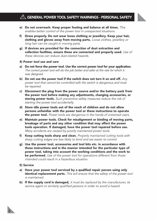
e) Do not overreach. Keep proper footing and balance at all times. Thisenables better control of the power tool in unexpected situations.
f) Dress properly. Do not wear loose clothing or jewellery. Keep your hair,clothing and gloves away from moving parts. Loose clothes, jewellery orlong hair can be caught in moving parts.
g) If devices are provided for the connection of dust extraction and collectionfacilities, ensure these are connected and properly used. Use of thesedevices can reduce dust-related hazards.
4) Power tool use and care
a) Do not force the power tool. Use the correct power tool for your application.The correct power tool will do the job better and safer at the rate for which it was designed.
b) Do not use the power tool if the switch does not turn it on and off. Anypower tool that cannot be controlled with the switch is dangerous and must be repaired.
c) Disconnect the plug from the power source and/or the battery pack fromthe power tool before making any adjustments, changing accessories, orstoring power tools. Such preventive safety measures reduce the risk ofstarting the power tool accidentally.
d) Store idle power tools out of the reach of children and do not allowpersons unfamiliar with the power tool or these instructions to operatethe power tool. Power tools are dangerous in the hands of untrained users.
e) Maintain power tools. Check for misalignment or binding of moving parts,breakage of parts and any other condition that may affect the power toolsoperation. If damaged, have the power tool repaired before use. Manyaccidents are caused by poorly maintained power tools.
General Power Tool Safety Warnings - Personal Safety!
General Power Tool Safety Warnings - Personal Safety
6
LITHIUM ION BATTERY AND CHARGER SAFETY FEATURES
!
f) Keep cutting tools sharp and clean. Properly maintained cutting tools with sharpcutting edges are less likely to bind and are easier to control.
g) Use the power tool, accessories and tool bits etc. in accordance with theseinstructions and in the manner intended for the particular type of power tool,taking into account the working conditions and the work to be performed.Use of the power tool for operations different from those intended could result ina hazardous situation.
5) Service
a) Have your power tool serviced by a qualified repair person using onlyidentical replacement parts. This will ensure that the safety of the power tool ismaintained.
b) If the supply cord is damaged, it must be replaced by the manufacturer, itsservice agent or similarly qualified persons in order to avoid a hazard.
Over Charging Protection
This feature ensures that the battery is never overcharged. When the battery hasreached it’s full charge capacity the charger will shut off protecting the internalcomponents of the battery from being damaged.
Over Discharge Protection
An internal component of the battery pack is an over discharge protector. This featurewill stop the battery from discharging beyond the recommended lowest safety voltage.
Over Heat Protection
The battery has an internal Thermister cut off sensor which will cease the chargingcycle if the battery becomes hot during the charging process. This Thermister sensorwill also stop the battery from operating should the battery become too hot duringthe operation of the tool. This can happen when the tool is overloaded or being usedfor extended periods of time .
Up to 30min in cooling time may be required depending on ambient temperature andoperation being performed.
Over Current Protection
Should the battery be overloaded and the maximum current draw be exceeded thebattery will temporarily stop working to protect the internal components. The batterywill resume to normal operation once the excessive current draw has returned tonormal safe level. This may take a few seconds.
Short Circuit Protection
If the battery pack was to short circuit the short circuit protector would immediatelystop the battery pack from operating.
This will ensure that no further internal components of the battery or the tools aredamaged.

7
The drill has been shipped in a low charge condition, andrequires charging prior to use.• Insert the charging adaptor (9) into the charging cradle (10)
(see Fig. 1). Plug the charger adaptor (9) into a 240V poweroutlet. Ensure that the charging cradle (10) is on a flat surface.
• Insert the battery (5) into the charging cradle (10). Therecess of the battery terminals will have a firm connection.Upon proper contact the red and green light will illuminateon the charging cradle (11).
• The battery (5) will take 3 – 5 hours to charge. Chargingstarts automatically. Remove the battery (5) from thecharger after 5 hours.
NOTE: If light on the charging cradle (10) fails to come on.• Check the charging adaptor (9) is securely plugged into the wall outlet and is
switched on.• Check the battery (5) is firmly seated onto the charging cradle (10).• Check the charging jack (11) is securely connected into the charging cradle (10) socket.
Initial Charge
• When the unit is on charge the red and green light will be on display. • The green light will appear only when the battery is fully charged. • Charge your battery for 3 – 5 hours then use it until it runs down and only
slowly operates.• Repeat this charge and discharge process approximately 4-5 times, this will
ensure that the battery is performing to its highest capacity.
Important Charging Notes
• The charger and battery (5) may become warm to touch while charging. This isa normal condition, and does not indicate a problem.
• Use the charger at normal room temperature whenever possible. To preventoverheating, do not cover the charger and do not charge the battery (5) indirect sunlight or near heat sources.
• If the battery (5) does not charge properly:-1. Check current at power outlet by plugging in a lamp or other appliance.2. If charging problems persist, have the complete drill checked by an
electrician or a power tool repairer.
NOTE: If battery is flat and displays green charged LED, refer to Thermal voltageprotection note below cooling maybe required.
Thermal voltage protection indication
In the event that the thermal or voltage protection circuit has been activated thebattery will cease to operate. This can happen when the tool has been used forextended periods or worked hard with large drill bits or accessories.If you place the battery on the charger the LED lights will give you the appearance thatthe battery is fully charged. Leave the battery on the charger to charge for 3-5 hours. The battery may take the full 5 hours to charge as the battery may need to cooldown or the protection circuit to be reset. This will then allow the charger to begincharging the battery and resume normal operation.
CHARGING YOUR LITHIUM ION BATTERY
Fig. 1
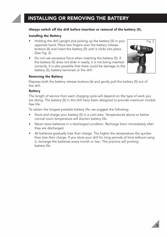
Always switch off the drill before insertion or removal of the battery (5).
Installing the Battery
• Holding the drill upright and picking up the battery (5) in youropposite hand. Place two fingers over the battery releasebuttons (6) and insert the battery (5) until it clicks into place(See Fig. 2).
• Do not use excessive force when inserting the battery (5). Ifthe battery (5) does not slide in easily, it is not being insertedcorrectly. It is also possible that there could be damage to thebattery (5), battery terminals or the drill.
Removing the Battery
Depress both the battery release buttons (6) and gently pull the battery (5) out of the drill.
Battery
The length of service from each charging cycle will depend on the type of work youare doing. The battery (5) in this drill have been designed to provide maximum troublefree life.
To obtain the longest possible battery life, we suggest the following:
• Store and charge your battery (5) in a cool area. Temperatures above or belownormal room temperature will shorten battery life.
• Never store batteries in a discharged condition. Recharge them immediately afterthey are discharged.
• All batteries gradually lose their charge. The higher the temperature the quickerthey lose their charge. If you store your drill for long periods of time without usingit, recharge the batteries every month or two. This practice will prolong battery life.
8
INSTALLING OR REMOVING THE BATTERY
Fig. 2
9
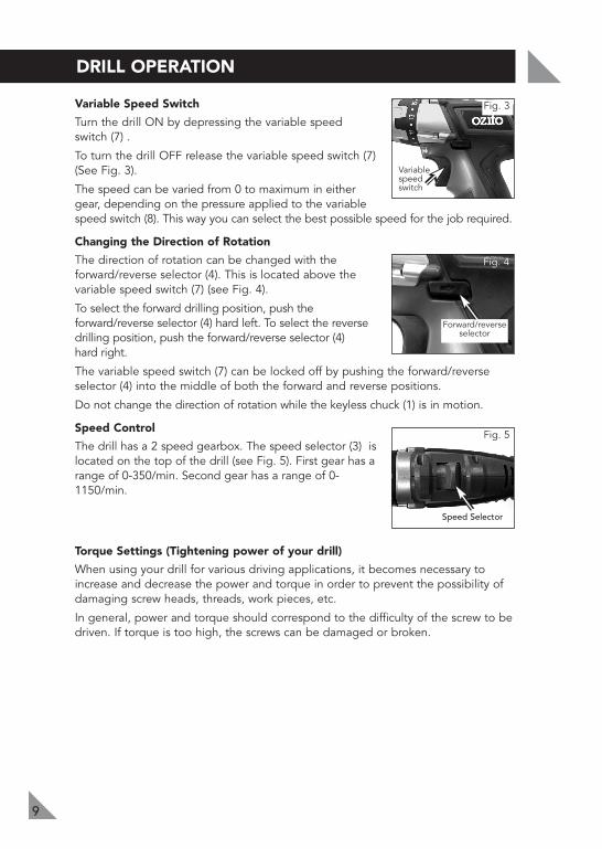
Variable Speed Switch
Turn the drill ON by depressing the variable speed switch (7) .
To turn the drill OFF release the variable speed switch (7)(See Fig. 3).
The speed can be varied from 0 to maximum in eithergear, depending on the pressure applied to the variablespeed switch (8). This way you can select the best possible speed for the job required.
Changing the Direction of Rotation
The direction of rotation can be changed with theforward/reverse selector (4). This is located above thevariable speed switch (7) (see Fig. 4).
To select the forward drilling position, push theforward/reverse selector (4) hard left. To select the reversedrilling position, push the forward/reverse selector (4) hard right.
The variable speed switch (7) can be locked off by pushing the forward/reverseselector (4) into the middle of both the forward and reverse positions.
Do not change the direction of rotation while the keyless chuck (1) is in motion.
Speed Control
The drill has a 2 speed gearbox. The speed selector (3) islocated on the top of the drill (see Fig. 5). First gear has arange of 0-350/min. Second gear has a range of 0-1150/min.
Torque Settings (Tightening power of your drill)
When using your drill for various driving applications, it becomes necessary toincrease and decrease the power and torque in order to prevent the possibility ofdamaging screw heads, threads, work pieces, etc.
In general, power and torque should correspond to the difficulty of the screw to bedriven. If torque is too high, the screws can be damaged or broken.
DRILL OPERATION
Fig. 3
Variablespeedswitch
Fig. 4
Fig. 5
Speed Selector
Forward/reverseselector
!
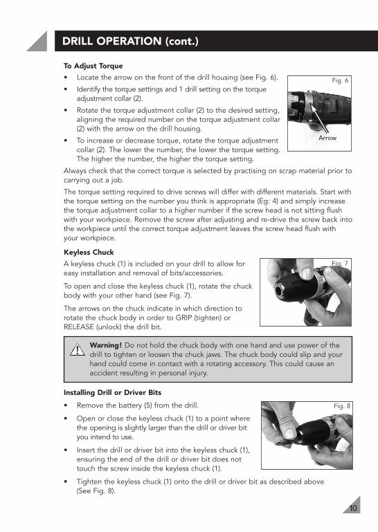
To Adjust Torque
• Locate the arrow on the front of the drill housing (see Fig. 6).
• Identify the torque settings and 1 drill setting on the torqueadjustment collar (2).
• Rotate the torque adjustment collar (2) to the desired setting,aligning the required number on the torque adjustment collar(2) with the arrow on the drill housing.
• To increase or decrease torque, rotate the torque adjustmentcollar (2). The lower the number, the lower the torque setting.The higher the number, the higher the torque setting.
Always check that the correct torque is selected by practising on scrap material prior tocarrying out a job.
The torque setting required to drive screws will differ with different materials. Start withthe torque setting on the number you think is appropriate (Eg: 4) and simply increasethe torque adjustment collar to a higher number if the screw head is not sitting flushwith your workpiece. Remove the screw after adjusting and re-drive the screw back intothe workpiece until the correct torque adjustment leaves the screw head flush with your workpiece.
Keyless Chuck
A keyless chuck (1) is included on your drill to allow foreasy installation and removal of bits/accessories.
To open and close the keyless chuck (1), rotate the chuckbody with your other hand (see Fig. 7).
The arrows on the chuck indicate in which direction torotate the chuck body in order to GRIP (tighten) orRELEASE (unlock) the drill bit.
Warning! Do not hold the chuck body with one hand and use power of thedrill to tighten or loosen the chuck jaws. The chuck body could slip and yourhand could come in contact with a rotating accessory. This could cause anaccident resulting in personal injury.
Installing Drill or Driver Bits
• Remove the battery (5) from the drill.
• Open or close the keyless chuck (1) to a point wherethe opening is slightly larger than the drill or driver bityou intend to use.
• Insert the drill or driver bit into the keyless chuck (1),ensuring the end of the drill or driver bit does nottouch the screw inside the keyless chuck (1).
• Tighten the keyless chuck (1) onto the drill or driver bit as described above(See Fig. 8).
DRILL OPERATION (cont.)
10
Fig. 6
Arrow
Fig. 7
Fig. 8
DRILL OPERATION (cont.)
11
Removing Drill/Driver Bits
• Remove the battery (5) from the drill.
• Loosen the keyless chuck (1) as described previously.
• Remove the drill or driver bit from the keyless chuck (1).
Note: Do not handle drill bits without gloves as drill bits and other accessories aresharp or can be hot after use, this can cause personal injury.
General Hints for Drilling in all Materials
• Always use sharp drill bits.
• Mark the place where you would like the hole to be drilled.
• Commence with a slow speed to start the hole (see section "Speed Control"for directions on how to do this).
• Reduce your pressure on the drill when the drill bit is about to break throughthe material.
Metal Drilling
• Support thin material with a piece of scrap wood.
• Use a centre punch to mark the position of the hole.
• If drilling a large hole, use a small size drill bit first to establish a pilot hole thenuse the required large size drill bit.
• Use only HSS (high speed steel) drill bits or those recommended for metal use.
• When drilling into iron or steel, use a cooling lubricant such as thin oil. Withaluminium, use turpentine or paraffin. With brass, copper and cast iron, use nolubricant but withdraw the drill regularly to assist cooling.
Wood Drilling
• Mark the place where you want to drill with a punch or a nail.
• To avoid splintering on breakthrough, either clamp a piece of scrap wood tothe back of your workpiece or continue the hole from the back of the woodwhen the drill bit first breaks through.
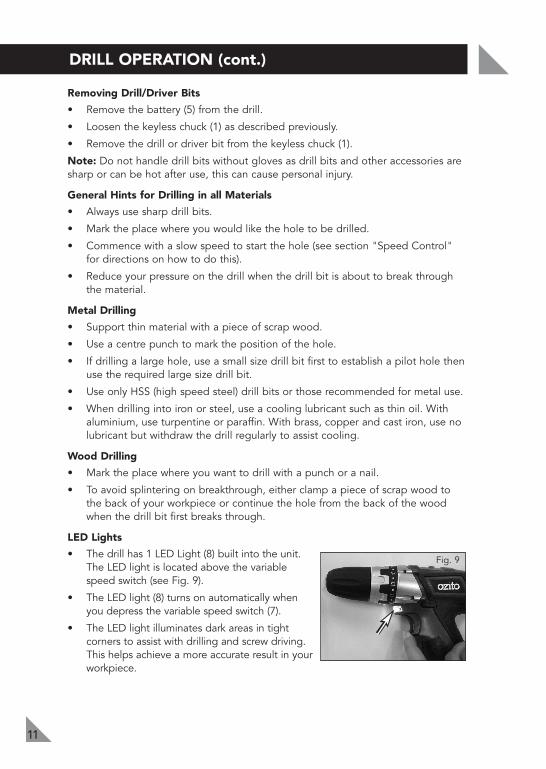
LED Lights
• The drill has 1 LED Light (8) built into the unit.The LED light is located above the variablespeed switch (see Fig. 9).
• The LED light (8) turns on automatically whenyou depress the variable speed switch (7).
• The LED light illuminates dark areas in tightcorners to assist with drilling and screw driving.This helps achieve a more accurate result in yourworkpiece.
Fig. 9

12
SPARE PARTS
MAINTENANCE
Limited spare parts are available subject to availability. Please contact your localBunnings Special Orders Desk to order the required spare parts.
Most common spare parts listed below
Spare Part Part No.
12V Battery Pack SPLIR012-06
Charging Adaptor SPLIR012-15
Charging Stand SPLIR012-16
• When not in use, the drill should be stored in a dry, frost free location, out ofreach of children.
• Keep ventilation slots of the drill clean at all times and prevent any foreign matterfrom entering.
• If the housing of the drill requires cleaning, do not use solvents but a moist softcloth only.
• Blow out the ventilation slots with compressed air periodically .
Note: Ozito Industries will not be responsible for any damage or injuries caused byrepair of the drill by an unauthorised person or by mishandling of the drill.
DESCRIPTION OF SYMBOLS
13
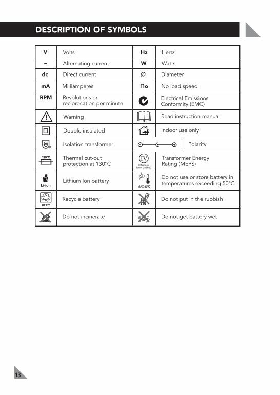
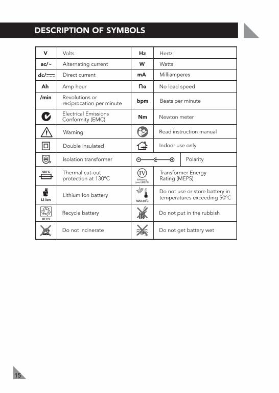
Warning Read instruction manual
V Volts Hz Hertz
~ Alternating current W Watts
dc Direct current ø Diameter
mA Milliamperes no No load speed
Recycle battery Do not put in the rubbish
Isolation transformer Polarity
Do not incinerate Do not get battery wet
Thermal cut-outprotection at 130ºC
Transformer EnergyRating (MEPS)
Double insulated
RPM Revolutions or reciprocation per minute
Indoor use only
Lithium Ion batteryDo not use or store battery in temperatures exceeding 50ºC
Electrical Emissions Conformity (EMC)

1 x 12V Cordless Lithium Ion Drill 1 x Charging cradle 1 x Battery1 x Extension adaptor
1 x Soft bag 1 x AC Charging adaptor 1 x Instruction manual
AUSTRALIA (Head Office)
1 - 23 Letcon Drive, Bangholme, Victoria, Australia 3175Telephone: 1800 069 486Facsimile: +61 3 9238 5588Website: www.ozito.com.auEmail: [email protected]
CONTENTS
Power tools that are no longer usable should not bedisposed of with household waste but in an environmentallyfriendly way. Please recycle where facilities exist. Check withyour local council authority for recycling advice.
Recycling packaging reduces the need for landfill and rawmaterials. Reuse of recycled material decreases pollution in theenvironment. Please recycle packaging where facilities exist.Check with your local council authority for recycling advice.
OZITO INDUSTRIES PTY LTD
14
CARING FOR THE ENVIRONMENT
3 YEAR REPLACEMENT WARRANTY
Your product is guaranteed for a period of 36 months from the original date of purchase and is intended for DIY (Do It Yourself) use only. If a product is defective it will be replaced in accordance with the terms of this warranty. Warranty excludes consumable parts, for example: included accessories. Lithium Ion batteries are covered by a 12 month warranty.
WARNING
The following actions will result in the warranty being void.
Professional, Industrial or high frequency use.If the tool has been operated on a supply voltage other than that specifi ed on the tool.If the tool shows signs of damage or defects caused by or resulting from abuse, accidents or alterations.Failure to perform maintenance as set out within the instruction manual.If the tool is disassembled or tampered with in any way.
OZITOAustralia/New Zealand (Head Offi ce)1-23 Letcon Drive, Bangholme, Victoria, Australia 3175
•••
••
OW7
WARRANTYYOUR WARRANTY FORM SHOULD BE RETAINED BY YOU AT ALL TIMES. IN ORDER
TO MAKE A CLAIM UNDER THIS WARRANTY YOU MUST RETURN THE PRODUCT TO YOUR NEAREST BUNNINGS WAREHOUSE WITH YOUR BUNNINGS REGISTER RECEIPT.
PRIOR TO RETURNING YOUR PRODUCT FOR WARRANTY PLEASE TELEPHONE OUR CUSTOMER SERVICE HELPLINE:
TO ENSURE A SPEEDY RESPONSE PLEASE HAVE THE MODEL NUMBER AND DATE OF PURCHASE AVAILABLE. A CUSTOMER SERVICE REPRESENTATIVE WILL TAKE YOUR CALL AND ANSWER ANY QUESTIONS YOU MAY HAVE RELATING TO THE WARRANTY POLICY
OR PROCEDURE.
The benefi ts provided under this warranty are in addition to other rights and remedies which are available to you at law.Our goods come with guarantees that cannot be excluded at law. You are entitled to a replacement or refund for a major failure and for compensation for any other reasonably foreseeable loss or damage. You are also entitled to have the goods repaired or replaced if the goods fail to be of acceptable quality and the failure does not amount to a major failure. Generally you will be responsible for all costs associated with a claim under this warranty, however, where you have suffered any additional direct loss as a result of a defective product you may be able to claim such expenses by contacting our customer service helpline above.
`Australia 1800 069 486New Zealand 0508 069 486

Cordless Impact Driver12V Li-Ion
Instruction Manual3 Year Replacement Warranty
LID-012WARNING! Read all safety warnings and all instructions. Failure to follow
the warnings and instructions may result in electric shock, fire and /or serious injury.Save all warnings and instructions for future reference.
To view the full range visit: www.ozito.com.au0912
!

Battery power: 12V Charge time: 3 – 5 hoursNo load speed: 0-2000 /minImpact speed: 0 - 3000bpmTorque: 80NmDrive: 6.35mm (1/4”) hex shankBatteries: 2 x 1.3Ah Lithium IonWeight (tool only): 1.05kg
3
97
2
8
SPECIFICATIONS – MODEL NO. LID-012
1
KNOW YOUR PRODUCT
1. Quick release chuck2. Forward/reverse lever3. Battery release button4. Battery (12V Lithium Ion)5. Variable speed switch
6. LED light7. Charging adaptor8. Charging jack9. Charging cradle
5
6
4
1
2
TABLE OF CONTENTS
SPECIFICATIONS ………………………………………..
INTRODUCTION…………………………………………
ELECTRICAL SAFETY…………….………………………
GENERAL POWER TOOL SAFETY WARNINGS………
BATTERY AND CHARGER SAFETY WARNINGS………
ADDITIONAL SAFETY RULES FOR IMPACT DRIVERS….
LITHIUM ION BATTERY AND CHARGER SAFETY FEATURES…………….…………………………
CHARGING YOUR LITHIUM ION BATTERY..…………
INSTALLING OR REMOVING THE BATTERY...………
OPERATION………………………………………………
MAINTENANCE…………….……………………………
SPARE PARTS …………….……………………………...
DESCRIPTION OF SYMBOLS ………………………….
PACK CONTENTS ………………………………………
WARRANTY………………………………………………
Page 1
Page 3
Page 3
Page 4
Page 6
Page 7
Page 8
Page 9
Page 10
Page 11
Page 14
Page 14
Page 15
Page 16
Page 17
INTRODUCTION
3
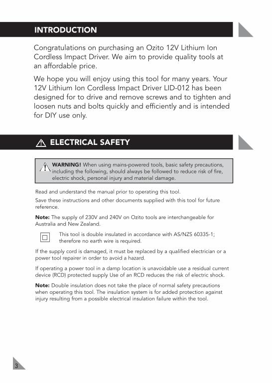
Congratulations on purchasing an Ozito 12V Lithium IonCordless Impact Driver. We aim to provide quality tools atan affordable price.
We hope you will enjoy using this tool for many years. Your12V Lithium Ion Cordless Impact Driver LID-012 has beendesigned for to drive and remove screws and to tighten andloosen nuts and bolts quickly and efficiently and is intendedfor DIY use only.
ELECTRICAL SAFETY
!WARNING! When using mains-powered tools, basic safety precautions,including the following, should always be followed to reduce risk of fire,electric shock, personal injury and material damage.
Read and understand the manual prior to operating this tool.
Save these instructions and other documents supplied with this tool for futurereference.
Note: The supply of 230V and 240V on Ozito tools are interchangeable forAustralia and New Zealand.
This tool is double insulated in accordance with AS/NZS 60335-1; therefore no earth wire is required.
If the supply cord is damaged, it must be replaced by a qualified electrician or apower tool repairer in order to avoid a hazard.
If operating a power tool in a damp location is unavoidable use a residual currentdevice (RCD) protected supply Use of an RCD reduces the risk of electric shock.
Note: Double insulation does not take the place of normal safety precautionswhen operating this tool. The insulation system is for added protection againstinjury resulting from a possible electrical insulation failure within the tool.
!
4
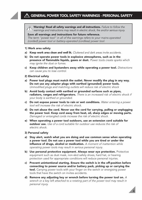
Warning! Read all safety warnings and all instructions. Failure to follow thewarnings and instructions may result in electric shock, fire and/or serious injury.
Save all warnings and instructions for future reference.The term "power tool" in all of the warnings refers to your mains-operated(corded) power tool or battery-operated (cordless) power tool.
1) Work area safety
a) Keep work area clean and well lit. Cluttered and dark areas invite accidents. b) Do not operate power tools in explosive atmospheres, such as in the
presence of flammable liquids, gases or dust. Power tools create sparks whichmay ignite the dust or fumes.
c) Keep children and bystanders away while operating a power tool. Distractionscan cause you to lose control.
2) Electrical safety
a) Power tool plugs must match the outlet. Never modify the plug in any way.Do not use any adapter plugs with earthed (grounded) power tools.Unmodified plugs and matching outlets will reduce risk of electric shock
b) Avoid body contact with earthed or grounded surfaces such as pipes,radiators, ranges and refrigerators. There is an increased risk of electric shock ifyour body is earthed or grounded.
c) Do not expose power tools to rain or wet conditions. Water entering a powertool will increase the risk of electric shock.
d) Do not abuse the cord. Never use the cord for carrying, pulling or unpluggingthe power tool. Keep cord away from heat, oil, sharp edges or moving parts.Damaged or entangled cords increase the risk of electric shock.
e) When operating a power tool outdoors, use an extension cord suitable foroutdoor use. Use of a cord suitable for outdoor use reduces the risk of electric shock.
3) Personal safety
a) Stay alert, watch what you are doing and use common sense when operatinga power tool. Do not use a power tool while you are tired or under theinfluence of drugs, alcohol or medication. A moment of inattention whileoperating power tools may result in serious personal injury.
b) Use personal protective equipment. Always wear eye protection. Protectiveequipment such as dust mask, non-skid safety shoes, hard hat, or hearingprotection used for appropriate conditions will reduce personal injuries.
c) Prevent unintentional starting. Ensure the switch is in the off-position beforeconnecting to power source and/or battery pack, picking up or carrying thetool. Carrying power tools with your finger on the switch or energising powertools that have the switch on invites accidents.
d) Remove any adjusting key or wrench before turning the power tool on. Awrench or a key left attached to a rotating part of the power tool may result inpersonal injury.
!
GENERAL POWER TOOL SAFETY WARNINGS - PERSONAL SAFETY!
5
GENERAL POWER TOOL SAFETY WARNINGS - PERSONAL SAFETY!
e) Do not overreach. Keep proper footing and balance at all times. Thisenables better control of the power tool in unexpected situations.
f) Dress properly. Do not wear loose clothing or jewellery. Keep your hair,clothing and gloves away from moving parts. Loose clothes, jewellery orlong hair can be caught in moving parts.
g) If devices are provided for the connection of dust extraction andcollection facilities, ensure these are connected and properly used. Use ofthese devices can reduce dust-related hazards.
4) Power tool use and care
a) Do not force the power tool. Use the correct power tool for your application.The correct power tool will do the job better and safer at the rate for which it was designed.
b) Do not use the power tool if the switch does not turn it on and off. Anypower tool that cannot be controlled with the switch is dangerous and must be repaired.
c) Disconnect the plug from the power source and/or the battery pack fromthe power tool before making any adjustments, changing accessories, orstoring power tools. Such preventive safety measures reduce the risk ofstarting the power tool accidentally.
d) Store idle power tools out of the reach of children and do not allowpersons unfamiliar with the power tool or these instructions to operatethe power tool. Power tools are dangerous in the hands of untrained users.
e) Maintain power tools. Check for misalignment or binding of moving parts,breakage of parts and any other condition that may affect the powertools operation. If damaged, have the power tool repaired before use.Many accidents are caused by poorly maintained power tools.
f) Keep cutting tools sharp and clean. Properly maintained cutting tools withsharp cutting edges are less likely to bind and are easier to control.
g) Use the power tool, accessories and tool bits etc. in accordance withthese instructions and in the manner intended for the particular type ofpower tool, taking into account the working conditions and the work tobe performed. Use of the power tool for operations different from thoseintended could result in a hazardous situation.
5) Service
a) Have your power tool serviced by a qualified repair person using onlyidentical replacement parts. This will ensure that the safety of the power toolis maintained.
b) If the supply cord is damaged, it must be replaced by the manufacturer, itsservice agent or similarly qualified persons in order to avoid a hazard.
6
BATTERY & CHARGER SAFETY WARNINGS!
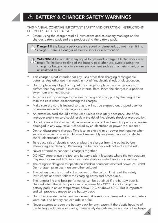
THIS MANUAL CONTAINS IMPORTANT SAFETY AND OPERATING INSTRUCTIONSFOR YOUR BATTERY CHARGER.
• Before using the charger read all instructions and cautionary markings on thecharger, battery pack and the product using the battery pack.
Danger! If the battery pack case is cracked or damaged, do not insert it intocharger. There is a danger of electric shock or electrocution.
WARNING! Do not allow any liquid to get inside charger. Electric shock mayresult. To facilitate cooling of the battery pack after use, avoid placing thecharger or battery pack in a warm environment such as in a metal shed, or anuninsulated trailer.
• This charger is not intended for any uses other than charging rechargeablebatteries. Any other use may result in risk of fire, electric shock or electrocution.
• Do not place any object on top of the charger or place the charger on a softsurface that may result in excessive internal heat. Place the charger in a positionaway from any heat source.
• To reduce risk of damage to the electric plug and cord, pull by the plug ratherthan the cord when disconnecting the charger.
• Make sure the cord is located so that it will not be stepped on, tripped over, orotherwise subjected to damage or stress.
• An extension cord should not be used unless absolutely necessary. Use of animproper extension cord could result in the risk of fire, electric shock or electrocution.
• Do not operate the charger if it has received a sharp blow, been dropped or otherwisedamaged in any way. Have it checked by an electrician or power tool repairer.
• Do not disassemble charger. Take it to an electrician or power tool repairer whenservice or repair is required. Incorrect reassembly may result in a risk of electricshock, electrocution or fire.
• To reduce risk of electric shock, unplug the charger from the outlet beforeattempting any cleaning. Removing the battery pack will not reduce this risk.
• Never attempt to connect 2 chargers together.
• DO NOT store or use the tool and battery pack in locations where the temperaturemay reach or exceed 40ºC (such as inside sheds or metal buildings in summer).
• The charger is designed to operate on standard household electrical power (240 volts).Do not attempt to use it on any other voltage!
• The battery pack is not fully charged out of the carton. First read the safetyinstructions and then follow the charging notes and procedures.
• The longest life and best performance can be obtained if the battery pack ischarged when the air temperature is between 18 - 24ºC. Do not charge thebattery pack in an air temperature below 10ºC or above 40ºC. This is importantand will prevent damage to the battery pack.
• Do not incinerate the battery pack even if it is seriously damaged or is completelyworn out. The battery can explode in a fire.
• Never attempt to open the battery pack for any reason. If the plastic housing ofthe battery pack breaks or cracks, immediately discontinue use and do not recharge.
!
!
7
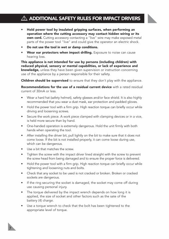
• Hold power tool by insulated gripping surfaces, when performing anoperation where the cutting accessory may contact hidden wiring or itsown cord. Cutting accessory contacting a "live" wire may make exposed metalparts of the power tool "live" and could give the operator an electric shock.
• Do not use the tool in wet or damp conditions.
• Wear ear protectors when impact drilling. Exposure to noise can cause hearing loss.
This appliance is not intended for use by persons (including children) withreduced physical, sensory or mental capabilities, or lack of experience andknowledge, unless they have been given supervision or instruction concerninguse of the appliance by a person responsible for their safety.
Children should be supervised to ensure that they don't play with the appliance.
Recommendations for the use of a residual current device with a rated residualcurrent of 30mA or less.
• Wear a hard hat (safety helmet), safety glasses and/or face shield. It is also highlyrecommended that you wear a dust mask, ear protection and padded gloves.
• Hold the power tool with a firm grip. High reaction torque can briefly occur whiledriving and loosening screws.
• Secure the work piece. A work piece clamped with clamping devices or in a vice,is held more secure than by hand.
• One-handed operation is extremely dangerous. Hold the unit firmly with bothhands when operating the tool.
• After installing the driver bit, pull lightly on the bit to make sure that it does notcome loose. If the bit is not installed properly, it can come loose during use,which can be dangerous.
• Use a bit that matches the screw.
• Tighten the screw with the impact driver lined straight with the screw to preventthe screw head from being damaged and to ensure the proper force is delivered.
• Hold the power tool with a firm grip. High reaction torque can briefly occur whiletightening and loosening nuts and bolts.
• Check that any socket to be used is not cracked or broken. Broken or crackedsockets are dangerous.
• If the ring securing the socket is damaged, the socket may come off duringuse causing personal injury.
• The torque delivered by the impact wrench depends on how long it isapplied, the size of socket and other factors such as the sate of the battery (4) charge.
• Use a torque wrench to check that the bolt has been tightened to theappropriate level of torque.
ADDITIONAL SAFETY RULES FOR IMPACT DRIVERS!
8
LITHIUM ION BATTERY AND CHARGER SAFETY FEATURES
ADDITIONAL SAFETY RULES FOR IMPACT DRIVERS (cont.)!
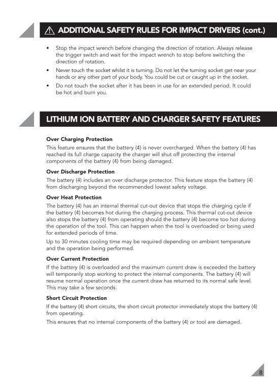
• Stop the impact wrench before changing the direction of rotation. Always releasethe trigger switch and wait for the impact wrench to stop before switching thedirection of rotation.
• Never touch the socket whilst it is turning. Do not let the turning socket get near yourhands or any other part of your body. You could be cut or caught up in the socket.
• Do not touch the socket after it has been in use for an extended period. It couldbe hot and burn you.
Over Charging Protection
This feature ensures that the battery (4) is never overcharged. When the battery (4) hasreached its full charge capacity the charger will shut off protecting the internalcomponents of the battery (4) from being damaged.
Over Discharge Protection
The battery (4) includes an over discharge protector. This feature stops the battery (4)from discharging beyond the recommended lowest safety voltage.
Over Heat Protection
The battery (4) has an internal thermal cut-out device that stops the charging cycle ifthe battery (4) becomes hot during the charging process. This thermal cut-out devicealso stops the battery (4) from operating should the battery (4) become too hot duringthe operation of the tool. This can happen when the tool is overloaded or being usedfor extended periods of time.
Up to 30 minutes cooling time may be required depending on ambient temperatureand the operation being performed.
Over Current Protection
If the battery (4) is overloaded and the maximum current draw is exceeded the batterywill temporarily stop working to protect the internal components. The battery (4) willresume normal operation once the current draw has returned to its normal safe level.This may take a few seconds.
Short Circuit Protection
If the battery (4) short circuits, the short circuit protector immediately stops the battery (4)from operating.
This ensures that no internal components of the battery (4) or tool are damaged.

9
The drill has been shipped in a low charge condition, andrequires charging prior to use.• Insert the charging jack (8) into the charging cradle (9) (see
Fig. 1). Plug the charging adaptor (7) into a mains poweroutlet. Ensure that the charging cradle (9) is on a flat surface.
• Insert the battery (4) into the charging cradle (9). The recessof the battery terminals will have a firm connection. Uponproper contact the red and green LED light will illuminate onthe charging cradle (9) to indicate the battery is charging.
• The battery (4) will take 3 – 5 hours to charge. Chargingstarts automatically. Remove the battery (4) from the charger after 5 hours.
Note: If LED light on the charging cradle (9) fails to illuminate.• Check the charging adaptor (7) is securely plugged into the wall outlet and is
switched on.• Check the battery (4) is firmly seated onto the charging cradle (9).• Check the charging jack (8) is securely connected into the socket of the
charging cradle (9).
Initial Charge• When the unit is on charge, both the red and green LED light will illuminate. • When the battery is fully charged, only the green LED light will be illuminated.
The red LED will go out, indicating the battery is no longer being charged. • Charge your battery for 3 – 5 hours then use it until it runs down and only
slowly operates.• The battery will not reach its full capacity until it has been recharged 4 to 5 times.
Important Charging Notes• The charging adaptor (7) and battery (4) may become warm to touch while
charging. This is a normal condition, and does not indicate a problem.• Use the charger at normal room temperature whenever possible. To prevent
overheating, do not cover the charger and do not charge the battery (4) indirect sunlight or near heat sources.
• If the battery (4) does not charge properly:-1. Check current at mains power outlet by plugging in a lamp or other appliance.2. If charging problems persist, have the complete drill checked by an
electrician or a power tool repairer.
Note: If battery (4) is flat and only the green LED light is illuminated, refer toThermal voltage protection note below cooling maybe required.
Thermal voltage protection indicationIn the event that the thermal or voltage protection circuit has been activated thebattery will cease to operate. This can happen when the tool has been used forextended periods or worked hard with large drill bits or accessories.If you place the battery on the charger the LED lights will give you the appearance thatthe battery is fully charged. Leave the battery on the charger to charge for 3-5 hours. The battery may take the full 5 hours to charge as the battery may need to cooldown or the protection circuit to be reset. This will then allow the charger to begincharging the battery and resume normal operation.
CHARGING YOUR LITHIUM ION BATTERY
Fig. 1
INSTALLING OR REMOVING THE BATTERY
10
!
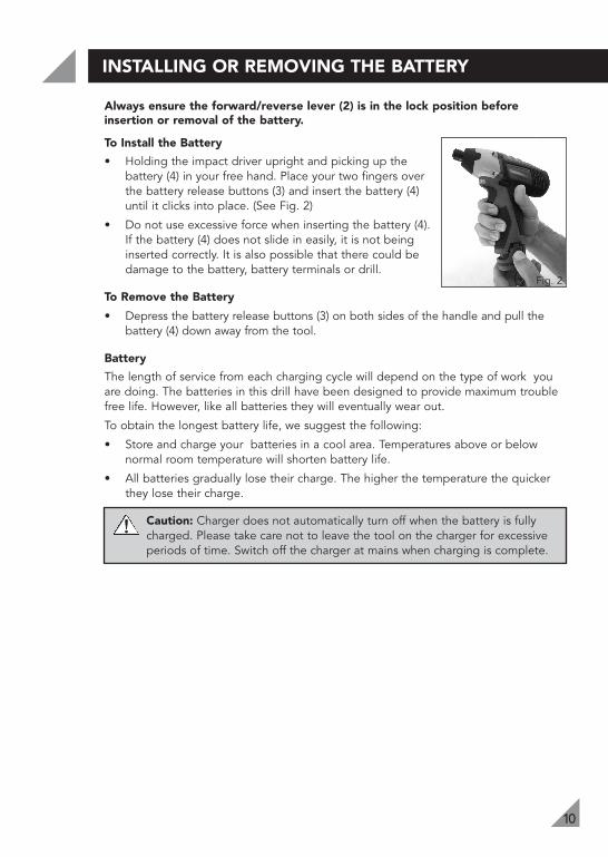
Always ensure the forward/reverse lever (2) is in the lock position beforeinsertion or removal of the battery.
To Install the Battery
• Holding the impact driver upright and picking up thebattery (4) in your free hand. Place your two fingers overthe battery release buttons (3) and insert the battery (4)until it clicks into place. (See Fig. 2)
• Do not use excessive force when inserting the battery (4).If the battery (4) does not slide in easily, it is not beinginserted correctly. It is also possible that there could bedamage to the battery, battery terminals or drill.
To Remove the Battery
• Depress the battery release buttons (3) on both sides of the handle and pull thebattery (4) down away from the tool.
Battery
The length of service from each charging cycle will depend on the type of work youare doing. The batteries in this drill have been designed to provide maximum troublefree life. However, like all batteries they will eventually wear out.
To obtain the longest battery life, we suggest the following:
• Store and charge your batteries in a cool area. Temperatures above or belownormal room temperature will shorten battery life.
• All batteries gradually lose their charge. The higher the temperature the quickerthey lose their charge.
Caution: Charger does not automatically turn off when the battery is fullycharged. Please take care not to leave the tool on the charger for excessiveperiods of time. Switch off the charger at mains when charging is complete.
Fig. 2
OPERATION
11
Insertion and removal of driver bits and sockets
WARNING! Always ensure the forward/reverse lever (2) is in the lockposition and remove the battery (4) from the tool before inserting orremoving a bit or socket or when making any adjustments to your tool.
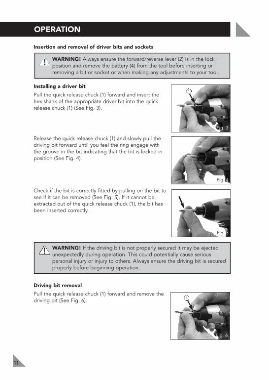
Installing a driver bit
Pull the quick release chuck (1) forward and insert thehex shank of the appropriate driver bit into the quickrelease chuck (1) (See Fig. 3).
Release the quick release chuck (1) and slowly pull thedriving bit forward until you feel the ring engage withthe groove in the bit indicating that the bit is locked inposition (See Fig. 4).
Check if the bit is correctly fitted by pulling on the bit tosee if it can be removed (See Fig. 5). If it cannot beextracted out of the quick release chuck (1), the bit hasbeen inserted correctly.
WARNING! If the driving bit is not properly secured it may be ejectedunexpectedly during operation. This could potentially cause seriouspersonal injury or injury to others. Always ensure the driving bit is securedproperly before beginning operation.
Driving bit removal
Pull the quick release chuck (1) forward and remove thedriving bit (See Fig. 6).
Fig. 3
!
Fig. 6
Fig. 4
Fig. 5
!
1
1
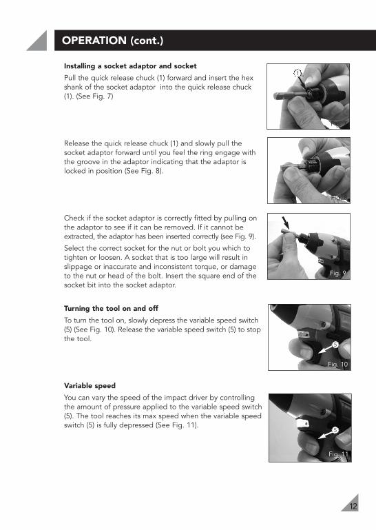
Installing a socket adaptor and socket
Pull the quick release chuck (1) forward and insert the hexshank of the socket adaptor into the quick release chuck(1). (See Fig. 7)
Release the quick release chuck (1) and slowly pull thesocket adaptor forward until you feel the ring engage withthe groove in the adaptor indicating that the adaptor islocked in position (See Fig. 8).
Check if the socket adaptor is correctly fitted by pulling onthe adaptor to see if it can be removed. If it cannot beextracted, the adaptor has been inserted correctly (see Fig. 9).
Select the correct socket for the nut or bolt you which totighten or loosen. A socket that is too large will result inslippage or inaccurate and inconsistent torque, or damageto the nut or head of the bolt. Insert the square end of thesocket bit into the socket adaptor.
Turning the tool on and off
To turn the tool on, slowly depress the variable speed switch(5) (See Fig. 10). Release the variable speed switch (5) to stopthe tool.
Variable speed
You can vary the speed of the impact driver by controllingthe amount of pressure applied to the variable speed switch(5). The tool reaches its max speed when the variable speedswitch (5) is fully depressed (See Fig. 11).
12
OPERATION (cont.)
Fig. 7
Fig. 8
Fig. 9
Fig. 10
Fig. 11
1
5
5
13
OPERATION (cont.)
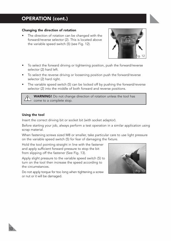
Changing the direction of rotation
• The direction of rotation can be changed with theforward/reverse selector (2). This is located abovethe variable speed switch (5) (see Fig. 12).
• To select the forward driving or tightening position, push the forward/reverseselector (2) hard left.
• To select the reverse driving or loosening position push the forward/reverseselector (2) hard right.
• The variable speed switch (5) can be locked off by pushing the forward/reverseselector (2) into the middle of both forward and reverse positions.
WARNING! Do not change direction of rotation unless the tool has come to a complete stop.
Using the tool
Insert the correct driving bit or socket bit (with socket adaptor).
Before starting your job, always perform a test operation in a similar application usingscrap material.
When fastening screws sized M8 or smaller, take particular care to use light pressureon the variable speed switch (5) for fear of damaging the fixture.
Hold the tool pointing straight in line with the fastenerand apply sufficient forward pressure to stop the bitfrom slipping off the fastener (See Fig. 13).
Apply slight pressure to the variable speed switch (5) toturn on the tool then increase the speed according tothe circumstances.
Do not apply torque for too long when tightening a screwor nut or it will be damaged.
Fig. 13
Fig. 12
!

14
MAINTENANCE
!
SPARE PARTS
Limited spare parts are available subject to availability. Please contact your localBunnings Special Orders Desk to order the required spare parts.
Most common spare parts listed below
Spare Part Part No.
Battery (12V Lithium Ion) SPLIR012-06
Charging Adaptor SPLIR012-15
Charging Stand SPLIR012-16
• When not in use, the tool should be stored in a dry, frost free location, out ofreach of children.
• Keep ventilation slots of the tool clean at all times and prevent any foreign matterfrom entering.
• After each use, blow air through the tool housing to ensure it is free from all dustparticles which may build up. Build up of dust particles may cause the tool tooverheat and fail.
• If the enclosure of the tool requires cleaning do not use solvents but a moist softcloth only. Never let any liquid get inside the tool; never immerse any part of thetool into a liquid.
Note: Ozito Industries will not be responsible for any damage or injuries caused byrepair of the tool by an unauthorised person or by mishandling of the tool.
WARNING! DISCONNECT THE CHARGER FROM THE MAINS POWEROUTLET BEFORE CLEANING.
15
DESCRIPTION OF SYMBOLS
Warning Read instruction manual
V Volts Hz Hertz
ac/~ Alternating current W Watts
Direct current
no No load speed
Recycle battery Do not put in the rubbish
Isolation transformer Polarity
Do not incinerate Do not get battery wet
Thermal cut-outprotection at 130ºC
Transformer EnergyRating (MEPS)
Double insulated
/min Revolutions or reciprocation per minute
Ah Amp hour
Nm Newton meter
Indoor use only
Lithium Ion batteryDo not use or store battery in temperatures exceeding 50ºC
Electrical Emissions Conformity (EMC)
bpm Beats per minute
mA Milliamperes dc/

CARING FOR THE ENVIRONMENT
16
PACK CONTENTS
OZITO INDUSTRIES PTY LTD
1 x 12V Cordless Impact Driver2 x Batteries (12V Lithium-ion)4 x Sockets2 x CRV bits
1 x Charger1 x Socket holder1 x Charger base 1 x Instruction manual
AUSTRALIA (Head Office)
1 - 23 Letcon Drive, Bangholme, Victoria, Australia 3175Telephone: 1800 069 486Facsimile: +61 3 9238 5588Website: www.ozito.com.auEmail: [email protected]
Power tools that are no longer usable should not bedisposed of with household waste but in an environmentallyfriendly way. Please recycle where facilities exist. Check withyour local council authority for recycling advice.
Recycling packaging reduces the need for landfill and rawmaterials. Reuse of recycled material decreases pollution in theenvironment. Please recycle packaging where facilities exist.Check with your local council authority for recycling advice.
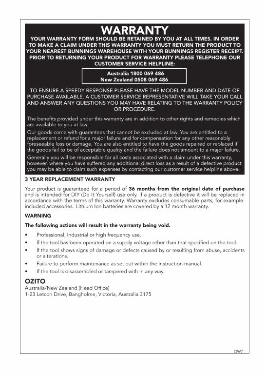
3 YEAR REPLACEMENT WARRANTY
Your product is guaranteed for a period of 36 months from the original date of purchase and is intended for DIY (Do It Yourself) use only. If a product is defective it will be replaced in accordance with the terms of this warranty. Warranty excludes consumable parts, for example: included accessories. Lithium Ion batteries are covered by a 12 month warranty.
WARNING
The following actions will result in the warranty being void.
Professional, Industrial or high frequency use.If the tool has been operated on a supply voltage other than that specifi ed on the tool.If the tool shows signs of damage or defects caused by or resulting from abuse, accidents or alterations.Failure to perform maintenance as set out within the instruction manual.If the tool is disassembled or tampered with in any way.
OZITOAustralia/New Zealand (Head Offi ce)1-23 Letcon Drive, Bangholme, Victoria, Australia 3175
•••
••
OW7
WARRANTYYOUR WARRANTY FORM SHOULD BE RETAINED BY YOU AT ALL TIMES. IN ORDER
TO MAKE A CLAIM UNDER THIS WARRANTY YOU MUST RETURN THE PRODUCT TO YOUR NEAREST BUNNINGS WAREHOUSE WITH YOUR BUNNINGS REGISTER RECEIPT.
PRIOR TO RETURNING YOUR PRODUCT FOR WARRANTY PLEASE TELEPHONE OUR CUSTOMER SERVICE HELPLINE:
TO ENSURE A SPEEDY RESPONSE PLEASE HAVE THE MODEL NUMBER AND DATE OF PURCHASE AVAILABLE. A CUSTOMER SERVICE REPRESENTATIVE WILL TAKE YOUR CALL AND ANSWER ANY QUESTIONS YOU MAY HAVE RELATING TO THE WARRANTY POLICY
OR PROCEDURE.
The benefi ts provided under this warranty are in addition to other rights and remedies which are available to you at law.Our goods come with guarantees that cannot be excluded at law. You are entitled to a replacement or refund for a major failure and for compensation for any other reasonably foreseeable loss or damage. You are also entitled to have the goods repaired or replaced if the goods fail to be of acceptable quality and the failure does not amount to a major failure. Generally you will be responsible for all costs associated with a claim under this warranty, however, where you have suffered any additional direct loss as a result of a defective product you may be able to claim such expenses by contacting our customer service helpline above.
`Australia 1800 069 486New Zealand 0508 069 486

Multi Function Tool 12V Li-Ion Instruction Manual3 Year Replacement Warranty
MFT-012WARNING: Read all safety warnings and all instructions. Failure to follow the
warnings and instructions may result in electric shock, fire and/or serious injury.Save all warnings and instructions for future reference.
To view the full range visit: www.ozito.com.au0912
!
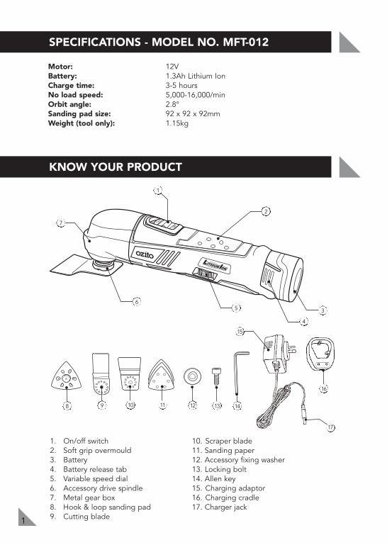
Motor: 12VBattery: 1.3Ah Lithium IonCharge time: 3-5 hoursNo load speed: 5,000-16,000/minOrbit angle: 2.8°Sanding pad size: 92 x 92 x 92mmWeight (tool only): 1.15kg
SPECIFICATIONS - MODEL NO. MFT-012
1
1. On/off switch 2. Soft grip overmould 3. Battery4. Battery release tab 5. Variable speed dial6. Accessory drive spindle 7. Metal gear box8. Hook & loop sanding pad9. Cutting blade
10. Scraper blade 11. Sanding paper12. Accessory fixing washer13. Locking bolt 14. Allen key15. Charging adaptor 16. Charging cradle 17. Charger jack
1
2
7
3
8
16
14
56
4
9 10 11 12 13
KNOW YOUR PRODUCT
17
15
2
TABLE OF CONTENTS
SPECIFICATIONS…………………………………………..
KNOW YOUR PRODUCT………………………………….
INTRODUCTION…………………………………………..
ELECRICAL SAFETY……………………………………….
GENERAL POWER TOOL SAFETY WARNINGS…………
MULTI FUNCTION TOOL SAFETY WARNINGS………
LITHIUM ION BATTERY AND CHARGER SAFETY FEATURES……….………………………………
CHARGING THE LITHIUM ION BATTERY……………….
INSTALLING OR REMOVING THE BATTERY……………
ASSEMBLY………………………………..…………………
OPERATION………………………………………………..
MAINTENANCE……………………………………………
SPARE PARTS………………………………………………
DESCRIPTION OF SYMBOLS…………………………….
CONTENTS…………………………………………………
WARRANTY…………………………………………………
Page 1
Page 1
Page 3
Page 3
Page 4
Page 6
Page 7
Page 8
Page 9
Page 10
Page 11
Page 14
Page 15
Page 16
Page 17
Page 18
!
!
INTRODUCTION
3
Congratulations on purchasing an Ozito Lithium Ion MultiFunction Tool. We aim to provide quality tools at anaffordable price.We hope you will enjoy using this tool for many years. YourLithium Ion Multi Function Tool MFT-012 has been designedfor sanding, chiselling, cutting and many additionalapplications and is intended for DIY use only.
THIS MANUAL CONTAINS IMPORTANT SAFETY AND OPERATINGINSTRUCTIONS FOR YOUR BATTERY CHARGER.
• Before using the charger, read all instructions and cautionary markings oncharger, battery pack and product using the battery pack.
WARNING! If the battery pack case is cracked or damaged, do notinsert into charger. There is a danger of electric shock or electrocution.
WARNING! Don’t allow any liquid to get inside charger. Electric shockmay result. To facilitate cooling of the battery pack after use, avoidplacing the charger or battery pack in a warm environment such as in ametal shed, or an uninsulated trailer.
• This charger is not intended for any uses other than charging rechargeablebatteries. Any other use may result in risk of fire, electric shock or electrocution.
• Do not place any object on top of the charger or place the charger on a softsurface that may result in excessive internal heat. Place the charger in aposition away from any heat source.
• To reduce risk of damage to the electric plug and cord, pull by the plug ratherthan the cord when disconnecting the charger.
• Make sure cord is located so that it will not be stepped on, tripped over, orotherwise subjected to damage or stress.
• An extension cord should not be used unless absolutely necessary. Use of animproper extension cord could result in the risk of fire, electric shock orelectrocution.
• Do not operate charger if it has received a sharp blow, been dropped orotherwise damaged in any way. Have it checked by an electrician or power tool repairer.
• Do not disassemble charger. Take it to an electrician or power tool repairerwhen service or repair is required. Incorrect reassembling may result in a risk ofelectric shock, electrocution or fire.
• To reduce risk of electric shock, unplug charger from the outlet beforeattempting any cleaning. Removing the battery pack will not reduce this risk.
ELECTRICAL SAFETY!
!
4
GENERAL POWER TOOL SAFETY WARNINGS
• Never attempt to connect 2 chargers together.
• DO NOT store or use the tool and battery pack in locations where the temperaturemay reach or exceed 40ºC (such as outside sheds or metal buildings in summer).
• The charger is designed to operate on standard household electrical power (240 volts).Do not attempt to use it on any other voltage!
The battery pack is not fully charged out of the carton. First read the safety instructionsand then follow the charging notes and procedures.
• The longest life and best performance can be obtained if the battery pack ischarged when the air temperature is between 18 - 24ºC. Do not charge the batterypack in an air temperature below 10ºC or above 40ºC. This is important and willprevent damage to the battery pack.
• Do not incinerate the battery pack even if it is seriously damaged or is completelyworn out. The battery can explode in a fire.
• Never attempt to open the battery pack for any reason. If the plastic housing of thebattery pack breaks or cracks, immediately discontinue use and do not recharge.
WARNING! Read all safety warnings and all instructions. Failure to follow the warnings and instructions may result in electric shock, fire and/orserious injury.
Save all warnings and instructions for future reference.The term “power tool" in all of the warnings refers to your mains-operated(corded) power tool or battery-operated (cordless) power tool.
1) Work area safety
a) Keep work area clean and well lit. Cluttered or dark areas invite accidents.b) Do not operate power tools in explosive atmospheres, such as in the
presence of flammable liquids, gases or dust. Power tools create sparks whichmay ignite the dust or fumes.
c) Keep children and bystanders away while operating a power tool. Distractionscan cause you to lose control.
2) Electrical safety
a) Power tool plugs must match the outlet. Never modify the plug in any way.Do not use any adapter plugs with earthed (grounded) power tools. Unmodified plugs and matching outlets will reduce risk of electric shock.
b) Avoid body contact with earthed or grounded surfaces, such as pipes, radiators, ranges and refrigerators. There is an increased risk of electric shock if your body is earthed or grounded.
c) Do not expose power tools to rain or wet conditions. Water entering a powertool will increase the risk of electric shock.
d) Do not abuse the cord. Never use the cord for carrying, pulling or unpluggingthe power tool. Keep cord away from heat, oil, sharp edges or moving parts.Damaged or entangled cords increase the risk of electric shock.
!
ELECTRICAL SAFETY (cont.)!
5
e) When operating a power tool outdoors, use an extension cord suitable foroutdoor use. Use of a cord suitable for outdoor use reduces the risk of electricshock.
f) If operating a power tool in a damp location is unavoidable, use a residualcurrent device (RCD) protected supply. Use of an RCD reduces the risk of electric shock.
3) Personal safety
a) Stay alert, watch what you are doing and use common sense whenoperating a power tool. Do not use a power tool while you are tired orunder the influence of drugs, alcohol or medication. A moment ofinattention while operating power tools may result in serious personal injury.
b) Use personal protective equipment. Always wear eye protection. Protectiveequipment such as dust mask, non-skid safety shoes, hard hat, or hearingprotection used for appropriate conditions will reduce personal injuries.
c) Prevent unintentional starting. Ensure the switch is in the off-positionbefore connecting to power source and/or battery pack, picking up orcarrying the tool. Carrying power tools with your finger on the switch orenergising power tools that have the switch on invites accidents.
d) Remove any adjusting key or wrench before turning the power tool on. Awrench or a key left attached to a rotating part of the power tool may result inpersonal injury.
e) Do not overreach. Keep proper footing and balance at all times. Thisenables better control of the power tool in unexpected situations.
f) Dress properly. Do not wear loose clothing or jewellery. Keep your hair, clothing and gloves away from moving parts. Loose clothes, jewellery orlong hair can be caught in moving parts.
g) If devices are provided for the connection of dust extraction and collectionfacilities, ensure these are connected and properly used. Use of dustcollection can reduce dust-related hazards.
4) Power tool use and carea) Do not force the power tool. Use the correct power tool for your
application. The correct power tool will do the job better and safer at the ratefor which it was designed.
b) Do not use the power tool if the switch does not turn it on and off. Any powertool that cannot be controlled with the switch is dangerous and must be repaired.
c) Disconnect the plug from the power source and/or the battery pack fromthe power tool before making any adjustments, changing accessories, or storing power tools. Such preventive safety measures reduce the risk ofstarting the power tool accidentally.
d) Store idle power tools out of the reach of children and do not allowpersons unfamiliar with the power tool or these instructions to operatethe power tool. Power tools are dangerous in the hands of untrained users.
e) Maintain power tools. Check for misalignment or binding of moving parts,breakage of parts and any other condition that may affect the powertool’s operation. If damaged, have the power tool repaired before use.Many accidents are caused by poorly maintained power tools.
f) Keep cutting tools sharp and clean. Properly maintained cutting tools withsharp cutting edges are less likely to bind and are easier to control.
GENERAL POWER TOOL SAFETY WARNINGS!
MULTI FUNCTION TOOL SAFETY WARNINGS
6
g) Use the power tool, accessories and tool bits etc. in accordance with theseinstructions, taking into account the working conditions and the work to beperformed. Use of the power tool for operations different from those intendedcould result in a hazardous situation.
5) Battery tool use and carea) Recharge only with the charger specified by the manufacturer. A charger that
is suitable for one type of battery pack may create a risk of fire when used withanother battery pack.
b) Use power tools only with specifically designated battery packs. Use of anyother battery packs may create a risk of injury and fire.
c) When battery pack is not in use, keep it away from other metal objects, likepaper clips, coins, keys, nails, screws or other small metal objects, that canmake a connection from one terminal to another. Shorting the battery terminalstogether may cause burns or a fire.
d) Under abusive conditions, liquid may be ejected from the battery; avoidcontact. If contact accidentally occurs, flush with water. If liquid contacts eyes,additionally seek medical help. Liquid ejected from the battery may causeirritation or burns.
6) Servicea) Have your power tool serviced by a qualified repair person using only
identical replacement parts. This will ensure that the safety of the power tool ismaintained.
b) If the supply cord is damaged, it must be replaced by the manufacturer, itsservice agent or similarly qualified persons in order to avoid a hazard.
This appliance is not intended for use by persons (including children) withreduced physical, sensory or mental capabilities, or lack of experience andknowledge, unless they have been given supervision or instruction concerning use ofthe appliance by a person responsible for their safety.
Recommendations for the use of a residual current device with a rated residualcurrent of 30mA or less.
!
GENERAL POWER TOOL SAFETY WARNINGS!
7
LITHIUM BATTERY AND CHARGER SAFETY FEATURES
Over Charging Protection
This feature ensures that the battery is never overcharged. When the battery hasreached it’s full charge capacity the charger will shut off protecting the internalcomponents of the battery from being damaged.
Over Discharge Protection
An internal component of the battery pack is an over discharge protector. Thisfeature will stop the battery from discharging beyond the recommended lowestsafety voltage.
Over Heat Protection
The battery has an internal Thermister cut off sensor which will cease the chargingcycle if the battery becomes hot during the charging process. This Thermistersensor will also stop the battery from operating should the battery become too hotduring the operation of the tool. This can happen when the tool is overloaded orbeing used for extended periods of time .
Up to 30min in cooling time may be required depending on ambient temperatureand operation being performed.
Over Current Protection
Should the battery be overloaded and the maximum current draw be exceededthe battery will temporarily stop working to protect the internal components. Thebattery will resume to normal operation once the excessive current draw hasreturned to normal safe level. This may take a few seconds.
Short Circuit Protection
If the battery pack was to short circuit the short circuit protector would immediatelystop the battery pack from operating.
This will ensure that no further internal components of the battery or the tools aredamaged.

8
CHARGING THE LITHIUM ION BATTERY
The multi function tool has been shipped in a low charge condition, and requirescharging prior to use.
Initial Charging
1. Ensure that the charging cradle (16) is on a flat surface. Insertthe charging jack (17) into the charging cradle (16).
2. Plug the charging adaptor (15) into a power outlet.3. Insert the battery (3) into the charging cradle (16) (Fig. 1). The
recess of the battery terminals will have a firm connection.Upon proper contact the red and green light will illuminate onthe charging cradle (16).
4. To obtain optimum battery performance and life, charge thebatteries for 5-7 hours and use the tool until it runs down. Repeat this charge anddischarge process approximately 4-5 times.
Note: If the light on the charging cradle (16) fails to come on:• Check the charging adaptor (15) is securely plugged into the wall outlet and is
switched on.• Check the charging jack (17) is securely connected to the charging cradle (16) socket.• Check the battery (3) is firmly seated onto the charging cradle (16).
Normal Charging
• When the unit is on charge the red and green light will be on display. • Charging starts automatically. The battery (2) will take 3-5 hours to charge. • When the battery (2) is fully charged, the red light will go out, and only the green
light will be on display.• Remove the battery (2) from the charger after 5 hours.
Important Charging Notes
• The charger adaptor (15) and battery (3) may become warm to touch whilecharging. This is normal, and does not indicate a problem.
• Use the charger at normal room temperature whenever possible. To preventoverheating, do not cover the charger and do not charge the battery (3) in directsunlight or near heat sources.
NOTE: If battery is flat and displays green charged LED, refer to thermal voltageprotection note below cooling maybe required.
Thermal voltage protection indication
In the event that the thermal or voltage protection circuit has been activated thebattery will cease to operate. This can happen when the tool has been used forextended periods or worked hard with large drill bits or accessories.If you place the battery on the charger the LED lights will give you the appearance that thebattery is fully charged. Leave the battery on the charger to charge for 3-5 hours. The battery may take the full 5 hours to charge as the battery may need to cool downor the protection circuit to be reset. This will then allow the charger to begin chargingthe battery and resume normal operation.
Fig. 1
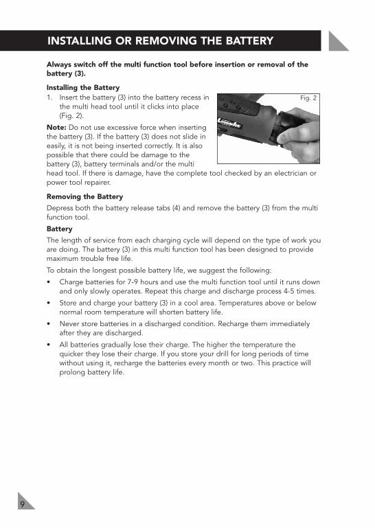
Always switch off the multi function tool before insertion or removal of thebattery (3).
Installing the Battery1. Insert the battery (3) into the battery recess in
the multi head tool until it clicks into place(Fig. 2).
Note: Do not use excessive force when insertingthe battery (3). If the battery (3) does not slide ineasily, it is not being inserted correctly. It is alsopossible that there could be damage to thebattery (3), battery terminals and/or the multihead tool. If there is damage, have the complete tool checked by an electrician orpower tool repairer.
Removing the Battery
Depress both the battery release tabs (4) and remove the battery (3) from the multifunction tool.
Battery
The length of service from each charging cycle will depend on the type of work youare doing. The battery (3) in this multi function tool has been designed to providemaximum trouble free life.
To obtain the longest possible battery life, we suggest the following:
• Charge batteries for 7-9 hours and use the multi function tool until it runs downand only slowly operates. Repeat this charge and discharge process 4-5 times.
• Store and charge your battery (3) in a cool area. Temperatures above or belownormal room temperature will shorten battery life.
• Never store batteries in a discharged condition. Recharge them immediatelyafter they are discharged.
• All batteries gradually lose their charge. The higher the temperature thequicker they lose their charge. If you store your drill for long periods of timewithout using it, recharge the batteries every month or two. This practice willprolong battery life.
INSTALLING OR REMOVING THE BATTERY
9
Fig. 2
10
ASSEMBLY
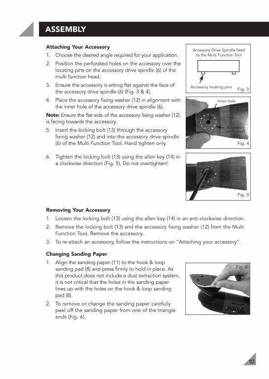
Attaching Your Accessory
1. Choose the desired angle required for your application.
2. Position the perforated holes on the accessory over thelocating pins on the accessory drive spindle (6) of themulti function head.
3. Ensure the accessory is sitting flat against the face ofthe accessory drive spindle (6) (Fig. 3 & 4).
4. Place the accessory fixing washer (12) in alignment withthe inner hole of the accessory drive spindle (6).
Note: Ensure the flat side of the accessory fixing washer (12)is facing towards the accessory.
5. Insert the locking bolt (13) through the accessoryfixing washer (12) and into the accessory drive spindle(6) of the Multi Function Tool. Hand tighten only.
6. Tighten the locking bolt (13) using the allen key (14) ina clockwise direction (Fig. 5). Do not overtighten!
Removing Your Accessory
1. Loosen the locking bolt (13) using the allen key (14) in an anti-clockwise direction.
2. Remove the locking bolt (13) and the accessory fixing washer (12) from the MultiFunction Tool. Remove the accessory.
3. To re-attach an accessory, follow the instructions on “Attaching your accessory”.
Changing Sanding Paper
1. Align the sanding paper (11) to the hook & loopsanding pad (8) and press firmly to hold in place. Asthis product does not include a dust extraction system,it is not critical that the holes in the sanding paperlines up with the holes on the hook & loop sandingpad (8).
2. To remove or change the sanding paper carefullypeel off the sanding paper from one of the triangleends (Fig. 6).
Fig. 3
Accessory Drive Spindle fixedto the Multi Function Tool
Accessory locating pins
Fig. 6
Fig. 5
Fig. 4
Accessoryperforated
holes
Inner hole
OPERATION
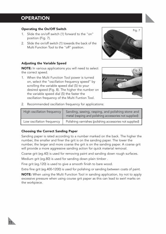
Operating the On/Off Switch
1. Slide the on/off switch (1) forward to the "on"position (Fig. 7).
2. Slide the on/off switch (1) towards the back of theMulti Function Tool to the "off" position.
Adjusting the Variable Speed
NOTE: In various applications you will need to selectthe correct speed.
1. When the Multi Function Tool power is turnedon, select the “oscillation frequency speed” byscrolling the variable speed dial (5) to yourdesired speed (Fig. 8). The higher the number onthe variable speed dial (5) the faster theoscillation frequency of the Multi Funtion Tool.
2. Recommended oscillation frequency for applications:
High oscillation frequency Sanding, sawing, rasping, and polishing stone and metal (rasping and polishing accessories not supplied)
Low oscillation frequency Polishing varnishes (polishing accessories not supplied)
Choosing the Correct Sanding Paper
Sanding paper is rated according to a number marked on the back. The higher thenumber, the smaller and finer the grit is on the sanding paper. The lower thenumber, the larger and more coarse the grit is on the sanding paper. A coarse gritwill provide a more aggressive sanding action for quick material removal.
Coarse grit (eg.40) is used for removing paint and sanding down rough surfaces.
Medium grit (eg.80) is used for sanding down plain timber .
Fine grit (eg.120) is used to give a smooth finish to bare wood.
Extra fine grit (eg.400-1200) is used for polishing or sanding between coats of paint.
NOTE: When using the Multi Function Tool in sanding application, try not to applyexcessive pressure when using course grit paper as this can lead to swirl marks onthe workpiece.
11
Fig. 7
Fig. 8
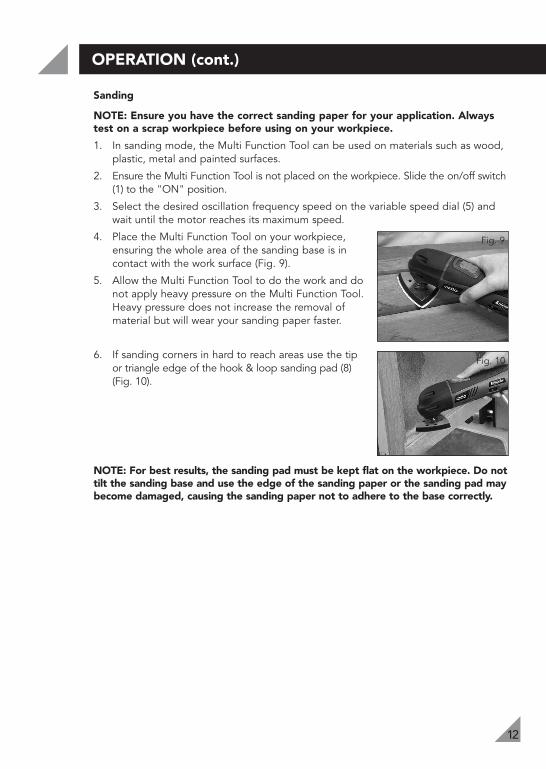
12
OPERATION (cont.)
Sanding
NOTE: Ensure you have the correct sanding paper for your application. Alwaystest on a scrap workpiece before using on your workpiece.
1. In sanding mode, the Multi Function Tool can be used on materials such as wood,plastic, metal and painted surfaces.
2. Ensure the Multi Function Tool is not placed on the workpiece. Slide the on/off switch(1) to the "ON" position.
3. Select the desired oscillation frequency speed on the variable speed dial (5) andwait until the motor reaches its maximum speed.
4. Place the Multi Function Tool on your workpiece,ensuring the whole area of the sanding base is incontact with the work surface (Fig. 9).
5. Allow the Multi Function Tool to do the work and donot apply heavy pressure on the Multi Function Tool.Heavy pressure does not increase the removal ofmaterial but will wear your sanding paper faster.
6. If sanding corners in hard to reach areas use the tipor triangle edge of the hook & loop sanding pad (8)(Fig. 10).
NOTE: For best results, the sanding pad must be kept flat on the workpiece. Do nottilt the sanding base and use the edge of the sanding paper or the sanding pad maybecome damaged, causing the sanding paper not to adhere to the base correctly.
Fig. 9
Fig. 10
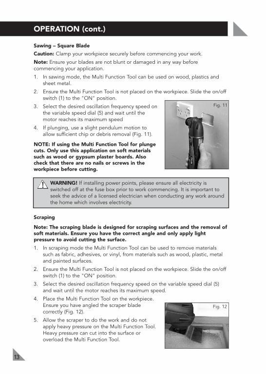
!
13
OPERATION (cont.)
Sawing – Square Blade
Caution: Clamp your workpiece securely before commencing your work.
Note: Ensure your blades are not blunt or damaged in any way beforecommencing your application.
1. In sawing mode, the Multi Function Tool can be used on wood, plastics andsheet metal.
2. Ensure the Multi Function Tool is not placed on the workpiece. Slide the on/offswitch (1) to the "ON" position.
3. Select the desired oscillation frequency speed onthe variable speed dial (5) and wait until themotor reaches its maximum speed
4. If plunging, use a slight pendulum motion toallow sufficient chip or debris removal (Fig. 11).
NOTE: If using the Multi Function Tool for plungecuts. Only use this application on soft materialssuch as wood or gypsum plaster boards. Alsocheck that there are no nails or screws in theworkpiece before cutting.
WARNING! If installing power points, please ensure all electricity isswitched off at the fuse box prior to work commencing. It is important toseek the advice of a licensed electrician when conducting any work aroundthe home which involves electricity.
Scraping
Note: The scraping blade is designed for scraping surfaces and the removal ofsoft materials. Ensure you have the correct angle and only apply lightpressure to avoid cutting the surface.
1. In scraping mode the Multi Function Tool can be used to remove materialssuch as fabric, adhesives, or vinyl, from materials such as wood, plastic, metaland painted surfaces.
2. Ensure the Multi Function Tool is not placed on the workpiece. Slide the on/offswitch (1) to the "ON" position.
3. Select the desired oscillation frequency speed on the variable speed dial (5)and wait until the motor reaches its maximum speed.
4. Place the Multi Function Tool on the workpiece.Ensure you have angled the scraper bladecorrectly (Fig. 12).
5. Allow the scraper to do the work and do notapply heavy pressure on the Multi Function Tool.Heavy pressure can cut into the surface oroverload the Multi Function Tool.
Fig. 11
Fig. 12

MAINTENANCE
14
• When not in use, the Multi Function Tool should be stored in a dry, frost freelocation. Keep out of reach of children.
• Keep the ventilation slots of the Multi Function Tool clean at all times. If possible,prevent foreign matter from entering the vents.
• After each use, blow air through the Multi Function Tool housing to ensure it isfree from all dust particles which may build up. Build up of dust particles maycause the Multi Function Tool to overheat and fail.
• If the enclosure of the Multi Function Tool requires cleaning do not use solventsbut a moist soft cloth only. Never let any liquid get inside the Multi Function Tool.Never immerse any part of the Multi Function Tool into a liquid.
Note: Ozito Industries will not be responsible for any damage or injuries caused bythe repair of the tool by an unauthorised person or by mishandling of the tool.

SPARE PARTS
15
Limited spare parts are available subject to availability. Please contact your localBunnings Special Orders Desk to order the required spare parts.
Most common spare parts listed below
Spare Part Part No.
Inner Flange SPDMP012-18
Locking Screw & Washer SPDMP012-21A
12V Battery Pack SPLIR012-06
Charging Adaptor SPLIR012-15
Charging Stand SPLIR012-16
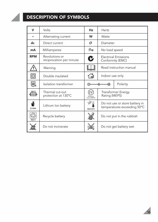
DESCRIPTION OF SYMBOLS
16
Warning Read instruction manual
V Volts Hz Hertz
~ Alternating current W Watts
dc Direct current ø Diameter
mA Milliamperes no No load speed
Recycle battery Do not put in the rubbish
Isolation transformer Polarity
Do not incinerate Do not get battery wet
Thermal cut-outprotection at 130ºC
Transformer EnergyRating (MEPS)
Double insulated
RPM Revolutions or reciprocation per minute
Indoor use only
Lithium Ion batteryDo not use or store battery in temperatures exceeding 50ºC
Electrical Emissions Conformity (EMC)

CARING FOR THE ENVIRONMENT
17
OZITO INDUSTRIES PTY LTD
AUSTRALIA (Head Office)1-23 Letcon Drive, Bangholme Victoria, Australia, 3175 Telephone: 1800 069 486Facsimile: +61 3 9238 5588Website: www.ozito.com.auEmail: [email protected]
1 x 12V Cordless Multi Faction Tool1 x 12V Li-Ion battery pack1 x Hook & Loop sanding pad1 x Cutting blade
1 x Scraper blade3 x Sanding papers1 x Allen key1 x instruction manual
Power tools that are no longer usable should not bedisposed of with household waste but in an environmentallyfriendly way. Please recycle where facilities exist. Check withyour local council authority for recycling advice.
Recycling packaging reduces the need for landfill and rawmaterials. Reuse of recycled material decreases pollution in theenvironment. Please recycle packaging where facilities exist.Check with your local council authority for recycling advice.
CONTENTS

3 YEAR REPLACEMENT WARRANTY
Your product is guaranteed for a period of 36 months from the original date of purchase and is intended for DIY (Do It Yourself) use only. If a product is defective it will be replaced in accordance with the terms of this warranty. Warranty excludes consumable parts, for example: hook & loop sanding pad, cutting blade, scraper blade, sanding papers, allen key.Lithium Ion batteries are covered by a 12 month warranty.
WARNING
The following actions will result in the warranty being void.
Professional, Industrial or high frequency use.If the tool has been operated on a supply voltage other than that specifi ed on the tool.If the tool shows signs of damage or defects caused by or resulting from abuse, accidents or alterations.Failure to perform maintenance as set out within the instruction manual.If the tool is disassembled or tampered with in any way.
OZITOAustralia/New Zealand (Head Offi ce)1-23 Letcon Drive, Bangholme, Victoria, Australia 3175
•••
••
OW7
WARRANTYYOUR WARRANTY FORM SHOULD BE RETAINED BY YOU AT ALL TIMES. IN ORDER
TO MAKE A CLAIM UNDER THIS WARRANTY YOU MUST RETURN THE PRODUCT TO YOUR NEAREST BUNNINGS WAREHOUSE WITH YOUR BUNNINGS REGISTER RECEIPT.
PRIOR TO RETURNING YOUR PRODUCT FOR WARRANTY PLEASE TELEPHONE OUR CUSTOMER SERVICE HELPLINE:
TO ENSURE A SPEEDY RESPONSE PLEASE HAVE THE MODEL NUMBER AND DATE OF PURCHASE AVAILABLE. A CUSTOMER SERVICE REPRESENTATIVE WILL TAKE YOUR CALL AND ANSWER ANY QUESTIONS YOU MAY HAVE RELATING TO THE WARRANTY POLICY
OR PROCEDURE.
The benefi ts provided under this warranty are in addition to other rights and remedies which are available to you at law.Our goods come with guarantees that cannot be excluded at law. You are entitled to a replacement or refund for a major failure and for compensation for any other reasonably foreseeable loss or damage. You are also entitled to have the goods repaired or replaced if the goods fail to be of acceptable quality and the failure does not amount to a major failure. Generally you will be responsible for all costs associated with a claim under this warranty, however, where you have suffered any additional direct loss as a result of a defective product you may be able to claim such expenses by contacting our customer service helpline above.
`Australia 1800 069 486New Zealand 0508 069 486