Embed Size (px)
Citation preview

11111ASRock 775i65G Motherboard
Eng
lish
Eng
lish
Eng
lish
Eng
lish
Eng
lish
Copyright Notice:Copyright Notice:Copyright Notice:Copyright Notice:Copyright Notice:No part of this installation guide may be reproduced, transcribed, transmitted, or trans-lated in any language, in any form or by any means, except duplication of documen-tation by the purchaser for backup purpose, without written consent of ASRock Inc.Products and corporate names appearing in this guide may or may not be registeredtrademarks or copyrights of their respective companies, and are used only for identifica-tion or explanation and to the owners’ benefit, without intent to infringe.
Disclaimer:Disclaimer:Disclaimer:Disclaimer:Disclaimer:Specifications and information contained in this guide are furnished for informationaluse only and subject to change without notice, and should not be constructed as acommitment by ASRock. ASRock assumes no responsibility for any errors or omissionsthat may appear in this guide.With respect to the contents of this guide, ASRock does not provide warranty of any kind,either expressed or implied, including but not limited to the implied warranties orconditions of merchantability or fitness for a particular purpose. In no event shallASRock, its directors, officers, employees, or agents be liable for any indirect, special,incidental, or consequential damages (including damages for loss of profits, loss ofbusiness, loss of data, interruption of business and the like), even if ASRock has beenadvised of the possibility of such damages arising from any defect or error in the guideor product.
This device complies with Part 15 of the FCC Rules. Operation is subject to thefollowing two conditions:(1) this device may not cause harmful interference, and(2) this device must accept any interference received, including interference that
may cause undesired operation.
Published June 2012Copyright©2012 ASRock INC. All rights reserved.
CALIFORNIA, USA ONLYThe Lithium battery adopted on this motherboard contains Perchlorate, a toxicsubstance controlled in Perchlorate Best Management Practices (BMP) regulationspassed by the California Legislature. When you discard the Lithium battery inCalifornia, USA, please follow the related regulations in advance.“Perchlorate Material-special handling may apply, seewww.dtsc.ca.gov/hazardouswaste/perchlorate”
ASRock Website: http://www.asrock.com

ASRock 775i65G Motherboard22222
Motherboard LMotherboard LMotherboard LMotherboard LMotherboard Layoutayoutayoutayoutayout
Eng
lishEn
glish
Eng
lishEn
glish
Eng
lish
1 ATX 12V Connector (ATX12V2) 15 Clear CMOS Jumper (CLRCMOS0)2 775-Pin CPU Socket 16 USB 2.0 Header (USB67)3 North Bridge Controller 17 Infrared Module Header (IR1)4 CPU Fan Connector (CPU_FAN1) 18 Floppy Connector (FLOPPY1)5 184-pin DDR DIMM Slots (DDR1- 2) 19 Internal Audio Connector: CD1 (Black)6 Secondary IDE Connector (IDE2, Black) 20 Internal Audio Connector: AUX1 (White)7 Primary IDE Connector (IDE1, Blue) 21 Front Panel Audio Header (AUDIO1)8 South Bridge Controller 22 JR1 / JL1 Jumpers9 Secondary Serial ATA Connector (SATA2) 23 PCI Slots (PCI1- 3)10 Primary Serial ATA Connector (SATA1) 24 BIOS FWH Chip11 Chassis Fan Connector (CHA_FAN1) 25 AGP Slot (1.5V_AGP1)12 System Panel Header (PANEL1) 26 Shared USB 2.0 Header (USB4_5)13 Power LED Header (PLED1) 27 ATX Power Connector (ATXPWR1)14 Chassis Speaker Header (SPEAKER1)
DD
R1
(64
/72
bit
,1
84
-pin
mo
du
le)
DD
R2
(64
/72
bit
,1
84
-pin
mo
du
le)
1.5V_AGP1
ATX12V2
SA
TA
2S
AT
A1
AUX1 CD1
USB 2.0T: USB0B: USB1
Top:RJ-45
To
p:
Lin
eIn
Ce
nte
r:L
ine
Ou
t
Bo
ttom
:M
icIn
USB 2.0T: USB4B: USB5
PCI1
4MbBIOS
SuperI/O
USB67
1
IR1
1
PANEL 1
SPEAKER1
1
FLOPPY1
CH
A_
FA
N1CMOS
Battery
Intel865G
ChipsetID
E1
IDE
2
1
AUDIO1
AudioCODEC
CPU_FAN1
AT
XP
WR
1
LANPHY
IntelICH5
20.3cm (8.0 in)
24
.4c
m(9
.6in
)
77
5i6
5G
1
US
B4
_5
1 2 43 5
7
6
8
9
11
10
131415
12
16171819202122
23
27
PCI2
PCI3
CLRCMOS0
1
JR1 JL1
HDLED RESET
PLED PWRBTN
1
USB 2.0T: USB2B: USB3
PS
2M
ou
se
PS
2K
ey
bo
ard
PA
RA
LL
EL
PO
RT
CO
M1
VG
A1
ErP
/Eu
PR
ea
dy
RoHS
FS
B1
06
6F
SB
80
0
PLED1
1
24
26
25

33333ASRock 775i65G Motherboard
Eng
lish
Eng
lish
Eng
lish
Eng
lish
Eng
lish
I/O PI/O PI/O PI/O PI/O Panelanelanelanelanel
1 2
9101112
6
78
4
3
5
1 PS/2 Mouse Port (Green) 7 Shared USB 2.0 Ports (USB45)2 Parallel Port 8 USB 2.0 Ports (USB01)
* 3 RJ-45 Port 9 USB 2.0 Ports (USB23)4 Line In (Light Blue) 10 VGA Port 5 Line Out (Lime) 11 Serial Port: COM16 Microphone (Pink) 12 PS/2 Keyboard Port (Purple)
* There are two LED next to the LAN port. Please refer to the table below for the LAN port LED indications.
LAN Port LED Indications SPEED LED Status Description Yellow 10Mbps connection Green 100Mbps connection
LAN Port
10Mbps 100Mbps

ASRock 775i65G Motherboard44444
1. Introduction1. Introduction1. Introduction1. Introduction1. IntroductionThank you for purchasing ASRock 775i65G motherboard, a reliable motherboardproduced under ASRock’s consistently stringent quality control. It delivers excellentperformance with robust design conforming to ASRock’s commitment to quality andendurance.This Quick Installation Guide contains introduction of the motherboard and step-by-step installation guide. More detailed information of the motherboard can be found inthe user manual presented in the Support CD.
Because the motherboard specifications and the BIOS software mightbe updated, the content of this manual will be subject to change withoutnotice. In case any modifications of this manual occur, the updatedversion will be available on ASRock website without further notice. Youmay find the latest VGA cards and CPU support lists on ASRock websiteas well. ASRock website http://www.asrock.comIf you require technical support related to this motherboard, please visitour website for specific information about the model you are using.www.asrock.com/support/index.asp
1.1 P1.1 P1.1 P1.1 P1.1 Packackackackackage Contentsage Contentsage Contentsage Contentsage ContentsASRock 7775i65G Motherboard
(Micro ATX Form Factor: 9.6-in x 8.0-in, 24.4 cm x 20.3 cm)ASRock 775i65G Quick Installation GuideASRock 775i65G Support CDOne 80-conductor Ultra ATA 66/100 IDE Ribbon CableOne Serial ATA (SATA) Data Cable (Optional)One I/O Panel Shield
Eng
lishEn
glish
Eng
lishEn
glish
Eng
lish
55555ASRock 775i65G Motherboard
Eng
lish
Eng
lish
Eng
lish
Eng
lish
Eng
lish
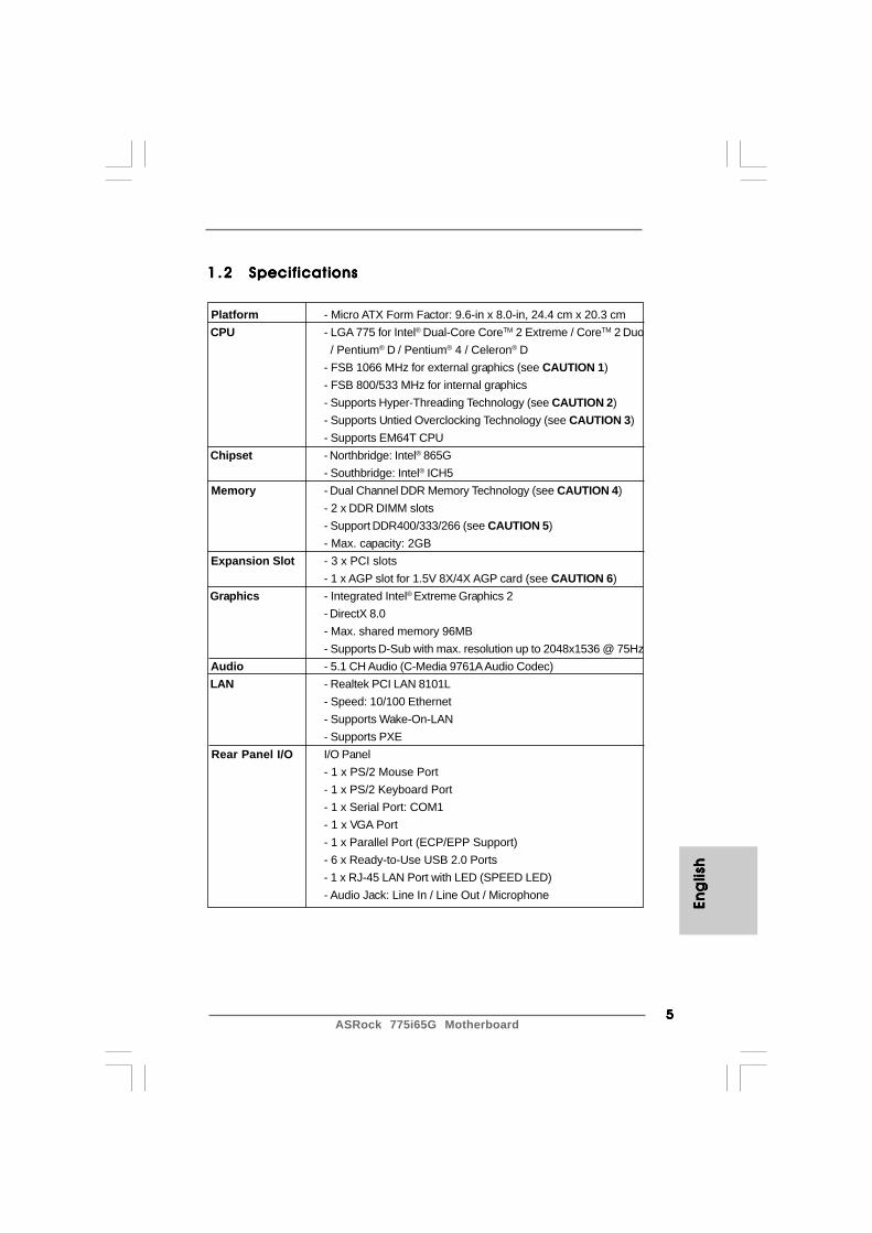
1 .21 .21 .21 .21 .2 SpecificationsSpecificationsSpecificationsSpecificationsSpecifications
Platform - Micro ATX Form Factor: 9.6-in x 8.0-in, 24.4 cm x 20.3 cm CPU - LGA 775 for Intel® Dual-Core CoreTM 2 Extreme / CoreTM 2 Duo
/ Pentium® D / Pentium® 4 / Celeron® D- FSB 1066 MHz for external graphics (see CAUTION 1)- FSB 800/533 MHz for internal graphics- Supports Hyper-Threading Technology (see CAUTION 2)- Supports Untied Overclocking Technology (see CAUTION 3)- Supports EM64T CPU
Chipset - Northbridge: Intel® 865G- Southbridge: Intel® ICH5
Memory - Dual Channel DDR Memory Technology (see CAUTION 4)- 2 x DDR DIMM slots- Support DDR400/333/266 (see CAUTION 5)- Max. capacity: 2GB
Expansion Slot - 3 x PCI slots- 1 x AGP slot for 1.5V 8X/4X AGP card (see CAUTION 6)
Graphics - Integrated Intel® Extreme Graphics 2- DirectX 8.0- Max. shared memory 96MB- Supports D-Sub with max. resolution up to 2048x1536 @ 75Hz
Audio - 5.1 CH Audio (C-Media 9761A Audio Codec) LAN - Realtek PCI LAN 8101L
- Speed: 10/100 Ethernet- Supports Wake-On-LAN- Supports PXE
Rear Panel I/O I/O Panel- 1 x PS/2 Mouse Port- 1 x PS/2 Keyboard Port- 1 x Serial Port: COM1- 1 x VGA Port- 1 x Parallel Port (ECP/EPP Support)- 6 x Ready-to-Use USB 2.0 Ports- 1 x RJ-45 LAN Port with LED (SPEED LED)- Audio Jack: Line In / Line Out / Microphone

ASRock 775i65G Motherboard66666
Eng
lishEn
glish
Eng
lishEn
glish
Eng
lish
Connector - 2 x SATA 1.5Gb/s connectors (No Support for “RAID” and “Hot Plug” functions)- 2 x ATA100 IDE connectors (support 4 x IDE devices)- 1 x Floppy connector- 1 x IR header- 1 x Power LED header- 1 x CPU Fan connector (4-pin)- 1 x Chassis Fan connector (3-pin)- 20 pin ATX power connector- 4 pin 12V power connector- CD in header- AUX in header- Front panel audio connector- 2 x USB 2.0 headers (support 4 USB 2.0 ports; 2 of them are shared with USB45) (see CAUTION 7)
BIOS Feature - 4Mb AMI Legal BIOS- Supports “Plug and Play”- ACPI 1.1 Compliance Wake Up Events- Supports jumperfree- SMBIOS 2.3.1 Support
Support CD - Drivers, Utilities, AntiVirus Software (Trial Version), CyberLink MediaEspresso 6.5 Trial, ASRock MAGIX Multimedia Suite - OEM
Unique Feature - ASRock APP Charger (see CAUTION 8)- Hybrid Booster:
- CPU Frequency Stepless Control (see CAUTION 9)- ASRock U-COP (see CAUTION 10)- Boot Failure Guard (B.F.G.)
Hardware - CPU Temperature Sensing Monitor - Chassis Temperature Sensing
- CPU Fan Tachometer- Chassis Fan Tachometer- CPU Quiet Fan- Voltage Monitoring: +12V, +5V, +3.3V, Vcore
OS - Microsoft® Windows® 98SE/ME/2000/XP compliant Certifications - FCC, CE, WHQL * For detailed product information, please visit our website: http://www.asrock.com

77777ASRock 775i65G Motherboard
Eng
lish
Eng
lish
Eng
lish
Eng
lish
Eng
lish
CAUTION!1. FSB1066-CPU is supported only when you install AGP VGA card into
AGP slot. Besides, if you use a FSB1066-CPU on this motherboard,please adopt a DDR400 CL2.5 memory module.
2. About the setting of “Hyper Threading Technology”, please check page29 of “User Manual” in the support CD.
3. This motherboard supports Untied Overclocking Technology. Please read“Untied Overclocking Technology” on page 19 for details.
4. This motherboard supports Dual Channel Memory Technology. Beforeyou implement Dual Channel Memory Technology, make sure to readthe installation guide of memory modules on page 13 for properinstallation.
5. Please check the table below for the memory support frequency and itscorresponding CPU FSB frequency.
CPU FSB Frequency Memory Support Frequency 800 DDR266, DDR320*, DDR400
533 DDR266, DDR333
* When you use an FSB800-CPU on this motherboard, it will run atDDR320 if you adopt a DDR333 memory module.
6. Do NOT use a 3.3V AGP card on the AGP slot of this motherboard!It may cause permanent damage!
7. Power Management for USB 2.0 works fine under Microsoft® Windows®
XP SP1 or SP2 / 2000 SP4. It may not work properly under Microsoft®
Windows® 98/ ME.8. If you desire a faster, less restricted way of charging your Apple devices,
such as iPhone/iPod/iPad Touch, ASRock has prepared a wonderfulsolution for you - ASRock APP Charger. Simply installing the APP Chargerdriver, it makes your iPhone charged much quickly from your computerand up to 40% faster than before. ASRock APP Charger allows you toquickly charge many Apple devices simultaneously and even supportscontinuous charging when your PC enters into Standby mode (S1),hibernation mode (S4) or power off (S5). With APP Charger driverinstalled, you can easily enjoy the marvelous charging experience thanever.ASRock website: http://www.asrock.com/Feature/AppCharger/index.asp
WARNINGPlease realize that there is a certain risk involved with overclocking, includingadjusting the setting in the BIOS, applying Untied Overclocking Technology, or usingthe third-party overclocking tools. Overclocking may affect your system stability, oreven cause damage to the components and devices of your system. It should bedone at your own risk and expense. We are not responsible for possible damagecaused by overclocking.
ASRock 775i65G Motherboard88888
Eng
lishEn
glish
Eng
lishEn
glish
Eng
lish
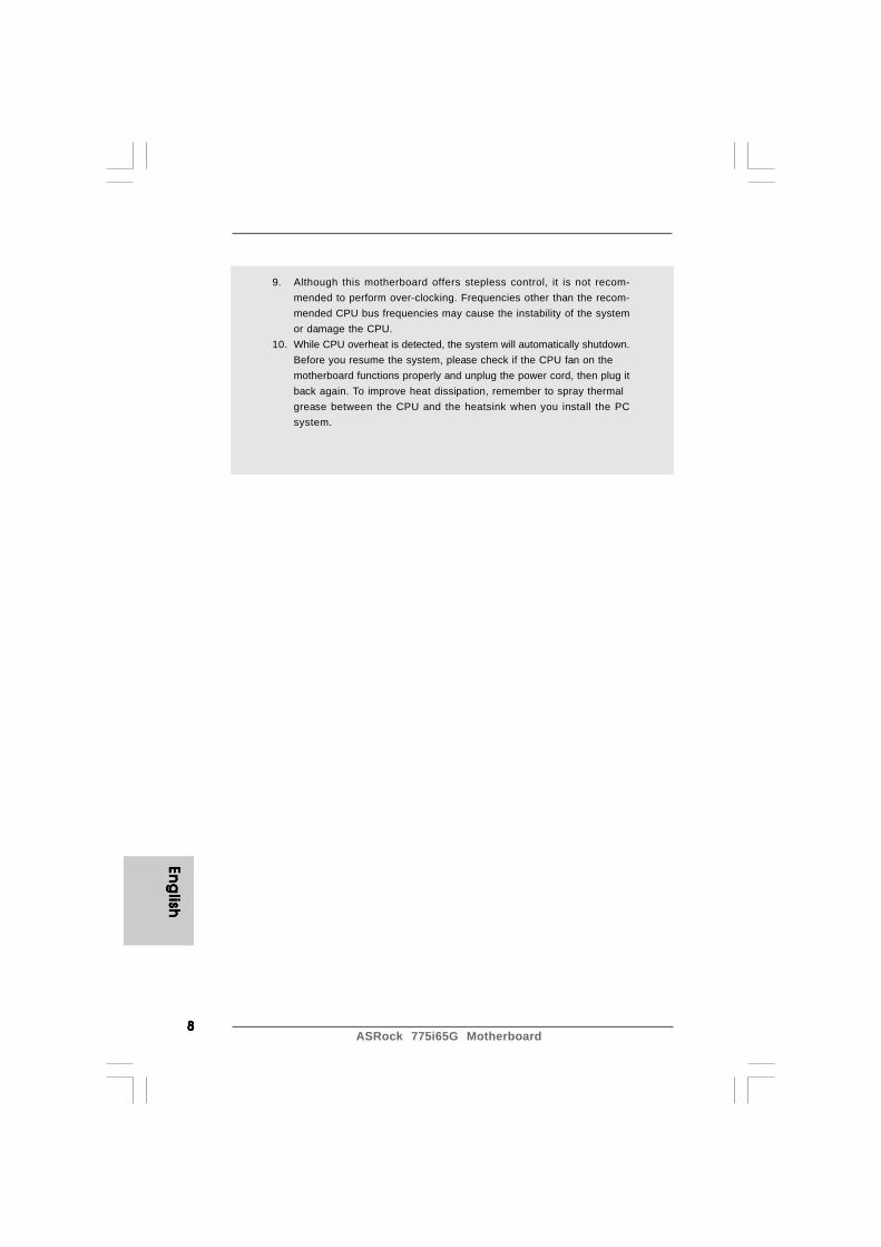
9. Although this motherboard offers stepless control, it is not recom-mended to perform over-clocking. Frequencies other than the recom-mended CPU bus frequencies may cause the instability of the systemor damage the CPU.
10. While CPU overheat is detected, the system will automatically shutdown.Before you resume the system, please check if the CPU fan on themotherboard functions properly and unplug the power cord, then plug itback again. To improve heat dissipation, remember to spray thermalgrease between the CPU and the heatsink when you install the PCsystem.
99999ASRock 775i65G Motherboard
Eng
lish
Eng
lish
Eng
lish
Eng
lish
Eng
lish
2. Installation2. Installation2. Installation2. Installation2. Installation775i65G is a Micro ATX form factor (9.6" x 8.0", 24.4 x 20.3 cm) motherboard. Before youinstall the motherboard, study the configuration of your chassis toensure that the motherboard fits into it.
Make sure to unplug the power cord before installing or removing themotherboard. Failure to do so may cause physical injuries to you anddamages to motherboard components.
2.1 Screw Holes2.1 Screw Holes2.1 Screw Holes2.1 Screw Holes2.1 Screw HolesPlace screws into the holes indicated by circles to secure the motherboard to the chassis.
Do not over-tighten the screws! Doing so may damage the motherboard.
2.2 Pre-installation Precautions2.2 Pre-installation Precautions2.2 Pre-installation Precautions2.2 Pre-installation Precautions2.2 Pre-installation PrecautionsTake note of the following precautions before you install motherboard components orchange any motherboard settings.
1. Unplug the power cord from the wall socket before touching any component.2. To avoid damaging the motherboard components due to static electricity, NEVER
place your motherboard directly on the carpet or the like. Also remember to usea grounded wrist strap or touch a safety grounded object before you handlecomponents.
3. Hold components by the edges and do not touch the ICs.4. Whenever you uninstall any component, place it on a grounded antistatic pad or
in the bag that comes with the component.
Before you install or remove any component, ensure that the power isswitched off or the power cord is detached from the power supply. Failure todo so may cause severe damage to the motherboard, peripherals, and/orcomponents.
ASRock 775i65G Motherboard1 01 01 01 01 0
Eng
lishEn
glish
Eng
lishEn
glish
Eng
lish
Lift Lever Up to 90°
CPU Marked Corner
Socket Marked Corner
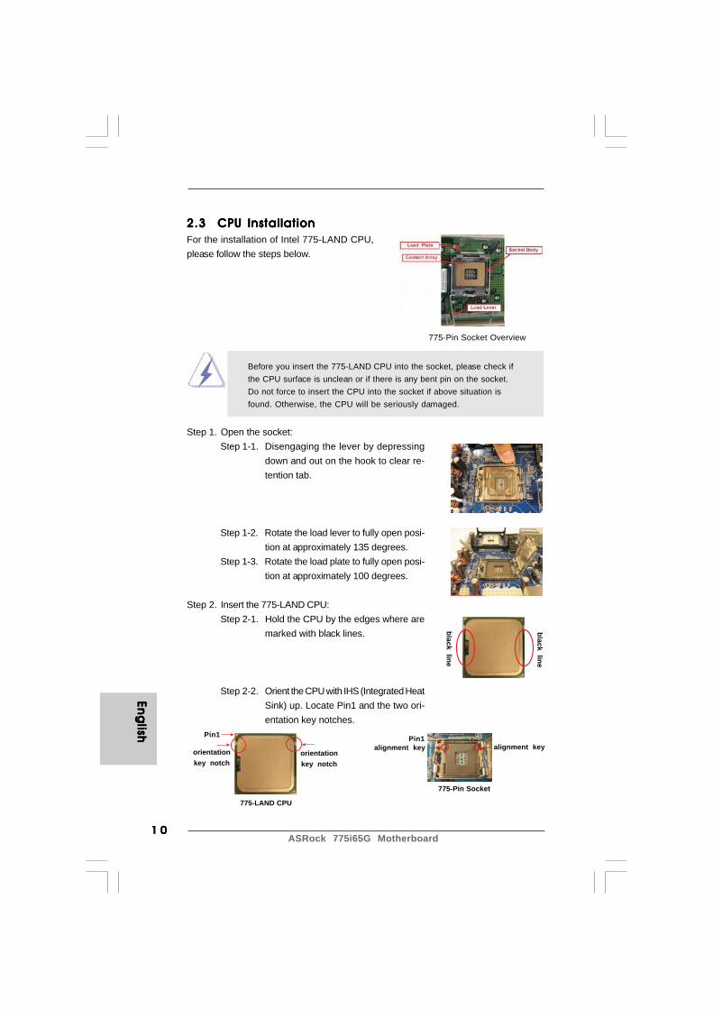
2.3 CPU Installation2.3 CPU Installation2.3 CPU Installation2.3 CPU Installation2.3 CPU InstallationFor the installation of Intel 775-LAND CPU,please follow the steps below.
Before you insert the 775-LAND CPU into the socket, please check ifthe CPU surface is unclean or if there is any bent pin on the socket.Do not force to insert the CPU into the socket if above situation isfound. Otherwise, the CPU will be seriously damaged.
Step 1. Open the socket:Step 1-1. Disengaging the lever by depressing
down and out on the hook to clear re-tention tab.
Step 1-2. Rotate the load lever to fully open posi-tion at approximately 135 degrees.
Step 1-3. Rotate the load plate to fully open posi-tion at approximately 100 degrees.
Step 2. Insert the 775-LAND CPU:Step 2-1. Hold the CPU by the edges where are
marked with black lines.
Step 2-2. Orient the CPU with IHS (Integrated HeatSink) up. Locate Pin1 and the two ori-entation key notches.
775-Pin Socket Overview
black line
black line
775-Pin Socket
Pin1alignment key alignment key
Pin1
orientationkey notch
orientationkey notch
775-LAND CPU

1 11 11 11 11 1ASRock 775i65G Motherboard
Eng
lish
Eng
lish
Eng
lish
Eng
lish
Eng
lish
For proper inserting, please ensure to match the two orientationkey notches of the CPU with the two alignment keys of thesocket.
Step 2-3. Carefully place the CPU into the socketby using a purely vertical motion.
Step 2-4. Verify that the CPU is within the socketand properly mated to the orient keys.
Step 3. Remove PnP Cap (Pick and Place Cap):Use your left hand index finger and thumb to sup-port the load plate edge, engage PnP cap with righthand thumb and peel the cap from the socket whilepressing on center of PnP cap to assist in removal.
1. It is recommended to use the cap tab to handle and avoid kicking off the PnP cap.2. This cap must be placed if returning the motherboard for after service.
Step 4. Close the socket:Step 4-1. Rotate the load plate onto the IHS.Step 4-2. While pressing down lightly on load
plate, engage the load lever.Step 4-3. Secure load lever with load plate tab
under retention tab of load lever.

ASRock 775i65G Motherboard1 21 21 21 21 2
Eng
lishEn
glish
Eng
lishEn
glish
Eng
lish
2 .42 .42 .42 .42 .4 Installation of CPU Fan and HeatsinkInstallation of CPU Fan and HeatsinkInstallation of CPU Fan and HeatsinkInstallation of CPU Fan and HeatsinkInstallation of CPU Fan and HeatsinkThis motherboard is equipped with 775-Pin socket that supports Intel 775-LAND CPU.Please adopt the type of heatsink and cooling fan compliant with Intel 775-LAND CPU todissipate heat. Before you installed the heatsink, you need to spray thermal interfacematerial between the CPU and the heatsink to improve heat dissipation. Ensure that theCPU and the heatsink are securely fastened and in good contact with each other. Thenconnect the CPU fan to the CPU_FAN connector (CPU_FAN1, see page 2, No. 4).For proper installation, please kindly refer to the instruction manuals of yourCPU fan and heatsink.
Below is an example to illustrate the installation of the heatsink for 775-LAND CPU.Step 1. Apply thermal interface material onto center of
IHS on the socket surface.
Step 2. Place the heatsink onto the socket. Ensure fancables are oriented on side closest to the CPUfan connector on the motherboard (CPU_FAN1,see page 2, No. 4).
Step 3. Align fasteners with the motherboardthroughholes.
Step 4. Rotate the fastener clockwise, then press downon fastener caps with thumb to install and lock.Repeat with remaining fasteners.
If you press down the fasteners without rotating them clockwise,the heatsink cannot be secured on the motherboard.
Step 5. Connect fan header with the CPU fan connectoron the motherboard.
Step 6. Secure excess cable with tie-wrap to ensurecable does not interfere with fan operation orcontact other components.
1 31 31 31 31 3ASRock 775i65G Motherboard
Eng
lish
Eng
lish
Eng
lish
Eng
lish
Eng
lish
notch
break
notch
break
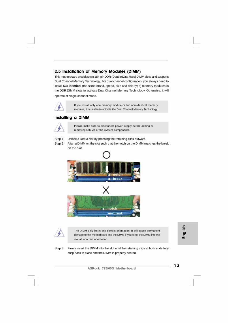
2.5 Installation of Memor2.5 Installation of Memor2.5 Installation of Memor2.5 Installation of Memor2.5 Installation of Memory Modules (DIMM)y Modules (DIMM)y Modules (DIMM)y Modules (DIMM)y Modules (DIMM)This motherboard provides two 184-pin DDR (Double Data Rate) DIMM slots, and supportsDual Channel Memory Technology. For dual channel configuration, you always need toinstall two identical (the same brand, speed, size and chip-type) memory modules inthe DDR DIMM slots to activate Dual Channel Memory Technology. Otherwise, it will
operate at single channel mode.
If you install only one memory module or two non-identical memorymodules, it is unable to activate the Dual Channel Memory Technology.
Installing a DIMMInstalling a DIMMInstalling a DIMMInstalling a DIMMInstalling a DIMM
Please make sure to disconnect power supply before adding orremoving DIMMs or the system components.
Step 1. Unlock a DIMM slot by pressing the retaining clips outward.Step 2. Align a DIMM on the slot such that the notch on the DIMM matches the break
on the slot.
The DIMM only fits in one correct orientation. It will cause permanentdamage to the motherboard and the DIMM if you force the DIMM into theslot at incorrect orientation.
Step 3. Firmly insert the DIMM into the slot until the retaining clips at both ends fullysnap back in place and the DIMM is properly seated.
ASRock 775i65G Motherboard1 41 41 41 41 4
Eng
lishEn
glish
Eng
lishEn
glish
Eng
lish
2.6 Expansion Slots (PCI and AGPSlots)2.6 Expansion Slots (PCI and AGPSlots)2.6 Expansion Slots (PCI and AGPSlots)2.6 Expansion Slots (PCI and AGPSlots)2.6 Expansion Slots (PCI and AGPSlots)There are 3 PCI slots and 1 AGP slot on this motherboard.PCI slots: The PCI slots are used to install expansion cards that have the 32-bit
PCI interface.AGP slot: The AGP slot is used to install a graphics card. The ASRock AGP slot has
a special design of clasp that can securely fasten the inserted graphicscard.
Do NOT use a 3.3V AGP card on the AGP slot of this motherboard!It may cause permanent damage!
Installing an expansion cardInstalling an expansion cardInstalling an expansion cardInstalling an expansion cardInstalling an expansion cardStep 1. Before installing the expansion card, please make sure that the power
supply is switched off or the power cord is unplugged. Please read thedocumentation of the expansion card and make necessary hardwaresettings for the card before you start the installation.
Step 2. Remove the system unit cover (if your motherboard is already installed in achassis).
Step 3. Remove the bracket facing the slot that you intend to use. Keep the screwsfor later use.
Step 4. Align the card connector with the slot and press firmly until the card iscompletely seated on the slot.
Step 5. Fasten the card to the chassis with screws.Step 6. Replace the system cover.

1 51 51 51 51 5ASRock 775i65G Motherboard
Eng
lish
Eng
lish
Eng
lish
Eng
lish
Eng
lish
JR1 JL1
2.7 Jumpers Setup2.7 Jumpers Setup2.7 Jumpers Setup2.7 Jumpers Setup2.7 Jumpers SetupThe illustration shows how jumpers are setup.When the jumper cap is placed onpins, the jumper is “Short”. If no jumper cap isplaced on pins, the jumper is “Open”. The il-lustration shows a 3-pin jumper whose pin1and pin2 are “Short” when jumper cap is placedon these 2 pins.
Jumper Setting DescriptionJR1 (see p.2 No. 22)
JL1 (see p.2 No. 22)
Note: If the jumpers JL1 and JR1 are short, both the front panel and the rear panelaudio connectors can work.
Clear CMOS Jumper(CLRCMOS0)
(see p.2 No. 15)
Note: CLRCMOS0 allows you to clear the data in CMOS. The data in CMOS includessystem setup information such as system password, date, time, and systemsetup parameters. To clear and reset the system parameters to default setup,please turn off the computer and unplug the power cord from the power supply.After waiting for 15 seconds, use a jumper cap to short pin2 and pin3 on CLRCMOS0for 5 seconds. However, please do not clear the CMOS right after you update theBIOS. If you need to clear the CMOS when you just finish updating the BIOS, youmust boot up the system first, and then shut it down before you do the clear-CMOS action.
Clear CMOS
2_31_2
Default
ASRock 775i65G Motherboard1 61 61 61 61 6
Eng
lishEn
glish
Eng
lishEn
glish
Eng
lish
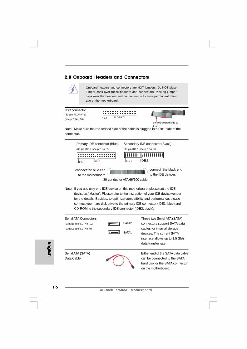
2.8 Onboard Headers and Connectors2.8 Onboard Headers and Connectors2.8 Onboard Headers and Connectors2.8 Onboard Headers and Connectors2.8 Onboard Headers and Connectors
Onboard headers and connectors are NOT jumpers. Do NOT placejumper caps over these headers and connectors. Placing jumpercaps over the headers and connectors will cause permanent dam-age of the motherboard!
FDD connector(33-pin FLOPPY1)
(see p.2 No. 18)
Note: Make sure the red-striped side of the cable is plugged into Pin1 side of theconnector.
Primary IDE connector (Blue) Secondary IDE connector (Black)(39-pin IDE1, see p.2 No. 7) (39-pin IDE2, see p.2 No. 6)
Note: If you use only one IDE device on this motherboard, please set the IDEdevice as “Master”. Please refer to the instruction of your IDE device vendorfor the details. Besides, to optimize compatibility and performance, pleaseconnect your hard disk drive to the primary IDE connector (IDE1, blue) andCD-ROM to the secondary IDE connector (IDE2, black).
Serial ATA Connectors These two Serial ATA (SATA)(SATA1: see p.2 No. 10) connectors support SATA data(SATA2: see p.2 No. 9) cables for internal storage
devices. The current SATAinterface allows up to 1.5 Gb/sdata transfer rate.
Serial ATA (SATA) Either end of the SATA data cableData Cable can be connected to the SATA
hard disk or the SATA connectoron the motherboard.
FLOPPY1Pin1
IDE1PIN1IDE2PIN1
the red-striped side toPin1
connect the black endto the IDE devices
connect the blue endto the motherboard
80-conductor ATA 66/100 cable
SATA2
SATA1

1 71 71 71 71 7ASRock 775i65G Motherboard
Eng
lish
Eng
lish
Eng
lish
Eng
lish
Eng
lish
USB_PWR
USB_PWR
P+7P-7
P+6P-6
GND
GND
DUMMY
1
USB_PWR
1
P-5
GND
DUMMY
USB_PWR
P+5
GND
P-4
P+4
1
IRTX
IRRXGND
+5VSBDUMMY
GND
AUD-OUT-L
1
BACKOUT-R
GND
AUD-OUT-RMIC-POWER
MIC
BACKOUT-L
USB 2.0 Header The I/O panel accommodates(9-pin USB67) 6 default USB 2.0 ports. If those(see p.2 No. 16) USB 2.0 ports on the I/O panel
are not sufficient, this USB 2.0header is available to support 2additional USB 2.0 ports.
Shared USB 2.0 Header This USB4_5 connector is shared(9-pin USB4_5) with the USB 2.0 ports 4,5 on(see p.2 No. 26) the I/O panel. When using the front
panel USB ports by attaching thefront panel USB cable to thisconnector (USB4_5), the USBports 4,5 on the I/O panel will notbe able to function.
Infrared Module Header This header supports an(5-pin IR1) optional wireless transmitting(see p.2 No. 17) and receiving infrared module.
Internal Audio Connectors These connectors allow you(4-pin CD1, 4-pin AUX1) to receive stereo audio input(CD1: see p.2 No. 19) from sound sources such as(AUX1: see p.2 No. 20) a CD-ROM, DVD-ROM, TV
tuner card, or MPEG card.
Front Panel AC’97 Audio Header This is an interface for front(8-pin AUDIO1) panel audio cable that allows(see p.2 No. 21) convenient connection and
control of audio devices.
CD
-L
GN
DG
ND
CD
-R
AU
X-L
GN
DG
ND
AU
X-R
CD1AUX1

ASRock 775i65G Motherboard1 81 81 81 81 8
Eng
lishEn
glish
Eng
lishEn
glish
Eng
lishGND
+12VCHA_FAN_SPEED
+5V
DUMMYDUMMY
SPEAKER
1
GND
PWRBTN#PLED-
PLED+
DUMMYRESET#
GND
HDLED+HDLED-
1
1. +5VA is used for audio power only, please don’t connect it to any other power, such as USB.
2. HD (Azalia) audio front panel and AC’97 audio front panel have different pin-definition. Incorrect connection of the audio front panel and the front panel audio header may cause permanent damage to this motherboard.
GND
+12V
CPU_FAN_SPEED
FAN_SPEED_CONTROL
System Panel Header This header accommodates(9-pin PANEL1) several system front panel(see p.2 No. 12) functions.
Chassis Speaker Header Please connect the chassis(4-pin SPEAKER 1) speaker to this header.(see p.2 No. 14)
Power LED Header Please connect the chassis power(3-pin PLED1) LED to this header to indicate(see p.2 No. 13) system power status. The LED is
on when the system is operating.The LED keeps blinking in S1state. The LED is off in S4state or S5 state (power off).
Chassis Fan Connector Please connect a chassis fan(3-pin CHA_FAN1) cable to this connector and(see p.2 No. 11) match the black wire to the
ground pin.
CPU Fan Connector Please connect a CPU fan cable(4-pin CPU_FAN1) to this connector and match(see p.2 No. 4) the black wire to the ground pin.
ATX Power Connector Please connect an ATX power(20-pin ATXPWR1) supply to this connector.(see p.2 No. 27)
1
PLED+
PLED+
PLED-
1 91 91 91 91 9ASRock 775i65G Motherboard
Eng
lish
Eng
lish
Eng
lish
Eng
lish
Eng
lish
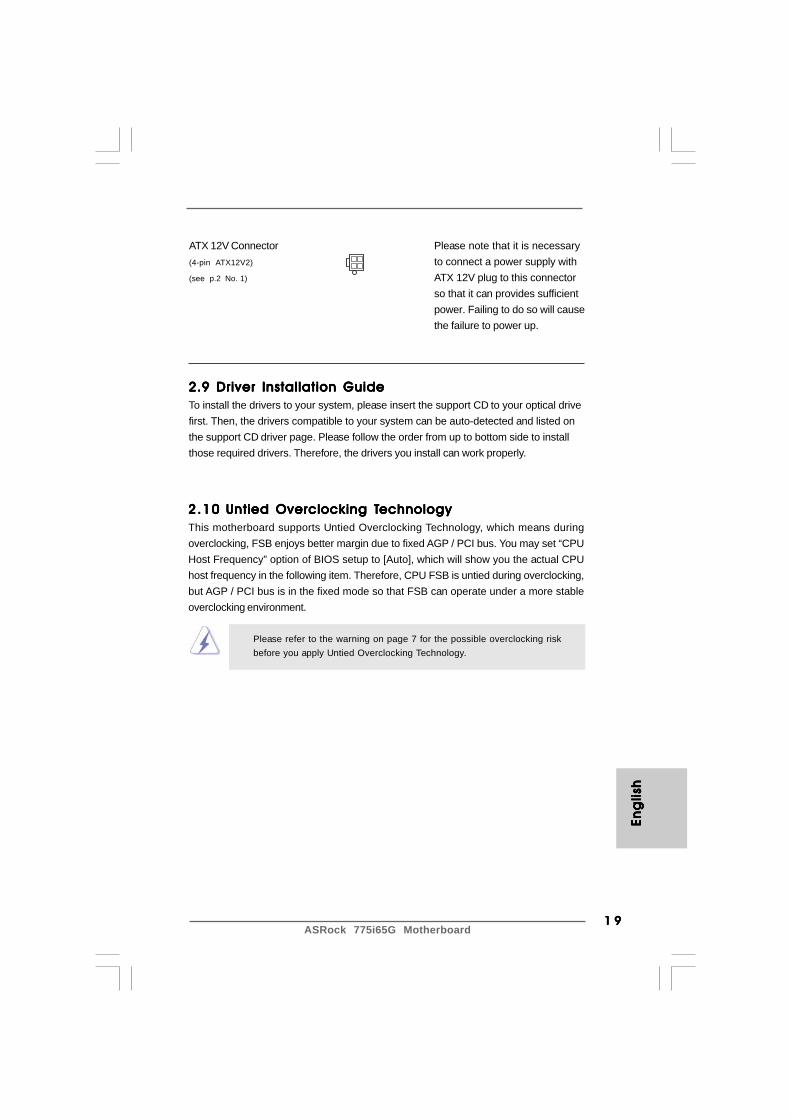
ATX 12V Connector Please note that it is necessary(4-pin ATX12V2) to connect a power supply with(see p.2 No. 1) ATX 12V plug to this connector
so that it can provides sufficientpower. Failing to do so will causethe failure to power up.
2.102.102.102.102.10 Untied Overclocking TUntied Overclocking TUntied Overclocking TUntied Overclocking TUntied Overclocking TechnologyechnologyechnologyechnologyechnologyThis motherboard supports Untied Overclocking Technology, which means duringoverclocking, FSB enjoys better margin due to fixed AGP / PCI bus. You may set “CPUHost Frequency” option of BIOS setup to [Auto], which will show you the actual CPUhost frequency in the following item. Therefore, CPU FSB is untied during overclocking,but AGP / PCI bus is in the fixed mode so that FSB can operate under a more stableoverclocking environment.
Please refer to the warning on page 7 for the possible overclocking riskbefore you apply Untied Overclocking Technology.
2.9 Driver Installation Guide2.9 Driver Installation Guide2.9 Driver Installation Guide2.9 Driver Installation Guide2.9 Driver Installation GuideTo install the drivers to your system, please insert the support CD to your optical drivefirst. Then, the drivers compatible to your system can be auto-detected and listed onthe support CD driver page. Please follow the order from up to bottom side to installthose required drivers. Therefore, the drivers you install can work properly.
ASRock 775i65G Motherboard2 02 02 02 02 0
Eng
lishEn
glish
Eng
lishEn
glish
Eng
lish
3. BIOS Information3. BIOS Information3. BIOS Information3. BIOS Information3. BIOS InformationThe Flash Memory on the motherboard stores BIOS Setup Utility. When you start upthe computer, please press <F2> during the Power-On-Self-Test (POST) to enterBIOS Setup utility; otherwise, POST continues with its test routines. If you wish toenter BIOS Setup after POST, please restart the system by pressing <Ctl> + <Alt> +<Delete>, or pressing the reset button on the system chassis.The BIOS Setup program is designed to be user-friendly. It is a menu-driven program,which allows you to scroll through its various sub-menus and to select among thepredetermined choices. For the detailed information about BIOS Setup, please referto the User Manual (PDF file) contained in the Support CD.
4. Sof4. Sof4. Sof4. Sof4. Software Supportware Supportware Supportware Supportware Support CD informationt CD informationt CD informationt CD informationt CD informationThis motherboard supports various Microsoft® Windows® operating systems: 98SE / ME/ 2000 / XP. The Support CD that came with the motherboard contains necessary driversand useful utilities that will enhance motherboard features.To begin using the Support CD, insert the CD into your CD-ROM drive. It will displaythe Main Menu automatically if “AUTORUN” is enabled in your computer. If the MainMenu does not appear automatically, locate and double-click on the file“ASSETUP.EXE” from the BIN folder in the Support CD to display the menus.

2 12 12 12 12 1ASRock 775i65G Motherboard
1. Einführung1. Einführung1. Einführung1. Einführung1. EinführungWir danken Ihnen für den Kauf des ASRock 775i65G Motherboard, ein zuverlässigesProdukt, welches unter den ständigen, strengen Qualitätskontrollen von ASRockgefertigt wurde. Es bietet Ihnen exzellente Leistung und robustes Design, gemäß derVerpflichtung von ASRock zu Qualität und Halbarkeit.Diese Schnellinstallationsanleitung führt in das Motherboard und die schrittweiseInstallation ein. Details über das Motherboard finden Sie in der Bedienungsanleitungauf der Support-CD.
Da sich Motherboard-Spezifikationen und BIOS-Software verändernkönnen, kann der Inhalt dieses Handbuches ebenfalls jederzeit geändertwerden. Für den Fall, dass sich Änderungen an diesem Handbuchergeben, wird eine neue Version auf der ASRock-Website, ohne weitereAnkündigung, verfügbar sein. Die neuesten Grafikkarten und unterstütztenCPUs sind auch auf der ASRock-Website aufgelistet.ASRock-Website: http://www.asrock.comWenn Sie technische Unterstützung zu Ihrem Motherboard oder spezifischeInformationen zu Ihrem Modell benötigen, besuchen Sie bitte unsereWebseite:www.asrock.com/support/index.asp
1.1 KartoninhaltASRock 775i65G Motherboard
(Micro ATX-Formfaktor: 24.4 cm x 20.3 cm; 9.6 Zoll x 8.0 Zoll)ASRock 775i65G SchnellinstallationsanleitungASRock 775i65G Support-CDEin 80-adriges Ultra-ATA 66/100 IDE-FlachbandkabelEin Seriell-ATA- (SATA) Datenkabel (Option)Ein Seriell-ATA (SATA) Festplattennetzkabel (Option)Ein I/O Shield
De
uts
ch
De
uts
ch
De
uts
ch
De
uts
ch
De
uts
ch

ASRock 775i65G Motherboard2 22 22 22 22 2
De
utsc
hD
eu
tsch
De
utsc
hD
eu
tsch
De
utsc
h
1 .21 .21 .21 .21 .2 Spezif ikationenSpezif ikationenSpezif ikationenSpezif ikationenSpezif ikationen
Plattform - Micro ATX-Formfaktor: 24.4 cm x 20.3 cm; 9.6 Zoll x 8.0 Zoll CPU - LGA 775 für Intel® Dual-Core CoreTM 2 Extreme / CoreTM 2 Duo
/ Pentium® D / Pentium® 4 / Celeron® D- FSB 1066 MHz für externe Grafik (siehe VORSICHT 1)- FSB 800/533 MHz für interne Grafik- Unterstützt Hyper-Threading-Technologie (siehe VORSICHT 2)- Unterstützt Untied-Übertaktungstechnologie (siehe VORSICHT 3)- Unterstützt EM64T-CPU
Chipsatz - Northbridge: Intel® 865G- Southbridge: Intel® ICH5
Speicher - Unterstützung von Dual-Kanal-DDR-Speichertechnologie (siehe VORSICHT 4)- 2 x Steckplätze für DDR- Unterstützt DDR400/333/266 (siehe VORSICHT 5)- Max. 2GB
Erweiterungs- - 3 x PCI -Steckplätze steckplätze - 1x AGP -Steckplätze, unterstützt 1.5V, 8X/4X AGP-Karten
(siehe VORSICHT 6) Onboard-VGA - Integrated Intel® Extreme Graphics 2
- DirectX 8.0 VGA- Maximal gemeinsam genutzter Speicher 96 MB- Unterstützt D-Sub mit einer maximalen Auflösung von 2048 x 1536 bei 75 Hz
Audio - 5.1 CH Audio (C-Media 9761A Audio Codec) LAN - Realtek PCI LAN 8101L
- Speed: 10/100 Ethernet- Unterstützt Wake-On-LAN- Unterstützt PXE
E/A-Anschlüsse I/O Panel an der - 1 x PS/2 Mouse Port Rückseite - 1 x PS/2 Keyboard Port
- 1 x Serieller port: COM 1- 1 x VGA Port- 1 x Parallel Port (ECP/EPP Support)- 6 x Ready-to-Use USB 2.0 Ports- 1 x RJ-45 LAN Port mit LED (SPEED LED)- Audioanschlüsse: Line In / Line Out / Mikrofon
2 32 32 32 32 3ASRock 775i65G Motherboard
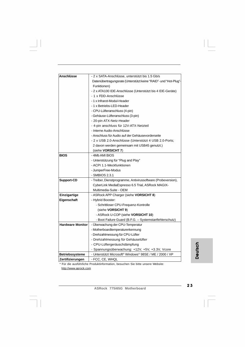
Anschlüsse - 2 x SATA-Anschlüsse, unterstützt bis 1.5 Gb/s Datenübertragungsrate (Unterstützt keine “RAID”- und “Hot-Plug”- Funktionen)- 2 x ATA100 IDE-Anschlüsse (Unterstützt bis 4 IDE-Geräte)- 1 x FDD-Anschlüsse- 1 x Infrarot-Modul-Header- 1 x Betriebs-LED-Header- CPU-Lüfteranschluss (4-pin)- Gehäuse-Lüfteranschluss (3-pin)- 20-pin ATX-Netz-Header- 4-pin anschluss für 12V-ATX-Netzteil- Interne Audio-Anschlüsse- Anschluss für Audio auf der Gehäusevorderseite- 2 x USB 2.0-Anschlüsse (Unterstützt 4 USB 2.0-Ports; 2 davon werden gemeinsam mit USB45 genutzt.) (siehe VORSICHT 7)
BIOS - 4Mb AMI BIOS- Unterstützung für “Plug and Play”- ACPI 1.1-Weckfunktionen- JumperFree-Modus- SMBIOS 2.3.1
Support-CD - Treiber, Dienstprogramme, Antivirussoftware (Probeversion), CyberLink MediaEspresso 6.5 Trial, ASRock MAGIX- Multimedia-Suite - OEM
Einzigartige - ASRock APP Charger (siehe VORSICHT 8) Eigenschaft - Hybrid Booster:
- Schrittloser CPU-Frequenz-Kontrolle (siehe VORSICHT 9)- ASRock U-COP (siehe VORSICHT 10)- Boot Failure Guard (B.F.G. – Systemstartfehlerschutz)
Hardware Monitor - Überwachung der CPU-Temperatur- Motherboardtemperaturerkennung- Drehzahlmessung für CPU-Lüfter- Drehzahlmessung für Gehäuselüfter- CPU-Lüftergeräuschdämpfung- Spannungsüberwachung: +12V, +5V, +3.3V, Vcore
Betriebssysteme - Unterstützt Microsoft® Windows® 98SE / ME / 2000 / XP Zertifizierungen - FCC, CE, WHQL * Für die ausführliche Produktinformation, besuchen Sie bitte unsere Website: http://www.asrock.com
De
uts
ch
De
uts
ch
De
uts
ch
De
uts
ch
De
uts
ch
ASRock 775i65G Motherboard2 42 42 42 42 4
De
utsc
hD
eu
tsch
De
utsc
hD
eu
tsch
De
utsc
h
VORSICHT!1. Die FSB1066-CPU wird nur unterstützt, wenn Sie eine AGP-VGA-Karte
im AGP-Steckplatz installieren. Wenn Sie allerdings eine FSB1066-CPUmit diesem Motherboard verwenden, nutzen Sie bitte ein DDR400 CL2.5-Speichermodul.
2. Die Einstellung der “Hyper-Threading Technology”, finden Sie aufSeite 29 des auf der Support-CD enthaltenen Benutzerhandbuchesbeschrieben.
3. Dieses Motherboard unterstützt die Untied-Übertaktungstechnologie.Unter “Entkoppelte Übertaktungstechnologie” auf Seite 19 finden Siedetaillierte Informationen.
4. Dieses Motherboard unterstützt Dual-Kanal-Speichertechnologie. VorImplementierung der Dual-Kanal-Speichertechnologie müssen Sie dieInstallationsanleitung für die Speichermodule auf Seite 13 zwecksrichtigerInstallation gelesen haben.
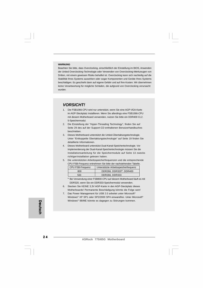
5. Die unterstützten Arbeitsspeicherfrequenzen und die entsprechendeCPU FSB-Frequenz entnehmen Sie bitte der nachstehenden Tabelle.
CPU FSB-Frequenz Unterstützte Arbeitsspeicherfrequenz 800 DDR266, DDR320*, DDR400533 DDR266, DDR333
* Bei Verwendung einer FSB800-CPU auf diesem Motherboard läuft es mitDDR320, wenn Sie ein DDR333-Speichermodul verwenden.
6. Stecken Sie KEINE 3,3V AGP-Karte in den AGP-Steckplatz diesesMotherboards! Permanente Beschädigung könnte die Folge sein!
7. Das Power Management für USB 2.0 arbeitet unter Microsoft®
Windows® XP SP1 oder SP2/2000 SP4 einwandfrei. Unter Microsoft®
Windows® 98/ME könnte es dagegen zu Störungen kommen.
WARNUNGBeachten Sie bitte, dass Overclocking, einschließlich der Einstellung im BIOS, Anwendender Untied Overclocking-Technologie oder Verwenden von Overclocking-Werkzeugen vonDritten, mit einem gewissen Risiko behaftet ist. Overclocking kann sich nachteilig auf dieStabilität Ihres Systems auswirken oder sogar Komponenten und Geräte Ihres Systemsbeschädigen. Es geschieht dann auf eigene Gefahr und auf Ihre Kosten. Wir übernehmenkeine Verantwortung für mögliche Schäden, die aufgrund von Overclocking verursachtwurden.

2 52 52 52 52 5ASRock 775i65G Motherboard
De
uts
ch
De
uts
ch
De
uts
ch
De
uts
ch
De
uts
ch
8. Wenn Sie nach einer schnelleren, weniger eingeschränktenMöglichkeit zur Aufladung Ihrer Apple-Geräte (z. B. iPhone/iPad/iPodtouch) suchen, bietet ASRock Ihnen eine wunderbare Lösung – denASRock APP Charger. Installieren Sie einfach den ASRock APPCharger-Treiber; dadurch lädt sich Ihr iPhone wesentlich schnellerüber einen Computer auf – genaugenommen bis zu 40 % schnellerals zuvor. Der ASRock APP Charger ermöglicht Ihnen die schnelleAufladung mehrerer Apple-Geräte gleichzeitig; der Ladevorgang wirdsogar dann fortgesetzt, wenn der PC den Ruhezustand (S1) oderTiefschlafmodus (S4) aufruft oder ausgeschaltet wird (S5). Nach derInstallation des APP Charger-Treibers können Sie im Handumdrehendas großartigste Ladeerlebnis überhaupt genießen.ASRock-Webseite: http://www.asrock.com/Feature/AppCharger/index.asp
9. Obwohl dieses Motherboard stufenlose Steuerung bietet, wirdOverclocking nicht empfohlen. Frequenzen, die von den empfohlenenCPU-Busfrequenzen abweichen, können Instabilität des Systemsverursachen oder die CPU beschädigen.
10. Wird eine Überhitzung der CPU registriert, führt das System einenautomatischen Shutdown durch. Bevor Sie das System neu starten,prüfen Sie bitte, ob der CPU-Lüfter am Motherboard richtig funktioniert,und stecken Sie bitte den Stromkabelstecker aus und dann wieder ein.Um die Wärmeableitung zu verbessern, bitte nicht vergessen, etwasWärmeleitpaste zwischen CPU und Kühlkörper zu sprühen.
ASRock 775i65G Motherboard2 62 62 62 62 6
De
utsc
hD
eu
tsch
De
utsc
hD
eu
tsch
De
utsc
h
Gebrückt Offen
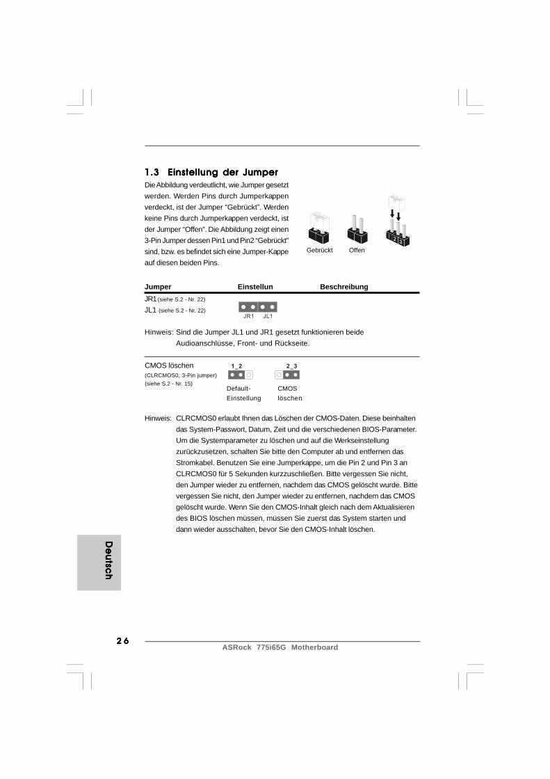
1.3 Einstellung der Jumper1.3 Einstellung der Jumper1.3 Einstellung der Jumper1.3 Einstellung der Jumper1.3 Einstellung der JumperDie Abbildung verdeutlicht, wie Jumper gesetztwerden. Werden Pins durch Jumperkappenverdeckt, ist der Jumper “Gebrückt”. Werdenkeine Pins durch Jumperkappen verdeckt, istder Jumper “Offen”. Die Abbildung zeigt einen3-Pin Jumper dessen Pin1 und Pin2 “Gebrückt”sind, bzw. es befindet sich eine Jumper-Kappeauf diesen beiden Pins.
Jumper Einstellun BeschreibungJR1(siehe S.2 - Nr. 22)
JL1 (siehe S.2 - Nr. 22)
Hinweis: Sind die Jumper JL1 und JR1 gesetzt funktionieren beideAudioanschlüsse, Front- und Rückseite.
CMOS löschen(CLRCMOS0, 3-Pin jumper)(siehe S.2 - Nr. 15)
Hinweis: CLRCMOS0 erlaubt Ihnen das Löschen der CMOS-Daten. Diese beinhaltendas System-Passwort, Datum, Zeit und die verschiedenen BIOS-Parameter.Um die Systemparameter zu löschen und auf die Werkseinstellungzurückzusetzen, schalten Sie bitte den Computer ab und entfernen dasStromkabel. Benutzen Sie eine Jumperkappe, um die Pin 2 und Pin 3 anCLRCMOS0 für 5 Sekunden kurzzuschließen. Bitte vergessen Sie nicht,den Jumper wieder zu entfernen, nachdem das CMOS gelöscht wurde. Bittevergessen Sie nicht, den Jumper wieder zu entfernen, nachdem das CMOSgelöscht wurde. Wenn Sie den CMOS-Inhalt gleich nach dem Aktualisierendes BIOS löschen müssen, müssen Sie zuerst das System starten unddann wieder ausschalten, bevor Sie den CMOS-Inhalt löschen.
JR1 JL1
2_31_2
CMOSlöschen
Default-Einstellung
2 72 72 72 72 7ASRock 775i65G Motherboard
IDE1PIN1IDE2PIN1
FLOPPY1Pin1
De
uts
ch
De
uts
ch
De
uts
ch
De
uts
ch
De
uts
ch
1.4 Integrierte Header und Anschlüsse1.4 Integrierte Header und Anschlüsse1.4 Integrierte Header und Anschlüsse1.4 Integrierte Header und Anschlüsse1.4 Integrierte Header und Anschlüsse
Integrierte Header und Anschlüsse sind KEINE Jumper. Setzen Sie KEINEJumperkappen auf diese Header und Anschlüsse. Wenn Sie Jumperkappenauf Header und Anschlüsse setzen, wird das Motherboard unreparierbarbeschädigt!
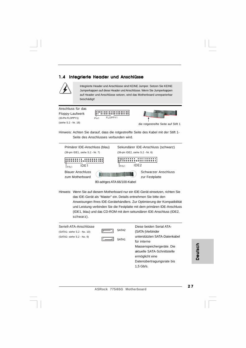
Anschluss für dasFloppy-Laufwerk(33-Pin FLOPPY1)
(siehe S.2 - Nr. 18)
Hinweis: Achten Sie darauf, dass die rotgestreifte Seite des Kabel mit der Stift 1-Seite des Anschlusses verbunden wird.
Primärer IDE-Anschluss (blau) Sekundärer IDE-Anschluss (schwarz)(39-pin IDE1, siehe S.2 - Nr. 7) (39-pin IDE2, siehe S.2 - Nr. 6)
Blauer Anschluss Schwarzer Anschlusszum Motherboard zur Festplatte
80-adriges ATA 66/100-Kabel
Hinweis: Wenn Sie auf diesem Motherboard nur ein IDE-Gerät einsetzen, richten Siedas IDE-Gerät als “Master” ein. Details entnehmen Sie bitte denAnweisungen Ihres IDE-Gerätehändlers. Zur Optimierung der Kompatibilitätund Leistung verbinden Sie die Festplatte mit dem primären IDE-Anschluss(IDE1, blau) und das CD-ROM mit dem sekundären IDE-Anschluss (IDE2,schwarz).
Seriell-ATA-Anschlüsse Diese beiden Serial ATA-(SATA1: siehe S.2 - No. 10) (SATA-)Verbínder(SATA2: siehe S.2 - No. 9) unterstützten SATA-Datenkabel
für interneMassenspeichergeräte. Dieaktuelle SATA-Schnittstelleermöglicht eineDatenübertragungsrate bis1,5 Gb/s.
die rotgestreifte Seite auf Stift 1
SATA2
SATA1

ASRock 775i65G Motherboard2 82 82 82 82 8
De
utsc
hD
eu
tsch
De
utsc
hD
eu
tsch
De
utsc
h
Serial ATA- (SATA-) Sie können beide Enden desDatenkabel SATA-Datenkabels entweder mit(Option) der SATA-Festplatte oder dem
SATA-Anschluss am Mainboardverbinden.
USB 2.0-Header E/A-Anschlüsse an der Rückseite(9-pin USB67) besitzt 6 Standard-USB 2.0-(siehe S.2 - No. 16) Anschlüsse auf der Rückseite.
Wenn die hinteren USB-Anschlüsse nicht ausreichen,steht dieser USB 2.0-Header(USB67) zur Unterstützung von 2zusätzlichen USB 2.0-Anschlüssen zur Verfügung.
Gemeinsam genutzter Dieser USB4_5-Header wird mitUSB 2.0-Header den USB 2.0-Anschlüssen 4,5(9-pin USB4_5) auf E/A-Anschlüsse an der(siehe S.2 - No. 26) Rückseite gemeinsam genutzt. Bei
Verwendung der vorderseitigenUSB-Anschlüsse durchVerbinden des vorseitigen USB-Kabels mit diesem Header(USB4_5) werden die USB-Anschlüsse 4,5 auf E/A-Anschlüsse an der Rückseite nichtfunktionieren.
Anschluss für Dieser Anschluss unterstütztInfrarot-Modul einen optionalen Infrarot-(5-Pin IR1) Sender/Empfänger.(siehe S.2 - No. 17)
USB_PWR
USB_PWR
P+7P-7
P+6P-6
GND
GND
DUMMY
1
USB_PWR
1
P-5
GND
DUMMY
USB_PWR
P+5
GND
P-4
P+4
1
IRTX
IRRXGND
+5VSBDUMMY
2 92 92 92 92 9ASRock 775i65G Motherboard
GND
AUD-OUT-L
1
BACKOUT-R
GND
AUD-OUT-RMIC-POWER
MIC
BACKOUT-L
CD
-L
GN
D
GN
D
CD
-R
AU
X-L
GN
D
GN
D
AU
X-R
CD1AUX1
De
uts
ch
De
uts
ch
De
uts
ch
De
uts
ch
De
uts
ch
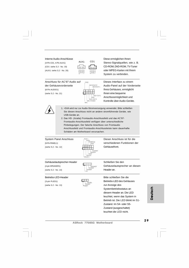
Interne Audio-Anschlüsse Diese ermöglichen Ihnen(4-Pin CD1, 4-Pin AUX1) Stereo-Signalquellen, wie z. B.(CD1: siehe S.2 - No. 19) CD-ROM, DVD-ROM, TV-Tuner(AUX1: siehe S.2 - No. 20) oder MPEG-Karten mit Ihrem
System zu verbinden.
Anschluss für AC’97 Audio auf Dieses Interface zu einemder Gehäusevorderseite Audio-Panel auf der Vorderseite(8-Pin AUDIO1) Ihres Gehäuses, ermöglicht(siehe S.2 - No. 21) Ihnen eine bequeme
Anschlussmöglichkeit undKontrolle über Audio-Geräte.
System Panel Anschluss Dieser Anschluss ist für die(9-Pin PANEL1) verschiedenen Funktionen der(siehe S.2 - No. 12) Gehäusefront.
Gehäuselautsprecher-Header Schließen Sie den(4-pin SPEAKER1) Gehäuselautsprecher an diesen(siehe S.2 - No. 14) Header an.
Betriebs-LED-Header Bitte schließen Sie die(3-pin PLED1) Betriebs-LED des Gehäuses(siehe S.2 - No. 13) zur Anzeige des
Systembetriebsstatus andiesem Header an. Die LEDleuchtet, wenn das System inBetrieb ist. Die LED blinkt im S1-Zustand. Im S4- oder S5-Zustand (ausgeschaltet)leuchtet die LED nicht.
1. +5VA wird nur zur Audio-Stromversorgung verwendet. Bitte schließen Sie diesen Anschluss nicht an andere stromführende Geräte, wie
USB-Geräte an.2. Das HD- (Azalia) Frontaudio-Anschlussfeld und das AC’97-
Frontaudio-Anschlussfeld verfügen über unterschiedliche Pinbelegungen. Der falsche Anschluss von Frontaudio Anschlussfeld und Frontaudio-Anschlussleiste kann dauerhafte Schäden am Motherboard verursachen.
+5V
DUMMYDUMMY
SPEAKER
1
GND
PWRBTN#PLED-
PLED+
DUMMYRESET#
GND
HDLED+HDLED-
1
1
PLED+
PLED+
PLED-
ASRock 775i65G Motherboard3 03 03 03 03 0
GND
+12VCHA_FAN_SPEED
GND
+12V
CPU_FAN_SPEED
FAN_SPEED_CONTROL
De
utsc
hD
eu
tsch
De
utsc
hD
eu
tsch
De
utsc
h
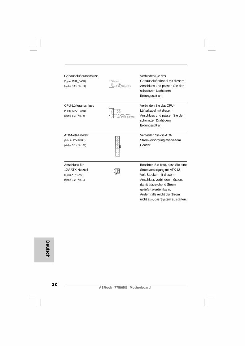
Gehäuselüfteranschluss Verbinden Sie das(3-pin CHA_FAN1) Gehäuselüfterkabel mit diesem(siehe S.2 - No. 11) Anschluss und passen Sie den
schwarzen Draht demErdungsstift an.
CPU-Lüfteranschluss Verbinden Sie das CPU -(4-pin CPU_FAN1) Lüfterkabel mit diesem(siehe S.2 - No. 4) Anschluss und passen Sie den
schwarzen Draht demErdungsstift an.
ATX-Netz-Header Verbinden Sie die ATX-(20-pin ATXPWR1) Stromversorgung mit diesem(siehe S.2 - No. 27) Header.
Anschluss für Beachten Sie bitte, dass Sie eine12V-ATX-Netzteil Stromversorgung mit ATX 12-(4-pin ATX12V2) Volt-Stecker mit diesem(siehe S.2 - No. 1) Anschluss verbinden müssen,
damit ausreichend Stromgeliefert werden kann.Andernfalls reicht der Stromnicht aus, das System zu starten.

3 13 13 13 13 1ASRock 775i65G Motherboard
De
uts
ch
De
uts
ch
De
uts
ch
De
uts
ch
De
uts
ch
2. BIOS-Information2. BIOS-Information2. BIOS-Information2. BIOS-Information2. BIOS-InformationDas Flash Memory dieses Motherboards speichert das Setup-Utility. Drücken Sie<F2> während des POST (Power-On-Self-Test) um ins Setup zu gelangen, ansonstenwerden die Testroutinen weiter abgearbeitet. Wenn Sie ins Setup gelangen wollen,nachdem der POST durchgeführt wurde, müssen Sie das System über dieTastenkombination <Ctrl> + <Alt> + <Delete> oder den Reset-Knopf auf derGehäusevorderseite, neu starten. Natürlich können Sie einen Neustart auchdurchführen, indem Sie das System kurz ab- und danach wieder anschalten.Das Setup-Programm ist für eine bequeme Bedienung entwickelt worden. Es istein menügesteuertes Programm, in dem Sie durch unterschiedliche Untermenüsscrollen und die vorab festgelegten Optionen auswählen können. Für detaillierteInformationen zum BIOS-Setup, siehe bitte das Benutzerhandbuch (PDF Datei) aufder Support CD.
3. Software Support CD information3. Software Support CD information3. Software Support CD information3. Software Support CD information3. Software Support CD informationDieses Motherboard unterstützt eine Reiche von Microsoft® Windows®
Betriebssystemen: 98SE / ME / 2000 / XP. Die Ihrem Motherboard beigefügteSupport-CD enthält hilfreiche Software, Treiber und Hilfsprogramme, mit denen Siedie Funktionen Ihres Motherboards verbessern können Legen Sie die Support-CDzunächst in Ihr CD-ROM-Laufwerk ein. Der Willkommensbildschirm mit denInstallationsmenüs der CD wird automatisch aufgerufen, wenn Sie die “Autorun”-Funktion Ihres Systems aktiviert haben.Erscheint der Wilkommensbildschirm nicht, so “doppelklicken” Sie bitte auf das FileASSETUP.EXE im BIN-Verzeichnis der Support-CD, um die Menüs aufzurufen.Das Setup-Programm soll es Ihnen so leicht wie möglich machen. Es ist menügesteuert,d.h. Sie können in den verschiedenen Untermenüs Ihre Auswahl treffen und dieProgramme werden dann automatisch installiert.

ASRock 775i65G Motherboard3 23 23 23 23 2
Fran
ça
isFra
nç
ais
Fran
ça
isFra
nç
ais
Fran
ça
is
1. Introduction1. Introduction1. Introduction1. Introduction1. IntroductionMerci pour votre achat d’une carte mère ASRock 775i65G, une carte mère très fiableproduite selon les critères de qualité rigoureux de ASRock. Elle offre des perfor-mances excellentes et une conception robuste conformément à l’engagementd’ASRock sur la qualité et la fiabilité au long terme.Ce Guide d’installation rapide présente la carte mère et constitue un guided’installation pas à pas. Des informations plus détaillées concernant la carte mèrepourront être trouvées dans le manuel l’utilisateur qui se trouve sur le CDd’assistance.
Les spécifications de la carte mère et le BIOS ayant pu être mis àjour, •le contenu de ce manuel est sujet à des changements sansnotification. Au cas où n’importe qu’elle modification intervenait sur cemanuel, la version mise à jour serait disponible sur le site webASRock sans nouvel avis. Vous trouverez les listes de prise encharge des cartes VGA et CPU également sur le site Web ASRock.Site web ASRock, http://www.asrock.comSi vous avez besoin de support technique en relation avec cette cartemère, veuillez consulter notre site Web pour de plus amplesinformations particulières au modèle que vous utilisez.www.asrock.com/support/index.asp
1.1 Contenu du paquetCarte mère ASRock 775i65G
(Facteur de forme Micro ATX : 9.6 pouces x 8.0 pouces, 24.4 cm x 20.3 cm)Guide d’installation rapide ASRock 775i65GCD de soutien ASRock 775i65GUn câble ruban IDE Ultra ATA 66/100 80 conducteursUn câble de données Serial ATA (SATA) (en option)Un écran I/O

3 33 33 33 33 3ASRock 775i65G Motherboard
1.21.21.21.21.2 SpécificationsSpécificationsSpécificationsSpécificationsSpécifications
Format - Facteur de forme Micro ATX:9.6 pouces x 8.0 pouces, 24.4 cm x 20.3 cm
CPU - LGA 775 pour Intel® double-coeur CoreTM 2 Extreme / CoreTM 2 Duo / Pentium® D / Pentium® 4 / Celeron® D- FSB 1066 MHz pour graphiques externes (voir ATTENTION 1)- FSB 800/533 MHz pour graphiques internes- Prise en charge de la technologie Hyper-Threading (voir ATTENTION 2)- Prend en charge la technologie Untied Overclocking (voir ATTENTION 3)- Prise en charge de la technologie EM64T par le CPU
Chipsets - Northbridge: Intel® 865G- Southbridge: Intel® ICH5
Mémoire - Compatible avec la Technologie de Mémoire à Canal Double(voir ATTENTION 4)
- 2 x slots DIMM DDR- Supporte DDR400/333/266 (voir ATTENTION 5)- Max. 2Go
Slot d’extension - 3 x slots PCI- 1 x slot AGP, support des cartes AGP 1.5V, 8X / 4X (voir ATTENTION 6)
VGA sur carte - Intel® Extreme Graphics 2 intégré- VGA DirectX 8.0- mémoire partagée max 96 MB- Prend en charge le D-Sub avec une résolution maximale jusqu’à 2048x1536 @ 75Hz
Audio - 5.1 Son de CH (codec audio C-Media 9761A) LAN - Realtek PCI LAN 8101L
- Vitesse: 10/100 Ethernet- Support du Wake-On-LAN- Supporte PXE
Panneau arrière I/O Panel E/S - 1 x port souris PS/2
- 1 x port clavier PS/2- 1 x port série: COM 1- 1 x port VGA- 1 x port parallèle: Support ECP/EPP- 1 x port LAN RJ-45 avec LED (LED VITESSE)
Fra
nFr
an
Fra
nFr
an
Fra
nç
ais
ça
isç
ais
ça
isç
ais

ASRock 775i65G Motherboard3 43 43 43 43 4
Fran
ça
isFra
nç
ais
Fran
ça
isFra
nç
ais
Fran
ça
is
- Jack audio: entrée ligne / sortie ligne / microphone Connecteurs - 2 connecteurs SATA, prennent en charge un taux de
transfert de données pouvant aller jusqu’à 1.5Go/s (Ne supporte pas les fonctions “RAID” et “Hot-Plug” (Connexion à chaud))- 2 x ATA100 IDE connecteurs (prend en charge jusqu’à 4 périphériques IDE)- 1 x Port Disquette- 1 x Connecteur module infrarouge- 1 x Connecteur de LED d’alimentation- Connecteur pour ventilateur de CPU (br. 4)- Connecteur pour ventilateur de Châssis (br. 3)- br. 20 connecteur d’alimentation ATX- br. 4 connecteur d’alimentation 12V ATX- Connecteurs audio internes- Connecteur audio panneau avant- 2 x En-tête USB 2.0 (Supporte 4 ports USB 2.0 ; 2 de ces ports sont partagés avec USB45) (voir ATTENTION 7)
BIOS - 4Mb BIOS AMI- Support du “Plug and Play”- Compatible pour événements de réveil ACPI 1.1- Gestion jumperless- Support SMBIOS 2.3.1
CD d’assistance - Pilotes, utilitaires, logiciel anti-virus (Version d’essai), CyberLink MediaEspresso 6.5 Trial,Suite multimédia ASRock MAGIX - OEM
Caractéristique - Chargeur ASRock APP (voir ATTENTION 8) unique - L’accélérateur hybride:
- Contrôle direct de la fréquence CPU (voir ATTENTION 9)- ASRock U-COP (voir ATTENTION 10)- Garde d’échec au démarrage (B.F.G.)
Surveillance - Contrôle de la température CPU système - Mesure de température de la carte mère
- Tachéomètre ventilateur CPU- Tachéomètre ventilateur châssis- Ventilateur silencieux d’unité centrale- Monitoring de la tension: +12V, +5V, +3.3V, Vcore
OS - Microsoft® Windows® 98SE / ME / 2000 / XP Certifications - FCC, CE, WHQL * Pour de plus amples informations sur les produits, s’il vous plaît visitez notre site web: http://www.asrock.com
3 53 53 53 53 5ASRock 775i65G Motherboard
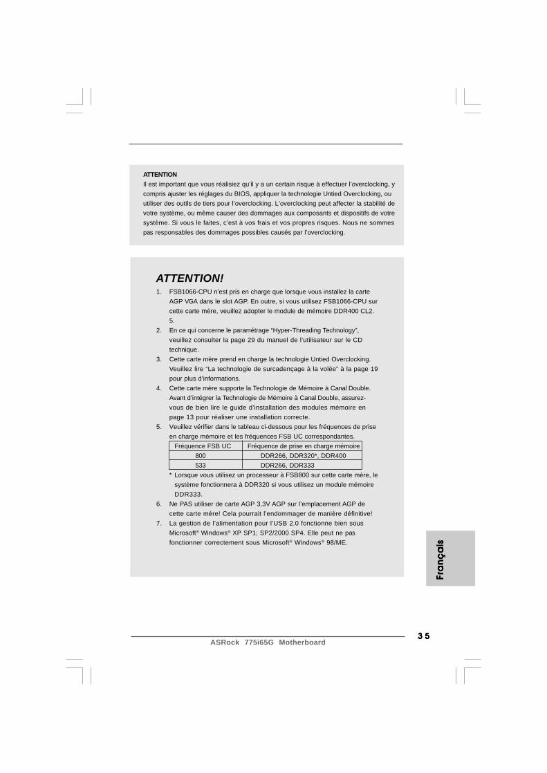
ATTENTION!1. FSB1066-CPU n’est pris en charge que lorsque vous installez la carte
AGP VGA dans le slot AGP. En outre, si vous utilisez FSB1066-CPU surcette carte mère, veuillez adopter le module de mémoire DDR400 CL2.5.
2. En ce qui concerne le paramétrage “Hyper-Threading Technology”,veuillez consulter la page 29 du manuel de l’utilisateur sur le CDtechnique.
3. Cette carte mère prend en charge la technologie Untied Overclocking.Veuillez lire “La technologie de surcadençage à la volée” à la page 19pour plus d’informations.
4. Cette carte mère supporte la Technologie de Mémoire à Canal Double.Avant d’intégrer la Technologie de Mémoire à Canal Double, assurez-vous de bien lire le guide d’installation des modules mémoire enpage 13 pour réaliser une installation correcte.
5. Veuillez vérifier dans le tableau ci-dessous pour les fréquences de priseen charge mémoire et les fréquences FSB UC correspondantes.
Fréquence FSB UC Fréquence de prise en charge mémoire800 DDR266, DDR320*, DDR400533 DDR266, DDR333
* Lorsque vous utilisez un processeur à FSB800 sur cette carte mère, lesystème fonctionnera à DDR320 si vous utilisez un module mémoireDDR333.
6. Ne PAS utiliser de carte AGP 3,3V AGP sur l’emplacement AGP decette carte mère! Cela pourrait l’endommager de manière définitive!
7. La gestion de l’alimentation pour l’USB 2.0 fonctionne bien sousMicrosoft® Windows® XP SP1; SP2/2000 SP4. Elle peut ne pasfonctionner correctement sous Microsoft® Windows® 98/ME.
ATTENTIONIl est important que vous réalisiez qu’il y a un certain risque à effectuer l’overclocking, ycompris ajuster les réglages du BIOS, appliquer la technologie Untied Overclocking, ouutiliser des outils de tiers pour l’overclocking. L’overclocking peut affecter la stabilité devotre système, ou même causer des dommages aux composants et dispositifs de votresystème. Si vous le faites, c’est à vos frais et vos propres risques. Nous ne sommespas responsables des dommages possibles causés par l’overclocking.
Fra
nFr
an
Fra
nFr
an
Fra
nç
ais
ça
isç
ais
ça
isç
ais
ASRock 775i65G Motherboard3 63 63 63 63 6
Fran
ça
isFra
nç
ais
Fran
ça
isFra
nç
ais
Fran
ça
is
8. Si vous désirez un moyen plus rapide et moins contraignant derecharger vos appareils Apple tels que iPhone/iPod/iPad Touch,ASRock a préparé pour vous la solution idéale - le chargeur ASRockAPP. Il suffit d’installer le pilote du chargeur APP, et vous pourrezrecharger rapidement votre iPhone à partir de votre ordinateur,jusqu’à 40% plus vite qu’avant. Le chargeur ASRock APP vous permetde charger rapidement et simultanément plusieurs appareils Apple,et le chargement continu est même pris en charge lorsque le PCpasse en mode Veille (S1), hibernation (S4) ou hors tension (S5).Lorsque le pilote du chargeur APP est installé, vous découvrez unmode de mise en charge tout à fait inédit.Site web ASRock : http://www.asrock.com/Feature/AppCharger/index.asp
9. Même si cette carte mère offre un contrôle sans souci, il n’est pasrecommandé d’y appliquer un over clocking. Les fréquences autresque les fréquences de bus d’UC recommandées risquent dedéstabiliser le système ou d’endommager l’UC.
10. Lorsqu’une surchauffe du CPU est détectée, le système s’arrêteautomatiquement. Avant de redémarrer le système, veuillez vérifierque le ventilateur d’UC sur la carte mère fonctionne correctement etdébranchez le cordon d’alimentation, puis rebranchez-le. Pouraméliorer la dissipation de la chaleur, n’oubliez pas de mettre de lapâte thermique entre le CPU le dissipateur lors de l’installation duPC.

3 73 73 73 73 7ASRock 775i65G Motherboard
1.3 Réglage des cavaliers1.3 Réglage des cavaliers1.3 Réglage des cavaliers1.3 Réglage des cavaliers1.3 Réglage des cavaliersL’illustration explique le réglage des cavaliers.Quand un capuchon est placé sur les broches,le cavalier est « FERME ». Si aucun capuchonne rel ie les broches, le caval ier est« OUVERT ». L’illustration montre un cavalierà 3 broches dont les broches 1 et 2 sont« FERMEES » quand le capuchon est placésur ces 2 broches.
Le Cavalier DescriptionJR1(voir p.2 No. 22)
JL1(voir p.2 No. 22)
Note: Si les cavaliers JL1 et JR1 sont reliés, les connecteurs audio du panneauavant et du panneau arrière peuvent fonctionner.
Effacer la CMOS(CLRCMOS0,le cavalier à 3 broches)(voir p.2 No. 15)
Note: CLRCMOS0 vous permet d’effacer les données qui se trouvent dans la CMOS.Les données dans la CMOS comprennent les informations de configuration dusystème telles que le mot de passe système, la date, l’heure et les paramètresde configuration du système. Pour effacer et réinitialiser les paramètres dusystème pour retrouver la configuration par défaut, veuillez mettre l’ordinateurhors tension et débrancher le cordon d’alimentation de l’alimentation électrique.Attendez 15 secondes, puis utilisez un capuchon de cavalier pour court-circuiter la broche 2 et la broche 3 sur CLRCMOS0 pendant 5 secondes. Aprèsavoir court-circuité le cavalier Effacer la CMOS, veuillez enlever le capuchon decavalier. Toutefois, veuillez ne pas effacer la CMOS tout de suite après avoir misle BIOS à jour. Si vous avez besoin d’effacer la CMOS lorsque vous avez fini demettre le BIOS à jour, vous devez d’abord initialiser le système, puis le mettrehors tension avant de procéder à l’opération d’effacement de la CMOS.
Ferme Ouvert
Fra
nFr
an
Fra
nFr
an
Fra
nç
ais
ça
isç
ais
ça
isç
ais
JR1 JL1
2_31_2
Effacer laCMOS
Paramètrespar défaut

ASRock 775i65G Motherboard3 83 83 83 83 8
FLOPPY1Pin1
IDE1PIN1 IDE2PIN1
SATA2
SATA1
Fran
ça
isFra
nç
ais
Fran
ça
isFra
nç
ais
Fran
ça
is
1.4 En-têtes et Connecteurs sur Carte1.4 En-têtes et Connecteurs sur Carte1.4 En-têtes et Connecteurs sur Carte1.4 En-têtes et Connecteurs sur Carte1.4 En-têtes et Connecteurs sur Carte
Les en-têtes et connecteurs sur carte NE SONT PAS des cavaliers.NE PAS placer les capuchons de cavalier sur ces en-têtes etconnecteurs. Le fait de placer les capuchons de cavalier sur les en-têtes et connecteurs causera à la carte mère des dommagesirréversibles!
Connecteur du lecteurde disquette(FLOPPY1 br. 33)(voir p.2 No. 18)
Note: Assurez-vous que le côté avec fil rouge du câble est bien branché sur lecôté Broche1 du connecteur.
Connecteur IDE primaire (bleu) Connecteur IDE secondaire (noir)(39-pin IDE1, voir p.2 No. 7) (39-pin IDE2, voir p.2 No. 6)
Connecteur bleu Connecteur noirvers la carte mère vers le disque dur
Câble ATA 66/100 80 conducteurs
Note: Si vous utilisez seulement un périphérique IDE sur cette carte mère, veuillezconfigurer le périphérique IDE comme “Maître”. Veuillez vous reporter auxinstructions du fabricant de votre IDE périphérique pour les détails. En outre,pour optimiser la compatibilité et les performances, veuillez connecter votreunité de disque dur sur le connecteur IDE principal (IDE1, bleu) et votre CD-ROM sur le connecteur IDE secondaire (IDE2, noir).
Connecteurs Série ATA Ces deux connecteurs Série(SATA1: voir p.2 No. 10) ATA (SATA) prennent en(SATA2: voir p.2 No. 9) charge les câbles SATA pour
les périphériques de stockageinternes. L’interface SATAactuelle permet des tauxtransferts de données pouvantaller jusqu’à 1,5 Go/s.
le côté avec fil rouge côté Broche1

3 93 93 93 93 9ASRock 775i65G Motherboard
USB_PWR
USB_PWR
P+7P-7
P+6P-6
GND
GND
DUMMY
1
USB_PWR
1
P-5
GND
DUMMY
USB_PWR
P+5
GND
P-4
P+4
1
IRTX
IRRXGND
+5VSBDUMMY
Câble de données L’une des deux extrémités duSérie ATA (SATA) câble de données SATA peut(en option) être connectée au disque dur
SATA ou au connecteur SATA surla carte mère.
En-tête USB 2.0 Panneau arrière E/S vous apporte(USB67 br.9) 6 ports USB 2.0 par défaut sur(voir p.2 No. 16) le panneau arrière. Si le nombre
des ports USB à l’arrière n’estpas suffisant, cette En-têteUSB 2.0 (USB67) permet deprendre en charge deux portsUSB 2.0 supplémentaires.
En-tête USB 2.0 partagé Cet en-tête USB4_5 est(USB4_5 br.9) partagé avec les ports USB 2.0(voir p.2 No. 26) 4 et 5 sur Panneau arrière E/S.
Lorsque vous utilisez les portsUSB du panneau frontal enconnectant le câble USB dupanneau frontal à cet en-tête(USB4_5), les ports USB 4 et 5sur Panneau arrière E/S nepourront pas fonctionner.
Connecteur module Ce connecteur gère un moduleinfrarouge en option d’émission/réception(IR1 br. 5) sans fil infrarouge.(voir p.2 No. 17)
Fra
nFr
an
Fra
nFr
an
Fra
nç
ais
ça
isç
ais
ça
isç
ais
ASRock 775i65G Motherboard4 04 04 04 04 0
+5V
DUMMYDUMMY
SPEAKER
1
GND
PWRBTN#PLED-
PLED+
DUMMYRESET#
GND
HDLED+HDLED-
1
1
PLED+
PLED+
PLED-Fran
ça
isFra
nç
ais
Fran
ça
isFra
nç
ais
Fran
ça
is
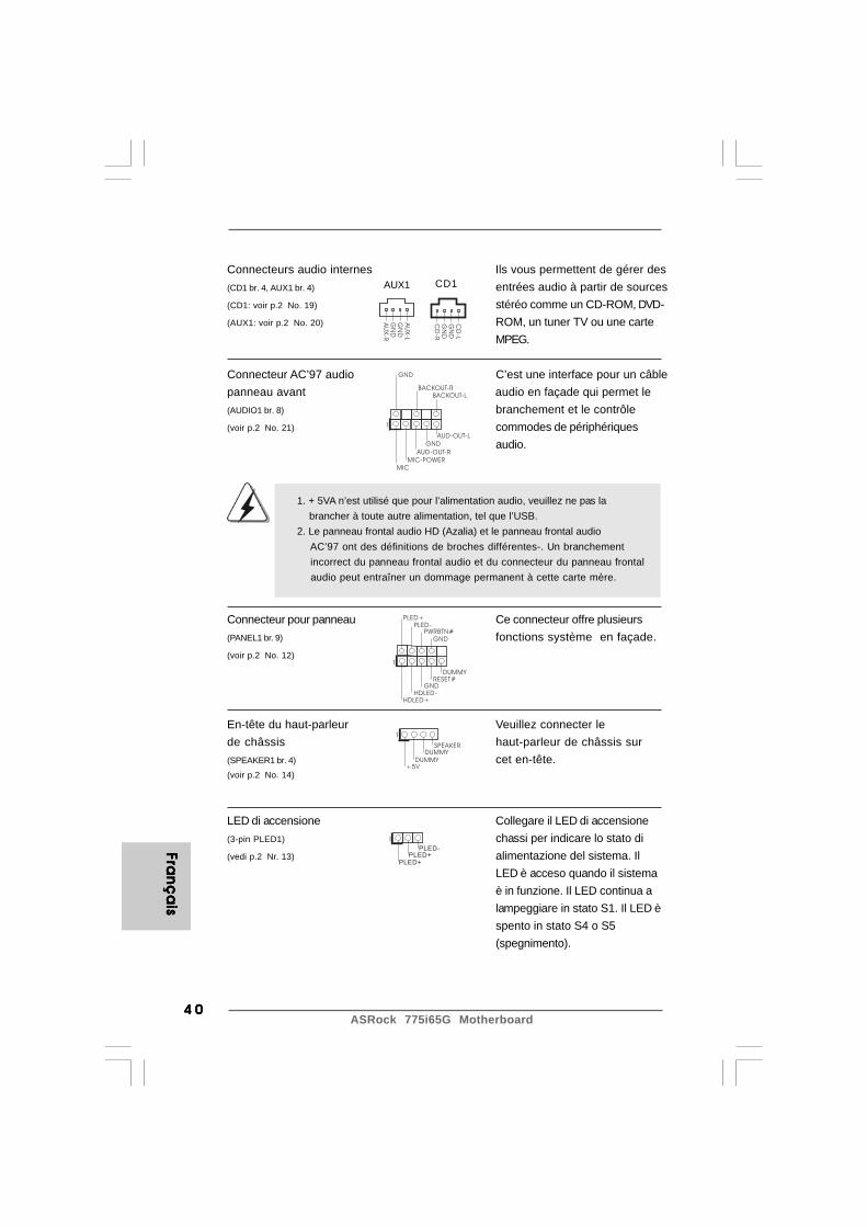
Connecteurs audio internes Ils vous permettent de gérer des(CD1 br. 4, AUX1 br. 4) entrées audio à partir de sources(CD1: voir p.2 No. 19) stéréo comme un CD-ROM, DVD-(AUX1: voir p.2 No. 20) ROM, un tuner TV ou une carte
MPEG.
Connecteur AC’97 audio C’est une interface pour un câblepanneau avant audio en façade qui permet le(AUDIO1 br. 8) branchement et le contrôle(voir p.2 No. 21) commodes de périphériques
audio.
Connecteur pour panneau Ce connecteur offre plusieurs(PANEL1 br. 9) fonctions système en façade.(voir p.2 No. 12)
En-tête du haut-parleur Veuillez connecter lede châssis haut-parleur de châssis sur(SPEAKER1 br. 4) cet en-tête.(voir p.2 No. 14)
LED di accensione Collegare il LED di accensione(3-pin PLED1) chassi per indicare lo stato di(vedi p.2 Nr. 13) alimentazione del sistema. Il
LED è acceso quando il sistemaè in funzione. Il LED continua alampeggiare in stato S1. Il LED èspento in stato S4 o S5(spegnimento).
1. + 5VA n’est utilisé que pour l’alimentation audio, veuillez ne pas la brancher à toute autre alimentation, tel que l’USB.2. Le panneau frontal audio HD (Azalia) et le panneau frontal audio AC’97 ont des définitions de broches différentes-. Un branchement incorrect du panneau frontal audio et du connecteur du panneau frontal audio peut entraîner un dommage permanent à cette carte mère.
GND
AUD-OUT-L
1
BACKOUT-R
GND
AUD-OUT-RMIC-POWER
MIC
BACKOUT-L
CD
-L
GN
D
GN
D
CD
-R
AU
X-L
GN
D
GN
D
AU
X-R
CD1AUX1

4 14 14 14 14 1ASRock 775i65G Motherboard
GND
+12VCHA_FAN_SPEED
GND
+12V
CPU_FAN_SPEED
FAN_SPEED_CONTROL
Fra
nFr
an
Fra
nFr
an
Fra
nç
ais
ça
isç
ais
ça
isç
ais
Connecteur du ventilateur Veuillez connecter le câble dude châssis ventilateur du châssis sur ce(CHA_FAN1 br. 3) connecteur en branchant le fil(voir p.2 No. 11) noir sur la broche de terre.
Connecteur du ventilateur Veuillez connecter le câble dede l’UC ventilateur d’UC sur ce(CPU_FAN1 br. 4) connecteur et brancher le fil(voir p.2 No. 4) noir sur la broche de terre.
En-tête d’alimentation ATX Veuillez connecter l’unité(ATXPWR1 br. 20) d’alimentation ATX sur cet en-(voir p.2 No. 27) tête.
Connecteur d’alimentation Veuillez noter qu’il est nécessaire12V ATX de connecter une unité(ATX12V2 br. 4) d’alimentation électrique avec(voir p.2 No. 1) prise ATX 12V sur ce connecteur
afin d’avoir une alimentationsuffisante. Faute de quoi, il nesera pas possible de mettre soustension.
ASRock 775i65G Motherboard4 24 24 24 24 2
Fran
ça
isFra
nç
ais
Fran
ça
isFra
nç
ais
Fran
ça
is
2. Informations sur le BIOS2. Informations sur le BIOS2. Informations sur le BIOS2. Informations sur le BIOS2. Informations sur le BIOSLa puce Flash Memory sur la carte mère stocke le Setup du BIOS. Lorsque vousdémarrez l’ordinateur, veuillez presser <F2> pendant le POST (Power-On-Self-Test) pour entrer dans le BIOS; sinon, le POST continue ses tests de routine. Sivous désirez entrer dans le BIOS après le POST, veuillez redémarrer le systèmeen pressant <Ctl> + <Alt> + <Suppr>, ou en pressant le bouton de reset sur leboîtier du système.Vous pouvez également redémarrer en éteignant le système et en le rallumant.L’utilitaire d’installation du BIOS est conçu pour être convivial. C’est un programmepiloté par menu, qui vous permet de faire défiler par ses divers sous-menus et dechoisir parmi les choix prédéterminés. Pour des informations détaillées sur leBIOS, veuillez consulter le Guide de l’utilisateur (fichier PDF) dans le CD technique.
3. Informations sur le CD de support3. Informations sur le CD de support3. Informations sur le CD de support3. Informations sur le CD de support3. Informations sur le CD de supportCette carte mère supporte divers systèmes d’exploitation Microsoft® Windows®:98SE / ME / 2000 / XP. Le CD technique livré avec cette carte mère contient lespilotes et les utilitaires nécessaires pour améliorer les fonctions de la carte mère.Pour utiliser le CD technique, insérez-le dans le lecteur de CD-ROM. Le Menuprincipal s’affiche automatiquement si “AUTORUN” est activé dans votreordinateur. Si le Menu principal n’apparaît pas automatiquement, localisez dans leCD technique le fichier “ASSETUP.EXE” dans le dossier BIN et double-cliquezdessus pour afficher les menus.

4 34 34 34 34 3ASRock 775i65G Motherboard
Ita
lian
oIt
alia
no
Ita
lian
oIt
alia
no
Ita
lian
o
1. Introduzione1. Introduzione1. Introduzione1. Introduzione1. IntroduzioneGrazie per aver scelto una scheda madre ASRock 775i65G, una scheda madreaffidabile prodotta secondo i severi criteri di qualità ASRock. Le prestazioni eccellentie il design robusto si conformano all’impegno di ASRock nella ricerca della qualità edella resistenza.Questa Guida Rapida all’Installazione contiene l’introduzione alla motherboard e laguida passo-passo all’installazione. Informazioni più dettagliate sulla motherboard sipossono trovare nel manuale per l’utente presente nel CD di supporto.
Le specifiche della scheda madre e il software del BIOSpossono essere aggiornati, pertanto il contenuto di questomanuale può subire variazioni senza preavviso. Nel caso in cuiquesto manuale sia modificato, la versione aggiornata saràdisponibile sul sito di ASRock senza altro avviso. Sul sito ASRocksi possono anche trovare le più recenti schede VGA e gli elenchidi CPU supportate.ASRock website http://www.asrock.comSe si necessita dell’assistenza tecnica per questa schedamadre, visitare il nostro sito per informazioni specifiche sulmodello che si sta usando.www.asrock.com/support/index.asp
1.1 Contenuto della confezione1.1 Contenuto della confezione1.1 Contenuto della confezione1.1 Contenuto della confezione1.1 Contenuto della confezioneScheda madre ASRock 775i65G
(Micro ATX Form Factor: 9.6-in x 8.0-in, 24.4 cm x 20.3 cm)Guida di installazione rapida ASRock 775i65GCD di supporto ASRock 775i65GUn cavo IDE 80-pin Ultra ATA 66/100Un cavo dati Serial ATA (SATA) (Opzionale)Un I/O Shield
ASRock 775i65G Motherboard4 44 44 44 44 4
Italia
no
Italia
no
Italia
no
Italia
no
Italia
no
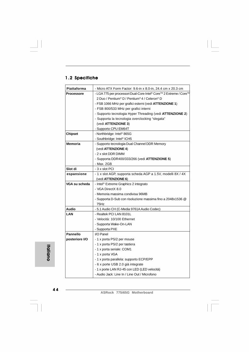
1 .21 .21 .21 .21 .2 SpecificheSpecificheSpecificheSpecificheSpecifiche
Piattaforma - Micro ATX Form Factor: 9.6-in x 8.0-in, 24.4 cm x 20.3 cm Processore - LGA 775 per processori Dual-Core Intel® CoreTM 2 Extreme / CoreTM
2 Duo / Pentium® D / Pentium® 4 / Celeron® D- FSB 1066 MHz per grafici esterni (vedi ATTENZIONE 1)- FSB 800/533 MHz per grafici interni- Supporto tecnologia Hyper Threading (vedi ATTENZIONE 2)- Supporta la tecnologia overclocking “slegata” (vedi ATTENZIONE 3)- Supporto CPU EM64T
Chipset - Northbridge: Intel® 865G- Southbridge: Intel® ICH5
Memoria - Supporto tecnologia Dual Channel DDR Memory (vedi ATTENZIONE 4)- 2 x slot DDR DIMM- Supporta DDR400/333/266 (vedi ATTENZIONE 5)- Max. 2GB
Slot di - 3 x slot PCI espansione - 1 x slot AGP, supporta scheda AGP a 1.5V, modelli 8X / 4X
(vedi ATTENZIONE 6) VGA su scheda - Intel® Extreme Graphics 2 integrato
- VGA DirectX 8.0- Memoria massima condivisa 96MB- Supporta D-Sub con risoluzione massima fino a 2048x1536 @ 75Hz
Audio - 5.1 Audio CH (C-Media 9761A Audio Codec) LAN - Realtek PCI LAN 8101L
- Velocità: 10/100 Ethernet- Supporta Wake-On-LAN- Supporta PXE
Pannello I/O Panel posteriore I/O - 1 x porta PS/2 per mouse
- 1 x porta PS/2 per tastiera- 1 x porta seriale: COM1- 1 x porta VGA- 1 x porta parallela: supporto ECP/EPP- 6 x porte USB 2.0 già integrate- 1 x porte LAN RJ-45 con LED (LED velocità)- Audio Jack: Line In / Line Out / Microfono

4 54 54 54 54 5ASRock 775i65G Motherboard
Ita
lian
oIt
alia
no
Ita
lian
oIt
alia
no
Ita
lian
o
Connettori - 2 x connettori SATA 1.5Go/s (Non supporta le funzioni “RAID” e “Collegamento a caldo”)- 2 x connettori ATA100 IDE (supporta fino a 4 dispositivi IDE)- 1 x porta Floppy- 1 x connettore modulo infrarossi- 1 x LED di accensione- Connettore ventolina CPU (4-pin)- Connettore ventolina telaio (3-pin)- 20-pin collettore alimentazione ATX- 4-pin connettore ATX 12V- Connettori audio interni- Connettore audio sul pannello frontale- 2 x Collettore USB 2.0 (supporto di 4 porte USB 2.0, 2 delle quali condivise con USB45) (vedi ATTENZIONE 7)
BIOS - 4Mb AMI legal BIOS- Supporta “Plug and Play”- Compatibile con ACPI 1.1 wake up events- Supporta jumperfree- Supporta SMBIOS 2.3.1
CD di - Driver, utilità, software antivirus (Versione dimostrativa), CyberLink supporto MediaEspresso 6.5 Trial, Suite multimediale ASRock MAGIX - OEM Caratteristi- - Caricatore ASRock APP Charger (vedi ATTENZIONE 8) ca speciale - Booster ibrido:
- Stepless control per frequenza del processore (vedi ATTENZIONE 9)- ASRock U-COP (vedi ATTENZIONE 10)- Boot Failure Guard (B.F.G.)
Monitor- - Sensore per la temperatura del processore aggio - Sensore temperatura scheda madre Hardware - Indicatore di velocità per la ventola del processore
- Indicatore di velocità per la ventola di raffreddamento- Ventola CPU silenziosa- Voltaggio: +12V, +5V, +3.3V, Vcore
Compatibi- - Microsoft® Windows® 98SE / ME / 2000 / XP lità SO Certificazioni - FCC, CE, WHQL * Per ulteriori informazioni, prego visitare il nostro sito internet: http://www.asrock.com
ASRock 775i65G Motherboard4 64 64 64 64 6
Italia
no
Italia
no
Italia
no
Italia
no
Italia
no
ATTENZIONE!1. FSB1066-CPU è supportato solo se si inserisce ñla scheda AGP VGA
nello slot AGP. Inoltre, se si utilizza un FSB1066-CPU su questa schedamadre, adoperare un modulo di memoria DDR400 CL2.5.
2. Per il settaggio della “Tecnologia Hyper-Threading”, per favorecontrollare pagina 29 del Manuale dell’utente all’interno del CD disupporto.
3. Questa scheda madre supporta la tecnologia overclocking “slegata”.Per i dettagli leggere “Tecnologia di Untied Overclocking” a pagina 19.
4. Questa scheda madre supporta la tecnologia Dual Channel Memory.Prima di implementare la tecnologia Dual Channel Memory, assicurarsidi leggere la guida all’installazione dei moduli di memoria, a pagina13, per seguire un’installazione appropriata.
5. Controllare la tavola che segue per le frequenze di supporto di memoriae le loro corrispondenti frequenze CPU FSB.
Frequenza CPU FSB Frequenza supporto di memoria800 DDR266, DDR320*, DDR400533 DDR266, DDR333
* Quando si utilizza una CPU FSB800 su questa scheda madre,funzionerà a DDR320 se si adotta un modulo di memoria DDR333.
6. NON usare schede AGP da 3,3 V nello slot AGP di questamotherboard! Ciò potrebbe provocare danni permanenti!
7. La Gestione Risorse per USB 2.0 funziona perfettamente conMicrosoft® Windows® XP SP1; SP2/2000 SP4. Potrebbe dare qualcheproblema con Microsoft® Windows® 98/ME.
8. Se vuoi un modo rapido e indipendente per caricare i dispositivi Apple,come iPhone/iPod/iPad Touch, ASRock ha preparato una soluzionemeravigliosa: ASRock APP Charger. Basta installare il driver APPCharger per caricare l’iPhone più rapidamente rispetto al computer,con una velocità maggiore del 40%. ASRock APP Charger permette dicaricare simultaneamente molti dispositivi Apple in modo rapido esupporta anche il caricamento continuato quando il PC accede allamodalità di Standby (S1), Ibernazione (S4) o Spegnimento (S5). Unavolta installato il driver APP Charger si otterranno prodigi e comoditàmai avuti prima.Sito ASRock: http://www.asrock.com/Feature/AppCharger/index.asp
AVVISOSi prega di prendere atto che la procedura di overclocking implica dei rischi, come anchela regolazione delle impostazioni del BIOS, l’applicazione della tecnologia Untied OverclockingTechnology, oppure l’uso di strumenti di overclocking forniti da terzi. L’overclocking puòinfluenzare la stabilità del sistema, ed anche provocare danni ai componenti ed alleperiferiche del sistema. La procedura è eseguita a proprio rischio ed a proprie spese. Noinon possiamo essere ritenuti responsabili per possibili danni provocati dall’overclocking.
4 74 74 74 74 7ASRock 775i65G Motherboard
Ita
lian
oIt
alia
no
Ita
lian
oIt
alia
no
Ita
lian
o
9. Anche se questa motherboard offre il controllo stepless, non siconsiglia di effettuare l’overclocking. L’uso di frequenze diverse daquelle raccomandate per il bus CPU possono provocare l’instabilitàdel sistema o danneggiare la CPU.
10. Se il processore si surriscalda, il sistema si chiude automaticamente.Prima di riavviare il sistema, assicurarsi che la ventolina CPU dellascheda madre funzioni correttamente; scollegare e ricollegare il cavod’alimentazione. Per migliorare la dissipazione del calore, ricordare diapplicare l’apposita pasta siliconica tra il processore e il dissipatorequando si installa il sistema.

ASRock 775i65G Motherboard4 84 84 84 84 8
Italia
no
Italia
no
Italia
no
Italia
no
Italia
no
1.3 Setup dei Jumpers1.3 Setup dei Jumpers1.3 Setup dei Jumpers1.3 Setup dei Jumpers1.3 Setup dei JumpersL’illustrazione mostra come sono settati i jumper.Quando il ponticello è posizionato sui pin, il jumperè “CORTOCIRCUITATO”. Se sui pin non ci sonoponticelli, il jumper è “APERTO”. L’illustrazionemostra un jumper a 3 pin in cui il pin1 e il pin2sono “CORTOCIRCUITATI” quando il ponticello èposizionato su questi pin.
Jumper Settaggio del Jumper DescrizioneJR1 (vedi p.2 Nr. 22)
JL1 (vedi p.2 Nr. 22)
Nota: Se i jumper JL1 e JR1 sono chiusi, funzionano sia i connettori audio frontaliche posteriori.
Resettare la CMOS(CLRCMOS0, jumper a 3 pin)(vedi p.2 Nr. 15)
Nota: CLRCMOS0 permette di cancellare i dati presenti nel CMOS. I dati del CMOScomprendono le informazioni di configurazione quali la password di sistema,data, ora, e i parametri di configurazione del sistema. Per cancellare eripristinare i parametri del sistema, spegnere il computer e togliere il cavo dialimentazione dalla presa di corrente. Dopo aver lasciato trascorrere 15secondi, utilizzare un cappuccio jumper per cortocircuitare i pin 2 e 3 suCLRCMOS0 per 5 secondi. Dopo aver cortocircuitato il jumper Clear CMOSjumper, togliere il terminatore jumper. Non cancellare la CMOS subito dopo averaggiornato il BIOS. Se è necessario cancellare la CMOS una volta completatol’aggiornamento del BIOS, è necessario riavviare prima il sistema, e poispegnerlo prima di procedere alla cancellazione della CMOS.
CORTOCIRCUITATO APERTO
JR1 JL1
2_31_2
AzzeramentoCMOS
Impostazionepredefinita

4 94 94 94 94 9ASRock 775i65G Motherboard
FLOPPY1Pin1
IDE1PIN1IDE2PIN1
SATA2
SATA1
1.4 Collettori e Connettori su Scheda1.4 Collettori e Connettori su Scheda1.4 Collettori e Connettori su Scheda1.4 Collettori e Connettori su Scheda1.4 Collettori e Connettori su Scheda
I collettori ed i connettori su scheda NON sono dei jumper. NON installarecappucci per jumper su questi collettori e connettori. L’installazione dicappucci per jumper su questi collettori e connettori provocherà dannipermanenti alla scheda madre!
Connettore delFloppy disk(33-pin FLOPPY1)(vedi p.2 Nr. 18)
Nota: Assicurarsi che il lato del cavo con la striscia rossa sia inserito nel lato Pin1del connettore.
Connettore IDE primario (blu) Connettore IDE secondario (nero)(39-pin IDE1, vedi p.2 Nr. 7) (39-pin IDE2, vedi p.2 Nr. 6)
Connettore blu Connettore neroalla schedamadre all’hard disk drive
Cavo ATA 66/100 a 80 pin
Nota: Se utilizzate un solo dispositivo IDE su questa scheda madre, imposta taledispositivo come “Master”. Fate riferimento alle istruzioni del produttore deldispositivo IDE per maggiori dettagli. Inoltre, per ottimizzare compatibilità eprestazioni, connettete l’hard disk al connettore primario IDE (IDE1, blu) e ilCD-ROM al connettore IDE secondario (IDE2, nero).
Connettori Serial ATA Questi due connettori Serial ATA(SATA1: vedi p.2 Nr. 10) (SATA) supportano cavi dati(SATA2: vedi p.2 Nr. 9) SATA per dispositivi di
immagazzinamento interni.ATA (SATA) supportano caviSATA per dispositivi di memoriainterni. L’interfaccia SATAattuale permette velocità ditrasferimento dati fino a 1.5 Gb/s.
Lato del Pin1 con la striscia rossa
Ita
lian
oIt
alia
no
Ita
lian
oIt
alia
no
Ita
lian
o
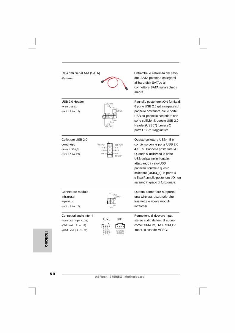
ASRock 775i65G Motherboard5 05 05 05 05 0
USB_PWR
USB_PWR
P+7P-7
P+6P-6
GND
GND
DUMMY
1
USB_PWR
1
P-5
GND
DUMMY
USB_PWR
P+5
GND
P-4
P+4
1
IRTX
IRRXGND
+5VSBDUMMY
Italia
no
Italia
no
Italia
no
Italia
no
Italia
no
Cavi dati Serial ATA (SATA) Entrambe le estremità del cavo(Opzionale) dati SATA possono collegarsi
all’hard disk SATA o alconnettore SATA sulla schedamadre.
USB 2.0 Header Pannello posteriore I/O è fornita di(9-pin USB67) 6 porte USB 2.0 già integrate sul(vedi p.2 Nr. 16) pannello posteriore. Se le porte
USB sul pannello posteriore nonsono sufficienti, questo USB 2.0Header (USB67) fornisce 2porte USB 2.0 aggiuntive.
Collettore USB 2.0 Questo collettore USB4_5 ècondiviso condiviso con le porte USB 2.0(9-pin USB4_5) 4 e 5 su Pannello posteriore I/O.(vedi p.2 Nr. 26) Quando si utilizzano le porte
USB del pannello frontale,attaccando il cavo USBpannello frontale a questocollettore (USB4_5), le porte 4e 5 su Pannello posteriore I/O nonsaranno in grado di funzionare.
Connettore modulo Questo connettore supportainfrarossi una wireless opzionale che(5-pin IR1) trasmette e riceve moduli(vedi p.2 Nr. 17) infrarossi.
Connettori audio interni Permettono di ricevere input(4-pin CD1, 4-pin AUX1) stereo audio da fonti di suono(CD1: vedi p.2 Nr. 19) come CD-ROM, DVD-ROM,TV(AUx1: vedi p.2 Nr. 20) tuner, o schede MPEG.C
D-L
GN
DG
ND
CD
-R
AU
X-L
GN
DG
ND
AU
X-R
CD1AUX1
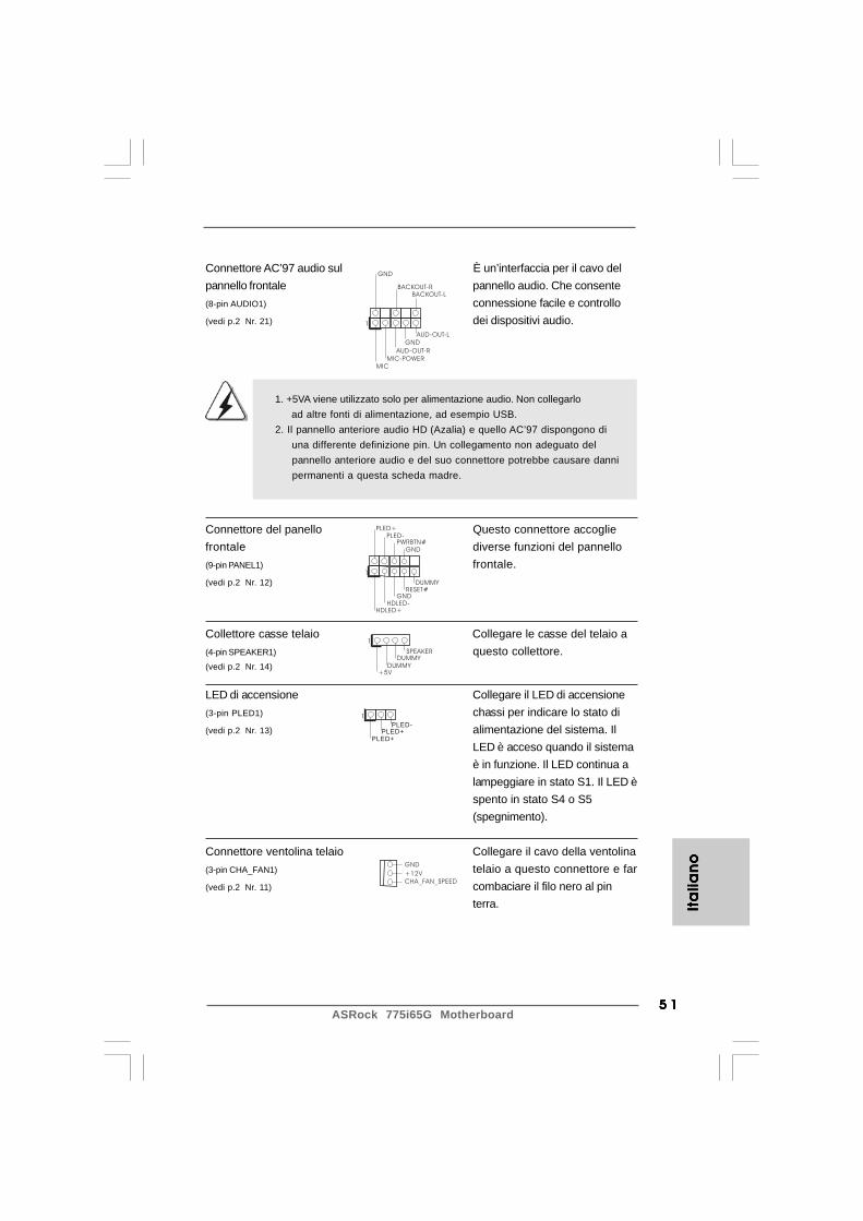
5 15 15 15 15 1ASRock 775i65G Motherboard
GND
+12VCHA_FAN_SPEED
+5V
DUMMYDUMMY
SPEAKER
1
GND
PWRBTN#PLED-
PLED+
DUMMYRESET#
GND
HDLED+HDLED-
1
1
PLED+
PLED+
PLED-
Connettore AC’97 audio sul È un’interfaccia per il cavo delpannello frontale pannello audio. Che consente(8-pin AUDIO1) connessione facile e controllo(vedi p.2 Nr. 21) dei dispositivi audio.
Connettore del panello Questo connettore accogliefrontale diverse funzioni del pannello(9-pin PANEL1) frontale.(vedi p.2 Nr. 12)
Collettore casse telaio Collegare le casse del telaio a(4-pin SPEAKER1) questo collettore.(vedi p.2 Nr. 14)
LED di accensione Collegare il LED di accensione(3-pin PLED1) chassi per indicare lo stato di(vedi p.2 Nr. 13) alimentazione del sistema. Il
LED è acceso quando il sistemaè in funzione. Il LED continua alampeggiare in stato S1. Il LED èspento in stato S4 o S5(spegnimento).
Connettore ventolina telaio Collegare il cavo della ventolina(3-pin CHA_FAN1) telaio a questo connettore e far(vedi p.2 Nr. 11) combaciare il filo nero al pin
terra.
1. +5VA viene utilizzato solo per alimentazione audio. Non collegarlo ad altre fonti di alimentazione, ad esempio USB.2. Il pannello anteriore audio HD (Azalia) e quello AC’97 dispongono di una differente definizione pin. Un collegamento non adeguato del pannello anteriore audio e del suo connettore potrebbe causare danni permanenti a questa scheda madre.
Ita
lian
oIt
alia
no
Ita
lian
oIt
alia
no
Ita
lian
o
GND
AUD-OUT-L
1
BACKOUT-R
GND
AUD-OUT-RMIC-POWER
MIC
BACKOUT-L
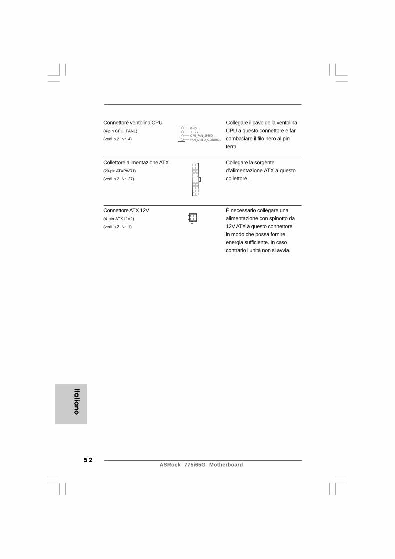
ASRock 775i65G Motherboard5 25 25 25 25 2
GND
+12V
CPU_FAN_SPEED
FAN_SPEED_CONTROL
Italia
no
Italia
no
Italia
no
Italia
no
Italia
no
Connettore ventolina CPU Collegare il cavo della ventolina(4-pin CPU_FAN1) CPU a questo connettore e far(vedi p.2 Nr. 4) combaciare il filo nero al pin
terra.
Collettore alimentazione ATX Collegare la sorgente(20-pin ATXPWR1) d’alimentazione ATX a questo(vedi p.2 Nr. 27) collettore.
Connettore ATX 12V È necessario collegare una(4-pin ATX12V2) alimentazione con spinotto da(vedi p.2 Nr. 1) 12V ATX a questo connettore
in modo che possa fornireenergia sufficiente. In casocontrario l’unità non si avvia.
5 35 35 35 35 3ASRock 775i65G Motherboard
Ita
lian
oIt
alia
no
Ita
lian
oIt
alia
no
Ita
lian
o
2. Informazioni sul BIOS2. Informazioni sul BIOS2. Informazioni sul BIOS2. Informazioni sul BIOS2. Informazioni sul BIOSLa Flash Memory sulla scheda madre contiene le Setup Utility. Quando si avvia ilcomputer, premi <F2> durante il Power-On-Self-Test (POST) della Setup utility delBIOS; altrimenti, POST continua con i suoi test di routine. Per entrare il BIOS Setupdopo il POST, riavvia il sistema premendo <Ctl> + <Alt> + <Delete>, o premi il tastodi reset sullo chassis del sistema. Per informazioni più dettagliate circa il Setup delBIOS, fare riferimento al Manuale dell’Utente (PDF file) contenuto nel cd disupporto.
3. Software di supporto e informazioni3. Software di supporto e informazioni3. Software di supporto e informazioni3. Software di supporto e informazioni3. Software di supporto e informazioni su CD su CD su CD su CD su CDQuesta scheda madre supporta vari sistemi operativi Microsoft® Windows®: 98SE / ME/ 2000 / XP. Il CD di supporto a corredo della scheda madre contiene i driver e utilitànecessari a potenziare le caratteristiche della scheda.Inserire il CD di supporto nel lettore CD-ROM. Se la funzione “AUTORUN” è attivata nelcomputer, apparirà automaticamente il Menù principale. Se il Menù principale nonappare automaticamente, posizionarsi sul file “ASSETUP.EXE” nel CESTINO del CD disupporto e cliccare due volte per visualizzare i menù.

ASRock 775i65G Motherboard5 45 45 45 45 4
Espa
ño
lEsp
añ
ol
Espa
ño
lEsp
añ
ol
Espa
ño
l
1. Introducción1. Introducción1. Introducción1. Introducción1. IntroducciónGracias por su compra de ASRock 775i65G placa madre, una placa de confianzaproducida bajo el control de calidad estricto y persistente. La placa madre proveerealización excelente con un diseño robusto conforme al compromiso de calidad yresistencia de ASRock.Esta Guía rápida de instalación contiene una introducción a la placa base y una guíade instalación paso a paso. Puede encontrar una información más detallada sobre laplaca base en el manual de usuario incluido en el CD de soporte.
Porque las especificaciones de la placa madre y el software de BIOSpodrían ser actualizados, el contenido de este manual puede sercambiado sin aviso. En caso de cualquier modificación de este manual,la versión actualizada estará disponible en el website de ASRock sinprevio aviso. También encontrará las listas de las últimas tarjetas VGA yCPU soportadas en la página web de ASRock.Website de ASRock http://www.asrock.comSi necesita asistencia técnica en relación con esta placa base, visitenuestra página web con el número de modelo específico de su placa.www.asrock.com/support/index.asp
1.1 Contenido de la caja1.1 Contenido de la caja1.1 Contenido de la caja1.1 Contenido de la caja1.1 Contenido de la cajaPlaca base ASRock 775i65G
(Factor forma Micro ATX: 24,4 cm x 20.3 cm, 9,6” x 8,0”)Guía de instalación rápida de ASRock 775i65GCD de soporte de ASRock 775i65GUna cinta de datos IDE de conducción 80 Ultra ATA 66/100Un Cable de Datos Serial ATA (SATA) (Opcional)Una protección I/O

5 55 55 55 55 5ASRock 775i65G Motherboard
Esp
añ
ol
Esp
añ
ol
Esp
añ
ol
Esp
añ
ol
Esp
añ
ol
1 .21 .21 .21 .21 .2 EspecificaciónEspecificaciónEspecificaciónEspecificaciónEspecificación
Plataforma - Factor forma Micro ATX: 24,4 cm x 20.3 cm, 9,6” x 8,0” Procesador - LGA 775 para Intel® Dual-Core CoreTM 2 Extreme / CoreTM 2 Duo
/ Pentium® D / Pentium® 4 / Celeron® D- FSB 1066 MHz para gráficos externos (ver ATENCIÓN 1)- FSB 800/533 MHz para gráficos internos- Admite tecnología Hyper Threading (ver ATENCIÓN 2)- Admite tecnología de aumento de velocidad liberada
(vea ATENCIÓN 3)- Admite CPU EM64T
Chipset - North Bridge: Intel® 865G- South Bridge: Intel® ICH5
Memoria - Soporte de Tecnología de Memoria de Doble Canal (ver ATENCIÓN 4)- 2 x DDR DIMM slots- Soporta DDR400/333/266 (vea ATENCIÓN 5)- Max. 2GB
Ranuras de - 3 x ranuras PCI Expansión - 1 x slot AGP, soporta tarjeta AGP de 1.5V, 8X / 4X
(ver ATENCIÓN 6) VGA OnBoard - Intel® Extreme Graphics 2 Integrado
- VGA DirectX 8.0- 96MB de Memoria máxima compartida- Admite D-Sub con una resolución máxima de 2048x1536 a 75 Hz
Audio - Sonido de 5.1 Canales (Códec de sonido C-Media 9761A) LAN - Realtek PCI LAN 8101L
- Velocidad: 10/100 Ethernet- Soporta Wake-On-LAN- Compatible con PXE
Entrada/Salida I/O Panel de Panel - 1 x puerto de ratón PS/2 Trasero - 1 x puerto de teclado PS/2
- 1 x puerto serial: COM1- 1 x puerto VGA- 1 x puerto paralelo: soporta ECP/EPP- 6 x puertos USB 2.0 predeterminados- 1 x Puerto LAN RJ-45 con LED (LED de VELOCIDAD)- Audio Jack: Line In / Line Out / Micrófono

ASRock 775i65G Motherboard5 65 65 65 65 6
Espa
ño
lEsp
añ
ol
Espa
ño
lEsp
añ
ol
Espa
ño
l
Conectores - 2 x conexiones SATA, admiten una velocidad de transferencia de datos de hasta 1,5Gb/s (No soporta las funciones “RAID” y “Conexión en caliente”)- 2 x ATA100 conexiones IDE (admite hasta 4 dispositivos IDE)- 1 x puerto Floppy- 1 x cabezal de Módulo Infrarrojos- 1 x cabecera de indicador LED de encendido- Conector del ventilador del CPU (4-pin)- Conector del ventilador del chasis (3-pin)- 20-pin cabezal de alimentación ATX- 4-pin conector de ATX 12V power- Conector de Audio Interno- Conector de audio de panel frontal- 2 x Cabezal USB 2.0 (soporta 4 puertos USB 2.0; 2 de ellos son compartidos con USB 45) (vea ATENCIÓN 7)
BIOS - 4Mb AMI legal BIOS- Soporta “Plug and Play”- ACPI 1.1 compliance wake up events- Soporta “jumper free setup”- Soporta SMBIOS 2.3.1
CD de soport - Controladores, Utilerías, Software de Anti Virus (Versión de prueba), Prueba de CyberLink MediaEspresso 6.5, Conjunto multimedia ASRock MAGIX - OEM
Característica - ASRock APP Charger (vea ATENCIÓN 8) Única - Amplificador Híbrido:
- Stepless control de frecuencia de CPU (vea ATENCIÓN 9)- ASRock U-COP (vea ATENCIÓN 10)- Protección de Falla de Inicio (B.F.G.)
Monitor Hardware - Sensibilidad a la temperatura del procesador- Sensibilidad a la temperatura de la placa madre- Taquímetros de los ventiladores del procesador y del procesador- Taquímetros de los ventiladores del procesador y del chasis- Ventilador silencioso para procesador- Monitor de Voltaje: +12V, +5V, +3.3V, Vcore
OS - En conformidad con Microsoft® Windows® 98SE / ME / 2000 / XP
Certificaciones - FCC, CE, WHQL
5 75 75 75 75 7ASRock 775i65G Motherboard
Esp
añ
ol
Esp
añ
ol
Esp
añ
ol
Esp
añ
ol
Esp
añ
ol
AAAAATENCIÓN!TENCIÓN!TENCIÓN!TENCIÓN!TENCIÓN!1. Es posible dar soporte a FSB1066-CPU sólo si instala una tarjeta AGP
VGA en su ranura AGP. Además, si utiliza un FSB1066-CPU en estaplaca base, deberá utilizar un módulo de memoria DDR400 CL2.5.
2. Por favor consulte página 29 del Manual del Usuario en el soporteCD sobre la configuración de Hyper-Threading Technology.
3. Esta placa base admite la tecnología de aumento de velocidad liberada.Por favor lea “Tecnología de Forzado de Reloj (Overclocking) norelacionado” en la página 19 para obtener detalles.
4. Esta placa base soporta Tecnología de Memoria de Doble Canal. Antes deimplementar la Tecnología de Memoria de Doble Canal, asegúrese de leerla guía de instalación de módulos de memoria en la página 13 para sucorrecta instalación.
5. Compruebe la tabla siguiente para conocer la frecuencia de soporte dememoria y su frecuencia FSB CPU correspondiente.
Frecuencia FSB CPU Frecuencia de soporte de memoria800 DDR266, DDR320*, DDR400533 DDR266, DDR333
* Al usar un FSB800-CPU en esta placa base, se ejecutará a DDR320 siadquiere un módulo de memoria DDR333.
6. NO utilice una tarjeta AGP de 3,3V AGP en la ranura AGP de estaplaca base. Podría causar daños permanentes.
7. Power Management para USB 2.0 funciona bien bajo Microsoft®
Windows® XP SP1; SP2/2000 SP4. Es posible que no funcionepropiamente bajo Microsoft® Windows® 98/ME.
ADVERTENCIATenga en cuenta que hay un cierto riesgo implícito en las operaciones de aumento de lavelocidad del reloj, incluido el ajuste del BIOS, aplicando la tecnología de aumento develocidad liberada o utilizando las herramientas de aumento de velocidad de otrosfabricantes. El aumento de la velocidad puede afectar a la estabilidad del sistema e,incluso, dañar los componentes y dispositivos del sistema. Esta operación se deberealizar bajo su propia responsabilidad y Ud. debe asumir los costos. No asumimosninguna responsabilidad por los posibles daños causados por el aumento de la velocidaddel reloj.
* Para más información sobre los productos, por favor visite nuestro sitio web: http://www.asrock.com

ASRock 775i65G Motherboard5 85 85 85 85 8
Espa
ño
lEsp
añ
ol
Espa
ño
lEsp
añ
ol
Espa
ño
l
8. Si desea una forma más rápida y menos limitada de cargar susdispositivos de Apple; como por ejemplo iPhone, iPod o iPad Touch,ASRock ha creado una fantástica solución para usted: ASRock APPCharger. Simplemente mediante la instalación del controlador de APPCharger, podrá cargar su iPhone de forma mucho más rápida queantes, hasta un 40%, desde su equipo. ASRock APP Charger le permitecargar de forma rápida muchos dispositivos de Apple simultáneamentee incluso podrá continuar la carga cuando su PC entre en modo deespera (S1), modo de hibernación (S4) o se apague (S5). Una vezinstalado el controlador de APP Charger, podrá disfrutar fácilmente deuna fantástica carga sin precedentes.Sitio web de ASRock: http://www.asrock.com/Feature/AppCharger/index.asp
9. Aunque esta placa base ofrece un control complete, no esrecomendable forzar la velocidad. Las frecuencias de bus de la CPUdistintas a las recomendadas pueden causar inestabilidad en elsistema o dañar la CPU.
10. Cuando la temperatura de CPU está sobre-elevada, el sistema va aapagarse automaticamente. Antes de reanudar el sistema, compruebesi el ventilador de la CPU de la placa base funciona apropiadamente ydesconecte el cable de alimentación, a continuación, vuelva a conectarlo.Para mejorar la disipación de calor, acuérdese de aplicar thermal greaseentre el procesador y el disipador de calor cuando usted instala elsistema de PC.
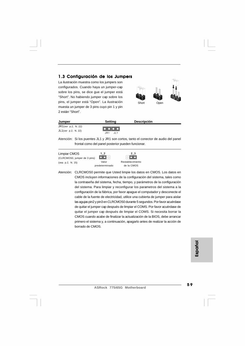
5 95 95 95 95 9ASRock 775i65G Motherboard
1.3 Configuración de los Jumpers1.3 Configuración de los Jumpers1.3 Configuración de los Jumpers1.3 Configuración de los Jumpers1.3 Configuración de los JumpersLa ilustración muestra como los jumpers sonconfigurados. Cuando haya un jumper-capsobre los pins, se dice gue el jumper está“Short”. No habiendo jumper cap sobre lospins, el jumper está “Open”. La ilustraciónmuesta un jumper de 3 pins cuyo pin 1 y pin2 están “Short”.
Jumper Setting DescripciónJR1(ver p.2, N. 22)
JL1(ver p.2, N. 22)
Atención: Si los puentes JL1 y JR1 son cortos, tanto el conector de audio del panelfrontal como del panel posterior pueden funcionar.
Limpiar CMOS(CLRCMOS0, jumper de 3 pins)
(vea p.2, N. 15)
Atención: CLRCMOS0 permite que Usted limpie los datos en CMOS. Los datos enCMOS incluyen informaciones de la configuración del sistema, tales comola contraseña del sistema, fecha, tiempo, y parámetros de la configuracióndel sistema. Para limpiar y reconfigurar los parametros del sistema a laconfiguración de la fábrica, por favor apague el computador y desconecte elcable de la fuente de electricidad, utilice una cubierta de jumper para aislarlas agujas pin2 y pin3 en CLRCMOS0 durante 5 segundos. Por favor acuérdasede quitar el jumper cap después de limpiar el COMS. Por favor acuérdase dequitar el jumper cap después de limpiar el COMS. Si necesita borrar laCMOS cuando acabe de finalizar la actualización de la BIOS, debe arrancarprimero el sistema y, a continuación, apagarlo antes de realizar la acción deborrado de CMOS.
Short Open
Esp
añ
ol
Esp
añ
ol
Esp
añ
ol
Esp
añ
ol
Esp
añ
ol
JR1 JL1
2_31_2
Valorpredeterminado
Restablecimientode la CMOS

ASRock 775i65G Motherboard6 06 06 06 06 0
FLOPPY1Pin1
IDE1PIN1 IDE2PIN1
SATA2
SATA1
Espa
ño
lEsp
añ
ol
Espa
ño
lEsp
añ
ol
Espa
ño
l
la banda roja debe quedar en
el mismo lado que el contacto 1
1.4 Cabezales y Conectores en Placas1.4 Cabezales y Conectores en Placas1.4 Cabezales y Conectores en Placas1.4 Cabezales y Conectores en Placas1.4 Cabezales y Conectores en Placas
Los conectores y cabezales en placa NO son puentes. NO coloque lascubiertas de los puentes sobre estos cabezales y conectores. El colocarcubiertas de puentes sobre los conectores y cabezales provocará undaño permanente en la placa base.
Conector de disquetera(33-pin FLOPPY1)
(ver p.2 N. 18)
Atención: Asegúrese que la banda roja del cable queda situado en el mismo lado queel contacto 1 de la conexión.
IDE conector primario (azul) IDE conector secundario (negra)(39-pin IDE1, ver p.2 N. 7) (39-pin IDE2, ver p.2 N. 6)
Conector azul Conector negro a placa madre a aparato IDE
Cable ATA 66/100 de conducción 80
Atención: Si utiliza solamente un dispositivo IDE en esta placa base, configúrelocomo “maestro”. Consulte las instrucciones del distribuidor del dispositivoIDE para conocer los detalles. Además, para optimizar la compatibilidad yel rendimiento, conecte el disco duro a la conexión IDE primaria,(IDE1, azul) y el CD-ROM a la conexión IDE secundaria (IDE2, negra).
Conexiones de serie ATA Estas dos conexiones de serie(SATA1: ver p.2, No. 10) ATA (SATA) admiten cables(SATA2: ver p.2, No. 9) SATA para dispositivos de
almacenamiento internos. Lainterfaz SATA actual permiteuna velocidad de transferenciade 1.5 Gb/s.
Cable de datos de Ambos extremos del cableserie ATA (SATA) pueden conectarse al disco(Opcional) duro SATA o la conexión de la
placa base.
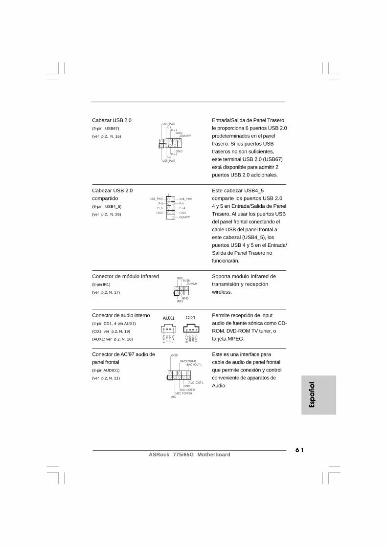
6 16 16 16 16 1ASRock 775i65G Motherboard
USB_PWR
USB_PWR
P+7P-7
P+6P-6
GND
GND
DUMMY
1
USB_PWR
1
P-5
GND
DUMMY
USB_PWR
P+5
GND
P-4
P+4
1
IRTX
IRRXGND
+5VSBDUMMY
GND
AUD-OUT-L
1
BACKOUT-R
GND
AUD-OUT-RMIC-POWER
MIC
BACKOUT-L
CD
-L
GN
DG
ND
CD
-R
AU
X-L
GN
DG
ND
AU
X-R
CD1AUX1
Cabezar USB 2.0 Entrada/Salida de Panel Trasero(9-pin USB67) le proporciona 6 puertos USB 2.0(ver p.2, N. 16) predeterminados en el panel
trasero. Si los puertos USBtraseros no son suficientes,este terminal USB 2.0 (USB67)está disponible para admitir 2puertos USB 2.0 adicionales.
Cabezar USB 2.0 Este cabezar USB4_5compartido comparte los puertos USB 2.0(9-pin USB4_5) 4 y 5 en Entrada/Salida de Panel(ver p.2, N. 26) Trasero. Al usar los puertos USB
del panel frontal conectando elcable USB del panel frontal aeste cabezal (USB4_5), lospuertos USB 4 y 5 en el Entrada/Salida de Panel Trasero nofuncionarán.
Conector de módulo Infrared Soporta módulo Infrared de(5-pin IR1) transmisión y recepción(ver p.2, N. 17) wireless.
Conector de audio interno Permite recepción de input(4-pin CD1, 4-pin AUX1) audio de fuente sónica como CD-(CD1: ver p.2, N. 19) ROM, DVD-ROM TV tuner, o(AUX1: ver p.2, N. 20) tarjeta MPEG.
Conector de AC’97 audio de Este es una interface parapanel frontal cable de audio de panel frontal(8-pin AUDIO1) que permite conexión y control(ver p.2, N. 21) conveniente de apparatos de
Audio.
Esp
añ
ol
Esp
añ
ol
Esp
añ
ol
Esp
añ
ol
Esp
añ
ol

ASRock 775i65G Motherboard6 26 26 26 26 2
GND
+12VCHA_FAN_SPEED
+5V
DUMMYDUMMY
SPEAKER
1
GND
PWRBTN#PLED-
PLED+
DUMMYRESET#
GND
HDLED+HDLED-
1
GND
+12V
CPU_FAN_SPEED
FAN_SPEED_CONTROL
1
PLED+
PLED+
PLED-
Espa
ño
lEsp
añ
ol
Espa
ño
lEsp
añ
ol
Espa
ño
l
Conector del panel del systema Este conector acomoda varias(9-pin PANEL1) funciones de panel frontal del(ver p.2, N. 12) systema.
Cabezal del altavoz del chasis Conecte el altavoz del chasis a(4-pin SPEAKER1) su cabezal.(ver p.2, N. 14)
Cabecera de indicador LED de encendido Conecte el indicador LED de(3-pin PLED1) encendido del chasis a esta(vea p.2, N. 13) cabecera para conocer el estado
de encendido del sistema. Elindicador LED se encenderá siel sistema se encuentra enfuncionamiento. El indicador LEDparpadeará en el estado S1. Elindicador LED se apagará en losestados S4 o S5 (apagado).
Conector del ventilador Conecte el cable del ventiladordel chasis del chasis a este conector y(3-pin CHA_FAN1) haga coincidir el cable negro(ver p.2, N. 11) con el conector de tierra.
Conector del ventilador Conecte el cable del ventiladorde la CPU de la CPU a este conector y(4-pin CPU_FAN1) haga coincidir el cable negro(ver p.2, N. 4) con el conector de tierra.
1. Se utilizan +5VA como potencia de sonido. No lo conecte a ninguna otra fuente de alimentación, como el USB.2. El panel frontal de sonido HD (Azalia) y el panel frontal de sonido AC’97 tienen diferentes definiciones de conexión. La conexión incorrecta del panel frontal y la cabecera frontal de sonido puede dañar esta placa base.

6 36 36 36 36 3ASRock 775i65G Motherboard
Esp
añ
ol
Esp
añ
ol
Esp
añ
ol
Esp
añ
ol
Esp
añ
ol
Cabezal de alimentación ATX Conecte la fuente de(20-pin ATXPWR1) alimentación ATX a su cabezal.(ver p.2, N. 27)
Conector de ATX 12V power Tenga en cuenta que es(4-pin ATX12V2) necesario conectar este(ver p.2, N. 1) conector a una toma de corriente
con el enchufe ATX 12V, demodo que proporcione suficienteelectricidad. De lo contrario nose podrá encender.

ASRock 775i65G Motherboard6 46 46 46 46 4
Espa
ño
lEsp
añ
ol
Espa
ño
lEsp
añ
ol
Espa
ño
l
2. BIOS Información2. BIOS Información2. BIOS Información2. BIOS Información2. BIOS InformaciónEl Flash Memory de la placa madre deposita SETUP Utility. Durante el Power-Up(POST) apriete <F2> para entrar en la BIOS. Sí usted no oprime ninguna tecla, elPOST continúa con sus rutinas de prueba. Si usted desea entrar en la BIOS despuésdel POST, por favor reinicie el sistema apretando <Ctl> + <Alt> + <Borrar>, o apretandoel botón Reset en el panel del ordenador. Para información detallada sobre comoconfigurar la BIOS, por favor refiérase al Manual del Usuario (archivo PDF) contenidoen el CD.
3. Información de Software Support CD3. Información de Software Support CD3. Información de Software Support CD3. Información de Software Support CD3. Información de Software Support CDEsta placa-base soporta diversos tipos de sistema operativo Windows®: 98SE / ME/ 2000 / XP El CD de instalación que acompaña la placa-base trae todos los drivers yprogramas utilitarios para instalar y configurar la placa-base.Para iniciar la instalación, ponga el CD en el lector de CD y se desplegará el MenúPrincipal automáticamente si «AUTORUN» está habilitado en su computadora.Si el Menú Principal no aparece automáticamente, localice y doble-pulse en el archivo“ASSETUP.EXE” para iniciar la instalación.

6 56 56 56 56 5ASRock 775i65G Motherboard
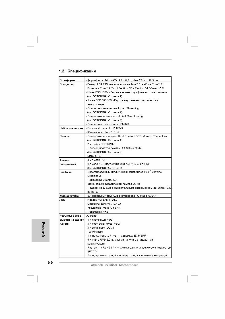
ASRock 775i65G Motherboard6 66 66 66 66 6
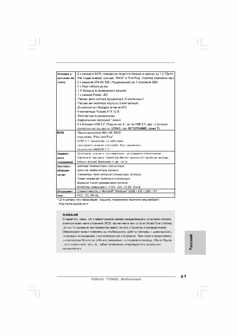
6 76 76 76 76 7ASRock 775i65G Motherboard

ASRock 775i65G Motherboard6 86 86 86 86 8

6 96 96 96 96 9ASRock 775i65G Motherboard

ASRock 775i65G Motherboard7 07 07 07 07 0
Short Open
JL JR
CMOS
JR1 JL1
2_31_2
CMOS
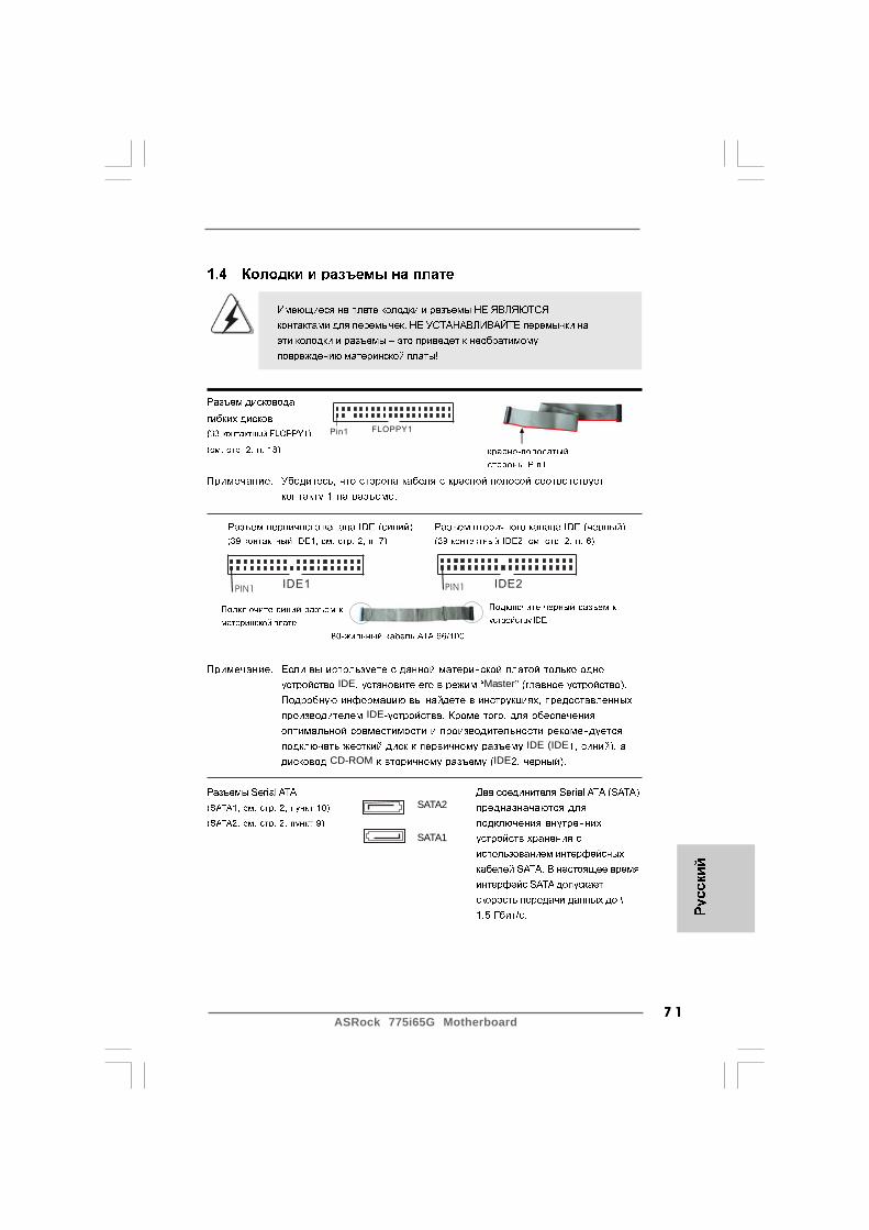
7 17 17 17 17 1ASRock 775i65G Motherboard
IDE1PIN1 IDE2PIN1
SATA2
SATA1
FLOPPY1Pin1
IDE Master
IDE
IDE (IDECD-ROM IDE
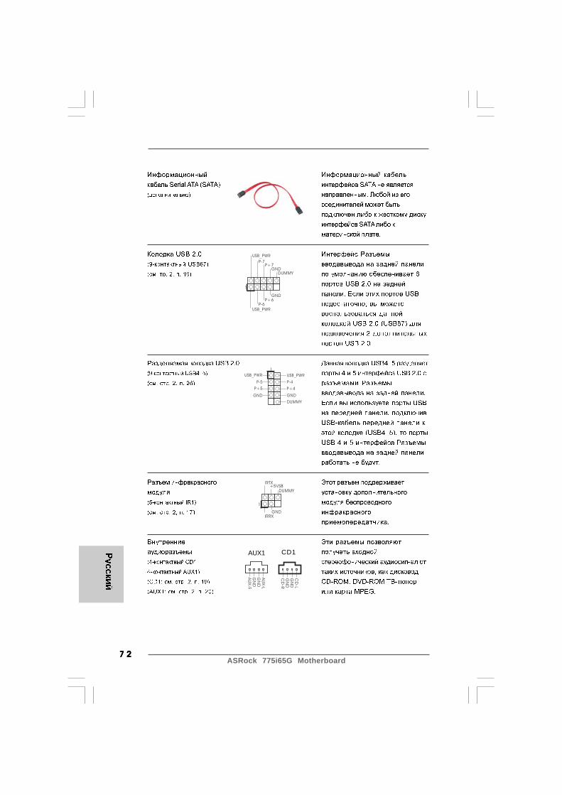
ASRock 775i65G Motherboard7 27 27 27 27 2
USB_PWR
USB_PWR
P+7P-7
P+6P-6
GND
GND
DUMMY
1
USB_PWR
1
P-5
GND
DUMMY
USB_PWR
P+5
GND
P-4
P+4
1
IRTX
IRRXGND
+5VSBDUMMY
CD
-L
GN
DG
ND
CD
-R
AU
X-L
GN
DG
ND
AU
X-R
CD1AUX1

7 37 37 37 37 3ASRock 775i65G Motherboard
GND
AUD-OUT-L
1
BACKOUT-R
GND
AUD-OUT-RMIC-POWER
MIC
BACKOUT-L
GND
+12VCHA_FAN_SPEED
+5V
DUMMYDUMMY
SPEAKER
1
GND
PWRBTN#PLED-
PLED+
DUMMYRESET#
GND
HDLED+HDLED-
1
1
PLED+
PLED+
PLED-
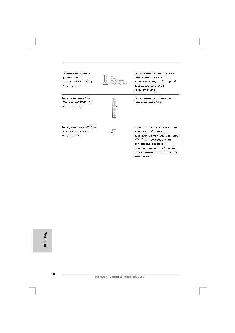
ASRock 775i65G Motherboard7 47 47 47 47 4
ATXATX.
12V-ATX ,
ATX 12 ,
.
.
GND
+12V
CPU_FAN_SPEED
FAN_SPEED_CONTROL

7 57 57 57 57 5ASRock 775i65G Motherboard

ASRock 775i65G Motherboard7 67 67 67 67 6
Portu
gu
ês
Portu
gu
ês
Portu
gu
ês
Portu
gu
ês
Portu
gu
ês
1. Introdução1. Introdução1. Introdução1. Introdução1. IntroduçãoGratos por comprar nossa placa–mãe 775i65G, um produto confiável feito comASRock um estrito controle de qualidade consistente. Com um excelentedesempenho, essa placa é dotada de um projeto robusto que atende a ASRock decompromisso com a qualidade e durabilidade.Este Guia de Instalação Rápida apresenta a placa-mãe e o guia de instalaçãopasso a passo. Mais informações detalhadas sobre a placa-mãe podem serencontradas no manual do usuário do CD de suporte.
Porque as especificações da placa mãe e o software de BIOSpoderiam ser atualizados, o conteúdo deste manual pode sercambiado sem aviso. Em caso de qualquer modificação destemanual, a versão atualizada estará disponível no website de ASRocksem prévio aviso. Pode também encontrar as listas das mais recentesplacas VGA e das CPUs suportadas no site da web da ASRock.Website de ASRock http://www.asrock.comSe precisar de apoio técnico em relação a este placa-mãe, por favorvisite o nosso sítio da internet para informação específica acerca domodelo que está a utilizar.www.asrock.com/support/index.asp
1.1 Este pacote contém1.1 Este pacote contém1.1 Este pacote contém1.1 Este pacote contém1.1 Este pacote contémPlaca-mãe ASRock 775i65G
(Formato Micro ATX: 9,6 pol. x 8,0 pol., 24,4 cm x 20,3 cm)Guia de instalação rápida da ASRock 775i65GCD de suporte da placa ASRock 775i65GUm cabo-fita IDE Ultra ATA 66/100 de 80 condutoresUm cabo de dados ATA Serial (SATA) (Opcional)Uma proteção I/O

7 77 77 77 77 7ASRock 775i65G Motherboard
1.2 Especificações1.2 Especificações1.2 Especificações1.2 Especificações1.2 Especificações
Plataforma - Formato Micro ATX: 9,6 pol. x 8,0 pol., 24,4 cm x 20,3 cm CPU - Socket Intel® Dual-Core CoreTM 2 Extreme / CoreTM 2 Duo /
Pentium® D / Pentium® 4 / Celeron® D de 775 pinos- FSB de 1066 MHz para gráficos externos (veja o AVISO 1)- FSB de 800/533 MHz para gráficos internos- Suporta a tecnologia Hyper-Threading (veja o AVISO 2)- Suporta a tecnologia Untied Overclocking (veja o AVISO 3)- Suporta a CPU EM64T
Chipsets - North Bridge: Intel® 865G- South Bridge: Intel® ICH5
Memória - Suporte à tecnologia de memória de duplo canal (veja o AVISO 4)- 2 x slots de DDR DIMM- Suporte DDR400/333/266 (veja o AVISO 5)- Máx. 2GB
Slots de Expansão - 3 x slots de PCI- 1 x slot AGP, suporta 1.5V, placas AGP 8X/4X (veja o AVISO 6)
VGA integrado - Intel® Extreme Graphics 2 incluído- DirectX 8.0 VGA- Memória partilhada máxima 96MB- Suporta D-Sub com resolução máxima até 2048x1536 @ 75 Hz
Áudio - Áudio de canal 5.1 (Codec de áudio C-Media 9761A) LAN - Realtek PCI LAN 8101L
- Velocidade: 10 / 100 Ethernet- Suporta Wake-On-LAN- Suporta PXE
Entrada/Saída I/O Panel pelo painel - 1 x porta para mouse PS/2 traseiro - 1 x porta para teclado PS/2
- 1 x porta serial: COM1- 1 x porta VGA- 1 x porta paralela (com suporte ECP/EPP)- 6 x portas USB 2.0 padrão- 1 x porta LAN RJ-45 com LED (LED VELOCIDADE)- Áudio Jack: saída / entrada de linha / microfone + porta de jogos
Port
ug
uê
sPo
rtu
gu
ês
Port
ug
uê
sPo
rtu
gu
ês
Port
ug
uê
s

ASRock 775i65G Motherboard7 87 87 87 87 8
Portu
gu
ês
Portu
gu
ês
Portu
gu
ês
Portu
gu
ês
Portu
gu
ês
Conectores - 2 x conectores SATA, suporte a taxa de transferência de dados de até 1,5 Gb/s (Serial Não suporta as funções “RAID” e “conexão a quente”)- 2 x conectores ATA100 IDE (suporta até 4 dispositivos IDE)- 1 x porta para disquete- 1 x conector do módulo de infravermelho- 1 x conector do LED de alimentação- Conector do ventilador da CPU (4 pinos)- Conector do ventilador da chassis (3 pinos)- Conector de força do ATX de 20 pinos- Conector ATX 12 V de 4 pinos- Conectores internos de áudio- Conector Áudio do painel frontal- 2 x cabezal USB 2.0 (suporta 4 portas USB 2.0; 2 delas são partilhadas através da especificação USB45) (veja o AVISO 7)
BIOS - 4Mb BIOS AMI- Suporta dispositivos “Plug and Play”- ACPI 1.1 atendendo a eventos de “wake up”- Suporta dispositivos sem jumper- Suporte para SMBIOS 2.3.1
CD de suporte - Controladores, utilitários, software antivírus (Experimentacao Versao), CyberLink MediaEspresso 6.5 versão de demonstração, ASRock MAGIX Multimedia Suite - OEM
Funcionalidade - ASRock APP Charger (veja o AVISO 8) Única - Booster híbrido:
- Frequência da CPU com controle contínuo (veja o AVISO 9)- ASRock U-COP (veja o AVISO 10)- B.F.G. (Boot Failure Guard)
Monitor do HW - Sensores de temperature do procesador- Medição de temperatura da placa-mãe- Tacômetros de ventilador do Processador- Tacômetros de ventilador do chassis- Ventoinha silenciosa para a CPU- Monitoramento de voltagem : +12 V, +5 V, +3.3 V, Vcore
Sistema - Microsoft® Windows® 98SE / ME / 2000 / XP Operacional Certificações - FCC, CE, WHQL* Para informações mais detalhadas por favor visite o nosso sítio Web: http://www.asrock.com

7 97 97 97 97 9ASRock 775i65G Motherboard
AVISO!1. A CPU FSB1066 apenas é suportada aquando da instalação da placa
VGA AGP na ranhura AGP. Para além disso, se utilizar uma CPUFSB1066 nesta placa principal, deve adoptar um módulo de memóriaDDR400 CL2.5.
2. Sobre a configuração da “Tecnologia Hyper-Threading”, consulte apágina 29 do Manual do Usuário no CD de suporte. (Somenteinglês)
3. Esta placa principal suporta a tecnologia Untied Overclocking.Consulte a secção “Tecnologia Untied Overclocking” na página 19para mais informações.
4. Esta placa-mãe suporta a tecnologia de memória de duplo canal. Antesde implementar a tecnologia de memória de duplo canal, certifique-sede ler o guia de instalação dos módulos de memória na página 13para a instalação correta.
5. Veja na tabela abaixo a freqüência de suporte de memória e acorrespondente freqüência FSB do processador.Freqüência FSB do processador Freqüência de suporte de memória
800 DDR266, DDR320*, DDR400533 DDR266, DDR333
* Ao usar um processador FSB800 nesta placa-mãe, o mesmo funcionaráa DDR320 caso seja adotado um módulo de memória DDR333.
6. NAO ligue as placas maes 775i65G! Com vga’s de 3.3V no slot AGPPodera causar dano permanente, e CAUSAR PERCA DA GARANTIA.
7. Power Management para USB 2.0 funciona bem embaixo deMicrosoft® Windows® XP SP1; SP2/2000 SP4. É possível que nãotrabalhe corretamente embaixo de Microsoft 98/ME.
AVISOTenha em atenção que a operação de overclocking envolve alguns riscos,nomeadamente no que diz respeito ao ajuste das definições do BIOS, à aplicação datecnologia Untied Overclocking ou à utilização de ferramentas de overclocking deterceiros. O overclocking pode afectar a estabilidade do seu sistema ou até mesmocausar danos ao nível dos componentes e dispositivos que integram o sistema. Estaoperação é da total responsabilidade do utilizador. Não nos responsabilizamos pelospossíveis danos resultantes do overclocking.
Port
ug
uê
sPo
rtu
gu
ês
Port
ug
uê
sPo
rtu
gu
ês
Port
ug
uê
s

ASRock 775i65G Motherboard8 08 08 08 08 0
Portu
gu
ês
Portu
gu
ês
Portu
gu
ês
Portu
gu
ês
Portu
gu
ês
8. Se pretende carregar os seus dispositivos Apple, como o iPhone/iPod/iPad Touch, de forma mais rápida e menos limitada, a ASRockpreparou para si uma solução fantástica, o ASRock APP Charger.Instale o controlador APP Charger para que o seu iPhone carreguemais rapidamente a partir do computador, até 40% mais rápido doque antes. O ASRock APP Charger permite-lhe carregar rapidamentevários dispositivos Apple em simultâneo e suporta até ocarregamento quando o seu PC entrar em modo de Espera (S1),Hibernação (S4) ou desligado (S5). Com o controlador APP Chargerinstalado, poderá desfrutar facilmente da melhor experiência decarregamento.Web site da ASRock: http://www.asrock.com/Feature/AppCharger/index.asp
9. Apesar de esta placa-mãe oferecer controle continuamente variável,não se recomenda efetuar over-clock. Freqüências de barramentodiferentes das recomendadas para a CPU podem provocarinstabilidade do sistema ou danos à CPU.
10. Assim que se detecta um superaquecimento na CPU, o sistema sedesliga automaticamente e o botão de energia do chassis ficainativo.Cheque o ventilador da CPU na placa–mãe, para verificar seestá funcionando corretamente antes de religar o sistema. Paramelhorar a dissipação de calor, lembre-se de aplicar o material deinterface térmica entre o processador e o dissipador de calor.
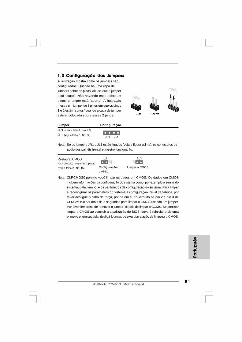
8 18 18 18 18 1ASRock 775i65G Motherboard
Port
ug
uê
sPo
rtu
gu
ês
Port
ug
uê
sPo
rtu
gu
ês
Port
ug
uê
s
1.3 Configuração dos Jumpers1.3 Configuração dos Jumpers1.3 Configuração dos Jumpers1.3 Configuração dos Jumpers1.3 Configuração dos JumpersA ilustração mostra como os jumpers sãoconfigurados. Quando há uma capa dejumpers sobre os pinos, diz–se que o jumperestá “curto”. Não havendo capa sobre ospinos, o jumper está “aberto”. A ilustraçãomostra um jumper de 3 pinos em que os pinos1 e 2 están “curtos” quando a capa de jumperestiver colocada sobre esses 2 pinos.
Jumper ConfiguraçãoJR1 (veja a folha 2, No. 22)
JL1 (veja a folha 2, No. 22)
Nota: Se os jumpers JR1 e JL1 estão ligados (veja a figura acima), os conectores deáudio dos painéis frontal e traseiro funcionarão.
Restaurar CMOS(CLRCMOS0, jumper de 3 pinos)
(veja a folha 2, No. 15)
Nota: CLRCMOS0 permite você limpar os dados em CMOS. Os dados em CMOSincluem informações da configuração do sistema como: por exemplo a senha dosistema, data, tempo, e os parámetros da configuração do sistema. Para limpare reconfigurar os parámetros do sistema a configuração inicial da fábrica, porfavor desligue o cabo de força, ponha em curto–circuito os pin 2 e pin 3 deCLRCMOS0 por mais de 5 segundos para limpar o CMOS usando um jumper.Por favor lembrese de remover o jumper depois de limpar o COMS. Se precisarlimpar o CMOS ao concluir a atualização do BIOS, deverá reiniciar o sistemaprimeiro e, em seguida, desligá-lo antes de executar a ação de limpeza o CMOS.
JR1 JL1
2_31_2
Configuração-padrão
Limpar o CMOS

ASRock 775i65G Motherboard8 28 28 28 28 2
FLOPPY1Pin1
IDE1PIN1IDE2PIN1
SATA2
SATA1
1.4 Conectores da placa1.4 Conectores da placa1.4 Conectores da placa1.4 Conectores da placa1.4 Conectores da placa
Os conectores da placa NÃO são jumpers. NÃO coloque pontos dejumpers sobre esses conectores. A colocação de pontos de jumpersobre os conectores causará danos irreversíveis à placa-mãe.
Conector Figura DescriçãoConector FDD(FLOPPY 1 de 33 pinos)
(veja a folha 2, No. 18)
Nota: Certifique-se de que o lado com listras vermelhas no cabo seja conectado aolado Pino 1 do conector.
Conector primário (azul) Conector secundário de IDE (preto)(IDE1 de 39 pinos, veja a folha 2, No. 7) (IDE2 de 39 pinos, veja a folha 2, No. 6)
Ligue esta ponta (azul) Ligue esta ponta (preta)à placa–mãe aos dispositivos IDE
Cabo ATA 66/100 de 80 condutores
Nota: Se for usado apenas um dispositivo IDE nesta placa-mãe, configure-o como“Master”. Para detalhes, consulte as instruções do fornecedor do seu dispositivoIDE. Ainda, para otimizar a compatibilidade e o desempenho, conecte a unidadede disco rígido ao conector IDE primário (IDE1, azul) e a unidade de CD-ROMao conector IDE secundário (IDE2, preto).
Conectores ATA Serial Estes dois conectores Serial(SATA1: veja a folha 2, No. 10) ATA (SATA) suportam cabos(SATA2: veja a folha 2, No. 9) de dados SATA para os
dispositivos dearmazenamentos internos. Aatual interface SATA permiteuma taxa de transferência dedados de até 1.5 Gb/s.
o lado com listras vermelhas para oPino 1
Portu
gu
ês
Portu
gu
ês
Portu
gu
ês
Portu
gu
ês
Portu
gu
ês

8 38 38 38 38 3ASRock 775i65G Motherboard
USB_PWR
USB_PWR
P+7P-7
P+6P-6
GND
GND
DUMMY
1
USB_PWR
1
P-5
GND
DUMMY
USB_PWR
P+5
GND
P-4
P+4
1
IRTX
IRRXGND
+5VSBDUMMY
Port
ug
uê
sPo
rtu
gu
ês
Port
ug
uê
sPo
rtu
gu
ês
Port
ug
uê
s
Cabo de dados Tanto a saída do cabo deSerial ATA (SATA) dados SATA pode ser(opcional) conectado ao disco rígido
SATA quanto o conector SATAna placa mãe.
Conector USB 2.0 Entrada/Saída pelo painel(USB67 de 9 pinos) traseiro conta com 6 portas USB(veja a folha 2, No. 16) 2.0 padrão no painel traseiro. Se
as portas USB traseiras foreminsuficientes, este conectorUSB 2.0 (USB67) est disponívele suporta mais duas portasUSB 2.0.
Conector USB 2.0 Este conector USB4_5 écompartilhado compartilhado com as portas(USB4_5 de 9 pinos) USB 2.0 núm. 4 e 5 na Entrada/(veja a folha 2, No. 26) Saída pelo painel traseiro. Ao
usar as portas USB do painelfrontal conectando o respectivocabo USB a este conector(UBS4_5), as portas USB núm.4 e 5 na Entrada/Saída pelopainel traseiro não funcionarão.
Conector do módulo Este conector suporta umde infravermelho módulo de infravermelho para(IR1 de 5 pinos) transmissão e recepção sem(veja a folha 2, No. 17) fio, opcional.
Conectores internos de áudio Estes conectores permitem(CD1 de 4 pinos, que se receba entrada deAUX1 de 4 pinos) áudio em estéreo de fontes(CD1: veja a floha 2, No. 19) de áudio como CD-ROM,(AUX1: veja a floha 2, No. 20) DVD-ROM, placa sintonizadora
de TV ou placa MPEG.
CD
-L
GN
DG
ND
CD
-R
AU
X-L
GN
DG
ND
AU
X-R
CD1AUX1

ASRock 775i65G Motherboard8 48 48 48 48 4
+5V
DUMMYDUMMY
SPEAKER
1
GND
PWRBTN#PLED-
PLED+
DUMMYRESET#
GND
HDLED+HDLED-
1
1
PLED+
PLED+
PLED-
Conector AC’97 Áudio do painel Esta é uma interface para ofrontal cabo de áudio no painel frontal,(AUDIO1 de 8 pinos) que permite uma conexão e(veja a folha 2, No. 21) controle convenientes dos
dispositivos de áudio.
Conector do painel do sistema Este conector acomoda várias(PANEL1 de 9 pinos) funções do painel frontal do(veja a folha 2, No. 12) sistema.
Conector do alto-falante do chassi Ligue o alto-falante do chassi(SPEAKER1 de 4 pinos) neste conector.(veja a folha 2, No. 14)
Conector do LED de alimentação Ligue o LED de alimentação do(PLED1 de 3 pinos) chassis a este conector para(veja a folha 2, No. 13) indicar o estado de alimentação
do sistema. O LED ficaráacesso quando o sistemaestiver em funcionamento. OLED fica intermitente no estadoS1. O LED fica desligadonos estados S4 ou no estadoS5 (desligado).
Conector do ventilador do chassi Ligue o cabo do ventilador(CHA_FAN1 de 3 pinos) neste conector, coincidindo o(veja a folha 2, No. 11) fio preto com o pino de
aterramento.
1. A especificação +5 VA é utilizada apenas em termos do áudio, não utilize qualquer outra fonte de alimentação como, por exemplo, a USB.2. O painel frontal de áudio de alta definição (Azalia) e o painel frontal de áudio AC’97 estão definidos de forma diferente em termos dos pinos. A incorrecta ligação do painel frontal de áudio e do respectivo conector pode causar danos permanentes nesta placa principal.
Portu
gu
ês
Portu
gu
ês
Portu
gu
ês
Portu
gu
ês
Portu
gu
ês
GND
PWRBTN#PLED-
PLED+
DUMMYRESET#
GND
HDLED+HDLED-
1
GND
+12VCHA_FAN_SPEED
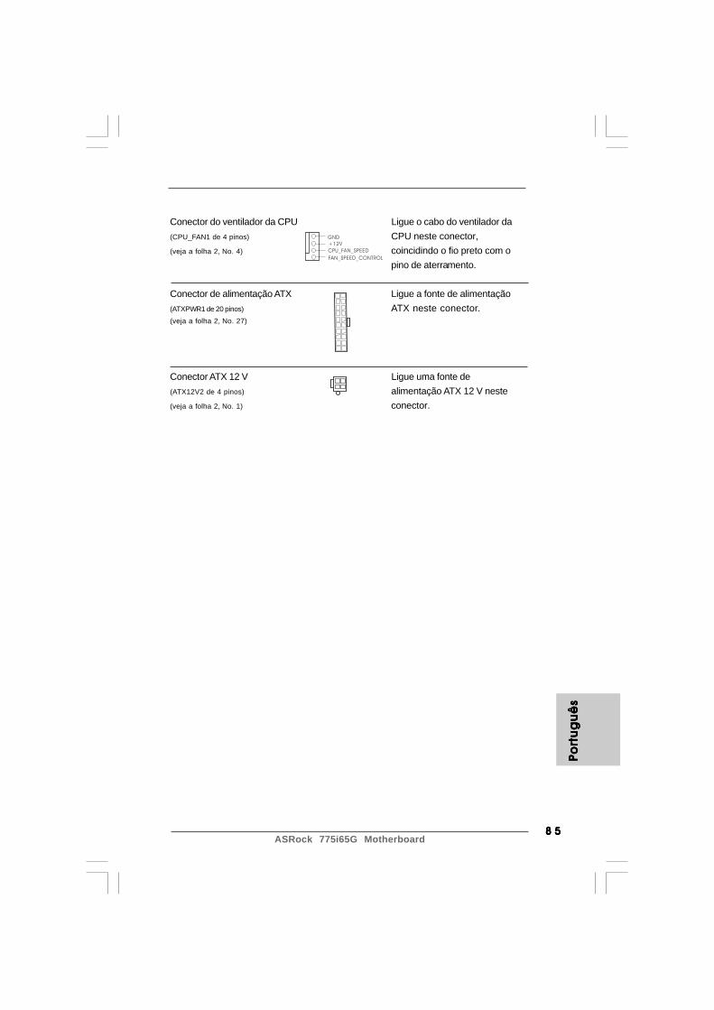
8 58 58 58 58 5ASRock 775i65G Motherboard
GND
+12V
CPU_FAN_SPEED
FAN_SPEED_CONTROL
Port
ug
uê
sPo
rtu
gu
ês
Port
ug
uê
sPo
rtu
gu
ês
Port
ug
uê
s
Conector do ventilador da CPU Ligue o cabo do ventilador da(CPU_FAN1 de 4 pinos) CPU neste conector,(veja a folha 2, No. 4) coincidindo o fio preto com o
pino de aterramento.
Conector de alimentação ATX Ligue a fonte de alimentação(ATXPWR1 de 20 pinos) ATX neste conector.(veja a folha 2, No. 27)
Conector ATX 12 V Ligue uma fonte de(ATX12V2 de 4 pinos) alimentação ATX 12 V neste(veja a folha 2, No. 1) conector.
ASRock 775i65G Motherboard8 68 68 68 68 6
2. Informações da BIOS2. Informações da BIOS2. Informações da BIOS2. Informações da BIOS2. Informações da BIOSO Utilitário de Configuração do BIOS está armazenado no chip FWH do BIOS. Aoiniciar o computador, pressione <F2> durante o Autoteste de iniciação (POST)para acessar o Utilitário de Configuração do BIOS; caso contrário, o POSTcontinuará com as rotinas de teste. Se desejar acessar o Utilitário deConfiguração do BIOS depois do POST, reinicie o sistema pressionando <Ctl> +<Alt> + <Del>, ou pressionando o botão de reinício no chassi do sistema. Para asinformações detalhadas sobre o Utilitário de Configuração do BIOS, consulte oManual do Usuário (arquivo PDF) no CD de suporte.
3. Informações do CD de Suporte3. Informações do CD de Suporte3. Informações do CD de Suporte3. Informações do CD de Suporte3. Informações do CD de SuporteEsta placa Mãe suporta vários sistemas operacionais: Microsoft® Windows®: 98SE /ME / 2000 / XP. O CD de instalação que acompanha a placa Mãe contem: drivers eutilitários necessários para um melhor desempenho da placa Mãe. Para começar ausar o CD de instalação, introduza o CD na leitora de CD-ROM do computador.Automaticamente iniciará o menu principal, casa o AUTORUN esteja ativado. Se omenu principal não aparecer automaticamente, explore o CD e execute o“ASSETUP.EXE” localizado na pasta BIN.
Portu
gu
ês
Portu
gu
ês
Portu
gu
ês
Portu
gu
ês
Portu
gu
ês

8 78 78 78 78 7ASRock 775i65G Motherboard
Türk
çe
Türk
çe
Türk
çe
Türk
çe
Türk
çe

ASRock 775i65G Motherboard8 88 88 88 88 8
Türkç
eTü
rkçe
Türkç
eTü
rkçe
Türkç
e

8 98 98 98 98 9ASRock 775i65G Motherboard
Türk
çe
Türk
çe
Türk
çe
Türk
çe
Türk
çe

ASRock 775i65G Motherboard9 09 09 09 09 0
Türkç
eTü
rkçe
Türkç
eTü
rkçe
Türkç
e

9 19 19 19 19 1ASRock 775i65G Motherboard
Türk
çe
Türk
çe
Türk
çe
Türk
çe
Türk
çe

ASRock 775i65G Motherboard9 29 29 29 29 2
Türkç
eTü
rkçe
Türkç
eTü
rkçe
Türkç
e
OpenShort
JR1 JL1
2_31_2
Standart

9 39 39 39 39 3ASRock 775i65G Motherboard
FLOPPY1Pin1
Türk
çe
Türk
çe
Türk
çe
Türk
çe
Türk
çe
IDE1PIN1 IDE2PIN1
SATA2
SATA1

ASRock 775i65G Motherboard9 49 49 49 49 4
GND
AUD-OUT-L
1
BACKOUT-R
GND
AUD-OUT-RMIC-POWER
MIC
BACKOUT-L
CD
-L
GN
DG
ND
CD
-R
AU
X-L
GN
DG
ND
AU
X-R
CD1AUX1
USB_PWR
1
P-5
GND
DUMMY
USB_PWR
P+5
GND
P-4
P+4
Türkç
eTü
rkçe
Türkç
eTü
rkçe
Türkç
e
USB_PWR
USB_PWR
P+7P-7
P+6P-6
GND
GND
DUMMY
1
1
IRTX
IRRXGND
+5VSBDUMMY
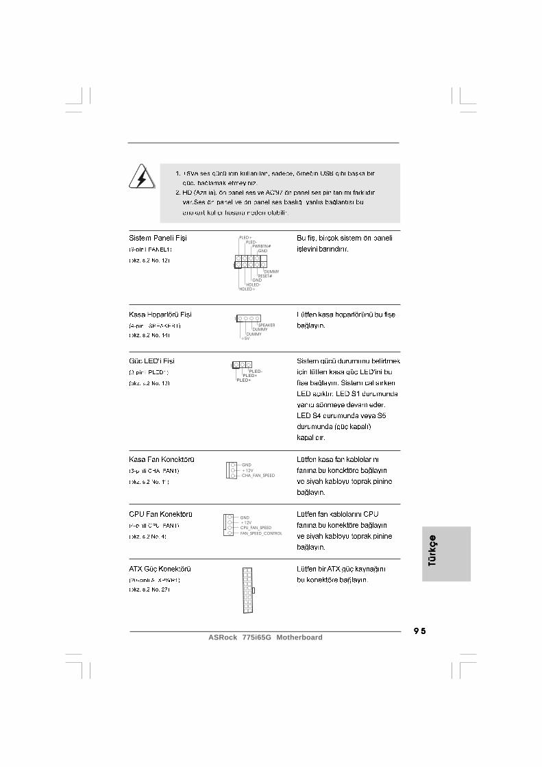
9 59 59 59 59 5ASRock 775i65G Motherboard
GND
+12VCHA_FAN_SPEED
+5V
DUMMYDUMMY
SPEAKER
1
GND
PWRBTN#PLED-
PLED+
DUMMYRESET#
GND
HDLED+HDLED-
1
GND
+12V
CPU_FAN_SPEED
FAN_SPEED_CONTROL
1
PLED+
PLED+
PLED-
Türk
çe
Türk
çe
Türk
çe
Türk
çe
Türk
çe
ASRock 775i65G Motherboard9 69 69 69 69 6
Türkç
eTü
rkçe
Türkç
eTü
rkçe
Türkç
e

9 79 79 79 79 7ASRock 775i65G Motherboard
Türk
çe
Türk
çe
Türk
çe
Türk
çe
Türk
çe