Embed Size (px)
Citation preview

Copyright © National Fire Protection Association 2013. All rights reserved. This copy is solely for your personal, noncommercial use in connection with participation in the NFPA Standards Development Process. Except for limited hard copies reasonably necessary for such use, this copy may not be reproduced or redistributed. For additional copies of this and other downloadable reports related to the NFPA Standards Development Process visit www.nfpa.org.
1 Balloting Version: First Draft Proposed 2014 Edition NFPA 82
Balloting Version First Draft NFPA® 82 Standard on
Incinerators and Waste and Linen Handling Systems and Equipment Proposed 2014 Edition
About This Document: This document is the Balloting Version of the First Draft of the proposed 2014 edition of NFPA 82. It has been compiled by NFPA staff for the purpose of balloting by the responsible Technical Committee(s) in accordance with the Regulations Governing the Development of NFPA Standards ("Regs.") This Balloting Version of the First Draft incorporates the changes made through First Revisions developed by the Technical Committee at its First Draft Meeting, and it is made available to Technical Committee members for their review during balloting. Only First Revisions that Pass the Technical Committee ballot will be included in the Final First Draft that will be published for public review. See, generally, Regs. at Section 4.3, Committee Activities: Input Stage.
FIRS
T DR
AFT

2 Balloting Version: First Draft Proposed 2014 Edition NFPA 82
Chapter 1 Administration
1.1 Scope.
1.1.1 This standard covers requirements for the installation, maintenance, and use of waste and
recyclables storage rooms, containers, handling systems, incinerators, compactors, and linen and
laundry handling systems.
1.1.2 This standard does not include design criteria for the purpose of reducing air pollution.
For such criteria, consult the authorities having jurisdiction.
1.1.3 The requirements in this standard shall not apply to one- or two-family residential
structures.
1.2 Purpose. (Reserved)
1.3* Application. This standard shall be applied to new construction and new equipment, as
determined by the authority having jurisdiction.
1.4 Retroactivity. This standard shall not require the alteration or replacement of existing
construction or equipment currently in use, provided that the owner establishes appropriate
administrative, maintenance, and training programs that provide equivalent safety.
1.5 Equivalency. Nothing in this standard is intended to prevent the use of new methods or
devices of equivalent or superior quality, strength, fire resistance, effectiveness, durability, and
safety over those prescribed by this standard.
1.5.1 Technical documentation shall be submitted to the authority having jurisdiction to
demonstrate equivalency.
1.5.2 The system, method, or device shall be approved for the intended purpose by the
authority having jurisdiction.
Chapter 2 Referenced Publications
2.1 General. The documents or portions thereof listed in this chapter are referenced within this
standard and shall be considered part of the requirements of this document.
First Revision No. 1:NFPA 82-2009 [FR 17: FileMaker]
2.2 NFPA Publications. National Fire Protection Association, 1 Batterymarch Park, Quincy, MA 02169-7471. NFPA 13, Standard for the Installation of Sprinkler Systems, 200713 edition. NFPA 31, Standard for the Installation of Oil-Burning Equipment, 200611 edition. NFPA 54, National Fuel Gas Code, 200912 edition. NFPA 58, Liquefied Petroleum Gas Code, 200811 edition. NFPA 70 NFPA 70®, National Electrical Code®, 200811 edition. NFPA 80, Standard for Fire Doors and Other Opening Protectives, 2013 edition. FI
RST
DRAF
T

3 Balloting Version: First Draft Proposed 2014 Edition NFPA 82
NFPA 90A, Standard for the Installation of Air-Conditioning and Ventilating Systems, 200912 edition. NFPA 211, Standard for Chimneys, Fireplaces, Vents, and Solid Fuel–Burning Appliances, 200613 edition. NFPA 259, Standard Test Method for Potential Heat of Building Materials, 200813 edition. NFPA 5000 NFPA 5000®, Building Construction and Safety Code®, 200912 edition.
2.3 Other Publications.
First Revision No. 2:NFPA 82-2009 [FR 5: FileMaker]
2.3.1 ASTM Publications. ASTM International, 100 Barr Harbor Drive, P.O. Box C700, West Conshohocken, PA 19428-2959. ASTM C 27, Standard Classification for Fireclay and High-Alumina Refractory Brick, 1998 (2008) 1993. ASTM C 199, Standard Test Method for Pier Test for Refractory Mortars, 1984 (2011) 1994.
First Revision No. 39:NFPA 82-2009
[FR 5: FileMaker] 2.3.2 ASHRAE Publications. American Society of Heating, Refrigerating and Air Conditioning Engineers, Inc., 1791 Tullie Circle, N.E., Atlanta, GA 30329. ASHRAE Handbook ASHRAE Handbook, —HVAC Systems and Equipment, 200008. 2.3.3 Other Publications. Merriam-Webster’s Collegiate Dictionary, 11th edition, Merriam-Webster, Inc., Springfield, MA, 2003.
First Revision No. 40:NFPA 82-2009 [FR 5: FileMaker]
2.4 References for Extracts in Mandatory Sections. NFPA 33, Standard for Spray Application Using Flammable or Combustible Materials, 2007 edition.
Chapter 3 Definitions
3.1 General. The definitions contained in this chapter shall apply to the terms used in this
standard. Where terms are not defined in this chapter or within another chapter, they shall be
defined using their ordinarily accepted meanings within the context in which they are used.
Merriam-Webster’s Collegiate Dictionary, 11th edition, shall be the source for the ordinarily
accepted meaning.
3.2 NFPA Official Definitions.
FIRS
T DR
AFT

4 Balloting Version: First Draft Proposed 2014 Edition NFPA 82
3.2.1* Approved. Acceptable to the authority having jurisdiction.
3.2.2* Authority Having Jurisdiction (AHJ). An organization, office, or individual
responsible for enforcing the requirements of a code or standard, or for approving equipment,
materials, an installation, or a procedure.
3.2.3 Labeled. Equipment or materials to which has been attached a label, symbol, or other
identifying mark of an organization that is acceptable to the authority having jurisdiction and
concerned with product evaluation, that maintains periodic inspection of production of labeled
equipment or materials, and by whose labeling the manufacturer indicates compliance with
appropriate standards or performance in a specified manner.
3.2.4* Listed. Equipment, materials, or services included in a list published by an organization
that is acceptable to the authority having jurisdiction and concerned with evaluation of products
or services, that maintains periodic inspection of production of listed equipment or materials or
periodic evaluation of services, and whose listing states that either the equipment, material, or
service meets appropriate designated standards or has been tested and found suitable for a
specified purpose.
3.2.5 Shall. Indicates a mandatory requirement.
3.2.6 Should. Indicates a recommendation or that which is advised but not required.
3.2.7 Standard. A document, the main text of which contains only mandatory provisions using
the word “shall” to indicate requirements and which is in a form generally suitable for mandatory
reference by another standard or code or for adoption into law. Nonmandatory provisions shall
be located in an appendix or annex, footnote, or fine-print note and are not to be considered a
part of the requirements of a standard.
3.3 General Definitions.
3.3.1 Chute.
3.3.1.1 General Access Chute. Chute capable of being accessed by the general public with no
restriction on use.
3.3.1.2* Gravity Waste or Linen Chute. An enclosed vertical passageway (riser) in a building,
used for transferring trash or linen by gravity to a room at the bottom or to an interface to a
compactor.
3.3.1.3 Limited Access Chute. Chute not capable of being accessed by the general public with a
restriction on use to authorized personnel.
3.3.2 Combustible. Capable of undergoing combustion.
First Revision No. 3:NFPA 82-2009 [FR 2: FileMaker]
3.3.3 Door.
FIRS
T DR
AFT

5 Balloting Version: First Draft Proposed 2014 Edition NFPA 82
3.3.3.1 Gravity Chute Intake Door. The door used to deposit waste or linen directly into the chute of a gravity or pneumatic system. 3.3.3.2 Chute Discharge Door. The door used at the termination of a waste or linen chute of a gravity or pneumatic system. Pneumatic Chute Loading Door. The door used to deposit waste or linen directly into the chute of a pneumatic system.
3.3.4 General Access Chute. See 3.3.1.1.
3.3.5 Gravity Chute Intake Door. See 3.3.3.1.
3.3.6 Gravity Waste or Linen Chute. See 3.3.1.2.
3.3.7* Incinerator. Equipment predominantly designed for burning solid waste.
3.3.8 Limited Access Chute. See 3.3.1.3.
First Revision No. 4:NFPA 82-2009 [FR 18: FileMaker]
3.3.9* Limited Combustible. A building construction material not complying with the definition of noncombustible material that, in the form in which it is used, has a potential heat value not exceeding 3500 Btu/lb (8141 kJ/kg), where tested in accordance with NFPA 259, Standard Test Method for Potential Heat of Building Materials, and complies with (a) or (b): (a) materials having a structural base of noncombustible material, with a surfacing not exceeding a thickness of 1⁄8 in. (3.2 mm) that has a flame spread index not greater than 50; and (b) materials, in the form and thickness used, other than as described in (a), having neither a flame spread index greater than 25 nor evidence of continued progressive combustion and of such composition that surfaces that would be exposed by cutting through the material on any plane would have neither a flame spread index greater than 25 nor evidence of continued progressive combustion. (Materials subject to increase in combustibility or flame spread index beyond the limits herein established through the effects of age, moisture, or other atmospheric condition shall be considered combustible.) [33, 2007] 3.3.10 Noncombustible. Not capable of supporting combustion.
3.3.11 Pneumatic Chute Loading Door. See 3.3.3.2.
3.3.12 Waste Compactor. A device using electro-mechanical-hydraulic means to reduce the
volume of waste and to package it in the reduced condition.
3.3.13 Waste or Linen Conveying Systems.
3.3.13.1 Full Pneumatic. A closed system consisting of loading stations with inner doors and a
fire-rated, normally locked, outer (intake) door; normally closed air damper above the topmost
loading station; transport piping, both vertical and horizontal; waste or linen collector; fan with a
fan damper; and a central process controller. FIRS
T DR
AFT

6 Balloting Version: First Draft Proposed 2014 Edition NFPA 82
3.3.13.2 Gravity Pneumatic Transport System. A combination of a gravity chute and a
horizontal pneumatic transport system. The gravity pneumatic system includes gravity chutes
with a material discharge valve at the bottom, an air source at or near the bottom of the chute, air
control dampers, horizontal piping with a pipe tee to connect to the chute, a collector, and a fan
and fan damper.
3.3.14 Waste Processing Systems and Equipment. Devices and processes used to change the
physical form or characteristics of waste.
First Revision No. 5:NFPA 82-2009
[FR 16: FileMaker] Chapter 4 General 4.1 Opening Protectives. 4.1.1 4.1.1 Where required by this standard, openings required to have a fire protection rating shall be protected by approved fire door assemblies that are installed and maintained in accordance with NFPA 80, Standard for Fire Doors and Other Opening Protectives, except as otherwise specified by this standard.
4.1.1.1 Gas-burning installations shall be in accordance with the applicable provisions of
NFPA 54, National Fuel Gas Code, and NFPA 58, Liquefied Petroleum Gas Code.
4.1.1.2 Oil-burning installations shall comply with NFPA 31, Standard for the Installation of
Oil-Burning Equipment.
4.1.1.3 Fuel burners of all incinerators shall be equipped with safety controls that will
automatically shut off the fuel supply to the burner in the event the burner fails to ignite or its
flame becomes extinguished or in the event of insufficient draft.
4.1.2 Electrical Supply. The electrical supply to an incinerator shall be installed in accordance
with NFPA 70, National Electrical Code.
4.1.3 Air for Combustion and Ventilation.
4.1.3.1 Provision shall be made for an adequate supply of air for combustion and ventilation to
enter the room in which an incinerator is located.
4.1.3.2 Fans shall be permitted to be installed to deliver air to the incinerator room, provided
they are in operation whenever the incinerator is in use.
4.1.3.3 Rooms in which incinerators are installed shall be furnished air for combustion and
ventilation by one of the following means:
(1) A screened or louvered ventilator opening or other suitable air intake, which, if
communicating to other parts of the building, is protected by an approved fire damper
(2) A duct leading from the incinerator room to the outdoors
(3) A duct leading to a boiler or furnace room cut off as prescribed in Section 4.3 and provided
with sufficient air supply for both rooms FIRS
T DR
AFT

7 Balloting Version: First Draft Proposed 2014 Edition NFPA 82
4.1.3.4 The opening or duct specified in 4.1.3.3 shall be sized so as to provide all air
requirements, including those for waste combustion, auxiliary fuel combustion, room
temperature control, and general area ventilation, where applicable.
4.1.3.5 Air ducts extending to or from an incinerator room through other parts of a building
shall be constructed and installed in accordance with NFPA 90A, Standard for the Installation of
Air-Conditioning and Ventilating Systems.
4.1.4 Spark Arresters.
4.1.4.1 Where the nature of the waste being incinerated produces fly ash emissions, the
incinerator stacks shall be protected by one of the following:
(1) Spark arresters installed on incinerator stacks
(2) A wet scrubber or other emission control system or component installed between the
incinerator and the stack such that fly ash cannot pass directly from the incinerator to the
stack
(3) Approved design and control features that prevent the entrainment of fly ash from the
incinerator to the stack under all operating conditions
4.1.4.2 The net free area of the arrester shall be not less than four times the net free area of the
outlet of the chimney flue it serves.
4.1.4.3 Arresters shall have a vertical height of not less than 1.3 times the minimum diameter
of the chimney flue or the minimum horizontal dimension of a rectangular chimney flue.
4.1.4.4 Arresters, including bolts, rivets, screws, and supporting members, shall be made of
heat- and corrosion-resistant materials.
4.1.4.5 Openings shall not permit the passage of spheres having a diameter larger than 12.7
mm (½ in.) or block the passage of spheres having a diameter of less than 9.5 mm (3⁄8 in.).
4.1.4.6 Means shall be provided for securely attaching the spark arresters to chimneys to
provide adequate support and prevent movement of the arresters.
4.1.4.7 Spark screens shall be replaceable.
4.2 Incinerators.
4.2.1 Design and Construction. The design and construction of the incinerator and all
associated components shall be such that, in service, they will not crack, warp, or otherwise fail
structurally so as to permit flame passage or emission of combustion gases or sparks into the
building.
4.2.1.1 Incinerators shall be built in accordance with the following requirements:
(1) All combustion shall take place within the combustion chamber designed for combustion
temperatures. FIRS
T DR
AFT

8 Balloting Version: First Draft Proposed 2014 Edition NFPA 82
(2) Combustion shall not take place in breaching or chimneys unless they are designed as
combustion chambers.
(3) Incinerators designed for positive pressures shall be gastight.
(4) The combustion chamber, inner walls, roofs, bridges, walls, and curtain walls shall be
constructed so as to withstand the combustion temperatures involved and shall maintain
their integrity under all operating conditions.
(5) Metal stays, lintels, or other supports shall not be exposed to the interior of the combustion
chamber.
(6) An exterior masonry casing shall be reinforced with structural steel framework, and an
exterior steel casing shall be reinforced with structural steel members such that the casing
will withstand interior thrusts from arches and be capable of supporting all doors and burner
equipment.
(7) The steel casing or framework shall be erected and set plumb before any brickwork is done.
(8) Cylindrical outer casings made of steel not less than ¼ in. (6.4 mm) thick shall not be
required to be reinforced.
(9) All incinerator structures shall be designed to comply with applicable building codes, and
consideration shall be given to the most adverse conditions of seismic, wind, dead, live,
moving, concentrated, erection, and thermal loadings; corrosion allowance; or combinations
thereof.
(10) Openings shall be provided so that all parts of the incinerator can be cleaned, including
the ash pit, the combustion chamber, the passes of separation chambers, and the incinerator
flue.
(11) Cleanouts shall be closed by tight-fitting doors or covers, securely latched, or otherwise
held in a closed position.
(12) Ash pit and combustion chamber closures and frames shall be of cast iron or equivalent,
with the frames securely attached to the incinerator.
4.2.1.2 No part of an incinerator shall be used as a wall, roof, or floor of a building.
4.2.1.3 Incinerators shall be designed with internal insulation or refractory or shall be
otherwise protected by location, guard rails, or shields such that all areas or surfaces normally
accessible to personnel shall not exceed 71.1°C (160°F).
4.2.1.4 External insulation over incinerator shells shall not be utilized in achieving the
temperature specified in 4.2.1.3, since severe thermal damage could result. Handles of operating
doors shall not exceed a 4.4°C (40°F) rise for metallic handles and a 15.6°C (60°F) rise for
nonmetallic handles.
4.2.2 Explosion Relief.
4.2.2.1 Explosion relief shall be provided.
FIRS
T DR
AFT

9 Balloting Version: First Draft Proposed 2014 Edition NFPA 82
4.2.2.2 The area of explosion relief shall be not less than 0.09 m2 (1 ft2) of relief area for every
3 m3 (100 ft3) of primary combustion chamber volume.
4.2.2.3 Where the exhaust chimney will not serve the purpose of explosion relief, a door or
panel shall be provided and arranged to allow the door or panel to return to a closed position
promptly after pressure has been released.
First Revision No. 6:NFPA 82-2009 [FR20: FileMaker]
4.2.2.4 Exhaust stack areas that typically are closed off with valving or stack caps for directing combustion-gas effluent to other process equipment, such as heat recovery boilers, cleanup equipment, or similar installations, shall not be used in the calculation of the explosion venting area specified in 4.2.1.2 4.2.2.2.
4.2.2.5 Systems equipped with wet ash–type removal modules where a water seal exists
between the outside and the incinerator chamber atmosphere and where this water seal does not
exceed the equivalent of 1.49 kPa (6 in. water column) and the interconnecting passageway
between the internal ash port and external ash removal device is vertically oriented directly
beneath the ash port without changes in direction shall be permitted to be considered to offer an
explosion relief area for the minimum required area, based on the following:
(1) The internal dimensions of the ash port
(2) The smallest internal dimensions of the connecting and vertical passageway
(3) The normal projected area of the water surface interface
4.2.2.6 Wet ash systems wherein ash is expelled by mechanical devices, necessitating a normal
change in direction of ash flow — that is, from vertical to horizontal — shall not be considered
to provide an effective explosion relief area.
4.2.2.7 All explosion relief devices shall be oriented on the incinerator chamber so as not to be
closer than 90 degrees in side elevation or plan view to the normal operator position.
4.2.2.8 All explosion relief devices shall be placed in areas generally inaccessible to normal
personnel activities and shall be properly guarded and posted with safety signs on all sides
indicating the potential safety hazard of the vent area.
4.2.3 Placement.
4.2.3.1 Incinerators shall be placed on properly designed foundations of masonry or reinforced
concrete or on noncombustible material having a fire resistance rating of not less than 3 hours,
provided such support is independent of the building construction and the load is transferred to
the ground.
4.2.3.2 All incinerator combustion chambers shall be elevated above concrete bearing surfaces
through the use of pedestals, cradles, skids, or other means to provide a minimum of 101.6 mm
(4 in.) clear air circulation space between the concrete bearing surface and the closest surface of
the underside of the combustion chamber.
FIRS
T DR
AFT

10 Balloting Version: First Draft Proposed 2014 Edition NFPA 82
4.2.3.3 Where this elevation is not practical, as in the case of large field-erected incinerators,
other equivalent means shall be provided through the use of increased insulation, natural or
forced circulation, or other methods acceptable to the authority having jurisdiction to adequately
protect the concrete bearing surfaces from thermal damage.
4.2.4 Clearances.
4.2.4.1 Incinerators shall be installed to provide a clearance to combustible material of not less
than 914 mm (36 in.) at the sides and rear, not less than 1220 mm (48 in.) above, and not less
than 2.4 m (8 ft) at the front of the incinerator.
First Revision No. 7:NFPA 82-2009 [FR 7: FileMaker]
4.2.4.2 For an incinerator encased in brick, the clearance to combustible material shall be permitted to be 914 mm (36 in.) above the incinerator and 457 mm (18 in.) at the sides and the rear of the incinerator.
4.2.4.3 A clearance of not less than 305 mm (12 in.) shall be provided from the incinerator to
the walls or ceilings of noncombustible construction.
4.2.4.4 Where it is not possible to place combustible material on the outer or upper side
thereof, a clearance of not less than 3 in. (76.2 mm) shall be permitted to be provided from
commercial and industrial incinerators to walls or ceilings of noncombustible construction.
4.2.4.5 Incinerators that are listed specifically for installation at lesser clearances than those
specified in 4.2.4.1 and 4.2.4.2 shall be installed in accordance with the conditions of such
listing, provided that, in any case, the clearances shall be sufficient to afford accessibility for
firing, cleanout, and any necessary servicing as set forth in 4.2.4.6 through 4.2.4.10.
4.2.4.6 Clearance shall be provided around the incinerator and its appurtenances to facilitate
cleaning, repairing, and servicing.
4.2.4.7 Clearance shall be provided to allow the cleanout doors to be opened completely so that
all parts of the combustion chamber, ash pit, separation chambers, and so forth, can be reached
and so that implements used for this purpose can be freely manipulated.
4.2.4.8 All dampers, gates, burners, valves, levers, and so forth, shall be accessible for repair
and adjustment or replacement.
First Revision No. 8:NFPA 82-2009 [FR 8: FileMaker]
4.2.4.9 No construction Structural members shall not be located closer than 406 mm (16 in.) to any part of an incinerator unless permitted by 4.2.4.10.
4.2.4.10 Noncombustible structural members 610 mm (24 in.) wide or less, parallel to the
incinerator, shall be permitted to be located as close as 152 mm (6 in.) to the incinerator,
provided such members do not reduce accessibility to any moving parts of the incinerator.
4.2.5 Incinerator Charging. FIRS
T DR
AFT

11 Balloting Version: First Draft Proposed 2014 Edition NFPA 82
4.2.5.1 A waste charging system and appropriate controls shall be provided to prevent the
direct discharge of flames, combustion gases, and heat from the incinerator during waste loading
operations.
4.2.5.2 Incinerators that are loaded on a batch basis, during which the charging door is not
open while waste combustion is taking place, shall not be required to have a mechanical charging
system.
4.2.5.3 The combustion chamber of an incinerator shall not be charged through the floor
immediately above such incinerator unless the charging chute is designed with dampering and
controls that would prevent the direct passage of combustion products and radiant heat through
the chute into the charging room.
4.2.5.4 The charging hood and chute shall be constructed of not less than 12 U.S. gauge steel
casing and shall be lined with not less than 114 mm (4½ in.) of firebrick (Type F, medium duty,
or the equivalent as defined in ASTM C 27, Standard Classification for Fire Clay and High-
Alumina Refractory Brick).
4.2.5.4.1 This charging hopper shall not exceed 1.8 m (6 ft) in length, measured from the floor
opening to the outside of the roof of the incinerator combustion chamber.
4.2.5.5 The charging opening shall be protected by a cover extending beyond the edges of the
opening for at least 51 mm (2 in.) on all sides and lined with not less than 63.5 mm (2½ in.) of
refractory material.
First Revision No. 29:NFPA 82-2009 [FR 1: FileMaker]
4.2.5.6 The charging-floor opening shall be located in a room with walls and floor-ceiling assemblies that have a fire resistance rating of not less than 2 hours, with openings protected by an approved self-closing or automatic-closing fire door assembly with a fire protection rating of not less than 3- hours. fire doors.
4.2.5.6.1 Doors shall be kept closed during the charging operation and at other times, except
when waste material is delivered to the room.
4.2.6 Incinerator Residue Removal.
4.2.6.1 A system and appropriate approved measures shall be provided to adequately quench or
fully contain, or both, ash residues removed from the incinerator during cleanout operations.
4.2.6.2 These shall include such features as water sprays, a wet quench pit, or a special
containment enclosure to enable ash cleanout with minimal exposure to ambient conditions.
4.2.7 Incinerator Rooms for Incinerators.
4.2.7.1 Incinerators shall be enclosed within a room separated from other parts of the building
by walls, partitions, floor, and floor-ceiling assemblies constructed of noncombustible material
and having a fire resistance rating of not less than 2 hours and used for no other purpose. FIRS
T DR
AFT
12 Balloting Version: First Draft Proposed 2014 Edition NFPA 82
4.2.7.1.1 Storage containers of waste material to be burned and building heating equipment
shall be permitted to be located in the incinerator room.
First Revision No. 32:NFPA 82-2009 [FR 1: FileMaker]
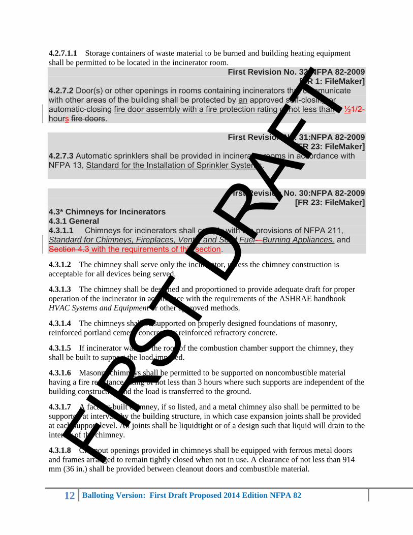
4.2.7.2 Door(s) or other openings in rooms containing incinerators that communicate with other areas of the building shall be protected by an approved self-closing or automatic-closing fire door assembly with a fire protection rating of not less than 1 ½1/2-hours fire doors.
First Revision No. 31:NFPA 82-2009 [FR 23: FileMaker]
4.2.7.3 Automatic sprinklers shall be provided in incinerator rooms in accordance with NFPA 13, Standard for the Installation of Sprinkler Systems.
First Revision No. 30:NFPA 82-2009 [FR 23: FileMaker]
4.3* Chimneys for Incinerators 4.3.1 General 4.3.1.1 Chimneys for incinerators shall comply with the provisions of NFPA 211, Standard for Chimneys, Fireplaces, Vents, and Solid Fuel-–Burning Appliances, and Section 4.3 with the requirements of this section.
4.3.1.2 The chimney shall serve only the incinerator, unless the chimney construction is
acceptable for all devices being served.
4.3.1.3 The chimney shall be designed and proportioned to provide adequate draft for proper
operation of the incinerator in accordance with the requirements of the ASHRAE handbook
HVAC Systems and Equipment or other approved methods.
4.3.1.4 The chimneys shall be supported on properly designed foundations of masonry,
reinforced portland cement concrete, or reinforced refractory concrete.
4.3.1.5 If incinerator walls or the roof of the combustion chamber support the chimney, they
shall be built to support the load imposed.
4.3.1.6 Masonry chimneys shall be permitted to be supported on noncombustible material
having a fire resistance rating of not less than 3 hours where such supports are independent of the
building construction and the load is transferred to the ground.
4.3.1.7 A factory-built chimney, if so listed, and a metal chimney also shall be permitted to be
supported at intervals by the building structure, in which case expansion joints shall be provided
at each support level. All joints shall be liquidtight or of a design such that liquid will drain to the
interior of the chimney.
4.3.1.8 Cleanout openings provided in chimneys shall be equipped with ferrous metal doors
and frames arranged to remain tightly closed when not in use. A clearance of not less than 914
mm (36 in.) shall be provided between cleanout doors and combustible material. FIRS
T DR
AFT

13 Balloting Version: First Draft Proposed 2014 Edition NFPA 82
4.3.1.9 Drains shall be provided at the base of all chimneys to allow the removal of condensed
flue products and shall be designed to avoid clogging.
4.3.1.10 Breachings shall be designed or otherwise protected in an approved manner, such as
by guard rails or shields, to protect personnel from accidental contact with surfaces that exceed
71.1°C (160°F).
4.3.1.11 External insulation shall not be used on hot breachings.
4.3.2 Listed Medium-Heat Chimneys. Listed medium-heat appliance chimneys shall be
permitted to be used and shall be installed in accordance with the conditions of the listing and the
manufacturer's instructions.
4.3.3 Metal Chimneys.
4.3.3.1 Metal chimneys shall be properly riveted or welded, securely supported, and
constructed in accordance with good engineering practice.
4.3.3.2 Metal chimneys shall be constructed of steel or cast iron. Sheet steel shall have a
thickness not less than that indicated in Table 4.3.3.2.
Table 4.3.3.2 Minimum Thickness of Sheet Steel Chimneys
Manufacturer
Standard
U.S. Gauge
Number
Minimum
Thickness
Area
Equivalent
Round Diameter
mm in. m2 in.2 mm in.
16 1.37 0.054 Up to 0.0994 Up to 154 Up to 356 Up to 14
14 1.75 0.069 0.0999–0.1296 155–201 >356–406 >14–16
12 2.49 0.098 0.1303–0.1638 202–254 >406–457 >16–18
10 3.25 0.128 >0.1638 >254 >457 >18
Note: Regardless of minimum thicknesses in this table, the thickness of sheet metal shall be adequate to meet the
requirements of 4.3.3.6.
4.3.3.3 Where secondary combustion temperatures do not exceed 982°C (1800°F), metal
chimneys shall be lined with 114 mm (4½ in.) of high-duty, spall-resistant firebrick (as defined
in ASTM C 27, Standard Classification for Fireclay and High-Alumina Refractory Brick) laid in
high-duty refractory mortar (as defined in ASTM C 199, Standard Test Method for Pier Test for
Refractory Mortars).
4.3.3.3.1 The lining shall start at the base of the chimney and extend continuously to the top.
4.3.3.3.2* Equivalent linings of equivalent thickness, such as Class A or better alumina-silica
base castable refractories or Class O or better insulating castable refractories, shall be permitted
to be used.
4.3.3.4 Where secondary combustion temperatures exceed 982°C (1800°F), metal chimneys
shall be lined with 114 mm (4½ in.) of super-duty, spall-resistant refractory brick (as defined in
FIRS
T DR
AFT
14 Balloting Version: First Draft Proposed 2014 Edition NFPA 82
ASTM C 27, Standard Classification for Fireclay and High-Alumina Refractory Brick) laid in
refractory mortar.
4.3.3.4.1 The refractory mortar shall be high-duty for temperatures up to 1500°C (2730°F) and
super-duty or better for temperatures up to 1600°C (2910°F).
4.3.3.4.2 The lining shall start at the base of the chimney and extend continuously to the top.
4.3.3.4.3* Equivalent linings of equivalent thickness, such as Class B or better alumina-silica
base castable refractories (as defined in ASTM C 27) in accordance with temperature
requirements or Class P and Class Q insulating castable refractories (as defined in ASTM C 27)
in accordance with temperature requirements, shall be permitted to be used.
4.3.3.5 Castable plastic refractories or other refractories shall be permitted to be used in metal
chimneys in lieu of firebrick, provided such refractory is of equivalent heat and corrosion
resistance.
4.3.3.5.1 Liners made of these refractories shall be supported by anchors made of corrosion-
resistant steel capable of supporting the refractory load at 727°C (1500°F).
4.3.3.5.2 The insulating value shall be such that temperatures at the supports shall not exceed
this temperature under all firing conditions.
4.3.3.6 Metal chimneys shall be properly riveted, welded, or bolted; securely supported; and
constructed in accordance with good engineering practice as necessary to achieve the following
conditions:
(1) Strength to resist stresses due to steady or gusting wind loads
(2) Adequate anchoring, bracing, and inherent strength to withstand seismic and wind-induced
vibrational stresses
(3) Proper material thickness for durability, considering fuel analysis, gas temperature, and
exposure
(4) Security against leakage of flue gases under positive pressure
(5) Allowance for thermal expansion of breaching and vertical sections
4.3.3.7 If a metal chimney extends through any story of a building above that in which the
connected incinerator is located, it shall be enclosed in such upper stories within continuous
walls that are constructed of noncombustible materials, such as masonry, and that extend from
the ceiling of the incinerator room to or through the roof so as to retain the integrity of the fire
separations as required by applicable building code provisions.
First Revision No. 9:NFPA 82-2009 [FR 22: FileMaker]
4.3.3.7.1 The walls shall have a fire resistance rating of not less than 1 hour if the building is for chimneys extending through less than four stories in height, or not less than 2 hours if the building is for chimneys extending through four or more stories in height, and shall conform to the following: FI
RST
DRAF
T

15 Balloting Version: First Draft Proposed 2014 Edition NFPA 82
(1) The enclosure shall provide a space on all sides of the chimney sufficient to permit inspection and repair, but in no case shall the space be less than 305 mm (12 in.). (2) The enclosing walls shall be without openings. Exception: (3) Doorways equipped with an approved self-closing 1 ½ hour fire doors assembly with a fire protection rating of not less than 1 ½ hours shall be permitted to be installed at various floor levels for inspection purposes.
4.3.4 Masonry Chimneys.
4.3.4.1 Where secondary combustion temperatures do not exceed 982°C (1800°F), masonry
chimneys shall be constructed of solid masonry units or reinforced concrete with walls not less
than 203 mm (8 in.) thick.
4.3.4.1.1 Such walls shall be lined with 114 mm (4½ in.) high-duty, spall-resistant firebrick (as
defined in ASTM C 27, Standard Classification for Fireclay and High-Alumina Refractory
Brick) laid in high-duty refractory mortar (as defined in ASTM C 199, Standard Test Method for
Pier Test for Refractory Mortars).
4.3.4.1.2 The lining shall start at the base of the chimney and extend continuously to the top.
4.3.4.2 Where secondary combustion temperatures exceed 982°C (1800°F), masonry chimneys
shall be constructed with double walls of solid masonry units or reinforced concrete.
4.3.4.2.1 Each wall shall not be less than 203 mm (8 in.) thick with an air space of not less than
51 mm (2 in.) between them.
4.3.4.2.2 The inside of the interior wall shall be lined with 114 mm (4½ in.) super-duty, spall-
resistant firebrick laid in super-duty refractory mortar (as defined in ASTM C 27).
4.3.4.2.3 The lining shall start at the base of the chimney and extend continuously to the top.
4.3.4.3 Masonry chimneys shall be proved airtight by a smoke test after erection and before
being put into service.
4.3.5 Chimney Clearances.
4.3.5.1 Listed chimneys shall be installed in accordance with the conditions of the
manufacturer's instructions for clearances.
4.3.5.1.1 Exposed portions of chimneys or breachings that can be touched shall be so designed
that maximum surface temperatures shall not exceed 39°C (70°F) above ambient temperature.
4.3.5.2 Masonry Chimneys. A clearance of not less than 102 mm (4 in.) shall be provided
between the exterior surface of masonry chimneys and combustible material.
4.3.5.3 Exterior Metal Chimneys.
4.3.5.3.1 Exterior metal chimneys shall have a clearance of not less than 610 mm (24 in.) from
a wall of wood frame construction and from any combustible material.
4.3.5.3.2 Exterior metal chimneys over 457 mm (18 in.) in diameter shall have a clearance of
not less than 102 mm (4 in.), and those chimneys 457 mm (18 in.) or less in diameter shall have a
FIRS
T DR
AFT

16 Balloting Version: First Draft Proposed 2014 Edition NFPA 82
clearance of not less than 51 mm (2 in.) from a building wall of other than wood frame
construction.
4.3.5.3.3 An exterior metal chimney shall be installed with a minimum clearance of 610 mm
(24 in.) to any door or window or to any walkway, unless insulated or shielded in an approved
manner to prevent a person from coming in contact with the chimney.
4.3.5.4 Interior Metal Chimneys.
4.3.5.4.1 Within the same story of a building as that in which an incinerator is located, a metal
chimney shall have a clearance of not less than 914 mm (36 in.) from a wall of wood frame
construction and from any combustible material.
4.3.5.4.2 Interior metal chimneys over 457 mm (18 in.) in outside diameter shall have a
clearance of not less than 102 mm (4 in.), and those 457 mm (18 in.) or less in outside diameter
shall have a clearance of not less than 51 mm (2 in.) from a building wall of other than wood
frame construction.
4.3.5.4.3 If a metal chimney passes through a roof constructed of combustible material, it shall
be guarded by a ventilating thimble of galvanized iron or approved corrosion-resistant metal,
extending not less than 229 mm (9 in.) below and not less than 229 mm (9 in.) above the roof
construction, and shall be of a size to provide not less than 457 mm (18 in.) clearance on all sides
of the chimney.
4.3.6* Low-Temperature Chimneys and Breachings. Incinerator chimneys and breachings
designed to handle saturated flue gases or flue gases with condensed acids shall be designed and
constructed to be corrosion resistant under all operating conditions.
4.3.7 Chimney Termination.
4.3.7.1 Incinerator chimneys where the secondary combustion chamber is designed to be
operated at 982°C (1800°F) or less shall extend not less than 3.0 m (10 ft) higher than any
portion of any building within 7.6 m (25 ft).
4.3.7.1.1 Chimneys shall be permitted to be less than 3.1 m (10 ft) higher than other chimneys,
vents, or open structural framing.
4.3.7.2 Incinerator chimneys where the secondary combustion chamber is designed to be
operated at over 982°C (1800°F) shall extend not less than 6.1 m (20 ft) higher than any portion
of any building within 15 m (50 ft).
4.3.7.2.1 Chimneys shall be permitted to be less than 3.1 m (10 ft) higher than other chimneys,
vents, or open structural framing.
4.3.7.3 The terminus of the chimney flue for the incinerator shall be equipped with an
approved spark arrester or protected in accordance with 4.1.4.1.
4.3.8 Chimney Connector or Breaching.
4.3.8.1 A chimney connector or breaching connecting an incinerator to a chimney shall be
constructed of not lighter than 16 U.S. gauge steel if it is 305 mm (12 in.) or less in diameter or
FIRS
T DR
AFT

17 Balloting Version: First Draft Proposed 2014 Edition NFPA 82
greatest cross-section dimension and of not lighter than 12 U.S. gauge steel if it exceeds 305 mm
(12 in.) in diameter or greatest cross-section dimension.
4.3.8.1.1 Breachings that utilize listed medium-heat chimney sections shall be permitted,
provided these sections are joined together with continuous welds, flanges, or couplings.
4.3.8.2 Chimney connectors or breaching up to 457 mm (18 in.) in diameter or greatest cross-
section dimension shall be lined with not less than 63.5 mm (2½ in.) high-duty, spall-resistant
refractory brick (as defined in ASTM C 27).
4.3.8.3 Chimney connectors or breaching over 457 mm (18 in.) in diameter or greatest cross-
section dimension shall be lined with not less than 114 mm (4½ in.) of high-duty, spall-resistant
refractory brick (as defined in ASTM C 27).
4.3.8.4 Castable plastic refractories or other refractories shall be permitted to be used in lieu of
firebrick, provided such refractory is of equivalent heat and corrosion resistance.
4.3.8.4.1 Liners made of castable plastic refractories shall be supported by anchors made of
corrosion-resistant steel capable of supporting the refractory load at 727°C (1500°F).
4.3.8.4.2 The insulating value shall be such that temperatures at the supports shall not exceed
727°C (1500°F) under all firing conditions.
4.3.8.5 The net internal free area of the connector shall be not less than the free area of the flue
collar of the incinerator.
4.3.8.6 A chimney connector shall not be enclosed.
4.3.8.6.1 The connector shall be readily accessible for inspection and replacement throughout
its entire length.
4.3.8.7* Chimney connectors or breachings of all commercial-institutional-type incinerators,
including those of special design to produce low-temperature flue gases, shall conform with
4.3.8.
4.3.8.8 If a gas washer or scrubber is used, or if other arrangements are such that the natural
draft is insufficient for proper operation of the incinerator, a draft inducer shall be permitted to
be used.
4.3.8.8.1 In this event, the chimney shall be sized for natural-draft operation and a bypass
installed around the gas washer or scrubber or other unit that requires the draft induction.
4.3.8.8.2 Suitable, normally open dampers shall be installed in the bypass to allow venting of
combustion products in the event of power failure.
4.3.8.9 Expansion joints shall be provided as required.
4.4 Outdoor Incinerators.
All outdoor incinerators shall conform with Chapter 4, depending on use. FIRS
T DR
AFT
18 Balloting Version: First Draft Proposed 2014 Edition NFPA 82
Chapter 5 Waste and Linen Chutes and Transport Systems
5.1 General.
5.1.1 Approved waste and linen chutes and transport systems, including gravity waste and
linen chutes, full pneumatic waste or linen conveying systems, and gravity pneumatic waste or
linen conveying systems, shall comply with the provisions of this chapter.
5.1.2 Chute intake doors shall be installed at a minimum at alternate floor levels.
5.2* Gravity Waste or Linen Chutes.
5.2.1 General. General access gravity chutes shall be permitted to be supplied with unlocked
doors and shall be permitted to be available to all occupants at all times.
5.2.1.1 Linen gravity chutes shall only be limited access chutes.
5.2.1.2 A limited access chute shall be secured either by locking the intake door or the entry
door into the service room so that it can be used only by authorized personnel.
5.2.1.3 A gravity waste or linen chute also shall be permitted to be used to interface with a
pneumatic transport system.
5.2.2 Construction.
5.2.2.1 Chute Supports.
5.2.2.1.1 A steel or steel-jacketed refractory chute supported at intervals by the building
structure shall be provided with expansion joints between support levels.
5.2.2.1.2 Other chutes shall be supported on a substantial noncombustible foundation.
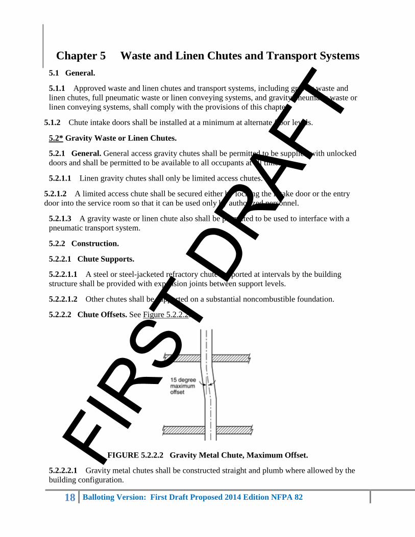
5.2.2.2 Chute Offsets. See Figure 5.2.2.2.
FIGURE 5.2.2.2 Gravity Metal Chute, Maximum Offset.
5.2.2.2.1 Gravity metal chutes shall be constructed straight and plumb where allowed by the
building configuration.
FIRS
T DR
AFT

19 Balloting Version: First Draft Proposed 2014 Edition NFPA 82
5.2.2.2.2 Gravity metal chutes shall be permitted to be offset a maximum of 15 degrees from
plumb with the approval of the authority having jurisdiction.
5.2.2.2.3 Offsets shall be limited to a maximum of one offset for every two floors.
5.2.2.2.4 A single offset shall be completed (returned to vertical) between floors.
5.2.2.2.5 No access door shall be less than 1.2 m (4 ft) above an offset.
5.2.2.2.6 The portion of chute between the highest intake door and the chute termination shall be
permitted to be offset a maximum of 45 degrees from the plumb, subject to the approval of the
authority having jurisdiction.
5.2.2.2.7 For the purpose of this standard, a single chute offset from vertical shall include a
return of the chute to vertical.
5.2.2.3 Standard Dimensions of Waste and Linen Gravity Chutes. Standard gravity chutes
shall be a minimum of 571 mm (22½ in.) by 571 mm (22½ in.) or 610 mm (24 in.) in diameter.
5.2.2.4 Chute Venting.
5.2.2.4.1 A waste or linen chute shall extend (full size) at least 0.92 m (3 ft) above the roof of a
building of Type II-000, Type III, Type IV, or Type V construction. (See NFPA 5000, Building
Construction and Safety Code.)
5.2.2.4.2 The chute shall be permitted to extend less than 0.92 m (3 ft) above the roof of a
building of Type I, Type II-222, or Type II-111 construction subject to the approval of the
authority having jurisdiction. (See NFPA 5000.)
5.2.2.4.3 The chute shall be open to the atmosphere, with the opening being the same cross-
sectional area as the chute.
5.2.2.4.4 The portion of chute between the highest intake door and the top of the chute vent shall
be permitted to be offset a maximum of 45 degrees from the plumb, subject to the approval of the
authority having jurisdiction.
5.2.2.5 Masonry Waste Chutes.
5.2.2.5.1 Masonry waste chutes shall be constructed of clay or shale brickwork not less than
203 mm (8 in.) thick or of reinforced concrete not less than 152 mm (6 in.) thick. Such chutes
shall be lined with low-duty refractory brick (as defined in ASTM C 27) not less than 114 mm
(4½ in.) thick.
5.2.2.5.2 Equivalent construction with walls providing a 2 hour fire resistance rating with
equivalent structural features shall be acceptable.
5.2.2.5.3 Lined masonry chutes that comply with 5.2.2.5 shall not require automatic sprinkler
protection.
5.2.2.6 Lined Metal Waste Chutes. FIRS
T DR
AFT

20 Balloting Version: First Draft Proposed 2014 Edition NFPA 82
5.2.2.6.1 Metal waste chutes shall be permitted to be lined with low-duty refractory brick (as
defined in ASTM C 27) not less than 63.5 mm (2½ in.) thick or equivalent castable refractories.
5.2.2.6.2 Lined metal chutes that comply with 5.2.2.6.1 shall not require automatic sprinkler
protection.
5.2.2.6.3 All unlined steel chutes shall be protected internally by automatic sprinklers. (See
5.2.3.3.1.)
5.2.2.7 Metal Chute Wall Thickness.
5.2.2.7.1 Metal waste or linen chutes shall be made of stainless steel, galvanized steel, or
aluminum-coated steel with no screws, rivets, or other projections on the interior surface of the
chute.
5.2.2.7.2 Laps or joints shall be designed so that liquid will drain to the interior of the chute.
5.2.2.7.3 The steel shall not be lighter than 16 U.S. gauge.
5.2.2.7.4 Special waste chutes designed to handle dense or heavy material over 1500 kg/m3 (10
lb/ft3) shall be made of steel not lighter than 14 U.S. gauge.
5.2.2.8 Medium-Heat Chimneys.
5.2.2.8.1 Listed medium-heat appliance chimney sections shall be acceptable for use as trash
chutes.
5.2.2.8.2 Listed medium-heat chimney shall not require automatic sprinkler protection.
First Revision No. 11:NFPA 82-2009 [FR 9: FileMaker]
5.2.3 Chute Enclosure (Chase). 5.2.3.1 General. 5.2.3.1.1 Vertical waste or linen chutes enclosures in all stories above the storage or compacting room shall be enclosed within a continuous fire-rated constructed of materials enclosure consistent with the building construction type. 5.2.3.1.2 The walls of the enclosure shall be continuous and have a fire resistance rating of not less than 2 hours for chutes connecting if the building is four or more stories in height and not less than 1 hour for chutes connecting if the building is less than four stories in height. 5.2.3.1.3 Openings in the fire resistance-–rated enclosure shall be have a fire protection rating as follows: (1) 1½1/2-hour fire resistance protection rating for 2-hour fire resistance-–rated enclosures (2) 1-hour fire resistance protection rating for 1-hour fire resistance-–rated enclosures 5.2.3.2 Chute Discharge Doors. 5.2.3.2.1*The bottom of a waste chute shall be protected by an approved automatic closing or self-closing door or fire damper of construction that resists fire in accordance with 5.2.3.1 is equivalent to the opening fire protection rating of the chute in 5.2.3.1.3. 5.2.3.2.2 The waste chute discharge door shall not be required to have a positive latch. FI
RST
DRAF
T

21 Balloting Version: First Draft Proposed 2014 Edition NFPA 82
5.2.3.2.23 The bottom of a linen chute shall be protected by a listed automatic closing or self-closing fire door or fire dampers that provides a fire protection rating in accordance with 5.2.3.1.3. 5.2.3.2.34 Chute discharge doors or fire dampers shall be permitted to be held open by a fusible link. 5.2.3.2.3 Chute discharge doors shall be permitted to be held open by a fusible link.
First Revision No. 11:NFPA 82-2009 [FR 10: FileMaker]
5.2.3.3 Chute Intake Doors. 5.2.3.3.1 General Access Gravity Waste Chutes. 5.2.3.3.1.1 All chute intake doors into a waste chute shall be provided with a self-closing, positive latching frame and gasketed fire door assembly in accordance with 5.2.3.1.3. having a fire protection rating of not less than 1 hour. 5.2.3.3.1.2 The fire door assembly frame shall be installed in accordance with their its listing. fastened into the chute and the shaft wall. 5.2.3.3.1.3 The design and installation shall be such that no part of the frame or door projects into the chute. 5.2.3.3.1.4 The area of each chute intake door shall be limited to one-third of the cross-sectional area of a square chute and 44 percent of the area of a round chute. 5.2.3.3.2 Limited-Access Gravity Chutes. 5.2.3.3.2.1 All chute intake doors into a linen or waste chute shall be provided with a self-closing, positive-latching frame and gasketed fire door assembly in accordance with 5.2.3.1.3. having a fire protection rating of not less than 1 hour. 5.2.3.3.2.2 The fire door assembly frame shall be installed be in accordance with their its listing. fastened into the chute and the shaft wall. 5.2.3.3.2.3 The design and installation shall be such that no part of the frame or door projects into the chute. 5.2.3.3.2.4 A key shall be required to open the door. 5.2.3.3.2.5 The area of each waste chute intake door shall be limited to two-thirds of the cross-sectional area of the chute. 5.2.3.3.2.6 The area of each linen chute intake door shall not exceed the cross-sectional area of the chute.
5.2.4 Chute Discharge Rooms.
5.2.4.1 General.
First Revision No. 18:NFPA 82-2009 [FR 24: FileMaker]
5.2.4.1.1 Waste and linen chutes shall terminate or discharge directly into a room having a minimum fire resistance rating not less than that specified for the chute enclosure. 5.2.4.1.2 Openings into such a chute discharge room or compartment shall be protected by an approved self-closing fire doors assembly having a minimum fire protection rating not less than that specified for the chute enclosure. FI
RST
DRAF
T
22 Balloting Version: First Draft Proposed 2014 Edition NFPA 82
5.2.4.1.3 Chute-to-Incinerator Interface. Trash gravity chutes shall not discharge directly into
an incinerator.
First Revision No. 17:NFPA 82-2009 [FR 11: FileMaker]
5.2.5 Service Opening Chute Intake Rooms. 5.2.5.1 General. 5.2.5.1.1 Every chute intake service opening shall be in a room or compartment that is separated from the other parts of the building by walls, partitions, floors, and floor-ceiling assemblies having a fire resistance rating of not less than the required rating of the chute enclosure as specified in 5.2.3.1. 5.2.5.1.32 Openings into such a chute intake room or compartment shall be protected by an approved automatic or self-closing fire doors assembly have a fire protection rating as follows: that are appropriate for protecting the openings or are of not less than a 1–hour partition rating with a ¾-hour fire-rated door. (1) A- 1½1/2-hour fire protection rating for 2-hour fire resistance– rated enclosures (2) A ¾3/4-hour fire protection rating for 1-hour fire resistance– rated enclosures 5.2.5.1.23 Where chute intake service opening rooms are protected by automatic sprinklers, the room shall be enclosed in a minimum of 1-hour fire resistance ratinged construction, and openings shall be protected with ¾-hour fire rated doors. 5.2.5.1.4 The size of the chute intake service opening room or compartment shall not be less than that required to maintain a minimum 152.4 mm (6 in.) clearance between the closed chute intake door opening and the closed service opening room door. 5.2.5.2 Service Opening Chute Intake Room Key. 5.2.5.2.1 If entrance to a limited-access service opening chute intake room is gained by key, the service opening chute intake door shall not require a key to be opened. 5.2.5.2.2 One opening or the other shall be keyed.
5.2.5.2.3 Keying shall be required only for limited-access installations.
First Revision No. 10:NFPA 82-2009 [FR 19: FileMaker]
5.2.6 Automatic Sprinklers. 5.2.6.1 Gravity Chute. 5.2.6.1.1 Gravity chutes shall be protected internally by automatic sprinklers, unless the chute is in accordance with 5.2.2.5 or 5.2.2.6. 5.2.6.1.2 This protection requires that a A sprinkler shall be installed at or above the top chute intake service opening of the chute. 5.2.6.1.3 This protection requires that a Automatic sprinklers installed in gravity chute intakes service openings shall be recessed out of the chute area through which the material travels. 5.2.6.1.4 In addition, a A sprinkler shall be installed within the chute at alternate floor levels in chutes connecting more than buildings over two stories in height, with a mandatory sprinkler located at the lowest chute intake level. 5.2.6.1.5 Sprinkler system installation shall comply with NFPA 13, Standard for the Installation of Sprinkler Systems.
FIRS
T DR
AFT

23 Balloting Version: First Draft Proposed 2014 Edition NFPA 82
First Revision No. 10:NFPA 82-2009 [FR 4: FileMaker]
5.2.6.2 Chute Discharge Room. 5.2.6.2.1 Automatic sprinklers shall be installed in chute terminal discharge rooms.
5.3* Full Pneumatic Waste and Linen Conveying Systems.
5.3.1 General. A full pneumatic waste or linen transport system consists of full vacuum
stations equipped with inner doors and a locked outer door, an air source at the top of the riser,
an air inlet control damper, flanged riser piping, transport piping, collectors (receivers), and a fan
and fan damper.
5.3.2 Construction.
5.3.2.1 General.
First Revision No. 41:NFPA 82-2009 [FR 3: FileMaker]
5.3.2.1.1 Full vacuum loading stations chute intake doors shall be a minimum of 508 mm (20 in.) in diameter, shall have an inner door that is under processor control, and shall not yield under system vacuum. 5.3.2.1.2 The outer (loading) chute intake door shall be provided with a gasketed, self-closing, positive-latching fire door and frame assembly with a fire protection rating of not less than 1 hour.
5.3.2.1.3 The door frame shall be fastened into the station and shall be flush with the rated
shaft wall.
5.3.2.1.4 Minimum outer door size shall be 457 mm (18 in.) and shall be side hinged. Full
vacuum stations shall be constructed from a minimum of 14 U.S. gauge stainless or galvanized
steel.
5.3.2.2 Multibag Loading of Waste or Linen Systems.
5.3.2.2.1 During the multibag loading procedure, both the outer and the inner doors shall be
permitted to be open.
5.3.2.2.2 Only one inner door shall be open at a time.
First Revision No. 19:NFPA 82-2009 [FR 3: FileMaker]
5.3.2.3 ServiceLoading Chute Intake Rooms. 5.3.2.3.1 Every loading station chute intake door shall be in a room or compartment that is separated from other parts of the building by walls, partitions, floors, and floor-ceiling assemblies having a fire resistance rating of not less than 1 hour.
First Revision No. 19:NFPA 82-2009 [FR 12: FileMaker]
5.3.2.3.2 FIRS
T DR
AFT

24 Balloting Version: First Draft Proposed 2014 Edition NFPA 82
Openings into such a room or compartment shall be protected by an approved self-closing fire doors assembly with a fire protection rating of not less than ¾3⁄4 hour.
5.3.2.4 Riser Pipe.
5.3.2.4.1 Full pneumatic riser pipe shall have a minimum diameter of 508 mm (20 in.) and
shall be constructed from 16 U.S. gauge (minimum) stainless steel or galvanized or aluminum
coated steel, with no screws, rivets, or other projections on the interior surface of the pipe.
5.3.2.4.2 To avoid vacuum leaks, riser pipe shall be flanged, gasketed, and bolted.
5.3.2.5 Air Source.
5.3.2.5.1 A full pneumatic system requires a full-diameter air source for conveying materials
on a moving air stream.
5.3.2.5.2 The air source shall be a roof vent and curb, an all-weather elbow, or a louver through
the side of the building.
5.3.2.6 Full Vacuum Station Supports.
5.3.2.6.1 Full vacuum stations shall be supported at each floor by mounting plates or a steel
channel that will bridge the shaft opening.
5.3.2.6.2 Stations shall be bolted to prevent movement under transport conditions.
5.3.2.6.3 On floors where no station is installed, the riser pipe shall be supported at each floor.
5.3.2.7 Riser Offsets. Full pneumatic risers shall be permitted to be offset to fit building design
requirements.
5.3.3 Riser Enclosure (Chase).
5.3.3.1 General.
5.3.3.1.1 Full pneumatic stations and vertical risers shall be mounted within a continuous
enclosure constructed of materials that are noncombustible and that extend from floor to floor.
5.3.3.1.2 The walls of the enclosure shall have a fire resistance rating of not less than 1 hour if
the building is less than four stories in height and not less than 2 hours if the building is four or
more stories in height. (See 5.3.2.7 for offsets in full pneumatic riser piping.)
First Revision No. 20:NFPA 82-2009 [FR 3: FileMaker]
5.3.3.2 Loading Chute Intake Doors 5.3.3.2.1 All full vacuum loading station outer chute intake doors shall be provided with a gasketed, self-closing, positive-latching fire door and frame assembly with a fire protection rating of not less than 1 hour.
5.3.3.2.2 The door frame shall be installed onto the station and shall be set flush to the shaft
wall. FIRS
T DR
AFT

25 Balloting Version: First Draft Proposed 2014 Edition NFPA 82
5.3.3.2.3 The width of the opening shall be permitted to be equivalent to the internal diameter
of the chute, and the height shall be a maximum of one and a half times the diameter.
5.3.3.2.4 Minimum door size for a waste or linen loading door shall be 457 mm (18 in.) and
shall be side-hinged.
5.3.4* Automatic Sprinklers Systems.
5.3.4.1 Full pneumatic-type risers shall be protected internally by automatic sprinklers.
First Revision No. 21:NFPA 82-2009 [FR 3: FileMaker]
5.3.4.2 A sprinkler shall be required at or above the top loading station chute intake door and at alternate floor levels in buildings over two stories in height, with a mandatory sprinkler located at the lowest loading station chute intake door.
5.3.4.3 Sprinklers shall be recessed out of the station area through which the material travels.
First Revision No. 22:NFPA 82-2009 [FR 25: FileMaker]
5.3.4.4 Sprinkler system installation shall comply with NFPA 13, Standard for the Installation of Sprinkler Systems.
5.3.5 Transport Piping.
5.3.5.1 Transport Piping Size and Thickness.
5.3.5.1.1 Transport piping shall have a minimum wall thickness of 16 U.S. gauge galvanized or
stainless steel and shall be sized to fit the system's needs.
5.3.5.1.2 Waste and linen transport systems shall be a minimum of 406 mm (16 in.) in
diameter.
5.3.5.1.3 Where all materials entering the pneumatic-powered system are processed through a
shredder, the transport pipe shall be permitted to be less than 406 mm (16 in.) in accordance with
the authority having jurisdiction.
5.3.5.2 Penetrating of Fire-Rated Assemblies.
5.3.5.2.1 Automatic fire dampers shall be installed at all points where the waste or linen
transport system penetrates fire-resistive partitions or floor assemblies. [See Figure 5.3.5.2.1(a)
through Figure 5.3.5.2.1(c).]
FIRS
T DR
AFT

26 Balloting Version: First Draft Proposed 2014 Edition NFPA 82
FIGURE 5.3.5.2.1(a) Full Pneumatic Riser with Offset.
FIGURE 5.3.5.2.1(b) Full Pneumatic System with Penetration of an Evacuation Corridor.
FIRS
T DR
AFT

27 Balloting Version: First Draft Proposed 2014 Edition NFPA 82
FIGURE 5.3.5.2.1(c) Full Pneumatic System with Penetration of a 2-Hour Fire-Rated
Wall.
5.3.5.2.2 The system shall shut down automatically upon the closing of one of the fire
dampers.
5.3.5.2.3* Fire dampers shall not be required where an engineered alternative system is provided
that is acceptable to the authority having jurisdiction.
5.3.5.3 Exiting from 2-Hour Fire-Rated Shafts.
5.3.5.3.1 Where the pneumatic transport pipe exits a 2-hour fire-rated shaft, the pipe wall
thickness shall be increased to 11 U.S. gauge from within the shaft to four pipe diameters beyond
the shaft wall.
5.3.5.3.2 The 11 U.S. gauge pipe shall be supported at 0.92 m (3 ft) intervals.
5.3.6 Collector Discharge Area.
First Revision No. 26:NFPA 82-2009 [FR 1: FileMaker]
5.3.6.1 The room or area where the collector discharges waste or linen shall be separated from the occupied part of the building by a 2-hour fire resistance-–rated wall.
5.3.6.2 The room or area shall be protected by a sprinkler system. Sprinkler system installation
shall comply with NFPA 13, Standard for the Installation of Sprinkler Systems.
5.4* Gravity Pneumatic Trash or Linen Conveying System.
5.4.1 General. A gravity pneumatic transport system shall comply with the requirements of
Section 5.4.
5.4.2 Construction.
5.4.2.1 General. All the requirements of Section 5.2 shall apply to gravity pneumatic
conveying systems.
5.4.2.2 Dampers.
5.4.2.2.1 Where an open funnel is employed as an interface between the gravity chute storage
section and the transport discharge damper, a normally closed, specially designed 11 U.S. gauge,
blade-type damper shall be installed at the bottom of the chute and above the funnel opening.
5.4.2.2.2 At the point of entry into the transport piping tee, a material discharge damper shall
be required to close off the transport piping when that riser is not being sequenced.
5.4.2.3 Chute Automatic Sprinklers. Where material is to be stored at the bottom of the chute
and above the riser discharge damper (above the transport tee), automatic sprinklers shall be
installed below the last service door on the chute.
5.4.2.4 Discharge Room Criteria. FIRS
T DR
AFT

28 Balloting Version: First Draft Proposed 2014 Edition NFPA 82
5.4.2.4.1 Where a gravity pneumatic system has any opening in the connection between the
chute and the transport pipe, the interface and the discharge damper shall be in a room that is
separated from other parts of the building by walls, partitions, and floor-ceiling assemblies
having a minimum fire resistance rating not less than that specified for the chute.
First Revision No. 25:NFPA 82-2009 [FR 1: FileMaker]
5.4.2.4.2 Openings to such rooms shall be protected by an approved automatic closing or self-closing fire door assembly having a fire protection rating of not less than 1½1⁄2-hours fire doors.
5.4.2.4.3 Automatic sprinklers shall be installed in chute discharge rooms.
5.4.3 Transport Piping.
5.4.3.1 Piping Size and Thickness.
5.4.3.1.1 Transport piping shall have a minimum wall thickness of 16 U.S. gauge galvanized or
stainless steel and shall be sized to fit the system's needs.
5.4.3.1.2 Waste and linen transport systems shall be a minimum of 406 mm (16 in.) in
diameter.
5.4.3.1.3 Where all materials entering the pneumatic-powered system are processed through a
shredder, the transport pipe shall be permitted to be less than 406 mm (16 in.) in accordance with
the authority having jurisdiction.
5.4.3.2 Penetrating of Fire-Rated Assemblies.
First Revision No. 24:NFPA 82-2009 [FR 1: FileMaker]
5.4.3.2.1 Automatic fire dampers shall be installed at all points where the waste or linen transport system penetrates fire resistance- –resistive rated partitions or floor assemblies.
5.4.3.2.2 The system shall shut down automatically upon the closing of one of the fire
dampers.
5.4.3.3 Exiting from 2-Hour Fire-Rated Shafts.
5.4.3.3.1 Where the pneumatic transport pipe exits a 2-hour fire-rated shaft, the pipe wall
thickness shall be increased to 11 U.S. gauge from within the shaft to four pipe diameters beyond
the shaft wall.
5.4.3.3.2 The 11 U.S. gauge pipe shall be supported at 0.92 m (3 ft) intervals.
5.4.4 Gravity Pneumatic Collector Discharge Area.
First Revision No. 23:NFPA 82-2009 [FR 1: FileMaker]
5.4.4.1 The room or area where the collector discharges waste or linen shall be separated from the occupied part of the building by a 2-hour fire resistance-–rated wall.
FIRS
T DR
AFT

29 Balloting Version: First Draft Proposed 2014 Edition NFPA 82
5.4.4.2 Where the room or area of collector discharge is within or abutting an occupied
building, the room or area shall be protected by a sprinkler system.
5.4.4.3 Sprinkler system installation shall comply with NFPA 13, Standard for the Installation
of Sprinkler Systems.
Chapter 6 Other Waste Handling Systems
6.1 General.
Waste handling systems and equipment, other than chute systems covered in Chapter 5,
including, but not limited to, waste cart transport systems, skip hoists, cranes and grapples, and
various types of conveyors, such as belt conveyors, pan conveyors, screw conveyors, vibratory
conveyors, and drag conveyors, shall comply with this chapter.
6.2 Waste Spillage Control.
Waste handling systems and equipment shall be designed and constructed to prevent or minimize
waste spillage so as to prevent potential fire problems.
6.3 Enclosure Requirements.
6.3.1 The building, rooms, or enclosures in which waste handling systems and equipment are
located and used for either interim storage of waste materials or the direct movement of waste
from storage areas to processing equipment, such as incinerators, or both, shall be shut off from
other areas of the building by walls, floor, and ceiling assemblies having a fire resistance rating
of not less than 2 hours.
First Revision No. 35:NFPA 82-2009 [FR 26: FileMaker]
6.3.2 6.3.2 Openings to such rooms shall be protected by an approved automatic closing or self-closing fire doors assembly with a fire protection rating of not less than 1 ½1⁄2 hours.
6.4 Automatic Sprinklers.
6.4.1 Automatic sprinklers shall be installed in rooms where waste handling systems and
equipment are used to transport waste from interim storage areas to waste processing equipment,
such as incinerators.
6.4.2 In locations or rooms where waste handling systems and equipment are used for interim
storage of waste only, the rooms shall be sprinklered in accordance with requirements specified
in Chapter 7.
Chapter 7 Waste Compactors
7.1 General.
FIRS
T DR
AFT

30 Balloting Version: First Draft Proposed 2014 Edition NFPA 82
Compactors shall be regulated by the provisions of this chapter.
7.2 Automatic Sprinklers.
7.2.1 All chute-fed compactors shall have an automatic sprinkler with a minimum 13 mm (½
in.) orifice installed in the hopper of the compactor.
7.2.1.1 Sprinklers shall be ordinary temperature-rated sprinklers.
7.2.1.2 Sprinklers shall be supplied by a minimum 25.4 mm (1 in.) ferrous piping or 19 mm (¾
in.) copper tubing line from the domestic cold water supply or by the building fire sprinkler
system.
7.2.1.3 Sprinkler water piping shall be protected from freezing in outdoor installations.
7.2.2 Hand-fed compactors located within a building and not operated in conjunction with a
chute shall not require installation of an automatic sprinkler in the hopper.
7.2.2.1 Compactors with charging capacities greater than 0.76 m3 (1 yd3) shall be enclosed in a
fire-rated room in conformance with 7.2.4.
7.2.3 Self-contained and breakaway compactors shall have an access door to the containers that
can be opened without disconnecting the containers from the compactor or shall be provided
with one 63.5 mm (2½ in.) hose connection that fits standard fire-fighting equipment near the top
of the container.
7.2.4 Chute terminal, compacting, or storage rooms shall be separated from other parts of the
building by walls, partitions, floor, and floor-ceiling assemblies having a fire resistance rating of
not less than 2 hours.
7.2.4.1 Openings to such rooms shall be protected by approved automatic-closing or self-
closing fire doors with a fire protection rating of not less than 1½ hours.
First Revision No. 36:NFPA 82-2009 [FR 21: FileMaker]
7.3 External Waste Compactors. (Reserved)
Chapter 8 Waste and Recyclables Storage Rooms
8.1* General.
Storage of waste and recyclables with a combined total volume exceeding 0.76 m3 (1 yd3) of
uncompacted measure of waste and recyclables shall be stored in a waste and recyclables storage
room complying with this chapter.
8.2 Fire Separation.
8.2.1 Waste and recyclables storage rooms shall be separated from other parts of the building by
walls and floor-ceiling assemblies having a fire resistance rating of not less than 1 hour.
First Revision No. 37:NFPA 82-2009
FIRS
T DR
AFT

31 Balloting Version: First Draft Proposed 2014 Edition NFPA 82
[FR 27: FileMaker] 8.2.2 Openings to such rooms shall be protected by an approved automatic closing or self-closing fire doors assembly with a fire protection rating of not less than ¾3⁄4 hour.
8.3 Automatic Sprinklers.
Waste and recyclables storage rooms shall be provided with automatic sprinklers installed in
accordance with NFPA 13, Standard for the Installation of Sprinkler Systems.
Chapter 9 Other Waste Processing Equipment
First Revision No. 15:NFPA 82-2009 [FR 13: FileMaker]
9.1* General. Other waste processing equipment shall include such devices as shredders, granulators, grinders, pulpers, and chippers.
9.2 Fire Separation.
9.2.1 Rooms in which waste processing systems and equipment are located shall be separated
from other parts of the building by walls, floor, and ceiling assemblies having a fire resistance
rating of not less than 2 hours.
First Revision No. 38:NFPA 82-2009 [FR 28: FileMaker]
9.2.2 Openings to such rooms shall be protected by an automatic closing or self-closing fire doors assembly with a fire protection rating of not less than 1½1⁄2 hours.
9.3 Explosion Protection. Devices that granulate waste materials and that produce potentially
explosive aerosols or combustible air mixtures shall be equipped with explosion protection
devices or systems.
9.4 Automatic Sprinklers.
9.4.1 Rooms in which waste processing equipment is located shall be installed with automatic
sprinklers.
9.4.2 Sprinkler system installation shall be in accordance with NFPA 13, Standard for the
Installation of Sprinkler Systems.
Chapter 10 Maintenance of Incinerators and Waste and Linen
Handling Systems and Equipment
10.1 Incinerators.
10.1.1 Incinerators shall be inspected and maintained not less than annually in accordance with
manufacturers' instructions.
FIRS
T DR
AFT

32 Balloting Version: First Draft Proposed 2014 Edition NFPA 82
10.1.2 A written record of the inspection shall be signed and retained for inspection by the AHJ.
10.2 Waste and Linen Chutes and Transport Systems.
10.2.1 Chute loading and discharge doors shall be maintained clear and unobstructed at all
times.
First Revision No. 27:NFPA 82-2009 [FR 14: FileMaker]
10.2.2 Waste and linen chutes and transport systems, including chute loading intake and discharge doors, shall be inspected and maintained not less than annually in accordance with manufacturers’ instructions.
10.2.2.1 If the waste and linen chute discharge door is equipped with a fusible link, the
following shall be conducted:
(1) Inspect the link to ensure it is not painted or coated with dust or grease.
(2) Evaluate the condition of chains/cables, s-hooks, eyes, and other devices that operate as a
result of the link melting to verify working condition (i.e., no kinked or pinched cable, no
twisted or inflexible chain).
(3) Remove the link for testing every 4 years to ensure full closure and positive latching.
(4) Reinstall the link after testing is complete.
(5) Replace the link if damaged or painted with a link of the same size, temperature, and load
rating.
10.2.3 A written record of the inspection shall be signed and kept for inspection by the AHJ.
10.3 Waste Compactors.
10.3.1 Waste compactors shall be inspected and maintained not less than annually in accordance
with manufacturers' instructions.
10.3.2 A written record of the inspection shall be signed and kept for inspection by the AHJ.
10.4 Waste Processing Equipment.
10.4.1 Waste processing equipment shall be inspected and maintained not less than annually in
accordance with manufacturers' instructions.
10.4.2 A written record of the inspection shall be signed and kept for inspection by the AHJ.
Annex A Explanatory Material
Annex A is not a part of the requirements of this NFPA document but is included for
informational purposes only. This annex contains explanatory material, numbered to correspond
with the applicable text paragraphs.
FIRS
T DR
AFT

33 Balloting Version: First Draft Proposed 2014 Edition NFPA 82
A.1.3 It is recognized that there are many different incineration technologies and designs.
There also is wide variation in the types of waste that can be incinerated, including solids,
liquids, sludges, and fumes. This standard is not intended to cover or include all the design and
construction details for each incineration technology and application. However, all design,
construction, control, and other features needed to reduce or minimize fire hazards shall be
required for all new incineration facilities to satisfy the authority having jurisdiction.
It is recognized that many different types of systems, equipment, and components are utilized for
handling or transporting waste. This standard is not intended to cover or include all the design
and construction details for each waste handling system and application. However, all design,
construction, control, and other features needed to reduce or minimize fire hazards shall be
required for such systems to satisfy the authority having jurisdiction and to comply with other
applicable standards.
A.3.2.1 Approved. The National Fire Protection Association does not approve, inspect, or
certify any installations, procedures, equipment, or materials; nor does it approve or evaluate
testing laboratories. In determining the acceptability of installations, procedures, equipment, or
materials, the authority having jurisdiction may base acceptance on compliance with NFPA or
other appropriate standards. In the absence of such standards, said authority may require
evidence of proper installation, procedure, or use. The authority having jurisdiction may also
refer to the listings or labeling practices of an organization that is concerned with product
evaluations and is thus in a position to determine compliance with appropriate standards for the
current production of listed items.
A.3.2.2 Authority Having Jurisdiction (AHJ). The phrase “authority having jurisdiction,” or
its acronym AHJ, is used in NFPA documents in a broad manner, since jurisdictions and
approval agencies vary, as do their responsibilities. Where public safety is primary, the authority
having jurisdiction may be a federal, state, local, or other regional department or individual such
as a fire chief; fire marshal; chief of a fire prevention bureau, labor department, or health
department; building official; electrical inspector; or others having statutory authority. For
insurance purposes, an insurance inspection department, rating bureau, or other insurance
company representative may be the authority having jurisdiction. In many circumstances, the
property owner or his or her designated agent assumes the role of the authority having
jurisdiction; at government installations, the commanding officer or departmental official may be
the authority having jurisdiction.
A.3.2.4 Listed. The means for identifying listed equipment may vary for each organization
concerned with product evaluation; some organizations do not recognize equipment as listed
unless it is also labeled. The authority having jurisdiction should utilize the system employed by
the listing organization to identify a listed product.
A.3.3.1.2 Gravity Waste or Linen Chute. A gravity chute also can be used to interface with a
pneumatic transport system. Access of chute intake doors might or might not be limited to the
use of keys.
A.3.3.7 Incinerator. The most applicable systems under this definition include, but are not
limited to, controlled air systems, rotary kiln systems, and multiple-chamber–type incineration
systems.
First Revision No. 4:NFPA 82-2009
FIRS
T DR
AFT

34 Balloting Version: First Draft Proposed 2014 Edition NFPA 82
[FR 18: FileMaker] A.3.3.9 Limited Combustible. See NFPA 259 and NFPA 220.
A.4.3 The changing composition of waste and regulations controlling temperatures and
emissions have created very aggressive flue gases. Refractories that were suitable in the past can
fail rapidly under existing conditions. There is no single material or family of materials suitable
for ensuring fire safety under all conditions; therefore, no specific materials are identified in this
annex. Critical temperatures, aggressive chemical components, and conditions creating
aggressive flue gases are identified. Selection of materials for chimney construction should be
based on those capable of withstanding these conditions.
Condensed Flue Acid Corrosives. Hydrochloric acid is formed when chloride-bearing materials
are oxidized. Hydrochloric acid is corrosive to all chimney linings and can destroy most metals
in concentrations as low as 26 ppm in flue gases. Acid concentration in flue gases ranges from 26
ppm to as high as 2095 ppm.
The acid dew point is about 62.7°C (145°F).
Sulfuric acid is formed when sulfur is oxidized to SO2, which is further oxidized to SO3, which
combines readily with water to form sulfuric acid, H2SO4. This flue acid is aggressive to most
chimney linings.
The acid dew point depends on the SO3 content of the flue gases. The maximum theoretical acid
dew point is about 204.4°C (400°F). Acid concentration can be as high as 80 percent but will
rapidly self-dilute to 35 percent.
Sulfurous acid is formed when SO2 combines with water. It condenses as sulfurous acid, H2SO3,
at the water dew point, or about 54.4°C (130°F), but it is not as aggressive as sulfuric or
hydrochloric acid and, therefore, does less damage.
Nitric acid is condensed in the water dew point area and also is not as aggressive to chimney
materials as other flue acids. It pacifies the surface of stainless steel, reducing the corrosive
effect of the other flue acids.
Miscellaneous Flue Acids. Other flue acids, formed by the halides, are very corrosive, but in
lesser amounts than chlorides. Hydrochloric acid is, therefore, the controlling acid.
Other flue acids that condense at the water dew point are present; however, hydrochloric and
sulfuric acids are the acids that cause the most corrosion in chimneys servicing incineration of
general waste.
Alkali Corrosives. Alkalis are formed by the oxidation of metal oxides that are found in paints,
ink, fillers, pigments, and so forth. The common alkalis are as follows:
(1) Soda (Na2O)
(2) Potash (K2O)
(3) Lithia (Li2O)
FIRS
T DR
AFT

35 Balloting Version: First Draft Proposed 2014 Edition NFPA 82
Increases in the quantities of plastics that are components of waste increase alkali in flue gases.
Alkalis form low-temperature melts that distress refractories, particularly those of low density.
Distress due to alkali attack can be observed as glazing or dripping of the refractory if the
temperature is high enough or, at lower temperatures, as a shelling or disintegration of the
surface.
Alkali disruption begins at about 871°C (1600°F) and increases as temperatures approach
1093°C (2000°F).
High-Temperature Acid Corrosives. Most common stainless steels show significant loss due to
chloride or other halogen vapors in flue gases when temperatures exceed 315°C (600°F).
Flue temperatures over 982°C (1800°F) encourage reaction of hydrochloric vapors with calcium
aluminate refractory binders. This reaction becomes more severe as temperatures approach and
exceed 1204°C (2200°F).
Free Chlorides and Alkalis. Where free chlorides are present with alkalis, these compounds can
condense within the lining, forming expansive alkali chloride phases. The presence of these
phases can result in cracking of the refractory.
Chimney Systems Below 93.3°C (200°F) Mid-Flue Temperature Downstream of Scrubber.
Chimney systems that allow flue surfaces to fall below 93.3°C (200°F) are subject to corrosion
by halogen acids, nitric acid, and others, with the prime corrosive acid being hydrochloric acid.
Metal Linings Assuming HCl Content to Be 26 ppm or Above in the Flue Gases. Most common
metals, such as Types 304, 304L, 316, and 316L stainless steels, and nickel-based alloys, such as
800, 600, 618, and 671, have shown significant corrosion when subjected to flue gases
containing 26 ppm hydrochloric acid and are not acceptable as flue liners.
Materials that exhibit essentially no corrosion attack when subjected to flue gases containing 26
ppm hydrochloric acid are as follows:
(1) Austenitic stainless steels: 904L, 254 SLX, 254 SMO, AL-6X, and 22-13-5
(2) Ferritic stainless steels: Ebrite 26-1, NuMonit, and 29-4C
(3) Nickel-based alloys: 690, 625, 825, and Hastelloys N, F, G, and C-276
This information was obtained from Technology Development for Corrosion Resistant
Condensing Heat Exchangers by Battelle, Columbus, OH.
First Revision No. 14:NFPA 82-2009 [FR 15: FileMaker]
Refractory and Other Linings. Refractory linings suitable for use downstream of scrubbers need to resist all of the condensed flue acids at low temperatures. The linings will become saturated and, therefore, need to resist stresses of expanding steam when temperatures elevate rapidly. They also need to resist thermal shock when heated refractory is suddenly exposed to water. Products suitable for this service should show evidence of no more than 3 percent weight loss when subjected to the acid resistance test in ASTM C 980, Standard
FIRS
T DR
AFT

36 Balloting Version: First Draft Proposed 2014 Edition NFPA 82
Specification for Industrial Chimney Lining Brick Acid Resistance Testing, in boiling hydrochloric and sulfuric acids.
Chimney Systems Below 315.8°C (600°F) Mid-Flue Temperature. Chimney systems that allow
flue surfaces in any portion of the system to fall below 315.8°C (600°F) can be subject to
corrosion by sulfuric acid. These temperatures usually are associated with waste heat recovery
boilers.
Lining suitable for this type of service should be dense, high in silica, and bonded with acid-
resistant binders (calcium aluminate binders cannot pass the acid-resistant test unless co-bonded
with potassium silicate). Material should withstand immersion in 5 percent sulfuric acid for 2000
hours at 21.1°C (70°F) with not more than 3 percent weight loss.
Chimney Systems 315.8°C to 815.6°C (600°F to 1500°F). These conditions existed prior to
current regulations for incineration. This temperature range avoids condensed flue acid and
problems with alkali. Refractories used in the past usually were lightweight with continuous
service temperatures of 982.2°C (1800°F) with excursions to 1093.3°C (2000°F).
Listed Medium-Heat Chimneys. Listed medium-heat appliance chimneys can be used and should
be installed in accordance with the conditions of the listing and the manufacturer's instructions.
Chimney Systems 815.6°C to 1204.4°C (1500°F to 2200°F). This temperature range requires
more Al2O3 and less SiO2 in the chemical composition. The material needs to meet the
temperature limitations of the specific incinerator involved. It is subject to attack by both alkali
and acid vapors, which become more severe as density is reduced; thus, high-density low-
porosity material should be used.
A.4.3.3.3.2 Equivalent thickness is that thickness capable of providing the same insulating and
structural values to limit skin temperatures to those temperatures specified in 4.2.2.5 under all
intended operating conditions.
A.4.3.3.4.3 Equivalent thickness is that thickness capable of providing the same insulating and
structural values to limit skin temperatures to those temperatures specified in 4.2.2.5 under all
intended operating conditions.
A.4.3.6 Such materials can include fiberglass reinforced plastic (FRP), refractories, and
mortars of special acid-resistant composition or specialized metals, such as Hastelloy or Inconel.
(See A.4.3 for further discussion.)
A.4.3.8.7 This requirement was initiated to avoid the serious corrosion problems inherent with
low-temperature incinerator flue gases. It also provides the high-temperature protection
necessary when the special equipment is bypassed for any purpose, including power failure. In
those cases where the bypass is such that the breaching also is bypassed, then the breaching need
not be high-temperature protected, but it should be protected by an acid-resistant coating suitable
for the operating conditions.
A.5.2 See Figure A.5.2(a) and Figure A.5.2(b) for examples of gravity chutes. FIRS
T DR
AFT

37 Balloting Version: First Draft Proposed 2014 Edition NFPA 82
FIGURE A.5.2(a) Gravity Linen Chute.
FIRS
T DR
AFT

38 Balloting Version: First Draft Proposed 2014 Edition NFPA 82
FIGURE A.5.2(b) Gravity Waste Chute.
First Revision No. 12:NFPA 82-2009 [FR 9: FileMaker]
A.5.2.3.2.1 The door or damper at the discharge opening of a waste chute is not required to be a labeled assembly; but rather shall be of construction similar to a rated assembly to afford the protection required by 5.2.3.1.3.
A.5.3 Figure A.5.3(a) is an example of a full pneumatic system, and Figure A.5.3(b) through
Figure A.5.3(e) are examples of engineered alternative systems.
FIRS
T DR
AFT

39 Balloting Version: First Draft Proposed 2014 Edition NFPA 82
FIGURE A.5.3(a) Full Pneumatic System.
FIRS
T DR
AFT

40 Balloting Version: First Draft Proposed 2014 Edition NFPA 82
FIGURE A.5.3(b) Fire Damper Engineering Alternative for Penetration of Floor at Base
of Shaft.
FIGURE A.5.3(c) Fire Damper Engineering Alternative for Penetration of Fire-Rated
Enclosure.
FIRS
T DR
AFT

41 Balloting Version: First Draft Proposed 2014 Edition NFPA 82
FIGURE A.5.3(d) Fire Damper Engineering Alternative for Penetration of Fire-Rated
Wall.
FIRS
T DR
AFT

42 Balloting Version: First Draft Proposed 2014 Edition NFPA 82
FIGURE A.5.3(e) Fire Damper Engineering Alternative for Penetration of Wall at Base of
Shaft.
A.5.3.4 See Figure A.5.3(a).
A.5.3.5.2.3 Examples of engineered alternative systems are shown in Figure A.5.3(b) through
Figure A.5.3(e). Other engineered alternative systems are acceptable if approved by the authority
having jurisdiction.
A.5.4 Figure A.5.4 is an example of various gravity pneumatic system arrangements.
FIGURE A.5.4 Gravity Pneumatic System.
A.8.1 One cubic yard is approximately equal to 220 gallons.
FIRS
T DR
AFT

43 Balloting Version: First Draft Proposed 2014 Edition NFPA 82
First Revision No. 15:NFPA 82-2009 [FR 13: FileMaker]
A.9.1 It is not the intent to consider portable shredders as waste processing equipment.
Annex B Informational References
B.1 Referenced Publications.
The documents or portions thereof listed in this annex are referenced within the informational
sections of this standard and are not part of the requirements of this document unless also listed
in Chapter 2 for other reasons.
B.1.1 NFPA Publications. National Fire Protection Association, 1 Batterymarch Park, Quincy,
MA 02169-7471.
NFPA 220, Standard on Types of Building Construction, 2001 edition.
NFPA 259, Standard Test Method for Potential Heat of Building Materials, 2001 edition.
B.1.2 Other Publications.
First Revision No. 28:NFPA 82-2009 [FR 6: FileMaker]
B.1.2.1 ASTM Publications. ASTM International, 100 Barr Harbor Drive, P.O. Box C700, West Conshohocken, PA 19428-2959. ASTM C 980, Acid Resistance Testing, 1995. Standard Specification for Industrial Chimney Lining Brick, 2010.
B.1.2.2
Technology Development for Corrosion Resistant Condensing Heat Exchangers, Battelle,
Columbus, OH.
B.2 Informational References.
(Reserved)
B.3 References for Extracts in Informational Sections. (Reserved)
FI
RST
DRAF
T