Embed Size (px)
Citation preview
Copyright ©2004 Virtusa Corporation | CONFIDENTIAL
Modeling Architecture
2Copyright ©2004 Virtusa Corporation | CONFIDENTIAL
What is an architecture model ?
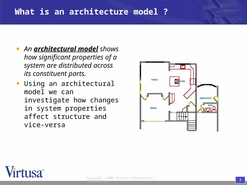
• An architectural model shows how significant properties of a system are distributed across its constituent parts.
• Using an architectural model we can investigate how changes in system properties affect structure and vice-versa
3Copyright ©2004 Virtusa Corporation | CONFIDENTIAL
Will the house extension work for us ?
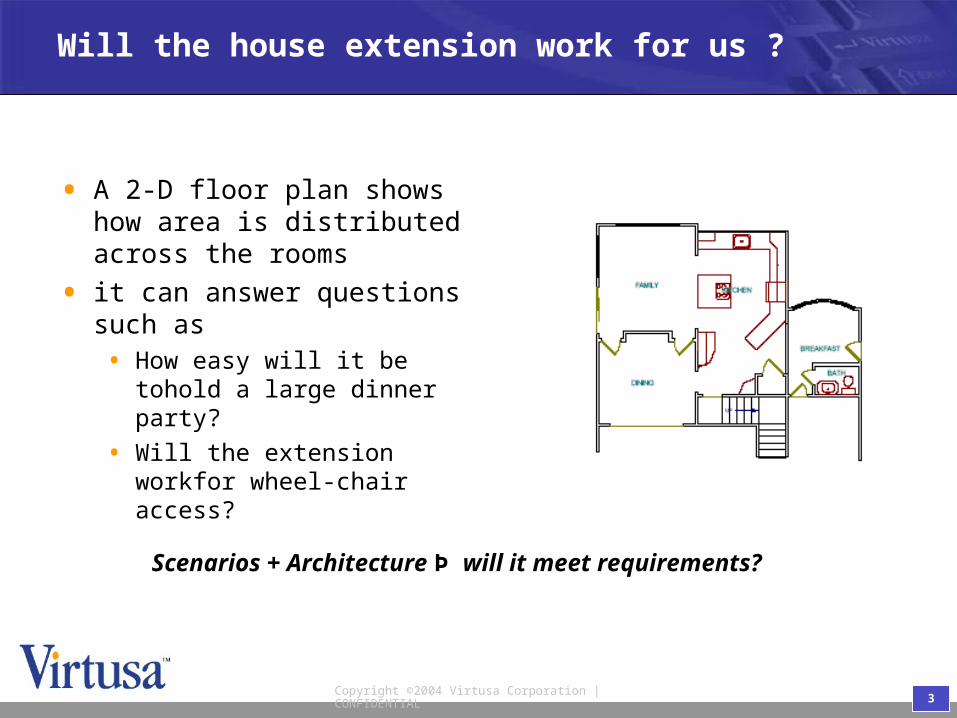
• A 2-D floor plan shows how area is distributed across the rooms
• it can answer questions such as• How easy will it be tohold a
large dinner party?
• Will the extension workfor wheel-chair access?
Scenarios + Architecture Þ will it meet requirements?

4Copyright ©2004 Virtusa Corporation | CONFIDENTIAL
Will the product be successful
• 3-d mockups define the basic topology of products
• they can answer questions such as • How easy is it to replace toner?
• Will copier fit through a doorway?
Scenarios + Architecture Þ will it meet requirements?
5Copyright ©2004 Virtusa Corporation | CONFIDENTIAL
Modeling architecture: Why ?
• Create Architecture Document• Common language
• Make knowledge commonly available
• Rationale of the current system• Explicit, Shared
• A tool for evaluating the impact of new requirements on the system
• Free architects from training to do their real job: design work
6Copyright ©2004 Virtusa Corporation | CONFIDENTIAL
When to model architecture ?
• While developing new system
• Changing system:• adapting existing architecture documentation
• recapture architecture prior to changes
• Special communication needs• common ground for discussion is missing
• integrating new people, experts leaving
• architects want to architect, not re-explain architecture

7Copyright ©2004 Virtusa Corporation | CONFIDENTIAL
Users of architecture
• Architecture fosters a shared understanding for communication, co-ordination, etc
• BUT different types of architecture

8Copyright ©2004 Virtusa Corporation | CONFIDENTIAL
Software Archtecture
• the structure … of a system, comprising
• software components,• their externally visible
• properties, and
• the inter-relationships
• components are large grained
Software Architecture in Practice, L. Bass, P. Clements and R.Kazman, Addison-Wesley, 1997.

9Copyright ©2004 Virtusa Corporation | CONFIDENTIAL
Elements of software architecture
InterfacesDynamic Behavior
Structure
Conceptual Framework
What the concepts areand what they mean.
Components& communicationpaths
How the componentsinteract and change state.
Servicesprovided &required bysystem

10Copyright ©2004 Virtusa Corporation | CONFIDENTIAL
Elements of software architecture
InterfacesDynamic Behavior
Structure
Conceptual Framework
Class Diagrams
Object Diagrams(Part of class
diagrams)
Collaboration Diagrams
Interface(part of class diagrams)

11Copyright ©2004 Virtusa Corporation | CONFIDENTIAL
UML and Development process
InterfacesDynamic Behavior
Structure
Conceptual Framework
Requirements(Focus: Exterior of system
Granularity: Actors/Systems)
Requirements(Focus: Exterior of system
Granularity: Actors/Systems)
Architecture(Focus: Interior of system, Exterior of components,
connectorsGranularity:
Components/Connectors)
Architecture(Focus: Interior of system, Exterior of components,
connectorsGranularity:
Components/Connectors)
Design(Focus: Interior of components,
connectorsGranularity: Objects)
Design(Focus: Interior of components,
connectorsGranularity: Objects)
Lexi
con
12Copyright ©2004 Virtusa Corporation | CONFIDENTIAL
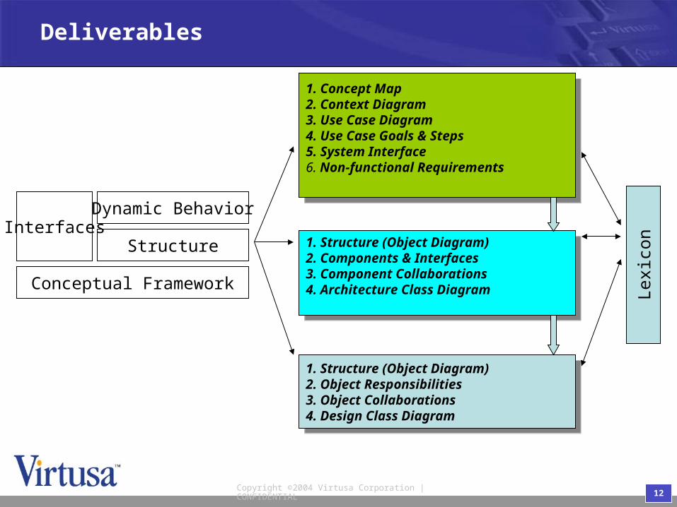
Deliverables
InterfacesDynamic Behavior
Structure
Conceptual Framework
1. Concept Map2. Context Diagram3. Use Case Diagram4. Use Case Goals & Steps5. System Interface6. Non-functional Requirements
1. Concept Map2. Context Diagram3. Use Case Diagram4. Use Case Goals & Steps5. System Interface6. Non-functional Requirements
1. Structure (Object Diagram)2. Components & Interfaces3. Component Collaborations4. Architecture Class Diagram
1. Structure (Object Diagram)2. Components & Interfaces3. Component Collaborations4. Architecture Class Diagram
1. Structure (Object Diagram)2. Object Responsibilities3. Object Collaborations4. Design Class Diagram
1. Structure (Object Diagram)2. Object Responsibilities3. Object Collaborations4. Design Class Diagram
Lexi
con
13Copyright ©2004 Virtusa Corporation | CONFIDENTIAL
Using UML in development
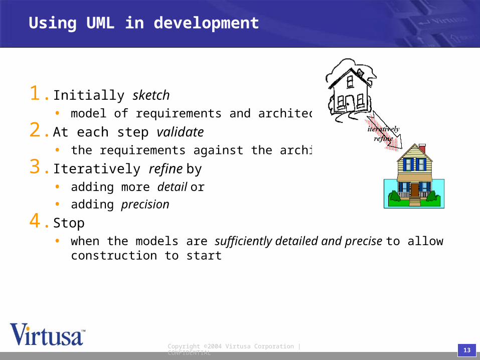
1.Initially sketch• model of requirements and architecture
2.At each step validate• the requirements against the architecture
3.Iteratively refine by• adding more detail or
• adding precision
4.Stop• when the models are sufficiently detailed and precise to allow
construction to start

14Copyright ©2004 Virtusa Corporation | CONFIDENTIAL
Conceptual Framework
Interfaces
Dynamic Behavior
Structure
Conceptual Framework
15Copyright ©2004 Virtusa Corporation | CONFIDENTIAL
Conceptual Framework
• At each stage during development it is necessary to define concepts that are used• requirements (concept map) - concepts needed to model
problem domain
• architecture (architecture class diagram) – classes needed for components & inter-component communication
• design (design class diagram) - as for architecture but with implementation details, e.g. operations, visibilities etc.
• UML class diagram notation allows concepts to be defined throughout the development process
16Copyright ©2004 Virtusa Corporation | CONFIDENTIAL
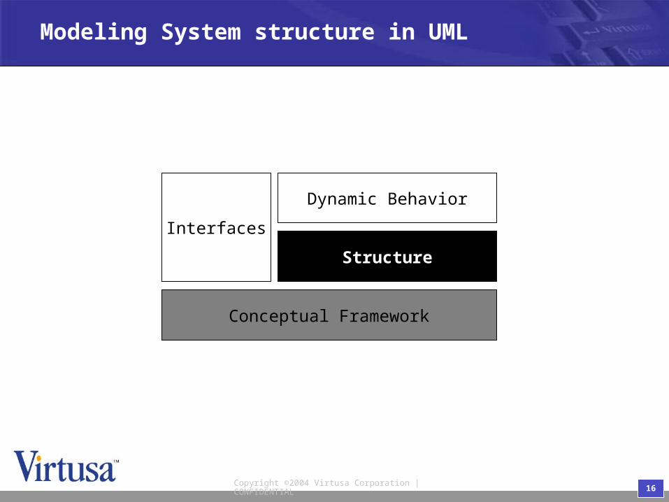
Modeling System structure in UML
Interfaces
Dynamic Behavior
Structure
Conceptual Framework

17Copyright ©2004 Virtusa Corporation | CONFIDENTIAL
Modeling System structure in UML
• The structure of a system can be modeled as a Class depicting the object and the component instances that it contains
• A Class Diagram which contains object instances is referred to as an Object Diagram
• Composite Aggregation models the notion of containment

18Copyright ©2004 Virtusa Corporation | CONFIDENTIAL
Requirements: Structure
• We model the structure during requirements by creating a context diagram, whose purpose is:• define the system boundary
• shows the actors and their interaction with the system.

19Copyright ©2004 Virtusa Corporation | CONFIDENTIAL
Architecture: Structure
• System is shown as a composite aggregation with components as objects inside the system object.
• For better visualization multi-objects are used.
• Use also navigability, multiplicity, association names, ...
20Copyright ©2004 Virtusa Corporation | CONFIDENTIAL
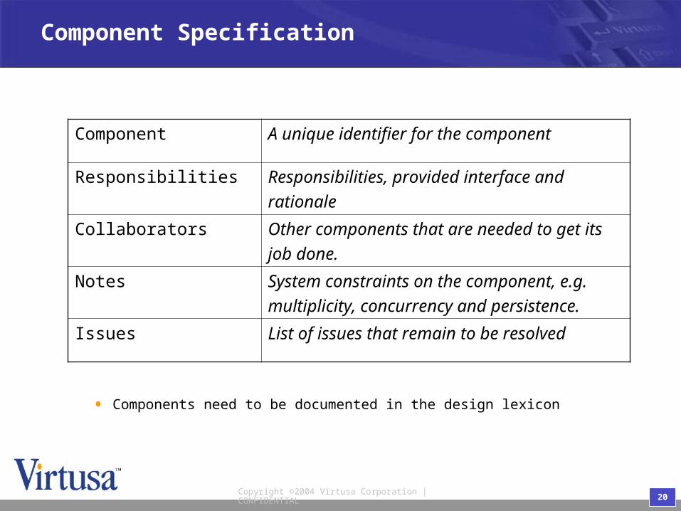
Component Specification
Component A unique identifier for the component
Responsibilities Responsibilities, provided interface andrationale
Collaborators Other components that are needed to get itsjob done.
Notes System constraints on the component, e.g.multiplicity, concurrency and persistence.
Issues List of issues that remain to be resolved
• Components need to be documented in the design lexicon

21Copyright ©2004 Virtusa Corporation | CONFIDENTIAL
Dynamic Behavior
Interfaces
Dynamic Behavior
Structure
Conceptual Framework
22Copyright ©2004 Virtusa Corporation | CONFIDENTIAL
Dynamic Behavior
• Dynamic Behavior: how entities interact to achieve some goal
• UML provides a number of notations:• sequence diagrams, collaboration diagrams, use cases, activity
diagrams
• The notations can be used to either• illustrate specific instances of interaction or
• define the generic (i.e algorithmic) pattern of interaction to achieve some result
23Copyright ©2004 Virtusa Corporation | CONFIDENTIAL
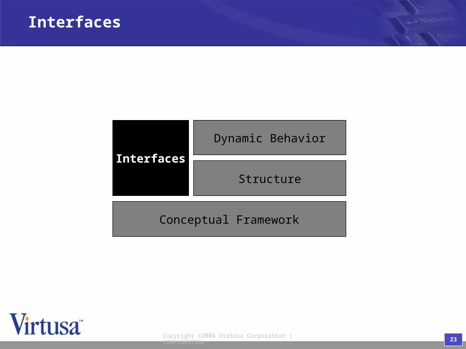
Interfaces
Interfaces
Dynamic Behavior
Structure
Conceptual Framework

24Copyright ©2004 Virtusa Corporation | CONFIDENTIAL
Interface
• An interface is a set of operations defining a coherent set of services offered by an instance
• Interfaces separate the services provided by a system from their implementation
• Interfaces are essential for plug & play of components
• UML Interfaces provide a syntactic specification

25Copyright ©2004 Virtusa Corporation | CONFIDENTIAL
Document Interfaces
Aspects Meaning How modeled
Syntax signature of eachoperation
•<<Interface>> stereotype on UML Class Diagram
Semantic meaning of eachoperation
•Limited modeling using notes and constraints on UML Class Diagram
Protocol dependencies betweenthe order of Invocations
•Pre- & post-condition Constraints
•UML Statecharts
Dependencies Which classes provideand which require agiven interface
•depends on and realizes relationships UML Class Diagram

26Copyright ©2004 Virtusa Corporation | CONFIDENTIAL
Interface semantics
• UML interfaces are syntactic - semantics can be captured by constraints
• Two aspects of semantics:1. The semantics of each operation can be defined
• informally or by pre- & postconditions .2. The permissible ordering of messages (i.e. protocol) can be
defined by• statecharts or collaboration diagrams.

27Copyright ©2004 Virtusa Corporation | CONFIDENTIAL
Interface protocol specification
• A protocol constrains the order in which the interface operations may be invoked.
• A protocol is sometimes referred to as the "object lifecycle".
• Statecharts are excellent for specifying protocols of interfaces, classes or objects
• A statechart models behavior in terms of the sequence of states an object that satisfies interface goes through in response to events

28Copyright ©2004 Virtusa Corporation | CONFIDENTIAL
Interface Specification
• Syntactic specifications are essential for distributed systems
• Complete semantic interface specifications are expensive to develop - use only where justified by technical or business risk
• Statecharts are excellent for specifying protocols
• Pre- and post conditions are excellent for specifying individual operations but expensive when very precise (i.e. formal).
29Copyright ©2004 Virtusa Corporation | CONFIDENTIAL
What is missing in UML for Architecture modeling ?

30Copyright ©2004 Virtusa Corporation | CONFIDENTIAL
Non-functional Requirements
• Requirements other than computing correct results• constraints and qualities.
• Constraints apply to the system as a whole• e.g time-to-market or the need for interoperability with legacy
systems.
• Qualities include• usability, extensibility and configurability.
• QoS attributes, e.g. performance, reliability etc.,
• UML does NOT provide notation

31Copyright ©2004 Virtusa Corporation | CONFIDENTIAL
Non-functional requirements: System Scale
• The scale of a system is the amount simultaneous concurrency and distribution system must support
• Depends on• How many actor instances are present in environment
• How many use case instances can be active simultaneously?
• Priority ordering between simultaneous use case instances
• Geographical distribution of actors
• Scale is a key non-functional requirement that architecture must satisfy
32Copyright ©2004 Virtusa Corporation | CONFIDENTIAL
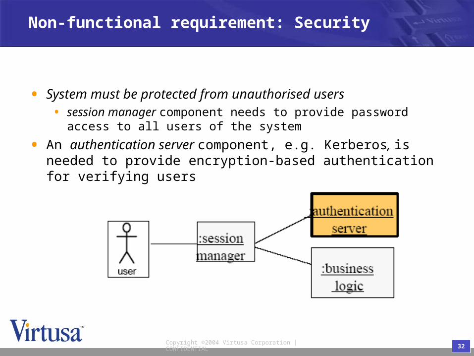
Non-functional requirement: Security
• System must be protected from unauthorised users• session manager component needs to provide password
access to all users of the system
• An authentication server component, e.g. Kerberos, is needed to provide encryption-based authentication for verifying users

33Copyright ©2004 Virtusa Corporation | CONFIDENTIAL
Non-functional requirement: fault tolerant
• System must be able to mask a crash of any one component
• e.g database controller is a single point of failure; replication should be used to mask failure.
34Copyright ©2004 Virtusa Corporation | CONFIDENTIAL
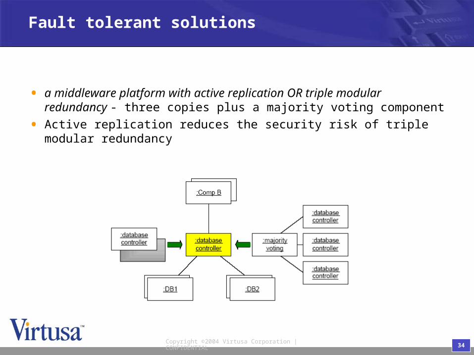
Fault tolerant solutions
• a middleware platform with active replication OR triple modular redundancy - three copies plus a majority voting component
• Active replication reduces the security risk of triple modular redundancy

35Copyright ©2004 Virtusa Corporation | CONFIDENTIAL
Example: FT CORBA
• CORBA's inherent benefits, such as • location transparency,
• platform portability,
• network transparency,
• and language independenceare important factors in its wide-ranging success.
• CORBA-based middleware often cannot meet the demanding QoS needs of certain specialized applications
• Real-time (RT) CORBA and Fault Tolerant (FT) CORBA are the new solutions.

36Copyright ©2004 Virtusa Corporation | CONFIDENTIAL
…Example: FT CORBA
• infrastructure should be characterized by • redundancy,
• fault detection,
• and fault recovery.
• A replicated object is realized as a group of CORBA objects each having the same interface.
• Each member of an object group, referred to as a replica, has a unique IOR.
37Copyright ©2004 Virtusa Corporation | CONFIDENTIAL
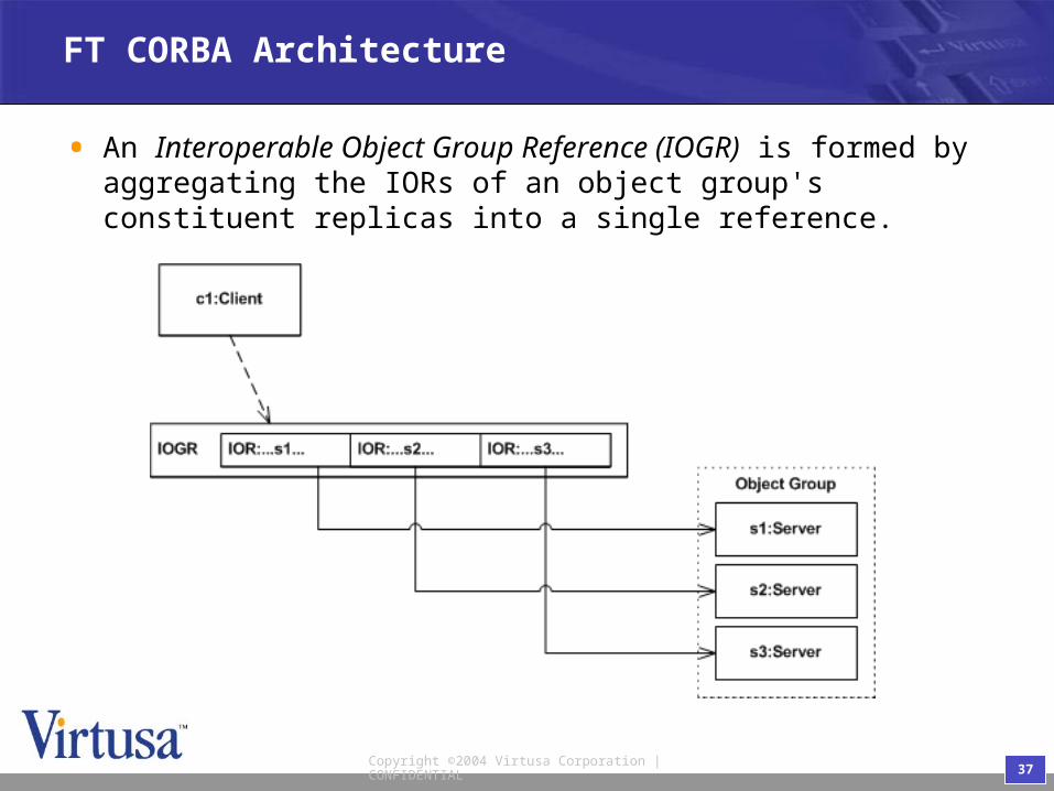
FT CORBA Architecture
• An Interoperable Object Group Reference (IOGR) is formed by aggregating the IORs of an object group's constituent replicas into a single reference.

38Copyright ©2004 Virtusa Corporation | CONFIDENTIAL
FT CORBA Architecture: Replications
• FT CORBA defines various replication styles that fall into essentially three categories: • stateless,
• passive,
• and active.

39Copyright ©2004 Virtusa Corporation | CONFIDENTIAL
FT CORBA Architecture: Stateless replication
• stateless • don't maintain context information between invocations.
• Stateless replicas remain consistent with one another since they have no persistent context. Thus, no mechanisms are required to keep the replicas consistent

40Copyright ©2004 Virtusa Corporation | CONFIDENTIAL
FT CORBA Architecture: Passive replication
• passive replication • maintain at least some context information between
invocations.
• designates a single replica as the primary and all other replicas as backups.
• checkpoint logging and recovery mechanism.

41Copyright ©2004 Virtusa Corporation | CONFIDENTIAL
FT CORBA Architecture: Active replication
• active replication • maintain context information between invocations.
• An object group that employs an active replication style doesn't distinguish between primary and backup replicas.
• All requests are processed by all replicas.

42Copyright ©2004 Virtusa Corporation | CONFIDENTIAL
Impact of non-functional requirements
• Architecture structure based on functionality• style
• architectural behavior (use cases etc)
• Architecture must also satisfy non-functional requirements• may determine selection of a particular style
• may add or modify components or interfaces

43Copyright ©2004 Virtusa Corporation | CONFIDENTIAL
USA UK INDIA SRI LANKA