Embed Size (px)
Citation preview

8/7/2019 Copy of CHAP11_rev
http://slidepdf.com/reader/full/copy-of-chap11rev 1/34
Cordless Systems andWireless Local Loop (WLL)
Chapter 11
8/7/2019 Copy of CHAP11_rev
http://slidepdf.com/reader/full/copy-of-chap11rev 2/34
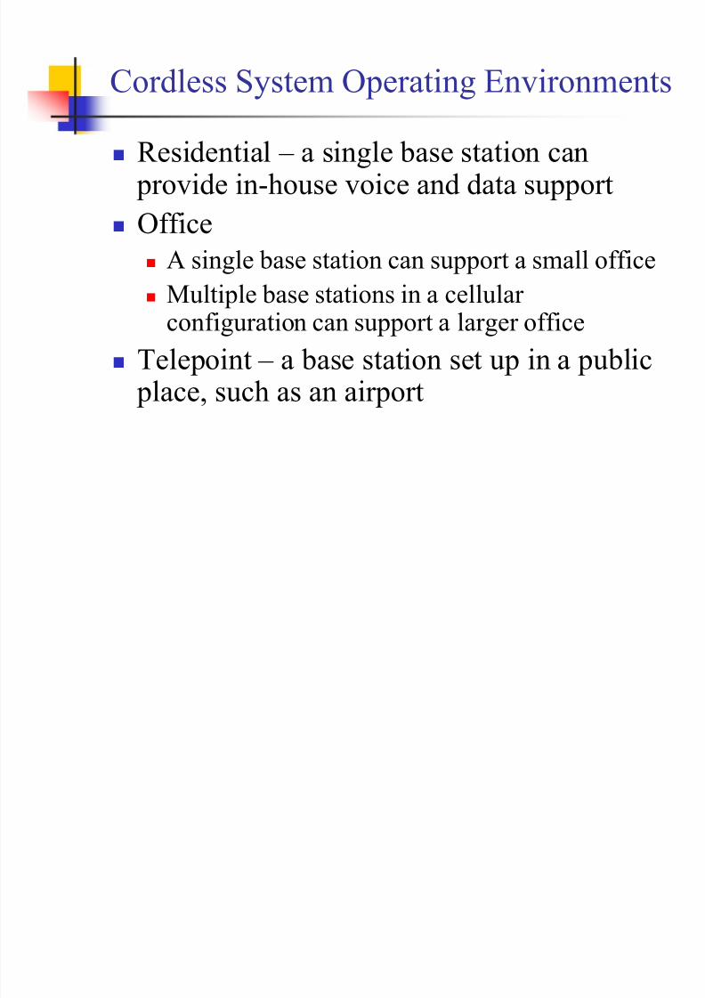
Cordless System Operating Environments
Residential ± a single base station can provide in-house voice and data supportOffice
A single base station can support a small officeMultiple base stations in a cellular configuration can support a larger office
Telepoint ± a base station set up in a public place, such as an airport
8/7/2019 Copy of CHAP11_rev
http://slidepdf.com/reader/full/copy-of-chap11rev 3/34
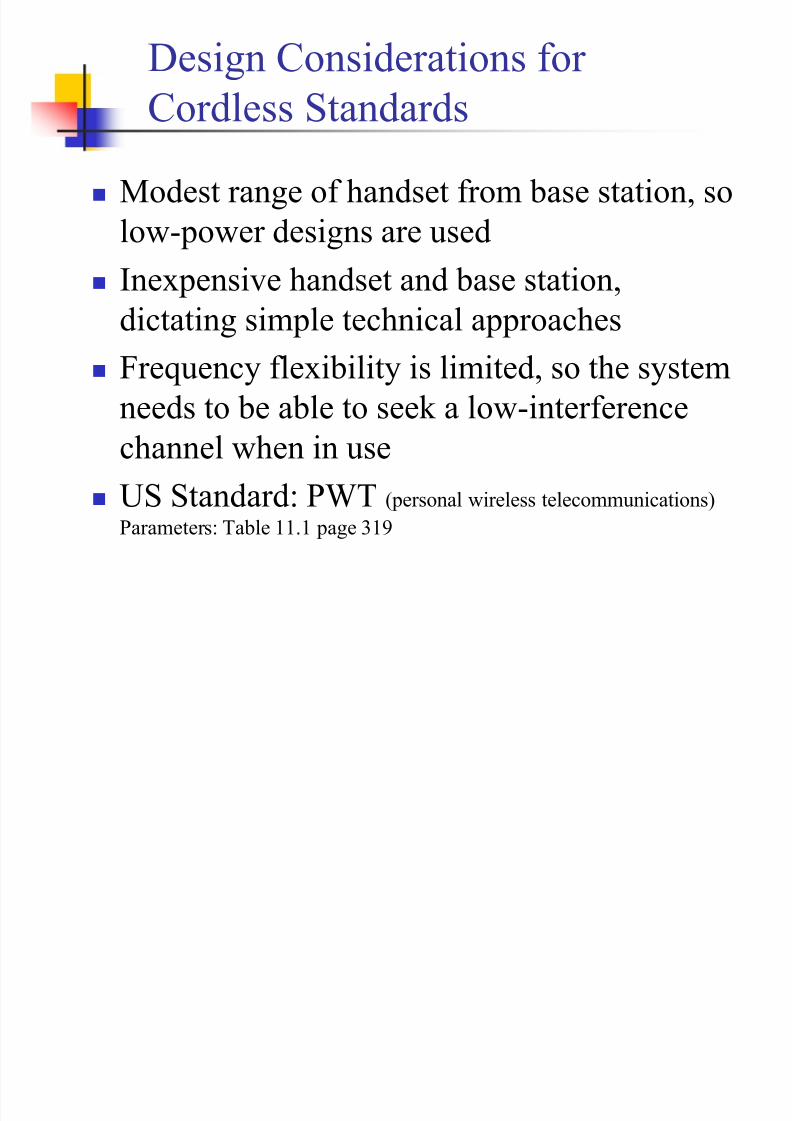
D esign Considerations for Cordless Standards
Modest range of handset from base station, solow-power designs are used
Inexpensive handset and base station,dictating simple technical approachesFrequency flexibility is limited, so the system
needs to be able to seek a low-interferencechannel when in useUS Standard: PWT (personal wireless telecommunications)Parameters: Table 11.1 page 319

8/7/2019 Copy of CHAP11_rev
http://slidepdf.com/reader/full/copy-of-chap11rev 4/34
Time D ivision D uplex (T DD )
TDD also known as time-compressionmultiplexing (TCM)D
ata transmitted one direction at a time,with transmissions going both directionsSimple T DD
TD MA T DD

8/7/2019 Copy of CHAP11_rev
http://slidepdf.com/reader/full/copy-of-chap11rev 5/34
Simple T DD
B it stream is divided into equal segments, compressed intime to a higher transmission rate and transmitted in bursts
Each side must alternate transmissions thus the data rate at
which blocks can be transmitted by EITHER side is1/2( T p+ T b+ T g )
For one side, the effective bits transmitted per second: R = B/2(T p+ T b+ T g )
R = effective data rateB = block size in bitsT p = propagation delayT b = burst transmission timeT g
= guard time (allow channel to settle down)

8/7/2019 Copy of CHAP11_rev
http://slidepdf.com/reader/full/copy-of-chap11rev 6/34
Transmission Using TDD

8/7/2019 Copy of CHAP11_rev
http://slidepdf.com/reader/full/copy-of-chap11rev 7/34
Simple T DD
Actual data rate of the medium, A : A = B /T b (block size in bits / time to transmit block)
Combined with previous equation:
Thus the actual data rate on the link is more thandouble the effective data rate seen by either of thetwo sidesB lock Size: as B increased, actual data rate Adecreases but signal delay increases due to
buffering which is bad for voice traffic
¹¹ º ¸
©©ª¨!
b
g p
T T T
R A 12

8/7/2019 Copy of CHAP11_rev
http://slidepdf.com/reader/full/copy-of-chap11rev 8/34
TD MA T DD
Wireless T DD typically used with T D MAA number of users receive forward channelsignals in turn and then transmit reversechannel signals in turn, all on same carrier frequency
Advantages of T D MA/T DD :Improved ability to cope with fast fading(spatial diversity with antennas)
Improved capacity allocation (can allocate between forward and reverse channels)

8/7/2019 Copy of CHAP11_rev
http://slidepdf.com/reader/full/copy-of-chap11rev 9/34
Wireless Local LoopWired technologies responding to need for reliable, high-speed access by residential,
business, and government subscribers
ISDN
, xD
SL, cable modemsIncreasing interest shown in competing wirelesstechnologies for subscriber accessWireless local loop (WLL)
N arrowband ± offers a replacement for existingtelephony servicesB roadband ± provides high-speed two-way voice anddata service

8/7/2019 Copy of CHAP11_rev
http://slidepdf.com/reader/full/copy-of-chap11rev 10/34
WLL Configuration
Can use directional(gain) antennas
8/7/2019 Copy of CHAP11_rev
http://slidepdf.com/reader/full/copy-of-chap11rev 11/34
Advantages of WLL over Wired
Cost ± wireless systems are less expensive due tocost of cable installation that¶s avoided (labor)Installation time ± WLL systems can be installedin a small fraction of the time required for a newwired systemSelective installation ± radio units installed for subscribers who want service at a given time
With a wired system, cable is laid out in anticipation of serving every subscriber in a given area

8/7/2019 Copy of CHAP11_rev
http://slidepdf.com/reader/full/copy-of-chap11rev 12/34
Propagation Considerations for WLL
Most high-speed WLL schemes use millimeter wave frequencies (10 GHz to about 300 GHz)
There are wide unused frequency bands available above
25 GHzAt these high frequencies, wide channel bandwidthscan be used, providing high data ratesSmall size transceivers and adaptive antenna arrays can
be used
8/7/2019 Copy of CHAP11_rev
http://slidepdf.com/reader/full/copy-of-chap11rev 13/34
Propagation Considerations for WLL(continued)
Millimeter wave systems have someundesirable propagation characteristics
Free space loss increases with the square of thefrequency; losses are much higher in millimeter wave rangeAbove 10 GHz, attenuation effects due torainfall and atmospheric or gaseous absorption
are largeMultipath losses can be quite high

8/7/2019 Copy of CHAP11_rev
http://slidepdf.com/reader/full/copy-of-chap11rev 14/34
Fresnel ZoneHow much space around direct path betweentransmitter and receiver should be clear of obstacles including the ground?
Objects within a series of concentric circles around theline of sight between transceivers haveconstructive/destructive effects on communication
For point along the direct path, radius of firstFresnel zone (most serious interference region):
S = distance from transmitter D = distance from receiver
DS
S D R !
P

8/7/2019 Copy of CHAP11_rev
http://slidepdf.com/reader/full/copy-of-chap11rev 15/34
Zone Concept Applied to GPS Antenna
Ch oke rings on an ISS GPS Antenna (1 of 4)

8/7/2019 Copy of CHAP11_rev
http://slidepdf.com/reader/full/copy-of-chap11rev 16/34
Atmospheric Absorption
Radio waves at frequencies above 10 GHzare subject to molecular absorption
Peak of water vapor absorption (humidity) at 22 GHz
Peak of oxygen absorption near 60 GHz
Favorable windows for communication:From 28 GHz to 42 GHzFrom 75 GHz to 95 GHz

8/7/2019 Copy of CHAP11_rev
http://slidepdf.com/reader/full/copy-of-chap11rev 17/34
Effect of RainAttenuation due to rain
Presence of raindrops can severely degrade thereliability and performance of communication linksThe effect of rain depends on drop shape, drop size,rain rate, and frequencyConsider seasonal variations for the area: climate zones
Estimated attenuation due to rain:
A = attenuation (d B /km) R = rain rate (mm/hr)a and b depend on drop sizes and frequency
b
a R A !

8/7/2019 Copy of CHAP11_rev
http://slidepdf.com/reader/full/copy-of-chap11rev 18/34
Effects of VegetationTrees near subscriber sites can lead to multipathfadingMultipath effects from the tree canopy arediffraction and scatteringMeasurements in orchards found considerableattenuation values when the foliage is within 60%of the first Fresnel zoneMultipath effects highly variable due to wind
8/7/2019 Copy of CHAP11_rev
http://slidepdf.com/reader/full/copy-of-chap11rev 19/34
OF DM O rt h ogonal Frequency Division Multiplexing
Uses multiple carrier signals at differentfrequencies transmitting some of the bits oneach channelSubchannels are dedicated to a single datasourceSplit the data stream into N substreams (serial to
parallel converter) with R/ N
bps that istransmitted on a separate subcarrier

8/7/2019 Copy of CHAP11_rev
http://slidepdf.com/reader/full/copy-of-chap11rev 20/34
OF DM Hardware Block Diagram

8/7/2019 Copy of CHAP11_rev
http://slidepdf.com/reader/full/copy-of-chap11rev 21/34
OF DM Spectral Density
8/7/2019 Copy of CHAP11_rev
http://slidepdf.com/reader/full/copy-of-chap11rev 22/34
OF DM AdvantagesPeaks of the power spectral density of each subcarrier are separateThe precise relationship among the subcarriers is
referred to as orthogonalityMinimal interferrence between subcarriersFrequency fading doesn¶t affects the entire channelSubcarriers increase the symbol time by a factor of N which decreases the delay spread of the channel(compact bandwidth)

8/7/2019 Copy of CHAP11_rev
http://slidepdf.com/reader/full/copy-of-chap11rev 23/34
Multipoint D istribution Service (MD S)
Multichannel multipoint distribution service (MM D S)Also referred to as wireless cableUsed mainly by residential subscribers and small
businessesLocal multipoint distribution service (LM D S)
Appeals to larger companies with greater bandwidthdemands
These two wireless broadband technologies are viewed bymany to have essentially failed because the ³economics (of LM D S and MM D S) became very bad very quickly´

8/7/2019 Copy of CHAP11_rev
http://slidepdf.com/reader/full/copy-of-chap11rev 24/34
Advantages of MM D SMM D S signals have larger wavelengths andcan travel farther without losing significant
power
Equipment at lower frequencies is lessexpensiveMM D S signals don't get blocked as easily
by objects and are less susceptible to rainabsorption

8/7/2019 Copy of CHAP11_rev
http://slidepdf.com/reader/full/copy-of-chap11rev 25/34
Advantages of LM D S (local)
Relatively high data ratesCapable of providing video, telephony, and
dataRelatively low cost in comparison withcable alternatives

8/7/2019 Copy of CHAP11_rev
http://slidepdf.com/reader/full/copy-of-chap11rev 26/34

8/7/2019 Copy of CHAP11_rev
http://slidepdf.com/reader/full/copy-of-chap11rev 27/34
802.16 Standards D evelopmentProvide efficient transport of heterogeneous trafficsupporting quality of service (QoS)Use wireless links with microwave or millimeter wave radiosStandards that are capable of broadbandtransmissions (>2 Mbps)

8/7/2019 Copy of CHAP11_rev
http://slidepdf.com/reader/full/copy-of-chap11rev 28/34
IEEE 802.16 ProtocolArchitecture
8/7/2019 Copy of CHAP11_rev
http://slidepdf.com/reader/full/copy-of-chap11rev 29/34
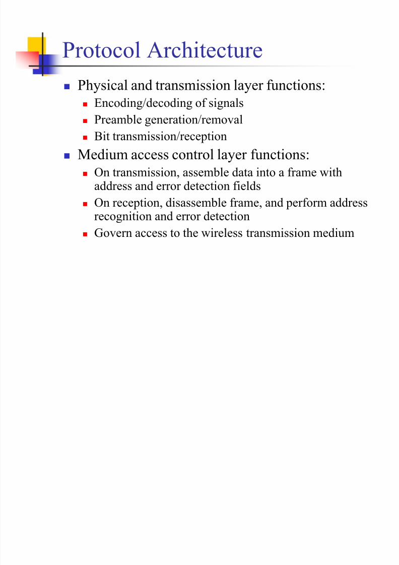
Protocol ArchitecturePhysical and transmission layer functions:
Encoding/decoding of signalsPreamble generation/removalB
it transmission/receptionMedium access control layer functions:
On transmission, assemble data into a frame withaddress and error detection fieldsOn reception, disassemble frame, and perform addressrecognition and error detectionGovern access to the wireless transmission medium

8/7/2019 Copy of CHAP11_rev
http://slidepdf.com/reader/full/copy-of-chap11rev 30/34
Protocol ArchitectureConvergence layer functions:
Encapsulate P D U framing of upper layers intonative 802.16 MAC/PHY frames
Map upper layer¶s addresses into 802.16addressesTranslate upper layer QoS parameters intonative 802.16 MAC format
Adapt time dependencies of upper layer trafficinto equivalent MAC service

8/7/2019 Copy of CHAP11_rev
http://slidepdf.com/reader/full/copy-of-chap11rev 31/34
IEEE 802.16.1 Services (air interface)
D igital audio/video multicastD igital telephony
ATMInternet protocolB ridged LA N
B ack-haulFrame relay

8/7/2019 Copy of CHAP11_rev
http://slidepdf.com/reader/full/copy-of-chap11rev 32/34
IEEE 802.16.3 Services
16.3 is the Air interface for LicensedFrequencies from 2 to 11 GHzVoice transportD ata transportB ridged LA N
8/7/2019 Copy of CHAP11_rev
http://slidepdf.com/reader/full/copy-of-chap11rev 33/34
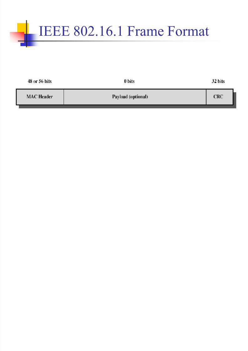
IEEE 802.16.1 Frame Format

8/7/2019 Copy of CHAP11_rev
http://slidepdf.com/reader/full/copy-of-chap11rev 34/34
IEEE 802.16.1 Frame FormatHeader - protocol control information
D ownlink header ± used by the base stationUplink header ± used by the subscriber to convey
bandwidth management needs to base stationB andwidth request header ± used by subscriber torequest additional bandwidth
Payload ± either higher-level data or a MAC
control messageCRC ± error-detecting code