Embed Size (px)
Citation preview
Copper Tube in Buildings
Copper Development AssociationVerulam Industrial Estate224 London RoadSt. AlbansHerts.AL1 1AQ
Telephone: 01727 731 200Facsimile: 01727 731 216e-mail: [email protected]: www.cda.org.uk
www.brass.org
Copper Tube in Buildings
CDA Publication Number 88.
MEMBERS, as at 1st January 2000
ASARCO Incorporated
Boliden MKM Ltd
Thomas Bolton Copper Products Ltd
British Non-Ferrous Metals Federation
Codelco Services Ltd
Gecamines
IMI plc
Noranda Sales Corporation of Canada Ltd
Rio Tinto London Ltd
Southern Peru Copper Corporation
Copper Development Association (limited by guarantee)
is a non-trading organisation sponsored by the copper
producers and fabricators to encourage the use of
copper and copper alloys and to promote their correct
and efficient application. Its services, which include the
provision of technical advice and information, are
available to those interested in all aspects of existing and
potential uses of copper. The Association also provides
a link between research and the user industries and
maintains close contact with other copper development
organisations throughout the world.
AcknowledgementsThe writing and reproduction of this publication is
financed by European Copper Institute, International
Copper Association Ltd, The UK Copper Board: IMI
Yorkshire Copper Tube Limited, Mueller Europe Ltd, IMI
Yorkshire Fittings Ltd, IBP Ltd and COMAP (UK) Ltd.

1 Technical and economic factors governing the use of copper tube in buildings
1.1 Resistance to corrosion1.2 Mechanical strength1.3 Ease of working1.4 Low pressure loss1.5 Bactericidal properties1.6 Favourable cost-effectiveness1.7 The material of the professional
2 Characteristics and parameters of copper tube
2.1 Characteristics of copper2.2 Mechanical properties of copper tube2.3 Dimensions of copper tube2.4 Packaging2.5 Marking2.6 Pressure losses and flow rate2.7 Working pressures2.8 Thermal expansion
3 General requirements for the use of copper tube
3.1 The various uses3.2 Contact with other metals3.3 Contact with other materials3.4 Behaviour of copper tubes in contact with different fluids3.4.1 Drinking water3.4.2 Softened water3.4.3 Deionised water3.4.4 Hydrazine and nitrites3.4.5 Household products3.4.6 Various chemical products3.5 Action of copper on drinking water
4 Working with copper tube
4.1 Cutting4.2 Annealing4.3 Bending4.3.1 Annealed and half-hard tubes4.3.2 Tube bending guide
5 Jointing of copper tubes
5.1 Ease of assembly5.2 Types of fitting5.3 Capillary fittings5.3.1 Use of capillary fittings5.3.2 Jointing without fittings5.3.3 Soft soldering5.3.4 Hard soldering5.4 Brazing and welding5.5 Compression fittings5.6 Push-fit fittings5.7 Press fit fittings
6 Installing copper pipework
6.1 General requirements6.2 Location of pipework and fittings6.3 Fixings6.4 Effects of expansion6.5 Pipework in screed or passing through walls6.6 Plastics coated pipework
1
1 Technical and economic factors governing the use of copper tube in buildings
2
Copper was used as a water conduit by the ancientEgyptians (at Abusir) as long ago as 2150 BC and was laterwidely used by the Romans as water pipes and cisterns.Indeed good examples of plumbing in copper are still tobe seen at the archaeological site of Herculaneum,destroyed by the eruption of Vesuvius in 79 AD.
The advantages of copper as a plumbing material wererediscovered at the beginning of the twentieth centurybut because the pipes were relatively expensive, theiruse was restricted to prestigious public buildings andhospitals, where the initial costs were outweighed by itsproven corrosion resistance, resulting in trouble freeservice and negligible maintenance costs. Coppertubing was expensive in those days because it couldonly be joined by threading and screwing, in a similarmanner to that used today for joining iron andgalvanised steel tubing. However in the 1930’s, with thedevelopment of different types of fittings and light gaugecopper tubing, which enabled the wall thickness to bereduced generally by over 50% and in some casesalmost 75%, costs were dramatically reduced.
Since the 1940’s, copper has become the pre-eminentplumbing material in the developed countries of theworld. In the UK it accounts for over 90% of newinstallations and its use is also increasing rapidly in thedeveloping countries. The reasons for this successderive from a combination of the properties of copper.
1.1 Resistance to corrosionCopper is highly resistant to corrosion not only from itssurroundings but also to the many different qualities ofwater conveyed. Indeed, as demands for improved waterquality have grown, and regulations governing the qualityof water have become more stringent, copper tubemanufacturers have developed their productiontechniques to meet these demands for higher quality tubes.
In the UK copper tubes are made in accordance with therequirements of British Standard BS EN 1057:1996. Onlythose manufacturers whose products are certified byregular checks from BSI Inspectors have the right to usethe “Kitemark” quality assurance symbol. In addition, theUK copper tube producers’ quality managementprocedures are inspected by BSI personnel to validatetheir continued registration as “registered” under therigorous criteria set out in BS EN ISO 9002:1994.
Copper tube made to these standards, properly installedby competent plumbers in well designed andmaintained systems will ensure long and trouble freeservice for the customer.
1.2 Mechanical strengthCopper tubes have high mechanical strength, at least
200 N/mm2 for annealed tubes and 250 N/mm2 for half-hard tubes. Copper tubes supplied in straight lengths arequite rigid and can be installed vertically or horizontallywithout sagging, with the minimum use of clips. Theyare resistant to most knocks and accidental damage.Copper’s high melting point and thermal conductivitymake copper tubes highly resistant to fire damage andthey are resistant to damage by rodents. All these factorsmake copper a very reliable material for tubes.
1.3 Ease of workingCopper is a very malleable metal and therefore can bebent and formed easily and quickly using appropriatetechniques. Lengths of tubing can be joined with fittingsusing simple soldering techniques and the variety offittings available allows even complex systems to beinstalled quickly and efficiently.
Copper tube also offers considerable aestheticadvantage. Indeed, whenever it is not possible toencase tubing or for any reason desirable to surface fixpipework, the use of copper including plastics coatedcopper tubing, reduces the visual impact to a minimum.
1.4 Low pressure lossPressure losses due to friction are lower for copper tubingthan for the majority of other metals. This is due to theinternal surface of copper tubing being relatively smooth.Other factors involved in achieving smooth flowcharacteristics of a copper system include the design offittings that do not restrict the cross-section of the boreand a larger bore for a given outside diameter comparedto other materials. Such factors reduce pressure loss byas much as 60% when compared with certain othermaterials. These characteristics, combined with the goodmechanical strength of copper, enable satisfactory flowperformances to be achieved with smaller diametertubes. The combination of all these advantages results ina reduction in: dimensions, the weight of metal used,costs and temperature lag in heating systems.
1.5 Bactericidal propertiesCopper has long been known for its algicidal andfungicidal properties. Work by International CopperAssociation has shown the decisive role which copper canplay in the destruction of certain bacteria. This work hasalready confirmed these properties and has shown to whatdegree copper tubing contributes to general health due toits natural purifying effects. There is evidence whichsuggests that substantially “all copper” systems tend to befree from the bacterium which causes Legionnaires Disease.
1.6 Favourable cost-effectivenessThe unique characteristics of copper piping combininglong trouble-free service life, safety and weight savingsdue to the ability to use smaller diameters readily
gas, water, sanitation and heating services withinbuildings. It is easy to use and install, entirely withoutdifficulties for a competent plumber. Indeed, the onlyrecommendations necessary which apply to the use ofcopper are those relating to good design of the systemsand a level of competent workmanship commensuratewith the use of any high-performance material. In thisrespect copper tubing is truly the material of theprofessional, for only he will know how to ensure thatthe natural long life of the product is not compromisedby poor design and faulty workmanship.
explain the success of copper in building applications.In addition, the ease of fabrication and installation ofcopper tubing, results in improved cost-effectiveness ofcopper compared with other metals.
This cost-effectiveness, resulting from the intrinsic propertiesof the metal, has been further enhanced in recent years bythe increased availability of copper throughout the world,which has contributed to a substantial lowering of costs.
1.7 The material of the professionalCopper tubing is manifestly a material well suited for
3
2 Characteristics and parameters of copper tube
2.1 Characteristics of copperThe copper used in the manufacture of tubes isphosphorus deoxidised copper Cu-DHP, designatedCW024A in accordance with EN 1412:1996 andPD 6641:1999.
The minimum copper content is 99.90% and theresidual phosphorus content is between 0.015 and0.040%. This deoxidisedcopper is not affected byreducing atmospheres andconsequently is well suitedto welding and brazing. Thedensity of copper is 8.9 g/cm3,its melting point is 1083°Cand its coefficient of linearexpansion is 16.8 x 10⁻⁶ per°C (between 20 and 100°C).
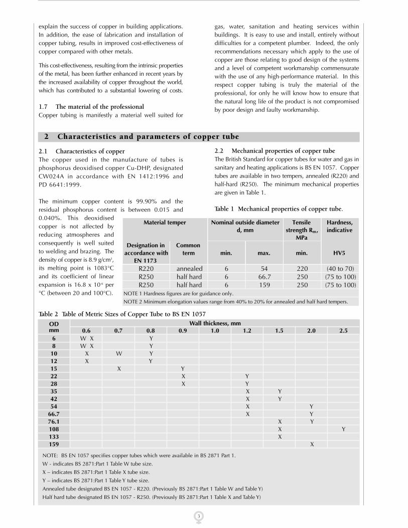
2.2 Mechanical properties of copper tubeThe British Standard for copper tubes for water and gas insanitary and heating applications is BS EN 1057. Coppertubes are available in two tempers, annealed (R220) andhalf-hard (R250). The minimum mechanical propertiesare given in Table 1.
Table 1 Mechanical properties of copper tube.
Material temper Nominal outside diameterd, mm
Tensilestrength Rm,
MPa
Hardness,indicative
Designation inaccordance with
EN 1173
Commonterm min. max. min. HV5
R220 annealed 6 54 220 (40 to 70)R250 half hard 6 66.7 250 (75 to 100)R250 half hard 6 159 250 (75 to 100)
NOTE 1 Hardness figures are for guidance only.
NOTE 2 Minimum elongation values range from 40% to 20% for annealed and half hard tempers.
Wall thickness, mm0.6 0.7 0.8 0.9 1.0 1.2 1.5 2.0 2.5
ODmm681012152228354254
66.776.1108133159
W X YW X Y
X W YX Y
X YX YX Y
X YX YX YX Y
X YX YX
X
Table 2 Table of Metric Sizes of Copper Tube to BS EN 1057
NOTE: BS EN 1057 specifies copper tubes which were available in BS 2871 Part 1.
W - indicates BS 2871:Part 1 Table W tube size.
X – indicates BS 2871:Part 1 Table X tube size.
Y – indicates BS 2871:Part 1 Table Y tube size.
Annealed tube designated BS EN 1057 - R220. (Previously BS 2871:Part 1 Table W and Table Y)
Half hard tube designated BS EN 1057 - R250. (Previously BS 2871:Part 1 Table X and Table Y)

● identification for half hard temper (R250) by ‘ ’
● manufacturer’s identification mark
● date of production: year and quarter (I or IV) or year and month (1 to 12)
The specification also requires that tube sizes less than10mm diameter and those greater than 54mm diametershall be similarly marked at both ends.
2.6 Pressure losses and flow rateCharts for calculating flow rate, velocity and pressure lossare given in Tables 3 and 4. Water velocities in a systemshould normally lie between 0.5 m/s, below which anysuspended matter may settle out, and 3 m/s, above whichnoise and/or corrosion-erosion damage may occur. If thepipe size originally chosen gives rise to velocities outsidethese parameters, a smaller or larger pipe size respectivelyshould be adopted. For hot water recirculating systemsthe maximum recommended water velocity is 1.5 m/s.
2.3 Dimensions of copper tubeThe dimensions of copper tubes to BS EN 1057 are givenin Table 2.
2.4 PackagingHalf hard tubes are normally supplied in straight lengthsof 3 or 6 metres. Tubes in the annealed condition aresupplied in coils. The length of tubing supplied as coilsis from 10 to 50 metres; the weight of a coil generallydoes not exceed 20kg.
2.5 MarkingOnly tubes manufactured by a firm licensed under the BSIscheme are permitted to carry the “Kitemark”. BS EN 1057requires detailed marking of the tubes of sizes 10 mm up toand including 54 mm diameter at intervals of not more than600 mm with at least the following information:
● EN 1057
● outside diameter x wall thickness
4
Pres
sure
Dro
p N
/m2
per
met
re
Flow Kg/sec.
Table 3 Water flow resistance through half-hard (R250) copper tube, (formerly Table X).

P = 20FtD-t
Where P = maximum working pressure (bar)
F = design stress (N/mm2)
t = minimum wall thickness (mm)
D = maximum outside diameter (mm)
For 1/2 Hard, R250, condition F = 60 N/mm2.For annealed, R220, condition F = 46 N/mm2.
● If tubes in the 1/2 H condition are annealed, e.g.during brazing or hard soldering, the stress valuequoted above for condition annealed should beused for calculating working pressures.
● Copper tubes are suitable in some circumstancesfor use up to a maximum temperature of 200°C,
Table 4 Water flow resistance through annealed (R220) and half-hard (R250) copper tube, (formerly Table Y).
5
The resistance to flow of fittings must also be taken intoaccount when designing systems and the simplest wayto do this is to regard each fitting as an equivalent lengthof the appropriate size of tubing. Equivalent lengths forfittings corresponding to R220 and R250 copper tubeare given in CDA publication 33. For example, for a runof 10 metres of 15mm R250 tubing containing 4capillary elbows, in a cold water service (15.5°C) theequivalent length would be 10 + (4 x 0.31) metres i.e.11.24 metres.
In the case of tees etc., the flow direction must also betaken into account using the appropriate values fromAppendix H in publication 33.
2.7 Working pressuresThe maximum working pressures at temperatures up to65°C are calculated in accordance with the followingformula:
Pres
sure
Dro
p N
/m2
per
met
re
Flow Kg/sec.

Tube length, Temperature difference ∆t °C
m ∆t = 30° ∆t =40° ∆t=50° ∆t =60° ∆t =70° ∆t =80° ∆t =90° ∆t =100°
0.1 0.05 0.07 0.08 0.10 0.12 0.13 0.15 0.17
0.2 0.10 0.13 0.17 0.20 0.24 0.27 0.30 0.34
0.3 0.15 0.20 0.25 0.30 0.35 0.40 0.45 0.50
0.4 0.20 0.27 0.34 0.40 0.47 0.54 0.60 0.67
0.5 0.25 0.34 0.42 0.50 0.59 0.67 0.76 0.84
0.6 0.30 0.40 0.50 0.60 0.71 0.81 0.91 1.01
0.7 0.35 0.47 0.59 0.71 0.82 0.94 1.06 1.18
0.8 0.40 0.54 0.67 0.81 0.94 1.08 1.21 1.34
0.9 0.45 0.60 0.76 0.91 1.06 1.21 1.36 1.51
1.0 0.50 0.67 0.84 1.01 1.18 1.34 1.51 1.68
2.0 1.01 1.34 1.68 2.02 2.35 2.69 3.02 3.36
3.0 1.51 2.02 2.52 3.02 3.53 4.03 4.54 5.04
4.0 2.02 2.69 3.36 4.03 4.70 5.40 6.05 6.72
5.0 2.52 3.36 4.20 5.04 5.88 6.72 7.56 8.40
10.0 5.04 6.72 8.40 10.08 11.76 13.44 15.12 16.80
15.0 7.56 10.08 12.60 15.12 17.64 20.16 22.68 25.20
20.0 10.08 13.44 16.80 20.16 23.52 26.88 30.24 33.60
25.0 12.60 16.80 21.00 25.20 29.40 33.60 37.80 42.00
but for pressure calculations a stress valueappropriate to the particular temperature should beused, see Table 5.
Table 5 Stress values for working temperatures inexcess of 65°C
6
Temperature °CMax. admissable stressfor annealed, R220,condition, N/mm2
40 34 26 18
110 150 175 200
2.8 Thermal expansionTable 6 shows the increase in length due to thermalexpansion as a function of change in temperature ∆t andthe length of the tube at the lower temperature,irrespective of temper or wall thickness. (Coefficient oflinear expansion 16.8 x 10⁻⁶ per °C).
3 General requirements for the use of copper tube
3.1 The various usesCopper tubes are generally used in buildings for the
following services:
● Domestic hot and cold water supplies under
pressure, usually up to mains pressure (typically
60 psi or 4 bar or maybe up to 10 bar) or head
pressure from a storage tank
● Sanitary waste water drainage
● Wet central heating systems (with radiators/
convectors)
● Underfloor heating
● Gas services for heating and cooking
● Oil services for heating
Copper tubes and fittings are also suitable and widely used
for the following services:
❍ Chilled water and refrigeration
❍ Fire sprinkler systems
❍ Air conditioning
❍ Steam
❍ Medical gases
❍ Pneumatics
❍ Hydraulics
❍ Waste water
These various applications impose as many stresses on the
tubes as the different conditions of use. Such as:
Table 6 Thermal expansion (mm) of copper tube as a function of tube length and temperature difference.

ferrous components and galvanic corrosion is minimal.In a direct hot water system or where there is significantingress of oxygenated water (e.g. due to over-pumping orleakage) ferrous components, such as steel radiators mayfail quite rapidly. Whilst steel radiators may fail due toother factors, such as excess flux residues from solderedjoints being washed in, over 90% of all steel radiatorfailures are due to the ingress of oxygen into the primarysystem. A typical galvanic series is given in Table 7.
Table 7 Galvanic series of metals and alloys
● Wide variations of pressure
● Expansion/contraction phenomenon due totemperature variation
● Chemical attack due to external materials or thecharacteristics of internal fluids
● Stresses imposed on the tubes during installation(or manufacture)
It is therefore important to know details of theenvironment to which the pipework will be exposed andalso the stresses to which it will be subjected in order toassess the behaviour of the tubes.
3.2 Contact with other metalsWhenever two dissimilar metals are in contact, in anelectrolyte containing dissolved oxygen, the assemblyconstitutes a galvanic (corrosion) cell in which the morenoble metal is the cathode and the less noble metal isthe anode, which tends to dissolve (corrode). Aconsequence of this is that the more noble metal iscathodically protected by the less noble (base) metal.For example galvanised (i.e. zinc coated) steel isprotected by the preferential corrosion of the zinccoating and does not show significant rusting until thedissolution of the zinc coating is virtually complete.
With the exception of iron and steel components upstreamof copper, when no undue corrosion will be experienced, inpipework carrying fresh water, the jointing of copper to ironor steel should be avoided as far as is possible, otherwise theiron or steel component will corrode preferentially. Thecorrosion of steel tanks commonly connected to copperpipes is reduced by the insertion of electrically insulatingwashers and also by the relative size of the exposed surfaces,in this case a large anode and a small cathode. A steel pipeattached to a copper tank or cylinder will corrode at asignificantly greater rate since the relationship is one of largecathode and small anode. Similarly, iron or steel should notbe installed downstream of copper in a fresh water circuitotherwise rapid corrosion of the iron or steel will occur. Theconductivity of the water (electrolyte) also influences the rateof corrosion in that the higher the conductivity of the water,the greater will be the rate of any corrosion.
It should be stressed that galvanic corrosion does notoccur in the absence of an electrolyte i.e. in a dryenvironment, so that the use of steel clips on a copperpipe will cause no problem. The steel clips may corrodepreferentially, however, if the environment is prone tocondensation e.g. a cold water pipe in a steamy (humid)atmosphere such as a kitchen.
The presence of dissolved oxygen in the water is afundamental factor in galvanic corrosion within systems.In the primary circuit of an indirect heating system wherethe water continuously circulates for example, theoxygen is quickly used up in superficial corrosion of the
7
Corroded end: anodic – least nobleZinc99% aluminiumAluminium-copper alloysSteel or ironCast ironChrome-iron (active)Stainless steel (active)Lead-tin soldersLeadTinBrassesCopperBronzesCopper-nickel alloysSilver solderChrome-iron (passive)18/8 Mo chromium-nickel austenitic steel (passive)SilverGraphiteProtected end: cathodic – most noble
In practice galvanic corrosion is not a serious problemunless the potential difference is greater than about200mV, (the 1/4 volt criterion).
3.3 Contact with other materialsCopper is highly resistant to corrosion by mosttraditional building materials such as brick, plaster orconcrete based on Portland cement. However, it shouldnot be allowed to come into contact with acid plasters,acid cements or coke breeze.
Except for underfloor heating systems the installation ofcopper tubes or fittings within solid walls or floors is notrecommended, unless they can be readily exposed, oralternatively if installed in a sleeve or duct where theymay be readily removed or replaced. Any tubes passingthrough solid walls (by the shortest route) must besleeved. Unprotected copper pipes should not be laidin screeds containing ammoniacal foaming agents norallowed to come into contact with cleaning fluids,which may contain ammonia or its derivatives.
Copper also has high corrosion resistance to attack by soils,but again there are well known conditions that areaggressive to all metals, even to copper. These include“made-up” ground containing wet ashes or clinker, poorlydrained sites with a high chloride or sulphate content or wet

3.4.3 Deionised waterDeionised water is equivalent to distilled water, both anionsand cations having been removed by ion exchange resins.It is to some extent aggressive to all but the exotic metalse.g. gold, platinum etc., and if required as pure water itshould be conveyed in glass or other suitable materials.
If it is used as a heat transfer fluid, e.g. in airconditioning equipment, an appropriate inhibitor, suchas benzotriazole should be added and the inhibitor levelchecked periodically to avoid corrosion.
3.4.4 Hydrazine and nitritesHydrazines or nitrites are sometimes added to heatinginstallations as corrosion inhibitors in mixed metalsystems to avoid galvanic corrosion. Both may beconverted to ammoniacal species, by breakdown orreduction, which can give rise to the corrosion of copperor its alloys (e.g. brass). When corrosion occurs theconcentration of the inhibitor is often reduced, but this isprecisely the wrong action, since ammonia is notaggressive to copper in the absence of oxygen and sincehydrazine and nitrites are oxygen scavengers, theirconcentration should be increased to between 4 and 7times the value of the dissolved oxygen content (in ppm.).
3.4.5 Household productsThere are several household products currently availablethat can attack copper, such as ammonia solutions andhypochlorite bleaches. Cleansers containing ammoniashould not be allowed to come into contact with copperotherwise the copper tubing will blacken, or even showevidence of bright blue cuproammonium salts. Copperis not unduly susceptible to stress corrosion cracking.However, when in contact with these chemicals there isa risk of cracking in tubes that contain residual tensilestresses. Clearly hard and half-hard tubing is at greaterrisk than annealed tubing, but any brass compressionfittings offer the greatest risk, especially anycompression nuts that have been over-tightened. Thisapplies particularly when cleaning floors in kitchensetc., where pipes are buried beneath the floor.
Cleansers containing hypochlorites should be used withcare, for whilst hypochlorite solutions are excellentsterilising agents and widely used for this purpose, thestrength of solution and exposure times need to becarefully controlled. To avoid any risk of attack, thestrength of solution should be limited to 50 ppm freechlorine for a period of no more than 1 hour, (BS 6700).Sterilising solutions should not be left in systemsovernight and when the process is complete, the systemshould be washed through with fresh water until theresidual free chlorine level is down to 1-2 ppm. Similarly,the practice of leaving such cleaners in urinals and wastepipes overnight should be discouraged. Specificallydesigned toilet cleansers however based on “nitre cake”(sodium hydrogen sulphate) do not attack copper.
soils containing decaying vegetable matter or nitrogenousfertilisers. Furthermore, the laying of underground servicesin contact with contaminating materials such as foul soils, orpassing through any sewer, drain or cesspit is prohibited.Underground services should be installed using thick walledcopper tube, (formerly designated Table Y) and all the fittingsshould be immune or resistant to dezincification. Anycompression fittings should be of the manipulative type toBS EN 1254: Part 2, Type B.
Unless the building materials or soils are known to be non-aggressive to copper, it is advisable to use factory suppliedplastics coated copper tube or to protect the tubes andfittings by means of a suitable waterproof wrapping.
3.4 Behaviour of copper tubes in contact with different fluids
3.4.1 Drinking waterCopper is highly corrosion resistant to potable waterwhich complies with “EC Directive relating to theQuality of Water intended for Human Consumption”and World Health Organisation “International Standardsfor Drinking Water” and provided according to theWater Act of 1989.
In some areas where the water is particularly “soft” andmay tend occasionally toward the acid side of neutral, newinstallations of copper tubing may give rise to the stainingof sanitary ware and copper pick-up, resulting in a slightlymetallic, astringent taste to the water. As mentioned laterin 3.5, copper is not a toxic metal under thesecircumstances and the taste problems can be avoided byrunning the tap for a few minutes to clear the pipes. Thecondition will slowly improve as protective films build upon the inside surface of the tubes. In some waters this maytake weeks or even a few months, but if it persists longerthan this, expert advice should be sought with a view toincreasing the hardness of the water supply concerned.
Some years ago, corrosion problems were encountered inhard, organically pure cold water supplies, invariably deepwell or bore-hole derived, due to residues of carbonproduced on the inside surface of tubes during manufacture.Many years of research and development in the UK haveensured that “Kitemarked” tubing is free from carbon films.
3.4.2 Softened waterHard waters may be softened to avoid excessive depositsof scale in boilers and hot water services by replacinginsoluble calcium and magnesium salts with solublesodium salts. However, softening should be carried outwith care since the softened water is almost always moreaggressive than the raw water concerned. Since there isno virtue in softening the cold water, indeed thesoftening of water to kitchen and drinking water taps isprohibited, only cold supplies to hot services should besoftened and then only to a minimum total hardness of60 ppm. as CaCO3, by means of a valved by-pass system.
8

are not commonly found in the domestic situation.Table 8 gives general information on the suitability ofcopper with various chemicals.
3.4.6 Various chemical productsCopper tubes are widely used in industry and they maycome into contact with many different chemicals that
9
Table 8 Suitability of copper with various chemicals
Acetic (Acid) B Chromic Acid D Oxalic Acid C Acetic (Anhydride) B Cider A Oxygen** AAcetone A Citric Acid C Oxygenated water B Acetylene (see note 1) D Coffee A Palmitic Acid* B Alcohols A Copper Chloride C Paraffin Wax A Alum B Copper Nitrate C Phosphoric Acid C Alumina A Copper Sulphate B Potash B Aluminium Chloride B Corn Oil* A Potassium Carbonate B Aluminium Hydroxide A Cottonseed Oil* A Potassium Chloride B Aluminium Sulphate B Creosote A Potassium Chromate B Ammonia Gas (Dry) A Crude Oil (Low Sulphur) A Potassium Cyanide D Ammonia Gas (Wet) D Drinking Water A Potassium Sulphate A Ammonium Hydroxide D Ethers A Propane A Ammonium Chloride D Ethyl Acetate A Rosin A Ammonium Nitrate D Ethyl Chloride B Seawater C Ammonium Sulphate D Ethylene Glycol (Inhibited) A Silver Salts D Amyl Acetate A Ethyl Alcohol A Soaps (Solutions of) B Amyl Alcohol A Ferric Chloride D Sodium Bicarbonate B Aniline D Ferric Sulphate D Sodium Bisulphate B Aniline (Dyes) C Ferrous Chloride C Sodium Bisulphite B Asphalt (Dry) A Ferrous Sulphate C Sodium Carbonate B Atmosphere (Industrial) A/B Fluorosilicic Acid C Sodium Chloride B Atmosphere (Marine) C Formaldehyde B Sodium Chromate B Atmosphere (Rural) A Formic Acid B Sodium Cyanide D Barium Carbonate A Freon A Sodium Hypochlorite C Barium Chloride B Fruit Juice B Sodium Nitrate B Barium Hydroxide A Fuel Oil A Sodium Peroxide C Barium Sulphate A Furfural B Sodium Phosphate B Barium Sulphide C Gasoline A Sodium Silicate A Benzene A Gelatine A Sodium Sulphate A Benzine A Glucose A Sodium Sulphide C Benzoic Acid D Glue B Sodium Hyposulphite D Beer A Glycerine A Solvents for Varnish A Bordeaux Mixture A Hydrobromic Acid D Steam A Borax A Hydrocarbons (Pure) A Stearic Acid* B Boric Acid A Hydrochloric Acid D Sugarbeet (Syrup) A Brine C Hydrocyanic Acid D Sulphur (Dry) B Bromine (Dry) A Hydrofluoric Acid D Sulphur (Molten) D Bromine (Wet) C Hydrogen A Sulphur Chloride (Dry) A Butane A Hydrogen Sulphide (Dry) A Sulphurous Anhydride (Dry) A Butyl Alcohol A Hydrogen Sulphide (Wet) D Sulphurous Anhydride (Wet) B Butyric Acid B Kerosene A Sulphuric Anhydride (Dry) A Calcium Chloride C Lacquers A Sulphuric Acid (80/95%) D Calcium Disulphide B Lactic Acid B Sulphuric Acid (40/80%) D Calcium Hydroxide A Lime A Sulphuric Acid (<40%) C Calcium Hypochlorite C Linseed Oil* B Sulphurous Acid C Cane Sugar Syrup A Magnesia A Tannic Acid B Carbolic Acid C Magnesium Chloride B Tar (Dry) A Carbon Tetrachloride (Dry) A Magnesium Sulphate A Tartaric Acid C Carbon Tetrachloride (Wet) B Mercury (and its salts) D Toluene A Carbon Dioxide (Dry Gas) A Methyl Chloride (Dry) A Trichloroacetic Acid C Carbon Dioxide (Wet Gas) D Methyl Alcohol A Trichloroethylene (Dry) A Castor Oil A Milk* A Trichloroethylene (Wet) B Caustic Soda B Mine Water (Acid) C Turpentine A Chlorine (Dry) A Natural Gas A Varnish A Chlorine (Wet) D Nitric Acid D Vinegar C Chloroacetic Acid C Nitrogen A Zinc Chloride C Chloroform A Oleic Acid C Zinc Sulphate C
A = Resistant to corrosionB = Resists corrosion wellC = Undergoes slow corrosionD = Copper is not to be recommended in the presence of thesubstance considered
Note 1: Copper alloys containing more than 70% copper cannotbe used for handling acetylene.
* = Product may deteriorate (auto-oxidation)
** = Tube must be grease free.

rather, it is a desirable “trace element”, the human bodyrequiring about 2.5 to 5 mg/day to maintain normalhealth. Lead, on the other hand, which was widelyused for plumbing services in the last century and thebeginning of the present century, and may still bepresent in older installations, is known to beparticularly toxic.
3.5 Action of copper on drinking waterAs mentioned previously in 3.4.1, copper is entirelysuitable for use with potable water as defined by EUregulations and WHO guidelines. These also specify thatthe copper content of the water does not exceed 2 mg/l.
Copper is often erroneously considered a toxic metal,
10
4 Working with copper tube
4.1 CuttingSmall diameter pipes, up to 12 mm OD are best cut witha junior hacksaw but it is usually more convenient to usea tube cutter for 15, 22, 28 and 35 mm sizes.Alternatively, and for larger size pipes, a fine toothedhacksaw (32 teeth per inch) can be used. Where manylengths are to be cut power hacksaws, circular saws(with a fine, metal cutting blade) or abrasive cuttingdiscs may be used. Whatever method is used, the toolsmust be sharp and in good condition to avoid distortionof the tube end. All ends must be cut square and bothinternal and external burrs carefully removed using a fileor reamer. When using a tube-cutter care must be takento avoid distortion (“nozzling”) which can not onlyinduce turbulence and/or restrict water flow, but alsoreduce the strength of a capillary joint. If necessary tubeends should be re-rounded using a suitable tool and inthe case of coils in the annealed condition, re-roundingshould always be carried out, to avoid any ovality whichcould adversely affect the strength of the capillary joint.
4.2 AnnealingIt is sometimes necessary to anneal half-hard tube in thelarger sizes, to facilitate specialist bending or forming.To achieve this, the tube is heated to a dull red heat (600°C)and is either allowed to air cool or may be quenchedimmediately in cold water. Care should be taken not toexceed the annealing temperature (600°C) as this couldgive rise to grain growth (the so-called “orange peel”effect) which can significantly adversely affect theproperties, including ductility, of the tubing.
4.3 Bending4.3.1 Annealed, R220, and half-hard, R250, tubesCopper tubes in the annealed or half-hard condition areeasily bent by using bending techniques appropriate tothe size and temper of the tubes.
Suitable flexible bending springs, used either externallyor internally as appropriate, manufactured inaccordance with BS 5431 are available for standard sizestraight tubes from 10 to 22 mm. Only relatively easybends, over the knee or a suitable former should beattempted and to a minimum radius of 5 times thediameter of the tube to the inside of the bend (rootradius).
Figure 1 Hand bender
Figure 2 Bending machinePortable bending machines, suitable for bending tubesup to and including 54 mm OD are readily available,indeed some smaller benders, up to 22 mm can becarried in a tool kit. For tube sizes larger than 54 mm,fixed power benders are the only satisfactory option.
All bending machines work on the principle that thetubing is bent between matched formers and backguides, which support the OD of the tubing, thuseliminating the risk of collapse of the tube wall.However, the point at which the bending pressure isexerted on the tube is critical. This point must be

may have a fixed or “floating” mandrel and are oftenautomated for production runs.
The practice of sand loading and/or hot bending of tubes isnow redundant, since it is more convenient and satisfactoryto bend cold by one of the methods given above.
It should be noted that bending tubes greater than54mm diameter and forming tight radius bends (i.e. withinside radius less than 3 times the tube diameter) aregenerally considered to be specialist operations andreference should be made to equipment and productmanufacturers.
4.3.2. Tube bending guideTable 9 Tube bending guide
maintained at an optimum distance in front of the pointof support on the former, but if this distance is too smallexcessive throating of the bend will occur or if it is toogreat, corrugations will appear in the inner radius of thebend and flattening of the outside of the bend will occur.On a correctly set up bending machine the lever armwill be at right angles to the tube that is to be bent. It isrecommended therefore that adjustable bendingmachines are used, since these permit the pressure onthe back guide to be adjusted and so accommodatemachine wear to form perfect bends every time.
Severe corrugations or flattened bends can adverselyaffect flow conditions in service, potentially giving riseto localised impingement (corrosion erosion) or, in hotservices, to fatigue cracking resulting from stresses set upby thermal movement being concentrated at thecorrugations, (a “notch” effect) whereas a smooth bendwill absorb such stresses without damage.
The radius of bends formed on machines will naturallydepend on the dimensions of the former supplied.Where particularly tight bends and/or full bore bends tothe original OD throughout the bend are required, amore sophisticated machine using a mandrel to supportthe tube internally is recommended. Such machines
11
OutsideDiameter (mm)
Minimumbending radius*
Method ofbending
<10 3 times the OD External springBending machine
>10, <22 3 times the OD Internal springBending machine
>22 3 times OD Bending machine*Bending radius is the root radius, i.e. tube bend inside radius.
Hard drawn tube greater than 18mm diameter is generallynot suitable for bending.Spring bending of coils is not recommended.
5 Jointing of copper tubes
5.1 Ease of assemblyIn addition to the corrosion resistance of copper and itsphysical properties, which allow it to be manipulatedeasily, possibly the greatest single advantage in installingcopper tube is the ease with which it can be joined. Thefittings, which are available world wide and in a widevariety include straight connectors, elbows and tees thusenabling even complex installations to be carried out easilyand quickly, thereby greatly reducing installation costs.
5.2 Types of fittingFittings fall into two main categories, capillary andcompression types, with a new third category of push-fitand press-fit fittings.
5.3 Capillary fittings5.3.1 Use of capillary fittingsThe capillary fitting utilises the force of capillary actionto ensure that molten solder, or brazing alloy, is drawninto the gap between the outside surface of the tube andthe inside surface of the socket of the fitting to producea very strong joint. The strength of the joint, whencorrectly made, is invariably stronger than the tube.Indeed in tensile and pressure tests to destruction thetube invariably breaks before the joint.
To achieve proper capillary flow, the gap between tubeand fitting must be within specified tolerances which are
provided by the dimensional requirements of BS EN1057 for tubes and BS EN 1254 for fittings.
There are two types of capillary fitting, one contains anintegral solder ring in each socket of the fitting, whilstthe second, the end-feed type, requires solder or brazefiller to be applied to the mouth of the socket when theassembly has been heated to soldering temperature.
Figure 3 Capillary fittingsWhilst an integral solder ring fitting is usually moreexpensive than an end-feed type, it is easier and quicker

an integral solder ring fitting, the joint is then heatedwith a propane or butane/air blow lamp, or for largersize pipework an air/acetylene or oxy/acetylene torch,until a complete ring of molten solder appears aroundthe mouth of the socket. At this point the heat source isremoved and the joint is allowed to cool withoutdisturbance until the solder re-solidifies.
With an end-feed fitting, the joint is heated to the meltingpoint of the solder and the heat source removed. Onapplying the solder rod or wire to the mouth of the fittingthe solder should melt on contact with the tube and fillthe capillary gap until a complete solder ring appears.The joint is then left to cool without disturbance.
Several types of solder and brazing alloy are available,depending on the service required.
In order to ensure that joints in potable water servicescannot contaminate the water with lead, tin/copper ortin/silver solders, with melting points of about 230 to240°C, must be used. Tin/lead solders, with a meltingpoint of about 220°C, could be used for gas or centralheating services, but it is recommended that only lead-free solders are used throughout an installation in orderto avoid any risk of inadvertent mixing of solders.
For low temperature services e.g. chillers or refrigerationcircuits, tin/silver solders are recommended, whilst forany joints in underfloor heating circuits, copper-silver-phosphorus brazing alloys are recommended.
The integrity and strength of capillary joints are greatlydependent on the uniformity of the capillary gap andtherefore not only must the tubes and fittings becompatible, but also the tube ends must be free fromsignificant deformation and ovality. It is therefore goodpractice to re-round tube ends after cutting and de-burring, even on half-hard and hard drawn tubes, ifany distortion is apparent. On annealed, coiled, tubingwhere ovality and distortion are almost inevitable, re-rounding after deburring is of vital importance.
For soft solders there are several different types of flux,the purpose of the flux is to chemically clean the metalsurface and also prevent re-oxidation of the surfaceduring heating to enable the solder to run and “wet” thesurfaces to be joined. Ideally a flux should only beaggressive to the metal concerned at solderingtemperatures, but this is difficult to achieve in practice.
Fluxes containing organic chlorides, bromides or zincand/or ammonium chlorides, emulsified in a greasebase, such as petroleum gel, are those most commonlyused in plumbing. They are all to some extent corrosiveto copper, otherwise they would not clean the metalsurfaces, and therefore must be used sparingly and anyexcess removed when soldering is completed. They
to install and because no extra solder is required, theinstalled costs of the two types of fittings are similar.Indeed the only real advantage of the end-feed fitting isthat a different type of solder or a brazing alloy such ascopper (silver) phosphorus, may be used in specialcircumstances. A further advantage of ISR is that thesolder is guaranteed lead free.
5.3.2 Jointing without fittingsCopper tubes can be joined without using a fitting byexpanding the end of one tube to form a socket andinserting the end of another tube of the same diameter.This is achieved by using a precision expander, whichforms a socket of similar internal dimensions to thesocket of a fitting made to BS EN 1254 and the joint ismade in precisely the same manner as an end-feedfitting. The economics of this type of joint are clearlydependent on the skill and labour costs of the operative.
Figure 4 Jointing without fittingsBranches may also be formed by drilling through thetube wall and opening it out to form a socket to whichanother tube is brazed. However, without specificequipment this process is relatively time consuming andrequires the specialist skills of a copper-smith, generallybeyond the scope of the average plumber and isconsequently only used in special circumstances.
5.3.3 Soft solderingWhether an integral solder ring or end-feed type ofcapillary fitting is used, the method of preparing the tubeand fitting is the same. The tube end must be cut squareand deburred both internally and externally. The outsidesurface of the tube end, to the depth of the socket, andthe inside surface of the socket in the fitting are abradedwith a cleaning pad and the outside of the tube smearedwith a thin film of flux, preferably using a small brush,not a finger.
The tube end is then inserted into the socket, with aslight twisting motion to spread the flux evenly and anyexcess flux is wiped from the mouth of the socket. With
12
Socket forming forequal diameter tubes
Connections of tubes withdifferent diameters
Expander
Socket joint Branched joint

Type “A” non-manipulative compression fittings,manufactured to BS EN 1254 Part 2 Type “A”, as thename implies, do not require any manipulation of thetube end prior to installation. The joint is made bytightening a compression ring or sleeve onto the outsideof the tube when the compression nut is tightened ontothe body of the fitting. This type of fitting can be usedon straight lengths of half-hard tubing but only up to 12 mm OD on coiled annealed tubing unless a suitablesupporting sleeve is provided.
The fittings are approved for surface fixing or wherereadily accessible (in ducts etc.). Jointing is carried outvery simply as follows:
1. Cut the tube end square using a tube-cutter.
2. Remove both internal and external burrs.
3. Re-round tube ends if necessary. (Always onannealed tube.)
4. Slip compression nut and then compression ringonto tube
5. Insert tube end into fitting up to the tube stop.
6. Tighten the compression nut finger tight and thenfully tighten with an appropriate size spanner bythe number of turns recommended by the fittingsmanufacturer.
Jointing paste should not be necessary, indeed it mayinterfere with the integrity of the metal to metal joint.Reference should be made to manufacturer’srecommendations.
Figure 5 Compression fittingsType “B” manipulative compression fittings require theend of the tube to be flared, cupped or belled with aspecial forming tool (in some cases supplied by thefittings manufacturer) after the end of the tube has beencut square. The formed end of the tube is compressedagainst a corresponding section of the fitting, or againsta loose thimble, when the correspondingly shapedcompression nut is tightened.
should be spread as a thin film, preferably using a smallbrush, over the cleaned tube surface, taking care not toallow flux to creep into the bore. When a section ofpipework has been completed, it should be flushed outwith water to remove any excess flux residues.
The so called “self-cleaning” fluxes contain freehydrochloric acid and whilst they are excellent fluxesthey should be used with extreme care, in accordancewith the manufacturers instructions and any excessremoved after jointing.
5.3.4 Hard solderingFor installations that operate at higher temperatures orpressures than can be tolerated by soft soldered fittingse.g. steam services, or where grease-based fluxes areprohibited e.g. oxygen lines, a range of high-duty fittingsis available. High-duty fittings usually contain integralrings of silver brazing alloy, though end-feed types arealso available. Only the fluxless brazing alloys areallowed for oxygen lines.
The silver brazing alloy used melts at a temperaturegreater than 650°C (cherry-red heat), requiring the useof an oxy/acetylene, oxy/propane or acetylene/air torchand since this is above the annealing temperature ofcopper all pressure calculations must be based on thestress value for the annealed, R220, condition. A specialborax-based flux is used.
Copper-silver-phosphorus filler metals, (which shouldnot be used on ferrous metals, nickel based alloys orcopper alloys containing nickel), are used in much thesame way as soft solders, except that their melting pointsare higher (645 to 800°C). No flux is required however,since the phosphorus content of the alloy is an effectivede-oxidiser. These are preferred for medical and oxygengas lines.
5.4. Brazing and weldingCopper tubes may also be joined by brazing orautogenous welding, using suitable alloy filler rods, butsuch methods are not normally applicable toconstruction sites.
It should be noted that the composition of the filler rodsmust be carefully selected to avoid any risk ofpreferential corrosion or de-alloying of the joint fillet,such as dezincification.
Care must also be taken to avoid prolonged overheatingduring jointing, since this could lead to grain growth, oreven localised melting with the melting point of some ofthe brazing alloys being above 800°C.
5.5 Compression fittingsCompression fittings are available in two types, eachtype being primarily designed for specific usage.
13
Fitting body
Adaptor
Compressionring
Compressionnut
Fitting body(gunmetal)
Compressionring
Compressionnut
(gunmetal)
Type “A”
Type “B”

applied to the release collar in the mouth of the fitting,using a special disconnecting tool, which splays theteeth of the grab ring. Thus the tube is freed from thefitting. Other types require a securing cap to beunscrewed.
Push-fit fittings are suitable for all above ground hot andcold domestic water services, including both direct andindirect heating systems. They are also ideal for use insmallbore and microbore central heating systems and inpressurised unvented heating systems within thepermitted temperature and pressure limits.
Press-fit fittingsPress-fit fittings are another new type of fitting requiringa special compression tool. The fitting is slid over thetube and mechanically crimped between the body of thefitting and the ‘O’ ring seal at the end of the fitting. Thetube must be prepared as for a push-fit fitting in order toensure the ‘O’ ring is not damaged. This type of joint isquick and effective requiring no spanners or flame butdoes require the special tool.
Manipulative compression fittings are not suitable foruse with hard tubes and annealed tubes must becarefully deburred and re-rounded before the tube endis formed. This type of fitting, to BS EN 1254: Part 2 Type“B”, must be used for underground installation andtherefore must be made from dezincification resistant orimmune materials.
5.6 Push-fit FittingsPush-fit fittings are new, reliable and versatile. As the tubeis inserted into the fitting in several types it passes througha release collar and then a stainless steel grab ring. Thegrab ring has a series of teeth that open out and grip ontothe outside of the copper tube. A support sleeve inside thefitting will help in alignment of the tube and when the tubeis fully inserted, to the tube stop, an ‘O’ ring is compressedbetween the wall of the fitting and the tube. For a securejoint to be formed the tube must pass through the ‘O’ ringand reach the tube stop. In some push-fit fittings theposition of the ‘O’ ring and grab ring are reversed.
Most of these fittings can be disconnected, and theoperation is as simple as forming the joint. Pressure is
14
6 Installing copper pipework
The general specification for the design, installation, testingand maintenance of services supplying water for domesticuse within buildings and their curtilages is BS 6700.
6.1 General requirementsTo ensure long and trouble-free service life, coppertubes and fittings should be installed with due care in aproper workmanlike manner. Circuits should bedesigned to operate at optimum flow conditions, i.e. forcold water circuits between 0.5 and 3 metres per secondand for hot water recirculating systems between 0.5 and1.5 metres per second. They should be arranged in sucha manner that “dead-legs” are kept to an absoluteminimum. Joints should be made carefully to avoidexcess flux residues both from entering the system andcontaminating the exterior. Each section of a largecircuit should be flushed through after completion toremove flux and debris.
In hot water services and central heating systems, tubesmust be fixed in a manner that allows thermalmovement, i.e. expansion and contraction withoutimposing undue stress on the tubes and fittings.
The more important specifications covering the use ofcopper tubes in buildings are detailed below:
BS EN 1057: Copper and copper alloys – Seamless,round copper tubes for water and gas in sanitary andheating applications.
BS EN 1254: Copper and copper alloys – Plumbing
fittings
Part 1: Fittings with ends for capillary soldering or
capillary brazing to copper tubes.
Part 2: Fittings with compression ends for use with
copper tubes.
Part 4: Fittings combining other end connections with
capillary or compression ends.
BS 1306: 1975 (1983): Specification for copper and
copper alloy pressure piping systems.
BS 5431: 1976 (1987): Specification for bending springs
for use with copper tubes for water, gas and sanitation.
BS 6700: 1997: Specification for the design, installation,
testing and maintenance of services supplying water for
domestic use within buildings and their curtilages.
BS EN ISO 9002 Quality systems. Model for quality
assurance in production, installation and servicing.
These are available from British Standards Institution.
Further detailed information is contained in CDA
Publications:
33 – Copper Tube in Domestic Water Services.
39 – Copper in Domestic Heating Systems.

heating installations the limited size of rooms and hencestraight pipe runs, together with the many bends andoffsets that normally occur will result in thermalmovement being accommodated automatically.However where long straight pipe runs, exceeding 10m,are encountered, allowance for expansion should bemade.
Expansion bellows and expansion loops may beaccepted with regard to the expansion of pipes carryinghot water. Where copper tubes pass through walls,floors and ceilings, they should be able to move as aresult of expansion and contraction. This can bearranged by passing the tube through a sleeve or lengthof larger diameter pipe fixed through the wholethickness of the wall, floor or ceiling, or by means offlexible joints on either side of the wall.
Short stubs to and from radiators, connected to relativelylong straight runs should also be avoided. This canusually be achieved by introducing an expansion loop,thereby increasing the length of pipework fixed betweenthe flow/return legs and the radiator connection.However, expansion accommodation techniques suchas the use of loops and horseshoes may not be sufficientto accommodate large expansions and in such cases theuse of expansion bellows or glad type expansion jointsmay be necessary.
Figure 6 Expansion devices
6.2 Location of pipework and fittingsCopper pipework can be laid along walls and partitions,surface fixed or in purpose-made ducts, preferably withremovable covers, to enable repair or maintenance workto be carried out. Similarly, pipework may be enclosedin ceilings where access is possible e.g. in suspendedceilings.
Except for underfloor heating, pipework in floors is onlypermitted in channels or ducts fitted with removablecovers for repair, maintenance and inspection.
The installation of copper pipes in cesspits or refusechutes is prohibited and is only allowed in flues, e.g. onconnections to fire-back boilers, etc., if adequatelyprotected from condensing flue gases, soot, etc.
Any joints between pipework and units which must bedismantled for maintenance should be installed withdisconnecting fittings.
6.3 FixingsAll pipework should be adequately supported by clips,at suitable intervals as follows:
Table 10 Maximum interval for spacing of clips.
6.4 Effects of expansionAs mentioned in section 2.8, the coefficient of linearexpansion of copper is 16.8x10⁻⁶ per °C and hence a10m length of copper tube, irrespective of its size, wallthickness or temper, will increase in length by 10.08mmwhen heated through 60°C. Pipes installed on hot waterservices must be free to accommodate this expansion,otherwise stresses will build up in the pipework, whichmay lead to joints being pulled apart and/or tubesfracturing. Clearly the magnitude and frequency of suchchanges in length will determine the life of the joint orfailure of the tube.
In the case of copper tube in domestic hot water and
15
Size of Pipe(OD)mm
Intervals forVertical Runs
m
Intervals forHorizontal Runs
m6.08.0
10.012.015.022.028.035.042.054.067.076.1
108.0133.0159.0
0.60.91.21.51.82.42.43.03.03.03.63.63.63.64.2
0.40.60.81.01.21.81.82.42.42.73.03.03.03.03.6
By change ofdirection
‘Horseshoe’ or compensating bend
Bellows typeexpansion joint
Tightening nut Packing ‘Throw’
Compressionring Gland type
expansionjoint

Many water suppliers will permit this type of installation,particularly if the tubes have a factory applied plasticcoating, to avoid any risk of contamination through thescreed by floor cleansers, etc., but approval should besought from the water supplier concerned, before anyinstallation work is carried out.
6.6 Plastics coated pipeworkFactory applied plastics coated pipework is available toprotect the tube from aggressive environments whenburied or for aesthetic reasons. One variety of thispipework has channels running on the inside of theplastics coating to trap air and provide some insulation.When jointing this pipework or at any termination it isimportant to ensure that the exposed ends of thechannels are covered with a self adhesive tape toprevent any moisture or aggressive materials fromentering the channels and attacking the tube.
Copper Development Association Publication Number 88 First published March 1991Revised August 2000.
6.5 Pipework in screed or passing through wallsExcept where a pipe passes through a wall, where itmust be enclosed in a sleeve and must take the shortestpractical route, the embedding of pipework in the loadbearing fabric of buildings is prohibited. Specialarrangements are made for the rising main into abuilding. Except for underfloor heating, pipework isnot permitted in a solid floor or screed unless apurpose made duct with a removable cover isprovided. In the case of underfloor heating, where thetemperature is below 60°C, the coefficient ofexpansion of copper is so close to that of concrete thatno problems will be experienced if annealed coppertubes, free from joints within the screed, are laid in aserpentine fashion, where any expansion stresses onone leg are neutralised by the adjacent leg. All jointsto the main feed and return must however be placed inaccessible ducts.
16

Copper Development AssociationVerulam Industrial Estate224 London RoadSt. AlbansHertsAL1 1AQ
Tel: 01727 731 200Fax: 01727 731 216
E-mail: [email protected]
Websites: www.cda.org.uk
www.brass.org