Embed Size (px)
Citation preview

O W N E R H A N D B O O K
Alfa Services
ENGLISH
Cop Alfa Giulietta EN QUAD 12/03/14 08.33 Pagina 1

We really know your car because we invented, designed and built it: we really know every single detail. At Alfa Romeo Service authorised workshops you can find technicians directly trained by us,
offering quality and professionalism for all service operations. Alfa Romeo workshops are always close to you for the regular servicing operations, season checks
and practical recommendations by our experts.With Alfa Romeo Genuine Parts you keep the reliability, comfort and performance features
of your new car unchanged in time: that's why you bought it for.Always ask for Genuine Parts for the components used on our cars; we recommend them because
they come from our steady commitment in research and development of highly innovative technologies.For all these reasons: rely on Genuine Parts, because they are the only ones
designed by Alfa Romeo for your car.
SAFETY: BRAKING SYSTEM
ENVIRONMENT: PARTICULATE FILTERS, CLIMATE CONTROL MAINTENANCE
COMFORT: SUSPENSION AND WINDSCREEN WIPERS
PERFORMANCE: SPARK PLUGS,INJECTORS AND BATTERIES
LINEACCESSORI ROOF RACK BARS, WHEEL RIMS
WHY CHOOSING GENUINE PARTS
Cop Alfa Giulietta EN QUAD 12/03/14 08.33 Pagina 2


Dear Customer,
We would like to congratulate and thank you for choosing an Alfa Romeo. We have written this handbook to help you get to know all thefeatures of your car and use it in the best possible way. You should read it right through before taking to the road for the first time.
Here you will find information, advice and important warnings regarding use of your car and how to achieve the best performance from thetechnological features of your Alfa Romeo. It also provides a description of special features and essential information for the care andmaintenance of your Alfa Romeo over time as well as for safe driving.
We urge you to read the warnings and indications found throughout the text with care, marked with the following symbols:
personal safety;
car safety;
environmental protection.
NOTE These symbols, when necessary, are indicated at the end of each paragraph and are followed by a number. This numberrecalls the corresponding warning at the end of the relevant section.
In the attached Warranty Booklet you will also find a description of the Services that Alfa Romeo offers to its customers, the WarrantyCertificate and the detail of the terms and conditions for maintaining its validity.
We are sure that these will help you to get in touch with and appreciate your new car and the service provided by the people at Alfa Romeo.
Enjoy reading and happy motoring!
This Owner Handbook describes all versions of the Alfa Giulietta; please consider only the information relevant to your
car’s trim level, engine and version. All data contained in this publication is purely indicative. FCA Italy S.p.A. can
modify the specifications of the vehicle model described in this publication at any time, for technical or marketing
purposes. For further information, contact an Alfa Romeo Dealership.

VERY IMPORTANTREFUELLING
Petrol engines: only refuel with unleaded petrol with octane rating (RON) not less than 95 in compliance with the European specificationEN228. Diesel engines: refuel only with diesel fuel conforming to the European specification EN590. The use of other products or mixturesmay damage the engine beyond repair and consequently invalidate the warranty, due to the damage caused.
STARTING THE ENGINE
Petrol engines: make sure that the handbrake is engaged; set the gear lever to neutral; fully depress the clutch pedal without pressing theaccelerator, then turn the ignition key to AVV and release it as soon as the engine has started. Diesel engines: turn the ignition key toMAR-ON and wait for the and warning lights to switch off. Then turn the ignition key to AVV and release it as soon as the enginehas started.
PARKING ON FLAMMABLE MATERIAL
The catalytic converter develops high temperatures during operation. Do not park the car on grass, dry leaves, pine needles or otherflammable material: fire hazard.
RESPECTING THE ENVIRONMENT
The car is fitted with a system that carries out a continuous diagnosis of the emission-related components in order to help protect theenvironment.
ELECTRICAL ACCESSORIES
If, after buying the car, you decide to add electrical accessories (with the risk of gradually draining the battery), contact an Alfa RomeoDealership. They will calculate the overall electrical requirement and check that the car’s electrical system can support the required load.
CODE Card (for versions/markets, where provided)
Keep it in a safe place, not in the car. Always carry the electronic code provided on the CODE card with you, in the case you need to performan emergency start.
SCHEDULED SERVICING
Correct maintenance of the car is essential for ensuring that it maintains its performance and its safety features, its environmental friendlinessand low running costs for a long time to come.
THE OWNER MANUAL CONTAINS…
…important information, advice and warnings for correct use, driving safety and maintenance of the car over time. Special attention must bepaid to the symbols provided (personal safety) (environmental protection) (car integrity).


4
This page is intentionally left blank

GRAPHICAL INDEX.
HEADLIGHTS
❒ Bulb types ..........................................176
❒ External lights ..................................... 35
❒ Bulb replacement ................................173
WHEELS
❒ Rims and tyres ....................................236
❒ Tyre pressure ......................................239
❒ Wheel repair .......................................165
DOOR MIRRORS
❒ Adjustment ......................................... 20
❒ Folding ............................................... 21
DOORS
❒ Central opening/closing ...................... 51
BONNET
❒ Opening/closing .................................. 59
WINDSCREEN WIPERS
❒ Blade replacement ..............................213
1 A0K0620
5

.
REAR LIGHTS
❒ Bulb types ..........................................176
❒ Bulb replacement ................................178
LUGGAGE COMPARTMENT
❒ Opening/closing .................................. 56
REAR WINDOW WIPER
❒ Blade replacement ..............................214.
2 A0K0621
6
GR
AP
HIC
AL
IND
EX

AIR VENTS
❒ Climate control system ....................... 22
LEFT STALK
❒ External lights
INSTRUMENT PANEL
❒ Control panel and on-boardinstruments ......................................... 94
❒ Warning lights ..................................... 99
RIGHT STALK
❒ Window cleaning ................................ 39
UConnect Radio/UConnect RadioNav (for versions/markets, whereprovided)
PASSENGER SIDE AIRBAG
❒ Operation ...........................................140
GLOVE COMPARTMENT
❒ Opening .............................................. 46
HEATER/CLIMATE CONTROLSYSTEM
❒ Climate comfort .................................. 23
❒ Manual climate control system ............ 24
❒ Automatic dual-zone climate controlsystem................................................ 28
CONTROL BUTTONS
❒ Door locking ....................................... 45
❒ Fog lights ............................................ 44
❒ Rear fog lights .................................... 44
❒ iTPMS system (for versions/marketswhereprovided).................................. 72
STEERING WHEEL
❒ Adjustment ......................................... 19
❒ Driver side front airbag ........................140
12 6
711 10 89
3 A0K0661
7
CRUISE CONTROL LEVER (forversions/markets, where provided)
❒ Operation ........................................... 40

.
SEATS
❒ Adjustments ....................................... 17
ALFA DNA SYSTEM
❒ Operation ........................................... 66
MANUAL GEARBOX
❒ Using the gearbox/transmission ..........150
HAZARD WARNING LIGHTS
❒ Operation ........................................... 44
HANDBRAKE
❒ Activation ............................................149
4 A0K0662
8
GR
AP
HIC
AL
IND
EX

GETTING TO KNOW YOUR CAR
In-depth knowledge of your new carstarts here.
The booklet that you are reading simplyand directly explains how it is madeand how it works.
That’s why we advise you to read itseated comfortably on board, so thatyou can see what is described here foryourself.
SYMBOLS ...................................... 10
ALFA ROMEO CODE SYSTEM ....... 10
THE KEYS....................................... 11
ALARM ........................................... 14
IGNITION DEVICE ........................... 15
SEATS ............................................ 17
HEAD RESTRAINTS........................ 18
STEERING WHEEL ......................... 19
REAR VIEW MIRRORS.................... 20
CLIMATE CONTROL ....................... 22
CLIMATIC COMFORT ..................... 23
MANUAL CLIMATE CONTROL........ 24
AUTOMATIC DUAL ZONECLIMATE CONTROL ....................... 28
EXTERNAL LIGHTS......................... 35
WINDOW CLEANING...................... 38
CRUISE CONTROL......................... 40
ROOF LIGHTS ................................ 42
CONTROLS .................................... 44
INTERIOR FITTINGS ....................... 46
ELECTRIC SUN ROOF.................... 49
DOORS........................................... 51
ELECTRIC WINDOWS .................... 53
LUGGAGE COMPARTMENT........... 56
BONNET......................................... 59
ROOF RACK/SKI RACK.................. 60
HEADLIGHTS.................................. 61
ESC SYSTEM ................................. 62
“ALFA DNA” SYSTEM (CARDYNAMIC CONTROL SYSTEM) ...... 66
START&STOP SYSTEM .................. 69
ITPMS (INDIRECT TYREPRESSURE MONITORINGSYSTEM) ........................................ 72
EOBD SYSTEM (EUROPEAN ONBOARD DIAGNOSIS) ...................... 74
DUAL PINION ACTIVE STEERING... 74
WIRING FOR RADIO SYSTEM ........ 75
ACCESSORIES PURCHASED BYTHE OWNER .................................. 76
PARKING SENSORS....................... 77
REFUELLING THE CAR .................. 80
PROTECTING THEENVIRONMENT .............................. 81
9

SYMBOLS
Some car components have coloured
labels whose symbols indicate
precautions to be observed when using
this component. Under the bonnet
there is also a label that summarises all
the symbols.
ALFA ROMEO CODESYSTEM
IN BRIEF
This is an electronic engine locking
system which increases protection
against attempted thefts of the car. It
is automatically activated when the
ignition key is removed.
There is an electronic device in each
key which can identify the signal
emitted, when the engine is started,
from an aerial built into the ignition
switch. The signal, which changes
each time the engine is started, is the
“password” by means of which the
control unit recognises the key and
enables starting. 1)
Operation
Each time the car is started by turning
the ignition key to MAR-ON, the Alfa
Romeo CODE system control unit
sends an acknowledgement code to
the engine management control unit to
deactivate the inhibitor.
The code is sent only if the Alfa Romeo
CODE system control unit has
recognised the code transmitted by the
key.
Each time the ignition key is turned to
STOP, the Alfa Romeo CODE system
deactivates the functions of the engine
management control unit.
Irregular operation
If, during starting, the code is not
correctly recognised, the warning
light (on some versions a message
together with a symbol is shown on the
display) switches on in the instrument
panel.
In this case, turn the key to STOP and
then to MAR-ON; if it is still locked,
try again with the other keys that come
with the car. If it is still not possible to
start the engine, contact an Alfa Romeo
Dealership.
Activation of warninglight while driving
❒ If the warning light (or symbol on
the display) switches on, this means
that the system is running self-
diagnosis (caused, for example, by a
voltage drop).
❒ If the warning light (or symbol on
the display) stays on, contact an Alfa
Romeo Dealership.
10
GE
TTIN
GTO
KN
OW
YO
UR
CA
R

IMPORTANT
1) The electronic components inside
the key may be damaged if the
key is subjected to sharp knocks.
In order to ensure complete
efficiency of the electronic
devices inside the key, it should
never be exposed to direct
sunlight.
THE KEYS
CODE CARD(for versions/markets, where provided)
The CODE Card fig. 5 is provided
with the keys and bears the following:
❒ A - electronic code;
❒ B - mechanical code.
Keep the codes in a safe place, not in
the car.
KEY WITHOUT REMOTECONTROL
Operation
The metal insert A fig. 6 operates:
❒ the ignition switch;
❒ the door lock.
KEY WITH REMOTECONTROL(for versions/markets, where provided)
Operation
The metal insert A operates:
❒ the ignition switch;
❒ the door lock.
Press button B to open/close the metal
insert. 1)
5 A0K0544
6 A0K0545
7 A0K0546
11

Door and luggagecompartment lockrelease
Briefly press button : unlocking of
doors, timed switching on of internal
roof lights and double flashing of
direction indicators (for versions/
markets, where provided).
The doors are unlocked automatically if
the fuel cut-off system intervenes.
Once the doors are locked, if one or
more doors or the luggage
compartment are not closed correctly,
the LED and direction indicators start
flashing quickly.
Door and luggagecompartment locking
Briefly press button : locking of
doors, switching off of internal roof
lights and single flashing of direction
indicators (for versions/markets, where
provided).
If one or more door are open, the doors
will not be locked. This is indicated by
a rapid flashing of the direction
indicators (for versions/markets, where
provided). The doors will be locked if
the tailgate is open however.
When a speed of over 20 km/h is
reached, the doors are automatically
locked if this specific function has been
set (only on versions with "Multi-
function reconfigurable display").
When the doors are locked from
outside the car (using the remote
control), LED A fig. 8 will switch on for a
few seconds and then start flashing
(deterrent function).
When the doors are locked from inside
the car (by pressing the button on
the dashboard) the LED will remain on
constantly.
Opening the luggagecompartment
Press the button to open the
luggage compartment remotely. The
direction indicators will flash twice
to indicate that the luggage
compartment has been opened.
REQUESTINGADDITIONAL REMOTECONTROLS
The system can recognise up to 8 keys
with incorporated remote control. If
you need to request a new remote
control, contact an Alfa Romeo
Dealership, taking the CODE Card (for
versions/markets, where provided),
an identity document and documents
proving ownership of the car with you.
REPLACING THEBATTERY IN THE KEYWITH REMOTE CONTROL
Procedure
1)
❒ press button A fig. 9 and move the
metal insert B to opening position;
turn screw C to using a fine
bit screwdriver;
8 A0K0588
12
GE
TTIN
GTO
KN
OW
YO
UR
CA
R

❒ remove battery compartment D and
replace battery E, respecting the
polarity; reinsert compartment D in
the key and secure it by turning
screw C to .
SAFE LOCK DEVICE(for versions/markets, where provided)
This safety device inhibits the operation
of the interior door handles and the
door locking/unlocking button. We
recommend that you activate this
device each time you park the car.
Switching the device on
The device is enabled on all the doors
by pressing the button on the key
twice quickly. Device activation is
indicated by 3 flashes of the direction
indicators and a flash of the LED on the
button fig. 8. The device does not
come on if one or more doors is not
properly shut.
Deactivating the device
The device disengages automatically
by:
❒ the key insert is turned to opening
position in the driver side door;
❒ press button on the key;
❒ by turning the ignition key to the
MAR-ON position.
IMPORTANT Once the safe lock system
is engaged, it is impossible to open
the doors from inside the car. Therefore,
before getting out of the car check
that there is no one left on board. If the
remote control battery is flat, the device
can only be deactivated by using the
metal insert in one of the door locks.
WARNING
1) Press button B fig. 7 only with the
key away from your body,
especially your eyes and from
objects which could get damaged
(e.g. your clothes). Do not leave
the key unattended, to prevent
people, especially children, from
inadvertently pressing the button.
IMPORTANT
1) Used batteries may be harmful to
the environment if not disposed of
correctly. They must be disposed
of as specified by law in the
special containers or taken to an
Alfa Romeo Dealership, which will
take care of their disposal.
9 A0K0547
13

ALARM
(for versions/markets, where provided)
ALARM ACTIVATION
The alarm activates in the following
cases:
❒ wrongful opening of a door/bonnet/
luggage compartment (perimeter
protection);
❒ wrongful operation of the ignition
switch (ignition key turned to
MAR-ON);
❒ cutting of the battery cables;
❒ movement inside the passenger
compartment (volumetric protection);
❒ anomalous lifting/tilting of the car (for
versions/markets, where provided).
Operation of the alarm is indicated by
an acoustic and visual signal (flashing of
the direction indicators for several
seconds). The alarm activation modes
may vary according to the market.
There is a maximum number of
acoustic/visual cycles. When this is
reached the system returns to normal
operation.
IMPORTANT The engine locking
function is guaranteed by the Alfa
Romeo CODE, which is automatically
activated when the ignition key is
extracted from the ignition switch.
IMPORTANT The alarm is adapted to
meet requirements in various countries.
SWITCHING ON THEALARM
With the doors, bonnet and tailgate
closed and the ignition key either
turned to STOP or removed, point the
key with remote control towards the car
and press and release the button.
Except for specific markets, the system
emits a visual and acoustic signal and
enables door locking.
A self-diagnosis stage precedes the
switching on of the alarm: in the event
of faults, the system will generate a
further acoustic and/or visual signal
through the LED on the dashboard.
If after the alarm is switched on, a
second acoustic signal is emitted
and/or a visual signal via the LED on
the dashboard, wait about 4 seconds
and switch off the alarm by pressing the
button, check that the doors,
bonnet and luggage compartment are
closed correctly and then reactivate the
system by pressing the button.
If the alarm emits an acoustic signal
even when the doors, bonnet and
luggage compartment are correctly
closed, a fault has occurred in system
operation: in this case, contact an
Alfa Romeo Dealership.
ALARM SELF-ACTIVATION(for versions/markets, where provided)
If the alarm has not been activated
using the remote control, once about
30 seconds have elapsed from when
the ignition key was turned to STOP
and a door or the tailgate was last
opened and then closed, the alarm
activates automatically.
This is indicated by the LED on the
button A fig. 10 lighting up intermittently
and the indications of activation
described previously.
To deactivate the alarm, press the
button on the remote control.
The alarm also activates when the
doors are closed by turning the metal
insert of the key in the driver side door
latch. If the system self-activates, the
doors are not locked.
14
GE
TTIN
GTO
KN
OW
YO
UR
CA
R
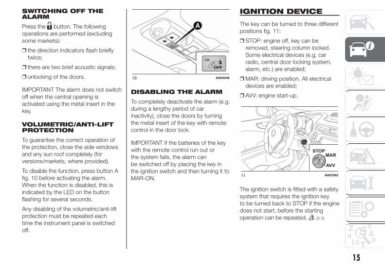
SWITCHING OFF THEALARM
Press the button. The following
operations are performed (excluding
some markets):
❒ the direction indicators flash briefly
twice;
❒ there are two brief acoustic signals;
❒ unlocking of the doors.
IMPORTANT The alarm does not switch
off when the central opening is
activated using the metal insert in the
key.
VOLUMETRIC/ANTI-LIFTPROTECTION
To guarantee the correct operation of
the protection, close the side windows
and any sun roof completely (for
versions/markets, where provided).
To disable the function, press button A
fig. 10 before activating the alarm.
When the function is disabled, this is
indicated by the LED on the button
flashing for several seconds.
Any disabling of the volumetric/anti-lift
protection must be repeated each
time the instrument panel is switched
off.
DISABLING THE ALARM
To completely deactivate the alarm (e.g.
during a lengthy period of car
inactivity), close the doors by turning
the metal insert of the key with remote
control in the door lock.
IMPORTANT If the batteries of the key
with the remote control run out or
the system fails, the alarm can
be switched off by placing the key in
the ignition switch and then turning it to
MAR-ON.
IGNITION DEVICE
The key can be turned to three different
positions fig. 11:
❒ STOP: engine off, key can be
removed, steering column locked.
Some electrical devices (e.g. car
radio, central door locking system,
alarm, etc.) are enabled;
❒ MAR: driving position. All electrical
devices are enabled;
❒ AVV: engine start-up.
The ignition switch is fitted with a safety
system that requires the ignition key
to be turned back to STOP if the engine
does not start, before the starting
operation can be repeated. 2) 3)
10 A0K0548
11 A0K0362
15
STEERING LOCK
Engagement
When the key is at STOP, remove the
key and turn the steering wheel until
it locks.
Disengagement
Move the steering wheel slightly and
turn the ignition key to MAR-ON. 4) 5)
WARNING
2) If the ignition device has been
tampered with (e.g. an attempted
theft), have it checked over by a
Alfa Romeo Dealership as soon as
possible.
3) When getting out of the car,
always remove the key to prevent
someone from accidentally
activating the controls.
Remember to engage the
handbrake. Engage 1st gear if the
car is parked uphill or reverse if
the car is parked downhill. Never
leave children unattended in the
car.
4) It is absolutely forbidden to carry
out any after-market operation
involving steering system or
steering column modifications
(e.g.: installation of anti-theft
device). This could badly affect
performance and safety,
invalidate the warranty and also
result in the non-compliance
of the car with approval
requirements.
5) Never remove the key while the
car is moving. The steering wheel
will lock as soon as it is turned.
This holds true for cars being
towed as well.
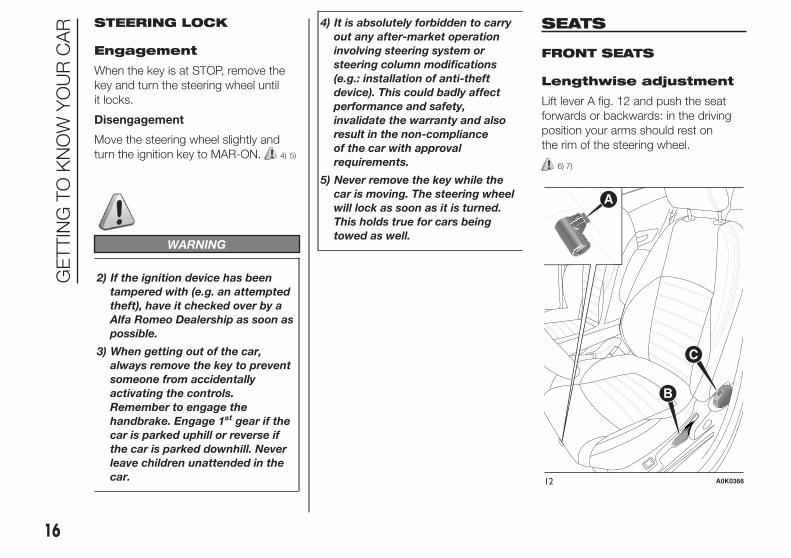
SEATS
FRONT SEATS
Lengthwise adjustment
Lift lever A fig. 12 and push the seat
forwards or backwards: in the driving
position your arms should rest on
the rim of the steering wheel.
6) 7)
12 A0K0366
16
GE
TTIN
GTO
KN
OW
YO
UR
CA
R

Height adjustment
(for versions/markets, where provided)
Move lever B fig. 12 up or down until
the required height is reached.
IMPORTANT Carry out the adjustment
whilst seated in the driver's seat.
Backrest angleadjustment
Turn knob C fig. 12 until the required
position is reached.
8)
Electric seat heating(for versions/markets, where provided)
With the key turned to MAR-ON, press
button A fig. 13 to switch the function
on/off.
When the function is enabled, the LED
on the button switches on.
Electric lumbaradjustment(for versions/markets, where provided)
With the key turned to MAR-ON, press
button B fig. 13 to switch the function
on/off.
When the function is enabled, the LED
on the button switches on.
FRONT SEATS WITHELECTRIC ADJUSTMENT(for versions/markets, where provided)
The controls for seat adjustment are fig.
14:
Multifunction control A:
❒ seat height adjustment (vertical seat
movement);
❒ lengthwise seat movement;
B: Backrest angle and lumbar
adjustment;
C: Driver's side seat position memory
buttons.
IMPORTANT Electric adjustment is only
possible with the ignition key turned
to MAR-ON and for approximately
1 minute after turning it to STOP. The
seat can be moved after opening the
door for about 3 minutes, or until the
door is closed.
Memorising driver’sseat positions
Buttons C allow three different driver’s
seat positions to be memorised and
recalled.
Memorisation and recall are possible
with the ignition key in MAR-ON
position and for 3 minutes after opening
the driver's side door or until the door
is closed, even when the ignition key
is to the STOP position.
The performed position memorisation is
confirmed by a beep.
To memorise a seat position, adjust it
with the various controls, then press the
button where you want to memorise
the position for several seconds.
When a new seat position is
memorised, the previously memorised
position on the same button is
automatically overwritten.13 A0K0213
14 A0K0214
17

Recalling a memorised position is also
possible for about 3 minutes after
the doors are opened and about 1
minute after the ignition key is turned to
the STOP position.
To recall a memorised position, press
the relevant button briefly.
SEAT HEATING(for versions/markets, where provided)
With the ignition key at MAR-ON,
turn ring nut A fig. 15 to switch the
function on/off.
Heating can be set to 3 different levels
(0 = seat heating off).
WARNING
6) All adjustments must be made
solely with the car stationary.
7) After releasing the adjustment
lever, always check that the seat
is locked on the guides by trying
to move it back and forth. Failure
to lock the seat in place could
result in its unexpected
movement and the driver losing
control of the car.
8) For maximum protection keep the
backrest upright, lean back into it
and make sure that the seat belt
fits closely across the chest and
pelvis.
HEAD RESTRAINTS
FRONT
These are height-adjustable and lock
into the desired position automatically.
For the height adjustments proceed
as follows: 9)
❒ upwards adjustment: raise the head
restraint until it clicks into place;
❒ downwards adjustment: press button
A fig. 16 and lower the head restraint.
Proceed as follows to remove the head
restraints:
❒ raise the head restraints to their
maximum height;
❒ press buttons A and B fig. 16, then
remove the head restraints by pulling
them upwards.
15 A0K0215
16 A0K0624
18
GE
TTIN
GTO
KN
OW
YO
UR
CA
R

“Anti-Whiplash” device
The head restraints are equipped with
an “Anti-Whiplash” device, which
reduces the distance between head
and head restraint in the event of a rear
impact, thus mitigating the “whiplash”
effect.
The head restraint may move when the
backrest is pressed by the occupant's
torso or hand: this behaviour is caused
by the system and should not be
considered a malfunction.
REAR
Two height-adjustable head restraints
are provided for the back seats (for the
adjustment see the previous
paragraph).
On some versions a head restraint is
also provided for the central seat.
Proceed as follows to remove the head
restraints:
❒ raise the head restraints to their
maximum height;
❒ press buttons A and B fig. 17, then
remove the head restraints by pulling
them upwards.
WARNING
9) The head restraints must be
adjusted so that the head, rather
than the neck, rests on them. Only
in this case they can protect your
head correctly.
STEERING WHEEL
It can be adjusted axially and vertically.
To adjust, release the lever by pushing it
forwards (position 1 fig. 18) and adjust
the steering wheel. Having made the
adjustment, lock lever A by pulling
it towards the steering wheel (position
2). 10) 11)
NOTE The "Quadrifoglio Verde"
versions are equipped with sports
configuration steering wheel.
17 A0K0625
18 A0K0700
19

WARNING
10) Any adjustment of the steering
wheel position must be carried
out only with the car stationary
and the engine turned off.
11) It is absolutely forbidden to carry
out any after-market operation
involving steering system or
steering column modifications
(e.g. installation of anti-theft
device) that could adversely affect
performance and safety,
invalidate the warranty and also
result in the car not meeting
type-approval requirements.
REAR VIEWMIRRORS
INTERNAL MIRROR
The rear view mirror has two different
positions: normal or anti-glare.
Adjustment
The mirror must be adjusted starting
from the normal position, with the lever
A fig. 19 towards the windscreen
(daytime use).
To prevent dazzling effects due to
following cars, the mirror can be moved
into the anti-glare position by moving
the lever A towards the back of the car.
Electrochromic interiormirror(for versions/markets, where provided)
The electrochromic rear view mirror
fig. 20 comes with an adjustment
device to automatically prevent dazzling
effects due to following cars. This
function is set as default.
When reverse gear is engaged, the
mirror is automatically set for daytime
use.
When reverse gear is engaged, the
mirror is automatically set for daytime
use.
19 A0K0549
20 A0K0550
20
GE
TTIN
GTO
KN
OW
YO
UR
CA
R

DOOR MIRRORS
Electric adjustment
The mirrors can only be adjusted/folded
with the ignition in the MAR position.
Select the desired mirror using device A
fig. 21 12):
❒ device in position 1: left mirror
selected
❒ device in position 2: right mirror
selected.
To adjust the selected mirror, press
button B in the four directions shown
by the arrows.
IMPORTANT Once adjustment is
complete, rotate device A to position 0
to prevent accidental movements.
Electric mirror folding(for versions/markets, where provided)
To fold the mirrors, press button C
fig. 21. Press the button again to
restore the mirrors to the driving
position.
Mirror manual folding
If necessary, fold the mirrors, moving
them from position 1 to position 2
fig. 22.
IMPORTANT When driving the mirrors
must always be in position 1.
WARNING
12) As the driver's door mirror is
curved, it may slightly alter the
perception of distance.
21 A0K0551
22 A0K0552
21

CLIMATE CONTROL
SIDE AIR DIFFUSERS
A fig. 23 - Adjustable and directable
side air diffusers:
❒ use device B to adjust the diffuser to
the desired position;
❒ turn wheel C left to adjust the air flow.
D - Fixed side air diffuser.
CENTRAL AIRDIFFUSERS
Use device A fig. 24 to adjust the
diffusers to the desired position.
Turn wheels B downwards to adjust the
air flow.
UPPER AIR DIFFUSERS
A fig. 25 - Upper adjustable air
diffusers. Turn wheels B to the right to
adjust the air flow.
C - Fixed upper air diffuser.
REAR AIR DIFFUSER(for versions/markets, where provided)
Use device A fig. 26 to adjust the
diffuser to the desired position.
Turn wheel B to the right to adjust the
air flow:
= Completely closed
= Completely open23 A0K0603
24 A0K0604
25 A0K0605
26 A0K0606
22
GE
TTIN
GTO
KN
OW
YO
UR
CA
R

CLIMATIC COMFORT
DIFFUSERS
1. Fixed upper diffuser – 2. Fixed upper diffusers – 3. Fixed side vents – 4. Adjustable side vents – 5. Adjustable centre vents – 6. Lower diffusers forrear seats – 7. Adjustable vent for rear seats (for versions/markets, where provided) – 8. Lower diffusers for front seats
27 A0K0602
23

MANUAL CLIMATECONTROL
.
CONTROLS
A - Air temperature adjustment knob:
❒ blue section = cold air
❒ red section = hot air
B - climate control compressor on/off
button;
C - fan activation/adjustment knob:
❒ 0 = fan off
❒ 1-2-3-4-5-6 = fan speed
D - heated rear window on/off button;
E - air distribution knob:
❒ various selections are possible
❒ quick demisting of windscreen and
side windows
F - air recirculation on/off button
28 A0K0553
24
GE
TTIN
GTO
KN
OW
YO
UR
CA
R

CLIMATE CONTROL(cooling)
To cool, proceed as follows:
❒ turn knob A to the blue section;
❒ press button F to turn internal air
recirculation on (circular LED around
the button on);
❒ turn knob E to ;
❒ press button B to turn the climate
control system on and turn knob C to
at least 1 (1st speed); for faster
action, turn knob C to 6 (maximum
fan speed).
Adjusting cooling
Proceed as follows:
❒ turn knob A to the right to increase
the temperature;
❒ press button F to turn internal air
recirculation off (circular LED around
the button off);
❒ turn knob C to reduce the fan speed.
PASSENGERCOMPARTMENT HEATING
For rapid heating, proceed as follows:
❒ turn knob A to the red section;
❒ press button F to turn on the internal
air recirculation system;
❒ turn knob E to ;
❒ turn knob C to 6 (maximum fan
speed).
Then use the controls to maintain the
desired comfort conditions and press
button F to turn internal air recirculation
off (circular LED around the button off)
and prevent misting.
IMPORTANT When the engine is cold, it
takes a few minutes to obtain fast
heating.
AUTOMATICDEMISTING/DEFROSTING(MAX-DEF function)
This function activates automatic
demisting/defrosting of: front windows
(windscreen and side windows), heated
nozzles, heated exterior rear view
mirrors.
To activate the function, turn knob E to
the “Defrosting” symbol identified by
the symbol.
The manual climate control system will
automatically set itself to the following
configuration:
❒ the demisting symbol will turn
from red to orange (to indicate that
the function has been activated);
❒ the heated rear window (and all
defrosting devices in the car) will be
turned on. The circular LED around
the button will light up to indicate
that the function has been activated;
❒ the air flow will go to maximum
speed (6th);
❒ air circulation will be opened, if it was
closed (the circular LED around the
corresponding button will be off);
❒ air mixing will go to “maximum heat”;
❒ the additional electric heater (for
versions/markets, where provided)
will be turned on;
❒ the compressor will be activated (the
circular LED will switch on to indicate
that the AC function is on).
Window demisting
The climate control system is very
useful in preventing the windows from
misting up in the event of high levels
of humidity.
In the event of considerable outside
moisture and/or rain and/or
considerable differences in temperature
inside and outside the passenger
compartment, proceed as follows to
demist the windows:
❒ turn knob A to the red section;
25

❒ press button F to turn internal air
recirculation off (circular LED around
the button off);
❒ turn knob E to with the possibility
of moving it to position (B) if
demisting does not occur;
❒ turn knob C to the 2nd speed.
HEATED REAR WINDOWDEMISTING/DEFROSTING
Press button D ( ) to activate/
deactivate the function. The function is
automatically deactivated after 20
minutes.
For versions/markets where provided,
press the button to activate
demisting/defrosting of exterior rear
view mirrors and heated nozzles (for
versions/markets, where provided).
IMPORTANT Do not affix stickers to the
inside of the heated rear window over
the heating filaments, to avoid damage
that might cause them to stop working
properly.
INTERNAL AIRRECIRCULATION
Press button F ( ) so that the LED
around the button turns on. It is
advisable to switch internal air
recirculation on while standing in traffic
or in tunnels to prevent the introduction
of polluted air.
Do not use the function for a long time,
particularly if there are many
passengers on board, to prevent the
windows from misting up.
IMPORTANT Internal air recirculation
makes it possible to reach the required
heating or cooling conditions more
quickly depending on the mode
selected. Do not use the air
recirculation function on rainy/cold days
as it would considerably increase the
possibility of the windows misting.
SETTING THE AIRDISTRIBUTION
Turn knob E to manually select one of
the four possible air distribution settings
in the passenger compartment:
Air flow to the windscreen and front
side window diffusers to demist/
defrost them.
Air flow to the front/rear footwell
diffusers. This air distribution allows
the passenger compartment to
be warmed up quickly.
Air flow distribution between front
and rear diffusers, centre/side
dashboard diffusers, rear diffuser
and windscreen and front side
window demisting/defrosting
diffusers.
Air flow distribution to centre/side
dashboard diffusers (passenger's
body).
There are also another 4 positions (see
diagram below fig. 29):
29 A0K0554
26
GE
TTIN
GTO
KN
OW
YO
UR
CA
R

Position A: Air flow distribution
between centre/side dashboard
vents, rear diffuser and windscreen
and front side window demisting/
defrosting diffusers. This
distribution setting ventilates the
passenger compartment well and
prevents the windows from misting
up.
Position B: Air flow distributed
between footwell diffusers and
windscreen and front side window
defrosting/demisting diffusers.
This distribution setting allows the
passenger compartment to warm
up efficiently and prevents the
windows from misting up.
Position C: Air flow distribution
between footwell diffusers (hotter
air) and centre/side dashboard
diffusers and rear diffuser (cooler
air).
Position D: Automatic
demisting/defrosting activation
(see description in previous
pages).
START&STOP
Manual climate control
If the Start&Stop function is activated
(engine off when the car speed is
0 km/h), the system keeps the air flow
selected by the user.
In these conditions, the compartment
cooling and heating cannot be
guaranteed, as the compressor stops
with the engine coolant pump.
The Start&Stop function can be
deactivated to enhance the operation of
the climate control system by pressing
the dedicated button on the
dashboard.
SERVICINGMAINTENANCE
In winter, the climate control system
must be turned on at least once a
month for about 10 minutes.
Have the system inspected at an Alfa
Romeo Dealership before the summer.
27

AUTOMATIC DUALZONE CLIMATECONTROL
(for versions/markets, where provided)
.
CONTROLS
A - driver side temperature adjustment
knob;
B - internal air recirculation on/off
button;
C - climate control system compressor
on/off button;
D - heated rear window on/off button;
E - climate control on/off button;
F - fan speed adjustment knob;
G - Fan speed indicator LED;
H - air distribution selection buttons;
30 A0K0555
28
GE
TTIN
GTO
KN
OW
YO
UR
CA
R

I - MAX-DEF function (rapid defrosting/
demisting of front windows), heated
rear window and heated exterior mirrors
(for versions/markets, where provided)
activation button;
L - passenger side temperature
adjustment knob;
M - MONO function activation button
(alignment of set temperatures)
driver/passenger side;
N - AUTO function activation button
(automatic operation).
DESCRIPTION
The automatic dual zone climate control
system regulates the air temperatures
in the passenger compartment in two
areas: driver side and passenger side.
The system maintains comfort inside
the passenger compartment and
compensates for possible variations in
external climate conditions.
Note The reference temperature is
22°C for optimal comfort management.
The automatically controlled
parameters and functions are:
❒ air temperature at the driver's/front
passenger side vents;
❒ air distribution at the driver's/front
passenger side vents;
❒ fan speed (continuous variation of the
air flow);
❒ compressor engagement (for
cooling/dehumidifying the air);
❒ air recirculation.
All these functions can be adjusted
manually by operating the system and
selecting one or more functions and
modifying their parameters. Automatic
control of the manually changed
functions will be suspended: the
system will only override the settings for
safety reasons.
Manual selections always have higher
priority than automatic settings and are
stored until the AUTO button is
pressed, except for cases in which the
system intervenes for safety reasons.
You can adjust one function manually
without affecting the automatic control
of the others. The amount of air
introduced into the passenger
compartment is not affected by vehicle
speed; it is electronically controlled
by a fan.
The temperature of the air sent is
always automatically controlled
according to the temperature set on the
display (except for when the system is
off or in certain conditions when the
compressor is not running). 2)
The system allows the following to be
set or adjusted manually:
❒ driver's/passenger side air
temperature;
❒ fan speed (continuous variation);
❒ air distribution pattern with 7
positions;
❒ compressor enabling;
❒ rapid defrosting/demisting function;
❒ air recirculation;
❒ heated rear window;
❒ system deactivation.
CLIMATE CONTROLSYSTEM OPERATINGMODES
The climate control system can be
activated in different ways: it is
advisable to press the AUTO button
and turn the knobs to set the desired
temperatures.
In this way the system operates
completely automatically to adjust the
temperature, quantity and distribution
of the air introduced into the passenger
compartment. It also manages the air
recirculation system and the activation
of the air conditioning compressor.
29

During automatic operation, you can
change the set temperatures, air
distribution and fan speed at any time
by using the relevant buttons or knobs:
the system will automatically change
the settings to adjust to the new
requirements.
During fully automatic operation
(AUTO), the word AUTO will disappear
if the air distribution and/or flow rate
and/or engagement of the compressor
and/or recirculation settings are
changed.
During fully automatic operation (FULL
AUTO), the word FULL will disappear
if the air distribution and/or flow rate
and/or activation of the compressor
and/or recirculation settings are
changed.
In this way the climate control system
will continue to automatically manage
all functions except for those that have
been manually adjusted. The fan speed
is the same in all the zones of the
passenger compartment.
ADJUSTING THE AIRTEMPERATURE
Turn knob A or L to the right or left to
adjust the air temperature: knob A
for the front left area, knob L for the
front right area of the passenger
compartment. The set temperatures are
shown on the displays.
Press the MONO button to align the air
temperature between the two areas.
Turn knob L to return to the separate
management of air temperatures in the
two areas.
Turn the knobs fully right or left to
engage HI (maximum heating) or LO
(maximum cooling) respectively. To
deactivate these functions, turn the
temperature knob to the desired
temperature.
SETTING THE AIRDISTRIBUTION
By pressing the buttons ( / / ), it
is possible to set one of the 7 possible
air distributions manually:
Air flow to the windscreen and
front side window diffusers to
demist/defrost them.
Air flow at central and side
dashboard vents to ventilate the
chest and the face during the hot
season.
Air flow to the front and rear
footwell diffusers. This air
distribution setting heats the
passenger compartment most
quickly, giving a prompt sensation
of warmth.
Air flow distributed between
footwell vents (hotter air) and
central and side dashboard
vents (cooler air). This
distribution setting is useful in
spring and autumn on sunny
days.
Air flow distributed between
footwell diffusers and
windscreen and front side
window defrosting/demisting
diffusers. This distribution
setting allows the passenger
compartment to warm up
efficiently and prevents the
windows from misting up.
Air flow distribution between
windscreen demisting/
defrosting diffusers and side
and central dashboard vents.
This allows air to be sent to
the windscreen in conditions of
strong sunlight.
Air flow distribution to all
vents on the car.
30
GE
TTIN
GTO
KN
OW
YO
UR
CA
R

In AUTO mode, the climate control
system automatically manages air
distribution (the LEDs on buttons H are
off). When set manually, the air
distribution is shown by the LEDs on
the selected buttons.
In combined function mode the relevant
function is enabled simultaneously
with those already set by pressing the
corresponding button. If a button
whose function is already active is
pressed, its operation is cancelled and
the corresponding LED switches off.
To restore automatic control of the
air distribution after a manual selection,
press the AUTO button.
ADJUSTING THE FANSPEED
Turn knob F to increase/decrease the
fan speed. The speed is indicated
by the LEDs G on knob F switching on.
❒ maximum fan speed = all LEDs lit;
❒ minimum fan speed = one LED lit.
The fan can only be excluded if the
climate control compressor has been
switched off by pressing button C.
IMPORTANT To restore automatic
control of the fan speed after a manual
adjustment, press the AUTO button.
AUTO BUTTON
By pressing the AUTO button (LED on
button lit) the climate control system
automatically adjusts the following
settings in the corresponding zones:
❒ quantity and distribution of the air
introduced into the passenger
compartment;
❒ climate control compressor;
❒ air recirculation
❒ cancelling any previous manual
settings.
This is indicated by the LED on the
AUTO button switching on.
By manually adjusting at least one of
the functions automatically managed by
the system (air recirculation, air
distribution, fan speed or switching off
the air conditioner compressor), the
LED will switch off, indicating that the
climate control system is no longer
automatically controlling all the
functions.
IMPORTANT Should the system no
longer be able to guarantee the
required temperature set in various
passenger compartment zones, the set
temperature value will flash for a few
seconds.
To restore automatic system control
after one or more manual adjustments,
press the AUTO button.
MONO BUTTON
Press the MONO button (LED on
button lit) to align the passenger side air
temperature with that of the driver
side.
This function makes temperature
regulation easier when the driver is
travelling alone.
Turn knob L to set the passenger side
temperature and return to separate
air temperature management.
AIR RECIRCULATION ANDENABLEMENT OF AQSFUNCTION (Air QualitySystem)(for versions/markets, where provided)
The air recirculation is managed
according to the following operating
logics:
❒ automatic activation: text A on button
B lit;
❒ forced activation (inside air
recirculation always on): indicated by
the LED on button and text A
off;
31

❒ forced deactivation (air recirculation
always off, air drawn in from the
outside): indicated by the LED on
buttons switching off and text A
on button B off.
Forced activation/deactivation can be
selected by pressing button .
When the button is pressed (button
E off), the climate control system
automatically activates internal air
recirculation (LED on button A
on). It is still possible to activate outside
air recirculation (LED on the button off)
and vice versa, by pressing button
.
The AQS (Air Quality System) function
(for versions/markets, where provided)
cannot be activated when the button
is pressed (LED on button E off).
AQS (Air Quality System)function activation(for versions/markets, where provided)
The AQS function automatically
activates internal air recirculation when
the outside air is polluted (e.g. in traffic
queues and tunnels).
IMPORTANT With the AQS function
active, after a preset time interval of the
internal air recirculation system
functioning, the climate control system
enables the intake of outside air for
approximately one minute to change
the air in the passenger compartment.
This takes place regardless of the
pollution level of the outside air.
IMPORTANT The engagement of the
recirculation system makes it possible
to reach the required heating/cooling
conditions faster. It is, however,
inadvisable to use it on rainy/cold days
as it would considerably increase the
possibility of the windows misting
up inside (especially if the climate
control system is off). When the outside
temperature is low, recirculation is
forced off (air drawn in from the outside)
to prevent the windows from misting
up.
In automatic operation, recirculation is
managed automatically by the system
according to outside environmental
conditions.
IMPORTANT It is advisable not to use
the air recirculation function when
the outside temperature is low to
prevent the windows from rapidly
misting up.
CLIMATE CONTROLCOMPRESSOR
Press button C to activate/deactivate
the compressor (activation is indicated
by the lit LED on the button). The
system remembers that the
compressor has been switched off,
even after the engine has stopped.
When the compressor is switched off
the system deactivates air recirculation
to prevent the windows from misting
up and deactivates the AQS function
(for versions/markets, where provided).
In this case, although the climate
control system is capable of
maintaining the required temperature,
the AUTO LED switches off. The
temperatures will flash for a few
seconds if the required temperature
cannot be maintained.
To restore automatic control of
compressor engagement, press again
button C or the AUTO button.
With compressor off:
❒ if the outside temperature is higher
than the set one, the system will
not be able to satisfy the request.
The temperature values will then flash
on the display for a few seconds to
indicate this;
❒ the fan speed can be reset manually.
32
GE
TTIN
GTO
KN
OW
YO
UR
CA
R

With the compressor on and the engine
running, manual ventilation cannot be
lower than the minimum speed (only
one LED lit).
IMPORTANT With the compressor off,
air cannot be introduced to the
passenger compartment with
a temperature lower than the outside
temperature. Moreover, under certain
environmental conditions, windows
could mist up rapidly since the air is not
dehumidified.
RAPID WINDOWDEMISTING/DEFROSTING(MAX-DEF function)
Press the button to activate (LED
on button on) the windscreen and side
windows demisting/defrosting function.
The climate control system carries out
the following operations:
❒ switches on the air conditioning
compressor when climatic conditions
are suitable;
❒ deactivates air recirculation;
❒ sets maximum air temperature (HI) in
both zones;
❒ sets fan speed according to the
engine coolant temperature;
❒ directs air flow to windscreen and
front side windows diffusers;
❒ activates the heated rear window.
❒ displays the fan speed (LED G lit).
IMPORTANT The MAX-DEF function
remains on for about 3 minutes from
when the engine coolant reaches the
appropriate temperature.
When the function is activated, the LED
on the AUTO button switches off.
With the function activated the only
possible manual adjustments are
adjusting the fan speed and turning the
heated rear window off.
When the B, C, or AUTO buttons
are pressed, the climate control system
will turn the MAX-DEF off.
HEATED REAR WINDOWDEMISTING/DEFROSTING
Press the button to activate (LED
on button on) heated rear window
demisting/defrosting.
This function switches off automatically
after about 20 minutes or when the
engine is turned off. It is not switched
on automatically the next time the
engine is started.
For versions/markets where provided,
press the button to activate
demisting/defrosting of exterior rear
view mirrors and heated nozzles (for
versions/markets, where provided).
IMPORTANT Do not affix stickers to the
inside of the heated rear window over
the heating filaments, to avoid damage
that might cause them to stop working
properly.
Thermal comfortwindscreen(for versions/markets, where provided)
Some versions feature a thermal
comfort windscreen which, with the car
exposed to the sun, reduces the
temperature in the passenger
compartment relative to the outside
temperature, thus ensuring greater
comfort.
Humidity sensor(for versions/markets, where provided)
The humidity sensor helps to prevent
the windows from misting up. For
full functionality, it is advisable to
activate the AUTO function (LED N on).
When the outside temperature is low,
the system could automatically turn the
compressor on and turn air recirculation
off for safer driving.
33

SWITCHING OFF/ON THECLIMATE CONTROLSYSTEM
Switching off theclimate control system
Press the button (LED on button off).
With climate control off:
❒ air recirculation is on, thus isolating
the passenger compartment from
the outside;
❒ the compressor is off;
❒ the fan is off;
❒ the heated rear window can be
switched on or off;
❒ the AQS (Air Quality System) function
(for versions/markets, where
provided) cannot be activated.
IMPORTANT The climate control
system control unit stores the
temperatures set before the system
was switched off and restores them
when any button of the system is
pressed (except for button D).
Switching on the climatecontrol system
To switch on the climate control system
in fully automatic mode press the AUTO
button.
START&STOP
Automatic ClimateControl
The dual zone automatic climate control
manages the Start&Stop function
(engine off when the car speed is zero)
to guarantee a suitable comfort inside
the car.
Specifically, the Start&Stop function is
turned off when the weather is
particularly hot or cold to guarantee an
adequate level of comfort inside the
passenger compartment; therefore, the
engine will not be stopped during
these transient conditions, even if the
speed is zero.
When the Start&Stop function is active
(engine off at zero car speed), the
climate control system will request
restarting of the engine if the inside
temperature conditions rapidly
deteriorate (or if the user requests
maximum cooling – LO – or quick
demisting – MAX DEF).
With the Start&Stop function on (engine
off at zero speed), air flow is reduced
to the minimum to maintain comfort
conditions inside the passenger
compartment as long as possible when
the system is in AUTO mode (LED N
on).
The climate control system control unit
attempts to manage the discomfort
caused by the engine stopping
(compressor and engine coolant pump
off) but operation of the climate control
system can be enhanced by turning
the Start&Stop off by pressing the
dedicated button on the dashboard.
Note In particularly severe climate
conditions it is recommended to limit
the use of the Start&Stop function
to prevent the compressor from
continuously switching on and off, with
consequent rapid misting of the
windows and accumulation of humidity
with unpleasant smells in the passenger
compartment.
Note When the Start&Stop function is
on (engine off and vehicle speed zero),
the automatic recirculation
management is turned off always taking
air in from outside, to reduce the
probability of window misting up (as the
compressor is off).
34
GE
TTIN
GTO
KN
OW
YO
UR
CA
R

ADDITIONAL HEATER(for versions/markets, where provided)
This allows the passenger
compartment to be heated more
quickly in cold weather conditions. The
additional heater turns off automatically
after the required comfort conditions
are achieved.
Automatic dual zoneclimate control system(for versions/markets, where provided)
The additional heater activates
automatically depending on the
environmental conditions and with
engine started.
Manual climate controlsystem
The additional heater activates
automatically when knob A is turned to
the end of the red section and the fan
is set to at least 1st speed.
IMPORTANT The heater only works if
the outside temperature and engine
coolant temperature are low. The heater
will not activate if the battery voltage is
too low.
IMPORTANT
2) The climate control system
detects the passenger
compartment temperature with a
mean radiant temperature sensor
fitted in a cover under the internal
rear view mirror. Obstructing the
field of view of this sensor with
any object could cause the
climate control system to operate
with less than optimal efficiency
.
EXTERNAL LIGHTS
IN BRIEF
The left stalk fig. 31 operates most of
the external lights. The external
lights can only be switched on when
the ignition key is at MAR-ON.
The instrument panel and the
dashboard and central tunnel
controls will light up together with the
external lights.
DAYTIME RUNNINGLIGHTS (DRL)“Daytime Running Lights”
With the ignition key at MAR-ON and
ring nut A fig. 31 turned to , the
daytime running lights switch on. The
other lights and interior lighting stay off.
31 A0K0556
35

IMPORTANT The daytime running lights
are an alternative to the dipped beam
headlights for driving during the
daytime in countries where it is
compulsory to have lights on during the
day; where it is not compulsory, the
use of daytime running lights is
permitted.
IMPORTANT Daytime running lights
cannot replace dipped beam headlights
when driving at night or through
tunnels. The use of daytime running
lights is governed by the Highway Code
of the country in which you are driving.
Comply with legal requirements.
SIDE LIGHTS/DIPPEDBEAM HEADLIGHTS
With the ignition key turned to
MAR-ON, turn ring nut A fig. 31 to .
The daytime running lights are switched
off and the side lights and dipped
beam headlights are switched on. The
warning light switches on in the
instrument panel.
PARKING LIGHTS
These lights can only be switched on
with ignition key at STOP or removed,
by moving ring nut A fig. 31 first to
position and then to position .
The warning light switches on
in the instrument panel.
AUTOMATIC LIGHTINGCONTROL (AUTOLIGHT)(Dusk sensor)(for versions/markets, where provided)
This infrared LED sensor, combined
with the rain sensor and located on the
windscreen, detects the variations in
outside brightness depending on the
light sensitivity set with the Setup
Menu: the greater the sensitivity, the
less external light is required to activate
the external lights.
Activation
The dusk sensor activates when ring
nut A fig. 31 is turned to . In this
way the side lights and dipped beam
headlights are activated automatically
according to the external lighting
conditions.
IMPORTANT The sensor is unable to
detect the presence of fog. Therefore
under these circumstances, these lights
must be turned on manually.
When the lights are turned on by the
sensor, the fog lights (for versions/
markets, where provided) and the rear
fog lights may be turned on.
When the lights are automatically
switched off, the front and rear fog
lights (if activated) are also switched off.
The next time the lights are switched
on automatically, the fog lights must be
reactivated manually (if required).
With the sensor active, it is possible to
flash the headlights but the main beam
headlights cannot be switched on. To
activate these lights, turn the ring nut A
to and activate the fixed dipped
beam headlights.
When the lights have been activated
automatically and are then switched off
by the sensor, the dipped beam
headlights are switched off first,
followed by the side lights a few
seconds later.
If the sensor is activated but is
malfunctioning, the side lights and
dipped beam headlights are switched
on irrespective of the outside light
level and the sensor failure is indicated
on the display.
It is also possible to deactivate the
sensor and switch on the side lights
and dipped beam headlights.
36
GE
TTIN
GTO
KN
OW
YO
UR
CA
R

MAIN BEAM HEADLIGHTS
To activate the main beam headlights,
with ring nut A fig. 31 at , pull the
stalk towards the steering wheel
beyond the end of travel position. The
warning light switches on in the
instrument panel.
When the stalk is pulled towards the
steering wheel again, beyond the end
of travel position, the main beam
headlights deactivate, the dipped beam
headlights reactivate and the
warning light switches off.
It is not possible to switch on the main
beam headlights constantly if automatic
light control is active.
FLASHING
To do this, pull the stalk towards the
steering wheel (unstable position)
regardless of the position of ring nut A
fig. 31. The warning light switches
on in the instrument panel.
REAR FOG LIGHTS
For the activation and deactivation of
the rear fog lights, refer to the
"Controls" section.
DIRECTION INDICATORS
Bring the stalk to the (stable) position:
❒ upwards: activates right direction
indicator;
❒ downwards: activates left direction
indicator.
Warning light or will blink on the
instrument panel.
The direction indicators are switched off
automatically when the steering wheel
is straightened.
"Lane change" function
If you wish to signal a lane change,
place the left stalk in the unstable
position for less than half a second. The
direction indicator on the side selected
will flash five times and then switch
off automatically.
“FOLLOW ME HOME”DEVICE
This device allows you to illuminate the
area in front of the car for a certain
amount of time.
Activation
With the key turned to STOP or
removed, pull stalk A towards the
steering wheel within 2 minutes from
when the engine is turned off.
Each time the stalk is moved, the lights
stay on for an extra 30 seconds up to
a maximum of 210 seconds; then
the lights are switched off automatically.
Also, each time the stalk is operated,
the warning light on the
instrument panel switches on. The
display shows the time set for the
function and the corresponding
graphics.
The warning light comes on when the
lever is operated and stays on until
the function is automatically
deactivated. Each movement of the
stalk only increases the amount of time
the lights stay on.
Deactivation
Keep the stalk pulled towards the
steering wheel for more than 2
seconds.
37

EXTERNAL COURTESYLIGHTS
These light up the car and the space in
front of it when the doors are unlocked.
Activation
When the car is parked and the doors
are unlocked by pressing the button
on the remote control (or the luggage
compartment is unlocked by pressing
), the dipped beam headlights, rear
side lights and number plate lights are
activated.
The lights stay on for approximately 25
seconds unless the doors and luggage
compartment are locked again with
the remote control or the doors (or
luggage compartment) are opened and
reclosed. In these cases they switch
off after 5 seconds.
The external courtesy lights can be
enabled/disabled using the Setup Menu
(see the “Menu Items” paragraph in
this chapter).
AFS ADAPTIVE LIGHTS(Adaptive Frontlight System)(for versions/markets, where provided)
This is a system combined with Xenon
headlamps which directs the main
light beam and adapts it to the driving
conditions round bends/when
cornering, continuously and
automatically.
The system directs the light beam to
light up the road in the best way, taking
into account the speed of the car, the
bend/corner angle and the speed of
steering.
The adaptive lights are automatically
activated when the car is started.
To activate/deactivate the lights use the
Setup Menu (see paragraph “Menu
Items” in the “Knowing the instrument
panel” section).
WINDOW CLEANING
IN BRIEF
The right stalk controls screen
wiper/washer operation.
This operates only with the ignition
key turned to MAR.
WINDSCREENWASHER/WIPER
Operation 13) 14)
Ring nut A fig. 32 has the following
positions:
O windscreen wipers off;
intermittent operation (low
speed);
32 A0K0557
38
GE
TTIN
GTO
KN
OW
YO
UR
CA
R

AUTO rain sensor activation (for
versions/markets, where
provided) (the windscreen wipers
adapt the operating speed
automatically to suit the intensity
of the rain)
intermittent operation;
continuous slow operation;
continuous fast operation.
Move the stalk upwards (unstable
position) to limit operation to the time
for which the stalk is held in this
position. When released, the stalk will
return to its default position and the
wiper will be automatically stopped.
"Smart washing"function
Pull the lever towards the steering
wheel (unstable position) to operate the
windscreen washer. Keep the stalk
pulled for more than half a second to
operate the windscreen washer jet and
wiper automatically with a single
movement.
The wiper stops working three strokes
after the stalk is released. A further
stroke after approximately 6 seconds
completes the cycle.
RAIN SENSOR(for versions/markets, where provided)
This is an infrared LED sensor fitted
on the car windscreen fig. 33.
It is able to detect the presence of rain
and consequently manage windscreen
wiping in accordance with the amount
of water on the windscreen.
Activation
The sensor is activated when ring nut A
fig. 32 is turned to “automatic” position
(“AUTO” control): the windscreen wiper
stroke frequency is thus adjusted in
accordance with the amount of water
on the windscreen.
This frequency can vary from no stroke
(no rain - windscreen dry) up to the
2nd constant speed operation (heavy
rain - windscreen wet).
The sensitivity of the rain sensor can be
adjusted through the Setup menu
(see paragraph “Menu Items” in the
“Knowing the instrument panel”
section).
If the engine is stopped with the lever in
“automatic” position, when it is next
started no wiping cycle will take place
even if it is raining. This prevents
accidental activation of the rain sensor
when the engine is started (e.g. when
the windscreen is being washed by
hand or the wipers are stuck to the
windscreen when there is ice).
To restore automatic operation of the
rain sensor, turn the ring nut on the
right stalk A fig. 32 from automatic
position (AUTO) to O position and then
turn A ring nut back to the AUTO
position.
When the rain sensor is reactivated
using any of the manoeuvres described
above, reactivation is indicated by a
single stroke of the windscreen wipers,
regardless of the condition of the
windscreen.
If the sensitivity is changed whilst the
rain sensor is operating, a windscreen
wiper stroke is carried out to confirm
the change.
33 A0K0558
39

In the event of malfunction of the rain
sensor whilst it is active, the
windscreen wiper operates
intermittently at a speed consistent with
the sensitivity setting of the rain sensor,
regardless of whether there is rain on
the glass (sensor failure is indicated on
the display).
The sensor continues to operate and it
is possible to set the windscreen wiper
to continuous mode (1st or 2nd speed).
The failure indication remains for as
long as the sensor is active.
REAR WINDOWWASHER/WIPER(for versions/markets, where provided)
Activation
This operates only with the ignition key
turned to MAR.
Turn ring nut B fig. 32 from position O
to position to operate the rear
window wiper as follows:
❒ in intermittent mode when the
windscreen wiper is not operating;
❒ in synchronous mode (at half the
speed of the windscreen wiper) when
the windscreen wiper is operating;
❒ in continuous mode with reverse gear
engaged and the control active.
With reverse gear engaged and
windscreen wiper on, the rear window
wiper is activated in continuous mode.
Pushing the stalk towards the
dashboard (unstable position) will
activate the rear window washer jet.
Keep the stalk pushed for more than
half a second to activate the rear
window wiper as well. Releasing the
stalk will activate the smart washing
function, as described for the
windscreen wiper.
WARNING
13) Do not use the screen wiper to
remove layers of snow or ice
from the windscreen. In such
conditions, the windscreen wiper
may be subjected to excessive
stress and the motor cut-out
switch, which prevents operation
for a few seconds, may intervene.
If operation is not restored (even
after restarting that car with the
key), contact an Alfa Romeo
Dealership.
14) Do not operate the windscreen
wiper with the blades lifted from
the windscreen.
CRUISE CONTROL
(for versions/markets, where provided)
IN BRIEF
This is an electronically controlled
driving assistance device that allows
the desired car speed to be
maintained, without having to press
the accelerator pedal. This device
can be used at a speed above
30 km/h on long stretches of dry,
straight roads with few variations
(e.g. motorways).
The use of this device on extra-urban
roads with traffic is not therefore
recommended. Do not use it in town.
TURNING THE DEVICEON
Turn ring nut A fig. 34 to ON.
34 A0K0559
40
GE
TTIN
GTO
KN
OW
YO
UR
CA
R
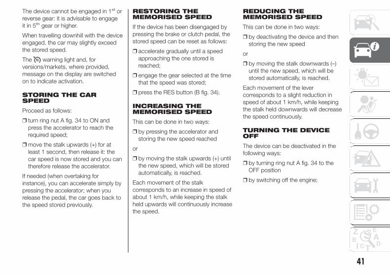
The device cannot be engaged in 1st or
reverse gear: it is advisable to engage
it in 5th gear or higher.
When travelling downhill with the device
engaged, the car may slightly exceed
the stored speed.
The warning light and, for
versions/markets, where provided,
message on the display are switched
on to indicate activation.
STORING THE CARSPEED
Proceed as follows:
❒ turn ring nut A fig. 34 to ON and
press the accelerator to reach the
required speed;
❒ move the stalk upwards (+) for at
least 1 second, then release it: the
car speed is now stored and you can
therefore release the accelerator.
If needed (when overtaking for
instance), you can accelerate simply by
pressing the accelerator; when you
release the pedal, the car goes back to
the speed stored previously.
RESTORING THEMEMORISED SPEED
If the device has been disengaged by
pressing the brake or clutch pedal, the
stored speed can be reset as follows:
❒ accelerate gradually until a speed
approaching the one stored is
reached;
❒ engage the gear selected at the time
that the speed was stored;
❒ press the RES button (B fig. 34).
INCREASING THEMEMORISED SPEED
This can be done in two ways:
❒ by pressing the accelerator and
storing the new speed reached
or
❒ by moving the stalk upwards (+) until
the new speed, which will be stored
automatically, is reached.
Each movement of the stalk
corresponds to an increase in speed of
about 1 km/h, while keeping the stalk
held upwards will continuously increase
the speed.
REDUCING THEMEMORISED SPEED
This can be done in two ways:
❒ by deactivating the device and then
storing the new speed
or
❒ by moving the stalk downwards (–)
until the new speed, which will be
stored automatically, is reached.
Each movement of the lever
corresponds to a slight reduction in
speed of about 1 km/h, while keeping
the stalk held downwards will decrease
the speed continuously.
TURNING THE DEVICEOFF
The device can be deactivated in the
following ways:
❒ by turning ring nut A fig. 34 to the
OFF position
❒ by switching off the engine;
41

❒ by pressing the brake pedal, the
clutch or the accelerator; in this
last case the system is not effectively
deactivated but the system gives
priority to the acceleration request.
The device still remains active,
without the need to press the RES
button to return to the previous
conditions once acceleration
is concluded.
Automatic deactivation
The device deactivates automatically in
the following cases:
❒ if the ABS or ESC systems intervene;
❒ with the car speed below the set
limit;
❒ in the event of system failure.
15) 16)
WARNING
15) When travelling with the device
active, do not move the gear lever
to neutral.
16) In the event of device faults or
failures, turn the ring nut A to
OFF and contact an Alfa Romeo
Dealership.
ROOF LIGHTS
FRONT ROOF LIGHT
Switch A fig. 35 switches the roof lights
on/off.
A switch positions:
❒ central position: lights C and E switch
on/off when the doors are opened/
closed;
❒ pressed to the left (position OFF):
lights C and E are always switched
off;
❒ pressed to the right (position ):
lights C and E are always switched
on.
Lights switch on/off progressively.
Switch B switches light C on/off.
Switch D switches light E on/off.
IMPORTANT Before getting out of the
car, make sure that both switches are in
the central position: when the doors
are closed the lights will switch off
to avoid draining the battery.
In any case, if the switch is left
inadvertently in the permanently on
position, the roof light will turn off
automatically 15 minutes after the
engine stopping.
ROOF LIGHT TIMING
On certain versions, to facilitate getting
in/out of the car at night or in poorly-lit
areas, two timed modes have been
provided.
Timing when getting intothe car
The roof lights switch on according to
the following modes:
❒ for about 10 seconds when the
doors are unlocked;
❒ for about 3 minutes when one of the
doors is opened;
❒ for about 10 seconds when the
doors are closed.
The timed period is interrupted when
the ignition key is turned to MAR.
35 A0K0805
42
GE
TTIN
GTO
KN
OW
YO
UR
CA
R

Timing when getting outof the car
After removing the key from the ignition
switch, the roof lights switch on as
follows:
❒ within 2 minutes of the engine being
switched off for a period of around
10 seconds;
❒ for about 3 minutes when one of the
doors is opened;
❒ for about 10 seconds when one of
the doors is closed.
The timing stops automatically when
the doors are locked.
REAR ROOF LIGHT
Press the cover A fig. 36 to switch the
light on/off.
The light will stay on for a few seconds
after the doors are closed and will
then switch off automatically. The light
switches off in any case when the
ignition key is turned to MAR.
IMPORTANT The light switches off
automatically after a few minutes if a
door is left open. To switch it on again,
open another door or close and reopen
the same door.
COURTESY LIGHTS(for versions/markets, where provided)
Two courtesy roof lights B fig. 37 are
present behind the sun visors.
Lift cover A to turn the lights on.
LUGGAGECOMPARTMENT ROOFLIGHT
This is located on the left side of the
luggage compartment fig. 38.
This switches on automatically when
the luggage compartment is opened
and switches off when it is closed.
The light switches on/off regardless of
the ignition key position.
36 A0K0561
37 A0K0562
38 A0K0563
43

CONTROLS
HAZARD WARNINGLIGHTS
Operation
Press switch A fig. 40 to switch the
lights on/off.
Warning lights and on the
instrument panel switch on and switch
A flashes when the lights are on.
Emergency braking
In the event of emergency braking the
hazard warning lights are lit up
automatically as well as the and
warning lights in the panel.
The lights switch off automatically when
emergency braking ceases.
17)
FOG LIGHTS(for versions/markets, where provided)
Operation
Press button fig. 41 to switch the
lights on/off.
With the lights on, warning light in
the instrument panel switches on.
REAR FOG LIGHTS
Operation
Press button fig. 41 to switch the
lights on/off.
The rear fog lights are only switched on
with the dipped headlights or front
fog lights on.
Press the button again to switch the
lights off, or switch off the dipped
headlights or the front fog lights (for
versions/markets, where provided).
39 A0K0564 40 A0K0622
41 A0K0609
44
GE
TTIN
GTO
KN
OW
YO
UR
CA
R GLOVE COMPARTMENTLIGHT
This light comes on automatically when
the glove compartment is opened
and switches off when it is closed.
The light switches on/off regardless of
the ignition key position.
With the lights on, warning light in
the instrument panel switches on.

CENTRAL LOCKING
Operation
Press the fig. 42 button to lock all
doors at the same time.
Locking takes place irrespective of the
position of the ignition key.
FUEL CUT-OFF SYSTEM
Operation
This intervenes in the case of an impact
causing:
❒ the interruption of the fuel supply with
the engine consequently cutting out;
❒ the automatic unlocking of the doors;
❒ the interior lights being switched on.
The intervention of the system is
indicated by a message shown on the
display.
Carefully check the car for fuel leaks, for
instance in the engine compartment,
under the car or near the tank area.
18)
After a collision, turn the ignition key to
STOP to prevent the battery from
running down.
To restore the correct operation of the
car, proceed as follows:
❒ turn the ignition key to the MAR-ON
position;
❒ activate the right direction indicator;
❒ deactivate the right direction
indicator;
❒ activate the left direction indicator;
❒ deactivate the left direction indicator;
❒ activate the right direction indicator;
❒ deactivate the right direction
indicator;
❒ activate the left direction indicator;
❒ deactivate the left direction indicator;
❒ turn the ignition key to the STOP
position;
❒ turn the ignition key to the MAR-ON
position.
WARNING
17) The use of hazard warning lights
is governed by the Highway Code
of the country you are driving in:
comply with legal requirements.
18) If, after an impact, you smell fuel
or notice leaks from the fuel
system, do not reactivate the
system to avoid the risk of fire.
42 A0K0588
45

INTERIOR FITTINGS
STORAGECOMPARTMENTS
19)
Upper compartment
Operate in the point shown by the
arrow to open the compartment A fig.
43.
Passenger side glovecompartment
Operate handle A fig. 44 to open the
compartment.
When the compartment is opened, a
courtesy light switches on.
There is a document holder inside the
compartment and an eyewear holder
on the rear of the flap.
On some versions the compartments
may be heated/cooled by an air vent
connected to the climate control
system (operate wheel A fig. 45 to
adjust the air flow rate in the lower
compartment).
In versions with dual-zone automatic
climate control system, the glove
compartment is set to the same
temperature as the passenger's side.
FRONT ARMREST(for versions/markets, where provided)
This is located between the front seats.
To bring it to its standard use position,
push it downwards.
The front armrest is equipped with an
inner storage compartment.
To access the compartment, position
the armrest in the standard use
configuration (fully down) and then lift
the cover with lining A fig. 46.
For correct use of the armrest specific
measures must be followed for the
opening of the cover:
❒ it must be opened only with armrest
completely lowered;
❒ to prevent content of the armrest
from falling, the opening of the cover
is inhibited in positions other than
"completely lowered".
43 A0K0565
44 A0K0566
45 A0K0567
46 A0K0568
46
GE
TTIN
GTO
KN
OW
YO
UR
CA
R

NOTE During the armrest tilting stage
(complete tilting upwards or
downwards), make sure the cover with
lining is always closed correctly.
REAR ARMREST(for versions/markets, where provided)
To use armrest A fig. 47, lower it as
shown in the figure.
Two B cup or can holders are obtained
in the armrest. To use these, pull tab
C in the direction shown by the arrow.
A storage compartment is available
inside the armrest; this can be
accessed by raising the flap.
SKI COMPARTMENT(for versions/markets, where provided)
The compartment may be used for
carrying long loads.
To access the compartment, lower the
rear armrest and then press device A
fig. 48 to lower flap B.
POWER SOCKETS
These are located on the central tunnel
fig. 49 and on the left side of the
luggage compartment fig. 50 (for
versions/markets, where provided).
They only operate with the ignition key
at MAR-ON.
If you request the smokers' kit, the
socket on the central tunnel is replaced
with a cigar lighter (see following
paragraph).
47 A0K0569
48 A0K0570
49 A0K0610
50 A0K0571
47
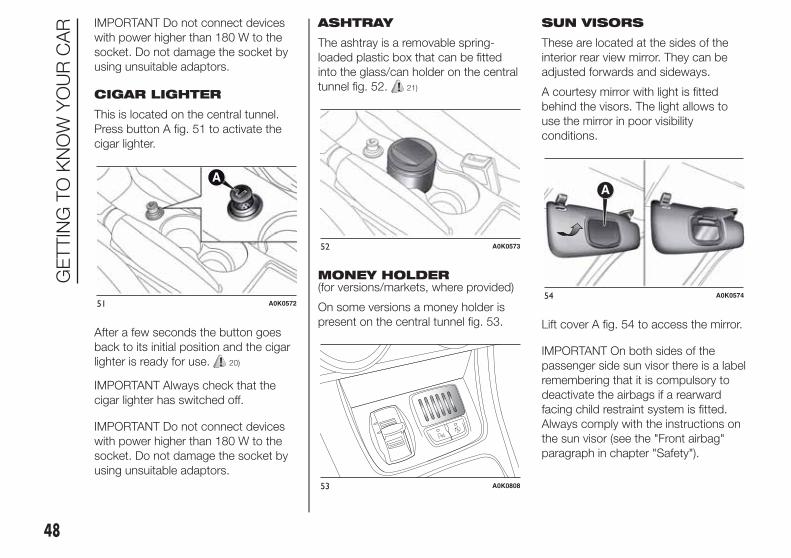
IMPORTANT Do not connect devices
with power higher than 180 W to the
socket. Do not damage the socket by
using unsuitable adaptors.
CIGAR LIGHTER
This is located on the central tunnel.
Press button A fig. 51 to activate the
cigar lighter.
After a few seconds the button goes
back to its initial position and the cigar
lighter is ready for use. 20)
IMPORTANT Always check that the
cigar lighter has switched off.
IMPORTANT Do not connect devices
with power higher than 180 W to the
socket. Do not damage the socket by
using unsuitable adaptors.
ASHTRAY
The ashtray is a removable spring-
loaded plastic box that can be fitted
into the glass/can holder on the central
tunnel fig. 52. 21)
MONEY HOLDER(for versions/markets, where provided)
On some versions a money holder is
present on the central tunnel fig. 53.
SUN VISORS
These are located at the sides of the
interior rear view mirror. They can be
adjusted forwards and sideways.
A courtesy mirror with light is fitted
behind the visors. The light allows to
use the mirror in poor visibility
conditions.
Lift cover A fig. 54 to access the mirror.
IMPORTANT On both sides of the
passenger side sun visor there is a label
remembering that it is compulsory to
deactivate the airbags if a rearward
facing child restraint system is fitted.
Always comply with the instructions on
the sun visor (see the "Front airbag"
paragraph in chapter "Safety").
51 A0K0572
52 A0K0573
53 A0K0808
54 A0K0574
48
GE
TTIN
GTO
KN
OW
YO
UR
CA
R

EXTINGUISHER(for versions/markets, where provided)
This is located under the front
passenger seat fig. 55.
NOTE On some versions, the
extinguisher is located on the right side
of the luggage compartment inside a
suitable container.
WARNING
19) Do not travel with the storage
compartments open: they may
injure the front seat occupants in
the event of an accident.
20) The cigar lighter reaches high
temperatures Handle it carefully
and make sure that children do
not use it: risk of fire and/or
burns.
21) Do not use the ashtray as a
waste paper basket: it may catch
fire in contact with cigarette
stubs.
ELECTRIC SUNROOF
(for versions/markets, where provided)
The sun roof comprises two glass
panels; the front one is mobile and the
rear one fixed. These feature two sun
blinds (front and rear) that can be
moved manually.
With the roof closed, the blinds can be
placed in any position.
OPERATION
The sun roof can be operated only with
the ignition key turned to MAR-ON.
Controls A and B fig. 56 on the panel
next to the front roof light control sun
roof opening/closing.
55 A0K0575
56 A0K0576
49

Roof opening
Press and hold down button A fig. 56:
the front glass panel will move into
the spoiler position. Press button A
again and keep it pressed for more than
half a second to automatically move
the sun roof to an intermediate position
(“Comfort” position).
If button A fig. 56 is pressed again for
more than half a second, the roof
will automatically continue until it
reaches end of travel position. The front
glass panel can be stopped in an
intermediate position by pressing the
button again.
3)
22)
Closing the sun roof
With the roof in the fully open position,
press button B fig. 56: if the button
is operated for more than half a
second, the front roof glass will
automatically assume the intermediate
position (“Comfort” position).
If the button is operated again for about
half a second the roof will assume the
spoiler position. Lastly, if closing button
B is pressed again, the roof will move
to completely closed position.
ANTI-PINCH SAFETYDEVICE
The sun roof has an anti-pinch safety
system capable of detecting the
presence of an obstacle whilst the roof
is closing; when this happens, the
system stops and the movement of the
front glass is immediately reversed.
SUN BLINDS
To open the blinds, grip handle A fig.
57, following the direction indicated by
the arrow until the desired position is
reached.
To close them, carry out the procedure
in reverse.
INITIALISATIONPROCEDURE
After the battery has been
disconnected or a fuse has blown, the
operation of the sun roof must be
initialised again.
Proceed as follows:
❒ press button B fig. 56 until the roof is
completely closed. Then release the
button;
❒ press button B and hold it down for
at least 10 seconds and/or until the
glass panel clicks forwards. Release
the button at this point;
❒ within 5 seconds of the previous
operation, press button B and hold it
down: the front glass panel will
complete a full opening and closing
cycle. Only release the button at
the end of this cycle.
MAINTENANCE/EMERGENCY
In the event of emergency or
maintenance, the roof can be moved
manually when there is no power
supply (opening/closing of the front
glass panel) by carrying out the
following operations:
❒ remove the protective cap A fig. 58
located on the internal lining,
between the two sun blinds;
57 A0K0577
50
GE
TTIN
GTO
KN
OW
YO
UR
CA
R

❒ take the Allen key B supplied, which
is located in the on-board
documentation container or in the
tool container in the luggage
compartment;
❒ introduce the key into housing C and
turn it clockwise to open the roof or
anticlockwise to close the roof.
IMPORTANT
3) Do not open the sun roof if there
is snow or ice on it: you may
damage it.
WARNING
22) When leaving the car, always
remove the key from the ignition
to avoid the risk of injury due
to accidental operation of the
sunroof. Improper use of the roof
can be dangerous. Before and
during operation, always check
that no one is exposed to the risk
of being injured by the moving
sun roof or by objects getting
caught or hit by it.
DOORS
DOOR CENTRALLOCKING/UNLOCKING
Locking from theoutside
With the doors closed, press the
button on the key (or on the
dashboard fig. 59)or fit and then turn
the metal insert (located inside the key)
in the driver side door lock.
The door locking function is operated:
❒ with all the doors closed;
❒ with all the doors closed and the
luggage compartment open:
58 A0K0578
59 A0K0588
51

Door unlocking from theoutside
Press the button on the key or turn
the metal insert (located inside the key)
in the driver side door lock.
Door locking/unlockingfrom the inside
Press button fig. 59 on the
dashboard.
IMPORTANT With central locking
active, pulling the internal opening lever
of the passenger side door unlocks
the door itself. Pulling the internal
opening lever of the driver side door
activates central unlocking.
IMPORTANT The rear doors cannot be
opened from the inside when the child
lock device is engaged.
In the absence of electrical power
supply (e.g. blown fuse, battery
disconnected, etc.) it is still possible to
lock the doors manually.
CHILD SAFETY DEVICE
This prevents the rear doors from being
opened from the inside.
Device A fig. 60 can only be engaged
with the doors open:
❒ position 1 - device engaged (door
locked);
❒ position 2 - device not engaged (door
may be opened from the inside).
The device remains engaged even if the
doors are unlocked remotely. 4) 5)
IMPORTANT The rear doors cannot be
opened from the inside when the child
lock device is engaged.
EMERGENCY DOORLOCKING DEVICE
Front passenger sidedoor
The front passenger side door has a
device to lock it when there is no
current.
To lock it, fit the metal insert of the
ignition key in the housing A fig. 61 and
move it upwards.
Rear doors
The rear doors are fitted with an
emergency device that allows the doors
to be locked when there is no current.
In this case, proceed as described
below:
❒ fit the metal insert of the ignition key
into housing B;
60 A0K0579
61 A0K0580
52
GE
TTIN
GTO
KN
OW
YO
UR
CA
R
❒ turn the key anticlockwise and then
remove it from housing B.

The door lock knob can be realigned
(only when the battery charge has been
restored) as follows:
❒ press button on the key;
❒ press the locking/unlocking button
on the dashboard;
❒ opening the door by inserting the key
in the front door pawl;
❒ operate the internal door handle.
6)
Opening/closingmechanism initialisation
If the battery is disconnected or the
protection fuse blows, the door
opening/closing mechanism must be
initialised as follows:
❒ close all the doors;
❒ press the button on the key or the
button on the dashboard;
❒ press the button on the key or the
button on the dashboard.
IMPORTANT
4) Always use this device when
carrying children.
5) After engaging the device on both
rear doors, check for proper
engagement by trying to open a
rear door with the internal handle.
6) If the child lock was engaged and
the previously described locking
procedure carried out, operating
the internal opening handle will
not open the door, just the
realignment of the lock knob. To
open the door, pull the external
handle. The door central
locking/unlocking button is not
disabled by the engagement of
the emergency lock.
ELECTRIC WINDOWS
These operate when the ignition key is
turned to MAR-ON and for about 3
minutes after turning the key to STOP
or removing it if one of the front doors is
open.
The buttons are located in the door
panel trim fig. 62 (the driver side door
panel can be used to operate all the
windows).
An anti-pinch device operates when the
front and rear windows are raised.
23)
CONTROLS
Driver side front doorfig. 62
❒ A: front left window opening/closing;
“continuous automatic” operation
during window opening/closing
stage;
❒ B: front right window opening/
closing; “continuous automatic”
operation during window
opening/closing stage;
❒ C: enabling/disabling of rear door
electric window controls;
53

❒ D: rear left window opening/closing
(for versions/markets where
provided); “continuous automatic”
operation during window
opening/closing stage
❒ E: rear right window opening/closing
(for versions/markets, where
provided); “continuous automatic”
operation during window
opening/closing stage.
Window opening
Push the buttons to open the desired
window.
When one of the two buttons is
pressed briefly, the window moves in
"stages"; if the button is held down,
"continuous automatic" operation
is activated.
If the control button is pressed again,
the window will stop in the desired
position. If the button is held down for
several seconds, the window raises
or lowers automatically (only with
ignition key in MAR position).
Window closing
Lift the buttons to close the desired
window.
The window closing stage occurs
following the same logics described for
the opening stage.
Front and rearpassenger doors(for versions/markets, where provided)
On the passenger side front door
control panel, and on some versions
also on the rear doors, buttons F fig. 62
are provided to control the associated
windows.
Anti-crush safety device
The car is equipped with an anti-crush
function for the raising of the front
and rear windows.
This safety system detects the
presence of an obstacle during the
window closing travel and intervenes by
stopping and reversing the window
travel, depending on its position. This
device is also useful if the windows are
activated accidentally by children on
board the car.
The anti-crush safety function is active
both during the manual and the
automatic operation of the window.
When the anti-crush system is
activated, the window travel is
immediately interrupted and then
reversed. The window cannot
be operated in any way during this
time.
IMPORTANT If the anti-crush protection
intervenes 5 consecutive times within
a minute or is faulty, the automatic
closing operation of the window
is inhibited, only allowing it in steps of
half a second with the button released
for the subsequent manoeuvre.
In order to restore the correct operation
of the system, the relevant window
must be lowered.
62 A0K0581
54
GE
TTIN
GTO
KN
OW
YO
UR
CA
R

IMPORTANT With ignition key at STOP
or removed, the electric windows
remain active for about 3 minutes and
are deactivated when a door is opened.
IMPORTANT With the anti-crush
system, when the button on the
remote control is pressed for longer
than 2 seconds the windows will open,
whilst if the button is pressed for
longer than 2 seconds the windows will
close.
IMPORTANT
7) The system conforms to the
2000/4/EC standard concerning
the safety of passengers leaning
out of the passenger
compartment.
WARNING
23) Incorrect use of the electric
windows may be dangerous.
Before and during their operation,
ensure that any passengers are
not at risk from the moving glass
either by personal objects getting
caught in the mechanism or by
being hit by it directly. When
leaving the car, always remove
the key from the ignition to
prevent accidental operation of
the electric windows from being a
hazard for those still on board.
Electric window systeminitialisation
The system must be re-initialised after
disconnecting the battery or if the
relevant protection fuse is blown.
Initialisation procedure:
❒ fully close the window to initialise
manually;
❒ after the window has reached the
upper end of travel, hold the up
button pressed for at least one
second.
For versions/markets where provided,
after there has been no power supply
for the control units (battery replaced or
disconnected or protection fuses for
the electric window control units
replaced), the automatic operation of
the windows must be restored.
The restoration procedure must be
performed as described below with the
doors closed:
❒ completely open the driver's door
window keeping the operating button
pressed for at least three seconds
after the (lower) end of travel position
is reached;
❒ completely raise the driver side
window and hold the button down for
at least 3 seconds once the (upper)
end of travel position has been
reached;
❒ proceed in the same way as
described in points 1 and 2 for the
passenger side door;
❒ make sure that the initialisation is
correct by checking that the windows
work automatically.
55

LUGGAGECOMPARTMENT
The luggage compartment unlocking is
electrically operated and is deactivated
when the car is in motion.
OPENING
When unlocked, the luggage
compartment can be opened from
outside the car by pressing the electric
logo fig. 63 until a click, which indicates
unlocking, is heard or by pressing the
button on the key.
The direction indicators will blink twice
and an internal light will switch on when
the luggage compartment is opened:
the light will go out automatically when
the luggage compartment is closed.
The light switches off automatically after
a few minutes if the luggage
compartment is left open.
Emergency openingfrom the inside
To carry out the emergency opening
from the inside of the car, remove
the rear seat head restraints,
completely fold down the rear seats
(see paragraph “Extending the luggage
compartment”), then press on lever A
fig. 64.
CLOSING
Lower the tailgate, pressing near the
lock until you hear it click into place.
There are handles A fig. 65 inside
the tailgate to allow it to be closed more
easily.
IMPORTANT Before closing the
luggage compartment make sure that
you have the keys since the luggage
compartment is automatically locked.
LUGGAGECOMPARTMENTINITIALISATION
IMPORTANT If the battery is
disconnected or the protection fuse
blows, the luggage compartment
opening/closing mechanism must be
initialised as follows:
❒ close all the doors and the luggage
compartment;
❒ Press button on the key;
❒ Press button on the key.63 A0K0068
64 A0K0583
65 A0K0584
56
GE
TTIN
GTO
KN
OW
YO
UR
CA
R

See the descriptions in “Removing the
parcel shelf” and “Folding back the
seats” paragraphs for how to expand
the luggage compartment.
Removing the parcelshelf
Proceed as follows:
❒ free the ends of the two parcel shelf
B mounting links A fig. 66 by
removing the eyelets C from the
mounting pins;
❒ free the pins A fig. 67 outside the
shelf then remove the parcel shelf
B sliding it outwards.
❒ after removal, the parcel shelf can be
loaded sideways into the luggage
compartment or placed between the
front seat backrests and the
folded-back rear seat cushions (with
the luggage compartment completely
expanded).
Folding the seats
Proceed as follows:
❒ raise the headrests to the maximum
height, press both buttons A and B
fig. 68 to the side of the two
supports, then remove the head
restraints by sliding them upwards;
❒ move the seat belts to the side,
making sure that they are correctly
extended and not twisted;
66 A0K0586
67 A0K0585
57
EXTENDING THELUGGAGECOMPARTMENT
The luggage compartment can be
partially (1/3 or 2/3) or totally extended
by splitting the rear seat.

❒ raise lever A fig. 69 to fold the left or
right side of the backrest and then
guide the backrest onto the cushion
(when lever A is raised, you will
see a “red band” B).
Repositioning the rearseat
Move the seat belts to the side, making
sure that they are correctly extended
and not twisted.
Raise the previously folded backrest
until you hear the click of the locking
mechanism, visually checking that the
“red band” on lever A fig. 69 has
disappeared. The “red band” indicates
that the backrest is not secured.
Finally, reposition the head restraints,
inserting them correctly into their
housings.
SECURING YOUR LOAD
The luggage compartment contains
two attachments A fig. 70
load transported
and another two attachments are
located on the rear crossmember B.
24) 25)
IMPORTANT Every attachment has a
maximum load capacity of 100 kg.
BAG HOOKS
There are also bag hooks inside the
luggage compartment.
LUGGAGE RETAININGNET(for versions/markets, where provided)
This is useful for correctly arranging
the load and/or for transporting light
materials. The luggage retaining net is
available from Lineaccessori Alfa
Romeo.
68 A0K0625
69 A0K0628
70 A0K0589
58
GE
TTIN
GTO
KN
OW
YO
UR
CA
R
(for versions/markets, where provided)
for the cables than secure the

WARNING
24) A heavy load that has not been
secured may cause serious
injuries to passengers in the event
of an accident.
25) If you are travelling in an area
with limited opportunities for
refuelling and you wish to bring
petrol with you in a petrol can, you
must do so in compliance with
current regulations and using an
approved can, appropriately
secured to the load securing
attachments. However, the risks
of fire in case of collision increase
anyway.
BONNET
OPENING
Proceed as follows:
❒ pull lever A fig. 71 in the direction
indicated by the arrow;
❒ operate lever B, in the direction
indicated by the arrow, and raise the
bonnet.
IMPORTANT Two side gas shock
absorbers are provided to assist in
opening the bonnet. Do not tamper
with the shock absorber and
accompany the bonnet while lifting it.
IMPORTANT Before raising the bonnet,
make sure that the arms of the wipers
are not raised from the windscreen and
that the wiper is not operational.
CLOSING
Lower the bonnet to approximately 20
centimetres from the engine
compartment then let it drop. Make
sure that the bonnet is completely
closed and not only fastened by the
locking device by trying to open it. If it is
not perfectly closed, do not try to
press the bonnet down but open it and
repeat the procedure. 26) 27)
IMPORTANT Always check that the
bonnet is closed correctly to prevent it
from opening while the car is travelling.
The following plate is applied inside
the engine compartment fig. 72:
71 A0K0607
72 A0K2012
59

WARNING
26) For safety reasons, the bonnet
must always be properly closed
while driving. Therefore, make
sure that the bonnet is properly
closed and that the lock is
engaged. If you discover that the
bonnet is not perfectly closed
during travel, stop immediately
and close the bonnet in the
correct manner.
27) Perform these operations only
when the car is stationary.
ROOF RACK/SKIRACK
The attachments A are located in the
areas illustrated in the figure and can
only be accessed with the doors open.
28) 29)
8) 9)
Lineaccessori Alfa Romeo includes a
dedicated roof rack/ski rack for this car.
WARNING
28) After travelling for a few
kilometres, check to ensure that
the fixing screws for the
attachments are well tightened.
29) Evenly distribute the load and
take into account, when driving,
the increased responsiveness
of the car to side wind.
IMPORTANT
8) Never exceed the maximum
permitted loads (see “Technical
specifications” section).
9) The size of the loads you
transport must strictly comply
with currently applicable
regulations.
73 A0K0590
60
GE
TTIN
GTO
KN
OW
YO
UR
CA
R

HEADLIGHTS
LIGHT BEAM DIRECTION
The correct orientation of the headlights
is important for the driver's comfort
and safety as well as for all other road
users. This is also covered by a specific
rule of the highway code.
The headlights must be correctly
directed to ensure the best visibility
conditions for all drivers. Contact a Alfa
Romeo Dealership to have the
headlights checked and adjusted, if
necessary.
HEADLIGHT ALIGNMENTCORRECTOR
This device works with the ignition key
in the MAR position and the dipped
headlights on.
Headlight alignmentadjustment
To adjust, press the and fig. 74
buttons. The adjustment position is
shown on the display.
Position 0 : one or two occupants in the
front seats.
Position 1 : 4 people.
Position 2 : 4 people + load in luggage
compartment.
Position 3 : driver + maximum permitted
load stowed in the luggage
compartment.
IMPORTANT Check the alignment
every time that the load carried
changes.
IMPORTANT If the car is equipped with
Bixenon headlights, the headlight
alignment is controlled electronically, as
a consequence the and buttons
are not present.
FOG LIGHT ALIGNMENT(for versions/markets, where provided)
Contact a Alfa Romeo Dealership to
have the headlights checked and
adjusted, if necessary.
ADJUSTING THEHEADLIGHTS ABROAD
The dipped headlights are aligned to
comply with the regulations of the
country of purchase. When travelling in
countries with opposite driving
direction, to avoid dazzling the drivers
on the other side of the road, you need
to cover areas of the headlight
according to the Highway code of the
country you are travelling in.
74 A0K0541
61

ESC SYSTEM
IN BRIEF
The ESC system improves the
directional control and stability of the
car in various driving conditions.
The ESC system corrects the car’s
understeer and oversteer, distributing
the brake force on the appropriate
wheels. The torque supplied by
the engine can also be reduced in
order to maintain control of the car.
30) 31) 32) 33) 34)
The ESC system uses sensors installed
on the car to determine the trajectory
that the driver intends to follow and
compares it with the car’s effective
trajectory. When the real trajectory
deviates from the desired trajectory, the
ESC system intervenes to counter the
car’s understeer or oversteer.
❒ Oversteer: occurs when the car is
turning more than it should according
to the angle of the steering wheel.
❒ Understeer: occurs when the car is
turning less than it should according
to the angle of the steering wheel.
The ESC system also includes the
following systems:
❒ EBD
❒ ABS
❒ CBC
❒ ASR
❒ HILL HOLDER
❒ HBA
❒ MSR
❒ DST
❒ “ELECTRONIC Q2” (“E-Q2”)
❒ "PRE-FILL" (RAB - Ready Alert
Brake)
SYSTEM ACTIVATION
The ESC system switches on
automatically when the engine is
started and cannot be switched off.
SYSTEM INTERVENTION
This is indicated by the flashing of the
warning light on the instrument
panel, to inform the driver that the car is
in critical stability and grip conditions.
EBD SYSTEM
The EBD system is an integral part of
the ESC system and intervenes during
braking, distributing the brake force
optimally between front and rear
wheels.
This guarantees greater braking stability
for the car, preventing sudden locking
of the rear wheels and the consequent
instability of the car.
ABS
This system, which is an integral part of
the braking system, prevents one or
more wheels from locking and slipping
in all road surface conditions,
irrespective of the intensity of the
braking action, ensuring that the car
can be controlled even during
emergency braking and optimising
stopping distances.
The system intervenes when braking
and the wheels are about to lock,
typically in emergency braking or
low-grip conditions, when locking may
be more frequent.
The system also improves control and
stability of the car when braking on a
surface where the grip of the left and
right wheels varies, or on corners.
62
GE
TTIN
GTO
KN
OW
YO
UR
CA
R

System intervention
A slight pulsing of the brake pedal and
noise indicates the intervention of the
ABS: this is completely normal when
the system intervenes.
35) 36) 37) 38) 39) 40) 41)
CBC (Cornering BrakeControl) SYSTEM
The system acts when braking on
corners, optimising the distribution of
brake pressure on the four wheels: the
system prevents the wheels on the
inside of the corner (less affected by the
weight of the car) from locking,
ensuring better stability and direction
for the car.
ASR (Anti-SlipRegulation) SYSTEM
42) 43) 44)
This is an integral part of the ESC
system and automatically operates in
the event of one or both drive wheels
slipping, loss of grip on wet roads
(aquaplaning) and acceleration
on slippery, snowy or icy roads, etc.
Depending on the slipping conditions,
two different control systems are
activated:
❒ if the slipping involves both drive
wheels, the ASR system intervenes,
reducing the power transmitted by
the engine;
❒ if the slipping only involves one of the
drive wheels, it also intervenes
automatically, braking the wheel that
is slipping.
System intervention
This is indicated by the flashing of the
warning light on the instrument
panel, to inform the driver that the car is
in critical stability and grip conditions.
HILL HOLDER SYSTEM
This is an integral part of the ESC
system and facilitates starting on
slopes, activating automatically in the
following cases:
❒ uphill: car stationary on a road with a
gradient higher than 5%, engine
running, brake pressed and gearbox
in neutral or gear (other than reverse)
engaged;
❒ downhill: car stationary on a road
with a gradient higher than 5%,
engine running, brake pressed and
reverse gear engaged.
When setting off, the ESC system
control unit maintains the braking
pressure on the wheels until the engine
torque necessary for starting is
reached, or in any case for a maximum
of 2 seconds, allowing your right foot
to be moved easily from the brake
pedal to the accelerator.
When two seconds have elapsed,
without starting, the system is
automatically deactivated, gradually
releasing the braking pressure. During
this release stage it is possible to hear a
typical mechanical brake release noise,
indicating the imminent movement of
the car.
IMPORTANT The Hill Holder system is
not a parking brake; therefore, never
leave the car without having engaged
the handbrake, turned the engine
off and engaged first gear, so that it is
parked in safe conditions (for further
information read the "Parking"
paragraph in the "Starting and driving"
chapter).
63

IMPORTANT There may be situations
on small gradients (less than 8%),
with car laden, in which the Hill Holder
system may not activate, causing a
slight reversing motion and increasing
the risk of collision with another vehicle
or object. The driver is, in any case,
responsible for safe driving.
HBA (Hydraulic BrakeAssist) SYSTEM
45) 46) 47)
The HBA system is designed to
improve the car's braking capacity
during emergency braking. The system
detects emergency braking by
monitoring the speed and force with
which the brake pedal is pressed, and
consequently applies the optimal brake
pressure. This can reduce the braking
distance: the HBA system therefore
completes the ABS.
Maximum assistance from the HBA
system is obtained by pressing the
brake pedal very quickly. In addition,
the brake pedal should be pressed
continuously during braking, avoiding
intermittent presses, to get the most
out of the system.
Do not reduce pressure on the brake
pedal until braking is not necessary
anymore.
The HBA system is deactivated when
the brake pedal is released.
MSR (MotorSchleppmomentRegelung) SYSTEM
This system is an integral part of the
ABS, that intervenes, if there is a
sudden downshifting, restoring torque
to the engine, thereby preventing
excessive drive at the drive wheels
which, especially in poor grip
conditions, could lead to a loss in
stability of the car.
DST SYSTEM (DynamicSteering Torque)
This function integrates Dual Pinion
active steering into the operation of
ESC. For particular manoeuvres, the
ESC system controls the steering
to actuate a steering torque and assist
the driver in the best possible way.
The system operates the brakes and
steering in a coordinated manner to
increase the suspension and safety
level of the car as a whole. The steering
provides additional torque on the
steering wheel.
“ELECTRONIC Q2”SYSTEM (“E-Q2”)
The "Electronic Q2" system intervenes
during acceleration on corners, braking
the inner drive wheel and thus
increasing the traction of the outer
wheel (which bears more of the car’s
weight): the torque is thus distributed
optimally between the drive wheels
in accordance with the driving
conditions and road surface, permitting
particularly effective, sporty driving.
"PRE-FILL" SYSTEM(RAB - Ready AlertBrake)(only with 'Dynamic" mode activated)
This function activates automatically
if the accelerator pedal is released
rapidly, reducing the brake pad travel
(both at front and back), with the aim of
preparing the braking system and
enhancing its responsiveness, thus
reducing the stopping distance in the
event of subsequent braking.
64
GE
TTIN
GTO
KN
OW
YO
UR
CA
R

WARNING
30) The ESC system can’t alter the
natural laws of physics, and can’t
increase grip which depends on
the condition of the road.
31) The ESC system cannot prevent
accidents, including those due to
excessive speed on corners,
driving on low-grip surfaces or
aquaplaning.
32) The capability of the ESC system
must never be tested irresponsibly
and dangerously, in such a way
as to compromise personal safety
and the safety of others.
33) For the correct operation of the
ASR system, the tyres must of
necessity be the same make and
type on all wheels, in perfect
condition and, above all, of the
prescribed type and dimensions.
34) The performance of the ESC
and ASR systems must not
encourage the driver to take
unnecessary risks. Your driving
style must always be suited to the
road conditions, visibility and
traffic. The driver is always
responsible for road safety.
35) When the ABS intervenes and
you feel the brake pedal pulsating,
do not reduce the pressure, but
hold it down firmly and
confidently; in doing so you will
brake in the shortest distance
possible, depending on the
current road conditions.
36) For maximum efficiency of the
braking system, a bedding-in
period of about 500 km is
required: during this period it is
advisable to avoid sharp, repeated
and prolonged braking.
37) If the ABS intervenes, this
indicates that the grip of the tyres
on the road is nearing its limit:
you must slow down to a speed
compatible with the available grip.
38) The ABS can’t overrule the
natural laws of physics, and can’t
increase the grip available
according to the condition of the
road.
39) The ABS cannot prevent
accidents, including those due to
excessive speed on corners,
driving on low-grip surfaces or
aquaplaning.
40) The capability of the ABS must
never be tested irresponsibly and
dangerously, in such a way as
to compromise personal safety
and the safety of others.
41) For the correct operation of the
ABS, the tyres must of necessity
be the same make and type on all
wheels, in perfect condition and,
above all, of the prescribed type
and dimensions.
42) The ASR system can’t overrule
the natural laws of physics, and
can’t increase the grip available
according to the condition of
the road.
43) The ASR system cannot prevent
accidents, including those due to
excessive speed on corners,
driving on low-grip surfaces or
aquaplaning.
44) The capability of the ASR system
must never be tested irresponsibly
and dangerously, in such a way
as to compromise personal safety
and the safety of others.
45) The HBA system can’t alter the
natural laws of physics, and can’t
increase grip which depends on
the condition of the road.
46) The HBA system cannot prevent
accidents, including those due to
excessive speed on corners,
driving on low-grip surfaces or
aquaplaning.
65

47) The capability of the HBA system
must never be tested irresponsibly
and dangerously, in such a way
as to compromise the safety of
the driver, the other occupants of
the car or any other road user.
“Alfa DNA” SYSTEM(Car dynamiccontrol system)
This device allows, using lever A fig. 75
(on the central tunnel), three car
response modes to be selected
according to driving style and road
conditions:
❒ d = Dynamic (sports driving mode);
❒ n = Natural (mode for driving in
normal conditions);
❒ a = All Weather (mode for driving in
poor grip conditions, such as rain
and snow).
The device also acts on the dynamic
car control systems (engine, steering,
VDC system, instrument panel).
When lever A fig. 75 is moved to “d”
position, the activation of “Dynamic”
mode is confirmed by a temporary
variation in the brightness (flashing) of
the instrument panel.
DRIVING MODES
Lever A is monostable type. In other
words, it always remains in a central
position.
The selected driving mode is indicated
by the corresponding LED coming on in
the panel and by an indication on the
reconfigurable multifunction display, as
illustrated below:
❒ Dynamic mode fig. 76 (display
image available for versions/markets,
where provided)
❒ All Weather Mode fig. 77
75 A0K0612
76 A0K0591
66
GE
TTIN
GTO
KN
OW
YO
UR
CA
R

“Natural” mode
When “Natural” mode is selected, no
messages or symbols are shown on the
display.
ESC and ASR systems: intervention
thresholds aimed at comfort and safety
in normal grip and driving conditions.
"ELECTRONIC Q2" system: the
system is calibrated to ensure the best
driving comfort.
Steering wheel tuning: functions
aimed at comfort in normal conditions
of use.
DST: braking standard control
coordinated with ABS/ESC. Standard
control over lateral acceleration.
Oversteer compensation: a slight pulse
on the steering wheel encourages the
driver to carry out the most appropriate
manoeuvre.
Engine: standard response.
ENGAGEMENT/DISENGAGEMENT OF“Dynamic” MODE
Engagement
Move lever A fig. 75 upwards (next to
the letter “d”) and hold in this position
for 0.5 seconds until the corresponding
LED lights up or the word “Dynamic”
appears on the display (see fig. 78).
Upon release, lever A returns to the
central position.
ESC and ASR: intervention thresholds
that allow more enjoyable, sportier
driving whilst guaranteeing stability of
the vehicle.
"ELECTRONIC Q2" system: the
system is calibrated to increase traction
whilst accelerating on bends,
improving the vehicle agility
Steering wheel tuning: uses the
sports mode function.
DST: braking standard control
coordinated with ABS/ESC. Standard
control over lateral acceleration.
Oversteering compensation depending
on the ESC/ASR intervention
thresholds: a slight movement on the
steering wheel encourages the driver to
carry out the most appropriate
manoeuvre.
Engine: prompter response +
Overboost to maximise torque (for
versions/markets, where provided).
RAB: by pre-positioning of the brake
pads (front and rear) following a rapid
release of the accelerator pedal to
reduce braking times, shorten stopping
distances and improve the brake pedal
feeling.
77 A0K0592
78 A0K1510
67
IMPORTANT For versions/markets,
where provided, switching to "Dynamic"
mode is automatically disabled in the
first kilometres in order to guarantee
correct settling of the mechanical
components. If an attempt to activate
the system is made before this limit, the
display will show a dedicated message
to remind the driver that this request
cannot be fulfilled.

The activation of the Dynamic mode is
also shown by the change in the
instrument panel lighting that, after
decreasing, reaches the highest
luminosity and then returns to the
previously set values.
Disengagement
To deactivate “Dynamic” mode and
return to “Natural”, repeat the same
movement of the lever within the same
times. In this case, the LED
corresponding to “Natural” mode will
light up and the words “Natural on” will
appear on the display (see fig. 79).
ENGAGEMENT/DISENGAGEMENT OF “AllWeather” MODE
Engagement
Move lever A fig. 75 downwards (to the
letter “a”) and hold in this position for
0.5 seconds until the corresponding
LED lights up or the word “All Weather”
appears on the display (see fig. 80).
ESC and ASR systems: intervention
thresholds aimed at guaranteeing
the maximum safety in low grip driving
conditions. It is recommended to
activate the "All Weather" mode when
fitting snow chains.
"ELECTRONIC Q2" system: the
system is deactivated.
Steering wheel tuning: maximum
comfort.
DST: higher braking control
coordinated with ABS/ESC. Standard
control over lateral acceleration.
Oversteering compensation depending
on the ESC/ASR intervention
thresholds: a slight movement on the
steering wheel encourages the driver to
carry out the most appropriate
manoeuvre.
Engine: standard response.
Disengagement
To deactivate “All Weather” mode and
return to “Natural”, carry out the same
procedure described for “Dynamic”
mode, but move lever A fig. 75 to “a”.
IMPORTANT
❒ It is not possible to switch directly
from “Dynamic” mode to “All
Weather” mode and vice versa. You
must always first go back to “Natural”
mode and then select the other
mode.
❒ The driving mode engaged before the
engine stops is maintained when it is
next started.
❒ In the event of system failure or a
fault with lever A, no driving modes
can be selected. The display will
show a warning message.
79 A0K1059
80 A0K1511
68
GE
TTIN
GTO
KN
OW
YO
UR
CA
R

START&STOPSYSTEM
(for versions/markets, where provided)
IN BRIEF
The Start&Stop system automatically
stops the engine each time the car
is stationary and starts it again when
the driver wants to move off.
In this way, the efficiency of the car is
increased, by reducing consumption,
emissions of harmful gases and
noise pollution.
OPERATING MODES
Engine stopping mode
With the car stopped, the engine stops
with gearbox in neutral and clutch
pedal released.
NOTE The engine can only be stopped
automatically after exceeding about
10 km/h, to prevent the engine from
being repeatedly stopped when driving
at walking pace.
The fig. 81 symbol appears on the
display when the engine stops.
Restarting the engine
Press the clutch pedal to restart the
engine.
SYSTEM MANUALACTIVATION/DEACTIVATION
To activate/deactivate the system
manually, press the button located
on the central tunnel fig. 82.
Start&Stop systemactivation
A message will be displayed when the
Start&Stop system is activated. In
this condition, the LED on the button
is off.
Turning the Start&Stopoff
❒ Versions with multifunction display: a
message is displayed when the
Start&Stop system is deactivated.
❒ Versions with reconfigurable
multifunction display: the symbol
is displayed + a message when
the Start&Stop system is
deactivated.
The LED on the button switches on
when the system is deactivated.
ENGINE STOPPINGFAILURE CONDITIONS
When the system is active, due to
comfort, emission control and safety
reasons, the engine does not stop
in some conditions, among which 10):
❒ engine still cold;
❒ especially cold outside temperature;
❒ battery not sufficiently charged;
❒ particulate filter regeneration (DPF) in
progress (diesel engines only);
81 A0K0163
82 A0K0613
69

❒ driver's door not shut;
❒ driver's seat belt not fastened;
❒ reverse gear engaged (for example,
for parking manoeuvres);
❒ for versions equipped with dual zone
automatic climate control (for
versions/markets, where provided), if
an adequate level of thermal comfort
has not been reached or with
MAX-DEF function activation;
❒ during the first period of use, to
initialise the system.
ENGINE RESTARTINGCONDITIONS
Due to comfort, emission control and
safety reasons, the engine can restart
automatically without any action by the
driver, under special conditions, such
as:
❒ battery not sufficiently charged;
❒ reduced braking system vacuum
(e.g. if the brake pedal is pressed
repeatedly);
❒ car moving (e.g. when driving on
roads with a gradient);
❒ engine stopping by Start&Stop
system for over 3 minutes;
❒ for versions equipped with dual zone
automatic climate control system (for
versions/markets, where provided),
if an adequate level of thermal
comfort has not been reached or
MAX-DEF function activation.
With gear engaged, automatic engine
restarting is possible only by fully
depressing the clutch pedal. The driver
is informed by the displaying of a
message on the display and -
for versions/markets, where provided -
by the flashing of the symbol .
Notes
If the clutch is not pressed, about 3
minutes after the engine stops, the
engine can be restarted only using the
ignition key.
In cases when the engine stops and
this is not desired, due for example to
the clutch pedal being released sharply
with a gear engaged, if the Start&Stop
system is activated, the engine can
be restarted by fully depressing the
clutch pedal or by placing the gear lever
in neutral.
SAFETY FUNCTIONS
When the engine is stopped by the
Start&Stop system, if the driver releases
his/her seat belt and opens the driver's
or passenger's door, the engine can
be restarted only using the ignition key.
The driver is informed by a buzzer
and by the flashing of the symbol on
the display; on some versions, a
message is displayed as well.
"ENERGY SAVING"FUNCTION(for versions/markets, where provided)
If, following automatic engine restarting,
the driver does not carry out any
action on the car for over 3 minutes,
the Start&Stop system stops the engine
once and for all, to prevent fuel
consumption. In these cases, the
engine can be restarted only using the
ignition key.
NOTE In any case, it is possible to keep
the engine running by deactivating the
Start&Stop system.
IRREGULAR OPERATION
In the event of malfunction, the
Start&Stop system is deactivated.
70
GE
TTIN
GTO
KN
OW
YO
UR
CA
R

The driver is informed of the fault by the
flashing symbol (versions with
multifunction display) or symbol
(versions with reconfigurable
multifunction display). For versions/
markets where provided, a message is
also displayed.
In this case, contact an Alfa Romeo
Dealership.
CAR INACTIVITY
In the event of car inactivity (or if the
battery is replaced), special attention
must be paid to the disconnection
of the battery power supply.
Proceed as follows: detach connector
A fig. 83 (by pressing button B) from
sensor C for monitoring the status
of the battery installed on the negative
battery pole D. This sensor should
never be disconnected from the pole
except if the battery is replaced. 48)
IMPORTANT After turning the ignition
key to STOP and having closed the
driver's side door, wait at least one
minute before disconnecting and then
reconnecting the battery electrical
supply.
JUMP STARTING
When jump starting, never connect the
negative lead (–) of the auxiliary battery
to the negative pole A fig. 84 of the
car battery, but rather to an
engine/gearbox earth point. 49)
IMPORTANT
10) If you wish to run the air
conditioning system, you may
deactivate the Start&Stop system
to allow continuous operation of
the air conditioning system.
83 A0K0594
84 A0K0755
85 A0K0614
71

WARNING
48) When replacing the battery,
always contact an Alfa Romeo
Dealership. The replacement
battery should be of the same
type (HEAVY DUTY) and should
have the same characteristics.
49) Before opening the bonnet,
make sure that the engine is off
and that the ignition key is in
the STOP position. Follow the
instructions on the dedicated
label on the front crossmember
(fig. 85). We recommend that you
remove the key from the ignition if
other people remain in the car.
The car should always be left after
the key has been removed or
turned to the STOP position.
During refuelling, make sure that
the engine is off (and that the
ignition key is in the STOP
position).
iTPMS (indirect TyrePressureMonitoring System)
(for versions/markets, where provided)
DESCRIPTION
The car can be equipped with the
iTPMS (indirect Tyre Pressure
Monitoring System) which monitors the
tyre inflation status thanks to wheel
speed sensors.
The system warns the driver if one or
more tyres are flat by the dedicated
warning light continuously on and a
warning message on the display.
If one tyre only is flat, the system can
indicate its position: it is anyway
recommended to check the pressure
on all four tyres.
This indication is displayed also when
turning the engine off and on again until
the RESET procedure is carried out.
RESET PROCEDURE
The iTPMS system needs an initial
"self-learning" phase (with length
depending on the driving style and road
conditions: optimal conditions being
RESET procedure is carried out.
❒ whenever the tyre pressure is
modified;
❒ when even only one tyre is changed;
❒ when tyres are rotated/inverted;
❒ when the space-saver wheel is fitted.
Before carrying out the RESET, inflate
the tyres to the rated pressure values
specified in the inflation pressure table
(see "Wheels" paragraph in the
"Technical specifications" section).
If the RESET is not carried out, in all
above cases, the warning light may
give false indications on one or more
tyres.
To carry out the RESET, with the car
stopped and the ignition key at
MAR-ON, press the button fig. 86 on
the dashboard for 2 seconds; after
the RESET, the display shows a
dedicated message, indicating that the
"self-learning" has started.
86 A0K060872
GE
TTIN
GTO
KN
OW
YO
UR
CA
R The Reset procedure must be carried
out:
which starts when
driving on a straight road at 80 km/h for
at least 20 minutes)
the

OPERATING CONDITIONS
50) 51) 52) 53) 54) 55)
The system is active for speeds above
15 km/h.
In a few situations such as sporty
driving, particular conditions of the road
surface (e.g. icy, snowy, unsurfaced
roads) the signalling may be delayed
Under special conditions (e.g. car
loaded asymmetrically on one side,
towing a trailer, damaged or worn tyre,
fitting the space-saver wheel, use of the
"Fix&Go Automatic" kit, fitting snow
chains, fitting different tyres on the
axles) the system may give false
indications or be temporarily
deactivated.
If the system is temporarily deactivated
the warning light flashes for about
75 seconds and then is continuously
on; at the same time, the display shows
a dedicated message.
This indication is displayed also after
the engine has been switched off and
then on again if the correct operating
conditions are not restored.
IMPORTANTINFORMATION
WARNING
50) If the system signals a pressure
decrease on a specific tyre, it is
recommended to check the
pressure on all four tyres.
51) iTPMS does not relieve the
driver from the obligation to check
the tyre pressure every month; it
is not even to be considered a
replacing system for maintenance
or a safety system.
52) Tyre pressure must be checked
with tyres cold. Should it become
necessary for whatever reason
to check pressure with warm
tyres, do not reduce pressure
even though it is higher than the
prescribed value, but repeat the
check when tyres are cold.
53) The iTPMS cannot indicate
sudden tyre pressure drops (for
example when a tyre bursts).
In this case, stop the car, braking
with caution and avoiding abrupt
steering.
54) The system only warns that the
tyre pressure is low: it is not able
to inflate them.
55) An insufficient tyre inflation
increases fuel consumption,
reduces the tread duration and
may affect the capacity of driving
safely.
73
or partial in detecting the contemporary
deflation of more than one tyre.

EOBD SYSTEM(European OnBoard Diagnosis)
(for versions/markets, where provided)
Operation
The EOBD system (European On Board
Diagnosis) carries out a continuous
diagnosis of the components of the car
related to emissions.
It also alerts the driver, by switching on
the warning light on the instrument
panel, together with a message on
the display, when these components
are no longer in peak condition (see
“Warning lights and messages”
paragraph in the "Knowing the
instrument panel" chapter).
The aim of the EOBD system (European
On Board Diagnosis) is to:
❒ monitor the system efficiency;
❒ indicate an increase in emissions;
❒ indicate the need to replace
damaged components.
The car also has a connector, which
can interface with appropriate tools,
that makes it possible to read the error
codes stored in the electronic control
units together with a series of specific
parameters for engine operation and
diagnosis. This check can also be
carried out by the traffic control
authorities.
IMPORTANT After eliminating a fault, to
check the system completely, the Alfa
Romeo Dealership is obliged to run
tests and, if necessary, road tests
which may also require a long journey.
DUAL PINIONACTIVE STEERING
Operation
This only operates with the key turned
to MAR-ON and the engine started.
The steering allows the force required
at the steering wheel to be adjusted
to suit driving conditions. The different
power assistance modes can be
selected via the d, n, a positions of the
“Alfa DNA System” lever (see paragraph
entitled “Alfa DNA System”). 56)
IMPORTANT After the battery is
disconnected, the steering must be
initialised. The warning light switches on
to indicate this. To carry out this
procedure, simply turn the steering
wheel all the way from one end to the
other or drive in a straight line for about
a hundred metres.
74
GE
TTIN
GTO
KN
OW
YO
UR
CA
R

WARNING
56) It is absolutely forbidden to carry
out any after-market operation
involving steering system or
steering column modifications
(e.g. installation of anti-theft
device) that could adversely affect
performance and safety,
invalidate the warranty and also
result in non-compliance of the
car with type-approval
requirements.
WIRING FOR RADIOSYSTEM
(for versions/markets, where provided)
If no Uconnect™ 5" Radio or
Uconnect™ 6.5" Radio Nav was
requested with the car, it is provided
with a dual storage compartment in the
dashboard fig. 87.
The radio setup system is composed
of:
❒ car radio power supply cables, front
and rear speakers and an aerial;
❒ radio housing;
❒ aerial on car roof.
The radio must be fitted in the special
compartment A fig. 87, which can
be removed by pressing the two
retaining tabs in the compartment itself;
the power supply cables are located
in this area. 57)
WARNING
57) When connecting a radio to the
radio system setup, contact an
Alfa Romeo Dealership to prevent
any faults from occurring that
might compromise the safety of
the car.
87 A0K0665
75

ACCESSORIESPURCHASED BY THEOWNER
If after purchasing the car, you decide
to install electrical accessories that
require a permanent electric supply
(radio, satellite anti-theft system, etc.) or
accessories that in any case burden
the electric supply, contact an Alfa
Romeo Dealership, whose qualified
personnel, besides suggesting the
most suitable devices from
Lineaccessori Alfa Romeo, will also
check whether the car's electrical
system is able to withstand the load
required, or whether it needs to be
integrated with a more powerful battery.
58)
INSTALLING ELECTRICALELECTRONIC DEVICES
Electrical and electronic devices
installed after buying the car in the
context of after-sales service must carry
the following label:fig. 88
Fiat Group Automobiles S.p.A.
authorises the installation of transceiver
devices on condition that such
installations are carried out in
a workmanlike fashion, following the
manufacturer’s instructions, at a
specialised centre.
IMPORTANT Traffic police may not
allow the car on the road if devices
have been installed which modify the
features of the car. This may also cause
invalidation of warranty in relation to
faults caused by the change either
directly or indirectly related to it.
Fiat Group Automobiles S.p.A. shall not
be liable for damage caused by the
installation of accessories either not
supplied or recommended by Fiat
Group Automobiles S.p.A. and/or not
installed in compliance with the
provided instructions.
RADIO TRANSMITTERSAND MOBILE PHONES
Radio transmitter equipment (vehicle
mobile phones, CB radios, amateur
radio etc.) cannot be used inside the
car unless a separate aerial is mounted
on the roof.
IMPORTANT The use of these devices
inside the passenger compartment
(without a separate aerial) may cause
the vehicle’s electronic systems to
malfunction. This could compromise
safety in addition to constituting a
potential hazard for passengers' health.
As far as the use of EC-approved
mobile phones is concerned (GSM,
GPRS, UMTS), follow the usage
instructions provided by the mobile
phone manufacturer.
WARNING
58) Take care when fitting additional
spoilers or non-standard alloy
wheels: they could reduce the
ventilation of the brakes and
affect efficiency in sharp,
repeated braking or on long
descents. Make sure that nothing
obstructs the pedal stroke (mats,
etc.).
88 DISPOSITIVI-ELETTRONICI
76
GE
TTIN
GTO
KN
OW
YO
UR
CA
R
/

PARKING SENSORS
(for versions/markets, where provided)
These are located in the car's front
bumper fig. 89 and rear bumper fig. 90
and their function is to inform the driver,
through an intermittent acoustic signal,
about the presence of obstacles in
front of and behind the car.
ACTIVATION
Version with rearsensors
On the versions with rear sensors, the
system is activated when the reverse
gear is engaged.
Version with front andrear sensors
On the versions with front sensors and
rear sensors, the system is activated
when the reverse gear is engaged or by
pressing the button fig. 91.
When reverse gear is released, the front
and rear sensors remain activated
until a speed of around 15 km/h
is exceeded to allow the parking
manoeuvre to be completed.
The system can also be activated by
pressing the button in the central
tunnel: a LED in the button switches on
when the system is activated.
Every time the ignition key is turned to
MAR-ON the LED on the button
flashes briefly to indicate that the
system is running a diagnosis. The LED
activation should not be understood
as a fault.
The sensors are deactivated by
pressing the button again or when
a speed of 15 km/h is exceeded: the
LED in the button is off when the
system is not active.
INDICATIONS ONDISPLAY(for versions/markets, where provided)
Versions with rear sensors
When the sensor is activated, the
"Reconfigurable multifunction display"
(for versions/markets, where provided)
shows the screen illustrated in fig. 92.
Versions with front and rear sensors
When the sensors are activated, the
screen in fig. 93 appears on the
"Reconfigurable multifunction display".
89 A0K0360
90 A0K0060
91 A0K0361
77

If there are several obstacles, the
closest one is displayed. On the version
with front and rear sensors, the closest
obstacle in the front area and in the
rear area is displayed.
ACOUSTIC SIGNAL
The information concerning the
presence and distance of an obstacle
from the car is transmitted to the driver
by means of acoustic signals from
buzzers installed in the passenger
compartment:
❒ in the versions with rear sensors, a
buzzer in the front dashboard area
warns of the presence of obstacles at
rear. The volume of the acoustic
signal can be adjusted through the
option "Warning volume" of the
Setup menu (see “Menu items”
paragraph in the “Knowing the
instrument panel” section).
❒ in the versions with front and rear
sensors, a front buzzer warns of
the presence of obstacles at the front
and a buzzer located at the rear
warns of the presence of obstacles at
the rear. This permits the driver to
perceive the direction (front/rear) of
the obstacles.
Depending on the position of the
obstacle (in front or at the rear) the
sound is emitted by the corresponding
buzzers (front or rear). The obstacle
closest to the car is signalled.
When reverse gear is engaged an
acoustic signal is automatically
activated if there is an obstacle within
the range of operation.
The acoustic signal:
❒ increases as distance between the
car and the obstacle decreases;
❒ becomes continuous when the
distance between the car and the
obstacle is less that 30 cm and stops
immediately if the distance
increases;
❒ is constant if the distance is unvaried;
if this situation occurs for the side
sensors, the signal will stop after
about 3 seconds to avoid, for
example, indications in the event of
manoeuvres alongside walls.
OPERATION WITHTRAILER
Parking sensor operation is deactivated
automatically when the trailer electric
cable plug is fitted into the car tow
hook socket. 11)
The sensors are automatically
reactivated when the trailer's cable plug
is removed. 59) 60)
92 A0K0059
93 A0K0814
78
GE
TTIN
GTO
KN
OW
YO
UR
CA
R
Obstacle presence and distance
information is therefore provided both
by the buzzer (volume of the acoustic
warning cannot be adjusted) and the
indication on the display.

GENERAL WARNINGS
During parking manoeuvres, pay the
utmost attention to any obstacles that
could be located above or below the
sensors.
Objects located near the rear of the car
are not detected under certain
circumstances and could therefore
cause damage to the car or be
damaged.
The following conditions may influence
the performance of the parking sensor
system:
❒ reduced sensor sensitivity and a
reduction in the parking assistance
system performance could be due to
the presence on the surface of the
sensor of: ice, snow, mud, thick paint
❒ the sensors may detect a non-
existent obstacle (echo interference)
due to mechanical interference, for
example when washing the car,
in rain (strong wind), hail;
❒ The signals sent by the sensors can
also be altered by the presence of
ultrasonic systems (e.g. pneumatic
brake systems or pneumatic drills)
near the vehicle.
❒ sensor performance can also be
influenced by the position of the
sensors. For example by a change in
the ride setting (caused by the wear
of the shock absorbers, suspension),
overloading the vehicle and carrying
out specific tuning operations that
require the vehicle to be lowered;
❒ The detection of obstacles at the top
part of the car may not be
guaranteed because the system
detects obstacles that could cause
an impact with the car in the bottom
part.
IMPORTANT
11) The sensors must be clean of
mud, dirt, snow and ice in order
for the system to work. Be careful
not to scratch or damage the
sensors while cleaning them.
Avoid using dry, rough or hard
cloths. The sensors must be
washed using clean water, with
the addition of car shampoo if
necessary. When using special
washing equipment such as high
pressure jets or steam cleaning,
clean the sensors very quickly
keeping the jet more than 10 cm
away.
WARNING
59) Only have the bumpers repainted
or any retouches to the paintwork
in the area of the sensors carried
out by an Alfa Romeo Dealership.
Incorrect paint application could
affect the operation of the parking
sensors.
79

60) Parking and other dangerous
manoeuvres are, however, always
the driver’s responsibility. While
carrying out these manoeuvres,
always make sure that no people
(especially children) or animals are
in the area concerned. The
parking sensors are an aid for the
driver, but the driver must never
allow their attention to lapse
during potentially dangerous
manoeuvres, even those executed
at low speeds.
REFUELLING THECAR
Stop the engine before refuelling.
PETROL ENGINES
Only use unleaded petrol 95 R.O.N.
compliant with the European
specification EN228. The petrol octane
rating (R.O.N.) must not be lower than
95. In order to prevent damage to
the catalytic converter never introduce
even the smallest amount of leaded
petrol, even in the event of an
emergency.
DIESEL ENGINES
Use only diesel fuel compliant with
European specification EN590. The use
of other products or mixtures may
damage the engine beyond repair and
consequently invalidate the warranty,
due to the damage caused.
Operation at lowtemperatures
If the outside temperature is very low,
the diesel thickens due to the formation
of paraffin clots with consequent
defective operation of the fuel supply
system.
In order to avoid these problems,
different types of diesel are distributed
according to the season: summer type,
winter type and arctic type (cold,
mountain areas).
If refuelling with diesel whose
specifications are not suitable for the
usage temperature, it is advisable
to mix TUTELA DIESEL ART additive in
the proportions shown on the container
with the fuel. Pour the additive into
the tank before the fuel.
When using or parking the car for a
long time in the mountains or cold
areas, it is advisable to refuel using
locally available fuel. In this case, it is
also advisable to keep the tank over
50% full.
FILLING THE TANK
To fill the tank completely, top-up twice
after the first click of the fuel supply
gun. Further top-ups could cause faults
in the fuel feeding system.
FUEL TANK CAP
The fuel flap is unlocked when the
central locking system is released and
automatically locked when the central
locking system is applied.
80
GE
TTIN
GTO
KN
OW
YO
UR
CA
R

Opening
Press flap A fig. 94 to release it and
access fuel tank cap B. Then press cap
B and turn it anticlockwise. 61)
The cap is provided with a loss
prevention device C which attaches it
to the flap and prevents it from being
lost. Attach the cap to device D during
refuelling.
Emergency flap opening
In case of emergency, pull the cord A
fig. 95 on the right-hand side of the
boot to open the fuel flap.
Pulling the cord will unlock the flap: it
will then be necessary to press on
the flap to open it.
Closure
Release cap B from device D and insert
it in its housing. Then tighten the cap
clockwise until one or more clicks
are heard. Finally, close flap A checking
that it is correctly locked.
The sealing may cause a slight pressure
increase in the tank. A little breathing
off, while slackening the cap is
absolutely normal.
WARNING
61) Keep naked flames or lit
cigarettes away from the fuel tank
filler: fire risk. Avoid bringing
your face close to the filler, in
order not to breathe in harmful
vapours.
PROTECTING THEENVIRONMENT
The following devices are used for
reducing petrol fuel engine emissions:
catalytic converter, oxygen sensors and
evaporation control system
The following devices are used for
reducing diesel fuel engine emissions:
oxidising catalytic converter, exhaust
gas recirculation system (EGR) and
particulate filter (DPF).
62)
DIESEL PARTICULATEFILTER (DPF)(Diesel Particulate Filter)(for versions/markets, where provided)
The Diesel Particulate Filter is a
mechanical filter, integral to the exhaust
system, that physically traps carbon
particles present in the exhaust gases
of diesel engines.
The diesel particulate filter is needed to
eliminate almost all carbon particle
emissions in compliance with
current/future regulations and
standards.
94 A0K0598
95 A0K0599
81

During standard use of the vehicle, the
engine control unit records a set of data
(e.g.: travel time, type of route,
temperatures, etc.) and it will then
calculate how much particulate has
been trapped by the filter.
Since this filter physically traps
particulate, it should be periodically
regenerated (cleaned) at regular
intervals by burning carbon particles.
The regeneration procedure is
controlled automatically by the engine
management control unit according
to the filter conditions and vehicle use
conditions.
During the regeneration there may be a
limited increase in the engine idle
speed, fan activation, a limited increase
in fumes and high temperatures at the
exhaust.
These are not faults; they do not impair
normal car performance or damage
the environment. If the dedicated
message is displayed, see contents of
"Warning lights and messages"
paragraph, in chapter "Knowing the
instrument panel".
WARNING
62) The catalytic converter and
particulate filter (DPF) reach very
high temperatures during
operation. Therefore do not park
the car on flammable materials
(e.g. grass, dry leaves, pine
needles, etc.): fire hazard.
82
GE
TTIN
GTO
KN
OW
YO
UR
CA
R

KNOWING THE INSTRUMENT PANEL
This section of the booklet gives you allthe information you need tounderstand, interpret and use theinstrument panel correctly.
DISPLAY ......................................... 84MENU ITEMS.................................. 87CONTROL PANEL ANDINSTRUMENTS............................... 94TRIP COMPUTER ........................... 96WARNING LIGHTS ANDMESSAGES ................................... 99
- LOW BRAKE FLUID/HANDBRAKEENGAGED .......................................... 99
- EBD FAILURE .................................. 100
- AIRBAG FAILURE ............................. 100
- SEAT BELTS NOT FASTENED .......... 100
- ALTERNATOR FAILURE ................... 101
- LOW ENGINE OIL PRESSURE ......... 102
-DEGRADED ENGINE OIL (forversions/markets, where provided) ..... 103
- ENGINE COOLANT TEMPERATURETOO HIGH .......................................... 105
- ALFA TCT FAILURE .......................... 106
-INCOMPLETE DOOR LOCKING ........ 106
-SPEED LIMIT EXCEEDED ................. 106
- DUAL PINION ACTIVE STEERINGFAILURE ............................................. 107
- ALFA ROMEO CODE SYSTEMFAILURE/ALARM FAILURE ................. 107
- FUEL RESERVE/LIMITED RANGE .... 108
- GENERAL FAILURE ......................... 109
- GENERAL FAILURE ......................... 110
-REAR FOG LIGHTS ........................... 111
- ABS FAILURE ................................... 112
-BRAKE PAD WEAR ........................... 112
- PASSENGER SIDE AIRBAGDEACTIVATED .................................... 112
- INJECTION/EOBD SYSTEMFAILURE ............................................. 113
- GLOW PLUG HEATING/GLOWPLUG HEATING FAILURE (dieselversions) ............................................. 114
-WATER IN DIESEL FILTER (dieselversions) ............................................. 114
- DPF CLEANING (particulate trap) inprogress (diesel versions with DPFonly) ................................................... 116
- iTPMS SYSTEM ............................... 117
- ELECTRONIC STABILITY CONTROL(ESC) SYSTEM ................................... 119
- ELECTRONIC STABILITY CONTROL(ESC) SYSTEM ................................... 120
- CRUISE CONTROL (forversions/markets, where provided) ..... 121
- SIDE LIGHTS ................................... 121
- FOLLOW ME HOME ........................ 121
- DIPPED BEAM HEADLIGHTS .......... 121
- FOG LIGHTS .................................... 121
- LEFT-HAND DIRECTION
- RIGHT-HAND DIRECTIONINDICATOR ........................................ 122
- MAIN BEAM HEADLIGHTS .............. 122
-FUEL CUT-OFF SYSTEM ................... 123
- POSSIBLE ICE ON ROAD ................ 123
- BRAKE LIGHT FAILURE ................... 123
- DUSK SENSOR FAILURE ................. 123
- RAIN SENSOR FAILURE .................. 124
- PARKING SENSOR FAILURE ........... 124
-START&STOP SYSTEMACTIVATION/DEACTIVATION (forversions/markets, where provided) ..... 125
-START&STOP FAILURE .................... 125
- DISPLAY OF SELECTED DRIVINGMODE (“Alfa DNA” system) ................. 126
83
INDICATOR.......................................... 122

DISPLAY
The car may be provided with a
multifunction or reconfigurable
multifunction display that shows useful
information to the driver, according
to the previous settings, when driving.
With the ignition key removed, the
display lights up and shows the time
and total odometer reading (in km
or miles) for a few seconds when a
door is opened/closed.
MULTIFUNCTIONDISPLAY "STANDARD"SCREEN
The following information appears on
the display fig. 96:
A Date
B Milometer (distance covered in km or
miles)
C Driving mode selected via "Alfa DNA"
(dynamic car control system) (for
versions/markets, where provided): d
= Dynamic; n = Natural; a = All
Weather
D Time (always displayed, even with
key removed and doors closed)
E Start&Stop function indicator (for
versions/markets where provided)
F Outside temperature
G Gear Shift Indicator (for versions/
markets, where provided)
H Headlamp alignment position (only
with dipped headlamps on)
RECONFIGURABLEMULTIFUNCTIONDISPLAY “STANDARD”SCREEN
The following information appears on
the display fig. 97:
A Time
B Trip mileage (in km or miles)
C Milometer (distance covered in km or
miles)
D Car status indications (e.g. doors
open, possible ice on road,
etc.)/Start&Stop function indication
(for versions/markets, where
provided)/Gear Shift Indicator (for
versions/markets, where provided)
E Headlamp alignment position (only
with dipped headlamps on)
F Outside temperature
On some versions, selecting
“DYNAMIC” driving mode (see “Alfa
DNA system” paragraph in this section)
causes the display to show the turbine
pressure fig. 98.
96 A0K2010
97 A0K0600
98 A0K0539
84
KN
OW
ING
TH
EIN
STR
UM
EN
TP
AN
EL
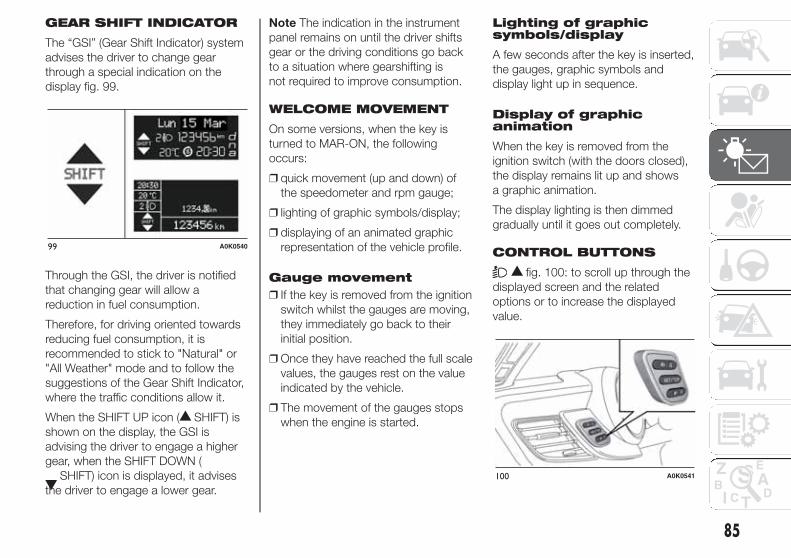
GEAR SHIFT INDICATOR
The “GSI” (Gear Shift Indicator) system
advises the driver to change gear
through a special indication on the
display fig. 99.
Through the GSI, the driver is notified
that changing gear will allow a
reduction in fuel consumption.
Therefore, for driving oriented towards
reducing fuel consumption, it is
recommended to stick to "Natural" or
"All Weather" mode and to follow the
suggestions of the Gear Shift Indicator,
where the traffic conditions allow it.
When the SHIFT UP icon ( SHIFT) is
shown on the display, the GSI is
advising the driver to engage a higher
gear, when the SHIFT DOWN (
SHIFT) icon is displayed, it advises
the driver to engage a lower gear.
Note The indication in the instrument
panel remains on until the driver shifts
gear or the driving conditions go back
to a situation where gearshifting is
not required to improve consumption.
WELCOME MOVEMENT
On some versions, when the key is
turned to MAR-ON, the following
occurs:
❒ quick movement (up and down) of
the speedometer and rpm gauge;
❒ lighting of graphic symbols/display;
❒ displaying of an animated graphic
representation of the vehicle profile.
Gauge movement
❒ If the key is removed from the ignition
switch whilst the gauges are moving,
they immediately go back to their
initial position.
❒ Once they have reached the full scale
values, the gauges rest on the value
indicated by the vehicle.
❒ The movement of the gauges stops
when the engine is started.
Lighting of graphicsymbols/display
A few seconds after the key is inserted,
the gauges, graphic symbols and
display light up in sequence.
Display of graphicanimation
When the key is removed from the
ignition switch (with the doors closed),
the display remains lit up and shows
a graphic animation.
The display lighting is then dimmed
gradually until it goes out completely.
CONTROL BUTTONS
fig. 100: to scroll up through the
displayed screen and the related
options or to increase the displayed
value.
99 A0K0540
100 A0K0541
85

SET/ : press briefly to access the
menu and/or go to next screen or
confirm the selection. Hold down to go
back to the standard screen.
: to scroll down through the
displayed menu and the related options
or to decrease the value displayed.
IMPORTANT The and
buttons activate different
functions according to the following
situations:
❒ within the menu, they allow you to
scroll up and down through the
options;
❒ during settings operations, they
increase or decrease values.
SETUP MENU
The menu comprises a series of
options which can be selected using
the and buttons to access
the different selection and setting
(Setup) operations indicated below.
Some options have a submenu. The
menu can be activated by briefly
pressing the SET/ button.
The menu comprises the following
options:
❒ MENU
❒ LIGHTING
❒ SPEED BEEP
❒ LIGHT SENSOR (for versions/
markets where provided)
❒ RAIN SENSOR (for versions/markets,
where provided)
❒ TRIP B ACTIVATION/DATA
❒ SET TIME
❒ SET DATE
❒ FIRST PAGE (for versions/markets
where provided)
❒ AUTOCLOSE
❒ MEASUREMENT UNIT
❒ LANGUAGE
❒ BUZZER VOLUME
❒ SEAT BELT BEEP/BUZZ
❒ SERVICE
❒ AIRBAG/PASSENGER BAG
❒ DAYTIME RUNNING LIGHTS
❒ ADAPTIVE LIGHTS (for versions/
markets, where provided)
❒ COURTESY LIGHTS
❒ MENU EXIT
Note On cars equipped with radio
navigator systems (for versions/
markets, where provided), some menu
items are shown on the navigator
display.
Selecting an option fromthe main menu without asubmenu:
❒ press the SET/ button briefly to
select the main menu setting you
wish to change;
❒ press buttons or (with
single presses) to select the new
setting;
❒ press the SET/ button briefly to
save the new setting and go back to
the previous main menu option.
Selecting an option fromthe main menu with asubmenu:
❒ briefly press the SET/ button to
display the first submenu option;
❒ press buttons or (with
single presses) to scroll through all
the submenu options;
❒ briefly press the SET/ button to
select the displayed submenu option
and to open the relevant settings
menu;
❒ press buttons or (with
single presses) to select the new
setting for this submenu option;
❒ press the SET/ button briefly to
save the new setting and go back to
the previous submenu option.
86
KN
OW
ING
TH
EIN
STR
UM
EN
TP
AN
EL

MENU ITEMS
IMPORTANT With Uconnect™ 5"
radio system (for versions/markets
where provided), or Uconnect™ 6.5"
Radio Nav system (for versions/
markets, where provided), some Menu
items are displayed and managed
through the system and not through the
instrument panel (refer to the dedicated
supplements).
Menu
This item allows you to access the
Setup Menu.
Press the or button to
select the various Menu options. Hold
down the SET/ button to return
to the standard screen.
Lighting (Car interiorlighting adjustment)(only with side lights on)
This function is used to set the
brightness of the instrument panel,
Uconnect™ system controls (for
versions/markets where provided) and
automatic climate control system
controls (for versions/markets where
provided) to 8 levels.
Proceed as follows to adjust the light
intensity:
❒ press button SET/ briefly. The
level set previously flashes on the
display;
❒ press button or to set
the required brightness level;
❒ briefly press the SET/ button to
go back to the menu screen or hold
the button down to go back to the
standard screen without saving.
Note On versions with reconfigurable
multifunction display, adjustment can
be made both with lights off ("Daytime"
mode brightness level) and with lights
on ("Nighttime" mode brightness level).
Speed Beep (Speedlimit)
With this function it is possible to set
the car speed limit (km/h or mph); when
this limit is exceeded the driver is
alerted.
To set the desired speed limit, proceed
as follows:
❒ briefly press the SET/ button: the
display will show the wording "Speed
Beep";
❒ press button or to select
speed limit activation ("On") or
deactivation ("Off");
❒ if the function is on, press or
to select the desired speed
limit and then press SET/ to
confirm.
IMPORTANT Setting is possible
between 30 and 200 km/h, or 20 and
125 mph, according to the previously
set unit. See the "Unit of Measurement"
paragraph described below. The
setting will increase/decrease by five
units each time button / is
pressed. Hold down the /
button to automatically
increase/decrease the setting rapidly.
Complete the adjustment with single
presses of the button when you
approach the desired value.
Briefly press the SET/ button to go
back to the menu screen or hold the
button down to go back to the
standard screen without saving.
To cancel the setting, proceed as
follows:
❒ briefly press the SET/ button,
"On" will flash in the display;
❒ press button , "Off" will flash on
the display;
❒ briefly press the SET/ button to
go back to the menu screen or hold
the button down to go back to the
standard screen without saving.
87

Headlight sensor(Automaticheadlight/dusk sensorsensitivity adjustment)(for versions/markets, where provided)
This function enables the headlights
to come on or go off depending on
external lighting conditions.
The dusk sensor sensitivity can be
adjusted according to 3 levels (level
1=minimum sensitivity, level 2=average
sensitivity, level 3=maximum sensitivity).
The higher the sensitivity set, the
lesser is the external light variation
needed to switch the lights on (e.g. with
a setting on level 3 at sunset the
headlights come on in advance in
relation to levels 1 and 2).
Proceed as follows to set the desired
adjustment:
❒ press the SET/ button briefly to
make the display flash the previously
set level;
❒ press or to make your
choice;
❒ briefly press the SET/ button to
go back to the menu screen or hold
the button down to go back to the
standard screen without saving.
Rain sensor (Rainsensor sensitivityadjustment)(for versions/markets, where provided)
This function allows you to adjust the
rain sensor sensitivity to 4 levels.
To set the required sensitivity level
proceed as follows:
❒ briefly press the SET/ button, the
previously set sensitivity level will
flash on the display;
❒ press the or button to
make the adjustment;
❒ briefly press the SET/ button to
go back to the menu screen or hold
the button down to go back to the
standard screen without saving.
Activation/Trip B data(Trip B enablement)
This function may be used to activate
(On) or deactivate (Off) the Trip B (partial
trip). For further information see “Trip
computer”.
Proceed as follows to switch the
function on and off:
❒ press the SET/ button briefly to
make the display flash "On" or "Off"
according to what was previously set;
❒ press or to make your
choice;
❒ briefly press the SET/ button to
go back to the menu screen or hold
the button down to go back to the
standard screen without saving.
Time adjustment (Clockadjustment)
This function enables to set the clock
through two submenus: "Time" and
"Format".
To carry out the adjustment, proceed as
follows:
❒ briefly press the SET/ button and
two submenus ("Time" and "Format")
will be displayed;
❒ press the or button to
switch between the two submenus;
❒ once you have selected a sub-menu
to be modified, press SET/
briefly;
❒ when the “Time” submenu is entered,
by briefly pressing SET/ the
hours flash on the display;
❒ press the or button to
make the adjustment;
❒ briefly press the SET/ button,
which makes the display flash the
"minutes";
❒ press the button or to
make the adjustment.
88
KN
OW
ING
TH
EIN
STR
UM
EN
TP
AN
EL

IMPORTANT The setting will increase or
decrease by one unit each time the
button or is pressed. Hold
down the button to increase/decrease
the setting rapidly and automatically.
Complete the adjustment with single
presses of the button when you
approach the desired value.
❒ When you select "Format": briefly
pressing the SET/ button makes
the display mode flash on the display;
❒ press button or to select
“24h” or “12h”.
When you have made the required
settings, briefly press the SET/
button to go back to the submenu
screen or hold the button down to go
back to the main menu screen without
saving the new settings.
Hold the SET/ button down again
to return to the standard screen or
to the main menu according to where
you are in the menu.
Set date (Setting thedate)
Using this function it is possible to
change the date (day – month – year).
Proceed as follows to start the update:
❒ briefly press the SET/ button:
the "year" starts flashing on the
display;
❒ press the or button to
make the adjustment;
❒ briefly press the SET/ button: the
"month" will flash on the display;
❒ press the or button to
make the adjustment;
❒ briefly press the SET/ button: the
“day” will flash on the display;
❒ press the button or to
make the adjustment.
IMPORTANT The setting will increase or
decrease by one unit each time the
button or is pressed. Hold
the button down to increase/decrease
the setting rapidly and automatically.
Complete the adjustment with single
presses of the button when you
approach the desired value.
Briefly press the SET/ button to go
back to the menu screen or hold the
button down to go back to the
standard screen without saving.
First page (Display ofinformation on the mainscreen)(for versions/markets, where provided)
This function allows you to choose
the information you would like to see on
the main screen. You can view the
date or the trip distance.
To make your choice, proceed as
follows:
❒ briefly press the SET/ button:
"Initial page" will be displayed;
❒ press the SET/ button again
briefly to display the "date" and
"engine info" options;
❒ press or to select the
information you wish to see on the
main page of the display;
❒ briefly press the SET/ button to
go back to the menu screen or hold
the button down to go back to the
standard screen without saving.
When the key is turned to MAR-ON
and the initial check stage is over, the
display will show the information
selected via the "First page" menu
function.
Autoclose (Automaticdoor lock operation withcar running)
When activated (On), this function locks
the doors automatically when the
vehicle speed exceeds 20 km/h.
Proceed as follows to activate or
deactivate this function:
❒ press the SET/ button briefly to
display a submenu;
89

❒ press the SET/ button briefly to
make the display flash "On" or "Off"
according to what was previously set;
❒ press or to make your
choice;
❒ press the SET/ button briefly to
return to the submenu screen or
hold the button down to return to the
main menu screen without saving;
❒ hold the SET/ button down
again to return to the standard
screen or to the main menu
according to where you are in the
menu.
Unit of measurement(Setting the unit ofmeasurement)
With this function it is possible to set
the measurement units through three
sub-menus: “Distance”, “Consumption”
and “Temperature”.
To set the desired measurement unit,
proceed as follows:
❒ briefly press the SET/ button to
display the three sub-menus;
❒ press button or to
navigate through the three
submenus;
❒ once the submenu to be modified
has been selected, briefly press
the SET/ button;
❒ when the “Distance” submenu is
entered: briefly pressing SET/
displays "km" or "mi" depending
on the previous setting;
❒ press or to make your
choice;
❒ when the “Consumption” submenu is
entered, pressing SET/ displays
km/l, l/100 km or mpg depending
on the previous setting;
If the set distance unit is "km", the fuel
consumption unit will be displayed in
km/l or l/100 km.
If the distance unit set is “mi” the fuel
consumption unit will be displayed
in “mpg”.
❒ press or to make your
choice;
❒ when the “Temperature” submenu is
entered, pressing SET/ displays
“°C” or “°F” depending on the
previous setting;
❒ press or to make your
choice;
When you have made the required
settings, briefly press the SET/
button to go back to the submenu
screen or hold the button down to go
back to the main menu screen without
saving the new settings.
Hold the SET/ button down again
to return to the standard screen or
to the main menu according to where
you are in the menu.
Language (Languageselection)
Display messages can be shown in
different languages: Italian, English,
German, Portuguese, Spanish, French,
Dutch, Turkish and Brazilian.
To set the desired language proceed as
follows:
❒ briefly press the SET/ button: the
previously set "language" starts
flashing on the display;
❒ press or to make your
choice;
❒ briefly press the SET/ button to
go back to the menu screen or hold
the button down to go back to the
standard screen without saving.
90
KN
OW
ING
TH
EIN
STR
UM
EN
TP
AN
EL

Warnings volume(Adjusting thealert/warning acousticsignal volume)
With this function it is possible to adjust
(to eight levels) the volume of the
acoustic signal which sounds in the
event of alerts and warning.
To set the desired volume proceed as
follows:
❒ press the SET/ button briefly,
making the display flash the
previously set volume "level";
❒ press the or button to
make the adjustment;
❒ briefly press the SET/ button to
go back to the menu screen or hold
the button down to go back to the
standard screen without saving.
Belt reminder(Reactivation of SBRbuzzer)(for versions/markets, where provided)
This function can be displayed only
after an Alfa Romeo Dealership has
deactivated the SBR system (see
paragraph “SBR system” in the “Safety”
chapter).
To reactivate this function, proceed as
follows:
❒ press the SET/ button briefly, the
display shows "OFF" flashing. Press
the or button and "On"
will appear;
❒ briefly press the SET/ button to
go back to the previous screen or
hold the button down to go back to
the standard screen without saving.
Service (Scheduledservicing)
This function allows you to display the
information about km/mileage intervals
or, for versions/markets, where
provided, time intervals for car
servicing.
To consult this information, proceed as
follows:
❒ briefly press the SET/ button: the
display shows when servicing is due
in km/mi or days (where provided)
or mi or days (where provided)
according to the previous setting (see
paragraph "Units of measurement");
❒ briefly press the SET/ button to
go back to the menu screen or hold
the button down to go back to the
standard screen.
IMPORTANT The “Scheduled Servicing
Plan” includes car maintenance at
fixed intervals (refer to the "Maintenance
and care" chapter). This is displayed
automatically, with ignition key at
MAR-ON, 2000 km (or equivalent value
in miles) before servicing or, where
provided, 30 days before servicing. It is
also displayed each time the key is
turned to MAR-ON or, for
versions/markets, where provided,
every 200 km (or equivalent value in
miles). Below this threshold servicing
indications are more frequent. The
display will be in km or miles according
to the unit of measurement set. When
the next scheduled service is
approaching, the word “Service” will
appear on the display, followed by the
number of kilometres/miles or days
(where provided) left, when the key is
turned to MAR-ON. Go to an Alfa
Romeo Dealership, where the
“Scheduled Servicing Plan” operations
will be performed and the message
will be reset.
When the service interval is reached
and for about 1000 km/600 mi or
30 days, a service due message is
displayed.
91

Passenger airbag/sidebag (front passengerside airbag and sidebag for pelvis, chestand shoulder protection- Side bag -activation/deactivation)
This function is used to activate/
deactivate the passenger side air bag.
Proceed as follows:
❒ press the SET/ button and, after
the message (Bag pass: Off) (to
deactivate) or (Bag pass: On) (to
activate) is displayed by pressing
buttons " " or " ", press
the SET/ button again;
❒ a confirmation request message will
appear on the display;
❒ by pressing the or
buttons select "Yes" (to confirm
activation/deactivation) or "No" (to
cancel);
❒ press the SET/ button briefly, a
message confirming the selection
will be displayed and you will return
to the menu screen or, pressing
the button for longer, you will return
to the standard screen without
memorising.
Daytime running lights(DRL)
With this function is possible to turn the
daytime running lights on and off.
Proceed as follows to activate or
deactivate this function:
❒ press the SET/ button briefly to
display a submenu;
❒ press the SET/ button briefly to
make the display flash "On" or "Off"
according to what was previously set;
❒ press or to make your
choice;
❒ press the SET/ button briefly to
return to the submenu screen or
hold the button down to return to the
main menu screen without saving;
❒ hold the SET/ button down
again to return to the standard
screen or to the main menu
according to where you are in the
menu.
AFS adaptive lights(Adaptive FrontlightSystem)(for versions/markets, where provided)
This function allows the AFS (Adaptive
Frontlight System) to be activated/
deactivated.
Proceed as follows to activate or
deactivate this function:
❒ press the SET/ button briefly to
display a submenu;
❒ press the SET/ button briefly to
make the display flash "On" or "Off"
according to what was previously set;
❒ press or to make your choice;
❒ press the SET/ button briefly
to return to the submenu screen
or hold the button down to return to
the main menu screen without
saving;
❒ hold the SET/ button down
again to return to the standard
screen or to the main menu
according to where you are in the
menu.
92
KN
OW
ING
TH
EIN
STR
UM
EN
TP
AN
EL

❒ interruption after locking using the
remote control
❒ interruption after a lock or other
action using the remote control
Proceed as follows to activate or
deactivate this function:
❒ press the SET/ button briefly to
make the display flash "On" or "Off"
according to what was previously set;
❒ press or to make your
choice;
❒ briefly press the SET/ button to
go back to the menu screen or hold
the button down to go back to the
standard screen without saving.
Menu exit
This is the last function that closes the
cycle of settings listed in the menu
screen.
Pressing the SET/ button briefly will
return the display to the standard
screen without saving.
Press the button to return to the
first menu option.
93
Courtesy lights(Activation/deactivationof “Greeting lights”)(for versions/markets, where provided)
With this function it is possible to turn
on the side lights, the number plate
lights and the ceiling lights for
approximately 25 seconds when the
doors or boot are opened using the
remote control, with the following
exceptions:
❒ interruption after 5 seconds from
when the door closes

CONTROL PANEL AND INSTRUMENTS.
VERSIONS WITH MULTIFUNCTION DISPLAY
A. Speedometer (speed indicator) – B. Multifunction display – C. Rev counter – D. Fuel level gauge with reserve warning light – E. Engine coolanttemperature indicator with overheating warning light
Warning lights supplied on diesel versions only. On diesel versions, the end of scale for the rev counter is 6000
rpm
IMPORTANT The illumination of the instrument panel graphics may vary according to version..
260
240
220
200180160
140
100
120
80
60
4020
0
1 2 0
0 Giri x 1000
2
1
3
4567
8
0
1
1/2
Benzina
50
130Acqua°C
90
Mon 15 Mar
101 A0K2300
94
KN
OW
ING
TH
EIN
STR
UM
EN
TP
AN
EL

VERSIONS WITH RECONFIGURABLE MULTIFUNCTION DISPLAY
A. Speedometer (speed indicator) – B. Reconfigurable multifunction display – C. Rev counter – D. Fuel level gauge with reserve warning light – E.Engine coolant temperature indicator with overheating warning light
Warning lights supplied on diesel versions only. On diesel versions, the end of scale for the rev counter is 6000
rpm
IMPORTANT The illumination of the instrument panel graphics may vary according to version.
260
240
220
200180160
140
100
120
80
60
4020
0
1 2 0
0 Giri x 1000
2
1
3
4567
8
0
1
1/2
Benzina
50
130Acqua°C
90
20:30
20 C°
2
Monday
15
March
123456 km
102 A0K2301
95

SPEEDOMETER (SPEEDINDICATOR)
This shows the speed of the car.
REV COUNTER
This indicates the engine rpm.
FUEL LEVEL GAUGE
This shows the amount of fuel left in the
fuel tank.
The warning light in the gauge lights up
when there are only 8 to 10 litres of
fuel remaining in the tank; if this
happens, refuel as soon as possible.
Do not travel with the fuel tank almost
empty: any gaps in fuel delivery could
damage the catalytic converter.
ENGINE COOLANTTEMPERATUREINDICATOR
The needle shows the temperature of
the engine coolant and starts supplying
indications when the fluid temperature
exceeds approx. 50°C.
Under normal conditions, the needle
assumes different positions within
the scale depending on the usage
conditions.
The warning light turns on to indicate
an overheating of the engine coolant. In
this case, stop the engine and contact
an Alfa Romeo Dealership.
TRIP COMPUTER
IN BRIEF
The Trip computer is used to display
information on car operation when
the key is turned to MAR.
This function is characterised by two
separate memories, called "Trip A"
and "Trip B", where the car's
"complete missions" (journeys) are
recorded in a reciprocally
independent manner.
Both memories can be reset: i.e. start
of a new journey.
“Trip A” is used to display the figures
relating to:
❒ Range
❒ Distance travelled
❒ Average fuel consumption
❒ Instant fuel consumption
❒ Average speed
❒ Trip time (driving time).
“Trip B” may be used to display the
figures relating to:
❒ Distance travelled B
❒ Average consumption B
96
KN
OW
ING
TH
EIN
STR
UM
EN
TP
AN
EL

❒ Average speed B
❒ Trip time B (driving time).
The “Trip B” function may be disabled
(see “Activating Trip B”). “Range” and
“Instant consumption" parameters
cannot be reset.
VALUES DISPLAYED
Range
This indicates the indicative distance
that may be travelled with the fuel in the
tank, assuming that driving conditions
do not change.
The display will show the reading '-----'
when the following events take place:
❒ range value lower than 50 km (or
30 mi)
❒ car parked with engine running for a
long period.
IMPORTANT The range can be affected
by several factors: driving style (see
“Driving style” paragraph in the
“Starting and driving” chapter), type of
route (motorway, towns and cities,
mountain roads, etc.), conditions of use
(load, tyre pressures, etc.). Trip
planning must therefore take the above
into account.
Distance covered
Shows the distance covered since the
start of the new journey.
Average consumption
Shows the approximate average fuel
consumption since the start of the new
journey.
Instantaneous consumption
This indicates the fuel consumption.
The value is constantly updated. The
display will show “- - - -” if the car
is parked with the engine running.
Average speed
This shows the average car speed as a
function of the overall time elapsed
since the start of the new journey.
Trip time
The time elapsed since the start of a
new journey.
INDICATIONS ON THEDISPLAY
Each time a value is displayed, the
following information is shown:
❒ animated icon in the upper part fig.
103;
❒ the word “Trip” (or “Trip A” or “Trip B”)
(B);
❒ the name, value and unit of
measurement of the selected
parameter (e.g. “Range 1500 km”)
(C).
After a few seconds the name and
value of the selected parameter are
replaced by an icon fig. 104.
103 A0K2011
104 A0K0007
97

The icons relating to the various
parameters are the following:
❒ "Range";
❒ "Average consumption A” (if
Trip A is active, or “B” if Trip B is
active);
❒ "Distance" (if Trip A is
active, or “B” if Trip B is active);
❒ "Instantaneous consumption";
❒ "Average speed A” (if Trip A
is active, or “B” if Trip B is active);
❒ "Trip time" (if Trip A is active, or
“B” if Trip B is active);
TRIP BUTTON 0.00
The TRIP 0.00 button is located on the
right hand stalkfig. 105. With the
ignition key turned to MAR-ON, this
button allows you to view the previously
described values and also set them to
zero to begin a new mission:
❒ short press: display various values;
❒ long press: values reset and start of a
new mission.
New mission
This begins after a reset:
❒ “manual” resetting by the user, by
pressing the relevant button;
❒ “automatic” resetting, when the “trip
distance” reaches 99999.9 km or
when the “Travel time” reaches
999:59 (999 hours and 59 minutes);
❒ after disconnection/reconnection of
the battery.
IMPORTANT The reset operation when
“Trip A” details are being displayed
only resets the information associated
with this function.
IMPORTANT The reset operation when
“Trip B” details are being displayed
resets only the information associated
with this function.
Start of journeyprocedure
With the ignition key at MAR-ON, reset
by pressing the TRIP 0.00 button and
holding it down for more than 2
seconds.
Trip Exit
You can automatically exit the Trip
function once all the values have been
displayed or by holding the SET/
button down for more than 1 second.
105 A0K0096
98
KN
OW
ING
TH
EIN
STR
UM
EN
TP
AN
EL

WARNING LIGHTS AND MESSAGES
IMPORTANT The warning light switches on together with a dedicated message and/or acoustic signal when applicable. These
indications are indicative and precautionary and as such must not be considered as exhaustive and/or alternative to the
information contained in the Owner Handbook, which you are advised to read carefully in all cases. Always refer to the
information in this section in the event of a failure indication.
IMPORTANT Failure indications displayed are divided into two categories: very serious and less serious failures. Serious faults
are indicated by a repeated and prolonged warning "cycle". Less serious faults are indicated by a warning "cycle" with a shorter
duration. The display cycle of both categories can be interrupted. The instrument panel warning light will stay on until the
cause of the malfunction is eliminated.
WARNING LIGHTS IN INSTRUMENT PANEL
Warning lights onpanel What it means What to do
red
LOW BRAKE FLUID/HANDBRAKE ENGAGED
The warning light switches on when the key is
turned to MAR-ON, but it should switch off after a
few seconds.
Low brake fluid level
The warning light (or symbol on the display)
switches on when the level of the brake fluid in
the reservoir falls below the minimum level,
possibly due to leaks in the circuit.
The display shows the dedicated message.
Restore the brake fluid level, then check that the
warning light has switched off.
If the warning light stays on, contact an Alfa
Romeo Dealership.
Handbrake applied
The warning light (or symbol on the display)
switches on when the handbrake is engaged. If
the car is moving an acoustic signal is also
emitted.
Release the handbrake, then check that the
warning light has switched off.
If the warning light (or symbol on the display)
stays on, contact an Alfa Romeo Dealership.
99

Warning lights onpanel What it means What to do
red
amber
EBD FAILURE
The simultaneous switching on of the (red)
and (amber) warning lights with the engine
on, indicates either a fault of the EBD system or
that the system is not available. In this case, the
rear wheels may suddenly lock and the vehicle
may swerve when braking sharply.
The display shows the dedicated message.
Drive very carefully to the nearest Alfa Romeo
Dealership to have the system inspected
immediately.
red
AIRBAG FAILURE
When the key is turned to MAR-ON, the warning
light switches on but should switch off after a few
seconds.
If the warning light switches on constantly, this
indicates a fault in the airbag system.
The display shows the dedicated message.
63) 64)
red
SEAT BELTS NOT FASTENED
(for versions/markets, where provided)
The warning light switches on constantly with the
car stationary and the driver’s seat belt not
fastened.
The warning light flashes and a buzzer sounds if
the car is in motion and the front seat belts are
not correctly fastened.
For permanent deactivation of the SBR (Seat Belt
Reminder) system buzzer, contact an Alfa Romeo
Dealership. The system can be reactivated using
the Setup Menu.
100
KN
OW
ING
TH
EIN
STR
UM
EN
TP
AN
EL

Warning lights onpanel What it means What to do
red
ALTERNATOR FAILURE
The warning light switches on when the ignition
key is turned to MAR-ON, but it should switch off
as soon as the engine has started (with the
engine idling a brief delay before switching off is
acceptable).
If the warning light (or symbol on the display)
stays on constantly or flashing, contact an Alfa
Romeo Dealership as soon as possible.
WARNING
63) If the warning light does not switch on when the key is turned to MAR-ON or if it stays on when driving (together
with the message on the display), there may be a fault in the restraint systems; in this case, the airbags or
pretensioners may not deploy in the event of an accident or, in a lower number of cases, they could deploy
erroneously. Before proceeding, contact an Alfa Romeo Dealership to have the system checked immediately.
64) Failure of the warning light is signalled by the flashing for longer than the usual 4 seconds of the warning light
(located in the trim above the internal rear view mirror). In addition, the airbag system automatically disables the
passenger side airbag. In this case, the warning light may not indicate a fault in the restraint systems. Before
proceeding, contact an Alfa Romeo Dealership to have the system checked immediately.
101

Warning lights onpanel What it means What to do
red
LOW ENGINE OIL PRESSURE
When the key is turned to MAR-ON the warning light comes on, but
should go out as soon as the engine is started.
The warning light switches on constantly together with a message on the
display (for versions/markets, where provided) when the system detects
that engine oil pressure is low.
12)
IMPORTANT
12) If the warning light switches on when driving, stop the engine immediately and contact an Alfa Romeo
Dealership.
102
KN
OW
ING
TH
EIN
STR
UM
EN
TP
AN
EL

Warning lights onpanel What it means What to do
red
DEGRADED ENGINE OIL (for versions/markets, where provided)
The warning light will turn on flashing together with a dedicated message
on the display (for versions/markets where provided).
Depending on the versions, the warning light flashing modes are as
follows:
- for 1 minute every two hours;
- for 3 minute cycles with the warning light off for intervals of 5 seconds
until oil is changed.
After the initial warning, each time the engine is started up, the warning
light will continue to flash in the same mode, until the oil is changed. A
specific message will appear on the display (for versions/markets, where
provided) in addition to the warning light. If the warning light flashes, this
does not mean that there is a fault, but simply informs that it is now
necessary to change the oil as a result of regular use of the car. Engine oil
deterioration is accelerated by:
- mainly town use of the car which makes the DPF regeneration process
more frequent;
- use of the vehicle for short drives, in which the engine does not have
time to reach its regular operating temperature;
- repeated interruptions of the regeneration process, signalled by the DPF
warning light switching on.
Contact an Alfa Romeo
Dealership as soon as
possible.
65) 66)
103

WARNING
65) Deteriorated engine oil should be replaced as soon as possible after the warning light comes on, and never more
than 500 km after it first switches on. Failure to observe the above indications may result in severe damage to the
engine and invalidate the warranty. Remember that when this warning light comes on, it does not mean that the level
of engine oil is low, so if it flashes you must not top up the engine oil.
66) If the warning light flashes with the car in motion, contact an Alfa Romeo Dealership.
104
KN
OW
ING
TH
EIN
STR
UM
EN
TP
AN
EL

Warning lights onpanel What it means What to do
red
ENGINE COOLANT TEMPERATURE TOO
HIGH
When the key is turned to MAR-ON, the warning
light switches on but should switch off after a few
seconds. The warning light turns on when the
engine is overheated.
The display shows the dedicated message.
When driving normally: stop the car, switch off the
engine and check that the water level in the
reservoir is not below the MIN mark. If it is, wait
for the engine to cool down, then slowly and
carefully open the cap, top up with coolant and
check that the level is between the MIN and MAX
marks on the reservoir. Also check visually for any
fluid leaks. Should the warning light turn on again
at the next start-up, contact an Alfa Romeo
Dealership.
If the car is used under demanding conditions
(e.g. in high-performance driving): slow down
and, if the warning light stays on, stop the car.
Wait for 2 or 3 minutes with the engine running
and slightly accelerated to further favour the
coolant circulation. Then stop the engine. Check
the correct coolant level as described above.
IMPORTANT Over demanding routes, it is
advisable to keep the engine on and slightly
accelerated for a few minutes before switching it
off.
105

Warning lights onpanel What it means What to do
red
ALFA TCT FAILURE
(for versions/markets, where provided)
When the key is turned to MAR-ON, the warning
light switches on but should switch off after a few
seconds.
The warning light flashes (together with a
message in the display and an acoustic signal) to
indicate that the transmission is faulty.
The warning light can switch on even in case of
transmission overheating, after a particularly
demanding use. In this case an engine
performance limitation is carried out.
Contact an Alfa Romeo Dealership as soon as
possible.
If it is necessary to start the engine with a
transmission failure, follow the procedure
described in the "Alfa TCT" paragraph, in chapter
"Starting and driving".
red
INCOMPLETE DOOR LOCKING
(for versions/markets, where provided)
The warning light (or symbol on the display) lights
up when one or more doors or the tailgate are not
closed correctly. An acoustic signal is activated
with the doors open and the car moving.
On some versions the warning light (or symbol on
the display) also lights up when the bonnet is not
closed correctly.
red
SPEED LIMIT EXCEEDED
(for versions/markets, where provided)
The warning light switches on when the car
exceeds the speed limit value set in the Setup
Menu (e.g. 120 km/h).
On some versions a message is shown along
with a symbol on the display, and an acoustic
signal is emitted.
106
KN
OW
ING
TH
EIN
STR
UM
EN
TP
AN
EL

Warning lights onpanel What it means What to do
red
DUAL PINION ACTIVE STEERING FAILURE
(for versions/markets, where provided)
When the key is turned to MAR-ON, the warning
light switches on but should switch off after a few
seconds.
If the warning light (or symbol on the display)
remains on, you may not have steering assistance
and the effort required to operate the steering
wheel could be notably increased; steering is,
however, possible.
The display shows the dedicated message.
Contact an Alfa Romeo Dealership as soon as
possible.
IMPORTANT After the battery is disconnected,
the steering must be initialised. The warning light
switches on to indicate this. To carry out this
procedure, simply turn the steering wheel all the
way from one end to the other or drive in a
straight line for about 100 metres.
Warning lights onpanel What it means What to do
amber
ALFA ROMEO CODE SYSTEM FAILURE/
ALARM FAILURE
(for versions/markets, where provided)
The warning light (or symbol on the display) will
come on (on some versions, with a message on
the display) to indicate an Alfa Romeo CODE
system or alarm failure (for versions/markets,
where provided).
Contact an Alfa Romeo Dealership as soon as
possible.
Break-in attempt
If this warning light flashes or, on some versions, if
the symbol appears in the display (together with a
message) this indicates a break-in attempt.
Contact an Alfa Romeo Dealership as soon as
possible.
107

Warning lights onpanel What it means What to do
amber
FUEL RESERVE/LIMITED RANGE
The warning light turns on when about 8 - 10
litres of fuel are left in the tank.
When the remaining range is lower than approx.
50 km (or equivalent value in miles), on some
versions the display will show a warning
message.
67)
108
KN
OW
ING
TH
EIN
STR
UM
EN
TP
AN
EL
WARNING
67) If the warning light flashes with the car in motion, contact an Alfa Romeo Dealership.

Warning lights onpanel What it means What to do
amber
GENERAL FAILURE
(for versions/markets, where provided)
The warning light switches on in the
circumstances indicated below.
In these cases contact an Alfa Romeo Dealership
to have the fault fixed as soon as possible.
Fuel cut-off
The warning light switches on when the fuel
cut-off system intervenes. The display shows the
dedicated message.
Start&Stop system failure
(for versions/markets, where provided)
The warning light comes on when a fault is
detected in the Start&Stop system.
Rain sensor failure
(for versions/markets, where provided)
The warning light switches on when a rain sensor
fault is detected.
Parking sensor failure
(for versions/markets, where provided)
See the following description for “Parking sensor
failure”.
109

Warning lights onpanel What it means What to do
amber
GENERAL FAILURE
(for versions/markets, where provided)
The warning light switches on in the
circumstances indicated below.
In these cases contact an Alfa Romeo Dealership
to have the fault fixed as soon as possible.
Dusk sensor failure
(for versions/markets, where provided)
This warning light comes on when a dusk sensor
fault is detected.
Engine oil pressure sensor failure
The warning light comes on when the engine oil
pressure sensor is faulty. The display shows the
dedicated message.
AFS adaptive lights failure
(for versions/markets, where provided)
The warning light switches on when a fault is
detected with the AFS adaptive lights (see the
“AFS adaptive lights” paragraph in the "Knowing
your vehicle" section). The display shows the
dedicated message.
Anti-pinch system failure
The warning light comes on when a fault is
detected in the electric window anti-pinch
system. The display shows the dedicated
message.
110
KN
OW
ING
TH
EIN
STR
UM
EN
TP
AN
EL

Warning lights onpanel What it means What to do
amber
Exterior lights failure
The warning light switches on when a fault is
detected on one of the following lights:
❒ daytime running lights (DRL)
❒ side lights
❒ direction indicators
❒ rear fog lights
❒ number plate lights
The fault relating to these lights may be caused
by: one or more blown fuses, one or more blown
bulbs or a broken electrical connection.
Check, and if necessary replace the fuses
involved, in accordance with the "Fuse
replacement" paragraph, in chapter "In an
emergency". If this does not resolve the fault,
check, and if necessary replace, the bulbs
involved, in accordance with the "External bulb
replacement" paragraph, in chapter "In an
emergency".
Should this operation also fail to resolve the fault,
contact an Alfa Romeo Dealership, for a
comprehensive check of the electrical system.
amber
REAR FOG LIGHTS
This warning light comes on when the rear fog
lights are switched on.
111

Warning lights onpanel What it means What to do
amber
ABS FAILURE
When the key is turned to MAR-ON, the warning
light switches on but should switch off after a few
seconds.
The warning light (or symbol on the display)
switches on when the system is inefficient. In this
case the braking system will work as normal, but
without the extra performance offered by the
ABS.
The display shows the dedicated message.
Drive carefully and contact an Alfa Romeo
Dealership as soon as possible.
amber
BRAKE PAD WEAR
(for versions/markets, where provided)
The warning light (or symbol on the display)
switches on when the front and rear brake pads
are worn.
The display shows the dedicated message.
Have them replaced as soon as possible.
amber
PASSENGER SIDE AIRBAG DEACTIVATED
The warning light (located in the trim above the
internal rear view mirror) switches on deactivating
the front passenger side airbag.
With front passenger airbag on, when the ignition
key is turned to MAR-ON, the warning light
switches on constantly for several seconds and
then it should switch off.
If the warning light flashes, this indicates a fault
in the warning light.
68)
112
KN
OW
ING
TH
EIN
STR
UM
EN
TP
AN
EL

Warning lights onpanel What it means What to do
amber
INJECTION/EOBD SYSTEM FAILURE
In normal conditions, when the ignition key is turned to
MAR-ON the warning light switches on, but it should
switch off as soon as the engine is started. The operation
of warning light may be checked by the traffic police
using specific devices. Comply with the laws and
regulations of the country where you are driving.
13)
If the warning light remains on or switches on whilst
driving, it means that the injection system is not working
properly. The warning light on constantly signals a
malfunction in the supply/ignition system which could
cause high exhaust emissions, a possible loss of
performance, poor driveability and high consumption.
On some versions, the display shows the dedicated
message. The warning light goes out after the fault
disappears: the indication is stored in the system.
Under these conditions, you may continue
travelling at a moderate speed without
demanding excessive effort from the
engine. Prolonged use of the car with the
warning light on constantly may cause
damage.
Contact an Alfa Romeo Dealership as
soon as possible.
Petrol engines only
If the warning light flashes, it means that the catalytic
converter may be damaged.
In this case, release the accelerator pedal
to lower the speed of the engine until the
warning light stops flashing. Continue the
journey at moderate speed, trying to avoid
driving conditions that may cause further
flashing and contact an Alfa Romeo
Dealership as soon as possible.
113

Warning lights onpanel What it means What to do
amber
GLOW PLUG HEATING/GLOW PLUG
HEATING FAILURE (diesel versions)
This warning light switches on when the key is
turned to MAR-ON. It will switch off as soon as
the heater plugs have reached a preset
temperature. The engine can be started as soon
as the warning light switches off.
IMPORTANT In mild or high temperature
conditions, the warning light comes on for a very
short time only.
Glow plug preheating failure
The warning light will flash (a message will appear
on the display, on some versions) to indicate a
fault in the glow plugs preheating system.
Contact an Alfa Romeo Dealership as soon as
possible.
amber
WATER IN DIESEL FILTER (diesel versions)
The warning light remains on constantly when
driving (together with a message in the display),
to indicate the presence of water in the diesel
filter.
14)
WARNING
68) Failure of the warning light is indicated by the warning light switching on. In addition, the airbag system
automatically disables the passenger side airbag. Before proceeding, contact an Alfa Romeo Dealership to have the
system checked immediately.
114
KN
OW
ING
TH
EIN
STR
UM
EN
TP
AN
EL

IMPORTANT
13) If, turning the ignition key to MAR-ON, the warning light does not turn on or if it turns on steadily or flashing
when travelling (on certain versions together with the message on the display), contact an Alfa Romeo Dealership
as soon as possible.
IMPORTANT
14) The presence of water in the fuel supply system circuit may cause severe damage to the injection system and
irregular engine operation. If the warning light comes on in the instrument panel (together with a message in the
display) contact an Alfa Romeo Dealership as soon as possible to bleed the system. If the above indications come
on immediately after refuelling, water has probably been poured into the tank: turn the engine off immediately and
contact an Alfa Romeo Dealership.
115

Warning lights onpanel What it means What to do
amber
DPF CLEANING (particulate trap) in progress
(diesel versions with DPF only)
When the key is turned to MAR-ON, the warning
light switches on but it should switch off after a
few seconds. The warning light switches on
constantly to indicate that the DPF system needs
to eliminate the trapped pollutants (particulate)
through the regeneration process.
The warning light does not come on during every
DPF regeneration, but only when driving
conditions require that the driver is notified. To
turn off the warning light, keep the car in motion
until the regeneration process is over.
On average, the process lasts 15 minutes.
Optimal conditions for completing the process are
achieved by travelling at 60 km/h with engine
speed above 2000 rpm.
When this warning light switches on, it does not
indicate a car failure and thus it should not be
taken to a workshop. On some versions, together
with the warning light switching on, the display
shows a dedicated message.
69)
116
KN
OW
ING
TH
EIN
STR
UM
EN
TP
AN
EL
WARNING
69) Always drive at a speed appropriate to the traffic conditions, the weather and traffic regulations. The engine can be
stopped even if the DPF warning light is on: however, repeated interruptions of the regeneration process could cause
premature deterioration of the engine oil. For this reason, always wait until the warning light switches off before
stopping the engine as described above. It is not advisable to complete DPF regeneration with the car stationary.

Warning lights onpanel What it means What to do
amber
iTPMS SYSTEM
When the key is turned to MAR-ON, the warning
light switches on but should switch off after a few
seconds.
IMPORTANT Do not continue driving with one or
more flat tyres as handling may be
compromised. Stop the car, avoiding sharp
braking and steering. Repair immediately using
the dedicated kit (see the "Replacing a wheel"
paragraph in the "In an emergency" section) and
contact an Alfa Romeo Dealership as soon as
possible.
iTPMS failure/iTPMS temporarily deactivated
The warning light flashes for about 75 seconds and
then stays on constantly (together with a message
on the display) (see “Operating conditions”
paragraph) to indicate that the system is
temporarily deactivated or faulty.
The system goes back to normal operation when
the operating conditions allow it. If this is not the
case, carry out the Reset procedure after restoring
the normal operating conditions.
If the malfunction warning persists, contact an
Alfa Romeo Dealership as soon as possible.
117

Warning lights onpanel What it means What to do
amber
Low tyre pressure
The warning light switches on constantly to
indicate that the tyre pressure is lower than the
recommended value, in order to guarantee long
tyre life and low fuel consumption, or to indicate a
slow loss of pressure.
In this way the iTPMS warns the driver that one or
more tyres may be flat and liable to puncture. In
this case it is advisable to restore the correct
pressure value (see the "Wheels" paragraph in the
"Technical specifications" section).
Once the normal operating conditions of the car
are restored, carry out the Reset procedure.
In any situation in which the message on the
display is "See manual", it is ESSENTIAL to refer
to the contents of the "Wheels" paragraph in the
"Technical specifications" section, strictly
complying with the indications that you find
there.
IMPORTANT Do not continue driving with one or
more flat tyres as handling may be
compromised. Stop the car, avoiding sharp
braking and steering.
118
KN
OW
ING
TH
EIN
STR
UM
EN
TP
AN
EL

Warning lights onpanel What it means What to do
amber
ELECTRONIC STABILITY CONTROL (ESC)
SYSTEM
When the ignition key is turned to MAR-ON, the
warning light switches on, but should switch off
as soon as the engine is started.
Intervention by the system is indicated by the
flashing of the warning light: it indicates that the
car is in critical stability and grip conditions.
If the warning light (or symbol on the display)
does not switch off, or if it stays on with the
engine running, this means that an ESC system
fault is present.
On some versions, the display shows the
dedicated message.
Contact an Alfa Romeo Dealership as soon as
possible to have the problem diagnosed and
resolved.
119

Warning lights onpanel What it means What to do
amber
ELECTRONIC STABILITY CONTROL (ESC)
SYSTEM
ASR system failure
When the ignition key is turned to MAR-ON, the
warning light switches on, but should switch off
as soon as the engine is started.
The warning light will flash while driving to indicate
that the ASR system is intervening.
If the warning light (or symbol on the display)
does not switch off, or if it stays on with the
engine running, this means that an ASR system
malfunction has been detected.
On some versions, the display shows the
dedicated message.
In this case, contact an Alfa Romeo Dealership as
soon as possible.
Hill Holder system failure
The warning light switches on together with the
symbol and corresponding message on the
display to indicate Hill Holder system failure.
In this case, contact an Alfa Romeo Dealership as
soon as possible.
120
KN
OW
ING
TH
EIN
STR
UM
EN
TP
AN
EL

Warning lights onpanel What it means What to do
green
CRUISE CONTROL (for versions/markets,
where provided)
This warning light switches on when the ignition
key is turned to MAR-ON, but it should switch off
after a few seconds, if the Cruise Control is
deactivated. The warning light switches on when
the Cruise Control ring nut is turned to the ON
position (see the “Cruise Control” paragraph in
the "Knowing your vehicle" section).
The display shows the dedicated message.
green
SIDE LIGHTS
The warning light switches on when the side
lights are activated.
FOLLOW ME HOME
The warning light switches on (together with a
message shown on the display) when this device
is in use (see the "Exterior lights" paragraph in the
"Knowing your vehicle" section).
2
green
DIPPED BEAM HEADLIGHTS
The warning light switches on when the dipped
beam headlights are turned on.
green
FOG LIGHTS
The warning light comes on when the fog lights
are turned on.
121

Warning lights onpanel What it means What to do
green
LEFT-HAND DIRECTION INDICATOR
The warning light switches on when the direction
indicator control lever is moved downwards or,
together with the right direction indicator, when
the hazard warning light button is pressed.
green
RIGHT-HAND DIRECTION INDICATOR
The warning light turns on when the direction
indicator control lever is moved upwards or,
together with the left direction indicator, when the
hazard warning light button is pressed.
Warning lights onpanel What it means What to do
blue
MAIN BEAM HEADLIGHTS
The warning light switches on when the main
beam headlights are turned on.
122
KN
OW
ING
TH
EIN
STR
UM
EN
TP
AN
EL

SYMBOLS AND MESSAGES ON THE DISPLAY
Symbol on thedisplay What it means What to do
FUEL CUT-OFF SYSTEM
On some versions the display will show a
message + symbol if the fuel cut-off intervenes.
For the procedure to restore the fuel cut-off
system see the “Controls" paragraph in the
"Knowing your vehicle" section. If it is still not
possible to restore the fuel supply, contact an Alfa
Romeo Dealership.
POSSIBLE ICE ON ROAD
On versions equipped with reconfigurable
multifunction display, a message and a symbol
will appear on the display when the outside
temperature falls to or below 3°C.
On versions with “Multifunction display” only the
dedicated message is shown.
IMPORTANT In the event of outside temperature
sensor failure, the digits that indicate the value are
replaced by dashes.
BRAKE LIGHT FAILURE
On some versions the display will show a
message + symbol if there is a fault in the brake
lights.
The fault may be caused by a blown bulb, a
blown protection fuse or an interruption of the
electrical connection.
DUSK SENSOR FAILURE
(for versions/markets, where provided)
On some versions the display will show a
message + symbol if there is a fault in the dusk
sensor.
Go to an Alfa Romeo Dealership to have the fault
fixed as soon as possible.
123

Symbol on thedisplay What it means What to do
RAIN SENSOR FAILURE
(for versions/markets, where provided)
On some versions the display will show a
message + symbol if there is a fault in the rain
sensor.
Go to an Alfa Romeo Dealership to have the fault
fixed as soon as possible.
PARKING SENSOR FAILURE
(for versions/markets, where provided)
On some versions the display will show a
message + symbol if there is a fault in the parking
sensors.
Go to an Alfa Romeo Dealership to have the fault
fixed as soon as possible.
124
KN
OW
ING
TH
EIN
STR
UM
EN
TP
AN
EL

Symbol on thedisplay What it means What to do
START&STOP SYSTEM ACTIVATION/
DEACTIVATION (for versions/markets, where
provided)
Start&Stop system activation
A message will appear on the display when the
Start&Stop system is activated. In this case the
LED located on the button is off (see the
“Start&Stop” paragraph in this chapter).
Start&Stop system deactivation
Versions with multifunction display: a message is
displayed when the Start&Stop system is
deactivated.
Versions with reconfigurable multifunction display:
the symbol + message appear on the display
when the Start&Stop system is deactivated.
The LED on the button is on when the system
is deactivated.
START&STOP FAILURE
If the Start&Stop system is faulty the (versions
with multifunction display) or (versions with
reconfigurable multifunction display) symbol
flashes on the display.
For versions/markets, where provided, a warning
message is also displayed.
In these cases contact an Alfa Romeo Dealership
to have the fault fixed as soon as possible.
125

Symbol on thedisplay What it means What to do
DISPLAY OF SELECTED DRIVING MODE
(“Alfa DNA” system)
On versions equipped with a "Reconfigurable
multifunction display", a message and the symbol
associated with the selected driving mode
“DYNAMIC”, “NATURAL” or “ALL WEATHER” are
shown. A warning message is shown on the
display if one of these driving modes is not
available.
On versions equipped with "Multifunction
display", a letter ("d" or "a") associated with the
selected driving mode is shown together with a
dedicated message.
126
KN
OW
ING
TH
EIN
STR
UM
EN
TP
AN
EL

SAFETY
The chapter that you are about to readis very important: it describes thesafety systems with which the car isequipped and provides instructions onhow to use them correctly.
SEAT BELTS ..................................128
SBR SYSTEM (SEAT BELTREMINDER) ....................................129
PRETENSIONERS...........................131
CARRYING CHILDREN SAFELY......133
FITTING “UNIVERSAL” CHILDSEAT (WITH SEAT BELTS)...............134
PREPARATION FOR “ISOFIX”CHILD SEAT ...................................137
FRONT AIRBAGS............................140
SIDE AIRBAGS (SIDE BAGS -WINDOW BAGS).............................144
127

SEAT BELTS
USING THE SEAT BELTS
The belt should be worn keeping the
torso straight and rested against the
backrest.
To fasten the seat belts, hold the
tongue A fig. 106 and insert it into the
buckle B, until it clicks into place.
On removal of the belt, if it jams, let it
rewind for a short stretch, then pull
it out again without jerking.
To unfasten the seat belts, press button
C and guide the seat belt with your
hand while it is rewinding, to prevent it
from twisting. 70) 71) 72)
The retractor may lock when the car is
parked on a steep slope: this is
perfectly normal. Furthermore, the
retractor mechanism locks the belt if it
is pulled sharply or in the event of
sudden braking, collisions or
high-speed bends.
The rear seat is fitted with inertia seat
belts with three anchor points and a
retractor.
Wear the rear seat belts as illustrated in
fig. 107.
IMPORTANT The backrest is correctly
secured when the red band B fig.
108 on backrest folding handle A
disappears. This red band indicates
that the backrest is not secured.
IMPORTANT When putting the rear
seats back to their normal position,
make sure the seat belts are positioned
so they are ready to use.
WARNING
70) Never press button C fig. 106
while travelling.
71) Remember that, in the event of
an accident, the rear seat
passengers not wearing seat belts
are exposed to a very serious
risk and also represent a serious
danger for the front seat
occupants.
106 A0K0659
107 A0K0161
108 A0K0628
128
SA
FE
TY

72) Make sure that the backrest is
correctly secured on both sides
("red bands" B fig. 108 not visible)
to prevent it from moving forward
in the event of sharp braking,
causing injuries to occupants.
SBR SYSTEM (SeatBelt Reminder)
This system comprises an acoustic
warning which, in conjunction with the
warning lights flashing on the
instrument panel, advises the front seat
passengers if their seat belt has not
been fastened.
On some versions there is also a panel
(provided as an alternative to the
warning light on the instrument panel)
located above the interior rear view
mirror, which warns the front and back
seat passengers through acoustic
and visual signals if their seat belts have
not been fastened.
Contact an Alfa Romeo Dealership to
deactivate this acoustic warning
permanently.
The acoustic warning can be
reactivated at any time through the
Setup Menu (see "Menu options"
paragraph in the “Knowing the
instrument panel” chapter).
The warning lights may be red or green
and operate as follows:
❒ 1 = front left seat (driver status for
left-hand drive versions);
❒ 2 = rear left seat (passenger);
❒ 3 = rear centre seat (passenger);
❒ 4 = rear right seat (passenger);
❒ 5 = front right seat (passenger status
for left-hand drive versions).
109 A0K0075
129

Driver
If the driver is the only occupant and
their seat belt is not fastened, when 20
km/h is exceeded or when travelling
at a speed between 10 and 20 km/h for
longer than 5 seconds, an acoustic
signal cycle will be started for the front
seats (continuous acoustic signal for
6 seconds followed by a 90 second
beep). The warning light will flash.
The warning lights will stay on
constantly at the end of the cycle until
the engine is stopped. The acoustic
signal will be interrupted immediately
when the driver’s seat belt is fastened
and the warning light will turn green.
The reminder cycle (acoustic and visual)
will be repeated as described above
and the red warning light will flash if the
seat belt is unfastened again while
travelling.
Passenger
A similar situation applies to the front
passenger, with the difference that the
warning light turns green and the
indication is also interrupted when the
passenger leaves the car.
If both front seat belts are unfastened a
few seconds apart while the car is
travelling, the acoustic signal will refer
to the most recent event and the two
warning lights will proceed with the
visual indication independently.
REAR SEATS (warninglight no. 2, no. 3 and no.4)
For the rear seats, the reminder cycle is
only activated when any seat belt is
unfastened (flashing red).
In this condition, the warning light for
the seat belt which has been
unfastened will flash (red) for
approximately 30 seconds. An acoustic
signal is also emitted.
The visual indication (flashing red) will
start and stop independently for each
warning light if several seat belts are
unfastened. The warning light will
become green when the relevant seat
belt is fastened again.
The rear seat warning lights will switch
off, regardless of the state of the belt
(red or green) approximately 30
seconds after the last signal.
IMPORTANT
The warning lights are all off if all seat
belts (front and rear) are already
fastened when the ignition key is turned
to MAR.
All warning lights switch on when at
least one belt changes from fastened to
unfastened or vice versa.
130
SA
FE
TY FRONT SEATS (warning
light no. 1 = driver andno. 5 = passenger)

PRETENSIONERS
The car is equipped with front seat belt
pretensioners, which draw back the
seat belts by several centimetres in the
event of a violent frontal impact. This
guarantees the perfect adherence
of the seat belts to the occupants’
bodies before the restraining action
begins.
It is evident that the pretensioners have
been activated when the belt withdraws
towards the reel.
The car is also equipped with a second
pretensioner (in the kick plate area).
Its activation is signalled by the
shortening of the metal cable.
A slight discharge of smoke may be
produced during the activation of the
pretensioner. This is not harmful and
does not indicate the start of a fire.
IMPORTANT To obtain the highest
degree of protection from the action of
the pretensioner, wear the seat belt
tight to the chest and pelvis.
The pretensioner does not require any
maintenance or lubrication: any
changes to its original conditions will
invalidate its efficiency. If, due to
unusual natural events (floods, sea
storms, etc.), the device has been
affected by water and/or mud, contact
an Alfa Romeo Dealership to have it
replaced.
LOAD LIMITERS
To increase protection, the front seat
belt reels contain a load limiter which
controls the force acting on the chest
and shoulders during the belt
restraining action in the event of a
head-on collision.
73)
15)
GENERALINSTRUCTIONS FORUSING THE SEAT BELTS
Respect and ensure that all the other
occupants of the car respect the local
laws in force regarding the use of seat
belts. Always fasten the seat belts
before starting off.
74) 75) 76)
Seat belts must also be worn by
pregnant women: the risk of injury in
the event of an accident is reduced for
them and the unborn child if they are
wearing a seat belt.
Pregnant women must position the
lower part of the belt very low down so
that it passes over the pelvis and under
the abdomen fig. 110.
The belt must not be twisted. The
upper part must pass over the shoulder
and cross the chest diagonally. The
lower part must adhere to the pelvis fig.
111, not to the abdomen of the
occupant. Never use devices (clips,
clamps, etc.) to hold the seat belt away
from your body.
110 A0K0250
131

Each seat belt must be used by only
one person. Never travel with a child
sitting on a passenger’s lap and a single
belt to protect them both fig. 112. In
general, do not place any objects
between the person and belt.
SEAT BELTMAINTENANCE
❒ Always use the seat belt well
stretched and never twisted; make
sure that it is free to run without
obstructions;
❒ replace the belt after an accident of a
certain severity even if it does not
appear to be damaged. Always
replace the belt if the pretensioners
were deployed;
❒ hand wash the seat belts with water
and neutral soap, rinse and leave to
dry in the shade. Never use strong
detergents, bleach, paints or any
other substance which could
damage the belt fibres;
❒ prevent the retractors from getting
wet: their correct operation is only
guaranteed if water does not get
inside;
❒ replace the seat belt when there is
wear or cuts.
WARNING
73) The pretensioner may be used
only once. After its activation,
contact an Alfa Romeo Dealership
to have it replaced.
74) Removing or otherwise
tampering with pretensioner and
seat belt components is strictly
prohibited. Any operations on
these components must be
performed by qualified and
authorised technicians. Always
contact an Alfa Romeo
Dealership.
75) For maximum protection, keep
the backrest upright, lean back
into it and make sure the seat belt
fits closely across your chest
and pelvis. Always fasten the seat
belts for both the front and rear
seats! Travelling without wearing
seat belts will increase the risk
of serious injury and even death in
the event of an accident.
111 A0K0012
112 A0K0013
132
SA
FE
TY

76) If the belt has been subjected to
heavy strain, for example after an
accident, it must changed
completely together with the
anchors, anchor fastening screws
and the pretensioner. Even if the
belt has no visible defects, it could
have lost its resilience.
IMPORTANT
15) Operations which lead to
impacts, vibrations or localised
heating (over 100°C for a
maximum of six hours) in the area
around the pretensioner may
damage or deploy it. Contact an
Alfa Romeo Dealership should
intervention be necessary on
these components.
CARRYINGCHILDREN SAFELY
For optimal protection in the event of an
impact, all occupants must be seated
and wearing adequate restraint
systems, including newborn and other
children!
This prescription is compulsory in all EC
countries according to EC Directive
2003/20/EC.
Compared with an adult, a child's head
is larger and heavier in proportion to
his/her body and the child's muscular
and bone structures are not fully
developed. Therefore, correct restraint
systems other than adult seat belts
are necessary to reduce as much as
possible the risk of injuries in case
of accident, braking or sudden
manoeuvre.
Children must be seated safely and
comfortably. As far as the
characteristics of the child restraint
systems used allow, you are advised to
keep children in rear facing restraint
systems for as long as possible (at least
until 3–4 years old), since this is the
most protected position in the event of
an impact. 77) 78)
The choice of the most suitable child
restraint device depends on the weight
of the child; there are various types of
child restraint systems and you are
advised always to choose the one that
is most suitable for the child.
When over 1.50 m in height, from the
point of view of restraint systems,
children are considered as adults and
wear seat belts normally.
In Europe the characteristics of children
restraint systems are ruled by the
regulation ECE-R44, dividing them into
five weight groups:
Group Weight groups
Group 0 up to 10 kg
Group 0+ up to 13 kg
Group 1 9-18 kg
Group 2 15-25 kg
Group 3 22-36 kg
133

All restraint devices must bear thetype-approval data along withthe control mark on a label firmlysecured to the child seat which mustnever be removed.
Lineaccessori Alfa Romeo includes
child restraint systems for each weight
group. These devices are
recommended having been specifically
tested for Alfa Romeo cars.
WARNING
77) SEVERE DANGER. When an
active passenger airbag is fitted,
DO NOT install rear facing child
restraint systems on the front
seat. Deployment of the airbag in
an accident could cause fatal
injuries to the baby regardless of
the severity of the impact. It is
advisable to always carry children
in a child restraint system on the
rear seat, which is the most
protected position in the event of
a collision.
78) On the sun visor there is a label
with suitable symbols
remembering that it is compulsory
to deactivate the airbag if a rear
facing child restraint system is
fitted. Always comply with the
instructions on the passenger's
side sun visor (see the "Front
airbag" paragraph).
FITTING“UNIVERSAL” CHILDSEAT (with seatbelts)
GROUP 0 and 0+
80)
Infants up to 13 kg must be carried with
a child seat facing backwards of a
type as shown in fig. 113 which,
supporting the head, does not induce
stress on the neck in the event of
sudden decelerations.
The child seat is secured by the car
seat belts, as shown in fig. 113 and it
must restrain the child in turn with
its own belts.
113 A0K0014
134
SA
FE
TY

GROUP 1
79) 80)
Children of weight from 9 to 18 kg may
be carried in child seats facing forwards
fig. 114.
GROUP 2
80)
Children from 15 to 25 kg may use the
car seat belts directly fig. 115.
In this case, the child restraint system is
used to position the child correctly
with respect to the seat belts so that
the diagonal belt section crosses the
child’s chest and not the neck, and the
lower part is snug on the pelvis not
the abdomen.
GROUP 3
80)
For children between 22 kg and 36 kg,
there are dedicated restraint systems
that allow the seat belt to be worn
correctly.
fig. 116 shows an example of correct
child seat positioning on the rear seat.
Children over 1.50 m in height can wear
seat belts like adults.
WARNING
79) Child restraint systems with
Isofix attachments are available,
which allow them to be secured to
the seat safely without using the
car seat belts. See paragraph
"Isofix child restraint system
setup" for the fitting instructions.
80) The figure is indicative for fitting
purposes only. Fit the child
restraint system according to the
instructions, which must be
included.
114 A0K0129
115 A0K0016
116 A0K0017
135

SUITABILITY OF PASSENGER SEATS FOR UNIVERSAL CHILD SEAT USE
According to the European Directive 2000/3/EC the suitability of each passenger seat position for the fixing of universal child
seats is shown in the following table:
Group Weight groups Front passenger's seatRear (side and central)
seats
Group 0, 0+ up to 13 kg U (*) U
Group 1 9-18 kg U (*) U
Group 2 15-25 kg U (*) U
Group 3 22-36 kg U (*) U
U (*)With height-adjustable seat, move the backrest to a vertical position.
U= Suitable for child restraint systems in the "Universal" category, according to European Standard EEC-R44 for the specified "Groups".
136
SA
FE
TY

PREPARATION FOR“ISOFIX” CHILDSEAT
The car is equipped with ISOFIX
anchorages, a new standard which
makes fitting a child seat quick, simple
and safe.
Isofix systems can be fitted alongside
conventional child seats on different
seats in the same car.
fig. 117 Shows an example of a
Universal Isofix child restraint system for
weight group 1. 81)
The other weight groups are covered
by specific Isofix child seats, which can
be used only if specifically tested for
this car (see list of cars provided with
the child seat).
IMPORTANT The central rear seat is
not approved for any type of Isofix child
seat.
INSTALLING AUNIVERSAL ISOFIXCHILD SEAT
Proceed as follows:
❒ attach the child restraint system to
the special lower metal rings B fig.
118, located inside the rear seat
backrest (to access the rings lift
hinge A);
❒ secure the upper belt (available
together with the child restraint
system) to the special attachments C
fig. 119 located in the rear part of
the backrest.
It is possible to have a mixed assembly
of traditional child restraint system
and Universal Isofix ones. Remember
that when using a Universal Isofix child
restraint system, you can only use
type-approved child restraint systems
with the marking ECE R44 (R44/03
or superior) “Universal Isofix”.
The Universal Isofix “Duo Plus” child
seat and the special “G 0/1 S” seat are
available from Lineaccessori Alfa
Romeo.
For any further installation/usage
details, refer to the “Instruction Manual”
provided with the child restraint system.
82) 83) 84)
117 A0K0018
118 A0K0510
119 A0K0511
137

SUITABILITY OF PASSENGER SEATS FOR ISOFIX CHILD SEAT USE
The table below shows the various installation possibilities for Isofix child seats on seats fitted with Isofix attachments in
accordance with European standard ECE 16.
Weight groupChild restraint system
positionIsofix size class Rear side seats
Group 0 up to 10 kg Facing backwards E IL (*)
Group 0+ up to 13 kg
Facing backwards E IL (*)
Facing backwards D IL (*)
Facing backwards C IL (*)
Group 1 from 9 up to 18 kg
Facing backwards D IL (*)
Facing backwards C IL (*)
Forward facing B IUF
Forward facing BI IUF
Forward facing A IUF
IL suitable for ISOFIX child restraint systems of the categories for "specific vehicles", "restricted" or "semiuniversal"
(*) the Isofix child seat can be installed by adjusting the front seat
IUF: suitable for Isofix child seats to be positioned in forward facing position, universal class (fitted with third upper mounting), type-approved for the relevant weightgroup.
138
SA
FE
TY

Main recommendationsto carry children safely
❒ Install the child restraint systems
on the rear seat, which is the most
protected position in the event of an
accident.
❒ Keep children in rear facing child
restraint systems for as long as
possible, until 2 years old.
❒ Should a rear facing child restraint
system be installed on the rear seats,
it is advisable to position it as far
forward as the position of the front
seat allows.
❒ If the front passenger airbag is
deactivated always check the
permanent switching on of the
warning light in the trim above the
internal rearview mirror to make
sure that it has actually been
deactivated.
❒ Carefully follow the instructions
supplied with the child restraint
system itself. Keep the instructions in
the car along with the other
documents and this handbook. Do
not use second-hand child restraint
systems without instructions.
❒ Only one child is to be strapped into
each restraint system; never carry
two children simultaneously.
❒ Always check that the seat belts do
not interfere with the child's throat.
❒ Always check that the seat belt
is well fastened by pulling on it.
❒ While travelling, do not let the child sit
incorrectly or unfasten the belts.
❒ Never allow a child to put the belt's
diagonal section under an arm or
behind their back.
❒ Never carry children on your lap,
even newborns. No-one can restrain
a child in the event of an accident.
❒ In the event of an accident, replace
the child restraint system with a
new one.
WARNING
81) The figure is indicative for fitting
purposes only. Fit the child
restraint system according to the
instructions, which must be
included.
82) If a Universal Isofix child
restraint system is not fixed to all
three anchorages, it will not be
able to protect the child correctly.
In a crash, the child could be
seriously or fatally injured.
83) Fit the child restraint system only
when the car is stationary. The
child restraint system is correctly
secured to the brackets when
you hear the click. Follow the
instructions for assembly,
disassembly and positioning that
the manufacturer must supply
with the child restraint system.
84) Fit the child restraint system
according to the instructions,
which must be included.
139

FRONT AIRBAGS
“SMART BAG” SYSTEM(MULTISTAGE FRONTAIRBAGS)
The car features multistage front
airbags (“Smart bag”) for driver and
passenger.
The front (driver and passenger) airbags
protect occupants in the event of
head-on crashes of medium-high
severity, by placing the a cushion
between the occupant and the steering
wheel or dashboard.
Therefore non-deployment in other
types of impacts (side impacts, rear
shunts, roll-overs, etc.) does not
indicate a system malfunction.
Airbags are not a replacement of but
complementary to the seat belts, which
you are recommended to always wear.
In the event of impact, those not
wearing a seat belt are projected
forwards and may come into contact
with the bag which is still inflating. The
protection offered by the bag is
compromised in these circumstances.
85) 86) 88)
Front airbags may not activate in the
following situations:
❒ frontal impacts against highly
deformable objects not involving the
front surface of the car (e.g. wing
collision against guard rail, etc.);
❒ jamming of the car underneath other
vehicles or protective barriers (e.g.
underneath a truck or a guard rail) as,
in this case, the bags would offer no
additional protection with respect
to the seat belt and their deployment
would be inappropriate. In these
cases, non-deployment does not
indicate a system malfunction.
FRONT DRIVER SIDEAIRBAG
This consists of an instantly inflating
bag contained in a special
compartment in the centre of the
steering wheel fig. 120.
FRONT PASSENGERAIRBAG
This consists of an instantly inflating
bag contained in a special recess in the
dashboard fig. 121: this bag has a
larger volume than that of the driver's.
87)
FRONT PASSENGERAIRBAG AND CHILDRESTRAINT SYSTEMS
89)
ALWAYS comply with the instructions
on the label stuck on the passenger
side sun visor.
120 A0K0364
121 A0K0135
140
SA
FE
TY

Deactivating passengerside airbags: frontairbag and side bag forpelvis, chest andshoulders protection(Side bag)
If a child must be carried on the front
seat in a rear facing child restraint
system, deactivate the passenger side
front airbag and side bag for pelvis,
chest and shoulder protection (Side
bag).
With airbags deactivated, a warning
light lights up on the instrument
panel in the trim located above the
internal rearview mirror fig. 122.
122 A0K0660
141

FRONT PASSENGER AIRBAG AND CHILD RESTRAINT SYSTEMS: WARNING
123 A0K0801
142
SA
FE
TY

WARNING
85) Do not apply stickers or other objects on the steering wheel, on the dashboard in the passenger side airbag area, on
side upholstery on the roof or on the seats. Never put objects (e.g. mobile phones) on the passenger's side dashboard
since they could interfere with correct inflation of the airbag and also cause serious injury to the passengers.
86) Always drive keeping your hands on the steering wheel rim so that the airbag can inflate freely if necessary. Do not
drive with your body bent forward. Keep the back of your seat upright and lean back into it.
87) When an active passenger airbag is fitted, DO NOT install rear facing child restraint systems on the front seat.
Deployment of the airbag in an accident could cause fatal injuries to the child regardless of the severity of the
impact. Therefore, always deactivate the passenger airbag when a rear facing child restraint system is installed on
the front passenger seat. The front passenger seat must also be positioned back as far as possible in order to avoid
the child restraint system from coming into contact with the dashboard. Immediately reactivate the passenger airbag
as soon as the child restraint system has been removed.
88) To deactivate the airbags, see the “Knowing your car” section, “Menu Items” paragraph.
89) When an active passenger airbag is fitted, DO NOT install rear facing child restraint systems on the front seat.
Deployment of the airbag in an accident could cause fatal injuries to the child regardless of the severity of the
impact.
143

SIDE AIRBAGS (SIDEBAGS - WINDOWBAGS)
To increase protection of occupants in
case of side collision, the car is
equipped with front side bags for pelvis,
chest and shoulder protection (side
bags) for the driver and the passenger
and airbags protecting the head of front
and rear occupants (window bags).
Non-activation of side bags in other
types of collisions (head-on collisions,
rear shunts, roll-overs, etc...) is not
an indication of system malfunction.
FRONT SIDE AIRBAGS(SIDE BAGS)
These comprise two types of bags
located in the front seat backrests fig.
124 which protect the pelvic, chest and
shoulder area of the occupants in the
event of a side impact of medium-high
severity.
SIDE AIRBAGS FORHEAD PROTECTION(WINDOW BAGS)
This comprises two "curtain" bags
housed behind the roof side linings and
covered by special trims fig. 125.
It is designed to protect the head of
front and rear occupants in the event of
a side collision, thanks to the wide
cushion inflation surface.
The deployment of side bags in the
event of side impacts of low severity is
not required.
The airbags are not deployed in the
event of low-severity impacts (for which
the retaining action of the seat belts is
sufficient). It is therefore always
necessary to wear seat belts.
In the event of a side impact, the
system provides optimum protection if
the passenger assumes the correct
position on the seat, thus allowing
correct window bag deployment.
IMPORTANT
Do not wash the seats with water or
pressurised steam (by hand or at
automatic seat washing stations).
The front and/or side bags may activate
in the event of sharp knocks to the
underbody of the car (e.g. impact with
steps, pavements, potholes or road
bumps etc.).
124 A0K0629
125 A0K0035
144
SA
FE
TY

When the airbag deploys it emits a
small amount of dust: the dust is
harmless and does not indicate the
beginning of a fire. The dust may irritate
the skin and eyes however: in this
case, wash with neutral soap
and water.
Airbag checking, repair and
replacement must be carried out at an
Alfa Romeo Dealership.
If the car is scrapped, have the airbag
system deactivated at an Alfa Romeo
Dealership.
Pretensioners and airbags are deployed
in different ways, according to the
type of impact. Failure to deploy of one
of the devices does not necessarily
indicate a system malfunction.
90) 91) 92) 93) 94) 95) 96) 97) 98) 99)
WARNING
90) Do not hook rigid objects to the
coat hooks and to the support
handles.
91) Do not rest your head, arms or
elbows on the door, windows or
the area in which the window bag
is located to avoid possible injury
during inflation.
92) Never lean your head, arms and
elbows out of the window.
93) If the warning light does not
switch on when the key is turned
to MAR-ON, or stays on while
driving (on some versions
together with a message on the
display) there may be a fault in the
restraint systems. In this case,
airbags or pretensioners may not
be activated in the case of an
accident or (in a lesser number of
cases) they may be activated
incorrectly. Before proceeding,
contact an Alfa Romeo Dealership
to have the system checked
immediately.
94) Do not travel holding objects on
your lap, opposite the breast,
holding a pipe, pencil, etc. in your
lips. Airbag deployment after a
collision could cause serious
damage/injury.
95) If the car has been subject to
theft, attempted to theft,
vandalism or flooding, have the
airbag system checked by an Alfa
Romeo Dealership.
145

96) When the ignition key is in and
turned in the MAR-ON position
and the engine is off, the airbags
may deploy if the car is crashed
by another moving vehicle.
Therefore, even if the car is
stationary, when an active
passenger airbag is fitted, DO
NOT install rear facing child
restraint systems on the front
passenger seat. Deployment of
the airbag following an impact
could cause fatal injuries to the
child. Therefore, always
deactivate the passenger airbag
when a rear facing child restraint
system is installed on the front
passenger seat. The front
passenger seat must also be
positioned back as far as possible
in order to avoid the child
restraint system from coming into
contact with the dashboard.
Immediately reactivate the
passenger airbag as soon as the
child restraint system has been
removed. Also remember that,
if the key is turned to STOP, none
of the safety devices (airbags or
pretensioners) will be deployed in
the event of a collision. Non-
deployment in such cases does
not indicate a system malfunction.
97) When the ignition key is turned
to MAR-ON, the warning light
turns on (front airbag on
passenger's side enabled) and
blinks for a few seconds to remind
that the passenger airbag will
activate in the event of a collision.
Then it turns off.
98) The front airbags deploy in the
event of more severe collisions
than those required for deploying
the pretensioners. When the
impact is between the two
deployment thresholds, it is
normal that pretensioners only are
engaged.
99) The airbag does not replace seat
belts, but increases their
efficiency. Because front airbags
are not deployed for low-speed
crashes, side collisions, rear-end
shunts or rollovers, occupants are
protected, in addition to any side
bags, only by their seat belts,
which must therefore always be
fastened.
146
SA
FE
TY

STARTING AND DRIVING
Let’s get to the "heart" of the car:seeing how you can exploit all of itspotential to the full.
We’ll look at how to drive it in anysituation, so that it can be a welcomecompanion, with our comfort andour wallets in mind.
STARTING THE ENGINE ................148
PARKING ........................................149
USING THE GEARBOX ...................150
ALFA TCT .......................................151
SAVING FUEL .................................158
TOWING TRAILERS ........................160
SNOW TYRES ................................160
SNOW CHAINS...............................161
STORING THE CAR........................162
147

STARTING THEENGINE
PROCEDURE FORPETROL VERSIONS
Proceed as follows:
❒ engage the handbrake and place the
gear lever in neutral;
❒ fully depress the clutch pedal,
without touching the accelerator;
❒ turn the ignition key to AVV and
release it as soon as the engine
starts.
IMPORTANT INFORMATION 100) 101)
102)
16) 17) 18)
❒ If the engine does not start at the first
attempt, return the ignition key to
STOP before repeating the starting
procedure.
❒ If, when the ignition key is at
MAR-ON, the instrument panel
warning light (or the symbol on the
display) stays on together with the
warning light, turn the key to
STOP and then back to MAR-ON. If
the warning light (or the symbol on
the display) remains on, try with
the other keys provided with the car.
Contact an Alfa Romeo Dealership
if the engine still does not start.
❒ Never leave the ignition key at MAR
when the engine is stopped.
PROCEDURE FOR DIESELVERSIONS
Proceed as follows:
19)
❒ engage the handbrake and place the
gear lever in neutral;
❒ turn the ignition key to MAR-ON: the
warning lights and on the
instrument panel will turn on (for
versions/markets, where provided);
❒ wait for the warning lights to switch
off;
❒ fully depress the clutch pedal,
without touching the accelerator;
❒ turn the ignition key to AVV as soon
as warning light switches off.
Waiting too long will waste the
heating work carried out by the glow
plugs. Release the key as soon as
the engine starts.
WARMING UP THEENGINE JUST AFTER ITHAS STARTED
Proceed as follows:
❒ drive off slowly, letting the engine turn
at medium speed without
accelerating abruptly;
❒ do not demand full performance at
first. It is advisable to wait until the
engine coolant temperature indicator
starts moving.
STOPPING THE ENGINE
Turn the ignition key to STOP while the
engine is idling.
IMPORTANT After a demanding drive,
before turning the engine off you should
let it idle so that the temperature in the
engine compartment decreases.
WARNING
100) It is dangerous to run the
engine in enclosed areas. The
engine takes in oxygen and
releases carbon dioxide, carbon
monoxide and other toxic gases.
101) The brake servo is not active
until the engine is started, so
you would need to apply much
more force than usual to the
brake pedal.
102) Do not start the engine by
pushing, towing or driving
downhill. These manoeuvres may
damage the catalytic converter.
148
STA
RTIN
GA
ND
DR
IVIN
G

IMPORTANT
16) In the first period of use, we
recommend not to demand
maximum performance from the
car (for instance excessive
accelerations, extended travel at
maximum speed, sudden braking,
etc.).
17) With the engine off, do not leave
the key in the ignition switch on
MAR-ON to prevent draining
the battery.
18) A quick burst on the accelerator
before turning off the engine
serves absolutely no practical
purpose; it wastes fuel and is
especially damaging to
turbocharged engines.
19) If the warning light flashes
for about 1 minute after starting
or during prolonged cranking, this
indicates a fault in the glow plug
preheating system. If the engine
starts, you may use the car
normally, but should contact an
Alfa Romeo Dealership as soon as
possible.
PARKING
Always remove the ignition key when
leaving the car.
When parking and leaving the car,
proceed as follows:
❒ engage a gear (1st gear if parked
uphill or reverse if facing downhill)
and leave the wheels turned;
❒ stop the engine and engage the
handbrake.
Block the wheels with a wedge or a
stone if the car is parked on a steep
slope.
On versions equipped with Alfa TCT
transmission, before releasing the brake
pedal, wait for letter P to be displayed.
IMPORTANT NEVER leave the car
with the gearbox in neutral (or, on
versions equipped with Alfa TCT
transmission, before placing the gear
lever at P).
HANDBRAKE
To engage it, pull lever A fig. 126
upwards until the car is secured.
When the handbrake is engaged and
the ignition key is at MAR-ON, the
warning light will switch on in the
instrument panel.
To release it, raise lever A slightly, hold
down button B and lower the lever:
the warning light on the instrument
panel switches off.
103) 104)
IMPORTANT Carry out these
manoeuvres with the brake pedal
pressed.
IMPORTANT For cars equipped with a
front armrest, lift it up to ensure that
it does not interfere with the action of
the handbrake.
126 A0K0615
149
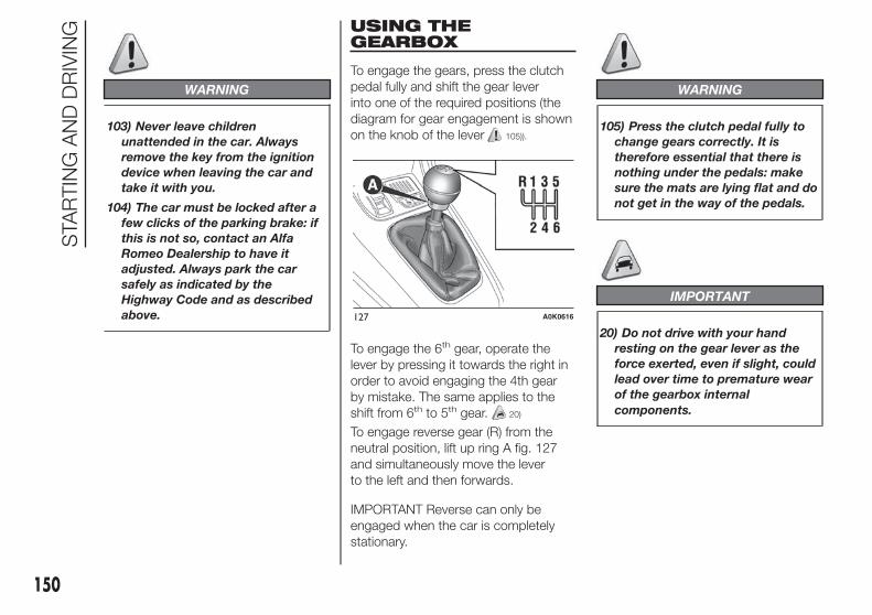
WARNING
103) Never leave children
unattended in the car. Always
remove the key from the ignition
device when leaving the car and
take it with you.
104) The car must be locked after a
few clicks of the parking brake: if
this is not so, contact an Alfa
Romeo Dealership to have it
adjusted. Always park the car
safely as indicated by the
Highway Code and as described
above.
USING THEGEARBOX
To engage the gears, press the clutch
pedal fully and shift the gear lever
into one of the required positions (the
diagram for gear engagement is shown
on the knob of the lever 105)).
To engage the 6th gear, operate the
lever by pressing it towards the right in
order to avoid engaging the 4th gear
by mistake. The same applies to the
shift from 6th to 5th gear. 20)
To engage reverse gear (R) from the
neutral position, lift up ring A fig. 127
and simultaneously move the lever
to the left and then forwards.
IMPORTANT Reverse can only be
engaged when the car is completely
stationary.
WARNING
105) Press the clutch pedal fully to
change gears correctly. It is
therefore essential that there is
nothing under the pedals: make
sure the mats are lying flat and do
not get in the way of the pedals.
IMPORTANT
20) Do not drive with your hand
resting on the gear lever as the
force exerted, even if slight, could
lead over time to premature wear
of the gearbox internal
components.
127 A0K0616
150
STA
RTIN
GA
ND
DR
IVIN
G

ALFA TCT
(for versions/markets, where provided)
IN BRIEF
The car can be equipped with an
electronically managed Alfa TCT
6-speed automatic transmission
where gearshifting takes place
automatically according to the
instantaneous car usage parameters
(car speed, road gradient and
accelerator pedal position).
The new transmission is an absolute
innovation as it matches the
Start&Stop system with the most
recent alternative to traditional
automatic transmissions with built-in
torque converter.
Manual gearshifting can still occur
thanks to the sequential mode
position of the gear lever.
SELECTOR LEVER
The lever fig. 128 (left hand drive
versions) or fig. 129 (right hand drive
versions), can be placed in the following
positions:
❒ P = Park
❒ R = Reverse
❒ N = Neutral
❒ D = Drive, (automatic forward speed)
❒ + = Sequential upshifting
❒ − = Sequential downshifting
If the lever is used in sequential mode,
moving the latter from D to the left,
the positions towards + or – are
unstable.
The lever has a button A, which must
be pressed to move the lever to P or R.
DISPLAY
The display can show the following:
❒ in automatic driving mode, the
gear selected (P, R, N, D). With
lever in position D (Drive), the display
will show D and the gear engaged
(e.g. D3 - see fig. 130).
❒ in sequential driving mode, the
manual engagement of a (higher
or lower) gear, with the relevant
number fig. 131;
128 - Left hand drive versions A0K0617
129 - Right hand drive versions A0K0618
130 A0K1540
131 A0K1541
151

POSITIONS OF THELEVER
Park (P)
Position P corresponds to the neutral
position of the transmission and locks
drive wheels mechanically.
It should only be engaged with the car
stationary and the handbrake should be
applied, if necessary.
With the ignition key at MAR-ON or with
engine running, or when the engine
switches off, if the gear lever is not
correctly positioned in P, letter P starts
flashing on the gear lever trim.
In this case, move the lever correctly to
position P. 21)
The ignition key can be removed only
when the lever is in position P. Moving
the lever from P to D must be
performed only when the car is
stationary and the engine at idling
speed.
Shifting from P to any other position of
the selector lever, with ignition key in
MAR-ON position, must be made
pressing the brake pedal and using the
button on the gear lever (see paragraph
"Selector lever").
If the battery is flat, to release the lever
you need to remove the gaiter and
operate the lever A fig. 132.
IMPORTANT NEVER leave the car
before having positioned the selector
lever in P.
Reverse (R)
The engine cannot be started with the
lever in position R.
Shifting from R to N or D is free, while
shifting from R to P can be made by the
button on the gear lever, with engine
at idling speed. 22)
Neutral (N)
It corresponds to neutral for a standard
manual gearbox. The engine can be
started with the lever in position N.
Engage N in case of prolonged stops.
To move the lever from position N,
release the accelerator and make sure
the engine is stable at idling speed.
Shifting from N to D is free, while
shifting from N to R or P can only be
made by the button on the gear lever.
Drive (D) - Automaticforward gear
It is the lever position in standard
running conditions.
Shifting from D to N is free, while
shifting from D to R or P can only be
made by the button on the gear lever.
Sequential mode (+ / –)
Shifting the lever from position D on
side in stable position, the transmission
is used in sequential mode.
Shifting the lever in unstable position (+
or −) gears are changed.
Important information
IMPORTANT All movements of the gear
lever must be performed with car
stationary and engine idling only.
The drive wheels are mechanically
locked in position P.
Shifting from P to R is possible with
brake pedal pressed and button on
gear lever pressed.
Shifting from R to N and from N to D is
free.
132 A0K0619
152
STA
RTIN
GA
ND
DR
IVIN
G

Shifting from D to "Sequential mode" is
free.
Shifting from "Sequential mode" to D is
free.
Shifting from D to N is free.
Shifting from N to R is possible only
with button on gear lever pressed.
Shifting from R to P is possible only
with button on gear lever pressed.
STARTING THE ENGINE
Starting is only permitted with gear
lever in position P or N (with or without
brake pedal pressed).
On starting, the system is at N or P (the
latter means neutral, but with the car’s
wheels locked mechanically).
Start&Stop system
With car at a standstill and Start&Stop
system activated, the engine switches
off if the gear lever is in a position
other than R.
The Start&Stop system does not
operate when the gear lever is in R, for
making parking manoeuvres easier.
In the event of stops uphill, the engine
switching off is disabled to activate
the "Hill Holder" function (works only
with running engine).
The engine restarts automatically if:
❒ the brake pedal is released (and the
lever is not at N or P)
❒ the lever is shifted to an unstable
position: +, − or R
❒ the lever is shifted from D to the left
in "Sequential mode"
❒ by the "+" or "–" paddles on the
steering wheel (for versions/markets,
where provided)
During the engine stop and start
sequence, the system passes through
the automatic engagement of neutral:
the display shows N.
IMPORTANT In some conditions (for
example with small gradients and brake
pedal not fully depressed), engine
switching off is not deactivated. In this
case, fully depress the brake pedal
to make the "Hill Holder" function
available and restart the engine, using
the gear lever or the paddles on the
steering wheel (for versions/markets,
where provided) as described
previously.
ENGINE SWITCHING OFF
Engine can be switched off in any
position of the gear lever.
Versions withStart&Stop system
To switch the engine off, you need to
stop the car by pressing the brake
pedal properly; if the pressure is not
enough, the engine will not be switched
off.
This feature can be exploited so that
the engine does not switch off in
particular traffic conditions.
Ignition key removal
The ignition key can be removed only if
the gear lever is in position P:
❒ if the engine is switched off with the
gear lever in position P: the ignition
key can be removed within 30
seconds;
❒ if the engine is switched off with the
gear lever in a position other than P:
the P letter on the display and on
the gear lever trim flashes for 5
seconds and an acoustic signal will
be emitted at the same time. Move
the lever to P within 5 seconds; then
it will be possible to remove the
ignition key for about 30 seconds.
153

In both cases, if the described
conditions and times are not respected,
the ignition key will be automatically
locked.
To remove the key, turn it to MAR-ON
and then to STOP.
IMPORTANT If the battery is flat and the
ignition key is engaged, the latter is
locked in position. To remove the key
manually, pull up the handbrake and
insert the screwdriver supplied in the
hole under the dashboard fig. 133
pressing slightly, until the key is
removed.
MOVING THE CAR
To move the car, from P press the
brake pedal and, using the button on
the gear lever, move the lever to the
desired position (D, R or "Sequential
mode").
The display will show the gear
engaged.
When the brake pedal is released, the
car starts moving forwards or
backwards, as soon as the manoeuvre
is activated ("creeping" effect). The
accelerator should not be pressed in
this case.
IMPORTANT The inconsistency
between the speed actually engaged
(shown on the display) and the position
of the gear lever is indicated by the
letter corresponding to the position of
the lever flashing on the trim (also
accompanied by an acoustic signal).
This condition should not be interpreted
as an operational fault, but simply as a
request by the system to repeat the
manoeuvre.
IMPORTANT With engine running and
car stationary, in "Sequential mode",
the request for engaging 2nd gear is not
accepted by the system (whether the
brake pedal is pressed or not).
If, with 1st gear or reverse (R) engaged,
the following conditions occur:
❒ road slope over 5%;
❒ clutch overheated;
❒ engine torque constant for a given
period (e.g. if the car hits the
pavement or is parked downhill/
uphill);
car movement is achieved by pressing
the accelerator pedal.
IMPORTANT With handbrake released
and brake pedal released, engine at
idling speed and gear lever in position
D, R or sequential, pay the utmost care
because the car can move even
without the operation of the accelerator
pedal. This condition can be used
with the car on a level surface during
tight parking manoeuvres using the
brake pedal only.
AUTOMATIC DRIVINGMODE
D can be selected from sequential
operation in any driving conditions.
In automatic driving mode, the best
ratio is selected by the electronic
transmission control unit depending on
speed, engine load (accelerator pedal
position) and gradient of the road.
133 A0K0254
154
STA
RTIN
GA
ND
DR
IVIN
G

“Kick-Down” function
To resume speed quickly, when the
accelerator pedal is pressed fully, the
transmission control system downshifts
("Kick-down" function).
IMPORTANT When driving on roads
with poor grip conditions (snow, ice,
etc.) avoid activating the kick-down
function.
Integration with "AlfaDNA" system
Operating the “Alfa DNA” system fig.
134, three different driving modes can
be selected:
❒ “Dynamic”: gear changes at higher
engine speeds. It enhances sporty
driving;
❒ “Natural”: gear changes at low
engine speeds. It enhances comfort
and reduces consumption;
❒ “All Weather”: driving programme on
roads with poor grip (e.g. snow, ice,
mud, etc.).
Gearshifting suggestion
With the transmission in automatic
mode (selector lever in position D),
when gearshifting is required by the
paddles on the steering wheel (for
versions/markets, where provided), the
system shifts to "Sequential mode",
with relevant displaying of the gear
engaged, for about 5 second.
When this time has elapsed, if the
paddles are not operated anymore, the
system goes back to the automatic
mode (D), with following displaying.
SEQUENTIAL DRIVINGMODE
In sequential driving mode, the
transmission works like a manual
gearbox.
Gearshifting throughgear lever
Move the lever sideways (to the left)
from position D to the sequential
position:
❒ lever towards "+": engage higher
gear;
❒ lever towards "−": engage lower gear.
The lever correct position in "Sequential
mode" is signalled when the symbols
"+" and "−" switch on and the symbol D
switches off on the display (the gear
engaged only is shown on the display).
Gearshifting throughsteering wheel paddles(for versions/markets, where provided)
On some versions, the steering wheel
paddles can be used to change gear
fig. 135. 106)
134 A0K0612
135 A0K0266
155

To use the paddles on the steering
wheel, the gear lever must be in
"Sequential mode" or in D:
❒ steering wheel paddle "+" (pulling
paddle towards driver fig. 136):
engage higher gear;
❒ steering wheel paddle "-" (pulling
paddle towards driver fig. 136):
engage lower gear.
The engagement of a lower or higher
gear is only permitted if the engine revs
allow it.
If the car is stopped with a higher gear
than 1st engaged, the transmission
will automatically engage 1st gear.
"Launch Control"Function
The "Launch Control" strategy permits
high-performance starting.
With the car stationary, proceed as
follows to activate this function:
❒ operate the “Alfa DNA” system and
activate the "Dynamic" driving mode;
❒ depress the brake pedal with your left
foot and, simultaneously, fully
depress the accelerator pedal with
your right foot;
❒ release the brake pedal: in this way a
more "lively" start is achieved.
When the brake pedal is released, the
car will start with maximum
acceleration. Despite the "Sequential
mode", the car will autonomously shift
the gear to guarantee max.
acceleration, once the correct shifting
speed has been reached.
108)
To abandon the strategy, simply
interrupt the above sequence
of operations or release the accelerator
pedal.
ACOUSTIC SIGNAL
For safety reasons, an acoustic signal is
heard when:
❒ the driver's side door is opened with
engine running and the gear lever is
in a position other than P;
❒ engine is switched off with gear lever
in a position other than P.
With the car stationary, the engine
started and (1st), (D) or (R) gear
engaged, the system activates the
acoustic signal and automatically
places the transmission in neutral (N)
when:
❒ the accelerator and/or brake pedals
are not pressed for at least 3 minutes
with creeping deactivated (for
example with handbrake engaged);
136 A0K0269
137 A0K0271
156
STA
RTIN
GA
ND
DR
IVIN
G
❒ shift gear using the gear lever or the
steering wheel paddle "−" (pulling
the paddle towards the driver as
previously described): rpm are thus
increased from 2750 to 4500; (1.4
Petrol versions) and from 1700 to
2700 (2.0 JTDM versions);

❒ the brake pedal is pressed for longer
than 10 minutes;
❒ the driver's door is opened with
creeping deactivated (for example
with handbrake engaged) without
pressing brake and/or accelerator
pedals;
❒ a fault has been detected in the
transmission.
IMPORTANT Shifting to neutral (N) -
operated by the system - involves
a situation of inconsistency between
gear lever position and gear engaged.
The manoeuvre is accompanied by
an acoustic inconsistency signal. This
acoustic signal continues until the gear
lever is placed in P or N, to restore
the correct transmission operation
conditions.
PARKING THE CAR
To park safely, with the brake pedal
pressed, P must be engaged and, in
case of parking uphills/downhills, the
handbrake must be engaged.
Before releasing the brake pedal, wait
until P appears on the display.
IMPORTANT NEVER leave the car
before having positioned the lever in P.
TOWING THE CAR
Make sure that the transmission is in
neutral (N), checking that the car moves
when pushed, and proceed in the
same way as for towing a normal car
with a manual gearbox.
IMPORTANT If the transmission cannot
be put in neutral (N), do not tow the
car and contact an Alfa Romeo
Dealership. Should the lever be in P,
release it before towing (see paragraph
"Positions of the lever").
IMPORTANTINFORMATION
With car stationary and gear engaged,
always keep the brake pedal pressed
until you decide to set off, then release
the brake and accelerate gradually.
During prolonged stops with the engine
running, it is advisable to keep the
transmission in neutral (N).
To protect the clutch, never use the
accelerator to keep the car stationary
(for example when stopped uphills/
downhills): clutch overheating could
damage it. Use the brake pedal instead
or the handbrake and only press the
accelerator pedal when you wish to set
off.
If reverse (R) is engaged, only engage
the 1st gear (or vice versa) when the car
is completely stopped.
Although it is highly inadvisable, if you
are driving downhill and, for unexpected
reasons, you let the car move forward
with the transmission in neutral (N),
when there is a request to engage
a gear, depending on the speed of the
car, the system will automatically
engage the best gear for the correct
transmission of drive torque to the
wheels. 107)
IMPORTANT
21) If the car is on a gradient, always
pull the handbrake BEFORE
placing the gear lever in P.
22) Engage reverse only with the car
stationary, engine at idling speed
and accelerator fully released.
157

WARNING
106) Using the levers incorrectly
(levers pushed towards the
dashboard, see fig. 137) could
break them.
107) Never leave children
unattended in the car. Always
remove the ignition key when
leaving the car and take the key
with you.
108) The Launch control function is
only available in Dynamic mode.
Regardless of what is explicitly
indicated in the description of
these modes, the ESC and ASR
systems are deactivated during
operation of the Launch Control
function. This means that vehicle
dynamic control is the sole
responsibility of the driver.
Therefore pay the utmost
attention when using the Launch
Control. Take into account traffic
and road surface conditions and
during manoeuvres make sure
there is enough room in the area
concerned.
SAVING FUEL
Here are some suggestions which can
help you to save fuel and lower harmful
emissions.
GENERALCONSIDERATIONS
Car maintenance
Checks and adjustments should be
carried out in accordance with the
“Scheduled Servicing Plan” (see
chapter “Maintenance and care”).
Tyres
Check the tyre pressures at least once
every four weeks: if the pressure is
too low, consumption levels increase as
resistance to rolling is higher.
Unnecessary loads
Do not travel with an overloaded boot.
The weight of the car and its
arrangement greatly affect fuel
consumption and stability.
Roof rack/ski rack
Remove the roof rack or the ski rack
from the roof after use. These
accessories lower aerodynamic
penetration and adversely affect
consumption levels. When transporting
particularly large objects, use a trailer
if possible.
Electrical devices
Use the electrical devices only for the
necessary amount of time. The heated
rear window, additional headlights,
screen wipers and heater fan require a
considerable amount of energy;
increasing the current uptake increases
fuel consumption (by up to +25% in
an urban cycle).
Climate control system
Using the climate control system will
increase consumption: use the air vents
when the temperature outside permits.
Devices foraerodynamic control
The use of non-certified devices for
aerodynamic control may adversely
affect air drag and fuel consumption.
158
STA
RTIN
GA
ND
DR
IVIN
G

DRIVING STYLE
Starting
Do not warm up the engine at low or
high revs when the car is stationary;
this causes the engine to warm up
more slowly, thereby increasing fuel
consumption and emissions. It is
therefore advisable to move off
immediately, slowly, avoiding high
speeds: in this way the engine will
warm up more quickly.
Unnecessary actions
Avoid accelerating when stopped at
traffic lights or before switching off the
engine. The latter action, as well as
double-declutching, is unnecessary and
causes increased fuel consumption
and pollution.
Gear selection
Use a high gear when traffic and road
conditions allow it. Using a low gear for
faster acceleration will increase fuel
consumption. In the same way
improper use of a high gear increases
consumption, emissions and engine
wear.
Maximum speed
Fuel consumption considerably
increases as speed increases. Maintain
a constant speed, avoiding
unnecessary braking and acceleration,
which cost in terms of both fuel
consumption and emissions.
Acceleration
Accelerating violently severely affects
consumption and emissions:
acceleration should be gradual and
should not exceed the maximum
torque.
CONDITIONS OF USE
Cold starting
Short distances and frequent cold
start-ups will prevent the engine from
reaching optimal running temperature.
This results in a significant increase
in consumption levels (from +15 to
+30% on the urban cycle) and
emissions.
Traffic and roadconditions
High fuel consumption is caused by
heavy traffic, for instance when
travelling in a queue with frequent use
of low gears or in large towns with
many traffic lights. Winding mountain
roads and rough road surfaces also
adversely affect consumption.
Stops in traffic
During prolonged hold-ups (e.g. level
crossings) switch off the engine.
159

TOWING TRAILERS
IMPORTANT
The vehicle must be provided with a
type-approved tow hook and adequate
electrical system to tow caravans or
trailers. Installation must be carried out
by a specialist.
Fit any specific and/or additional rear
view mirrors as specified by the
Highway Code.
Remember that when towing a trailer,
steep hills are harder to climb, the
braking spaces increase and overtaking
takes longer depending on the overall
weight.
Engage a low gear when driving
downhill, rather than constantly using
the brake.
The weight of the trailer reduces the
load capacity of the car by the same
amount. Consider the weight at full
load, including accessories and
luggage, to make sure you do not
exceed the maximum towable weight
(shown in the registration document).
Do not exceed the speed limits specific
to each country you are driving in, in
the case of vehicles towing trailers.
In any case do not exceed 100 km/h.
INSTALLING A TOWHOOK
Contact an Alfa Romeo Dealership to
install a tow hook. 109) 110)
WARNING
109) The ABS with which the car is
equipped will not control the
braking system of the trailer.
Particular caution is therefore
required when travelling on
slippery roads.
110) Never modify the braking
system of the car to control the
trailer brake. The trailer braking
system must be fully independent
from the hydraulic system of the
car.
SNOW TYRES
Use snow tyres of the same size as the
normal tyres provided with the car:
the Alfa Romeo Dealership will be able
to advise you on the most appropriate
tyre to use.
Only use these tyres in the event of ice
or snow on the roads. 111)
For the type of tyre to be used, inflation
pressures and the specifications of
snow tyres, follow the instructions given
in the "Wheels" paragraph in the
"Technical specifications" chapter.
The winter performance of these tyres
is considerably reduced when the tread
thickness is less than 4 mm. Replace
them in this case.
Due to the specific characteristics of
snow tyres, in normal weather
conditions or on long motorway
journeys, the performance of these
tyres is lower than that of standard
tyres. Their usage should therefore be
restricted in accordance with their
type approval.
All four tyres should be the same (brand
and track) to ensure greater safety
when driving and braking as well as
making the car more responsive. It is
inadvisable to change the rotation
direction of tyres.
160
STA
RTIN
GA
ND
DR
IVIN
G

WARNING
111) The maximum speed for snow
tyres marked “Q” is 160 km/h,
while it is 190 km/h for “T” tyres
and 210 km/h for "H" tyres. The
highway code speed limits must
however always be complied with.
SNOW CHAINS
The use of snow chains should be in
compliance with local regulations.
Snow chains can be fitted to the tyres
of the front wheels (drive wheels) only.
Check the tension of the snow chains
after the first few metres have been
driven.
Use low-clearance snow chains: on all
versions, for 195/55 R16", 205/55 R16"
and 225/45 R17" size tyres use
low-clearance snow chains with a
maximum projection beyond the tyre
profile of 9 mm. 23)
IMPORTANT The space-saver wheel
cannot be fitted with snow chains. If a
front (drive) wheel is punctured and
snow chains must be used, you must
remove a normal wheel from the rear
axle and replace it with the space-saver
wheel. In this way, with two normal
drive wheels, it is possible to use snow
chains.
IMPORTANT
23) Keep your speed down when
snow chains are fitted; do not
exceed 50 km/h. Avoid potholes,
steps and pavements and avoid
driving for long distances on
roads not covered with snow to
prevent damaging the car and the
road surface.
161

STORING THE CAR
If the car is to be left inactive for longer
than a month, the following precautions
should be noted:
❒ park the car in covered, dry and if
possible well-ventilated premises and
slightly open the windows;
❒ check that the handbrake is not
engaged;
❒ disconnect the negative battery
terminal and check the battery
charge. Repeat this check once
every three months during storage;
❒ if the battery is not disconnected
from the electrical system, checks its
state of charge every thirty days;
❒ clean and protect the painted parts
using protective wax;
❒ clean and protect the shiny metal
parts using special compounds
available commercially;
❒ sprinkle talcum powder on the
windscreen and rear window wiper
rubber blades and lift them off the
glasses;
❒ slightly open the windows;
❒ cover the car with a cloth or
perforated plastic sheet. Do not use
compact plastic sheets which do
not allow humidity to evaporate from
the surface of the car.
❒ inflate tyres to +0.5 bar above the
standard prescribed pressure and
check it periodically;
❒ do not drain the engine cooling
system;
❒ Any time the car is left inactive for
two weeks or more, operate the
air conditioning system with engine
idling for at least 5 minutes, setting
external air and with fan at maximum
speed. This operation will ensure a
suitable lubrication to minimise
possibility of damage to the
compressor when the system is
operated again.
IMPORTANT After turning the ignition
key to STOP, wait at least 1 minute
before disconnecting the electrical
supply to the battery.
162
STA
RTIN
GA
ND
DR
IVIN
G

IN AN EMERGENCY
A punctured tyre or a burnt-out bulb?
At times, a problem may interferewith our journey.
The pages on emergencies can helpyou to deal with critical situationsindependently and with calm.
In an emergency we recommend thatyou call the freephone number found inthe Warranty Booklet.
It is also possible to call the 00 8002532 4200 freephone number tosearch the nearest Alfa RomeoAuthorised Network.
STARTING THE ENGINE .................164
REPLACING A WHEEL ...................165
"FIX&GO AUTOMATIC" KIT .............170
CHANGING A BULB .......................173
REPLACING EXTERIOR BULBS......177
INTERIOR BULB REPLACEMENT...180
REPLACING FUSES........................181
BATTERY RECHARGING ................191
RAISING THE CAR..........................192
TOWING THE CAR .........................192
163

STARTING THEENGINE
Contact the Alfa Romeo Dealership
immediately if the warning light
stays on constantly on the
instrument panel.
JUMP STARTING
If the battery is flat, start the engine
using an auxiliary battery with the same
capacity or a little higher than the flat
one. 24) 25) 112)
Proceed as follows to start the car:
❒ connect the positive terminal (+) fig.
138 of the auxiliary battery only to
the point indicated on the car battery
(writing OK) and nowhere else;
❒ with a second lead, connect the
negative terminal ( − ) of the auxiliary
battery to an earthing point on
the engine or the gearbox/
transmission of the car to be started;
❒ start the engine; when the engine has
been started, remove the leads
reversing the order above.
For versions with Start&Stop system, in
case of starting by auxiliary battery,
refer to the paragraph “Start&Stop
system” in the chapter “Getting to know
your car”.
If after a few attempts the engine does
not start, contact the Alfa Romeo
Dealership.
BUMP STARTING
Never jump start the engine by pushing,
towing or coasting downhill.
IMPORTANT
24) Do not connect the negative
terminals of the two batteries
directly! If the auxiliary battery is
installed on another car, prevent
accidental contact between
metallic parts of the two cars.
25) Never use a fast battery charger
to start the engine as this could
damage the electronic systems
and the ignition and engine fuel
supply control units.
WARNING
112) This procedure must be
performed by qualified personnel
as incorrect actions may cause
high-intensity electrical discharge.
Furthermore, battery fluid is
poisonous and corrosive: avoid
contact with skin and eyes. Keep
naked flames away from the
battery. No smoking. Do not cause
sparks.
138 A0K0247
164
INA
NE
ME
RG
EN
CY

REPLACING AWHEEL
GENERALINSTRUCTIONS
The car is equipped with the “Fix&Go
Automatic Kit”: see the paragraph
“Fix&Go Automatic Kit” for how to use
this device.
As an alternative to the “Fix&Go
Automatic Kit” the car may be
requested with a space-saver wheel:
see the instructions on the following
pages for changing the wheel.
113) 114) 115) 116) 117)
JACK
Please note that:
❒ the jack weight is 1.76 kg;
❒ the jack requires no adjustment;
❒ the jack cannot be repaired and in
the event of a fault it must be
replaced by another original one;
❒ no tool other than its cranking device
may be fitted on the jack.
To change a wheel, proceed as follows:
❒ stop the car in a position that is not
dangerous for oncoming traffic
where you can change the wheel
safely. The ground should be flat
if possible, and sufficiently firm;
❒ switch off the engine, pull up the
handbrake and engage the 1st gear
or reverse. Wear the reflective safety
jacket (compulsory by law) before
getting out of the car;
❒ open the luggage compartment, pull
tab A fig. 139 and lift up the mat;
❒ using wrench A fig. 140 positioned in
the tool box, loosen the locking
device, take the tool box B and place
it close to the wheel to be replaced,
then take the space-saver wheel C;
❒ take the wrench A fig. 141 and
loosen the fixing bolts by about one
turn. For versions with alloy rims,
shake the car to facilitate detachment
of the rim from the wheel hub.
❒ position the jack under the car, near
the wheel to be changed. On
versions where this is fitted, be
careful not to damage the plastic
aerodynamic guard;
139 A0K0648
140 A0K0649
141 A0K0650
165

❒ operate the device A fig. 142 so as to
extend the jack, until the upper part
B fig. 143 is inserted correctly inside
the side member C;
❒ alert any bystander that the car is
about to be raised; all persons
should be kept away from the car
and nobody must touch it until it has
been lowered;
❒ fit handle D into the housing in device
A, operate the jack and raise the car
until the wheel is a few centimetres
from the ground;
❒ for versions with wheel cap, remove
the wheel cap after loosening the 4
fastening bolts and finally loosen
the fifth bolt and extract the wheel;
❒ make sure the contact surfaces
between space-saver wheel and hub
are clean so that the fastening bolts
will not come loose;
❒ fit the space-saver wheel by inserting
the first bolt for two threads into the
hole closest to the valve;
❒ take the wrench A fig. 140 and fully
tighten the fixing bolts;
❒ operate the jack handle D to lower
the car. Then extract the jack;
❒ use the wrench A provided to fully
tighten the bolts in a criss-cross
fashion as per the numerical
sequence illustrated in fig. 144;
❒ when replacing an alloy wheel it is
advisable to place it upside down,
with the aesthetic part facing
upwards.
Restore the standard wheel as soon as
possible, because, once placed in the
associated compartment, the luggage
compartment load platform is rendered
uneven as the standard wheel is larger
than the spare wheel. 26)
REMOVING THESUBWOOFER (versionswith Bose HI-FI system)(for versions/markets, where provided)
IMPORTANT The following procedure
only applies to cars equipped with
Bose HI-FI systems with subwoofer (for
versions/markets, where provided).
142 A0K0651
143 A0K0652
144 A0K0040
166
INA
NE
ME
RG
EN
CY

Subwoofer and space-saver spare wheel
On these versions, the tools needed for
changing the wheel are arranged in a
specific container on the left-hand side
of the luggage compartment (see fig.
145).
The jack is located in a pocket, again
on the left-hand side of the luggage
compartment (see fig. 146).
Proceed as follows to remove the
subwoofer:
❒ open the luggage compartment, pull
tab A fig. 147, lift the mat upwards
and remove the load compartment
shim;
❒ loosen the fastening device A,
remove the clip B fastening the cable
and then lift the subwoofer;
❒ rest the subwoofer on the side of the
luggage compartment and take the
space-saver wheel;
❒ replace the wheel as described
previously.
At the end of the operation:
❒ reposition the subwoofer correctly
(see indications on the label applied
over the subwoofer itself), so that the
word “BOSE” is positioned in the
right direction for reading;
❒ reposition the subwoofer wire
correctly to avoid pinching it. Then
fasten the clip B and fasten the
blocking device A. Finally, position
the load compartment shim correctly
and lower the luggage compartment
mat.
❒ reposition the subwoofer correctly
(see indications on the label applied
over the subwoofer itself), so that the
word “BOSE” is positioned in the
right direction for reading;
❒ reposition the subwoofer wire
correctly to avoid pinching it. Then
fasten the clip B and fasten the
blocking device A. Finally, position
the load compartment shim fig. 145
correctly and lower the luggage
compartment mat.
Subwoofer and "Fix&GoAutomatic Kit"
Locating the Automatic Fix&Go Kit:
❒ open the luggage compartment, pull
tab A and lift the mat;
❒ take the “Fix&Go Automatic Kit”
located on the left side of the luggage
compartment (see fig. 148);
❒ inflate the wheel (see paragraph
entitled “Fix&Go Automatic Kit”).
145 A0K0235
146 A0K0228
147 A0K0654
167

IMPORTANT If you need to remove the
subwoofer, follow the indications shown
on the adhesive label fig. 148 over the
subwoofer itself to reposition it
correctly.
REFITTING THE WHEEL
Following the procedure described
previously, raise the car and remove the
space-saver wheel.
Proceed as follows:
❒ make sure the contact surfaces
between standard wheel and hub are
clean so that the fastening bolts will
not come loose;
❒ for versions with steel rims: fix the
hub cap on the rim, aligning the
crescent hole with the bolt you have
fitted, then insert the other 4 bolts;
❒ tighten the retaining bolts using
wrench A fig. 139;
❒ lower the car and remove the jack;
❒ use wrench A to fully tighten the
bolts, following the sequence
illustrated in fig. 144
At the end of operation
Proceed as follows:
❒ stow the space-saver wheel in the
compartment provided in the luggage
compartment;
❒ insert the jack and the other tools in
the container;
❒ arrange the container and tools on
the space-saver wheel;
❒ correctly reposition the luggage
compartment mat.
WARNING
113) The space-saver wheel is
specific for your car. Do not use it
on cars of different models. Do
not use space-saver wheels of
different models on your car. The
space-saver wheel must only be
used in the event of emergency. It
must only be used for the
distance necessary to reach a
service point and the car speed
must not exceed 80 km/h. The
space-saver wheel has an orange
label that summarises the main
cautions for use and limitations.
Never remove or cover the label.
Never apply any hub cap to the
space-saver wheel.
114) Use your hazard lights, warning
triangle, etc to show that your car
is stationary. Passengers should
get out of the car, particularly if it
is heavily loaded, and wait for
the wheel to be changed away
from the traffic. In the event of a
wheel change on a slope or on
unsurfaced roads, chock the
wheels.
148 A0K0178
168
INA
NE
ME
RG
EN
CY

115) Car handling is modified with
the space-saver wheel fitted.
Avoid violent acceleration and
braking, abrupt steering and fast
cornering. The overall duration
of the space-saver wheel is of
about 3000 km, after which the
relevant tyre must be replaced
with another one of the same
type. Never install a traditional
tyre on a rim designed to be used
as a space-saver wheel. Have
the wheel repaired and refitted as
soon as possible. Using two or
more space-saver wheels at the
same time is forbidden. Do not
grease the bolt threads before you
fit them, because they could
suddenly come loose.
116) Use the jack only to replace
wheels on the car with which it
is supplied or on other cars of the
same model. Never use the jack
for other purposes, such as lifting
other car models. Never use it
for repair operations under the
car. Incorrect positioning of the
jack may cause the car to fall. Do
not use the jack for loads higher
than those shown on the label.
Never install snow chains on the
space-saver wheel; if a front tyre
(driving wheel) is punctured and
you need to use snow chains, use
a standard wheel from the rear
axle and install the space-saver
wheel on the rear axle. In this
way, with two normal front drive
wheels, it is possible to use snow
chains.
117) Incorrect hub cap assembly
may cause it to come off when the
car is moving. Never tamper with
the inflation valve. Never
introduce tools of any kind
between rim and tyre. Regularly
check the inflation pressure of the
tyres and space-saver wheel
(see chapter "Technical
specifications").
IMPORTANT
26) Contact an Alfa Romeo
Dealership as soon as possible to
have the correct tightening of
the wheel bolts checked.
169

"Fix&Go Automatic"kit
This is located in the luggage
compartment (the kit container may
vary according to version - see fig.
149).
The kit also contains a screwdriver and
a tow hook.
The kit also contains:
❒ bottle A fig. 150 containing sealant
and fitted with: filling tube B and
adhesive label C with the wording
“max. 80 km/h” to be placed in
a clearly visible position (e.g. on the
dashboard) after repairing the tyre;
❒ a compressor D complete with
pressure gauge and connectors;
❒ an information leaflet fig. 151,
providing instructions for using the kit
correctly. This booklet should be
given to the persons charged with
handling the tyre treated with this kit;
❒ a pair of gloves located in the side
compartment of the compressor;
❒ adapters for inflating different
elements.
2)
118) 119) 121)
IMPORTANT The sealing liquid is
suitable for use at temperatures in the
range from –20°C to +50°C. The
sealant has an expiry date.
INFLATION PROCEDURE
120) 122) 123) 124) 125) 126)
Proceed as follows:
❒ engage the handbrake, unscrew the
tyre valve cap, take out filler hose A
fig. 152 and tighten ring nut B on the
tyre valve;
❒ make sure that switch A for the
compressor is in position 0 (off), start
the engine, insert the plug into the
luggage compartment power socket
(see fig. 154) or on central tunnel
(see fig. 155) and switch on the
compressor by bringing switch A to
position I (on);
149 A0K0515
150 A0K0516
151 A0K0517
170
INA
NE
ME
RG
EN
CY

❒ inflate the tyre to the pressure
indicated in the “Wheels” paragraph
in the “Technical data” chapter. In
order to obtain a more precise
reading, check the pressure value on
pressure gauge B fig. 153 with the
compressor off;
❒ if after five minutes it is still impossible
to reach at least 1.8 bar, disengage
the compressor from the valve and
power socket, then move the car
forwards by approx. ten metres
in order to distribute the sealing fluid
inside the tyre evenly, then repeat
the inflation operation;
❒ if you still cannot obtain a pressure of
at least 1.8 bar within 5 minutes from
the compressor switching on, do
not drive off and contact an Alfa
Romeo Dealership;
❒ after having driven for about 10
minutes, stop and recheck the tyre
pressure; remember to engage
the handbrake;
❒ if a pressure value of at least 1.8 bar
is detected, restore the correct
pressure (with the engine running and
the handbrake engaged), resume
driving and drive with great care to an
Alfa Romeo Dealership.
CHECKING ANDRESTORING TYREPRESSURE
The compressor can also be used to
check and, if necessary, adjust the tyre
pressure.
Release quick coupling A fig. 157 and
connect it directly to the valve of the
tyre to be inflated.
152 A0K0518
153 A0K0519
154 A0K0520
155 A0K0128
156 A0K0521
171

REPLACING THE BOTTLE
Proceed as follows:
❒ release coupling A fig. 157 and
disconnect tube B;
❒ turn the bottle to be replaced
anticlockwise and raise it;
❒ fit the new bottle and turn it
clockwise;
❒ insert coupling A and tube B in
position.
IMPORTANT
27) In the event of a puncture
caused by foreign bodies, the kit
may be used to repair tyres
showing damages on the tread or
shoulder up to max. 4 mm
diameter.
IMPORTANT
2) Dispose of the bottle and the
sealant properly. Dispose of the
components in compliance with
national and local regulations.
WARNING
118) Give the booklet to the
technicians who will be handling
the tyre that was treated using
the "Fix&Go Automatic" kit.
119) Punctures on the sides of the
tyre may not be repaired. Do not
use the kit if the tyre is damaged
due to travelling when flat.
120) Wear the protective gloves
provided with the kit.
121) Apply the adhesive label where
it can be easily seen by the driver
as a reminder that the tyre has
been treated with the quick repair
kit. Drive carefully, particularly
on bends. Do not exceed 80 km/h.
Do not accelerate or brake
suddenly.
122) If the pressure has fallen below
1.8 bar, do not drive any further:
the Fix&Go Automatic kit cannot
guarantee proper hold because
the tyre is too damaged. Contact
Alfa Romeo Authorised Services.
157 A0K0041
172
INA
NE
ME
RG
EN
CY

123) Always indicate that the tyre
was repaired using the quick
tyre repair kit. Give the booklet to
the technicians who will be
handling the tyre that was treated
using the kit.
124) Repair is not possible if the
wheel rim is damaged (groove
is deformed, causing air to
escape). Do not remove foreign
bodies (screws or nails) from the
tyre.
125) Do not operate the compressor
for longer than 20 minutes
consecutively. Risk of
overheating. The kit is not suitable
for definitive repairs, so the
repaired tyres may only be used
temporarily.
126) The bottle contains ethylene
glycol and latex: it may cause
an allergic reaction. It is harmful if
swallowed. It is irritant for the
eyes. It may cause sensitisation if
inhaled or on contact. Avoid
contact with eyes, skin and
clothes. In the event of contact,
rinse immediately with plenty
of water. If ingested, do not
induce vomiting. Rinse out your
mouth, drink large quantities
of water and seek immediate
medical attention. Keep out of the
reach of children. The product
must not be used by asthmatics.
Do not inhale the vapours during
insertion and suction. Call a
doctor immediately if allergic
reactions are noted. Store the
bottle in its proper compartment,
away from sources of heat. The
sealant fluid has an expiry date.
Replace the bottle containing
out-of-date sealant fluid.
CHANGING A BULB
28)
127) 128) 129)
GENERALINSTRUCTIONS
❒ Before changing a bulb check the
contacts for oxidation;
❒ replace blown bulbs with others of
the same type and power;
❒ after replacing a headlight bulb,
always check its alignment;
❒ when a light is not working, check
that the corresponding fuse is intact
before changing the bulb. For the
location of fuses, refer to the
paragraph “If a fuse blows” in this
chapter.
173

IMPORTANT When the weather is cold
or damp or after heavy rain or washing,
the surface of headlights or rear lights,
may steam up and/or form drops of
condensation on the inside. This is
a natural phenomenon due to the
difference in temperature and humidity
between the inside and the outside
of the glass which does not indicate a
fault and does not compromise the
normal operation of lighting devices.
The mist disappears quickly when the
lights are turned on, starting from
the centre of the diffuser, extending
progressively towards the edges.
IMPORTANT
28) Halogen bulbs must be handled
by holding the metallic part only.
Touching the transparent part
of the bulb with your fingers may
reduce the intensity of the
emitted light and even reduce the
lifespan of the bulb. In the case
of accidental contact, rub the
lamp with a cloth and spirit and
leave to dry.
WARNING
127) Changes or repairs to the
electrical system carried out
incorrectly and without due
consideration for the technical
specifications of the system may
lead to malfunctioning and
generate a fire hazard.
128) Halogen bulbs contain
pressurised gas. If they break,
glass fragments could fly
everywhere.
129) Due to the high supply voltage,
gas discharge bulbs (Bi-Xenon)
should only be replaced by
specialised personnel: danger of
death! Contact an Alfa Romeo
Dealership.
174
INA
NE
ME
RG
EN
CY

TYPES OF BULBS
The car has the following light bulbs:
Glass bulbs: (type A) they are press-fitted. Pull to extract.
Bayonet-type bulbs: (type B) to remove from its holder, press
the bulb and turn it anti-clockwise, then extract it.
Tubular bulbs: (type C) release them from their contacts to
remove.
Halogen bulbs: (type D) to remove the bulb, release the clip
holding the bulb in place.
Halogen bulbs: (type E) to remove the bulb, release the clip
holding the bulb in place.
175

Bulbs Type Power Re. Figure
Front side lights/Daytime running lights (DRL) LED – –
Rear side lights LED – –
Dipped headlights H7 55W D
Main beam headlamps H1 55W E
Main/Dipped beams (versions with Bi-Xenon
headlights) (for versions/markets, where provided)F D1S -
Front direction indicators PY24W 24W B
Rear direction indicators R10W 10W B
Side direction indicators LED – –
Brake light LED – –
3rd brake light LED – –
Number plate light W5W 5W A
Fog lights H3 55W E
Rear fog lights H21W 21W B
Reversing lights P21W 21W B
Front roof light C10W 10W C
Luggage compartment roof light W5W 5W A
Glove compartment light C5W 5W C
176
INA
NE
ME
RG
EN
CY

REPLACINGEXTERIOR BULBS
FRONT LIGHT CLUSTERS
These contain the bulbs for the side
lights/daytime running lights (DRL),
dipped beams, main beams and
direction indicators. The bulbs are
arranged as follows fig. 158:
A Side lights/daytime running lights and
main beam headlights
B Dipped beam headlights
C Direction indicators
SIDE LIGHTS/DAYTIMERUNNING LIGHTS (DRL)
These are LEDs. For the replacement,
contact an Alfa Romeo Dealership.
MAIN BEAM HEADLIGHTS
To change the bulb, proceed as
follows:
❒ remove cover A fig. 158;
❒ remove the connector A fig. 159 and
then open the tabs B pulling
outwards;
❒ remove the bulb C and replace it;
❒ refit the new lamp, making sure that it
is locked correctly, secure the tabs B
again and reconnect the connector
A;
❒ then refit the cover A fig. 158.
DIPPED BEAMHEADLIGHTS
To change the bulb, proceed as follows:
❒ remove cover B fig. 158;
❒ remove the connector A fig. 160,
press the tab B forward and then
release by pushing it towards inside
the car;
❒ remove the bulb C and replace it;
❒ refit the new lamp, making sure that it
is locked correctly, secure the tab B
again and reconnect the connector
A;
❒ then refit the cover B fig. 158.
158 A0K0631
159 A0K0632
160 A0K0633
177

DIRECTION INDICATORS
Front
To change the bulb, proceed as follows:
❒ turn the cover C fig. 158
anticlockwise by ¼ of a turn;
❒ replace the bulb + bulb holder
assembly A fig. 161.
Side
These are LEDs. For the replacement,
contact an Alfa Romeo Dealership.
FOG LIGHTS(for versions/markets, where provided)
For replacing these bulbs, contact
an Alfa Romeo Dealership.
REAR LIGHT CLUSTERS
These contain the side lights, brake
lights, direction indicators (bulbs in fixed
light cluster), reverse light and rear fog
light (bulb in light cluster on boot hatch).
Removing the fixed lightcluster
Proceed as follows:
❒ open the boot and loosen the rear
light cluster fastening screw A fig.
162;
❒ extract the light cluster by removing it
with both hands in the direction
indicated by the arrows;
❒ disconnect the electrical connector
and replace the bulb concerned.
SIDE LIGHTS/BRAKELIGHTS
These are LEDs. For the replacement,
contact an Alfa Romeo Dealership.
DIRECTION INDICATORS
With the light cluster removed, to
replace the bulb undo the two screws A
fig. 163, remove the bulb holder and
replace bulb B.
REAR FOG LIGHTS/REVERSING LIGHTS
To replace the bulbs proceed as
follows:
❒ open the boot and remove the cover
A fig. 164 using a screwdriver in the
point indicated by an arrow;
161 A0K0634
162 A0K0635
163 A0K0636
178
INA
NE
ME
RG
EN
CY

❒ remove the connector A fig. 165 and
extract the bulb holder assembly by
operating on the retaining tab B
and then by loosening the screw C;
❒ remove the bulb by pushing it slightly
and turning it anticlockwise (D =
reverse light bulb; E = rear fog light
bulb);
❒ refit the bulb holder assembly
positioning it correctly, fasten screw
C and then fix it by means of the
retaining tab B. Reconnect connector
A then refit cover A fig. 164.
IMPORTANT Protect the tip of the
screwdriver with a cloth to prevent
scratching when removing the cover A.
3rd BRAKE LIGHTS
These are LED lights and are located
on the spoiler integrated with the
tailgate. For the replacement, contact
an Alfa Romeo Dealership.
NUMBER PLATE LIGHTS
To replace the bulbs proceed as
follows:
❒ remove the number plate light units A
fig. 166;
❒ turn the bulb holder B fig. 167
anticlockwise, extract the bulb C and
replace it.
164 A0K0637
165 A0K0638
166 A0K0639
167 A0K0640
179

INTERIOR BULBREPLACEMENT
FRONT ROOF LIGHT
To change the bulb, proceed as follows:
❒ remove roof light A fig. 168 working
at the points indicated by the arrows;
❒ undo the bulb housings B fig. 169
and remove them by extracting
outwards: then replace bulbs C;
❒ correctly fit the new bulbs in the
relevant housings B;
❒ fit roof light A fig. 168 in its housing
making sure it is locked.
REAR ROOF LIGHT
To change the bulb, proceed as follows:
❒ remove roof light A fig. 170 working
at the points indicated by the arrows;
❒ open protective flap B fig. 171 and
replace bulb C, releasing it from the
side contacts. Make sure that the
new bulb is correctly secured
between the contacts;
❒ close protective flap B again and fix
roof light A fig. 170 in its housing,
making sure that it is locked.
LUGGAGECOMPARTMENTCOURTESY LIGHT
To change the bulb, proceed as follows:
❒ open the luggage compartment and
extract courtesy light A fig. 172
working in the point shown by the
arrow;
❒ open protection B fig. 173 and
replace the bulb;
❒ refit protection B on the lens;
❒ refit courtesy light A fig. 172 by
inserting it in its correct position firstly
on one side and then pressing on
the other until it clicks into place.
168 A0K0806
169 A0K0807
170 A0K0643
171 A0K0644
180
INA
NE
ME
RG
EN
CY

GLOVE COMPARTMENTCOURTESY LIGHT
To change the bulb, proceed as follows:
❒ open the glove compartment and
extract courtesy light A fig. 174;
❒ open protection B and replace the
bulb;
❒ refit protection B on the lens;
❒ refit courtesy light A by inserting it in
its correct position firstly on one side
and then pressing on the other until
it clicks into place.
COURTESY LIGHT(for versions/markets, where provided)
For bulb replacement, contact an
Alfa Romeo Dealership.
REPLACING FUSES
GENERAL INFORMATION
Fuses protect the electrical system:
they intervene (blow) in the event of a
failure or improper intervention on
the system.
When a device does not work, check
the condition of its protection fuse: the
filament A fig. 175 must be intact. 29)
30)
If it is not, replace the blown fuse with
another having the same amperage
(same colour). 130) 131) 132) 133) 134)
B = undamaged fuse.
C = fuse with damaged filament.
172 A0K0645
173 A0K0646
174 A0K0647
175 A0K0523
181

VERSIONS WITH "ALFATCT" AUTOMATICTRANSMISSION(for versions/markets, where provided)
The Alfa TCT transmission components
are protected by specific fuses. Contact
an Alfa Romeo Dealership if a fuse
needs replacing.
176 A0K0524
182
INA
NE
ME
RG
EN
CY Use the pliers A fig. 176 under the
engine compartment junction unit lid to
remove the fuses (see “Engine
compartment junction unit” for how to
remove the lid).

FUSE LOCATION
Fuses are grouped together in three
fuse boxes located in the engine
compartment, dashboard and luggage
compartment.
Engine compartment fuse box
This is located next to the battery fig.
178: to access the fuses, undo screws
A fig. 177 and remove cover B.
The number identifying the electrical
component corresponding to each fuse
is on the back of the cover.
After replacing the fuse, make sure you
close cover B on the junction unit.
177 A0K0525
F10
F87
F85F86
F19F09
F21F88F20
178 A0K0231
183

Dashboard fuse box
To access the fuses fig. 180 insert a
hand in the housing A fig. 179 and
lower the flap B.
179 A0K0527
180 A0K0244
184
INA
NE
ME
RG
EN
CY

Luggage compartment fuse box
The fuse box (fig. 181) is located on the
left side of the luggage compartment
underneath the side cover.
For access, contact an Alfa Romeo
Dealership.
181 A0K0529
185
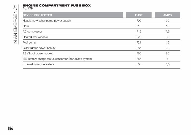
ENGINE COMPARTMENT FUSE BOXfig. 178
DEVICE PROTECTED FUSE AMPS
Headlamp washer pump power supply F09 30
Horn F10 15
AC compressor F19 7,5
Heated rear window F20 30
Fuel pump F21 15
Cigar lighter/power socket F85 20
12 V boot power socket F86 20
IBS Battery charge status sensor for Start&Stop system F87 5
External mirror defrosters F88 7,5
186
INA
NE
ME
RG
EN
CY

INSTRUMENT PANEL FUSE BOXfig. 180
DEVICE PROTECTED FUSE AMPS
Right main beam headlight F91 7,5
Left main beam headlight F90 7,5
Right dipped beam headlight (versions with halogen headlights) F12 7,5
Left dipped beam headlight (versions with halogen headlights) F13 7,5
Right dipped beam headlight (versions with Bi-Xenon headlights) F12 15
Left dipped beam headlight (versions with Bi-Xenon headlights) F13 15
Right fog light F93 7,5
Left fog light F92 7,5
Luggage compartment courtesy light/Sun visor courtesy light/Glove
compartment courtesy light/Front and rear roof lightsF32 10
Various devices F31 5
Rear electric window (left side) F33 20
Rear electric window (right side) F34 20
+30 F36 10
Various devices F37 7,5
Central locking F38 20
Body Computer supply F42 5
Two-way windscreen washer pump F43 20
Front electric window (driver side) F47 20
187

DEVICE PROTECTED FUSE AMPS
Front electric window (passenger side) F48 20
Various devices F49 5
Various devices F50 7.5
Various devices F51 5
+30 F53 7,5
188
INA
NE
ME
RG
EN
CY

LUGGAGE COMPARTMENT JUNCTION UNITfig. 181
DEVICE PROTECTED FUSE AMPS
Left front seat movement F1 15
Right front seat movement F2 15
Electric sun roof F3 15
Front seat heating F5 15
BOSE amplifier + Subwoofer F6 20
IMPORTANT
29) Never replace a blown fuse with metal wires or other material.
30) If it is necessary to wash the engine compartment, take care not to directly hit the junction unit and the window
wiper motors with the water jet.
189

134) Contact an Alfa Romeo Dealership if a safety system (airbags, brakes), power unit system (engine, gearbox) or
steering system general protection fuse blows.
190
INA
NE
ME
RG
EN
CY
WARNING
130) If the fuse blows again contact an Alfa Romeo Dealership.
131) Never replace a fuse with another with a higher amp rating; DANGER OF FIRE.
132) If a general protection fuse (MAXI-FUSE, MEGA-FUSE, MIDI-FUSE) blows, contact an Alfa Romeo Dealership.
133) Before replacing a fuse, make sure that the ignition key has been removed and that all the other services are
switched off and/or deactivated.

BATTERYRECHARGING
IMPORTANT The battery recharging
procedure is given as information only.
To carry out this operation contact
an Alfa Romeo Dealership.
IMPORTANT After turning the ignition
key to STOP and having closed the
driver's side door, wait at least one
minute before disconnecting and then
reconnecting the battery electrical
supply.
Charging should be slow at a low
ampere rating for approximately 24
hours. Charging for a longer time may
damage the battery.
VERSIONS WITHOUTStart&Stop SYSTEM(for versions/markets, where provided)
To recharge, proceed as follows:
❒ disconnect the negative battery
terminal;
❒ connect the charger cables to the
battery terminals, observing the
polarity;
❒ turn on the charger;
❒ when it is recharged, turn the charger
off before disconnecting it from the
battery;
❒ reconnect the negative battery
terminal.
VERSIONS WITHStart&Stop SYSTEM(for versions/markets, where provided)
To recharge, proceed as follows:
❒ disconnect the connector A fig. 182
(pressing the button B) from the
sensor C monitoring the battery
conditions, on the negative pole (–) D
of the battery;
❒ connect the positive cable (+) of the
battery charger to the positive battery
terminal E and the negative cable (–)
to sensor terminal D as shown;
❒ turn on the battery charger. At the
end of the charging process, switch
the battery charger off;
❒ after having disconnected the
charging device, reconnect
connector A to the sensor C as
shown.
182 A0K0530
191

RAISING THE CAR
If the car needs to be jacked up, go to
an Alfa Romeo Dealership which is
equipped with shop jacks and jack
arms.
IMPORTANT Be careful when
positioning the arm of the lift for
versions with side skirts.
TOWING THE CAR
The tow ring provided with the car is
housed in the tool box in the boot.
ATTACHING THE TOWHOOK
Release plug A by pressing the lower
part, take tow hook B from its housing
in the tool support and tighten it
securely on the front threaded pin (fig.
183) or on the rear threaded pin (fig.
184).
135) 136) 137)
WARNING
135) Before towing, turn the ignition
key to MAR-ON and then to STOP
without removing it. The steering
column will automatically lock
when the key is removed and the
wheels cannot be steered. Also
check that the gearbox is in
neutral (on versions equipped with
Alfa TCT automatic transmission,
check that the gear lever is in N
position)
183 A0K0623
184 A0K0704
192
INA
NE
ME
RG
EN
CY

136) Remember that the brake servo
and the electromechanical power
steering will not work while
towing the car. You will therefore
need to apply more force on the
brake pedal and steering wheel.
Do not use wires for towing. Do
not jerk. During towing, make sure
that the trailer hitch does not
damage any components it
is touching. When towing the car,
you must comply with all specific
traffic regulations and adopt an
appropriate driving behaviour. Do
not start the engine while towing
the car. Before tightening the
ring, clean the threaded housing
thoroughly. Make sure that the
ring is fully fastened in the
housing before towing the car.
137) The front and rear tow hooks
should be used only for
emergencies on the road. You are
allowed to tow the vehicle for
short distances using an
appropriate device in accordance
with the highway code (a rigid
bar), to move the vehicle on the
road in readiness for towing or
transport via a tow truck. Tow
hooks MUST NOT be used to tow
vehicles off the road or where
there are obstacles and/or for
towing operations using cables or
other non-rigid devices.
Respecting the above conditions,
towing must take place with two
vehicles (one towing, the other
towed) aligned as much as
possible along the same centre
line.
193

194
This page is intentionally left blank

SERVICING AND MAINTENANCE
Correct maintenance permits theperformance of the car to bemaintained over time, as well as limitedrunning costs and safeguarding theefficiency of the safety systems.
This chapter explains how.
SCHEDULED SERVICING...............196
SCHEDULED SERVICING PLAN.....197
PERIODIC CHECKS........................204
HEAVY-DUTY USE OF THE CAR.....204
CHECKING LEVELS........................205
AIR CLEANER/POLLENFILTER/DIESEL FILTER....................210
BATTERY ........................................211
WHEELS AND TYRES.....................212
WINDSCREEN/REAR WINDOWWIPERS ..........................................213
BODYWORK...................................216
INTERIORS .....................................218
195

SCHEDULEDSERVICING
Correct servicing is essential in
guaranteeing a long life for the car
under the best conditions.
For this reason, Alfa Romeo has
planned a series of checks and services
at fixed distance intervals and, for
versions/markets, where provided, at
fixed time intervals, as described in the
Scheduled Servicing Plan.
Regardless of the above, it is always
necessary to carefully follow the
instructions in the Scheduled Servicing
Plan (e.g. periodically check level of
liquids, tyre pressure, etc.).
Scheduled Servicing is offered by all
Alfa Romeo Dealerships according to
fixed time or kilometres/miles intervals.
If, during each operation, in addition
to the ones scheduled, the need arises
for further replacements or repairs,
these may be carried out only with your
explicit agreement. If your car is used
frequently for towing, the interval
between one service operation and the
next should be reduced.
WARNING
The Scheduled Services intervals are
set out by the Manufacturer. Failure
to comply with the schedule may
invalidate the warranty.
It is advisable to inform the Alfa Romeo
Dealership of any small operating
irregularities without waiting for the next
service.
For versions equipped with specific
supply (e.g. LPG) and/or trim level, in
addition to what is described in the
following Scheduled Servicing Plan,
refer to the relevant additional items in
the dedicated supplements.
196
SE
RV
ICIN
GA
ND
MA
INTE
NA
NC
E

SCHEDULED SERVICING PLAN
PETROL VERSIONS
Thousands of miles 9 18 27 36 45 54 63 72 81 90
Thousands of kilometres 15 30 45 60 75 90 105 120 135 150
Years 1 2 3 4 5 6 7 8 9 10
Check tyre condition/wear and adjust pressure, if
necessary; check “Fix&Go Automatic” kit recharge expiry
date (for versions/markets, where provided)
● ● ● ● ● ● ● ● ● ●
Check operation of lighting system (headlights, direction
indicators, hazard warning lights, luggage compartment,
passenger compartment, glove compartment, instrument
panel warning lights, etc.)
● ● ● ● ● ● ● ● ● ●
Check and, if necessary, top up fluid levels (engine
coolant, hydraulic clutch/brakes, windscreen washer,
battery, etc.)
● ● ● ● ● ● ● ● ● ●
Check exhaust emissions/smokiness ● ● ● ● ● ● ● ● ● ●
Use the diagnosis socket to check supply/engine
management system operation, emissions and, for
versions/markets, where provided, engine oil degradation
● ● ● ● ● ● ● ● ● ●
Visually inspect condition of: exterior bodywork,
underbody protection, pipes and hoses (exhaust, fuel
system, brakes), rubber elements (boots, sleeves, bushes,
etc.)
● ● ● ● ●
Check windscreen/rear window wiper blade position/wear ● ● ● ● ●
197
The checks listed in the Scheduled Servicing Plan, after reaching 120,000 km/8 years, must be cyclically repeated starting from
the first interval, thus following the same intervals as before.

Thousands of miles 9 18 27 36 45 54 63 72 81 90
Thousands of kilometres 15 30 45 60 75 90 105 120 135 150
Years 1 2 3 4 5 6 7 8 9 10
Check operation of windscreen wiper/washer system and
adjust jets, if necessary● ● ● ● ●
Check cleanliness of bonnet and luggage compartment
locks, as well as cleanliness and lubrication of linkages● ● ● ● ●
Check handbrake lever travel and adjust, if necessary ● ● ● ● ●
Visually inspect condition and wear of front disc brake
pads and operation of pad wear indicator● ● ● ● ● ● ● ● ● ●
Visually inspect condition and wear of rear disc brake pads
and operation of pad wear indicator (for versions/markets,
where provided)
● ● ● ● ● ● ● ● ● ●
Visually inspect condition and tensioning of accessory
drive belt(s) (for versions without automatic tensioner only)●
Visually inspect condition of toothed timing drive belt ●
Check and, if necessary, top up the Alfa TCT control oil
level (for versions/markets, where provided) (1)● ● ● ● ●
Change engine oil and replace oil filter (1.4 Turbo Petrol
and 1.4 Turbo MultiAir versions) (2)● ● ● ● ●
(1) Check to be carried out every year for cars on the road in countries with particularly severe climates (cold countries).
(2) If the vehicle is used mainly around town or the annual km is less than 10,000 km, the engine oil and engine oil filter must be changed every year.
198
SE
RV
ICIN
GA
ND
MA
INTE
NA
NC
E

Thousands of miles 9 18 27 36 45 54 63 72 81 90
Thousands of kilometres 15 30 45 60 75 90 105 120 135 150
Years 1 2 3 4 5 6 7 8 9 10
Change engine oil and replace oil filter (1750 Turbo Petrol
versions) (3)
Replace spark plugs (1.4 Turbo Petrol and 1.4 Turbo
MultiAir versions) (4)● ● ● ● ●
Replace spark plugs (1750 Turbo Petrol versions) ● ●
Replace accessory drive belt(s) (5) ●
Replace toothed timing drive belt (5) ●
(3) The actual interval for changing engine oil and replacing the engine oil filter depends on the vehicle usage conditions and is signalled by the warning light ormessage in the instrument panel. Anyway, it must never exceed 1 year.
(4) For 1.4 Turbo Petrol and 1.4 Turbo MultiAir versions, to guarantee correct operation and prevent serious damage to the engine, it is essential to proceed asfollows: only use spark plugs specifically certified for these engines; all spark plugs should be of the same type and brand (see the “Engine” paragraph in the“Technical specifications” section); strictly comply with the replacement intervals in the Scheduled Servicing Plan. It is advisable to contact an Alfa RomeoDealership for spark plug replacement.
(5) Areas that are not dusty: advised maximum mileage 120,000 km. Regardless of the mileage, the belt must be replaced every 6 years.
Dusty areas and/or demanding use of the car (cold climates, town use, long periods of idling): advised maximum mileage 60,000 km. Regardless of the mileage,the belt must be replaced every 4 years.
199

Thousands of miles 9 18 27 36 45 54 63 72 81 90
Thousands of kilometres 15 30 45 60 75 90 105 120 135 150
Years 1 2 3 4 5 6 7 8 9 10
Replace air cleaner cartridge (6) ● ● ● ● ●
Replace brake fluid ● ● ● ● ●
Replace passenger compartment filter (6) O ● O ● O ● O ● O ●
200
SE
RV
ICIN
GA
ND
MA
INTE
NA
NC
E
(6) If the car is used in dusty areas, this cleaner must be replaced every 15,000 km.
(O) Recommended operations
(●) Mandatory operations

DIESEL VERSIONS
Thousands of miles 12 24 36 48 60 72 84 96 108 120
Thousands of kilometres 20 40 60 80 100 120 140 160 180 200
Years 1 2 3 4 5 6 7 8 9 10
Check tyre condition/wear and adjust pressure, if
necessary; check “Fix&Go Automatic” kit recharge expiry
date (for versions/markets, where provided)
● ● ● ● ● ● ● ● ● ●
Check operation of lighting system (headlights, direction
indicators, hazard warning lights, luggage compartment,
passenger compartment, glove compartment, instrument
panel warning lights, etc.)
● ● ● ● ● ● ● ● ● ●
Check and, if necessary, top up fluid levels (engine
coolant, hydraulic clutch/brakes, windscreen washer,
battery, etc.)
● ● ● ● ● ● ● ● ● ●
Check exhaust emissions/smokiness ● ● ● ● ● ● ● ● ● ●
Use the diagnosis socket to check supply/engine
management system operation, emissions and, for
versions/markets, where provided, engine oil degradation
● ● ● ● ● ● ● ● ● ●
Visually inspect condition of: exterior bodywork,
underbody protection, pipes and hoses (exhaust, fuel
system, brakes), rubber elements (boots, sleeves, bushes,
etc.)
● ● ● ● ●
Check windscreen/rear window wiper blade position/wear ● ● ● ● ●
Check operation of windscreen wiper/washer system and
adjust jets, if necessary● ● ● ● ●
201
The checks listed in the Scheduled Servicing Plan, after reaching 120,000 km/6 years, must be cyclically repeated starting from
the first interval, thus following the same intervals as before.

Thousands of miles 12 24 36 48 60 72 84 96 108 120
Thousands of kilometres 20 40 60 80 100 120 140 160 180 200
Years 1 2 3 4 5 6 7 8 9 10
Check cleanliness of bonnet and luggage compartment
locks, as well as cleanliness and lubrication of linkages● ● ● ● ●
Check handbrake lever travel and adjust, if necessary ● ● ● ● ●
Visually inspect condition and wear of front disc brake
pads and operation of pad wear indicator● ● ● ● ● ● ● ● ● ●
Visually inspect condition and wear of rear disc brake pads
and operation of pad wear indicator (for versions/markets,
where provided)
● ● ● ● ● ● ● ● ● ●
Visually inspect condition and tensioning of accessory
drive belt(s) (for versions without automatic tensioner only)● ●
Check and, if necessary, top up the Alfa TCT control oil
level (for versions/markets, where provided) (1)●
Change engine oil and replace oil filter (2) (3)
(1) Check to be carried out every year for cars on the road in countries with particularly severe climates (cold countries).
(2) The actual interval for changing engine oil and replacing the engine oil filter depends on the vehicle usage conditions and is signalled by the warning light ormessage in the instrument panel. Anyway, it must never exceed 2 years.
(3) If the car is mainly used in towns and cities, change the engine oil and filter every year.
202
SE
RV
ICIN
GA
ND
MA
INTE
NA
NC
E
● ● ● ●

Thousands of miles 12 24 36 48 60 72 84 96 108 120
Thousands of kilometres 20 40 60 80 100 120 140 160 180 200
Years 1 2 3 4 5 6 7 8 9 10
Replace accessory drive belt(s) (4) ●
Replace toothed timing drive belt (4) ●
Replace fuel filter cartridge (5) ● ● ●
Replace air cleaner cartridge (6) ● ● ●
Replace brake fluid ● ● ● ● ●
Replace passenger compartment filter (6) O ● O ● O ● O ● O ●
(4) Areas that are not dusty: advised maximum mileage 120,000 km. Regardless of the mileage, the belt must be replaced every 6 years.
Dusty areas and/or demanding use of the car (cold climates, town use, long periods of idling): advised maximum mileage 60,000 km. Regardless of the mileage,the belt must be replaced every 4 years.
(5) If the car runs on fuel with quality below the relevant European specification, this filter must be replaced every 20,000 km
203
(6) If the car is used in dusty areas, this cleaner must be replaced every 20,000 km.
(O) Recommended operations
(●) Mandatory operations

PERIODIC CHECKS
Every 1,000 km or before long
journeys, check and, if necessary, top
up the following:
❒ engine coolant, brake fluid and
windscreen washer fluid level;
❒ tyre inflation pressure and condition;
❒ operation of lighting system
(headlamps, direction indicators,
hazard warning lights, etc.);
❒ operation of window washer/wiper
system and positioning/wear of
windscreen/rear window wiper
blades
Check and top up, if required, the
engine oil level every 3,000 km.
HEAVY-DUTY USE OFTHE CAR
If the car is used mainly under one of
the following conditions:
❒ towing a trailer or caravan;
❒ dusty roads;
❒ short, repeated journeys (less than
7-8 km) at sub-zero outside
temperatures;
❒ engine often idling or driving long
distances at low speeds or long
periods of idleness;
the following checks must be carried
out more often than indicated in the
Scheduled Servicing Plan:
❒ check front disc brake pad
conditions and wear;
❒ check cleanliness of bonnet and boot
locks, cleanliness and lubrication of
linkage;
❒ visually inspect conditions of: engine,
gearbox, transmission, pipes and
hoses (exhaust - fuel system -
brakes) and rubber elements (boots -
sleeves - bushes - etc.);
❒ check battery charge and battery
fluid level (electrolyte);
❒ visually inspect condition of the
accessory drive belts;
❒ check and, if necessary, change
engine oil and replace oil filter;
❒ check and, if necessary, replace
pollen filter;
❒ check and, if necessary, replace air
cleaner.
204
SE
RV
ICIN
GA
ND
MA
INTE
NA
NC
E

CHECKING LEVELS
31)
138) 139).
.
G
185 - 1.4 Turbo Petrol versions A0K0655
205

.
G
186 - 1.4 Turbo MultiAir versions A0K0656
206
SE
RV
ICIN
GA
ND
MA
INTE
NA
NC
E

.
G
187 - 1750 Turbo Petrol versions A0K0657
207

ENGINE OIL
Check that the oil level is between the
MIN and MAX references on the
dipstick A.
If the oil level is near or under the MIN
reference, add oil through the filler B
until it reaches the MAX reference.
140) 32)
Take out the engine oil dipstick A, clean
it with a lint-free cloth and reinsert it.
Extract it again and check that the level
is between the MIN and MAX marks
on the dipstick.
Engine oil consumption
33) 3)
The maximum engine oil consumption
is usually 400 grams every 1,000 km.
When the car is new, the engine needs
to be run in; therefore the engine oil
consumption can only be considered
stabilised after the first 5,000 - 6,000
km.
G
188 - Diesel versions A0K0658
208
SE
RV
ICIN
GA
ND
MA
INTE
NA
NC
E

ENGINE COOLANT
If the level is too low, unscrew reservoir
cap C and add the fluid described in
the "Technical Specifications" section.
34) 141)
WINDSCREEN/REARWINDOW WASHER FLUID
If the level is too low, lift reservoir cap D
and add the fluid described in the
chapter "Technical Specifications".
142) 143)
IMPORTANT The headlight washer
system will not operate when the fluid
level is low, even though the
windscreen/rear window washer
continues to operate. For versions/
markets, where provided, there is
a reference notch E on the dipstick (see
previous pages): ONLY the
windscreen/rear window wiper
operates with the level below this
reference.
BRAKE FLUID
Check that the fluid is at the max. level.
If the fluid level in the reservoir is too
low, undo reservoir cap E and add the
fluid described in the chapter "Technical
Specifications".
35) 144) 145)
ALFA TCT ACTIVATIONSYSTEM OIL(for versions/markets, where provided)
The transmission control oil level should
only be checked at an Alfa Romeo
Dealership. 4)
IMPORTANT
31) Be careful not to confuse the
various types of fluids while
topping up: they are not
compatible with each other!
Topping up with an unsuitable
fluid could severely damage your
car.
32) The oil level should never exceed
the MAX mark.
33) Do not add oil with specifications
other than those of the oil already
in the engine.
34) PARAFLU UP anti-freeze fluid is
used in the engine cooling
system; use the same fluid type as
that already in the cooling system
when topping up. PARAFLU UP
may not be mixed with other types
of anti-freeze fluids. In the event
of topping up with an unsuitable
product, under no circumstances
start the engine and contact an
Alfa Romeo Dealership.
35) Avoid allowing brake fluid, which
is extremely corrosive, to come
into contact with painted areas.
Should it happen, wash
immediately with water.
WARNING
138) Never smoke when performing
operations in the engine
compartment. Flammable gases
and fumes may be present and
risk igniting.
139) Be very careful when working in
the engine compartment when
the engine is hot: you may get
burned.
209

140) If the engine oil is being topped
up, wait for the engine to cool
down before loosening the filler
plug, particularly for cars with
aluminium plug (for versions/
markets, where provided).
WARNING: risk of burns!
141) The cooling system is
pressurised. If necessary, only
replace the plug with another
original or the operation of the
system may be adversely affected.
Do not remove the reservoir plug
when the engine is hot: you risk
burns.
142) Do not travel with the
windscreen washer reservoir
empty: the windscreen washer is
essential for improving visibility.
Repeated operation of the system
without fluid could damage or
cause rapid deterioration of some
system components.
143) Certain commercial additives
for windscreen washer fluids are
inflammable. The engine
compartment contains hot
components which may set it on
fire.
144) Brake fluid is poisonous and
highly corrosive. In the event of
accidental contact, immediately
wash the affected parts with
water and mild soap. Then rinse
thoroughly. Call a doctor
immediately if swallowed.
145) The symbol on the container
indicates a synthetic brake fluid,
which is different from a mineral
fluid. Using a mineral-type fluid
will damage the special rubber
seals of the braking system
beyond repair.
IMPORTANT
3) Used engine oil and oil filters
contain substances which are
harmful to the environment. You
are advised to contact an Alfa
Romeo Dealership to have the oil
and filters changed.
4) Used transmission fluid contains
substances that are harmful to
the environment. You are advised
to contact an Alfa Romeo
Dealership for oil changes.
AIR CLEANER/POLLENFILTER/DIESELFILTER
For filter replacement, contact an Alfa
Romeo Dealership.
210
SE
RV
ICIN
GA
ND
MA
INTE
NA
NC
E

BATTERY
Battery F (see previous pages) does not
require the electrolyte to be topped up
with distilled water. A periodic check
carried out at an Alfa Romeo Dealership
is, however, necessary to check
efficiency.
REPLACING THEBATTERY
146) 147) 148) 149)
36)
5)
If necessary, replace the battery with
another original battery with the same
specifications. Follow the battery
manufacturer's instructions for
maintenance.
USEFUL ADVICE FOREXTENDING THE LIFE OFYOUR BATTERY
To avoid draining your battery and
make it last longer, observe the
following instructions:
❒ when you park the car, ensure that
the doors, tailgate and bonnet are
closed properly, to prevent any lights
from remaining on inside the
passenger's compartment;
❒ switch off all roof lights inside the car:
the car is however equipped with a
system which switches all internal
lights off automatically;
❒ do not keep accessories (e.g. sound
system, hazard lights, etc.) switched
on for a long time when the engine
is not running;
❒ before performing any operation on
the electrical system, disconnect
the negative battery cable.
IMPORTANT After the battery is
disconnected, the steering must be
initialised. The warning light
switches on to indicate this. To carry
out this procedure, simply turn the
steering wheel all the way from one end
to the other or drive in a straight line
for about a hundred metres.
IMPORTANT If the charge level remains
under 50% for a long time, the battery
is damaged by sulphation, reducing
its capacity and efficiency at start-up.
The battery will also be more at risk
of freezing (this can happen as early as
–10°C). Refer to the paragraph "Car
inactivity" in "Starting and driving"
chapter if the car is left parked for a
long time.
If, after purchasing the car, you wish to
install electrical accessories which
require permanent electrical supply (e.g.
alarm, etc.) or accessories which
influence the electrical supply
requirements, contact an Alfa Romeo
Dealership, whose qualified staff will
evaluate the overall electrical
consumption.
WARNING
146) Battery liquid is poisonous and
corrosive. Avoid contact with the
skin and eyes. Keep naked flames
and sources of sparks away from
the battery: risk of explosion and
fire.
147) Using the battery with
insufficient fluid irreparably
damages the battery and may
cause an explosion.
148) If the car must remain unused
for a long time at a very low
temperature, remove the battery
and take it to a warm place, to
avoid freezing.
211

149) When performing any
operation on the battery or near it,
always protect your eyes with
special goggles.
IMPORTANT
36) Incorrect assembly of electrical
and electronic accessories may
cause severe damage to your car.
Go to an Alfa Romeo Dealership
if you want to install accessories
(e.g. anti-theft, radio phone, etc.):
they will suggest the most
suitable devices and advise you
whether a higher capacity battery
needs to be installed.
IMPORTANT
5) Batteries contain substances
which are very dangerous for the
environment. For battery
replacement, contact an Alfa
Romeo Dealership.
WHEELS AND TYRES
Before embarking on a long trip, and
every two weeks, check the tyre
inflation pressure. Check the tyres when
cold.
150) 151) 152) 153)
It is normal for the pressure to increase
when the car is used; for the correct
tyre inflation pressure, see “Wheels” in
the “Technical specifications” chapter.
Incorrect pressure causes abnormal
tyre wear fig. 189:
A normal pressure: tread evenly worn;
B low pressure: tread particularly worn
at the edges;
C high pressure: tread particularly
worn in the centre.
The tyres must be replaced when the
tread is less than 1.6 mm thick. In
any case, follow the laws in force in the
country you are in.
IMPORTANTINFORMATION
Take the following precautions to
prevent damage to the tyres:
❒ avoid violent impact against the kerb,
potholes or obstacles as well as
driving for extended periods on
uneven road surfaces;
❒ periodically check that the tyres have
no cuts in the side walls, abnormal
swelling or irregular tread wear;
❒ avoid travelling with the car
overloaded. If a tyre is punctured,
stop immediately and change it;
❒ tyres age even if they are not used a
great deal. Cracks in the tread and
on the side walls are a sign of ageing.
Have the tyres checked by
specialised personnel if they have
been fitted for longer than 6 years;
❒ in case of replacement, always fit
new tyres, avoiding those of dubious
origin;
❒ if a tyre is changed, also change the
inflation valve.
189 A0K0531
212
SE
RV
ICIN
GA
ND
MA
INTE
NA
NC
E

WARNING
150) The road holding qualities of
the car also depend on the correct
inflation pressure of the tyres.
151) If tyre pressure is too low, it
may overheat and be severely
damaged as a result.
152) Do not switch tyres from the
left to the right side and vice
versa, in order to prevent
inversion of the rotation direction.
153) Do not repaint alloy wheel rims
at temperatures higher than
150°C. The mechanical
characteristics of the wheels
might be compromised.
WINDSCREEN/REARWINDOW WIPERS
BLADES
It is advisable to replace the blades
about once a year.
154)
A few simple precautions can reduce
the possibility of damage to the blade:
❒ if the temperature falls below zero,
make sure that ice has not frozen
the rubber to the glass. Use an
antifreeze product to release it if
required;
❒ remove any snow from the glass;
❒ do not operate the windscreen/rear
window wipers on dry glass.
Replacing thewindscreen wiperblades
Proceed as follows:
❒ raise the wiper arm, press tab A fig.
190 of the attachment spring and
remove the blade from the arm;
❒ fit the new blade by inserting the tab
into the special slot in the arm. Make
sure that it is properly locked into
place.
❒ lower the wiper arm on the
windscreen.
Raising the windscreenwipers
If it is necessary to lift the blade from
the windscreen (e.g. in the event of
snow or if the blade needs
replacement) proceed as follows:
❒ turn the ignition key to the MAR-ON
position;
❒ operate the lever to the right of the
steering wheel to activate a
windscreen wiper stroke (see
paragraph "Window washing" in
chapter "Getting to know your car");
❒ turn the ignition key to the STOP
position when the driver's side wiper
blade reaches the windscreen side
pillar and lift the windscreen wiper to
the rest position;
❒ bring the wiper blades back into
contact with the windscreen before
activating the windscreen wiper.
190 A0K0532
21337)

"Service position"
Function activation
The "Service position" function allows
the driver to replace the windscreen
wiper blades more easily, protecting
them from snow.
To activate this function disable the
windscreen wiper (ring nut A fig. 191 in
position O) before turning the ignition
key to STOP.
This function can only be activated
within 2 minutes from when the ignition
key is turned to STOP.
To activate this function, move the lever
upwards (unstable position) for at
least half a second.
Each time the function is activated
correctly, the blades move to signal the
correct reception of the command.
This command can be repeated up to a
maximum of three times. After that the
function is disabled.
If after using this function the key is
brought back to MAR-ON and the
blades are not in the stop position,
these will be brought in the 1st speed
stop position only after a command
given through that lever (moving the
lever in unstable position) or when
5 km/h are exceeded.
Function deactivation
The function is deactivated if:
❒ two minutes have passed since when
the ignition key has been taken to
STOP;
❒ the ignition key is turned to MAR-ON
and the blades are in the stop
position;
❒ is activated 3 times.
Replacing the rearwindow wiper blade
Proceed as follows:
❒ raise cover A fig. 192, undo nut B
and remove arm C;
❒ correctly position the new arm, fully
tighten the nut B then lower the
cover A.
NOZZLES
Windscreen washer
The windscreen washer nozzles are
fixed fig. 193.
191 A0K0557
192 A0K0533
193 A0K0139
214
SE
RV
ICIN
GA
ND
MA
INTE
NA
NC
E

If there is no jet of fluid, firstly check
that there is some fluid in the reservoir
(see paragraph "Checking fluid levels"
in this chapter).
Then check that the nozzle holes are
not clogged, if necessary use a needle.
Rear window washer
The nozzle holder is located on the rear
window fig. 194.
The rear window washer jets are fixed.
HEADLIGHT WASHERS(for versions/markets, where provided)
These are located within the front
bumper fig. 195.
They are activated when the dipped
beam and/or main beam headlights are
on and the windscreen washer is
activated.
Check the correct condition and
cleanliness of nozzles at regular
intervals.
WARNING
154) Driving with worn windscreen/
rear window wiper blades is a
serious hazard, because visibility
is reduced in bad weather.
IMPORTANT
37) Do not operate the windscreen
wiper with the blades lifted from
the windscreen.
194 A0K0102
195 A0K0534
215

BODYWORK
PROTECTION AGAINSTATMOSPHERIC AGENTS
The car is equipped with the best
available technological solutions to
effectively protect the bodywork against
corrosion.
These include:
❒ painting products and systems which
give the car resistance to corrosion
and abrasion
❒ use of galvanised (or pretreated) steel
sheets, with high resistance to
corrosion;
❒ spraying of plastic parts, with a
protective function in the more
exposed points: underdoor, inner
wing, edges, etc;
❒ use of “open” boxed sections to
prevent condensation and pockets of
moisture which could favour the
formation of rust inside;
❒ use of special films to protect against
abrasion in exposed areas (e.g. rear
wing, doors, etc.).
BODY AND UNDERBODYWARRANTY
Your car is covered by warranty against
perforation due to rust of any original
element of the structure or bodywork.
For the general terms of this warranty,
refer to the Warranty Booklet.
PRESERVING THEBODYWORK
Paintwork 6) 38)
Touch up abrasions and scratches
immediately to prevent the formation of
rust.
Maintenance of paintwork consists of
washing the car: the frequency
depends on the conditions and
environment where the car is used. For
example, it is advisable to wash the
car more often in areas with high levels
of atmospheric pollution or salted
roads.
On some versions the car may be
equipped, on request, with an exclusive
opaque paint on the roof which, in
order to be maintained intact, requires
special care: see the instructions in
the warning. 39)
To correctly wash the car, follow these
instructions:
❒ remove the aerial from the roof when
using a carwash;
❒ if high pressure jets or cleaners are
used to wash the car, keep a
distance of at least 40 cm from the
bodywork to avoid damage or
alteration. Bear in mind that a build
up of water could cause damage
to the car in the long term;
❒ wash the bodywork using a low
pressure jet of water;
❒ wipe a sponge with a slightly soapy
solution over the bodywork,
frequently rinsing the sponge;
❒ rinse well with water and dry with a
jet of air or a chamois leather.
Dry the less visible parts (e.g. door
frames, bonnet, headlight frames, etc.)
with special care, as water may
stagnate more easily in these areas. Do
not wash the car after it has been left
in the sun or with the bonnet hot:
this may alter the shine of the
paintwork.
Exterior plastic parts must be cleaned
in the same way as the rest of the car.
216
SE
RV
ICIN
GA
ND
MA
INTE
NA
NC
E

IMPORTANT
Avoid parking under trees; the resin
dropped by trees makes the paintwork
go opaque and increases the possibility
of corrosion.
Bird droppings must be washed off
immediately and thoroughly as the acid
they contain is particularly aggressive.
Windows
Use specific detergents and clean
cloths to prevent scratching or altering
the transparency.
IMPORTANT Wipe the rear window
inside gently with a cloth following the
direction of the filaments to avoid
damaging the heating device.
Front headlights
Use a soft cloth soaked in water and
detergent for washing cars.
IMPORTANT Never use aromatic
substances (e.g. petrol) or ketenes (e.g.
acetone) for cleaning the plastic lenses
of the front headlights.
IMPORTANT When cleaning with a
pressure washer, keep the water jet at
least 20 cm away from the headlights.
Engine compartment
At the end of every winter, wash the
engine compartment thoroughly, taking
care not to aim the jet of water directly
at the electronic control units or at
the windscreen wiper motors. Have this
operation performed at a specialised
workshop.
IMPORTANT The washing should take
place with the engine cold and the
ignition key in the STOP position. After
the washing operation, make sure
that the various protections (e.g. rubber
caps and guards) have not been
removed or damaged.
IMPORTANT
6) Detergents cause water pollution.
Only wash your car in areas
equipped to collect and treat
wastewater from this type
of activity.
IMPORTANT
38) In order to preserve the aesthetic
appearance of the paint abrasive
products and/or polishes should
not be used for cleaning the car.
217

39) Avoid washing with rollers
and/or brushes in washing
stations. Wash the car only by
hand using neutral pH detergents;
dry it with a wet chamois leather.
Abrasive products and/or polishes
should not be used for cleaning
the car. Bird droppings must
be washed off immediately and
thoroughly as the acid they
contain is particularly aggressive.
Avoid (if at all possible) parking
the car under trees; remove
vegetable resins immediately as,
when dried, it may only be
possible to remove them with
abrasive products and/or polishes,
which is highly inadvisable as
they could alter the typical opacity
of the paint. Do not use pure
windscreen washer fluid for
cleaning the front windscreen and
rear window; dilute it min. 50%
with water. Only use pure screen
washer fluid when strictly
necessary due to outside
temperature conditions.
INTERIORS
155) 156) 157)
Periodically check the cleanliness of the
interior, beneath the mats, which could
cause oxidation of the sheet metal.
SEATS AND FABRICPARTS
Remove dust with a soft brush or a
vacuum cleaner. It is advisable to use a
moist brush on velvet upholstery. Rub
the seats with a sponge moistened with
a solution of water and neutral
detergent.
LEATHER SEATS(for versions/markets, where provided)
Remove the dry dirt with a slightly
damp buckskin or cloth, without
exercising too much pressure. Remove
any liquid or grease stains using an
absorbent dry cloth, without rubbing.
Then clean with a soft cloth or buckskin
cloth dampened with water and mild
soap. If the stain persists, use specific
products and observe the instructions
carefully.
IMPORTANT Never use alcohol. Make
sure that the cleaning products used
contain no alcohol or alcohol
derivatives, even in small quantities.
PLASTIC AND COATEDPARTS
Clean interior plastic parts with a damp
cloth (if possible made from microfibre),
and a solution of water and neutral,
non-abrasive detergent. To clean oily or
persistent stains, use specific products
free from solvents and designed to
maintain the original appearance and
colour of the components.
Remove any dust using a microfibre
cloth, if necessary moistened with
water. The use of paper tissues is not
recommended as these may leave
residues. 40)
LEATHER PARTS(for versions/markets, where provided)
Use only water and mild soap to clean
these parts. Never use alcohol or
alcohol-based products. Before using a
specific product for cleaning interiors,
make sure that it does not contain
alcohol and/or alcohol-based
substances.
218
SE
RV
ICIN
GA
ND
MA
INTE
NA
NC
E

WARNING
155) Never use flammable products,
such as petroleum ether or
modified petrol, to clean the
inside of the car. The electrostatic
charges which are generated by
rubbing during the cleaning
operation may cause a fire.
156) Do not keep aerosol cans in the
car: they might explode. Aerosol
cans must not be exposed to a
temperature exceeding 50°C.
When the car is exposed to
sunlight, the internal temperature
can greatly exceed this value.
157) There should be no obstacles
on the floor underneath the
pedals; make sure that mats are
always flat and do not interfere
with the pedals.
IMPORTANT
40) Never use alcohol, petrols and
derivatives to clean the dashboard
and instrument panel lens.
219

220
This page is intentionally left blank

TECHNICAL SPECIFICATIONS
Everything you may find useful forunderstanding how your car is madeand works is contained in this chapterand illustrated with data, tables andgraphics. For the enthusiasts and thetechnician, but also just for those whowant to know every detail of theircar.
IDENTIFICATION DATA....................222
ENGINE CODES - BODYWORKVERSIONS......................................223
ENGINE ..........................................226
FUEL SUPPLY.................................231
TRANSMISSION .............................232
BRAKES .........................................233
SUSPENSION.................................234
STEERING SYSTEM .......................235
WHEELS.........................................236
DIMENSIONS..................................240
PERFORMANCE.............................241
WEIGHTS........................................242
REFUELLING ..................................245
FLUIDS AND LUBRICANTS ............248
FUEL CONSUMPTION....................252
CO2 EMISSIONS ............................254
PRESCRIPTIONS FOR HANDLINGTHE VEHICLE AT THE END OF ITSLIFE ................................................255
221

IDENTIFICATIONDATA
The identification data of the car are:
❒ V.I.N. plate;
❒ Chassis marking;
❒ Body paintwork identification plate;
❒ Engine marking.
V.I.N. PLATE
This plate is fitted to the engine
compartment front crossmember and
contains the following data fig. 196:
B Type-approval number.
C Vehicle type identification code
D Chassis serial number.
E Maximum authorised weight of
vehicle fully laden
F Maximum authorised weight of
vehicle fully laden plus trailer.
G Maximum permitted weight on first
(front) axle
H Maximum permitted weight on
second (rear) axle
I Engine type.
L Bodywork version code.
M Spares number.
N Correct value of smoke coefficient
(for diesel engines)
CHASSIS MARKING
This is printed on the passenger
compartment floor, near the front right
seat.
Slide the flap A fig. 197 forward to
access.
The marking includes:
❒ vehicle type (ZAR 940000);
❒ chassis serial number.
BODYWORK PAINTIDENTIFICATION PLATE
It is applied under the bonnet and
shows the following data fig. 198:
A Paint manufacturer.
B Colour name.
C Fiat colour code.
D Respray and touch up code.
ENGINE MARKING
This is stamped on the cylinder block
and gives the model and the chassis
serial number.196 A0K0024
197 A0K0750
198 A0K0025
222
TE
CH
NIC
AL
SP
EC
IFIC
ATIO
NS

ENGINE CODES - BODYWORK VERSIONS
PETROL VERSIONS
Versions Engine code Bodywork versions
1.4 Turbo Petrol 120 HP 940B7000
940FXT1A 18
940FXT1A 18B (*)
940FXT1A 18C (**)
940FXT1A 18D (*) (**)
1.4 Turbo Petrol 105 HP (***) 940B8000
940FXU1A 19
940FXU1A 19B (*)
940FXU1A 19C (**)
940FXU1A 19D (*) (**)
1.4 Turbo MultiAir 170 HP 940A2000
940FXB1A 01L
940FXB1A 01M (*)
940FXB1A 01N (**)
940FXB1A 01P (*) (**)
(*) Versions with oversized brake calipers (16" tyres excluded)
(**) Versions for markets with reduced towing capacity 500 kg
(***) For versions/markets, where provided
223

Versions Engine code Bodywork versions
1.4 Turbo MultiAir 170 HP TCT 940A2000
940FXB11 10G (****)
940FXB11 10H (*****)
940FXB11 10L (******)
940FXB11 10M (*******)
1.4 Turbo MultiAir 170 HP TCT (***) 940A2000940FXB11 10N
940FXB11 10P (*)
1.4 Turbo MultiAir 163 HP (***) 955A8000940FXG1A 06E
940FXG1A 06F (*)
1.4 Turbo MultiAir 163 HP TCT (***) 955A8000940FXG11 13C
940FXG11 13D (*)
1750 Turbo Petrol 235 HP (***) 940A1000 940FXC1A 02
(****) Towable load 1300 kg
(*****) Trim levels with oversized brake calipers (towable load 1300 kg)
(******) Towable load 0 kg (for specific countries)
(*******) Trim levels with oversized brake calipers (towable load 0 kg for specific countries)
(***) For versions/markets, where provided
(*) Versions with oversized brake calipers (16" tyres excluded)
224
TE
CH
NIC
AL
SP
EC
IFIC
ATIO
NS

DIESEL VERSIONS
Versions Engine code Bodywork versions
1.6 JTDM 105 HP 940A3000940FXD1A 03E
940FXD1A 03F (*)
2.0 JTDM 136 HP (**) 940B6000940FXS1A 17
940FXS1A 17B (*)
2.0 JTDM 163 HP TCT (**) 940B9000940FXZ11 21C
940FXZ11 21D (*)
2.0 JTDM 150 HP 940B5000940FXQ1A 15
940FXQ1A 15B (*)
2.0 JTDM 175 HP TCT 940B4000940FXV11 20C
940FXV11 20D (*)
(*) Versions with oversized brake calipers (16" tyres excluded)
(**) For versions/markets, where provided
225

ENGINE
GENERAL INFORMATION 1.4 Turbo Petrol 105 HP (*) 1.4 Turbo Petrol 120 HP
Engine code 940B8000 940B7000
Cycle Otto Otto
Number and arrangement of cylinders 4 in line 4 in line
Piston bore and stroke (mm) 72.0 x 84.0 72.0 x 84.0
Total displacement (cm³) 1368 1368
Compression ratio 9.8 9.8
Maximum power (EC) (kW) 77 88
Maximum power (EC) (HP) 105 120
corresponding engine speed (rpm) 5000 5000
Maximum torque (EC) (Nm) 215 215
Maximum torque (EC) (kgm) 22 22
corresponding engine speed (rpm) 2500 2500
Spark plugs NGK IKR9J8 NGK IKR9J8
FuelUnleaded petrol 95 RON (EN 228
Specification)
Unleaded petrol 95 RON (EN 228
Specification)
(*) For versions/markets, where provided
226
TE
CH
NIC
AL
SP
EC
IFIC
ATIO
NS

GENERAL INFORMATION 1.4 Turbo MultiAir 163 HP (*) 1.4 Turbo MultiAir 170 HP
Engine code 955A8000 940A2000
Cycle Otto Otto
Number and arrangement of cylinders 4 in line 4 in line
Piston bore and stroke (mm) 72.0 x 84.0 72.0 x 84.0
Total displacement (cm³) 1368 1368
Compression ratio 10 10
Maximum power (EC) (kW) 120 125
Maximum power (EC) (HP) 163 170
corresponding engine speed (rpm) 5500 5500
NATURAL DYNAMIC NATURAL DYNAMIC
Maximum torque (EC) (Nm) 230 250 230 250
Maximum torque (EC) (kgm) 23.4 25.4 23.4 25.4
corresponding engine speed (rpm) 2250 2500 2250 2500
Spark plugs NGK IKR9J8 NGK IKR9J8
FuelUnleaded petrol 95 RON or 98 RON
(EN 228 Specification)
Unleaded petrol 95 RON or 98 RON
(EN 228 Specification)
(*) For versions/markets, where provided
227

GENERAL INFORMATION 1750 Turbo Petrol 235 HP (*) 1.6 JTDM 105 HP
Engine code 940A1000 940A3000
Cycle Otto Diesel
Number and arrangement of cylinders 4 in line 4 in line
Piston bore and stroke (mm) 83.0 x 80.5 79.5 × 80.5
Total displacement (cm³) 1742 1598
Compression ratio 9.8 16.5
Maximum power (EC) (kW) 172.5 77
Maximum power (EC) (HP) 235 105
corresponding engine speed (rpm) 5500 4000
NATURAL DYNAMIC NATURAL DYNAMIC
Maximum torque (EC) (Nm) 300 340 280 320
Maximum torque (EC) (kgm) 30.5 34.6 28.5 32.6
corresponding engine speed (rpm) 4500 1900 1500 1750
Spark plugs NGK ILKAR7D6G –
FuelUnleaded petrol 98 RON or 95 RON
(EN 228 Specification)
Diesel for automotive engines (EN
590 Specification)
(*) For versions/markets, where provided
228
TE
CH
NIC
AL
SP
EC
IFIC
ATIO
NS

GENERAL INFORMATION 2.0 JTDM 150 HP 2.0 JTDM 136 HP(*)
Engine code 940B5000 940B6000
Cycle Diesel Diesel
Number and arrangement of cylinders 4 in line 4 in line
Piston bore and stroke (mm) 83 x 90.4 83 x 90.4
Total displacement (cm³) 1956 1956
Compression ratio 16.5 16.5
NATURAL DYNAMIC
Maximum power (EC) (kW) 103 110 100
Maximum power (EC) (HP) 140 150 136
corresponding engine speed (rpm) 3750 3750 3750
NATURAL DYNAMIC NATURAL DYNAMIC
Maximum torque (EC) (Nm) 320 380 320 380
Maximum torque (EC) (kgm) 32.5 38.7 32.5 38.7
corresponding engine speed (rpm) 1500 1750 1500 1750
Spark plugs – –
FuelDiesel for automotive engines (EN
590 Specification)
Diesel for automotive engines (EN 590
Specification)
(*) For versions/markets, where provided
229

GENERAL INFORMATION 2.0 JTD M 175 HP 2.0 JTDM 163 HP(*)
Type code 940B4000 940B9000
Cycle Diesel Diesel
Number and arrangement of cylinders 4 in line 4 in line
Piston bore and stroke (mm) 83 x 90.4 83 x 90.4
Total displacement (cm³) 1956 1956
Compression ratio 16.5 16.5
NATURAL DYNAMIC
Maximum power (EC) (kW) 125 128.5 120
Maximum power (EC) (HP) 170 175 163
corresponding engine speed (rpm) 3750 3750 4000
NATURAL DYNAMIC NATURAL DYNAMIC
Maximum torque (EC) (Nm) 320 350 320 350
Maximum torque (EC) (kgm) 32.5 35.6 32.5 35.6
corresponding engine speed (rpm) 1500 1750 1500 1750
Spark plugs – –
FuelDiesel for automotive engines (EN
590 Specification)
Diesel for automotive engines (EN 590
Specification)
(*) For versions/markets, where provided
230
TE
CH
NIC
AL
SP
EC
IFIC
ATIO
NS

FUEL SUPPLY
Versions Fuel supply
1.4 Turbo MultiAirPhased sequential electronic injection with knock control and
variable intake valve actuation
1.4 Turbo Petrol - 1750 Turbo PetrolElectronically controlled phased sequential multipoint
electronic injection with turbo and intercooler
1.6 JTDM - 2.0 JTDM
Electronically controlled Common Rail MultiJet direct injection
with turbo and intercooler
158)
WARNING
158) Modifications or repairs to the fuel supply system that are not carried out correctly or do not take the system
technical specifications into account can cause malfunctions leading to the risk of fire.
231

TRANSMISSION
Versions Gearbox Clutch Drive
1.4 Turbo Petrol
Six forward speed plus
reverse with synchronisers
for the engagement of the
forward speeds
Self-adjusting pedal without
idle strokeFront
1.4 Turbo MultiAir
1750 Turbo Petrol
1.6 JTDM
2.0 JTDM
232
TE
CH
NIC
AL
SP
EC
IFIC
ATIO
NS

BRAKES
Versions Front brakes Rear brakes Parking brake
1.4 Turbo Petrol
Self-ventilated discs DiscControlled by hand lever,
acting on the rear brakes
1.4 Turbo MultiAir
1750 Turbo Petrol
1.6 JTDM
2.0 JTDM
IMPORTANT Water, ice and salt spread on the roads may deposit on the brake disks reducing braking efficiency the first time
the brakes are applied.
233

SUSPENSION
Versions Front Rear
1.4 Turbo Petrol
MacPherson independent wheel with anti-
roll barMulti-link structure system
1.4 Turbo MultiAir
1750 Turbo Petrol
1.6 JTDM
2.0 JTDM
234
TE
CH
NIC
AL
SP
EC
IFIC
ATIO
NS

STEERING SYSTEM
Versions Turning circle (kerb to kerb) Type
1.4 Turbo Petrol
10.925 mRack and pinion with electro-mechanical
power steering (Dual Pinion architecture)
1.4 Turbo MultiAir
1750 Turbo Petrol
1.6 JTDM
2.0 JTDM
235

WHEELS
RIMS AND TYRES
Pressed steel or alloy rims. Tubeless
radial carcass tyres. All approved tyres
are listed in the registration document.
IMPORTANT If there are any
discrepancies between the Owner
Handbook and the registration
document, take the information from
the latter. For safe driving, the car must
be fitted with tyres of the same make
and type on all wheels.
IMPORTANT Do not use tubes with
tubeless tires.
SPACE-SAVER WHEEL
Pressed steel rim. Tubeless tyre.
CORRECT TYRE READING
Example fig. 199:205/55 R 16 91V
205 Rated width (S, distance in mm
between sidewalls)
55 Height/width ratio (H/S) as a
percentage
R Radial tyre
16 Rim diameter in inches (Ø)
91 Load rating (capacity)
V Maximum speed index
Maximum speed index
Q up to 160 km/h
R up to 170 km/h
S up to 180 km/h
T up to 190 km/h
U up to 200 km/h
H up to 210 km/h
V up to 240 km/h
W up to 270 km/h
Y up to 300 km/h
Maximum speed indexfor snow tyres
QM + S up to 160 km/h
TM + S up to 190 km/h
HM + S up to 210 km/h
Load rating (capacity)
60 = 250 kg 76 = 400 kg
61 = 257 kg 77 = 412 kg
62 = 265 kg 78 = 425 kg
63 = 272 kg 79 = 437 kg
64 = 280 kg 80 = 450 kg
65 = 290 kg 81 = 462 kg
66 = 300 kg 82 = 475 kg
67 = 307 kg 83 = 487 kg
68 = 315 kg 84 = 500 kg
69 = 325 kg 85 = 515 kg
70 = 335 kg 86 = 530 kg
71 = 345 kg 87 = 545 kg
72 = 355 kg 88 = 560 kg
73 = 365 kg 89 = 580 kg
74 = 375 kg 90 = 600 kg
75 = 387 kg 91 = 615 kg
199 A0K0043
236
TE
CH
NIC
AL
SP
EC
IFIC
ATIO
NS
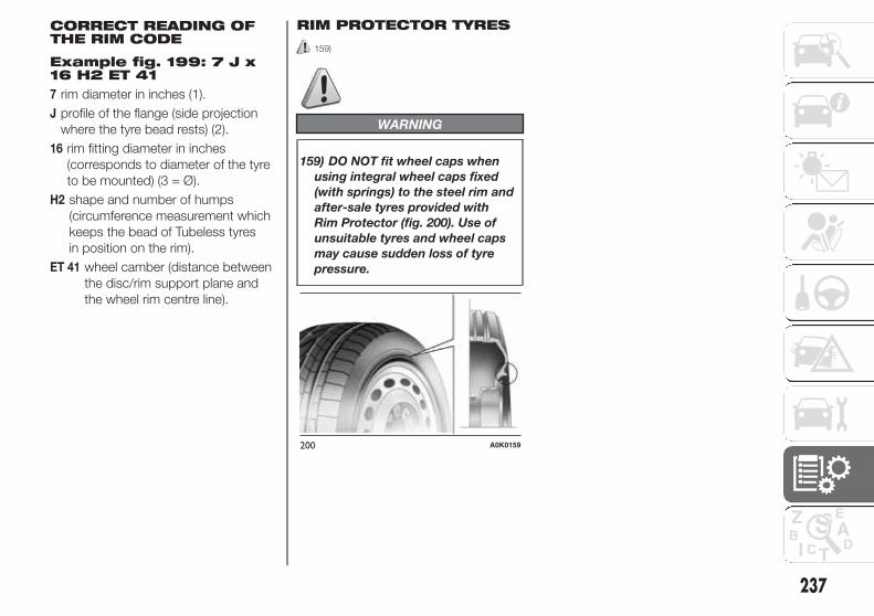
Example fig. 199: 7 J x16 H2 ET 41
7 rim diameter in inches (1).
J profile of the flange (side projection
where the tyre bead rests) (2).
16 rim fitting diameter in inches
(corresponds to diameter of the tyre
to be mounted) (3 = Ø).
H2 shape and number of humps
(circumference measurement which
keeps the bead of Tubeless tyres
in position on the rim).
ET 41 wheel camber (distance between
the disc/rim support plane and
the wheel rim centre line).
RIM PROTECTOR TYRES
159)
WARNING
159) DO NOT fit wheel caps when
using integral wheel caps fixed
(with springs) to the steel rim and
after-sale tyres provided with
Rim Protector (fig. 200). Use of
unsuitable tyres and wheel caps
may cause sudden loss of tyre
pressure.
200 A0K0159
237
CORRECT READING OFTHE RIM CODE

RIMS AND TYRES PROVIDED AS STANDARD
Versions Rims Tyres provided Snow tyresSpace-saver wheel
Rim Tyre
1.4 Turbo
Petrol
MultiAir
M
M
7Jx16 H2 ET 41 (*)195/55 R16 91V
REINFORCED (*)
195/55 R16 91Q
REINFORCED (*)T135/70 R16
100M
T125/80 R17
99M
4B x 16 ET 22
4B x 17 ET 257Jx16 H2 ET 41 205/55 R16 91V 205/55 R16 91Q
7 1/2 Jx17 H2 ET 41 225/45 R17 91W 225/45 R17 91Q
7 1/2 Jx18 H2 ET 41(*)
225/40 R18 92W
REINFORCED (*) (**)
225/40 R18 92Q
REINFORCED
1.4 Turbo
Petrol (***)
MultiAir (***)1.6 JTDM (***)2.0 JTDM (***)
7 1/2 Jx17 H2 ET 41 225/45 R17 91W 225/45 R17 91Q
T125/80 R17
99M
4B x 17 ET 25
7 1/2 Jx18 H2 ET 41225/40 R18 92W
REINFORCED (**)
225/40 R18 92Q
REINFORCED
1750 Turbo
Petrol (*)
7 1/2 Jx17 H2 ET 41 225/45 R17 91W 225/45 R17 91QT125/80 R17
99M
4B x 17 ET 25
7 1/2 Jx18 H2 ET 41225/40 R18 92W
REINFORCED (**)
225/40 R18 92Q
REINFORCED
(*) For versions/markets, where provided
(**) Tyres which cannot be fitted with chains
(***) Versions with oversized brake calipers
On versions with 195/55 R16", 205/55 R16" e 225/45 R17" tyres, reduced size snow chains can be used, with a maximum
projection of 9 mm beyond the tyre profile.
238
TE
CH
NIC
AL
SP
EC
IFIC
ATIO
NS
1.4 Turbo
2.0JTD
1.6JTD
1.4Turbo

COLD TYRE INFLATION PRESSURE (bar)
TYRES PROVIDED
VERSIONS MEASUREMENTMEDIUM LOAD FULL LOAD
Front Rear Front Rear
1.4 Turbo petrol
115/120 HP
1.6 JTDM
195/55 R16 91V REINFORCED
205/55 R16 91V
225/45 R17 91W
225/40 R18 92W REINFORCED
2,6
2,3
2,3
2,6
2,2
2,1
2,1
2,2
3,0
2,7
2,7
3,0
2,6
2,3
2,3
2,6
1.4 Turbo Petrol
105 HP (*)
195/55 R16 91V REINFORCED
205/55 R16 91V
225/45 R17 91W
225/40 R18 92W REINFORCED
2,6
2,3
2,3
2,5
2,2
2,1
2,1
2,3
2,9
2,5
2,6
2,9
2,5
2,1
2,2
2,5
1.4 Turbo MultiAir
2.0 JTDM
195/55 R16 91V REINFORCED
205/55 R16 91V
225/45 R17 91W
225/40 R18 92W REINFORCED
2,6
2,3
2,3
2,6
2,2
2,1
2,1
2,2
3,0
2,7
2,7
3,0
2,6
2,3
2,3
2,6
1750 Turbo Petrol(*)
225/45 R17 91W
225/40 R18 92W REINFORCED
2,3
2,6
2,1
2,2
2,7
3,0
2,3
2,6
Space-saver wheelT135/70 R16 100M
T125/80 R17 99M4.2
(*) For versions/markets, where provided
Add +0.3 bar to the prescribed pressure when the tyres are warm. Check correct pressure on a cold tyre.
With snow tyres, add +0.2 bar to the inflation pressure value prescribed for standard tyres.
When travelling at speeds over 160 km/h, inflate the tyres to the values specified for fully laden conditions.
239

DIMENSIONS
Dimensions are expressed in mm and refer to the vehicle equipped with its original tyres. Height is measured with car unladen.
BOOT VOLUME Unladen capacity (V.D.A. standards): = 350 dm3
A B C D E F G H
4351 955 2634 762 1465 1554 1798 1554
Small variations in size are possible depending on the dimensions of the rims
201 A0K0822
240
TE
CH
NIC
AL
SP
EC
IFIC
ATIO
NS

PERFORMANCE
Versions Top speed (km/h)Acceleration from 0-100
km/h (secs)
1.4 Turbo Petrol 120 HP 195 9,4
1.4 Turbo Petrol 105 HP (*) 185 10,6
1.4 Turbo MultiAir 163/170 HP (*) 218 7,8
1.4 Turbo MultiAir 163 HP TCT (*) 218 7.7
1.4 Turbo MultiAir 170 HP TCT 218 7.7
1750 Turbo Petrol 235 HP (*) 242 6.8
1.6 JTDM 105 HP 185 11,3
2.0 JTDM 136 HP (*) 205 –
2.0 JTDM 150 HP 210 8,8
2.0 JTDM 163 HP TCT (*) 215 8.2
2.0 JTDM 175 HP TCT 219 7.8
(*) For versions/markets, where provided
241

WEIGHTS
Weights 1.4 Turbo Petrol 1.4 Turbo MultiAir(*) 1.4 Turbo MultiAir(**)
Unladen weight (with all fluids, fuel tank
filled to 90% and without optional
equipment)
1280 1290 1305
Payload including the driver (***) 505 505 505
Maximum permitted loads (****)
1100 1100 1100– front axle
– rear axle 850 850 850
– total 1785 1795 1810
Towable loads (kg)
1300 1300 1300 / 0 (****)- braked trailer
– trailer without brakes 500 500 500
Maximum load on roof 50 50 60
Maximum load on tow hitch (trailer with
brakes)60 60 60
(*) Versions with manual gearbox
(**) Versions with Alfa TCT
(***) If special equipment is fitted (sun roof, tow hitch, etc.) the unladen car weight increases, thus reducing the specified payload in relation to the maximumpermitted loads.
(****) Hot-humid climate countries
242
TE
CH
NIC
AL
SP
EC
IFIC
ATIO
NS

Weights 1750 Turbo Petrol 235 HP (*) 1.6 JTDM
Unladen weight (with all fluids, fuel tank filled to
90% and without optional equipment)1320 1310
Payload including the driver (**) 505 505
Maximum permitted loads (***)
1100 1100– front axle
– rear axle 850 850
– total 1825 1815
Towable loads (kg)1300
1300- braked trailer
– trailer without brakes 500 500
Maximum load on roof 50 50
Maximum load on tow hitch (trailer with brakes) 60 60
(*) For versions/markets, where provided
(**) If special equipment is fitted (sun roof, tow hitch, etc.) the unladen car weight increases, thus reducing the specified payload in relation to the maximumpermitted loads.
(***) Loads not to be exceeded. The user is responsible for arranging goods in the luggage compartment and/or load platform within the maximum permitted loads.
243

Weights 2.0 JTDM (*) 2.0 JTDM (**)
Unladen weight (with all fluids, fuel tank filled to
90% and without optional equipment)1320 1335
Payload including the driver (***) 505 505
Maximum permitted loads (****)
1100 1100– front axle
– rear axle 850 850
– total 1825 1840
Towable loads (kg)1300
1300 / 600 (*****)- braked trailer
– trailer without brakes 500 500
Maximum load on roof 50 50
Maximum load on tow hitch (trailer with brakes) 60 60
(*) Versions with manual gearbox
(**) Versions with Alfa TCT
(***) If special equipment is fitted (sun roof, tow hitch, etc.) the unladen car weight increases, thus reducing the specified payload in relation to the maximumpermitted loads.
(****) Loads not to be exceeded. The user is responsible for arranging goods in the luggage compartment and/or load platform within the maximum permittedloads.
(*****) 2.0 JTDM 163 HP TCT versions
244
TE
CH
NIC
AL
SP
EC
IFIC
ATIO
NS

REFUELLING
1.4 Turbo Petrol 1.4 Turbo MultiAirRecommended fuelsand original lubricants
litres kg litres kg
Fuel tank 60 – 60 – Unleaded petrol not less
than 95 RON (EN 228
specification)including a reserve of 8 - 10 – 8 - 10 –
Engine cooling system (with
climate control)5,7 5,0 5,7 5,0
50-50 mixture of
demineralised water and
PARAFLU UP (*)
Engine sump 2,75 2,3 3,1 2,6 SELENIA StAR P.E.
Engine sump and filter 3,1 2,6 3,5 2,9
Differential/gearbox casing 2.0 1.7 2.0 1,7TUTELA TRANSMISSION
GEARFORCE
Hydraulic brake circuit with
ABS antilock brakes0,83 0,78 0,83 0,78 TUTELA TOP 4
Windscreen/rear window/
headlight washer fluid
reservoir (**)
2,8 (4,6) 2,5 (4,1) 2,8 (4,6) 2,5 (4,1)
Mixture of water and
TUTELA PROFESSIONAL
SC 35
(*) For particularly harsh climate conditions, a mixture of 60% UP and 40% demineralised water is recommended.
(**) Values in brackets refer to versions with headlight washers
245
SELENIA DIGITEK P.E.
(1.4 Turbo Petrol version)
(1.4 Turbo l version)Mu ti Air

1750 Turbo Petrol 235 HP (*) Prescribed fuels and originallubricants
litres kg
Fuel tank 60 – Unleaded petrol not less than 95
RON (EN 228 specification)including a reserve of 8 - 10 –
Engine cooling system (with climate
control)6,4 5,7
Mixture of 50% demineralised water
and 50% PARAFLUUP (***)
Engine sump 5,0 4,25SELENIA SPORT POWER
Engine sump and filter 5,1 4,35
Automatic transmission casing 2,0 1,7TUTELA TRANSMISSION
GEARFORCE
Hydraulic brake circuit with ABS (Anti-
lock braking system)0,83 0,78 TUTELA TOP 4
Windscreen/rear window/headlight
washer fluid reservoir (**)2,8 (4,6) 2,5 (4,1)
Mixture of water and TUTELA
PROFESSIONAL SC 35
(*) For versions/markets, where provided
(***) For particularly harsh climate conditions, a mixture of 60% UP and 40% demineralised water is recommended.
(**) Values in brackets refer to versions with headlight washers
246
TE
CH
NIC
AL
SP
EC
IFIC
ATIO
NS

1.6 JTDM 2.0 JTDM Recommended fuelsand original lubricants
litres kg litres kg
Fuel tank 60 – 60 – Diesel for automotive
engines (EN 590
Specification)including a reserve of 8 - 10 – 8 - 10 –
Engine cooling system (with
climate control)6,8 6,0 6,7 5,9
50-50 mixture of
demineralised water and
PARAFLU UP (**)
Engine sump 4,0 3,4 4,0 3,4
SELENIA WR FORWARD
Engine sump (versions with
Alfa TCT)– – 4.4 3.6
Engine sump and filter 4,2 3,5 4,2 3,5
Engine sump and filter
(versions with Alfa TCT)– – 4.8 4.0
Differential/gearbox casing 2.0 1.7 2.0 1.7TUTELA TRANSMISSION
GEARFORCE
Hydraulic brake circuit with
ABS antilock brakes0,83 0,78 0,83 0,78 TUTELA TOP 4
Windscreen/rear window/
headlight washer fluid
reservoir (*)
2,8 (4,6) 2,5 (4,1) 2,8 (4,6) 2,5 (4,1)
Mixture of water and
TUTELA PROFESSIONAL
SC 35
(**) For particularly harsh climate conditions, a mixture of 60% UP and 40% demineralised water is recommended.
(*) Values in brackets refer to versions with headlight washers
247

FLUIDS AND LUBRICANTS
Your car is equipped with an engine oil that has been thoroughly developed and tested in order to meet the requirements of theScheduled Servicing Plan. Constant use of the prescribed lubricants guarantees the fuel consumption and emissionspecifications. Lubricant quality is crucial for engine operation and duration.
PRODUCT SPECIFICATIONS
248
TE
CH
NIC
AL
SP
EC
IFIC
ATIO
NS
UseFluid and lubricant features for a correct use
of the carGenuine fluids and
lubricantsReplacement interval
Lubricant for
petrol engines
(1.4 Turbo Petrol
versions)
41)
SAE 5W-40 ACEA C3 grade totally synthetic
lubricant
FIAT 9.55535-S2 ification
SELENIA StAR P.E.
Contractual Technical
Reference No. F603.D08
According to the
Scheduled Servicing
Plan
Lubricant for
petrol engines
versions)
SAE 0W-30 ACEA C2grade totally synthetic
lubricant
FIAT 9.55535-S2 specification
SELENIA P.E.
Contractual Technical
Reference No. F020.B12
According to the
Scheduled Servicing
Plan
DIGITEK (1.4 Turbo MultiAir
41)
spec

UseFluid and lubricant features for a correct use
of the carGenuine fluids and
lubricantsReplacement interval
Lubricant for
petrol engines (for
1750 Turbo petrol
versions only)
41)
SAE 5W-40 ACEA C3 grade totally synthetic
lubricant
FIAT 9.55535-GH2 specification
SELENIA SPORT
POWER
Contractual Technical
Reference No. F052.H12
According to
Scheduled Servicing
Plan
Lubricant for
diesel engines
41)
SAE 0W-30 ACEA C2 grade totally synthetic
lubricant
FIAT 9.55535-DS1 specification
SELENIA WR
FORWARD
Contractual Technical
Reference No. F842.F13
According to
Scheduled Servicing
Plan
In case of emergency, if lubricants with the prescribed specifications are not available, products with the minimum indicated
ACEA performance can be used for topping up; in this case optimal performance of the engine is not guaranteed.
For MultiAir system engines only use lubricants with indicated SAE grade and specifications.
IMPORTANT
41) The use of products with different specifications than those indicated above could cause damage to the engine that
is not covered by the warranty.
249

UseFluid and lubricant features for a correct use
of the carGenuine fluids and
lubricantsApplications
Lubricants and
greases for drive
transmission
SAE 75W grade synthetic lubricant.
FIAT 9.55550-MZ6 classification
TUTELA
TRANSMISSION
GEARFORCE
Contractual Technical
Reference No. F002.F10
Gearboxes and
differentials
(mechanical)
Molybdenum disulphide grease, for use at high
temperatures. NL.G.I. 1-2 consistency
FIAT 9.55580 classification
TUTELA ALL STAR
Contractual Technical
Reference No. F702.G07
Wheel side constant
velocity joints
Grease for constant velocity joints with low friction
coefficient. NL.G.I. 0-1 consistency
FIAT 9.55580 classification
TUTELA STAR 700
Contractual Technical
Reference No. F701.C07
Differential-side
constant velocity joints
Lubricant for
electro-hydraulic
actuator (versions
with Alfa TCT)
Fully synthetic oil with dedicated additive
FIAT 9.55550-SA1 classification
TUTELA CS SPEED
Contractual Technical
Reference No. F005.F98
Lubricant for electro-
hydraulic actuator
Brake fluid
Synthetic fluid for brake and clutch systems.
Exceeds specifications: FMVSS no. 116 DOT 4,
ISO 4925, SAE J1704.
FIAT 9.55597 classification
TUTELA TOP 4
Contractual Technical
Reference No. F001.A93
Hydraulic brakes and
hydraulic clutch
controls
250
TE
CH
NIC
AL
SP
EC
IFIC
ATIO
NS

UseFluid and lubricant features for a correct use
of the carGenuine fluids and
lubricantsApplications
Protective agent
for radiators
Red protective agent with antifreeze action, based
on inhibited monoethylene glycol with organic
formula. Exceeds the CUNA NC 956-16, ASTM D
3306 specifications.
FIAT 9.55523 classification
PARAFLUUP (*)
Contractual Technical
Reference No. F101.M01
Usage percentage:
50% demineralised
water 50%
PARAFLUUP (**)
Diesel fuel
additive
Antifreeze additive for diesel, with protective action
for diesel engines.
TUTELA DIESEL ART
Contractual Technical
Reference No. F601.L06
To be mixed with diesel
(25 cc per 10 litres)
Windscreen/rear
window/headlight
washer fluid
Mixture of alcohol, water and surfactants CUNA
NC 956-11
FIAT 9.55522 classification
TUTELA
PROFESSIONAL SC 35
Contractual Technical
Reference No. F201.D02
To be used diluted or
undiluted in screen
washer/wiper systems
(*)IMPORTANT Do not top up or mix with other fluids which have different specifications from those described.
(**)When the vehicle is used in particularly harsh weather conditions, we recommend using a mixture of 60% PARAFLUUP and 40% demineralised water.
251

FUEL CONSUMPTION
The fuel consumption figures given in the tables below are determined on the basis of the type-approval tests laid down by
specific European Directives.
The procedures below are followed for measuring consumption:
❒ urban cycle: cold starting followed by driving that simulates urban use of the car;
❒ extra-urban cycle: frequent accelerating in all gears, simulating extra-urban use of the car: speed varies between 0 and 120
km/h;
❒ combined fuel consumption: calculated with a weighting of approximately 37% of the urban cycle and 63% of the extra-
urban cycle.
IMPORTANT The type of route, traffic conditions, weather conditions, driving style, general condition of the car, trim level/
equipment/accessories, use of the climate control, car load, presence of roof racks and other situations that adversely affect
the aerodynamics or wind resistance lead to different fuel consumption figures than those measured.
252
TE
CH
NIC
AL
SP
EC
IFIC
ATIO
NS

2.0 JTDM 175 HP TCT 5.2 3.9 4.4
253
(*) For versions/markets, where provided
FUEL CONSUMPTION ACCORDING TO THE CURRENT EUROPEAN DIRECTIVE (litres/100 km)
Versions Urban Extra-urban Combined
1.4 Turbo Petrol 8,3 5,3 6,4
1.4 Turbo MultiAir 7,6 4,6 5,7
1.4 Turbo MultiAir 163/170 HP TCT 6.6 4.3 5.1
1.4 Turbo MultiAir 170 HP TCT (*) 6.4 4.2 5.0
1750 Turbo Petrol 235 HP (*) 10.8 5.8 7.6
1.6 JTDM 105 HP 5,0 3,4 4,0
2.0 JTDM 136/150 HP 5.0 3.7 4.2
2.0 JTDM 163 HP TCT (*) 5.2 3.9 4.4

CO2 EMISSIONS
The CO2 emission levels given in the following tables refer to combined consumption.
Versions CO2 emissions according to the current European directive (g/km)
1.4 Turbo Petrol 148
1.4 Turbo MultiAir 163/170 HP 131
1.4 Turbo MultiAir 170 HP TCT 119
1.4 Turbo MultiAir 163 HP TCT (*) 119
1.4 Turbo MultiAir 170 HP TCT (*) 117
1750 Turbo Petrol 235 HP (*) 177
1.6 JTDM 105 HP 104
2.0 JTDM 136/150 HP 110
2.0 JTDM 175 HP TCT 116
2.0 JTDM 163 HP TCT (*) 116
(*) For versions/markets, where provided
254
TE
CH
NIC
AL
SP
EC
IFIC
ATIO
NS

PRESCRIPTIONS FOR HANDLING THE VEHICLE AT THE END OFITS LIFE
255
FCA has been committed for many years to safeguarding the environment through the constant improvement of its production
processes and manufacturing products that are increasingly "eco-compatible". To grant customers the best possible service
in terms of respecting environmental laws and in response to European Directive 2000/53/EC governing vehicles at the end of
their life, FCA is offering its customers the chance to hand over their vehicle at the end of its life without incurring any additional
costs. The European Directive sets out that when the vehicle is handed over, the last keeper or owner should not incur any
expenses as a result of it having a zero or negative market value.
To hand your vehicle over at the end of its life without extra cost, contact one of our dealerships if you are purchasing another
vehicle or an FCA-authorised collection and scrapping centre. These centres have been carefully chosen to offer high quality
service for the collection, treatment and recycling of vehicles at their end of life, respecting the surrounding environment.
You can find further information on these collection and scrapping centres either from an FCA dealership or by calling the
number in the Warranty Booklet or by consulting the websites of the various FCA brands.

WHAT TO DO IF
Fault Possible solution
... A TYRE IS PUNCTURED. Use the Fix&Go Automatic tyre repair kit. See page 170.
... A TYRE DEFLATES. Restore the correct pressure. See page 236.
... THE BATTERY IS FLAT. –See page 211 or contact an
Alfa Romeo Dealership.
... THE INTERNAL ROOF LIGHTS DO NOT
COME ON.Replace the bulb.
See page 180 or contact an
Alfa Romeo Dealership.
... AN EXTERNAL BULB (main beam, dipped
beam headlights...) DOES NOT COME ON.
Check the relevant protection fuse.See page 181 or contact an
Alfa Romeo Dealership.
Replace the bulb.See page 177 or contact an
Alfa Romeo Dealership.
... THE REMOTE CONTROL DOES NOT
WORK.
Replace the batteries inside the remote
control.See page 12.
... THE KEY WITH REMOTE CONTROL HAS
BEEN LOST.Request an additional remote control. See page 12
... AN ELECTRIC WINDOW DOES NOT
WORK
Check the relevant protection fuse.See page 181 or contact an
Alfa Romeo Dealership.
Have the relevant window raising / lowering
motor checked
Contact an Alfa Romeo
Dealership.
... AN INSTRUMENT PANEL WARNING
LIGHT SWITCHES ON.– See page 99.
... THE ENGINE DOES NOT START, THE
STARTER DOES NOT TURNThe battery is flat; it needs replacing. See page 211.

Fault Possible solution
... THE ENGINE DOES NOT START OR
STOPS WHEN DRIVING.Check that there is sufficient fuel in the tank. See page 245.
... THE ENGINE DOES NOT START
FOLLOWING AN IMPACT.
Check whether the fuel cut-off system has
intervened.See page 45.
... ENGINE COOLANT TEMPERATURE TOO
HIGH INDICATION.Check the engine coolant level.
See page 209, contact an
Alfa Romeo Dealership.
... EXCESSIVE BRAKE PAD WEAR
INDICATION.Replace the worn brake pads.
Contact an Alfa Romeo
Dealership.
... IT IS NOT POSSIBLE TO ENGAGE THE
GEARS.Have the gearbox/transmission checked.
Contact a dedicated Alfa
Romeo Dealership.
... LOSS OF ENGINE PERFORMANCE,
POOR DRIVEABILITY, HIGH EXHAUST
EMISSIONS AND CONSUMPTION.
Have the EOBD/injection system checked.See page 74, contact an Alfa
Romeo Dealership.
... THE ABS DOES NOT WORK. Have the ABS checked.See page 63, contact an Alfa
Romeo Dealership.

This page is intentionally left blank

DASHBOARD
The presence and position of controls, instruments and gauges may vary according to different versions.
1. Adjustable air vent 2. Passenger front air bag 3. Control buttons 4. Windscreen wiper/rearscreen wiper/trip computer control lever 5. Instrumentpanel 6. Exterior lighting control lever 7. Driver front air bag 8. Cruise Control (for versions/markets, where provided) 9. Uconnect Radio/UconnectRadio Nav (for versions/markets, where provided) 10. Heating/ventilation/climate control system controls 11. Glove compartment
1 A0K0730
259
RIG
HT
HA
ND
DR
IVE
VE
RS
ION
S

CONTROL PANEL AND INSTRUMENTS
VERSIONS WITH MULTIFUNCTIONAL DISPLAY
A. Speedometer (speed indicator) B. Multifunctional display C. Rev counter D. Fuel level gauge with reserve warning lightE. Engine coolant temperature gauge and excessive temperature warning light
warning lights supplied in diesel versions only. On diesel versions the rpm gauge end of scale is set at 6000 rpm.
WARNING Instrument background colour and type may vary according to the version.
2 A0K2302
260
RIG
HT
HA
ND
DR
IVE
VE
RS
ION
S

VERSIONS WITH RECONFIGURABLE MULTIFUNCTIONAL DISPLAY
A. Speedometer (speed indicator) – B. Reconfigurable multifunctional display – C. Rev counter – D. Fuel level gauge with reserve warning light – E.Engine coolant temperature gauge and excessive temperature warning light
warning lights supplied in diesel versions only. On diesel versions the rpm gauge end of scale is set at 6000 rpm.
WARNING Instrument background colour and type may vary according to the version.
3 A0K2303
261
RIG
HT
HA
ND
DR
IVE
VE
RS
ION
S

CHANGING A FUSE
FUSEBOX ONDASHBOARD
Insert a hand in the seat A fig. 4 and
lower the flap B to access the fuses.
The fuses are located in the fusebox
shown in fig. 5.
Notto the description of “In an emergency”chapter.
4 A0K0731
5 A0K0249
2
RIG
HT
HA
ND
DR
IVE
VE
RS
ION
Se For fuse protected devices refer
62


NOTES


INDEX
ABS.............................................. 62
Additional heater ............................ 35
AFS adaptive lights (AdaptiveFrontlight System) ........................ 38
Air cleaner...................................... 210
Alarm ............................................. 14
“Alfa DNA” system ........................ 66
– Driving modes ........................... 66
– "Natural" Mode.......................... 67
Alfa Romeo Code system ............. 10
ALFA TCT ...................................... 151
Ashtray .......................................... 48
ASR system (Anti-SlipRegulation)................................... 63
Automatic dual zone climatecontrol ......................................... 28
Battery.......................................... 211
– advice for extending lifetime ...... 211
– replacement .............................. 211
Battery (recharging) ........................ 191
Bodywork
– maintenance ............................. 216
– protection againstatmospheric agents................... 216
– warranty .................................... 216
Bonnet........................................... 59
– Closing...................................... 59
– Opening .................................... 59
Brakes ........................................... 233
– brake fluid level.......................... 209
bulb replacement ........................... 178
Bulb replacement
– exterior lights............................. 177
– interior lights.............................. 180
Bulbs
– types of bulbs ........................... 175
Carrying children safely ................. 133
CBC (Cornering Brake Control)system......................................... 63
Central locking ............................... 45
Changing a bulb............................. 173
– General instructions................... 173
Changing a wheel .......................... 165
Checking levels .............................. 205
Cigar lighter.................................... 48
Cleaning and maintenance
– bodywork.................................. 216
– car interior ................................. 218
– front headlights ......................... 217
– leather parts .............................. 218
– leather seats.............................. 218
– plastic and coated parts............ 218
– seats and fabric parts................ 218
Climate control............................... 22
– Central air diffusers.................... 22
– Rear air diffuser ......................... 22
– Side air diffusers........................ 22
– Upper air diffusers ..................... 22
Climatic comfort............................. 23
– Diffusers .................................... 23
Clutch ............................................ 232
CO2 emissions............................... 254
CODE Card.................................... 11
Control buttons .............................. 85
Control panel and instruments ....... 94
– Multifunction display.................. 94
– Reconfigurable multifunctiondisplay....................................... 95
Controls ......................................... 44
Courtesy light
– bulb replacement ...................... 181
Cruise Control ................................ 40
Daytime running lights (DRL) ......... 35
Diesel filter ..................................... 210
Dimensions .................................... 240
Dipped beam headlights
– bulb replacement ...................... 177
Direction indicators................... 37-178
– bulb replacement ...................... 178
– “Lane change” function ............. 37
Display ........................................... 84
Doors............................................. 51
– Child safety device .................... 52
– Door centrallocking/unlocking ...................... 51
DPF (particulate filter) ..................... 81

DST system (Dynamic SteeringTorque)......................................... 64
Dual Pinion active steering ............. 74
Dusk sensor................................... 36
EBD system.................................. 62
Electric sun roof ............................. 49
Electric windows ............................ 53
– Controls .................................... 53
"Electronic Q2" system ("E-Q2") .... 64
Engine codes - bodyworkversions ....................................... 223
Engine compartment
– washing .................................... 217
Engine coolant temperatureindicator....................................... 96
Engine............................................ 226
– engine cooling system fluidlevel........................................... 209
– marking..................................... 222
Engine oil
– consumption ............................. 208
– level check ................................ 208
EOBD system ................................ 74
ESC (Electronic Stability Control)system......................................... 62
External courtesy lights .................. 38
External lights................................. 35
Extinguisher ................................... 49
Filling the tank............................... 80
Fitting "Universal" child seat ........... 134
Fix&Go Automatic kit...................... 170
Flashing ......................................... 37
Fluids and lubricants ...................... 248
Fog lights ................................. 44-178
"Follow Me Home" device ............. 37
Front airbags................................. 140
Front armrest ................................. 46
Front driver side airbag................... 140
Front passenger airbag .................. 140
Front roof light
– bulb replacement ...................... 180
Fuel consumption .......................... 252
Fuel cut-off system......................... 45
Fuel level gauge ............................. 96
Fuel supply..................................... 231
Fuel tank cap ................................. 80
Fuses (if a fuse blows) .................... 181
Gear Shift Indicator ....................... 85
Glove compartment courtesylight
– bulb replacement ...................... 181
Handbrake.................................... 149
Hazard warning lights..................... 44
HBA system................................... 64
Headlights...................................... 61
– Adjusting headlights abroad ...... 61
– bulb replacement ...................... 177
– Headlight alignment corrector.... 61
– Light beam direction.................. 61
Headlight washers ......................... 215
Head restraints............................... 18
– "Anti-Whiplash" device .............. 19
– Front headrests ......................... 18
– Rear head restraints .................. 19
Hill Holder system .......................... 63
Identification data
– bodywork paint plate................. 222
– Chassis marking........................ 222
– engine marking.......................... 222
– identification data plate.............. 222
Ignition device ................................ 15
– Steering lock ............................. 16
Installing a Universal Isofix childseat.............................................. 137
Installing electrical/electronicdevices ........................................ 76
Interior fittings ................................ 46
Interiors (cleaning) .......................... 218
iTPMS system................................ 72
Jack.............................................. 165
Light clusters
– front light clusters (changing abulb).......................................... 177
– rear light clusters (changing abulb).......................................... 178
Luggage compartment courtesylight
– bulb replacement ...................... 180
IND
EX

Luggage compartment................... 56
– Bag hooks................................. 58
– Closing the luggagecompartment ............................ 56
– Emergency luggagecompartment opening............... 56
– Extending the luggagecompartment ............................ 57
– Luggage compartmentinitialisation................................ 56
– Luggage retaining net................ 58
– Opening the luggagecompartment ............................ 56
– Securing your load .................... 58
Main beam headlights .................. 37
– bulb replacement ...................... 177
Maintenance and care
– heavy-duty use of the car .......... 204
– periodic checks......................... 204
Manual climate control ................... 24
Menu options................................. 87
Money holder ................................. 48
MSR system .................................. 64
Multifunction display....................... 84
Number plate lights
– bulb replacement ...................... 179
Parking ......................................... 149
– Handbrake ................................ 149
Parking lights ................................. 36
Parking sensors ............................. 77
Performance .................................. 241
Pollen filter ..................................... 210
Power sockets ............................... 47
Pre-Fill system (RAB - ReadyAlert Brake) .................................. 64
Preparation for "Isofix" child seat .... 137
Pretensioners ................................. 131
– Load limiters.............................. 131
Protecting the environment ............ 81
Radio transmitters and mobilephones ........................................ 76
Rain sensor.................................... 39
Raising the car ............................... 192
Rear armrest .................................. 47
Rear fog lights................................ 44
Rear fog lights/reversing lights........ 178
Rear roof light
– bulb replacement ...................... 180
Rear view mirrors ........................... 20
– Door mirrors .............................. 21
– Internal mirror ............................ 20
Rear window washer jets ............... 215
Rear window washer
– rear window washer fluid level ... 209
Rear window washer/wiper ............ 40
Rear window wiper
– blade replacement..................... 214
Reconfigurable multifunctiondisplay ......................................... 84
Refuelling ....................................... 245
Refuelling the car ........................... 80
Rev counter ................................... 96
Rim Protector (tyres)....................... 237
Roof lights...................................... 42
– Courtesy lights .......................... 43
– Front roof light ........................... 42
– Glove compartment light ........... 43
– Luggage compartment rooflight ........................................... 43
– Rear roof light............................ 43
Roof rack/ski rack .......................... 60
Safe Lock (device)......................... 13
Saving fuel ..................................... 158
SBR system (Seat BeltReminder) .................................... 129
Scheduled servicing ....................... 196
Scheduled Servicing Plan............... 197
Seat belts....................................... 128
– Use ........................................... 128
Seats ............................................. 16
– Front seats ................................ 16
Setup menu ................................... 86
Side airbags (Side Bags -Window Bags).............................. 144
Side bags (front side airbags) ......... 144
Side lights/brake lights ................... 178
Side lights/daytime running lights(DRL)
– bulb replacement ...................... 177
Side lights/dipped beamheadlights .................................... 36

Ski compartment ........................... 47
“Smart Bag” system (Multistagefront airbags)................................ 140
Snow chains ................................. 161
Snow tyres..................................... 160
Speedometer (speed indicator) ...... 96
Starting the engine......................... 148
Starting the engine......................... 164
– Bump starting ........................... 164
– Jump starting ............................ 164
Start&Stop system......................... 69
Steering lock.................................. 16
Steering system ............................. 235
Steering wheel ............................... 19
Storage compartments .................. 46
Storing the car ............................... 162
Sun visors ...................................... 48
Suspension.................................... 234
Symbols......................................... 10
Technical specifications ................ 222
The keys ........................................ 11
– CODE Card............................... 11
– Key without remote control........ 11
– Key with remote control............. 11
Third brake lights
– bulb replacement ...................... 179
Towing the car ............................... 192
– Attaching the tow hook ............. 192
Towing trailers ................................ 160
– Installing a tow hook.................. 160
Transmission .................................. 232
TRIP button.................................... 98
Trip Computer ................................ 96
Tyres
– correct tyre reading ................... 236
– Fix&Go Automatic (kit) ............... 170
– inflation pressure ....................... 239
Using the Gearbox........................ 150
Warning lights and messages....... 99
Weights.......................................... 242
Welcome movement ...................... 85
Wheel rims
– correct reading of the rimcode ......................................... 236
Wheels and tyres ........................... 212
– changing a wheel ...................... 165
– spare wheel............................... 236
– tyre inflation pressure................. 239
Wheels and tyres provided ............. 238
Wheels........................................... 236
– rims and tyres ........................... 236
Window bags (side airbags forhead protection) ........................... 144
Window cleaning............................ 38
Windows (cleaning) ........................ 217
Windscreen/rear window wiper
– blades ....................................... 213
Windscreen washer
– windscreen washer fluid level .... 209
Windscreen washer nozzles ........... 214
Windscreen washer/wiper .............. 38
– “Smart washing” function .......... 39
Windscreen wiper
– replacing wiper blades............... 213
Wiring for radio system .................. 75
IND
EX


TECHNICAL SERVICES – SERVICE ENGINEERING
Publication no. 60438 – Edition –All rights reserved. Reproduction, even in part is prohibited without written permissionfrom S.p.A.
S E R V I C E
357
MOPAR
FCA Italy S.p.A. - Largo Senatore G. Agnelli, 3 - 10040 Volvera - Torino (Italia) 09/2015
FCA Italy
4

We really know your car because we invented, designed and built it: we really know every single detail. At Alfa Romeo Service authorised workshops you can find technicians directly trained by us,
offering quality and professionalism for all service operations. Alfa Romeo workshops are always close to you for the regular servicing operations, season checks
and practical recommendations by our experts.With Alfa Romeo Genuine Parts you keep the reliability, comfort and performance features
of your new car unchanged in time: that's why you bought it for.Always ask for Genuine Parts for the components used on our cars; we recommend them because
they come from our steady commitment in research and development of highly innovative technologies.For all these reasons: rely on Genuine Parts, because they are the only ones
designed by Alfa Romeo for your car.
SAFETY: BRAKING SYSTEM
ENVIRONMENT: PARTICULATE FILTERS, CLIMATE CONTROL MAINTENANCE
COMFORT: SUSPENSION AND WINDSCREEN WIPERS
PERFORMANCE: SPARK PLUGS,INJECTORS AND BATTERIES
LINEACCESSORI ROOF RACK BARS, WHEEL RIMS
WHY CHOOSING GENUINE PARTS
Cop Alfa Giulietta EN QUAD 12/03/14 08.33 Pagina 2

O W N E R H A N D B O O K
Alfa Services
ENGLISH
Cop Alfa Giulietta EN QUAD 12/03/14 08.33 Pagina 1