Embed Size (px)
Citation preview

IEEE Communications Magazine • February 2011102 0163-6804/11/$25.00 © 2011 IEEE
1 A full list of results fromall partners is available athttp://www.easy-c.com.
2 See ict-artist4g.eu.
INTRODUCTION
High spectral efficiency (i.e., high aggregatedcell data rate per unit of spectrum) is especial-ly important for data networks. Mobile datatraffic has recently surged due to the availabili-ty of affordable data dongles, notebooks, tabletcomputers with third-generation (3G) radiomodules, and smartphones with web-orienteduser interfaces. Vodafone, for example, hasobserved 70 percent growth of data trafficwithin one year for their European mobile net-works. So far, 3G networks could support thetraffic growth. However, eventually, more effi-cient wireless technology and novel deploy-ment concepts l ike small cells andheterogeneous networks are needed to providethe required capacity.
Ubiquitous user experience is key for the enduser to have a guaranteed minimum service
quality corresponding to a minimum data rate.Denser network deployments address this issuecaused by low link budget at the cell edge. How-ever, this goes along with larger areas where thetransmission is limited by interference.
Long Term Evolution (LTE) and mobileWiMAX use multiple-input multiple-output(MIMO)-orthogonal frequency-division multi-plexing (OFDM) and achieve improved spectralefficiency within one cell. However, inter-cellinterference is still preventing these technolo-gies from coming close to the theoretical ratesfor multi-cell networks. There are two funda-mental ways to deal with inter-cell interference:Coordination of base stations to avoid interfer-ence and constructive exploitation of interfer-ence through coherent base station cooperation.Conceptually, we extend single-cell MIMO tech-niques, such as multi-user (MU-MIMO), tomultiple cells.
This article shows results from the EASY-C1
project, which focused on coordinated multi-point (COMP) from 2007 to 2010 and set up twomultisite testbeds for LTE-based COMP inDresden and Berlin. ARTIST4G2 and otherforthcoming projects will continue to use theseplatforms.
COMP is a main element on the LTEroadmap beyond Release 9. In LTE Release 11,some simpler COMP concepts may appear, butit is generally expected that advanced COMPconcepts will take longer to be mature enoughfor commercial use.
The main scope of this article is to outlinethe basic COMP concepts, and highlight thepotentials and technical challenges when intro-ducing them in future mobile networks. More-over, we sketch practical COMP schemes foruplink and downlink, assess their performance inlarge-scale network simulations, and use field tri-als in urban areas to demonstrate the maturityof COMP.
ABSTRACT
Coordinated multipoint or cooperativeMIMO is one of the promising concepts toimprove cell edge user data rate and spectralefficiency beyond what is possible with MIMO-OFDM in the first versions of LTE or WiMAX.Interference can be exploited or mitigated bycooperation between sectors or different sites.Significant gains can be shown for both theuplink and downlink. A range of technicalchallenges were identified and partiallyaddressed, such as backhaul traffic, synchro-nization and feedback design. This article alsoshows the principal feasibility of COMP in twofield testbeds with multiple sites and differentbackhaul solutions between the sites. Theseactivities have been carried out by a powerfulconsortium consisting of universities, chip man-ufacturers, equipment vendors, and networkoperators.
IMT-ADVANCED AND NEXT-GENERATIONMOBILE NETWORKS
Ralf Irmer, Vodafone
Heinz Droste, Deutsche Telekom
Patrick Marsch, Michael Grieger, and Gerhard Fettweis, Technische Universität Dresden
Stefan Brueck, Qualcomm CDMA Technologies GmbH
Hans-Peter Mayer, Alcatel-Lucent Bell Labs
Lars Thiele and Volker Jungnickel, Fraunhofer Heinrich-Hertz-Institut
Coordinated Multipoint: Concepts,Performance, and Field Trial Results
IRMER LAYOUT 1/19/11 3:33 PM Page 102
IEEE Communications Magazine • February 2011 103
COORDINATION AND COOPERATIONIN MOBILE NETWORKS
One key element of mobile radio networks isspatial reuse (i.e., the reuse of resource elementssuch as timeslots or frequency bands) in a geo-graphical distance, where the signal strength isreduced due to path loss, shadowing, and so on.Historically, this was achieved using networkplanning with certain frequency reuse patterns,which have, however, the drawback of poorresource utilization. 3G and 4G technologies areusing full frequency reuse, which in turn leads tointerference between the cells.
In [1, 2] network coordination has been pre-sented as an approach to mitigate intercell inter-ference and hence improve spectral efficiency.Figure 1 shows the cooperation architecture forCOMP. The same spectrum resources are usedin all sectors, leading to interference for termi-nals (user equipment [UE] in Third GenerationPartnership Project [3GPP] terminology) at theedge between the cells, where signals from mul-tiple base stations are received with similar sig-nal power in the downlink. Multiple sectors ofone base station (eNB in 3GPP LTE terminolo-gy) can cooperate in intrasite COMP, whereasintersite COMP involves multiple eNBs.
The sectors at one site can be different self-sustained units, or different remote radio headslinked via fiber to a central baseband unit. TheeNBs may be interconnected by the logical X2interface. Physically, this could be a direct fastfiber link, or a multi-hop connection involvingdifferent backhaul technologies.
The cooperation techniques aim to avoid orexploit interference in order to improve the cell-edge and average data rates. COMP can beapplied both in the uplink and downlink. Allschemes come with the cost of increaseddemand on backhaul (high capacity and lowlatency), higher complexity, increased synchro-nization requirements, more channel estimationeffort, more overhead, and so on. The aim ofthis article is to highlight the potentials ofCOMP and its technical challenges to beaddressed for introducing it in next-generationmobile networks.
EVALUATION BY SIMULATION ANDFIELD TRIALS
Different approaches to COMP can be analyzedusing system-level simulations with hexagonalcells and evaluation methodologies customary inthe 3GPP, Next Generation Mobile Networks(NGMN), and International TelecommunicationUnion (ITU). Unless otherwise specified, theintersite distance in all computer simulationshas been set to 500 m, a terminal speed of 3km/h is assumed, and the system bandwidth is10 MHz.
The results of such simulations will be pre-sented in this article. However, it is not enoughto evaluate the feasibility of an approach solelybased on simulations. Field trials are essential tofind out the critical technical issues, and theyencourage an end-to-end view. The EASY-C
project has set up two outdoor testbeds withslightly different underlying technology andfocus, as shown in Table 1; see also [3–5].
UPLINK COORDINATED MULTIPOINT
OVERVIEWTheoretical work has shown that uplink (UL)COMP offers the potential to increase through-put significantly [1, 2], in particular at the celledge, which leads to enhanced fairness overall.Modeling some practical aspects such as a rea-sonably constrained backhaul infrastructureand imperfect channel knowledge, UL COMPpromises average cell throughput gains on theorder of 80 percent, and roughly a threefoldcell edge throughput improvement [6]. Thechannel information is available in the networkwithout resource-consuming feedback transmis-sions in the uplink. Also, the terminals need nomodifications in order to support UL COMP.Therefore, base station cooperation may beeasier to implement than in the downlink (DL).Only the interface between base station sites(X2) needs to be defined. In case of jointdetection in the UL, higher X2 capacity isneeded than for joint transmission in the DL.Although the UL capacity is not the bottleneckin today’s networks, guaranteeing a minimumdata rate, especially for cell edge users, isimproving user experience, and UL COMPmay be used to carry control traffic necessaryto implement DL COMP.
In general, the UL COMP schemes can beclassified as:
Interference-aware detection: Here, no coop-eration between base stations is necessary;instead, base stations also estimate the links tointerfering terminals and take spatially coloredinterference into account when calculatingreceive filters (interference rejection combining).
Joint multicell scheduling, interference pre-
Figure 1. Base station cooperation: intersite and intrasite COMP.
X2 interface (eNB-eNB)
Cell / sector Mobile
terminal (UE)
eNB
eNB eNB
eNB
Inter-Site COMP
Cell edge
Intra-Site COMP
IRMER LAYOUT 1/19/11 3:33 PM Page 103

IEEE Communications Magazine • February 2011104
diction, or multicell link adaptation, requiringthe exchange of channel information and/orscheduling decisions over the X2 interfacebetween base stations [7].
Joint multicell signal processing. Here,degrees of freedom exist in the way that decod-ing of terminals may take place in a decentral-ized or centralized way, and to which extentreceived signals are preprocessed before infor-mation exchange among base stations. In gener-al, there is a trade-off between using backhaulefficiently by a maximum extent of preprocessing(e.g., as in distributed interference subtraction,DIS, where decoded data is exchanged), butobtaining less CoMP gain, or using a large back-haul capacity (as in the case of the distributedantenna system, DAS, where quantized receivesignals are exchanged) and obtaining a betterperformance.
SELECTED SIMULATION RESULTSIn the following section selected UL cooperationschemes are introduced. During performanceevaluation it is distinguished between gains ofintrasite and intersite cooperation, where inter-site cooperation needs X2 backhaul capacity.
Uplink Interference Prediction — The basicidea of UL interference prediction [7] is to per-form link adaptation based on predicted signal-to-interference-plus-noise ratio (SINR) valuesthat are likely to occur during the associateddata transmissions. Prediction is enabled byexchange of resource allocation informationwithin a cluster of cooperating cells. In addition,the UL receivers provide channel state informa-tion related not only to their associated termi-nals, but also to the strongest terminals ofneighboring cells. Due to interference predic-tion, more appropriate link adaptation can berealized, and hence the performance can beimproved. The exchange of resource allocationinformation between two cells causes only mod-erate backhaul traffic in the range of 8 Mb/s.Whereas performance gains with intrasite coop-
eration prove to be rather low, we observe up to25 percent gain in spectral efficiency and 29 per-cent gain with respect to baseline cell edgethroughput if intersite cooperation including upto six interfering cells is simulated. The predic-tion accuracy degrades if the channel state infor-mation gets outdated. Therefore, the X2 latencyshould not exceed 1 ms, even at low terminalspeed.
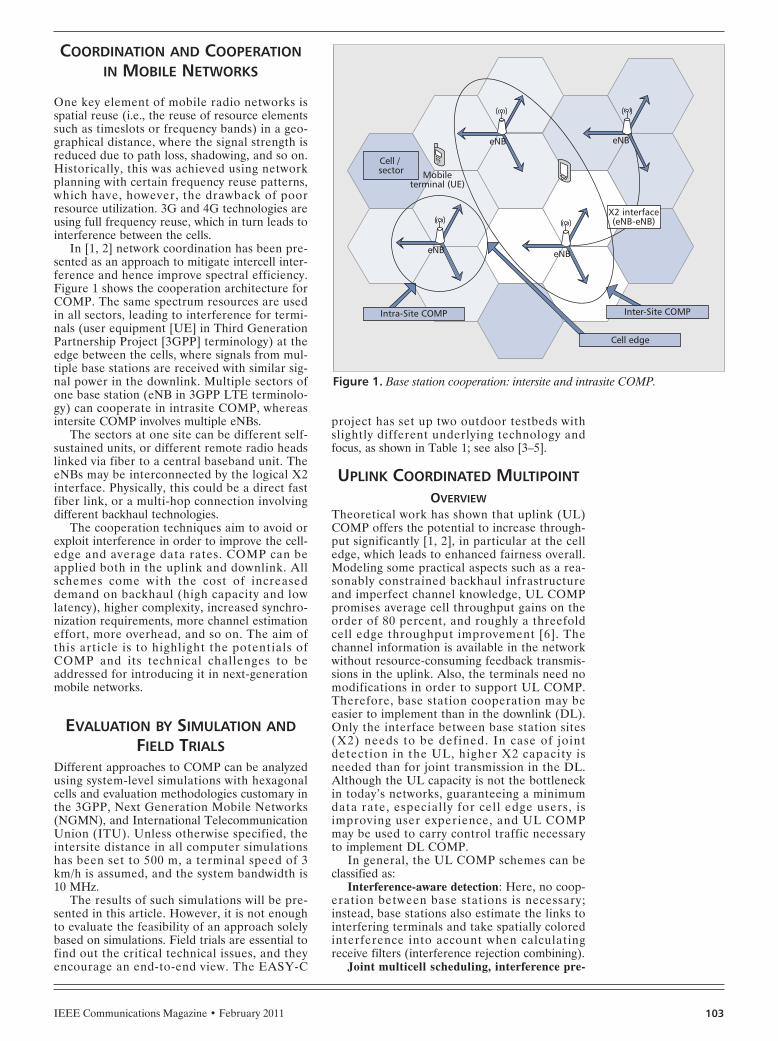
Uplink Joint Detection — Uplink joint detec-tion means that signals received at different sec-tors are jointly processed [8]. Hence, virtualMIMO antenna arrays may spread out over dif-ferent users as well as different base station sec-tors at the network side. Most of theinformation exchange between cooperating cellsis caused by sharing the quantized basebandsamples received in each cell. Channel stateinformation and resource allocation tables areshared in the cooperation cluster as well. Firstestimates reveal that even with consideration ofless than half the cooperation cluster size asdescribed above for interference prediction, thecell-to-cell X2 traffic would exceed 300 Mb/s for10 MHz system bandwidth. This high amount ofbackhaul traffic motivates the investigation ofintrasite joint detection. In case of intersite jointdetection including up to three sectors per ter-minal, gains in spectral efficiency and cell edgethroughput account for 35 and 52 percent,respectively (2). Sticking with intra-site jointdetection, the improvements drop only moder-ately to 25 percent on average and 24 percent atthe cell edge (3).
Combining high throughput and low latencyas required by joint detection will cause a costburden for the backhaul, specifically the X2interface. Therefore, a combination of intrasitejoint detection (no X2 needed) and intersiteinterference predictions (low throughputdemand) has been considered. This even outper-forms the throughput-demanding intersite jointdetection, as shown in Fig. 2. However, the bur-den of low-latency X2 remains.
Table 1. COMP testbeds developed within the EASY-C project.
Dresden testbed Berlin testbed
Environment Dense urban
Trial setup 10 sites with up to a total of 28 sectors 4 sites with up to 10 sectors
Frequency 2.68 GHz DL, 2.53 GHz UL
Baseline technologyOFDMA in DL and UL, scalable bandwidth 5–20MHz, transmissions limited to a maximum of 40resource blocks (PRBs) in UL and 10 PRBs in DL.
DL: 2 × 2 MIMO-OFDMA, UL: 1 × 2 SC-FDMA,scalable bandwidth 1.5–20 MHz, full bandwidthcan be used in both up- and downlink
ProcessingReal-time DL transmission. For uplink COMPoffline processing. Scheduling is investigated inquasi-realtime.
Real-time PHY, adaptive MIMO multiple access andnetwork layer. PHY is extended for DL CoMP.
Backhaul and interconnects 5.4/5.8 GHz microwave with a net data rate of100 Mb/s and 1 ms delay
1 Gb/s Ethernet over optical fiber and free-space-optical links.
Testbed scope UL and DL MU-MIMO COMP, relaying, practicalissues
DL MU-MIMO, COMP, relaying, real-time demossuch as high-definition mobile video conference
IRMER LAYOUT 1/19/11 3:33 PM Page 104
IEEE Communications Magazine • February 2011 105
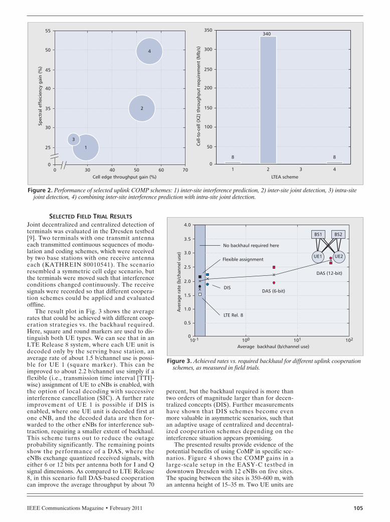
SELECTED FIELD TRIAL RESULTSJoint decentralized and centralized detection ofterminals was evaluated in the Dresden testbed[9]. Two terminals with one transmit antennaeach transmitted continuous sequences of modu-lation and coding schemes, which were receivedby two base stations with one receive antennaeach (KATHREIN 80010541). The scenarioresembled a symmetric cell edge scenario, butthe terminals were moved such that interferenceconditions changed continuously. The receivesignals were recorded so that different coopera-tion schemes could be applied and evaluatedoffline.
The result plot in Fig. 3 shows the averagerates that could be achieved with different coop-eration strategies vs. the backhaul required.Here, square and round markers are used to dis-tinguish both UE types. We can see that in anLTE Release 8 system, where each UE unit isdecoded only by the serving base station, anaverage rate of about 1.5 b/channel use is possi-ble for UE 1 (square marker). This can beimproved to about 2.2 b/channel use simply if aflexible (i.e., transmission time interval [TTI]-wise) assignment of UE to eNBs is enabled, withthe option of local decoding with successiveinterference cancellation (SIC). A further rateimprovement of UE 1 is possible if DIS isenabled, where one UE unit is decoded first atone eNB, and the decoded data are then for-warded to the other eNBs for interference sub-traction, requiring a smaller extent of backhaul.This scheme turns out to reduce the outageprobability significantly. The remaining pointsshow the performance of a DAS, where theeNBs exchange quantized received signals, witheither 6 or 12 bits per antenna both for I and Qsignal dimensions. As compared to LTE Release8, in this scenario full DAS-based cooperationcan improve the average throughput by about 70
percent, but the backhaul required is more thantwo orders of magnitude larger than for decen-tralized concepts (DIS). Further measurementshave shown that DIS schemes become evenmore valuable in asymmetric scenarios, such thatan adaptive usage of centralized and decentral-ized cooperation schemes depending on theinterference situation appears promising.
The presented results provide evidence of thepotential benefits of using CoMP in specific sce-narios. Figure 4 shows the COMP gains in alarge-scale setup in the EASY-C testbed indowntown Dresden with 12 eNBs on five sites.The spacing between the sites is 350–600 m, withan antenna height of 15–35 m. Two UE units are
Figure 2. Performance of selected uplink COMP schemes: 1) inter-site interference prediction, 2) inter-site joint detection, 3) intra-sitejoint detection, 4) combining inter-site interference prediction with intra-site joint detection.
Cell edge throughput gain (%)
Spec
tral
eff
eici
ency
gai
n (%
)
Cel
l-to-
cell
(X2)
thr
ough
put
requ
irem
ent
(Mb/
s)
30
25
00 40 50 60 70
30
35
40
45
50
55
LTEA scheme
2
340
1
8
43
8
50
0
100
150
200
250
300
350
2
4
1
3
Figure 3. Achieved rates vs. required backhaul for different uplink cooperationschemes, as measured in field trials.
Average backhaul (b/channel use)
LTE Rel. 8
DIS
BS1
UE1 UE2
BS2
DAS (6-bit)
DAS (12-bit)
Flexible assignment
No backhaul required here
100 10-1
0.5
Ave
rage
rat
e (b
/cha
nnel
use
)
0
1.0
1.5
2.0
2.5
3.0
3.5
4.0
101 102
IRMER LAYOUT 1/19/11 3:33 PM Page 105

IEEE Communications Magazine • February 2011106
carried on a measurement bus on a 7.5 km lengthroute, as depicted in Fig. 4, which passes throughdifferent kinds of surroundings, including anunderpass, apartment buildings, a train station,and open spaces like parking areas. Convention-al non-cooperative decoding is compared tocooperative joint decoding. Through coopera-tion, average spectral efficiency gains of about20 percent were achieved. In certain areas, how-ever, gains above 100 percent were observed.Furthermore, the variance of achievable rates atdifferent UE positions was reduced, correspond-ing to fairer rate distribution throughout themeasurement area.
CHALLENGESFrom the experience of implementing and test-ing UL COMP, the following key challengeshave become apparent.
Clustering: Suitable clusters of cooperatingbase stations have to be found, which can bedone in a static way or dynamically, as discussedbelow.
Synchronization: Cooperating base stationshave to be synchronized in frequency such thatintercarrier interference is avoided, and in timein order to avoid both intersymbol and intercar-rier interference [10]. The maximum distance ofcooperating base stations is limited since differ-ent propagation delays of different terminalsmay conflict with the guard interval. This aspectmay be compensated through a more complexequalization.
Channel estimation: A large number of eNBsin the COMP cluster in the UL will require alarger number of orthogonal UL pilot sequences.
At some cluster sizes, the COMP gains are out-weighed by capacity losses due to additionalpilot effort.
Complexity: The above mentioned field trialshave been performed using orthogonal frequen-cy-division multiple access (OFDMA) in the UL,as this enables a subcarrier and symbol-wiseMIMO equalization and detection in the fre-quency domain. If single-carrier (SC)-FDMAwas used as in LTE Release 8, equalizationwould be more complex.
Backhaul: It can be a severe issue if central-ized decoding is applied. Hence, adaptive decen-tralized/centralized cooperation appears to be aninteresting option. Furthermore, source codingschemes appear interesting for backhaul com-pression.
DOWNLINKCOORDINATED MULTIPOINT
OVERVIEWBase station cooperation in the DL can alsoimprove average throughput and, more impor-tant, cell edge throughput [2]. 3GPP distinguish-es between the following categories of DLCOMP [11].
Coordinated scheduling/beamforming: Userdata is only available in one sector, the so-calledserving cell, but user scheduling and beamform-ing decisions are made with coordination amongthe sectors.
Joint processing COMP: User data to betransmitted to one terminal is available in multi-ple sectors of the network. A subclass of jointprocessing is joint transmission, where the datachannel to one terminal is simultaneously trans-mitted from multiple sectors.
Both coordinated scheduling/beamformingand joint transmission have been investigatedwithin the EASY-C project.
SELECTED SIMULATION RESULTSCoordinated beam selection [12] and co-scheduling are part of the investigated COMPschemes. Co-scheduling draws its gains frominterference avoidance and is less complex thanDL joint transmission. One approach whichincludes beamforming per cell is presentedhere. Synchronization of the cells is needed;however, there is no strict requirement onphase stability as known from coherent tech-niques. Multicell co-coordinated beamforminghas been assessed in system-level simulationstaking into account the latency for inter-NodeBcommunication.
The method is based on an extended precod-ing matrix index (PMI): the terminals measureand report the PMIs for their own cells (bestcompanion) and additionally the PMIs for theneighboring cells causing the strongest interfer-ence (worst companion) plus the channel qualityinformation for the case that these worst inter-ferers are not used.
The multicell scheduler is based on a dis-tributed approach, with overlapping clusters ofseven neighboring cells each. The scheduling iscoordinated within the clusters. The followingresults are given for four closely spaced antennas
Figure 4. Uplink COMP gains in EASY-C testbed in downtown Dresden.
IRMER LAYOUT 1/19/11 3:33 PM Page 106

at the base station and two UE antennas at 20MHz system bandwidth.
The simulations show significant gains forcoordinated DL scheduling, in particular formobiles at the cell edge. Additionally, thegains were evaluated for different radio chan-nels and different latencies for communicationbetween the sites. As can be observed in Fig.5, 1 ms latency/hop has only a moderateimpact on the gains. Even with highly time-variant channels such as urban macrocell(UMa) at 30 km/h, co-scheduling still providesa sensible improvement. Assuming 6 ms laten-cy per hop, the gains are still preserved forUE velocities up to 3 km/h.
The aggregated additional traffic on the back-haul sums up to approximately 5 Mb/s for 20MHz spectrum; as a result this technique is alsoeconomically attractive.
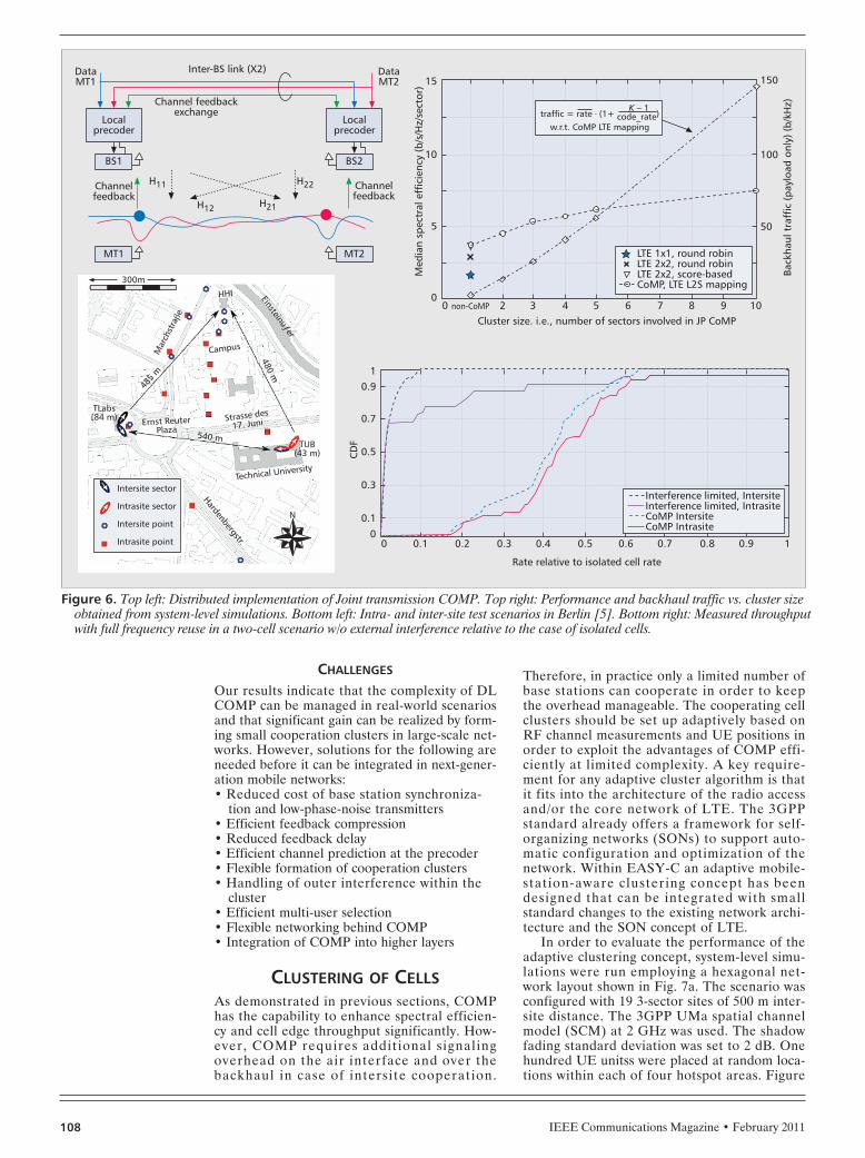
SELECTED FIELD TRIAL RESULTSSince joint transmission is regarded as the mostchallenging CoMP technique from the imple-mentation perspective, it has been implementedin both testbeds to investigate the feasibility ofcoherent transmission for intra- and intersiteCOMP [13, 14]. Significant throughput gainshave been demonstrated for specific interferencescenarios. The same techniques have also beenassessed in wide-area system-level simulations tostudy more complex scenarios. The followingenabling features were essential for the trials:• Sufficient timing and frequency synchro-
nization accuracy: In the trials GPS wasused, although network-based approachessuch as IEEE 1588v2 could also providesufficient accuracy.
• Low-phase-noise radio frequency (RF)oscillators were used.
• Cell-specific reference signals.• Time-stamped CSI feedback.• Synchronous exchange of data and channel
state information (CSI) between eNBs overthe X2 interface.
• Distributed precoding and the provision ofprecoded pilots.An example of the DL COMP experiments
conducted in the Berlin testbed is shown in Fig.7a. A distributed implementation of joint trans-mission has been demonstrated with synchro-nized base stations and cell-specific pilots.Terminals estimate the multicell channel andfeed the CSI back to their serving cells. Base sta-tions exchange CSI as well as data and indepen-dently perform pre-coding with the goal tomaximize the desired signals whilst minimizingmutual interference.
Quantization and compression of the CSI areimportant topics, but outside the scope of thistrial setup. CSI is fed back from the terminalssafely using UL resources at a data rate of 4.6Mb/s. Feedback interval and precoding delay are10 and 20 ms, respectively. The X2 interfacebetween base stations is realized using a 1 Gb/sEthernet connection over cooper, fiber, or free-space optics, depending on the setup. The bidi-rectional load is 300 Mb/s realized with 0.5 mslatency.
Measurements were taken in the laboratory[5] and over the air in both indoor and outdoor
environments (Fig. 6, bottom left). It wasobserved that the interference situation experi-enced at a terminal is indeed critical at the celledge if both base station signals are receivedequally strong on average at full frequencyreuse. Signal and interference links fade inde-pendently, and sometimes the signal is strongerthan the interference, while after a very shortdistance the opposite can be true. This is theorigin of the high outage probabilities observedat the cell edge in the interference-limited case(Fig. 6, bottom right). Once DL COMP isswitched on, significantly higher data rates canbe realized in both cells simultaneously, due tothe mutual interference cancellation. Moreover,the outage probability is remarkably reduced.Our experiments have shown that COMP gainsare significant for simple interference scenarios,and that the implementation challenges can beovercome.
In reality, non-cooperating cells would sur-round the cluster of cooperative cells, leading toa remaining interference floor not yet present inour trials. The presence of such external inter-ference has been studied in wide-area system-level simulations using basically the same COMPconcept also tested in the field. Note that theactive set is found so that in each cell two usersare randomly placed, and each user gets onlyone stream. In all cells, only those user setsrequesting the same cooperation cluster areinvestigated. In Fig. 6 (top right) we observe thatthere is no gain from using explicit CSI feedbackin the serving cell, exploited for multi-user DLbeamforming. Performance is equivalent to afixed grid-of-beams as in LTE Release 8 if theterminal estimates in addition the surroundinginterferers coherently, applies interference rejec-tion combining, and provides implicit frequency-selective feedback on interference-aware PMIand CQI, and the base station applies score-based scheduling [4]. Explicit CSI feedback isuseful for CoMP. With increasing cluster size,the interference floor is reduced and the perfor-mance enhanced accordingly, at the cost of addi-tional effort for overhead and backhaul. Formore details, see [5].
IEEE Communications Magazine • February 2011 107
Figure 5. Downlink co-scheduling: spectral efficiency vs. cell edge throughputfor ITU UMa and SCME radio channels and different backhaul latencies.
Spectral efficiency (b/Hz/sector)
DL spectral efficiency vs. cell edge throughput
1.90
3.00E+055%-il
e C
DF
DL
UE
thro
ughp
ut (
b/s)
4.00E+05
5.00E+05
6.00E+05
7.00E+05
8.00E+05
9.00E+05
1.00E+06
2.00E+052.00 2.10 2.20
alpha 3.0alpha 2.0
alpha 1.0
alpha 0.5
2.30 2.40 2.50 2.60 2.70
3GPP_SCME_1ms3GPP_SCME_6ms3GPP_SCME_baselineITU_UMa_1msITU_UMa_6msITU_UMa_baseline
IRMER LAYOUT 1/19/11 3:33 PM Page 107
IEEE Communications Magazine • February 2011108
CHALLENGES
Our results indicate that the complexity of DLCOMP can be managed in real-world scenariosand that significant gain can be realized by form-ing small cooperation clusters in large-scale net-works. However, solutions for the following areneeded before it can be integrated in next-gener-ation mobile networks:• Reduced cost of base station synchroniza-
tion and low-phase-noise transmitters• Efficient feedback compression• Reduced feedback delay• Efficient channel prediction at the precoder• Flexible formation of cooperation clusters• Handling of outer interference within the
cluster• Efficient multi-user selection• Flexible networking behind COMP• Integration of COMP into higher layers
CLUSTERING OF CELLSAs demonstrated in previous sections, COMPhas the capability to enhance spectral efficien-cy and cell edge throughput significantly. How-ever, COMP requires additional signalingoverhead on the air interface and over thebackhaul in case of intersite cooperation.
Therefore, in practice only a limited number ofbase stations can cooperate in order to keepthe overhead manageable. The cooperating cellclusters should be set up adaptively based onRF channel measurements and UE positions inorder to exploit the advantages of COMP effi-ciently at limited complexity. A key require-ment for any adaptive cluster algorithm is thatit fits into the architecture of the radio accessand/or the core network of LTE. The 3GPPstandard already offers a framework for self-organizing networks (SONs) to support auto-matic configuration and optimization of thenetwork. Within EASY-C an adaptive mobile-station-aware clustering concept has beendesigned that can be integrated with smallstandard changes to the existing network archi-tecture and the SON concept of LTE.
In order to evaluate the performance of theadaptive clustering concept, system-level simu-lations were run employing a hexagonal net-work layout shown in Fig. 7a. The scenario wasconfigured with 19 3-sector sites of 500 m inter-site distance. The 3GPP UMa spatial channelmodel (SCM) at 2 GHz was used. The shadowfading standard deviation was set to 2 dB. Onehundred UE unitss were placed at random loca-tions within each of four hotspot areas. Figure
Figure 6. Top left: Distributed implementation of Joint transmission COMP. Top right: Performance and backhaul traffic vs. cluster sizeobtained from system-level simulations. Bottom left: Intra- and inter-site test scenarios in Berlin [5]. Bottom right: Measured throughputwith full frequency reuse in a two-cell scenario w/o external interference relative to the case of isolated cells.
Mar
chst
raβe Cluster size. i.e., number of sectors involved in JP CoMP
non-CoMP00
Med
ian
spec
tral
eff
icie
ncy
(b/s
/Hz/
sect
or)
Back
haul
tra
ffic
(pa
yloa
d on
ly)
(b/k
Hz)
5
10
150
100
50
15
2 3 4 5 6 7 8 9 10
Rate relative to isolated cell rate
00
CD
F
0.91
0.7
0.5
0.3
0.1
0.9 10.80.70.60.50.40.30.20.1
Interference limited, IntersiteInterference limited, IntrasiteCoMP IntersiteCoMP Intrasite
Channelfeedback
MT1
300m
N
Hardenbergstr.
Technical University
TUB(43 m)
TLabs(84 m)
540 m
Ernst ReuterPlaza
Strasse des17. Juni
Campus
485
m
480 m
HHI Einsteinuƒer
BS1
H11 H22
H12 H21
Localprecoder
DataMT1
DataMT2
MT2
BS2
Channelfeedback
Localprecoder
Inter-BS link (X2)
Channel feedbackexchange
Intersite sector
Intrasite sector
Intersite point
Intrasite point
K – 1traffic = rate ⋅ (1+ code_rate)
w.r.t. CoMP LTE mapping
LTE 1x1, round robinLTE 2x2, round robinLTE 2x2, score-basedCoMP, LTE L2S mapping
IRMER LAYOUT 1/19/11 3:33 PM Page 108

IEEE Communications Magazine • February 2011 109
7b shows the result of the designed clusteringalgorithm, which was configured to obtain theoptimal solution for a disjoint set of clusterswith up to three sectors. The colors representthe different clusters. The clustering algorithmtook only long-term average received powermeasurements from UE into account in casethey were higher than –120 dBm. It is apparentfrom the figure that this concept managed toform clusters around the UE hotspots andavoided clusters in regions where not needed.The mean geometry gain due to adaptive clus-tering was about 6 dB for this scenario com-pared to LTE Release 8.
BACKHAUL FOR COMPARCHITECTURE AND TECHNOLOGIES
COMP approaches need to exchange directinformation between cells, with different require-ments of necessary backhaul throughput andlatency. Intra-site COMP can be realized with-out any impact on backhaul. In the case ofdeployment of remote radio units connected to acentralized baseband processing unit via Ether-net or fiber links, COMP backhaul requirementsshould also be no obstacle.
For connectivity between sites, the logical X2interface could be used. This could either be adirect physical link or a multihop link, depend-ing on the network’s backhaul architecture. Thedelay depends on the network topology, networknode processing delay and line delay (usuallyspeed of light). Gigabit Ethernet speeds of up 10Mb/s and delays of 0.1–20 μs with additionaldelays due to switching equipment. Other suit-able candidates are conventional and millimeter-wave microwave, with speeds up to of 800 Mb/sor 10 Gb/s, respectively, and delays as low as 150μs/hop.
LATENCY REQUIREMENTS
COMP has to be integrated with the hybridautomatic repeat request (HARQ) process; thus,the backhaul latency will put some limits on this,suggesting a maximum latency of 1 ms withoutLTE standard modification.
Another impact of backhaul latency is thatthe exchanged channel information is outdated.For example, a minor performance degradationwas estimated for coordinated scheduling con-sidering a X2 latency of 6 ms. In [15] a DLCOMP capacity gain reduction of 20 percent isestimated for joint transmission with 5 ms back-haul latency at 3 km/h.
CAPACITY REQUIREMENTSCOMP schemes require the exchange of channelstate information, control data, user data, andreceived signals, in a preprocessed or quantizedformat.
As shown earlier and in [16, 17], the backhaulrequirements vary strongly from a few megabitsper second up to 4 Gb/s for different COMPapproaches, considering a 10 MHz LTE X2 link.This also depends on the cluster size. Earlier weshowed an example of how backhaul can bereduced significantly even without major perfor-mance losses.
To conclude, state-of-the-art backhaul tech-nology can support COMP in principle. Howev-er, the cost of additional backhaul and accesscapacity gains has to be balanced in a networkdeployment.
CONCLUSIONS AND OUTLOOKThis article has shown that coordination of cellsin wide-area systems is not only beneficial foraverage spectral efficiency and cell edge data
Figure 7. Cell layout with UE positions and selected clusters: a) no clustering; b) adaptive clustering.
X-Distance (m)
Original CoMP cluster layout and UE positions
-1000
-1000
Y-D
ista
nce
(m)
-500
0
500
1000
-500 0 500 1000X-Distance (m)
Adapted CoMP Cluster Layout and UE Positions
-1000
-1000
Y-D
ista
nce
(m)
-500
0
500
1000
-500 0 500 1000
01
2
34
5
2122
23
2425
26
2728
291011
122223
24
67
8910
113637
38
3940
41 4243
44 4546
47
4849
50
1112
13
1415
161819
201516
17
1213
14
01
2
34
5
2122
23
2425
26
2728
291011
122223
24
67
8910
113637
38
3940
41 4243
44 4546
47
4849
50
1112
13
1415
161819
201516
17
1213
14
IRMER LAYOUT 1/19/11 3:33 PM Page 109

IEEE Communications Magazine • February 2011110
rates, but can also be implemented. COMP wasdemonstrated for uplink and downlink in twotestbeds in urban areas. COMP schemes for theUL range from joint multicell scheduling tomore complex joint detection, and can be cen-tralized or decentralized. In the DL the schemesrange from less complex coordinated schedulingto more challenging joint processing approaches.
From the technical as well as economic pointsof view, intrasite cooperation will be much easierto realize. However, intersite cooperation will beneeded in order to exhaust the full interferencereduction potential of base station cooperation.The combination of joint processing at one sitewith joint scheduling between the sites is ofgreat interest as it provides promising gains withlimited backhaul.
The following challenges needs to beaddressed in order to benefit from the promisingCOMP gains:• Backhaul with low latency and high band-
width. Today’s backhaul technologies cansupport COMP, but more effort is neededto reduce the amount of data exchangedbetween the sites.
• Clustering and multisite scheduling.• Channel estimation and efficient feedback
(for DL COMP).• Synchronization between sites is feasible
today, but the cell area where COMP canbe applied may be limited by the length ofthe cyclic prefix.
• Combination of UL and DL COMP andtheir integration into the LTE standard.This article, and the EASY-C project, have
already given some answers on COMP. Ongoingefforts to address the challenges in the researchcommunity — such as the ARTIST4G projectand 3GPP standardization — are important togain more insight into achievable spectral effi-ciency gains and the complexity of differentapproaches.
ACKNOWLEDGMENTThe authors acknowledge the excellent coopera-tion of all project partners within the EASY-Cproject and the support of the German FederalMinistry of Education and Research (BMBF).
REFERENCES[1] P. Marsch, S. Khattak, and G. Fettweis, “A Framework
for Determining Realistic Capacity Bounds for Distribut-ed Antenna Systems,” Proc. IEEE Info. Theory Wksp.‘06, Chengdu, China, Oct. 22–26, 2006.
[2] K. M. Karakayli, G. J. Foschini, and R. A. Valenzuela.“Network Coordination for Spectrally Efficient Commu-nications in Cellular Systems,” IEEE Wireless Commun.,vol. 13, no. 4, Aug. 2006, pp. 56–61.
[3] P. Marsch and G. Fettweis, “On Multi-Cell CooperativeTransmission in Backhaul-Constrained Cellular Systems,”Annales des Télécommun., vol. 63, no. 5–6, May 2008.
[4] V. Jungnickel et al., “Interference Aware Scheduling inthe Multiuser MIMO-OFDM Downlink,” IEEE Commun.Mag., vol. 47, no. 6, June 2009.
[5] V. Jungnickel et al., “Field Trials using CoordinatedMulti-Point Transmission in the Downlink,” 3rd IEEEInt’l. Wksp. Wireless Distrib. Net., IEEE PIMRC, Sept.2010.
[6] P. Marsch, Coordinated Multi-Point under a ConstrainedBackhaul and Imperfect Channel Knowledge, Ph.D. the-sis.
[7] A. Müller and P. Frank, “Cooperative Interference Pre-diction for Enhanced Link Adaptation in the 3GPP LTEUplink,” IEEE VTC–Spring, 2010.
[8] A. Müller and P. Frank, “Performance of the LTE Uplinkwith Intra-Site Joint Detection and Joint Link Adapta-tion,” IEEE VTC–Spring, 2010.
[9] M. Grieger et al., “Field Trial Results for a CoordinatedMulti-Point (CoMP) Uplink in Cellular Systems,” Proc.ITG/IEEE Wksp. Smart Antennas ‘10, Bremen, Germany,Feb. 23–24, 2010.
[10] V. Kotzsch and G. Fettweis. “Interference Analysis inTime and Frequency Asynchronous Network MIMOOFDM Systems,” IEEE WCNC ‘10, Sydney, Australia,Apr. 18–21, 2010.
[11] 3GPP TR 36.814, “Further Advancements for E-UTRAPhysical Layer Aspects,” Release 9, v. 9.0.0, Mar. 2010.
[12] J. Giese and M. A. Awais, “Performance Upper Boundsfor Coordinated Beam Selection in LTE-Advanced,”Proc. ITG/IEEE Wksp. Smart Antennas ‘10, Bremen, Ger-many, Feb. 23–24, 2010.
[13] G. Fettweis et al., “Field Trial Results for LTE-AdvancedConcepts,” Proc. IEEE ICASSP ‘10, Dallas, TX, Mar.14–19, 2010.
[14] L. Thiele, V. Jungnickel, and T. Haustein, “InterferenceManagement for Future Cellular OFDMA Systems UsingCoordinated Multi-Point Transmission,” IEICE Trans.Commun., Special Issue on Wireless Distributed Net-works, Dec. 2010.
[15] S. Brueck et al., “Centralized Scheduling for Joint-Transmission Coordinated Multi-Point in LTE-Advanced,”Proc. ITG/IEEE Wksp. Smart Antennas ‘10, Bremen, Ger-many, Feb. 23–24, 2010.
[16] C. Hoymann, L. Falconetti, and R. Gupta, “DistributedUplink Signal Processing of Cooperating Base Stationsbased on IQ Sample Exchange,” Proc. IEEE ICC ‘09,Dresden, Germany, June 14–18, 2009.
[17] L. Falconetti, C. Hoymann, and R. Gupta, “DistributedUplink Macro Diversity for Cooperating Base Stations,”Proc. IEEE ICC ‘09, Dresden, Germany, June 14–18,2009.
ADDITIONAL READING[1] R. Irmer et al., “Multisite Field Trial for LTE and
Advanced Concepts,” IEEE Commun. Mag., vol. 47, no.2, Feb. 2009, pp. 92–98.
BIOGRAPHIESRALF IRMER [SM] ([email protected]) received hisDipl-Ing. and Dr.-Ing. degrees from Technische UniversitätDresden in 2000 and 2005, respectively. He joined Voda-fone Group R&D in 2005, where he leads the WirelessAccess Group, which is responsible for evolution of LTE,WiFi, and other technologies, and defining Vodafone’sfuture network architecture. Before, he worked for fiveyears as a research associate at TU Dresden. He holds sev-eral patents, and has published more than 30 conferenceand journal publications. He had a leading role in severalresearch projects, including WIGWAM, WINNER, and EASY-C. He is a member of VDE and IET.
HEINZ DROSTE ([email protected]) received his Dipl.-Ing degree 1991 from the Open University, Hagen. Sincethen he has been working for Deutsche Telekom at a vari-ety of mobile communication related R&D projects. Anten-nas and radio wave propagation belong to his knowledgefield as well as system-level simulation and radio networkplanning. More recently he extended his expertise to thefield of techno-economical evaluations. In the frameworkof EASY-C he coordinates the partner activities in WorkingGroup 1, “Algorithm and Concepts.”
PATRICK MARSCH ([email protected]) received hisDipl.-Ing. and Dr.-Ing. degrees from Technische UniversitätDresden in 2004 and 2010, respectively, after completingan apprenticeship at Siemens AG and studying at the TUDresden and McGill University, Montréal, Canada. After aninternship with Philips Research East Asia in Shanghai, P.R.China, he joined the Vodafone Chair in 2005. He is thetechnical project coordinator of EASY-C, and is currentlyheading a research group on the analysis and optimizationof cellular systems.
MICHAEL GRIEGER received his Dipl.-Ing. from DHBW Stuttgartin 2005 and his M.Sc. from the Technische UniversitätDresden in March 2009. In 2008, funded by the HerbertQuandt/ALTANA Foundation, he studied at CTU, Prague.During his Master’s thesis, he conducted research in Prof.John Cioffi’s group at Stanford University on multicell sig-
COMP schemes for
the uplink range
from joint multi-cell
scheduling to more
complex joint
detection, and can
be centralized or
decentralized. In the
downlink, the
schemes range from
less complex
coordinated
scheduling to more
challenging joint
processing
approaches.
IRMER LAYOUT 1/19/11 3:33 PM Page 110
IEEE Communications Magazine • February 2011 111
nal processing, which continues to be his major researchfocus today. An aspect of his research is the comparison ofinformation theoretic results to those of the “real world”using field trials.
GERHARD FETTWEIS [F] ([email protected]) earnedhis Dipl.-Ing. (1986) and Ph.D. (1990) degrees from AachenUniversity of Technology (RWTH), Germany. From 1990 to1991 he was a visiting scientist at the IBM AlmadenResearch Center, San Jose, California, working on signalprocessing for disk drives. From 1991 to 1994 he was withTCSI Inc., Berkeley, California, responsible for signal proces-sor development. Since 1994 he holds the Vodafone Chairat TU Dresden. He is coordinating the research projectEASY-C.
HANS-PETER MAYER ([email protected])received his Ph.D. degree in physics from the University ofTübingen in 1987. He joined Alcatel-Lucent and worked onhigh-speed optoelectronic and WDM components until1995. From 1996 to 1999, he has been responsible forearly UMTS system studies, followed by the realization offirst UMTS and HSPA trial systems. Within Bell Labs, he iscurrently responsible for the Advanced MAC departmentwith a focus on projects related to LTE-Advanced.
STEFAN BRUECK ([email protected]) studied mathe-matics and electrical engineering at the University of Tech-nology Darmstadt, Germany, and Trinity College Dublin,Ireland. He received his Dipl.-Math. and Dr.-Ing. degrees in
1994 and 1999, respectively. From 1999 to 2008 he wasworking for Lucent Technologies and Alcatel-Lucent in BellLabs and UMTS Systems Engineering, where he was respon-sible for the MAC layer design of the HSPA base station. InMay 2008 he joined Qualcomm Germany and currentlyleads the Radio Systems R&D activities in the CorporateR&D Centre Nuremberg. He is involved in several researchprojects on LTE-Advanced.
LARS THIELE [S‘05] received his Dipl.-Ing. (M.S.) degree inelectrical engineering from TU Berlin in 2005. Currently heis working towards his Dr.-Ing. (Ph.D.) degree at theFraunhofer Heinrich Hertz Institute (HHI), Berlin. He hascontributed to receiver and transmitter optimization underlimited feedback, performance analysis for MIMO trans-mission in cellular ODFM systems, and fair resource alloca-tion. He has authored and co-authored about 40conference and journal papers in the area of mobile com-munications.
VOLKER JUNGNICKEL [M‘99] ([email protected]) received a Dr.rer. nat. (Ph.D.) degree in physics from Humboldt Univer-sität zu Berlin in 1995. He worked on semiconductor quan-tum dots and laser medicine and joined HHI in 1997. He isa lecturer at TU Berlin and head of the cellular radio teamat HHI. He has contributed to high-speed indoor wirelessinfrared links, 1 Gb/s MIMO-OFDM radio transmission, andinitial field trials for LTE and LTE-Advanced. He hasauthored and co-authored more than 100 conference andjournal papers on communications engineering.
IRMER LAYOUT 1/19/11 3:33 PM Page 111