Embed Size (px)
Citation preview

University of South CarolinaScholar Commons
Theses and Dissertations
1-1-2013
Coordinated Control of Power ElectronicConverters in an Autonomous MicrogridGholamreza DehnaviUniversity of South Carolina
Follow this and additional works at: https://scholarcommons.sc.edu/etd
Part of the Electrical and Electronics Commons
This Open Access Dissertation is brought to you by Scholar Commons. It has been accepted for inclusion in Theses and Dissertations by an authorizedadministrator of Scholar Commons. For more information, please contact [email protected].
Recommended CitationDehnavi, G.(2013). Coordinated Control of Power Electronic Converters in an Autonomous Microgrid. (Doctoral dissertation). Retrievedfrom https://scholarcommons.sc.edu/etd/2175
COORDINATED CONTROL OF POWER ELECTRONIC CONVERTERS IN AN
AUTONOMOUS MICROGRID
by
Gholamreza Dehnavi
Bachelor of Science
University of Tehran, 1997
Master of Science
Iran University of Science and Technology, 2000
Submitted in Partial Fulfillment of the Requirements
For the Degree of Doctor of Philosophy in
Electrical Engineering
College of Engineering and Computing
University of South Carolina
2013
Accepted by:
Herbert L. Ginn III, Major Professor
Roger A. Dougal, Committee Member
Charles W. Brice, Committee Member
Edward P. Gatzke, Committee Member
Lacy Ford, Vice Provost and Dean of Graduate Studies

ii
© Copyright by Gholamreza Dehnavi, 2013
All Rights Reserved.

iii
DEDICATION
To Laleh, my dear wife, for her patience and support during this work
AND
To Alborz, my lovely son, for the happiness he brought us.

iv
ACKNOWLEDGEMENTS
First and foremost, I wish to acknowledge the assistance and guidance of my
advisor, Dr. Herbert Ginn, for his mentoring efforts during this research. His positive
reinforcement along with belief and patience led me to come up with this work. I will
always remember his support and friendliness.
I also wish to thank my advisory committee members, Dr. Roger Dougal, Dr.
Charles Brice, and Dr. Edward Gatzke, for their time, interest, helpful comments, and
insightful questions.
I would like to acknowledge the funding source that made my Ph.D. work
possible. My work was supported by the U.S. Office of Naval Research.
Last but not least, I thank my lovely wife and sweet son who made this work
possible by their support and encouragement. My parents receive my deepest gratitude
and love for their dedication, support and patience during my life.

v
ABSTRACT
Advances in power electronics and generation technologies have increased the
viability of distributed generation systems. A microgrid is a special category of
distributed generation systems that is distinguished by its size and the ability to operate
independently as an islanded system. As long as a microgrid is connected to a large grid,
quality of the voltage is supported by the main grid and each power source connected to
the microgrid generates independently. In contrast, in the islanded operation of
microgrids and in electrical islands such as shipboard distribution systems, dynamics are
strongly dependent on the connected sources and on the power regulation control of the
grid interfacing converters. In this mode, power sources in a microgrid should be
controlled in coordination with each other so that a stable balanced three-phase sinusoidal
voltage is provided.
In many cases, energy sources in a microgrid are interfaced through power
electronic converters. A higher degree of controllability of converters as compared to
electrical machines allows for the possibility of ancillary functions for power quality
improvement when converters have unused capacity. The present work proposes a
cooperative control approach for converters in a microgrid in which, by efficiently
utilizing power converters in response to load demand and required ancillary functions,
the operation of the microgrid is optimized. Efficient utilization of power converters is
determined by a management system according to an optimization function.

vi
A higher level control is also proposed in this work which exchanges set-point
values with local controls through low bandwidth communication links in order to
eliminate voltage magnitude deviation, frequency error, imbalance and harmonic
distortion at a load bus.
Each of a converter’s tasks can be expressed in terms of current components
measured at a converter’s point of connection to the system. Thus, current-based
coordination of a microgrid is performed through a decomposition of current into
orthogonal components. Different components of a converter’s output current are
controlled independently in order to enable optimization of various parameters of a
microgrid. All converters in the system are considered including converters that are not
actively interfacing an electrical energy source to the grid.
Some power units in microgrids are controlled to generate active current
according to a reference made by an internal control system such as MPPT1 system or
SOC2 controller. The presented cooperative control approach is expanded to allow these
units to supply active current in accordance with the local reference while they also
contribute to generation of non-active currents in coordination with other units.
Simulation results verify the benefits of the control approach developed here in
both coordination and voltage quality improvement. Thus, the method allows operation
of the microgrid to be improved by utilizing the available converters to the fullest extent
possible. This reduces the need to connect additional resources to the microgrid.
1 Maximum Power Point Tracking
2 State Of Charge

vii
TABLE OF CONTENTS
DEDICATION ....................................................................................................................... iii
ACKNOWLEDGEMENTS........................................................................................................ iv
ABSTRACT ........................................................................................................................... v
TABLE OF CONTENTS ......................................................................................................... vii
LIST OF TABLES ....................................................................................................................x
LIST OF FIGURES ................................................................................................................. xi
CHAPTER I: INTRODUCTION TO COORDINATED CONTROL OF
CONVERTERS IN AUTONOMOUS MICROGRIDS ................................................. 1
1.1 PROBLEM DESCRIPTION ....................................................................................... 3
1.2 LITERATURE REVIEW ........................................................................................... 5
1.3 OBJECTIVES ........................................................................................................... 16
1.4 ORGANIZATION OF THE DISSERTATION........................................................ 18
CHAPTER II: POWER SHARING AMONG CONVERTERS IN AN
AUTONOMOUS MICROGRID ................................................................................... 20
2.1 DROOP CONTROL FOR ACTIVE AND REACTIVE POWER SHARING......... 22
2.2 EFFECT OF LINE RESISTANCE ........................................................................... 24
2.3 INACCURACY OF REACTIVE POWER CONTROL .......................................... 28
2.4 EXTENSION OF DROOP CONTROL TO ALL POWER COMPONENTS ......... 29
2.5 SIMULATIONS ....................................................................................................... 36
2.6 SUMMARY .............................................................................................................. 41
viii
CHAPTER III: CURRENT-BASED DROOP CONTROL AND CPC POWER
THEORY ......................................................................................................................... 42
3.1 CPC POWER THEORY........................................................................................... 42
3.2 CONTROL OF ACTIVE AND REACTIVE COMPONENTS ............................... 46
3.3 COORDINATED CONTROL OF HARMONIC COMPONENT OF THE LOAD
CURERNT ........................................................................................................................ 47
3.4 COORDINATED CONTROL OF UNBALANCED COMPONENT OF THE
LOAD CURERNT ............................................................................................................ 48
3.5 SIMULATIONS ....................................................................................................... 51
3.6 SUMMARY .............................................................................................................. 57
CHAPTER IV: POWER QUALITY IMPROVEMENT BY SECONDARY
CONTROL LOOP .......................................................................................................... 58
4.1 ALLEVIATION OF VOLTAGE MAGNITUDE AND FREQUENCY DEVIATION
AT THE LOAD BUS........................................................................................................ 59
4.2 VOLTAGE BALANCING AT THE LOAD BUS ................................................... 60
4.3 REDUCTION OF VOLTAGE DISTORTION AT THE LOAD BUS..................... 62
4.4 SIMULATIONS ....................................................................................................... 64
4.5 SUMMARY .............................................................................................................. 73
CHAPTER V: DESIGN OF THE CONTROL PARAMETERS AND STABILITY
ANALYSIS ...................................................................................................................... 74
5.1 CURRENT CONTROL LOOP................................................................................. 74
5.2 VOLTAGE CONTROL LOOP ................................................................................ 76
5.3 VIRTUAL IMPEDANCE LOOP ............................................................................. 81
5.4 DROOP CONTROL LOOP ...................................................................................... 83
5.5 SECONDARY CONTROL LOOP ........................................................................... 84
5.6 SUMMARY .............................................................................................................. 87
ix
CHAPTER VI: MICROGRID OPTIMIZATION IN THE PRESENCE OF STORAGE, PV AND WIND POWER UNITS............................................................. 88
6.1 POWER UNITS WITH LOCALLY CONTROLLED ACTIVE POWER .............. 89
6.2 PROPOSED CONTROL SCHEME ......................................................................... 93
6.3 SIMULATION RESULTS ....................................................................................... 97
6.4 SUMMARY ............................................................................................................ 104
CHAPTER VII: MICROGRID POWER MANAGEMENT SYSTEM .................. 106
7.1 OPTIMIZATION FUNCTIONS............................................................................. 108
7.2 CONSIDERED OPTIMIZATION FUNCTION .................................................... 111
7.3 MATHEMATICAL REPRESENTATION ............................................................ 112
7.4 SIMULATION ........................................................................................................ 115
7.5 SUMMARY ............................................................................................................ 121
CHAPTER VIII: CONCLUSIONS AND FUTURE WORK.................................... 122
8.1 CONCLUSION ....................................................................................................... 122
8.2 FUTURE WORK .................................................................................................... 124
REFERENCES .............................................................................................................. 126

x
LIST OF TABLES
Table 2.1. Parameters of the simulated system. .................................................................38
Table 3.1. Parameters of the simulated system. .................................................................53
Table 6.1. Parameters of the simulated system. .................................................................98
Table 7.1. Parameters of the simulated system. ...............................................................116
xi
LIST OF FIGURES
Figure 1.1. General architecture of a microgrid ................................................................. 3
Figure 1.2. Microgrid problems that are solved in this dissertation ................................... 4
Figure 1.3. Architecture of the control system ................................................................... 6
Figure 1.4. Application of droop control for voltage harmonic filtering by parallel
APFs ................................................................................................................................... 8
Figure 1.5. Block diagram of the hierarchical control of AC microgrid. (a) primary and
secondary control (b) tertiary control and synchronization loop .................................... 13
Figure 1.6. Energy management system for microgrid .................................................... 14
Figure 1.7. Voltage and current P + Resonant controller of a voltage source inverter ..... 15
Figure 1.8. Block diagram of the closed loop voltage source inverter ............................ 15
Figure 1.9. Objective plan for optimization of microgrid operation and power quality
increase.............................................................................................................................. 18
Figure 2. 1. Current control of converters for grid-connected mode of operation........... 20
Figure 2. 2. Nested control loops for converters in an autonomous microgrid................ 21
Figure 2. 3. Distributed control of power components in coordination with other
converters .......................................................................................................................... 22
Figure 2. 4. Equivalent circuit of a DG unit connected to the common ac bus ................ 22
Figure 2. 5. frequency and voltage droop for active and reactive power control ............. 24
Figure 2. 6. Sharing load power by means of droop controls. a) Active Power
b) Reactive power ............................................................................................................. 24
Figure 2. 7. Block diagram of the virtual impedance loop ............................................... 26
Figure 2. 8. Negative resistive impedance implementation .............................................. 28
Figure 2. 9. Implemented virtual impedance ................................................................... 31
xii
Figure 2. 10. Realization of the virtual impedance ........................................................... 31
Figure 2. 11. Singe line diagram of a microgrid model .................................................... 32
Figure 2. 12. Equivalent circuit of the circuit in Figure 2.11............................................ 33
Figure 2. 13. A simple microgrid considered for power sharing simulations ................... 36
Figure 2. 14. Local control system of each converter ....................................................... 37
Figure 2. 15. Sharing of active current between two converters with the ratio of ½ ........ 39
Figure 2. 16. Sharing of reactive current between two converters with the ratio of ½ ..... 39
Figure 2. 17. Sharing of harmonic current between two converters with the ratio
of 2/1 ................................................................................................................................. 40
Figure 2. 18. Sharing of Unbalance current between two converters with the
ratio of ½ ........................................................................................................................... 40
Figure 3. 1. Equivalent model of a load supplied by a three-phase voltage source .......... 43
Figure 3. 2. Current-based droop characteristics for active and reactive components ..... 46
Figure 3. 3. Computation of voltage and current fundamental phasor based on RDFT ... 47
Figure 3. 4. Implementation of harmonic and fundamental virtual impedances .............. 48
Figure 3. 5. Simulated microgrid for current components sharing ................................... 52
Figure 3. 6. Block diagram of the local control system ................................................... 53
Figure 3. 7. Active current sharing between two converters with the ratio of 1/2 ............ 54
Figure 3. 8. Reactive current sharing between two converters with the ratio of ½ .......... 55
Figure 3. 9. Harmonic current sharing between two converters with the ratio of 2/1 ...... 55
Figure 3. 10. Unbalance current sharing between two converters with the ratio of 1/2 ... 56
Figure 3. 11. Three phase voltages at load bus at the time of load switching .................. 56
Figure 4. 1. Voltage magnitude and frequency control loop ............................................ 60
Figure 4. 2. Voltage balancing at load bus along with control of unbalance load
sharing ............................................................................................................................... 63
Figure 4. 3. THD minimization at load bus by secondary control .................................... 64

xiii
Figure 4. 4. configuration of the simulated system ........................................................... 65
Figure 4. 5. Sharing of active power between the two converters with ratio of 1/2 ......... 66
Figure 4. 6. Sharing of reactive power between the two converters with ratio of 1/2 ...... 66
Figure 4. 7. Sharing of harmonic current between the two converters with ratio of 2/1 .. 67
Figure 4. 8. Sharing of unbalanced current between the two converters with ratio of ½ . 67
Figure 4. 9. Reinstatement of voltage magnitude at Load bus by the secondary control . 67
Figure 4. 10. Frequency correction by the secondary control ........................................... 68
Figure 4. 11. Elimination of negative sequence voltage at load bus by secondary
control ............................................................................................................................... 68
Figure 4. 12. THD of the voltage at load bus before implementation of the secondary
control ............................................................................................................................... 68
Figure 4. 13. Reduction of Voltage THD by the secondary control ................................. 69
Figure 4. 14. Three phase voltages at load bus during and after load switching .............. 69
Figure 4. 15. Sharing of active current between the two converters with ratio of 1/2 ...... 70
Figure 4. 16. Sharing of reactive current between the two converters with ratio of 1/2... 70
Figure 4. 17. Sharing of harmonic current between the two converters with ratio
of 2/1 ................................................................................................................................. 70
Figure 4. 18. Sharing of unbalanced current between the two converters
with ratio of 1/2 ................................................................................................................. 71
Figure 4. 19. Reinstatement of voltage magnitude at load bus by secondary control ...... 71
Figure 4. 20. Correction of frequency at load bus by secondary control .......................... 71
Figure 4. 21. Elimination of negative sequence component of the voltage at load bus .... 72
Figure 4. 22. THD of the voltage at load bus when secondary control is not
implemented ...................................................................................................................... 72
Figure 4. 23. THD of the voltage at load bus after secondary control is implemented .... 72
Figure 4. 24. Improvement of quality indices of the voltage at load bus - three phase
voltages ............................................................................................................................. 73
Figure 5. 1. Current controller design for a converter not connected to an active grid .... 75

xiv
Figure 5. 2. Comparison of two current controllers, a) PI controller b) Deadbeat
controller ........................................................................................................................... 75
Figure 5. 3. Configuration of the voltage controller ......................................................... 76
Figure 5. 4. Voltage and current controller loops with converter model .......................... 76
Figure 5. 5. Bode plot of voltage controller ...................................................................... 79
Figure 5. 6. Zero poles of voltage control closed loop system ......................................... 80
Figure 5. 7. Zero poles of the discretized voltage control closed loop system ................. 80
Figure 5. 8. Response of the designed PI voltage controller ............................................ 81
Figure 5. 9. Response of deadbeat voltage controller for this system .............................. 81
Figure 5. 10. Virtual impedance loop ............................................................................... 82
Figure 5. 11. Droop control loop....................................................................................... 83
Figure 5. 12. Secondary control loop ................................................................................ 85
Figure 5. 13. Entire Control block diagram of the system ................................................ 85
Figure 6. 1. PhotoVoltaic power source............................................................................ 90
Figure 6. 2. Wind power source ........................................................................................ 91
Figure 6. 3. Battery Storage unit ....................................................................................... 92
Figure 6. 4. Output active current control loop - Reference directly sent to interface
inverter .............................................................................................................................. 95
Figure 6. 5. DC voltage control loop - Reference sent to front-end converter ................. 95
Figure 6. 6. Entire local control system - Reference sent to interface inverter ................. 96
Figure 6. 7. Entire local control system - Reference sent to front-end converter ............. 97
Figure 6. 8. The simulated microgrid................................................................................ 98
Figure 6. 9. Active currents of the two sources and MPPT command for the
PV source ........................................................................................................................ 100
Figure 6. 10. Sharing of reactive current equally between the two sources ................... 100
Figure 6. 11. Sharing of harmonics between the two sources; PV interface converter
generates twice as the other interface converter ............................................................. 101
xv
Figure 6. 12. Sharing of unbalance current between the two sources; PV interface
converter generates half as much as the other interface converter ................................. 101
Figure 6. 13. Reinstatement of voltage magnitude at load bus by secondary control .... 102
Figure 6. 14. Correction of the frequency at load bus by secondary control .................. 102
Figure 6. 15. Control of DC bus voltage by the inverter under load switching and
variation of active power injection by front-end converter............................................. 103
Figure 6. 16. Active power of the two sources under load switching and MPPT
command variation.......................................................................................................... 103
Figure 7. 1. Independent sharing of each current component ......................................... 106
Figure 7. 2. Simplified model of a microgrid used for the simulation............................ 115
Figure 7. 3. Active current sharing among sources along with MPPT command for
source 2 ........................................................................................................................... 118
Figure 7. 4. Reactive current sharing among sources based on the solution of
optimization function ...................................................................................................... 118
Figure 7. 5. Harmonic current sharing among sources ................................................... 119
Figure 7. 6. Unbalanced load sharing among sources..................................................... 119
Figure 7. 7. Reinstatement of voltage magnitude at load bus ......................................... 120
Figure 7. 8. Correction of the frequency ......................................................................... 120
1
CHAPTER I
INTRODUCTION TO COORDINATED CONTROL OF CONVERTERS IN AUTONOMOUS
MICROGRIDS
The world is at the edge of a major shift in the paradigm of electrical energy generation,
transmission, distribution and storage, by moving from existing, centralized generation
towards DER3. The new paradigm has the potential to result in higher stability margins
and better reliability, reduction of transmission lines power loss, power quality increase,
ability to shift peak loads, etc. Smart grid technologies help utilities to operate, control,
and maintain DER as well as interconnect them to the main grid. In the new paradigm of
the grid, the complexity of technical tasks have changed from dealing with local SCADA4
data into a variety of massive field data collection, that allows a more comprehensive
view of the power system status, energy flows, hierarchical control, asset management,
equipment conditions etc. A Microgrid is a localized grouping of DER and loads that has
the capability of islanding and operating independently from the grid as well as grid-
connected mode of operation. Smart technologies bring about the possibility of a smart
microgrid. A smart microgrid typically integrates the following components [1].
a) Power plants capable of meeting local demand as well as feeding the unused
energy back to the electricity grid. Such power plants are often renewable
3 Distributed Energy Resources
4 Supervisory Control And Data Acquisition

2
sources of energy, such as wind, sun, and biomass.
b) It services a variety of loads, including residential, office and industrial loads.
c) It makes use of local and distributed power-storage capability to smooth out the
intermittent performance of renewable energy sources.
d) It incorporates smart meters and sensors capable of measuring a multitude of
consumption parameters (e.g., active power, reactive power, voltage, current, harmonics,
unbalanced current and so on) with acceptable precision and accuracy.
e) It incorporates a communication infrastructure that enables system components to
exchange information and commands securely and reliably.
f) It incorporates smart terminations, loads, and appliances capable of
communicating their status and accepting commands to adjust and control their
performance and service level based on user and/or utility requirements.
g) It incorporates an intelligent core, composed of integrated networking, computing,
and communication infrastructure elements, that appears to users in the form of an
Energy Management System that allows command and control on all nodes of the
network.
In many cases the energy sources in a microgrid are interfaced through power
electronic converters. The controllability of instantaneous output current/voltage of
power converters has caused these converters to be used in different applications. Output
current of the sources that include interface converters can be controlled with more
degrees of freedom. In order to avoid instability in the system and to increase the
efficiency of the microgrid operation, all of the converters in a microgrid should be
controlled in coordination with each other.
3
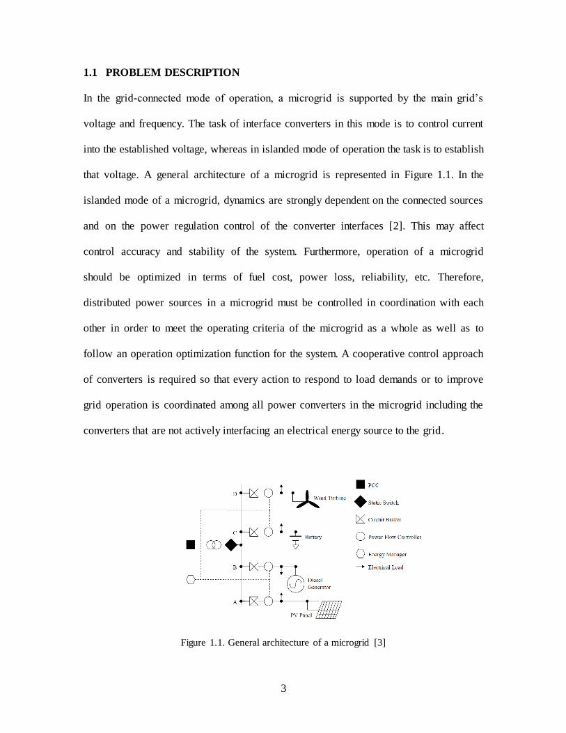
1.1 PROBLEM DESCRIPTION
In the grid-connected mode of operation, a microgrid is supported by the main grid’s
voltage and frequency. The task of interface converters in this mode is to control current
into the established voltage, whereas in islanded mode of operation the task is to establish
that voltage. A general architecture of a microgrid is represented in Figure 1.1. In the
islanded mode of a microgrid, dynamics are strongly dependent on the connected sources
and on the power regulation control of the converter interfaces [2]. This may affect
control accuracy and stability of the system. Furthermore, operation of a microgrid
should be optimized in terms of fuel cost, power loss, reliability, etc. Therefore,
distributed power sources in a microgrid must be controlled in coordination with each
other in order to meet the operating criteria of the microgrid as a whole as well as to
follow an operation optimization function for the system. A cooperative control approach
of converters is required so that every action to respond to load demands or to improve
grid operation is coordinated among all power converters in the microgrid including the
converters that are not actively interfacing an electrical energy source to the grid.
Figure 1.1. General architecture of a microgrid [3]
4
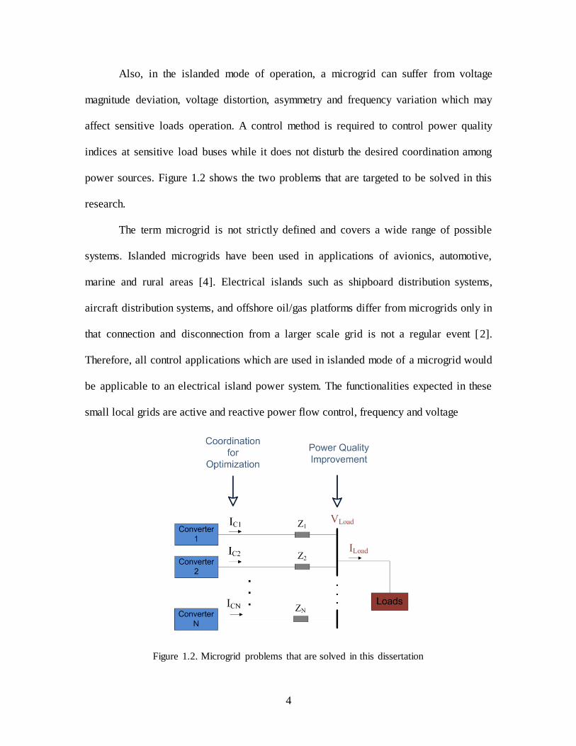
Also, in the islanded mode of operation, a microgrid can suffer from voltage
magnitude deviation, voltage distortion, asymmetry and frequency variation which may
affect sensitive loads operation. A control method is required to control power quality
indices at sensitive load buses while it does not disturb the desired coordination among
power sources. Figure 1.2 shows the two problems that are targeted to be solved in this
research.
The term microgrid is not strictly defined and covers a wide range of possible
systems. Islanded microgrids have been used in applications of avionics, automotive,
marine and rural areas [4]. Electrical islands such as shipboard distribution systems,
aircraft distribution systems, and offshore oil/gas platforms differ from microgrids only in
that connection and disconnection from a larger scale grid is not a regular event [2].
Therefore, all control applications which are used in islanded mode of a microgrid would
be applicable to an electrical island power system. The functionalities expected in these
small local grids are active and reactive power flow control, frequency and voltage
Figure 1.2. Microgrid problems that are solved in this dissertation

5
stability, black start operation, active power flow capabilities and storage energy
management among others [5]. Optimization of microgrid operation requires the
functionality of control over harmonics and unbalanced power flow as well.
In AC microgrids, there are four major power components, i.e. active, reactive,
harmonic, and unbalance components that need to be coordinated. The focus of this
dissertation will be on this type of microgrid. For DC microgrids, there is only one power
component to control i.e. active component which results in simplicity of the control
system compared with the AC microgrid case. Also power quality indices of AC voltage
are more numerous as compared to DC. Thus, AC microgrids are the focus of this
dissertation with the expectation that the results are directly extendable to DC microgrids.
1.2 LITERATURE REVIEW
Several methods for control of converters in a microgrid have been proposed in
the literature. Some of the authors’ contribution to converters control in microgrids is
distributed compensation, some aim at increase of power quality indices, while others’
attention is on power sharing among converters. In general, cooperative control of
converters in a microgrid can either be central or decentralized, disregarding master-slave
control of converters in microgrids for which only a few papers can be found. For each
control method, expansion of the control system has been investigated in the literature
and some improvements have been proposed.
1.2.1 Control of converters in a microgrid – central control of distributed
compensators
In large scale grids compensators connected to the grid are designed to suit local
needs assuming no interactions with the rest of the network, however, in a microgrid
6
distributed compensators interact with each other and with the rest of the network. In
such a context a cooperative control approach of interface power converters and any
other Electronic Power Processor acting in the grid is required. Every action to improve
grid operation (power flow control, voltage support, unbalance compensation, harmonic
mitigation) must be coordinated among all electronic power processors acting in a
microgrid including interface power converters, Active Power Filters, Static Var
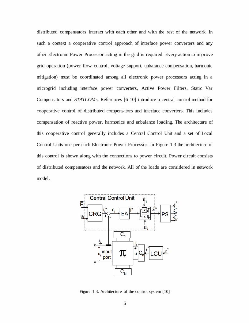
Compensators and STATCOMs. References [6-10] introduce a central control method for
cooperative control of distributed compensators and interface converters. This includes
compensation of reactive power, harmonics and unbalance loading. The architecture of
this cooperative control generally includes a Central Control Unit and a set of Local
Control Units one per each Electronic Power Processor. In Figure 1.3 the architecture of
this control is shown along with the connections to power circuit. Power circuit consists
of distributed compensators and the network. All of the loads are considered in network
model.
Figure 1.3. Architecture of the control system [10]

7
The measurement point of central control is PCC1 which provides reference
values for all local control units. The aim of the control is to make it possible the
exploitation of both quasi-stationary and dynamic compensators. In this sense, based on
the characteristics of different components of current to be compensated, and also
considering the speed of each type of compensator the compensation is shared between
units. Other factors such as compensator’s power rating, distance between the
compensator and PCC, and workload of each compensator is also considered in sharing
of the duties. Quasi stationary compensators are used to take care of parts of the workload
of the dynamic compensators and free their capacity to be used when required. Notice
that with this strategy, a high bandwidth communication is required especially when
harmonics and transient compensation is part of the work. Also, since the configuration
of the system is not generally known, an identification process is essential to evaluate the
voltage and angle difference between PCC and the installation point of each
compensator.
1.2.2 Control of converters in a microgrid – decentralized control of
converters
Central control and master-slave control of power sources rely on communication
for reliable operation. Control commands solely based on local measurements exhibit
superior redundancy and reliability, where they can only be achieved at the price of
permitting a small error. These controls have only proportional controller for frequency
and amplitude of voltage lacking any form of integral control. Due to the small error,
these techniques are generally denoted as droop control methods.
1 Point of Common Coupling
8
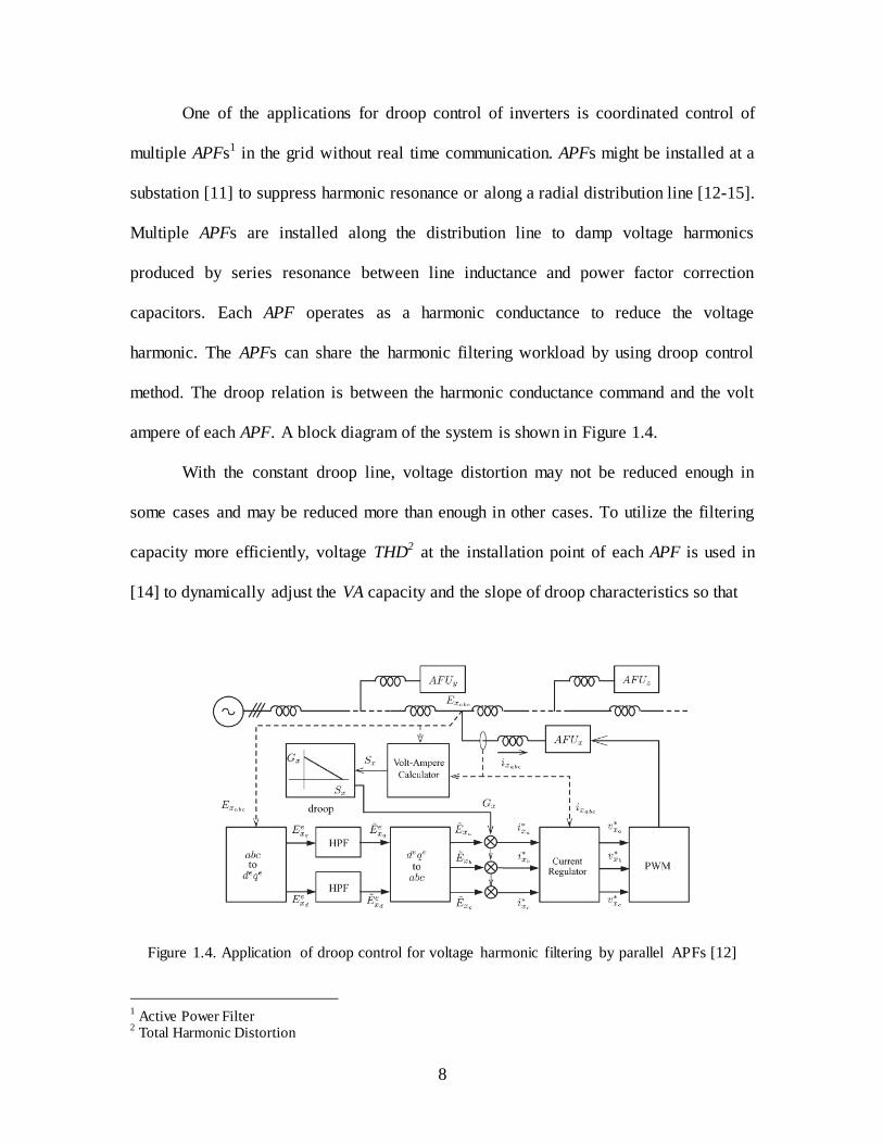
One of the applications for droop control of inverters is coordinated control of
multiple APFs1 in the grid without real time communication. APFs might be installed at a
substation [11] to suppress harmonic resonance or along a radial distribution line [12-15].
Multiple APFs are installed along the distribution line to damp voltage harmonics
produced by series resonance between line inductance and power factor correction
capacitors. Each APF operates as a harmonic conductance to reduce the voltage
harmonic. The APFs can share the harmonic filtering workload by using droop control
method. The droop relation is between the harmonic conductance command and the volt
ampere of each APF. A block diagram of the system is shown in Figure 1.4.
With the constant droop line, voltage distortion may not be reduced enough in
some cases and may be reduced more than enough in other cases. To utilize the filtering
capacity more efficiently, voltage THD2 at the installation point of each APF is used in
[14] to dynamically adjust the VA capacity and the slope of droop characteristics so that
Figure 1.4. Application of droop control for voltage harmonic filtering by parallel APFs [12]
1 Active Power Filter
2 Total Harmonic Distortion
9
the voltage THD of the installation point can always be maintained at an allowable level.
Also, in this scheme, there is one conductance for all of voltage harmonics and different
harmonics are not separated. Therefore, current harmonics can be different based on the
value of voltage harmonics. An extension of this control has been proposed in [16] and
[17] that enables control of harmonic loads separately for different orders of harmonics.
Authors in [18] introduce a cooperative imbalance compensation method using
droop control method. A droop control method based on the reactive power produced by
the negative sequence current and positive sequence line voltage is proposed. Authors
have proposed that the idea can be merged with the voltage and frequency droop controls
and be used for interface converters in the grid. Droop control of interface converters in a
microgrid is discussed in [2&4][13][19-27]. This control technique, which is emulating
the behavior of large synchronous generators in conventional grids for sharing active and
reactive power, consists of dropping frequency when delivered active power increases
and dropping voltage amplitude when delivered reactive power increases. P–f and Q–V
droop controls can be implemented as in (1-1) and (1-2). In these equations f0 and V0 are
the nominal values of frequency and voltage magnitude while Sf and Sv are droop slopes
which are determined based on ratio of active and reactive power sharing and with
consideration of frequency and voltage limits.
(1-1)
(1-2)
1.2.3 Improvement of droop control method
Authors in [22] have proposed the P-V and Q-ω boost functions to improve the
dynamic of the parallel droop controlled system as in (2-14) and (2-15).

10
dt
dPnPnEE d ..0 (1-3)
dt
dQmQmww d ..0 (1-4)
Where m and md are the proportional and derivative coefficients of reactive power Q,
respectively, and n and nd are those of active power P, respectively.
In [28] authors have proposed an adaptive droop control by using proportional,
integral and derivative term in the droop relation. Line impedance is usually an issue in
independently control of active and reactive power. This system is able to control active
and reactive power flows independently for a large range of grid impedance value. There
is a loop for grid parameters estimation in this controller. This estimation is also useful in
islanding detection.
Authors of [29] also use derivative and integrative term in droop control to
enhance the system dynamic performance both in grid-connected and islanded mode. The
method is called mode adaptive droop control. Derivative term is used when grid is
islanded while integrative term is used to control output powers of converters when it is
connected to the main grid.
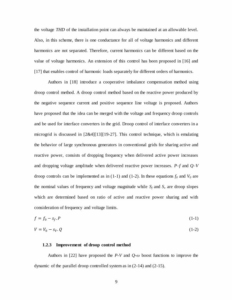
1.2.4 Higher level controllers – Hierarchical control Scheme for droop
controlled microgrids
Droop control methods alone have several drawbacks that limit their application.
One drawback is the increase of voltage magnitude deviation at load bus with load
variation. In some papers, an external control loop has been proposed to restore the
nominal values of the voltage inside the microgrid. Another disadvantage of traditional
droop control is the load dependent frequency deviation. The inverter tradeoff between

11
frequency/amplitude of voltage and active/reactive power control in islanded microgrid
cannot be avoided. Therefore the use of a low bandwidth noncritical communication
system seems inevitable. An additional control level can be used to bi-directionally
control the power flow in grid-connected microgrids and to tune voltage amplitude and
frequency. A hierarchical control structure is proposed in [4] as a general approach
toward standardization both for AC and DC microgrids. Some other authors have already
proposed secondary and tertiary controllers in which the main problem to solve is
frequency control. In this hierarchical control structure voltage stability and
synchronization issues are also considered. It is necessary to ensure that the command
and reference signals from one level to the lower levels will have low impact on the
stability and robustness performance. Thus the bandwidth must decrease with an increase
in the control level. The structure consists of three control levels beside the inner control
loop.
Level 0, inner control loops: They consist of current and voltage control loops
for a converter.
Level 1, primary control loop: This level is used to implement droop controls,
balancing energy between DGs and storage systems by improving droop relations.
Virtual output impedance, which can also be set independently for different harmonics,
are implemented in this level.
Level 2, Secondary control loop: This level is used to compensate for frequency
and amplitude deviation and also for synchronization process.
Level 3, Tertiary control loop: When microgrid is connected to the main grid,
this level is used for controlling power flow by adjusting frequency and amplitude

12
through PI controller. It can also be used to improve power quality. This level allows
multiple DGs to form a cluster and performs like a primary control for the cluster
controlling its power exchange with the rest of the network. Figure 1.5 shows a block
diagram of this hierarchical control structure.
1.2.5 Energy Management System
Real time optimization in a microgrid through frequent adjustment of power
sources output to minimize cost or meet other targets has been proposed in literatures.
Optimization may include using storage capacity to buy energy when price is low and
make use of that energy when grid connection is unavailable or price is high [30]. An
important consideration when optimizing power generation is system stability especially
when the microgrid is operated in islanded mode. In [30] authors have proposed an EMS1
as in Figure 1.6 which adjusts output power of generators in a microgrid to minimize fuel
consumption and ensures stability. It’s observed that the microgrid is less damped when
all inverters have the same droop gain than if one or more have gains below this value.
While high droop gains reduce the stability margin, low gains increase the response time
which results in poor transient behavior in terms of higher energy storage requirements to
deal with increased transient energy exchange [30].
1 Energy Management System
13
Figure 1.5. Block diagram of the hierarchical control of AC microgrid. (a) primary and secondary
control (b) tertiary control and synchronization loop [4]

14
Figure 1.6. Energy management system for microgrid [31]
1.2.6 Low level controllers for harmonics and unbalance voltage control
In order to use droop controllers for the sharing of harmonic currents or negative
sequence currents or both between converters in a microgrid, the bandwidth of lower
level controllers i.e. current and voltage controllers should be high enough to respond to
the high frequency portion of the reference voltage accurately. They also need to be
properly designed for both positive and negative sequence component performance.
There are a couple of different methods presented in the literature for design of current
and voltage controllers in situations where distortion is present. In general, they can be
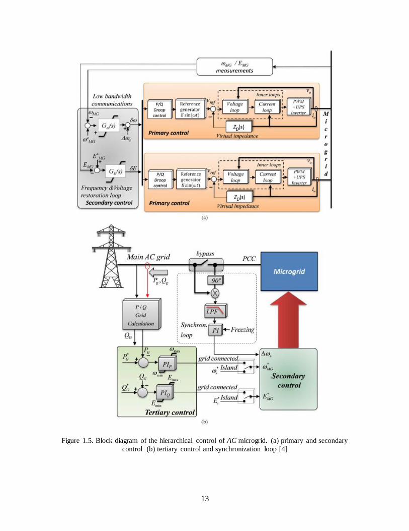
divided into synchronous frame and stationary frame controllers. Authors in [31], [32-35]
have utilized stationary frame Proportional + Resonant controllers for the control of
converters. Figure 1.7 shows the block diagram of voltage and current controllers by
using P+ Resonant controllers. For every harmonic component a P + Resonant controller
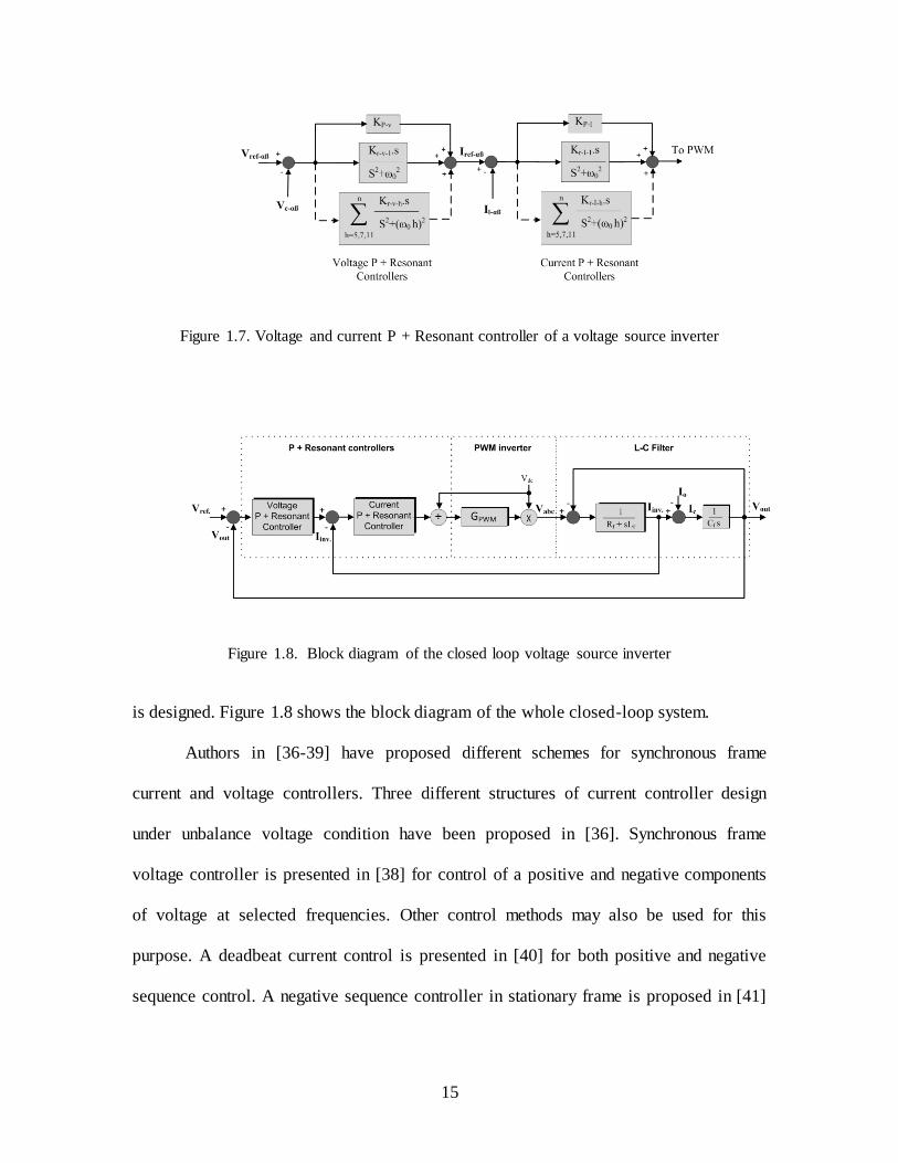
15
Figure 1.7. Voltage and current P + Resonant controller of a voltage source inverter
Figure 1.8. Block diagram of the closed loop voltage source inverter
is designed. Figure 1.8 shows the block diagram of the whole closed-loop system.
Authors in [36-39] have proposed different schemes for synchronous frame
current and voltage controllers. Three different structures of current controller design
under unbalance voltage condition have been proposed in [36]. Synchronous frame
voltage controller is presented in [38] for control of a positive and negative components
of voltage at selected frequencies. Other control methods may also be used for this
purpose. A deadbeat current control is presented in [40] for both positive and negative
sequence control. A negative sequence controller in stationary frame is proposed in [41]

16
and authors of [42] present a space vector based control for control of output voltage of
UPS in the presence of nonlinear and unbalance load.
1.3 OBJECTIVES
Power converters in an AC microgrid have unequal capabilities in generation of
different components of electrical power. Active and reactive power are generally shared
among converters with respect to their ratings but the capability of the converters may
vary based on the availability of primary power sources such as wind for wind turbines
and sunshine for photocells. Converters with no primary source can be used for
generation of reactive power and for harmonic cancellation. They can also be used for
unbalanced power generation and the converters with more energy storage capacity on
the DC bus would be able to generate more unbalanced power with smaller ripple
imposed on the DC bus. Harmonic sharing mostly depends on the structure of converter
as well as the switching frequency. Higher switching frequencies enable converters to
control higher order harmonics.
In order to be able to control all of the power components of the load among
converters in an autonomous microgrid, so that the flow of power components is
optimized within the microgrid, a comprehensive and coordinated control system is
required which enables control of each power component of the load independently from
other components. In such a system, considering the constraints for converters along with
a function for optimization of the system, sharing factors of each converter for any of the
power components can be set by a higher level control layer. The optimization function
can include target functions such as reducing fuel cost, power loss minimization, equal
loading utilization, stability and reliability increase. A control algorithm is required such

17
that by means of coordinated control of output voltage of each converter, it optimizes the
operation of the microgrid toward a targeted objective function.
Also, since in the islanded mode of operation, voltage in a microgrid may suffer
from magnitude and frequency deviation, distortion, and imbalance, the control system
should include a method to control power quality indices at the load bus.
The objective of this dissertation is to extend distributed control of active and
reactive current to ancillary functions of harmonic filtering and unbalance compensation
for comprehensive duty sharing among all converters in the microgrid according to an
optimization function. Sharing factors for each power source may need to be reset by the
management system following any change in the configuration or operation condition of
the microgrid depending on the optimization function. Low speed communication links
are required for data transfer between the management system in system-level control and
local control units. Also, due to an extra degree of freedom in the setting of output
voltage of converters for sharing of active and reactive power and ancillary functions,
power quality indices at a sensitive bus can be improved. Low speed communication
links are required for transmission of power quality indices information at load bus to
system-level control. Information from other systems is also required in Management
System in order for real-time optimization. A low speed communication link is also
needed for data transfer between other systems and the system-level control. A schematic
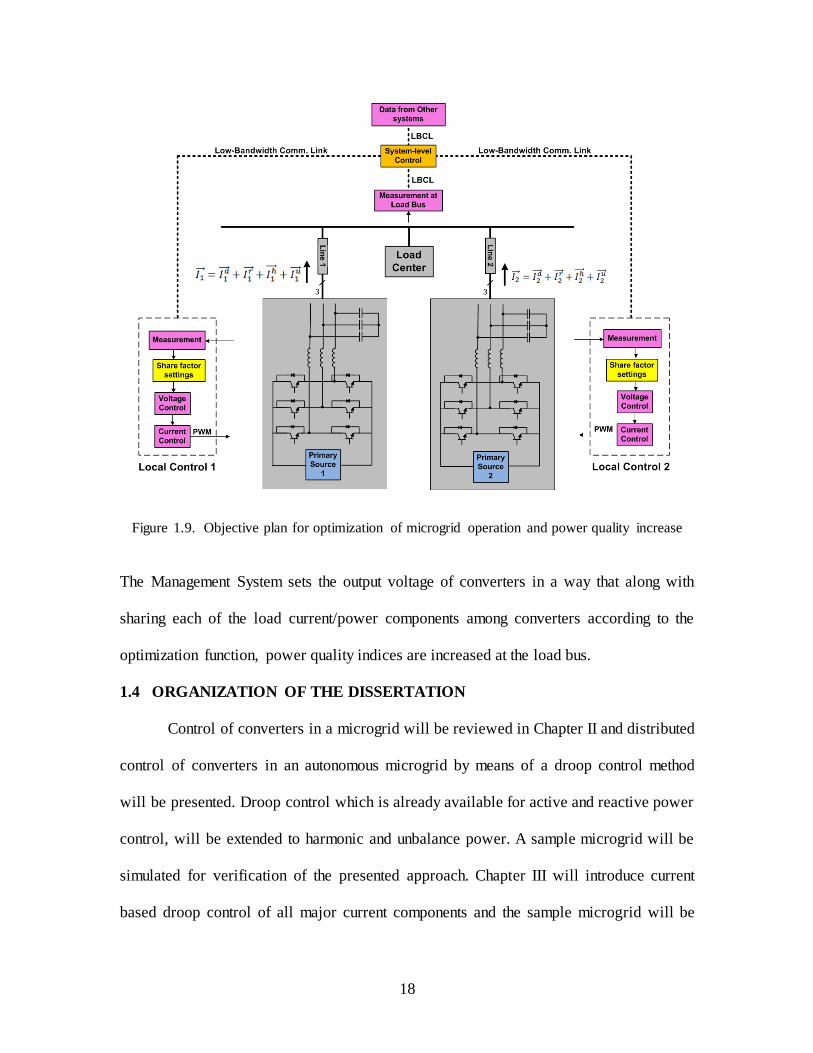
that shows the required structure for the objective of this research is shown in Figure 1.9.
In this figure output current/power of each converter includes active, reactive, harmonic
and unbalanced components. Each of these components is coordinated among all
converters.
18
Figure 1.9. Objective plan for optimization of microgrid operation and power quality increase
The Management System sets the output voltage of converters in a way that along with
sharing each of the load current/power components among converters according to the
optimization function, power quality indices are increased at the load bus.
1.4 ORGANIZATION OF THE DISSERTATION
Control of converters in a microgrid will be reviewed in Chapter II and distributed
control of converters in an autonomous microgrid by means of a droop control method
will be presented. Droop control which is already available for active and reactive power
control, will be extended to harmonic and unbalance power. A sample microgrid will be
simulated for verification of the presented approach. Chapter III will introduce current
based droop control of all major current components and the sample microgrid will be

19
simulated for verification of the current sharing method. CPC1 theory will be used for
decomposition of current into orthogonal components. A Management System and the
secondary loop control will be introduced in Chapter IV and simulations will prove that
power quality indices at load bus are well improved. The steps for controller parameters
design including low-level controllers as well as other layers of control system will be
presented in Chapter V. Chapter VI explores the optimization of a microgrid including
power units with MPPT2 system such as PV units and wind power sources and in Chapter
VII a mathematical approach for the optimization of the microgrid operation in presence
of PV and wind power units will be presented. Chapter VIII outlines key conclusions and
contributions of this work along with some ideas for continuation of the research.
1 Current Physical Components
2 Maximum Power Point Tracking
20
CHAPTER II
POWER SHARING AMONG CONVERTERS IN AN AUTONOMOUS MICROGRID
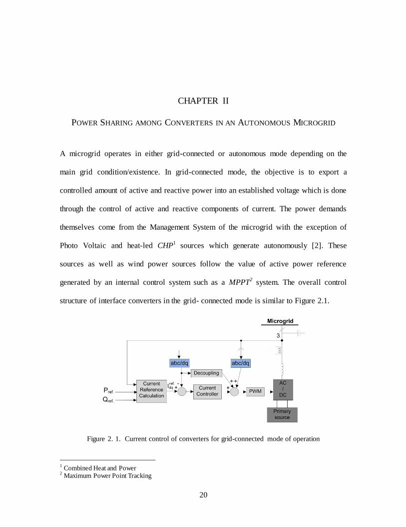
A microgrid operates in either grid-connected or autonomous mode depending on the
main grid condition/existence. In grid-connected mode, the objective is to export a
controlled amount of active and reactive power into an established voltage which is done
through the control of active and reactive components of current. The power demands
themselves come from the Management System of the microgrid with the exception of
Photo Voltaic and heat-led CHP1 sources which generate autonomously [2]. These
sources as well as wind power sources follow the value of active power reference
generated by an internal control system such as a MPPT2 system. The overall control
structure of interface converters in the grid- connected mode is similar to Figure 2.1.
Figure 2. 1. Current control of converters for grid-connected mode of operation
1 Combined Heat and Power
2 Maximum Power Point Tracking
21
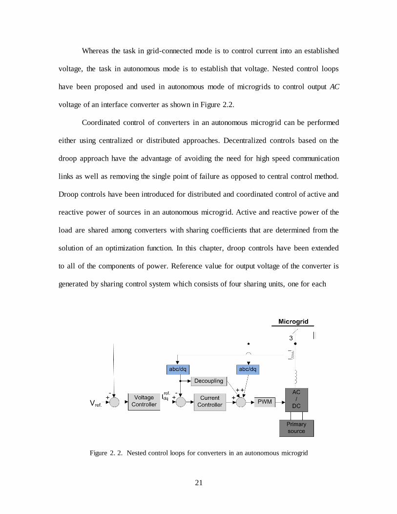
Whereas the task in grid-connected mode is to control current into an established
voltage, the task in autonomous mode is to establish that voltage. Nested control loops
have been proposed and used in autonomous mode of microgrids to control output AC
voltage of an interface converter as shown in Figure 2.2.
Coordinated control of converters in an autonomous microgrid can be performed
either using centralized or distributed approaches. Decentralized controls based on the
droop approach have the advantage of avoiding the need for high speed communication
links as well as removing the single point of failure as opposed to central control method.
Droop controls have been introduced for distributed and coordinated control of active and
reactive power of sources in an autonomous microgrid. Active and reactive power of the
load are shared among converters with sharing coefficients that are determined from the
solution of an optimization function. In this chapter, droop controls have been extended
to all of the components of power. Reference value for output voltage of the converter is
generated by sharing control system which consists of four sharing units, one for each
Figure 2. 2. Nested control loops for converters in an autonomous microgrid
22
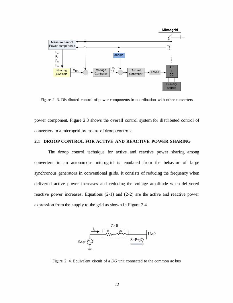
Figure 2. 3. Distributed control of power components in coordination with other converters
power component. Figure 2.3 shows the overall control system for distributed control of
converters in a microgrid by means of droop controls.
2.1 DROOP CONTROL FOR ACTIVE AND REACTIVE POWER SHARING
The droop control technique for active and reactive power sharing among
converters in an autonomous microgrid is emulated from the behavior of large
synchronous generators in conventional grids. It consists of reducing the frequency when
delivered active power increases and reducing the voltage amplitude when delivered
reactive power increases. Equations (2-1) and (2-2) are the active and reactive power
expression from the supply to the grid as shown in Figure 2.4.
Figure 2. 4. Equivalent circuit of a DG unit connected to the common ac bus

23
P=
[ (2-1)
Q=
[ (2-2)
Where z and θ are the magnitude and phase of line impedance and E and U are inverter
output voltage and common bus voltage with the phase angle difference of φ between
them. Assuming that φ is very small we obtain:
P≅
[ (2-3)
Q≅
[ (2-4)
If the line impedance phase θ is close to , which is the case for conventional power
systems, (2-3) and (2-4) will be simplified to:
P≅
(2-5)
Q≅
.( (2-6)
These show that the power angle φ affects predominantly active power P and voltage
difference affects predominantly reactive power Q. Control of frequency dynamically
controls the power angle φ and thus according to (2-5) power flow. In other words P and
Q can be adjusted independently by controlling frequency and magnitude of inverter
output voltage. Therefore (P–f) and (Q–V) droop controls can be implemented with good
precision and performance as in (2-7) and (2-8). In these equations f0 and V0 are the
nominal values of frequency and voltage magnitude while Sf and Sv are slopes of droop
characteristic lines. Figure 2.5 shows droop characteristic lines of a source for active and
reactive power sharing and Figure 2.6 demonstrates how active and reactive powers are
being shared between two sources with respect to their droop settings.

24
Figure 2. 5. frequency and voltage droop for active and reactive power control
Figure 2. 6. Sharing load power by means of droop controls. a) Active Power b) Reactive power
(2-7)
(2-8)
2.2 EFFECT OF LINE RESISTANCE
The droop method for active and reactive power control is developed based on
having a predominantly inductive line impedance. In the case of a low voltage microgrid
where θ in Figure 2-4 is not close enough to , P and Q will be coupled and using the
conventional droop control method will lead to poor performance of the system.

25
2.2.1 Modified active and reactive powers
In order to cope with the problem of coupled active and reactive powers, modified
active and reactive powers are introduced as in (2-9) to be used in droop control instead
of P and Q.
( )=(
) (
) (2-9)
Applying this transformation on (2-3) and (2-4) results in:
P ≅
(2-10)
Q ≅
( (2-11)
Therefore ( –f) and ( –V) droop controls can be utilized and and can be
controlled independently.
2.2.2 Virtual output impedance
Another method to avoid coupling of active and reactive powers is to introduce a
virtual output inductor. While effective in preventing the coupling between active and
reactive power, this approach may increase the reactive power control error due to an
increased voltage drop. A couple of methods have been introduced to improve this at the
price of more control complexity [23]. A concern with the virtual inductor
implementation is voltage drop calculation which involves differentiation of inductor
current and can cause high frequency noise amplification and in return may destabilize
the DG voltage control especially while in a transient state. Therefore, other methods
have been proposed for calculation of voltage drop, such as calculation in the αβ
reference frame. Also, in some cases where a microgrid is spatially very small, such as in
a shipboard power system, feeder impedance may be too small which decreases the
stability of droop control. Therefore, a virtual impedance is implemented in the control
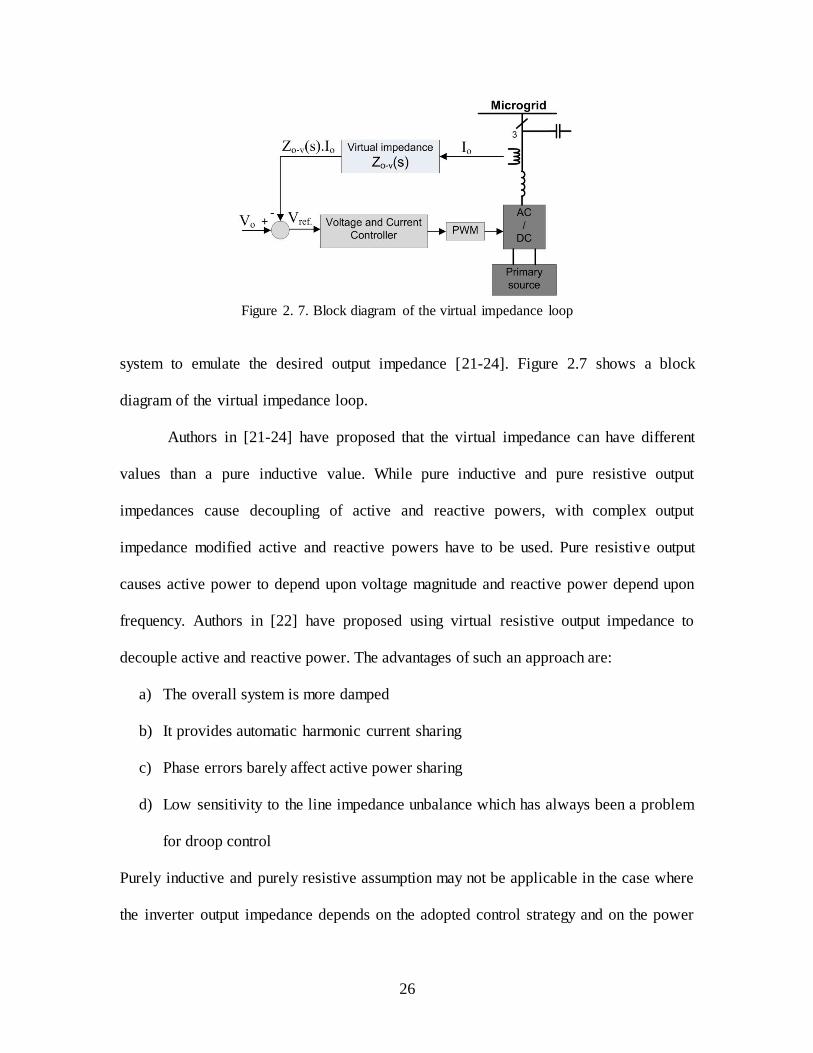
26
Figure 2. 7. Block diagram of the virtual impedance loop
system to emulate the desired output impedance [21-24]. Figure 2.7 shows a block
diagram of the virtual impedance loop.
Authors in [21-24] have proposed that the virtual impedance can have different
values than a pure inductive value. While pure inductive and pure resistive output
impedances cause decoupling of active and reactive powers, with complex output
impedance modified active and reactive powers have to be used. Pure resistive output
causes active power to depend upon voltage magnitude and reactive power depend upon
frequency. Authors in [22] have proposed using virtual resistive output impedance to
decouple active and reactive power. The advantages of such an approach are:
a) The overall system is more damped
b) It provides automatic harmonic current sharing
c) Phase errors barely affect active power sharing
d) Low sensitivity to the line impedance unbalance which has always been a problem
for droop control
Purely inductive and purely resistive assumption may not be applicable in the case where
the inverter output impedance depends on the adopted control strategy and on the power

27
stage parameters as well as line impedance. Therefore, virtual complex impedance is
proposed in [24] and [21] which offers the following advantages over virtual inductive
and resistive impedance methods [24]:
a) It can reduce the circulating current
b) Its implementation can reduce the drop of output voltage, which is caused by
virtual resistor impedance.
c) High frequency harmonic circulating current of the loads can be automatically
shared by the inverters.
d) Less sensitivity to line impedance unbalance
e) It can also be adopted to properly change the impedance angle θ to decouple active
and reactive power.
Capacitive virtual impedance is used in [43] to compensate for voltage distortion
and voltage imbalance across grid-side inductor of the LCL output filter of converter
when output current of the converter includes harmonic and unbalanced current.
Negative resistive impedance is also introduced in this dissertation and used in some of
the simulations. The magnitude of this resistance is equal to that of the resistive
impedance of the line which together cause the line impedance to appear to the converter
as a purely inductive impedance. Figure 2.8 shows the implementation of negative
resistive impedance. In the other simulations of this dissertation, a complex value of
output impedance has been implemented and modified powers have been used.
Virtual output impedance can also be used for soft start of the system when
connecting the converter to the grid or for hot swap.

28
Figure 2. 8. Negative resistive impedance implementation
2.3 INACCURACY OF REACTIVE POWER CONTROL
Another issue with droop control in microgrids is inaccuracy of reactive power
control due to line impedance. Unlike frequency which is the same in steady state over
the grid, voltage magnitude is different at load bus and supply bus. In a traditional large-
scale grid where the line is mainly inductive, inaccuracy in reactive power droop control
is caused due to the voltage drop across the line inductance because of reactive load. One
method to improve the accuracy is to exaggerate the V-Q droop effect and make the line
voltage drop negligible. However, this may cause the output voltage to be too small.
Therefore, in order for V-Q droop to control reactive power accurately, voltage drop
across the line inductance should be considered as an additional slope in the droop
characteristics of reactive power control to increase the accuracy of reactive power
control with droop as in (2-12) [23].
(2-12)
where KQi is the additional slope of converter i, Xi is the line inductance, and Ei is
29
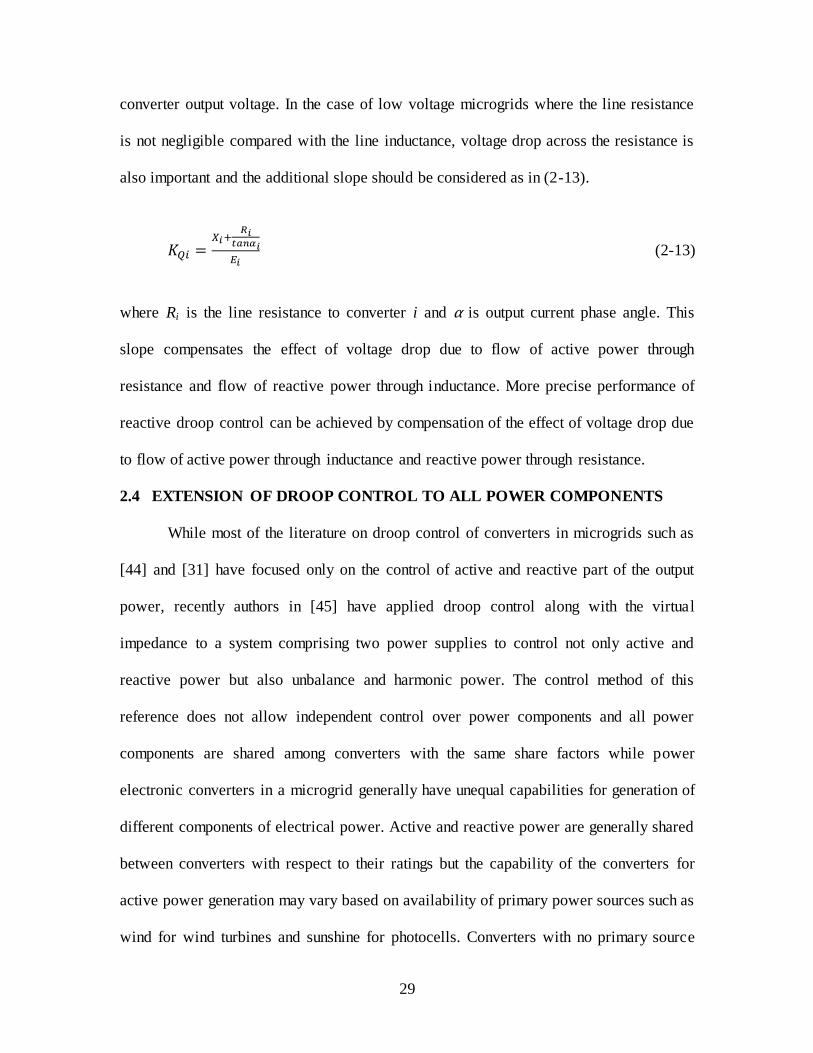
converter output voltage. In the case of low voltage microgrids where the line resistance
is not negligible compared with the line inductance, voltage drop across the resistance is
also important and the additional slope should be considered as in (2-13).
(2-13)
where Ri is the line resistance to converter i and α is output current phase angle. This
slope compensates the effect of voltage drop due to flow of active power through
resistance and flow of reactive power through inductance. More precise performance of
reactive droop control can be achieved by compensation of the effect of voltage drop due
to flow of active power through inductance and reactive power through resistance.
2.4 EXTENSION OF DROOP CONTROL TO ALL POWER COMPONENTS
While most of the literature on droop control of converters in microgrids such as
[44] and [31] have focused only on the control of active and reactive part of the output
power, recently authors in [45] have applied droop control along with the virtual
impedance to a system comprising two power supplies to control not only active and
reactive power but also unbalance and harmonic power. The control method of this
reference does not allow independent control over power components and all power
components are shared among converters with the same share factors while power
electronic converters in a microgrid generally have unequal capabilities for generation of
different components of electrical power. Active and reactive power are generally shared
between converters with respect to their ratings but the capability of the converters for
active power generation may vary based on availability of primary power sources such as
wind for wind turbines and sunshine for photocells. Converters with no primary source

30
can be used for generation of reactive power and for harmonic cancellation. They can
also be used for unbalanced power generation and the converters with larger amounts of
energy storage on the DC bus would be able to generate more unbalanced power with
smaller ripple imposed on the DC bus. Harmonic sharing mostly depends on the structure
of the converter as well as the switching frequency.
2.4.1 Extension of droop control to harmonics
An important issue in coordinated control of power supplies in a microgrid is to
supply harmonic current required by non-linear loads with proper sharing between
sources. In some islanded grids, highly nonlinear loads incorporating rectifiers may even
present the major part of the load. Supplying nonlinear loads can be incorporated either in
the frequency domain, such as by partitioning the frequency spectrum and applying
different controllers to different partitions using only a low bandwidth communication
link [2] or in the time domain such as by emulating a virtual impedance. In this
dissertation virtual impedance is used for sharing harmonic loads. Different
configurations of virtual impedance are shown in [35] which consists of pure resistive,
pure inductive, series inductive plus resistive and parallel inductive plus resistive. In this
dissertation a parallel and series configuration for output impedance is chosen so that the
fundamental component of the current passes virtually through a series complex
impedance, and each harmonic components of the current pass virtually through a
resistive impedances. Only 5th and 7th harmonics are considered here. The resistors may
have different values for different harmonics which help sharing of harmonics with
unequal ratios, but in this dissertation they have been considered to have equal values and
different orders of harmonic currents are shared among converters with same share

31
factors. In order for sharing of harmonic currents to be accurate, impedance of line from
each converter to load center should be considered in determination of virtual harmonic
resistances. Figure 2.9 shows this configuration of the virtual output impedance and the
realization of this impedance is shown in Figure 2.10.
Figure 2. 9. Implemented virtual impedance
Figure 2. 10. Realization of the virtual impedance
32
2.4.2 Extension of droop control to unbalanced power sharing
In order to share unbalance load between power sources, a method is developed
for negative sequence current sharing which is based on measurement of voltage and
current at converter output. A separate control loop is also used for sharing of the
increased amount of unbalanced current which is due to the increase of negative sequence
voltage by secondary control. Sharing of the latter part of unbalance current will be
discussed in chapter IV when secondary control performance is explained. Inner loop
controllers of the converters should be properly designed for both positive and negative
sequence component performance [40, 42]. In this dissertation, synchronous frame PI
controllers are used for both positive and negative sequence components of voltage and
current.
Negative sequence current is dependent on both positive and negative sequence
voltages, V+ and V-, when load is unbalanced. As V+ is controlled separately through
positive sequence droop controls, the right value of V- to control negative sequence
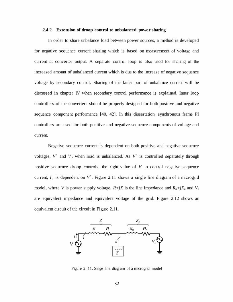
current, I-, is dependent on V+. Figure 2.11 shows a single line diagram of a microgrid
model, where V is power supply voltage, R+jX is the line impedance and Rn+jXn and Vn
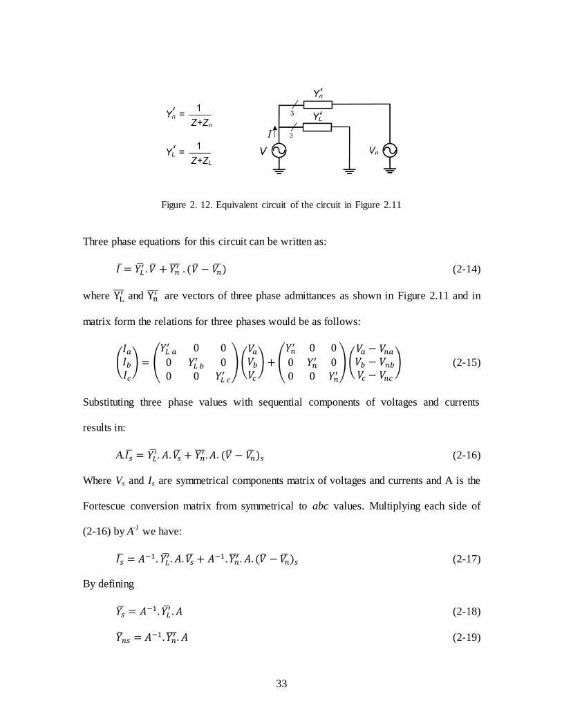
are equivalent impedance and equivalent voltage of the grid. Figure 2.12 shows an
equivalent circuit of the circuit in Figure 2.11.
Figure 2. 11. Singe line diagram of a microgrid model
33
Figure 2. 12. Equivalent circuit of the circuit in Figure 2.11
Three phase equations for this circuit can be written as:
(2-14)
where and
are vectors of three phase admittances as shown in Figure 2.11 and in
matrix form the relations for three phases would be as follows:
(
) (
)(
) (
)(
) (2-15)
Substituting three phase values with sequential components of voltages and currents
results in:
A.
(2-16)
Where Vs and Is are symmetrical components matrix of voltages and currents and A is the
Fortescue conversion matrix from symmetrical to abc values. Multiplying each side of
(2-16) by A-1 we have:
(2-17)
By defining
(2-18)
(2-19)

34
and multiplying matrices we will have:
(
)
(
) (2-20)
and for Yns,
(
) (2-21)
Considering (2-18), (2-19), (2-20) and (2-21), (2-17) can be written in in matrix
form as (2-22):
(
) (
)(
) (
)(
) (2-22)
Since there is no zero sequence voltage, negative sequence current can be calculated as:
(2-23)
V- should increase or decrease the value of I– produced by positive sequence
voltage in such a way that the required sharing condition for unbalance load is provided.
If the factor of increase or decrease is K, then V– can be calculated as:
(2-24)
So:
(2-25)
V+ is calculated by measurement of three phase voltages. Y32 and Y33 can be calculated
according to (2-20) by measuring impedance of each phase at the converter output.
can be measured at no load condition and it is constant with load variations. Now, the
35
question is how to choose the K factor. For simplicity of calculations it is assumed that
line impedances are close enough thereby load impedance from the point of different
converters is almost identical. If line impedances are extremely different, it should be
considered in calculation of K factor at each local control system. Equivalent line
impedances results in almost equal sharing of unbalanced load before applying negative
sequence voltage, V-, as positive sequence voltages are closely equal for all sources
(within a margin from the rated voltage). Before V- is applied each converter generates
1/n of the unbalance load with n being the number of connected converters in the
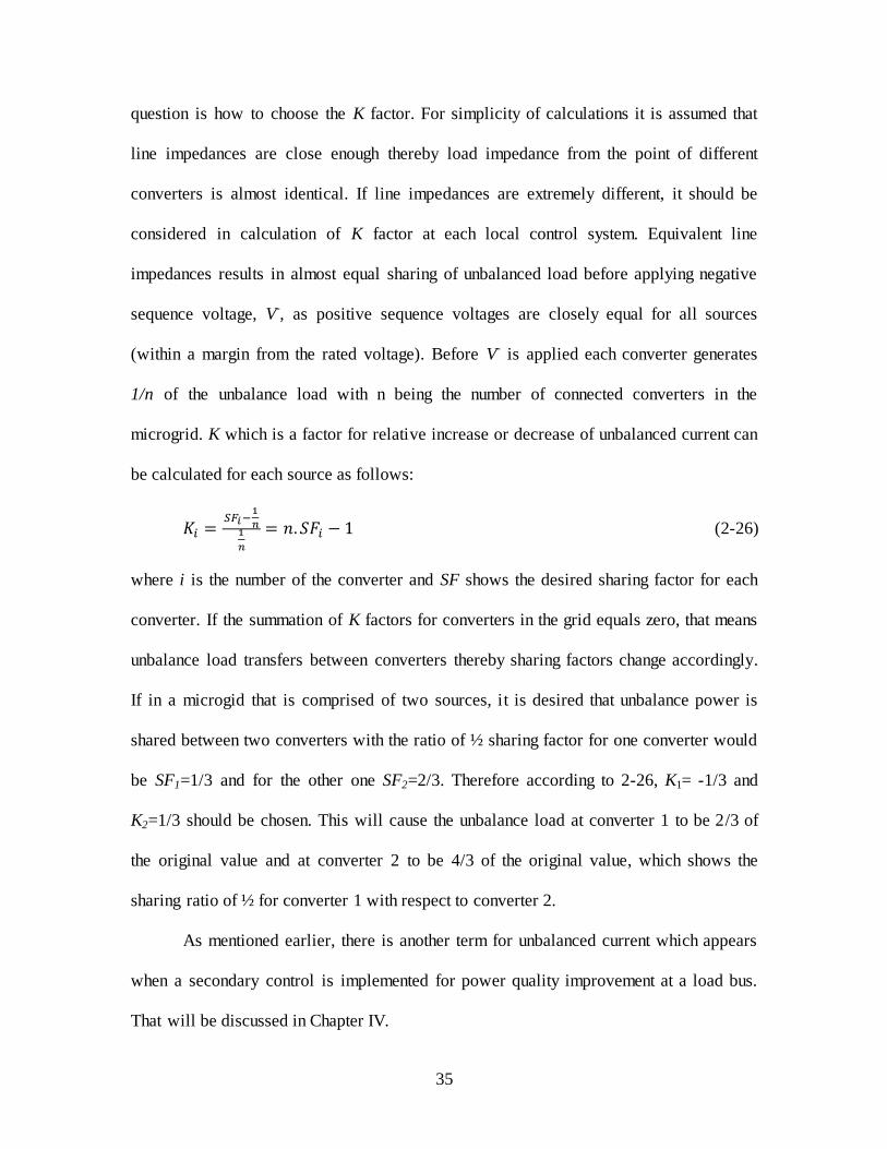
microgrid. K which is a factor for relative increase or decrease of unbalanced current can
be calculated for each source as follows:
(2-26)
where i is the number of the converter and SF shows the desired sharing factor for each
converter. If the summation of K factors for converters in the grid equals zero, that means
unbalance load transfers between converters thereby sharing factors change accordingly.
If in a microgid that is comprised of two sources, it is desired that unbalance power is
shared between two converters with the ratio of ½ sharing factor for one converter would
be SF1=1/3 and for the other one SF2=2/3. Therefore according to 2-26, K1= -1/3 and
K2=1/3 should be chosen. This will cause the unbalance load at converter 1 to be 2/3 of
the original value and at converter 2 to be 4/3 of the original value, which shows the
sharing ratio of ½ for converter 1 with respect to converter 2.
As mentioned earlier, there is another term for unbalanced current which appears
when a secondary control is implemented for power quality improvement at a load bus.
That will be discussed in Chapter IV.
36
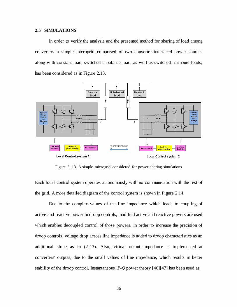
2.5 SIMULATIONS
In order to verify the analysis and the presented method for sharing of load among
converters a simple microgrid comprised of two converter-interfaced power sources
along with constant load, switched unbalance load, as well as switched harmonic loads,
has been considered as in Figure 2.13.
Figure 2. 13. A simple microgrid considered for power sharing simulations
Each local control system operates autonomously with no communication with the rest of
the grid. A more detailed diagram of the control system is shown in Figure 2.14.
Due to the complex values of the line impedance which leads to coupling of
active and reactive power in droop controls, modified active and reactive powers are used
which enables decoupled control of those powers. In order to increase the precision of
droop controls, voltage drop across line impedance is added to droop characteristics as an
additional slope as in (2-13). Also, virtual output impedance is implemented at
converters' outputs, due to the small values of line impedance, which results in better
stability of the droop control. Instantaneous P-Q power theory [46][47] has been used as

37
Figure 2. 14. Local control system of each converter
in (2-27) and (2- 28) for the calculation of output active and reactive power of each
converter. Negative sequence current which represents unbalanced current in 3-wire
systems has been calculated using Clarke transformation matrix.
(2-27)
(2-28)
Table 2-1 shows the parameters of the microgrid which is used in the simulation
along with control strategies. It is assumed that due to different converter structures as
well as switching frequencies of power supplies converter 1 is able to generate twice as
much harmonic as converter 2 does. But due to smaller capacity of supply and converters
half as much active and reactive power as converter 2 generates. Unbalanced current is
also always shared between two converters with the ratio of ½ for converter 1 with
respect to converter 2. All of the power components are controlled independently from

38
each other. Sharing factors in local controls can be re-tuned by the system operator in
order to comply with new requirements of the system or to follow another goal for
system optimization.
Table 2.1. Parameters of the simulated system
DC bus voltage: 700V Line impedance:
0.754+0.377j
AC bus rated RMS voltage (phase):
120V Virtual impedance:
0.754+0.377j
AC bus rated frequency:
60Hz Constant loads:
25kW + 25kVar
Switching frequency: 12kHz Switched Load:
Unbalanced load of 45kW + 30kVar and a Thyristor rectifier with firing angle of 30 degrees
LC filter inductance: 1mH Load
Switching times
t=1 s (switching on) and t=2 s (switching off)
LC filter capacitance: 123uF Strategy of
the sharing control:
share harmonics with the ratio of 2/1 and active,
reactive and unbalanced powers with the ratio of 1/2 between the two sources
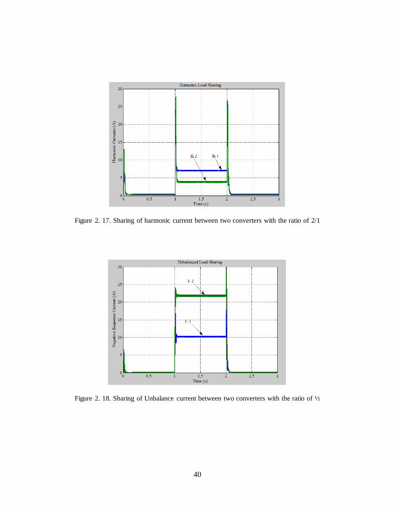
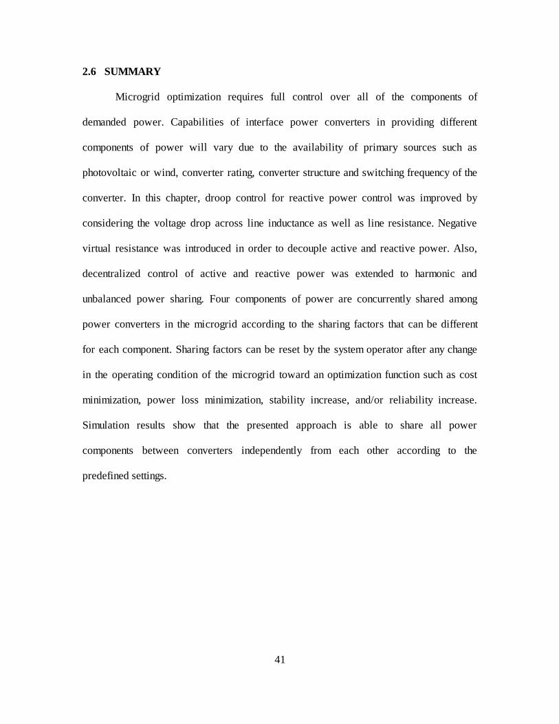
Figure 2.15, 2.16, 2.17., and 2.18 show active, reactive, harmonic and unbalance
load sharing respectively between the two sources both with and without the switched
load. There is a balanced linear load constantly connected and a load which includes
distorted current as well as unbalanced current switches ON and OFF at times 1s and 2s
respectively. It can be seen that power components are shared between the two sources
closely with the predefined share factors and with a relatively fast response time.

39
Figure 2. 15. Sharing of active current between two converters with the ratio of ½
Figure 2. 16. Sharing of reactive current between two converters with the ratio of ½
40
Figure 2. 17. Sharing of harmonic current between two converters with the ratio of 2/1
Figure 2. 18. Sharing of Unbalance current between two converters with the ratio of ½
41
2.6 SUMMARY
Microgrid optimization requires full control over all of the components of
demanded power. Capabilities of interface power converters in providing different
components of power will vary due to the availability of primary sources such as
photovoltaic or wind, converter rating, converter structure and switching frequency of the
converter. In this chapter, droop control for reactive power control was improved by
considering the voltage drop across line inductance as well as line resistance. Negative
virtual resistance was introduced in order to decouple active and reactive power. Also,
decentralized control of active and reactive power was extended to harmonic and
unbalanced power sharing. Four components of power are concurrently shared among
power converters in the microgrid according to the sharing factors that can be different
for each component. Sharing factors can be reset by the system operator after any change
in the operating condition of the microgrid toward an optimization function such as cost
minimization, power loss minimization, stability increase, and/or reliability increase.
Simulation results show that the presented approach is able to share all power
components between converters independently from each other according to the
predefined settings.
42
CHAPTER III
CURRENT-BASED DROOP CONTROL AND CPC POWER THEORY
Control of output current components of a converter in a microgrid has advantages over
control of power components. Current-based coordinated control of converters in a
microgrid has the property of short-circuit current limiting while power-based control has
an adverse impact in the presence of a short-circuit fault. Furthermore, power
components may be dependent on each other under certain conditions while according to
some power theories, current components are always orthogonal. In this chapter,
distributed control of orthogonal current components will be presented along with
simulation results for verification of the approach.
3.1 CPC1 POWER THEORY
In order for distributed control of converters in a mirogrid such that all of the
major power/current components are controlled independently, a comprehensive power
theory must be utilized. Especially in the case of autonomous microgrids where system
voltages might be asymmetrical and/or distorted, power definitions should be accurate
with independent components, to prevent degrading of the coordinated control. Several
power theories have been proposed and used in different applications, such as
Conservative Power Theory, p-q theory, and Current Physical Components theory.
Among those CPC power theory has definitions for all current components which are
1 Current Physical Components

43
independent from each other [47-49]. The CPC theory provides a physical interpretation
of power phenomena in three-phase systems under unbalanced and non-sinusoidal
conditions and the applications of this theory under non-ideal supply voltage have been
shown in [50-53].
For sinusoidal conditions, a subset of the theory decomposes the current into
active, reactive, and unbalanced components. Consider a sinusoidal and symmetrical
voltage source which is supplying a load zone as in Figure 3.1.
Figure 3. 1. Equivalent model of a load supplied by a three-phase voltage source
Voltage and current vectors are u and i as in (3-1) and (3-2).
[
√ {[ } √ { } (3-1)
[
√ {[ } √ { } (3-2)
Three-phase RMS voltage and current are defined as:
‖ ‖ √‖ ‖ ‖ ‖ ‖ ‖ (3-3)
‖ ‖ √‖ ‖ ‖ ‖ ‖ ‖ (3-4)

44
In order to perform the decomposition the load is expressed in terms of two
admittances, the equivalent admittance and unbalanced admittance. The equivalent
admittance is expressed as:
(3-5)
and the unbalance admittance is:
| | ) (3-6)
where and . Having these admittances the three-phase current
vectors can be decomposed into mutually orthogonal components as (3-7).
[ (3-7)
where ia, ir, and iu are active, reactive and unbalanced components of the current.
Equivalent admittances at the point of measurement, YRS, YST, and YTR can be calculated
by the measurement of currents and voltages at this point. Current components can be
calculated by means of equivalent and unbalance admittances as:
√ { } (3-8)
√ { } (3-9)
√ { } (3-10)
where:
(
) (3-11)
Active, reactive and unbalanced currents are at the fundamental frequency,
therefore harmonic current of the load can be calculated by subtracting them from the
total current.
(3-12)

45
If the voltage source is non-sinusoidal, a new component appears in current which
is called scattered current [49]. The amount of this component is very small as compared
with major current components and it is neglected in this dissertation.
(3-13)
When voltage is also asymmetrical, as it might be in the case in an autonomous
microgrid, a new term appears in calculation of active and reactive components of the
current as in (3-14) and (3-15) compared to symmetrical voltage case in (3-8) and (3-9)
[50].
√ { } (3-14)
√ { } (3-15)
where:
‖ ‖ (
) (3-16)
As for the unbalance current there are two counter-rotating unbalance currents each of
which is with respect to one sequence of source voltage.
(3-17)
(3-18)
where:
(3-19)
(3-20)
Up and U
n are vectors of positive and negative sequence components of source voltage
where the second and third element of these vectors are swapped in Up#
and Un# as
defined in [50]. Unbalance component of the current can be calculated by the use of these
two parts.
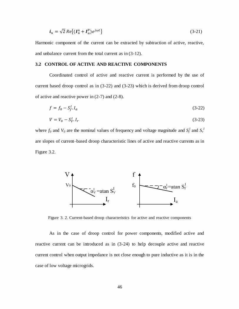
46
√ {
} (3-21)
Harmonic component of the current can be extracted by subtraction of active, reactive,
and unbalance current from the total current as in (3-12).
3.2 CONTROL OF ACTIVE AND REACTIVE COMPONENTS
Coordinated control of active and reactive current is performed by the use of
current based droop control as in (3-22) and (3-23) which is derived from droop control
of active and reactive power in (2-7) and (2-8).
(3-22)
(3-23)
where f0 and V0 are the nominal values of frequency and voltage magnitude and SfI and Sv
I
are slopes of current–based droop characteristic lines of active and reactive currents as in
Figure 3.2.
Figure 3. 2. Current-based droop characteristics for active and reactive components
As in the case of droop control for power components, modified active and
reactive current can be introduced as in (3-24) to help decouple active and reactive
current control when output impedance is not close enough to pure inductive as it is in the
case of low voltage microgrids.
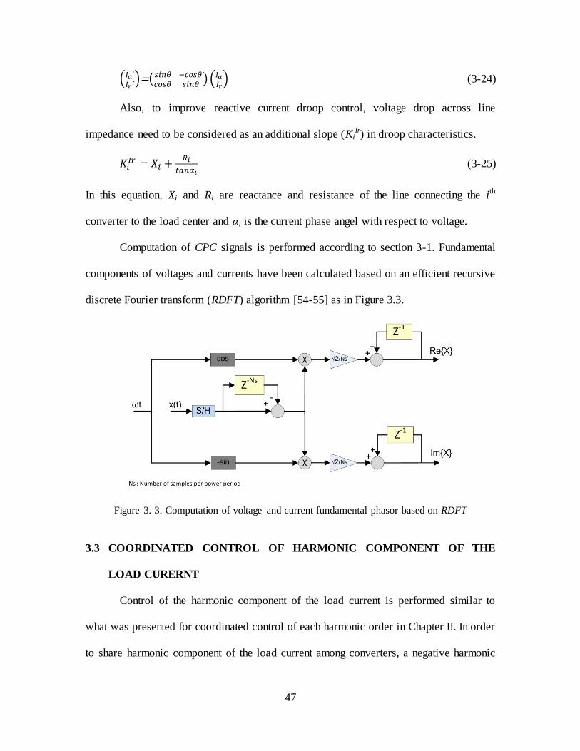
47
(
)=(
) ( ) (3-24)
Also, to improve reactive current droop control, voltage drop across line
impedance need to be considered as an additional slope (KiIr) in droop characteristics.
(3-25)
In this equation, Xi and Ri are reactance and resistance of the line connecting the ith
converter to the load center and αi is the current phase angel with respect to voltage.
Computation of CPC signals is performed according to section 3-1. Fundamental
components of voltages and currents have been calculated based on an efficient recursive
discrete Fourier transform (RDFT) algorithm [54-55] as in Figure 3.3.
Figure 3. 3. Computation of voltage and current fundamental phasor based on RDFT
3.3 COORDINATED CONTROL OF HARMONIC COMPONENT OF THE
LOAD CURERNT
Control of the harmonic component of the load current is performed similar to
what was presented for coordinated control of each harmonic order in Chapter II. In order
to share harmonic component of the load current among converters, a negative harmonic
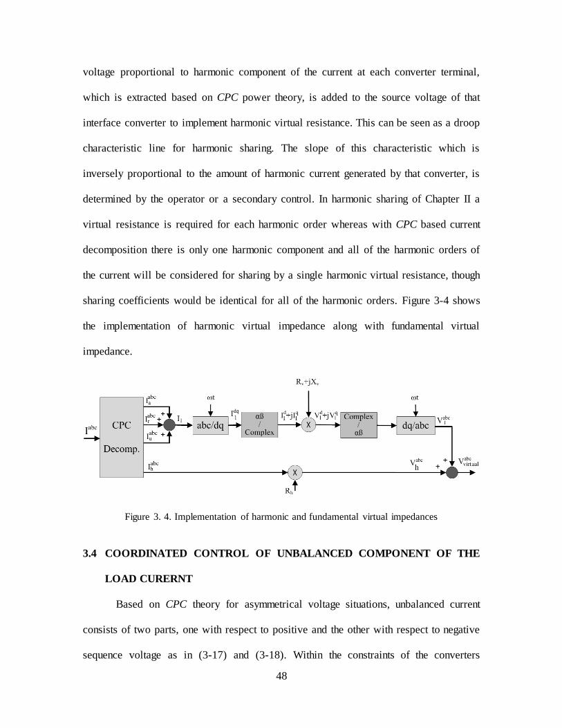
48
voltage proportional to harmonic component of the current at each converter terminal,
which is extracted based on CPC power theory, is added to the source voltage of that
interface converter to implement harmonic virtual resistance. This can be seen as a droop
characteristic line for harmonic sharing. The slope of this characteristic which is
inversely proportional to the amount of harmonic current generated by that converter, is
determined by the operator or a secondary control. In harmonic sharing of Chapter II a
virtual resistance is required for each harmonic order whereas with CPC based current
decomposition there is only one harmonic component and all of the harmonic orders of
the current will be considered for sharing by a single harmonic virtual resistance, though
sharing coefficients would be identical for all of the harmonic orders. Figure 3-4 shows
the implementation of harmonic virtual impedance along with fundamental virtual
impedance.
Figure 3. 4. Implementation of harmonic and fundamental virtual impedances
3.4 COORDINATED CONTROL OF UNBALANCED COMPONENT OF THE
LOAD CURERNT
Based on CPC theory for asymmetrical voltage situations, unbalanced current
consists of two parts, one with respect to positive and the other with respect to negative
sequence voltage as in (3-17) and (3-18). Within the constraints of the converters

49
parameters, it is necessary to determine which part of unbalanced current is important to
control. The goal might even be a minimization of both with specific weighting
coefficients. Since in a microgrid the main component of the voltage is the positive
sequence, unbalance current with respect to positive sequence voltage is considered to be
shared among converters in this dissertation. A method is developed which is based on
setting the negative sequence voltage to compensate a part of the negative sequence
current produced by positive sequence voltage due to unbalance loading. The amount of
this part depends on the share of converter for unbalanced current generation. If a
secondary control exists, as will be explained in Chapter IV, there would be an extra part
in unbalanced current. In Chapter IV it will be shown that another controller is also used
in such a case for sharing of the increased amount of unbalanced current due to the
increase of negative sequence voltage by the secondary control.
As mentioned above, unbalanced current of an asymmetrically supplied load in
terms of CPC power theory has two counter-rotating parts. One is with respect to positive
sequence voltage and the other with respect to negative sequence voltage. The former
current is negative sequence and the later one is positive sequence current.
(
)= (
) (3-26)
(
)= (
) (3-27)
where is the vector of three-phase negative sequence unbalance current and
is the
vector of three-phase positive sequence unbalance current. and are phasors of
phase R for positive and negative sequence of the supply voltage. Here, the calculation is

50
formed to share the negative sequence part of the unbalance current as in (3-26), but it
can be extended to a combination of the two parts. Equation (3-26) for the phase R of the
current yields
(3-28)
The first term of unbalance current in (3-28) is due to load imbalance and exists even
with balanced voltage. The second term appears in the presence of negative sequence
voltage on the unbalance load.
In the following, is the part of negative sequence voltage which is applied in
the local control and does not include the part that may be added by the secondary
control. In order for to be able to control it is easier if the two parts in (3-28) be
kept in the same phase. Therefore:
(3-29)
where K is a real value that controls the negative sequence current. Substituting the
values of and in (3-29) and converting the phase voltages to symmetrical
components yields a vector equation as in (3-30) for the calculation of the magnitude and
phase of .
| | √ =C ( | | | | (3-30)
| | and | | are the magnitude of negative and positive sequence voltage and is the
angle of with respect to . Also in this equation:
(3-31)
(3-32)
(3-33)
In order for this equation to have a solution there are two conditions as below:

51
√ { } R { } √ R { } { } (3-34)
(3-35)
where:
{ } (3-36)
√ { } (3-37)
{ } √ { } (3-38)
{ } (3-39)
The last two conditions may not always be true, but in the calculation of phase
impedances i.e. , , and there is an extra degree of freedom which gives
infinite set of impedances all of which bring about the same line current. Therefore, the
impedance values are checked and a set of impedances which satisfies the above
conditions is picked. Change of K in (3-29) leads to change of negative sequence voltage
applied which in turn changes the negative sequence unbalance current in (3-28). The
amount of the first term in unbalance current, , is known for converters with the
knowledge of line impedances. K factors can be set to increase or decrease unbalance
current to reach to a desired sharing of unbalance current among converters.
3.5 SIMULATIONS
This control method for current-based sharing of load components based on CPC
power theory was applied in a simulation to a microgrid comprised of two converter
interfaced power sources which are connecting to a load center through lines impedances.
The load center includes a constant balanced load, a switched balanced and a switched
unbalance load, as well as a switched harmonic load. Figure 3.5 shows the block diagram
of the simulated microgrid and Figure 3.6 shows the control system implemented on each
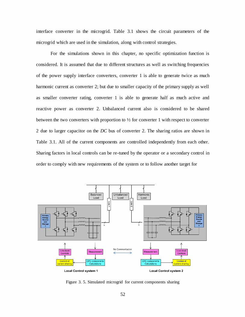
52
interface converter in the microgrid. Table 3.1 shows the circuit parameters of the
microgrid which are used in the simulation, along with control strategies.
For the simulations shown in this chapter, no specific optimization function is
considered. It is assumed that due to different structures as well as switching frequencies
of the power supply interface converters, converter 1 is able to generate twice as much
harmonic current as converter 2; but due to smaller capacity of the primary supply as well
as smaller converter rating, converter 1 is able to generate half as much active and
reactive power as converter 2. Unbalanced current also is considered to be shared
between the two converters with proportion to ½ for converter 1 with respect to converter
2 due to larger capacitor on the DC bus of converter 2. The sharing ratios are shown in
Table 3.1. All of the current components are controlled independently from each other.
Sharing factors in local controls can be re-tuned by the operator or a secondary control in
order to comply with new requirements of the system or to follow another target for
Figure 3. 5. Simulated microgrid for current components sharing
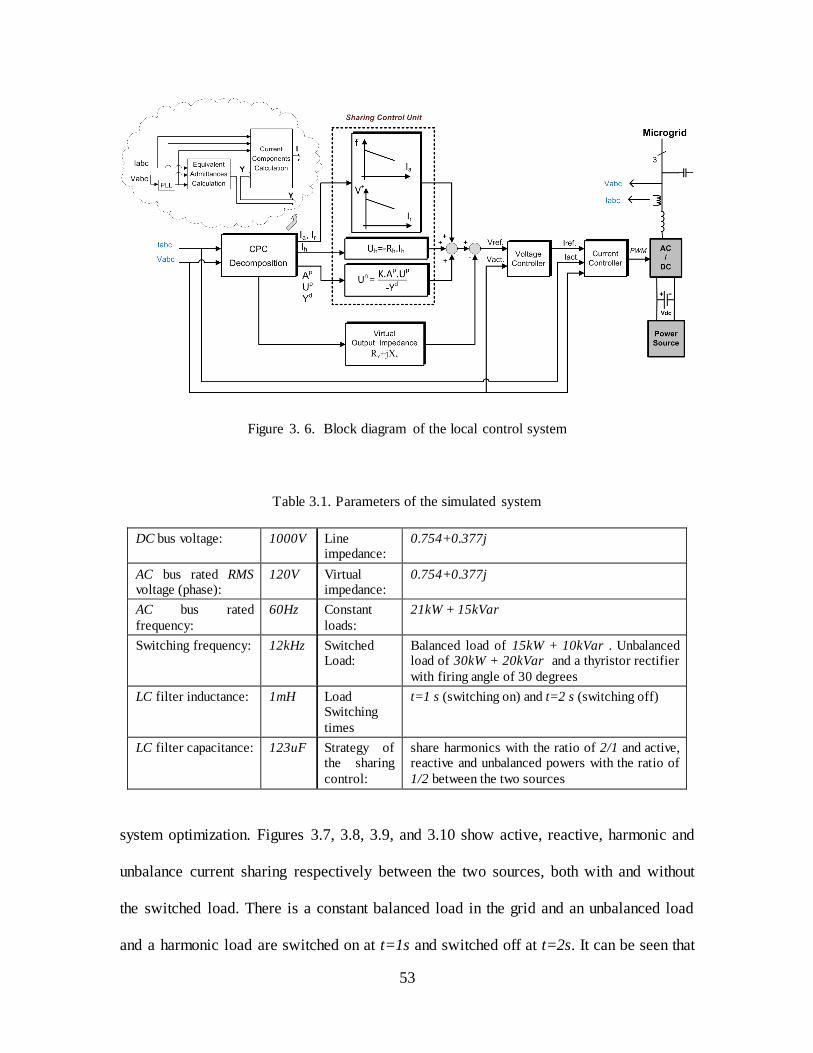
53
Figure 3. 6. Block diagram of the local control system
Table 3.1. Parameters of the simulated system
DC bus voltage: 1000V Line impedance:
0.754+0.377j
AC bus rated RMS voltage (phase):
120V Virtual impedance:
0.754+0.377j
AC bus rated
frequency:
60Hz Constant
loads:
21kW + 15kVar
Switching frequency: 12kHz
Switched Load:
Balanced load of 15kW + 10kVar . Unbalanced load of 30kW + 20kVar and a thyristor rectifier
with firing angle of 30 degrees
LC filter inductance: 1mH Load Switching
times
t=1 s (switching on) and t=2 s (switching off)
LC filter capacitance: 123uF Strategy of the sharing
control:
share harmonics with the ratio of 2/1 and active, reactive and unbalanced powers with the ratio of
1/2 between the two sources
system optimization. Figures 3.7, 3.8, 3.9, and 3.10 show active, reactive, harmonic and
unbalance current sharing respectively between the two sources, both with and without
the switched load. There is a constant balanced load in the grid and an unbalanced load
and a harmonic load are switched on at t=1s and switched off at t=2s. It can be seen that
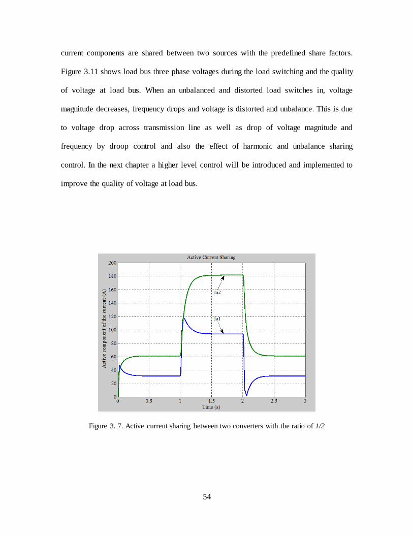
54
current components are shared between two sources with the predefined share factors.
Figure 3.11 shows load bus three phase voltages during the load switching and the quality
of voltage at load bus. When an unbalanced and distorted load switches in, voltage
magnitude decreases, frequency drops and voltage is distorted and unbalance. This is due
to voltage drop across transmission line as well as drop of voltage magnitude and
frequency by droop control and also the effect of harmonic and unbalance sharing
control. In the next chapter a higher level control will be introduced and implemented to
improve the quality of voltage at load bus.
Figure 3. 7. Active current sharing between two converters with the ratio of 1/2

55
Figure 3. 8. Reactive current sharing between two converters with the ratio of ½
Figure 3. 9. Harmonic current sharing between two converters with the ratio of 2/1

56
Figure 3. 10. Unbalance current sharing between two converters with the ratio of 1/2
Figure 3. 11. Three phase voltages at load bus at the time of load switching

57
3.6 SUMMARY
Coordinated control of current components among converters in an autonomous
microgrid was presented in this chapter. Current-based control of load sharing has
advantages over power-based control including fault current limiting as well as
independence of current components under CPC power theory. This theory has been used
for decomposition of current into orthogonal components. CPC power theory for systems
with distorted and asymmetrical supply was briefly introduced and equations for active
and reactive current sharing was presented along with improvement of reactive power
control by considering voltage drop across line as an extra slope for droop line
characteristics. Based on CPC power theory, unbalanced current under asymmetrical
voltage has two counter-rotating components each of which is with respect to one
sequence of the voltage. As the major part of the voltage is positive sequence voltage, the
unbalance current component with respect to positive sequence of voltage was considered
for sharing among converters. A simulation verifies this method of coordinated control of
current components. Since the load is unbalanced and distorted, due to voltage drop
across line as well as the effect of current components sharing on the source voltage, the
load bus voltage is unbalance and distorted which shows the requirement for power
quality increase at load bus. This is performed through development of a higher level
control in the next chapter with simulations for verification.

58
CHAPTER IV
POWER QUALITY IMPROVEMENT BY SECONDARY CONTROL LOOP
Distributed control of converters in an autonomous microgrid enables sharing of load
components among converters with no need for high-bandwidth communication link as
well as any single point of failure. In return, it impacts the quality of voltage throughout
the microgrid. Droop control methods for active and reactive power control consists of
recuding frequency and magnitude of voltage as output active and reactive power of the
converter increases which causes the magnitude and frequency of load bus voltage
deviate from their rated values. Furthermore, there is a voltage drop across the lines
connecting sources to the load bus which increases voltage magnitude deviation on the
load bus. Distributed control of harmonics and unbalanced current of the converters,
which was explained in Chapters II and III, increases THD and unbalance component of
the voltage at load buses in a similar way. In order to improve the quality of voltage at
sensitive load buses, a secondary control is introduced in this chapter. This control layer
has lower bandwidth compared with local controls and utilizes LBCL1 to transmit data
between local controls and secondary control. Secondary control collects data of voltage
quality at sensitive loads bus and dispatches DC signals to local control systems in order
to correct the reference value for output voltage in such a way that voltage quality at load
bus is improved while sharing coefficients are not influenced. This control layer can also
1 Low Bandwidth Communication Link
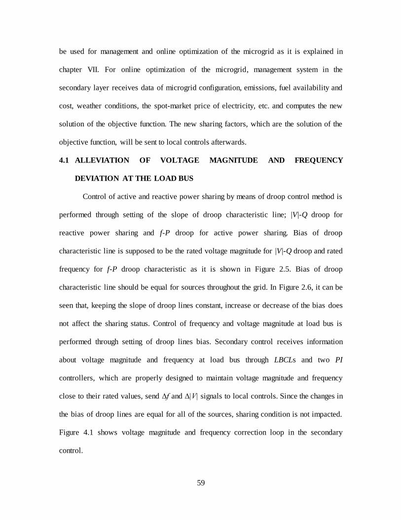
59
be used for management and online optimization of the microgrid as it is explained in
chapter VII. For online optimization of the microgrid, management system in the
secondary layer receives data of microgrid configuration, emissions, fuel availability and
cost, weather conditions, the spot-market price of electricity, etc. and computes the new
solution of the objective function. The new sharing factors, which are the solution of the
objective function, will be sent to local controls afterwards.
4.1 ALLEVIATION OF VOLTAGE MAGNITUDE AND FREQUENCY
DEVIATION AT THE LOAD BUS
Control of active and reactive power sharing by means of droop control method is
performed through setting of the slope of droop characteristic line; |V|-Q droop for
reactive power sharing and f-P droop for active power sharing. Bias of droop
characteristic line is supposed to be the rated voltage magnitude for |V|-Q droop and rated
frequency for f-P droop characteristic as it is shown in Figure 2.5. Bias of droop
characteristic line should be equal for sources throughout the grid. In Figure 2.6, it can be
seen that, keeping the slope of droop lines constant, increase or decrease of the bias does
not affect the sharing status. Control of frequency and voltage magnitude at load bus is
performed through setting of droop lines bias. Secondary control receives information
about voltage magnitude and frequency at load bus through LBCLs and two PI
controllers, which are properly designed to maintain voltage magnitude and frequency
close to their rated values, send ∆f and ∆|V| signals to local controls. Since the changes in
the bias of droop lines are equal for all of the sources, sharing condition is not impacted.
Figure 4.1 shows voltage magnitude and frequency correction loop in the secondary
control.
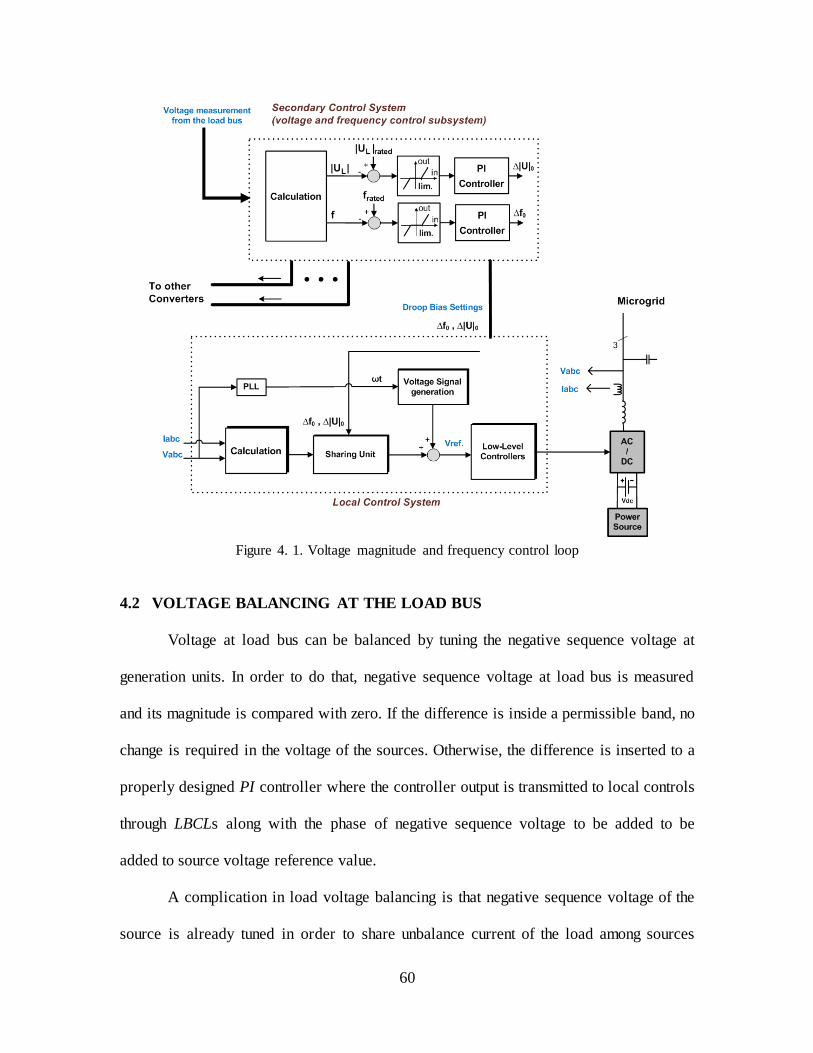
60
Figure 4. 1. Voltage magnitude and frequency control loop
4.2 VOLTAGE BALANCING AT THE LOAD BUS
Voltage at load bus can be balanced by tuning the negative sequence voltage at
generation units. In order to do that, negative sequence voltage at load bus is measured
and its magnitude is compared with zero. If the difference is inside a permissible band, no
change is required in the voltage of the sources. Otherwise, the difference is inserted to a
properly designed PI controller where the controller output is transmitted to local controls
through LBCLs along with the phase of negative sequence voltage to be added to be
added to source voltage reference value.
A complication in load voltage balancing is that negative sequence voltage of the
source is already tuned in order to share unbalance current of the load among sources
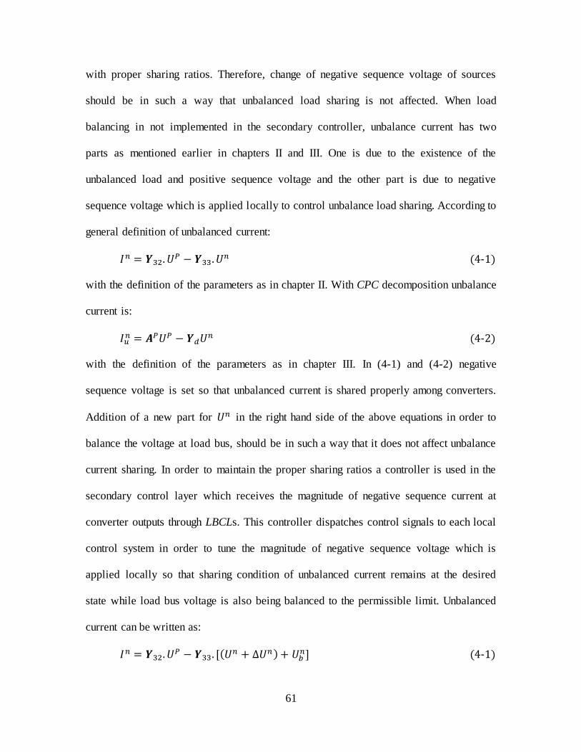
61
with proper sharing ratios. Therefore, change of negative sequence voltage of sources
should be in such a way that unbalanced load sharing is not affected. When load
balancing in not implemented in the secondary controller, unbalance current has two
parts as mentioned earlier in chapters II and III. One is due to the existence of the
unbalanced load and positive sequence voltage and the other part is due to negative
sequence voltage which is applied locally to control unbalance load sharing. According to
general definition of unbalanced current:
(4-1)
with the definition of the parameters as in chapter II. With CPC decomposition unbalance
current is:
(4-2)
with the definition of the parameters as in chapter III. In (4-1) and (4-2) negative
sequence voltage is set so that unbalanced current is shared properly among converters.
Addition of a new part for in the right hand side of the above equations in order to
balance the voltage at load bus, should be in such a way that it does not affect unbalance
current sharing. In order to maintain the proper sharing ratios a controller is used in the
secondary control layer which receives the magnitude of negative sequence current at
converter outputs through LBCLs. This controller dispatches control signals to each local
control system in order to tune the magnitude of negative sequence voltage which is
applied locally so that sharing condition of unbalanced current remains at the desired
state while load bus voltage is also being balanced to the permissible limit. Unbalanced
current can be written as:
[
(4-1)

62
In the above equation, is the negative sequence voltage which is computed and applied
locally to share unbalanced current when load voltage balancing controller does not exist.
is the output of the voltage balancing controller which is added to source voltage in
order to balance voltage at load bus. Phase of this voltage is in accordance with the phase
of negative sequence voltage at load bus. is a voltage, in phase with and is added
to correct the sharing ratios after addition of to source voltage. Load bus voltage
balancing control loop of the secondary control layer is shown in Figure 4.2
4.3 REDUCTION OF VOLTAGE DISTORTION AT THE LOAD BUS
When load is nonlinear voltage drop across line impedance leads to distortion on
the voltage at load bus. Also harmonic sharing control which adds a distorted voltage to
voltage reference value in local control causes the increase of distortion on load bus
voltage. Harmonic components of the load bus voltage can be minimized by tuning the
output voltage of the generation units. In the secondary control layer, each main
harmonic component of the load bus voltage is calculated, compared with zero and
inserted to a properly designed PI controller which generates the signal for the
appropriate voltage of that harmonic order which needs to be added to the source voltage.
One controller is required for each harmonic order. The number of considered harmonics
depends on THD reduction requirements at load bus as well as load current
characteristics. The voltage signal which is generated by each controller is transmitted to
local control through LBCL to be added to voltage reference. It should be noted that
change of harmonic currents of the load due to the addition of harmonics to source
voltages is very small and negligible. Also, since the harmonic voltages that are added to
different sources are identical it does not generate a flow of harmonic currents between
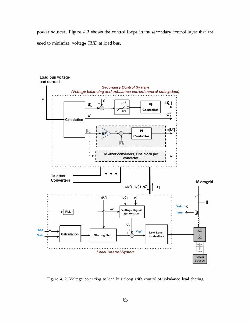
63
power sources. Figure 4.3 shows the control loops in the secondary control layer that are
used to minimize voltage THD at load bus.
Figure 4. 2. Voltage balancing at load bus along with control of unbalance load sharing
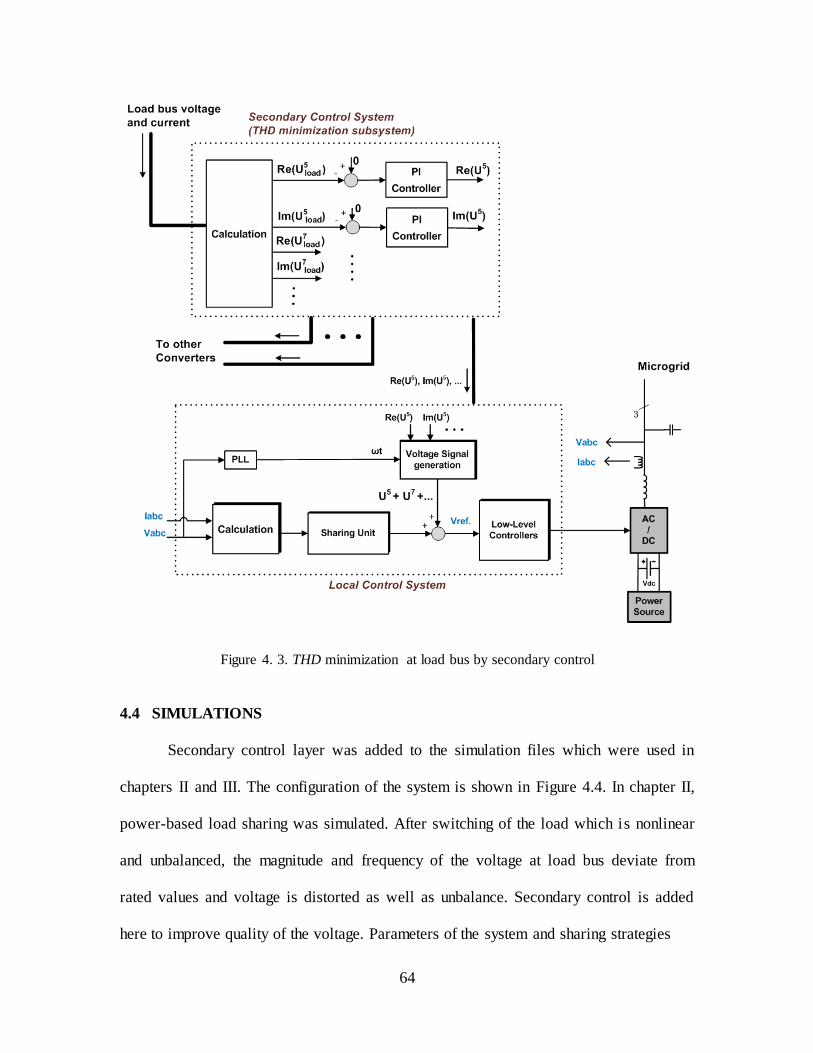
64
Figure 4. 3. THD minimization at load bus by secondary control
4.4 SIMULATIONS
Secondary control layer was added to the simulation files which were used in
chapters II and III. The configuration of the system is shown in Figure 4.4. In chapter II,
power-based load sharing was simulated. After switching of the load which is nonlinear
and unbalanced, the magnitude and frequency of the voltage at load bus deviate from
rated values and voltage is distorted as well as unbalance. Secondary control is added
here to improve quality of the voltage. Parameters of the system and sharing strategies
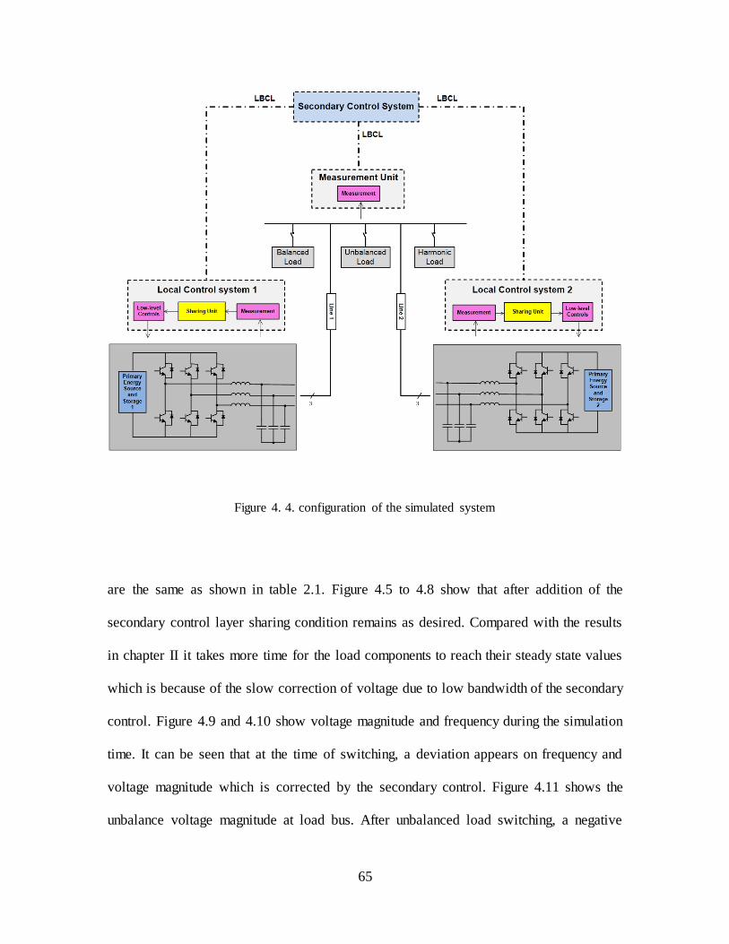
65
Figure 4. 4. configuration of the simulated system
are the same as shown in table 2.1. Figure 4.5 to 4.8 show that after addition of the
secondary control layer sharing condition remains as desired. Compared with the results
in chapter II it takes more time for the load components to reach their steady state values
which is because of the slow correction of voltage due to low bandwidth of the secondary
control. Figure 4.9 and 4.10 show voltage magnitude and frequency during the simulation
time. It can be seen that at the time of switching, a deviation appears on frequency and
voltage magnitude which is corrected by the secondary control. Figure 4.11 shows the
unbalance voltage magnitude at load bus. After unbalanced load switching, a negative

66
sequence voltage appears at load bus which is removed by the secondary control
afterwards. THD of the load bus voltage is measured both before and after the secondary
control implementation and shown in Figure 4.12 and 4.13 which indicate the
improvement of THD by the secondary control. Figure 4.14 shows three phase voltages
during and right after load switching that confirms power quality increase at load bus.
Figure 4. 5. Sharing of active power between the two converters with ratio of 1/2
Figure 4. 6. Sharing of reactive power between the two converters with ratio of 1/2

67
Figure 4. 7. Sharing of harmonic current between the two converters with ratio of 2/1
Figure 4. 8. Sharing of unbalanced current between the two converters with ratio of ½
Figure 4. 9. Reinstatement of voltage magnitude at Load bus by the secondary control
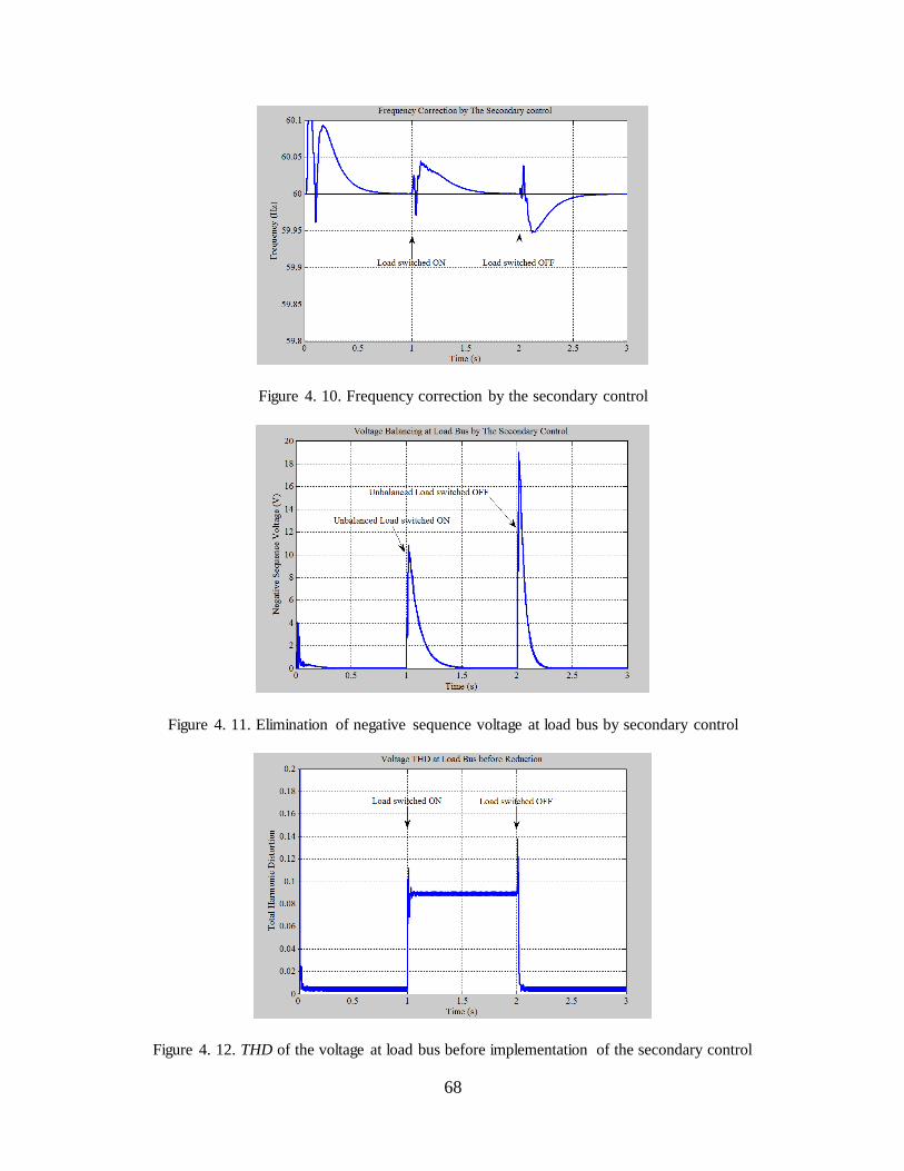
68
Figure 4. 10. Frequency correction by the secondary control
Figure 4. 11. Elimination of negative sequence voltage at load bus by secondary control
Figure 4. 12. THD of the voltage at load bus before implementation of the secondary control
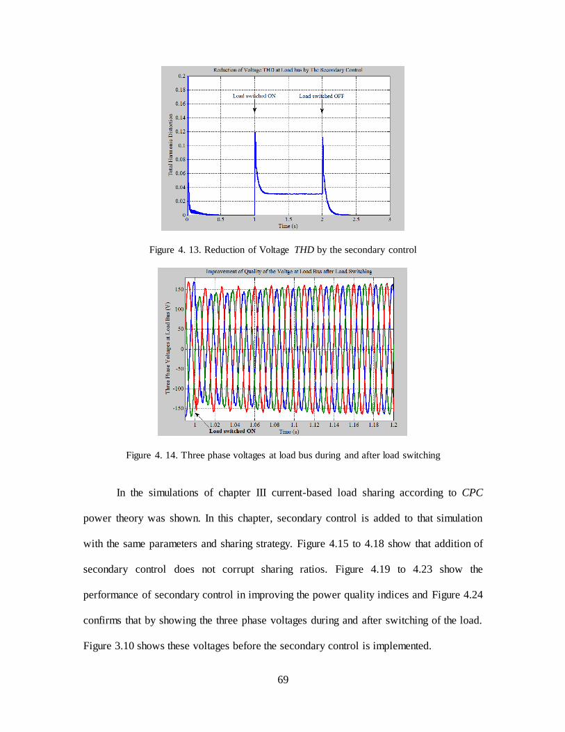
69
Figure 4. 13. Reduction of Voltage THD by the secondary control
Figure 4. 14. Three phase voltages at load bus during and after load switching
In the simulations of chapter III current-based load sharing according to CPC
power theory was shown. In this chapter, secondary control is added to that simulation
with the same parameters and sharing strategy. Figure 4.15 to 4.18 show that addition of
secondary control does not corrupt sharing ratios. Figure 4.19 to 4.23 show the
performance of secondary control in improving the power quality indices and Figure 4.24
confirms that by showing the three phase voltages during and after switching of the load.
Figure 3.10 shows these voltages before the secondary control is implemented.

70
Figure 4. 15. Sharing of active current between the two converters with ratio of 1/2
Figure 4. 16. Sharing of reactive current between the two converters with ratio of 1/2
Figure 4. 17. Sharing of harmonic current between the two converters with ratio of 2/1

71
Figure 4. 18. Sharing of unbalanced current between the two converters with ratio of 1/2
Figure 4. 19. Reinstatement of voltage magnitude at load bus by secondary control
Figure 4. 20. Correction of frequency at load bus by secondary control
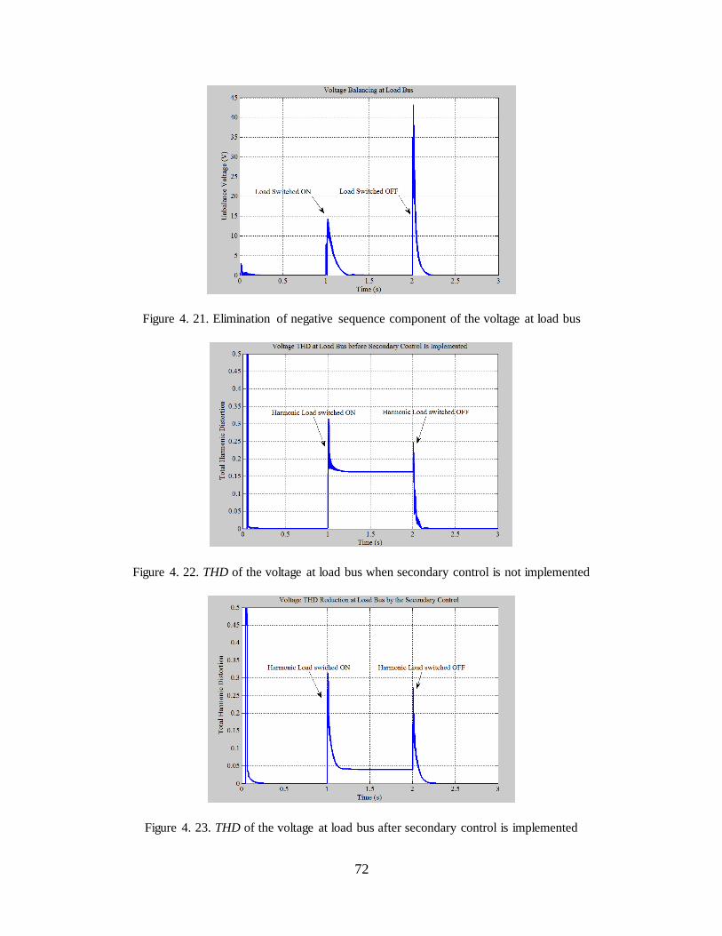
72
Figure 4. 21. Elimination of negative sequence component of the voltage at load bus
Figure 4. 22. THD of the voltage at load bus when secondary control is not implemented
Figure 4. 23. THD of the voltage at load bus after secondary control is implemented

73
Figure 4. 24. Improvement of quality indices of the voltage at load bus - three phase voltages
4.5 SUMMARY
Switching of loads in an autonomous microgrid has an adverse impact on the
quality of voltage. While load switching generally affects the magnitude of voltage at the
load bus, nonlinear and unbalanced loads cause distortion and imbalance on the load
voltage. The effect is increased by the performance of the load sharing units in local
control systems. The load sharing unit also impacts the frequency of the system after each
load switching. As local controls are operating in accordance with each other they cannot
individually act toward voltage quality increase or the sharing condition will be
disrupted. In order to improve the quality of voltage at load bus a secondary control layer
was designed in this chapter which receives power quality indices of the load bus and
applies correction signals to each local control system so that along with load voltage
improvement, sharing conditions remain as desired. Control loops for improvement of
each voltage index i.e. voltage magnitude, frequency, imbalance and distortion were
presented. Simulation results verify the performance of secondary control in increasing
power quality and confirm that desired sharing conditions are maintained.

74
CHAPTER V
DESIGN OF THE CONTROL PARAMETERS AND STABILITY ANALYSIS
In this chapter, the controller structure and parameters of the local control system as well
as secondary control will be designed and analyzed from the viewpoint of stability issues
for the range of variables. It is shown that control system is stable with reasonable
stability margins.
5.1 CURRENT CONTROL LOOP
This loop is the most inner control loop and should have the highest bandwidth among all
control loops. This is important considering the high bandwidth of voltage reference
when converters are being controlled in coordinated with each other to supply a harmonic
and unbalanced load. This controller can be of any type such as PID controller, adaptive
deadbeat controller, P + Resonance controller, etc. For a converter supplying a load in an
autonomous operation such as in Figure 5.1 a deadbeat current controller is designed and
compared with a PI controller. The parameters of the grid are shown in table 1
considering that output AC voltage is not controlled in this step and only output current is
being controlled. Figure 5.2 represents the response of these two controllers to a distorted
current reference, shown with dots. Although deadbeat current controller causes a delay
of two modulation period due to the nonzero computational time of the microprocessor
and the conversion time of A/D converters, it shows a better dynamic response [56].
Therefore, Current controller is chosen to be a deadbeat controller.
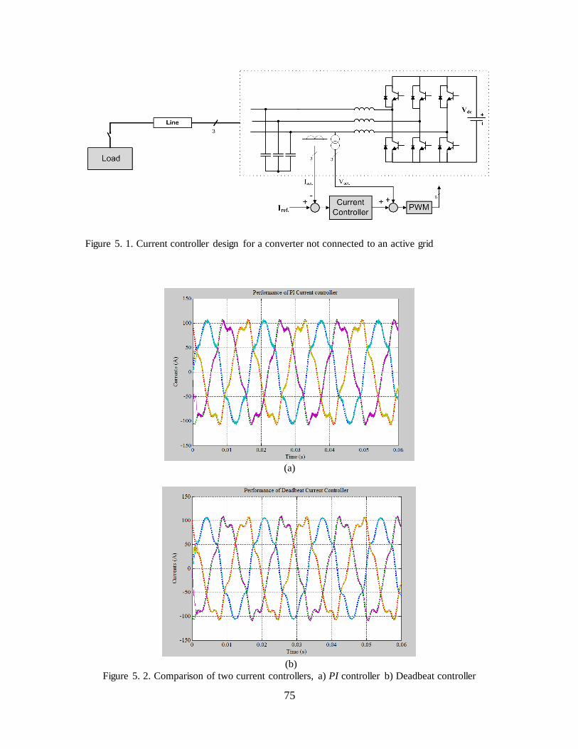
75
Figure 5. 1. Current controller design for a converter not connected to an active grid
(a)
(b)
Figure 5. 2. Comparison of two current controllers, a) PI controller b) Deadbeat controller
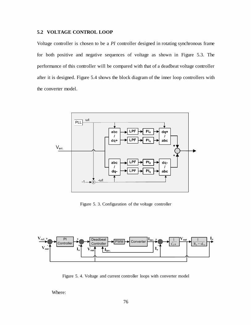
76
5.2 VOLTAGE CONTROL LOOP
Voltage controller is chosen to be a PI controller designed in rotating synchronous frame
for both positive and negative sequences of voltage as shown in Figure 5.3. The
performance of this controller will be compared with that of a deadbeat voltage controller
after it is designed. Figure 5.4 shows the block diagram of the inner loop controllers with
the converter model.
Figure 5. 3. Configuration of the voltage controller
Figure 5. 4. Voltage and current controller loops with converter model
Where:

77
- PWM transfer function is
; which is the first order Padé
approximation of PWM delay in continuous time domain.
- Converter transfer function is
; with and being
resistance and inductance of the output filter.
- PI transfer function is
Circuit parameters data are given in table 1.
Table 5.1: circuit parameters of the system
Inverter output AC voltage : 120 Vrms Output fundamental frequency (f0): 60Hz
Inverter DC bus voltage: 700V Output filter Inductance (Lf): 1mH
Switching frequency (fs): 12kHz Output filter Resistance (Rf): 0.02 Ω
Sampling frequency (fc): 12kHz Output filter Capacitance (Cf): 122.623 μF
Since deadbeat current controller is dynamically equivalent to a two-modulation-
period delay, by using Padé approximation, the current control loop can be approximated
by
(5-1)
Therefore open loop transfer function of voltage controller is:
) (5-2)
Magnitude of at cross-over frequency is 0 dB and phase of that at this frequency
yields phase margin of the system.
| |

78
Calculation of the magnitude of at in (5-2) gives:
√
=1 (5-3)
And for phase margin we’ll have:
) (5-4)
Voltage controller needs to have at least a cross-over frequency of
for a proper performance of converter in sharing harmonic components of load current.
Substituting and in (5-3) gives the required cross-over frequency.
Also plugging in the values for , and in (5-4) yields ≅ . Gain margin
can also be calculated which is ≅ for these parameters. From (5-2):
(5-5)
Therefore closed loop transfer function of the voltage controller is:
(5-6)
Plugging in the values of parameters and calculating the closed loop system poles gives:
Bode plot of open loop transfer function is shown in Figure 5.5 with stability
margins. Figure 5.6 shows zero-pole locations of the closed loop system. Figure 5.7
shows the locations of zero-poles of the discretized system with Ts=1/fs=1/12000 s. In
Figure 5.8 performance of the designed voltage controllers to a voltage reference which
includes harmonics as well as unbalance component is shown.
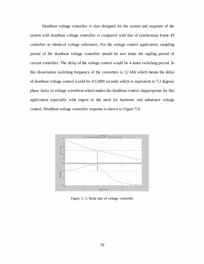
79
Deadbeat voltage controller is also designed for the system and response of the
system with deadbeat voltage controller is compared with that of synchronous frame PI
controller to identical voltage references. For the voltage control application, sampling
period of the deadbeat voltage controller should be two times the sapling period of
current controller. The delay of the voltage control would be 4 times switching period. In
this dissertation switching frequency of the converters is 12 kHz which means the delay
of deadbeat voltage control would be 4/12000 seconds which is equivalent to 7.2 degrees
phase delay in voltage waveform which makes the deadbeat control inappropriate for this
application especially with regard to the need for harmonic and unbalance voltage
control. Deadbeat voltage controller response is shown in Figure 5.9.
Figure 5. 5. Bode plot of voltage controller
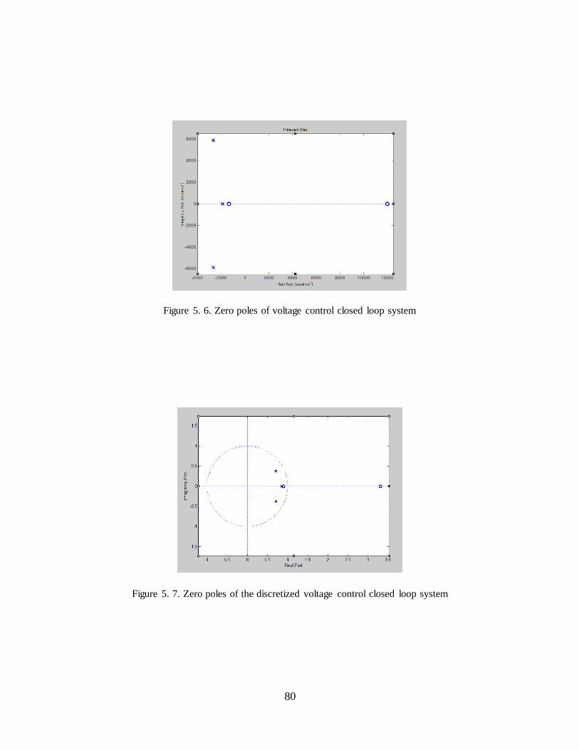
80
Figure 5. 6. Zero poles of voltage control closed loop system
Figure 5. 7. Zero poles of the discretized voltage control closed loop system

81
Figure 5. 8. Response of the designed PI voltage controller
Figure 5. 9. Response of deadbeat voltage controller for this system
5.3 VIRTUAL IMPEDANCE LOOP
Figure 5.10 shows the control loop for virtual impedance implementation. In this
loop, is closed loop transfer function of voltage controller and converter
system. is transfer function of a second order low-pass filter with cut-off
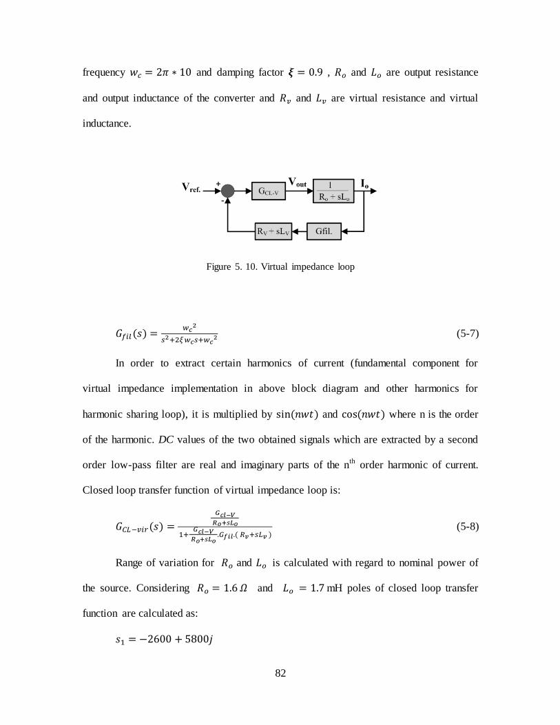
82
frequency and damping factor , and are output resistance
and output inductance of the converter and and are virtual resistance and virtual
inductance.
Figure 5. 10. Virtual impedance loop
(5-7)
In order to extract certain harmonics of current (fundamental component for
virtual impedance implementation in above block diagram and other harmonics for
harmonic sharing loop), it is multiplied by and where n is the order
of the harmonic. DC values of the two obtained signals which are extracted by a second
order low-pass filter are real and imaginary parts of the nth order harmonic of current.
Closed loop transfer function of virtual impedance loop is:
(5-8)
Range of variation for and is calculated with regard to nominal power of
the source. Considering and mH poles of closed loop transfer
function are calculated as:
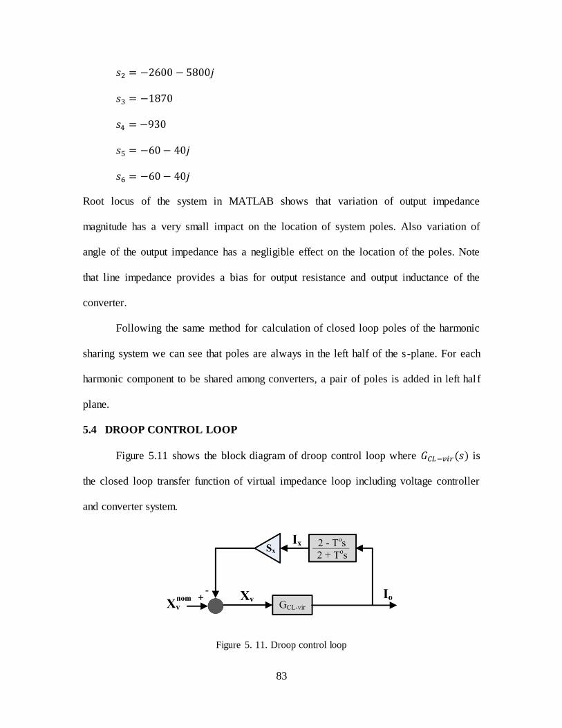
83
Root locus of the system in MATLAB shows that variation of output impedance
magnitude has a very small impact on the location of system poles. Also variation of
angle of the output impedance has a negligible effect on the location of the poles. Note
that line impedance provides a bias for output resistance and output inductance of the
converter.
Following the same method for calculation of closed loop poles of the harmonic
sharing system we can see that poles are always in the left half of the s-plane. For each
harmonic component to be shared among converters, a pair of poles is added in left hal f
plane.
5.4 DROOP CONTROL LOOP
Figure 5.11 shows the block diagram of droop control loop where is
the closed loop transfer function of virtual impedance loop including voltage controller
and converter system.
Figure 5. 11. Droop control loop
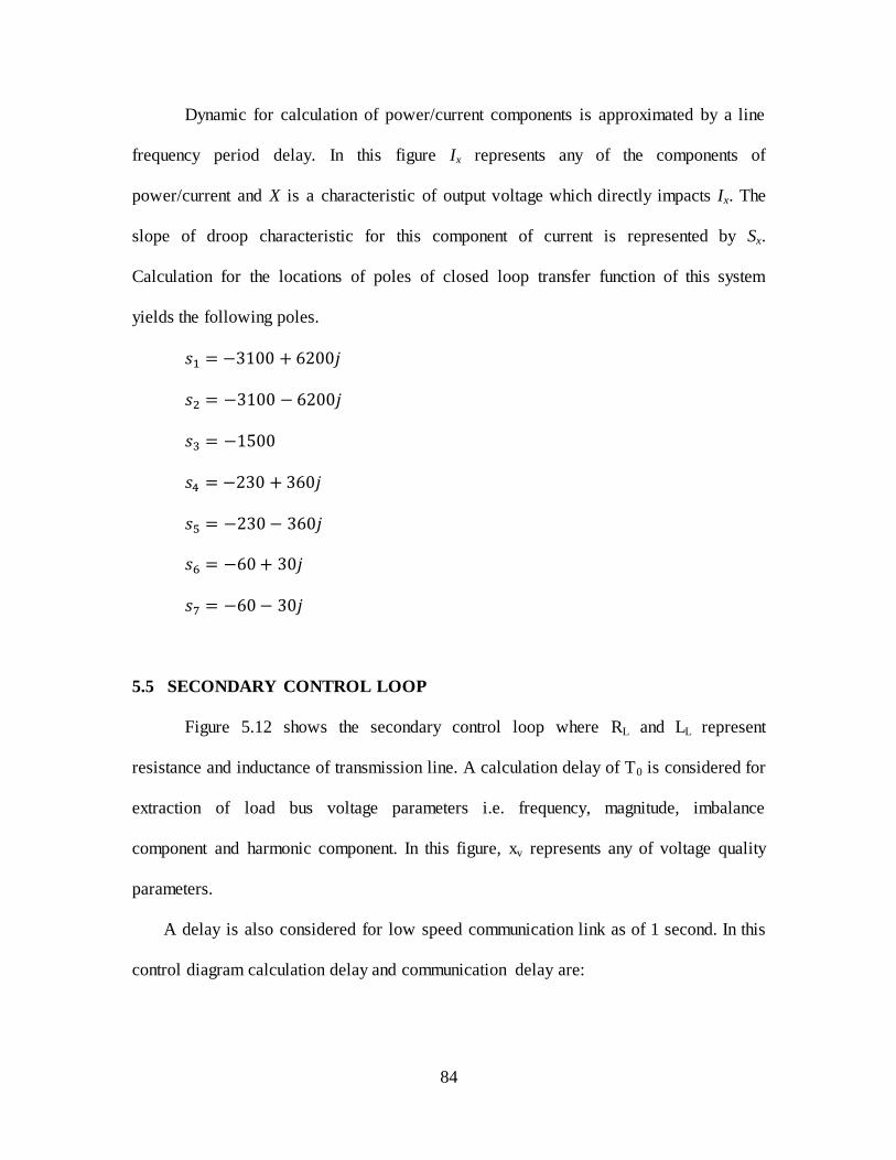
84
Dynamic for calculation of power/current components is approximated by a line
frequency period delay. In this figure Ix represents any of the components of
power/current and X is a characteristic of output voltage which directly impacts Ix. The
slope of droop characteristic for this component of current is represented by Sx.
Calculation for the locations of poles of closed loop transfer function of this system
yields the following poles.
5.5 SECONDARY CONTROL LOOP
Figure 5.12 shows the secondary control loop where RL and LL represent
resistance and inductance of transmission line. A calculation delay of T0 is considered for
extraction of load bus voltage parameters i.e. frequency, magnitude, imbalance
component and harmonic component. In this figure, xv represents any of voltage quality
parameters.
A delay is also considered for low speed communication link as of 1 second. In this
control diagram calculation delay and communication delay are:
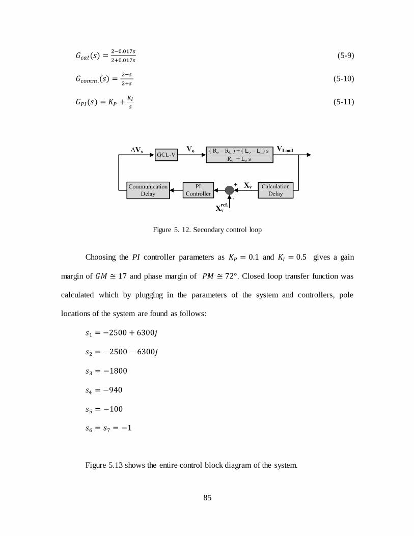
85
(5-9)
(5-10)
(5-11)
Figure 5. 12. Secondary control loop
Choosing the PI controller parameters as and gives a gain
margin of ≅ and phase margin of ≅ . Closed loop transfer function was
calculated which by plugging in the parameters of the system and controllers, pole
locations of the system are found as follows:
Figure 5.13 shows the entire control block diagram of the system.
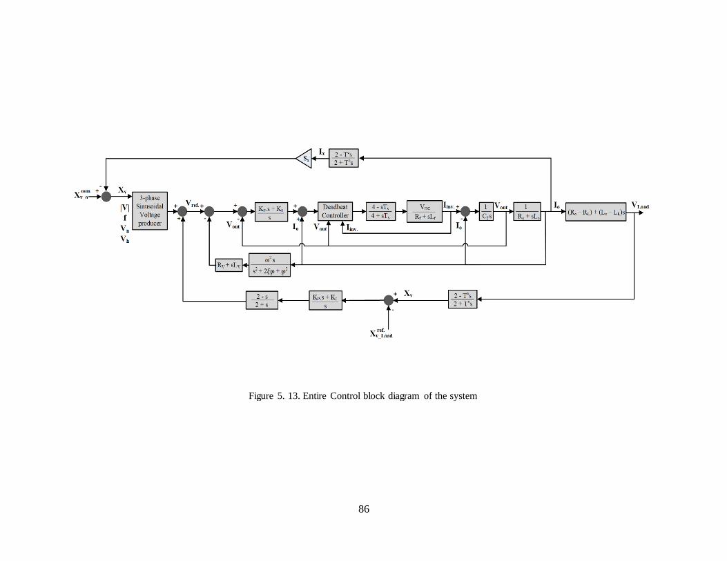
86
Figure 5. 13. Entire Control block diagram of the system
87
5.6 SUMMARY
Stability of the control approach that is presented in this dissertation was analyzed
and control parameters were designed in this chapter. Performance of the controllers was
compared with other types of controllers when appropriate. For current controller,
voltage controller, droop control loop, as well as the secondary control loop, the closed
loop transfer function was computed and pole locations were calculated. Analyses
showed that the proposed control system is stable for the entire range of operating points.
88
CHAPTER VI
MICROGRID OPTIMIZATION IN THE PRESENCE OF STORAGE, PV AND WIND
POWER UNITS
In grid-connected mode of operation, the objective of a microgrid is to export a
controlled amount of active and reactive power into an established voltage. This is
performed through the control of active and reactive components of current in the
current-source mode of converter operation. The power demands themselves come from
the Management System of the microgrid with the exception of Photo Voltaic, heat-led
CHP1 sources, wind power units and storage systems, which generate autonomously [2].
These types of power sources follow the active power reference generated by an internal
control system such as MPPT2 system or SOC3 controller. Whereas the task in grid-
connected mode is to control current into an established voltage, the task in autonomous
mode is to establish that voltage by operation of the converters in voltage-source mode.
Optimization of an autonomous microgrid by sharing each power/current
component was presented in chapter II and III. In order to share power/current
components of the load among converters, output voltage of converters, which are
operating as voltage sources, are manipulated and set through sharing control loops.
Generation of power/current components by converters in the microgrid is proportional to
their sharing coefficient. The exact amount of generation of power/current components
1 Combined Heat and Power
2 Maximum Power Point Tracking
3 State Of Charge

89
by each converter depends on the existing load and cannot be set by sharing coefficients,
whereas for some types of power sources such as PV1, wind power units, and storage
systems there are local criteria for active power/current generation which have priority
over global optimization function. These criteria might be increase of efficiency through
MPPT system, Maintaining SOC of the battery in storage system, etc. These types of
units can be operated in current-source mode so they can follow active power generation
commanded by local control system; however in this mode they lose the coordination
with other converters for sharing other components of power/current. This may lead to
either the requirement for installation of parallel converters to provide reactive, harmonic,
and unbalance current, or the occupancy of the capacity of the other interface converters
which results in less capacity for active power generation by those power sources. In this
chapter, a variable droop control scheme is proposed which allows the active current for
interface converters of PV, wind power sources and storage systems be set to the value
which is computed locally according to the information received about weather, battery
SOC, etc. while those inverters contribute in the generation of the other components of
the current with other converters according to the sharing factors that are set by the
Management System toward a global optimization function. The rest of demanded active
current is shared among other types of power sources.
6.1 POWER UNITS WITH LOCALLY CONTROLLED ACTIVE POWER
6.1.1 PhotoVoltaic
This type of power source consists of converting energy from sunlight to
electrical power by means of photo cells which are connected together in modules or
arrays. The efficiency of PhotoVoltaic power source is between 10%-15% [57]. Output
1 PhotoVoltaics

90
voltage of photo cell modules or arrays is a DC voltage that is generally required to be
boosted to a higher level before being applied to the inverter. Figure 6.1 shows a general
configuration of a PhotoVoltaic system.
There is a control system that according to weather condition sets the parameters
for output voltage and current of the source in order to optimize the operation by
extracting the maximum amount of power from the array at each weather condition. This
control is called Maximum Power Point Tracking system. MPPT system command may
affect either boosting DC-DC converter or the interfacing inverter. If MPPT output signal
is sent to DC-DC converter, this converter transmits the requested active power from
photo cells to DC bus. Interfacing inverter would be in charge of controlling the DC bus
voltage level and supplying the power from DC side to AC grid. It is usually operated in
current-source mode assuming that the AC voltage is strong enough already. In the case
when MPPT system sends active power reference to DC-AC converter, this converter
transmits the requested active power from a constant-voltage DC bus to AC grid where
DC-DC converter is responsible to provide a constant voltage on the DC bus by
transmitting the required power, which is equivalent to output power of inverter in steady
state, from photo cells and battery to DC bus.
Figure 6. 1. PhotoVoltaic power source
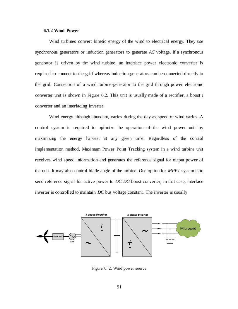
91
6.1.2 Wind Power
Wind turbines convert kinetic energy of the wind to electrical energy. They use
synchronous generators or induction generators to generate AC voltage. If a synchronous
generator is driven by the wind turbine, an interface power electronic converter is
required to connect to the grid whereas induction generators can be connected directly to
the grid. Connection of a wind turbine-generator to the grid through power electronic
converter unit is shown in Figure 6.2. This unit is usually made of a rectifier, a boost i
converter and an interfacing inverter.
Wind energy although abundant, varies during the day as speed of wind varies. A
control system is required to optimize the operation of the wind power unit by
maximizing the energy harvest at any given time. Regardless of the control
implementation method, Maximum Power Point Tracking system in a wind turbine unit
receives wind speed information and generates the reference signal for output power of
the unit. It may also control blade angle of the turbine. One option for MPPT system is to
send reference signal for active power to DC-DC boost converter, in that case, interface
inverter is controlled to maintain DC bus voltage constant. The inverter is usually
Figure 6. 2. Wind power source
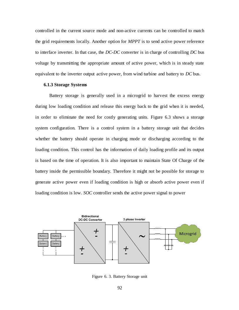
92
controlled in the current source mode and non-active currents can be controlled to match
the grid requirements locally. Another option for MPPT is to send active power reference
to interface inverter. In that case, the DC-DC converter is in charge of controlling DC bus
voltage by transmitting the appropriate amount of active power, which is in steady state
equivalent to the inverter output active power, from wind turbine and battery to DC bus.
6.1.3 Storage Systems
Battery storage is generally used in a microgrid to harvest the excess energy
during low loading condition and release this energy back to the grid when it is needed,
in order to eliminate the need for costly generating units. Figure 6.3 shows a storage
system configuration. There is a control system in a battery storage unit that decides
whether the battery should operate in charging mode or discharging according to the
loading condition. This control has the information of daily loading profile and its output
is based on the time of operation. It is also important to maintain State Of Charge of the
battery inside the permissible boundary. Therefore it might not be possible for storage to
generate active power even if loading condition is high or absorb active power even if
loading condition is low. SOC controller sends the active power signal to power
Figure 6. 3. Battery Storage unit
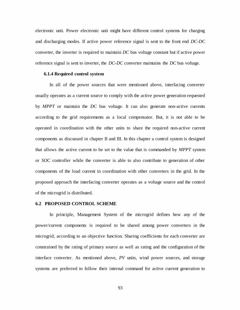
93
electronic unit. Power electronic unit might have different control systems for charging
and discharging modes. If active power reference signal is sent to the front end DC-DC
converter, the inverter is required to maintain DC bus voltage constant but if active power
reference signal is sent to inverter, the DC-DC converter maintains the DC bus voltage.
6.1.4 Required control system
In all of the power sources that were mentioned above, interfacing converter
usually operates as a current source to comply with the active power generation requested
by MPPT or maintain the DC bus voltage. It can also generate non-active currents
according to the grid requirements as a local compensator. But, it is not able to be
operated in coordination with the other units to share the required non-active current
components as discussed in chapter II and III. In this chapter a control system is designed
that allows the active current to be set to the value that is commanded by MPPT system
or SOC controller while the converter is able to also contribute to generation of other
components of the load current in coordination with other converters in the grid. In the
proposed approach the interfacing converter operates as a voltage source and the control
of the microgrid is distributed.
6.2 PROPOSED CONTROL SCHEME
In principle, Management System of the microgrid defines how any of the
power/current components is required to be shared among power converters in the
microgrid, according to an objective function. Sharing coefficients for each converter are
constrained by the rating of primary source as well as rating and the configuration of the
interface converter. As mentioned above, PV units, wind power sources, and storage
systems are preferred to follow their internal command for active current generation to
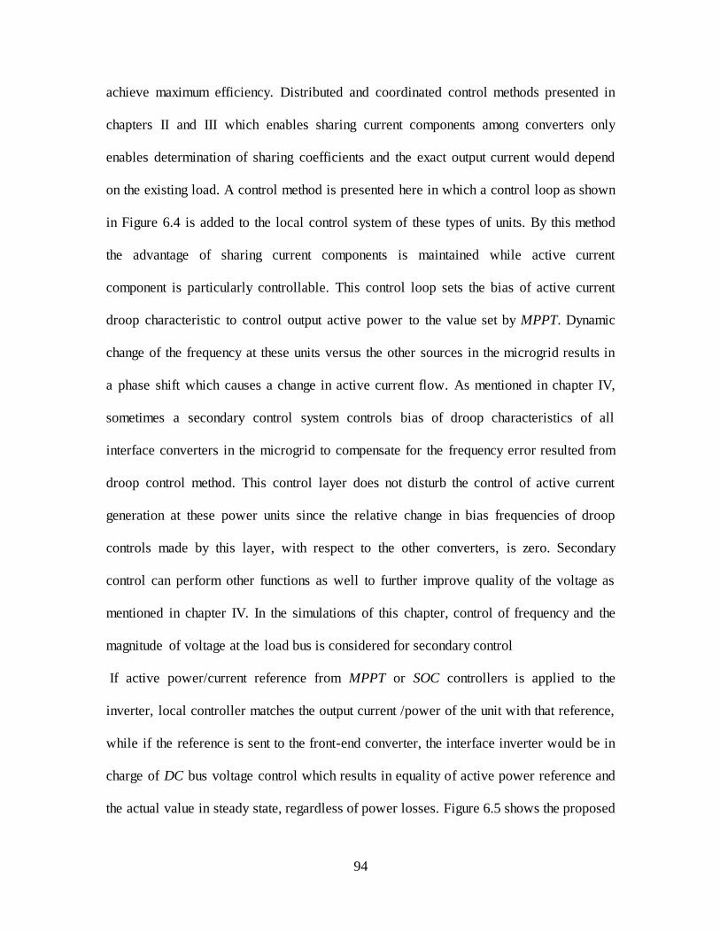
94
achieve maximum efficiency. Distributed and coordinated control methods presented in
chapters II and III which enables sharing current components among converters only
enables determination of sharing coefficients and the exact output current would depend
on the existing load. A control method is presented here in which a control loop as shown
in Figure 6.4 is added to the local control system of these types of units. By this method
the advantage of sharing current components is maintained while active current
component is particularly controllable. This control loop sets the bias of active current
droop characteristic to control output active power to the value set by MPPT. Dynamic
change of the frequency at these units versus the other sources in the microgrid results in
a phase shift which causes a change in active current flow. As mentioned in chapter IV,
sometimes a secondary control system controls bias of droop characteristics of all
interface converters in the microgrid to compensate for the frequency error resulted from
droop control method. This control layer does not disturb the control of active current
generation at these power units since the relative change in bias frequencies of droop
controls made by this layer, with respect to the other converters, is zero. Secondary
control can perform other functions as well to further improve quality of the voltage as
mentioned in chapter IV. In the simulations of this chapter, control of frequency and the
magnitude of voltage at the load bus is considered for secondary control
If active power/current reference from MPPT or SOC controllers is applied to the
inverter, local controller matches the output current /power of the unit with that reference,
while if the reference is sent to the front-end converter, the interface inverter would be in
charge of DC bus voltage control which results in equality of active power reference and
the actual value in steady state, regardless of power losses. Figure 6.5 shows the proposed

95
control loop added to inverter control system when active power reference is applied to
the front-end converter.
Figure 6. 4. Output active current control loop - Reference directly sent to interface inverter
Figure 6. 5. DC voltage control loop - Reference sent to front-end converter
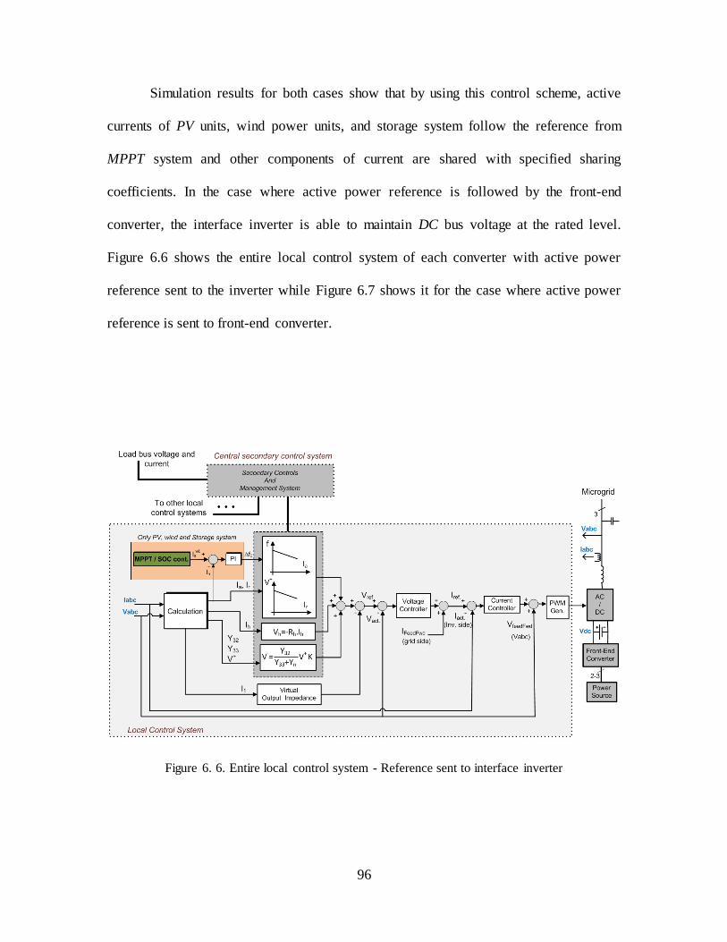
96
Simulation results for both cases show that by using this control scheme, active
currents of PV units, wind power units, and storage system follow the reference from
MPPT system and other components of current are shared with specified sharing
coefficients. In the case where active power reference is followed by the front-end
converter, the interface inverter is able to maintain DC bus voltage at the rated level.
Figure 6.6 shows the entire local control system of each converter with active power
reference sent to the inverter while Figure 6.7 shows it for the case where active power
reference is sent to front-end converter.
Figure 6. 6. Entire local control system - Reference sent to interface inverter

97
Figure 6. 7. Entire local control system - Reference sent to front-end converter
6.3 SIMULATION RESULTS
The proposed control scheme has been applied to a microgrid comprised of two
converter-interfaced power sources which are connected to a load center through
transmission lines. One of the sources is a Photo Voltaic energy source and the other one
is a micro-turbine generator set. The load center consists of a constant balanced load and
a switched load which includes balanced, unbalanced as well as harmonic load. Figure
6.8 shows the simulated microgrid. Table 1 shows the circuit parameters of the microgrid
which are used in the simulation. Management System sets the sharing coefficients for
each current component. PV unit generates active current in accordance with the MPPT
system and shares the other components of the load with the sharing coefficients set by
Management System. Secondary control sets bias of droop characteristics for active and
reactive current to control frequency and voltage magnitude at the load bus. For the
converters, interface converter of PV source is able to generate twice as much harmonic

98
Figure 6. 8. The simulated microgrid
simulation shown in this chapter no specific optimization function is considered. It is
assumed that due to different structures as well as switching frequencies of the interface
Table 6.1. Parameters of the simulated system
DC bus voltage: 700V Line impedance:
0.754+0.377j
AC bus rated RMS
voltage (phase):
120V Virtual
impedance:
0.754+0.377j
AC bus rated frequency:
60Hz Constant loads:
22.5kW + 22.5kVar
Switching frequency: 12kHz Switched Load:
Unbalanced load of 12kW + 8kVar and a thyristor rectifier with firing angle of 30 degrees
LC filter inductance: 1mH Load Switching times
Case 1: t=0.5 s (switching on) and t=1.5 s (switching off) Case 2: t=1 s (switching on) and t=4 s (switching off)
LC filter capacitance: 123uF Strategy of the sharing control:
Harmonics with the ratio of 1/2, unbalance current with the ratio of 2/1 and reactive current equally. Active current of PV is controlled by
MPPT which varied during the simulation, and the other source generates the rest.

99
as the other converter generates, but due to a smaller capacitor on the DC bus, it is set to
generate half as much unbalance current as the other one generates to reduce ripple on the
DC bus voltage. Reactive current is set to be shared equally between the two converters.
Case 1: In the case 1 of the simulations active power reference from MPPT is
sent to the interface inverter and DC bus is assumed to be controlled by the front-end
unit. Active current of PV source follows the MPPT command which varies from t=3 S to
t=3.5 S and the other source is expected to supply the rest of demanded active current.
The switched load is switched in at t=0.5 S and switched out at t=1.5 S. Figure 6.9 shows
the active current of the two sources along with the MPPT reference for PV active
current. It can be seen that PV follows the MPPT command regardless of the value of the
load and the other source supplies the rest of the demanded load. When MPPT command
changes from 75 A to 125 A the other source changes its output active current in the
opposite way to keep the balance between load and generation. Figures 6.10, 6.11, and
6.12 show reactive, harmonic and unbalance current sharing between the two sources,
both with and without the switched load. It can be seen that sharing of the other
components is done with the sharing coefficients requested by the Management System
which are shown in table 1. Figure 6.13 and 6.14 show magnitude and frequency of the
voltage at load bus. It can be seen that by the performance of the secondary control
voltage magnitude deviation from 120 V and frequency deviation from 60 Hz are always
compensated. Secondary control which works by setting the bias of active and reactive
current droop characteristics does not disturb the performance of the active current
control for PV source.
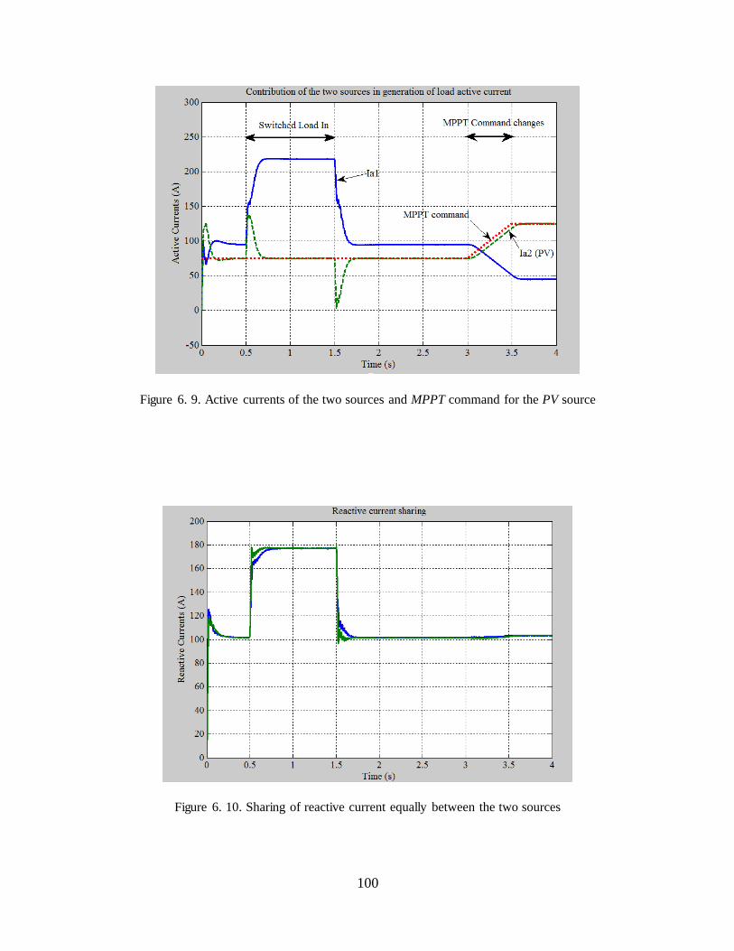
100
Figure 6. 9. Active currents of the two sources and MPPT command for the PV source
Figure 6. 10. Sharing of reactive current equally between the two sources

101
Figure 6. 11. Sharing of harmonics between the two sources; PV interface converter generates
twice as the other interface converter
Figure 6. 12. Sharing of unbalance current between the two sources; PV interface converter
generates half as much as the other interface converter
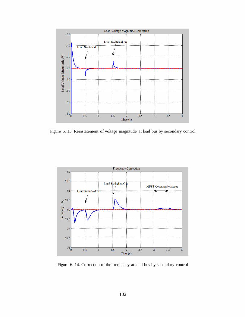
102
Figure 6. 13. Reinstatement of voltage magnitude at load bus by secondary control
Figure 6. 14. Correction of the frequency at load bus by secondary control
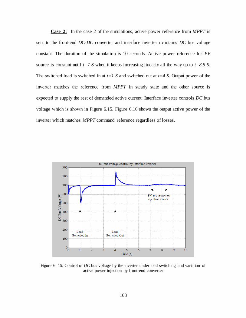
103
Case 2: In the case 2 of the simulations, active power reference from MPPT is
sent to the front-end DC-DC converter and interface inverter maintains DC bus voltage
constant. The duration of the simulation is 10 seconds. Active power reference for PV
source is constant until t=7 S when it keeps increasing linearly all the way up to t=8.5 S.
The switched load is switched in at t=1 S and switched out at t=4 S. Output power of the
inverter matches the reference from MPPT in steady state and the other source is
expected to supply the rest of demanded active current. Interface inverter controls DC bus
voltage which is shown in Figure 6.15. Figure 6.16 shows the output active power of the
inverter which matches MPPT command reference regardless of losses.
Figure 6. 15. Control of DC bus voltage by the inverter under load switching and variation of
active power injection by front-end converter
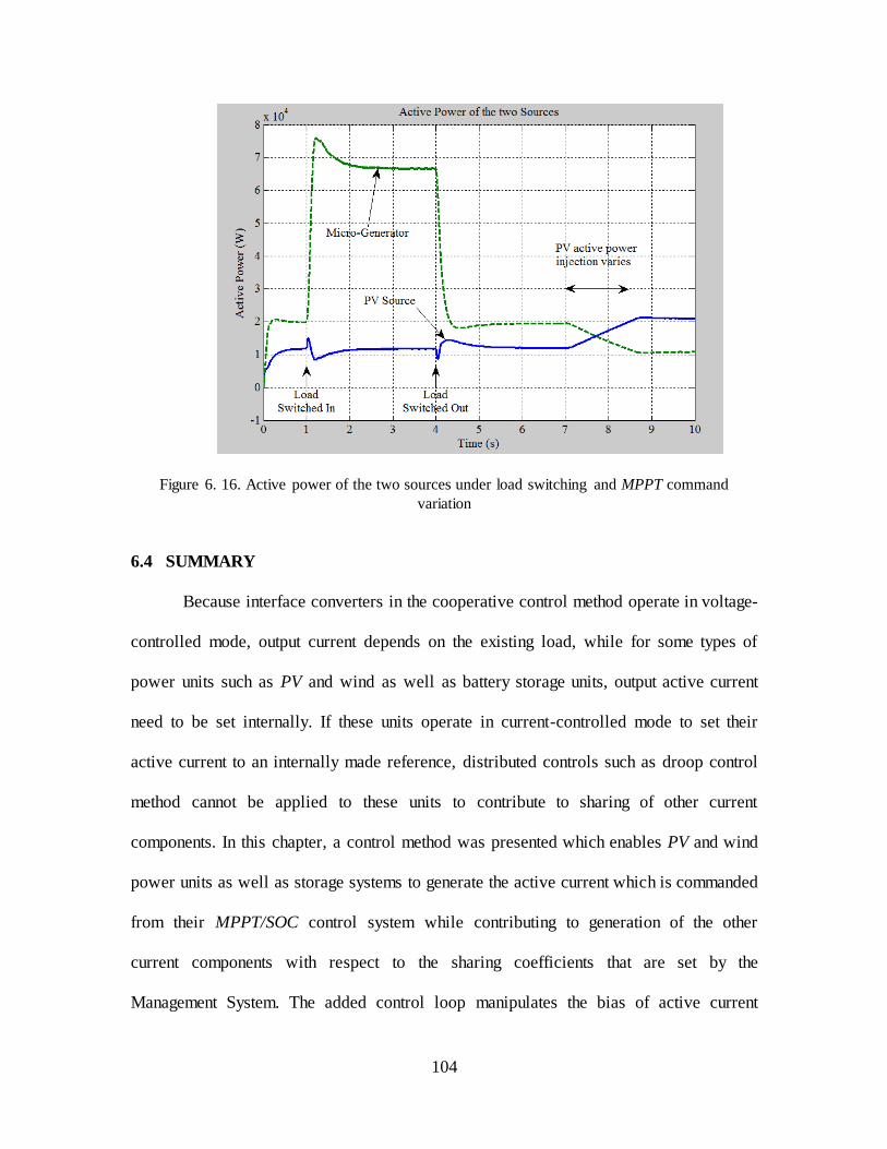
104
Figure 6. 16. Active power of the two sources under load switching and MPPT command
variation
6.4 SUMMARY
Because interface converters in the cooperative control method operate in voltage-
controlled mode, output current depends on the existing load, while for some types of
power units such as PV and wind as well as battery storage units, output active current
need to be set internally. If these units operate in current-controlled mode to set their
active current to an internally made reference, distributed controls such as droop control
method cannot be applied to these units to contribute to sharing of other current
components. In this chapter, a control method was presented which enables PV and wind
power units as well as storage systems to generate the active current which is commanded
from their MPPT/SOC control system while contributing to generation of the other
current components with respect to the sharing coefficients that are set by the
Management System. The added control loop manipulates the bias of active current

105
droop characteristics to set the output active current as required. The secondary control
also adjusts the bias of active and reactive current droop characteristics to control
frequency and voltage magnitude at load bus, but this does not disturb the active current
control as the relative change in the bias of active current droop characteristics of
converters made by secondary control is zero. If active power reference is applied to the
front-end converter, that converter will function like a current source to the DC bus.
Then, interface converter would have the duty of maintaining DC bus voltage at the
required level. Simulation results show the validity of the presented control scheme.

106
CHAPTER VII
MICROGRID POWER MANAGEMENT SYSTEM
Coordinated control of converters in a microgrid was presented in previous chapters and
it was shown how converters in an autonomous microgrid can share components of
power /current without any communication with each other. It was also shown that
converters can improve the quality of load bus voltage by operating in cooperation
through secondary control. Control of converter current based on CPC power theory
enables the microgrid to independently share current components among converters such
that each power source generates different ratio of each current component as shown in
Figure 7.1 which might be required for optimization of various parameters in a microgrid.
Figure 7. 1. Independent sharing of each current component

107
The scope of a microgrid's operational objective is not limited to simply meeting
local power demands, but also considering factors such as emissions, fuel availability and
cost, weather conditions, the spot-market price of electricity, etc. [58]. In another words
there are local objectives such as feeding the loads as well as system-level objectives
such as stability, reliability and cost [59]. System-level objective functions or
optimization functions determine the coordination among converters. In order to
automatically set the coordination among converters and reset the sharing factors after
any change in the configuration of the microgrid or operating condition of the system, a
Management System is required so the system always remains optimum with no need for
human intervention. Control topology should be arranged in a way that ensures proper
coordination of sources throughout the microgrid with regard to the optimization
function. In some microgrid control configurations such as in [58] and [60] local controls
can talk together through a platform and no system-level control is utilized. In the
distributed control of an autonomous microgrid described in this dissertation, there is a
system-level control as well as local controls such as in [59]. In this scheme, local control
systems operate autonomously but their setting for current component sharing is reset by
the system-level control following any changes in the operating condition of the
microgrid. The speed of data transfer between local and system-level control doesn’t
need to be very fast, therefore a low-bandwidth communication link would be enough for
data transfer. PMS1 in system-level control should be able to [61]
- efficiently share current components among power sources,
1 Power Management System

108
- quickly responds to disturbances and transients due to changes in the system
operating mode,
- determine the final power generation set-points of the DGs to balance power
and restore frequency of the system,
- provide means of resynchronization with the main grid.
In this chapter, different optimization functions for a Management System will be
reviewed and the most popular one will be extended and a mathematical representation of
that by the use of CPC power theory will be given along with simulation results. Such an
algorithm can be developed for other optimization functions as well by making use of
CPC theory.
7.1 OPTIMIZATION FUNCTIONS
Most of the optimization functions in previous works such as in [21, 23, 62] have
focused on sharing only active and reactive powers among power supplies; however,
optimization of the microgrid may require control over all major current components. In
[62] harmonic and unbalanced components are supplied by some specific converters in
the grid which are called compensators. These components are not shared among all
power converters as might be required for some optimization purposes. Authors in [63]
have recently used programmable resistive behavior to share harmonics with optimization
purpose of equal power loading. PMS in [64] shares active and reactive power among
inverter-connected sources in the microgrid using virtual frequency-voltage frame droop
control.
Various objective functions can be considered in the optimization of a microgrid.
These include [58, 61, 65, 59]

109
- Equal per-unit power loading of the units,
- Minimization of economic factors such as fuel cost, operation and maintenance cost,
start-up/shut-down cost,
- Maximizing the customer’s power availability and/or power quality,
- Minimization of environmental impacts from the generators,
- Minimization of total power loss,
- Maximizing the total efficiency of the microgrid; kWh generated energy per kJ fule
consumed,
- Improving the dynamic response and maintaining stability margins during and after
transients.
Minor objective functions may also be considered such as
- Minimization of the need for storage system by maximizing load factor (smooth out
peaks and valleys of the load),
- Maximizing Var support to the greater grid when operating in grid-connected mode,
- Generation of reactive power as close as possible to the load to reduce power loss,
- Minimizing the number of converters involved.
Among these, ―equal loading utilization‖, ―power loss minimization‖, ―fewer
converters involved‖, and ―larger converters involved‖ have been more commonly used
[59]. There are also constraints that should be considered during the optimization, such as
power availability of a renewable resource, bus voltage and frequency requirements,
equality of load and supplies, and physical electrical characteristics of the microgrid.

110
Constraints arising from phase current limits and avoidance of over-modulation may be
accounted for by more complex constraint functions.
Considering the independent controllability of harmonic and unbalance current,
other minor objective functions may be considered during the optimization process.
These include
- a higher share of generation of harmonic and unbalanced currents by the converters
which are electrically closer to the loads to prevent deterioration of voltage quality at
load bus,
- a higher share of generation of unbalanced currents by converters with larger DC bus
capacitor to reduce ripple on DC bus voltage
- generation of reactive, harmonic and unbalance current by interface converters of PV
and wind power sources to fully utilize them when active power generation is far
below ratings,
- Improvement of voltage THD and voltage imbalance at critical load buses.
Constraints for the generation of harmonic and unbalanced currents are maximum
unbalanced current of the converter, maximum harmonic current of the converter,
microgrid voltage quality, allowable DC bus voltage ripple, etc. In the optimization
process, other sources of current components such as compensators also need to be
controlled in coordination with interface converters in order to contribute in generation of
some or all of the current components [66]. Interface converters need, at the minimum, to
have high enough ratings to supply the active rated power of the prime-mover, but the
final ratings need to be somewhat higher to be able to supply the necessary reactive

111
power [67]. Considering harmonic and unbalance power necessitates even higher ratings
for interface converters. Energy storage should be provided to ensure the immediate
availability of energy for the load. The rating of the storage system depends on the
technology of the prime mover [67].
7.2 CONSIDERED OPTIMIZATION FUNCTION
In this chapter ―equal loading utilization‖ which is more commonly used for
active and reactive power sharing is extended to all major current components.
Constraints such as rating and configuration of the converters and rating of the primary
sources as well as active current command from MPPT system of PV and wind turbine
power sources have been considered.
Microgrids may contain fuel cells, wind turbines, PV units, micro-turbines and
hydrogen power sources that are connected through interface converters along with
compensating converters which can contribute to the generation of non-active current
components.
The objective can be explained as follows:
Power units with local reference generation for active current, such as wind power
units and PV units follow their local active current reference to increase the efficiency
of the unit.
The additional required active current for loads will be supplied by the other units
with respect to the rating of the primary power supply.
Reactive current of the load will be supplied by interface converters as well as
compensating converters, with respect to their remaining capacity.
112
Harmonic and unbalanced current are shared among all converters in the microgrid
according to their remaining capacity after the last step. If this lowers power quality
at a load bus below a certain limit, converters which are electrically closer to that load
bus will generate a larger portion of harmonic and unbalance to avoid voltage
distortion and imbalance due to harmonic and unbalance current transmission. Also, it
may be preferred that converters with larger energy storage on the DC bus, generate a
larger portion of unbalance current to reduce ripple on the DC bus voltage.
Constraints: Physical limitation of the microgrid characteristics, namely power
rating of generating units and current rating of semiconductor devices, is the primary
constraint. Equality of loads and supplies is always considered during the solution of
the optimization function.
7.3 MATHEMATICAL REPRESENTATION
Current components are calculated for each source in the microgrid according to
the optimization function.
a. Calculation of active current shares
Active currents of PV, wind, and storage systems, ,
, and , are
determined by their local controllers. Additional demanded active current should be
supplied by other units.
(7-1)
where N1 is the number of all generating units other than PV, wind and storage systems.
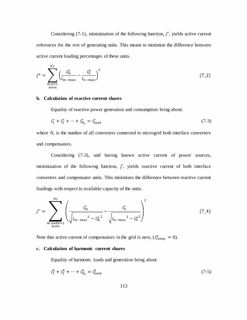
113
Considering (7-1), minimization of the following function, ja, yields active current
references for the rest of generating units. This means to minimize the difference between
active current loading percentages of these units.
∑ (
)
b. Calculation of reactive current shares
Equality of reactive power generation and consumption bring about:
(7-3)
where Nc is the number of all converters connected to microgrid both interface converters
and compensators.
Considering (7-3), and having known active current of power sources,
minimization of the following function, jr, yields reactive current of both interface
converters and compensator units. This minimizes the difference between reactive current
loadings with respect to available capacity of the units.
∑
(
√
√
)
Note that active current of compensators in the grid is zero, ( ).
c. Calculation of harmonic current shares
Equality of harmonic loads and generation bring about
(7-5)
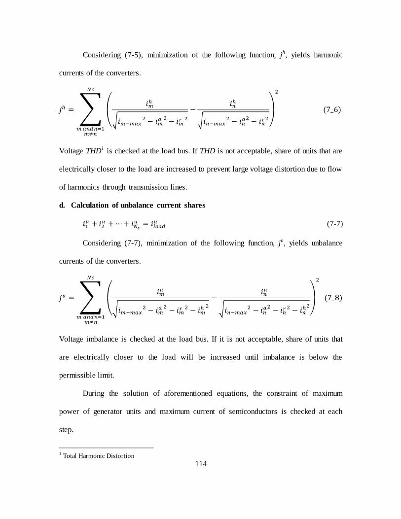
114
Considering (7-5), minimization of the following function, jh, yields harmonic
currents of the converters.
∑
(
√
√
)
Voltage THD1 is checked at the load bus. If THD is not acceptable, share of units that are
electrically closer to the load are increased to prevent large voltage distortion due to flow
of harmonics through transmission lines.
d. Calculation of unbalance current shares
(7-7)
Considering (7-7), minimization of the following function, ju, yields unbalance
currents of the converters.
∑
(
√
√
)
Voltage imbalance is checked at the load bus. If it is not acceptable, share of units that
are electrically closer to the load will be increased until imbalance is below the
permissible limit.
During the solution of aforementioned equations, the constraint of maximum
power of generator units and maximum current of semiconductors is checked at each
step.
1 Total Harmonic Distortion
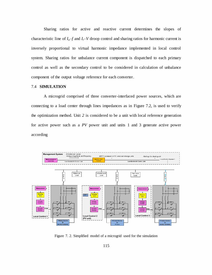
115
Sharing ratios for active and reactive current determines the slopes of
characteristic line of Ia–f and Ir–V droop control and sharing ratios for harmonic current is
inversely proportional to virtual harmonic impedance implemented in local control
system. Sharing ratios for unbalance current component is dispatched to each primary
control as well as the secondary control to be considered in calculation of unbalance
component of the output voltage reference for each converter.
7.4 SIMULATION
A microgrid comprised of three converter-interfaced power sources, which are
connecting to a load center through lines impedances as in Figure 7.2, is used to verify
the optimization method. Unit 2 is considered to be a unit with local reference generation
for active power such as a PV power unit and units 1 and 3 generate active power
according
Figure 7. 2. Simplified model of a microgrid used for the simulation
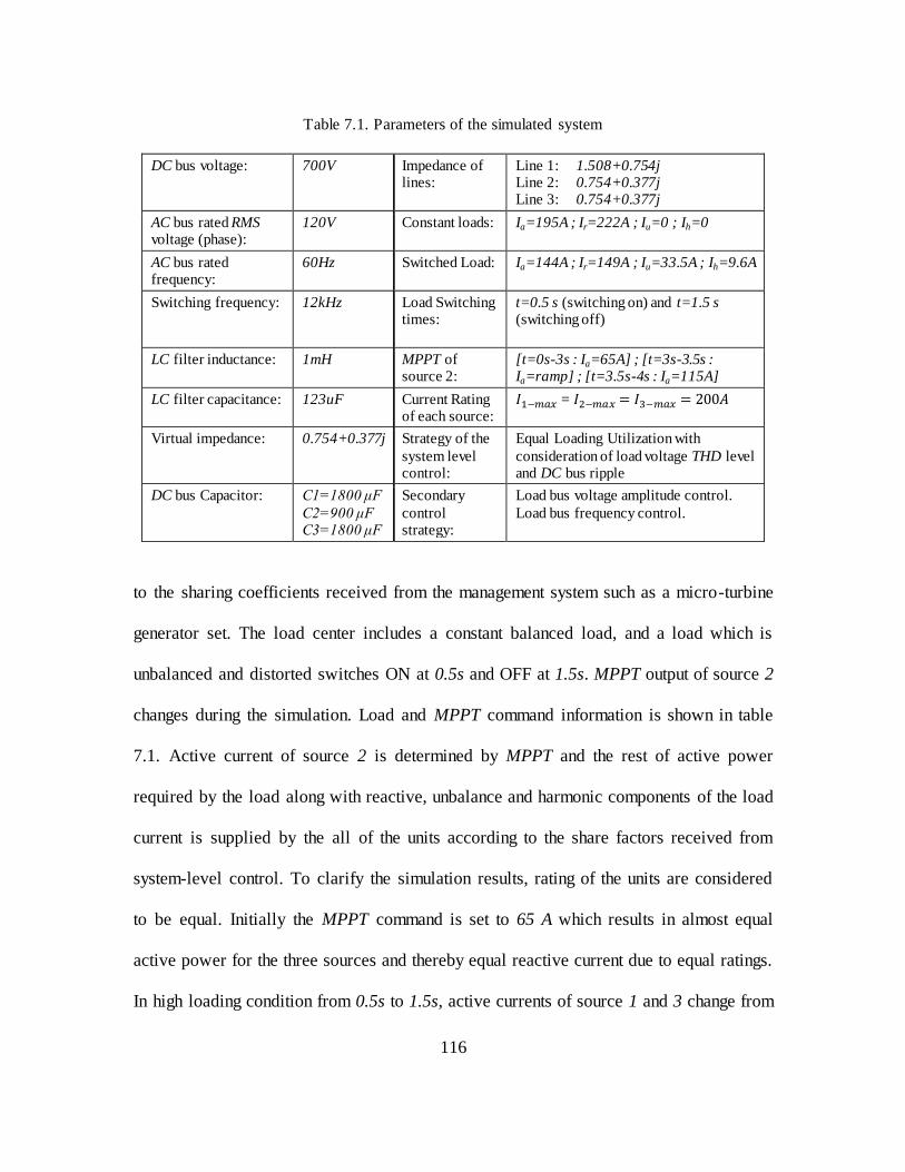
116
Table 7.1. Parameters of the simulated system
DC bus voltage: 700V Impedance of lines:
Line 1: 1.508+0.754j Line 2: 0.754+0.377j Line 3: 0.754+0.377j
AC bus rated RMS voltage (phase):
120V Constant loads: Ia=195A ; Ir=222A ; Iu=0 ; Ih=0
AC bus rated frequency:
60Hz Switched Load: Ia=144A ; Ir=149A ; Iu=33.5A ; Ih=9.6A
Switching frequency: 12kHz Load Switching times:
t=0.5 s (switching on) and t=1.5 s (switching off)
LC filter inductance: 1mH MPPT of source 2:
[t=0s-3s : Ia=65A] ; [t=3s-3.5s : Ia=ramp] ; [t=3.5s-4s : Ia=115A]
LC filter capacitance: 123uF Current Rating of each source:
=
Virtual impedance: 0.754+0.377j Strategy of the
system level control:
Equal Loading Utilization with
consideration of load voltage THD level and DC bus ripple
DC bus Capacitor: C1=18 μF
C2= μF C3=18 μF
Secondary
control strategy:
Load bus voltage amplitude control.
Load bus frequency control.
to the sharing coefficients received from the management system such as a micro-turbine
generator set. The load center includes a constant balanced load, and a load which is
unbalanced and distorted switches ON at 0.5s and OFF at 1.5s. MPPT output of source 2
changes during the simulation. Load and MPPT command information is shown in table
7.1. Active current of source 2 is determined by MPPT and the rest of active power
required by the load along with reactive, unbalance and harmonic components of the load
current is supplied by the all of the units according to the share factors received from
system-level control. To clarify the simulation results, rating of the units are considered
to be equal. Initially the MPPT command is set to 65 A which results in almost equal
active power for the three sources and thereby equal reactive current due to equal ratings.
In high loading condition from 0.5s to 1.5s, active currents of source 1 and 3 change from

117
65 A to 137 A to supply the load and active current of PV source remains unchanged in
steady state due to the unchanged MPPT command. Reactive currents of three sources
change according to (7-4). Reactive current of sources 1 and 3 which was initially 74 A
increases to 112.5 A and that of source 2 which was also initially 74 A, increases to 146
A. From 3.5s to 4s when with light loading condition, MPPT command changes, the
solution of optimization function keeps being updated and therefore active and reactive
current of the three sources change until MPPT command is constant again. The new
active current of source 2 is 115 A and that of sources 1 and 3 decreases to 40 A to
balance the load and generation. During this time a shift of reactive current load from
source 2 to source 1 and 3 occurs to satisfy optimization requirements. New reactive
currents of the three sources are 79 A, 64 A, and 79 A. Active and reactive currents of
sources are shown in Figure 7-3 and 7.4. Due to larger impedance of line between source
1 and load, harmonic current of source 1 is set to be half of harmonic current of the other
sources. Also due to a lower value of capacitance on the DC bus of the source 2,
unbalance current of source 2 is set to be half of the unbalance current of the other
sources. Harmonic and Unbalance currents of sources are shown in Figure 7-5 and 7-6.
System-level control also improves magnitude and frequency of load bus voltage after
each load change in the system by changing the bias of droop characteristics of active and
reactive current control. These results are shown in Figure 7.7 and 7.8. Simulation results
show the exact sharing of active, reactive, unbalance and harmonic current components
among sources as well as improvement of the load voltage.
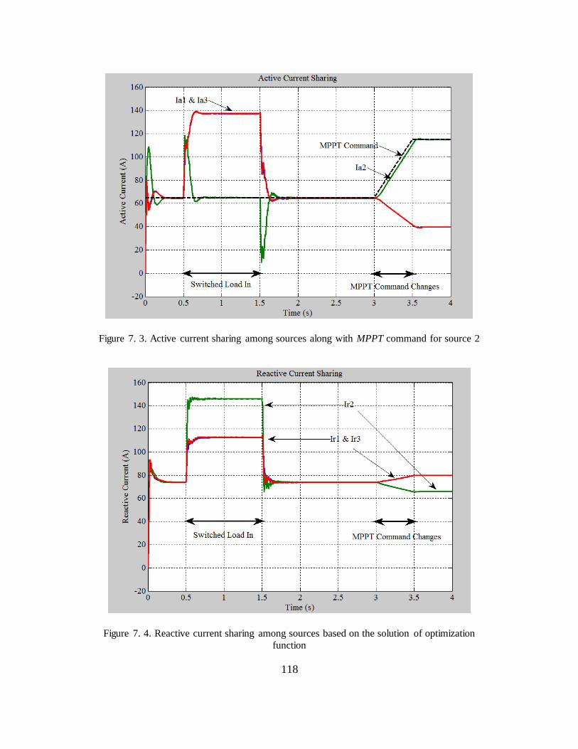
118
Figure 7. 3. Active current sharing among sources along with MPPT command for source 2
Figure 7. 4. Reactive current sharing among sources based on the solution of optimization
function

119
Figure 7. 5. Harmonic current sharing among sources
Figure 7. 6. Unbalanced load sharing among sources
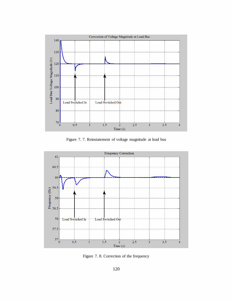
120
Figure 7. 7. Reinstatement of voltage magnitude at load bus
Figure 7. 8. Correction of the frequency
121
7.5 SUMMARY
In order for a microgrid system to stay optimized after any change in the
configuration of the system, operating condition of the micogrid, or constraints for the
microgrid operation, a power management system is required so that it resets the
coordination settings among power units after any such change in the system. The
proposed management system in this chapter, not only coordinates the generation of
active and reactive power among units but also for harmonic and unbalanced currents.
Therefore, units with only non-active current generation capability such as compensators
and active power filters are considered too. The management system calculates the
sharing coefficients according to the considered objective function. It also receives
information of locally made active power reference from units such as PV and wind
power source. A commonly used objective function was considered in this chapter and a
mathematical approach based on CPC power theory was presented. The algorithm can be
established for other objective functions as well. A sample microgrid was simulated and
the results show that generation of each current component is controlled according to the
results of the solution for objective function. Power quality improvement at the load bus
was considered as a minor objective function and magnitude and frequency of voltage
was improved at this bus.
122
CHAPTER VIII
CONCLUSIONS AND FUTURE WORK
8.1 CONCLUSION
In order to optimize various parameters in an autonomous microgrid or in
electrical islands such as shipboard distribution systems, aircraft distribution systems, or
offshore oil/gas platforms, control of power sources should be closely coordinated. This
work proposed a cooperative control method for independent control of load current
components to be shared among sources in a microgrid, so that converters in the
microgrid can contribute to generation of each current component in any percentage. This
cooperative control method is accomplished by utilizing the higher degrees of
controllability of power electronic converters compared to electrical machines, along
with advanced power theories and distributed control methods.
Coordinated control of all major components of the demanded current among
converters allows for an extended degree of optimization of a microgrid’s operation.
Sharing factors for each current component are determined by a management system
considering an objective function as well as constraints such as ability of the interface
power converters to provide each component of current. Converters’ abilities depend on
the availability of primary sources, converter rating, converter structure and switching
frequency. Thus, the constraints will be different for various converters and may even

123
vary over time for a particular converter.
In the distributed control method each interface converter is controlled as a
voltage source where the exact amount of generation of current components by each
converter depends on the existing load as well as the specified share factors. However,
for some types of power sources such as Photo Voltaic, heat-led CHP1 sources, wind
power units and storage systems, the reference value for the active current component is
determined according to a local control system. A control method was also presented in
this dissertation which enables these units to generate active current which is commanded
by MPPT/SOC control system while contributing to generation of the other current
components with regard to the sharing coefficients that are set by the management
system.
Microgrids in autonomous operation are prone to voltage magnitude deviation,
frequency error, imbalance, and harmonic distortion. Load variation has an adverse
impact on the quality of voltage. While any load step generally affects the magnitude of
voltage at the load bus, nonlinear and unbalanced loads cause distortion and imbalance of
the load voltage. The voltage is even deteriorated by performance of the load sharing
units in local control systems due to coordinated control of power sources. A secondary
control layer was designed which receives power quality indices of the load bus and
applies correction signals to each local control system so that in addition to load sharing,
load voltage quality is improved to standard limits.
While control of converters is distributed, a management system is required so
that it resets the coordination settings among power units after any change in the
1 Combined Heat and Power

124
configuration of the system, operating condition of the micogrid, constraints for the
microgrid operation, etc. A mathematical representation of an optimization function was
presented along with simulation results. ―Equal Loading Utilization‖ is the basis for the
optimization function and includes all major current components. By sharing of active
load and ancillary functions such that total current of each converter is in accordance to
its rating, this objective function prevents saturation of a unit while other units have
available capacity for generation of current components. It also prevents unnecessary shut
down of a unit which is usually costly and delays the availability of the unit for
regeneration. All connected converters including units with only non-active current
generation capability such as compensators and active power filters are also considered in
the optimization.
Simulation results for each part of the proposed control approach verify that load
components can be shared according to sharing coefficient dedicated by the management
system with less than 5% error and power quality can be improved according to standard
limits.
8.2 FUTURE WORK
8.2.1 Optimization of power quality throughout the microgrid
In this dissertation, loads are considered to be concentrated at a certain bus, while
in a real microgrid, that might not be true. Here, quality of voltage at a certain bus was
targeted for improvement by the secondary control. If loads are distributed in multiple
buses, according to sensitivity of each set of bus loads, an objective function should be
considered in which power quality of buses are given different weights.

125
8.2.2 Considering other objective functions
Equal loading utilization was specified as the objective and a mathematical
expression to achieve that objective was developed based on CPC power theory. Other
objective functions can be considered based on operational priorities such as power loss
minimization, generation cost minimization, reliability, etc. Thus, expressions for other
objective functions should be developed for the coordination framework developed in
this work.
8.2.3 Comparison among central, master/slave, and distributed control method
in coordinated control of power units
A distributed control method was used in this dissertation for coordination among
sources which has the advantage of independence from communication links and lack of
single point of failure. This control system has its own precision as well as response time.
Also performance of this control scheme was not evaluated in transient states. It would be
worthwhile to compare other types of control systems such as communication based
centralized control and master-slave control based on such metrics as precision, transient
performance, stability margins, etc. Also if the delay due to low bandwidth
communication links had been considered in the simulations of this dissertation, response
time would have increased.
126
REFERENCES
[1] Hassan Farhangi, ―The Path of the Smart Grid‖, IEEE Power and Energy magazine.
2010
[2] T.C.Green, M. Prodanovic "Control of inverter-based micro-grids," Elsevier
electric power system research , pp. 1204-1213, 2007.
[3] I. Vechiu1, A. Llaria, O. Curea and H. Camblong, "Control of Power Converters for
Microgrids," in Ecologiv Vehicles Renewable Energies, Monaco, March 26-29
2009.
[4] Josep M. Guerrero, Juan C. Vasquez, José Matas, Luis García de Vicuña, and
Miguel Castilla, "Hierarchical Control of Droop-Controlled AC and DC
Microgrids—A General Approach Toward Standardization," IEEE Transaction on
Industrial Electronics, vol. 58, no. 1, pp. 158-172, January 2011.
[5] Josep M. Guerrero, "Editorial special issue on power electronics," IEEE
Transaction on power electronics, vol. 25, no. 12, pp. 2885-2888, December 2010.
[6] Elizabetta Tedeschi, Paolo Tenti, Paolo Mattavelli, and Daniella Trombetti,
"cooperative control of electronic power processors in micro-grids," in IEEE, 2009,
pp. 1-8.
[7] Elizabetta Tedeschi and Paolo Tenti, "cooperative design and control of distributed
harmonic and reactive compensators," in IEEE international school of
nonsinusoidal currents and compensation, Lagow, Poland, 2008, pp. 1-6.
[8] Helmo K. Morales Parede, Alessandro Costabebe,r and Paolo Tenti, "Application of
conservative power theory to cooperative control of distributed compensatorsin
smart grids," in IEEE internatinal school on nonsinusoidal currents and
compensation, Lagov, Poland, June 15-18 2010, pp. 190-196.
[9] Paolo Tenti, Daniela Trombetti, Elizabetta Tedeschi, and Paolo Mattavelli,
"comensation of load unbalance, ractive power and harmonic distortion by
cooperative operation of distributed compensators," European conference on power
electronics and applications, pp. 1-10, 2009.
127
[10] Elisabetta Tedeschi, ―Cooperative Control Of Distributed Compensation Systems
In Electric Networks Under Non-Sinusoidal Operations‖ Universita' Degli Studi Di
Padova, PhD Dissertation 2009.
[11] Shen-Yuan Kuo; Tzung-Lin Lee; Chien-An Chen; Po-Tai Cheng; Ching-Tsai Pan; ,
"Distributed Active Filters for Harmonic Resonance Suppression in Industrial
Facilities," Power Conversion Conference - Nagoya, 2007. PCC '07 , vol., no.,
pp.391-397, 2-5 April 2007
[12] Po-Tai Cheng; Tzung-Lin Lee; , "Distributed Active Filter Systems (DAFSs): A
New Approach to Power System Harmonics," Industry Applications, IEEE
Transactions on , vol.42, no.5, pp.1301-1309, Sept.-Oct. 2006.
[13] Tzung-Lin Lee, Po-Tai Cheng, "Design of a New Cooperative Harmonic Filtering
Strategy for Distributed Generation Interface Converters in an Islanding Network,"
IEEE Transaction on power electronics, vol. 22, pp. 1919-1927, September 2007.
[14] Tzung-Lin Lee; Po-Tai Cheng; Akagi, H.; Fujita, H.; , "A Dynamic Tuning Method
for Distributed Active Filter Systems," Industry Applications, IEEE Transactions
on , vol.44, no.2, pp.612-623, March-april 2008.
[15] Josef Tlustý, Jiří Škramlík, Jan Švec, and Viktor Valouch, "Cooperative Control of
Active Power Filters in Power Systems without Mutual Communication,"
Mathematical Problems in Engineering, vol. 2010, pp. 1-13, December 2010.
[16] Tzung-Lin Lee, Jian-Cheng Li, and Po-Tai Cheng, "Discrete Frequency Tuning
Active Filter for Power System Harmonics," IEEE Transaction on Power
Electronics, vol. 24, no. 5, pp. 1209-1217, May 2009.
[17] Tzung-Lin Lee and Shang-Hung Hu, "Discrete Frequency-Tuning Active Filter to
Suppress Harmonic Resonances of Closed-Loop Distribution Power Systems,"
IEEE Transaction on Power Electronics, vol. 26, no. 1, pp. 137-148, January 2011.
[18] Po-Tai Cheng, Chien-An Chen, Tzung-Lin Lee, and Shen-Yuan Kuo, "A
Cooperative Imbalance Compensation Method for Distributed-Generation Interface
Converters," IEEE Transaction on Industry Application, vol. 45, no. 2, pp. 805-815,
March/April 2009.
[19] Min Dai, ―Control Of Power Converters For Distributed Generation Applications‖
Ohio State University, PhD Dissertation 2005.
[20] V´asquez Quintero, Juan Carlos, "Decentralized Control Techniques Applied to
Electric Power Distributed Generation in Microgrids," universitat politècnica de
catalunya, Barcelona, PhD Dissertation 2009.
128
[21] De Brabandere , Bruno Bolsens, Jeroen Van den Keybus, Achim Woyte, Johan
Driesen, and Ronnie Belmans Karel, "A Voltage and Frequency Droop Control
Method for Parallel Inverters," IEEE Transaction on Power Electronics, vol. 22,
no. 4, pp. 1107-1115, July 2007.
[22] Josep M. Guerrero , José Matas, Luis García de Vicuña, Miguel Castilla, and
Jaume Miret, "Decentralized Control for Parallel Operation of Distributed
Generation Inverters Using Resistive Output Impedance," IEEE Transaction on
Industrial Electronics, vol. 54, no. 2, pp. 994-1004, April 2007.
[23] Yun Wei Li; Ching-Nan Kao; , "An Accurate Power Control Strategy for Power-
Electronics-Interfaced Distributed Generation Units Operating in a Low-Voltage
Multibus Microgrid," Power Electronics, IEEE Transactions on , vol.24, no.12,
pp.2977-2988, Dec. 2009.
[24] Wei Yao; Min Chen; Matas, J.; Guerrero, J.M.; Zhao-Ming Qian; , "Design and
Analysis of the Droop Control Method for Parallel Inverters Considering the
Impact of the Complex Impedance on the Power Sharing," Industrial Electronics,
IEEE Transactions on , vol.58, no.2, pp.576-588, Feb. 2011.
[25] Marwali, M.N.; Jin-Woo Jung; Keyhani, A.; , "Control of distributed generation
systems - Part II: Load sharing control," Power Electronics, IEEE Transactions on ,
vol.19, no.6, pp. 1551- 1561, Nov. 2004
[26] Loix, T.; De Brabandere, K.; Driesen, J.; Belmans, R.; , "A Three-Phase Voltage
and Frequency Droop Control Scheme for Parallel Inverters," Industrial
Electronics Society, 2007. IECON 2007. 33rd Annual Conference of the IEEE ,
vol., no., pp.1662-1667, 5-8 Nov. 2007
[27] Guerrero, J.M.; Hang, L.; Uceda, J.; , "Control of Distributed Uninterruptible
Power Supply Systems," Industrial Electronics, IEEE Transactions on , vol.55,
no.8, pp.2845-2859, Aug. 2008
[28] Vasquez, J.C.; Guerrero, J.M.; Luna, A.; Rodriguez, P.; Teodorescu, R.; ,
"Adaptive Droop Control Applied to Voltage-Source Inverters Operating in Grid-
Connected and Islanded Modes," Industrial Electronics, IEEE Transactions on ,
vol.56, no.10, pp.4088-4096, Oct. 2009
[29] Jaehong Kim; Guerrero, J.M.; Rodriguez, P.; Teodorescu, R.; Kwanghee Nam; ,
"Mode Adaptive Droop Control With Virtual Output Impedances for an Inverter-
Based Flexible AC Microgrid," Power Electronics, IEEE Transactions on , vol.26,
no.3, pp.689-701, March 2011
[30] E. Barklund, Nagaraju Pogaku, Milan Prodanovic´, C. Hernandez-Aramburo and
Tim C. Green, "Energy Management in Autonomous Microgrid Using Stability-

129
Constrained Droop Control of Inverters," IEEE Transaction on Power Electronics,
vol. 23, no. 5, pp. 2346-2352, September 2008.
[31] Hauck Matthias, Späth Helmut, ―Control of a Three Phase Inverter Feeding an
Unbalanced Load and Operating in Parallel with Other Power Sources‖ in Proc.
EPE-PEMC'02 Conf., 2002, pp. 1-10.
[32] Vasquez, J.C.; Guerrero, J.M.; Savaghebi, M.; Teodorescu, R.; , "Modeling,
analysis, and design of stationary reference frame droop controlled parallel three-
phase voltage source inverters," Power Electronics and ECCE Asia (ICPE &
ECCE), 2011 IEEE 8th International Conference on , vol., no., pp.272-279, May 30
2011-June 3 2011
[33] Zmood, D.N.; Holmes, D.G.; , "Stationary frame current regulation of PWM
inverters with zero steady-state error," Power Electronics, IEEE Transactions on ,
vol.18, no.3, pp. 814- 822, May 2003.
[34] Zmood, D.N.; Holmes, D.G.; Bode, G.H.; , "Frequency-domain analysis of three-
phase linear current regulators ," Industry Applications, IEEE Transactions on ,
vol.37, no.2, pp.601-610, Mar/Apr 2001.
[35] Guerrero, J.M.; Matas, J.; de Vicuna, L.G.; Castilla, M.; Miret, J.; , "Wireless-
Control Strategy for Parallel Operation of Distributed-Generation Inverters,"
Industrial Electronics, IEEE Transactions on , vol.53, no.5, pp.1461-1470, Oct.
2006
[36] Massimo Bongiorno, Jan Svensson, and Ambra Sannino ―Dynamic Performance
of Current Controllers for Grid-connected Voltage Source Converters under
Unbalanced Voltage Conditions‖
[37] Jeong-Ik Jang; Dong-Choon Lee; , "High Performance Control of Three-Phase
PWM Converters under Nonideal Source Voltage," Industrial Technology, 2006.
ICIT 2006. IEEE International Conference on , vol., no., pp.2791-2796, 15-17 Dec.
2006
[38] Mattavelli, P.; , "Synchronous-frame harmonic control for high-performance AC
power supplies," Industry Applications, IEEE Transactions on , vol.37, no.3,
pp.864-872, May/Jun 2001.
[39] Yunwei Li; Vilathgamuwa, D.M.; Poh Chiang Loh; , "Microgrid power quality
enhancement using a three-phase four-wire grid-interfacing compensator," Industry
Applications, IEEE Transactions on , vol.41, no.6, pp. 1707- 1719, Nov.-Dec. 2005
130
[40] Hailian Xie Angquist, L. Nee, H.-P., ―Novel flux modulated positive and negative
sequence deadbeat current control of voltage source converters‖ IEEE Power
Engineering Society General Meeting, 2006.
[41] Azevedo, G.; Rodriguez, P.; Rocabert, J.; Cavalcanti, M.; Neves, F.; , "Voltage
quality improvement of microgrids under islanding mode," Energy Conversion
Congress and Exposition (ECCE), 2010 IEEE , vol., no., pp.3169-3173, 12-16 Sept.
2010
[42] Borup, U.; Enjeti, P.N.; Blaabjerg, F.; , "A new space-vector-based control method
for UPS systems powering nonlinear and unbalanced loads," Industry Applications,
IEEE Transactions on , vol.37, no.6, pp.1864-1870, Nov/Dec 2001.
[43] Savaghebi, M.; Vasquez, J.C.; Jalilian, A.; Guerrero, J.M.; Tzung-Lin Lee; ,
"Selective harmonic virtual impedance for voltage source inverters with LCL filter
in microgrids," Energy Conversion Congress and Exposition (ECCE), 2012 IEEE ,
vol., no., pp.1960-1965, 15-20 Sept. 2012.
[44] Borup, U.; Blaabjerg, F.; Enjeti, P.N.; , "Sharing of nonlinear load in parallel-
connected three-phase converters," Industry Applications, IEEE Transactions on ,
vol.37, no.6, pp.1817-1823, Nov/Dec 2001.
[45] De, D.; Ramanarayanan, V.; , "Decentralized Parallel Operation of Inverters
Sharing Unbalanced and Nonlinear Loads," Power Electronics, IEEE Transactions
on , vol.25, no.12, pp.3015-3025, Dec. 2010.
[46] Hirofumi Akagi, Edson Hirokazu Watanabe, Mauricio Aredes, ―Instantaneous
power theory and applications to power conditioning‖ ISBN: 9780470107614,
Hoboken, NJ : John Wiley, 2007.
[47] Czarnecki L.S., "Instantaneous reactive power p-q theory and power properties of
three-phase systems," Power Delivery, IEEE Transactions on , vol.21, no.1, pp.
362- 367, Jan. 2006
[48] Czarnecki L.S., ―On some misinterpretations of the instantaneous reactive power p
-q theory,‖ IEEE Trans. Power Electron., vol. 19, no. 3, pp. 828–836, May 2004.
[49] Czarnecki L.S., "Orthogonal decomposition of the currents in a 3-phase nonlinear
asymmetrical circuit with a nonsinusoidal voltage source," Instrumentation and
Measurement, IEEE Transactions on , vol.37, no.1, pp.30-34, Mar 1988
131
[50] Czarnecki L.S., ―Powers of Asymmetrically Supplied Loads in Terms of the CPC
Power Theory‖ Electrical Power Quality and Utilisation Journal, Vol.XIII, nº 1,
2007, pp. 97-104.
[51] Ginn, H.L.; , "Control method for grid-connected converters in systems with non-
ideal supply voltage," Applied Measurements for Power Systems (AMPS), 2011
IEEE International Workshop on , vol., no., pp.96-101, 28-30 Sept. 2011.
[52] Ginn, H.L., "CPC based converter control for systems with non-ideal supply
voltage," Nonsinusoidal Currents and Compensation (ISNCC), 2010 International
School on, vol., no., pp.117-122, 15-18 June 2010.
[53] Ginn, H.L.; Guangda Chen; , "Control method for voltage source converters in
systems with high frequency variability," Power Electronics and Drive Systems,
2009. PEDS 2009 International Conference on , vol., no., pp.1008-1013, 2-5 Nov.
2009.
[54] Rosendo Macias, J.A.; Gomez Exposito, A.; , "Efficient moving-window DFT
algorithms," Circuits and Systems II: Analog and Digital Signal Processing, IEEE
Transactions on , vol.45, no.2, pp.256-260, Feb 1998
[55] Hatem A. Darwish; Magdy Fikri; , "Practical Considerations for Recursive DFT
Implementation in Numerical Relays," Power Delivery, IEEE Transactions on ,
vol.22, no.1, pp.42-49, Jan. 2007
[56] Simone Buso, Paolo Mattavelli: Digital Control in Power Electronics. Morgan and
Claypool Publishers, 2006
[57] W. Kramer, S. Chakraborty, B. Kroposki, and H. Thomas, ―Advanced Power
Electronic Interfaces for Distributed Energy Systems, Part 1: Systems and
Topologies‖ Technical Report, NREL/TP-581-42672, March 2008
[58] C.M. Colson, M.H. Nehrir, and R.W. Gunderson, "Multi-agent Microgrid Power
Management" 18th IFAC World Congress, Milano (Italy) August 28 - September 2,
2011
[59] Eiko Kruger, Junqi Liu, Ferdinanda Ponci, Antonello Monti, "Optimization of task
sharing towards multi-agent control of PEBB based power systems," ISGT, pp.1-7,
2012 IEEE PES Innovative Smart Grid Technologies, 2012
[60] J. Oyarzabal, J. Jimeno, J. Ruela, A. Engler, and C. Hardt, "Agent based microgrid
management system, " in Proc. Int. Conf. Future Power Syst., pp. 1–6, Nov. 2005
132
[61] Katiraei, F.; Iravani, M.R., "Power Management Strategies for a Microgrid With
Multiple Distributed Generation Units" Power Systems, IEEE Transactions on ,
vol.21, no.4, pp.1821-1831, Nov. 2006
[62] Farhad Shahnia, Ritwik Majumder, Arindam Ghosh, Gerard Ledwich, Firuz Zare,
"Operation and control of a hybrid microgrid containing unbalanced and nonlinear
loads" Electric power systems research, Elsevier, 2010
[63] Vandoorn, T.; Meersman, B.; De Kooning, J.; Vandevelde, L.; , "Controllable
Harmonic Current Sharing in Islanded Microgrids: DG Units With Programmable
Resistive Behavior Toward Harmonics," Power Delivery, IEEE Transactions on ,
vol.27, no.2, pp.831-841, April 2012
[64] Yan Li; Yun Wei Li , "Power Management of Inverter Interfaced Autonomous
Microgrid Based on Virtual Frequency-Voltage Frame," Smart Grid, IEEE
Transactions on , vol.2, no.1, pp.30-40, March 2011
[65] Bolognani, S.; Zampieri, S., "Distributed control for optimal reactive power
compensation in smart microgrids," 50th IEEE Conference on Decision and
Control and European Control Conference (CDC-ECC), pp.6630-6635, 12-15
Dec. 2011
[66] Tenti, P.; Trombetti, D.; Tedeschi, E.; Mattavelli, P., "Compensation of load
unbalance, reactive power and harmonic distortion by cooperative operation of
distributed compensators," 13th European Conference on Power Electronics and
Applications, EPE '09.,pp.1-10, 8-10 Sept. 2009
[67] Lasseter R.H., Piagi P. "Control and design of microgrid components," Power
Systems Engineering Research Center, Publication 06-03, January 2006


![[Vodovozov v.] Power Electronic Converters(BookFi.org)](https://img.dokumen.tips/doc/110x75/55cf8cfb5503462b1390f4a0/vodovozov-v-power-electronic-convertersbookfiorg.jpg)