Embed Size (px)
Citation preview
EVS28 International Electric Vehicle Symposium and Exhibition 1
EVS28 KINTEX, Korea, May 3-6, 2015
Cooperative Control Algorithm for Friction and Regenerative Braking Systems Considering Temperature
Characteristics
Minho Kwon1, Jinhyun Park1, GiSung Gwak1, Jeewook Huh2, Sung-Ho Hwang1 1Department of Mechanical Engineering, Sungkyunkwan University, Cheoncheon-dong, Jangan-gu, Suwon-si,
Gyeonggi-do 440-746,Korea, [email protected] 2Hyundai Motor Company, 772-1 Jangduk-dong, Hwanseong-si, Gyeonggi-do 445-706, Korea
Abstract
In a hybrid electric vehicle (HEV), the braking system is composed of friction braking and regenerative
braking. When a driver presses the brake pedal, each braking system collaborates and applies braking
torque. The friction brake is a hydraulic system which has a slow response time and the regenerative brake
is an electric system which responds quickly. Such characteristics bring a control problem, especially
transient characteristic of shifts between regenerative brake and friction brake, because the hydraulic
system cannot follow the response time of the electric system. The friction braking torque is also governed
by the friction coefficient which changes with temperature. This causes the braking torque to be generated
differently with the demanded braking torque, without considering the temperature. Due to these problems,
the driver would feel uncomfortable and the vehicle would be unstable resulting from the difference in
response time and variance of the friction coefficient when pressing the brake pedal. Hence, it is essential
to coincide the settling time of friction and regenerative braking system regarding the temperature.
To solve these problems, the hydraulic system was mathematically modelled using the flow and continuity
equations and the electric system was modelled using the d-q transformation and voltage equation. The
temperature estimation model of the brake components was developed using the heat transfer methods
which are conduction, convection and semi-infinite solid. The brake temperature was calculated by the
finite difference method (FDM). With the mathematical model of hydraulic and electric systems, the
coincidence control for the settling time of both systems was established. It was also possible to find the
friction coefficient and calculate the braking torque by using the temperature estimator.
In this paper, the numerical simulation was carried out to verify these control algorithms. The difference in
response time between friction and regenerative braking system was reduced and the transient
characteristic was improved. Also, the braking torque was compensated with the temperature, and the
difference between demanded and actual braking torque lessen using the algorithms.
Keywords: Friction braking system, Regenerative braking system, Coincidence control, Compensation algorithm
EVS28 International Electric Vehicle Symposium and Exhibition 2
1 Introduction The regenerative braking system is the most important technology for the hybrid electric vehicle (HEV); it has been mainly researched for improvement of fuel efficiency [1, 2], but stability of the brake system should be considered because the function of a brake is safety. For stability, it is important to control the hydraulic and electric systems because the HEV braking system applies braking torque through the collaboration of friction and regenerative brake systems. These systems have different response times, thus the transient characteristic [3] takes place, which causes a rapid change to deceleration. But preceding researches did not take into account this dynamic characteristic. Also, the friction braking torque changes with temperature because the friction coefficient changes with temperature [4], but it is normally considered as constant, meaning the braking torque is different. Due to this property, safety of the vehicle is compromised, along with the comfort of the driver. To solve the problem of the transient region, the hydraulic and electric systems were modelled considering system dynamics. These were controlled by coincidence control for settling time which is proposed in the paper. In order to solve the problem of braking torque alternation by influence of temperature, temperature of the brake pad should be estimated. The preceding research calculated the temperature by finite element method (FEM) [5] which needs a long time to compute the temperature. But this method is not appropriate for a braking system because the environments of vehicles can be diverse. Therefore, finite difference method (FDM) was used for estimation of temperature as it calculates more rapidly. Then, the braking torque compensation algorithm, considering temperature, was developed. From coincidence control for settling time and compensation control for temperature, the integrated control algorithm was developed for the safety of HEV. In this paper, such models and control algorithms were made by MATLAB/Simulink.
2 Coincidence Control for Friction and Regenerative Braking system
The braking system of a HEV is usually comprised of a friction brake and a regenerative brake, this means that a total braking torque
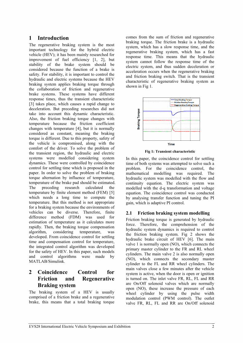
comes from the sum of friction and regenerative braking torque. The friction brake is a hydraulic system, which has a slow response time, and the regenerative braking system, which has a fast response time. This means that the hydraulic system cannot follow the response time of the electric system, and thus sudden deceleration or acceleration occurs when the regenerative braking and friction braking switch. That is the transient characteristic of regenerative braking system as shown in Fig 1.
Fig 1: Transient characteristic
In this paper, the coincidence control for settling time of both systems was attempted to solve such a problem. For the coincidence control, the mathematical modelling was required. The hydraulic system was modelled with the flow and continuity equation. The electric system was modelled with the d-q transformation and voltage equation. The coincidence control was conducted by analysing transfer function and tuning the PI gain, which is adaptive PI control.
2.1 Friction braking system modelling Friction braking torque is generated by hydraulic force. Therefore, the comprehension of the hydraulic system dynamics is required to control the friction braking system. Fig 2 shows the hydraulic brake circuit of HEV [6]. The main valve 1 is normally open (NO), which connects the primary master cylinder to the FR and RL wheel cylinders. The main valve 2 is also normally open (NO), which connects the secondary master cylinder to the FL and RR wheel cylinders. The main valves close a few minutes after the vehicle system is active, when the door is open or ignition is turned on. The inlet valve FR, RL, FL and RR are On/Off solenoid valves which are normally open (NO), these increase the pressure of each wheel cylinder by using the pulse width modulation control (PWM control). The outlet valve FR, RL, FL and RR are On/Off solenoid

EVS28 International Electric Vehicle Symposium and Exhibition 3
valves which are normally closed (NC), decrease the pressure of each wheel cylinder, as well as using PWM control. The pump, which is driven by the electric motor, supplies flow for the hydraulic source to apply pressure inside wheel cylinders. The accumulator stores hydraulic energy when the energy is over sufficient and releases hydraulic energy when the energy is lacking. The pedal stroke simulator simulates the feeling of a driver, because the hydraulic brake circuit of the HEV is isolated with the master cylinder when braking. The hybrid control unit (HCU) calculates demanded friction braking torque by using the regenerative braking algorithm. The PWM modulator controls the inlet valve and the outlet valve to generate friction braking torque
M
Inlet valve FL
Main valve 1Main valve 2
Inlet valve RR Inlet valve RL Inlet valve FR
Outlet valve RL Outlet valve FROutlet valve RROutlet valve FL
Accumulator
Pump Motor
Pedal stroke simulator
Master cylinder
Reservoir
Pedal
Wheel FL Wheel RR Wheel RL Wheel FR
Fig 2: Hydraulic brake circuit of HEV
Fig 3 shows the inlet valve and outlet valve which control the pressure of the wheel cylinder [6]. When controlling the pressure, the inlet and outlet valve complementarily operate at the same time. That is, the inlet valve is open while the outlet valve is close and the inlet valve is close while the outlet valve is open.
Fig 3: Schematic diagram of inlet and outlet valve
Eq. (1) is the flow equation of the wheel cylinder when inlet valve is open.
2( )i v v p w bfQ C A P P (1)
Eq. (2) is the flow equation of the wheel cylinder when outlet valve is open
2( )o v v r w bfQ C A P P (2)
iQ and oQ are respectively the inlet and outlet
flow rate of the wheel cylinder. vC and vA are the
flow coefficient and the valve opening area of the inlet and outlet valve. pP , rP and wP are the
pressure of the pump, reservoir and wheel cylinder.
bf is the density of the brake fluid.
Also the flow rate of wheel cylinder is expressed as Eq. (3), which is the continuity equation.
w w ww
bf
dV V dPQ
dt dt (3)
bf is a bulk modulus of brake fluid and t is
time. wQ and wV is the net flow and the volume of
the wheel cylinder. wV can be obtained by Eq. (4).
2inital
w w wV V r dx (4)
inital
wV is the initial volume of the wheel cylinder,
wr is the radius of the wheel cylinder, and x is the
displacement of the return spring. Eq. (5) represents the relation between hydraulic force and return spring. k is the spring constant.
2w wr dP kdx (5)
With combining Eq. (1), (2), (4) and (5), Eq. (3) can be expressed as Eq. (6).
2 4 2
2v v
bfwinitial
w w w
bf
PC A
dP
r V r dxdt
k
(6)
P can be expressed as p wP P and r wP P when
inlet valve is open and closed.
2.2 Friction braking system control To control the friction braking system, the hydraulic system should be controlled. The state of
EVS28 International Electric Vehicle Symposium and Exhibition 4
the inlet and outlet valve is controlled by PWM control. This generates pressure inside the wheel cylinder by repeating alternately to open each valve with a decided frequency, it is important to measure how long the valve opens in a period; this is defined as the duty ratio which is shown as Eq. (7).
openinlet periodD T T (7)
D is duty ratio, open
inletT is time of opening of the
inlet valve and periodT is a period.
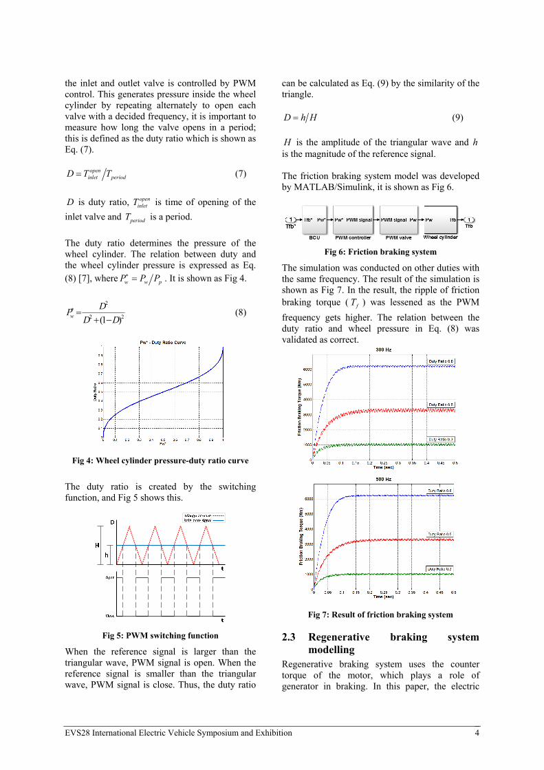
The duty ratio determines the pressure of the wheel cylinder. The relation between duty and the wheel cylinder pressure is expressed as Eq. (8) [7], where w w pP P P . It is shown as Fig 4.
2
2 2(1 )w
DP
D D
(8)
Fig 4: Wheel cylinder pressure-duty ratio curve
The duty ratio is created by the switching function, and Fig 5 shows this.
Fig 5: PWM switching function
When the reference signal is larger than the triangular wave, PWM signal is open. When the reference signal is smaller than the triangular wave, PWM signal is close. Thus, the duty ratio
can be calculated as Eq. (9) by the similarity of the triangle. D h H (9)
H is the amplitude of the triangular wave and h is the magnitude of the reference signal. The friction braking system model was developed by MATLAB/Simulink, it is shown as Fig 6.
Fig 6: Friction braking system
The simulation was conducted on other duties with the same frequency. The result of the simulation is shown as Fig 7. In the result, the ripple of friction braking torque ( fT ) was lessened as the PWM
frequency gets higher. The relation between the duty ratio and wheel pressure in Eq. (8) was validated as correct.
Fig 7: Result of friction braking system
2.3 Regenerative braking system modelling
Regenerative braking system uses the counter torque of the motor, which plays a role of generator in braking. In this paper, the electric

EVS28 International Electric Vehicle Symposium and Exhibition 5
motor is interior permanent magnet synchronous motor (IPMSM). Fig 8 is the schematic diagram of it.
as
bs
cs
S
θN
drqr
Fig 8: Schematic diagram of IPMSM
Kirchhoff's law for a, b and c phases circuit is Eq. (10), (11), (12).
asas as s
dv i R
dt
(10)
bsbs bs s
dv i R
dt
(11)
cscs cs s
dv i R
dt
(12)
asv , bsv and csv are voltage of each phase. asi ,
bsi and csi are current of each phase. sR is phase
resistance. as , bs and cs are linkage flux of
each phase. But the rotator revolves for stator thus as , bs and cs varies on time. To get rid
of time variant inductance, d-q transformation is used. Eq. (13) is the d-q transformation matrix [8].
(13)
Eq. (10), (11) and (12) can be converted into Eq. (14) and (15) by using the transformation matrix which has a rotating d-q coordinate axis with the rotator angular velocity ( r ).
r
r r rdsds ds s r qs
dv i R
dt
(14)
rqsr r r
qs qs s r ds
dv i R
dt
(15)
rdsv and r
qsv are respectively voltage of d and q axis. rdsi and r
qsi are current of d and q axis. rds and r
qs
are linkage flux of d and q axis. These Eq. (14) and (15) can be expressed as equivalent circuit, as shown in Fig 9.
-+
-+
Fig 9: IPMSM equivalent circuit for d-q axis
2.4 Regenerative braking system control
To control regenerative braking system, the electric motor system should be controlled. The IPMSM is controlled by the flux weakening control. This control generates torque by controlling current, so the reference current should be calculated for demanded torque based on maximum torque per ampere (MPTA) control. Torque of IPMSM can be expressed as Eq. (16).
3( )
2 2r r r
m p qs ds qs ds qs
PT i L L i i (16)
p is magnetic flux of permanent magnet. dsL and
qsL are respectively inductance of d and q axis.
In constant torque region, the reference currents are Eq. (17) and (18) [8].
cosrds si i (17)
sinrqs si i (18)
is 2 2 2
18( )
cos4( )i
p p ds qs s
ds qs s
L L i
L L
and si is 2 2ds qsi i .
In constant power region, the reference currents are Eq. (23) and (24) [9].
2 2 22 2 2max
2 2
/ds p ds p qs ds p ds s rrds
qs ds
L L L L L i Vi
L L
(19)
2 2r rqs s dsi i i (20)
maxV is the maximum voltage of motor.
2 2cos cos cos
3 3
2 2 2( ) sin sin sin
3 3 3
1 1 1
2 2 2
T

EVS28 International Electric Vehicle Symposium and Exhibition 6
The torque is controlled by the PI control and it is possible to control the response characteristics by the adaptive PI control for settling time. The finding adequate PI gain for demanded settling time is calculated with transfer function. Fig 10 is the block diagram of the IPMSM control system with PI controller.
Fig 10: Block diagram of IPMSM control system
The block diagram in Fig 10 is expressed as transfer function as Eq. (21) and (22).
* 2( )
( )
rpd idds
drds ds pd s id
K s KiG s
i L s K R s K
(21)
* 2( )
( )
rqs pq iq
qrqs qs pq s iq
i K s KG s
i L s K R s K
(22)
If iK and sR is assumed as ignorant, Eq. (21)
and (22) are approximated to first order transfer function, Eq. (23) and (24).
*( )
rpdds
drds ds pd
KiG s
i L s K
(23)
*( )
rqs pq
qrqs qs pq
i KG s
i L s K
(24)
Eq. (23) and (24) is solved to Eq. (25) and (26).
(L )* (1 )ds pd
t
Kr rds dsi i e (25)
(L )* (1 )qs pq
t
Kr rqs qsi i e (26)
In the first order system, the time constant ( ) indicates the time when the rate of response gets to 63.2% of steady-state. In Eq. (25) and Eq. (26), each time constant is ds pdL K and qs pqL K .
In this paper, time constant was determined depending on settling time. It is the time that reaches the rate of the steady-state between 95%
and 105%. Eq. (25) and (26) are arranged into Eq. (27) and (28) to calculate time constant to satisfy the demanded settling time ( *
st )
*
(L )* *0.95 (1 )s
ds pd
t
Kr rds dsi i e (27)
*
(L )* *0.95 (1 )s
qs pq
t
Kr rqs qsi i e (28)
From Eq. (27) and (28), time constant must be smaller than 0.33 of demanded settling time. Time constant is empirically determined to 1/10 of demanded settling time. This way, the P gains are calculated to Eq. (29) and (30). Then the I gains are empirically calculated.
*
10 dspd
s
LK
t (29)
*
10 qspq
s
LK
t (30)
The regenerative braking system model was developed by MATLAB/Simulink, it is shown as Fig 11.
Fig 11: Regenerative braking system model
The result of the simulation is shown as Fig 12.
Fig 12: Result of regenerative braking system
The simulation was conducted with calculated pK
and iK , to control the settling time, in the same
demanded torque. *mT is normalized torque of
motor. The settling time was 0.0529 sec in 0.05s

EVS28 International Electric Vehicle Symposium and Exhibition 7
control, 0.1032 sec in 0.10s control and 0.1497 sec in 0.15s control. From the result, it was confirmed for settling time to be controllable by adaptive PI control.
2.5 Coincidence control algorithm In this paper, the coincidence control algorithm was proposed to lessen the transient characteristic. This algorithm is shown as Fig 13.
Fig 13: Coincidence control algorithm for friction and regenerative braking system
When braking, the HCU calculates the demanded friction braking torque ( *
frictionT ) and regenerative
braking torque ( *regenerationT ) from the driver’s
brake pedal displacement ( pB ) and vehicle
velocity ( V ). The brake control unit (BCU) converts the demanded friction braking torque into the demanded wheel pressure ( *P ) and sends the response characteristic to the PI gain calculator, where pK and iK gain are calculated
to coincide settling time of both systems. The PWM controller generates the PWM signal to the inlet and outlet valve. The signal determines the state of the PWM valve, open or closed, then generates the pressure ( P ) for the wheel cylinder. As a result, the hydraulic system applies the friction braking torque ( frictionT ) to the wheel.
Meanwhile the motor control unit (MCU) receives the demanded regenerative braking
torque, pK and iK . Then the MCU generates
reference voltage ( *v ) through the inverter. As a result, the motor applies the regenerative braking torque ( regenerationT ) to the wheel. Fig 14 is the
simulation result of the algorithm.
Fig 14: Result of coincidence control
The simulation was conducted during the shifts between the regenerative and friction brakes. Regenerative braking only applied 1000 Nm in 0.8 sec, when regenerative braking was off by the regenerative braking constraint algorithm, then friction braking began to operate to compensate the total braking torque. The friction braking system whose settling time was 0.07992 sec could not meet the total braking torque because it was slower than the regenerative braking system whose settling time was 0.01151 sec. Hence the response characteristic of the regenerative braking system was controlled to coincide the response time. Consequentially, the settling time of the regenerative braking system changed from 0.01151 sec to 0.0817 sec. It was validated that the transient region was improved by using the algorithm.
3 Braking torque compensation control for temperature
The friction braking torque changes with the temperature because the friction coefficient changes with the temperature. This causes the vehicle to be unstable. In this paper, the braking torque compensation control for temperature was attempted to solve the problem. For the compensation control, the braking torque estimator for temperature was needed. Accordingly the temperature estimator for disk brake system was developed. The compensation control was conducted by comparing the demanded braking torque and the estimated braking torque.

EVS28 International Electric Vehicle Symposium and Exhibition 8
3.1 Heat transfer analysis model for disk brake system
In a braking system, various heat transfer phenomena occur, like conduction, convection and radiation. It is difficult to consider all phenomena of the brake components, and thus a simplified heat transfer analysis model is required. Fig 15 is a heat transfer analysis model.
Fig 15: Heat transfer analysis model
In this model, the premise is that radiation is insignificant because it is small compared to the other heat transfer phenomena. When braking system works accordingly, the pad pushes the disk and frictional heat is generated on the surface between the pad and the disk. The portion of the frictional heat that goes through the disk rises the temperature of the disk, and some of it dissipates by convection, the rest of the frictional heat travels to both pads. The frictional heat which goes to the inner pad is conducted to the piston and brake fluid in respectively, which rises the temperature of each component. The heat dissipates on the surface of the brake fluid. The frictional heat, which travels to the outer pad, is conducted from the pad to the caliper, and it dissipates on the surface of the caliper. Fig 16 shows the thermal circuit of the disk brake system [10].
Fig 16: Thermal circuit of disk brake system
3.2 Frictional heat Frictional heat is generated by friction between the disk and the pad. It can be calculated if the braking energy is completely converted into heat energy. The braking energy per unit time is expressed by the result product of friction braking torque ( fbT )
and wheel angular velocity ( w ). That is, the
frictional heat rate ( fq ) is expressed as Eq. (31).
f fb wq T
(31)
The heat is distributed to each disk ( dq ) and pad
( pq ). The distribution of frictional heat helps the
brake system to be simply analysed because the distributed heats to the disk and pad are independent each other. Such distribution factors ( ) can be defined as Eq. (32) and calculated with
a semi-infinite solid heat transfer. Eq. (33) and (34) is the pad and disk temperature equation that uses semi-infinite solid method in constant heat flux [11].
d
p d
q
q q
(32)
2( , )
2
p p pp p
p p
q t xT x t ierfc
k t
(33)
2( , )
2d d d
d dd d
q t xT x t ierfc
k t
(34)
ierfc is integral of the complementary error
function. pT , p and pk are respectively the
temperature, thermal diffusivity and thermal conductivity of the pad. dT , d and dk are
respectively the temperature, thermal diffusivity and thermal conductivity of the disk. On the frictional surface, x is 0 and pT is equal to dT .
Therefore, Eq. (32) can be derived as Eq. (35) [12].
1
1 p p p p
d d d d
A c k
A c k
(35)
p , pc and pA are respectively density, specific
heat and area of pad. d , dc and dA are density,
specific heat and area of disk respectively.

EVS28 International Electric Vehicle Symposium and Exhibition 9
3.3 Finite Difference Method The condition of the braking system changes from moment to moment during driving. This means that the temperature solution should be capable of responding immediately to any circumstance. But it is impossible to get an exact solution because the shapes of the brake components are complex and the heat transfer coefficient changes. FDM, which is a kind of numerical analysis, is effective to solve this complicated problem. FDM approximates and solves the partial differential equation. This method makes a solution for defined discrete points. For a numerical analysis, analysed material should be divided into many sections (dashed square in Fig 17). The reference points that are placed in the middle of the sections are called nodes, this represents the section and its average temperature, and a group of such nodes is called a grid.
Fig 17: FDM grid
In FDM, a partial differential equation is transformed into the difference equation as below. Eq. (36) is an equation to obtain temperature gradient for x direction at ( 1 / 2, )i j . Eq. (37)
is derived to obtain temperature gradient for y direction at ( , 1 / 2)i j . Eq. (38) is derived to
obtain temperature gradient for time ( t ) at ( , )i j [13].
1, ,
1/2,
i j i j
i j
T TT
x x
(36)
, 1 ,
, j 1/2
i j i j
i
T TT
y y
(37)
1
, ,
, j
n ni j i j
i
T TT
t t
(38)
A FDM equation derivation of heat rate, conduction and convection is shown as below. Fig 18 is the FDM grid in the disk brake system.
Fig 18: FDM grid in disk brake system
In heat rate, energy balance method equation is written as Eq. (39). Then, the FDM equation is derived as Eq. (40) by arranging for 3T in Eq. (39).
1
3 32 3( )
2
n nn nx
x
kA T Txq T T cA
x t
(39)
13 2 32 2
2 2 21n n n
x
q t k t k tT T T
cA x c x c x
(40)
k is thermal conductivity, c is specific heat, is
density, xA is area for x direction, x is length for
x direction of cell and t is time step for the FDM. Upper script n
means previous value and
upper script 1n is new value. In conduction, an equation of energy balance method is derived as Eq. (41). Then, the FDM equation is derived as Eq. (42) by arranging from
2T in Eq. (41).
1
2 23 2 1 2( ) ( )
n nn n n nx x
x
kA kA T TT T T T cA x
x x t
(41)
12 1 3 2(1 2 )n n n n
o oT F T T F T (42)
oF is Fourier number, which is 2
t
x
In convection, energy balance method equation is written as Eq. (43). Then, the FDM equation is derived as Eq. (44) by arranging for 1T in Eq. (43).
1
1 12 1 1( ) ( )
2
n nn n nx
x x
kA T TxT T hA T T cA
x t
(43)
11 2 12 ( ) (1 2 2 )n n n
o o oT F T BiT F BiF T (44)
h
is convection coefficient, T
is air temperature,
Bi is the Biot number, which is h x
k
.
With the FDM, the temperature estimation model for the disk brake system was developed using MATLAB/Simulink. It is shown as Fig 19.

EVS28 International Electric Vehicle Symposium and Exhibition 10
Fig 19: Temperature estimator for disk brake system
The brake system temperature estimator was compared with experiment result. It is shown as Fig 20.
Fig 20: Result of brake temperature estimator
In the experiment, the temperature rose early because the thermo-coupler, attached to the pad, was in contact to a frictional surface ahead of braking. The temperature became stable after 4 seconds because its capacity is small. After 4 seconds, the tendency and the value of temperature of both experiment and simulation became similar. It proves that the estimator has credibility based on the results.
3.4 Compensation control algorithm In this paper, the algorithm of braking torque compensation was suggested to control the braking torque which changes depending on temperature. The temperature estimator for the braking system calculates the estimated
temperature ( T̂ ) by using the wheel angular velocity and the friction braking torque. The estimated temperature determines the estimated friction coefficient ( ̂ ) from the temperature-friction coefficient curve. The friction braking torque is estimated considering temperature, then the compensation controller
compares total estimated braking torque ( t̂otalT )
and demanded braking torque ( *totalT ). When
* ˆtotal totalT T , reference friction braking torque is
reduced and when * ˆtotal totalT T , reference friction
braking torque is added. Consequently the compensated braking torque ( **
frictionT ) is
transmitted to the BCU. The algorithm is shown as Fig 21.
BCU
Friction braking system
HCU
MCU
Wheel
Compensation controller
Regenerative braking system
Bp
T**friction T*regeneration
v*P*
Tfriction Tregeneration
Friction braking torque estimator
Temperature-μ curve
Temperature estimator
Vehicle Driver
V
Tfriction
T*friction T*regeneration
^
T^
^μ
Battery
SOC
Fig 21: Braking torque compensation control algorithm for temperature
The simulation result of the compensation algorithm is of Fig 22.
Fig 22: Result of compensation algorithm
The simulation was conducted in time between 5 and 13 seconds in Fig 20. The actual torque was also calculated as plotted in Fig 20. In the result, normal braking system control could not meet

EVS28 International Electric Vehicle Symposium and Exhibition 11
the demanded brake torque but it was confirmed that the braking system, having the compensation algorithm, could expect the demanded braking torque.
4 Integrated control algorithm for coincidence and compensation control
In this paper, the compensation algorithm and coincidence control was combined to improve safety and comfortableness of braking. Reference compensated friction braking torque is sent to BCU. With the braking torque, the HEV brake system is controlled by the coincidence control. The algorithm is shown as Fig 23.
Fig 23: Integrated control algorithm for coincidence and compensation control
The simulation result of the integrated control algorithm was plotted in Fig 24. The simulation was conducted at 120 ℃. The shifts between regenerative and friction braking took place at 0.8 seconds, when there was the transient characteristic. Also an error occured after 0.8 seconds because the friction coefficient was 0.35 at room temperature and 0.4116 at
120 ℃. Such problems were solved by the integrated control algorithm of the coincidence and compensation control.
Fig 24: Result of integrated control algorithm
5 Conclusion For the safety and comfort of the braking system of the HEV, the coincidence control for the friction and regenerative braking system, and the braking torque compensation algorithm for temperature were proposed in this paper. The braking system model and temperature estimator of the HEV were developed using MATLAB/Simulink, then the algorithm was applied. As a result of the compensation algorithm, it was confirmed that the algorithm compensated the demanded braking torque even if the temperature changed. Also, the coincidence control improved the transient region. With the combined algorithms, the safety of the HEV braking system could be impoved. The algorithm is expected to be used for safety of the braking system considering environmental factors.
6 References [1] Hoon Yeo, Sungho Hwang and Hyunsoo Kim,
Regenerative braking algorithm for a hybrid electric vehicle with CVT ratio control, Proceedings of the Institution of Mechanical Engineers, Part D: Journal of Automobile Engineering, 2006, 1589-1600.
[2] Jingang Guo, Junping Wang and Binggang Cao, Regenerative Braking Strategy for Electric Vehicles, IEEE Intelligent Vehicles Symposium, 2009, 864-868.
[3] Jeong Hun Choi, Bae-kyoon Cho, Jinhyun Park, Sung-Ho Hwang, Transient Characteristic Analysis on the Regenerative Braking System of Fuel-cell Electric Vehicle with Electro-Hydraulic Brake, J Korean Soc Fluid Power Constr Equip KSFC, Vol.9, No1, 2012, 1-9.
EVS28 International Electric Vehicle Symposium and Exhibition 12
[4] Jean Greselle Balotin, Patric Daniel Neis, Ney Francisco Ferreira, ANALYSIS OF THE INFLUENCE OF TEMPERATURE ON THE FRICTION COEFFICIENT OF FRICTION MATERIALS, ABCM Symposium Series in Mechatronics, Vol.4, 2010, 898-906.
[5] C.H. Gao, X.Z. Lin, Transient temperature field analysis of a brake in a non-axisymmetric three-dimensional model, Journal of Materials Processing Technology, Vol 129, Issue 1-3, 2002, 513-517.
[6] Junzhi Zhang, Chen Lv, Jinfang Gou and Decong Kong, Cooperative control of regenerative braking and hydraulic braking of an electrified passenger car, Proceedings of the Institution of Mechanical Engineers, part D: Journal of Automobile Engineering, 2012, 1289-1302.
[7] Gang Tao, Min Chen, Tao Zhang, Control Characteristic of PWM Solenoid Valve in the Electro-hydraulic Shift System, IEEE CECNet, 2011, 158-161
[8] Kwang Hee Nam, AC Motor Control and Electric Vehicle Applications, CRC Press, 2010, 42-51.
[9] Sanghoon Kim, DC, AC, BLDC Motor Control Second Edition, BOGDOO, 2010, 395-403.
[10] Kab-Jin Jun, Sung-Pil Jung, Ji-Won Yoon, Yong-Ho Jeon, Tae-Won Park, Jae-Ho Yoon, Numerical Prediction of the Brake Using Friction Heat Division and Conduction, KSAE Fall Conference Proceedings, 2006, 904-909.
[11] H.S.Carslaw and J.C.Jaeger, Conduction of Heat in Solids Second Edition, Oxford, 1959, 75.
[12] Rudolf Limpert, Brake and Design and Safety Second Edition, SAE, 1999, 111-120.
[13] FRANK P. INCROPERA, DAVID P. DEWITT, THEODORE L. BERGMAN, ADRIENNE S. LAVINE, Fundamentals of Heat and Mass Transfer Sixth Edtion, JOHN WILEY & SONS, 2006, 212-215.
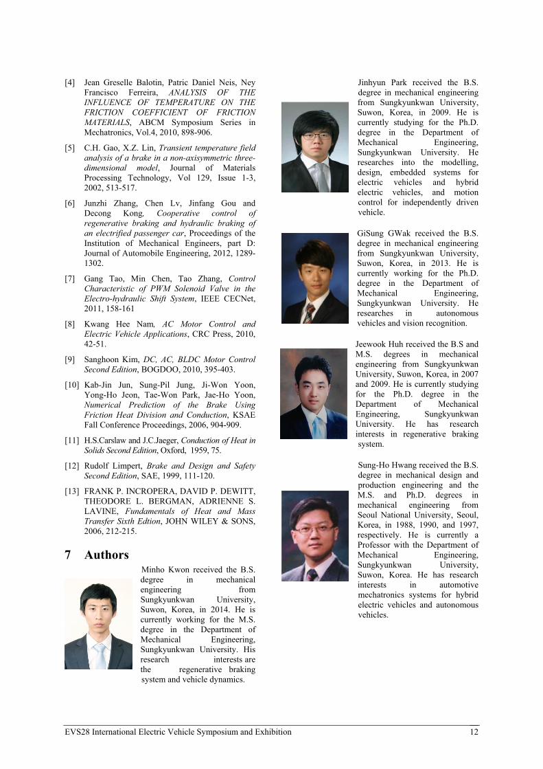
7 Authors Minho Kwon received the B.S. degree in mechanical engineering from Sungkyunkwan University, Suwon, Korea, in 2014. He is currently working for the M.S. degree in the Department of Mechanical Engineering, Sungkyunkwan University. His research interests are the regenerative braking system and vehicle dynamics.
Jinhyun Park received the B.S. degree in mechanical engineering from Sungkyunkwan University, Suwon, Korea, in 2009. He is currently studying for the Ph.D. degree in the Department of Mechanical Engineering, Sungkyunkwan University. He researches into the modelling, design, embedded systems for electric vehicles and hybrid electric vehicles, and motion control for independently driven vehicle.
GiSung GWak received the B.S. degree in mechanical engineering from Sungkyunkwan University, Suwon, Korea, in 2013. He is currently working for the Ph.D. degree in the Department of Mechanical Engineering, Sungkyunkwan University. He researches in autonomous vehicles and vision recognition.
Jeewook Huh received the B.S and M.S. degrees in mechanical engineering from Sungkyunkwan University, Suwon, Korea, in 2007 and 2009. He is currently studying for the Ph.D. degree in the Department of Mechanical Engineering, Sungkyunkwan University. He has research interests in regenerative braking system.
Sung-Ho Hwang received the B.S. degree in mechanical design and production engineering and the M.S. and Ph.D. degrees in mechanical engineering from Seoul National University, Seoul, Korea, in 1988, 1990, and 1997, respectively. He is currently a Professor with the Department of Mechanical Engineering, Sungkyunkwan University, Suwon, Korea. He has research interests in automotive mechatronics systems for hybrid electric vehicles and autonomous vehicles.