Embed Size (px)
Citation preview

Cooling system
表紙
Issued: July 2021
Pub. No. 29Z06-00620
GUIDE TO CAPACITY SELECTIONAND INSTALLATION PLANNING


Cooling system
The major function of cooling system is to maintain the engine components at the correct
temperature under the operating conditions and output range allowed for an engine.
In planning heat recovery, the engine cooling system is the first consideration.
Performance of air-cooled heat transfer equipment greatly depends on ambient air
temperature, humidity, and air flow, and is strongly affected by the installation conditions
and ventilation. Therefore, in planning and designing the cooling system, refer to the related
brochure in this guide.
The cooling system that cannot dissipate all rejected engine heat is hard to correct and
causes over-heating, which, in a worst case, may lead to engine damage. To achieve the
maximum performance and service life, engine must be maintained at correct operating
temperature without overheating or overcooling.


CONTENT
Chapter 1Functions of cooling system
1. Heat rejection....................................1
2. Cooling .............................................12.1 Basic cooling system ....................................1
2.2 Hot part cooling.............................................3
2.3 Lubricating oil cooling ...................................3
2.4 Intake air cooling...........................................3
2.5 Fuel cooling...................................................3
3. Heat rejection and cooling capacity ..43.1 Factor decreasing cooling capacity...............4
3.2 Factor increasing heat rejection....................4
3.3 Capacity of heat transfer equipment .............5
4. Heat balance test..............................64.1 Temperature measuring position ..................6
4.2 Test preparations ..........................................7
4.3 Heat balance test ..........................................8
5. Evaluation of test results...................85.1 Cooling system capacity ...............................8
5.2 Heat dissipation estimation .........................10
5.3 Change after installation .............................10
Chapter 2Heat transfer equipment
1. Radiator ..........................................121.1 Principle ......................................................12
1.2 Structure .....................................................13
2. Heat exchanger ..............................192.1 Heat exchanger rate ...................................19
2.2 Shell and tube type .....................................20
2.3 Plate type ....................................................22
3. Cooling tower..................................243.1 Open-type ...................................................24
3.2 Closed-type.................................................26
Chapter 3Cooling system
1. Radiator cooling..............................271.1 Engine mounted radiator ............................27
1.2 Remote mounted radiator...........................30
2. Cooling tower system .....................332.1 Closed-type closed circuit...........................33
2.2 Open-type closed system ...........................34
3. Direct cooling..................................353.1 Open water tank system.............................36
3.2 Underground water-pool system ................38
3.3 Cooling water management........................39
3.4 Using heat exchanger.................................40
4. Heat recovery system.....................404.1 Heat input to engine ...................................40
4.2 Coolant heat recovery ................................41
4.3 Exhaust heat recovery................................43
5. Other cooling system......................465.1 Radiator and heat recovery ........................46
5.2 System to use water supply source............46
Chapter 4Cooling system failure
1. Corrosion ........................................471.1 Iron corrosion..............................................47
1.2 Risk of stainless steel .................................48
2. Cavitation........................................50
3. Scales.............................................51
4. Deposits..........................................52
5. Salt damage and adhering foreign object ..............................................53
Content - 1

Content
Chapter 5Coolant
1. Water quality...................................541.1 Water property ............................................54
1.2 Water quality standards ..............................56
2. Coolant ...........................................562.1 Antifreeze....................................................56
2.2 Corrosion inhibitor.......................................57
2.3 Coolant preparation ....................................57
Chapter 6Pipe line
1. Flow rate.........................................59
2. Pressure .........................................602.1 Pump outlet.................................................60
2.2 Pump inlet ...................................................60
3. Head loss........................................613.1 Pipe line ......................................................61
3.2 Equipment...................................................65
4. Pump capability ..............................66
5. Design considerations ....................665.1 Pipe line planning........................................66
5.2 Vibration isolation........................................68
5.3 Heat insulation ............................................68
5.4 Service convenience...................................69
Content - 2
Chapter 1 Functions of cooling system
1. Heat rejectionIn general, supposing that heat input into engine, that is, low heat value of fuel is 100%, motive energy extracted from crankshaft is 35 to 45%, and the remaining 55 to 65% input energy is rejected as heat. Burning energy at combustion stroke is extracted as power through piston. Meanwhile, pressure and heat which was not used effectively are rejected together with exhaust gas during exhaust stroke.
Heat generated by combustion is transferred to piston, cylinder liner, and cylinder head that constitute a combustion chamber.
Frictional heat created between moving parts in engine such as cylinder liners and pistons, shafts and bearings, cams and cam followers, and gears is mainly transferred to lubricating oil.
Heat is dissipated to ambient air by radiation from high-temperature cylinder head and exhaust manifold and conduction from cylinder block surface heated via the jacket water coolant and lubricating oil.
Heat that was rejected to lubricating oil by piston cooling and conduction from cylinder liners and bearings is transferred from oil cooler mounted on engine to jacket water coolant.
Compression by turbocharger raises intake-air temperature. In general, compressed intake air is cooled by an aftercooler using jacket water coolant, and heat absorbed from the intake air is rejected to the coolant.
For engines aiming for higher power and/or minimal exhaust emissions, intercoolers are used. Intercooler uses more low-temperature coolant from a separate cooling system to cool intake air.
Amount of heat rejected to jacket water coolant is, in general, 20 to 30% of total heat input at engine rated output. Coolant must be cooled through heat transfer equipment to be maintained at a constant temperature, because it receives heat rejected from engine.
The approximate amount of heat rejected to exhaust is 30%, and the heat is dissipated to the atmosphere together with exhaust gas through the exhaust system.
Heat that was transferred from the exhaust system surface to the ambient air by radiation and conduction is removed through ventilation, if required.
The amount of heat radiated from engine surface to the ambient air is about 5%, and the heat should be removed properly by ventilation system.
For more details of the amount of heat rejected to engine coolant, exhaust, and ambient air, refer to your MHIET dealer.
2. Cooling
2.1 Basic cooling systemEngine jacket water coolant flows through engine, aftercooler and oil cooler mounted on engine, to receive heat from them, and then moves to a radiator placed near the engine. Radiator is heat exchanger most commonly used for heat dissipation of engine coolant, and in general, it is cooled by pressure-supplied air flow from engine driven fan (See Fig. 1-1).
For marine and cogeneration (combined heat and power) engines equipped with water cooled exhaust manifold, part of heat in exhaust gas is transferred to jacket water coolant.
1
Chapter 1 Functions of cooling system
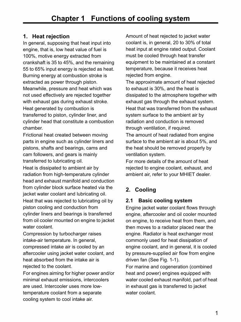
Fig. 1-1 Basic configuration of cooling system
Jacket water pump is generally a centrifugal type, and its outlet pushes coolant to engine inside.
While coolant temperature is low, temperature regulators (thermostats) close the engine coolant outlet so that the coolant flows through a bypass.
When coolant temperature reaches the valve opening temperature, the thermostats open the coolant outlet so that the coolant flows into a radiator. As the temperature gets higher, the coolant passage is widely opened so that more coolant flows into the radiator, and thereby the coolant temperature in engine is maintained at a constant level.
After the thermostats fully is opened, the maximum coolant temperature stays at the equilibrium point between the engine heat rejection and the capacity of heat transfer equipment.
In the vicinity of the valve opening temperature of thermostat, opening valve may decrease coolant temperature, and thereby close and open the valve repeatedly, which may lead to fluctuation in coolant temperature, flow, and pressure (hunting).
Hunting tends to occur particularly in the cooling systems having multiple thermostats. For those systems, the difference of around 5°C in valve opening temperature should be set between the thermostats.
For the MHIET engines, the two-step opening thermostats may be used to avoid the combination of the thermostats in which the same valve opening temperature is set.
Radiator
Thermostat
Aftercooler
Oil cooler Cylinder block
Jacket water pump
Bypass
Cylinder head
Fan
2

Chapter 1 Functions of cooling system
2.2 Hot part coolingGenerally, coolant is pushed into an engine by engine-driven jacket water pump. The coolant flows through the water passages (jacket) in cylinder block and head, absorbing heat from the surrounding walls, and then moves to a radiator.
Jacket water coolant not only directly cools down hot parts such as cylinder liners and heads in the engine by removing heat from them, but also indirectly cools down piston rings, valves, valve seats, valve guides or spark plugs through the cooled down portions.
Combustion chamber components are exposed to high temperature.
They must be maintained at proper temperatures to keep the design clearances between moving parts as well as to guarantee long service life.
Extremely high temperature not only shortens the service life of parts but also damages them. Thus, even if coolant temperature is within appropriate range, engine exhaust temperature should be measured to check for abnormal combustion.
2.3 Lubricating oil coolingLubricating oil that reaches high temperature due to heat from bearings and cylinder liners and piston cooling must be cooled by passing through oil cooler. Oil cooler is the heat exchanger for engine oil and coolant. Heat is transferred from lubricating oil to low-temperature jacket water coolant. Since engine coolant is maintained at a proper temperature with the thermostats, lubricating oil also has the constant temperature level.
2.4 Intake air coolingCompression by turbocharger raises air temperature and reduces the air density (oxygen). In most high-powered engine, high-density supply air is supercharged into cylinders by cooling the air with cooler.
The most conventional diesel engines are equipped with aftercoolers using engine coolant. On the other hand, intercoolers which use more low-temperature coolant obtained by heat transfer equipment in the separate cooling system were adopted mainly for marine diesel engines and gas engines.
Nowadays, supply air temperature needs to be lowered in diesel engine by tighter emission regulations. Therefore, air-to-air heat exchanger which uses ambient air to cool supply air like radiator is used.
Air-to-air coolers require never-heated fresh air. Thus, they must be arranged closer to radiator fan or should be located beside radiator side by side.
2.5 Fuel coolingFuel injection pump compresses fuel to high pressure. Therefore, the temperature of the fuel injection pump rises due to compression heat of air in the fuel, friction heat of moving parts, and thermal conduction from cylinder block.
In general, injection pump is cooled by supplied fuel, and fuel absorbs heat and is injected for combustion. And, extra fuel transferred for cooling absorbs heat and is returned to fuel tank, where the fuel is cooled.
3
Chapter 1 Functions of cooling system
The temperature of fuel supplied from fuel tank or fuel at injection pump inlet may exceed the specified level, depending on the size and installation conditions of the fuel tank. In this case, remote mounted fuel cooler is required.
3. Heat rejection and cooling capacity
3.1 Factor decreasing cooling capacity
The factors which dominate the capacity of heat transfer equipment are discussed in the Chapter 2 "Heat Transfer Equipment".
The factors that reduce the heat dissipation capability of the heat transfer equipment in operation are as follows.
3.1.1 Contamination
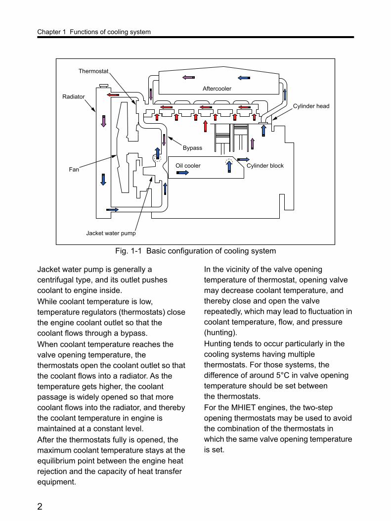
Internal contamination.Scales and deposits have lower thermal conductivity than heat transfer surfaces. Especially, the scales deposited on the internal surface of heat exchanger core degrade heat transfer to decrease heat exchanger rate.External contamination.Outdoor air sucked in by radiator for heat dissipation contains foreign objects such as floating dust and insects. The foreign objects adhere to fins in passing through the radiator or stay and stick in front of the fins, thereby decreasing the radiator heat dissipation capability.Leak of engine oil, fuel, or coolant in the engine-driven unit accelerates adhesion of foreign objects, thereby decreasing heat dissipation capability early.
3.1.2 Resistance
Internal Resistance.Deposits on the tubes and plates of heat transfer equipment's core narrow small passage especially in plate-type heat exchanger. Then, coolant flow rate decreases due to increased flow resistance, and thereby heat exchanger rate is reduced.External Resistance.Foreign objects adhered to radiator core or air inlet and packing materials of cooling tower may decrease air flow to reduce heat dissipation capability.
3.1.3 Strong wind
Strong wind will roll back discharge air from the outlet of radiator duct and remote mounted radiator to reduce fan performance, thereby decreasing heat dissipation.
When strong wind hits remote mounted radiator or cooling tower, the hot air or high humidity air discharged from the outlet can return through the inlet opening (recirculation). This recirculation phenomenon will decrease heat dissipation capability. Discharged air recirculation tends to occur particularly in the multiple remote mounted radiators or cooling towers arranged close to each other.
In practice, it may be hard to predict the occurrence of the above events and their impact on heat dissipation capability in use of heat transfer equipment before installing engine-driven unit and cooling system.
3.2 Factor increasing heat rejectionAn amount of heat generated by engine varies depending on its operating conditions.
4

Chapter 1 Functions of cooling system
MHIET provides the heat rejection data including tolerances. However, the factors below may change heat rejection in use. The factors are related to normal deterioration allowed in engine until next maintenance or part exchange and maintenance quality.
3.2.1 Air quantity
Even within the permissible limit, clogged air cleaner gradually increases its resistance, thereby decreasing engine air intake volume.
Contamination in turbocharger compressor wheel or air cooler decreases supercharging pressure or increases supply air temperature, thereby decreasing weight of air charged into cylinder. Decrease in the charged air inhibits fuel burning, which leads to engine power reduction. Governor increases fuel injection quantity in order to increase engine output, which causes incomplete combustion for more excess fuel to decrease combustion efficiency further.
3.2.2 Fuel quantity
Combustion products deposited on injection nozzle hole disturb fuel splay to cause incomplete combustion, thereby decreasing engine output.
Slight wear of needle valve, valve seat, or pressure-adjusting spring reduces valve opening pressure to change fuel spray flow, thereby decreasing combustion efficiency.
And, piston rings and cylinder liners are gradually worn out between major overhauls, which increases combustion blow-by leaked to crankcase to decrease combustion efficiency.
3.2.3 Ignition timing
Detonation (knocking) may be caused in gas engines by several factors.
When detected knocking exceeds the permissible limit, ignition timing will be retarded automatically, and thereby engine efficiency and output decrease.
In diesel engine, difference of injection timing decreases combustion efficiency, thereby increasing fuel injection quantity.
Even if exhaust emission produced by the above phenomenon is within the allowable range of emission regulations and engine operation, burning fuel increases. And also, amount of heat rejected to coolant and exhaust gas will increase in proportion to fuel consumption.
3.3 Capacity of heat transfer equipment
Cooling system must dissipate all the heat rejected from engine when the engine produce maximum power under the permissible highest ambient temperature and altitude.
Capacity of heat transfer equipment and heat rejected from engine may vary depending on various factors in operation. To maintain steady engine operation, therefore, the capacity of heat transfer equipment must be at least 110% of the standard heat rejected from engine.
The lowest limit of the capacity required for the heat transfer equipment of engine coolant is 110% of the heat rejected to jacket water coolant. It includes heat rejected to coolant from engine oil cooler and aftercooler.
5

Chapter 1 Functions of cooling system
Gas engine is equipped with intercoolers which have circuit separated from jacket cooling system and cools down supply air or fuel-air mixture before supercharging it.
In general, cooling tower is used to obtain coolant of 32°C or lower required for intercoolers. The cooling tower capacity must be 110% of the heat rejected through an intercooler.
Turbocharged diesel engine which meets the tight emission regulation uses the air-to-air cooler to cool supply air.
When air cooler is arranged in front of a radiator, heat rejected from the air coolers is transferred to air that enters the radiator. Therefore, in determining the radiator capacity, the heat must be taken into account. When air cooler is positioned beside the radiator, the air quantity for cooling purpose must be included in the ventilation air volume of package or engine room.
4. Heat balance testCoolant temperature rises until the equilibrium between the amount of heat rejected from engine and the amount of heat dissipated from the cooling system is reached. In other word, coolant temperature rises until temperature difference between coolant and heat medium becomes constant. This means the heat transfer equipment must have enough capacity to transfer all the heat absorbed from engine by coolant to other medium.
When external cooling system is combined with engine for the first time, the heat balance test must be performed to evaluate temperature under the actual equilibrium condition.
4.1 Temperature measuring position
As shown in Fig. 1-2, basically, the temperature of air and coolant should be measured to evaluate heat balance.
Fig. 1-2 Temperature measuring position
TG2 TG1
T0
TE1
TE2
TR1
TR2
6

Chapter 1 Functions of cooling system
4.2 Test preparationsLubricating oil must be filled to the specified level of oil gauge.
4.2.1 Use of the fresh water
Fresh water (tap water) shall be used in heat balance test for the reasons described below:
Ultimate heat dissipation capability in cooling system can be achieved by using fresh water.Glycol has lower thermal conductivity than water. Coolant temperature difference (temperature difference between maximum coolant temperature and
ambient air temperature) increases by 1°C per 10% antifreeze concentration. In other word, smaller coolant temperature difference shows the cooling system has higher heat dissipation capability.Preparation for possible changes or equipment relocations based on test results.If heat balance problem occurs, coolant may have to be drained for equipment disassembly/reassembly.When the test takes place at the manufacture location of engine-driven unit, the coolant will be drained in order to reduce the unit weight in transportation.If the mixture of fresh water and antifreeze is used as coolant in testing, it must be disposed of as hazardous waste according to the appropriate regulations.
4.2.2 Filling capability
Cooling system must be fully filled with fresh water. Then, the time required to fill a radiator must be measured.
The radiator must be filled as quickly as possible with hoses or measuring containers. However, be careful so that water does not overflow from radiator filler. The filling speed of 10 liters/min for the SB, SA, and SR series engines, or 20 liters/min for the SU series will be satisfactory.
4.2.3 Air venting capability
Prior to the heat balance test, the air venting capability of the cooling system must be evaluated by following the procedures below.
Start an engine without the radiator cap. After no-load low-speed warm-up operation, raise the speed to the rated one.
[ T0: Ambient temperature ] Outdoor air temperature in the vicinity of the ventilation air inlet at engine room or package and sufficiently distanced from generator.[ TG1: Air temperature at generator air inlet ]Intake air temperature at cooling air inlet located in the generator rear end.[ TG2: Air temperature at the generator air outlet ]Discharge air temperature at cooling air outlet located in the generator front end.[ TE1: Coolant temperature at engine outlet ]Temperature of the coolant between the engine thermostat outlet and radiator inlet.[ TE2: Coolant temperature at engine inlet ]Temperature of the coolant between the radiator outlet and engine inlet.[ TR1: Air temperature at radiator inlet ]Temperature of the air between the engine front end and radiator; the average value of the values measured at several points is desirable. [ TR2: Air temperature at radiator outlet ]Temperature of the air discharged from the radiator front surface; the average value of the values measured at several points is desirable.
7

Chapter 1 Functions of cooling system
Operate the engine under loaded condition. When the coolant temperature at engine outlet exceeds the thermostat valve opening temperature, releases the load. Run the engine at the low speed to cool down it, and then stop the engine.Wait for the engine to cool down to the temperature before operation, and then add water to full level in the radiator.The volume of added water corresponds to the volume of the air which remains in the system in initial filling. If it is within approximately 10% of total volume that the entire cooling system holds, the air venting capability is acceptable.
4.2.4 Thermostat
In the heat balance test, the thermostat must be fully opened and the bypass circuit must be closed with the following reason:
The water flow at engine outlet is certainly kept to maximum.When the thermostat valve opening malfunctions with some reason, it cannot be always detected in the heat balance test. Therefore, the modified test thermostat which is mechanically fully opened must be assembled into an engine.
4.2.5 Preparations for measurements
Prior to starting an engine, thermometers or thermo sensors must be fixed to each measuring position.
Thermometers must not be placed every measurement. Otherwise, the rotating portion of engine-driven unit may cause a danger to human body and thermometer reading error.
Any objects around the unit must be removed or fixed. Otherwise, they may be sucked into fan and damage radiator.
For safety, put a cover on the rotating portion and power generation circuit at the engine-driven unit or arrange barriers around them to prevent the people from coming close to them.
4.3 Heat balance testIn the heat balance test, basically, the temperature of each specified position of engine-driven unit should be measured with 25%, 50%, 75% and 100% rated output (load) respectively.
When engine load is changed, it takes some time to reach the temperature equilibrium between the engine and external cooling system. Normally, the test should be started from 25% load. In each load, approximately 20 minute operation is required to stabilize the engine load. After temperature stabilization at each measuring position is confirmed, record the thermometer's temperature reading at all measuring positions. And, in order to ensure that enough time to stabilize temperature was taken at each load, the temperature reading time should be also recorded.
Note: When the heat balance test is performed for industrial vehicles or construction machines, the coolant circuit in cab heaters must be closed at engine outlet.
5. Evaluation of test results
5.1 Cooling system capacityThe maximum coolant temperature at engine outlet in the heat balance test is the equilibrium temperature between the heat rejection and cooling capability in the test.
8

Chapter 1 Functions of cooling system
The capability of the engine cooling system based on the test conditions can be expressed by ∆T (Coolant temperature difference) as follows:
In the actual operation, the permissible highest ambient temperature must be obtained using the following formula:
Temperature T is the permissible highest ambient temperature when engine coolant reaches its permissible highest temperature.
For MHIET medium/large sized engines, the permissible coolant temperature at engine outlet is basically 98°C.
Example:
When the coolant temperature at engine outlet is 85°C and the ambient temperature is 30°C in the test, then the coolant temperature difference ∆T is 55°C. From there, T = 98 – 55 = 43.
In this example, the permissible ambient temperature is 43°C, on condition that the engine and cooling system are under the same condition as the heat balance test.
When the allowable ambient temperature is lower than the highest ambient temperature estimated at the installation site of engine-driven unit, there is something wrong with either heat
rejection or dissipation.
In the generator set with an enclosure, outside air that entered air inlet is heated while the air flows near engine and generator. So, the intake air temperature is usually increased about 10°C by the time when it reaches a radiator. When an enclosure is to be mounted after the heat balance test, this temperature increase must be considered.
The MHIET engines are equipped with the switches (electrical contact) which open and close to notify the protection and warning device when coolant temperature reaches the warning or limiting level. When the coolant temperature reaches the warning level, the appropriate measures must be taken to prevent the temperature from increasing further. When the coolant temperature reaches the limit level, the protection and warning device must control an engine to stop it.
The standard air temperature at generator inlet is 40°C.
When the cooling air temperature of generator exceeds the standard maximum temperature of 40°C, the generator power output will be restricted. Therefore, in generator set with an enclosure, the package intake air inlet and ventilation air flow must be considered to supply freshair to the generator.
The air temperature at generator outlet is normally higher than
the inlet temperature by a few degrees.
ΔT = Coolant temperature difference (°C)
TE1 = Coolant temperature at engine outlet (°C)
T0 = Ambient air temperature (°C)
Where:ΔT = TE1 - T0
T = TEmax - ΔTWhere:
TEmax = Permissible highest coolant temperature at engine outlet (°C)
T = Permissible maximum ambient temperature increase (°C)
(hereinafter, TG1)
(hereinafter, TG2)
9

Chapter 1 Functions of cooling system
Guide vanes for discharge air, if necessary, should be provided in the generator to prevent engine air cleaner from sucking in discharged air directly.
5.2 Heat dissipation estimationHeat rejected from engine can be calculated by the following formula:
When the radiator airflow volume is known by measurement, the estimate heat dissipation can be obtained by the following formula:
Heat amount rejected from generator can be obtained, in the same manner as radiator, by multiplying the temperature difference of by the generator cooling air volume.
Heat dissipated from engine to ambient air can be estimated from the temperature difference between TG2 and TR1 and the air flow volume that passes through radiator.
5.3 Change after installationIdeally, the test conditions should be consistent with the environment in which engine-driven unit and its attachments are installed actually. From practical standpoint, however, the test maynot cover some conditions.
The coolant temperature at engine outlet may vary due to the difference between the test conditions and on-site installation environment.
Ambient air temperature around engine-driven unit in the on-site operation.The heat dissipation capability of radiator is proportional to the temperature difference between coolant and air. Thus, when the actual air temperature is lower than that in the test, the coolant temperature at engine outlet is decreased, or vice versa.And, engine combustion is affected by intake air temperature. Then, the engine heat rejection may slightly vary.Installation arrangement, ventilation, and air flow.Duct resistance or wind blowing against discharge air outlet creates pressure to decrease the heat dissipation capability of radiator in comparison with testing.Ventilation air volume and air flow in engine room significantly affect the temperature of air drawn into radiator.Part of ambient air drawn by radiator fan is sucked in by generator to cool windings. After absorbing heat from windings, the air is discharged from the generator air outlet on the engine side. Thus, ventilation air flow affects also the engine intake air temperature.
Cp : Specific heat of water (kJ/kg°C)γ : Water density (kg/L)V : Coolant flow volume (L/min)
Where:Qe = ( TE1 - TE2 ) x V · γ · Cp
Qe : Engine heat rejection rate (kJ/min)
γ : Air density (kg/m3)Ar : Radiator air flow rate (m3/min)
TR1 : Air temperature at radiator inlet (°C)
TR2 : Air temperature at radiator outlet (°C)
Qr : Radiator heat dissipation rate (kJ/min)
Where:Qr = ( TR2 - TR1 ) x Ar · γ · Cp
Cp : Specific heat of air (kJ/kg°C)
(TG2 - TG1)
10

Chapter 1 Functions of cooling system
Concentration of anti-freeze added to coolant for actual use.At least 30% anti-freeze must be mixed with the coolant in the engine cooling system. The coolant temperature at engine outlet is estimated to be increased by at least 3°C in comparison with the heat balance test.Ratio of actual load to rated output.When actual load is less than the rated output, the temperature difference between coolant inlet and outlet is decreased proportionally to the ratio of actual load to rated output. Then, when thermostats are fully opened, the coolant temperature will decrease by decreased temperature difference.
Nevertheless, before putting the engine-driven unit installed on the site into operation, the heat balance test should be performed to reconfirm the temperature at the specified positions under the actual conditions.
In addition, when the ambient temperature on the test day is different from the highest or lowest temperature anticipated at the site, the measured data must be corrected by adding or subtracting the temperature difference to reconfirm that there is nothing wrong.
11
Chapter 2 Heat transfer equipment
Cooling system uses radiator, heat exchanger, and cooling tower mainly either in standalone mode or with their combination.
Heat removed from engine is finally dissipated into air or recovered to be reused. This section describes heat transfer equipment that has the common function to transfer the heat to other heat media through coolant.
1. RadiatorRadiator is the heat exchanger of coolant and air used in engine-driven unit that evolved mainly in the automobile industry.
In the open-type cooling system, coolant is exposed to the atmosphere, and the closed-type uses radiator.
1.1 PrincipleCoolant flows downward perpendicularly in the radiator tubes, and air passes horizontally along many fins around the tubes.
In general, the radiator cooling air is pressure-supplied by fan driven with engine or electrical motor.
For the radiator used in generator set, only blower type fan is applied mainly with generator cooling taken into consideration.
Radiator shape is mostly rectangular with manufacturing reasons. Meanwhile, the airflow area of fan is circular because the fan rotates. The radiator with the push type fan which pushes air toward the radiator tends to have low cooling capacity in comparison with the suction type.
In the case of automobiles, the suction type fan which distributes airflow in the opposite direction from vehicle is popular.
Vehicle go forwards much more frequency than it goes back and higher speed and engine power are required for going forward. Therefore, the radiator is placed in the front end to utilize relative airflow by the driving speed of vehicle actively.
12

Chapter 2 Heat transfer equipment
1.2 Structure
1.2.1 Body
Fig. 2-1 shows the typical radiator.
Fig. 2-1 Basic structure of radiator
Coolant flows into the top tank shown in the left Figure, goes downward through water tubes, and then is collected at the bottom tank.
Coolant flows downwards in the tubes by pump, as low-temperature coolant descends with its increasing density.
Solid water expands its volume by 4.3% when temperature rises from 0°C to 100°C.
The coolant in engine, piping, and radiator expands and contracts with temperature change between engine stop and operation.
The top tank must have enough free volume to cover at least 5% expansion of the total coolant in the cooling system in addition to full water level in cold condition (See Fig. 2-2).
Fig. 2-2 Conceptual drawing of radiator top tank
Pressure cap
Reserve tankShroud
Core
Coolant inlet
Coolant outlet
Tubes
Top tank
Bottom tank
Dog house Coolant inletPressure cap
Vent hole
Tube
Reserve:
Expansion volume: 5%Filler
Lowercoolant
100%Minimumvolume
Low coolant
Full levelin cold condition
13

Chapter 2 Heat transfer equipment
The inlet of top tank should always be placed under the low water level so that the coolant from the inlet may not involve air and vapor in the top tank space.
In addition, it is desirable to arrange guide vanes or chamber called dog house in the inlet end to rectify flow.
The coolant level may be reduced at short times due to consumption such as evaporation or slight leakage in engine operation. The coolant between the inlet port and the full level in cold condition is the reserve volume for compensating for the consumption.
In order to extend maintenance interval, coolant in the full level in cold condition should include 5% reserve coolant.
Coolant from the inlet, flowing in a lateral direction at the top tank, goes downward into tubes.
To separate air bubbles in flow in lateral direction, top tank section (thickness in front/rear direction) should be designed so that the coolant velocity can be 0.6 m/sec or lower.
For the total volume of the top tank including reserve and minimum coolant volume in addition to expansion space volume, approx. 20% of coolant volume in the whole engine cooling system is required.
The filler neck which connects coolant filling port and top tank inside must have a vent hole near the tank top. The function of the hole is to vent air accumulated in the upper part at the top tank in filling coolant and to induce gas separated from coolant in operation toward the pressure cap.
Top tank coolant level must be always higher than the highest level in engine (mainly, thermostat housing). This should be accomplished in the radiator design and arrangement for engine.
Coolant which dissipated heat in flowing down in tubes is collected in the bottom tank at the lowest position of radiator and returns to engine.
In order to distribute coolant flow in tubes uniformly, the bottom tank coolant outlet should be placed on the diagonal line to the coolant inlet (the opposite side from width).
1.2.2 Pressure cap
Pressure cap maintains pressure in radiator above the atmospheric pressure by sealing the radiator to raise the coolant boiling point, which prevents vapor production in the engine high-temperature portion and negative pressure at the water pump inlet side.
There are two types of pressure cap. One type has only a pressure regulating valve (pressure valve) to maintain positive pressure in radiator within the set range. The other type has both pressure and vacuum valves for reserve tank.
The vacuum valve assembled in the pressure cap for reserve tank opens and forms a passage between the reserve tank and top tank when negative pressure in radiator becomes lower than the set value.
As shown in the Fig. 2-3, when pressure in radiator is stable in cold condition, the two valves are closed and the cap is sealed up.
14

Chapter 2 Heat transfer equipment
Fig. 2-3 Configuration of pressure cap
Fig. 2-4 State of overflowing to reserve tank
When radiator cannot hold coolant expansion volume and pressure in the top tank exceeds the set value at engine running, as shown in Fig. 2-4, the pressure valve opens to move overflow coolant into a reserve tank through a hose.
After engine stops, coolant temperature gradually goes down. When pressure in top tank falls below the set value with coolant shrinkage, the vacuum valve opens and atmospheric pressure applied to the reserve tank moves coolant to the top tank.
Coolant continues to move until pressure in radiator reaches the set value of vacuum valve. (See Fig. 2-5)
Fig. 2-5 State of returning to reserve tank
Coolant reciprocation between radiator and reserve tank depends on the difference between the internal pressure in radiator and the atmospheric pressure applied to the reserve tank. Therefore, when the reserve tank is arranged in the position lower than the top tank and in the case described below, caution is required.
Note: If air leak occurs at the radiator pressure cap or the end connection or hose between coolant filler neck and reserve tank, coolant may leak outsides or not return from reserve tank to radiator.When this failure is overlooked, even if the reserve tank is full, the radiator coolant decreases, which may cause engine overheat and, in the worst case, damage the engine.MHIET recommends checking the radiator pressure leak and inspecting the pressure cap at periodic maintenance.
Filler neck
Pressure valveVacuum valve
Connecting portto reserve tank
Must open up to the atmosphere
15

Chapter 2 Heat transfer equipment
1.2.3 Reserve tank
Reserve tank holds extra coolant for radiator, and when it is made of plastic or has sight glass, it can be used to monitor coolant level visually from outside easily and replenish coolant easily and safely.
In the radiator whose top tank does not have sufficient volume, the reserve tank may be used to receive coolant expansion volume overflowed from the tank.
Expanded coolant moves from the top tank to the reserve tank, and shrunk coolant returns from the reserve tank to the top tank when the pressure in radiator gets negative.
If there is air in the top tank, the air is discharged to the reserve tank together with coolant when the coolant and air expand.
As the radiator temperature goes down, inside coolant and residual air shrink. Then, coolant which corresponds to air discharged in expanding returns to the top tank, and thereby air in the top tank decreases.
When a little air is left in the top tank, it is discharged completely by repetition of engine running and stop.
However, when much air is left, the air expands with coolant shrinkage, and the radiator pressure is kept positive, therefore, the coolant may not return to the top tank.
If engine coolant does not overflow from the reserve tank even at its highest temperature and does not fall below the lower limit of coolant level at the tank in cold condition, the cooling system expansion volume is held in the tank, and the coolant left in the reserve tank in the cold condition is just the extra volume.
The radiator which has extra coolant in the reserve tank can be always filled with coolant regardless of inside temperature. Therefore, as pressure is applied to coolant by the pressure cap even when engine stops, pressure resistance must be considered.
The sum of the top tank free volume and the reserve tank capacity should be 10% of the coolant volume in the whole cooling system. In other words, the radiator top tank should hold the minimum coolant volume and the reserve tank should hold the reserve coolant volume and expansion volume.
Note that there are two different methods of managing coolant level in reserve tank.
One is to maintain the highest level or lower at engine running and the lowest level or higher at engine stop in cold condition.
Note that, if the tank is filled with coolant up to the highest level in cold condition, it overflows from the reserve tank at engine running.
The other is to maintain the coolant level between the lowest and highest ones at engine stop in cold condition. Do not confuse the two methods.
1.2.4 Core
There are two shapes for the fins which compose the radiator core.
16

Chapter 2 Heat transfer equipment
[Corrugated fin type]
The fins of this type are made by folding like wave thin plates with high thermal conductivity such as copper, aluminum and its alloy. Tubes are formed in cylindrical shape using the same kind of materials.
Corrugated fins are attached as if the tubes lined up between top tank and bottom tank were connected (See Fig. 2-6).
Fig. 2-6 Corrugated fin
Since the corrugated fins have larger fin surface per unit area in the radiator frontal area compared with the plate fin type. Therefore, the corrugated fins tend to have higher heat dissipation capacity in comparison with the plate fin type with the same frontal area.
The plate fins are joined with the frames at the both sides of radiator to form tubes and grid. Meanwhile, the corrugated fins are put between tubes and supported by them. Therefore, the corrugated fins tend to be inferior in the mechanical and thermal strength of the entire radiator in comparison with the plate fin type.
[Plate fin type]
Plate fins are the flat ones made by punching out thin plate, and tubes are inserted and lined up in holes (See Fig. 2-7).
Fig. 2-7 Plate fin
Plate fins tend to have lower heat dissipation capacity and higher strength in comparison with corrugated fin type with the same frontal area.
Since the plate fin pitch is large in comparison with the corrugated fin type, foreign objects are unlikely to be deposited between the fins. Therefore, the plate fin type tends to be used in the radiators in severe environment such as construction machines and industrial vehicles.
For the MHIET generator set, the plate fin type is applied to particularly the radiators for which countermeasure against salt damage is required.
Tubes
Colgated fins
Air flow
Coolant flow
Air flow
Tubes
Plate fins
Coolant flow
17

Chapter 2 Heat transfer equipment
1.2.5 Cooling capacity
The heat amount which radiator can dissipate into air i.e. the cooling capacity is determined by the factors below.
Water equivalent.Coefficient determined by the volume and velocity of the coolant flowing through the core tubes.Air equivalent.Coefficient determined by the volume and velocity of the air flowing around the fins.Radiation area.Surface area of the fins and tubes contacting air.
Coolant temperature difference.Logarithm mean temperature difference between the coolant and air flowing into the fin area.Blade tip clearance.Clearance between the radiator shroud and fan blade tip.Overlap.Length by which the width of the fan blade tip overlaps the shroud depth.
In addition to the factors described above, the distance between the fan front and core surface affects the fan performance (See Fig. 2-8).
Fig. 2-8 Arrangement of fan and radiator
When radiator is fixed and engine is supported by vibration isolator, clearance must be provided between the fan blade tips and shroud bore. Otherwise, the tips may move with engine vibration or fluctuation to contact with the shroud bore. Smaller blade tip clearance can increase the fan efficiency.
In the case of the push type fan, the fan blades should be inserted into the shroud by 30% to 50% of the fan blade width as overlap for the metallic fan, and 20% to 40% for the resin fan. About 10% of the fan diameter is required for the distance between the fan front and core surface. When customers or OEMs prepare radiators, MHIET recommend purchasing them from reliable makers..
Shroud
Fan
Tip clearanceOverlap
Front distanceFan diameter
18

Chapter 2 Heat transfer equipment
2. Heat exchangerThis section describes the jacket water coolant to the cooling water (not necessarily solid water), i.e., the liquid-to-liquid heat exchanger such as shell and tube type and plate type.
2.1 Heat exchanger rateThe heat exchanger rate of the heat exchanger is determined by the following.
The logarithm mean temperature difference is calculated by the next formula, with reference to the countercurrent flow, based on the temperature difference between the high-temperature side (coolant) and low-temperature side (cooling water) at the heat exchanger inlet and outlet(Because, in the case of the countercurrent flow, the temperature of the outlet in the high-temperature side can be lower than that of the outlet in the low-temperature side).
Substitute the numerical formula with the temperature difference between the high temperature and low temperature sides.
For the heat exchangers, there are two types of usage.
One is the "concurrent flow" in which the flow directions are common to the high-temperature side and low temperature-side, and the other is the "countercurrent flow" in which the flow directions are opposite each other.
If other conditions are omitted, the heat exchanger rate is proportional to the logarithm mean temperature difference. Therefore, the two types are compared by obtaining the temperature difference between the both flows.
Where: Q: Heat exchanger rate
Δt: Temperature change of liquid to be cooled
Where: A: Surface area of wall separating high and low temperature sides
Cp: Specific heat of liquid to be cooled
V: Liquid flow volume to be cooled
U: Overall heat transfer coefficient of heat exchanger
Q = V · Cp · Δt
Q = A · U · Δtim
Δtim: logarithm mean temperature difference (LMTD)
Inlet temperature
Outlet temperature
High-temperature side tHinLow-temperature side tLout
tHout
tLin
(tHout - tLin)(tHin - tLout)
Inlet temperature
Outlet temperature
Δtim = (tHin - tLout) - (tHout - tLin)
ln
Δtim = Δin - Δout
ln ΔinΔout
Δin = tHin - tLoutWhere:
Δout = tHout - tLin
19

Chapter 2 Heat transfer equipment
According to the result of the above calculation, the logarithm mean temperature difference in the "countercurrent flow" is small as compared with the "concurrent flow".
And, the high-temperature side can be cooled to the same temperature by coolant in the low-temperature side whose temperature is higher than that of the "concurrent flow". Therefore, it is understood that the cooling capacity of the "countercurrent flow" is higher.
2.2 Shell and tube typeShell and tube type heat exchanger has the structure in which narrow tubes are lined up in parallel in cylindrical shell.
Heat transfers from engine coolant flowing outside the tubes inside the shell (high-temperature side) to cooling water flowing inside the tubes (low-temperature side).
This type is classified into the one-pass type in which liquid flows in one direction in the low-temperature side (See Fig. 2-9) and the two-pass type in which liquid reciprocates by turn (See Fig. 2-10). In these types, flow in the high-temperature side is controlled by changing the arrangement and number of baffles in the shell variously.
2.2.1 Single-pass type
In the single-pass type heat exchanger, liquid in the low temperature side in tubes flows in only one direction.
In general, in the single-pass type heat exchanger, the "countercurrent flow" in which liquid in the high-temperature side flows in the opposite direction from the low-temperature side is adopted, because the heat exchanger rate is larger than the "concurrent flow" (See Fig. 2-9).
[Countercurrent flow] Inlet temperature
Low-temperature side90 °C
48°C 38°C82°C
82
38
Δout
90
48
Δin(tHin - tLout)
Δin = 90 - 48 = 42 (°C)Δout = 82 - 38 = 44 (°C)
42 - 44ln
Δtim =
4442
= 43.0 ( °C)
Outlet temperature
Inlet temperature
Outlet temperature
High-temperature side
High-temperature sideLow-temperature side
[Concurrent flow]Outlet temperature
Inlet temperature
90 °C 82°C
40°C30 °C
82°
40° (tHout - tLout)Δout
Δin(tHin - tLin)
90°
30°
Δin = 90 - 30 = 60 (°C)Δout = 82 - 40 = 42 (°C)
60 - 42
lnΔtim =
4260
= 50.5 (°C)
20

Chapter 2 Heat transfer equipment
Fig. 2-9 Single-pass type shell and tube heat exchanger
2.2.2 Multiple-pass type
As shown in Fig. 2-10, in the multiple-pass type heat exchanger, liquid in the low-temperature side goes and returns.
Fig. 2-10 Multiple-pass type shell and tube heat exchanger
2.2.3 Features
The shell and tube type heat exchanger is relatively robust. Therefore, it is mounted on the common bed of engine or engine-driven units and is used to cool engine jacket coolant, engine oil, fuel, and lubricating oil of power transmission equipment.
Its heat transfer area is wide for volume and it is relatively inexpensive. However, the installation area tends to be wider than the plate type.
And, in general, the outer surface on tubes is difficult to clean due to its structure.
Jacket coolant inlet Set of tubes
Jacket coolant outlet
Cooling water outlet
Cooling water inlet
Buffles
Shell
Jacket coolant inlet
Cooling water inlet
Cooling water outlet
Jacket coolant outlet
Buffles
21

Chapter 2 Heat transfer equipment
2.3 Plate type
2.3.1 Structure
In the core of the plate type heat exchanger, thin plates with concaves and convexes (emboss pressed) are piled up (See Fig. 2-11).
Fig. 2-11 Configuration of plate type heat exchanger
Thick plate frames are located at the front and the rear of the heat exchanger. Flanges for piping in the high-temperature side (e.g. engine jacket coolant) and low-temperature side (e.g. cooling water) are connected through the four holes in the front frame.
The rear frame can be moved back and forth through the guide bar, and the plates are press-stacked to the front frame by the hardware.
Basically, the plate shapes are classified into two types, and the liquid in eitherhigh-temperature side or low-temperature side flows (See Fig. 2-12).
Fig. 2-12 Plate configuration
The heat transfer surface of the plate is formed with concaves and convexes for liquid diffusion and collection and expansion of surface area. The plate surface is separated from the passagesfor the other liquid by the gasket which contains its inlet and outlet ports.
The plates in the high-temperature side and low-temperature side are piled up by turns, thereby forming the passage for coolant between the plates (See Fig. 2-13).
Frame Plates
Inlet/Outletports
FrameGuide bars
[Low-temperature side plate]
Inlet port oflow-temperatureside
Outlet port oflow-temperatureside
Inlet passage forhigh-temperatureside
Outlet passage forhigh-temperature side
Gasket
Plate
Inlet passage forlow-temperature side
Inlet port ofhigh-temperature side
[High-temperature side plate]
Outlet passage forlow-temperature side
Outlet port ofhigh-temperature side
22

Chapter 2 Heat transfer equipment
Fig. 2-13 Coolant passage between plates
The ports of the inlet and outlet surrounded by the gasket forms the passage for liquid when the plates are piled (See Fig. 2-14).
Fig. 2-14 Flow inside each plate
Liquid of low-temperature side (Cooling water)
Liquid of high-temperature side (Engine coolant)
Backmost plate
Inlet ofhigh-temperature side
Foremost plate
Outlet oflow-temperature side
Outlet ofhigh-temperature side
Inlet oflow-temperature side
23

Chapter 2 Heat transfer equipment
Coolant flows out of the inlet hole in the high-temperature side, diffuses over the heat transfer surface of the plate flowing downward, and then is collected to the outlet hole.
Coolant flows similarly along the next plate in the high-temperature side separated from one plate in the low temperature side, and after entering the outlet hole, flows through the passage toward the front side of the heat exchanger.
Cooling water flows upward from the inlet port located under the plate in the low-temperature side, flows through the outlet port, and then gathers in the front side of the heat exchanger.
The first plate facing the front frame is solely used for liquid passage, and the last plate facing the rear frame does not have a hole and stops liquid flow.
Generally, the plate type heat exchanger also maximizes the heat exchanger rate by the countercurrent flow.
2.3.2 Feature
The installation area is small as compared with the shell and tube type with the same heat exchanger rate. In addition, the heat exchanger rate can be changed by increasing and decreasing the number of the plates.
The plates are easy to clean, because the whole exchanger can be easily disassembled. On the other hand, since the gasket deteriorates, it needs to be exchanged periodically.
3. Cooling towerThe largest advantage of cooling tower is to decrease the coolant temperature to the level which cannot be achieved by the
radiator cooling. Depending on the use conditions of cooling tower, 32°C or lower coolant required for the intercooler with the separated cooling circuit can be provided.
The heat dissipation from cooling tower mostly depends on the phenomenon in which water takes away heat required for evaporation (vaporization heat) from contacting object. Therefore, under the environment of 100% humidity, coolant temperature can be a little decreased.
In other words, heat dissipation depends on the wet-bulb temperature (humidity) of ambient air, and coolant temperature cannot be lower than the wet-bulb temperature.
According to Japan Cooling Tower Institute, the standard capacity of cooling tower is defined in the inlet air wet-bulb temperature of 27°C in the inlet water temperature of 37°C and outlet water temperature of 32°C.
In the cooling tower used in hot water system in cold regions, the protection measures such as heater installation and permanent hot water circulation must be taken. Otherwise, cooling water in the cooling tower or circuit may freeze during engine stop.
Cooling tower is classified into two types: Open-type in which cooling water is exposed to outdoor air and closed-type in which cooling water is cooled in the closed circuit.
3.1 Open-type
3.1.1 Structure
Fig. 2-15 shows the two types of the open-type cooling tower.
24

Chapter 2 Heat transfer equipment
Fig. 2-15 Open-type cooling tower
In the countercurrent flow type shown in the left Figure, hot water dropped from the upper part of the cooling tower hits upward air flowing from the lower part.
The surface of the water droplets that directly contact the air evaporates, when heat is removed from the remaining part of the droplets and the temperature of dropping hot water decreases.
The part of the hot water heat is transferred to the air.
For the cross-flow type shown in the right Figure, ambient air around the cooling tower enters the tower, flows transversely, and gets out of the upper part.
In the cooling tower in the Figure, packing materials are used to increase the contact area and time of hot water and ambient air. Hot water drops down from upper portion and permeates into the packing materials.
The surface of the hot water evaporates in the course of passing through the packing materials, when vaporization heat is removed from the remaining water and then the temperature of the hot water decreases.
Cooled hot water becomes cold water and gathers in the pan at the tower bottom, and returns to the original place through piping from the cold water outlet.
3.1.2 Feature
The features are as follows because of direct cooling by air:
The efficiency (cooling capacity) is higher than the closed-type with the same dimension.Due to contact with outdoor air, foreign objects such as floating dust and fungi suspended in the atmosphere may invade into cooling water (hot/cold).Condensation and accumulation of foreign objects accompanying evaporation are unavoidable.Therefore, dilution of condensed water and discharge of deposit by continuous blow-down of cooling water (drain and replenish) are required.
[Cross-flow type]
Hot water
Cooled water
[Countercurrent flow type]
Discharge air
Cooled water
Packing material
Hot water
Ambient air
Ambient air
Discharge air
Ambient air
Ambient air
25

Chapter 2 Heat transfer equipment
For the engine cooling system, in principle, the open-type cooling tower must not be used in standalone mode. If it has to be used unavoidably, it must be connected through a heat exchanger, and the engine cooling system must be a closed circuit.
3.2 Closed-type
3.2.1 Structure
In the closed-type, water is supplied in droplets from the upper part of the tower to
piping and removes heat from the piping with vaporization heat and heat transfer, by which hot water passing through the piping is cooled indirectly.
It is classified into the countercurrent flow type and the cross-flow type, based on the relations between the flows of cooling water and air.
Fig. 2-16 shows the closed-type cooling towers.
Fig. 2-16 Closed-type cooling tower
The left Figure shows the countercurrent flow type, and the right one shows the cross-flow type using packing materials.
In general, this type of cooling tower is equipped with an expansion tank.
When using the closed-type cooling tower for the engine cooling system, mix coolant with antifreeze.
3.2.2 Feature
This type has the following advantages and disadvantages compared with the open-type.
Since it is shut off from outdoor air, neither mixing of foreign objects nor condensation occurs. Therefore, the ingredients of cooling water do not change.Because of inefficiency due to indirect cooling, dimension about twice as large as the open-type with the same capacity is required.
[Countercurrent flow type] [Cross-flow type]
Hot water
Discharge airAsperison
Packingmaterial
Feed water
Discharge air
Feed water
Hot water
Cooled water
Ambient air
Recovery and recirculation
Cooled water
Ambient airAmbient air
Recovery and recirculation
Ambient air
26

Chapter 3 Cooling system
1. Radiator coolingThe cooling system using radiator is the engine outlet control type. Coolant volume which flows into radiator and dissipates heat is controlled by the thermostat to maintain the lowest temperature of engine.
1.1 Engine mounted radiatorIn this type of radiator cooling system, the radiator is mounted in front of an engine and cooling air is pushed by fan driven by the engine (See Fig. 3-1).
Fig. 3-1 Cooling system with engine mounted radiator
In this type, the cooling system piping is the shortest and coolant volume is also the minimum. In other words, the cost required for jacket water treatment and additives is the most inexpensive, which is the advantage of this type. Therefore, this type is the standard closed-type cooling system of engine-driven unit.
1.1.1 Basic configuration
Radiator is closely mounted in front of the engine which is placed on the foundation or common bed. Especially when vibration isolators are arranged under the common bed, radiator must have enough vibration strength, because vibration is transmitted from engine to radiator through the common bed.
If radiator is fixed and engine is supported with vibration isolation under the mounting feet, fan must not contact radiator shroud because of vibration in engine running or
large engine movement in its start and stop.
Flexible pipe joints such as hoses are required for the connection between the radiator and engine coolant outlet/inlet.
For those joints, not only sufficient flexibility but also enough strength and heat resistance to withstand the positive pressure and temperature of coolant are required. In addition, enough strength to resist negative pressure created at the suction side of jacket water pump is required.
For the models which cool the intake air after turbocharger by air cooling with radiator (PTAA/TAA), the expansion joint with flanges bolted at both ends may be installed between the engine pipes of intake air. In case of such models, assembling and adjustment of radiator piping must be completed before removing bolts of expansion joint. If the bolts are
Discharge air
GeneratorEngine
Engine mountedradiator Coolant inlet
Coolant outlet
27

Chapter 3 Cooling system
removed first before piping, the excessive local stress on the joint which lead to breakage may occur.
1.1.2 Filling and venting
Stand-alone radiator has the requirement such as heat dissipation. Meanwhile, in combination with engine, enough speed to fill up with coolant is required. Approximately filling speed of 10 liter/min for middle-sized engine or 20 liter/min for large-sized engine is required.
Air in radiator and engine must be vented smoothly with coolant filling. In the cooling system of which venting capability is insufficient, coolant replenishment and engine running must be repeated alternately to purge air. And, it is possible that air remains in the system.
Air venting capability is evaluated with following procedures.
Fill up with coolant initially and start engine. After no-load low-speed warm-up operation with the radiator pressure cap removed, raise the speed to the rated one. When the thermostat valve opening temperature is exceeded, run the engine at the low speed to cool down it, and then stop the engine.When the engine cools down to the temperature before operation, replenish the same coolant to full level in the radiator.The volume of added coolant corresponds to the volume of the air which remains in the system in initial filling. If it is within approximately 10% of total coolant volume that the entire cooling system holds, the air venting capability is acceptable.
1.1.3 Fan
In the generator set, radiator is always mounted in front of engine, and the blower type fan in which air is supplied from the engine side toward the radiator must be used.
The worldwide standard of the temperature at the cooling air inlet of generator is 40°C at maximum. Otherwise, the generator power output will be restricted. Therefore, fresh air must be supplied from outdoors to the cooling air inlet of the generator.
Even if engine overheat occurs, never try to increase the fan speed to solve the problem.
The centrifugal force acting on rotating body is proportional to square of rotational speed.
Therefore, if the fan speed is increased by 20%, then the centrifugal force is increased 1.44 times, and the fan blade may not withstand the centrifugal force to be broken and scattered.
In addition, the engine power consumed by fan is proportional to cube of rotational speed. Therefore, in the case above, the required fan horsepower increases 1.73 times, which might cause larger fuel consumption or power shortage in engine.
1.1.4 Ducting
Air pushed by fan reaches a high temperature by receiving heat from the core when it passes through radiator, and is discharged forward.
When an engine-driven unit is installed indoors, hot air from radiator must be discharged to outdoors through a duct (See Fig. 3-2).
28

Chapter 3 Cooling system
Fig. 3-2 Radiator duct
If air from radiator outlet is discharged in the engine room, there is a high possibility of causing engine overheat problem or large expense to facilities which meet enormous ventilation air volume requirement.
Duct and discharge air outlet have to meet the requirements below.
Duct must be made of flexible materials such as sailcloth or have its structure which can isolate the thermal expansion and vibration of radiator.When less flexible materials such as steel plate are used, movable duct connection is required at the radiator duct flange part.Note that the engine-driven unit mounted on vibration isolators may be greatly fluctuated in its start and stop.Duct that lacks flexibility transmits vibration and noise from engine around the outlet hole.Air must not leak in duct in order to prevent indoor temperature rise and noise transmission.
Duct should be as short as possible. However, enough distance required for radiator mounting/dismounting or major overhaul of the engine front must be kept.Duct should be easy to disassemble if needed.For the discharge air outlet penetrating the building wall, some measures to prevent large foreign objects from invading into duct from outside must be taken.In addition, the discharged air outlet should be placed so that it can avoid prevailing wind direction such as sea breeze/land breeze and wind blowing through buildings.Wind which blows from outside to duct outlet obstructs air discharge, reduces the radiator heat dissipation capability, and in the worst case, might cause engine overheat.Install louvers for wind protection at the discharged air outlet with the following taken into consideration.Moveable louvers must be always opened in engine running.
EngineGenerator
Discharge air
Louvers
Duct
Duct flange
29

Chapter 3 Cooling system
The movable louvers using discharge pressure of radiator fan may not operate due to their freeze or corrosion, depending on the installation environment. Their mechanism should use motive energy such as electricity, air pressure, and oil pressure. And, their opening and closing should be controlled with radiator coolant temperature or engine room temperature.
The opening area of duct and discharge air outlet must meet the following requirements.
Inner dimensions of duct must not be smaller than those of core part at the connection in the radiator side.When MHIET supplies radiator and engine, they must be equipped with the standard duct flange on delivery if requested.When wire mesh or louvers are attached at the discharge air outlet, their aperture ratios (ratio of air passage area to the entire inlet area) must be used to estimate the effective outlet area. And, in calculating the outlet dimensions, air flow resistance large compared with a simple hole must be taken into consideration. In addition, when a hood is attached at the outlet, pressure loss created by turning of air flow must be added to the air flow resistance.
When a wall is set outside the air discharge outlet for wind protection or sound insulation, the distance between the outlet and wall should be more than twice as large as the fan diameter, in order to reduce local resistance created by direction change of air flow.
Anyway, air flow resistance applied to the fan front must be within 50 Pa (5 mm H2O).
1.2 Remote mounted radiatorThe engine mounted radiator may not be adopted, depending on the installation or operating conditions. The radiator may be difficult to mount on the common bed for engine-driven unit due to the limits on vibration proof, dimensions, weight, and piping. Or, the radiator may not be able to be installed indoors due to the discharge air processing or restrictions on the installation. In these cases, remote mounted radiator is used.
Then, the upright type should be used.
When an ordinary radiator is mounted horizontally, the top tank will not operate and gas in coolant will not be separated. Also for the remote mounted radiator, the coolant in which antifreeze and corrosion inhibitor are added to solid water must be used.
1.2.1 Standard arrangement
This system, which circulates coolant with a jacket water pump, must meet the following requirements (See Fig. 3-3).
30

Chapter 3 Cooling system
Fig. 3-3 Remote mounted radiator cooling system
Capability of jacket water pump. The piping head loss (resistance) created by the coolant flow rate required to transfer engine heat rejection must not exceed the permissible external resistance in the pump.The static pressure created by the head between the center of jacket water pump and the inlet of remote mounted radiator must not exceed the permissible value of 0.1 MPa at the pump inlet (Head of 1 m creates pressure difference of 0.01 MPa).
For the capability of jacket water pump, refer to the MHIET dealer.
The radiator or expansion tank must be equipped with a vent cap or pressure cap to make the closed cooling system.
The coolant level in the remote mounted radiator or expansion tank applies static pressure to the engine cooling circuit. Therefore, in general, when the radiator is installed much higher than the engine (the head exceeds the valve opening pressure of pressure cap), the pressure cap is not required.
In addition, note that the valve opening pressure of the cap is applied to the static head on the inlet of jacket water pump.
Piping route.The horizontal piping from the engine-driven unit to the remote mounted radiator must always have upward slope without ups and downs which may create air trap.In addition, in the routing, the horizontal and vertical piping length should be minimal and the number of bending should be as small as possible.Expansion volume.The top tank of the remote mounted radiator must have enough volume to cover the expansion volume of coolant in the entire system consisting of the radiator and piping. Otherwise, an expansion tank must be installed higher than the highest coolant level in the radiator.
Remote mounted radiator
Engine
Static head
Jacketwater
pump
31

Chapter 3 Cooling system
1.2.2 Installation for excessive head
Installation methods for high head should be studied under the following conditions.
When resistance in the piping created by required flow rate of coolant exceeds the permissible external resistance of jacket water pump.When water head between the pump center and the inlet of the remote mounted radiator exceeds 0.1 MPa.
In any case, a boost pump must not be connected with an engine jacket water pump in series.
Excessive head water pressure over the permissible pressure at the inlet of jacket water pump must not be applied to the jacket water pump in any case. Otherwise, water may leak from the pump.
A decompression tank can be arranged between the engine and the remote mounted radiator to reduce the head from high place (See Fig. 3-4).
Fig. 3-4 Remote mounted radiator at high place
Install the decompression tank within the range which meets the standard arrangement conditions, and pump up coolant to the remote mounted radiator by a circulating pump.
When the circulating pump stops after engine running is finished, the coolant at position higher than the decompression
tank returns to the tank. Therefore, the decompression tank must have enough capacity to cover not only the total amount of coolant supplied to the radiator and piping located above the tank but also reserve volume corresponding to 10% of the total coolant volume.
EngineJacket waterpump
Decompressiontank
Vent cap
Circulating pump
Remote mounted radiator
Head
32

Chapter 3 Cooling system
Decompression tank must be equipped with a vent cap because the inside space volume changes as coolant moves.
Decompression tank must be not equipped with a pressure cap, because the cap's valve opening pressure is added to the head between the decompression tank and engine jacket water pump.
The remote mounted radiator should be equipped with a sealed pressure cap with vacuum valve. The cap prevents coolant overflow caused by pressure created in passing through the radiator,and puts outside air in the radiator when coolant drops into the decompression tank.
Circulating pump must be started before engine starts. Otherwise, hot coolant may get into the radiator abruptly to cause heat shock problem.
In addition, the circulating pump must be stopped after no-load cool-down running to lower the cooling system temperature uniformly.
2. Cooling tower systemThe features of this system are generally used for gas engine intercoolers with separated cooling circuit.
There are two types in the cooling tower: Open-type in which cooling water is exposed to outdoor air and closed-type in which cooling water is cooled in the closed circuit.
Whichever cooling tower is used, the closed-type cooling system and coolant must be used for engine.
2.1 Closed-type closed circuitFig. 3-5 shows the cooling system for intercooler with separated circuit using the closed-type cooling tower.
Fig. 3-5 Closed circuit with closed-type cooling tower
Intercooler
Engine
Circulating pump
Closed-typecooling tower(with expansion tank)
Hot water
Coldwater
3-way valve
33

Chapter 3 Cooling system
Coolant is circulated between the intercooler and cooling tower by the circulating pump installed in the engine side.
The closed-type cooling tower must be equipped with an expansion tank to compensate for coolant expansion and contraction by temperature change.
Water vapor contained in supplied air is saturated and condensed while it is cooled in the intercooler.
When intake air with temperature of 28°C and humidity of 100% is compressed by turbocharger and is cooled to 33°C through an intercooler, precipitate of approximately 900 cc per minute is formed at engine output of 1000 kW. Therefore, a drainage mechanism may be required in the air intake side in the humid environment.
2.2 Open-type closed systemDue to contact with outdoor air, foreign objects such as floating dust and fungi suspended in the atmosphere may invade into cooling water. In order to avoid failure of cooling system caused by condensation of the objects due to evaporation, blow-down with electrical conductivity ofcoolant or periodical blow-down of cooling water is required.
This type of cooling tower in which coolant use is difficult cannot be applied to the engine cooling system with the circuit opened.
In order to seal up the cooling system in the engine side, a heat exchanger must be installed between the engine and cooling tower (See Fig. 3-6).
Fig. 3-6 Closed cooling system with open-type cooling tower
Primary coolant between the engine and heat exchanger is circulated by a jacket water pump.
Secondary cooling water between the cooling tower and heat exchanger is circulated by an electrical pump.
Open-typecooling tower
Circulating pump
Engine
Expansion tank
Vent pipe
Heat exchanger
Hot water
Cold water
Jacket waterpump
34
Chapter 3 Cooling system
The expansion tank equipped with a sealed pressure cap must be installed at the highest position in the engine cooling system.
The total volume of the expansion tank should be at least 15% of the total coolant amount held in engine, heat exchanger, and piping. Expansion volume must be at least 5% of the total coolant amount in the system.
When piping has downward slope from the engine coolant outlet to the heat exchanger, a vent pipe must be connected between the highest point of the pipe line and the expansion tank.
MHIET does not recommend using well water for cooling water at cooling tower, because well water generally has high hardness and is liable to form scales inside heat exchangers and piping. MHIET recommends using soft water which complies with the MHIET water quality standards as cooling water.
Cooling tower cools by vaporization heat of water. Therefore, cooling water always has to continue to evaporate, and ingredients contained in supplied water are left and condensed in the cooling system.
Even if cooling water supplied initially is soft water, its hardness increases by condensation while it is used in the cooling tower, which causes problems in the secondary side of the cooling system.
In addition, note that corrosion might be caused in the secondary cooling system by acid rain.
In order to control condensation, automatic continuous blow-down equipment which discharges and replenishes cooling water when required, monitoring electrical conductivity of water must be arranged.
Further, depending on water quality, agents preventing scale and rust may have to be added to the cooling water.
The cooling tower installed in the place where the ambient temperature falls below freezing point has to be equipped with the heater to prevent cooling water from freezing during engine stop.
For the cooling water treatment and freeze prevention, refer to cooling tower manufacturers or water processing specialists.
3. Direct coolingThis simple system cools engine directly with solid water without using heat transfer equipment.
In direct cooling, users must always recognize not only unavoidable corrosion in the cooling system but also the possibility that potential problems such as pitting and clogging may actually occur in corroded piping and intercoolers.
In addition, note that MHIET does not recommend this system. In this system, cooling water does not flow through intercooler until engine warms up and thermostat opens. And, due to airshortage caused by taking in hot air without cooling it, engine emits black smoke considerably, which may cause environment problems.
MHIET does not recommend using stainless steel, even if customers request.
Stainless steel shows strong corrosion resistance depending on use conditions, material types, or treatment. However, when it is used in the external cooling systems of engine, it involves taking risks.
35

Chapter 3 Cooling system
Engine is generally made of iron. If piping and a water tank are made of stainless steel, the connection with engine must be insulated electrically completely. Otherwise, bimetallic corrosion will occur.
In addition, when foreign objects are deposited on the surface of stainless steel, crevice corrosion may develop into pitting corrosion, thereby causing severe damages.
Therefore, the direct cooling system should be applied limitedly only to the standby generator set under any of the following conditions.
Radiator, heat exchanger, or cooling tower is not available.
Generator set with radiator cooling system cannot be adopted due to the limitation of installation site and facilities such as renewal of existing set and capacity increase.Standby generator set in the place where the possibility that power shutdown may occur due to the breakdown of heat transfer equipment or circulating pump cannot be eliminated completely.Customers understand the corrosion and other problems of the cooling system, and users maintain and manage the cooling system and cooling water properly to minimize corrosion.
3.1 Open water tank systemFig. 3-7 shows the basic structure of the open water tank system.
Fig. 3-7 Basic structure for open water tank system
Generally, tap water is used for cooling water. And, an open water tank is used for the following reasons.
A tap and engine must not be connected directly according to Water Supply Act in Japan.
Jacket water pump
Cooling water outlet
Feed water
Level of low water flow alarm
Open water tank
Cooling water inlet
Vent pipe
Discharged water
50mm
EngineThermostat
Head
Pump head
Check valve is not recommended
36

Chapter 3 Cooling system
Cooling water may have to be released into atmospheric pressure in order to prevent head from a water tank at high location or outlet pressure directly applied to engine by a circulating pump.In installing the cooling system of open water tank system, the following requirements must be met.
3.1.1 Open water tank
The lowest water level must be always higher than thermostat housing in order to prevent air from coming into cooling water inside engine.
The highest water level in the tank must be controlled by float valve, etc. attached to the feed water inlet to prevent cooling water from overflowing.
Air to fill the upper space of the tank must be supplied from opening at the upper part or a vent pipe in order to prevent the water level variation from fluctuating pressure inside the tank.
3.1.2 Piping at outlet of engine
cooling water
The piping must have upward slope to its highest position. For siphon prevention, the highest position must be about 50 mm higher than the maximum water level in the open water tank, and a vent pipe must be connected from the piping top to the tank space.
Head between the jacket water pump and the piping top must not exceed 0.1 MPa, which is the maximum allowable pressure applied to the pump inlet.
3.1.3 Vent pipe
Air coming out from engine in running must be discharged to the open water tank. And, aeration from the upper part of the open water tank must prevent siphon phenomenon which is caused by negative pressure created at the cooling water outlet piping after engine stops.
In engine running, the flow rate of cooling water into the open water tank through vent pipe must be adjusted by valve opening degree.
Note: MHIET does not using check valve for siphon prevention (as siphon breaker).Check valve puts ambient air in the piping to prevent siphon phenomenon. However, the mechanism of check valve does not leak anything out of the piping. Therefore, gas cannot be discharged from the engine or the piping at the cooling water outlet.Gas inside engine reduces the discharging performance of jacket water pump, and in the worst case, the water pump runs idle (rotates without water).For overheat prevention, the piping must be equipped with the low water flow alarm device that operates with the lowest water level of the open water tank and the suspension of water circulation inside engine.
37

Chapter 3 Cooling system
3.2 Underground water-pool system
This system circulates cooling water between large-volume underground water-pool and engine (See Fig. 3-8).
Fig. 3-8 Underground water-pool system
Negative pressure cannot be applied to the suction side of engine jacket water pump, i.e. head cannot be held. Therefore, cooling water must be supplied from the underground water-pool to the open water tank by electric circulating pump.
For operation in power failure, the power source of standby generator set must be used for the motor which drives the circulating pump.
The open water tank must be arranged to prevent the circulating pump from applying the maximum discharge pressure to the suction side of the jacket water pump.
Otherwise, the jacket water pump must be removed from engine and water must be supplied directly from the circulation pump to the inlet of the engine cooling water.
The pressure created at the circulating pump when the thermostat is closed must not exceed the engine pressure resistance.
The measures for the protection of the cooling system such as strainer at the inlet side of the circulating pump must be taken in order not to send the cooling system solid foreign objects together with cooling water.
Discharged water
Circulating pump
Open water tank
Engine
Underground water-pool
38

Chapter 3 Cooling system
3.3 Cooling water managementNote that, if water in the tank installed in high place or underground water-pool is not replaced for a long time, stored water may be condensed, deteriorated, or altered.
Depending on the tank structure, foreign objects or living things from ambient air may invade into the tank to form deposits inside the cooling system. In addition, when the installation site is close to main highways or factories, components contained in exhaust gas from vehicle or boilers may deteriorate water quality.
For any type of water tank, water must be analyzed periodically, and, if it does not meet MHIET's water quality standard, it must be replaced.
The inner surface of water tank or open water tank may get corroded to form red rust in the cooling system. Water in the tank released to atmosphere may get much oxygen in dissolving to early corrode particularly near the water surface at the tank. Therefore, the water tank mustbe checked periodically and repair of antirust treatment such as coating is required for inner surface.
Since ordinary paint membranes are porous and permeate water, they cannot prevent corrosion for a long period. Depending on customers, the water tank with standard coating may be used and be exchanged after corrosion progresses, or the tank with costly special surface treatment may be adopted.
Note that internal corrosion may lead to pitting on the cooling water piping.
In the direct cooling system, while the generator set stops, space without water may be created inside engine and piping to cause and promote corrosion at the air/water boundary. Overall corrosion will reduce the thickness of pipe wall and makes pits somewhere. Local pitting corrosion under the debris of foreign rust will penetrate at this point.
Aside from the engine with thick wall (corrosion margin), for thin piping and supply air coolers, the time required for pitting varies depending on the water quality and management.
Cooling water inside engine must be replaced periodically.
In the test operation of standby generator set, if no-load operation continues or the set stops before a thermostat is opened sufficiently, cooling water stays in engine and is not replaced with feed water.
Condensed and deteriorated cooling water, deposited red rust, and solid foreign objects should be removed from engine. Therefore, water inside the engine should be exchanged by opening the thermostat fully in the periodic load running or discharging water from the cylinder block.
Especially, deposits inside cooler may not only obstruct cooling water flow and heat exchange to raise the temperature of supply air and exhaust air but also develop foreign rust into pitting corrosion, thereby pitting cooler early.
39

Chapter 3 Cooling system
3.4 Using heat exchangerThe sealed pressure type in which a heat exchanger is added between the feed-water system and engine system is
excellent engine cooling system because the features of simple direct coolingsystem are maintained (See Fig. 3-9).
Fig. 3-9 Tap water cooling via heat exchanger
If the flow required for heat exchanger is obtained by head between the open water tank and the inlet of engine cooling water, no circulating pump is required at the outlet of the open water tank.
The expansion tank equipped with a sealed pressure cap must be installed at the highest position in the engine cooling system.
The total volume of the expansion tank should be at least 15% of the total coolant amount held in the engine, heat exchanger, and piping. Expansion volume must be at least 5% of the total coolant amount in the system.
4. Heat recovery systemIn response to the needs of effective energy use and CO2 emission control, the cogeneration (combined heat and power) type generator set which can use not only electrical power but also heat energy effectively is being generalized.
The heat recovery type cooling system that recovers and reuses heat rejected from engine is installed.
4.1 Heat input to engineHeat input, i.e. the heat energy supplied to engine is the low heat value (LHV) of the fuel consumed by engine in a unit time.
Circulating pump
Engine
Feed waterOpen water tank
Expansion tank
Heat exchanger
Discharged water
40

Chapter 3 Cooling system
And, the low heat value is the heat value obtained by subtracting the evaporative latent heat of water in fuel and formed in the combustion process from the total heat value of the fuel.
4.2 Coolant heat recovery20 to 30% of the heat input to engine is dissipated to coolant as rejected heat.
All the heat recovered by the coolant must be transferred to other heat media to run the engine.
All the transferred heat can be recovered, which increases economical effectiveness.
4.2.1 Radiator discharge air
The simplest heat recovery is using hot air from radiator directly to dry grains or wood.
The resistance of discharge air (back pressure) created when the air is put in drying site by a duct, etc. must be within 50 Pa (5 mm H2O). Excessive resistance of the discharge air lowers fan efficiency and causes engine overheat.
Note that, if fuel, engine oil, coolant, or exhaust gas leaks by any chance, dried things might be contaminated.
4.2.2 Hot water recovery
In order to recover heat from engine coolant, liquid-to-liquid heat exchangers are always used (See Fig. 3-10).
Fig. 3-10 Hot water recovery with heat exchanger
For the cooling system associated with heat recovery, the high-priority issue is to be able to dissipate all heat from engine at any time.
Demand of heat load such as hot water supply varies depending on the season and time.
Q = E · Fc · H
Q: Heat input value (MJ/h)E: Engine output (kW)
Fc: Specific fuel consumption (kg/kWh)H: Fuel low heat value (MJ/kg)
Where:
Heat load
Heat exchangerfor dissipation
Circulating pump
Expansion tank
Engine
Heat exchanger
for recovery
Open-type cooling tower
3-wayvalve
Circulating pump
Expansion tank
41
Chapter 3 Cooling system
Therefore, all heat dissipated from engine is not used. When heat used in the load side decreases, the engine coolant temperature increases relatively.
Hot water is used as is, or is converted to cold water by chillers, etc., to be used for air conditioning, etc.
There is a possibility that engine coolant may leak from the heat exchanger for heat recovery. Therefore, in bathroom and the like where hot water contacts human body, the law requires indirect supply of hot water by adding a separated heat exchanger to the circuit of hot water.
All or part of heat dissipated from engine may not be absorbed, in cleaning, failure, or maintenance of heat exchanger and other equipment. Therefore, heat dissipation measures must be taken in advance.
The cooling system for heat dissipation is required separately from the heat recovery system to continue electrical power supply even when there is no heat demand.
The coolant of 30% or more appropriate antifreeze with corrosion inhibitor added and solid water must be used in the cooling system.
The expansion tank equipped with a sealed pressure cap must be installed at the highest position in the engine cooling system.
The total volume of the expansion tank should be at least 15% of the total coolant amount held in engine, heat exchanger, and piping. Expansion volume must be at least 5% of the total coolant amount in the system.
The expansion tank should be equipped with a pressure resistant water level gauge (sight glass) for easy check of coolant amount.
When there is enough heat demand in the load side, all the coolant which flows out of engine goes through the heat exchanger for heat recovery, transferring heat to cooling water in the secondary side, and then returns to the inlet of jacket water pump. The cooling water for heat recovery is sent to the secondary side of the heat exchanger by a circulating pump, receives heat from the coolant, and flows to load side.
The three-way valve located in the piping through which the coolant returns to the jacket water pump is controlled by coolant temperature at the engine outlet.
When heat demand decreases, coolant temperature at the engine outlet begins to rise, so the three-way valve is directed to open the circuit from the heat exchanger for dissipation.
When no heat is used in the load side, the three-way valve opens fully so that all coolant can flow back to the jacket water pump by way of the heat exchanger for dissipation.
The total coolant flow from the two heat exchangers to the three-way valve does not change. And, the three-way valve controls the flow ratio to each heat exchanger to keep coolant temperature at the engine outlet constant.
In any flow ratio, the circuit resistance must not exceed the capability of the engine jacket water pump. The circuit resistance is obtained by adding the pressure drop of the three-way valve to the resistance of the heat exchangers and piping.
42

Chapter 3 Cooling system
Note: In using the three-way valve, set the temperature at the engine coolant outlet and adjust its control conditions carefully.If multiple thermostats with the common opening temperature are attached to the engine, it is empirically known that fine flow control becomes difficult and fluctuation (hunting) in the temperature and flow rate in coolant outlet occurs.Similarly, depending on the temperature setting of three-way valve, hunting may occur in temperature and flow rate in synchronization with the open and close of thermostat. In this case, the fluctuation must be kept within the permissible range by adjustment under the three-way valve control conditions (PID).When the control function of three-way valve cannot cope with the fluctuation sufficiently, the means such as lowering the thermostat opening temperature nearly 5°C is required.
In the circuit which connects the secondary side of the heat exchanger for dissipation and a cooling tower, cooling water is circulated by a pump.
The heat exchanger for heat dissipation is required for use of the open-type cooling tower. In addition, continuous blow-down equipment must be used and, depending on the water quality, chemicals must be added to control condensation of cooling water and maintain its properties.
The cooling capacity of the cooling tower must be 110% of engine heat rejection in order to dissipate all heat safely when there is no heat load demand.
4.3 Exhaust heat recoveryAlthough the heat rejected into exhaust is approximately 30% of input heat, all of it cannot be recovered.
Water vapor formed by combustion is contained in exhaust, and, when exhaust temperature is lowered down below condensation point, it becomes liquid water.
Combustion products such as sulfur compounds and nitric oxides in exhaust gas dissolved in condensed water cause corrosion. Therefore, gas temperature of at least about 200°C should be maintained in the exhaust system.
4.3.1 Hot water recovery
Hot water recovery utilizes the heat in exhaust gas. In this method, water warmed by heat recovery from engine coolant passes through an exhaust gas water heater for further heating or increases supply of hot water.
The cooling water used for hot water recovery must meet the water quality standards defined by Japan Boiler Association and The Japan Refrigeration And Air Conditioning Industry Association.
Fig. 3-11 shows exhaust discharged from engine passes through exhaust piping and enters the lower part of an exhaust gas water heater.
43

Chapter 3 Cooling system
Fig. 3-11 Hot water recovery from exhaust
Cooling water warmed by the heat exchanger for heat recovery of engine coolant is pushed to the inlet of the exhaust gas water heater.
Cooling water flows upward in narrow pipes lined up side by side in the exhaust gas water heater, and receives heat from exhaust gas which flows in parallel around the pipes.
Hot water heated at the exhaust gas water heater is used as it is, or is converted to cold water by the absorption type refrigerator to be used for air conditioning, etc.
In bathroom and the like where hot water contacts human body, the law requires indirect supply of hot water by adding a separated heat exchanger to the circuit of hot water.
The dimensions and pressure of exhaust gas water heater should be lower than the regulation values of boiler pressure (98 kPa in Japan) and heat transfer area.
An expansion tank with sufficient volume must be installed if it is not attached to the water heater.
Normally, a bypass line and valves (bypass dampers) should be installed in the exhaust inlet side of the water heater.
For excessive heat, the inlet side is closed and the exhaust piping side is opened.
Then, exhaust gas bypasses the exhaust gas water heater, which reduces recovered heat.
The mechanism and control logic to guarantee exhaust gas flow completely in any case must be prepared. For example, when the damper to be opened moves first, the other damper must start to be closed.
Heat load
Circulatingpump
Expansion tank
Engine
Exhaust gas water heater
To exhaust piping
Bypass valves
To heat transfer
equipment
From heat transfer
equipment
Heat exchangerfor dissipation
Heat exchanger
for recovery 3-way
valve
Expansiontank
44

Chapter 3 Cooling system
MHIET does not recommend bypassing the exhaust gas water heater by dividing cooling water flow in order to control heat recovery, because it leads to the water heater overheat.
If cooling water flow in the heat recovery side is cut off in engine running, the water heater is instantly overheated by high-temperature exhaust, which might cause severe damage. Detect cooling water
stoppage, and adopt any protection method such as diverting exhaust gas in the water heater inlet or stopping engine immediately.
4.3.2 Steam recovery
As shown in Fig. 3-12, another method for heat recovery from exhaust gas is to make steam by the exhaust gas boiler.
Fig. 3-12 Steam recovery from exhaust
The steam produced by the boiler is used in material heating, room heating, or air conditioning making cold water with the absorption type refrigerator, and so on.
Condensed water vapor in the load side is mixed with feed-water and then is conditioned by a demineralizer to be reused to produce vapor at the boiler.
Since the feed-water is condensed in the boiler, can bottom blow-down must be performed neither depending on electrical conductivity or periodically.
Hot water heated by engine coolant is used in the load side or for boiler feed-water preheating.
Circulatingpump
Expansion tank
Engine
Heat exchanger
for recovery
Heat load
Exhaust gasboiler
To exhaust piping
Feed water from demineralizer
To the place using steam
Bypass valve
Can bottom blow-down
To heat transfer
equipment
From heat transfer
equipment
Heat exchangerfor dissipation
3-wayvalve
Bypass valve
Expansion tank
45

Chapter 3 Cooling system
The feed-water to produce vapor has to comply with the water quality standards recommended by Japan Boiler Association or boiler makers.
The inspection and maintenance of steam boilers must be executed periodically in accordance with the law by the qualified personnel.
5. Other cooling system
5.1 Radiator and heat recoveryThis simple heat recovery system uses the engine mounted radiator for dissipation of excessive heat at the load side (See Fig. 3-13).
Fig. 3-13 Heat recovery system in parallel with radiator
In this system, neither heat transfer equipment nor circulation circuit is required. However, take the following into consideration.
Coolant flows to the side of the heat exchanger for heat recovery while heat is in high demand in the load side. Especially when ambient temperature is low, the radiator temperature may drop greatly as compared with the coolant outlet temperature by cold air from the fan.
Therefore, when hot coolant suddenly flows into the radiator to reduce recovered heat and dissipate rejected heat, heat shock might occur in the radiator due to its local thermal expansion.
The radiator used for rejected heat dissipation must have enough strong structure to withstand the heat shock.
5.2 System to use water supply source
Water from rivers, lakes and marshes, and wells can be used for the secondary water of heat exchanger. Or, engine coolant piping can be embedded under large water source for heat dissipation.
However, if coolant leaks out from the heat exchangers or piping, it may diffuse in the water source.
MHIET does not recommend the cooling systems which may contaminate water supply sources, because antifreeze added to coolant contains propylene glycol or ethylene glycol which is designated as hazard substances.
Generator set
3-wayvalve
To heat load side
From heat Load
Heatexchanger
for recovery
Expansiontank
46

Chapter 4 Cooling system failure
1. CorrosionCorrosion has various forms, and is roughly divided into dry corrosion which occurs in place without moisture, and wet corrosion to which water relates.
The base material of coolant is water. So, the corrosion which occurs in the ferrous components in cooling system corresponds to the wet corrosion by electrochemical reaction to which water and oxygen are related.
1.1 Iron corrosionIn this section, it must be clarified that corrosion would not occur in cooling system without either water or oxygen. And, the reasons why the coolant to which corrosion inhibitor is added has to be sealed up in use must be understood. Therefore, the explanation below will be given based on electrochemical reactions (See Fig. 4-1).
Fig. 4-1 Electrochemical reaction of corrosion
When foreign objects such as a lump of rust adhere to the surface of iron material, the difference in oxygen concentration is made between the surface area covered with foreign objects and the surrounding area. The difference in oxygen concentration induces electrochemical reactions by galvanic cell (concentration cell) effect, thereby causing corrosion(in this case, called differential aeration corrosion).
Iron in the iron material, when deprived of electrons (e), becomes iron ions (Fe2+), which are dissolved into water, while the electrons move through the iron material.
The electrons react with water and oxygen (O2) dissolved in the water to produce hydroxide ions ( ).
Iron ions (Fe2+) and hydroxide ions ( ) react to from ferrous hydroxide [Fe (OH)2](black rust).
Ferrous hydroxide reacts with water and dissolved oxygen (O2) to form ferric hydroxide [Fe (OH)3] (red rust).
As known from the fact that fish lives in water, a certain amount of oxygen (approx. 9 mg/L at 20°C) can be dissolved in water.
H2O
O2
2H2O
O221
Fe(OH)2
Fe(OH)3 Fe(OH)3
Fe2+
OH-
e
Fe(OH)2OH-
OH-
OH-
Fe2+
ee e
2Fe4e
2Fe2+Anode reaction
OH-
4OH- Cathode reaction4e + 2H2O + O2
OH-
2Fe2+ + 4OH-
2Fe(OH)2
2Fe(OH)2 + H2O + 1/2 O2 2Fe(OH)3
47

Chapter 4 Cooling system failure
Oxygen is related to the production of hydroxide ions and ferrous hydroxide in water and is indispensable matter for corrosion formation, and further, changes ferrous hydroxide into red rust deposit.
When iron ions turn into red rust and deposit, water receives new iron ions as long as the oxygen supply continues, and maintains the conditions for the repetition of electrochemical reactions.
Water takes in oxygen by contacting with air. So, the cooling system open to air (open type) has the conditions for corrosion generation.
The closed type that separates air and coolant to prevent supplying soluble oxygen to coolant endlessly is the basic cooling system.
The equipment for removing oxygen in water (deoxidizer) is less cost-effective. Therefore, the engine cooling system has to be filled with the coolant which is the mixture of solid water and additives for corrosion control and antifreeze.
1.2 Risk of stainless steelStainless steel is, as its name, alloy resistant to corrosion.
Chromium which composes the alloy easily connects with oxygen to form oxidized membrane called "passive film" about 30 to 40 nm thick (1 nm = 1/1000000 mm), which is maintained repeating its forming and decomposition. Since the passive film has strong corrosion prevention effects, stainless steel has strong corrosion resistance in air and solid water, and even in sea water.
1.2.1 Crevice corrosion and pitting
corrosion
When chromium oxide in the passive film contacts with halogen (chlorine or fluorine) ions, the ions replace with oxygen to connect to chromium easily, and formed chlorides easily dissolve into water, thus base metal is exposed and its corrosion resistance is lost.
As shown in Fig. 4-2, when the passive film is destructed on stainless steel covered with foreign objects or in narrow gap, severe pitting corrosion accompanied by a galvanic cell effect may occur.
Fig. 4-2 Passive film destruction
Chlorine ionsBreaking of “passive film”
Cℓ-
48
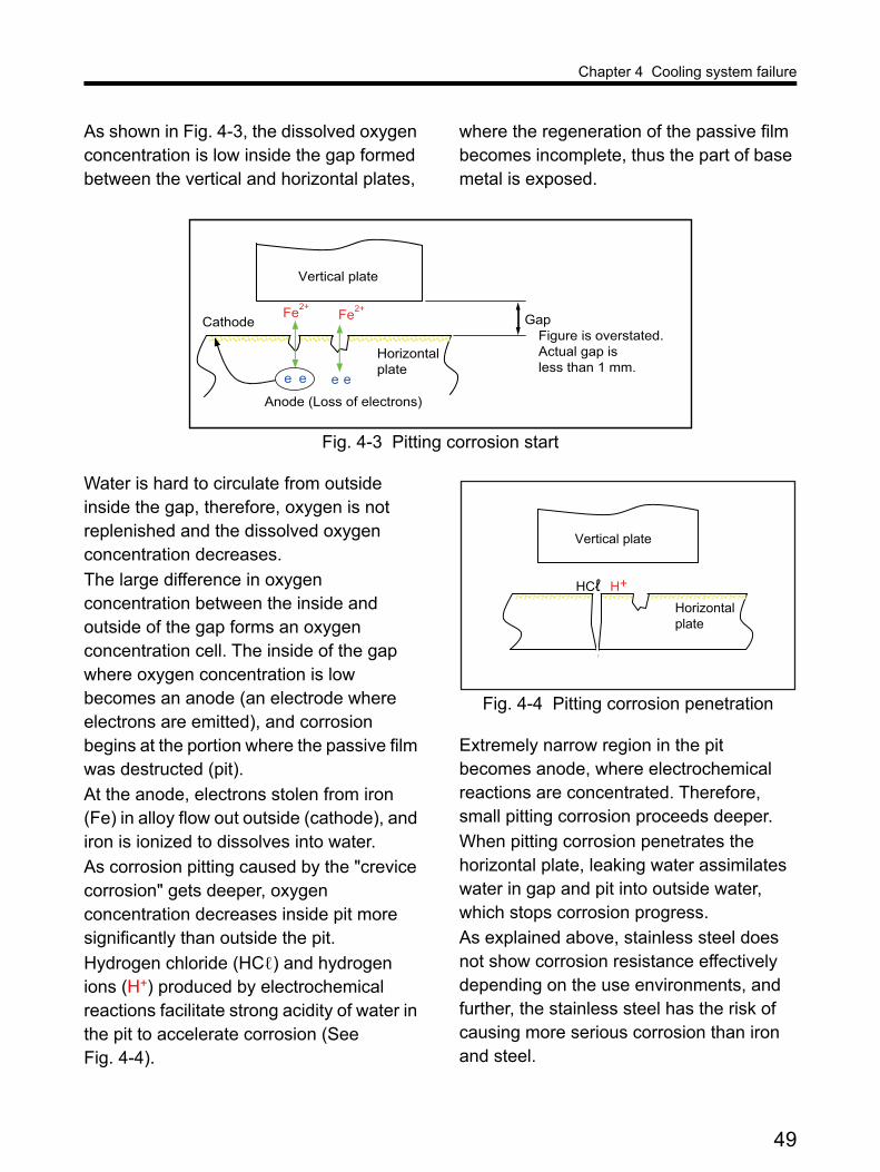
Chapter 4 Cooling system failure
As shown in Fig. 4-3, the dissolved oxygen concentration is low inside the gap formed between the vertical and horizontal plates,
where the regeneration of the passive film becomes incomplete, thus the part of base metal is exposed.
Fig. 4-3 Pitting corrosion start
Water is hard to circulate from outside inside the gap, therefore, oxygen is not replenished and the dissolved oxygen concentration decreases.
The large difference in oxygen concentration between the inside and outside of the gap forms an oxygen concentration cell. The inside of the gap where oxygen concentration is low becomes an anode (an electrode where electrons are emitted), and corrosion begins at the portion where the passive film was destructed (pit).
At the anode, electrons stolen from iron (Fe) in alloy flow out outside (cathode), and iron is ionized to dissolves into water.
As corrosion pitting caused by the "crevice corrosion" gets deeper, oxygen concentration decreases inside pit more significantly than outside the pit.
Hydrogen chloride (HCℓ) and hydrogen ions (H+) produced by electrochemical reactions facilitate strong acidity of water in the pit to accelerate corrosion (See Fig. 4-4).
Fig. 4-4 Pitting corrosion penetration
Extremely narrow region in the pit becomes anode, where electrochemical reactions are concentrated. Therefore, small pitting corrosion proceeds deeper.
When pitting corrosion penetrates the horizontal plate, leaking water assimilates water in gap and pit into outside water, which stops corrosion progress.
As explained above, stainless steel does not show corrosion resistance effectively depending on the use environments, and further, the stainless steel has the risk of causing more serious corrosion than iron and steel.
Horizontal plate
Vertical plate
Anode (Loss of electrons)
Cathode Gap Figure is overstated. Actual gap is less than 1 mm.
Fe2+Fe2+
e e e e
H+HCℓHorizontal plate
Vertical plate
49

Chapter 4 Cooling system failure
According to the Water Supply Act in Japan, the concentration at tap of free residual chlorine added to clean water for disinfection must be 0.1 ppm (0.1 mg/L) or higher. And, on the water quality standard, the chlorine ion concentration must be 200 ppm or lower.
As time goes by, the chlorine concentration decreases, but chlorine ions in the water do not. Therefore, using water in the water tank which is replenished with tap water for a long term is likely to condense chlorine ions.
When stainless steel is used with less corrosive-resistant iron or steel in the cooling system, rust from the iron or steel may adhere to the surface of the stainless steel. And, clearing gaps inside equipment or in pipe connections made of stainless steel is not realistic.
In the prior case, in the cooling system for a standby generator set in which only tap water is used, the stainless steel plate 6 mm thick (18Cr- 8Ni) was penetrated in one year and eight months by pitting corrosion which evolved from crevice corrosion. Therefore, MHIET does not recommend using tanks and piping made of stainless steel for external cooling system using freshwater.
1.2.2 Bimetallic corrosion
When metals with different ionization tendency contact in electrolyte such as water, metal with larger ionization tendency (poorer metal) is ionized to dissolve.
Sacrificial electrode of zinc (Zn) used in ships utilizes this tendency.
There is a difference in ionization tendency between iron and stainless steel although it is not so much as the difference between Zinc and iron.
If stainless steel is used for cooling system piping without any countermeasures, relatively poorer iron and steel is ionized to dissolve into coolant.
Bimetallic corrosion is accompanied by cell action. Therefore, contact region such as connection between stainless steel and steel in water tank or piping must be electrically insulated perfectly.
2. CavitationCavitation erosion is caused by shock waves produced when small bubbles appear and collapse in coolant.
Air dissolved in water at a certain pressure vaporizes to form bubbles when the pressure drops.
When pressure at the suction side of a jacket water pump becomes negative, air separated from coolant and vapor produced by local coolant boiling form bubbles. And, when the coolant is pressurized again by the pump, the bubbles collapse (cavitation) to cause erosion.
In addition, a cylinder liner wall is vibrating by piston slap in engine running. The coolant around the liner repeats bubble formation and crush, depending on the coolant pressure condition, to cause erosion (cavitation erosion).
Cavitation causes serious problems for engine such as pitting in cylinder liner, noise in jacket water pump, and pump efficiency reduction.
50

Chapter 4 Cooling system failure
In order to prevent cavitation, the engine cooling system must be pressurized and coolant including sufficient genuine antifreeze must be used. In addition, the mechanism to separate gases dissolved in the coolant and vent them intothe atmosphere to prevent them invading into the engine cooling system is required.
3. ScalesScale consists of calcium, magnesium, and silica precipitated from water.
High water temperature facilitates scale precipitation. In engine and heat exchanger, scale not only adheres tightly inside the passage for coolant or cooling water to disturb heat dissipation butalso narrows the passage to obstruct heat transfer. When scale adheres seriously, engine overheats.
Removing adhering scale is quite difficult. Special chemicals and mechanical means must be used by specialists. The expense may be comparable to the purchase of new equipment.
And, in general, when a heat exchanger or its components are assembled or disassembled in the cooling system, power supplying facilities must be stopped. Then, the profit loss of electrical power generation and heat recovery has to be taken into consideration.
Soft water whose total hardness is 50 ppm or lower does not cause any scale problem. Any problem rarely occurs in the engine cooling system using proper coolant. Meanwhile, scale causes serious problems in the open-type cooling system using solid water.
Particularly, well water (MHIET does not recommend) has high hardness in general.
In this case, unless water quality is adjusted by continuous blow-down or chemical addition, well water causes severe scale problems.
The above photograph shows scale collected from the plate type heat exchanger 450 hours after engine operation start.
In the high-temperature side of the heat exchanger, engine coolant flowed. Meanwhile, in the low-temperature side where the scale was collected, cooling water (untreated well water) flowedto take excessive heat from cogeneration facilities to cooling tower.
The quality of water source such as river and lake varies depending on the region. Therefore, note that also the hardness of tap water to form scale varies depending on the region.
In other case, an engine almost overheated at midsummer. Then, water was sprayed on a radiator to avoid engine shutdown due to serious failure because of high water temperature.
Photo 4-1 Scale adhered to heat exchanger plate (Extreme example)
51

Chapter 4 Cooling system failure
However, scale contained in the sprayed water deposited on the radiator surface, which led to insufficient heat dissipation to further facilitate overheat.
Scale is formed because water leaves every dissolved impure substance in evaporating.
In the open-type cooling system, cooling water evaporation is unavoidable. Especially, cooling tower uses vaporization heat taken away by water to cool cooling water. The water becomes vapor to diffuse into the atmosphere. Meanwhile, included ingredients are accumulated in the remaining cooling water, thereby increasing concentration.
In order to detect the concentration of calcium, magnesium, or silica which deposits as scale by electrical conductivity indirectly to control the concentration, an automatic continuous blow-down device and technical support by specialists are required.
4. DepositsDeposits reduce the heat transfer equipment capacity.
The following foreign objects deposit in the cooling system.
Ferric hydroxide (red rust) formed by corrosion of iron components which contact with water.Fungi and dust that invades through the open-type heat transfer equipment.Sand or iron powder, cement or crushed stone debris, depending on the installation environment.
Solid foreign objects tend to deposit in the low positions of engine and heat exchanger, the portions where the flow velocity of coolant or cooling water is low, and stagnation points.
The deposits inside the supply air cooler obstruct coolant flow to prevent heat transfer, thereby raising the temperature of supply air and exhaust. In the worst case, engine power may be lowered or the engine may shut down due to serious failure because of abnormally high exhaust temperature.
Deposits can cause differential aeration corrosion.
Under deposited foreign objects, cell action because of the difference in oxygen concentration from the surrounding area facilitates corrosion, and may create holes in piping.
If rust fragments exfoliated in the piping were squeezed into the mechanical seal of a water pump, water might leak at the pump.
The engine cooling system should be the closed type, not the open type, to minimize deposits.
52

Chapter 4 Cooling system failure
5. Salt damage and adhering foreign object
The general corrugated fin type radiator is not so resistant to salt damage.
When the generator set is installed near coast or at the place which sea breeze reaches, outdoor air including salt may invade from the ventilation opening of the engine room or package typeengine-driven unit.
When moisture is added to salt adhering to the radiator core, serious corrosion occurs and water may leak in short period.
In the installation environment in which outdoor air including salt may be sucked in, special filter may have to be mounted on the ventilation opening of the engine room or package.
MHIET supplies the plate fin type radiator for the countermeasure against salt damage. Larger radiator is required to guarantee the cooling capacity like the general corrugated fin type.
Corrosive gas such as hydrogen sulfide as well as saline matter decomposes radiator. And, the gas may decompose the inside of supply air cooler when absorbed by condensation water or adhering matters. Therefore, the radiator or supply air cooler must be checked and exchangedin short period.
Outdoor air sucked in by radiator for heat dissipation contains foreign objects such as floating dust and insects. The foreign objects adhere to fins in passing through the radiator or stay and stick in front of the fins, thereby decreasing the radiator heat dissipation capability.
Night lighting in or around the package type generator set installed outdoors attracts insects flying in the air.
Leak of engine oil, fuel, or coolant in the engine-driven unit accelerates adhesion of foreign objects, thereby decreasing heat dissipation capability early.
When the discharge air outlet or air inlet in the engine room, package, or remote mounted radiator is clogged by fallen snow or ice, the flow of cooling air is obstructed, and the radiator heat dissipation is reduced, and in a severe case, engine may overheat. Therefore, for the installation planning in the snowfall area, the roof of the remote mounted radiator, the ventilation opening with snow protection structure, etc. must be taken into consideration.
53

Chapter 5 Coolant
Solid water must not be used independently as the coolant in the engine cooling system, because the water corrodes metals together with oxygen however clean it may be.
In the category of solid water, particularly, pure water, which is called deionized water, has few impure substances, and is good for the base material of the coolant to mix with additives. However, since various substance ions dissolve in pure water easily, deionized water must not beused independently in the engine cooling system.
If solid water were used independently in the closed cooling system, iron ions from components containing iron in the system would react with oxygen in water to form black rust. In the case of the open type cooling system in which water is endlessly supplied with oxygen by contactwith air, black rust is further oxidized to become red rust and deposit.
1. Water qualitySince at least about 40% of coolant is water, water quality affects coolant property.
In case of tap water, water is taken in from rivers and lakes, its foreign objects are removed by precipitation and filtration, and in addition, the water is disinfected by adding chlorine. Therefore, foreign objects such as solid particles and microbial are rarely contained in tap water.
Tap water quality is harmless to human health. However, every tap water cannot be used unconditionally as the base material of the coolant for the engine cooling system.
In some districts, the source of tap water may be underground water or spring water. In this case, the water contains many mineral matter ions, so the water is hard significantly.
Tap water constituents vary depending on the districts, because tap water comes from river or lake, where various substances from the ground dissolve while rainwater fallen to the ground and spring water from the ground flow or stagnate.
Using extremely hard water forms scale in engine and heat exchanger.
According to the Water Supply Act in Japan, chlorine must be added to raw water for disinfection.
On the water quality standard, the ion concentration of chlorides must be lower than 200 ppm. Meanwhile, the concentration of free residual chlorine at tap must be 0.1 ppm or higher, and the upper limit is not specified. Therefore, when river or lake is polluted due to rainfall and so on, more chlorine is presumed to be added.
1.1 Water propertyIn this section, the following water properties are described to use suitable water as the base material of engine coolant.
1.1.1 pH
pH is the hydrogen ion (H+) concentration indicator, which shows substance acidity/basicity (alkalinity) degree.
pH is 1 to 14, and 7 shows neutrality (neither acidity nor alkalinity).
pH smaller than 7 shows acidity, and pH larger than 7 shows alkalinity.
According to the Water Supply Act, the pH of tap water must be between 5.8 and 8.6.
54

Chapter 5 Coolant
1.1.2 Electrical conductivity
The unit of electrical conductivity is millisiemens per meter (mS/m).
Electrical conductivity is the indicator of electrolyte (dissolved chloride ion) concentration in water, and the average electrical conductivity is 11 mS/m in the rivers in Japan.
Water with higher electrical conductivity contains more electrolyte and solid matter, therefore the water is more corrosive and forms more scale.
In general, the electrical conductivity of water is evaluated with reference to the value at 25°C, and increases approx. 2% per degree rise in the water temperature.
1.1.3 Total hardness
Total hardness is the indicator of water hardness, and is obtained by converting the amount of calcium ion (Ca2+) and magnesium ion (Mg2+) to the amount of calcium carbonate (CaCO3).
In general, much calcium and magnesium are contained in rock and ground, therefore underground water is hard.
According to the Water Supply Act in Japan, the concentration (hardness) of calcium, magnesium, and so on in tap water must be within 300 ppm.
Extremely hard water forms scale inside the cooling system, and the scale adheres to heat-transfer surface to obstruct heat transfer significantly.
1.1.4 M alkalinity
M alkalinity, which is called acid consumption or acid neutralization, is the total amount of alkaline components contained in water indicated in terms of calcium carbonate (CaCO3) amount,
and is the indicator of the resistance to pH decrease (acidification).
In general, water with low M alkalinity (approx. 20 ppm or lower) has strong corrosiveness to deteriorate metals. However, high M alkalinity does not necessarily mean high pH.
High M alkalinity facilitates scale formation.
M of M alkalinity comes from the initial letter of Methyl orange or Methyl red used in titration.
1.1.5 Chlorine ion
Chlorine ions, which are called chloride ions (Cl-), are contained by 10 to 20 ppm in natural water in river and lake. Meanwhile, water that contains high concentration of chlorine ions over 50 ppm is formed by contamination or salt water incorporation.
As described in the section, "Corrosion", note that chloride ions are especially corrosive to stainless steel.
1.1.6 Sulfuric acid ion
Sulfuric acid ions are formed by oxidative decomposition of sulfate or sulfide dissolved from the ground in water. Natural water contains 100 ppm or lower sulfuric acid ion. Meanwhile, water with high concentration of sulfuric acid ions is formed by contamination or salt water incorporation.
Water with high concentration of sulfuric acid ion is corrosive to iron.
1.1.7 Total Fe
Total Fe is the total amount of iron ions (Fe2+) and ferrous hydroxide [Fe(OH)2], and if oxygen is supplied, ferric hydroxide [Fe(OH)3] (red rust) can be formed.
55
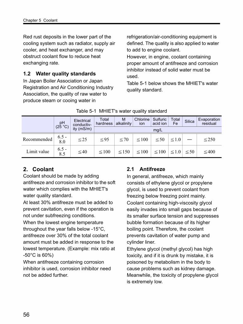
Chapter 5 Coolant
Red rust deposits in the lower part of the cooling system such as radiator, supply air cooler, and heat exchanger, and may obstruct coolant flow to reduce heat exchanging rate.
1.2 Water quality standardsIn Japan Boiler Association or Japan Registration and Air Conditioning Industry Association, the quality of raw water to produce steam or cooing water in
refrigeration/air-conditioning equipment is defined. The quality is also applied to water to add to engine coolant.
However, in engine, coolant containing proper amount of antifreeze and corrosion inhibitor instead of solid water must be used.
Table 5-1 below shows the MHIET's water quality standard.
2. CoolantCoolant should be made by adding antifreeze and corrosion inhibitor to the soft water which complies with the MHIET's water quality standard.
At least 30% antifreeze must be added to prevent cavitation, even if the operation is not under subfreezing conditions.
When the lowest engine temperature throughout the year falls below -15°C, antifreeze over 30% of the total coolant amount must be added in response to the lowest temperature. (Example: mix ratio at -50°C is 60%)
When antifreeze containing corrosion inhibitor is used, corrosion inhibitor need not be added further.
2.1 AntifreezeIn general, antifreeze, which mainly consists of ethylene glycol or propylene glycol, is used to prevent coolant from freezing below freezing point mainly.
Coolant containing high-viscosity glycol easily invades into small gaps because of its smaller surface tension and suppresses bubble formation because of its higher boiling point. Therefore, the coolant prevents cavitation of water pump and cylinder liner.
Ethylene glycol (methyl glycol) has high toxicity, and if it is drunk by mistake, it is poisoned by metabolism in the body to cause problems such as kidney damage. Meanwhile, the toxicity of propylene glycol is extremely low.
Table 5-1 MHIET's water quality standard
pH (25 °C)
Electrical conductiv-ity (mS/m)
Total hardness
M alkalinity
Chlorine ion
Sulfuric acid ion
Total Fe Silica Evaporation
residual
mg/L
Recommended 6.5 - 8.0 25 95 70 100 50 1.0 ― 250
Limit value 6.5 - 8.5 40 100 150 100 100 1.0 50 400
≦ ≦ ≦ ≦ ≦ ≦ ≦
≦ ≦ ≦ ≦ ≦ ≦ ≦ ≦
56

Chapter 5 Coolant
Therefore, MHIET recommends using the propylene glycol type antifreeze with safety taken into consideration.
Coolant containing antifreeze must not be dumped into sewer or river. In Japan, according to the Wastes Disposal and Public Cleansing Act, the coolant must be disposed of properly as industrial waste by the waste disposer authorized by the governor.
Jacket water heater is useful to prevent coolant freeze and maintain the whole engine temperature.
2.2 Corrosion inhibitorWater coexisting with oxygen shows corrosiveness. Therefore, proper additives must be added to coolant to control corrosion.
The engine cooling system is composed of various materials such as iron, aluminum, copper, brass, rubber, etc. Therefore, additives which have anticorrosive effect on the materials must be prepared as corrosion inhibitor.
And, rust preventing agent for one metal must neither decompose nor deteriorate other metal. As bad example, amine is good rust preventing agent for iron, but it is not good for copper.
Silicate is the proper rust preventing agent for aluminum, but strong alkalinity (pH 10) that has to be maintained corrodes aluminum when silicate is consumed.
Further, when coolant gets neutralized with only water replenishment, silicate may get gelled to clog radiators and oil coolers.
The previous amine type corrosion inhibitor contains silicates and rust preventing agent for copper with fine balance.
When the corrosion inhibitor is used for a long time, the above problems occur off balance.
Then, the improved non-amine type corrosion inhibitor that preserves anticorrosive effect in the light of the above cases was released.
MHIET recommends the non-amine type corrosion inhibitor because the amine type forms toxic materials in addition to the above.
2.3 Coolant preparationMHIET recommends genuine "PG GLASSY" and "GLASSY" as rust preventing antifreeze.
When commercially available antifreeze or corrosion inhibitor is used, user must prevent freeze, corrosion, and cavitation. In addition, in this case, bad effects on the metals such as iron, steel, copper, copper alloy, and aluminum, and nonmetal such as rubber and plastics in the engine cooling system must be checked.
The antifreeze concentration must be at least 30% throughout the year at any temperature conditions to prevent cavitation in the engine jacket water pump and cylinder liners.
The antifreeze concentration required to prevent freezing at -15°C depends on the lowest engine temperature in the whole year.
The concentration should be determined with the lowest temperature during the year of an engine itself or its surroundings, not by outdoor temperature.
57

Chapter 5 Coolant
Excessive addition of antifreeze will decrease the heat dissipation capability of the radiator and heat exchanger in the cooling systems.
MHIET recommends the propylene glycol type "PG GLASSY" and ethylene glycol type "GLASSY" as genuine rust preventing antifreeze. The stable additives for corrosion inhibition are effective for all the metallic components used in the engine cooling system, and in addition,do not have bad effects on rubber and plastics. The additives do not contain the amine type corrosion inhibitor which forms nitrosamine that is carcinogenic substance and are environment-friendly.
Fig. 5-1 shows the freezing temperature of coolant containing GLASSY.
Fig. 5-1 Freezing temperature of GLASSY added coolant
When the same amount is added, the coolant with propylene glycol shows higher freezing temperature as compared with ethylene glycol. Therefore, PG GLASSY needs to be used in the concentration shown in Fig. 5-2.
Fig. 5-2 Freezing temperature of PG GLASSY added coolant
However, the case below must be taken into consideration. Suppose that PG GLASSY is added up to 90% of the maximum condensation in an engine-driven unit for winter below -40°C. In this case, if the cooling system does not have extra capability sufficiently when the engine-driven unit is installed at temperature in excess of 35°C, the engine may overheat because propylene glycol is less thermally-conductive compared with ethylene glycol.
When a part of coolant is lost from the engine cooling system, water with the concentration of GLASSY like the concentration in the initial filling must be replenished.
Only the coolant to which PG GLASSY or GLASSY are added can be used for two years at the longest. Meanwhile, in general, replacing the coolant in the major overhaul minimizes the whole maintenance cost. Therefore, the replacement period should be determined referring tothe service manuals for the specific model.
0
10
30
40
50
600 10 20 30 40 50 60 70
Free
zing
tem
pera
ture
(˚C
)
Concentration (volume %)
Lower limit
0
10
20
30
40
50
6050 70 80 9040 100
Concentration (volume %)
Lower limit
60
Free
zing
tem
pera
ture
(˚C
)
58

Chapter 6 Pipe line
The layout and design of pipe line is very important for cooling system to circulate coolant required for engine cooling in an external cooling circuit within the allowable resistance of jacket water pump.
When an external cooling system is shared in two or more engines to save pipe lines, each engine must have the function to open/close coolant circuit in response to its running, stop, and load change. Otherwise, the engine will cause thermal problem.
1. Flow rateCoolant flow rate required to transfer heat rejected from engine to outside is obtained by following formula.
For pure ethylene glycol, the density is 1.12 kg/L at 20°C, and the specific heat is 2.43 kJ/kg°C. Actually used antifreeze may range in density and specific heat, because corrosion inhibitor, etc. are added.
Table 6-1 shows the density and specific heat of solid water and typical coolant containing antifreeze.
The required coolant flow rate in the MHIET generator set is as follows.
Example:
Heat rejection to engine coolant: 26,210 kJ/min Coolant temperature at engine outlet: 93°C Coolant temperature at engine inlet: 85°C
The coolant flow rate required to transfer heat rejected from engine is in inverse proportion to coolant temperature difference between engine inlet and outlet. Therefore, pipe line can be thinner when the temperature difference is increased.
However, large coolant temperature difference between the inlet and outlet requires larger capacity of heat transfer equipment. Then, the total cost-effectiveness of the cooling system should be studied.
In general, the minimum coolant flow rate is required for engine running. Otherwise, coolant may avoid narrow passage of jacket to take a short route easy to pass (short circuit).
For the MHIET engine, the temperature difference between coolant inlet and outlet must be up to 10°C.
V = ΔT · γ · CpQe
Qe: Engine heat rejection (KJ/min)V: Coolant flow rate (L/min)
γ: Density of coolant (kg/L)Cp: Specific heat of coolant (KJ/kg˚C)
Where:
ΔT: Coolant temperature difference between engine inlet and outlet (˚C)
Table 6-1 Density and specific heat (at 85°C)
Solid water Coolant
Density (kg/L) 0.97 1.02
Specific heat (kJ/kg°C) 4.19 3.64
V = = 882 (L/min)(93 - 85) × 1.02 × 3.6426210
59

Chapter 6 Pipe line
2. Pressure
2.1 Pump outletThe head loss (pressure loss) of coolant flowing through the heat transfer equipment and pipe line of cooling system outside engine increases the outlet pressure of jacket water pump.
For the MHIET engine, pressure applied to the pump outlet must be up to 0.3 MPa, regardless of whether the engine runs or stops.
In designing the pipe lines of cooling circuit, sufficient study is required to minimize their bends and straight length.
When coolant flows in the cooling circuit with flow rate required for engine cooling, pressure applied to the outlet of jacket water pump must not exceed the permissible external resistance.
Otherwise, the jacket water pump must be removed from the engine, and a circulating pump with large capacity must be installed.
2.2 Pump inletPressure applied to the inlet of jacket water pump must not exceed 0.1 MPa to avoid water leakage from the pump. Generally, excessive pressure is applied to the pump inlet by static head of heat transfer equipment installed higher than engine. Therefore, a decompression tank described in the section "Installation for excessive head" may have to be arranged between equipment and engine.
Negative pressure may be created at the inlet of jacket water pump in the cooling circuit in which coolant cannot flow sufficiently. Negative pressure at the pump inlet must be avoided absolutely, because it causes cavitation, which may reduce the pump performance or damage the pump.
An expansion tank installed in the cooling circuit is effective in maintaining positive pressure (pressure higher than atmospheric pressure) at inlet of jacket water pump (See Fig. 6-1).
Fig. 6-1 Expansion tank in the engine cooling system
Cooling tower
Expansiontank
Heat exchanger
Engine
Circulatingpump
Jacketwater pump
Less than0.6 m/s
60

Chapter 6 Pipe line
When engine coolant is controlled at the outlet, the expansion tank must be connected to the suction side of the jacket water pump.
Water level at expansion tank applies static pressure to the circuit of the engine cooling system.
If sufficient positive pressure is applied to the inlet of running jacket water pump with head between expansion tank and engine in the designed cooling circuit, a pressure cap is not required for the tank.
If a pressure cap is attached to the expansion tank installed much higher than the engine, the valve opening pressure of the pressure cap is applied to the tank head, Then, the pressure applied tothe inlet of jacket water pump may exceed the permissible maximum pressure. In addition, the temperature in the cooling system decreases after the engine stops, and pressure continues to be applied to the cooling circuit until pressure inside the expansion tank is balanced with atmospheric pressure by coolant shrinkage.
The expansion tank must be arranged at the highest position in the cooling system to separate gas from the system and vent it to atmosphere.
In order to separate air and vapor from coolant, the pipe at the suction side of the pump joined to the expansion tank should be locally thickened and the flow velocity in the pipe should be reduced within 0.6 m/s.
Pipe with nominal diameter of at least 1 inch must be used to connect the expansion tank with the piping at the pump suction side.
The total volume of the expansion tank should be at least 15% of the total coolant amount held in engine, heat transfer equipment, and piping. Expansion volume must be at least 5% of the total coolant amount in the system.
The remaining 10% holds coolant in reserve.
3. Head lossWhen coolant flows in cooling circuit, dynamic pressure (velocity head) and resistance (pressure loss) will be created.
The dynamic pressure is proportional to liquid density and square of flow velocity. The resistance is proportional to kinetic viscosity of liquid, roughness inside passageway, and length of the passageway. Complex calculation method is required to obtain the head loss accurately.
For simplicity, the head loss is roughly calculated in the following sequence.
3.1 Pipe lineFig. 6-2 shows the cooling circuit of the MHIET 800 kW class generator set. Then, the head loss in pipe line is calculated below.
61

Chapter 6 Pipe line
Fig. 6-2 Case: 800 kW generator set
Length of straight piping.Bore diameter (nominal diameter) and length (m) of pipe in a straight line in the whole circuit.Bend, branch, and valve.Nominal diameter and quantity of joints for
pipe line bending and branch and valves in the circuit.
The equivalent length from Table 6-2 is multiplied by the quantity to find the sub-total, and then it is recorded in the table together with the length of straight pipe line (See Table 6-3).
11.5 m
11.0 m
Table 6-2 Equivalent length of pipe joints and valves (m)
Nominal diameter Elbow T joint Gate valve
Globe valve
Angle valveA inch 90° 45° Branch Main
10 3/8 0.40 0.24 0.60 0.12 0.08 3.3 1.6
15 1/2 0.60 0.36 0.90 0.18 0.12 4.5 2.4
20 3/4 0.75 0.45 1.20 0.24 0.15 6.0 3.6
25 1 0.90 0.54 1.50 0.27 0.18 7.5 4.5
32 1 1/4 1.20 0.72 1.80 0.36 0.24 10.5 5.4
40 1 1/2 1.50 0.90 2.10 0.45 0.30 13.5 6.6
50 2 2.10 1.20 3.00 0.60 0.39 16.5 8.4
65 2 1/2 2.40 1.50 3.60 0.75 0.48 19.5 10.2
80 3 3.00 1.80 4.50 0.90 0.59 24.0 12.0
90 3 1/2 3.60 2.16 5.40 1.08 0.72 28.0 14.4
100 4 4.20 2.40 6.30 1.20 0.81 37.5 16.5
125 5 5.10 3.00 7.50 1.50 0.99 42.0 21.0
150 6 6.00 3.60 9.00 1.80 1.20 49.5 24.0
175 7 7.00 4.20 10.5 2.10 1.40 57.8 28.0
200 8 8.00 4.80 12.0 2.40 1.60 66.0 32.0
225 9 9.00 5.40 13.5 2.70 1.80 74.3 36.0
250 10 10.0 6.00 15.0 3.00 2.00 82.5 40.0
300 12 12.0 7.20 18.0 3.60 2.40 99.0 48.0
62

Chapter 6 Pipe line
The flow velocity of coolant and cooling water in the piping should be 1 to 3 m per second.
Lowering the flow velocity requires thick piping, which increases space and cost for the piping installation. On the other hand, excessive flow velocity increases resistance created at pipe lines, then noise may be produced in a cooling system.
Fig. 6-3 shows the relationship between flow rate and flow velocity in the piping.
63

Chapter 6 Pipe line
Fig. 6-3 Head loss at straight pipe
10000
1000
100
10
5
50
500
5000
20002500
15
202530
40
400
300250200
150
1500
3000
4000
100 k150050 5k400300200150403020151
4
3
2
1.5
2.5
25 4k3k2k1.5k
125
100
80
65
50
40
32
25
20
15
10
90
0.2
0.3
0.5
0.81.0
1.5
2.0
3.0
4.0
5.0m/s
300A
250
200
150
10
225
175
Head loss per 1 m straight pipe (Pa)
Flow
rat
e (L
/min
)
10k
64

Chapter 6 Pipe line
The vertical axis indicates flow rate per minute (L), and the right downward sloping line shows flow velocity (m/s). The right upward sloping line shows the nominal diameter of pipe.
Draw a right straight line from the flow rate scale indicated by the vertical axis, and cross the straight line and each nominal diameter line.
The values indicated between two right downward sloping lines across the cross point are the flow velocity range.
Table 6-3 shows the relationship the flow velocity within the proper range and nominal diameters.
And, Fig. 6-3 shows the typical head loss of solid water per 1-m straight pipe.
The vertical axis indicates flow rate per minute (L), and the horizontal axis indicates head loss (Pa) per 1-m straight pipe. The right upward sloping line (pipe size line) shows SGP (Standard gas pipe) pipe with nominal diameter of 10A (3/8 in.) to 300A (12 in.).
The reading in the horizontal axis in the intersection of flow rate line and pipe size line is head loss per 1-m straight pipe. The total length of pipe line in Table 6-3 is multiplied by the head loss per 1-m straight pipe to obtain the head loss of circuit (See Table 6-4).
3.2 EquipmentInternal loss (resistance) of equipment installed at cooling circuit outside engine such as heat exchanger, radiator, and three-way valve can be obtained from the manufacturer or sales agency.
In reference, the required information such as flow rate and temperature of coolant has to be provided.
The head loss in the whole cooling system should be obtained by adding the internal resistance of equipment to the head loss of pipe line.
Table 6-3 Case: Total length of pipe line
Nominal diameter
Straight length (m)
Gate valve.Total length
(m)Equivalent length (m) Qty. Sub total (m)
90 A 22.5 0.72 4 2.88 25.38
100 A 22.5 0.81 4 3.24 25.74
125 A 22.5 0.99 4 3.96 26.46
Table 6-4 Case: Head loss at pipe line
Nominal diameter Total length (m) Head loss per 1m (Pa)
Head loss at pipe line (kPa)
90 A 25.38 600 15.2
100 A 25.74 320 8.2
150 A 26.46 100 2.6
65

Chapter 6 Pipe line
4. Pump capabilityWhen the engine jacket water pump mounted on engine is used to circulate engine coolant in external heat exchanger, etc., the flow rate of the water pump is influenced easily by resistance because it is the centrifugal type. Therefore, the resistance outside the engine must be as low as possible.
Insufficient coolant flow rate reduces engine's cooling capability and overheats the engine to impair the engine reliability. Therefore, the permissible minimum flow rate specified for engine type and operating speed must be achieved.
When OEM or customers plan an external cooling system, they must refer to the MHIET dealer for the permissible minimum flow rate of engine coolant and the performance of the jacket water pump. Then, they need to present the engine type and operating speed to the dealer.
Suppose that the jacket water pump of the 800 kW generator set in Section 3 (used to calculate head loss) has the capability shown in Fig. 6-4 at engine speed of 1800 min-1(rpm). The permissible maximum external resistance in order to achieve pump flow rate of 882 L/min shall be 5.2 kPa.
Fig. 6-4 Capability of jacket water pump
According to Table 6-4 in Section 3.1, the head loss is 15.2 kPa at nominal pipe diameter of 90A and 8.2 kPa at nominal diameters of 100A. Therefore, piping with nominal diameter of 125A must be designed to keep the head loss within 2.6 kPa.
And, the internal resistance of remote mounted radiator must be kept within 2.6 kPa which is obtained by subtracting head loss of 2.6 kPa at piping from the permissible external resistance of5.2 kPa at pump.
5. Design considerations
5.1 Pipe line planningPipe line must minimize flow resistance and no air must be trapped in piping.
Compressibility of gas such as air and steam may block the flow of coolant and cooling water in circuit.
And, if pump pressure is reduced when gas appears at the suction side of pump, cavitation may occur.
11001000900800700600
5
4
3
2
1
0
6
Pump flow rate (L/min)
1800min-1
Ext
erna
l res
ista
nce
(kP
a)
66

Chapter 6 Pipe line
The pipe lines must be straight (without ups and downs) to prevent air trapping.
Gas tends to gather at the highest position of piping, where gas is trapped (See Fig. 6-5).
Fig. 6-5 Pipe line in which air tends to accumulate
Proper venting mechanism is required in the place where gas is trapped.
An expansion tank has another important function to collect trapped air and discharge the air to the atmosphere. The expansion tank must be arranged at the highest position in the cooling system and be connected with vent line for air trapping (See Fig. 6-6).
Fig. 6-6 Vent line to expansion tank
Gas must be collected by air-trap device or slightly larger pipe arranged at the main piping, and be taken to the expansion tank through vent line.
Vent line with nominal diameter of approx 8A (1/4 in.) must be installed with continuous upward slope of at least 50 mm per meter.
When larger pipe is used to the vent line for piping strength, etc., metering valve must be attached at the vent line to minimize the flow of coolant and cooling water.
Then, pressure in the main piping must be kept in response to the quantity of gas and coolant or cooling water that flows from vent line to the expansion tank. Therefore, a connection pipe with nominal diameter of least at 25A must be connected between the expansion tank and main piping.
Expansion tank
Air-trap deviceVent line
Main pipingConnection pipe
67

Chapter 6 Pipe line
When two or more vent lines are connected to the expansion tank, the connection pipe must have enough cross-section area to return all inflow to the main piping with low resistance.
5.2 Vibration isolationVibration from engine-driven unit may be transmitted to pipe lines far away.
Especially the pipe lines connected to a unit supported by vibration isolators are greatly vibrated due to relative motion of fixed piping and fluctuating unit.
Piping joints must absorb fluctuation created at engine-driven unit in its starts and stops and thermal expansion of piping.The joints used for standby generator set must not be damaged even at the maximum displacement of earthquake in accordance with the legal standard.
Pipe vibration transmits to piping supports, and also affects a building depending on the conditions.
Flexible joints must be used to connect engine with pipe lines to isolate vibration of engine-driven unit. Vibration still transmitted from engine or by coolant pulsation may be isolated using pipe supports equipped with vibration isolators.
Rubber hose should not be used for pipe joints in the cooling system except engine mounted radiator. The joints must be made from materials resistant to the highest temperature and pressure of coolant and cooling water, and the lowest ambient temperature in stop state.
And, the surface of the pipe joints must have sufficient resistance to substance that is expected to adhere such as lubricating oil, fuel, antifreeze, coating, and cleaning solvent.
The pipe joints used for standby generator set must have nonflammable surface in accordance with the laws and regulation in Japan.
5.3 Heat insulationFor heat dissipation or recovery system using cooling water without antifreeze, any measure for freeze proofing except antifreeze may have to be taken.
When generator set or cogeneration facility does not run for 24 consecutive hours or for a definite period, the temperature of the cooling water will decrease during engine stop.
Temperature of small pipe decreases abruptly with heat release, because it has less cooling water (less heat). Therefore, the small pipe may freeze after engine stops in the subfreezing environment.
And, circuit in which hot cooling water rarely flows in engine running may freeze, because heat is not stored in the circuit.
Pipe lines that may freeze must be kept warm (insulated). In extremely low-temperature installation environment, heater must be arranged in piping, etc.
Frozen cooling water may expand to crack or break portions weaker than pipes such as joint and gauge.
Generally, circulation pump may freeze, because it holds too little water for its large surface area and thermally conductive area.
The pipe lines of the engine cooling system and heat recovery system must be heat-insulated, depending on the installation environment.
68

Chapter 6 Pipe line
In order to protect operators against burn injury in checking or maintenance, high-temperature piping must be heat-insulated for safety.
When pipe lines are installed at place that requires ventilation, heat diffused from pipe surface will increase air quantity required to maintain room temperature.
In cogeneration facility, heat diffused from the piping surface becomes non-recoverable energy.
Generally, pipe surface should be heat-insulated (kept warm), because more high-temperature pipe line diffuses more heat into ambient air.
Glass wool is commonly used for insulation. However, note that the materials containing asbestos may be also used in old facilities.
5.4 Service convenienceThe cooling system should be arranged near engine to minimize pipe line length. On the other hand, maintenance of cooling system and engine-driven unit must be taken into consideration.
Daily check and periodic overhaul are required for the engine, driven equipment and cooling system components. Therefore, an access aisle for personnel, space for checking, and temporary place for equipment assembly/disassembly and transport must be provided.
Gate valves such as butterfly valve must be arranged in the piping such as the engine inlet/outlet and the connection with heat exchanger, circulating pump, three-way valve, and expansion tank to minimize coolant drained in equipment overhaul or assembly/disassembly.
However, the valve location must be determined carefully because coolant may remain inside when exchanged.
Drain valves must be arranged in appropriate positions so that coolant can be drained through hose or piping. And, drainage trench or drip pan should be installed to collect coolant leaked fromthe connection.
Coolant drained from the engine cooling system must not be dumped directly into river or sewage line in accordance with laws and regulations.
For easy check of coolant volume, the expansion tank should be equipped with a pressure resistant water level gauge (sight glass) which can clean the inner surface. When the expansion tank is installed in the high location which is defined as high place in accordance with Industrial Safety and Health Act, a legal lifting and lowering device must be provided.
Outlet of circulating pump in the heat recovery circuit should be equipped with a pressure gauge and simple flow meter.
When pump, etc. do not operate, a low water flow alarm device will operate. Meanwhile, system malfunction can be perceived in advance by the daily check of pressure or flow rate of circulating cooling water.
69

REVISION HISTORY
REVISION HISTORY
Pub. No.
MITSUBISHI ENGINE GENERATOR SET
29Z06-00620
Cooling system
GUIDE TO CAPACITY SELECTION AND INSTALLATION PLANNINGTitle
Revision Issued Description
- August 2017 First edition issued.
- August 2018 Description of resin fan added.
- July 2021Changed the document number, cover Pub. No. 98CAB-60610 (issued in Au-gust 2017) and issued it as a new publication.

MITSUBISHI ENGINE GENERATOR SETGUIDE TO CAPACITY SELECTION AND INSTALLATION PLANNINGCooling system
Issued in July 2021
Pub. No. 29Z06-00620
Issued by Mitsubishi Heavy Industries Engine & Turbocharger, Ltd.
3000, Tana, Chuo-ku, Sagamihara, Kanagawa, 252-5293, Japan
Edited by MHI Sagami High-tech LTD.
Printed and bound by Fuji Film Service Link Co., Ltd.
• The manual with incorrect collating or missing pages is to be replaced.
• Without written approval from the publisher, for all or some part of this manual, unauthorized reproduction, copy,
reprinting in any way or method are prohibited.

Copyright © 2021 MITSUBISHI HEAVY INDUSTRIES ENGINE & TURBOCHARGER, LTD. All Rights Reserved.
Printed in Japan

July 20
21
MITSUBISHI ENGINE GENER
Pub
. No. 2
9Z0
6-006
20ATOR SET
Co
olin
g s
yste
mG
UID
E TO
CA
PA
CITY
SE
LEC
TION
AN
D IN
STA
LLATIO
N P
LAN
NIN
G


![FXTQ-PA Air Handling Unit - daikinac.com · Capacity Tables EDUS391000-F12 10 FXTQ-PA 6. Capacity Tables 6.1 Cooling Capacity FXTQ-PA [Cooling capacity] Unit size Outdoor air temp](https://img.dokumen.tips/doc/110x75/5cab3caa88c993135e8d1589/fxtq-pa-air-handling-unit-capacity-tables-edus391000-f12-10-fxtq-pa-6-capacity.jpg)