Embed Size (px)
Citation preview

Cooling for Hadron Beams
Yaroslav Derbenev
Thomas Jefferson National Accelerator Facility
The 4th EIC Workshop
Hampton, May 19-23, 2008
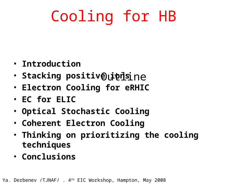
Cooling for HB
• Introduction• Stacking positive ions• Electron Cooling for eRHIC• EC for ELIC• Optical Stochastic Cooling• Coherent Electron Cooling• Thinking on prioritizing the cooling techniques• Conclusions
Outline
Ya. Derbenev /TJNAF/ . 4th EIC Workshop, Hampton, May 2008
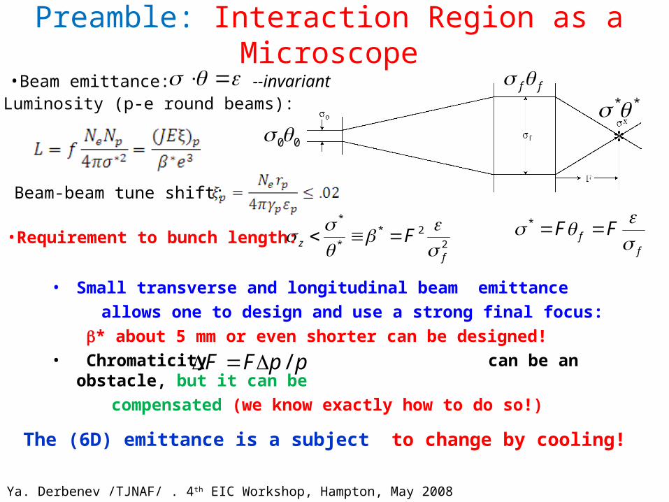
Preamble: Interaction Region as a Microscope
• Small transverse and longitudinal beam emittance
allows one to design and use a strong final focus:
* about 5 mm or even shorter can be designed!
• Chromaticity can be an obstacle, but it can be
compensated (we know exactly how to do so!)
00
ff**
f
f FF *
2
2*
*
*
f
z F
•Luminosity (p-e round beams):•Beam emittance:
•Requirement to bunch length:
ppFF /
The (6D) emittance is a subject to change by cooling!
Ya. Derbenev /TJNAF/ . 4th EIC Workshop, Hampton, May 2008
--invariant
Beam-beam tune shift:

What is Beam Cooling?
• One needs a media with which the beam should interact incoherently
• An individual charged particle creates an effective charge polarization of the media (image charge)
• In response, particle motion is effected by the image field, that decelerates the particle relatively the beam frame - this is cooling!
• Feedback with the right receiver - kicker phasing can be used in order to amplify the response
• Influence of image fields from particle neighbors can only decrease the cooling effect (shield effect)
• The achievable cooling rate and equilibrium is limited by noise in the media and amplifier
Ya. Derbenev /TJNAF/ . 4th EIC Workshop, Hampton, May 2008
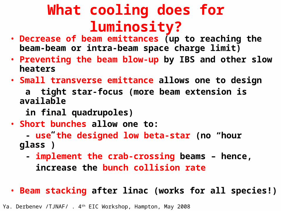
What cooling does for luminosity?
• Decrease of beam emittances (up to reaching the beam-beam or intra-beam space charge limit)
• Preventing the beam blow-up by IBS and other slow heaters
• Small transverse emittance allows one to design a tight star-focus (more beam extension is
available in final quadrupoles) • Short bunches allow one to: - use the designed low beta-star (no “hour
glass”) - implement the crab-crossing beams – hence, increase the bunch collision rate
• Beam stacking after linac (works for all species!)Ya. Derbenev /TJNAF/ . 4th EIC Workshop, Hampton, May 2008

Cooling techniques and ideasRadiation Cooling (RC) Maxwell-Lorentz demon 1950th works in e± colliders, can be used in LHC..
Ionization Cooling (IC) Shrinking before plague (muons…) 1966/1981 under development towards the Neutrino Factory and Muon Collider!
Electron Cooling (EC) Thermostat of the relativistic engineer
1966 -used at low and medium energies -under development for
colliders
Stochastic Cooling (SC) van der Meer’s demon (RF feedback) 1968 used
Coherent Electron Cooling (CEC) Spoiled hybrid of EC and SC 1980 development just started…
Optical Stochastic Cooling (OSC) Max’s demon 1993 (RC+optical feedback) development to start…Ya. Derbenev /TJNAF/ . 4th EIC Workshop, Hampton, May 2008

Electron Cooling: The thermostat of a relativistic engineer
Landau liked to call me “The relativistic engineer”, I am very proud of that. Gersh
Budker
Do not renounce from prison andmoney bag
Kinetic equation (plasma relaxation) was derived by Landau in 1937. But… can it work for beams? It does! Yet very interesting and important phenomena have been discovered (magnetized cooling, super-deep cooling, christaline beams…)
Ya. Derbenev /TJNAF/ . 4th EIC Workshop, Hampton, May 2008
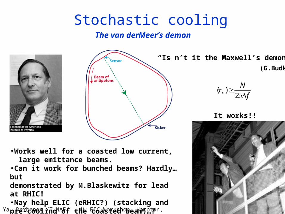
Stochastic cooling
“Is n’t it the Maxwell’s demon?”
(G.Budker)
f
Nc
2
)(
The van der Meer’s demon
It works!!
•Works well for a coasted low current, large emittance beams.•Can it work for bunched beams? Hardly… but demonstrated by M.Blaskewitz for lead at RHIC! •May help ELIC (eRHIC?) (stacking and pre-cooling of the coasted beam)…?
Ya. Derbenev /TJNAF/ . 4th EIC Workshop, Hampton, May 2008

-2.5
-2.0
-1.5
-1.0
-0.5
0.0
Np = 186e10 Np = 124e10 Np = 51e10Co
oli
ng
rat
e [
mm
mra
d p
er h
ou
r]
Fast H Fast V
2-4 GHz vertical
-2.5
-2.0
-1.5
-1.0
-0.5
0.0
Np = 186e10 Np = 124e10 Np = 51e10Co
oli
ng
rat
e [
mm
mra
d p
er h
ou
r]
Fast H Fast V
2-4 GHz horizontal
-2.5
-2.0
-1.5
-1.0
-0.5
0.0
Np = 186e10 Np = 124e10 Np = 51e10
Co
oli
ng
rat
e [
mm
mra
d]
Fast H Fast V
1-2 GHz horizontal
A 1/N-like dependence is clearly visible for the 2-4 GHz system but not for the other two systems (although the 1-2 GHz system shows some dependence on the # of pbars)
Stochastic Cooling rate as function of # pbars (‘Fast Schottky’)
Ya. Derbenev /TJNAF/ . 4th EIC Workshop, Hampton, May

EC in Fermilab’s Recycler ring
0
50
100
150
200
250
300
350
400
0 5 10 15 20
Time, hr
Nu
mb
er
of
an
tip
roto
ns
, E
10
-0.5
0
0.5
1
1.5
2
2.5
3
3.5
Ve
rtic
al
e-b
ea
m o
ffs
et,
mm
0
20
40
60
80
100
120
140
0 5 10 15 20
Time, hr
Lo
ng
. e
mit
tan
ce
, e
Vs
0
2
4
6
8
10
12
14
Ho
r. e
mit
tan
ce
, m
m*m
rad
Electron cooling is used at the Recycler for cooling 8 GeV pbars 4.34 MeV, 0.1 A DC electron beam
Primarily longitudinal coolingTo free space for the next antiproton injection from Accumulator ring
Cooling strength is regulated by a vertical offset of the electron beam in the cooling section
Most of the time, e- beam is shifted by ~2 mm to maximize the life timeMoved on axis before extraction to minimize emittances of the extracted beam
Ya. Derbenev /TJNAF/ . 4th EIC Workshop, Hampton, May
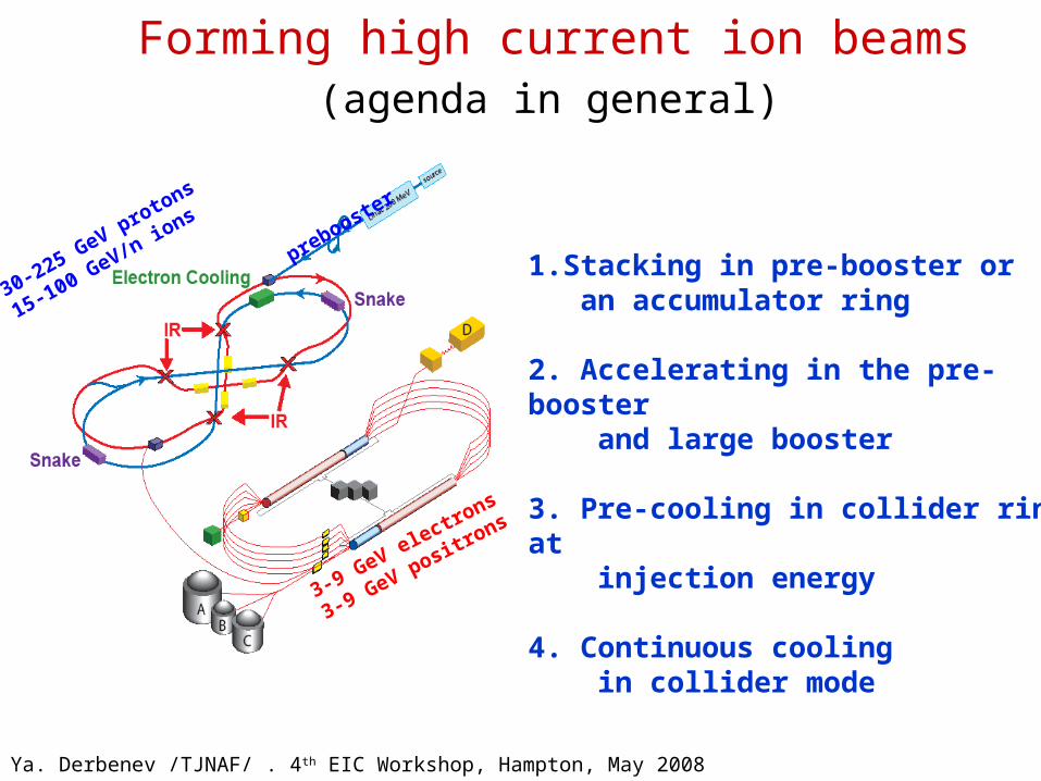
Forming high current ion beams (agenda in general)
3-9 GeV electrons
3-9 GeV positrons
30-225 GeV protons
15-100 GeV/n ions
prebooster
1.Stacking in pre-booster or an accumulator ring
2. Accelerating in the pre-booster and large booster
3. Pre-cooling in collider ring at injection energy
4. Continuous cooling in collider mode
Ya. Derbenev /TJNAF/ . 4th EIC Workshop, Hampton, May 2008
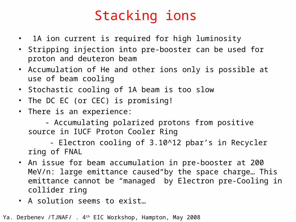
Stacking ions
• 1A ion current is required for high luminosity• Stripping injection into pre-booster can be used for proton and
deuteron beam• Accumulation of He and other ions only is possible at use of beam
cooling• Stochastic cooling of 1A beam is too slow• The DC EC (or CEC) is promising!• There is an experience:
- Accumulating polarized protons from positive source in IUCF Proton Cooler Ring
- Electron cooling of 3.10^12 pbar’s in Recycler ring of FNAL• An issue for beam accumulation in pre-booster at 200 MeV/n: large
emittance caused by the space charge… This emittance cannot be “managed” by Electron pre-Cooling in collider ring
• A solution seems to exist…
Ya. Derbenev /TJNAF/ . 4th EIC Workshop, Hampton, May 2008

Stochastic Cooling and Stacking of Ions An optimistic scenario
Multi-turn (10 – 20) injection from 285 MeV SRF linac to pre-booster
Stochastic damping of injected beam
Accumulation of 1 A coasted beam at space charge limited emittance
RF bunching and accelerating to 3 GeV
Inject into large booster Fill large booster, accelerate to 30
GeV Inject into collider ring Transverse stochastic cooling of 1
A coasted ion beam in collider ring
At this stage, Ion beam is ready for electron cooling
Beam Energy MeV 200
Momentum Spread % 1
Pulse current from linac mA 20
Cooling time min 1.5
Accumulated current A 1
Stacking cycle /fill LB duration
min 4/60
Beam emittance, norm. μm 12
Laslett tune shift 0.03
Stacking proton beam in pre-booster with stochastic cooling
Ya. Derbenev /TJNAF/ . 4th EIC Workshop, Hampton, May 2008

Stacking positive ions by use of DC EC
Accumulator Ring with DC EC Design advancements
:Circumference m 50 Beam stacking in one o f two
Arc radius m 3 circular modes matched with
Crossing straights length m 2 x 15 solenoid of cooling section
Energy/u MeV 200
Electron current A 1 This concept allows one to
Electron energy KeV 100 overcome space charge
Cooling time for protons ms 10 limit on 4D emittance,
Stacked ion current A 1 hence, increase EC pre-
Large norm.emittance cooling rate in collider ring
after stacking µm 16
Accumulation time s 10
Stacking of positive fully stripped polarized and unpolarized ions can be realized in the accumulator-cooler ring (ACR) with electron cooling. Such method has been successfully used for accumulating of polarized beam in Proton Cooler Ring of IUCF
Ya. Derbenev /TJNAF/ . 4th EIC Workshop, Hampton, May 2008

Requirements for eRHIC
1. Protons (250 GeV): 2. Au ions (100 GeV): Bunch intensity: 2e11 Bunch intensity: 1.1e9 95%, normalized emittance: 6 m 95%, normalized emittance: 2.4 m
Rms bunch length: 0.2 m Rms bunch length: 0.2 mPeak luminosity: 2.6e33 Peak luminosity: 2.9e 33
Requires pre-cooling:
Au ions: factor of 6 reduction in initial emittance
Protons: factor of 3-2 reduction in initial emittance
Such electron cooling is possible based on RHIC-II electron cooler with 703 MHz SRF gun.
Ya. Derbenev /TJNAF/ . 4th EIC Workshop, Hampton, May 2008

Pre-cooling of Au ions (N=1e9)
Ya. Derbenev /TJNAF/ . 4th EIC Workshop, Hampton, May 2008

Pre-cooling of protons (N=2e11)
Ya. Derbenev /TJNAF/ . 4th EIC Workshop, Hampton, May 2008

Electron cooling section at RHIC 2 o’clock IPElectron cooling section at RHIC 2 o’clock IP
Each electron beam cools ions in Yellow ring of RHIC then the same beam is turned around and cools ions in Blue ring of RHIC.
`
100 m
IP2
ER
L
helical wigglers
e-
e-
e-
RHIC triplet RHIC triplet
10 m
solenoids
Ya. Derbenev /TJNAF/ . 4th EIC Workshop, Hampton, May 2008

Energy Recovery Linac (ERL) for RHIC-II
Cooling of Au ions at 100 GeV/n:• 54.3 MeV electron beam • 5nC per bunch • rms normalized emittance < 4 m• rms momentum spread < 5×10⁻⁴
Courtesy D. Kayran
D. Kayran, PAC07
Ya. Derbenev /TJNAF/ . 4th EIC Workshop, Hampton, May 2008

R&D ERL at BNL
5 cell cavity successfully processed
0.5 ampere SRF gun – under construction
703 MHz 5 cell SRF cavity designed by BNL and
fabricated by Advanced Energy Systems.
The cavity has reached its specification of 20 MV/m
at a Q of 1×10¹⁰ .
Ya. Derbenev /TJNAF/ . 4th EIC Workshop, Hampton, May 2008

EC Test bed for RHIC-II and eRHIC
Commissioning starts February 2009
Ya. Derbenev /TJNAF/ . 4th EIC Workshop, Hampton, May 2008
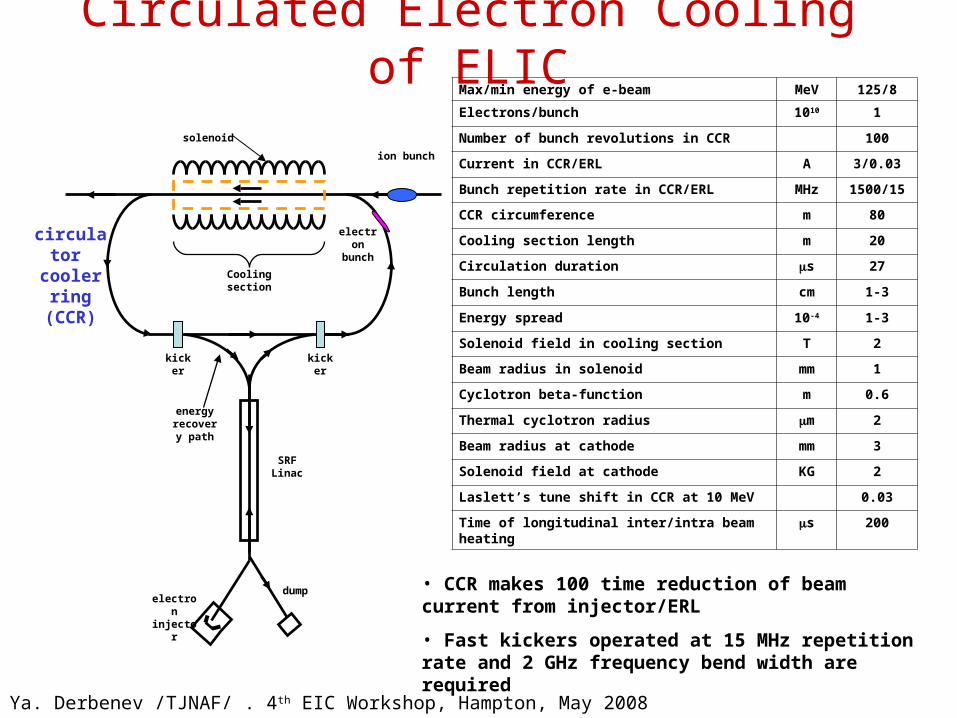
Circulated Electron Cooling of ELIC
ion bunch
electron bunch
circulator cooler
ring (CCR)
Cooling section
solenoid
kicker
kicker
SRF Linac
dumpelectron
injector
energy recovery
path
Max/min energy of e-beam MeV 125/8
Electrons/bunch 1010 1
Number of bunch revolutions in CCR 100
Current in CCR/ERL A 3/0.03
Bunch repetition rate in CCR/ERL MHz 1500/15
CCR circumference m 80
Cooling section length m 20
Circulation duration s 27
Bunch length cm 1-3
Energy spread 10-4 1-3
Solenoid field in cooling section T 2
Beam radius in solenoid mm 1
Cyclotron beta-function m 0.6
Thermal cyclotron radius m 2
Beam radius at cathode mm 3
Solenoid field at cathode KG 2
Laslett’s tune shift in CCR at 10 MeV 0.03
Time of longitudinal inter/intra beam heating s 200
• CCR makes 100 time reduction of beam current from injector/ERL
• Fast kickers operated at 15 MHz repetition rate and 2 GHz frequency bend width are required
Ya. Derbenev /TJNAF/ . 4th EIC Workshop, Hampton, May 2008

Cooling Time and Ion Equilibrium
* max.amplitude** norm.,rms
Cooling rates and equilibrium of proton beam
yx /
Parameter Unit Value
Value
Energy GeV/MeV 30/15
225/123
Particles/bunch 1010 0.2/1
Initial energy spread* 10-4 30/3 1/2
Bunch length* cm 20/3 1
Proton emittance, norm* m 1 1
Cooling time min 1 1
Equilibrium emittance , **
m 1/1 1/0.04
Equilibrium bunch length**
cm 2 0.5
Cooling time at equilibrium
min 0.1 0.3
Laslett’s tune shift (equil.)
0.04 0.02
Multi-stage cooling scenario:
• 1st stage: longitudinal cooling at injection energy (after transverses stochastic cooling)
• 2nd stage: initial cooling after acceleration to high energy
• 3rd stage: continuous cooling in collider mode
Ya. Derbenev /TJNAF/ . 4th EIC Workshop, Hampton, May 2008

Electron Cooling of Ions in ELICStaged cooling
Start electron cooling (longitudinal) in collider ring at injection energy, Continue electron cooling (in all dimension) after acceleration to high energy
F(v)
||
)0(
dv
tdN p
||
)(
dv
tdN p
v0
)(tv e
Dispersive cooling Compensates for lack of transverse cooling rate at high energies
Flat beam coolingBased on flattening ion beam by reduction of coupling IBS rate at equilibrium becomes reduced compared to cooling rate
Sweep cooling • After transverse stochastic
cooling, ion beam has a small transverse temperature but large longitudinal one.
• Use sweep cooling to gain a factor of longitudinal cooling time
Ya. Derbenev /TJNAF/ . 4th EIC Workshop, Hampton, May 2008

Injector and ERL for EC in ELIC
• ELIC CCR driving injector 30 mA@15 MHz, up to 125 MeV energy, 1 nC bunch charge, magnetized
• Challenges Source life time: 2.6 kC/day (state-of-art is 0.2 kC/day)
source R&D, & exploiting possibility of increasing evolutions in CCR
High beam power: 3.75 MW Energy Recovery• Conceptual design
High current/brightness source/injector is a key issue of ERL based light source applications, much R&D has been done
We adopt light source injector as initial baseline design of ELIC CCR driving injector
• Beam qualities should satisfy electron cooling requirements (based on previous computer simulations/optimization)
500keV DC gun
solenoids
buncher
SRF modules
quads
Ya. Derbenev /TJNAF/ . 4th EIC Workshop, Hampton, May 2008

Fast Kicker for Circulator Cooling Ring• Sub-ns pulses of 20 kW and 15 MHz are
needed to insert/extract individual bunches.
• RF chirp techniques hold the best promise of generating ultra-short pulses. State-of-Art pulse systems are able to produce ~2 ns, 11 kW RF pulses at a 12 MHz repetition rate. This is very close to our requirement, and appears to be technically achievable.
• Helically-corrugated waveguide (HCW) exhibits dispersive qualities, and serves to further compress the output pulse without excessive loss. Powers ranging from up10 kW have been created with such a device.
Estimated parameters for the kicker
Beam energy MeV 125
Kick angle 10-4 3
Integrated BdL GM 1.25
Frequency BW GHz 2
Kicker Aperture Cm 2
Peak kicker field G 3
Kicker Repetition Rate
MHz 15
Peak power/cell KW 10
Average power/cell W 15
Number of cells 20 20
kicker
kicker
• Collaborative development plans include studies of HCW, optimization of chirp techniques, and generation of 1-2 kW peak output powers as proof of concept.
• Kicker cavity design will be considered
Ya. Derbenev /TJNAF/ . 4th EIC Workshop, Hampton, May 2008

Coherent Electron Cooling
or
how the van der Meer’s demon can spoil
thermostat of the relativistic engineer
Ya. Derbenev /TJNAF/ . 4th EIC Workshop, Hampton, May 2008

History of CEC idea (1980-91-95-2007)
Coherent electron cooling (CEC) was proposed 27 years ago
What changed in last 10 years?
• Relativistic DC EC realized (FNAL)
• ERL realized (JLab)
• SASE FEL realized (UCLA - DESY)
• ERL-based HEEC on the way (BNL)
And more…
• CEC advantages/disadvantages compared to:
EC : Gain in cooling rate
Complicate BT
SC : Very large FB (30 GHz – optics)
Precise phasing required
OSC : Effective in a wide energy range
Small signal delay
Intense e-beam required
Signal gain is limited
• General idea: amplify response of e- beam to an ion by a micro-wave instability of the beam
• A few instabilities have been shown
Ya. Derbenev /TJNAF/ . 4th EIC Workshop, Hampton, May 2008
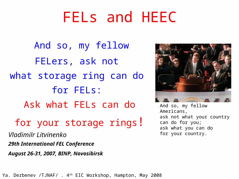
FELs and HEEC
And so, my fellow Americans, ask not what your country can do for you; ask what you can do for your country.
And so, my fellow FELers, ask
not
what storage ring can do for
FELs:
Ask what FELs can do
for your storage rings!Vladimilr Litvinenko29th International FEL Conference
August 26-31, 2007, BINP, Novosibirsk
Ya. Derbenev /TJNAF/ . 4th EIC Workshop, Hampton, May 2008

Optical stochastic cooling (OSC) Max’s demon (by Max Zolotorev, 1993)
----Proton radiates light in undulator (“receiver”)
----optical amplifier----
---“proton interacts with the amplified light in
the end undulator “kicker”)
Ya. Derbenev /TJNAF/ . 4th EIC Workshop, Hampton, May 2008
2000 - OSC considered for cooling of halo particles in the VLHC, by Barletta, Chattopadhyay, Zholents, Zolotorev

Why we need OSC if we have electron cooling
4 2 0 2 40
2
4
6
8
10
.
Cooling rate
0 2 4 6 8 100
0.5
1
1.5
.
Optical stochastic cooling can effectively reduce number of the particles in the beam tails. This will increase lifetime of the beam and reduce detectors background. Custom beam shaping might be possible.
OSC
Electron cooling
Beam profile
Ya. Derbenev /TJNAF/ . 4th EIC Workshop, Hampton, May 2008

Optical Stochastic Cooling
Amplified signal
s
p
Pump laser
i = p - s;
kp = ks + ki
Gold beam
s
p
Horizontal and longitudinal cooling time 1hr for the full gold beam requires 16W of power
= 12 mBandwidth ~ 3 THz
Optical amplifier on 3.5 cm CdGeAs2
crystal with d14=236 pV/m
LDRD test at ATF for Optical Parametric Amplification
Freshly grown crystals at Lockheed Sanders, NH
Ya. Derbenev /TJNAF/ . 4th EIC Workshop, Hampton, May 2008

Optical Parametric Amplifier OPA
Parametric process is photon interaction in which one high frequency photon is annihilated and two lower frequency photons are created, i.e.: (pump) =(signal) +(idler) where photon energy is conserved. In addition, photon momentum is conserved by the wave vectors: k(pump) =k(signal) +k(idler) .
3 cm length crystal → intensity gain 3 105
Ya. Derbenev /TJNAF/ . 4th EIC Workshop, Hampton, May 2008

Critical studies on Cooling for Hadrons
• Pre-cooling for eRHIC: Non-magnetized, space charge dominated e-beam transport
• CEC for eRHIC: all physics and design
• EC for ELIC: ERL - CCR super-fast kicker for e-beam
• OSC (of “beam halo”): Parametric optical amplifier
• SC for beam stacking and pre-cooling (ELIC):
Limits for coasted beams
• DC EC (and CEC) for beam stacking (alternative to SC): Accumulator-cooler design and all beam physics
Ya. Derbenev /TJNAF/ . 4th EIC Workshop, Hampton, May 2008

My view of Current prioritization of potential employment of cooling techniques at EIC
by taking into account :
Potential efficiency + Conceptual readiness + Proximity to realization
Service:
I II III IV
Stacking DC EC DC CEC SC
Pre-cooling HE EC CR EC SC HE CEC
Core Cooling CR EC HE CEC
Tail cooling OSC HE CEC HE EC
EC – electron cooling; DC - direct current; HE - high energy (ERL based)
CR – cirulator ring; CEC - coherent EC; SC - stochastic cooling;
OSC - optical stochastic cooling
Ya. Derbenev /TJNAF/ . 4th EIC Workshop, Hampton, May 2008

Conclusions
• The studies and designs of cooling for EIC are getting mature. The projects are well profiled in the goals and expected performance.
• The engineering works and test studies for 1 hundred MeV scale ERL started at BNL. A prototype of ERL will be built, which, as minimum, will serve pre-cooling of ions to reach luminosity in eRHIC.
• Conceptual development of 125 MeV ERL + Circulator Ring scheme of electron cooling for ELIC will finalize soon (in 1-1.5 year) at JLab. Could such scheme also be implemented in eRHIC to raise the cooler efficiency?
Ya. Derbenev /TJNAF/ . 4th EIC Workshop, Hampton, May 2008
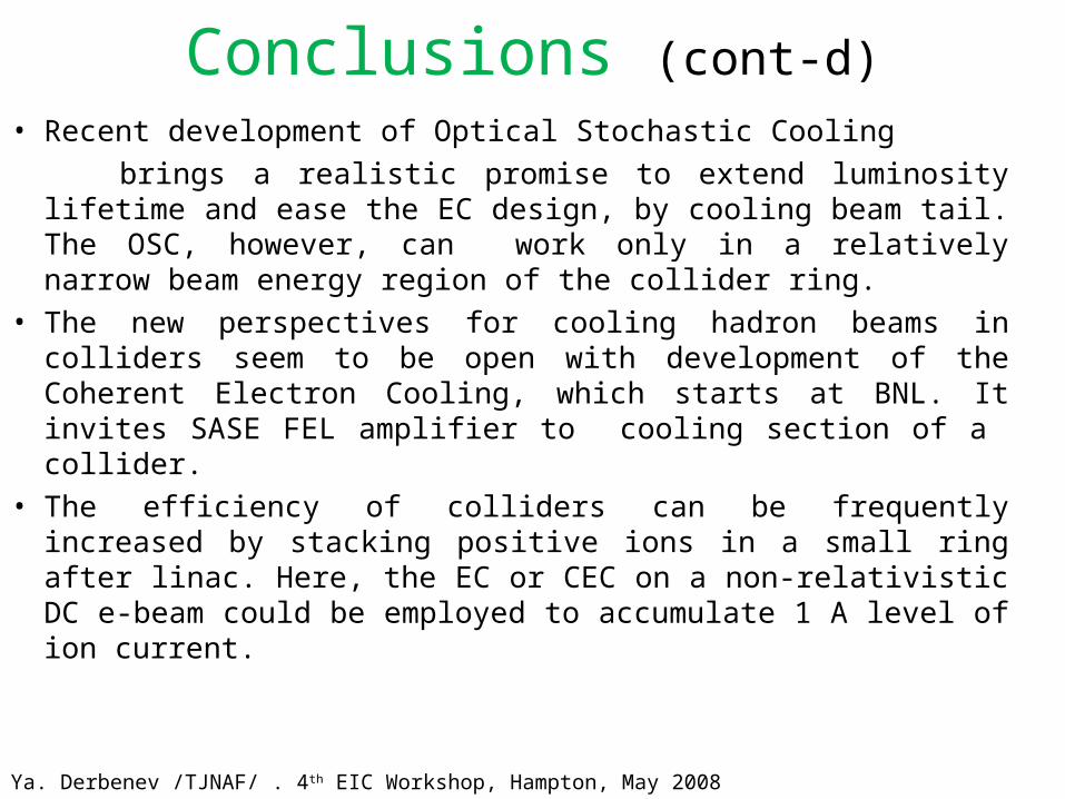
Conclusions (cont-d)
• Recent development of Optical Stochastic Cooling brings a realistic promise to extend luminosity lifetime
and ease the EC design, by cooling beam tail. The OSC, however, can work only in a relatively narrow beam energy region of the collider ring.
• The new perspectives for cooling hadron beams in colliders seem to be open with development of the Coherent Electron Cooling, which starts at BNL. It invites SASE FEL amplifier to cooling section of a collider.
• The efficiency of colliders can be frequently increased by stacking positive ions in a small ring after linac. Here, the EC or CEC on a non-relativistic DC e-beam could be employed to accumulate 1 A level of ion current.
Ya. Derbenev /TJNAF/ . 4th EIC Workshop, Hampton, May 2008

We entering an exciting era of
the new generation of
high luminosity colliding beams
provided by the
Advanced cooling techniques!
Thank you!
Ya. Derbenev /TJNAF/ . 4th EIC Workshop, Hampton, May 2008
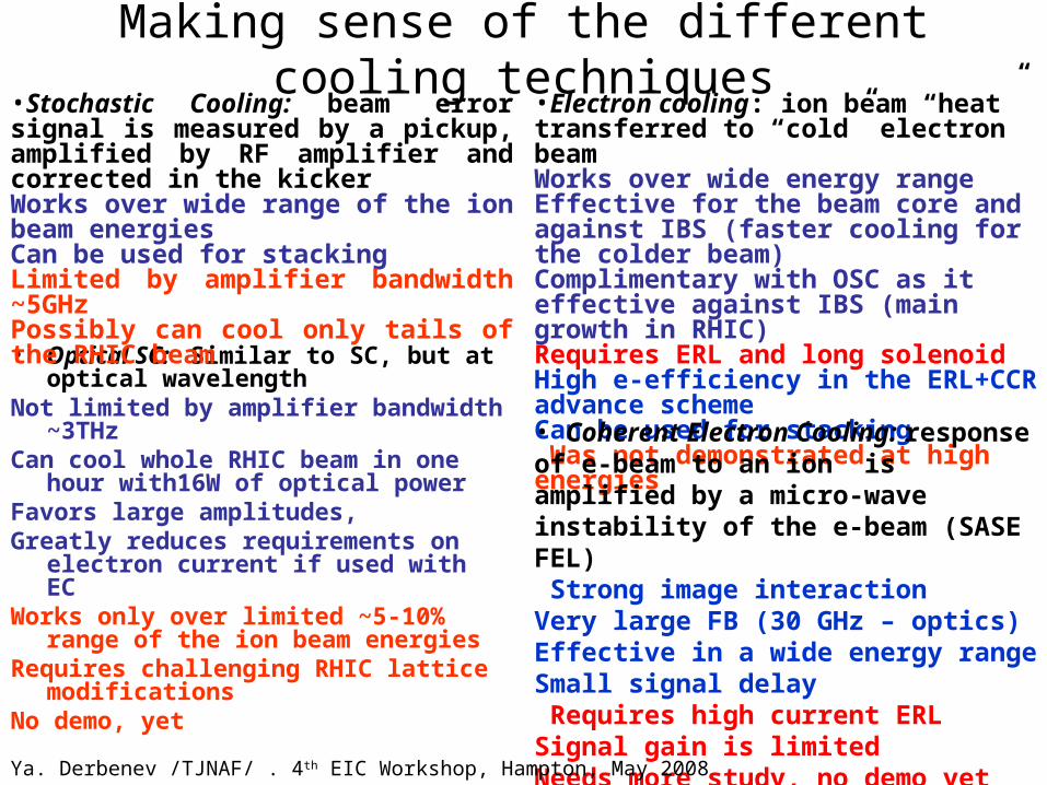
Making sense of the different cooling techniques
• Optical SC: Similar to SC, but at optical wavelength
Not limited by amplifier bandwidth ~3THz
Can cool whole RHIC beam in one hour with16W of optical power
Favors large amplitudes, Greatly reduces requirements on
electron current if used with ECWorks only over limited ~5-10% range
of the ion beam energiesRequires challenging RHIC lattice
modificationsNo demo, yet
•Stochastic Cooling: beam error signal is measured by a pickup, amplified by RF amplifier and corrected in the kickerWorks over wide range of the ion beam energiesCan be used for stackingLimited by amplifier bandwidth ~5GHzPossibly can cool only tails of the RHIC beam
•Electron cooling: ion beam “heat” transferred to “cold” electron beamWorks over wide energy rangeEffective for the beam core and against IBS (faster cooling for the colder beam)Complimentary with OSC as it effective against IBS (main growth in RHIC) Requires ERL and long solenoidHigh e-efficiency in the ERL+CCR advance schemeCan be used for stacking Was not demonstrated at high energies
• Coherent Electron Cooling: response of e-beam to an ion is amplified by a micro-wave instability of the e-beam (SASE FEL) Strong image interactionVery large FB (30 GHz – optics)Effective in a wide energy rangeSmall signal delay Requires high current ERLSignal gain is limitedNeeds more study, no demo yet
Ya. Derbenev /TJNAF/ . 4th EIC Workshop, Hampton, May 2008