Embed Size (px)
Citation preview

P/N: 8505017 ©2016 TJERNLUND PRODUCTS, INC. ALL RIGHTS RESERVED REV. C 02/16
IMPORTANT: This upgraded circuit board features:
A new #6 power LED
Constant red when 115 VAC is supplied to L & N.
A new color for the #2 LED
Constant blue when fan prover safety circuit is closed.
A revised #5 LED
With no call for heat present, flashes 3 seconds on /
3 seconds off if microcontroller is working properly.
LED # 2 now BLUE
(previously GREEN)
New LED # 6 RED
115V power supplied
to UC1 L & N terminals
LED # 5 RED With no
call for heat, flashes 3
seconds on / 3 seconds
off if microcontroller is
working properly.
X.06 VERSION UC1 BOARD FEATURES
LED 1 (AMBER)
LED 2 (BLUE)
LED 3 (GREEN)
LED 4 (RED)
LED 5 (RED)
LED 6 (RED) POWER LED
DRY
24 V
115 V
APPLIANCE
INTERLOCK
RELAY
VENTER
MOTOR
RELAY
A B 1 2 3 4 L N
J1 J2 XL XN
P1 P2 C GND F
(1 9)
N M MTR
It’s easy to convert old power venter installations to our UC1 universal interlock control. Below we show electrical box photos of our dis-
continued HSUL and HST series power venters. We have cross referenced the UC1 terminal strip position typically associated with the
colored wires of either our HSUL or HST series power venters. Example: A call for heat signal that was wired to the blue leads of an old
HSUL series power venter would be reconnected to terminal #1 of the UC1 control. IMPORTANT: Follow all cautions and warnings in
Power Venter or UC1 wiring section for complete details.
If replacing an existing Power Venter or UC1 that includes an X.02 or X.04 version of a UC1 board, the LED lights and sequencing
have changed as outlined in this UC1 Board Version X.06 Update notice. See additional recommendations on back page for model
specific information if replacing an existing Power Venter or UC1 Board.
(UC1 Terminal 1) = HSUL Blue Wires
(UC1 Terminal 2) = HSUL Orange Wire
(UC1 Terminal 4) = HSUL Yellow Wire
(UC1 Terminal 1) = HST Orange and
Blue Wires
(UC1 Terminal 4) = HST Yellow Wire
(UC1 Terminal 2) = HST White Wire
TJERNLUND PRODUCTS, INC.1601 Ninth Street • White Bear Lake, MN 55110-6794
PHONE (800) 255-4208 • (651) 426-2993 • FAX (651) 426-9547
Visit our web site • www.tjernlund.com
CONVERSION TIPS FOR OLD HSUL & HST SERIES POWER VENTERS
IMPORTANT!!! UC1 BOARD VERSION X.06 UPDATES
LED INDICATOR LIGHTS
LED #1 (Amber) Appliance call for heat.
LED #2 (Blue) Safety circuit through P1 & P2 (Venter Fan Prover and/or High Limit). Indicates Venter prover is closed during run cycle.
Burner circuit is energized with Interlock Relay contact closure from terminal 3 to 4.
LED #3 (Green) Power switched to Venter motor from L to MTR & M.
LED #4 (Red) Status / Fault indicator.
LED #5 (Red) Used as a status indicator.
LED #6 (Red) 115 VAC power supplied to board.
LED STATUS INDICATORS
LED #4 & #5 (Red) Flashing Alternately = Venter in Pre-purge. (Pre-Purge options 0, 5, 20, 35 seconds)
LED #4 & #5 (Red) Flashing in Unison = Venter in Post-Purge. (Post-Purge options 0, 30 seconds or 1, 2, 4, 8, 16 minutes)
LED #4 Flashes Continuously* = Fan Prover opened for more than 10 seconds during burner cycle.
(Venter will run for 10 minutes, attempting to make Fan Prover)
LED #5 (Red) Flashing Intermittently = With no call for heat, flashes 3 seconds on / 3 seconds off if microcontroller is working properly.
LED FAULT INDICATORS
Fault conditions are indicated by counting the number of times LED #4 (Red) flashes.
LED #4 Flashes 2 Times Fan Prover was in electrically closed position prior to venter operation.
LED #4 Flashes 3 Times* Fan Prover does not close within 60 seconds after call for heat.
LED #4 Flashes 4 Times* Fan Prover did not re-close after 10 minutes of Venter operation.
LED #4 Flashes 5 Times* Fan Prover opened for more than 10 seconds during burner cycle but closed within 10 minutes.
* Investigate cause of Fan Prover short cycling such as; Firing burner at capacities or temperatures exceeding Venter limits,
excessive vent pipe runs, elbows directly on venter discharge, high winds, plugged / kinked Fan Prover sensing tube or a faulty
Fan Prover switch. In-Forcer model’s intake screen and prefilter, if applicable, should be cleaned if necessary.
CHECKING MEMORY FOR LAST FAULT CODE
IMPORTANT: Prior to accessing the fault code memory, note the settings of the dip switches so that they can be returned to their original Pre /
Post-Purge positions. When power is supplied to the UC1 use caution when moving dip switches.
The last fault code can be retrieved at any time by setting all dip switches 1-8 to the up, or “on” position. The last fault code, or lack there of, will
be indicated by counting the number of times LED 4 flashes. By moving any of the dip switches back to their original position, the fault code will
be cleared. NOTE: The UC1 board must have its 115 VAC power supply present when any of the (1-8) dip switches are moved back to their
original position for the fault code to clear.
IMPORTANT: Fault codes will automatically be displayed after a fault condition occurs. If the call for heat interlock signal
or 115 VAC power is removed, the UC1 board will reset and the fault will be stored in memory instead of displayed. Any
new fault will replace any previous fault.
IMPORTANT:
For 950-8804 UC1 Replacement Board Kits: If this is a 950-8804 UC1 board kit and you are replacing an existing UC1 board with this
new board, note Dip Switch settings on existing UC1 circuit board so that those same settings can be positioned on this replacement circuit
board. NOTE: Adhere appropriate included label over existing label in UC1 or SideShot electrical box. Also adhere "Checking Memory for
Last Fault Code" sticker on inside of UC1 or SideShot SS1 Series electrical box. On SS2 Series adhere to underside of electrical box.
For SideShot Series SS1 Models: The Pre-Cycle Prover Status Check is deactivated from the factory on the SS1 Series. Because of the
low set point of the SS1 Fan Prover (as low as .03" w.c.) cross winds may cause the Fan Prover to close prior to a call for heat. Activating the
Prover Status Check on the SS1 may cause nuisance lockouts. Important: Deactivate the Pre-Cycle Prover status check if installing this board
on a new or existing SS1 installation by pushing the #9 dip switch up or “ON” to disable.
For Draft Inducers with the UC1: Natural draft or winds may be sufficient to close the fan prover switch contacts prior to a call for heat
when using the PS1505 fan prover with a draft inducer. Keeping the Pre-Cycle Prover Status Check activated may cause nuisance lockouts.
Important: Deactivate the Pre-Cycle Prover status check if installing this board on a new or existing draft inducer installation by pushing the #9
dip switch up or “ON” to disable.

Copyright © 2005, Tjernlund Products, Inc. All rights reserved. P/N 8504106
REV. C 07/05
OWNER INSTRUCTIONS, DO NOT DESTROY
Recognize this symbol as an indication of important Safety Information!
NOTE: FLUE GAS TEMPERATURES MUST NOT EXCEED 600OFAT VENT SYSTEM INLET FOR U.S. INSTALLATIONSAND 285OC (550OF) AT VENT SYSTEM INLET FOR CANADIAN INSTALLATIONS.
THESE INSTRUCTIONS ARE INTENDED AS AN AID TO QUALIFIED, LICENSEDSERVICE PERSONNEL FOR PROPER INSTALLATION, ADJUSTMENT AND OPERA-TION OF THIS UNIT. READ THESE INSTRUCTIONS THOROUGHLY BEFOREATTEMPTING INSTALLATION OR OPERATION. FAILURE TO FOLLOW THESEINSTRUCTIONS MAY RESULT IN IMPROPER INSTALLATION, ADJUSTMENT, SER-VICE OR MAINTENANCE POSSIBLY RESULTING IN FIRE, ELECTRICAL SHOCK,CARBON MONOXIDE POISONING, EXPLOSION, OR PERSONAL INJURY ORPROPERTY DAMAGE.
!
DO NOT DESTROY. PLEASE READ CAREFULLY AND KEEP INA SAFE PLACE ON JOB SITE FOR FUTURE REFERENCE.
MODELSHSJ HS1 HS2
FOR NATURAL GAS, LP OR OIL
TJERNLUND PRODUCTS, INC.1601 Ninth Street • White Bear Lake, MN 55110-6794PHONE (800) 255-4208 • (651) 426-2993 • FAX (651) 426-9547Visit our web site • www.tjernlund.com
INCLUDES UC1 UNIVERSAL CONTROL
UC1 VERSION X.06

Address all correspondence to:Customer Service • Tjernlund Products, Inc. • 1601 Ninth Street • White Bear Lake, MN 55110-6794Call us toll free at 800-255-4208, visit our web site @ www.tjernlund.com or email us at [email protected].
TABLE OF CONTENTS
PAGE(S)SIZING TABLES AND SPECIFICATIONS ..................................................................................................................................... 1 - 2INSTALLATION RESTRICTIONS.......................................................................................................................................................... 2CAUTIONS....................................................................................................................................................................................... 2 - 3GENERAL INFORMATION.................................................................................................................................................................... 3SAFETY INSPECTION OF PREVIOUSLY USED APPLIANCE............................................................................................................ 3UC1 UNIVERSAL CONTROL BOARD FEATURES ..............................................................................................................................4LED STATUS / FAULT INDICATORS AND FAULT RETRIEVAL FROM MEMORY ...........................................................................4, 5PRE / POST-PURGE & PRE-CYCLE PROVER STATUS CHECK SETTINGS.................................................................................5, 6INSTALLATION ..................................................................................................................................................................................... 6
VENT SYSTEM TERMINATION U.S. INSTALLATIONS ....................................................................................................... 6VENT SYSTEM TERMINATION CANADIAN INSTALLATIONS ........................................................................................... 7
POWER VENTER INSTALLATION ...................................................................................................................................................... 7CODE REQUIREMENTS .......................................................................................................................................................7INSTALLATION RESTRICTIONS.......................................................................................................................................... 8POWER VENTER MOUNTING............................................................................................................................................. 9DRAFT CONTROL INSTALLATION ON AN INDUCED DRAFT GAS APPLIANCE...................................................... 9 - 10
UC1 UNIVERSAL CONTROL INSTALLATION ................................................................................................................................... 10ELECTRICAL WIRING .........................................................................................................................................................................10
WARNINGS, SEQUENCE OF OPERATION & INTERNAL SCHEMATIC ...................................................................10 - 11UC1 WIRING CONNECTIONS TO VENTER GROUND, MOTOR AND PROVER LEADS ................................................11MULTIPLE OR MILLIVOLT APPLIANCE INTERLOCKS .....................................................................................................11UC1 WIRING TO GAS FIRED APPLIANCE ................................................................................................................12 - 14UC1 WIRING TO OIL FIRED EQUIPMENT .................................................................................................................14 -16
UC1 OPERATION CHECK, DRAFT CHECK, SAFETY INTERLOCK / COMBUSTION AIR TEST..............................................16 - 17MAINTENANCE .................................................................................................................................................................................. 18TROUBLESHOOTING ..................................................................................................................................................................18 - 19WARRANTY & REPLACEMENT PARTS .............................................................................................................................................19
VENTER SPECIFICATIONS
1
HS-SERIES MODEL SELECTION TABLE POWER VENTER DIMENSIONS
IMPORTANTTable footage is based on equivalent vent pipe length. To calculateequivalent vent pipe length, add the straight vent pipe plus 10’ forevery 90O elbow and 5’ for every 45O elbow.
If venting multiple appliances with one Power Venter, the total com-bined BTU/hr. input of all appliances must be added together to sizethe Power Venter.
60
60
60
3000 95 1.26 YES
953000 YES1.26
2243000 YES1.51
MODEL CONTROLMOTOR Hz R.P.M. WATTS AMPS THERMAL
115 24/115/DRYHSJ
24/115/DRY115
24/115/DRY115
HS1
HS2
VOLTAGEVOLTAGE PROTEC.
2001018H
The UC1 Universal Control may be interlocked with DryContact, 24 VAC or 115 VAC heater control circuits.

UC1 UNIVERSAL CONTROL SPECIFICATIONS
INSTALLATION RESTRICTIONS
1. This device must be installed by a qualified professional installer in accordance with these instructions. If improperly installed, a hazardous condition such as explosion or carbon monoxide poisoning could result.
2. Do not install the Power Venter on incinerators, incinerating toilets, condensing type appliances or solid-fuel burning appliances.
3. The Power Venter shall only be installed on Natural Gas, LP or Oil-fired appliances.
4. Do not install the Power Venter on an appliance with an automatic valve having a manual opener unless the manual opener has been rendered inoperative or the automatic valve has been replaced with a valve not equipped with a manual opener.
5. The Power Venter may only be installed on appliances equipped with a draft hood, draft diverter or barometric draft control.
6. The Power Venter shall not be installed where flue gas temperatures exceed 6000 F. at Power Venter inlet for U.S. or 2850 C (5500 F) for Canadian installations.
FLUE GAS TEMPERATURE VERIFICATION:A) Consult appliance manufacturer for temperature of gases at the appliance outlet after dilution by draft hood, draft diverter or baro-
metric draft control.AND
B) Measure temperature of flue gases at the Power Venter inlet at time of installation. Temperature should be measured after appliance and Power Venter have operated for at least 15 minutes, allowing flue gas temperature to stabilize.
Flue gas temperature at Power Venter inlet must not exceed 6000 F. for U.S. or 2850 C (5500 F) for Canadian installations.
7. The appliance(s) may only be installed on the suction side of Power Venter.
8. The UC1 is intended for indoor installation only. Do not mount the UC1 junction box on a heat source that exceeds 140oF. Examples of improper mounting surfaces include vent pipe, top of heater casing or any place where radiant or convective heat would cause the junction box temperature to exceed 140oF (60oC).
CAUTIONS
The Power Venter must be installed by a qualified installer in accordance with these instructions and all local codes or in theirabsence in accordance with the latest edition of The National Fuel Gas Code (ANSI Z223.1/NFPA #54), NFPA # 31 Oil BurningEquipment, the latest edition of the National Electrical Code (NFPA#70) and the Occupational Safety and Health Act (OSHA) whenapplicable. Canadian installations must comply with The Natural Gas Installation Code (CAN/CGA-B149.1); Propane InstallationCode (CAN/CGA-B149.2); Installation Code For Oil Burning Equipment (CAN/CSA-B139). Improper installation can create a haz-ardous condition such as an explosion, fire, electrical shock or carbon monoxide poisoning resulting in property damage, personalinjury or death. “Qualified Installer” shall mean an individual properly trained and licensed in accordance with local codes.
2
Improper installation, adjustment, alterations, service or maintenance can cause injury or property damage. Refer to this manual.For assistance or additional information consult a qualified installer, service agency, gas or oil supplier.
POWERREQUIREMENTS
EXTERNALPOWER SWITCHING
CAPACITY
J1 / J2JUMPER
SAFETYCIRCUIT
ADD VENTER MOTORLOAD PLUS 1/2 AMP
FOR UC1 LOAD
EXTERNALCALL TRIGGER
METHODS
J1 / J2
P1 / P2
L / N
3 TO 4
T-BLOCK
T-BLOCK
(RELAY K1)
XL / XN
UC1 CONTROL
M & MTR(RELAY K2)
T-BLOCKA / B
24V1 / 2
115V1 / 2
OR
OR
USED TO JUMP CALL HOT (24 VAC) OR CALL LINE (115 VAC) FROM TERMINAL 1 TO TERMINAL 3.
CONNECTED TO FAN PROVER.1 mA @ 5 VDC. DO NOT SUPPLY POWER HERE.
REMOVE J1-J2 JUMPER IF A DIFFERENT VOLTAGE SOURCE IS PROVIDED TO TERMINAL 3.
120 VAC ±10 %, 50/60 Hz
MOTOR - 1 H.P. MAX. @ 120 VAC, 50/60 Hz
USER-PROVIDED 24 VAC AT TERMINALS 1 & 2. 1 = CALL HOT, 2 = COMMON. CONTROLREQUIRES 5 mA @ 24 VAC TO TRIGGER. MOVE RED VOLTAGE JUMPER TO "24V" LOCATION.
3 mA @ 5 VDC. MOVE RED VOLTAGE JUMPER TO "DRY" LOCATION. DO NOT SUPPLY POWER.USER-PROVIDED CONTACT CLOSURE FROM A TO B. SIZE CONTACT CLOSURE TO HANDLE
GENERAL PURPOSE - 15A @ 120 VAC, 50/60 Hz
DURING OPERATION THE CONTROL USES 50 mA MAX @ 120 VAC
MOTOR - 1 H.P. MAX. @ 120 VAC, 50/60 Hz
150 mA MAX @ 120 VAC, 50/60 HzCAN ONLY BE CONNECTED TO TJERNLUND-SPECIFIED AUXILIARY DEVICE
CIRCUIT PROTECTION PROVIDED BY INSTALLER
GENERAL PURPOSE - 15A @ 120 VAC, 50/60 Hz
RESISTIVE - 10A @ 28 VDC PILOT DUTY - 470 VA
USER-PROVIDED 115 VAC AT TERMINALS 1 & 2. 1 = CALL LINE, 2 = NEUTRAL. CONTROLREQUIRES 1 mA @ 115 VAC TO TRIGGER. MOVE RED VOLTAGE JUMPER TO "115V" LOCATION.
D/N 9183006H

Failure to install, maintain and/or operate the Power Venter in accordance with manufacturer's instructions may result in conditionswhich can produce bodily injury and property damage.
Disconnect power supply from the UC1 and heating equipment when making wiring connections and servicing the Venter. Failure todo so may result in personal injury and/or equipment damage. LED #6 (RED) should be off with power removed.
1. In order to comply with the ETL Listing of the Power Venters the Fan Prover must be wired with the appliance so as to prevent the main burner(s) from firing if the Power Venter malfunctions or the flue is blocked. It is not safe to use the Power Venter as is on millivolt appliances, such as water heaters which employ a combination gas valve/temperature controller, since the Fan Prover can not be wired as described in this manual. Millivolt appliances require additional interlock controls such as our WHKE kit. See millivolt wiring diagram in this manual for more details.
2. Plan the vent system so that Code required distances are maintained from plumbing and wiring.
3. The Power Venter motor shaft must be mounted horizontally to ensure proper operation of the Fan Proving Switch and prevent motor bearing wear.
4. Make certain the power supply is adequate for the fan motor and UC1 requirements. Do not add the Power Venter to a circuit where the total load is unknown.
5. The installer must verify that the BTU/hr. input of the appliance does not exceed the recommended input of the Power Venter. See selection table on page 1 of these instructions for sizing information.
6. Flue gas temperatures must not exceed 6000 F. at the Power Venter inlet for U.S. installations and 2850 C (5500 F) for Canadian installations. Ambient temperatures surrounding Power Venter must not exceed 400 C (1040 F). See “Flue Gas Temperature Verification”, on page 2.
7. “Safety Inspection Of a Previously Used Appliance”, below, must be performed before installation on previously used equipment.
GENERAL INFORMATION
These units have been factory tested and rated in accordance with AMCA standard 210, Test Code for Air Moving Devices.
Each Power Venter and UC1 is electrically factory line tested before shipment.
After opening carton, inspect thoroughly for hidden damage. Wheel should rotate freely. If any damage is found notify freight carrierand your distributor immediately and file a concealed damage claim.
IMPORTANTWe do not recommend using the model HSJ for oil fired equipment since the small blower wheel is more susceptible to soot buildup.We recommend using the SideShot Series for oil inputs under 1 GPH (142,000 BTU/hr.) firing rates.
*SAFETY INSPECTION OF A PREVIOUSLY USED APPLIANCE
(Perform prior to Power Venter installation)
The following procedure is intended as a guide to aid in determining that an appliance is properly installed and is in safe condition forcontinuing use. This procedure is based on central furnace and boiler installations and it should be recognized that generalized pro-cedures cannot anticipate all situations. Accordingly, in some cases deviation from this procedure may be necessary to determinesafe operation of the equipment.
a. This procedure should be performed prior to any attempt at modifications of the appliance or installation of the Venter.
b. If it is determined there is a condition which could result in an unsafe operation, the appliance should be shut off and the owner advised of the unsafe condition.
The following steps should be followed in making the safety inspection:1. Visually inspect the venting system and determine there is no blockage or restriction, leakage, corrosion or other deficiencies
which could cause an unsafe condition.2a. Oil Installations: Inspect burner and primary control for proper operation.
2b. Gas Installations: Conduct a gas leakage test of the appliance piping and control system downstream of the shutoff valve in the supply line to the appliance.Inspect burners and cross overs for blockage and corrosion.
3. Applicable only to furnaces: Inspect heat exchanger for cracks, openings or excessive corrosion. Check both the limit control and fan control for proper operation.
4. Applicable only to boilers: Inspect for evidence of water or combustion product leaks. Determine that the water pumps are in operating condition. Test low water cutoffs, automatic feed controls, pressure and temperature limit controls and relief valves in accordance with the manufacturer's recommendations to determine that they are in operating order.
* Excerpts from the National Fuel Gas Code (ANSI Z223.1/NFPA #54), Appendix H.
3

UC1 UNIVERSAL CONTROL BOARD FEATURES
# 1. Power supplied by board. Do not supply power to this area or control damage may result.# 2. Do not supply power to the appliance interlock block with the call selector in the “DRY” position.
Control damage may result if power is supplied.# 3. Circuit protection must be provided by the installer. 16 Amps is the maximum current allowed for this device at terminal L.
A 15 Amp circuit breaker is recommended.VETIILED STATUS & FAULT INDICATORS
LED INDICATOR LIGHTS LED #1 (Amber) Appliance call for heat.LED #2 (Blue) Safety circuit through P1 & P2 (Venter Fan Prover). Indicates Venter prover is closed during run cycle.
Burner circuit is energized with Interlock Relay contact closure from terminal 3 to 4. LED #3 (Green) Power switched to Venter motor from L to MTR & M.LED #4 (Red) Status / Fault indicator.LED #5 (Red) Used as a status indicator.LED #6 (Red) 115 VAC power supplied to board.
LED STATUS INDICATORSLED #4 & #5 (Red) Flashing Alternately = Venter in Pre-purge. (Pre-Purge options 0, 5, 20, 35 seconds)LED #4 & #5 (Red) Flashing in Unison = Venter in Post-Purge. (Post-Purge options 0, 30 seconds or 1, 2, 4, 8, 16 minutes)LED #4 (Red) Flashing Continuously* = Fan Prover opened for more than 10 seconds during burner cycle.
(Venter will run for 10 minutes, attempting to make Fan Prover)LED #5 (Red) Flashing Intermittently = With no call for heat, flashes 3 seconds on / 3 seconds off if microcontroller is working properly.
4
LED 1 (AMBER)LED 2 (BLUE)LED 3 (GREEN)LED 4 (RED)LED 5 (RED)
LED 6 (RED) POWER LED
DRY
24 V
115 V
APPLIANCEINTERLOCK
RELAY
VENTERMOTORRELAY
A B 1 2 3 4 L N
J1 J2 XL XN
P1 P2 C GND F
(1 9)
N M MTR
APPLIANCE INTERLOCKRELAY1 HP MAX LOAD across terminals 3 & 4.
VENTER MOTOR RELAY1 HP MAX LOAD from terminals L to MTR & M.
XL / XN AUXILIARY DEVICE POWER TERMINALS 115 VAC - Maximum of 0.15 Amps.Only connect to Tjernlund auxiliary devices.SEE WARNING # 1.
MTR & M / N LOAD TERMINALS FROM VENTER MOTOR RELAYUsed to drive Venter Motor. 1 HP MAX LOAD across terminals MTR & M / N.
L / N - 115 VAC POWER SUPPLY BLOCK115 VAC / 50-60 HzCircuit protection provided by installer.SEE WARNING # 3.
APPLIANCE INTERLOCK TERMINAL BLOCK (A-B, 1-4)A - B - Dry Contact call. 3 mA @ 5VDC.
SEE WARNING # 1.1 - 24 or 115 VAC intercepted call.
IMPORTANT: RED voltage jumper must match intercepted call voltage.
2 - 24V common or 115V Neutral.3 - Common terminal to appliance relay con-
tacts. IMPORTANT: J1-J2 jumper routes call voltage at terminal 1 to 3. Remove J1-J2 jumper if a different voltage source is provided to terminal 3.
4 - Normally open terminal of appliance relay. Will be energized from terminal 3 if safety circuit is “proven”.
J1- J2 CALLJUMPERUsed when the call signal isused as the “proven” returnsignal to the appliance. Seewiring section for details.
APPLIANCE CALLVOLTAGE SELECTION
Place RED voltage jumper inproper location based onappliance call interlock volt-age. SEE WARNING # 2.
IMPORTANT
LED STATUS LIGHTSSee “LED Status & FaultIndicator Section” for details.
DIP SWITCH SETTINGSPre-Purge (1-2)Post-Purge (3-8) Prover status check (9)See “Pre / Post Purge &Prover Status Check DipSwitch Settings”.
P1 - P2 SAFETY CIRCUITTERMINALS1 mA @ 5VDC.SEE WARNING # 1.
C, GND, F AUXILIARY DEVICE COMMUNICATION TERMINALS2 mA @ 5VDC. For Tjernlund MAC1E or MAC4E auxiliary devices. SEE WARNING # 1.

LED FAULT INDICATORS Fault conditions are indicated by counting the number of times LED #4 (Red) flashes.LED #4 Flashes 2 Times Fan Prover was in electrically closed position prior to venter operation.LED #4 Flashes 3 Times* Fan Prover does not close within 60 seconds after call for heat.LED #4 Flashes 4 Times* Fan Prover did not re-close after 10 minutes of Venter operation.LED #4 Flashes 5 Times* Fan Prover opened for more than 10 seconds during burner cycle but closed within 10 minutes.
* Investigate causes of Fan Prover not making, i.e; Firing burner at capacities or temperatures exceeding Venter limits, excessive vent pipe runs, elbows directly on venter discharge, high winds, plugged / kinked Fan Prover sensing tube or a faulty Fan Prover.
CHECKING MEMORY FOR LAST FAULT CODE IMPORTANT: Prior to accessing the fault code memory, note the settings of the dip switches so that they can be returned to theiroriginal Pre / Post-Purge positions. When power is supplied to the UC1 use caution when moving dip switches.The last fault code can be retrieved at any time by setting all dip switches 1-8 to the up, or “on” position. The last fault code, or lackthere of, will be indicated by counting the number of times LED 4 flashes. By moving any of the dip switches back to their originalposition, the fault code will be cleared. NOTE: The UC1 board must have its 115 VAC power supply present when any of the (1-8) dipswitches are moved back to their original position for the fault code to clear.
PRE / POST PURGE AND PROVER STATUS CHECK DIP SWITCH SETTINGS
Remove power to UC1 and heating equipment when installing, servicing or changing dip switch settings. Failure to do so may result in personal injury and/or equipment damage. LED #6 (RED) should not be on if 115 VAC supply power is removed from the control.Pre-purge Used for a Venter with longer vent runs to get draft fully established throughout the vent system prior to burner ignition. Also benefi-cial for negative pressure prone environments. IMPORTANT: Nuisance equipment lockouts may occur if Venter pre-purge is runningin conjunction with and is longer than any equipment timing circuit. Pre-purge settings must be shorter than burner control lockouttime unless wired prior to burner control timing circuit (i.e. aquastat / thermostat).Post-purgeA Venter post-purge has been factory set at 2 minutes. Confirm that dip switch #5 is in the up or "on" position. Oil fired equipmentrequires that the post-purge be long enough to eliminate post cycle nozzle drip odor. A longer post-purge may be necessary for longervent runs or high heat retention, refractory lined combustion chambers. A shorter post-purge may be desired for gas installations.
IMPORTANT: Fault codes will automatically be displayed after a fault condition occurs. If the call for heat interlock signalor 115 VAC power is removed, the UC1 board will reset and the fault will be stored in memory instead of displayed. Anynew fault will replace any previous fault.
5
Pre-Purge Post-Purge
Pre-Cycle FanProver Status Check Activated
DIP SWITCH NUMBERING
1ON
ON
POST-PURGE SETTINGS (SEE “POST-PURGE” ABOVE PRIOR TO SETTING)
ON
2 3 4 5 6 7 8 9
43 4865 7 3 5 6 7 8 3 4 5 6 7 8 3 754 6 8
43 4865 7 3 5 6 7 8 3 4 5 6 7 84 Minutes 8 Minutes 16 Minutes
1 Minute0 Seconds 30 Seconds 2 Minutes
ON
PRE-PURGE SETTINGS (SEE “PRE-PURGE” ABOVE PRIOR TO SETTING)
1 2 1 2 1 2 1 20 Seconds 5 Seconds 20 Seconds 35 Seconds
LED 1 AMBERLED 2 BLUELED 3 GREENLED 4 REDLED 5 RED
LED 6 REDPOWER LED
ON1 9

INSTALLATION
VENT SYSTEM TERMINATION
Before installing Power Venter determine location of vent system termination.
TOOLS REQUIRED• Saber Saw or Cement Drill • Drill • 1/8” and 1/4” Drill Bits• Wood or Masonry Chisel • Blade Screwdriver or 1/4” Nut Driver • Wire Cutter/Stripper
NOTE: Termination of a Side Wall Vent System with a device other than the Tjernlund VH1 Series Vent Hood could affect system performance and result in a possible safety hazard. Consult Vent Hood instructions for complete installation details.
VENT HOOD TERMINATION CODE REQUIREMENTS FOR U.S. INSTALLATIONS
If possible, locate the Vent Hood on a wall that does not face the direction of prevailing winds. This will diminish the possi-bility of appliance interruption during periods of extreme winds and prevent oil odors caused by backdrafts.
If possible, locate the Vent Hood no closer than 3 feet from an inside corner of an L-shaped structure.
Terminate the vent system so that proper minimum clearances are maintained as cited in the latest edition of the National Fuel GasCode (NFPA # 54) and the latest edition of NFPA #211, or as follows:
• Not be less than 7 feet above grade when located adjacent to public walk ways.• At least 3 feet above any forced air inlet located within 10 feet.• At least 4 feet below, 4 feet horizontally from or 1 foot above any door, window or gravity air inlet into any building. • At least 12 inches above grade.• So that the flue gases are not directed so as to jeopardize people, overheat combustible structures or enter buildings, and• Not less than 2 feet from an adjacent building.
6
For oil installations do not terminate HS-Series Power Venters on vinyl siding because temperatures can easily exceed 1500F.The SideShot® is the only Tjernlund Power Venter recommended for termination on vinyl siding when using oil.
P1 & P2 PRE-CYCLE FAN PROVER STATUS CHECK
The Pre-Cycle Prover Status Check is activated from the factory. When activated the UC1Universal Control checks across P1 & P2 safety circuit (Venter Fan Prover) to verify that the FanProver switch is “Open” upon a call for heat and not stuck “Closed”.
Pre-CycleProver StatusCheck Activated 9

VENT HOOD TERMINATION CODE REQUIREMENTS FOR CANADIAN INSTALLATIONS
If possible, locate the Vent Hood on a wall that does not face the direction of prevailing winds. This will diminish the possibility of appliance interruption during periods of extreme winds and prevent oil odors caused by backdrafts.N
TER• A venting system shall not terminate underneath a veranda, porch, or deck, or above a paved sidewalk or a paved driveway that is
located between two buildings, and that serves both buildings.• The exit terminals of mechanical draft systems shall not be less than 2.13m (7ft) above grade when located adjacent to a paved
sidewalk or driveway.• A venting system shall not direct flue gases towards brickwork, siding, or other construction, in such a manner that may cause
damage from heat or condensate from the flue gases.• A vent system shall not direct flue gases so as to jeopardize people, overheat combustible structures, or enter buildings.
A venting system shall not terminate within 1.8 m (6ft) of the following:• A window, door or mechanical air supply inlet of any building, including soffit openings• A gas service regulator vent outlet• A combustion air inlet • A property line• A direction facing combustible materials or openings of surrounding buildings
A venting system shall not terminate within 1m (3ft) of the following:• Above a gas meter/regulator assembly within 1m (3ft) horizontally of the vertical centreline of the regulator• A oil tank or an oil tankfill inlet• The inside corner of an L-shaped structure
A venting system shall not terminate within .3m (1ft) of the following:• Above grade level or any surface that may support snow, ice, or debris
POWER VENTER INSTALLATION
VERIFY POWER VENTER MODEL SELECTION USING TABLES ON PAGE 1.
CODE REQUIREMENTS
All Power Venter installations must follow the appropriate U.S. or Canadian requirements listed under the Installation Restrictions andCautions of this manual.
• All portions of the vent system under positive pressure during operation (on the outlet side of Power Venter) shall be designed and installed so as to prevent leakage of flue or vent gases into the building.
• All appliances must enter the vent system on the inlet side of the Power Venter.
• Provision shall be made to interlock the appliance(s) to prevent the flow of gas to the main burners when the draft system is not performing so as to satisfy the operating requirements of the equipment for safe performance. See “Electrical Wiring” section of this manual for details.
7

INSTALLATION RESTRICTIONS
1. Power Venter must be installed as close as possible to the termination of the vent system to obtain optimal appliance efficiency and to prevent flue gas leakage, (See Diagram A).
2. The Power Venter may be mounted in any position as long as the shaft of the motor remains horizontal, to prevent motor bearing wear and to ensure proper Fan Proving Switch operation,(See Diagram B).
3. The Power Venter housing is single wall. A 6” (15.2 CM) clearance to combustibles must be maintained for gas and 18” (45.7 CM) clear-ance for oil applications, (See Diagram C). If the appliance nameplate specifies a vent connector clearance greater than 6 inches, the greater clearance must be used. Verify these clearances are in compliance with all local codes.
NOTE: Clearance to combustibles may be reduced. Please refer to Clearance Table VI in NFPA #54 or your local code authority.
4. Vent pipe transitions, where necessary, must be gradually tapered, (See Diagram D).
5. Power Venter to vent pipe connections and all joints on the outlet side of the Power Venter must be sealed with high-temperature silicone sealant or aluminum vent pipe tape to prevent flue gas leakage, (See Diagram E).
6. Oil installations require the use of a barometric draft control. Draft control must be installed between the appliance outlet and the Power Venter inlet, (See Diagram E). Oil installations should use the same diameter pipe on the inlet and discharge side of the Power Venter.
7. Allow for a minimum straight section of pipe equal to 3 times the diameter of the vent pipe being used when installing elbows on the discharge side of the Power Venter. For example, if using 4” pipe, allow for 12” of straight pipe before using an elbow, (See Diagram F).
8
DIAGRAM A
DIAGRAM B
DIAGRAM D
DIAGRAM E
ELBOW
PIPE
BEFORE ELBOWSECTION OF PIPEADD A STRAIGHT
VENT PIPE
DIAMETER3 TIMES
2201018D
DIAGRAM F
DIAGRAM C

9
POWER VENTER MOUNTING
1. Slide the outlet of the Power Venter over the inner sleeve of the Vent Hood and connect them together using a tapered transition fitting if necessary, (See Diagram G). If you are unable to make a direct connection to the Vent Hood, vent pipe may be installed between the Power Venter and Vent Hood. However, all vent pipe connections after the Power Venter must be sealed with high temperature silicone caulk or aluminum vent pipe tape to prevent flue gas leakage, (See Diagram E).
2. To facilitate installation and reduce vibration we have included 2 mounting brackets, 2 rubber isolaters and 2 rubber grommets. Oneof the brackets may be used temporarily as a “third hand” while positioning it for permanent installation.
3. When installing the Power Venter for horizontal mount, install one of the brackets to the electrical box using the nut/screw provided. Install the other to the damper rod as shown below. When installing the Power Venter for vertical mount, only one bracket is needed. This bracket should be mounted to the motor as shown below. Temporarily support the Power Venter using wire or a ladder and assemble the mounting brackets, (See Diagram H).
4. Verify required vent pipe diameter from “HS-Series Model Selection” on page 1. Verify that a full sized barometric control has beeninstalled on appliances not equipped with a draft hood or draft diverter.
5. Install properly sized vent pipe sections from Power Venter inlet to appliance outlet avoiding elbows wherever possible, using only tapered transitions. In most cases a reduction in vent pipe diameter from that of the appliance flue outlet will be necessary.
6. Using four holes as guides, attach vent pipe to Power Venter inlet collar using sheet metal screws.
7. Support vent pipe in accordance with vent pipe manufacturer’s instructions.
8. All necessary vent pipe connections after the Power Venter will be under positive pressure during operation. These connections must be sealed with high-temperature silicone sealant or aluminum vent pipe tape supplied by the installer, (See Diagram E).
FURNACEPOWER VENTER ON INDUCED DRAFT GAS APPLIANCES
When installing the Power Venter on induced draft gas appliances, a barometric draft control must be added. The draft control pro-vides pressure relief to neutralize over-drafting and allows a means of draft adjustment for optimum burner efficiency. By adjustingthe draft control and Power Venter damper the installer can obtain the appliance manufacturer’s recommended draft setting.
Install the vent pipe and draft control as shown in the diagrams below. The draft control should connect to a tee off of the applianceflue outlet. The Power Venter may only be used with appliances capable of being chimney vented. It is not suitable for use on high-efficiency, condensing models.
DIAGRAM HDIAGRAM G
(DOWNFLOW APPLIANCE)

UC1 UNIVERSAL CONTROL INSTALLATION AND MOUNTING
The UC1 has a 2 foot whip that contains a ground lead and the leads to power the Venter motor and connect to the Fan Prover. If itis desirable to mount the UC1 more than 2 feet from the Venter an additional electrical junction box and appropriate length of conduitwill be necessary. Any added wire should be 14 gauge and a pig tail should be added to each ground wire connection so that eachelectrical junction box is grounded.
Do not mount the UC1 junction box on a heat source that exceeds 140oF (60oC). Examples of improper mounting surfaces includevent pipe, top of heater casing or any place where radiant or convective heat would cause the junction box temperature to exceed 140oF.
The UC1 is intended for indoor installation only.
Using the key hole slots on the back of the UC1 junction box as a template, mark 4 holes on the mounting surface, drill pilot holes ifnecessary, and secure junction box using provided screws.
ELECTRICAL WIRING
All wiring from the UC1 to the appliance must be appropriate Class 1 wiring as follows: installed in rigid metal conduit, intermediate metalconduit, rigid non-metallic conduit, electrical metallic tubing, Type MI Cable, Type MC Cable, or be otherwise suitably protectedfrom physical damage.
SEQUENCE OF OPERATION WITH UC1 UNIVERSAL CONTROL AND 24 VAC OR 115 VAC HEATER CONTROL CIRCUIT:
Control signal from thermostat, aquastat, primary control or gas valve is intercepted and routed to terminal “1” on UC1 terminal strip.When terminal “1” is energized with either 24 VAC or 115 VAC, the Venter motor is energized. After draft is established, the FanProving Switch closes within 5 to 10 seconds energizing terminal “4”, which completes the circuit allowing burner to fire. NOTE: If aVenter pre-purge is selected, the burner will not fire until the pre-purge time is finished. The Venter will continue to run after the burn-er has finished firing for the set post-purge time cycle. The UC1 is set for a 2 minute post-purge time period from the factory. See“Pre / Post-Purge Settings” on page 5 for details.
The "1" input terminal on the UC1 can accept either a 24 VAC or 115 VAC control signal. IMPORTANT: The RED voltagejumper must be positioned based on appliance interlock voltage 24V or 115V. If using the “DRY” contact activation method, use ter-minals A & B on UC1 control and position the RED voltage jumper tab in the “DRY” position. See millivolt appliance interlock dia-gram for further information. IMPORTANT: Only one interlock method (i.e. 24V, 115V or “Dry”) can be used with the UC1. Multipleappliance interlocks require the use of our MAC-Series multiple appliance controls.
The steps listed under each diagram are intended as a supplement to the diagram. Wiring colors or designations may vary by manu-facturer. If you are unable to wire the UC1 as outlined in these instructions, call Tjernlund’s Customer Service Department toll free at1-800-255-4208 for assistance.
IMPORTANT: If the call for heat interlock signal or 115 VAC power is removed, the UC1 board will reset and any fault, if present, willbe stored in memory instead of displayed. See page 5, “Checking Memory for Last Fault Code”.
10
(UPFLOW APPLIANCE)
IMPORTANT: MORE THAN ONE INTERLOCK METHOD MAY BE APPLICABLE In many cases it is easier to interlock with the thermostat/aquastat portion of the heater control circuit vs. the ignition module /primary control portion of the heater control circuit. Review all of the wiring diagram options prior to choosing the best method.

11
SUPPLY
50/60 Hz115 VAC
NEUTRAL
LINE / HOTCOMMON /
CALL SWITCHUSER-PROVIDED
INTERCEPTEDCALL FOR
APPROVED CALL
OR
HEAT
"DRY"
VENTER MOTOR1 H.P. MAX @ 115 VAC
K2
MOTOR
COMMN
XN
NO K1
INTERLOCKRELAY
J1 COM
J2 JUMPERCALL
GR
EEN
RED
RED
AMBER
BLUE
MAC1E OR MAC4E
PROVER
DEVICES. DO NOTCONNECT POWER
WILL DAMAGE THEOR F. DOING SOTO P1, P2, C, GND
FOR TJERNLUNDG
ND8
9
F
CONTROL.
AUXILIARY3
42
67
5
C
1
P1ON
P2
AS APPLIANCE INTERLOCK VOLTAGE.RED JUMPER POSITION MUST BE THE SAME
DO NOT SUPPLY VOLTAGETO "A" OR "B".
IMPORTANT:
LED3LED5 LED4 LED2 LED1 LED6
24 OR 115 VAC
APPROVED CALL BACK TO HEATER
INTERCEPTED CALL COMMON OR NEUTRAL
24 OR 115 VAC INTERCEPTED CALL FOR HEAT
5 VDC BOARD-GENERATED POWERDO NOT SUPPLY POWER!
115 VAC
LEGEND:
TERMINAL 2:
TERMINAL 1:
TERMINAL 4:
FIGURE 1303958-1C
LEDPO
WER
RED
DR
Y
24V
115V
(1 - 2)PRE-PURGE SETTINGS
(3 - 8)
(9)OPEN PROVER OPTION
POST-PURGE SETTINGS
RELAYMTR NO
INC
.
9183006TJE
RN
LUN
DP
RO
DU
CTS
,R
XL
WARNING: Disconnect power supply from the UC1 and heating equipment when making wiring connections and servicing the Venter. Failure to do so may result in personal injury and/or equipment damage. LED #6 (RED) should be off with power removed.
GR
EEN
BLUE
YELL
OW
WHI
TEBLA
CK
GREEN
WHITE
BLACK
GROUNDING STUD
2 FT. WHIP FROM UC1
HSJ, 1, 2 ELECTRICAL BOX
FAN
PR
OVE
R
INSERT PROVIDEDHOLE PLUG
/N 2201018J
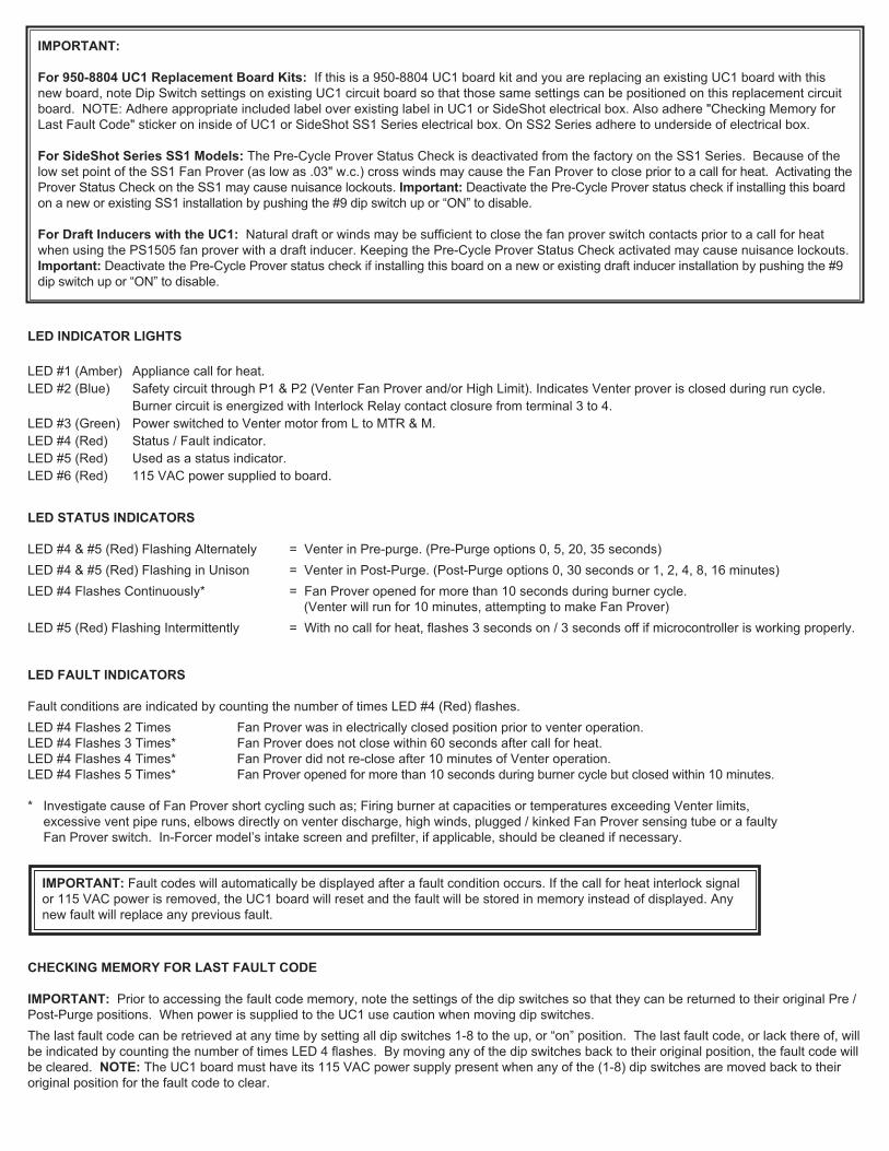
UC1 UNIVERSAL CONTROL WIRING SCHEMATIC
The Ground lead, Venter motor and Fan Prover leads are factory connected to the UC1 circuit board. Venter Ground, motor and FanProver wiring connections are made at the free end of the 2 foot whip in HS-Series junction box.
WIRING CONNECTIONS FROM UC1 UNIVERSAL CONTROL MADE INHS-SERIES JUNCTION BOX
1. Connect ground from UC1 whip to grounding stud in Venter.
2. Connect Black and White leads from UC1 whip to Venter motor leads.
3. Connect Blue and Yellow leads from UC1 whip to Fan Prover switch terminals in Venter. Yellow lead should be on switch terminal closest to Venter junction box wall.
4. Insert provided hole plug in HS-Series junction box in opening opposite UC1 whip.
MULTIPLE APPLIANCE INTERLOCKSTo interlock with one additional 24/115 VAC heater add the MAC1E. It is a strippeddown auxiliary board version of the UC1 and is powered by and communicates withthe UC1 through a factory wired whip.
To interlock more than two 24/115 VAC heaters, add the MAC4E for a total of up to5 heaters. It is powered by and communicates with the UC1 through a factory wiredwhip. Consult factory for installations with more than 5 heaters.
To interlock a millivolt water heater and a 24/115 VAC furnace or boiler, add theWHKE and MAC1E.
MILLIVOLT INSTALLATIONS Each millivolt appliance interlocked with the UC1 must have its own WHKE kitinstalled. The WHKE Gas Pressure Switch actuates the Venter through the A - B Drycontacts. The Linear Limit switch disables the heater in the event of a venting mal-function. IMPORTANT: Each millivolt appliance interlocked with the UC1 must haveits own Linear Limit spill switch.
MULTIPLE MILLIVOLT HEATER INSTALLATIONSMultiple millivolt heaters can be installed by using the A-B dry contact terminals ofthe UC1, MAC1E or MAC4E. Wire each WHKE gas pressure switch in parallelacross A-B terminals of UC1, MAC1E or MAC4E. Wire Linear Limit safety switchinto each individual millivolt heater. For further information consult factory or WHKEinstructions.

12
UC1 UNIVERSAL CONTROL CONNECTED WITH A 24 VAC ELECTRONIC IGNITION MODULE
XNR
UN
IVER
SAL C
ON
TRO
LLER
D/N 9183046-8
115 VAC
24 VAC
LEGEND:
HONEYWELL IGNITIONCONTROL
MV
MV
PV
CALL
AS APPLIANCE INTERLOCK VOLTAGE.RED JUMPER POSITION MUST BE THE SAME
XL
J1J2
DR
Y
115V
24V
IMPORTANT:
PVMV / PV (2)MV (1)
PV (3)BNR GND (4)
24V GND (5)24V (6)
(7)
(8)
SPARK (9)OR
PI
YE
GR
YE
WH
OR
YE
WH
OR
GR
GAS VALVE
JUMPER
50/60 Hz
SUPPLY115 VAC
SPADE TERMINAL IN ELECTRICAL BOX.
GROUND
CRIMP GROUND WIRE TO GROUNDING IMPORTANT:
1. Remove the wire on MV at gas valve and connect it on #1 on UC1 terminal block. 2. Connect #2 on UC1 terminal block to MV/PV. 3. Connect #4 on UC1 terminal block to MV on gas valve.4. Make sure RED voltage jumper on UC1 is on 24V.5. Connect 115 VAC supply voltage to L & N terminals on UC1. Crimp Ground wire to grounding spade terminal in UC1.
Important: Installer must supply overload and disconnect protection.6. If not previously completed, connect ground from UC1 whip to grounding stud in Venter. Connect Black and White leads
from UC1 whip to Venter motor leads. Connect Blue and Yellow leads from UC1 whip to Fan Prover switch terminals in Venter. Yellow lead should be on switch terminal closest to Venter junction box wall.
UC1 UNIVERSAL CONTROL CONNECTED WITH A 24 OR 115 VAC STANDING PILOT
115V
24V
DR
Y
OF FURNACE/BOILERINTERNAL CONTROLS
24V OR 115V GAS VALVE
HOT
COMB2
COMTR
AquastatT-stat
TH
HOTB1
XL
UN
IVERSAL C
ON
TRO
LLER
XNJ1
J2
D/N 9183046-1
24 OR 115 VAC
LEGEND:
CALLJUMPER
115 VAC
50/60 Hz
SUPPLY115 VAC
SPADE TERMINAL IN ELECTRICAL BOX.
GROUND
CRIMP GROUND WIRE TO GROUNDING IMPORTANT:
RED JUMPER POSITION MUST BE THE SAMEAS APPLIANCE INTERLOCK VOLTAGE.
IMPORTANT:
1. Remove the wire on TH or HOT of gas valve and connect it on #1 on UC1 terminal block. 2. Connect #2 on UC1 terminal block to TR or Common. 3. Connect #4 on UC1 terminal block to TH or HOT on gas valve.4. Make sure RED voltage jumper on UC1 is on 24V or 115V depending on control voltage.5. Connect 115 VAC supply voltage to L & N terminals on UC1. Crimp Ground wire to grounding spade terminal in UC1.
Important: Installer must supply overload and disconnect protection.6. If not previously completed, connect ground from UC1 whip to grounding stud in Venter. Connect Black and White leads
from UC1 whip to Venter motor leads. Connect Blue and Yellow leads from UC1 whip to Fan Prover switch terminals in Venter. Yellow lead should be on switch terminal closest to Venter junction box wall.
NOTE: If burner safety control goes out on lockout, the Venter will continue to run as long as a call for heat is present.

13
UC1 UNIVERSAL CONTROL CONNECTED WITH A SINGLE ZONE 24 VAC THERMOSTAT
XNR
UN
IVERSAL C
ON
TRO
LLER
THERMOSTAT
GG
INTERNAL CONTROLOF FURNACE
W
CY
R
RY
AS APPLIANCE INTERLOCK VOLTAGE.RED JUMPER POSITION MUST BE THE SAME
XLJ1
J2
W
DR
Y
115V
24V
IMPORTANT:
D/N 9183046-5
115 VAC
24 VAC
LEGEND:
CALLJUMPER
50/60 Hz
SUPPLY115 VAC
SPADE TERMINAL IN ELECTRICAL BOX.
GROUND
CRIMP GROUND WIRE TO GROUNDING IMPORTANT:
1. Connect W from t-stat to #1 on terminal block of UC1. 2. Connect #2 on UC1 terminal block to C on internal control terminal strip of furnace/boiler. 3. Connect #4 on UC1 terminal block to W on internal control terminal strip of furnace/boiler. 4. Make sure RED voltage jumper on UC1 is on 24V.5. Connect 115 VAC supply voltage to L & N terminals on UC1. Crimp Ground wire to grounding spade terminal in UC1.
Important: Installer must supply overload and disconnect protection.6. If not previously completed, connect ground from UC1 whip to grounding stud in Venter. Connect Black and White leads
from UC1 whip to Venter motor leads. Connect Blue and Yellow leads from UC1 whip to Fan Prover switch terminals in Venter. Yellow lead should be on switch terminal closest to Venter junction box wall.
NOTE: If burner safety control goes out on lockout, the Venter will continue to run as long as a call for heat is present.
UC1 UNIVERSAL CONTROL AND WHKE INTERLOCK KIT CONNECTED WITH A MILLIVOLT APPLIANCE
XNR
UN
IVE
RS
AL C
ON
TRO
LLER D/N 9183046-9
CALL
AS APPLIANCE INTERLOCK VOLTAGE.RED JUMPER POSITION MUST BE THE SAME
XLJ1
J2
DR
Y
115V
24V
IMPORTANT:
JUMPER
GENERATED
5 VDC
LEGEND:
115 VAC
WHKE GAS
SAFETY CIRCUIT ACROSS P1 & P2 OF UC1 IS NOT UTILIZED
WITH HEATING EQUIPMENT AS SHOWN.IN THIS APPLICATION. SPILL SWITCH MUST BE INTERLOCKED
MILLIVOLT
PRESSURESWITCH
JUNCTION ADAPTERTHERMOCOUPLE
950-0470 (JA1)
LINEAR LIMITSPILL SWITCH
GASVALVE
30 MILLIVOLT WATER HEATERS REQUIRE USE OF THE
(ECO) OF WATER HEATER. LINEAR LIMIT SPILL SWITCH,
ON 750 MILLIVOLT (POWER PILE) WATER HEATERS WIRELINEAR LIMIT SPILL SWITCH IN SERIES WITH HIGH LIMIT
950-0470 THERMOCOUPLE JUNCTION ADAPTER.
950-0470 JUNCTION ADAPTER AND GAS PRESSURESWITCH ARE INCLUDED WITH WHKE KIT.
DO NOTSUPPLY
POWER.
POWER!
BOARD-
50/60 Hz
SUPPLY115 VAC
ELECTRICAL BOX.
GROUND
CRIMP GROUND WIRE TO GROUNDING SPADE TERMINAL IN IMPORTANT:
Each millivolt appliance interlocked with the UC1 must have its own WHKE kit installed. The WHKE Gas Pressure Switch actuates theVenter through the A - B Dry contacts. The Linear Limit switch disables the heater in the event of a venting malfunction. IMPORTANT:Each millivolt appliance interlocked with the UC1 must have its own Linear Limit spill switch.
1. Wire WHKE Gas Pressure Switch across A and B terminals on UC1. Do not supply voltage to A and B terminals.2. Wire WHKE Linear Limit in series with thermocouple junction adapter or high limit ECO of water heater. 3. Make sure RED voltage jumper on UC1 is in the DRY position.4. Connect 115 VAC supply voltage to L & N terminals on UC1. Crimp Ground wire to grounding spade terminal in UC1.
Important: Installer must supply overload and disconnect protection.5. If not previously completed, connect ground from UC1 whip to grounding stud in Venter. Connect Black and White leads
from UC1 whip to Venter motor leads. Connect Blue and Yellow leads from UC1 whip to Fan Prover switch terminals in Venter. Yellow lead should be on switch terminal closest to Venter junction box wall.

14
UC1 UNIVERSAL CONTROL CONNECTED TO A HONEYWELL R7184 SERIES OR EQUIVALENTPRIMARY CONTROL WITH A LINE VOLTAGE THERMOSTAT OR AQUASTAT
Burner
AlarmCad CellA
Interrupted
Intermittant
Motor
A
IGNITION TRANS
BURNER MOTOR
R
Oil Valve
Limit
R7184
L1T
T L2
OIL VALVE
115 VAC60 Hz
SUPPLY
Limit
24VD
RY
115V
XL
UN
IVE
RS
AL C
ON
TRO
LLER
XN
J1J2
RED JUMPER POSITION MUST BE THE SAMEAS APPLIANCE INTERLOCK VOLTAGE.
IMPORTANT:
D/N 9183046-6
115 VAC
LEGEND:
CALLJUMPER
Ignitor
Line Voltage Thermostator Aquastat Control
Low VoltageJumper
50/60 Hz
SUPPLY115 VAC
SPADE TERMINAL IN ELECTRICAL BOX.
GROUND
CRIMP GROUND WIRE TO GROUNDING IMPORTANT:
1. Disconnect burner motor wire off the R7184.2. Connect burner motor terminal of R7184 to #1 on UC1 terminal block.3. Connect #2 on UC1 terminal block to L2 or N.4. Connect #4 on UC1 terminal block to burner motor wire removed from R7184. 5. Make sure RED voltage jumper on UC1 is on 115V.6. Connect 115 VAC supply voltage to L & N terminals on UC1. Crimp Ground wire to grounding spade terminal in UC1.
Important: Installer must supply overload and disconnect protection.7. If not previously completed, connect ground from UC1 whip to grounding stud in Venter. Connect Black and White leads
from UC1 whip to Venter motor leads. Connect Blue and Yellow leads from UC1 whip to Fan Prover switch terminals in Venter. Yellow lead should be on switch terminal closest to Venter junction box wall.
UC1 UNIVERSAL CONTROL CONNECTED TO A GAS OR OIL BURNER WITH AN AQUASTAT
XNR
UN
IVER
SAL C
ON
TRO
LLER
LINE VOLTAGE OIL BURNERPRIMARY CONTROL, BURNER
L1
N
XLJ1
J2
115V
DR
Y24V
AQUASTAT
B2B1
C1C2
L1L2
D/N 9183046-7
115 VAC
LEGEND:
CALLJUMPER
RELAY OR GAS VALVE50/60 Hz
SUPPLY115 VAC
RED JUMPER POSITION MUST BE THE SAMEIMPORTANT:
AS APPLIANCE INTERLOCK VOLTAGE.
SPADE TERMINAL IN ELECTRICAL BOX.
GROUND
CRIMP GROUND WIRE TO GROUNDING IMPORTANT:
CAUTION:WHEN INTERLOCKING WITH AQUASTAT DO NOT DISCONNECT BURNER MOTOR FROM PRIMARY CONTROL / CAD CELL RELAY.
1. Disconnect B1 from L1 of oil burner primary control, burner relay or hot of gas valve and reconnect to #1 on UC1 terminal block.2. Connect #2 on UC1 terminal block to B2 or N.3. Connect #4 on UC1 terminal block to the L1 on line voltage oil burner primary control, burner relay or gas valve.4. Make sure RED voltage jumper on UC1 is on 115V.5. Connect 115 VAC supply voltage to L & N terminals on UC1. Crimp Ground wire to grounding spade terminal in UC1.
Important: Installer must supply overload and disconnect protection.6. If not previously completed, connect ground from UC1 whip to grounding stud in Venter. Connect Black and White leads
from UC1 whip to Venter motor leads. Connect Blue and Yellow leads from UC1 whip to Fan Prover switch terminals in Venter. Yellow lead should be on switch terminal closest to Venter junction box wall.
NOTE: If burner safety control goes out on lockout, the Venter will continue to run as long as a call for heat is present.

15
UC1 UNIVERSAL CONTROL CONNECTED TO A HONEYWELLR8184 SERIES OR EQUIVALENT PRIMARY CONTROL
50/60 Hz
R
WHITE
ORANGE
BLACK
HONEYWELLR8184 SERIES
OR EQUIVALENT
IGNITION TRANS
BURNER MOTOR
WHITE
SUPPLY115 VAC
BLACK
UN
IVE
RS
AL C
ON
TRO
LLER
XN
RED JUMPER POSITION MUST BE THE SAMEIMPORTANT:
AS APPLIANCE INTERLOCK VOLTAGE.
J1XL
J2
115V
DR
Y24V
115 VAC
LEGEND:
CALLJUMPER
SPADE TERMINAL IN ELECTRICAL BOX.
GROUND
CRIMP GROUND WIRE TO GROUNDING IMPORTANT:
D/N 9183046-2 10/16/03
L1 OR B1CONNECT TO
CONNECT TOL2 OR B2
WHITE
1. Separate the Black burner motor wire from the Orange wire of R8184 Primary Control. NOTE: Do not separate the ignition transformer wire from the Orange.
2. Connect Orange wire of R8184 to #1 on UC1 terminal block. 3. Connect #2 on UC1 terminal block to White on R8184 and L2 or B2.4. Connect Black of burner motor to #4 on UC1 terminal block.5. Make sure RED voltage jumper on UC1 is on 115V.6. Connect 115 VAC supply voltage to L & N terminals on UC1. Crimp Ground wire to grounding spade terminal in UC1.
Important: Installer must supply overload and disconnect protection.7. If not previously completed, connect ground from UC1 whip to grounding stud in Venter. Connect Black and White leads
from UC1 whip to Venter motor leads. Connect Blue and Yellow leads from UC1 whip to Fan Prover switch terminals in Venter. Yellow lead should be on switch terminal closest to Venter junction box wall.
UC1 UNIVERSAL CONTROL CONNECTED WITH A CARLIN 40200, 42230, 48245, 50200, 60200 SERIES OR EQUIVALENT AND A LINE VOLTAGE THERMOSTAT OR AQUASTAT
Alarm
A Violet0.3 A, AC
OIL VALVE
R
A Blue
OrangeF
F White
T Black
Red/WhiteT
115 VAC
BURNER MOTOR
IGNITION TRANS500 VA
10 FLA / 60 LRA
Line Voltage Thermostat
60 Hz
SUPPLY
J2 UN
IVE
RS
AL C
ON
TRO
LLER
XNXL
J1
RED JUMPER POSITION MUST BE THE SAMEAS APPLIANCE INTERLOCK VOLTAGE.
IMPORTANT:
115V
DR
Y24V
D/N 9183046-3
115 VAC
LEGEND:
CALLJUMPER
Limitor Aquastat Control
Low VoltageJumper
50/60 Hz
SUPPLY115 VAC
SPADE TERMINAL IN ELECTRICAL BOX.
GROUND
CRIMP GROUND WIRE TO GROUNDING IMPORTANT:
1. Disconnect burner motor wire off the Orange on Carlin.2. Connect burner motor terminal Orange of Carlin to #1 on UC1 terminal block.3. Connect #2 on UC1 terminal block to L2 or N4. Connect #4 on UC1 terminal block to burner motor wire removed from Orange of Carlin.5. Make sure RED voltage jumper on UC1 is on 115V.6. Connect 115 VAC supply voltage to L & N terminals on UC1. Crimp Ground wire to grounding spade terminal in UC1.
Important: Installer must supply overload and disconnect protection.7. If not previously completed, connect ground from UC1 whip to grounding stud in Venter. Connect Black and White leads
from UC1 whip to Venter motor leads. Connect Blue and Yellow leads from UC1 whip to Fan Prover switch terminals in Venter. Yellow lead should be on switch terminal closest to Venter junction box wall.

16
UC1 UNIVERSAL CONTROL OPERATIONAL CHECK
1. Confirm power is supplied to the Control. LED #6 (RED) should be on.
2. Activate the UC1 by initiating an appliance call for heat. LED #1 (AMBER) should be on.
3. The motor relay will close and activate the Venter motor. LED #3 (GREEN) should be on and Venter motor should be running.
4. If the safety circuit across P1 & P2 (Venter Prover) is closed, indicating an approved condition, the appliance interlock relay will close making terminal #3 closed to terminal #4 & LED #2 (BLUE).Appliance burner should fire.
5. Remove power to the UC1 and any interlocked appliances. The LED #6 (RED) or any LED’s should not be on. Test the safety circuit by removing the Blue or Yellow Lead from Fan Proving Switch. Do not let the opened Lead touch a ground or damage may occur to the control whenpower is Reestablished. Reestablish power to the UC1 and interlocked appliances and initiate a call for heat. After 60 seconds a Prover Start Up fault should arise with LED #4 flashing 3 times.
6. Remove appliance call for heat and power to the UC1 and any interlocked appliances. The LED #6 (RED) or any LED’s should not be on. Reconnect Blue or Yellow Fan Prover lead to Fan Proving Switch terminal removed from in step 5.
7. Reestablish power to UC1 and interlocked appliances and initiate a call for heat to confirm proper operation of UC1 and appliance. RESETTING FAULT CODE CREATED BY STEP 5 OF OPERATIONAL CHECKIMPORTANT: Prior to accessing the fault code memory, note the settings of the dip switches so that they can be returned to theiroriginal Pre / Post-Purge positions. When power is supplied to the UC1 use caution when moving dip switches.The last fault code can be retrieved at any time by setting all dip switches 1-8 to the up, or “on” position. The last fault code, or lackthere of, will be indicated by counting the number of times LED 4 flashes. By moving any of the dip switches back to their originalposition, the fault code will be cleared. NOTE: The UC1 board must have its 115 VAC power supply present when any of the (1-8) dipswitches are moved back to their original position for the fault code to clear.
UC1 UNIVERSAL CONTROL CONNECTED TO AN OIL-FIRED FURNACE WITH AHONEYWELL T87 OR EQUIVALENT NON-POWERED THERMOSTAT
XNR
UN
IVER
SAL C
ON
TRO
LLER
REMOVE JUMPER TO AVOID
AS APPLIANCE INTERLOCK VOLTAGE.RED JUMPER POSITION MUST BE THE SAME
XL
J1J2
DR
Y
115V
24V
IMPORTANT:
BACKFEEDS OR SHORT
50/60 Hz
SUPPLY115 VAC
NON-POWERED THERMOSTAT
FF
TT
D/N 9183047-1
PRIMARY CONTROL
SPADE TERMINAL IN ELECTRICAL BOX.
GROUND
CRIMP GROUND WIRE TO GROUNDING IMPORTANT:
OR EQUIVALENT5 VDC BOARD-GENERATED
LEGEND:
115 VAC
DO NOT SUPPLY POWER!POWER.
LOW VAC
HONEYWELL T87 OR EQUIVALENT
W
OWHITE
ORANGEB
BLACK
HONEYWELLR8184 SERIES
IMPORTANT:
FACTORY-WIRED
CIRCUITS.
1. IMPORTANT: Remove J1 & J2 Call Jumper on UC1 to avoid backfeeds or short circuits.2. Connect T87 or Equivalent non-powered thermostat to A and B terminals on UC1. 3. Remove T T Jumper from R8184 or equivalent Primary Control.4. Connect #3 on UC1 terminal block to T terminal of Primary Control. 5. Connect #4 on UC1 terminal block to remaining T terminal of Primary Control.6. Make sure RED voltage jumper on UC1 is on DRY.7. Connect 115 VAC supply voltage to L & N terminals on UC1. Crimp Ground wire to grounding spade terminal in UC1.
Important: Installer must supply overload and disconnect protection.8. If not previously completed, connect ground from UC1 whip to Venter ground. Connect Black and White leads from UC1 whip
to Venter motor leads. Connect Blue and Yellow leads from UC1 whip to Fan Prover switch. Prover Leads are not polarity sensitive.
NOTE: If burner safety control goes out on lockout, the Venter will continue to run as long as a call for heat is present.
LED 1 AMBERLED 2 BLUELED 3 GREENLED 4 REDLED 5 RED
LED 6 REDPOWER LED
ON1 9

17
DRAFT CHECK, SAFETY INTERLOCK & COMBUSTION AIR TEST
The Power Venter Fan Proving Switch is designed to disable the appliance gas valve or burner motor upon Power Venter failure only!It is not designed and cannot replace, regular vent system inspection, appliance servicing and combustion testing.
1. Close all doors and windows of the building. If the appliance is installed in a utility room or closet, close the entrance door to this room. Close fireplace dampers.
2. Turn on clothes dryer and all exhaust fans such as range hoods, bathroom exhausts and whole house fans to maximum speeds. Do not operate a fan used strictly for Summer exhausting.
3. Following the appliance manufacturer’s instructions, place the appliance in operation, set thermostat for continuous operation.
4. Verify that Power Venter operates first, prior to burner ignition. Watch to make sure burner lights off properly.
GASAfter allowing appliance(s) to operate for 15 minutes, follow the appliance manufacturers instructions to verify that the recommendeddraft is present. In general, most gas appliances will operate safely with flue outlet draft levels from -0.02 to -0.05" W.C.. If the draftis excessive, make necessary adjustments to the barometric control and/or follow the, “Power Venter Air Flow Damper Adjustment”procedure outlined below. As a cross check, a candle or match can be held adjacent to the draft hood or barometric control to verifyflame/smoke is being drawn into, and not rolling out of edge of the relief opening, (See Diagram I). If exhaust gases are escapingfrom the relief opening of the draft hood or barometric control, the equipment should not be operated until proper adjustments orrepairs are made to provide adequate draft levels.
OILAfter allowing equipment to operate for 15 minutes, make necessary adjustments to the primary air intake and barometric draft controlto comply with the manufacturer recommended over-fire draft and CO2 requirements of the burner. In most cases, the over-fire draftshould be in a range of -.02” to -.04” W.C. If adjustments to the primary air intake and barometric draft control do not provide therequired over-fire draft, the Power Venter draft adjustment must be repositioned accordingly. Measure over-fire draft after reposition-ing Power Venter draft adjustment, (See Diagram J).5. Next, turn on all other fuel-burning appliances within the same room so they will operate at their full input. Repeat Step 3 above,
checking the draft on each appliance.
POWER VENTER AIR FLOW DAMPER ADJUSTMENT
The Air Flow Damper Adjustment on the Power Venter is factory set for maximum air flow. Operating a properly sized Power Venter atits maximum setting will assure that combustion gases are safely removed to the outside. If the Power Venter has excess ventingcapacity than what is required for this application, operating the Power Venter with the air-flow adjustment at the maximum settingmay draw more dilution air than necessary.The Air Flow Damper Adjustment may be set by use of a combustion analyzer, inclined manometer or draft gauge. Alternatively, thedamper adjustment can be set using a smoke candle or taper, as follows:
1. With all exhaust fans operating, air inlets closed and all appliances firing (as instructed above), hold a lighted match or taper around the edge of the relief opening of the draft hood(s) or barometric draft control, (See Diagram I).
2. Set Air Flow Adjustment by loosening locknut and turning damper rod handle. CAUTION: HANDLE MAY BE HOT, use pliers to move handle. Position of rod handle indicates the position of Air Flow Adjustment inside housing, (See Diagram J).
3. Using pliers, move handle towards minimum draft setting until spillage is detected at draft hood relief opening, then re-open Air Flow Adjustment justenough to eliminate spillage.
4. Lock Air Flow Adjustment at desired setting by tightening locknut.
5. Return doors, windows, exhaust fans, fireplace dampers and appliances to their previous conditions of use.
COMBUSTION AIRAdequate combustion air is vital for proper combustion and for safe venting. Likewise, for proper Power Venter performance, ade-quate combustion air must be available to the appliance. Many installers assume adequate combustion air is present, especially inolder homes. In some cases this is a false assumption, because many older homes have been made "tight" due to weatherization.Size the combustion air opening(s) into the appliance room as outlined local or national codes. Tjernlund’s IN-FORCERTM CombustionAir Intake Systems provide a convenient interlocked way to provide combustion air to the equipment room. When installing a PowerVenter it is not necessary to supply any more combustion air than normally required when conventional venting. Common symptomsof inadequate combustion air include: Fan Proving Switch short cycling, odor present at end of burner cycle, outside air enters thestructure through the Power Venter during appliance off cycle.
DIAGRAM I
PROPER DRAFTESTABLISHED
PROPER DRAFTESTABLISHED
DIAGRAM J

18
MAINTENANCE1. The HSJ,1,2 motors are permanently lubricated and do not need to be oiled.
2. The end-user must semiannually inspect the Vent Hood and vent pipe for blockage, corrosion and leaks.
3. A vent system inspection must be performed annually by a qualified service agency. The inspection should include the operation circuit check, safety interlock test, combustion air test and a visual inspection of the complete vent system for corrosion, blockage or leaks. Any corrosion, blockage or leaks detected must be repaired or replaced immediately.
TROUBLESHOOTING
The following guide is intended to be used if a problem occurs during the use of the Venter and UC1. It may be necessary to measure voltage duringtroubleshooting. Extreme caution must be exercised to prevent injury. If you are unable to determine the defective part with the use of this guide,call your Tjernlund distributor or Tjernlund Products at 1-800-255-4208 for further assistance.
IMPORTANT: If the call for heat interlock signal or 115 VAC power is removed, the UC1 board will reset and any fault, if present, will be stored inmemory instead of displayed. See page 5, “Checking Memory for Last Fault Code”.
LED STATUS & FAULT INDICATORSLED INDICATOR LIGHTS LED #1 (Amber) Appliance call for heat.LED #2 (Blue) Safety circuit through P1 & P2 (Venter Fan Prover). Indicates Venter prover is closed during run cycle.
Burner circuit is energized with Interlock Relay contact closure from terminal 3 to 4. LED #3 (Green) Power switched to Venter motor from L to MTR & M.LED #4 (Red) Status / Fault indicator.LED #5 (Red) Used as a status indicator.LED #6 (Red) 115 VAC power supplied to board.
LED STATUS INDICATORSLED #4 & #5 (Red) Flashing Alternately = Venter in Pre-purge. (Pre-Purge options 0, 5, 20, 35 seconds)LED #4 & #5 (Red) Flashing in Unison = Venter in Post-Purge. (Post-Purge options 0, 30 seconds or 1, 2, 4, 8, 16 minutes)LED #4 (Red) Flashing Continuously* = Fan Prover opened for more than 10 seconds during burner cycle.
(Venter will run for 10 minutes, attempting to make Fan Prover)LED #5 (Red) Flashing Intermittently = With no call for heat, flashes 3 seconds on / 3 seconds off if microcontroller is working properly.
LED FAULT INDICATORS Fault conditions are indicated by counting the number of times LED #4 (Red) flashes.LED #4 Flashes 2 Times Fan Prover was in electrically closed position prior to venter operation.LED #4 Flashes 3 Times* Fan Prover does not close within 60 seconds after call for heat.LED #4 Flashes 4 Times* Fan Prover did not re-close after 10 minutes of Venter operation.LED #4 Flashes 5 Times* Fan Prover opened for more than 10 seconds during burner cycle but closed within 10 minutes.
* Investigate causes of Fan Prover not making, i.e; Firing burner at capacities or temperatures exceeding Venter limits, excessive vent pipe runs, elbows directly on venter discharge, high winds, plugged / kinked Fan Prover sensing tube or a faulty Fan Prover.
SYMPTOM 1: VENTER OPERATES CONTINUOUSLYVerify that Venter is not in post-purge mode which could last up to 16 minutes. A factory post-purge has been set for 2 minutes. LED #4 & #5 (Red)will flash in unison during post-purge. A Venter pre-purge could also be set for up to 35 seconds. LED #4 & #5 (Red) will flash alternately during pre-purge. See “Pre / Post-Purge Settings” on page 5.Verify that LED #1 (Amber) is not lit. Yes, LED #1 (Amber) is lit: Check interlock wiring. Confirm burner control(s) are functioning properly. UC1 control is receiving constant call for heat signal.LED #1 (Amber) is not lit: Replace UC1 circuit board part number 950-8804.
SYMPTOM 2: VENTER MOTOR DOES NOT OPERATEVerify that UC1 control has power, LED #6 (Red) should be lit. Verify that LED# 4 (Red) is not flashing. See “LED Status & Fault Indicators” above ifflashing. Verify RED voltage selection jumper corresponds with interlock voltage (i.e 24V, 115V or “Dry”).No: Check circuit breaker, disconnect switches and wiring. Confirm that Venter motor leads are connected to N & MTR terminals. Yes, LED #6 (Red) is lit: Verify that the interlocked burner is calling for heat, LED #1 (Amber) should be lit.No, LED #1 (Amber) is not lit: Verify interlock wiring and that thermostat/aquastat is adjusted to call for heat. Verify that the REDvoltage selection jumper is installed so that it matches the voltage of the interlocked burner.Yes, LED #1 (Amber) is lit: Verify Prover safety circuit fault does not exist. See, “LED Status & Fault Indicators” above. If faults exist check Prover P1 & P2 safety circuit. If no faults exist, check for 115 VAC across terminals N and MTR.Voltage present: Confirm Black and White leads from UC1 whip are securely fastened to Venter motor leads. If so, replace Venter motor.No voltage present: Replace UC1 circuit board part number 950-8804.
IMPORTANT: Fault codes will automatically be displayed after a fault condition occurs. If the call for heat interlock signal or 115 VACpower is removed, the UC1 board will reset and the fault will be stored in memory instead of displayed. Any new fault will replaceany previous fault. See page 5, “Checking Memory for Last Fault Code”.
19
SYMPTOM 3: VENTER OPERATES, BUT BURNER DOES NOTFor any newly established call for heat the UC1 will run for 60 seconds to try to close the fan prover circuit (P1 to P2). If circuit can not be made within60 seconds, LED #4 (Red) will flash 3 times, indicating a prover check circuit fault on UC1 start up. NOTE: The UC1 safety circuit and LED #4 (Red)will be reset if the call for heat interlock signal or 115 VAC power is removed. If the fan prover makes on start up, but breaks for more than 10 sec-onds during the burner cycle, LED #4 will flash continuously indicating a prover circuit fault. The Venter will continue to run for 10 minutes to try tomake the prover circuit as long as a call for heat exists. If Prover does not make within 10 minutes, the UC1 will shut down and LED #4 (Red) willflash 4 times indicating a prover circuit fault. Remove the call for heat and then reestablish to reset the UC1 prover safety circuit (P1 to P2) & LED #4 (Red). Verify that LED #2 (Blue) is lit.Yes, LED #2 (Blue) is lit: Verify that "call jumper" is connected from J1 to J2 on UC1 circuit board if using typical wiring where supply voltage from ter-minal 1 is routed to terminal 3 through “call jumper” then to 4 when appliance interlock relay makes. With call for heat established, verify that wiring iscorrect by measuring voltage between terminals 1 & 2 and 2 & 4 of UC1 terminal strip. Voltage should be the same in both cases, if not rewire perappropriate diagram or confirm burner control(s) are functioning properly. NOTE: If a different voltage source is provided to terminal 3 which isswitched to terminal 4 or when using the A-B dry contacts, voltage measurements may not apply. For millivolt installations make sure system Limitsare reset and relight pilot. No, LED #2 (Blue) is not lit: Remove power from UC1 and push dip switch #9 up or “on” to deactivate Pre-Cycle Fan Prover status check. RemoveP1 and P2 prover leads off of Fan Prover switch and jumper together. Reestablish power and call for heat. After Venter pre-purge, if set (up to 35 seconds),LED #2 (Blue) should light.No, LED #2 (Blue) does not light: Replace UC1 circuit board, part number 950-8804.Yes, LED #2 (Blue) lights up: The fan proving switch may not be closing, wiring connections are incorrect/broken or burner control(s) are not function-ing properly. With Venter running, verify that Venter performance is sufficient to close Fan Prover contacts by checking for continuity across switch.IMPORTANT: After continuity check push dip switch #9 back down to “activate” Pre-Cycle Fan Prover status check. Replace Fan Prover leads fromP1 and P2 back on Fan Proving switch. No, continuity is not present: Confirm that burner is not firing at capacities or temperatures exceeding Venter limits. Check for excessive vent piperuns, elbows directly on venter discharge, high winds, plugged / kinked Fan Prover sensing tube or a faulty Fan Prover switch. If everything checksout okay, replace fan prover.Yes, continuity present: Recheck wiring and burner control(s).
HOW TO OBTAIN SERVICE ASSISTANCE
If you have any questions about your Venter or if it requires adjustment or repair, we suggest you contact your installer, contractor or service agency. If you require technical information contact Tjernlund Products, Inc. at 1-800-255-4208 with the following information.
Model of the Venter the UC1 is interlocked with as shown on the label attached to Venter.Name and address of installer and any service agency who performed work on Venter.Date of original installation and dates any service work was performed.Details of the problem as you can best describe them.
LIMITED PARTS WARRANTY AND CLAIM PROCEDURE
Tjernlund Products, Inc. warrants the components of the Venter and UC1 for 1 year from date of installation. This warranty covers defects in materialand workmanship. This warranty does not cover normal maintenance, transportation or installation charges for replacement parts or any other servicecalls or repairs. This warranty DOES NOT cover the complete Venter if it is operative, except for the defective part.
1.) Follow troubleshooting guide to determine defective component. If unable to determine faulty component, contact your Tjernlund distributor or Tjernlund Products Technical Customer Service Department at 1-800-255-4208 for troubleshooting assistance.
2.) After the faulty component is determined, return it to your Tjernlund distributor for replacement. Please include Venter date code component was taken from. The date code is located on the Electrical Box coverplate. If the date code is older than 1 year, you will need to provide a copy of theoriginal installation receipt to your distributor. Credit or replacement will only be issued to a Tjernlund distributor after the defective part has been returned prepaid to Tjernlund and verified defective.
WHAT IS NOT COVERED
Product installed contrary to our installation instructions, altered, neglected, misused or wired incorrectly.Product that has been damaged by a malfunctioning or maladjusted burner.Any freight charges related to the return of the defective part.Any labor charges related to evaluating and replacing the defective part
MODEL HSJ DESCRIPTION PART NUMBER MOTOR KIT 950-1020WHEEL KIT 950-1010FAN PROVER KIT 950-1030UC1 CIRCUIT BOARD 950-8804
MODEL HS2 DESCRIPTION PART NUMBER MOTOR KIT W/WHEEL 950-1021WHEEL KIT 3/8” BORE 950-1012FAN PROVER KIT 950-1031UC1 CIRCUIT BOARD 950-8804
MODEL HS1 DESCRIPTION PART NUMBER MOTOR KIT 950-1020WHEEL KIT 950-1011FAN PROVER KIT 950-1030UC1 CIRCUIT BOARD 950-8804
TJERNLUND ONE YEAR LIMITED WARRANTY
Tjernlund Products, Inc. warrants to the original purchaser of this product that the product will be free from defects due to faulty material or workmanship for a period of (1) year fromthe date of original purchase or delivery to the original purchaser, whichever is earlier. Remedies under this warranty are limited to repairing or replacing, at our option, any productwhich shall, within the above stated warranty period, be returned to Tjernlund Products, Inc. at the address listed below, postage prepaid. THERE ARE NO WARRANTIES WHICHEXTEND BEYOND THE DESCRIPTION ON THE FACE HEREOF, AND TJERNLUND PRODUCTS, INC. EXPRESSLY DISCLAIMS LIABILITY FOR INCIDENTAL OR CONSE-QUENTIAL DAMAGES ARISING FROM THE USE OF THIS PRODUCT. THIS WARRANTY IS IN LIEU OF ALL OTHER EXPRESS WARRANTIES AND NO AGENT IS AUTHORIZEDTO ASSUME FOR US ANY LIABILITY ADDITIONAL TO THOSE SET FORTH IN THIS LIMITED WARRANTY. IMPLIED WARRANTIES ARE LIMITED TO THE STATED DURATIONOF THIS LIMITED WARRANTY. Some states do not allow limitation on how long an implied warranty lasts, so that limitation may not apply to you. In addition, some states do notallow the exclusion or limitation of incidental or consequential damages, so that above limitation or exclusion may not apply to you. This warranty gives you specific legal rights andyou may also have other rights which may vary from State to State. Send all inquiries regarding warranty work to Tjernlund Products, Inc. 1601 9th Street, White Bear Lake, MN 55110-6794. Phone (651) 426-2993 • (800) 255-4208 • Fax (651) 426-9547 • Email: [email protected]


![COVID-19 survey reportmydocs.epri.com/.../covid19/COVID-19_survey_report.pdfZZZ HSUL FRP î ì î ì o ] W } Á Z Z / v ] µ U / v X o o ] P Z À X ZZZ HSUL FRP î ì î ì o ] W }](https://img.dokumen.tips/doc/110x75/5fbb35cbe9a5654fc4113ad5/covid-19-survey-zzz-hsul-frp-o-w-z-z-v-u-v-x-o-o-p.jpg)