Embed Size (px)
Citation preview

1/1/4747Conventional TunneConventional Tunnellling in Urban Areas ling in Urban Areas -- GeneralGeneral
The 3rd Training course TUNNELLING IN URBAN AREA
Prague, 4-5th May 2007
Conventional TunneConventional Tunnellling in Urban ling in Urban Areas Areas -- GeneralGeneral
Miloslav Miloslav FrankovskyFrankovsky, , TerraprojektTerraprojekt a.s., a.s., SlovakiaSlovakiaPeter Stefko, Skanska Peter Stefko, Skanska –– BS a.s., SlovakiaBS a.s., Slovakia
ITA - AITES WORLD TUNNEL CONGRESS 2007 PRAGUE
TRAINING MATERIAL PREPARED BY

2/2/4747Conventional TunneConventional Tunnellling in Urban Areas ling in Urban Areas -- GeneralGeneral
5Conclusions Conclusions and and referencesreferences
ConventionalConventional tunnellingtunnelling
SpecialSpecial measuresmeasures duringduring tunneltunnel drivingdriving
IntroductionIntroduction
Waterproofing and finalWaterproofing and final lininglining
Index
2
3
4
1
Conventional TunneConventional Tunnellling in Urban Areas ling in Urban Areas -- GeneralGeneral
3/3/4747Conventional TunneConventional Tunnellling in Urban Areas ling in Urban Areas -- GeneralGeneral
Introduction
22
33
44
55
11
Definition of conventional tunnelling:
Any method of underground construction exceptmethods using full profile TBM could beconsidered as conventional tunnelling
Representatives:
• New Austrian Tunelling Method (NATM)• Shotcrete Lining Method (SLM)• ADECO method• Prevault method
4/4/4747Conventional TunneConventional Tunnellling in Urban Areas ling in Urban Areas -- GeneralGeneral
ConventionalConventional tunnellingtunnelling
22
33
44
55
11
Conventional tunnelling:
• Ground around the tunnel is considered to be loadbearing element
• Type and quantity of support elements is adjustedin combination with development of groundreaction
• Stability is confirmed by frequent monitoring ofground reactions mainly by deformationmeasurement
• Depending on the conditions the requirement ofstiff or light deformable support is identified

5/5/4747Conventional TunneConventional Tunnellling in Urban Areas ling in Urban Areas -- GeneralGeneral
ConventionalConventional tunnellingtunnelling
22
33
44
55
11
Typical support elements:
• Shotcrete lining reinforced by steel mesh or steelfibres
• Rock anchors of various types (SN, frictional, selftapping etc.)
• Steel ribs or lattice girders• Special measures ahead of the face (pipe roofs,
forepoling, face bolts etc.)
Subdivision of cross section usually depends on ground conditions, size of excavation and surfacesettlements control

6/6/4747Conventional TunneConventional Tunnellling in Urban Areas ling in Urban Areas -- GeneralGeneral
ConventionalConventional tunnellingtunnelling
22
33
44
55
11Hard rock conditions:
• Drill and blast excavation, partially mechanizedexcavation
• Subdivision into top heading and bench• Invert in case of poor rock conditions• Support classes framework defines advance
lengths, type and quantity of support elements• Waterproofing system from membrane and
drainage pipes on side of tunnel walls (umbrellasystem)
• Final lining from unreinforced or reinforcedconcrete
7/7/4747Conventional TunneConventional Tunnellling in Urban Areas ling in Urban Areas -- GeneralGeneral
ConventionalConventional tunnellingtunnelling
22
33
44
55
11Soft ground conditions without special requirements:
• Without buildings on surface above tunnel• Mechanized excavation• Subdivision into top heading, bench and invert• Special measures (e.g. pipe roofs, temporary invert,
elephant foot)• Shorter length of advance• Waterproofing system from membrane and drainage
pipes on side of tunnel walls (umbrella system)• Final lining from reinforced concrete usually adjusted
for full load of overburden

8/8/4747Conventional TunneConventional Tunnellling in Urban Areas ling in Urban Areas -- GeneralGeneral
ConventionalConventional tunnellingtunnelling
22
33
44
55
11Soft ground conditions with special requirements:
• Settlements on surface are to be restricted – urbanareas with buildings or communications
• Subdivision of cross section with rapid ring closure• Excavation of small sections of face with immediate
support• Short length of advance• Fully tanked lining system with or without membrane
without permanent drainage • Final lining from watertight reinforced concrete
designed for the full water pressure
9/9/4747Conventional TunneConventional Tunnellling in Urban Areas ling in Urban Areas -- GeneralGeneral
ConventionalConventional tunnellingtunnelling
22
33
44
55
11
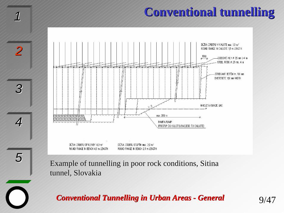
ExampleExample ofof tunnelling in poor rock conditions, Sitina tunnelling in poor rock conditions, Sitina tunnel, Slovakiatunnel, Slovakia

10/10/4747Conventional TunneConventional Tunnellling in Urban Areas ling in Urban Areas -- GeneralGeneral
ConventionalConventional tunnellingtunnelling
22
33
44
55
11
ExampleExample ofof tunnelling in soft groundtunnelling in soft ground conditionsconditions withwithdeformationdeformation restriction, Sitina tunnel, Slovakiarestriction, Sitina tunnel, Slovakia

11/11/4747Conventional TunneConventional Tunnellling in Urban Areas ling in Urban Areas -- GeneralGeneral
22
33
44
55
11 Interrelationships of tunnel design philosophiesInterrelationships of tunnel design philosophies

12/12/4747Conventional TunneConventional Tunnellling in Urban Areas ling in Urban Areas -- GeneralGeneral
SpecialSpecial measuresmeasures duringduring tunneltunnel drivingdriving
22
33
44
55
11The choosen Special Measures should make provision for:
Engineering and geological conditions - usualy soft groundconditionsHydrogeological conditionsThickness of overburdenLocation and distance to built up areaRestrictions – noise, vibration, working hours etc.Requirements – deformation limitations, settlement controlmeasures The size and geometry of excavating profile
13/13/4747Conventional TunneConventional Tunnellling in Urban Areas ling in Urban Areas -- GeneralGeneral
22
33
44
55
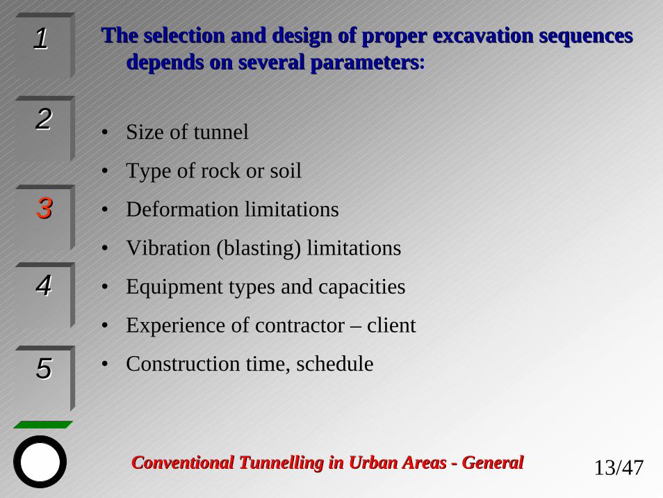
11 TheThe selection and design of properselection and design of proper excavationexcavation sequencessequencesdepends on severaldepends on several parametersparameters:
• Size of tunnel
• Type of rock or soil
• Deformation limitations
• Vibration (blasting) limitations
• Equipment types and capacities
• Experience of contractor – client
• Construction time, schedule

14/14/4747Conventional TunneConventional Tunnellling in Urban Areas ling in Urban Areas -- GeneralGeneral
22
33
44
55
11 SprayedSprayed concreteconcrete liningslinings
15/15/4747Conventional TunneConventional Tunnellling in Urban Areas ling in Urban Areas -- GeneralGeneral
SpecialSpecial measures measures –– division of excavation facedivision of excavation face
22
33
44
55
11
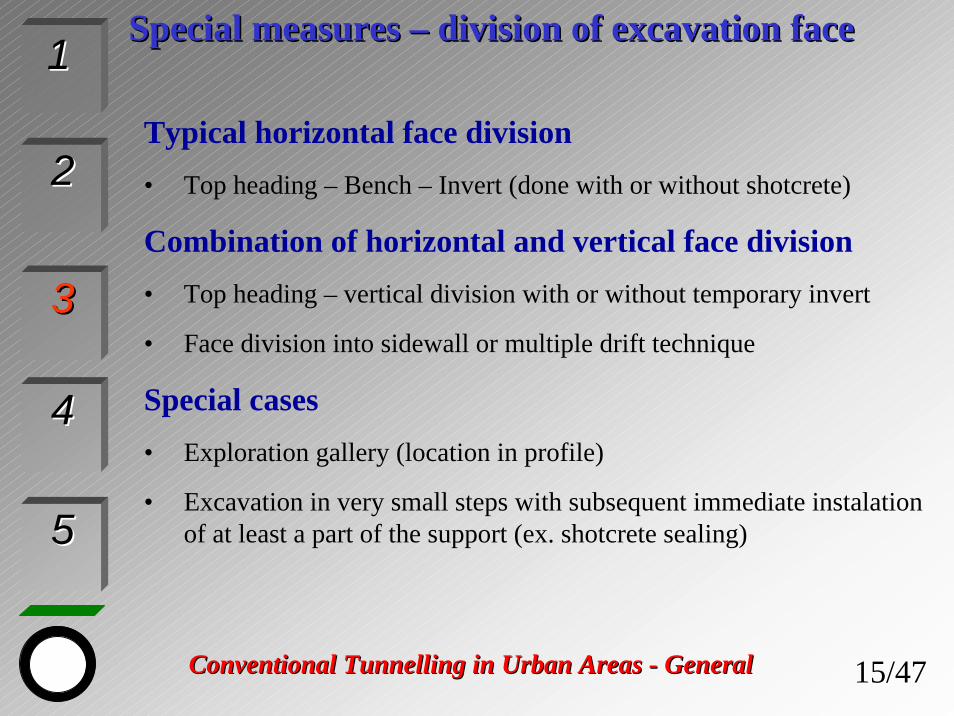
Typical horizontal face division• Top heading – Bench – Invert (done with or without shotcrete)
Combination of horizontal and vertical face division• Top heading – vertical division with or without temporary invert
• Face division into sidewall or multiple drift technique
Special cases• Exploration gallery (location in profile)
• Excavation in very small steps with subsequent immediate instalation of at least a part of the support (ex. shotcrete sealing)
16/16/4747Conventional TunneConventional Tunnellling in Urban Areas ling in Urban Areas -- GeneralGeneral
22
33
44
55
11
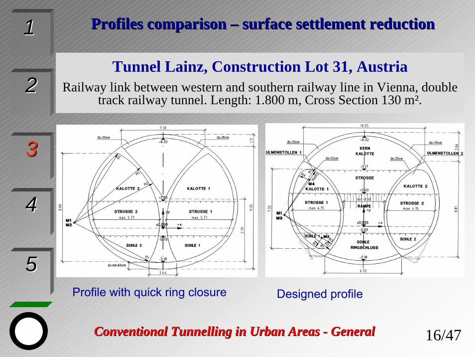
Profile with quick ring closure Designed profile
Tunnel Lainz, Construction Lot 31, AustriaRailway link between western and southern railway line in Vienna, double
track railway tunnel. Length: 1.800 m, Cross Section 130 m².
ProfilesProfiles comparison comparison –– surfacesurface settlementsettlement reductionreduction

17/17/4747Conventional TunneConventional Tunnellling in Urban Areas ling in Urban Areas -- GeneralGeneral
SpecialSpecial measures measures –– CentralCentral GalleryGallery
22
33
44
55
11
Tunnel Valík, Czech RepublicMotorwayMotorway D5 D5 PrPragueague –– Norimberk, Norimberk, bypassbypass PPlzeňlzeň

18/18/4747Conventional TunneConventional Tunnellling in Urban Areas ling in Urban Areas -- GeneralGeneral
22
33
44
55
11 Excavation by single driftExcavation by single drift techniquetechnique
Cross section Longitudinal section
Plan Excavation sequence

19/19/4747Conventional TunneConventional Tunnellling in Urban Areas ling in Urban Areas -- GeneralGeneral
22
33
44
55
11 Excavation by multipleExcavation by multiple driftdrift techniquetechnique
Cross section Longitudinal section
Plan Excavation sequence

20/20/4747Conventional TunneConventional Tunnellling in Urban Areas ling in Urban Areas -- GeneralGeneral
22
33
44
55
11 ExcavationExcavation sequencesequence forfor escalatorescalator tunneltunnel
Vertical position of lattice girders

21/21/4747Conventional TunneConventional Tunnellling in Urban Areas ling in Urban Areas -- GeneralGeneral
SpecialSpecial measures measures –– Driving and Main ConstructionDriving and Main Construction StagesStages
22
33
44
55
11
Example – Underground Station
Excavation and support of crown of centre drift
Excavation and support of bench of centre drift
Construction of supportframes
Excavation and support of the two side drifts
Excavation and support of the two middle drifts
Lining construction

22/22/4747Conventional TunneConventional Tunnellling in Urban Areas ling in Urban Areas -- GeneralGeneral
22
33
44
55
11 ExcavationExcavation SequenceSequence usingusing pillarpillar driftsdrifts

23/23/4747Conventional TunneConventional Tunnellling in Urban Areas ling in Urban Areas -- GeneralGeneral
22
33
44
55
11 ExcavationExcavation SequenceSequence usingusing PillarPillar DriftsDrifts
24/24/4747Conventional TunneConventional Tunnellling in Urban Areas ling in Urban Areas -- GeneralGeneral
22
33
44
55
11 SpecialSpecial measures measures –– supportsupport elementselementsMost frequently used:
• Wire Mesh – additional layer• Shotcrete plain or reinforced - additional layer• Steel rib – reduced spacing, stronger profiles• Rock bolts – change type (expansion, fully embedded,
injection, self drilling etc.) and/or additional rock bolting
• Cable anchors• Forepoling pipes or bars• Lagging sheets, made from 3 – 4 mm steel sheets used
in cohesionless material
25/25/4747Conventional TunneConventional Tunnellling in Urban Areas ling in Urban Areas -- GeneralGeneral
22
33
44
55
11 SubsurfaceSubsurface measuresmeasures duringduring excavationexcavation
• Shotcrete sealing – temporary support• Supporting core• Face bolting• Forepoling• Ring closure• Strengthening - applying immediately (shotcrete, wire mesh, rock
bolts)• Shortening of length round – acc. actual conditions encountered up tu
0,8 – 0,6 m• Lagging sheets – auxiliary support (used in cohesionless material)• Lining stress controller LSC - yielding support (used in squeezing rock)• Compensation and permeate grouting

26/26/4747Conventional TunneConventional Tunnellling in Urban Areas ling in Urban Areas -- GeneralGeneral
22
33
44
55
11 SubsurfaceSubsurface measuresmeasures
Supporting core
Shotcrete sealing
Face bolting
Large anchor plates for betterload distribution

27/27/4747Conventional TunneConventional Tunnellling in Urban Areas ling in Urban Areas -- GeneralGeneral
22
33
44
55
11
Method Area of utilization
Description Plants & equipme
nt
Driven-inrebars
Strongly weathered ground,consistent non-cohesive soils
Steel bars for ex. Ø 25mm, length 2,5 to 6m, driven-inSteel pipes for ex. Ø 40mm, length 2,5 to 6m, driven-in
Drilled rebars
Slightly weathered ground
Steel bars for ex. Ø 25mm, length 2,5 to 6m-plugged-in to pre-drilled holes- plugged-in to pre-drilled holes filled with groutSteel pipes for ex. Ø 40mm, length 2,5 to 6m, plugged-in to pre-drilled holes filled with grout
Drilljumbo, groutpump
CrownCrown support support –– ForepolingForepoling withoutwithout groutinggrouting

28/28/4747Conventional TunneConventional Tunnellling in Urban Areas ling in Urban Areas -- GeneralGeneral
22
33
44
55
11 CrownCrown support support –– ForepolingForepoling withoutwithout groutinggrouting
Method Area of utilization
Description Plants & equipm.
Grouted driven-in rebars
grout able soilsand rocks
Threaded steel bars Ø 25, 32, 38mm with head adjustment for driving-in. Grouting from the rebar´s head
Grout pump
Self drilled rebars
non-cohesivesoils, unstable drilled holes
Threaded steel bars Ø 25, 32, 38mm with drilling bitGrouting via rebar´s head.Drilling bit is screwed onto rebar external threading
Drill jumbo, grout pump
Grouted pipe rebars
grout able soilsand rocksnon-cohesivesoils, unstable drilled holes
Threaded steel bars Ø 25, 32, 38mm with drilling bit. Grouting via rebar´s head with valve enabling secondary grouting. Drilling crown is screwed into pipe internal threading.
Drill jumbo, grout pump, pressure valve
29/29/4747Conventional TunneConventional Tunnellling in Urban Areas ling in Urban Areas -- GeneralGeneral
22
33
44
55
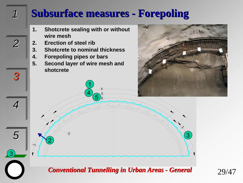
11 SubsurfaceSubsurface measures measures -- ForepolingForepoling1. Shotcrete sealing with or without
wire mesh2. Erection of steel rib3. Shotcrete to nominal thickness4. Forepoling pipes or bars5. Second layer of wire mesh and
shotcrete
1
2
3
3
45

30/30/4747Conventional TunneConventional Tunnellling in Urban Areas ling in Urban Areas -- GeneralGeneral
SpecialSpecial measures measures -- ForepolingForepoling
22
33
44
55
11
Rock bolts, length 6m
Rock bolts, length 4m Forepoling bars, length 6m, ø 25mm
Top Heading
BenchInvert Top Heading min. 25m ahead
Max. depends on ground conditions

31/31/4747Conventional TunneConventional Tunnellling in Urban Areas ling in Urban Areas -- GeneralGeneral
22
33
44
55
11 CrownCrown support support –– ForepoledForepoled umbrella (pipeumbrella (pipe roofroof))Method Area of
utilizationDescription Plants &
equipmentPipe roof without grouting
soils and rocks hardly grout able up to non-grout able
Horizontal predrilling, steel pipes driving-in Ø60-200mm, length up to30mPipes inner concreting
Drill jumbo, driving equipment
Pipe roof with grouting
soils and rocks easily grout able up to non-grout able
Horizontal predrilling, iron pipes driving-in Ø60-200mm, length till30m
Drill jumbo, driving equipment, grouting unit
Pipe roof with Jet Grouting
heterogeneticsoils with various distribution ofgrains
Horizontal predrilling, high-pressure grouting simultaneouslyexecuted with pullingout drilling rod Ø 0,5m to 1,0m, length up to15m, overlap 3 to 5m
Drill jumbo, drilling platform, high-pressure equipment(pump, mixer, feeder), datamonitoring equipment

32/32/4747Conventional TunneConventional Tunnellling in Urban Areas ling in Urban Areas -- GeneralGeneral
SpecialSpecial measures measures –– PipePipe RoofRoof
22
33
44
55
11
Rock bolts, length 6m
Length up to 30m, overlap 3 - 5m
Pipe RoofAngle app. 120º
Top Heading
BenchInvert
Driving direction

33/33/4747Conventional TunneConventional Tunnellling in Urban Areas ling in Urban Areas -- GeneralGeneral
22
33
44
55
11 JetJet Grouting Grouting –– exampleexampleinjectioninjection length 9m, length 9m, ØØ 60cm60cm
Top Heading – sand
Bench – silt
Invert - sandAdditionallysprayedshotcrete
Minnimum shotcrete thickness 20 cm under Jet Grouting piles

34/34/4747Conventional TunneConventional Tunnellling in Urban Areas ling in Urban Areas -- GeneralGeneral
22
33
44
55
11 JetJet Grouting Grouting –– exampleexampleinjectioninjection length 9m, length 9m, ØØ 60cm60cm
Minimum shotcrete thickness 20 cm under jet grouting piles
Top Heading – sand
Bench – silt
Invert - sand
35/35/4747Conventional TunneConventional Tunnellling in Urban Areas ling in Urban Areas -- GeneralGeneral
22
33
44
55
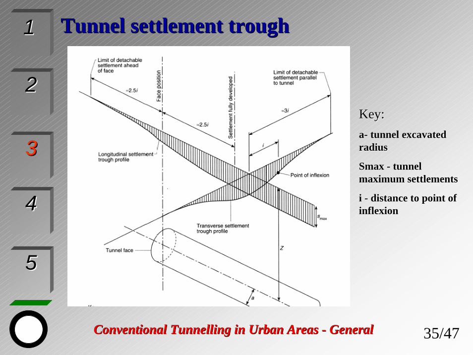
11 TunnelTunnel settlementsettlement troughtrough
Key:Key:aa-- tunneltunnel excavatedexcavatedradiusradius
Smax Smax -- tunnel tunnel maximum settlementsmaximum settlements
i i -- distance to point of distance to point of inflexioninflexion
36/36/4747Conventional TunneConventional Tunnellling in Urban Areas ling in Urban Areas -- GeneralGeneral
22
33
44
55
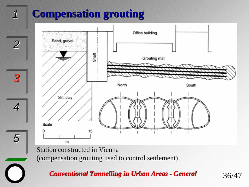
11 CompensationCompensation groutinggrouting
StationStation constructed in Vienna constructed in Vienna (compensation(compensation grouting used to controlgrouting used to control settlementsettlement))

37/37/4747Conventional TunneConventional Tunnellling in Urban Areas ling in Urban Areas -- GeneralGeneral
22
33
44
55
11 Geotechnical MonitoringGeotechnical MonitoringInstrumentation and measurement programs are an integral
part of tunnelling especially with NATM.
The objectives of measurements may comprise thefollowing:
• Verification of the design assumptions including the design model and design parameters
• Adjustment of the construction methods, supportsystems, and supplementary measures to the actualground conditions
• Minimization of construction hazards• Prevention of harmful impact to the environment
38/38/4747Conventional TunneConventional Tunnellling in Urban Areas ling in Urban Areas -- GeneralGeneral
22
33
44
55
11 Geotechnical Monitoring Geotechnical Monitoring -- ParametersParameters
Considering the specific requirements and stages of construction the following fields with parameters must beobserved:
• Ground water• Ground deformation• Soil – structure interaction• Observation of environment (adjacent buildings and
structures)• Progress monitoring

39/39/4747Conventional TunneConventional Tunnellling in Urban Areas ling in Urban Areas -- GeneralGeneral
22
33
44
55
11 Geotechnical Monitoring in Urban AreasGeotechnical Monitoring in Urban Areas
• Survey of building conditions before start of construction
• Measurement of settlements and heave
• Horizontal displacement
• Tilt measurement
• Vibration due to blasting
• Noise due to blasting, ventilation etc.

40/40/4747Conventional TunneConventional Tunnellling in Urban Areas ling in Urban Areas -- GeneralGeneral
22
33
44
55
11 Geotechnical Monitoring in Urban AreasGeotechnical Monitoring in Urban AreasLocation of Tunnelling Face relative to Instrumentation Cross Section
Instrument Monitoring Frequency
InstrumentationCross Section
d
InstrumentationCross Section
e
Surface settlement reference points
Extensometer
Inclinometer
Piezometer
d > 50m Initial reading
d < 30m Once a day
e < 30m Once a day
e > 30m Once a week

41/41/4747Conventional TunneConventional Tunnellling in Urban Areas ling in Urban Areas -- GeneralGeneral
22
33
44
55
11 Geotechnical Monitoring in Urban AreasGeotechnical Monitoring in Urban AreasLocation of Tunnelling Face relative to Instrumentation Cross Section
Instrument Monitoring Frequency
InstrumentationCross Section
e InstrumentationCross Section
3D-Monitoring Pins
Pressure Cells (real time)
Initial reading immediately after installation at each subheading
e < 30m Once a day
e > 30m Once a week
Notes:The monitoring frequencies may be adjusted as requiredacc. to actual ground conditionsMonitoring frequency for real time pressure cells mustbe adjusted to the compensation grouting programme (if applied) as required

42/42/4747Conventional TunneConventional Tunnellling in Urban Areas ling in Urban Areas -- GeneralGeneral
22
33
44
55
11 Geotechnical ReportGeotechnical Report
Must include at least:
• Introduction
• Site information provided at the time of tender
• Ground conditions encountered during excavation
• Comparison between the expected and encountered ground conditions
• Conclusions

43/43/4747Conventional TunneConventional Tunnellling in Urban Areas ling in Urban Areas -- GeneralGeneral
Waterproofing and finalWaterproofing and final lininglining
22
33
44
55
11
Protection against groundwater – waterproofing
• Open (umbrella system) – waterproofing membranefrom PE or PVC protected with geotextile with pipedrainage (usually on sides of tunnel walls)
• Fully tanked system – waterproofing layer withoutpermanent pipe drainage in case when groundwaterlevel should not be affected by tunnel
• Double waterproofing divided into the sections by cross and longitudinal waterstop profiles especially fortunnels under groundwater level
44/44/4747Conventional TunneConventional Tunnellling in Urban Areas ling in Urban Areas -- GeneralGeneral
Waterproofing and finalWaterproofing and final lininglining
22
33
44
55
11
Final (secondary) lining
• Unreinforced concrete – usually for hard rock conditions and for vault shape and circular crosssections
• Reinforced concrete – for soft ground conditions, poor rock conditions and for special shape cross section (niches, laybies etc.)
• Reinforced watertight concrete with protection ofworking joints (e.g. waterstops) – for tunnels undergroundwater level

45/45/4747Conventional TunneConventional Tunnellling in Urban Areas ling in Urban Areas -- GeneralGeneral
Waterproofing and finalWaterproofing and final lininglining
22
33
44
55
11
ExampleExample ofof roadroad tunneltunnel withwithunreinforcedunreinforced finalfinal lining and openlining and openwaterproofingwaterproofing systemsystem withwith sidesidedrainagedrainage pipes (Branisko Tunnel, pipes (Branisko Tunnel, Slovakia)Slovakia)
ExampleExample ofof railrail tunneltunnel withwithreinforcedreinforced finalfinal lining (Zurich lining (Zurich --ThalwillThalwill Tunnel, Switzerland)Tunnel, Switzerland)
46/46/4747Conventional TunneConventional Tunnellling in Urban Areas ling in Urban Areas -- GeneralGeneral
Waterproofing and finalWaterproofing and final lininglining
22
33
44
55
11
• surface protection of lining using special plates• sufficient cover of steel reinforcement• polyprophylene fibres added to the concrete
mixture
Final lining from the fire protection point of view
Final lining is load – bearing element with permanentfunction. Fire in tunnel with very high temperaturescould cause collapse of lining. This could be verydangerous in case when buildings are situated abovethe tunnel.Various protective measures should be done for liningprotection:

47/47/4747Conventional TunneConventional Tunnellling in Urban Areas ling in Urban Areas -- GeneralGeneral
Conclusions and references
22
33
44
55
11
• Excavation stages must be sufficiently short, both in terms of dimensions and duration.
• Completion of primary support - in particular, closure of the shotcrete ring must not be delayed
Conventional tunnelling methods are widely usedvirtually in all types of ground conditions.The application of sprayed concrete primary support in soft ground tunnelling is relatively recent comparedwith its use in hard rock tunnelling. For tunnels in urban areas limiting settlements is of high importance to avoid damage to overlying structures. To achievethe essential limitation of settlement, the followingprincipal measures must be undertaken: