Embed Size (px)
Citation preview

CONVENTIONAL MACHINE
CONVENTIONAL MILLING MACHINE
• Milling is the process of cutting away material by feeding a work piece past a rotating multiple tooth cutter. • The cutting action of the many teeth around the milling cutter provides a fast method of machining. • The machined surface may be flat, angular, or curved. The surface may also be milled to any combination of shapes. • The machine for holding the work piece, rotating the cutter, and feeding it is known as the Milling machine.
-CLASSIFICATION OF MILLING
• Peripheral Milling In peripheral (or slab) milling, the milled surface is generated by teeth located on the periphery of the cutter body. The axis of cutter rotation is generally in a plane parallel to the work piece surface to be machined.
• Face Milling In face milling, the cutter is mounted on a spindle having an axis of rotation perpendicular to the work piece surface. The milled surface results from the action of cutting edges located on the periphery and face of the cutter. • End Milling The cutter in end milling generally rotates on an axis vertical to the work piece. It can be tilted to machine tapered surfaces. Cutting teeth are located on both the end face of the cutter and the periphery of the cutter body.

METHODS OF MILLING
• Up Milling Up milling is also referred to as conventional milling. The direction of the cutter rotation opposes the feed motion. For example, if the cutter rotates clockwise , the workpiece is fed to the right in up milling.
• Down Milling Down milling is also referred to as climb milling. The direction of cutter rotation is same as the feed motion. For example, if the cutter rotates counterclockwise , the work piece is fed to the right in down milling.
The chip formation in down milling is opposite to the chip formation in up milling. The figure for down milling shows that the cutter tooth is almost parallel to the top surface of the work piece. The cutter tooth begins to mill the full chip thickness. Then the chip thickness gradually decreases.

Other milling operations are shown in the figure.
• Parts of the centre milling.

There are two basic configurations of milling machine; horizontal and vertical. ‐ Plain horizontal milling
Illustrates a plain horizontal mill: A traversing slide moves (i) under the cutter providing the feed. Height adjustment (ii) sets the depth of cut. Movement (iii) is positional adjustment only and is set and usually locked before cutting commences. ‐ Vertical milling
Illustrates a vertical mill: Movements (i) and (iii) may both be used to provide cutting feed. Movement (ii) sets depth of cut.
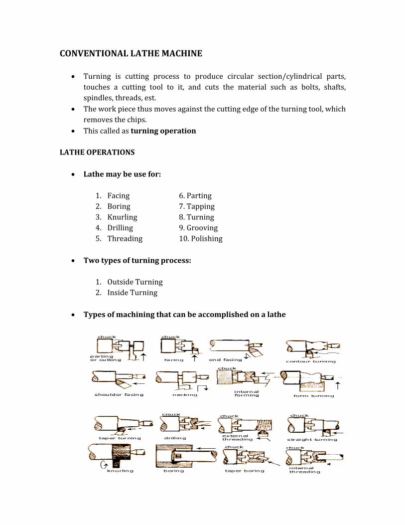
CONVENTIONAL LATHE MACHINE • Turning is cutting process to produce circular section/cylindrical parts, touches a cutting tool to it, and cuts the material such as bolts, shafts, spindles, threads, est. • The work piece thus moves against the cutting edge of the turning tool, which removes the chips. • This called as turning operation
LATHE OPERATIONS
• Lathe may be use for: 1. Facing 6. Parting 2. Boring 7. Tapping 3. Knurling 8. Turning 4. Drilling 9. Grooving 5. Threading 10. Polishing • Two types of turning process:
1. Outside Turning 2. Inside Turning • Types of machining that can be accomplished on a lathe

TYPES OF LATHE MACHINE • Parts of the centre lathe
• Types of turning tool
Cutting speed
• Cutting speed is the cutting length in meter per minute (m/min). • If the cutting speed is too low, the machining times will be too long. • If the cutting speed is too high , the cutting edge loses its hardness due to strong heating • The cutting edge wears out quickly and must often be reshaped.
V=π x d x n m/min where: V = cutting speed in m/min 1000 d = diameter of work piece n = revolution per minute (rpm)
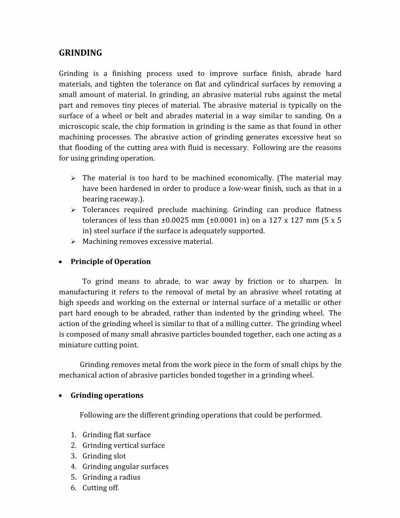
GRINDING Grinding is a finishing process used to improve surface finish, abrade hard materials, and tighten the tolerance on flat and cylindrical surfaces by removing a small amount of material. In grinding, an abrasive material rubs against the metal part and removes tiny pieces of material. The abrasive material is typically on the surface of a wheel or belt and abrades material in a way similar to sanding. On a microscopic scale, the chip formation in grinding is the same as that found in other machining processes. The abrasive action of grinding generates excessive heat so that flooding of the cutting area with fluid is necessary. Following are the reasons for using grinding operation. The material is too hard to be machined economically. (The material may have been hardened in order to produce a low‐wear finish, such as that in a bearing raceway.). Tolerances required preclude machining. Grinding can produce flatness tolerances of less than ±0.0025 mm (±0.0001 in) on a 127 x 127 mm (5 x 5 in) steel surface if the surface is adequately supported. Machining removes excessive material.
• Principle of Operation To grind means to abrade, to war away by friction or to sharpen. In manufacturing it refers to the removal of metal by an abrasive wheel rotating at high speeds and working on the external or internal surface of a metallic or other part hard enough to be abraded, rather than indented by the grinding wheel. The action of the grinding wheel is similar to that of a milling cutter. The grinding wheel is composed of many small abrasive particles bounded together, each one acting as a miniature cutting point. Grinding removes metal from the work piece in the form of small chips by the mechanical action of abrasive particles bonded together in a grinding wheel. • Grinding operations Following are the different grinding operations that could be performed. 1. Grinding flat surface 2. Grinding vertical surface 3. Grinding slot 4. Grinding angular surfaces 5. Grinding a radius 6. Cutting off.
TYPES OF GRINDING MACHINES: Grinding machines are designed principally for finishing parts having cylindrical, flat or internal surfaces. The kind of surface machined largely determines the type of grinding machine. Following is the classification of various types of grinding machines. 1. Surface grinding machine: It is a precision grinding machine to produce flat surfaces on a work piece. It is more economical and practical method of accurately finished flat surfaces than filling and scraping. The grinding is done on the circumference of the plain wheel. Area of contact is less. Following are the different types of surface grinders. In general, following are the parts of any grinding machine. Base: It has a driving mechanism (hydraulic device, tank and motor.) It has column at the back for supporting the wheel head. Saddle: It is the frame. It carries the table in its cross wise movement. It is used to give cross‐feed to the work. It can be moved by hand feed or auto‐feed. Table: It is fitted on the saddle. It reciprocates along the guide ways to prove the longitudinal feed to the work. It has 'T' slots for clamping purposes. It is moved by hand or auto‐feed. Wheel head: It is mounted on the column. It can be moved vertically up and down to accommodate work piece of different lengths. The wheel rotates at a constant speed of 1500 m / min.

Specification of surface grinder: • Maximum diameter of the wheel that can be held one the spindle. • Maximum size of the job that can be ground. • The type of drive of the work table ( Hydraulic / electrical )
2. Cylindrical grinder: It produces a cylindrical or conical shape on a work piece. The work piece is mounted between centers or in a chuck and the face of the grinding wheel passes over the external surface of the revolving work piece. There are two types of cylindrical grinders. They are Plain cylindrical grinders: These are the machines that are designed for simple external grinding. The wheel head is made to operate to and from the work table but cannot be swiveled. The work table holds the work head and tail stock and can be swiveled for slight
Horizontal spindle reciprocating table Horizontal spindle rotary
table Vertical spindle reciprocating table Vertical spindle rotary table
tapers. The head stock is rigidly attached to the work table and cannot be swiveled. It is located to the left of the operator. These grinders are used to produce • Plain or stepped surface, • External cylinders. • Tapers, • Concave or convex radii, • Under cuts and • Form grinding by dressing the grinding wheel the desired shape. Universal cylindrical grinders: It is different from the above grinder in the sense that the wheel head can be swiveled on its base and can be fed to and from the table. The upper work table can be swiveled and is equipped with scales and adjusting screws for setting the table to produce slight tapers. Steep tapers may be ground by swiveling the headstock on its base. The universal grinding machine is a tool room machine.
COMPUTER NUMERICAL CONTROL (CNC) A CAM technology using computers to control cutting machines such as milling machines and lathes to cut specified three‐dimensional shapes. CNC has been used since the early 1970s. Prior to this, machines were controlled by prepared tapes and the process was called simply Numerical Control (NC).
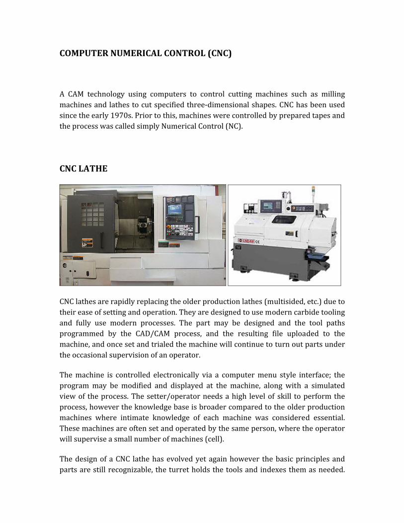
CNC LATHE
CNC lathes are rapidly replacing the older production lathes (multisided, etc.) due to their ease of setting and operation. They are designed to use modern carbide tooling and fully use modern processes. The part may be designed and the tool paths programmed by the CAD/CAM process, and the resulting file uploaded to the machine, and once set and trialed the machine will continue to turn out parts under the occasional supervision of an operator. The machine is controlled electronically via a computer menu style interface; the program may be modified and displayed at the machine, along with a simulated view of the process. The setter/operator needs a high level of skill to perform the process, however the knowledge base is broader compared to the older production machines where intimate knowledge of each machine was considered essential. These machines are often set and operated by the same person, where the operator will supervise a small number of machines (cell). The design of a CNC lathe has evolved yet again however the basic principles and parts are still recognizable, the turret holds the tools and indexes them as needed.
The machines are often totally enclosed, due in large part to Occupational health and safety (OH&S) issues. With the advent of cheap computers, free operating systems such as Linux, and open source CNC software, the entry price of CNC machines has plummeted.
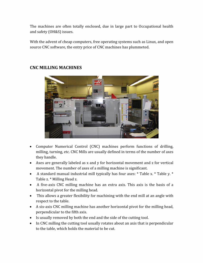
CNC MILLING MACHINES
• Computer Numerical Control (CNC) machines perform functions of drilling, milling, turning, etc. CNC Mills are usually defined in terms of the number of axes they handle. • Axes are generally labeled as x and y for horizontal movement and z for vertical movement. The number of axes of a milling machine is significant. • A standard manual industrial mill typically has four axes: * Table x. * Table y. * Table z. * Milling Head z. • A five‐axis CNC milling machine has an extra axis. This axis is the basis of a horizontal pivot for the milling head. • This allows a greater flexibility for machining with the end mill at an angle with respect to the table. • A six‐axis CNC milling machine has another horizontal pivot for the milling head, perpendicular to the fifth axis. • Is usually removed by both the end and the side of the cutting tool. • In CNC milling the cutting tool usually rotates about an axis that is perpendicular to the table, which holds the material to be cut.

• Cutting tools of various profile shapes include: i. Square ii. Rounded iii. Angled
• A wide variety of part shapes and geometries are possible by a CNC machine. • Interestingly, CNC machines come in various models, which range from small desk‐top lathes and milling machines to larger full‐sized machining centers. • CNC milling machines carry out the cutting process in which materials are removed from a block by a rotating tool. • In CNC milling, the cutting tool is moved in all three dimensions to achieve the desired cut shape. • A key advantage of CNC machining is the wide variety of work piece features that it can produce. • Part features such as walls, pockets of different depths, tapped holes, bolt‐hole circle patterns and others commonly found on prototypes can be precisely produced on a CNC machine. • One other advantage of CNC machines is their ability to produce metal molds which can then be used for injection molding operations.