Embed Size (px)
Citation preview

Controls Preliminary Design Report Issue 5.doc
Document
Prepared By:
Juan C. Delgadillo
Signature and Date:
27 May 2004
Document
Interpreted By:
John J. Johnson
Signature and Date: 27 May 2004
Document
Approved By:
Juan C. Delgadillo
Signature and Date:
27 May 2004
Document
Released By:
Juan C. Delgadillo
Signature and Date:
27 May 2004
Tel: +44 (0)131 668 8411 Fax: +44 (0)131 668 8412 Email: [email protected],
http://www.roe.ac.uk/atc/projects/vista/
Document Title: Controls System Design Report Document Number: VIS-ANA-VER-01001-9002 Issue: 5.0 Date: 27 May 2004
The information contained in this document is strictly confidential and is intended for the addressee only. The unauthorised use, disclosure, copying, alteration or distribution of this document is strictly prohibited and may be unlawful.
Doc Number: VIS-ANA-VER-01001-9002
Date: 27 May 2004
Issue: 5.0
Page: 2 of 80
Author: J. Delgadillo
Controls Preliminary Design Report Issue 5.doc
Change Record Issue Date Section(s) Affected Description of Change/Change Request
Reference/Remarks 1.0 08/08/03 All First Issue 2.0 08/20/03 Table 4.2.C Axis Limits, per RID No. TELS_PDR_29 2.0 08/20/03 4.2.2.4 Regeneration Cabinet, per RID No. TEL_PDR_24 2.0 08/20/03 4.2, Table 4.2.2.2.B and C AZ/ALT Initialisation, per RID No. TELS_PDR_40 2.0 08/20/03 Table 4.2.2.2.B and C,
Table 4.2.2.3.B PDU to LCU Interface, per RID No. TELS_PDR_51
2.0 08/20/03 4.2.2.7 Table Corrected power supply vendor and part number 2.0 08/20/03 3 Added AD10 reference 2.0 08/20/03 4.2.1 Revised LVD & EMC Table 3.0 08/28/03 4.2.2.1.9 Per TELS_PDR_79 RID, meaning of “disable” has been
clarified. 3.0 08/28/03 4.2.2.1.13 Per TELS_PDR_80 RID, LCU Mode section has been
amended. 3.0 08/28/03 4.2.2.9 Per TELS_PDR_38 RID, the PMU section has been
amended. 3.0 08/28/03 4.2.2.2 Per TELS_PDR_82 RID, correction to show that the Alt
rate feedback is the derivative of encoder feedback 3.0 08/30/03 4.2.2.2 Per TELS_PDR_105 RID, added Preload Scheme Plot 3.0 08/30/03 Table 4.2.C Per TELS_PDR_123 RID, AD03 calculations changed.
AD03 updated values are updated here. 3.0 08/31/03 Table 4.2.C Per TELS_PDR_104 RID, AD03 calculations changed.
AD03 updated values are updated here. 3.0 08/31/03 4.3.2 Per TELS_PDR_89 RID, the Altitude encoder-sitting
circumference updated. 3.0 08/31/03 Table 4.2.2.2.B and C,
Table 4.2.2.3.B Added Single Motor message per RID No. TELS_PDR_88
3.0 09/15/03 Table 4.2.2.2.B and C, Table 4.2.2.3.B
PDU to LCU Interface, per RID No. TELS_PDR_51 Contractor’s comments
3.0 09/15/03 4.2.2.2 AZ Bearing Lube Pump description, per RID No. TELS_PDR_22
3.0 09/15/03 4.2, 4.2.2.2, 4.2.2.3 Proposed LCU Interface change per RID No. TELS_PDR_40
3.0 09/15/03 4.2.2.2, 4.2.2.3, 4.2.2.6 Deletion of Overspeed Detection Unit on AZ and CASS axis (RID no. TELS_PDR_85 Contractor’s Updated Response)
3.0 09/16/03 4.2, 4.2.2.1, 4.2.2.9 Per RID No. TELS_PDR_55, moving MCU and PMU to an Appendix
3.0 09/17/03 Figure 4.2.A Updated Figure 4.2.A 4.0 03/17/04 ALL Extensive Revision to Include Final Design Changes 5.0 05/27/04 Signature Block Per TELS_FDR1_038, modified signature block signees 5.0 05/27/04 4.2.1 Per TELS_FDR1_039, clarified “Activate” terminology 5.0 05/27/04 Various Per TELS_FDR1_040, re -organized doc 5.0 05/27/04 4.2.5.1 6 Per TELS_FDR1_041, added AD11 and corrected
wording for Anemometer interfaces 5.0 05/27/04 4.2 Per TELS_FDR1_043, reworded function of MCU &
PMU 5.0 05/27/04 4.2.8 (new) Per TELS_FDR1_048, added para on break-out boxes 5.0 05/27/04 4.2.4.8, 4.2.5.14 Per TELS_FDR1_087, added Intlk signal to list and

Doc Number: VIS-ANA-VER-01001-9002
Date: 27 May 2004
Issue: 5.0
Page: 3 of 80
Author: J. Delgadillo
Controls Preliminary Design Report Issue 5.doc
corrected typo 5.0 05/27/04 Various Per TELS_FDR1_099, changed from Stow Pin
Extended to Stow Pin Engaged 5.0 05/27/04 4.2.5.16 Corrected part number for anemometers 5.0 05/27/04 4.3.2, 4.3.3 Updated Alt and CASS Encoder Tape calculations 5.0 05/27/04 4.2.2 Updated MCS Performance summary table per the
updated ADs

Doc Number: VIS-ANA-VER-01001-9002
Date: 27 May 2004
Issue: 5.0
Page: 4 of 80
Author: J. Delgadillo
Controls Preliminary Design Report Issue 5.doc
Table of Contents 1 INTRODUCTION..............................................................................................................................................6
2 ACRONYMS AND ABBREVIATIONS ........................................................................................................6
3 APPLICABLE AND REFERENCED DOCUMENTS................................................................................7
4 DESIGN REPORT.............................................................................................................................................8 4.1 SCOPE..........................................................................................................................................................8 4.2 DESIGN DESCRIPTION .................................................................................................................................8
4.2.1 Mount Control System Control Loops/Points of Control .................................................................16 4.2.2 MCS Performance Summary..............................................................................................................17 4.2.3 EU Electromagnetic and Safety Compatibility .................................................................................19 4.2.4 AZ/ALT Power Drive Unit..................................................................................................................21
4.2.4.1 AZ/ALT PDU Power Feeds..........................................................................................................21 4.2.4.2 AZ/ALT PDU Motor Controllers ..................................................................................................21 4.2.4.3 AZ/ALT PDU Lube System..........................................................................................................24 4.2.4.4 AZ/ALT PDU Status Board..........................................................................................................24 4.2.4.5 AZ/ALT Rate Loop Boards..........................................................................................................24 4.2.4.6 AZ/ALT Central Control Unit.......................................................................................................26 4.2.4.7 AZ/ALT Control Board ................................................................................................................27 4.2.4.8 AZ/ALT Interlocking ...................................................................................................................28 4.2.4.9 Altitude Manual Drive System......................................................................................................29 4.2.4.10 Altitude Imbalance .......................................................................................................................30 4.2.4.11 AZ/ALT PDU EMC Treatments ...................................................................................................30 4.2.4.12 AZ/ALT PDU Major Subassemblies.............................................................................................31 4.2.4.13 AZ/ALT LCU Interface ................................................................................................................31
4.2.5 CASS Power Drive Unit......................................................................................................................39 4.2.5.1 CASS PDU Motor Controllers ......................................................................................................39 4.2.5.2 CASS Cablewrap .........................................................................................................................39 4.2.5.3 CASS Interlocking .......................................................................................................................42 4.2.5.4 CASS PMU Control Logic ...........................................................................................................43 4.2.5.5 CASS Encoder Interface ...............................................................................................................43 4.2.5.6 CASS EMC Treatments................................................................................................................43 4.2.5.7 CASS Central Control Unit...........................................................................................................44 4.2.5.8 CASS Major Subassemblies .........................................................................................................45 4.2.5.9 CASS LCU Interface....................................................................................................................46 4.2.5.10 Regeneration Cabinet ...................................................................................................................48 4.2.5.11 Isolation Transformer ...................................................................................................................49 4.2.5.12 Data Acquisition System ..............................................................................................................51 4.2.5.13 Optical Incremental Tape Encoder................................................................................................53 4.2.5.14 AZ, ALT and CASS Drive Motors and Brakes ..............................................................................54 4.2.5.15 Mount Switches............................................................................................................................56 4.2.5.16 Anemometers...............................................................................................................................58
4.2.6 Material Parts .....................................................................................................................................59 4.2.7 Documentation ....................................................................................................................................59 4.2.8 Break-out Boxes ..................................................................................................................................59
4.3 TAPE ENCODER CALCULATIONS ..............................................................................................................60 4.3.1 Azimuth Tape Encoder Calculations .................................................................................................60 4.3.2 Altitude Tape Encoder Calculations ..................................................................................................60 4.3.3 Cassegrain Rotator Tape Encoder Calculations ..............................................................................61
4.4 CONCLUSIONS ...........................................................................................................................................62

Doc Number: VIS-ANA-VER-01001-9002
Date: 27 May 2004
Issue: 5.0
Page: 5 of 80
Author: J. Delgadillo
Controls Preliminary Design Report Issue 5.doc
APPENDIX A - MOUNT CONTROL UNIT ........................................................................................................64
APPENDIX B - PORTABLE MAINTENANCE UNIT .......................................................................................72
APPENDIX C - AZ/ALT AND CASS CENTRAL CONTROL UNIT .............................................................75

Doc Number: VIS-ANA-VER-01001-9002
Date: 27 May 2004
Issue: 5.0
Page: 6 of 80
Author: J. Delgadillo
Controls Preliminary Design Report Issue 5.doc
1 Introduction
This Design Report summarises the design features of the Vista Mount Control System for all contract items subject of this contract. This Design Report addresses every applicable requirement specified in the AD01 Technical Specification to the item that is the subject of this Design Report.
2 Acronyms and Abbreviations
ALT Altitude axis AM Amplitude Modulation AZ Azimuth axis AZ/ALT PDU Azimuth/Altitude Power Drive Unit CASS Cassegrain Rotator axis CASS PDU Cassegrain Power Drive Unit CB Circuit Breaker CCU Central Control Unit CCW Counter Clockwise CW Clockwise CFE Customer Furnished Equipment DAC Digital to Analogue Converter DAQ Data Acquisition Unit DSP Digital Signal Processor DVM Digital Volt Meter EMC Electromagnetic Compatibility EMI Electromagnetic Interference ESD Electrostatic Discharge EU European Union FOG Fiber Optic Gyroscope LCD Liquid Crystal Display LCU Local Control Unit LVD Low Voltage Directive LVDT Linear Variable Differential Transformer MCU Mount Control Unit MCS Mount Control System MTBF Mean Time Between Failures PMU Portable Maintenance Unit PWB Printed Wiring Board TFT Thin Film Transistor VER VertexRSI VIS VISTA VISTA Visible and Infrared Survey Telescope for Astronomy VPO VISTA Project Office TRE Technical Report

Doc Number: VIS-ANA-VER-01001-9002
Date: 27 May 2004
Issue: 5.0
Page: 7 of 80
Author: J. Delgadillo
Controls Preliminary Design Report Issue 5.doc
3 Applicable and Referenced Documents
In this section all the documents referred to in the Design Report shall be listed. Title Number & Issue
AD01 Technical Specification for the
Telescope Structure Work-Package VIS-SPE-ATC-01000-0006 Issue 3.0
AD02
Statement of Work for the VISTA Telescope Work Package
VIS-SOW-ATC-01000-0005 Issue 2.0
AD03 Motor and Brake Sizing Analysis
Report VIS-ANA-VER-01001-9003 Issue 4.0
AD04 Pointing and Tracking Analysis
Report VIS-TRE-VER-01001-9001 Issue 2.0
AD05 VISTA Control System & M1 Mirror Support Reliability and Availability Analysis Report
VIS-ANA-VER-01001-9004 Issue 3.0
AD06 Interface Control Document between the Electro-mechanical Hardware and the VISTA Control System
VIS-ICD-ATC-01000-0007 Draft Version 9.3
AD07
VLT Electronic Design Specification
VLT-SPE-ESO-10000-0015 Issue 5.0
AD08
Control System Power Budget Analysis Report
VIS-ANA-VER-01001-9005 Issue 4.0
AD09
VISTA Telescope Control System Simulation
VIS-ANA-VER-01001-9009 Issue 2.0
AD10
Electromagnetic Compatibility and Power Quality Specification, Part 2, Electromagnetic Disturbance Emission and Immunity Limits of Electric and Electronic Equipment
VLT-SPE-ESO-10000-0003 Issue 1.0

Doc Number: VIS-ANA-VER-01001-9002
Date: 27 May 2004
Issue: 5.0
Page: 8 of 80
Author: J. Delgadillo
Controls Preliminary Design Report Issue 5.doc
4 Design Report
4.1 Scope This design report will summarise the design features of all of the sub-assemblies that comprise the Vista MCS in enough detail to demonstrate compliance with the technical specifications, AD01.
4.2 Design Description The following Vista Cable Diagram, Figure 4.2.A, VPO drawing number VIS-DWG-VER-01001-9004, shows the equipment that comprises the VISTA Mount Control System. It denotes what is to be provided by VertexRSI Controls Division, VertexRSI Structures Division and what is provided by CFE (VPO or others). The major sub-assemblies of the MCS are:
AZ/ALT Power Drive Unit (AZ/ALT PDU) CASS Power Drive Unit (CASS PDU) Regeneration Cabinet Isolation Transformer Data Acquisition System Optical Incremental Tape Encoders AZ, ALT and CASS Drive Motors and Brakes Interlock Switches (Travel Limits, Stow switches, Emergency Stops, etc) Mount Control Unit (MCU) Portable Maintenance Unit (PMU)
The equipment will be located in the following areas: Equipment Room
AZ/ALT PDU, CASS PDU, Regeneration Cabinet, Isolation Transformer MCU and Emergency Stop Panel – These units, along with the AZ, ALT and CASS LCUs will reside in the VertexRSI provided standard 19” equipment rack (AD01 7.6, 11.1.1 spec)
Inside Yoke Arm Data Acquisition Unit M1 Mirror Support LCU Pedestal Mount Remaining equipment
The MCU and the PMU are not part of the system being delivered to meet the requirements of AD01 and AD02, and thus can be considered as test equipment. For this reason the units’ descriptions have been placed in Appendixes.

Doc Number: VIS-ANA-VER-01001-9002
Date: 27 May 2004
Issue: 5.0
Page: 9 of 80
Author: J. Delgadillo
Controls Preliminary Design Report Issue 5.doc
FIGURE 4.2.A – VISTA MOUNT CONTROL SYSTEM BLOCK DIAGRAM

Doc Number: VIS-ANA-VER-01001-9002
Date: 27 May 2004
Issue: 5.0
Page: 10 of 80
Author: J. Delgadillo
Controls Preliminary Design Report Issue 5.doc

Doc Number: VIS-ANA-VER-01001-9002
Date: 27 May 2004
Issue: 5.0
Page: 11 of 80
Author: J. Delgadillo
Controls Preliminary Design Report Issue 5.doc

Doc Number: VIS-ANA-VER-01001-9002
Date: 27 May 2004
Issue: 5.0
Page: 12 of 80
Author: J. Delgadillo
Controls Preliminary Design Report Issue 5.doc

Doc Number: VIS-ANA-VER-01001-9002
Date: 27 May 2004
Issue: 5.0
Page: 13 of 80
Author: J. Delgadillo
Controls Preliminary Design Report Issue 5.doc

Doc Number: VIS-ANA-VER-01001-9002
Date: 27 May 2004
Issue: 5.0
Page: 14 of 80
Author: J. Delgadillo
Controls Preliminary Design Report Issue 5.doc

Doc Number: VIS-ANA-VER-01001-9002
Date: 27 May 2004
Issue: 5.0
Page: 15 of 80
Author: J. Delgadillo
Controls Preliminary Design Report Issue 5.doc
Doc Number: VIS-ANA-VER-01001-9002
Date: 27 May 2004
Issue: 5.0
Page: 16 of 80
Author: J. Delgadillo
Controls Preliminary Design Report Issue 5.doc
Connectorized interconnection cabling will be provided for the MCS, including the cabling for the LCUs (AZ, ALT and CASS) (AD01 11.1.1 spec). The interconnection cables, as well as the hook-up cables (internal to the subassemblies) will be halogen free (AD07 4.3.1.3.1 spec), and in conformance with the applicable DIN, VDE, IEC standards for cable construction and tests. The signal cables will be colour coded per DIN 47100 (AD07 4.3.1.3.1 spec). The power cable conductors (1.5 mm2 - 6 mm2) will have black colour insulation marked with white numbers which identif ies the conductor. The mains power hook up cables inside the subassemblies will be colour coded per DIN VDE 0293 as follows: φ A Black φ B Brown φ C Black 3φN Blue 3φG Yellow/Green 1φL Brown 1φN Blue G Yellow/Green The AZ/ALT and the CASS PDU signal and low power connectors will be the MIL-C-38999, Series III type which offers the highest performance capabilities. The high power connectors will be the MIL-C-5015 type. EMI/RFI connector back-shells will be used (Mil Standard M85049) to provide excellent grounding of the cables’ overall shield. This will provide excellent attenuation of any radiated emissions.
4.2.1 Mount Control System Control Loops/Points of Control
Figure 4.2.B, VISTA Control Loop Block Diagram, shows in block diagram format, the VISTA nested loops: Position, Rate and Current (Torque). The block diagram also depicts the three points of control for the mount: LCU, MCU and PMU. Since the MCU and PMU are not part of the system being delivered to meet the requirements of AD01 and AD02, these units can be considered test equipment. As can be seen from Figure 4.2.B, when the MCU is in control, it issues Position Commands, when the LCU is in control it issues Velocity Commands, and when the PMU is in control it issues Velocity Commands. By default, the LCUs will be offered control of the system. Once a unit takes control, the off-line units cannot acquire control until the on-line unit relinquishes control. A manual, mechanical switch in the AZ/ALT and in the CASS PDU will be used to Activate (allow the LCUs to take control of the mount) the LCUs. Once in control of their respective axis, LCU motor enables/disables and rate demands can be successfully issued independently. When the switch is placed to the alternate position, the LCUs relinquish control of the mount.

Doc Number: VIS-ANA-VER-01001-9002
Date: 27 May 2004
Issue: 5.0
Page: 17 of 80
Author: J. Delgadillo
Controls Preliminary Design Report Issue 5.doc
FIGURE 4.2.B – VISTA CONTROL LOOP BLOCK DIAGRAM
4.2.2 MCS Performance Summary
Following is a summary of mount performance requirements:
TABLE 4.2.C - Performance Requirements
AD01 Spec VISTA SPECIFICATION MCS CAPABILITY 8.3 Axis Velocities and Accelerations
AZ Velocity +/- 2°/sec ALT Velocity +/- 2°/sec CASS Velocity +/- 3.6 °/sec AZ Acceleration +/- 0.5 °/sec2 ALT Acceleration +/- 0.5 °/sec2
CASS Acceleration +/- 1.0 °/sec2
(Refer to AD03) AZ Velocity +/- 2°/sec ALT Velocity +/- 2°/sec CASS Velocity +/- 3.6 °/sec AZ Acceleration +/- 1.0 °/sec2 ALT Acceleration +/- 1.0 °/sec2
CASS Accel +/- 2.5 °/sec2 8.5.2 Open Loop Tracking
0.10 arcsec rms over 15 secs 0.25 arcsec rms over 5 min
(Refer to AD04) 0.070 arcsec rms over 15 sec 0.217 arcsec rms over 5 min

Doc Number: VIS-ANA-VER-01001-9002
Date: 27 May 2004
Issue: 5.0
Page: 18 of 80
Author: J. Delgadillo
Controls Preliminary Design Report Issue 5.doc
AD01 Spec VISTA SPECIFICATION MCS CAPABILITY 8.4.2 Quasi Static Pointing Error
Non-Repeatable Full Sky < 1.0 arcsec rms 0.17 deg < 0.1 arcsec rms 2 deg < 0.25 arcsec rms 60 deg < 0.5 arcsec rms Total Full Sky < 15 arcsec rms 0.17 deg < 0.1 arcsec rms 2 deg < 0.5 arcsec rms 60 deg < 8 arcsec rms
(Refer to AD04) Non-Repeatable 0.460 arcsec rms 0.087 arcsec rms 0.154 arcsec rms 0.460 arcsec rms Total 28.0arcsec rms 0.117 arcsec rms 1.02 arcsec rms 23.2 arcsec rms
10.5.2 Cass Tracking Requirements Non-Repeatable Full Sky 9.3 arcsec rms 60 deg 1.2 arcsec rms Total Full Sky 31 arcsec rms
(Refer to AD04) Non-Repeatable 0.68 arcsec rms 0.68 arcsec rms Total 10.02 arcsec rms
11.1.4.1 100 % CASS Motor Overhead
(Refer to AD03) 224 %
11.1.6 Encoder Resolution Azimuth < 0.01 arcsec Altitude < 0.01 arcsec Cass < 0.015 arcsec
(Refer to Calculation’s Section 4.5) Azimuth 0.003 arcsec Altitude 0.002 arcsec Cassegrain 0.003 arcsec
11.1.8.1 Axis Limits Vicinity AZ Not Specified ALT Not Specified CASS Not Specified Pre-Interlock AZ +140°, -320° ALT -1°, 91° CASS +188°, -368° Interlock AZ +144°, -324° ALT -2°, 92° CASS +192°, -372° End Stop AZ +148°, -328° ALT -4°, 94° CASS +196°, -376°
Vicinity AZ +140°, -320° ALT -1°, +91° CASS +188°, -368° Pre-Interlock AZ +141°, -321° ALT -2°, 92° CASS +189°, -369° Interlock AZ +142°, -322° ALT -3°, 93° CASS +190°, -370° End Stop AZ N/A ALT -5.8°, 96.8° CASS N/A

Doc Number: VIS-ANA-VER-01001-9002
Date: 27 May 2004
Issue: 5.0
Page: 19 of 80
Author: J. Delgadillo
Controls Preliminary Design Report Issue 5.doc
AD01 Spec VISTA SPECIFICATION MCS CAPABILITY 11.1.10 Braking Deceleration
AZ 4°/s2 to 60°/s2
ALT 8°/s2 to 60°/s2
CASS 16°/s2 to 120°/s2
(Refer to AD03) AZ 13.9 °/s2
ALT 5.9 °/s2
CASS 74.9 °/s2
13.2.1 Overall Availability
> 363 nights/yr (99.45 %) (Refer to AD05) 99.93 %
13.2.2 MTBF 3 years
(Refer to AD05) 8.8 months
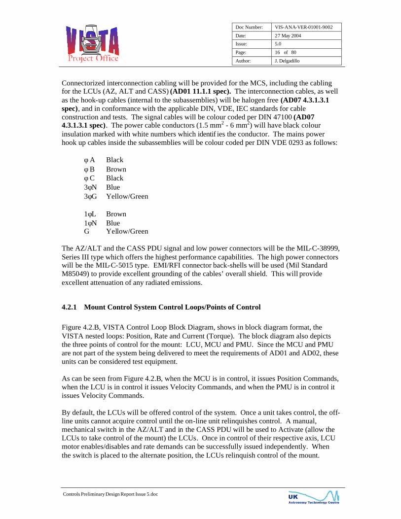
4.2.3 EU Electromagnetic and Safety Compatibility
The MCS will be compliant to the EU Council EMC (89/336/EEC) and Low Voltage Directives (73/23/EEC). Testing to the following standards and limits will show compliance to the EU Directives. The VLT AD10 limits will be a design goal, but compliance will be limited to the MCS stated limits.
Doc Number: VIS-ANA-VER-01001-9002
Date: 27 May 2004
Issue: 5.0
Page: 20 of 80
Author: J. Delgadillo
Controls Preliminary Design Report Issue 5.doc
TABLE 4.2.1 LVD & EMC Test Standards & Limits
STANDARD TITLE MCS LIMITS AD10 LIMITS
EN 50081, Part 2
Electromagnetic Compatibility – Generic Emission Standard Part 2: Industrial Environment (Class A)
CONDUCTED 0.15 – 0.5 MHz QP 79, AVG 66 dBµV 0.5 – 30 MHz QP 73, AVG 60 dBµV RADIATED (@ 10 m)
30 – 230 MHz 39.5 dB(µV/m) 230 – 1000 MHz 46.5 dB(µV/m)
CONDUCTED 0.15 – 0.5 MHz 66-56 dBµV QP 0.5 – 5 MHz 56 dBµV QP 5 – 30 MHz 60 dBµV QP RADIATED (10m)
30 – 230 MHz 30 dB(µV/m) 230 – 1000 MHz 37 dB(µV/m)
IEC 61000-4-2 Electromagnetic Compatibility – Part 4: Testing and Measurement Techniques – Part 2: Electrostatic Discharge (ESD) Immunity
LEVEL 2 4KV Contact Discharge
LEVEL 3 8KV Air Discharge
LEVEL 3 6KV Contact Discharge 8KV Air Discharge
IEC 61000-4-3 Electromagnetic Compatibility – Part 4: Testing and Measurement Techniques – Part 3: Radiated Radio-Frequency, Electromagnetic Field Immunity Test
LEVEL 2 80 to 1000 MHz 80% AM @ 1KHz 3 V/m
LEVEL 3 80 to 1000 MHz 80% AM @ 1KHz 10 V/m
IEC 61000-4-4 Electromagnetic Compatibility – Part 4: Testing and Measurement Techniques – Part 4: Electrical Fast Transient Immunity
LEVEL 2 0.5KV on I/O Signal and Control Lines 1KV on PS Lines
LEVEL 2 0.5KV on I/O Signal and Control Lines
1KV on PS Lines IEC 61000-4-5 Electromagnetic Compatibility – Part 4: Testing
and Measurement Techniques – Part 5: Surge Immunity
CLASS 2 Line to Earth 1KV Line to Line 0.5 KV
CLASS 3 Line to Earth 2KV Line to Line 1 KV
IEC 61000-4-6 Electromagnetic Compatibility – Part 4: Testing and Measurement Techniques – Part 6: Immunity to Conducted Disturbances, Induced by Radio-Frequency Fields
LEVEL 2 150 KHz to 80 MHz 3 Vrms 80% Mod.
Not Specified
IEC 61000-4-11 Electromagnetic Compatibility – Part 4: Testing and Measurement Techniques – Part 11: Immunity Requirement, Voltage Dips, Short Interruption and Voltage Variation
30% reduction (10ms) 60% reduction (100 ms) >95% reduction (5 sec)
30% reduction,10ms 50% reduction,0.1s >95% reduction,5sec
EN 61000-3-2 Electromagnetic Compatibility Part 3: Limits-Section 2: Limits for Harmonic Currents Emissions (Equipment Input Current <= 16A/phase)
Class A Limits Refer to Standard
Not Specified
EN 61000-3-3 Electromagnetic Compatibility Part 3: Limits-Section 3: Limitation of Voltage Fluctuations and Flicker in Low Voltage Supply Systems for Equipment with Rated Current <= 16A
Class A Limits Refer to Standard
Not Specifie d
Doc Number: VIS-ANA-VER-01001-9002
Date: 27 May 2004
Issue: 5.0
Page: 21 of 80
Author: J. Delgadillo
Controls Preliminary Design Report Issue 5.doc
4.2.4 AZ/ALT Power Drive Unit
Refer to the following representative photograph (Figure 4.2.2.1.A) and block diagram (Figure 4.2.2.1.B) of the AZ/ALT Power Drive Unit.
4.2.4.1 AZ/ALT PDU Power Feeds
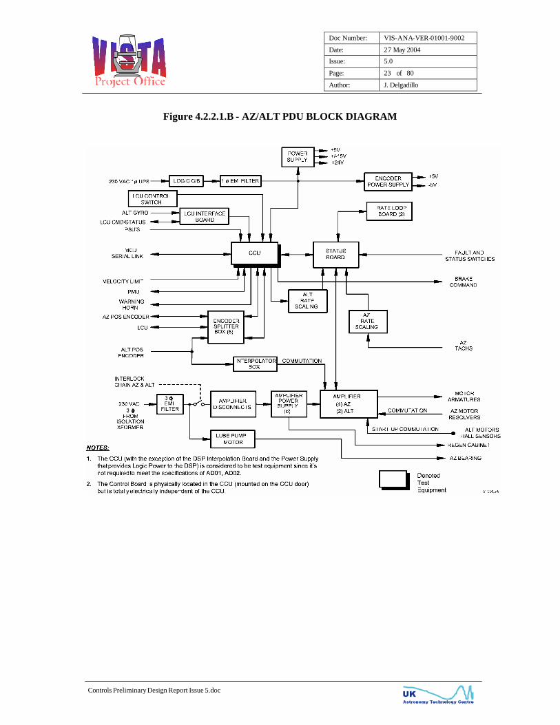
Two power feeds are utilized by the PDU. 230 VAC, 1φ technical power gets routed through the logic circuit breaker, a single phase EMI filter for attenuation of conducted emissions and to two universal input switching power supplies. The PDU logic power supply is a 100 W switching power supply that has multiple outputs for delivering logic power to the various PWBs and other components in the PDU. The encoder power comes from a 45W power supply that will deliver power to the 4 Azimuth and 4 Altitude tape encoder read-heads (AD01 11.1.6 g spec), to the Heidenhain Encoder Splitter boxes (IBV606) and to the Heidenhain Interpolator boxes (IBV660B). The Heidenhain IBV 606 Encoder Splitter boxes will be utilized to split the encoder read-head sinusoidal signals. One output will be dedicated for use by the AZ/ALT PDU. The second sinusoidal output will be routed over to the AZ and ALT LCUs.
The second power feed comes from the output of the VertexRSI provided isolation transformer, which is 230 VAC, 3φ, Y-configuration. The power goes through the motor controller power disconnects and into 6 individual 3-phase EMI filters feeding the Azimuth and Altitude motor controller power supplies. The motor controller power supplies use the 3φ voltages and convert it to a DC bus voltage that feeds the motor controllers.
4.2.4.2 AZ/ALT PDU Motor Controllers
The motor controllers, configured for Current (Torque) mode, are used to drive the four Azimuth and the two Altitude Brushless DC motors. For Azimuth, motor resolvers are used by the motor controllers for sinusoidal commutation (AD01 11.1.4.1 spec). For Altitude, at start-up, trapezoidal commutation is accomplished using the motor’s Hall Sensors (AD01 11.1.4.1 spec). Automatic switchover to sinusoidal commutation is done once a Hall Sensor transition index is received. A/B Incremental signals used for ALT motor’s sinusoidal commutation come from the output of the Heidenhain Interpolator box (IBV 660B). One interpolator box is used per motor controller. The IBV 660B Interpolator boxes convert the tape encoder read -head 1Vpp signal into incremental encoder signals with a 25-fold interpolation factor. This results in approximately 113,650 counts per motor pole pair.

Doc Number: VIS-ANA-VER-01001-9002
Date: 27 May 2004
Issue: 5.0
Page: 22 of 80
Author: J. Delgadillo
Controls Preliminary Design Report Issue 5.doc
Figure 4.2.2.1.A - AZ/ALT POWER DRIVE UNIT (Photo is Representative)
Doc Number: VIS-ANA-VER-01001-9002
Date: 27 May 2004
Issue: 5.0
Page: 23 of 80
Author: J. Delgadillo
Controls Preliminary Design Report Issue 5.doc
Figure 4.2.2.1.B - AZ/ALT PDU BLOCK DIAGRAM

Doc Number: VIS-ANA-VER-01001-9002
Date: 27 May 2004
Issue: 5.0
Page: 24 of 80
Author: J. Delgadillo
Controls Preliminary Design Report Issue 5.doc
The motor controllers are matched to, and thus ideally compensated to the brushless DC motors that they drive. The current loop bandwidth of the motor controllers has been measured to be around 800 Hz, which would easily satisfy the demanding outer axis rate loops. Resistive Regenerative units are connected to the motor controller power supply busses to dissipate the generated excess energy when the motors are being decelerated or back driven.
4.2.4.3 AZ/ALT PDU Lube System
The Azimuth bearing lube pump is energized from the AZ/ALT PDU. A pressure switch will detect and report a low-pressure fault. An overflow condition will be sensed by a level switch, which will report the fault. Both faults will be Disabling Faults of the Azimuth axis, but not of the lube pump motor power since the lube system has been designed to be ON at all times. Protection to the lube pump motor is provided via a thermal overload protection switch.
4.2.4.4 AZ/ALT PDU Status Board
The Status board provides extensive status and motor disabling capability. It interfaces to the AZ and ALT Rate Loop Boards, to the CCU Control Board and the motor controllers.
4.2.4.5 AZ/ALT Rate Loop Boards
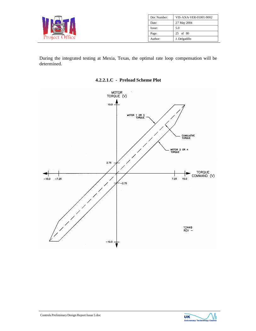
The Rate Loop boards receive rate demands from the Status board and rate feedback from the motor tachometers (AZ)/CCU Digital Signal Processor (ALT) to close the rate loop. The Rate Loop boards generate current commands, torque bias (AZ only) and delta tach control (AZ only). Torque bias is used by the Azimuth axis to remove any backlash in the gear train by counter-torquing two motors against the other two (refer to Figure 4.2.2.1.C for the preload scheme plot). It can be seen that the preload type is a constant differential preload up until saturation level. The preload level will be approximately 25% of motor rated torque. Delta tach circuitry ensures that motors run at the same speed, which results in load sharing. The rate loop compensation is similar to that of the MCU Position Loop. However, the Rate Loop compensation will be set-up as a Type II Loop. The following break frequencies will be the starting point for the VISTA system. Lag1 0.26 Hz Lead 1.59 Hz Lag2 19.03 Hz
Doc Number: VIS-ANA-VER-01001-9002
Date: 27 May 2004
Issue: 5.0
Page: 25 of 80
Author: J. Delgadillo
Controls Preliminary Design Report Issue 5.doc
During the integrated testing at Mexia, Texas, the optimal rate loop compensation will be determined.
4.2.2.1.C - Preload Scheme Plot
Doc Number: VIS-ANA-VER-01001-9002
Date: 27 May 2004
Issue: 5.0
Page: 26 of 80
Author: J. Delgadillo
Controls Preliminary Design Report Issue 5.doc
4.2.4.6 AZ/ALT Central Control Unit
Refer to the following AZ/ALT CCU Block Diagram, Figure 4.2.2.1.D. Only the CCU components that are required to meet the requirements of AD01 and AD02 are discussed in this section. The other components are considered test equipment and are discussed in Appendix C. Logic Power is supplied to the off-the-shelf Pentium motherboard from a universal input 300W switching power supply. The power supply supplies power to the Digital Signal Processor and the DSP Accessory 8E (18-bit DAC) board. The PDU Central Control Unit (CCU) houses the Digital Signal Processor and the DSP Accessory 8E (18-bit DAC) that are used to interface to the ALT Heidenhain Tape Encoder read-heads via the Heidenhain Encoder Splitter boxes (IBV606). The main function of the DSP is to produce the rate feedback information for the Altitude axis (AD01 11.1.7 a spec) via the 18-bit DAC board. The ALT rate feedback information, used to close the rate (velocity) loop is sent to the ALT Rate Loop board via the Status board. The rate feedback is the derivative of the tape encoder feedback. The software that produces the rate feedback resides in the DSP and is free running, meaning that once it has successfully booted, it doesn’t depend on any condition for the algorithm to start producing velocity feedback signals. This ALT rate feedback signal is also provided to the ALT LCU for monitoring purposes. A DSP on-board relay is used to monitor the health of the DSP. When the PMAC has successfully booted-up and is operational, the relay is energized. If the DSP becomes “locked-up”, the relay is de-energized. De-energizing of the relay results in the disabling of the ALT axis. A DSP Boot Failure would then get reported to the ALT LCU.

Doc Number: VIS-ANA-VER-01001-9002
Date: 27 May 2004
Issue: 5.0
Page: 27 of 80
Author: J. Delgadillo
Controls Preliminary Design Report Issue 5.doc
Figure 4.2.2.1.D - AZ/ALT PDU CCU BLOCK DIAGRAM
4.2.4.7 AZ/ALT Control Board
Although the Control board physically resides in the CCU, it is totally microprocessor and CCU independent. It provides an interface between the CCU computer (for monitoring purposes only) and external motor disabling connections to the mount structure. The Control board receives rate commands and enable requests from the LCU, MCU or the PMU and generates directional enables, axis rates, brake release commands and status/faults to all control units. The Control board also contains the acceleration/deceleration limiting circuitry and the soft-stop circuitry that enables a controlled deceleration before applying the brakes (when not in an emergency stop condition).
Doc Number: VIS-ANA-VER-01001-9002
Date: 27 May 2004
Issue: 5.0
Page: 28 of 80
Author: J. Delgadillo
Controls Preliminary Design Report Issue 5.doc
4.2.4.8 AZ/ALT Interlocking
As dictated by AD01 11.1.7 c spec, if any of the following isolated contacts open, 3-phase power is removed from the azimuth and/or altitude motor controllers, and will independently remove the brake release command. The Azimuth axis is composed of the following interlock chain:
Emergency Stops (AZ Motor 1-2, AZ Motor 3-4, Alt Motor 1, Alt Motor 2, Alt Pier, Equipment Room, and Cone E-stops)
AZ Positive/Negative Interlock Limit AZ Stow Pin Engaged AZ Overhead Dome Crane Interlock (AD01 13.4.12 b spec) Yoke Access Hatch Interlock AZ LCU Interlock Pier Access Interlock Mobile Access Platform Interlock
The Altitude axis is composed of the following interlock chain:
ALT Overspeed Emergency Stops (AZ Motor 1-2, AZ Motor 3-4, ALT Motor 1, ALT Motor 2, ALT
Pier, Equipment Room, and Cone E-stops) ALT Positive/Negative Interlock Limit ALT Stow Pin Engaged ALT Auxiliary Drive Enabled Interlock (AD01 11.1.12 spec) ALT Overhead Dome Crane Interlock (AD01 13.4.12 b spec) ALT LCU Interlock OSS Not Installed CASS Instrument not Installed M2 Unit not Installed M1 Mirror Restraint Failure Mobile Access Platform Interlock AZ Floor Access Interlock
Per the requirements of AD07, the LCU should have the capability to turn ON and OFF power to the motor controllers. VertexRSI will partially comply with this requirement. It will be possible for the LCUs to remove power to the motor controllers by issuing an Interlock command, but when power needs to be restored (after clearing the fault condition), it would need to be done by manually turning on the tripped circuit breakers in the Power Drive Unit. By having the operator physically switching back ON the circuit breakers that tripped, it ensures that the operator is made aware of the problem that caused the Interlock chain to break so that the appropriate remedial action can be made in order to avoid the situation again. This is in line with VertexRSI’s safety philosophy where software should not be allowed to clear a hardware condition. Furthermore, the design of the motor controller

Doc Number: VIS-ANA-VER-01001-9002
Date: 27 May 2004
Issue: 5.0
Page: 29 of 80
Author: J. Delgadillo
Controls Preliminary Design Report Issue 5.doc
call out for resetting its Logic Power (single-phase) after an Under Voltage fault occurs (occurring after removal of 3-phase power). That means that the Logic Power to the amplifier has to be cycled and the 3-phase CB has to be turned back on in order to clear (close) an auxiliary switch that the control system is sensing to ensure that the motor controller is ready for operation. To clarify, not only does the Interlock Chain turn off power to the amplifiers but also an internal motor controller fault (ie overspeed, over-voltage, under-voltage, over-current etc) would result in removing 3-phase power to itself. Additionally, external interlock circuitry to the motor controller ensures that the proper powering sequence of the motor controllers is maintained. It should also be mentioned, that regular activation (breaking) of the Interlock chain is highly not recommended since it compromises the reliability of the system. It’s widely known that frequent cycling of power to electronic equipment drastically reduces the life of the equipment. Due to the reliability issue mentioned above, it’s highly recommended that the Interlock chain not be broken except in emergency or maintenance conditions, as detected by the mount interlock switches (Emergency stops, Stow Pin Extended, etc). A second set of the above Interlock contacts is routed over to the LCUs for monitoring purposes only. A third set of the Interlock contacts is fed to the PDU Control or Status board for fault reporting and axis disabling. This serves as an added safety level of protection, satisfying the operational safety spec of AD01 13.4.11.
4.2.4.9 Altitude Manual Drive System
The Altitude axis will have an Auxiliary Manual Drive System (AD01 11.1.12 spec), which will Interlock the direct drive motors upon activation. The detection method will be via a switch that senses that the Auxiliary Manual Drive System has been removed from its cradle position. This would break the Interlock chain and set the Altitude pneumatic brakes. While in Alt Auxiliary Drive mode, brake release command can only be accomplished by activation of the Alt Manual Brake Release momentary switch. This would ensure that a minimum of two persons are involved in the manual movement of the Altitude axis.

Doc Number: VIS-ANA-VER-01001-9002
Date: 27 May 2004
Issue: 5.0
Page: 30 of 80
Author: J. Delgadillo
Controls Preliminary Design Report Issue 5.doc
4.2.4.10 Altitude Imbalance
Since the Altitude axis has direct drive (no gearing between motors and axis) torquer motors, the Altitude axis is very susceptible to imbalance, a potential risk for personnel and/or hardware damage. In order to mitigate the risk, the following design has been implemented on the VISTA Mount Control System:
1. Stow cradles will be slotted to allow for a manual altitude imbalance check. When the Alt axis is stowed, the Alt axis manual brake release button can be actuated and a mechanical verification of the axis imbalance can be achieved.
2. An M2 Unit Not Installed switch will detect when the M2 mirror has been
removed. If the M2 mirror if not present, the Alt axis will be Interlocked.
3. A Cassegrain Rotator Instrument not Installed switch will detect when the CASS has been removed resulting in the Interlocking of the Altitude axis.
4. An Optical Support Structure (OSS) switch will detect when the OSS has been
removed. In this condition, the Altitude axis will be Interlocked. The M1 Mirror Support system implements a scheme where the M1 Mirror is restrained when the ALT axis is below 20 degrees. For redundancy, two separate switches monitor the position of the ALT axis. If it is detected that the ALT axis is below 20° and the restraining system hasn’t clamped the M1 Mirror, the Altitude axis is Interlocked.
4.2.4.11 AZ/ALT PDU EMC Treatments
The following AZ/ALT PDU design features will ensure that the discussed EU EMC standards are met: Properly Shielded Conductive Gasketed Cabinets Completely Connectorized PDU Enclosure EMI/RFI Connector Bachshells Properly terminated Shielded Cables Motor Lead Ferrite Filters 1φ and 3φ EMI Filters

Doc Number: VIS-ANA-VER-01001-9002
Date: 27 May 2004
Issue: 5.0
Page: 31 of 80
Author: J. Delgadillo
Controls Preliminary Design Report Issue 5.doc
4.2.4.12 AZ/ALT PDU Major Subassemblies
The major subassemblies that make up the AZ/ALT PDU are listed below:
TABLE 4.2.2.1.A - AZ/ALT PDU Major Subassemblies
MANUFACTURER MANUFACTURER PART NUMBER
DESCRIPTION
Kollmorgen Motion Technologies Group
SR30200 PA2800
Azimuth Motor Controller and Power Supply
Kollmorgen Motion Technologies Group
SE30200 PA2800
Altitude Motor Controller and Power Supply
Hoffman PROLINE Series AZ/ALT PDU Enclosure Heidenhain IBV660B ALT Interpolator Box Heidenhain IBV 606 AZ/ALT Encoder Splitter
Box Integrated Power Design SRW-100-4003 PDU Logic Power Supply Integrated Power Design SRW-45-2002 Encoder Power Supply Finder Various Relays Sprecher + Schuh CS4C Series Contactors ABB Control Inc. Various Circuit Breakers Schaffner FN258-30/33 AZ/ALT 3φ EMI Filter Schaffner FN350-12/29 1φ EMI Filter Entrelec Inc. Various Time Delay Relays Wieland DPST-8A/125 Power Switch Shuttle Computer Group G7VP2 CCU Motherboard Delta Tau Turbo PMAC2-PC DSP Card Delta Tau Accessory 51P High Resolution Interpolator
Card Delta Tau Accessory 8E DSP DAC Accessory Bd Antron SP2-4300FB CCU Power Supply
4.2.4.13 AZ/ALT LCU Interface
Refer to Figure 4.2.2.1.E, LCU Interface Block Diagram, it shows the handshaking, status, command and feedback information between the AZ/ALT PDU and to the AZ and ALT LCU. As mentioned earlier, the accepting/relinquishing handshaking is done from a manual, mechanical switch located in the AZ/ALT PDU. After the AZ/ALT LCUs have control of the mount, individual axis enables/disables can be issued independently.

Doc Number: VIS-ANA-VER-01001-9002
Date: 27 May 2004
Issue: 5.0
Page: 32 of 80
Author: J. Delgadillo
Controls Preliminary Design Report Issue 5.doc
Figure 4.2.2.1.E - LCU Interface Block Diagram
AD07 dictates that galvanic isolation is maintained between VertexRSI and LCU equipment. This is accomplished by the use of dry-contact closure for digital signals and the use of Isolation Amplifiers for analogue signals. Please refer to Figure 4.2.2.1.F - LCU Axis Control Logic Block Diagram. The LCU Interface board accepts a pulsed signal required by the Flip -Flop logic of the Control Board. Isolation Amplifiers will be used for the LCU-generated (rate commands) and the PDU-generated analogue signals (rate and current feedback).

Doc Number: VIS-ANA-VER-01001-9002
Date: 27 May 2004
Issue: 5.0
Page: 33 of 80
Author: J. Delgadillo
Controls Preliminary Design Report Issue 5.doc
Figure 4.2.2.1.F - LCU Axis Control Logic Block Diagram

Doc Number: VIS-ANA-VER-01001-9002
Date: 27 May 2004
Issue: 5.0
Page: 34 of 80
Author: J. Delgadillo
Controls Preliminary Design Report Issue 5.doc
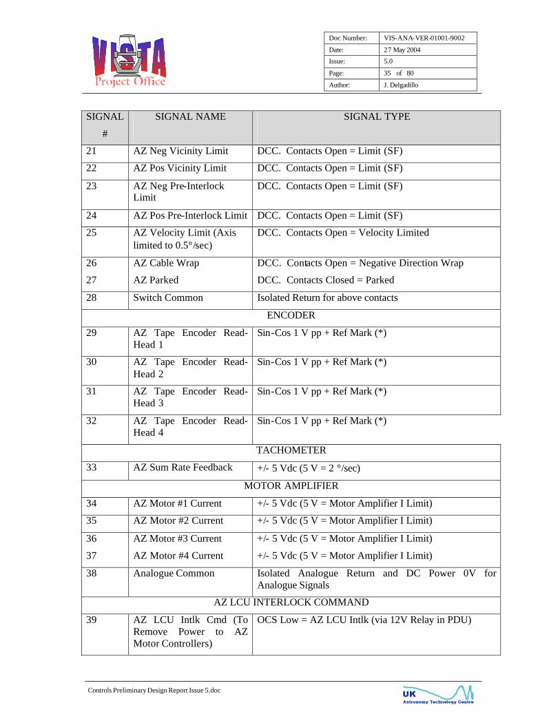
Following are the AZ/ALT PDU to Azimuth LCU interfaces.
TABLE 4.2.2.1.B - AZ/ALT PDU to AZ LCU Interfaces
SIGNAL
#
SIGNAL NAME
SIGNAL TYPE
CONTROL COMMAND-STATUS
1 AZ Rate Demand +/- 5 Vdc, +VE = +VE rate
2 AZ Rate Scale Factor OCS Low = 2.0 deg/s, High = 0.2 deg/s
3 AZ Enable Command OCS Low = AZ Enable
4 12V Relay +12V DC Relay power (For items 2,3,40)
5 AZ Actual Rate Scale factor
DCC. Contacts Open = 2.0 deg/s, Closed = 0.2 deg/s
6 AZ LCU Available DCC. Contacts Closed = AZ LCU Available
7 AZ LCU Enabled DCC. Contacts Closed = AZ LCU Enabled
8 AZ LCU Active DCC. Contacts Closed = AZ LCU Active
9 AZ Axis Enabled DCC. Contacts Closed = AZ Axis Enabled
10 AZ Summary Fault DCC. Contacts Open = AZ Disabled
11 Status Common Isolated Return for above contacts
RELAYS
12 AZ Brakes Released DCC. Contacts Closed = Brakes Released
13 AZ Neg-Pos Interlock Limit
DCC. Contacts Open = Limit (I)(SF)
14 AZ-ALT CCU Off DCC. Contacts Open = CCU Off
15 Yoke Access Hatch Open Intlk
DCC. Contacts Open = Hatch Open Intlk (I)(SF)
16 AZ Stow Pin Engaged Intlk
DCC. Contacts Open = Pin Extended Intlk (I)(SF)
17 Dome Crane Interlock AZ DCC. Contacts Open = Crane Intlk (I)(SF)
18 Pier Access Interlock DCC. Contacts Open = Access Intlk (I)(SF)
19 Mobile Access Platform Interlock
DCC. Contacts Open = Platform INLTK (I)(SF)
20 Relay Common Isolated Return for above contacts
SWITCHES
Doc Number: VIS-ANA-VER-01001-9002
Date: 27 May 2004
Issue: 5.0
Page: 35 of 80
Author: J. Delgadillo
Controls Preliminary Design Report Issue 5.doc
SIGNAL
#
SIGNAL NAME
SIGNAL TYPE
21 AZ Neg Vicinity Limit DCC. Contacts Open = Limit (SF)
22 AZ Pos Vicinity Limit DCC. Contacts Open = Limit (SF)
23 AZ Neg Pre-Interlock Limit
DCC. Contacts Open = Limit (SF)
24 AZ Pos Pre-Interlock Limit DCC. Contacts Open = Limit (SF)
25 AZ Velocity Limit (Axis limited to 0.5°/sec)
DCC. Contacts Open = Velocity Limited
26 AZ Cable Wrap DCC. Contacts Open = Negative Direction Wrap
27 AZ Parked DCC. Contacts Closed = Parked
28 Switch Common Isolated Return for above contacts
ENCODER
29 AZ Tape Encoder Read-Head 1
Sin-Cos 1 V pp + Ref Mark (*)
30 AZ Tape Encoder Read-Head 2
Sin-Cos 1 V pp + Ref Mark (*)
31 AZ Tape Encoder Read-Head 3
Sin-Cos 1 V pp + Ref Mark (*)
32 AZ Tape Encoder Read-Head 4
Sin-Cos 1 V pp + Ref Mark (*)
TACHOMETER
33 AZ Sum Rate Feedback +/- 5 Vdc (5 V = 2 °/sec)
MOTOR AMPLIFIER
34 AZ Motor #1 Current +/- 5 Vdc (5 V = Motor Amplifier I Limit)
35 AZ Motor #2 Current +/- 5 Vdc (5 V = Motor Amplifier I Limit)
36 AZ Motor #3 Current +/- 5 Vdc (5 V = Motor Amplifier I Limit)
37 AZ Motor #4 Current +/- 5 Vdc (5 V = Motor Amplifier I Limit)
38 Analogue Common Isolated Analogue Return and DC Power 0V for Analogue Signals
AZ LCU INTERLOCK COMMAND
39 AZ LCU Intlk Cmd (To Remove Power to AZ Motor Controllers)
OCS Low = AZ LCU Intlk (via 12V Relay in PDU)
Doc Number: VIS-ANA-VER-01001-9002
Date: 27 May 2004
Issue: 5.0
Page: 36 of 80
Author: J. Delgadillo
Controls Preliminary Design Report Issue 5.doc
SIGNAL
#
SIGNAL NAME
SIGNAL TYPE
ISOLATION AMPLIFIER POWER SUPPLIES
40 +12V DC Low Voltage Power (0V on item 38)
41 -12V DC Low Voltage Power (0V on item 38)
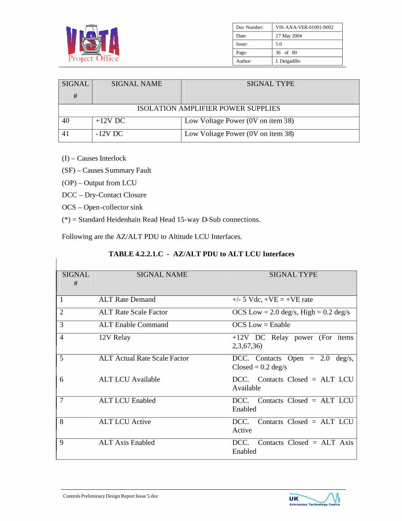
(I) – Causes Interlock
(SF) – Causes Summary Fault
(OP) – Output from LCU
DCC – Dry-Contact Closure
OCS – Open-collector sink
(*) = Standard Heidenhain Read Head 15-way D-Sub connections. Following are the AZ/ALT PDU to Altitude LCU Interfaces.
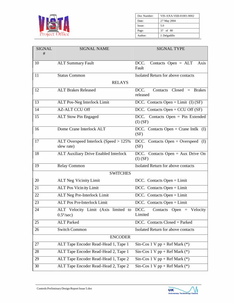
TABLE 4.2.2.1.C - AZ/ALT PDU to ALT LCU Interfaces
SIGNAL #
SIGNAL NAME
SIGNAL TYPE
1 ALT Rate Demand +/- 5 Vdc, +VE = +VE rate
2 ALT Rate Scale Factor OCS Low = 2.0 deg/s, High = 0.2 deg/s
3 ALT Enable Command OCS Low = Enable
4 12V Relay +12V DC Relay power (For items 2,3,67,36)
5 ALT Actual Rate Scale Factor DCC. Contacts Open = 2.0 deg/s, Closed = 0.2 deg/s
6 ALT LCU Available DCC. Contacts Closed = ALT LCU Available
7 ALT LCU Enabled DCC. Contacts Closed = ALT LCU Enabled
8 ALT LCU Active DCC. Contacts Closed = ALT LCU Active
9 ALT Axis Enabled DCC. Contacts Closed = ALT Axis Enabled
Doc Number: VIS-ANA-VER-01001-9002
Date: 27 May 2004
Issue: 5.0
Page: 37 of 80
Author: J. Delgadillo
Controls Preliminary Design Report Issue 5.doc
SIGNAL #
SIGNAL NAME
SIGNAL TYPE
10 ALT Summary Fault DCC. Contacts Open = ALT Axis Fault
11 Status Common Isolated Return for above contacts
RELAYS
12 ALT Brakes Released DCC. Contacts Closed = Brakes released
13 ALT Pos-Neg Interlock Limit DCC. Contacts Open = Limit (I) (SF)
14 AZ-ALT CCU Off DCC. Contacts Open = CCU Off (SF)
15 ALT Stow Pin Engaged DCC. Contacts Open = Pin Extended (I) (SF)
16 Dome Crane Interlock ALT DCC. Contacts Open = Crane Intlk (I) (SF)
17 ALT Overspeed Interlock (Speed > 125% slew rate)
DCC. Contacts Open = Overspeed (I) (SF)
18 ALT Auxiliary Drive Enabled Interlock DCC. Contacts Open = Aux Drive On (I) (SF)
19 Relay Common Isolated Return for above contacts
SWITCHES
20 ALT Neg Vicinity Limit DCC. Contacts Open = Limit
21 ALT Pos Vicin ity Limit DCC. Contacts Open = Limit
22 ALT Neg Pre-Interlock Limit DCC. Contacts Open = Limit
23 ALT Pos Pre-Interlock Limit DCC. Contacts Open = Limit
24 ALT Velocity Limit (Axis limited to 0.5°/sec)
DCC. Contacts Open = Velocity Limited
25 ALT Parked DCC. Contacts Closed = Parked
26 Switch Common Isolated Return for above contacts
ENCODER
27 ALT Tape Encoder Read-Head 1, Tape 1 Sin-Cos 1 V pp + Ref Mark (*)
28 ALT Tape Encoder Read-Head 2, Tape 1 Sin-Cos 1 V pp + Ref Mark (*)
29 ALT Tape Encoder Read-Head 1, Tape 2 Sin-Cos 1 V pp + Ref Mark (*)
30 ALT Tape Encoder Read-Head 2, Tape 2 Sin-Cos 1 V pp + Ref Mark (*)
Doc Number: VIS-ANA-VER-01001-9002
Date: 27 May 2004
Issue: 5.0
Page: 38 of 80
Author: J. Delgadillo
Controls Preliminary Design Report Issue 5.doc
SIGNAL #
SIGNAL NAME
SIGNAL TYPE
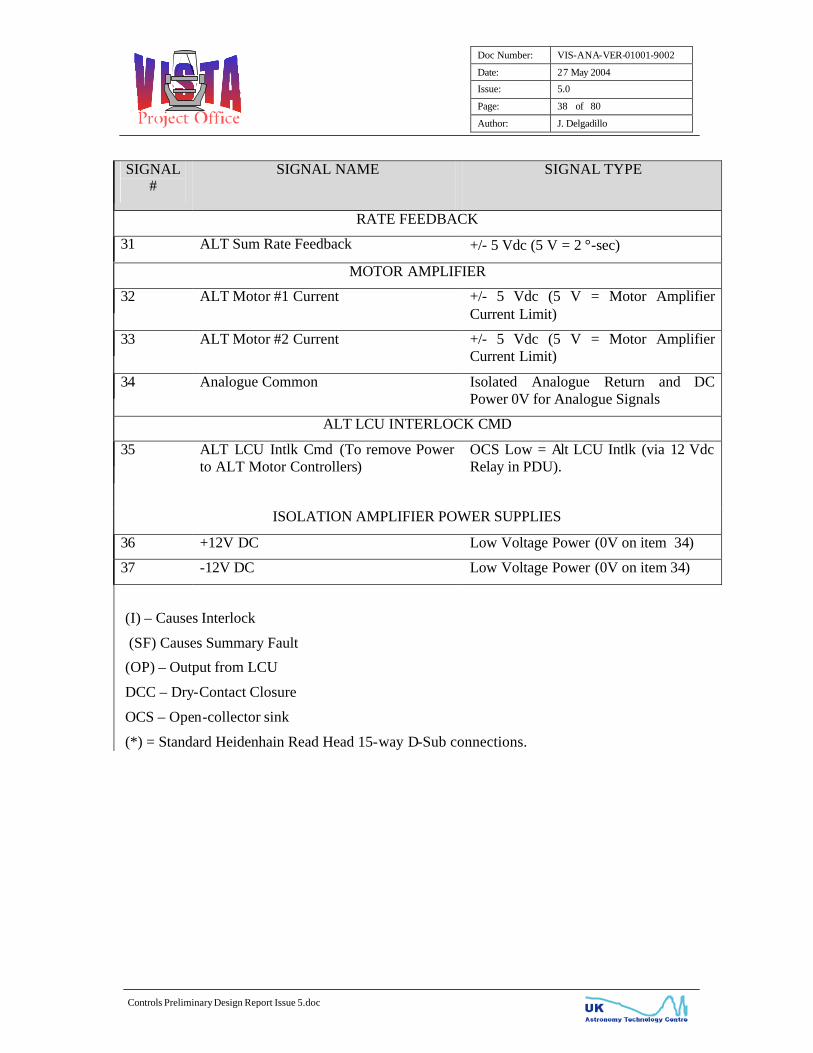
RATE FEEDBACK
31 ALT Sum Rate Feedback +/- 5 Vdc (5 V = 2 °-sec)
MOTOR AMPLIFIER
32 ALT Motor #1 Current +/- 5 Vdc (5 V = Motor Amplifier Current Limit)
33 ALT Motor #2 Current +/- 5 Vdc (5 V = Motor Amplifier Current Limit)
34 Analogue Common Isolated Analogue Return and DC Power 0V for Analogue Signals
ALT LCU INTERLOCK CMD
35 ALT LCU Intlk Cmd (To remove Power to ALT Motor Controllers)
OCS Low = Alt LCU Intlk (via 12 Vdc Relay in PDU).
ISOLATION AMPLIFIER POWER SUPPLIES
36 +12V DC Low Voltage Power (0V on item 34)
37 -12V DC Low Voltage Power (0V on item 34)
(I) – Causes Interlock
(SF) Causes Summary Fault
(OP) – Output from LCU
DCC – Dry-Contact Closure
OCS – Open-collector sink
(*) = Standard Heidenhain Read Head 15-way D-Sub connections.

Doc Number: VIS-ANA-VER-01001-9002
Date: 27 May 2004
Issue: 5.0
Page: 39 of 80
Author: J. Delgadillo
Controls Preliminary Design Report Issue 5.doc
4.2.5 CASS Power Drive Unit
Refer to the following representative photograph (Figure 4.2.2.2.A) and block diagram (Figure 4.2.2.2.B) of the CASS Power Drive Unit. The CASS PDU design is very similar in design to the AZ/ALT PDU. Only the major differences between the two PDUs will be discussed here.
4.2.5.1 CASS PDU Motor Controllers
One of the major differences is the design of the motor controllers. Due to the small capacity needed to drive the Cassegrain rotator, the motor controllers have a built in power supply module and are powered from single-phase utility power. The single-phase utility power will be derived from the VertexRSI 3-phase to 1-phase isolation transformer.
4.2.5.2 CASS Cablewrap
The Cassegrain rotator cable wrap drive will be slaved and Interlocked to the Cassegrain rotator (AD01 10.5.3c, e) as depicted on Figure 4.2.2.2.C. An LVDT will be used to ensure that the cable wrap remains synchronised with the Cassegrain rotator axis. If for any reason a divergence is noted between the Cassegrain rotator axis and the cable wrap, all motor controller power will be removed via the Interlock Chain. Additionally, if the cablewrap motor or motor controller faults out, the Cassegrain rotator axis will be disabled.

Doc Number: VIS-ANA-VER-01001-9002
Date: 27 May 2004
Issue: 5.0
Page: 40 of 80
Author: J. Delgadillo
Controls Preliminary Design Report Issue 5.doc
Figure 4.2.2.2.A - CASS POWER DRIVE UNIT (Photo is Representative)

Doc Number: VIS-ANA-VER-01001-9002
Date: 27 May 2004
Issue: 5.0
Page: 41 of 80
Author: J. Delgadillo
Controls Preliminary Design Report Issue 5.doc
Figure 4.2.2.2.B - CASS PDU BLOCK DIAGRAM

Doc Number: VIS-ANA-VER-01001-9002
Date: 27 May 2004
Issue: 5.0
Page: 42 of 80
Author: J. Delgadillo
Controls Preliminary Design Report Issue 5.doc
Figure 4.2.2.2.C – Cassegrain Rotator Cable Wrap Slaving
4.2.5.3 CASS Interlocking
The interlock chain will consist of the following contacts in series:
Emergency Stops (AZ Motor 1-2, AZ Motor 3-4, Alt Motor 1, Alt Motor 2, Alt Pier, Equipment Room, and Cone E-stops)
Cass Positive/Negative Interlock Limit Cass Stow Pin Engaged Cass/Cass Cable Wrap Divergence Cass LCU Interlock
If any of the above isolated contacts open, power is removed from the Cassegrain (2) and Cassegrain cable-wrap (1) motor controllers and will independently remove the brake release command (AD01 11.1.7 c spec).
Doc Number: VIS-ANA-VER-01001-9002
Date: 27 May 2004
Issue: 5.0
Page: 43 of 80
Author: J. Delgadillo
Controls Preliminary Design Report Issue 5.doc
The same reliability concern by the frequent power cycling of the CASS motor controllers, as discussed in the AZ/ALT PDU section, is applicable to this axis. A second set of the above Interlock contacts is routed over to the CASS LCU for monitoring purposes only. A third set of Interlock contacts is fed to the CASS PDU Control or Status board for fault reporting and axis disabling. This serves as an added safety level of protection, satisfying the operational safety spec of AD01 13.4.11.
4.2.5.4 CASS PMU Control Logic
The Cassegrain PDU also contains the circuitry for the PMU control logic. From the PMU, control of the AZ/ALT or of the CASS axis can be selected. Latching relays in the CASS PDU route either the AZ/ALT or the CASS control/status signals to the appropriate PDU for control of the axis. The PMU can be operated from the AZ/ALT PDU, CASS PDU, or at either PMU Junction box (2).
4.2.5.5 CASS Encoder Interface
As with Azimuth and Altitude axes, the Cassegrain rotator encoder scheme will consist of four read-heads mounted on a Heidenhain ERA 780c optical tape encoder (AD01 11.1.6 g spec). Heidenhain Encoder Splitter boxes are again used to obtain two buffered outputs; one going to the VertexRSI equipment and one going to VISTA’s LCU IK320 Heidenhain Encoder boards.
4.2.5.6 CASS EMC Treatments
The following CASS PDU design features will ensure that the discussed EU EMC standards are met: Properly Shielded Conductive Gasketed Cabinets Completely Connectorized PDU Enclosure EMI/RFI connector backshells Properly terminated Shielded Cables Motor Lead Ferrite Filters 1φ (tech and utility) EMI Filters

Doc Number: VIS-ANA-VER-01001-9002
Date: 27 May 2004
Issue: 5.0
Page: 44 of 80
Author: J. Delgadillo
Controls Preliminary Design Report Issue 5.doc
4.2.5.7 CASS Central Control Unit
Figure 4.2.2.2.D - CASS PDU CCU BLOCK DIAGRAM

Doc Number: VIS-ANA-VER-01001-9002
Date: 27 May 2004
Issue: 5.0
Page: 45 of 80
Author: J. Delgadillo
Controls Preliminary Design Report Issue 5.doc
4.2.5.8 CASS Major Subassemblies
The major subassemblies that make up the CASS PDU are listed below:
TABLE 4.2.2.2.A - CASS PDU Major Subassemblies
MANUFACTURER MANUFACTURER PART NUMBER
DESCRIPTION
Kollmorgen Motion Technologies Group
#CR06250 Cass Motor Controller
Hoffman PROLINE Series CASS PDU Enclosure Heidenhain IBV 606 CASS Encoder Splitter
Box Integrated Power Designs SRW-100-4003 PDU Logic Power
Supply Integrated Power Designs SRW-45-2002 Encoder Power Supply Finder Various Relays Sprecher + Schuh CS4C Series Contactors ABB Control Inc. Various Circuit Breakers Schaffner FN350-12/29 1φ EMI Filter Entrelec Inc. Various Time Delay Relays Shuttle Computer Group G7VP2 CCU Motherboard Delta Tau Turbo PMAC2-PC DSP Card Delta Tau Accessory 51P High Resolution
Interpolator Card Antron SP2-4300FB CCU Power Supply

Doc Number: VIS-ANA-VER-01001-9002
Date: 27 May 2004
Issue: 5.0
Page: 46 of 80
Author: J. Delgadillo
Controls Preliminary Design Report Issue 5.doc
4.2.5.9 CASS LCU Interface
Refer to Figure 4.2.2.1.D, LCU Interface Block Diagram, it shows the handshaking, status, command and feedback information between the CASS PDU and the CASS LCU. As with the AZ/ALT PDU, a manual, mechanical switch in the CASS PDU will be provided to ensure that all LCU Interfaces are identical. Following are the CASS PDU to Cassegrain LCU interfaces.
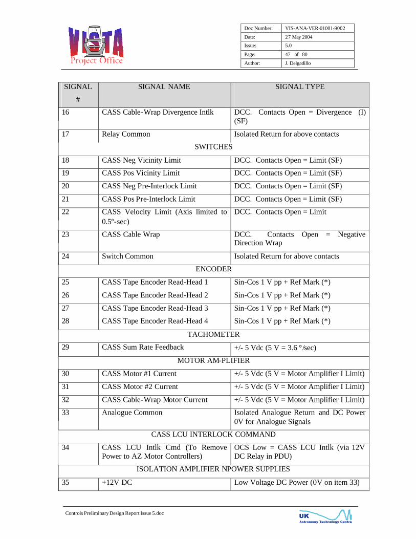
TABLE 4.2.2.2.B - CASS PDU to CASS LCU Interfaces
SIGNAL
#
SIGNAL NAME
SIGNAL TYPE
CONTROL COMMAND-STATUS
1 CASS Rate Demand +/- 5 Vdc, +VE = +VE rate
2 CASS Rate Scale Factor OCS Low = 3.6 deg/s, High = 0.36 deg/s
3 CASS Enable Command OCS Low = Enable
4 +12V Relay +12V DC Relay power (For items 2,3,35)
5 CASS Actual Rate Scale Factor DCC. Contacts Open = 3.6 deg/s, Closed = 0.36 deg/s
6 CASS LCU Available DCC. Contacts Closed = CASS LCU Available
7 CASS LCU Enabled DCC. Contacts Closed = CASS LCU Enabled
8 CASS LCU Active DCC. Contacts Closed = CASS LCU Active
9 CASS Axis Enabled DCC. Contacts Closed = CASS Axis Enabled
10 CASS Summary Fault DCC. Contacts Open = CASS Axis Fault
11 Status Common Isolated Return for above contacts
RELAYS
12 CASS Brakes Released DCC. Contacts Closed = Brakes Released
13 CASS Neg-Pos Interlock Limit DCC. Contacts Open = Limit (I) (SF)
14 CASS CCU Off DCC. Contacts Open = CCU Off
15 CASS Stow Pin Engaged Intlk DCC. Contacts Open = Pin Extended (I) (SF)
Doc Number: VIS-ANA-VER-01001-9002
Date: 27 May 2004
Issue: 5.0
Page: 47 of 80
Author: J. Delgadillo
Controls Preliminary Design Report Issue 5.doc
SIGNAL
#
SIGNAL NAME
SIGNAL TYPE
16 CASS Cable-Wrap Divergence Intlk DCC. Contacts Open = Divergence (I) (SF)
17 Relay Common Isolated Return for above contacts
SWITCHES
18 CASS Neg Vicinity Limit DCC. Contacts Open = Limit (SF)
19 CASS Pos Vicinity Limit DCC. Contacts Open = Limit (SF)
20 CASS Neg Pre-Interlock Limit DCC. Contacts Open = Limit (SF)
21 CASS Pos Pre-Interlock Limit DCC. Contacts Open = Limit (SF)
22 CASS Velocity Limit (Axis limited to 0.5°-sec)
DCC. Contacts Open = Limit
23 CASS Cable Wrap DCC. Contacts Open = Negative Direction Wrap
24 Switch Common Isolated Return for above contacts
ENCODER
25 CASS Tape Encoder Read-Head 1 Sin-Cos 1 V pp + Ref Mark (*)
26 CASS Tape Encoder Read-Head 2 Sin-Cos 1 V pp + Ref Mark (*)
27 CASS Tape Encoder Read-Head 3 Sin-Cos 1 V pp + Ref Mark (*)
28 CASS Tape Encoder Read-Head 4 Sin-Cos 1 V pp + Ref Mark (*)
TACHOMETER
29 CASS Sum Rate Feedback +/- 5 Vdc (5 V = 3.6 °/sec)
MOTOR AM-PLIFIER
30 CASS Motor #1 Current +/- 5 Vdc (5 V = Motor Amplifier I Limit)
31 CASS Motor #2 Current +/- 5 Vdc (5 V = Motor Amplifier I Limit)
32 CASS Cable-Wrap Motor Current +/- 5 Vdc (5 V = Motor Amplifier I Limit)
33 Analogue Common Isolated Analogue Return and DC Power 0V for Analogue Signals
CASS LCU INTERLOCK COMMAND
34 CASS LCU Intlk Cmd (To Remove Power to AZ Motor Controllers)
OCS Low = CASS LCU Intlk (via 12V DC Relay in PDU)
ISOLATION AMPLIFIER NPOWER SUPPLIES
35 +12V DC Low Voltage DC Power (0V on item 33)
Doc Number: VIS-ANA-VER-01001-9002
Date: 27 May 2004
Issue: 5.0
Page: 48 of 80
Author: J. Delgadillo
Controls Preliminary Design Report Issue 5.doc
SIGNAL
#
SIGNAL NAME
SIGNAL TYPE
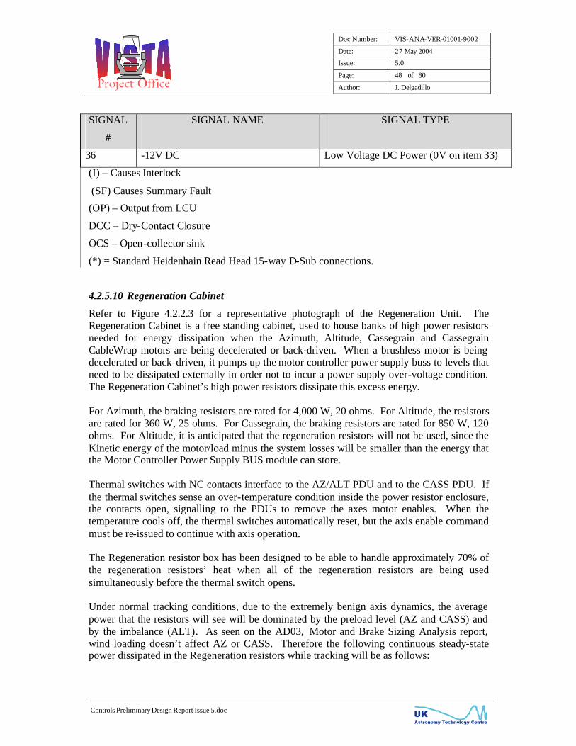
36 -12V DC Low Voltage DC Power (0V on item 33)
(I) – Causes Interlock
(SF) Causes Summary Fault
(OP) – Output from LCU
DCC – Dry-Contact Closure
OCS – Open-collector sink
(*) = Standard Heidenhain Read Head 15-way D-Sub connections.
4.2.5.10 Regeneration Cabinet
Refer to Figure 4.2.2.3 for a representative photograph of the Regeneration Unit. The Regeneration Cabinet is a free standing cabinet, used to house banks of high power resistors needed for energy dissipation when the Azimuth, Altitude, Cassegrain and Cassegrain CableWrap motors are being decelerated or back-driven. When a brushless motor is being decelerated or back-driven, it pumps up the motor controller power supply buss to levels that need to be dissipated externally in order not to incur a power supply over-voltage condition. The Regeneration Cabinet’s high power resistors dissipate this excess energy. For Azimuth, the braking resistors are rated for 4,000 W, 20 ohms. For Altitude, the resistors are rated for 360 W, 25 ohms. For Cassegrain, the braking resistors are rated for 850 W, 120 ohms. For Altitude, it is anticipated that the regeneration resistors will not be used, since the Kinetic energy of the motor/load minus the system losses will be smaller than the energy that the Motor Controller Power Supply BUS module can store. Thermal switches with NC contacts interface to the AZ/ALT PDU and to the CASS PDU. If the thermal switches sense an over-temperature condition inside the power resistor enclosure, the contacts open, signalling to the PDUs to remove the axes motor enables. When the temperature cools off, the thermal switches automatically reset, but the axis enable command must be re-issued to continue with axis operation. The Regeneration resistor box has been designed to be able to handle approximately 70% of the regeneration resistors’ heat when all of the regeneration resistors are being used simultaneously before the thermal switch opens. Under normal tracking conditions, due to the extremely benign axis dynamics, the average power that the resistors will see will be dominated by the preload level (AZ and CASS) and by the imbalance (ALT). As seen on the AD03, Motor and Brake Sizing Analysis report, wind loading doesn’t affect AZ or CASS. Therefore the following continuous steady-state power dissipated in the Regeneration resistors while tracking will be as follows:

Doc Number: VIS-ANA-VER-01001-9002
Date: 27 May 2004
Issue: 5.0
Page: 49 of 80
Author: J. Delgadillo
Controls Preliminary Design Report Issue 5.doc
AZ 594 W CASS 71 W The above tracking dissipation values are well below the continuous rating (15% of AZ, 8% for CASS) of the regeneration resistors and thus will hardly produce minimal heat emissions, if any. The instance where the most heat will be dissipated will be when the telescope is slewing from target to target. Per AD01, Technical Specification, the worse case scenario would be 45° slews on sky, with a 10-minute frequency. Therefore the acceleration/deceleration durations would be 2 seconds for AZ and ALT and 1.4 sec for CASS and the slew durations would be approximately 23 seconds for ALT, 66 seconds for AZ and 36 seconds for CASS. Therefore the duty cycles between changing targets would be approximately 4.5% for ALT, 12% for AZ and 6.5% for CASS. The low duty cycles result in negligible average power dissipated in the resistors, thus the above-mentioned dissipated tracking power is still valid when slewing from target to target. The transient (peak) power seen by the resistors is the most when the motors are commanded to decelerate (since for accelerations, the AZ, CASS back-driven motors’ regeneration levels would drop due to the high current command needed to accelerate). Therefore the transient power that the resistors would see would be: AZ 8.6A = 1,479 W (37% of rated) CASS 1.09 A = 142 W (17% of rated) The above values are still way below the rated values, and well below the thermal switch trip threshold. Therefore, conditions much more severe (having higher duty cycle) than those listed for this application would be needed in order to have an over temperature condition.
4.2.5.11 Isolation Transformer
The Isolation Transformer houses a 3-φ to 1-φ 5 KVA and a 3-Phase 50 KVA electro statically shielded transformers. The transformers secondary feed the AZ/ALT and the CASS PDU cabinets. This power is used to drive the brushless DC motors and the Azimuth bearing lube pump and other utility powered equipment.

Doc Number: VIS-ANA-VER-01001-9002
Date: 27 May 2004
Issue: 5.0
Page: 50 of 80
Author: J. Delgadillo
Controls Preliminary Design Report Issue 5.doc
Figure 4.2.2.3 - REGENERATION CABINET (Photo is Representative)

Doc Number: VIS-ANA-VER-01001-9002
Date: 27 May 2004
Issue: 5.0
Page: 51 of 80
Author: J. Delgadillo
Controls Preliminary Design Report Issue 5.doc
4.2.5.12 Data Acquisition System
The Data Acquisition System is comprised of the Data Acquisition Unit, 25 VertexRSI provided RTDs (AD01 6.4.5a spec) and conditioning modules for VISTA provided 15 additional temperature sensors (AD01 6.4.5c & d spec). 5 of these sensors will be located on the structure while the remaining 10 will be placed on the M1 mirror. It is assumed that the same type of conditioning modules will be used for the VISTA provided sensors as the ones used for the VertexRSI provided temperature sensors (100 ohm RTDs). The Data Acquisition Unit will reside inside the mount Yoke and will interface via the CANOpen protocol to the M1 Mirror Support LCU. The RTDs to be provided by VertexRSI are a 3-wire platinum RTD manufactured by Pyromation, Inc having part number R3T1853RB1-F3B006-6. The 100 ohm platinum RTD (AD01 6.4.3 spec) has a temperature coefficient of 0.00385 and an accuracy of +/- 0.03% @ 0°C. For the operational temperature range of 0 to 15 °C, the corresponding accuracy of the RTD would be 0.08 to 0.10 °C. The location of the 25 VertexRSI Provided RTDs will be as follows: OSS Spyder 4 OSS Ring 2 OSS Tube 6 ALT Ring 4 ALT Bearing 2 Mirror Strt 3 Outside Pier 2 Inside Pier 2 As requested by VPO, VRSI is planning on using Beckhoff CANOpen hardware for the Data Acquisition Unit. The Beckhoff RTD modules have a published measurement accuracy of +/-1 °C over the entire measurement range of – 250 °C to 850 °C. The RTDs to be provided have a temperature range of –200 to +200 °C, thus the Beckhoff measurement error would be reduced to approximately +/- 0.4 °C. Conversation with Beckhoff seems to indicate that the published 1 °C accuracy number is too conservative and that typical values are in the order of 0.5 °C, thus, for our temperature range, the measurement error would be approximately +/- 0.2 °C. This accuracy would be for the un-calibrated measurement, thus calibration of the measurement would yield accuracy values closer to the AD01 6.4.3 0.1°C accuracy spec. Since the Mount Control System is not required to obtain the temperature information, the M1 Mirror Support LCU would be responsible for the calibration of the RTDs. Vista has exercised the M1 mirror LVDT option, thus six of the M1 mirror sensors will become the AC LVDTs. The last four sensors would remain the RTDs. AC LVDTs were

Doc Number: VIS-ANA-VER-01001-9002
Date: 27 May 2004
Issue: 5.0
Page: 52 of 80
Author: J. Delgadillo
Controls Preliminary Design Report Issue 5.doc
selected over their DC counterparts for their superior accuracy. The accuracy of the LVDTs is comparable to that of the M1 load cells. AD11 shows the interfaces between the M1 Mirror Support LCU and the Data Acquisition Unit, as well as the interfaces to the M1 Mirror Support electronics and anemometer interfaces
Figure 4.2.2.6 - DATA ACQUISITION UNIT (Photos are Representative)

Doc Number: VIS-ANA-VER-01001-9002
Date: 27 May 2004
Issue: 5.0
Page: 53 of 80
Author: J. Delgadillo
Controls Preliminary Design Report Issue 5.doc
The major subassemblies that make up the Data Acquisition System are listed below:
MANUFACTURER MANUFACTURER PART NUMBER
DESCRIPTION
CONDOR D.C. POWER SUPPLIES, INC
HC24-2.4A+ Power Supply
Beckhoff BK5120 CANOpen Bus Coupler Beckhoff KL3102 2 Channel Analogue
Input Terminal Beckhoff KL3202 2 Channel Input Terminal
PT100 (RTD) Pyromation Incorporated R3T1853 Series 3-Wire, Platinum RTD
4.2.5.13 Optical Incremental Tape Encoder
The position encoders to be used are the Heidenhain ERA 880C, distance-coded tape encoder, for the Azimuth, Altitude and Cassegrain Rotator axes. The optical encoders contain gold line graduations, which reflect light in a defined direction, and diffusely reflecting gaps. These Heidenhain tape encoders operate on the principle of photo-electrically scanning very fine gratings. The photoelectric scanning of a substrate is the measurement of the change in light intensities using photovoltaic cells. When a line grating is moved relative to another grating with the same structure, the lines of two graduations alternately align. The resulting light-dark modulation is sensed by photovoltaic cells. Electronics in the tape encoder read-heads produces two sinusoidal waveforms that are shifted from each other by 90°, and have approximate amplitude of 1 V peak-to-peak as the scanning reticule is moved across the fixed scale tape. The ERA 880C incremental encoders have a steel scale tape with a grating period of 40 microns. The tape encoders have a second (reference) track that consists of graduated disks next to the incremental grating. This reference track is distance-coded, which means that the number of graduations between reference marks is unique. An algorithm is then implemented to obtain an absolution axis position after traversing two consecutive reference marks.

Doc Number: VIS-ANA-VER-01001-9002
Date: 27 May 2004
Issue: 5.0
Page: 54 of 80
Author: J. Delgadillo
Controls Preliminary Design Report Issue 5.doc
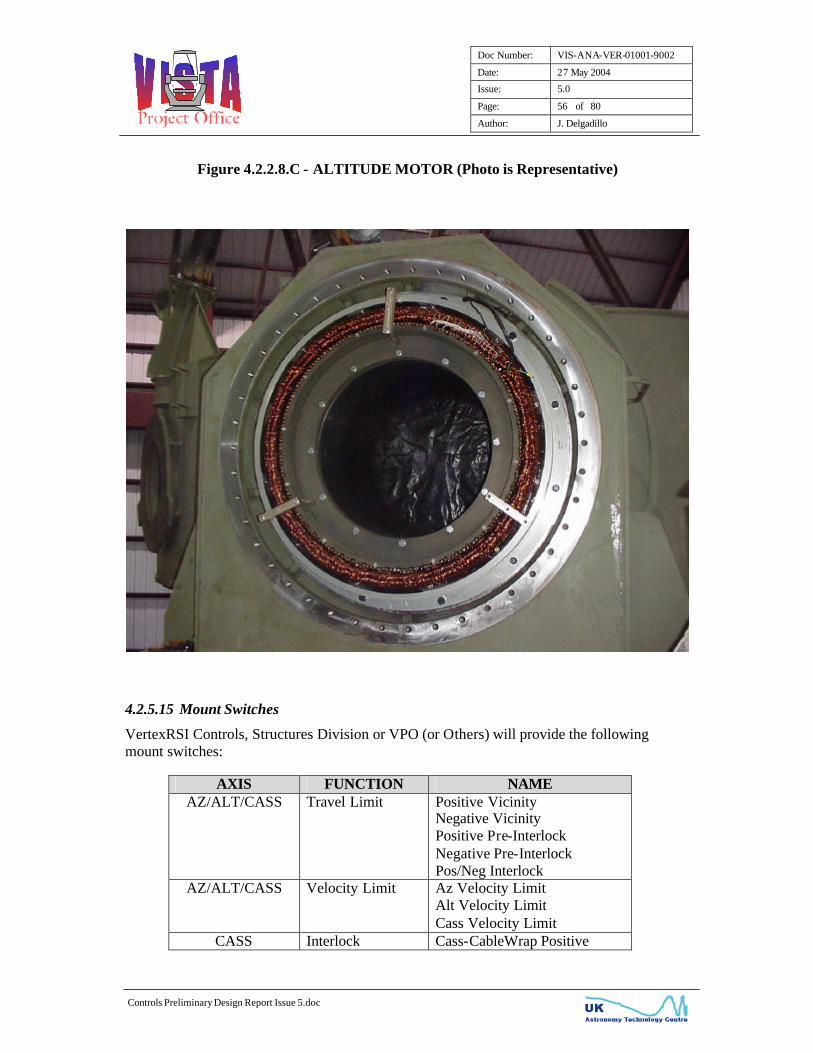
4.2.5.14 AZ, ALT and CASS Drive Motors and Brakes
Brushless Motors were selected for the mount’s axes movement. For Azimuth, four (4) 5,000 RPM, 10 HP motors were selected. For Altitude, two (2) 0.17 HP, 1/3 RPM frameless torquer motors were selected. For Cassegrain three (3) 1.3 HP, 3800 RPM brushless motors were selected. Refer to Figure 4.2.2.8.A, B & C for representative photographs of the axis motors. The brushless digital motor controllers obtain shaft position information from an integral encoder to accomplish commutation of the motors. For Azimuth and Cassegrain Rotator, the position information comes from an absolute resolver. For Altitude the position information comes from Hall Sensors and from a Heidenhain Interpolation box (per motor) that digitises the optical tape encoder sinusoidal signals. The amplifiers commutate the DC voltage to create a rotating magnetic field. The Azimuth and Cassegrain axes motors have DC tachometers installed to provide velocity feedback information for the Rate Loop boards to close the velocity loop. For the Altitude motors, the optical tape encoders are used by electronics in the AZ/ALT PDU CCU to produce an analogue voltage representative of the altitude motor’s speed. Each motor has an integral thermostat contact that opens if the motor overheats. When this occurs, the motor controller enable is removed, while the other motor(s) in the axis continue to remain operational. The status of this switch is reported to and displayed at the MCU and to the appropriate LCU. The thermostat contact automatically reset once the windings of the motor have cooled off. These motors have military circular connectors that allow ease of replacement (with the obvious exception of the Altitude motors). The AZ and Cassegrain motors employ sealed bearings that do not require greasing. The motors are rated with an IP67 sealing specification. VertexRSI will be using pneumatic brakes for all the axes. The fundamental concept of brakes supplied by VertexRSI is that they are spring actuated, failsafe brakes. That is, the brakes will only release the mount for movement when voltage is applied to the brake control valve. Alternatively, loss of power will apply the brakes. Pressure sensors are used to indicate to the Mount Control System when the brake has the necessary compressed air to disengage the brake. If the pressure sensor fails to indicate this condition, a brake fault is issue to the appropriate PDU and the axis enable command is removed. The brake fault condition is reported to the MCU, LCU and to the PMU 2-line LCD display.

Doc Number: VIS-ANA-VER-01001-9002
Date: 27 May 2004
Issue: 5.0
Page: 55 of 80
Author: J. Delgadillo
Controls Preliminary Design Report Issue 5.doc
Figure 4.2.2.8.A - AZIMUTH MOTOR (Photo is Representative)
Figure 4.2.2.8.B - CASSEGRAIN MOTOR (Photo is Representative)
Doc Number: VIS-ANA-VER-01001-9002
Date: 27 May 2004
Issue: 5.0
Page: 56 of 80
Author: J. Delgadillo
Controls Preliminary Design Report Issue 5.doc
Figure 4.2.2.8.C - ALTITUDE MOTOR (Photo is Representative)
4.2.5.15 Mount Switches
VertexRSI Controls, Structures Division or VPO (or Others) will provide the following mount switches:
AXIS FUNCTION NAME AZ/ALT/CASS Travel Limit Positive Vicinity
Negative Vicinity Positive Pre-Interlock Negative Pre-Interlock Pos/Neg Interlock
AZ/ALT/CASS Velocity Limit Az Velocity Limit Alt Velocity Limit Cass Velocity Limit
CASS Interlock Cass-CableWrap Positive

Doc Number: VIS-ANA-VER-01001-9002
Date: 27 May 2004
Issue: 5.0
Page: 57 of 80
Author: J. Delgadillo
Controls Preliminary Design Report Issue 5.doc
AXIS FUNCTION NAME Divergence Lim Cass-CableWrap Negative Divergence Lim
AZ/CASS CableWrap Sector Azimuth CableWrap Cass CableWrap
AZ/ALT/CASS Stow Pin Stowed Stow Pin Engaged (AD01 11.1.9 spec)
AZ Lube Pump Pressure Low Overflow (AD01 9.2.1 g spec)
ALT Imbalance M2 Unit Not Installed CASS Instrument Not Installed OSS Not Installed ALT Imbalance Pin Cradle ALT Manual Brake Release
AZ/ALT Mount Parked AZ Mount Parked ALT Mount Parked (AD01 13.4.12 spec)
ALT Aux Drive Intlk ALT Aux Drive On Intlk AZ/ALT/CASS Emergency Stop AZ Motor 1-2 E-stop
AZ Motor 3-4 E-stop ALT Motor 1 E-stop ALT Motor 2 E-stop ALT Pier E-stop Equipment Room E-stop Cone E-stop
AZ AZ Interlock Yoke Access Hatch Intlk #1 Yoke Access Hatch Intlk #2 Pier Access Interlock Mobile Access Platform Intlk
ALT ALT Interlock M1 Restraint Failure Mobile Access Platform Intlk AZ Floor Access Interlock
There will be three (3) levels of over-travel protection in hardware for each axis. The levels of protection are: Pos/Neg Vicinity Limit, Pos/Neg Pre-Interlock Limit and Pos/Neg Interlock (lanyard/buffer) Limit. Upon the activation of the Limits, the following will occur: Vicinity Limit: Fault is reported to the MCU and LCU-fed contacts open. Axis motors remain active and axis automatically backs-out of the limit condition.

Doc Number: VIS-ANA-VER-01001-9002
Date: 27 May 2004
Issue: 5.0
Page: 58 of 80
Author: J. Delgadillo
Controls Preliminary Design Report Issue 5.doc
Pre-Interlock Limit - Fault is reported to the MCU and LCU-fed contacts open. Axis motors are disabled. The Limit Override momentary switch (inside the appropriate Power Drive Unit) needs to be continuously depressed until the limit clears. Interlock Limit - Fault is reported to the MCU and LCU-fed contacts open. Interlock chain is broken which causes removal of utility power (3-phase power (AZ/ALT) or 1-phase power (CASS)) to the axis motor controllers. Recovery of the Interlock Limit can only be done by manually (physically) moving the structure and clearing the Interlock Limit. AD01 11.1.8.2 states "In maintenance mode it shall be possible to drive all axes to the Interlock limits under local engineering control at a reduced slew rate to verify the correct functioning of the Interlock system". VertexRSI will not comply with this requirement as it could result in a potential safety hazard. The control system hardware will not allow driving past the Pre-Vicinity Limits. Of course during the commissioning/testing of the system, temporary bypassing of travel limits are allowed/necessary in order for the activation of the 2nd and 3rd level of travel limit protection.
4.2.5.16 Anemometers
Three anemometers will be provided which will interface directly with the M1 Mirror Support LCU. As recommended, the anemometers are manufactured by GILL Instruments Ltd (AD01 6.4.4 spec). The manufacturer part number is 1086-PK-046. The recommended units don’t come with RS485 interface, but will be provided with their standard RS-422 serial interface. The power requirement for the anemometers will come directly from the LCU, shown on Table 4.2.5.16, and is as follows: 9 to 30 Vdc, 120mA max.
TABLE 4.2.5.16 - M1 Mirror Support LCU Interfaces SIGNAL
# SIGNAL NAME SIGNAL TYPE
ANEMOMETER (AD06 3.3 spec) 1 Anemometer #1 RS-422 + Power 2 Anemometer #2 RS-422 + Power 3 Anemometer #3 RS-422 + Power

Doc Number: VIS-ANA-VER-01001-9002
Date: 27 May 2004
Issue: 5.0
Page: 59 of 80
Author: J. Delgadillo
Controls Preliminary Design Report Issue 5.doc
4.2.6 Material Parts
All fastening hardware utilized on the Mount Control Systems sub-assemblies will be metric. As agreed, modification of off-the-shelf assemblies or line-replaceable unit subcomponents to metric hardware will not be done. However, most sub-assemblies are already provided as metric units such as the Motor Controller Power Supplies, Motor Controllers, Encoder Interpolator and Splitter boxes, among others. For the sub-assembly hardware that will not be metric, it will be at least serviceable with a Phillips or flat blade screwdriver. As previously discussed, chassis, covers, rear-panels, front panels, etc. used for the Mount Control System sub-assemblies, will not be made of metric steel.
4.2.7 Documentation
VertexRSI drawing number 93-100-2877 (VPO dwg no. VIS-DWG-VER-01001-9000), VISTA MCS Top Level Drawing, shows the list of deliverables for the mount control system. The parts list of this document shows the part numbers (VertexRSI as well as VPO part numbers) for the sub-assemblies that comprise the mount control system. This top level drawing also shows the configuration of the MCU and CCU Interface boards, the Status Board and the Control Board. The configuration is the component and circuit changes made to the baseline boards. In this manner, VertexRSI can build ahead baseline boards and then the board can be configured, per the Top Level drawing, to meet the program’s specific requirements. An Indentured Drawing List drawing, 99-343-0009, (VPO drawing no. VIS-DWG-VER-01001-9009) shows the list of deliverable drawings. A section of the O&M Manual gives a cross-reference between the VertexRSI and the VPO drawings.
4.2.8 Break-out Boxes
Seven break-out boxes will be provided per the requirements of AD07. The break-out boxes are not provided for all connectors. If connection between Unit A and Unit B has different types of connectors, a break-out box is only provided to connect to Box A, since there’s no need to provide a break-out box for Box B. For obvious safety reasons, break-out boxes are not provided for power (AC) or high voltage (AC or DC) connectors since the AD07 spec for the break-out boxes is implicitly for control signals. Additionally, two-wire circuits are not supplied with break-out boxes, as debug is simple, thus not requiring a break-out box.

Doc Number: VIS-ANA-VER-01001-9002
Date: 27 May 2004
Issue: 5.0
Page: 60 of 80
Author: J. Delgadillo
Controls Preliminary Design Report Issue 5.doc
4.3 Tape Encoder Calculations
4.3.1 Azimuth Tape Encoder Calculations
Azimuth Tape Encoder Resolution
Tape Sitting Diameter: 1638mm Tape Sitting Circumference: 1638mm * Π = 5,145.9288 mm Graduation Distance 40 e-6 mm = 25 lines/mm # of Encoder Lines 25 lines/mm * 5,145.9288mm = 128,648.2192 lines IK 320 Interpolation Factor 4096 counts/line * 128,648.2192 lines = 526,943,105.8 counts Encoder Resolution 360°/526,943,105.8 counts = 6.832 e-7 deg = 0.0025 arc-secs
Azimuth Tape Encoder Accuracy
Encoder Accuracy of Graduation +/- 3 microns = +/- 0.003 mm Encoder Tape Circumference 5,145.9288mm = 360° = 0.070 °/mm Encoder Accuracy (One Read-Head) 0.07 °/mm * 0.003 mm = 0.00021 ° = 0.755 arc-sec peak Encoder Accuracy (4 Read-Heads) = 0.755 arc-sec / 2 = 0.378 arc-sec peak
4.3.2 Altitude Tape Encoder Calculations
Altitude Tape Encoder Resolution
Tape Sitting Diameter: 1854mm Tape Sitting Circumference: 1854mm * Π = 5,824.5128 mm Graduation Distance 40 e-6 mm = 25 lines/mm # of Encoder Lines 25 lines/mm * 5,824.5128mm = 145,612.8195 lines IK 320 Interpolation Factor 4096 counts/line * 145,612.8195 lines = 596,430,108.7 counts Encoder Resolution 360°/596,430,108.7 counts = 6.0359 e-7 deg = 0.0022 arc-secs
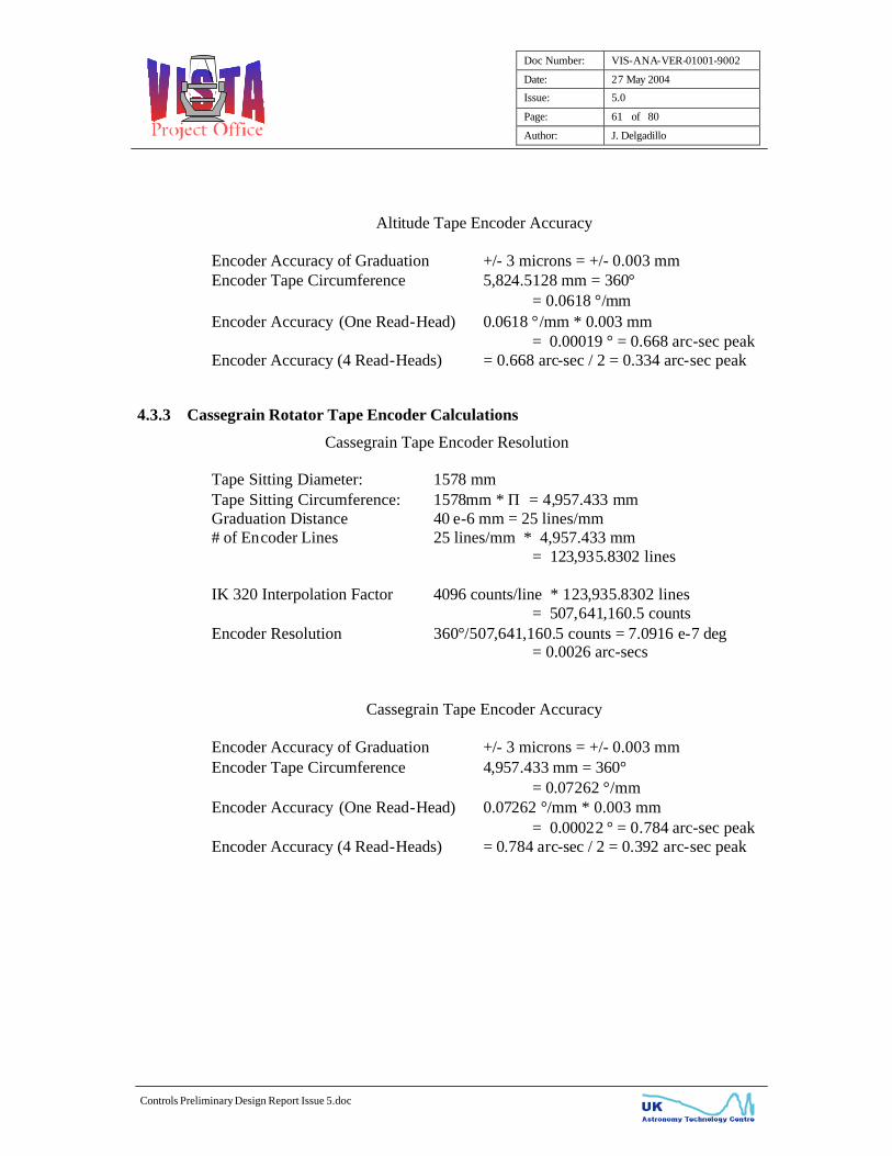
Doc Number: VIS-ANA-VER-01001-9002
Date: 27 May 2004
Issue: 5.0
Page: 61 of 80
Author: J. Delgadillo
Controls Preliminary Design Report Issue 5.doc
Altitude Tape Encoder Accuracy
Encoder Accuracy of Graduation +/- 3 microns = +/- 0.003 mm Encoder Tape Circumference 5,824.5128 mm = 360° = 0.0618 °/mm Encoder Accuracy (One Read-Head) 0.0618 °/mm * 0.003 mm = 0.00019 ° = 0.668 arc-sec peak Encoder Accuracy (4 Read-Heads) = 0.668 arc-sec / 2 = 0.334 arc-sec peak
4.3.3 Cassegrain Rotator Tape Encoder Calculations
Cassegrain Tape Encoder Resolution
Tape Sitting Diameter: 1578 mm Tape Sitting Circumference: 1578mm * Π = 4,957.433 mm Graduation Distance 40 e-6 mm = 25 lines/mm # of Encoder Lines 25 lines/mm * 4,957.433 mm = 123,935.8302 lines IK 320 Interpolation Factor 4096 counts/line * 123,935.8302 lines = 507,641,160.5 counts Encoder Resolution 360°/507,641,160.5 counts = 7.0916 e-7 deg = 0.0026 arc-secs
Cassegrain Tape Encoder Accuracy
Encoder Accuracy of Graduation +/- 3 microns = +/- 0.003 mm Encoder Tape Circumference 4,957.433 mm = 360° = 0.07262 °/mm Encoder Accuracy (One Read-Head) 0.07262 °/mm * 0.003 mm = 0.00022 ° = 0.784 arc-sec peak Encoder Accuracy (4 Read-Heads) = 0.784 arc-sec / 2 = 0.392 arc-sec peak

Doc Number: VIS-ANA-VER-01001-9002
Date: 27 May 2004
Issue: 5.0
Page: 62 of 80
Author: J. Delgadillo
Controls Preliminary Design Report Issue 5.doc
4.4 Conclusions This Design Report, along with the referenced analysis reports, has shown how the design of the VISTA Mount Control System is in compliance to AD01 Technical Specification. Non-compliant or partially compliant specifications are also addressed in this and on the referenced reports.
__oOo__

Doc Number: VIS-ANA-VER-01001-9002
Date: 27 May 2004
Issue: 5.0
Page: 63 of 80
Author: J. Delgadillo
Controls Preliminary Design Report Issue 5.doc
Appendix A
Mount Control Unit

Doc Number: VIS-ANA-VER-01001-9002
Date: 27 May 2004
Issue: 5.0
Page: 64 of 80
Author: J. Delgadillo
Controls Preliminary Design Report Issue 5.doc
Appendix A - Mount Control Unit
The MCU will be used to show compliance to the pointing and tracking requirements of the mount, per AD01 11.1.3 spec. Following is a brief description of the MCU hardware and its modes of operation. Refer to the following representative photograph and block diagram of the Mount Control Unit. The MCU power supply is a 250W switching power supply with universal input. It supplies logic power (+5, +/- 15 Vdc) to the off-the-shelf motherboard and to the floppy and hard drive of the MCU. The Motherboard is an off-the-shelf Pentium processor. System software is done on a real-time operating system (QNX) in C language. The motherboard has a built in IDE control function, which controls the Floppy Drive and the Hard Drive. The Floppy Drive is a standard 3.5” drive that is used for backing-up system parameters. The Hard Drive is a 16 Meg, solid-state, flash disc drive where the system software program and database resides. The local display is a 250mm colour LCD that uses TFT technology. The speaker sounds an audible alarm whenever there are new faults present. Additionally, contact closure status is available for summary and unacknowledged faults. The MCU Interface board provides the interface between the MCU and the rest of the control system equipment. It provides the serial link to the AZ/ALT PDU and to the CASS PDU. This link is used for gathering of system faults & issuing of position commands to the PDUs Central Control Units. As mentioned earlier, the MCU will be used to show compliance to the pointing and tracking requirements. The MCU Open Position Loop Bode plot is the position filtering that the MCU implements. The break frequencies are done digitally, through parameters in the MCU. The LAG1 break frequency determines whether the position loop is a Type I or Type II. For this demanding application a Type II position loop is warranted, therefore, the LAG1 break frequency is disabled (taken to 0 Hz).

Doc Number: VIS-ANA-VER-01001-9002
Date: 27 May 2004
Issue: 5.0
Page: 65 of 80
Author: J. Delgadillo
Controls Preliminary Design Report Issue 5.doc
Below are the initial break frequencies that we will start-off with the integrated testing at Mexia, Texas. AZ ALT LAG 1 0.0 Hz 0.0 Hz Lead 0.24 Hz 0.192 Hz Crossover 1.00 Hz 0.80 Hz Lag 2 10.00 Hz 10.00 Hz The single PI architecture that the LCU’s Position Loop will implement is compatible with the MCU position loop architecture, with the exception of the absence of the LAG2 break shown on the Bode plot. VertexRSI will implement an active (hardware) low pass filter that will be added to the LCU rate command output so that the LCU position loop will be completely compatible with the MCU’s. During the Integrated testing at Mexia, Texas, the optimal position loop compensation needed will be determined. VertexRSI will do a mapping of the optimal MCU position loop parameters to the ESO PI compensation loop parameters. In this manner, during the VPO testing period, the LCU can test the mount performance using the same Position Loop filtering that the MCU used for initial sell-off the Mount Control System. The major subassemblies that make up the MCU are listed below:
MANUFACTURER MANUFACTURER PART NUMBER
DESCRIPTION
Antron SP2-4300FB MCU Power Supply Shuttle Computer Group G7VP2 MCU Motherboard NEC Electronics NL6448AC33-29 LCD Display Touchstone Technology ASM5051 LCD Controller Board Chinon America Inc. FZ-357 Floppy Drive M-Systems Inc. IDE-FD25-32 Hard Drive
Following are some of the MCU Modes of Operation and a brief description of each.

Doc Number: VIS-ANA-VER-01001-9002
Date: 27 May 2004
Issue: 5.0
Page: 66 of 80
Author: J. Delgadillo
Controls Preliminary Design Report Issue 5.doc
MOUNT CONTROL UNIT (Photo is Representative)
MCU BLOCK DIAGRAM

Doc Number: VIS-ANA-VER-01001-9002
Date: 27 May 2004
Issue: 5.0
Page: 67 of 80
Author: J. Delgadillo
Controls Preliminary Design Report Issue 5.doc
1. Position Track (Designate) Mode
Position Track accepts dynamic time tagged AZ/ALT/CASS position and velocity commands at a 20 Hz rate with three commands ahead in time. Interpolation smoothes the data to achieve excellent trajectory. Position Track can be used for both dynamic trajectories and point-to-point moves. The MCU 100BaseT Ethernet interface is provided for the Host Computer to command the Position Track mode.
2. Star Track Mode The Star Track Mode continuously positions the mount on an internally calculated trajectory of a celestial object. The MCU allows the entry, storage and modification of trajectory elements for up to ten separate celestial targets. Other targets can be tracked by simply entering the target’s Right Ascension and Declination parameters. Position and time offsets may be entered from the MCU for “fine-tuning” the trajectory predictions.
MCU Open Position Loop Bode Plot

Doc Number: VIS-ANA-VER-01001-9002
Date: 27 May 2004
Issue: 5.0
Page: 68 of 80
Author: J. Delgadillo
Controls Preliminary Design Report Issue 5.doc
3. Manual Position (Offset) Mode The Manual Position (Offset) mode can be superimposed on trajectory pointing or positioning mode. It allows the operator to manually command position offsets to the position loop mode operating in conjunction. This allows the trajectory pointing mode or positioning mode to be fine-tuned.
4. Preset Position Mode The Preset Position Mode contains 40 selectable AZ/ALT/CASS positions. Execution of the Preset Position Mode relocates the mount to a position defined by the stored positions.
5. Signal Meters The MCU can display eight signals simultaneously in a bar graph format. Each signal has a minimum and maximum range selection. The first three signals selected are output to the AZ/ALT PDU Analogue Test Points located on the PMU bracket, the 4th – 6th signals selected are output to the CASS PDU Analogue Test Points located on the PMU bracket. The analogue voltages are limited to +/- 5Vdc. Additionally, the CCU Interface board provides the above mentioned 3 analogue test points from the AZ/ALT PDU and 3 analogue test points from the CASS PDU to the Data Acquisition Unit. The Data Acquisition Unit digitises these signals and the signals then become available over the CANOpen interface. These signals can be used for troubleshooting purposes. The list of available signals is: AZ, ALT, CASS Position Command AZ, ALT, CASS Position Error AZ, ALT, CASS Position Feedback AZ, ALT, CASS Rate Command AZ, ALT, CASS Encoder Velocity AZ, ALT, CASS Sum Rate AZ, ALT, CASS Current Command AZ Motor 1, 2, 3, 4 Rates ALT Motor 1, 2 Rates CASS Motor 1, 2 Rates CASS Cable Wrap Motor Rate AZ Motor 1, 2, 3, 4 Current ALT Motor 1, 2 Current CASS Motor 1, 2 Current CASS Cable Wrap Motor Current AZ/ALT CCU + 15 V AZ/ALT CCU – 15V AZ/ALT CCU + 5 V AZ/ALT +24 V AZ/ALT Temperature (CCU)

Doc Number: VIS-ANA-VER-01001-9002
Date: 27 May 2004
Issue: 5.0
Page: 69 of 80
Author: J. Delgadillo
Controls Preliminary Design Report Issue 5.doc
CAS CCU + 15 V CASS CCU – 15V CASS CCU + 5 V CASS +24 V CASS Temperature (CCU) AZ Read-Head 1, 2, 3, 4 Positions ALT Read-Head 1, 2 Tape 1 Position ALT Read-Head 1, 2 Tape 2 Positions CASS Read-Head 1, 2, 3, 4 Positions AZ Read-Head 1, 2, 3, 4 Position Errors ALT Read-Head 1, 2 Tape 1 Position Error ALT Read-Head 1, 2 Tape 2 Position Errors CASS Read-Head 1, 2, 3, 4 Position Errors
6. AZ Jitter Image Stabilizer The Azimuth Jitter Image Stabilizer compensates for Azimuth induced rotary jitter by feeding the Azimuth error signal into the active Cassegrain axis to counter rotate the image.
7. Cassegrain Slave Mode The Cassegrain can be commanded to the Slave Mode whereas the Cassegrain Axis motion is generated based on the Azimuth and Altitude trajectories.
8. Stow Mode Stow Mode’s purpose is to drive the mount to a safe location and then lock the mount there with the stow pins. Upon entry into the Stow Mode, position commands are issued to drive the AZ/ALT/CASS axes to the predetermined location. The stow sequence is to drive to the designated position and once the location is reached, the axes enables are removed and the brakes are set.
9. Stop Mode This mode disables the Azimuth, Altitude and Cassegrain axis drives. It is often referred to as Standby. “Disabling” signifies that the motor controller enables have been removed, it doesn’t signify that the motor controller utility (3-φ) power has been removed.
10. Axis Disable The Axis Disable is similar to Stop Mode with the exception that it allows single axis disable of the axis drives. This allows the operator the ability to eliminate motion on axes not of interest and focus on one axis for test or maintenance purposes.
Doc Number: VIS-ANA-VER-01001-9002
Date: 27 May 2004
Issue: 5.0
Page: 70 of 80
Author: J. Delgadillo
Controls Preliminary Design Report Issue 5.doc
11. Test Trajectories Pre-mission test functions are onboard to support full axis known motion conditions. This allows fully expected performance to be reconfirmed during maintenance of critical mission event preparation. The following test functions are supported:
• t2 ; Constant acceleration and deceleration to measure the system’s static Acceleration Error Coefficient (Ka) per axis
• Flyby; Low target flyby of mount location to measure the system’s dynamic Ka
• Constant Velocity; Measure running friction and position error.
12. Maintenance Mode When the MCU is put in Maintenance Mode, control is transferred to the Portable Maintenance Unit (PMU). Once the PMU has accepted control, the MCU (and the LCUs) cannot take control back until the PMU relinquishes control.
13. LCU Mode Upon power-up, the MCU will default to LCU mode. When in LCU mode, the AZ, ALT and CASS LCUs will be able to take control of the system via the manual, mechanical PDU switch. As with the Maintenance Mode, once the LCUs are in control of the system, the MCU and the PMU are unable to take control until the LCUs relinquishes control of the mount. LCUs Relinquishing control of the mount is made via the PDU switch. If the MCU is in control of the mount and looses communication to the Power Drive Units, control is automatically offered to both the PMU and to the LCUs. Whichever unit takes control first will control the mount. Whenever the unit that has control of the mount looses communication to the appropriate PDU, the MCS reverts to “STOP” mode, whereas all motor controller enables are taken away. For the LCUs, loosing communication signifies that the PDU manual switch has been switched from the “LCU” to the “PMU/MCU” position or the UPS power has cycled.

Doc Number: VIS-ANA-VER-01001-9002
Date: 27 May 2004
Issue: 5.0
Page: 71 of 80
Author: J. Delgadillo
Controls Preliminary Design Report Issue 5.doc
Appendix B
Portable Maintenance Unit
Doc Number: VIS-ANA-VER-01001-9002
Date: 27 May 2004
Issue: 5.0
Page: 72 of 80
Author: J. Delgadillo
Controls Preliminary Design Report Issue 5.doc
Appendix B - Portable Maintenance Unit
The Portable Maintenance Unit (PMU) is a microprocessor independent unit with the controls and status indicators to execute manual rate control for Azimuth, Altitude and Cassegrain Rotator axis. Refer to the following representative photograph of the PMU and of the PMU junction box. The PMU has a 15 meter connectorized pendant cable that may be interfaced at the AZ/ALT Power Drive Unit, the CASS Power Drive Unit or at junction box #1 or #2. The PMU can be plugged at any of the above-indicated ports at any time, regardless of which unit has control of the MCS. The PMU is capable of performing these operations as an autonomous, hand-held unit and is functionally and physically independent of the Mount Control Unit, the AZ, ALT and CASS LCUs, and microprocessor position loop closure electronics of the AZ/ALT and the CASS PDU. The PMU is offered control when the MCU enters the Maintenance mode. Also, the PMU is automatically offered control by default when the MCU-AZ/ALT CCU or MCU-CASS CCU data link is down. Extra flexibility is provided by the monitor display window of the PMU where key parameters such as AZ, ALT and CASS position and fault messages may be observed. The unit has ON/OFF control to individually enable each axis and rate knobs to issue bi-directional, variable speed commands. Two ranges of axis velocities may be selected from the PMU. Low speed allows linearly variable commands from zero to 25% (AZ/ALT), 15% (CASS) of full slew velocities while high speed allows linearly variable commands from zero to full slew velocities. Thus, LO speed allows fine-tuning of the position, while HI speed allows quick mount repositioning. Summary axis faults and status are reported on the PMU using LED indicators and an LCD display. The LCD display also shows actual AZ/ALT/CASS position. Depressing the Rate Select/Display control select button, for approximately 3 seconds, toggles the LCD from the Position Indication to the Faults/Status Messages. The LCD display scrolls through the Faults/Status continuously and only the messages generated at either CCU are displayed.

Doc Number: VIS-ANA-VER-01001-9002
Date: 27 May 2004
Issue: 5.0
Page: 73 of 80
Author: J. Delgadillo
Controls Preliminary Design Report Issue 5.doc
PORTABLE MAINTENANCE UNIT (Photos are Representative)
PMU Junction Box

Doc Number: VIS-ANA-VER-01001-9002
Date: 27 May 2004
Issue: 5.0
Page: 74 of 80
Author: J. Delgadillo
Controls Preliminary Design Report Issue 5.doc
Appendix C
AZ/ALT & CASS Central Control Unit (CCU)

Doc Number: VIS-ANA-VER-01001-9002
Date: 27 May 2004
Issue: 5.0
Page: 75 of 80
Author: J. Delgadillo
Controls Preliminary Design Report Issue 5.doc
Appendix C - AZ/ALT and CASS Central Control Unit
Refer to the Figure 4.2.2.1.D, AZ/ALT PDU CCU Block Diagram and Figure 4.2.2.2.D, CASS PDU CCU Block Diagram. Only the CCU components that are considered to be test equipment (not required to meet the requirements of AD01 and AD02) are discussed in this section. Logic Power is supplied to the off-the-shelf Pentium motherboard from a universal input 300W switching power supply. The power supply supplies power to the CCU Motherboard and to the boards that are plugged in to it. The Digital Signal Processor (DSP) board has an 80 MHz processor and dual-ported RAM which provides a very high speed PC bus communications path to the CCU Interface board. The CCU Interface board has a watchdog timer that resets an out of control computer microprocessor. The CCU has the main function to execute the required position loop algorithms when the MCU is in control of the mount. The CCU receives the position commands from the MCU via a serial RS-232 link. The CCU Interface board also serves as the link between the CCU computer and the Control board. The CCU firmware is also capable of compensating for repeatable mount mechanical errors (such as foundation tilt, azimuth bearing wobble, non-orthogonality, etc.). The Differential/Receiver Driver board shown on the block diagrams, conditions the Heidenhain tape encoder reference pulses to be of the appropriate amplitude for interfacing to the Delta Tau Accessory 51P High Resolution Interpolator card. Since the Heidenhain tape encoders are incremental, after powering up the CCU, an encoder calibration procedure must be performed in order to calculate the absolute axis position. A Heidenhain provided formula is used to compute the axis absolute position after traversing two distance-coded reference marks. The computed axis absolute positions are sent to the MCU and to the PMU for display. The CCU Interface board firmware, flash EPROM, is responsible for the interface to the Azimuth, Altitude and Cassegrain relay boards. These boards provide fault/status information to the LCUs via dry-contact closure. This ensures that the required galvanic isolation between VertexRSI and LCU units is maintained. The fault/status signals provided to the LCUs by the relay boards is shown below on Table 1 (AZ), Table 2 (ALT) and Table 3 (CASS).
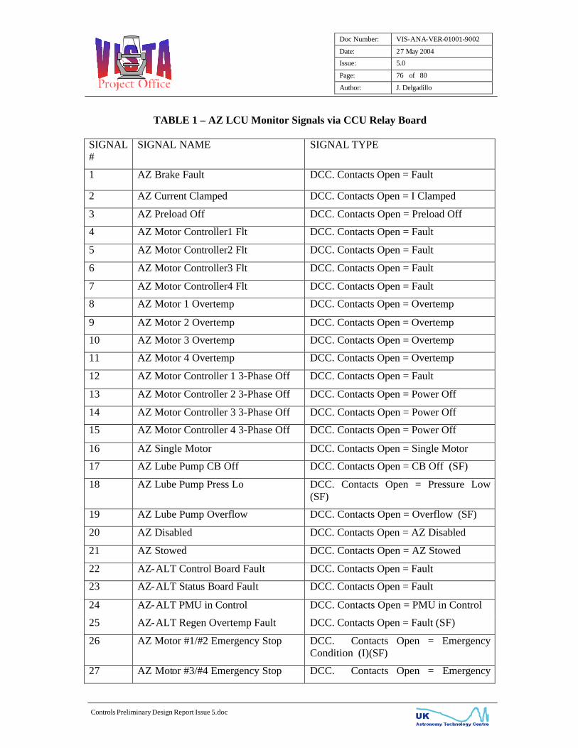
Doc Number: VIS-ANA-VER-01001-9002
Date: 27 May 2004
Issue: 5.0
Page: 76 of 80
Author: J. Delgadillo
Controls Preliminary Design Report Issue 5.doc
TABLE 1 – AZ LCU Monitor Signals via CCU Relay Board
SIGNAL #
SIGNAL NAME SIGNAL TYPE
1 AZ Brake Fault DCC. Contacts Open = Fault
2 AZ Current Clamped DCC. Contacts Open = I Clamped
3 AZ Preload Off DCC. Contacts Open = Preload Off
4 AZ Motor Controller1 Flt DCC. Contacts Open = Fault
5 AZ Motor Controller2 Flt DCC. Contacts Open = Fault
6 AZ Motor Controller3 Flt DCC. Contacts Open = Fault
7 AZ Motor Controller4 Flt DCC. Contacts Open = Fault
8 AZ Motor 1 Overtemp DCC. Contacts Open = Overtemp
9 AZ Motor 2 Overtemp DCC. Contacts Open = Overtemp
10 AZ Motor 3 Overtemp DCC. Contacts Open = Overtemp
11 AZ Motor 4 Overtemp DCC. Contacts Open = Overtemp
12 AZ Motor Controller 1 3-Phase Off DCC. Contacts Open = Fault
13 AZ Motor Controller 2 3-Phase Off DCC. Contacts Open = Power Off
14 AZ Motor Controller 3 3-Phase Off DCC. Contacts Open = Power Off
15 AZ Motor Controller 4 3-Phase Off DCC. Contacts Open = Power Off
16 AZ Single Motor DCC. Contacts Open = Single Motor
17 AZ Lube Pump CB Off DCC. Contacts Open = CB Off (SF)
18 AZ Lube Pump Press Lo DCC. Contacts Open = Pressure Low (SF)
19 AZ Lube Pump Overflow DCC. Contacts Open = Overflow (SF)
20 AZ Disabled DCC. Contacts Open = AZ Disabled
21 AZ Stowed DCC. Contacts Open = AZ Stowed
22 AZ-ALT Control Board Fault DCC. Contacts Open = Fault
23 AZ-ALT Status Board Fault DCC. Contacts Open = Fault
24 AZ-ALT PMU in Control DCC. Contacts Open = PMU in Control
25 AZ-ALT Regen Overtemp Fault DCC. Contacts Open = Fault (SF)
26 AZ Motor #1/#2 Emergency Stop DCC. Contacts Open = Emergency Condition (I)(SF)
27 AZ Motor #3/#4 Emergency Stop DCC. Contacts Open = Emergency

Doc Number: VIS-ANA-VER-01001-9002
Date: 27 May 2004
Issue: 5.0
Page: 77 of 80
Author: J. Delgadillo
Controls Preliminary Design Report Issue 5.doc
Condition (I)(SF)
28 ALT Motor #1 Emergency Stop DCC. Contacts Open = Emergency Condition (I)(SF)
29 ALT Motor #2 Emergency Stop DCC. Contacts Open = Emergency Condition (I)(SF)
30 ALT Pier Emergency Stop DCC. Contacts Open = Emergency Condition (I)(SF)
31 Equipment Room Emergency Stop DCC. Contacts Open = Emergency Condition (I)(SF)
32 Cone Emergency Stop DCC. Contacts Open = Emergency Condition (I)(SF)
33 Common Isolated Return for above contacts
DCC – Dry-Contact Closure (I) – Causes Interlock (SF) – Causes Summary Fault
TABLE 2 – ALT LCU Monitor Signals via CCU Relay Board SIGNAL #
SIGNAL NAME SIGNAL TYPE
1 ALT Brake Fault DCC. Contacts Open = Fault (SF)
2 ALT Current Clamped DCC. Contacts Open = I Clamped
3 ALT Motor Controller1 Flt DCC. Contacts Open = Fault
4 ALT Motor Controller2 Flt DCC. Contacts Open = Fault
5 ALT Motor 1 Overtemp DCC. Contacts Open = Overtemp
6 ALT Motor 2 Overtemp DCC. Contacts Open = Overtemp
7 ALT Motor Controller 1 3-Phase Off DCC. Contacts Open = Power Off
8 ALT Motor Controller 2 3-Phase Off DCC. Contacts Open = Power Off
9 ALT Single Motor DCC. Contacts Open = Single Motor
10 ALT Disabled DCC. Contacts Open = ALT Disabled
11 ALT Stowed DCC. Contacts Open = ALT Stowed
12 AZ-ALT Control Board Fault DCC. Contacts Open = Fault
13 AZ-ALT Status Board Fault DCC. Contacts Open = Fault
14 AZ-ALT PMU in Control DCC. Contacts Open = PMU in Control
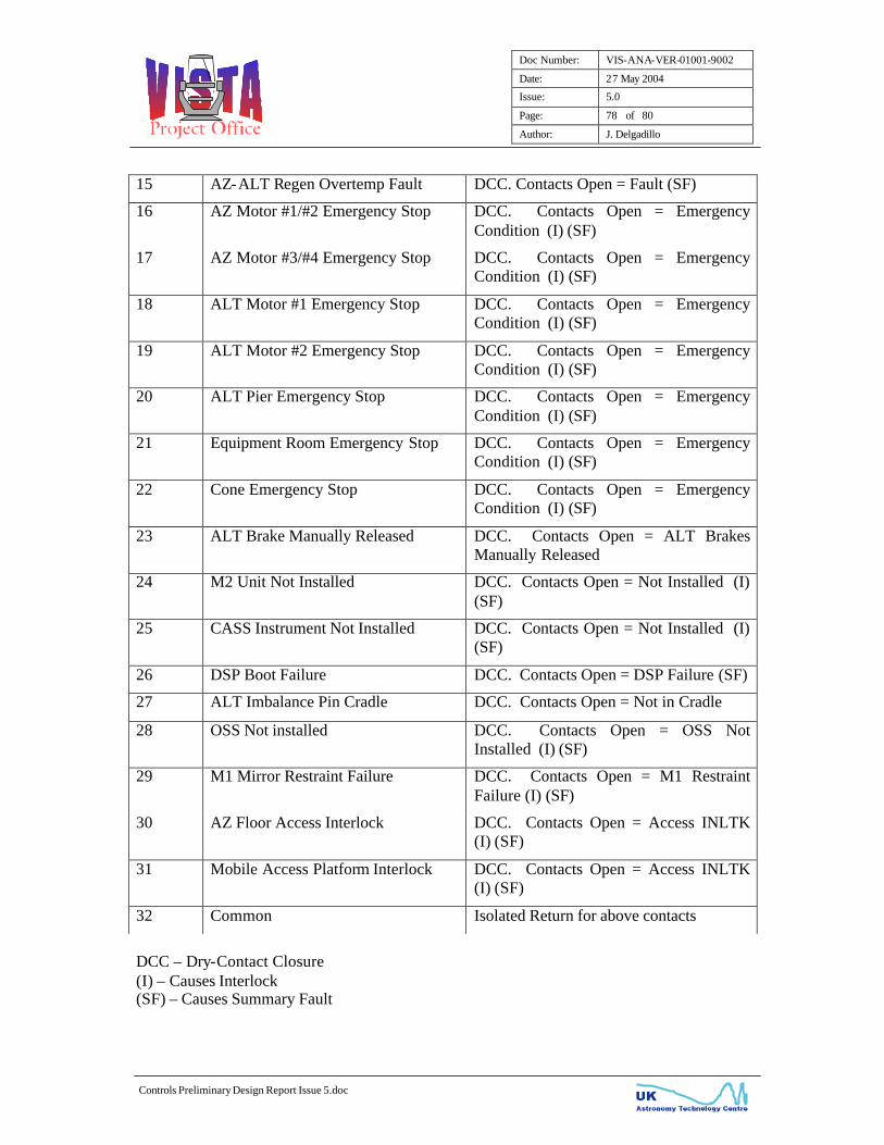
Doc Number: VIS-ANA-VER-01001-9002
Date: 27 May 2004
Issue: 5.0
Page: 78 of 80
Author: J. Delgadillo
Controls Preliminary Design Report Issue 5.doc
15 AZ-ALT Regen Overtemp Fault DCC. Contacts Open = Fault (SF)
16 AZ Motor #1/#2 Emergency Stop DCC. Contacts Open = Emergency Condition (I) (SF)
17 AZ Motor #3/#4 Emergency Stop DCC. Contacts Open = Emergency Condition (I) (SF)
18 ALT Motor #1 Emergency Stop DCC. Contacts Open = Emergency Condition (I) (SF)
19 ALT Motor #2 Emergency Stop DCC. Contacts Open = Emergency Condition (I) (SF)
20 ALT Pier Emergency Stop DCC. Contacts Open = Emergency Condition (I) (SF)
21 Equipment Room Emergency Stop DCC. Contacts Open = Emergency Condition (I) (SF)
22 Cone Emergency Stop DCC. Contacts Open = Emergency Condition (I) (SF)
23 ALT Brake Manually Released DCC. Contacts Open = ALT Brakes Manually Released
24 M2 Unit Not Installed DCC. Contacts Open = Not Installed (I) (SF)
25 CASS Instrument Not Installed DCC. Contacts Open = Not Installed (I) (SF)
26 DSP Boot Failure DCC. Contacts Open = DSP Failure (SF)
27 ALT Imbalance Pin Cradle DCC. Contacts Open = Not in Cradle
28 OSS Not installed DCC. Contacts Open = OSS Not Installed (I) (SF)
29 M1 Mirror Restraint Failure DCC. Contacts Open = M1 Restraint Failure (I) (SF)
30 AZ Floor Access Interlock DCC. Contacts Open = Access INLTK (I) (SF)
31 Mobile Access Platform Interlock DCC. Contacts Open = Access INLTK (I) (SF)
32 Common Isolated Return for above contacts
DCC – Dry-Contact Closure (I) – Causes Interlock (SF) – Causes Summary Fault
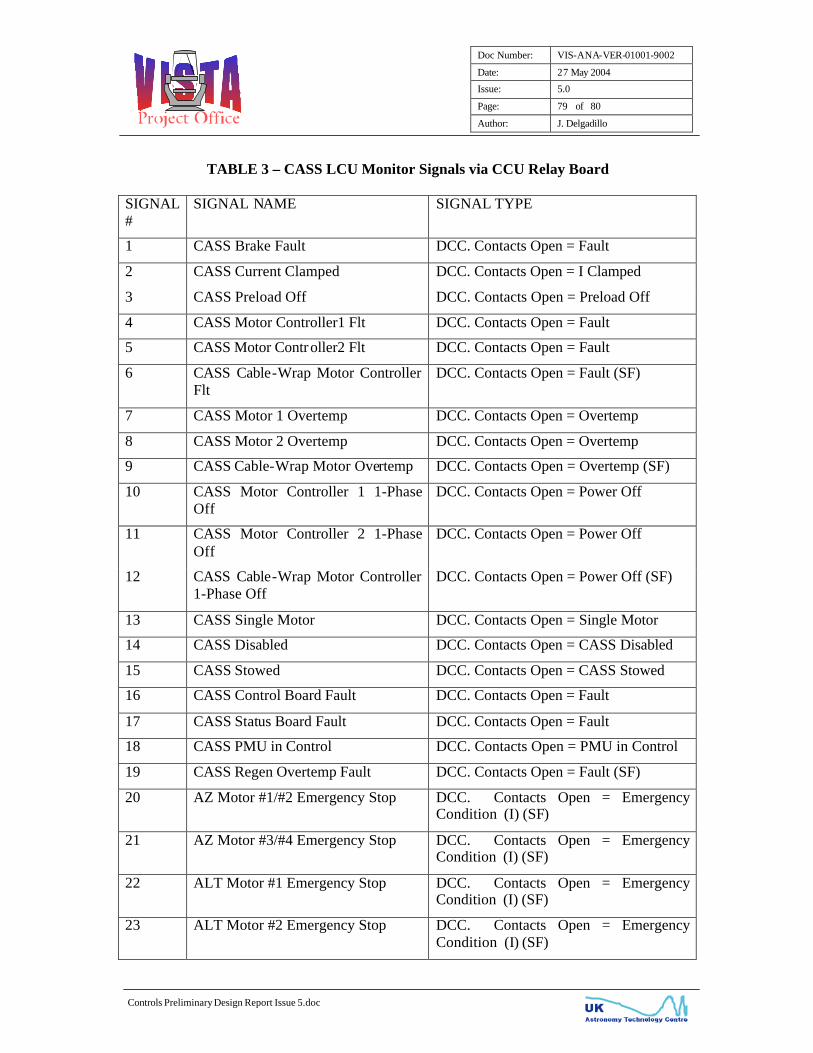
Doc Number: VIS-ANA-VER-01001-9002
Date: 27 May 2004
Issue: 5.0
Page: 79 of 80
Author: J. Delgadillo
Controls Preliminary Design Report Issue 5.doc
TABLE 3 – CASS LCU Monitor Signals via CCU Relay Board SIGNAL #
SIGNAL NAME SIGNAL TYPE
1 CASS Brake Fault DCC. Contacts Open = Fault
2 CASS Current Clamped DCC. Contacts Open = I Clamped
3 CASS Preload Off DCC. Contacts Open = Preload Off
4 CASS Motor Controller1 Flt DCC. Contacts Open = Fault
5 CASS Motor Controller2 Flt DCC. Contacts Open = Fault
6 CASS Cable-Wrap Motor Controller Flt
DCC. Contacts Open = Fault (SF)
7 CASS Motor 1 Overtemp DCC. Contacts Open = Overtemp
8 CASS Motor 2 Overtemp DCC. Contacts Open = Overtemp
9 CASS Cable-Wrap Motor Overtemp DCC. Contacts Open = Overtemp (SF)
10 CASS Motor Controller 1 1-Phase Off
DCC. Contacts Open = Power Off
11 CASS Motor Controller 2 1-Phase Off
DCC. Contacts Open = Power Off
12 CASS Cable-Wrap Motor Controller 1-Phase Off
DCC. Contacts Open = Power Off (SF)
13 CASS Single Motor DCC. Contacts Open = Single Motor
14 CASS Disabled DCC. Contacts Open = CASS Disabled
15 CASS Stowed DCC. Contacts Open = CASS Stowed
16 CASS Control Board Fault DCC. Contacts Open = Fault
17 CASS Status Board Fault DCC. Contacts Open = Fault
18 CASS PMU in Control DCC. Contacts Open = PMU in Control
19 CASS Regen Overtemp Fault DCC. Contacts Open = Fault (SF)
20 AZ Motor #1/#2 Emergency Stop DCC. Contacts Open = Emergency Condition (I) (SF)
21 AZ Motor #3/#4 Emergency Stop DCC. Contacts Open = Emergency Condition (I) (SF)
22 ALT Motor #1 Emergency Stop DCC. Contacts Open = Emergency Condition (I) (SF)
23 ALT Motor #2 Emergency Stop DCC. Contacts Open = Emergency Condition (I) (SF)

Doc Number: VIS-ANA-VER-01001-9002
Date: 27 May 2004
Issue: 5.0
Page: 80 of 80
Author: J. Delgadillo
Controls Preliminary Design Report Issue 5.doc
24 ALT Pier Emergency Stop DCC. Contacts Open = Emergency Condition (I) (SF)
25 Equipment Room Emergency Stop DCC. Contacts Open = Emergency Condition (I) (SF)
26 Cone Emergency Stop DCC. Contacts Open = Emergency Condition (I) (SF)
27 Common Isolated Return for above contacts
DCC – Dry-Contact Closure (I) – Causes Interlock (SF) – Causes Summary Fault