Embed Size (px)
Citation preview

Controlling distributed audio from a
3D Graphical User Interface (GUI)
Submitted in partial fulfilment of the requirements of thedegree
Bachelor of Science (Honours)
Computer Science
Rhodes University - Grahamstown
M. L. Hedges
2012

Abstract
There has been rapid progression from analog conventional audio networks to dig-
ital audio networks. This has been a great success with a single problem that is
increasingly growing - how do we control these networks? There are various pro-
grams available that allow a user to control distributed digital audio, however these
are not user friendly and represent the venue in a similar fashion to an architectural
blueprint.
This research investigates the feasibility of using an open source 3 Dimensional mod-
eling program called Google Sketchup in order to control a distributed digital audio
network. This was done by integrating Sketchup and a Visual C++ program which
was able to instantiate a newly developed Network Layer protocol for controlling
sound. The implementation of this research revealed that creating a user friendly
system that is capable of controlling distributed digital is attainable and can be done
so using tools that are available to most users. There is still a substantial amount of
future work that may be done in this field, which is mentioned in the last chapter.

ACM Computing Classification
System Classification
Thesis classification under the ACM Computing Classification System (1998 version,
valid through 2012)
H.5.1 [Multimedia Information Systems]: Audio Input/Output
I.2.10 [Vision and Scene understanding]: 3D/stereo scene analysis
C.2.5 [Local and Wide-Area Networks]: Ethernet
General Terms: Design, Distributed Audio

Acknowledgments
I would like to acknowledge the funding towards the Rhodes University Computer
Science Department from Telkom, THRIP, Genband, Tellabs, Easttel, and Bright
Idea Projects 39 through the Telkom Centre of Excellence in Distributed Multimedia.
I would like to acknowledge Professor Richard Foss for the guidance throughout my
honours year and the ideas and help he provided me with on a regular basis.
I would like to acknowledge my parents, Charles and Shelley Hedges, for funding
this year and allowing me the opportunity to attend a prestigious academic institu-
tion such as Rhodes University.
I would like to acknowledge Osedum Igumbor, James Dibley, and Shane Haw for
the work in the field of digital audio and providing me with sufficient resources which
made the ideas of this project a reality.

Table of Contents
1 Introduction 1
1.1 Transition from Conventional audio to Digital audio . . . . . . . . . . 1
1.2 Problem Statement and Research Goals . . . . . . . . . . . . . . . . . 2
1.2.1 Primary goals . . . . . . . . . . . . . . . . . . . . . . . . . . . 2
1.2.2 Secondary goals . . . . . . . . . . . . . . . . . . . . . . . . . . 3
1.3 Thesis Layout . . . . . . . . . . . . . . . . . . . . . . . . . . . . . . . 3
2 Graphical Sound System Control 5
2.1 UNOS Creator . . . . . . . . . . . . . . . . . . . . . . . . . . . . . . 5
2.2 Harman System Architect . . . . . . . . . . . . . . . . . . . . . . . . 6
2.2.1 Defining the venue . . . . . . . . . . . . . . . . . . . . . . . . 6
2.2.2 Adding devices by their location . . . . . . . . . . . . . . . . . 7
2.2.3 Associating the devices by their location . . . . . . . . . . . . 7
2.2.4 Routing the audio . . . . . . . . . . . . . . . . . . . . . . . . . 8
2.3 BSS London Architect . . . . . . . . . . . . . . . . . . . . . . . . . . 8
2.4 Biamp Systems’ Tesira . . . . . . . . . . . . . . . . . . . . . . . . . . 9
2.5 The Need for 3D Sound Control . . . . . . . . . . . . . . . . . . . . . 10
3 Sound System Control Protocols 12
3.1 Harman Pro HiQNet . . . . . . . . . . . . . . . . . . . . . . . . . . . 12
3.1.1 Devices, Virtual Devices, and their attributes . . . . . . . . . 12
3.1.2 Objects . . . . . . . . . . . . . . . . . . . . . . . . . . . . . . 14
3.1.3 Addressing . . . . . . . . . . . . . . . . . . . . . . . . . . . . . 15
3.1.4 Messages and Message flags . . . . . . . . . . . . . . . . . . . 16

3.2 XFN . . . . . . . . . . . . . . . . . . . . . . . . . . . . . . . . . . . . 19
3.2.1 XFN Devices . . . . . . . . . . . . . . . . . . . . . . . . . . . 19
3.2.2 XFN Networks . . . . . . . . . . . . . . . . . . . . . . . . . . 20
3.2.3 XFN Messages . . . . . . . . . . . . . . . . . . . . . . . . . . 21
3.2.4 XFN Parameters . . . . . . . . . . . . . . . . . . . . . . . . . 22
3.3 AVDECC . . . . . . . . . . . . . . . . . . . . . . . . . . . . . . . . . 23
3.3.1 The AVDECC Discovery Protocol . . . . . . . . . . . . . . . . 24
3.3.2 The AVDECC Connection Management Protocol . . . . . . . 25
3.3.3 The AVDECC Enumeration and Control Protocol . . . . . . . 27
3.3.4 Types of ADVECC Devices . . . . . . . . . . . . . . . . . . . 28
3.3.5 The Choice of AVDECC . . . . . . . . . . . . . . . . . . . . . 29
4 Google Sketchup - A Tool for 3D Design 30
4.1 Ruby . . . . . . . . . . . . . . . . . . . . . . . . . . . . . . . . . . . . 31
4.1.1 Ruby in Sketchup . . . . . . . . . . . . . . . . . . . . . . . . . 31
4.2 Predefined Ruby classes . . . . . . . . . . . . . . . . . . . . . . . . . 32
4.2.1 User Interface . . . . . . . . . . . . . . . . . . . . . . . . . . . 32
4.2.2 Cameras . . . . . . . . . . . . . . . . . . . . . . . . . . . . . . 32
4.2.3 Entities . . . . . . . . . . . . . . . . . . . . . . . . . . . . . . 35
4.2.4 SKSocket . . . . . . . . . . . . . . . . . . . . . . . . . . . . . 36
4.2.5 Geom . . . . . . . . . . . . . . . . . . . . . . . . . . . . . . . 37
5 Design of the 3D Graphical Control System 39
5.1 The Object Oriented Design . . . . . . . . . . . . . . . . . . . . . . 40
5.1.1 Requirement Specification . . . . . . . . . . . . . . . . . . . . 40
5.1.2 Use Case Diagrams . . . . . . . . . . . . . . . . . . . . . . . . 41
5.1.3 Textual Scenarios . . . . . . . . . . . . . . . . . . . . . . . . . 45
5.1.4 Class Diagram / Object Model . . . . . . . . . . . . . . . . . 46
5.1.5 Sequence Diagrams . . . . . . . . . . . . . . . . . . . . . . . . 49
5.1.6 Overview . . . . . . . . . . . . . . . . . . . . . . . . . . . . . 50
5.2 The SkAv Protocol . . . . . . . . . . . . . . . . . . . . . . . . . . . . 50

6 Implementation and Operational Highlights of the 3D
Graphical Control System 52
6.1 Visual C++ . . . . . . . . . . . . . . . . . . . . . . . . . . . . . . . . 52
6.1.1 Socket Connections . . . . . . . . . . . . . . . . . . . . . . . . 52
6.1.2 Sending and Receiving SkAv Messages . . . . . . . . . . . . . 53
6.1.3 Initiating Discovery . . . . . . . . . . . . . . . . . . . . . . . . 55
6.1.4 AVDECC Discovery . . . . . . . . . . . . . . . . . . . . . . . 56
6.1.5 Creating a Stream . . . . . . . . . . . . . . . . . . . . . . . . 58
6.1.6 Converting from String to MAC . . . . . . . . . . . . . . . . . 59
6.1.7 Streaming Audio . . . . . . . . . . . . . . . . . . . . . . . . . 60
6.2 Ruby . . . . . . . . . . . . . . . . . . . . . . . . . . . . . . . . . . . . 61
6.2.1 Parsing the Messages from Visual C++ . . . . . . . . . . . . . 61
6.2.2 Creating Atterotech Boards . . . . . . . . . . . . . . . . . . . 62
6.2.3 Converting from Atterotech Boards to Talkers and Listeners . 63
6.2.4 Sending the Device MAC Addresses for Stream Request . . . 64
7 Conclusion 66
7.1 Analysis of Goals . . . . . . . . . . . . . . . . . . . . . . . . . . . . . 66
7.2 Future work . . . . . . . . . . . . . . . . . . . . . . . . . . . . . . . . 67
7.2.1 Scaling the System . . . . . . . . . . . . . . . . . . . . . . . . 68
7.2.2 Maximizing Automation . . . . . . . . . . . . . . . . . . . . . 68
7.2.3 Implementing the AVDECC Enumeration and Control Protocol 68
Bibliography 74

List of Figures
2.1 UNOS Vision device discovery [25] . . . . . . . . . . . . . . . . . . . 6
2.2 Placing devices in System Architect [27] . . . . . . . . . . . . . . . . 7
2.3 The London Architect user interface . . . . . . . . . . . . . . . . . . . 9
2.4 The Tesira user interface . . . . . . . . . . . . . . . . . . . . . . . . . 10
2.5 A sample venue drawn in sketchup - two speakers and an amplifier
are shown . . . . . . . . . . . . . . . . . . . . . . . . . . . . . . . . . 11
3.1 Attributes in the HiQNet Device manager . . . . . . . . . . . . . . . 13
3.2 HiQNet Device Architecture . . . . . . . . . . . . . . . . . . . . . . . 14
3.3 HiQNet Addressing [28] . . . . . . . . . . . . . . . . . . . . . . . . . 15
3.4 HiQNet address levels shown with their ID . . . . . . . . . . . . . . . 16
3.5 The message header for HiQNet messages [28] . . . . . . . . . . . . . 17
3.6 Sample layout of an XFN network (Apdapted from [22]) . . . . . . . 21
3.7 Message header for an XFN message [22] . . . . . . . . . . . . . . . . 22
3.8 AVDECC protocol layout showing sub protocol interaction with the
controller [32] . . . . . . . . . . . . . . . . . . . . . . . . . . . . . . . 23
3.9 The packet structure of a single AVDECC Discovery Protocol Data
Unit (ADPDU) [19] . . . . . . . . . . . . . . . . . . . . . . . . . . . . 24
3.10 The packet structure of a single AVDECC Connection Management
Protocol Data Unit (ACMPDU) [19] . . . . . . . . . . . . . . . . . . 26
3.11 The packet structure of a single AVDECC Enumeration and Control
Protocol Data Unit (AECPDU) [19] . . . . . . . . . . . . . . . . . . . 27
4.1 The User Interface message box, showing camera attributes . . . . . . 34

5.1 The Use Case Diagram for Google Sketchup . . . . . . . . . . . . . . 42
5.2 The Use Case Diagram for Visual C++ . . . . . . . . . . . . . . . . . 44
5.3 The 3D sound system’s class diagram . . . . . . . . . . . . . . . . . . 47
5.4 Sequence diagram for displaying venue on startup . . . . . . . . . . . 49
7.1 Sketchup Sequence 1 - Moving a device . . . . . . . . . . . . . . . . . 69
7.2 Sketchup Sequence 2 - Moving a camera using plugins . . . . . . . . . 70
7.3 Sketchup Sequence 3 - Moving a camera using the tools . . . . . . . . 70
7.4 Sketchup Sequence 4 - Making a stream connection . . . . . . . . . . 71
7.5 Sketchup Sequence 5 - Controlling a device . . . . . . . . . . . . . . . 71
7.6 Visual C++ Sequence 1 - Discovering devices . . . . . . . . . . . . . 72
7.7 Visual C++ Sequence 2 - Creating a stream connection . . . . . . . . 72
7.8 Visual C++ Sequence 3 - Controlling a device . . . . . . . . . . . . . 73

1
Chapter 1
Introduction
The human race has gone through various ”Ages” and is now in the 21st century
which is referred to as the ’Digital age’ or ’Information age’. This age recognizes
that the generation of wealth and exercise of power is dependent on the capacity of
information technologies [31].
Many of the technologies from the past few decades have been adapted so they can
now be controlled by computers or computer based systems. The implementation of
distributed audio has now followed this trend as we are increasingly seeing the use of
computers and computer networking for the distribution of audio.
1.1 Transition from Conventional audio to Digital audio
There are significant advantages to using digital audio as opposed to the conven-
tional analog audio systems. There are three disadvantages to conventional audio
distribution that have contributed to the transition to digital∗ [22].
• Cost: For the bigger venues requiring larger distribution, the cabling required
costs a large amount of money. In the case of digital audio networking, multiple
channels of audio would be transmitted along a single Category 5 Ethernet
cable. .
• Weight: As mentioned in the point above, the amount of cabling for conven-
tional audio is a lot more than that of a digital audio networked. Each wire in a
conventional audio network carries a single channel, so a cable ’snake’ has to be
∗For statistical purposes, the SATSS-32x1530 - 32 Channel Send XLR Splitter Snake Cable was
used [20]

2
used that exceeds the maximum amount of channels used in the network. The
weight of a 32 channel ’snake’ cable of 150 feet (46 meters) is approximately 70
pounds (32 kilograms) as opposed to a Category 5 Ethernet cable that weighs
approximately 22 pounds (10 kilograms) per 1000 feet (305 meters). The weight
factor of conventional cables can hinder the portability of the system and this
is the reason that digital networks are preferred.
• Availability: Cable ’snakes’ are manufactured by highly specialized audio com-
panies. In contrast, category 5 Ethernet cable is readily available in almost any
town or city in any country. It is a non specialized item and is used widely in
businesses, educational institutions, households, and many more. At live con-
certs there is a high chance of cables being damaged as the venues are normally
in open areas where the cables are vulnerable to various threats, so a broken
cable could cause many problems.
1.2 Problem Statement and Research Goals
The main research involved in this project involved an in-depth look at the current
programs that control digital audio in large institutions, and whether they could
control distributed digital audio from a 3 Dimensional (3D) graphical user interface.
The research showed that the only sound control systems were from a 2D ”blueprint”
layout and that there were none that offered the capabilities of controlling the audio
from a 3D interface where the user could move around the venue in ”real time” and
control the devices.
Given the limitation of conventional sound systems, a decision was taken to harness
the power of Google Sketchup [3] to provide the 3D representation of a venue. With
this in mind, the following goals were determined:
1.2.1 Primary goals
• Discover the audio devices on the network and display them in the 3D environ-
ment provided by Google Sketchup

3
• Create audio streams between devices that have been made ”talkers” and ”lis-
teners” on the network. The interaction to create the stream was to be done
purely within the 3D environment.
• Implement a sound control protocol and have it communicate directly to Sketchup
through the use of Transmission Control Protocol (TCP) sockets.
1.2.2 Secondary goals
• Enable the user to control remote values such as volume of the devices from the
main control interface.
• Test whether the system is scalable in terms of numbers and distribution of
devices.
1.3 Thesis Layout
The layout of the remaining contents of the thesis is described below.
Chapter 2 - The current sound system control programs are discussed in this chap-
ter. A brief overview of each one is given, followed by the need for a 3D graphical
sound system program.
Chapter 3 - This chapter describes the current protocols that are being used to
control digital audio and why the AVDECC protocol was chosen for this specific
project.
Chapter 4 - The capabilities and plugins for Google Sketchup are discussed in this
chapter along with the possibility of its interaction with the Visual C++ component
of the project.
Chapter 5 - This chapter describes the design of the system, the process involved
in finalizing the design, and the importance of the design in a project such as this one.

4
Chapter 6 - The implementation of the project is discussed in this chapter. In-
cluded in this chapter are methods used on both the Sketchup and C++ side of the
system, descriptions of what they do, and how they help the system reach the final
goals.
Chapter 7 - This chapter summarizes the project and discusses any future work
that could be done to improve the system.
5
Chapter 2
Graphical Sound System Control
Graphical sound system control is a rapidly developing field of research due to the
increase in popularity of digital audio streaming rather than analog. Graphical sound
control also allows the user to control the various networked devices from a central-
ized point. This is a lot less consuming in terms of resources when comparing it to
the conventional way of controlling analog audio, which would be to have sound tech-
nicians stationed at various points of the venue - each performing a specific activity.
There are currently several programs that offer graphical sound control over net-
worked audio and they are discussed below. These are all easily available and a full
or trial version may be downloaded off the internet from their respective websites.
2.1 UNOS Creator
UNOS Creator is sound installation software developed by Universal Media Access
Networks (UMAN). It’s core functionality is the ability to create custom interfaces
by drag and drop instead of writing lines of code for an interface [21]. UNOS Creator
provides the user with a desk item editing capability, which allows the user to specify
various images for the different desk item controls. Desk item controls are controls
that are found on a desk top such as sliders and meters [25]. Each desk item has a
parameter associated with it which is known as a ”control parameter”. This effectively
controls the value associated with the desk item [25].
The UNOS Creator GUI editor can be accessed from the ”tools” menu within UNOS
Vision. UNOS Vision displays different devices for the various subnet configurations.
The devices can then be selected to display the ’matrix view’ which enables control
and patching of the devices [25].

6
Figure 2.1 : UNOS Vision device discovery [25]
2.2 Harman System Architect
System Architect is a software application developed by the Harman group to control
HiQNet systems. It is the user interface for the HiQNet protocol, discussed in section
3.1. Sound control can take place once the software has been configured to match the
network layout. This can be done in the four steps shown below [27].
2.2.1 Defining the venue
The user is required to graphically design the venue for the sound installation. This
can be done by using the pre-set shapes provided by System Architect which can be
shaped into a realistic representation of the venue. A crucial feature that enables this
is the capability of having a background image whilst creating the layout, effectively
allowing the user to ”trace” the layout of the venue.

7
2.2.2 Adding devices by their location
After the venue design is completed, the user will then add the distributed audio
devices to the venue. These can be specifically placed as they will correspond to
their physical location within the venue. The list of devices provided by System
Architect is pre-set and includes various devices by AKG, BSS, Crown, dbx, JBL,
and Lexicon [29]. The physical layout of the devices is important as the interface will
indicate which rooms have problems (if they occur).
Figure 2.2 : Placing devices in System Architect [27]
2.2.3 Associating the devices by their location
Although sound sourced (eg. Microphone Preamp) have only one physical location,
they can be connected to multiple sound sources [27]. This stage of the setup involves
the user specifying which amplifiers are connected to speakers in different sections of
the venue. System Architect provides a drag and drop technique to allow the user to
specify which amplifier channels to connect on installation.
8
2.2.4 Routing the audio
Audio routing is a highly complex step within general sound installation. System
Architect has aimed to simplify it by allowing the user to route to specific zones
within the venue, instead of specific devices. This is a high level abstraction as the
”behind the scenes” device routing is all taken care of.
2.3 BSS London Architect
London Architect, developed by BSS audio, is software that uses the HiQNet protocol
and allows for graphical sound installation [16]. London Architect is a powerful tool
which makes use of a user orientated drag and drop GUI. It provides standard sets of
audio devices for the user to add to the interface and simply connect to other devices.
The software provides a wide range of functions which allow scheduling as well as
automatic system adjustments according to the state of the devices [16].
Despite the difference between the interface appearances, this software is in many
ways similar to System Architect. There is one major difference in that System
Architect allows connection between zones, while London Architect allows explicit
connection between devices. The London Architect device interface shows all the
input and output jacks for the list of preset devices, which allows the user to specify
exactly which inputs and outputs are connected between devices. System Architect
does all this for the user ”behind the scenes”, which is ideal from a ’user friendliness’
point of view, but gives less direct control over the devices. Figure 2.3 shows the
device layout in an audio network being controlled by London Architect.

9
Figure 2.3 : The London Architect user interface
2.4 Biamp Systems’ Tesira
Biamp Systems is a company that provides digital audio solutions to large scale venues
such as conference centres, airports, and theatres. They create their own products
from initial Digital Signal Processing (DSP) to the software implementation [1]. Their
latest product, ’Tesira’, was launched in 2011 and is the successor to ’daVinci’ which
was launched in 2006 [1].
Tesira’s main focus is scalability of audio solutions. It aims to provide high quality
audio solutions starting with single room networked audio solutions (such as a confer-
ence room) up to audio systems that span over several buildings [14]. These could all
be controlled by using a single terminal with the Tesira software installed, although
for the larger solutions it would be beneficial to have more than one control station.
The Tesira user interface is similar to BSS London Architect except with a more

10
modern, user friendly appearance. Devices may be placed around the venue and sev-
eral layers can be constructed with different devices. This layered approach simplifies
control and allows specific devices to be isolated according the the users requirement.
Connections can then be established between the inputs and outputs of the various
devices and the connections can be muted and controlled by the user interacting with
the matrix controls provided. The Tesira product range includes network expanders
which in turn allow the network to be scaled easily without any major difficulties [14].
Figure 2.4 : The Tesira user interface
2.5 The Need for 3D Sound Control
All the above-mentioned solutions provide similar services to the end user, they all
allow the user to control distributed digital audio from a centralized point. The user
interface allows the user to create a 2-dimensional layout of the networked devices
from a top-down point of view. In the case of System Architect, you are able to design
the layout of the venue with the separate rooms that contain the audio devices and

11
route the audio between rooms, but even this is done from an architectural blueprint
(2-dimensional) point of view.
The purpose of this research was to investigate the feasibility of using a 3D User
interface to control digital audio. There is no current software that allows the user
to design the venue themselves in a 3D interface and use it to control audio. Such a
view would allow the user to see the venue from a more realistic point of view and
allow them to move around the venue and control the devices from the various rooms.
Given below is a sample venue drawn using Google Sketchup - the tool that will be
used for the implementation of this project.
Figure 2.5 : A sample venue drawn in sketchup - two speakers and an amplifier areshown

12
Chapter 3
Sound System Control Protocols
This section will look at three different sound control protocols for monitoring and
controlling distributed audio devices. These three protocols are the Harman HiQNet,
XFN, and IEEE 1722.1 AVDECC. The reason these protocols have been chosen is
that the HiQNet and XFN user interfaces have been discussed in the previous chap-
ter. AVDECC has been included in this chapter as it is the protocol being used for
implementation in this project.
3.1 Harman Pro HiQNet
The HiQNet protocol, developed by the Harman group, is aimed at a single solution
for all Harman networked devices [12]. It is controlled by a single application, System
Architect, which has been developed to comply with the specification of this protocol
in order to optimize both tour sound and sound installation environments [17]. This
protocol has a tiered approach with the top level representing the actual device (node)
where each node must have at least one virtual device; this acts as a node manager.
3.1.1 Devices, Virtual Devices, and their attributes
A single device describes the physical product (A networked digital audio device) itself
where each device is made up of one or more Virtual Devices [28]. Each virtual device
(as well as the objects in the virtual devices) can contain objects and parameters.
These make up a useful unit which allows designers a convenient method of segmenting
the product. Each device must have at least one virtual device which is the Device
Manager, which contains attributes describing the actual device.

13
Figure 3.1 : Attributes in the HiQNet Device manager
At each level in the hierarchy there are also attributes, which are member vari-
ables containing data about the virtual device, parameters or objects. Attributes can
be classed into three different types, which are static, instance, or instance & dy-
namic. Static variables contain the same values across all the different devices of the
same model. Instance variables are initialized on start up and have their values set,
while the instance & dynamic are set on start up and can have their values changed
throughout their lifetime.
Each item (Virtual device, object, or parameter) has its own unique Class ID and
Class Name. This allows each one to be uniquely identified in order for the designer
to work with them individually [28]. Given below is the architecture found in all
HiQNet devices.

14
Figure 3.2 : HiQNet Device Architecture
3.1.2 Objects
Objects in HiQNet are collections of parameters or other objects conveniently grouped
together. The smallest modifiable attribute is held within a HiQNet parameter,
HiQNet parameters contain various attributes of the audio objects such as frequencies
or fader values. The number of parameters contained within the product will differ
depending on the complexity of the product, products such as mixing consoles will
have many parameters while the simpler products will only have a few. Changing
values of parameters can be done via ’set’ methods provided while retrieving the pa-
rameter values can be done using the ’get’ methods provided [28]. The ’get’ and ’set’
methods would be available depending on the device and the parameter and they
ensure that the caller has appropriate access permission. These parameters support
several primitive data types and when sending a HiQNet message, it is important to
use the appropriate data format [28].

15
3.1.3 Addressing
HiQNet’s addressing is split into three levels, which are shown in order below along
with each of their sizes (in bits).
Figure 3.3 : HiQNet Addressing [28]
HiQNet Device address
This is the highest level address which is a 16 bit long integer value. This begins at
1 and increments with each device added. These addresses can be seen next to the
respective device’s name in the System Explorer on the System Architect’s interface.
It can also be seen in the venue view when all the devices are listed [28].
Virtual Device address and Object address
The 8 bit Virtual Device address along with the 24 bit long Object address form
the second level address which is 32 bits long. The virtual device address is also an
integer value which starts at 0 and increments for each virtual device in the actual
device. The first device (with the Virtual Device address of 1) is the Device Manager.
The Object address is broken into three eight-bit integer values separated by the full
stop character. Each of these are unique to their respective virtual device.
Parameter Index
The Parameter index is represented as an integer starting at 0 and incrementing with
each parameter within the specific object of the virtual device.
16
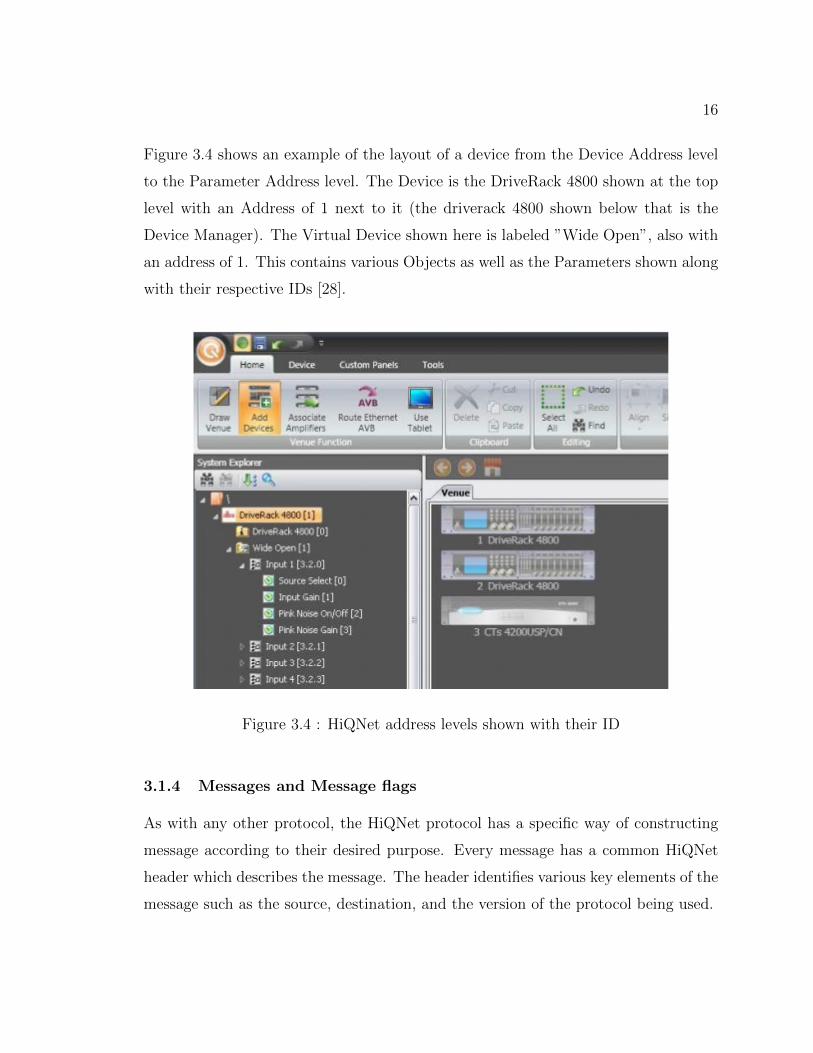
Figure 3.4 shows an example of the layout of a device from the Device Address level
to the Parameter Address level. The Device is the DriveRack 4800 shown at the top
level with an Address of 1 next to it (the driverack 4800 shown below that is the
Device Manager). The Virtual Device shown here is labeled ”Wide Open”, also with
an address of 1. This contains various Objects as well as the Parameters shown along
with their respective IDs [28].
Figure 3.4 : HiQNet address levels shown with their ID
3.1.4 Messages and Message flags
As with any other protocol, the HiQNet protocol has a specific way of constructing
message according to their desired purpose. Every message has a common HiQNet
header which describes the message. The header identifies various key elements of the
message such as the source, destination, and the version of the protocol being used.

17
Figure 3.5 : The message header for HiQNet messages [28]
Although a lot of the fields above remain constant for this version of the pro-
tocol, there are a few important ones that need to be set in order for the message
to successfully be delivered. The ’Source address’ and ’Destination address’ are the
most important as they show the sender and recipient of the message. The ’Header
length’ field is the size of the entire header, including any additional headers [28].
The ’Message length’ field, similar to ’Header length’, contains the length of the en-
tire mesage from the last byte of the header to the last byte of the payload [28].
There are optional parts of the message header which include error headers, multi-
part headers, and session number headers [28]. These have their own unique fields
and can be shown what type of message they are by the ”Flags” field in the main
message header. The ”Flags” field is a 16 bit long field, each bit being either a flag,
or reserved for future use. The flags are then set depending on what type of message
it is, for example if the message was an acknowledgment, the first bit would be set,
informing the recipient that this message is an acknowledgment [28].
There are various types of messages that are sent between devices, each requesting
an action from the recipient. Listed below are the messages that are able to be sent
and received between HiQNet networked devices [28].
18
Request Acknowledgement Message
This message is sent to a device checking whether it has performed an action which
was requested in a previous message. This is done by using a ”ReqAck” flag in the
message which lets the recipient know that an ”Ack” is being requested. If this is
successful, the recipient will send the message back to the sender with the ReqAck
flag cleared and the Ack flag set. This message provides a mechanism that allows the
protocol to function efficiently and consistently [28].
Information Message Flag
The information flag is used to show that the message is the response to a particular
request. This allows the response to match the request, however it has the information
flag set. An example of this would be a get request, the response would also be a ’get’
message with the information flag set, letting the sender know that it is an information
message. This will then have the value requested appended in the payload of the
information message [28].
Error Message Flag
The error flag is set when an error has occurred between two devices. The recipient
will simply set the error flag of the original message and send that back to the sender.
Guaranteed Message Flag
This flag may be set if the receipt of a message is critical. This will transfer the
priority of the message from fast delivery to guaranteed delivery by not using the
datagram service to transmit it.
Multi-part Message Flag
This flag shows that a message will be sent through in various packets, which is ex-
tended by the use of the multi-part header. Various steps have to be taken when
sending a multi-part message such as the ’Bytes Remaining’ field being continuously

19
updated, and the ”Sequence Number” field being incremented. The ”Bytes Remain-
ing” refers solely to the size of the payload and does not include the headers.
3.2 XFN
The XFN (Cross Fire Network) Protocol is an IP based peer-to-peer network layer [34]
command and control protocol [22] [26]. This protocol has two broad functionalities,
which are connection management, monitoring, and controlling devices [30].
3.2.1 XFN Devices
A device must satisfy two prerequisites in order to use the XFN protocol, which are
as follows:
• It must have at least one fully functional networking interface
• It must incorporate an IP stack
Devices are discovered on an XFN network by the use of broadcast messages. These
are messages addressed with wildcard destination addresses and request parameters
such as the node ID and IP address [36]. Each XFN device within a network is rep-
resented as a hierarchical, seven level tree of device parameters. Due to the structure
of the tree, each parameter in an XFN network must be addressed via the fixed seven
level address. Each level has a unique value assigned to it, with an associated alias
in order to describe its functionality [26].
The seven levels of the hierarchy are described below, in descending order.
1. Section Block: Any single device may be a composition of various sections such
as output or patching [26]. This part of the hierarchy is used for identifying the
section in which parameters are contained.
2. Section Type: This identifies the distinct type of the section. The output of a
mixing console may have digital or analogue output so it is important to distinguish
the type [26]
20
3. Section Number: The section number is used to identify specific instances of
the section [26]. A mixing console may have an output section with various channels
that need to be individually addressed [30].
4. Parameter Block: The parameter block is used to designate a block of param-
eters with similar functionality. This section may be less critical for simpler devices
which contain a single block of various parameters [30]
5. Parameter Block Index: The parameter block index is used to refer to different
subsections of the parameter block [26]. This may follow the Parameter Block closely
and is also negligible for simpler devices [30].
6. Parameter Type: The parameter type describes the type of parameter being
addressed [26]. There can be many different types of parameters within a single
device such as frequency or gain, which needs to be addressed individually [30].
7. Parameter Index: The parameter index is the lowest level in the hierarchy, and
distinguishes between parameters of the same types.
3.2.2 XFN Networks
An XFN network is simply an IP network of XFN devices with at least one XFN
controller. This controller can be described as an XFN device that provides a Graph-
ical User Interface (GUI) that the user may interact with such as an iPad, desktop
computer, or smart phone [22]. The controller will appear to other networked devices
as another XFN device, while the user is able to interact with it and use it to control
the parameters of the other FN devices on the network [22].

21
Figure 3.6 : Sample layout of an XFN network (Apdapted from [22])
3.2.3 XFN Messages
XFN devices are allowed to send and receive XFN messages between their networked
peers. The XFN stack provides facilities for the transmission and receipt of XFN mes-
sages according to the predefined XFN Application Programming Interface (API) [24].
Every XFN message can be classed as either a request or a response. A request is a
message sent from one XFN device to another requesting an action, while the response
is a ”reply” to a request message [30]. An XFN message may be targeted at a single
device or can be broadcast to many different devices on the network at once [22]. Not
every request message has a response; this is purely determined by the nature of the
message. In some of the XFN messages such as the setRemoteParamValue nonb fdb
∗, there is boolean parameter named responseRequired which may be set to true or
false depending on whether the sender requires a response or not [24].
∗A non blocking method which sends a request to set a remote parameter value [24]

22
Contained within these messages is the Command Executive and Command Quali-
fier [30] [26]. The Executive describes the fundamental nature of the message, while
the Qualifier allows it to direct at a certain attribute of a parameter [26].
Figure 3.7 : Message header for an XFN message [22]
These XFN messages may target a device as a whole, or may target single param-
eters. The source’s IP and device ID are given in each message for the case the the
original message sent requests a response [22].
3.2.4 XFN Parameters
XFN parameters are the smallest possible data structure in an XFN device and have
the fundamental purpose of holding data values. Parameters can either be classed as
control parameters and display parameters. Although there is no formal distinction
between the two, the XFN specification does provide mechanisms to support and
protect them [22].
Every XFN device contains parameters and these are created by an XFN application
through the XFN application programming interface [22]. These parameters can then
be retrieved or updated by the XFN application or by sending XFN control messages
to the device that contains the parameter the user wishes to change. The parameters
are stored using the global units type which is the type used to encapsulate various
numeric data types [22].
23
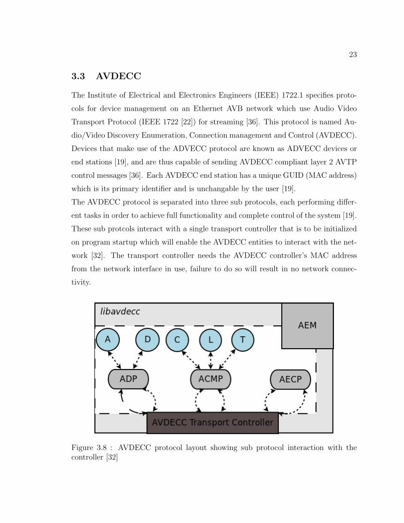
3.3 AVDECC
The Institute of Electrical and Electronics Engineers (IEEE) 1722.1 specifies proto-
cols for device management on an Ethernet AVB network which use Audio Video
Transport Protocol (IEEE 1722 [22]) for streaming [36]. This protocol is named Au-
dio/Video Discovery Enumeration, Connection management and Control (AVDECC).
Devices that make use of the ADVECC protocol are known as ADVECC devices or
end stations [19], and are thus capable of sending AVDECC compliant layer 2 AVTP
control messages [36]. Each AVDECC end station has a unique GUID (MAC address)
which is its primary identifier and is unchangable by the user [19].
The AVDECC protocol is separated into three sub protocols, each performing differ-
ent tasks in order to achieve full functionality and complete control of the system [19].
These sub protcols interact with a single transport controller that is to be initialized
on program startup which will enable the AVDECC entities to interact with the net-
work [32]. The transport controller needs the AVDECC controller’s MAC address
from the network interface in use, failure to do so will result in no network connec-
tivity.
Figure 3.8 : AVDECC protocol layout showing sub protocol interaction with thecontroller [32]

24
3.3.1 The AVDECC Discovery Protocol
The AVDECC Discovery Protocol (ADP) is a layer 2 protocol that is used to discover
AVDECC devices that are advertising on the network [19]. This protocol is able to
discover devices as they are added or removed from the network via the use of device
callbacks [32].
Discovery is based on the use of IEEE 1722 Data Units (AVTPDU) Which allows
entities to be disvocered by each other. These are known as ADPDUs and there
are three different types which indicate if an entity is ’available’, ’unavailable’, or
’searching for available’ [19]. The structure of a single ADPDU is shown below,
followed by an explanation of the most important fields in each unit.
Figure 3.9 : The packet structure of a single AVDECC Discovery Protocol Data Unit(ADPDU) [19]

25
The figure above shows the structure of an ADPDU with the fields contained in
each unit. Notable fields in this packet are as follows:
• message type: This field is also known as the ’control field’ which defines
if the entity is available, going away, or requesting an available message from
entities on the network [19].
• valid time: This field contains an even number between two and sixty-two,
which is resolved to a number between one and thirty-one. This indicates how
long the entity that transmitted the packet is valid for which results in a tradeoff
between the actual validity of the entity, and the amount of traffic generated
on the network[19].
• entity guid: This is the most important field of the packet as this contains
the unique identifier of the entity.
The rest of the fields either remained constant at this stage of the protocol develop-
ment, or were not important for the implementation of this project - therefore their
explanation was rendered irrelevant to include.
3.3.2 The AVDECC Connection Management Protocol
The AVDECC Connection Management Protocol (ACMP) is responsible for connect-
ing and disconnecting audio streams in the network. The layout for a single ACMP
Data Unit (ACMPDU) is shown in the figure below.
26
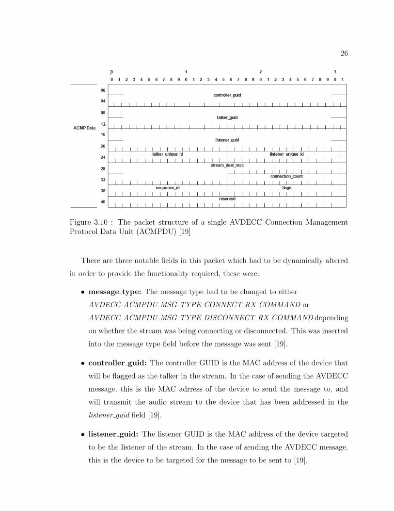
Figure 3.10 : The packet structure of a single AVDECC Connection ManagementProtocol Data Unit (ACMPDU) [19]
There are three notable fields in this packet which had to be dynamically altered
in order to provide the functionality required, these were:
• message type: The message type had to be changed to either
AVDECC ACMPDU MSG TYPE CONNECT RX COMMAND or
AVDECC ACMPDU MSG TYPE DISCONNECT RX COMMAND depending
on whether the stream was being connecting or disconnected. This was inserted
into the message type field before the message was sent [19].
• controller guid: The controller GUID is the MAC address of the device that
will be flagged as the talker in the stream. In the case of sending the AVDECC
message, this is the MAC adrress of the device to send the message to, and
will transmit the audio stream to the device that has been addressed in the
listener guid field [19].
• listener guid: The listener GUID is the MAC address of the device targeted
to be the listener of the stream. In the case of sending the AVDECC message,
this is the device to be targeted for the message to be sent to [19].

27
3.3.3 The AVDECC Enumeration and Control Protocol
The AVDECC Enumeration and Control Protocol (AECP) is responsible for discov-
ering the capabilities of the devices on the network (enumeration), and manipulating
these capabilities [19].
Figure 3.11 : The packet structure of a single AVDECC Enumeration and ControlProtocol Data Unit (AECPDU) [19]
The packet structure for this protocol is similar to that of the ACMP. Althought
this protocol wasn’t used in the implementation, there are two notable fields:
• message type: This field denotes the type of message sent, in this case they
could be commands in the payload, or commands for access and manipulation
of remote parameters [19]
• target guid: This field contains the MAC address of the device that the mes-
sage is targeted at. This is identical to the field in the ACMP packet struc-
ture [19]

28
3.3.4 Types of ADVECC Devices
Entity
An end station which facilitates transmission and receipt of AVDECC messages within
an Ethernet AVB network. This end station will typically have one network port and
provide the minimum functionality of an AVDECC entity [19].
Controller
An AVDECC entity which initiates message exchange between other entities. The
requirement for a controller is that it must be able to receive and transmit ACMP and
AECP commands. There may be more than one controller on a network, however,
the LOCK ENTITY command must be called for atomic operations.
AVDECC controllers are able to control devices as well as advertise themselves on a
network, this is to allow them to become clients to other controllers that access them
through the network layer (layer 3). Although the protocol is based on the network
layer (layer 2), it is able to interact with other entities through the network layer via
an AVDECC proxy [19]
Listener
A listener is an ADVECC entity that is the sink of an AVTP audio stream. The sink
must be able to respond to connection commands received from the ACMP as well
as respond to connection management commands from the talker [19].
Talker
An AVDECC entity which allows transmission and receipt of AVDECC messages and
is also a talker on the AVB network. A talker must be able to be the source of one
or more AVTP streams. These streams are created and disconnected by commands
contained in ACMP messages received by the talker which would be transmitted by

29
a controller. [19]
3.3.5 The Choice of AVDECC
The AVDECC protocol was chosen for this project due to the fact that was much
more convenient to set up than any of the others. The final choice boiled down to
the use of either the XFN Layer 3 protocol, or AVDECC (layer 2) protocol. The
main factor that decided this was that the the XFN protocol would require an XFN
implementation on the devices that were to be used. The XMOS Atterrotech boards
used in this project were not required to have any further implementation done than
the simple hardware connections. This simplified the process of implementation as
it greatly reduced the overhead work involved with setting up the devices before any
other implementation occurred.

30
Chapter 4
Google Sketchup - A Tool for 3D Design
Google Sketchup is an open source software tool developed by Google. It is a tool
that allows construction of 3D objects using a standard set of tools provided. These
core tools are categorized into the following:
• Principle - The principle tools are the most basic tools provided by Sketchup
and contain the Select tool, Make Component, Paint Bucket tool, and Eraser
tool
• Drawing - The drawing tools are used to create basic shapes. These tools include
the Rectangle tool, Line tool, Circle tool, Arc tool, Polygon tool, and Freehand
tool
• Modification - The modification tools provide tools for basic geometric oper-
ations on shapes. These include the Move tool, Push/Pull tool, Rotate tool,
Follow Me tool, Scale tool, and Offset tool.
• Camera - The camera tool bar contains tools that allow modification to the
current camera the user is viewing the 3D environment from. This includes the
Orbit tool, Pan tool, Zoom tool, Zoom Window tool, Previous, Next, and Zoom
Extents tool camera tools.
• Construction - The construction tools provide tools that aid the user in creating
the 3D objects. These include Tape Measure tool, Dimensions tool, Protractor
tool, Text tool, Axes tool, and 3D Text tool.
• Walkthrough - The walkthrough tools provide tools which allow real life inter-
action with the model such as walking around the venue. The tools included
on this toolbar are Position Camera tool, Walk tool, and Look Around tool.

31
By using these tools, one is able to create any possible 3D structure within the 3D
interface of Sketchup [18].
4.1 Ruby
Ruby is a functional programming language created by Yukihiro Matsumoto as a
blend of different languages (Perl, Smalltalk, Eiffel, Ada, and Lisp) in order to create
a programming language that balanced functional and imperative programming [2].
His main aim was to develop a language more powerful than Perl, yet more object
orientated than Python. Everything in Ruby is treated as an object, with its own
properties and actions. Treating everything as an object type is one of Ruby’s main
ease of use objectives, as everything is treated in a similar fashion with a standard
set of rules being followed.
4.1.1 Ruby in Sketchup
Sketchup has not only the capabilities of 3D imaging, it also has an embedded pro-
gramming capability, the Ruby API (Application Programming Interface). Ruby is
associated with Sketchup in the form of ”plugins”, which are loaded on start up
from the ”Sketchup\Plugins” folder. Plugins extend the functionality of Sketchup
tremendously as they can:
• Perform actions such as adding tools
• Simplify multi-step operations
• Allow the user to perform external operations
Ruby scripts can be written in any basic text editing program, and saved in the
”plugins” folder with a ”.rb” extension, indicating they are Ruby files. The Ruby
plugins are compiled and run (by default) on Sketchup startup in order to perform
any actions involving customization of the user interface. The functions within the
script can then be called from various different places within the plugin or from the
Ruby console window provided by Sketchup. [3]

32
4.2 Predefined Ruby classes
4.2.1 User Interface
The ”User Interface” or UI classes contain various methods which can add to the user
interface. They are able to create and manage various elements such as drop down
menus, timers, message boxes, input boxes, panels, and URLs [11]. Custom sub-
menus and items can be added to existing menus by assigning a name to a menu, and
then adding it via the built in methods. These must be added to the Sketchup menus,
which are not all visible on start up (such as the plugins menu). The menus avail-
able in Sketchup are ”File”, ”Edit”, ”View”, ”Camera”, ”Create”, ”Tools”, ”Page”,
”Window”, ”Plugins”, and ”Help”. [11]
Consider the example below (Adapted from [11], [8])
1 #Camera Menu I n i t i a l i z a t i o n
2 plugins menu = UI .menu( ”Plug ins ” )
3 submenuCamera = plugins menu . add submenu ( ”Cameras” )
4 submenuCamera . add item ( ”View Camera Prope r t i e s ” ) { cameraStats }5 submenuCamera . add item ( ”Overview” ) { f lyOverview }
This section of code initializes a variable (plugins menu) to the ”Plugins” menu on
the user interface which will then allow the plugin above to use the various methods
involved with the plugin menu in the User Interface. It then adds a submenu called
”submenuCamera” to the original menu which will appear as an item called ”Cam-
eras” within the menu. This submenu has two items that have been added by the
code named ”View Camera Properties” and ”Overview” which will call the methods
”cameraStats” and ”flyOverview” respectively when they are selected by the user
within the User Interface.
4.2.2 Cameras
The camera class in Sketchup contains the methods that manipulate the camera. The
camera is the current ”point of view” that the user is observing the 3D model from.
Cameras can be moved around the 3D environment in two ways:

33
• Interacting directly with the 3D environment and moving the camera using the
mouse along with the camera tools provided by Sketchup
• Creating a new camera and changing the point of view via Sketchup methods.
To effectively ’move’ the camera from Ruby functions there are three main steps
which need to be followed, these are:
1. Create a new camera object
2. Set the camera attributes
3. Change the Sketchup’s current camera to the newly created camera.
A camera object has 3 core attributes which have to be defined in order for a fully
functional camera to be created, the ”Eye”, ”Target”, and ”Up Vector”. The ”Eye”
is the physical position of the camera within the 3D environment given as a 3D co-
ordinate. Each coordinate is given as a distance along their corresponding axis from
the origin, the center of the 3D environment. The ”Target” is a specific coordinate
within the 3D environment which resides on the closest entity to the camera and is
in the centre of the camera’s ’view’. The ”Up Vector” is a vector that describes the
direction that the top of the camera is facing. This is comprised of 3 values (x, y, z)
in which each vector can be described as an element given by u in {u | u ∈ R, -1 ≤u ≤ 1} [4]
Consider the example below (Adapted from [4])
1
2 def f lyOverview
3 eye = [ 4000 , −800 , 2500 ]
4 t a r g e t = [−11000 , 147000 , −14200 ]
5 up = [−0 . 3750 , 0 . 4833 , 0 . 7910 ]
6 my camera = Sketchup : : Camera . new eye , target , up
7 view = Sketchup . act ive mode l . a c t i v e v i ew
8 view . camera = my camera
9 end
10
11 def cameraStats
12 view = Sketchup . act ive mode l . a c t i v e v i ew
13 camera = view . camera
14 eye = camera . eye
15 ta rg e t = camera . t a r g e t

34
16 up = camera . up
17 UI . messagebox ”Eye : ” + ( eye [ 0 ]∗ 1 ) . t o s + ” , ” + ( eye [ 1 ]∗ 1 ) . t o s + ” , ” + ( eye [ 2 ]∗ 1 ) . t o s +
18 ”\nTarget : ” + ( ta rg e t [ 0 ]∗ 1 ) . t o s + ” , ” + ( ta rg e t [ 1 ]∗ 1 ) . t o s + ” , ” + ( ta rg e t [ 2 ]∗ 1 ) . t o s +
19 ”\nUp : ” + (up [ 0 ]∗ 1 ) . t o s + ” , ” + (up [ 1 ]∗ 1 ) . t o s + ” , ” + (up [ 2 ]∗ 1 ) . t o s
20 end
The section of code above shows two methods used for camera management which
are ’moving’ the camera and displaying the attributes for the current camera.
The first method (flyOverview) shows the core steps in ’moving’ a camera from it’s
current point to a new one defined by the user. It starts by creating three arrays each
containing three elements for the ”Eye”, ”Target”, and ”Up” respectively. These three
elements need to be initialized in order to create a new camera object, as mentioned
above. Once these have been initialized, the current Sketchup camera is then changed
to the newly created camera, effectively ”moving” the camera to the new point of view
created by the user [4]. The old camera will be taken care of automatically and the
space deallocated by the Ruby garbage collector. The second method (cameraStats) is
used to display the ”Eye”, ”Target”, and ”Up” vector of the current Sketchup camera.
This is achieved by retrieving the three lists from the current Sketchup camera, and
extracting each element out seperately. The User Interface class then calls a message
box to display the attributes in a neat way which can be easily interpreted by the
user, as shown below.
Figure 4.1 : The User Interface message box, showing camera attributes

35
4.2.3 Entities
The ’entities’ class serves as a container class for all the entities in a Sketchup 3D
model [5]. This container is continuously updated as more entities are added or re-
moved from the model. A single entity is a member of the base class ”entity” which is
anything that is contained in the model such as edges, planes, component instances,
and groups [6]. Entities can be referenced from the container class and actions can
then be performed on them which will be methods from the ”entity” class (It is impor-
tant to distinguish between the ”entities” and ”entity” classes as they are separate).
Consider the two methods below (Adapted from [5], [6])
1 def addATT( ipAddr )
2 model = Sketchup . act ive mode l
3 ATT def = Sketchup . act ive mode l . d e f i n i t i o n s . load ( ”C:\\Program F i l e s ( x86 )\\Google\\Google
SketchUp 8\\Components\\Sound Control \\ATTBoard . skp” )
4
5 ATT location = Geom : : Point 3d . new $ATTpos , 100 , 0
6 transform = Geom : : Transformation . new ATT location
7 e n t i t i e s = Sketchup . act ive mode l . a c t i v e e n t i t i e s
8 in s tance = e n t i t i e s . add ins tance ATT def , transform
9
10 $Dvcs [ $numDvcs ] = ”ATT: ” + ipAddr
11 $numDvcs += 1
12 $ATTpos += 30
13 end
14
15 def l i s t ( amount )
16 e n t i t i e s = Sketchup . act ive mode l . e n t i t i e s
17 index loop = 0
18 i f amount == ” a l l ”
19 amount = Sketchup . act ive mode l . e n t i t i e s . count
20 end
21 while ( index loop < amount ) do
22 en t i t y cu r = e n t i t i e s [ index loop ]
23 i f ( en t i t y cu r )
24 puts ( en t i t y cu r )
25 puts en t i t y cu r . typename
26 else
27 puts ”NO ENTITY”
28 end
29 indexloop += 1
30 end
31 puts ”DONE”
32 end
These two methods both make use of the entity and entities classes within Sketchup.
The first method is given a parameter (an IPv4 address in this case) and adds an

36
entity (Atterotech Board) to the 3D model. This is done by by loading a predefined
3D model as a variable that takes the file path as a parameter. A point in the 3D
model must be defined which is the place where the new object will appear once it
is added (The ’Geom’ class is explained in section 4.2.5). The object is then added
to the model by calling the ”entities.add instance” method and the entities container
gets updated. The last three lines of this method are for adding the current device
into a custom container, keeping track of the total devices, and keeping track of the
position where the next device is to be located respectively.
The second method is used to list entities in the current model. It takes a parameter
which is the number of entities the user wishes to view. If the parameter is a string
equal to ”all”, then all the entities will be listed. This is done by simply looping
through the container containing the entities in the model and displaying their full
name, and their type respectively. If there is no entity, such as in cases if the parameter
is greater than the total amount of entities in the model, then ”NO ENTITY” will
be displayed. This case is checked at the beginning of the loop.
4.2.4 SKSocket
The SKSocket (Sketchup Socket) class is a class representing a socket used in the
Ruby API. This class provides basic socket functionality but is unsupported and unof-
ficially documented [23]. This class has been used to provide communication between
Sketchup and a Visual C++ program in order to exchange information. Messages
that get sent between these two programming platforms must comply with the SkAv
Protocol (discussed in section 5.2) which allows the messages to be successfuly parsed
and the appropriate actions taken.
Consider the example below, adapted from [30]
1 def Connect ( )
2 SKSocket . d i s connec t
3 puts ”Connecting to 1 2 7 . 0 . 0 . 1 (LOCALHOST) on port 30456”
4 SKSocket . connect ” 1 2 7 . 0 . 0 . 1 ” , 30456
5 puts ”Connection e s t ab l i s h ed ”
6 SKSocket . a d d s o c k e t l i s t e n e r {| e | s o c k e t l i s t e n e r ( e )}7 end
8
9 def sendData ( data )
10 SKSocket . wr i t e data

37
11 end
12
13 def s o c k e t l i s t e n e r (v )
14 #Code to take appropr ia te a c t i on s on the socket r e c e i v i n g data
15 end
The three methods above show connecting to a socket, writing to a socket, and
receiving from a socket respectively.
The first method (Connect) shows how to connect to a socket, given an IPv4 address
and a port. It uses the ’SKSocket.connect’ method to establish this connection,
’SKSocket.connect’ takes the IPv4 address (localhost 127.0.0.1 in this case) and a
port number as parameters. This method binds the socket listener function (e) onto
the socket. This function will be invoked when any information is sent through the
socket.
Writing to these sockets is performed via a method contained within the SKSocket
class, ’SKSocket.write’. This method takes a single string parameter and writes it to
the socket. This method has been contained in another method called ’sendData’,
which can be called from the Ruby API, and will simply call the write method to write
to the socket. Reading from the socket is slightly more complicated than writing to
it. The socket listener has been defined within the connection method, which in this
case will call the method called ’socket listener’. The method has a single parameter,
which is the data that is read from the socket. This will be the argument when
the ’socket listener’ method is called. The data read from the socket can then be
processed within the method defined as the default socket listener∗.
4.2.5 Geom
The Geom module takes lines and planes as arguments and allows one to perform
various geometric operations [7].
Consider the example below, adapted from [35]
1 model = Sketchup . act ive mode l
2 ven de f = Sketchup . act ive mode l . d e f i n i t i o n s . load ( ”C:\\Program F i l e s ( x86 )\\Google\\Google SketchUp
8\\Components\\Sound Control \\WhiteBlock . skp” )
∗In the code listing shown above, the actions have been removed. This is because they are all
the appropriate actions taken for the SkAv protocol and there is a lengthy amount of code.

38
3 ven l o ca t i on = Geom : : Point 3d . new 0 , 0,−170
4 transform = Geom : : Transformation . new ven l o ca t i on
5 e n t i t i e s = Sketchup . act ive mode l . a c t i v e e n t i t i e s
6 in s tance = e n t i t i e s . add ins tance ven def , transform
The following steps have to be taken in order to insert a preloaded component into
the environment:
• The first step is to create an instance of the ’point3d’ class which is a single
point in the 3D model. This is defined as a 3D coordinate upon creation as a
distance from the origin of the model. If no arguments are given when the point
is being created, it is simply created at position (0, 0, 0) [9].
• An instance of the transformation class has to then be created in order to insert
the component correctly into the 3D model. A transformation is a standard
construct used to perform actions on a component that relate to transformations
around the 3D environment such as rotation, inversion, and translations [10].
The transformation in this case is nothing more than a single point as the
component to be added requires nothing more than that, and a transformation
is required in order to add the component into the model.
• The instance of the component can then be created by using the defined com-
ponent model along with the transformed point of the Geom class and will
successfully appear in the 3D model.

39
Chapter 5
Design of the 3D Graphical Control System
The 3D Graphical sound system was designed using standard Unified Modelling Lan-
guage (UML) diagrams. A UML model allows the system to be viewed at a high
level of abstraction, all the way down to the behaviour of each individual function in
the system. The diagram modelling was done by using Rational Rose, a tool by IBM
that provides a platform for UML modelling [13].The following steps were performed
as part of the UML modeling process.
1. Project requirement specification
The requirement specification provided a detailed textual description of the
system as required by the user.
2. Use case diagrams
The use cases indicate the main functions of the system and the external actors
that interact with the system.
3. Textual scenarios
A set of textual scenarios can then be generated which describe the events
generated by actors and the response of the system.
4. Class diagram
The Class diagram (or object model) can be derived from the textual scenarios.
This is done by identifying the nouns described in the textual scenarios and se-
lecting which ones could be added as legitimate objects into the model. Classes
are determined from these objects and are placed in a class diagram. The class
diagram shows attributes, operations, and relationships between classes.

40
5. Sequence diagrams
The sequence diagrams describe the interactions between objects to fulfill the
goals of the system.
A protocol was developed for interaction between Ruby and Visual C++ to provide
an easy means of describing the desired actions and responses. This has the required
actions incorporated into the messages along with various other data such as the
Media Access Control (MAC) addresses and error/success codes. The codes used
in the messages are several codes extracted from the Hypertext Transfer Protocol
(HTTP), as these provide capability for this protocol. The process for designing the
system involved incremental steps which are outlined below.
5.1 The Object Oriented Design
5.1.1 Requirement Specification
Venue Construction
The user will start up Google Sketchup with a blank environment. The venue that
requires sound control must then be drawn by the user with the given tools provided
by Sketchup along with the aid of predefined objects from the Google 3D Warehouse.
The 3D Warehouse is an online source of Sketchup entities which users share and
using this saves the user a lot of time.
Navigating the Venue
The user is then able to move the camera around the venue in one of two ways. The
first method is to move the camera using the mouse and camera tools or hotkeys
provided by Sketchup. The alternative method is to have plugins written which allow
the user to move the camera to a specific predefined place in the 3D environment.
These plugins will provide a preset list of areas around the venue that the user may
select. Selecting one of these will result in the camera to be moved to the position
defined in the code.

41
Device Enumeration and Placement
Once the venue has been built, the user may then request the system to ’scan’ the
network for audio devices. This may be done more than once to ensure that the
entire network has been scanned correctly and all the devices have been enumerated
properly. The devices will then be placed on a ”palette” within the environment which
would then allow the user to move the devices from where they are after enumeration,
to their corresponding place in the venue. This can be done by selecting the ”move”
tool and clicking on the device, then moving it to it’s location.
Device Association
Connections can be made between devices which will create the audio streams. this
will be done by selecting the devices within the 3D environment and selecting the
”Create connection” option of the ”Plugins” submenu. If the device selection is
valid, then a connection will be made between the two devices which will allow audio
streaming. An example of an invalid connection would be the user attempting to
connect two speakers together, where both are expecting an input.
Device Control
The user will now be able to control devices from the 3D environment. This function
will include basic control such as changing the gain on an amplifier, or volume on a
speaker. Appropriate control options will be shown depending on the nature of the
device being controlled.
5.1.2 Use Case Diagrams
This project had to have two separate use case diagrams as it was split up into two
main sections, each having unique functionality. The two use cases required were the
Sketchup use case, and the Visual C++ use case.

42
Google Sketchup Use Cases
Figure 5.1 : The Use Case Diagram for Google Sketchup
The majority of the user interaction is on the Sketchup side of the project as the
project is based on 3D sound control.
The requirement states that the user starts with a blank environment and is able to
build it up as well as move the camera around it. These actions are shown in the
use cases ”Display Venue” and ”Update Display” respectively. These are triggered
when the user either starts the system, or moves the camera. The display is updated
constantly by Sketchup as an internal process. Sketchup will then interact with
the Visual C++ section of the project to enumerate all the devices that have been

43
discovered.
Connection management is shown by the next three use cases which are ”Make Stream
Connection”, ”Make Internal Source Connection”, and ”Make Internal Destination
Connection”. When the user wishes to make a connection between two devices,
they will select the ’make stream connection’ option from the plugins submenu. The
system will then require the user to select which devices are the source and destination
respectively which is done by the next two use cases. Once the user has done this,
Sketchup will send the required details of the devices to the Visual C++ program in
order to create the connections.
The ”Control Device” use case is less complex than the rest, as this is handled mostly
on the Visual C++ side. In this case, the user will simply click on the device that they
wish to control and select the ”Control Device” option from the plugins submenu.
This will invoke a Sketchup method to send a control message across to the Visual
C++ program along with the device’s details. The rest of this use case will be taken
care of by the Visual C++ program.

44
Visual C++ Use Cases
Figure 5.2 : The Use Case Diagram for Visual C++
The Visual C++ use case diagram models the functionality of the Visual C++ side
of the project. The Visual C++ program interacts with Sketchup which is shown as
an actor in this Use Case, as well as the IEEE1722.1 AVDECC libraries which are
not shown in this Use Case but are used frequently.
The top two use cases describe the response to the system startup. These will discover
the devices, enumerate the devices, and send the device listing across to Sketchup so it
can then display devices in the 3D environment. It is important to distinguish between
discovery and enumeration. Discovery is the process of finding out how many devices
are on the network, enumeration is the process of identifying each device, what type
of device it is, and its corresponding functionality.
The process of creating streams has three use cases but is essentially one action.
The use cases need to be separated for the different stages involved in creating the

45
connection. The process is invoked by the user requesting to create a stream by
clicking on the ’Create Stream’ button on the Visual C++ interface, then selecting
the source and destination devices. The Visual C++ program will then use the
AVDECC library and call the corresponding functions to transmit the audio stream
between the source and destination devices.
Controlling the device will involve the user selecting which device to be controlled
from the 3D environment, and then doing the actual control from a Cisual C++
interface. The reason this is done in the Visual C++ interface is that it provides a
suitable visual control interface that the user may interact with, similar to that of a
conventional audio device. Examples of this would be sliders to represent volume or
gain, muting switches, and equalizers.
5.1.3 Textual Scenarios
The textual scenarios provide an accurate description of the events and responses that
take place in the system. These are initiated by an actor in the system and describe
the events that take place after that. The nouns from all the scenarios can then be
identified and used for the Class Diagram which is the next step of the process.
Below is an example of a single textual scenario that has been extracted from the
project.

46
Create Stream Connection (Visual C++ Scenario)
Request received from Sketchup requesting a source and sink device for streaming
audio.
Visual C++ displays window with channels from the two devices.
User selects channels (1 from each device) to stream audio.
User clicks ”Begin Stream” button.
Nouns
• Audio Source
• Audio Sink
• Audio Channels
• ”Begin Stream” button
Each scenario is given a name that describes what the overall scenario is intending to
achieve, in this case it is ”Create Stream Connection”. The scenario above describes
the events and responses for the case where the user wishes to stream audio between an
audio source and an audio sink on the network. The scenario is initiated by a request
from Sketchup (which the user would initially have requested on the Sketchup side)
to which the Visual C++ program will respond accordingly. The textual scenarios
provide a lower level of operations than the use case, however they are still sufficiently
abstracted for the reader to easily understand and interpret the implementation and
programming constructs. It is a critical step in the process to derive the scenarios
from the use cases correctly. This step allows the user to correctly identify the classes,
their attributes, and their operations for the object model.
5.1.4 Class Diagram / Object Model
Given below is a class diagram derived from the textual scenarios.

47
Figure 5.3 : The 3D sound system’s class diagram

48
The class diagram is composed of the various ”classes” which are shown as a rect-
angular box divided into three sections. These sections correspond to the following:
• Class Name - This provides a meaningful identifier for the class. It is important
that this name remains unique in each object model.
• Class Attributes - These are a list of attributes contained within each class.
They will essentially have a data type associated with them, however that is
not always shown in the class diagram.
• Class Operations - These are the operations that each class is able to perform
when the system is running. These are described as methods or functions within
the programming component.
Classes in the model can be linked using relationships. The multiplicity is shown at
each end of a relationship and describes the number of instances in the relationship.
There are three different types of relationships used in the above class diagram, these
are:
• Association - This relationship is shown by a line connecting two classes, and
means that the classes are aware of each other. An example would be the
”Socket” and ”SKSocket” classes in the diagram shown above. They need to be
aware of each other and use each other to relay data between the two subsystems.
• Aggregation - An aggregation relationship is a unidirectional association which
describes objects that contain other objects. This relationship is also known
as a ”has a” relationship. Aggregation relationships are shown by a line with
an empty diamond head at one end. The side with the diamond head denotes
the class that contains the class at the other end of the relationship [33]. Con-
sider the Sketchup class in the class diagram. This has an aggregation to the
’UserInterface’ class, which has another two aggregations. This shows us that
Sketchup has a User Interface, which in turn has a Toolbar as well as a menu.
• Generalization - Generalization relationships describe an entity that is a spe-
cialized version of another entity. This is described as inheritance in Object

49
Oriented Programming. There is one example of this in the class diagram,
which is the Entity class. This class has two specializations which are the ’Au-
dioEntity’ and ’OtherEntity’. These two classes are specialized versions of the
Entity class as they have some minor differences but are fundamentally the
same.
5.1.5 Sequence Diagrams
The final stage of this process is the sequencing of interactions between the objects
derived in the class diagram. These diagrams illustrate how the higher level tasks are
performed by accomplishing specific low level operations. The following diagram is a
sequence diagram taken from the project.
Figure 5.4 : Sequence diagram for displaying venue on startup
This sequence diagram shows the order of events when the user starts up the

50
system. When this event occurs, Sketchup must perform the appropriate actions to
successfully prepare the 3D environment so it is ready to be used. This is done by
firstly rendering the 3D model, then sending a request to the socket for a device
listing. The device enumeration is done within the Visual C++ part of the project so
there is no need for it to be shown in this diagram. There is a request to the Visual
C++ program, and then a response back to the SKSocket, which is a list of devices.
These devices are then created by Sketchup and displayed in the 3D environment.
Further sequence diagrams can be found in the appendix.
5.1.6 Overview
The development of the object orientated model was an iterative process and refined
each time according to the specification. There were various implementation flaws
that had to be taken care of at various stages in the implementation.
An important part of this process was the decision to separate the Visual C++ and
Sketchup parts of the system. This was done because they each perform independent
actions that the other cannot do, and relay the results to each other across a defined
interface.
5.2 The SkAv Protocol
The SkAv (Sketchup/AVDECC) Protocol was a simple protocol that was developed
throughout the later stages of this research. It provides a simple way of constructing
and parsing strings that are sent between the two applications. These strings will be
generated by the Ruby/C++ applications depending on the actions to be performed.
Each message is composed of various three character long commands, separated by
underscore characters. The first three characters of each message indicate the source
of the message (CPP or SKP). The separation character was chosen to be the under-
score so that it could be tokenized successfully. Originally it used the colon character
as the separator for tokenizing, however this made the process difficult as the sepa-
rator for the characters in the MAC address was also a colon character.
The protocol makes use of a selected number of HTTP response codes, which may

51
invoke actions such as message re-sending.
An example of a SkAv message is given below, broken down into its various commands
CPP ENA ATT <MAC address>
• CPP - Source field indicating the message is coming from the C++ program
• ENA - Action request to enumerate an audio device
• ATT - Indicates that the device to be enumerated is an Atterotech board
• <MAC address> - The 23 character long MAC address of the device to be
enumerated
52
Chapter 6
Implementation and Operational Highlights of the
3D Graphical Control System
This chapter describes the implementation procedures involved in creating the sys-
tem. The AVDECC and sound control side used Visual C++ with the Microsoft
Foundation Class (MFC) as a platform. As mentioned before, the Sketchup plugins
are written in Ruby and saved as ’.rb’ files. These were written in Notepad++ as it
provides Ruby syntax analysis. The code extracts shown below are ones that have
been extracted from the system based on their significance for system functionality.
6.1 Visual C++
6.1.1 Socket Connections
The first step on program startup was to initiate a socket connection between Visual
C++ and Sketchup. This allowed data to be relayed between the two programs.
The data sent through the sockets was SkAv protocol compliant which allowed it
to be parsed correctly at each end. The Visual C++ sockets were Transmission
Control Protocol (TCP) sockets as these are reliable, easy to configure, and guarantee
delivery, which is important in this case. Packet delivery was critically important in
this section for the reason that messages get sent once and will issue a command on
delivery. There was no form of re-transmission, so if these messages were not delivered
then it may possibly have caused problems. The code below is extracted from the
”SocketConnections” class of the program.
1 SocketConnect ions : : SocketConnect ions (void )
2 {3 stopHandle = CreateEvent (NULL, TRUE, FALSE, NULL) ;
4
5 gsServer = INVALID SOCKET;
6 g sC l i en t = INVALID SOCKET;

53
7
8 In i t i a t eConnec t i on ( ) ;
9 }10
11 void SocketConnect ions : : I n i t i a t eConnec t i on (void )
12 {13 //Create Mutex
14 ClientMutex = new CMutex(FALSE, ”ClientSocketMutex ” ) ;
15
16 // Cl i en t Thread
17 ListenerThread = AfxBeginThread ( ListenerFunct ion , NULL, 0 , CREATE SUSPENDED, 0 ) ;
18 ListenerThread−>m bAutoDelete = FALSE;
19 ListenerThread−>ResumeThread ( ) ;
20
21 // Star t Sketchup
22 STARTUPINFO sta r tup In f o = {0 } ;23 s t a r tup In f o . cb = s izeof ( s t a r tup In f o ) ;
24 CreateProcess ( ”C:\\Program F i l e s ( x86 )\\Google\\Google SketchUp 8\\SketchUp . exe” , NULL, NULL,
NULL, FALSE, 0 , NULL, NULL, &star tupIn fo , &SketchupProcess ) ;
25 }26
27 UINT Lis tenerFunct ion (LPVOID lparam )
28 {29 // I n i t i a l i z i n g winsock and Google Sketchup Server socket
30 gsServer = socket ( r e su l t−>a i f am i l y , r e su l t−>a i socktype , r e su l t−>a i p r o t o c o l ) ;
31 // Error Checking
32 iRe su l t = bind ( gsServer , r e su l t−>ai addr , ( int ) r e su l t−>a i add r l en ) ;
33 // Error checking
34 l i s t e n ( gsServer , SOMAXCONN)
35 //Error checking
36 //Check f o r stops , t imeouts , and d i sp l ay suc c e s s messages
37 }
The constructor for this class initializes the handler for stopping the thread listener,
creates the sockets as invalid (default), and calls the method to initiate the socket
connection.
The listener was done on a separate thread so it can listen for incoming connections
if, for some reason, the connection dropped. A lot of the code has been omitted from
the listener function above as there are a lot of minor initializations that do not need
to be shown.
6.1.2 Sending and Receiving SkAv Messages
Given below is the code to send and receive SkAv protocol messages.
1 char∗ SocketConnect ions : : RecvDataTest (void )
2 {3 char∗ recvBuf f = new char [ 64 ] ;
4 ZeroMemory ( recvBuff , 64 ) ;
5 int r e s u l t = 0 ;
6 r e s u l t = recv ( gsCl i ent , recvBuff , 64 , NULL) ;
7 i f ( r e s u l t == 0 )

54
8 {9 AfxMessageBox ( ”No Data Received ” ) ;
10 return ”no data” ;
11 }12 else
13 {14 return recvBuf f ;
15 }16 }17
18 char∗ SocketConnect ions : : SendDataTest ( char∗ message )
19 {20 ClientMutex−>Lock ( ) ; //Nothing e l s e can i n t e r f e r e during t h i s s tage
21 char∗ sendBuff ;
22 s t r c a t (message , ”\n” ) ; // St r ing must be nu l l terminated f o r Sketchup to c o r r e c t l y r e c e i v e i t
23 send ( gsCl i ent , message , s t r l e n ( message ) , NULL) ;
24 return this−>RecvDataTest ( ) ;
25 ClientMutex−>Unlock ( ) ;
26 }
The two methods above are responsible for receiving and sending data to and from
Sketchup. The receiving method creates a buffer that will be filled with the message
from Sketchup at a later stage and proceeds to zero the memory of the buffer - the
message would cause errors if this was not done. The buffer was made to be only
64 characters long as the longest possible string that would come through is an error
message that doesn’t exceed 64 characters (at this stage of development). The method
then checks that there is actually data in the buffer. If there is it returns it and if
not, returns ”no data”.
The sending method takes in an array of characters (string) as an argument and also
returns a string. The reason this method returns a string is because it expects a
message back from Sketchup, such as an acknowledgment (command successful) or
an error message (command unsuccessful). This method locks the client mutex to
make sure that nothing else may interfere with the socket while this current method
is transmitting its message or waiting for the reply from Sketchup. It uses the ”strcat”
method to attach a new line character to the end of the received command as the
Sketchup socket data has to be null terminated. The string is then sent to the socket
which is to be dealt with by Sketchup and returns the reply that is received from
Sketchup.

55
6.1.3 Initiating Discovery
Given below is the code for sending the device list to Sketchup for display.
1 void CMy3DSoundDlg : : OnBnClickedButton3 ( )
2 {3 // Pointer to l i s t box on the d i a l og f o r output
4 CListBox ∗ListLog = (CListBox ∗)GetDlgItem (IDC\ LIST2 ) ;
5 AfxMessageBox ( ” I n i t i a t i n g AVDECC Discovery . . . P lease Stand by” , MB\ ICONINFORMATION) ;
6 // Sleep f o r 8 seconds to a l low any dev i c e s that havn ’ t sent c a l l b a ck s to send them
7 Sleep ( 8000 ) ;
8 //Output s t r i n g f o r the number o f dev i c e s found
9 CString numberDevices ;
10 numberDevices . Format ( ”Discovery complete − %d AtteroTech boards d i s cove red ” , MList−>s i z e ( ) ) ;
11 char∗ commandString = new char [ 40 ] ;
12 char∗ logMsg = new char [ 100 ] ;
13 s t rcpy ( logMsg , numberDevices . GetBuffer ( 0 ) ) ;
14 //Display the number o f dev i c e s in the l i s t box
15 ListLog−>AddString ( logMsg ) ;
16 for ( int i = 0 ; i < MList−>s i z e ( ) ; ++i )
17 {18 //Creat ing the SkAv command to enumerate a dev i ce in the Sketchup environment
19 s t rcpy ( commandString , ”CPP\ ENA\ ATT\ ” ) ;
20 s t r c a t ( commandString , MList−>at ( i ) . GetBuffer ( 0 ) ) ;
21 //Display the r ep ly in the l i s t box
22 logMsg = SC−>SendDataTest ( commandString ) ;
23 ListLog−>AddString ( logMsg ) ;
24 //Clear the command s t r i n g
25 commandString = new char [ 40 ] ;
26 }27 }
The system discovers all the devices soon after startup (on the devices’ callbacks
to be precise) but does not take any further action. This task has to be manually
performed by the user by clicking on the ”Discover Devices” button on the dialog box.
The code extract above shows the actions performed once the user has done this. The
program is put to sleep for 8 seconds, allowing any devices that have not yet sent their
callbacks to do so (it is highly unlikely as the callback timer is usually approximately
2 seconds). The system then cycles through the list of MAC addresses and forms the
SkAv commands to enumerate a single device in the Sketchup environment and sends
them to Sketchup. This method constantly displays output which allows the user to
be aware of what is currently happening. The output shown is displayed in the list
box and contains information such as the total number of devices found as well as
the replies (acknowledgment or error) messages from Sketchup.

56
6.1.4 AVDECC Discovery
On system startup the ADVECC discovery module has to be set up and ready for
when the device callbacks occur. This allows the system to discover devices on the
network and store information about them (most importantly their MAC address).
1 //Discovery Class cons t ruc to r
2 Discovery : : Discovery (void )
3 {4 s i g n a l (SIGINT , s igna lHand le r ) ;
5 Waitab leEvent in i t (&mainWE) ;
6 a v d e c c t r a n s p o r t c o n t r o l l e r i n i t (& transpor t ) ; // I n i t i a l i z e AVDECC Transport c o n t r o l l e r
7 avdec c adp in i t (&adp ,& transpor t ) ; // Star t the ADP Module
8 a v d e c c e n t i t y i n i t (& en t i t y ) ; //Create and i n i t i a l i z e en t i t y i n f o
9 void∗ e n t i t yL i s t = NULL;
10 i f ( avd e c c adp d i s c ov e r y i n i t (&disc ,&adp ,& ent i ty , e n t i t yL i s t ) ){11 // s e t n o t i f i c a t i o n ca l l ba ck
12 avd e c c adp d i s c ov e r y s e t n o t i f y (&disc , discoverySMCallback ) ;
13 // begin d i s cove ry s t a t e machine
14 avdecc adp d i s cove ry beg in (&d i s c ) ;
15 // d i s cove ry avdecc e n t i t i e s on network
16 avdecc adp d i s covery doDiscover (&disc ,NULL) ;
17 Sleep ( 3000 ) ;
18 }19 }20
21 void discoverySMCallback (void∗ d i s c ov e r ed en t i t y , int announce depart update )
22 {23 // Dec lar ing and copying r e c e i v ed data in to the e n t i t y i n f o s t r u c tu r e
24 avdec c adpdu ent i t y in f o e n t i t y i n f o ;
25 memcpy(& en t i t y i n f o ,&(( ( avde c c adp d i s c ove ry en t i t y ∗) d i s c o v e r e d en t i t y )−>e n t i t y i n f o ) , s izeof (
avdecc adpdu ent i t y in f o ) ) ;
26 CString MACaddr ; //Treat mac address as a s t r i n g
27 //Format the MAC address , the f i r s t 6 bytes o f the
28 // unsigned i n t e g e r remain constant f o r a l l ATT boards
29 MACaddr . Format ( ” 0 0 : 2 2 : 9 7 : f f : f e :00:%x:%x” , e n t i t y i n f o . e n t i t y gu i d [ 6 ] , e n t i t y i n f o . e n t i t y gu i d [ 7
] ) ;
30 //Checking i f the dev i ce has a l ready been s to red in the mechanism
31 bool conta ins = fa l se ;
32 for ( int i = 0 ; i < MacList−>s i z e ( ) ; ++i )
33 {34 i f (MACaddr . Compare (MacList−>at ( i ) ) == 0 ) conta ins = true ;
35 }36 // Store i t i f i t hasn ’ t a l r eady been
37 i f ( ! conta ins ) MacList−>push back (MACaddr) ;
38 // I f ACMP hasn ’ t been i n i t i a l i z e d , do i t
39 i f ( ! ACMPInit )
40 {41 avdecc acmp in i t (&acmp,& transport , e n t i t y i n f o . e n t i t y gu i d ) ;
42 avde c c a cmp con t r o l l e r sm in i t (&acmp cntrl sm ,&acmp , acmpControllerSMCallback ) ;
43 avdecc acmp cont ro l l e r sm beg in (&acmp cntrl sm ) ;
44 AfxMessageBox ( ”AVDECC Connection Management i n i t i a l i z e d ” , MB ICONINFORMATION) ;
45 ACMPInit = true ;
46 }47 }
The code listed above is responsible for initializing the discovery and communication
parts of the AVDECC libraries. This was done in a separate class to the main C++

57
class which initialized the ADP (Discovery) on the class constructor. The discovery
class was instantiated upon the creation of the main window dialog. The initialization
for the ACMP (Communication) is initialized on the first device callback. The reason
for doing this is that there will be no communications unless there is at least one device
on the network. The MAC addresses are stored in a vector which is continuously
updated on each callback and each MAC address is treated as a ’CString’. The
mechanism used to store the MAC addresses is a simple one that goes through three
steps on every callback:
1. Extract MAC address from entity info (line 29)
2. Use a ’for’ loop to check if it is already contained in the vector (lines 32 - 35)
3. Add the address to the vector if it is not (line 37)
1 char∗ commandString = new char [ 40 ] ;
2 char∗ logMsg = new char [ 100 ] ; // St r ing to s t o r e r ep ly from Sketchup
3 for ( int i = 0 ; i < MList−>s i z e ( ) ; ++i ) //” f o r ” loop to i t e r a t e through MAC l i s t
4 {5 s t rcpy ( commandString , ”CPP ENA ATT ” ) ; //SkAv message to enumerate an Attero Tech board
6 s t r c a t ( commandString , MList−>at ( i ) . GetBuffer ( 0 ) ) ; //Append the MAC address to the end o f the
message
7 logMsg = SC−>SendDataTest ( commandString ) ; //Send the message to Sketchup and wait f o r r ep ly
8 commandString = new char [ 40 ] ; // Clear the commandString f o r the next SkAv message
9 }
The code above had been extracted from the button that sends the device list to
Sketchup in order for it to display the discovered Atterotech boards in the 3D envi-
ronment. This is done using a ’for’ loop to loop through the list of MAC addresses
and send each one across to Sketchup. This is done by using the standard layout
of the SkAv message to enumerate an Atterotech board, with the current device’s
MAC address appended onto the end of it. Sketchup will reply with a message ac-
knowledging the device enumeration if it is successful(line 7). This can be dealt with
appropriately at a later stage with actions such as re-sending the message if there
was an error or no acknowledgment.

58
6.1.5 Creating a Stream
To create a stream between two devices, the user must intiate it by selecting the
”Create Stream” button on the dialog box. This will send a message to Sketchup
which informs it that the user wishes to select two devices to create a stream between.
1 void CMy3DSoundDlg : : OnBnClickedButton1 ( )
2 {3 CListBox ∗ListLog = (CListBox ∗)GetDlgItem ( IDC LIST2 ) ;
4 //Memory a l l o c a t e d to the message to be sent to Sketchup
5 char∗ message = new char [ 20 ] ;
6 //Memory a l l o c a t e d f o r the r ep ly from Sketchup
7 char∗ r ep ly = new char [ 70 ] ;
8 //Copy the SkAv command to the message memory
9 message = st rcpy (message , ”CPP STR CON” ) ;
10 //Prompt user
11 AfxMessageBox ( ”Please s e l e c t the TALKER and LISTENER dev i c e s from the Sketchup i n t e r f a c e ” ,
MB ICONINFORMATION) ;
12 // I n i t i a l i z i n g the UINT8 arrays to s t o r e MAC addre s s e s o f the t a l k e r and l i s t e n e r Atterotech
boards
13 u int 8 t a l k e r [ ] = {0x00 , 0x00 , 0x00 , 0x00 , 0x00 , 0x00 , 0x00 , 0x00 } ;14 u int 8 l i s t e n e r [ ] = {0x00 , 0x00 , 0x00 , 0x00 , 0x00 , 0x00 , 0x00 , 0x00 } ;15 // I n i t i a t e the connect ion by sending command to Sketchup
16 rep ly = SC−>SendDataTest ( message ) ;
17 // Cal l the St r ing to MAC conver s ion method
18 D−>macConversion ( reply , t a l k e r ) ;
19 ListLog−>AddString ( r ep ly ) ;
20 //Repeat s t ep s above . . .
21 r ep ly = SC−>RecvDataTest ( ) ;
22 D−>macConversion ( reply , l i s t e n e r ) ;
23 ListLog−>AddString ( r ep ly ) ;
24 //Create the stream
25 D−>Stream ( ta lke r , l i s t e n e r ) ;
26 SC−>RecvDataTest ( ) ;
27 }
The appropriate SkAv message is created which informs Sketchup about the user
wishing to create a connection. The method then creates two unsigned integer arrays
that are 8 elements long, which will represent the talker and listener for the audio
stream. These arrays are initialized with all their elements being ”0x00” which will
be changed when Sketchup replies with the corresponding MAC addresses. Sketchup
responds by sending the MAC address of the talker first, and then the listener, these
messages contain the MAC addresses of the respective devices. They are received
as string values and are then converted to the unsigned integer arrays by calling the
”macConversion” method (explained below). Once this had been done, the ”Stream”
method was then called which gets passed the talker and listener MAC addresses,
and creates the audio stream. There is output to a list box in this method which will
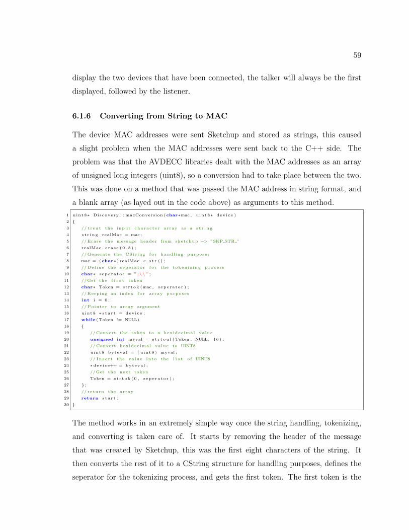
59
display the two devices that have been connected, the talker will always be the first
displayed, followed by the listener.
6.1.6 Converting from String to MAC
The device MAC addresses were sent Sketchup and stored as strings, this caused
a slight problem when the MAC addresses were sent back to the C++ side. The
problem was that the AVDECC libraries dealt with the MAC addresses as an array
of unsigned long integers (uint8), so a conversion had to take place between the two.
This was done on a method that was passed the MAC address in string format, and
a blank array (as layed out in the code above) as arguments to this method.
1 u int 8∗ Discovery : : macConversion ( char∗mac , u int 8∗ dev i ce )
2 {3 // t r e a t the input charac t e r array as a s t r i n g
4 s t r i n g realMac = mac ;
5 //Erase the message header from sketchup −> ”SKP STR ”
6 realMac . e ra s e ( 0 , 8 ) ;
7 //Generate the CString f o r handl ing purposes
8 mac = ( char∗) realMac . c s t r ( ) ;
9 //Def ine the s epe ra to r f o r the token i z i ng proce s s
10 char∗ s epe ra to r = ” :\\ ” ;
11 //Get the f i r s t token
12 char∗ Token = s t r t ok (mac , s epe ra to r ) ;
13 //Keeping an index f o r array purposes
14 int i = 0 ;
15 // Pointer to array argument
16 u int 8 ∗ s t a r t = dev i ce ;
17 while (Token != NULL)
18 {19 //Convert the token to a hex idec imal value
20 unsigned int myval = s t r t o u l (Token , NULL, 16 ) ;
21 //Convert hex idec imal value to UINT8
22 uint 8 byteva l = ( u int 8 ) myval ;
23 // I n s e r t the value in to the l i s t o f UINT8
24 ∗ dev i ce++ = byteva l ;
25 //Get the next token
26 Token = s t r t ok ( 0 , s epe ra to r ) ;
27 } ;28 // return the array
29 return s t a r t ;
30 }
The method works in an extremely simple way once the string handling, tokenizing,
and converting is taken care of. It starts by removing the header of the message
that was created by Sketchup, this was the first eight characters of the string. It
then converts the rest of it to a CString structure for handling purposes, defines the
seperator for the tokenizing process, and gets the first token. The first token is the

60
first two characters of the MAC address which are to be converted to hexadecimal
values. The conversion is then done within the loop and the list is updated with the
corresponding values. This is then continuously done until there are no remaining
tokens, which is when the address has been successfully converted.
6.1.7 Streaming Audio
1 void Discovery : : Stream ( uint 8 t a l k e r gu i d [ ] , u int 8 l i s t e n e r g u i d [ ] )
2 {3 AfxMessageBox ( ”Beginning stream” ) ;
4 /∗∗5 ∗ I n i t i a l i z e the ACMPCommandParams
6 ∗ IEEE 1722.1/ Draft 21 standard document , Page 271
7 ∗/8 avdecc acmp du acmp command params cmdParams ;
9 memcpy(cmdParams . t a l k e r gu id , t a l k e r gu id , s izeof ( cmdParams . t a l k e r gu i d ) ) ;
10 memcpy(cmdParams . l i s t e n e r g u i d , l i s t e n e r g u i d , s izeof ( cmdParams . l i s t e n e r g u i d ) ) ;
11 cmdParams . t a l k e r un i qu e i d = 0 ;
12 cmdParams . l i s t e n e r u n i q u e i d = 0 ;
13 cmdParams . connect ion count = 0 ;
14 cmdParams . f l a g s = 0 ;
15 // Set the command to connect
16 cmdParams . message type = AVDECCACMPDUMSGTYPECONNECTRXCOMMAND;
17 avdecc acmp controller sm doCommand(&acmp cntrl sm ,&cmdParams) ;
18 }
This is the method that creates the connection between two AVDECC entities. The
majority of this code was provided by Osedum Igumbor [32] however there was one
crucial change that had to be made for this method to fit into this project. The orig-
inal method statically defined the MAC addresses of the talker and listener entities
within its body. This had to be changed so the method would take the two arrays
of unsigned integers corresponding to the talker and listener, which were provided by
Sketchup, and make the connection between those two.
Disconnecting streams between devices followed the identical process with one change,
this was the command parameter shown in line 17 changing from the connect com-
mand to the disconnect command. The change is shown in the code listing below.
1 void Discovery : : DisconnectStreams ( u int 8 t a l k e r gu i d [ ] , u int 8 l i s t e n e r g u i d [ ] )
2 {3 // Def in ing command parameters ( omitted )
4 // . . .
5 //Changed command to d i s connect
6 cmdParams . message type = AVDECC ACMPDU MSG TYPE DISCONNECT RX COMMAND;
7 //Send the command
8 avdecc acmp controller sm doCommand(&acmp cntrl sm ,&cmdParams) ;
9 }

61
6.2 Ruby
A lot of the user interface code has been describe in Chapter 4 so this will not be
repeated in this section. This section describes the methods used in the interaction
between Visual C++ and Sketchup, as well as describes methods used in the device
management plugin that handles the devices.
6.2.1 Parsing the Messages from Visual C++
There are two different action messages that could possibly be received from the C++
side, creating a device, and requesting a stream. This was less than expected due to
the fact that all the implementation goals were not reached.
1 def s o c k e t l i s t e n e r (v )
2 codeArr = v . s p l i t ( ” ” ) #Sp l i t message on Underscore charac t e r
3 i f codeArr [ 0 ] == ”CPP” #Check C++ source
4 puts ”CPP SOURCE FOUND”
5 i f codeArr [ 1 ] == ”ENA” #Check dev i ce enumeration command
6 i f codeArr [ 2 ] == ”ATT” #Check that dev i ce i s Atterotech Board
7 puts ”ATTEROTECH BOARD FOUND, ID = ” + $numDvcs . t o s ( ) + ” , MAC = ” + codeArr [ 3 ]
8 addATT( codeArr [ 3 ] ) #Cal l add Atterotech Method
9 sendData ( ”SKP ACK ENA ATT ”+codeArr [ 3 ] ) #Send ACK message to C++
10 puts ”\n”
11 end
12 end
13
14 i f codeArr [ 1 ] == ”STR” #Check f o r streaming command
15 i f codeArr [ 2 ] == ”CON” #Check that connect ion i s being made
16 puts ”Creat ing Stream”
17 $streamReady = true #Allow a stream to be created
18 s t r eamSe l e c t i on
19
20 e l s i f codeArr [ 2 ] == ”DCN” #Check f o r d i s connec t ing command
21 puts ”Streams Disconnected ”
22 $streamReady = true #Allow a stream to be d i sconnected
23 s t r eamSe l e c t i on
24
25 end
26 end
27 else
28 puts ”Source unrecognized ”
29 end
30 end
The first line of this method splits the message on the underscore character into an
array. This is to simplify the identification of the commands as they can be extracted
from the array and compared directly to other strings. The comparison is then done
to ensure that the message received is actually from the C++ source, and the action
it requests. The first method is the device enumeration, this is the method for adding

62
an Atterotech board to the 3D environment. The actual adding of the board is done
in a method called ”addATT” which is called in this section of code - this method
takes the board’s MAC address as an argument.
The second half of this method deals with the streaming between devices. This plugin
contains a boolean variable called ”streamReady” which gets set to true on the recog-
nition of a streaming command∗. The streamSelection method is then called which
is responsible for the selection of the devices to be associated with the connecting or
disconnecting of audio streams.
6.2.2 Creating Atterotech Boards
1 def addATT( ipAddr )
2 #Check that the Atterotech board doesn ’ t ex i s t , so no dup l i c a t e s are c reated
3 loop = 0
4 while loop < $Dvcs . s i z e
5 i f ( $Dvcs [ loop ] ) [ 4 ..−1 ] == ipAddr
6 return
7 end
8 loop += 1
9 end
10 #Def in ing the model
11 model = Sketchup . act ive mode l
12 pant s de f = Sketchup . act ive mode l . d e f i n i t i o n s . load ( ”C:\\Program F i l e s ( x86 )\\Google\\Google
SketchUp 8\\Components\\Sound Control \\ATTBoard . skp” )
13 pan t s l o c a t i on = Geom : : Point 3d . new $ATTpos , 100 , 0
14 transform = Geom : : Transformation . new pan t s l o c a t i on
15 e n t i t i e s = Sketchup . act ive mode l . a c t i v e e n t i t i e s
16 in s tance = e n t i t i e s . add ins tance pants de f , transform
17 #Add the board to the l i s t o f dev i c e s
18 $Dvcs [ $numDvcs ] = ”ATT: ” + ipAddr
19 $numDvcs += 1
20 $ATTpos += 30
21 #Remove any ” n i l ” va lues from the l i s t
22 $Dvcs = $Dvcs . compact
23 end
This method takes in the MAC address of the board requested to enumerate. The
first section of this method is a ’for’ loop which goes through the devices list and
checks that the MAC address passed to this method is not already contained in the
model, therefore not allowing more than one device with the same address. This
method performs the same process described in Section 4.2.5 for adding the model
of the board to the 3D interface, the device is then added to the devices list as an
∗The significance of this variable will be discussed in Shapter 6.2.4
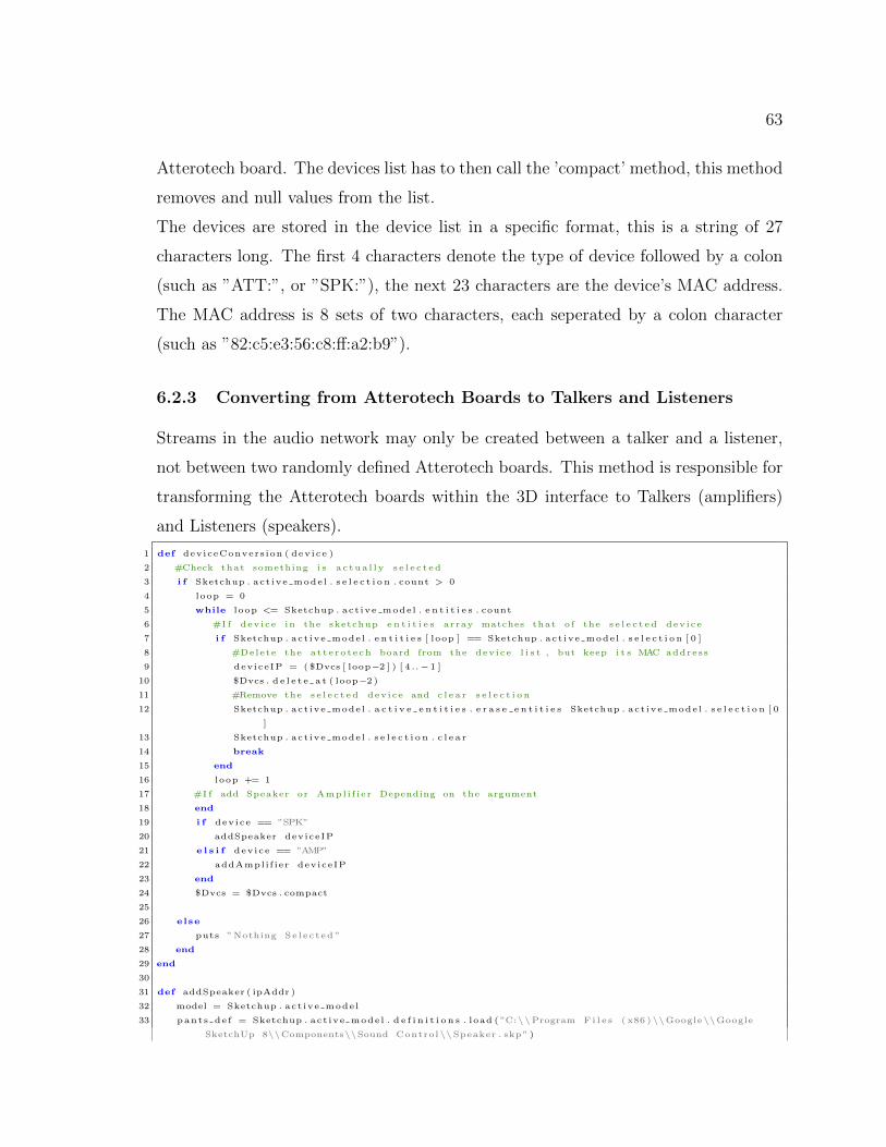
63
Atterotech board. The devices list has to then call the ’compact’ method, this method
removes and null values from the list.
The devices are stored in the device list in a specific format, this is a string of 27
characters long. The first 4 characters denote the type of device followed by a colon
(such as ”ATT:”, or ”SPK:”), the next 23 characters are the device’s MAC address.
The MAC address is 8 sets of two characters, each seperated by a colon character
(such as ”82:c5:e3:56:c8:ff:a2:b9”).
6.2.3 Converting from Atterotech Boards to Talkers and Listeners
Streams in the audio network may only be created between a talker and a listener,
not between two randomly defined Atterotech boards. This method is responsible for
transforming the Atterotech boards within the 3D interface to Talkers (amplifiers)
and Listeners (speakers).
1 def deviceConvers ion ( dev i ce )
2 #Check that something i s a c tua l l y s e l e c t e d
3 i f Sketchup . act ive mode l . s e l e c t i o n . count > 0
4 loop = 0
5 while loop <= Sketchup . act ive mode l . e n t i t i e s . count
6 #I f dev i ce in the sketchup e n t i t i e s array matches that o f the s e l e c t e d dev i ce
7 i f Sketchup . act ive mode l . e n t i t i e s [ loop ] == Sketchup . act ive mode l . s e l e c t i o n [ 0 ]
8 #Delete the a t t e r o t e ch board from the dev i ce l i s t , but keep i t s MAC address
9 deviceIP = ( $Dvcs [ loop−2 ] ) [ 4 ..−1 ]
10 $Dvcs . d e l e t e a t ( loop−2 )
11 #Remove the s e l e c t e d dev i ce and c l e a r s e l e c t i o n
12 Sketchup . act ive mode l . a c t i v e e n t i t i e s . e r a s e e n t i t i e s Sketchup . act ive mode l . s e l e c t i o n [ 0
]
13 Sketchup . act ive mode l . s e l e c t i o n . c l e a r
14 break
15 end
16 loop += 1
17 #I f add Speaker or Ampl i f i e r Depending on the argument
18 end
19 i f dev i ce == ”SPK”
20 addSpeaker deviceIP
21 e l s i f dev i ce == ”AMP”
22 addAmpl i f ier dev iceIP
23 end
24 $Dvcs = $Dvcs . compact
25
26 else
27 puts ”Nothing Se l e c t ed ”
28 end
29 end
30
31 def addSpeaker ( ipAddr )
32 model = Sketchup . act ive mode l
33 pant s de f = Sketchup . act ive mode l . d e f i n i t i o n s . load ( ”C:\\Program F i l e s ( x86 )\\Google\\Google
SketchUp 8\\Components\\Sound Control \\Speaker . skp” )

64
34
35 pan t s l o c a t i on = Geom : : Point 3d . new $spkrPos , 200 , 0
36 transform = Geom : : Transformation . new pan t s l o c a t i on
37 e n t i t i e s = Sketchup . act ive mode l . a c t i v e e n t i t i e s
38 in s tance = e n t i t i e s . add ins tance pants de f , transform
39
40 $Dvcs [ $numDvcs ] = ”SPK: ” + ipAddr
41 $numDvcs += 1
42 $spkrPos += 30
43 end
The ’deviceConversion’ method takes care of finding the selected device, extracting
the MAC address, and removing it from the model. This method then calls the
function to add a talker or a listener, depending on the argument. The argument
will either be ”SPK” or ”AMP” which is generated automatically on the button click
for initiating the conversion. Once the selected device has been removed from the
devices list, the ’addSpeaker’ or ’addAmplifier’ function is called, depending on what
the user has chosen to convert to. The ’addSpeaker’ method is shown above which
is almost identical to the method used to add Atterotech boards and Amplifiers, the
slight difference being the altering of the speaker position (line 42), the type of device
being added, and the component in the sound control directory (line 33).
6.2.4 Sending the Device MAC Addresses for Stream Request
When Sketchup receives the message from the socket requesting a stream talker and
listener, the user is then responsible for selecting the devices in the 3D environment.
The plugin then needs to extract the MAC addresses of the selected devices and write
them back to the socket in order for the stream to be created.
1 def s t r eamSe l e c t i on
2 #Check that exac t l y two dev i c e s have been s e l e c t e d and the program has been f l agged to stream
3 i f ( Sketchup . act ive mode l . s e l e c t i o n . count == 2 ) and ( $streamReady == true )
4 #Loop to f i nd the s e l e c t e d dev i c e s by comparing dev i ce ID ’ s
5 loop = 0
6 while loop <= Sketchup . act ive mode l . e n t i t i e s . count
7 i f Sketchup . act ive mode l . e n t i t i e s [ loop ] == Sketchup . act ive mode l . s e l e c t i o n [ 0 ]
8 dev i ce 1 = $Dvcs [ loop−2 ]
9 e l s i f Sketchup . act ive mode l . e n t i t i e s [ loop ] == Sketchup . act ive mode l . s e l e c t i o n [ 1 ]
10 dev i ce 2 = $Dvcs [ loop−2 ]
11 end
12 loop += 1
13 end
14 #Find which dev i ce i s the t a l k e r (AMP) and l i s t e n e r (SPK) and send them to C++
15 i f ( dev i ce 1 [ 0 . . 2 ] == ”AMP” ) and ( dev i ce 2 [ 0 . . 2 ] == ”SPK” )
16 sendData ”SKP STR ”+dev ice 1 [ 4 ..−1 ]
17 puts ”\n”

65
18 sendData ”SKP STR ”+dev ice 2 [ 4 ..−1 ]
19 puts ”\n”
20 e l s i f ( dev i ce 2 [ 0 . . 2 ] == ”AMP” ) and ( dev i ce 1 [ 0 . . 2 ] == ”SPK” )
21 sendData ”SKP STR ”+dev ice 2 [ 4 ..−1 ]
22 puts ”\n”
23 sendData ”SKP STR ”+dev ice 1 [ 4 ..−1 ]
24 puts ”\n”
25 Sketchup . act ive mode l . s e l e c t i o n . c l e a r
26 else
27 puts ” Inva l i d S e l e c t i o n ”
28 end
29 $streamReady = fa l se
30 else
31 puts ” Inva l i d S e l e c t i o n ”
32 end
33 end
This method is perhaps the most important part of the system as it allows the user
to select the devices from the 3D interface to create the audio stream. The first step
it takes is checking whether exactly two devices have been selected (one talker, and
one lister) and assigns these devices to variables named ’device1’ and ’device2’. At
this point it does not matter which one is the talker and which one is the listener.
The next step taken is checking which one is the talker and listener by extracting the
device type (first three characters) from each device in the devices list. Once this is
done, the method writes the SkAv message to the socket giving the correct format
for a streaming device, and the device’s respective MAC address. The C++ program
expects the talker’s MAC address to be sent first so working out which device is the
talker and which is the listener is crucial. The commands are then sent with the
talker being written to the socket first, and then the listener.
Throughout this method there are error checks to see whether the user has selected
more than one device, a device that has not been converted to an Atterotech board,
or two of the same devices. The result of this would be the Ruby console displaying
”Invalid Selection” and waiting for the user to make a proper selection. The client
mutex on the C++ side is locked so the user is forced to make a valid selection before
continuing to perform any further actions.

66
Chapter 7
Conclusion
7.1 Analysis of Goals
As indicated in chapter one, there were a total of five project goals:
• Discovering devices on a network and displaying them in the 3D environment
• Creating audio streams between devices
• Implement a sound control protocol to communicate directly with Sketchup
• Enable the user to control remote parameters
• Test the scalability of the system
The system was able to discover any audio devices on the network. Devices advertised
themselves on the network through the use of callbacks. The system stores any audio
device if it receives a callback from a device with a MAC address that is not already
contained in the devices list. The user is able to select the ”Discover Devices” button
from the Visual C++ user interface. This causes the device list to be sent to Sketchup,
which in turn displays the devices XMOS Atterotech boards in the 3D environment.
s A user can connect two audio devices and have them transmit and receive audio
streams. This is done by the user requesting to create a stream on the Visual C++
interface, which then sends the appropriate messages to Sketchup to let it know that
a stream connection is about to be made. The user then performs the connection
in the Sketchup environment. This was done successfully most of the time, however
on some occasions the AVDECC library would throw a ”stack corruption” error, but
would still not affect the functionality of the program if the error was ignored.
The communication between Sketchup and Visual C++ was done using a socket that

67
listened on the localhost (127.0.0.1) and used port 30456. Although the interaction
worked perfectly, the way that it had to be initiated caused some problems. When
the Visual C++ program wrote to the socket, Sketchup would read it automatically
and take the appropriate actions. This did not work as easily when Sketchup wrote
to the socket as Visual C++ needs a method that has to be called manually to read
the data from the socket. This method was then automatically called when any user
interaction could result in a response from Sketchup. The purpose of this method is
to lock a mutex, read the data from the socket, and then unlock the mutex. This
method would sometimes read the data and not process it, creating a problem that
the client mutex would still be locked. This was solved by having an option on the
Sketchup plugins menu that sent a further message, resulting in the mutex to be
locked and the socket cleared.
The secondary goal that could not be tested was the scalability of the system. This
goal has two different interpretations, ideally both were to be tested, however this
was not plausible at the time due to a limited number of devices. The first is testing
the scalability of the system in terms of the number of devices, the second is testing
the scalability in terms of the distance distribution of the devices. The testing for
this would be the quality of the audio over the large scale distribution, as well as the
quality of service in delivering the audio to its destinations. The scalability of devices
would most likely work as the devices would be in the same AVB subnet [15].
The secondary goal that was not able to be implemented was the remote control
of device parameters. To successfully achieve this, the AVDECC Enumeration and
Control protocol would have to be implemented. This protocol had not been ported
for Windows implementation within the time frame, so could not be included in the
project.
7.2 Future work
This section suggests future work and possible extensions for anybody that wishes to
continue with the development of the system.
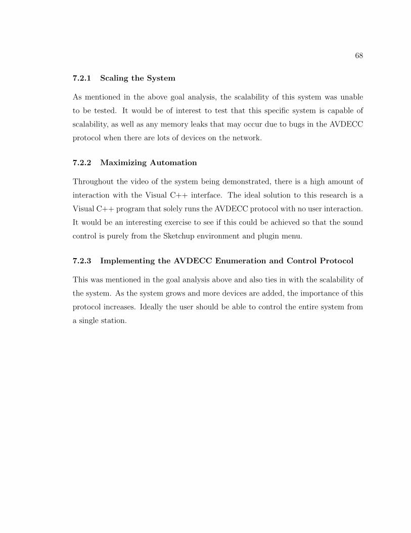
68
7.2.1 Scaling the System
As mentioned in the above goal analysis, the scalability of this system was unable
to be tested. It would be of interest to test that this specific system is capable of
scalability, as well as any memory leaks that may occur due to bugs in the AVDECC
protocol when there are lots of devices on the network.
7.2.2 Maximizing Automation
Throughout the video of the system being demonstrated, there is a high amount of
interaction with the Visual C++ interface. The ideal solution to this research is a
Visual C++ program that solely runs the AVDECC protocol with no user interaction.
It would be an interesting exercise to see if this could be achieved so that the sound
control is purely from the Sketchup environment and plugin menu.
7.2.3 Implementing the AVDECC Enumeration and Control Protocol
This was mentioned in the goal analysis above and also ties in with the scalability of
the system. As the system grows and more devices are added, the importance of this
protocol increases. Ideally the user should be able to control the entire system from
a single station.

69
Appendix
Sequence Diagrams
Figure 7.1 : Sketchup Sequence 1 - Moving a device

70
Figure 7.2 : Sketchup Sequence 2 - Moving a camera using plugins
Figure 7.3 : Sketchup Sequence 3 - Moving a camera using the tools

71
Figure 7.4 : Sketchup Sequence 4 - Making a stream connection
Figure 7.5 : Sketchup Sequence 5 - Controlling a device
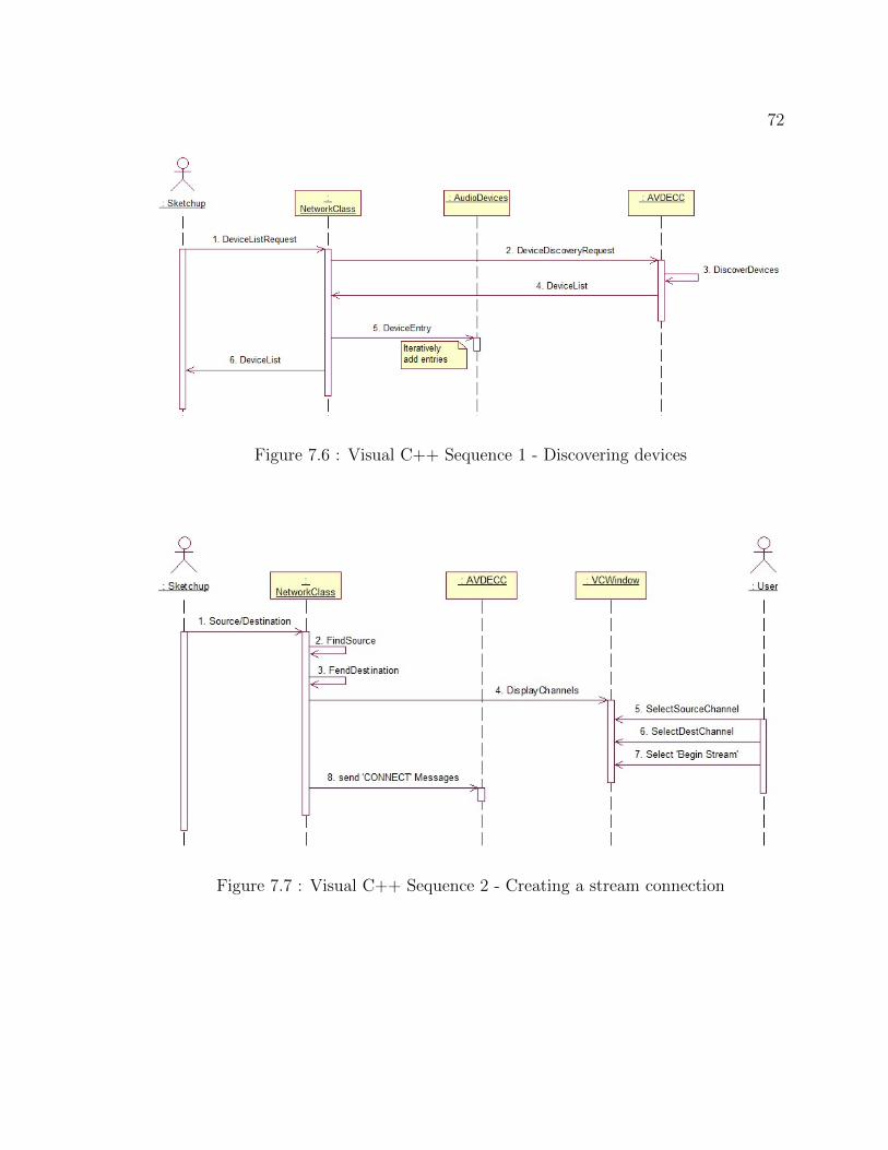
72
Figure 7.6 : Visual C++ Sequence 1 - Discovering devices
Figure 7.7 : Visual C++ Sequence 2 - Creating a stream connection

73
Figure 7.8 : Visual C++ Sequence 3 - Controlling a device

74
Bibliography
[1] About Biamp. Online. Available from: http://www.biamp.com/about.
[2] About Ruby. Online. Available from: http://www.ruby-lang.org/en/about/.
[3] Google Sketchup Ruby API. Online. Available from: https://developers.
google.com/sketchup/.
[4] Google Sketchup Ruby API - Cameras. Online. Available from: https://
developers.google.com/sketchup/docs/ourdoc/camera.
[5] Google Sketchup Ruby API - Entities. Online. Available from: https:
//developers.google.com/sketchup/docs/ourdoc/entities.
[6] Google Sketchup Ruby API - Entity. Online. Available from: https://
developers.google.com/sketchup/docs/ourdoc/entity#entityID.
[7] Google Sketchup Ruby API - Geom. Online. Available from: https://
developers.google.com/sketchup/docs/ourdoc/geom.
[8] Google Sketchup Ruby API - Menu. Online. Available from: https://
developers.google.com/sketchup/docs/ourdoc/menu#add_submenu.
[9] Google Sketchup Ruby API - Point3D. Online. Available from: https:
//developers.google.com/sketchup/docs/ourdoc/point3d.
[10] Google Sketchup Ruby API - Transformation. Online. Available from:
https://developers.google.com/sketchup/docs/ourdoc/transformation#
translation.
[11] Google Sketchup Ruby API - UI. Online. Available from: https://developers.
google.com/sketchup/docs/ourdoc/ui.

75
[12] HiQnet Protocol and Harman System Architect. Online. Available
from: http://www.akg.com/site/products/powerslave,id,948,pid,948,
nodded,2,_language,EN.html.
[13] Rational Rose Modeler. Online. Available from: http://www-01.ibm.com/
software/awdtools/developer/rose/modeler/.
[14] Tesira. Online. Available from: http://www.biamp.com/products/tesira/
index.aspx.
[15] Avb 802.1 priority encapsulation. Online, June 2007.
[16] About London Architect. Online, 2010. Available from: http://www.bssaudio.
com/LA_Features.php.
[17] What is System Architect? Online, 2010. Available from: http://hiqnet.
harmanpro.com/about/.
[18] Sketchup Tools. Online, February 2011. Available from: http://support.
google.com/sketchup/bin/answer.py?hl=en&answer=73815.
[19] Draft standard for standard device discovery, connection management and con-
trol protocol for ieee 1722 based devices - draft d19. Online, April 2012.
[20] Seismic Audio. Online, November 2012. Available from: http:
//www.seismicaudiospeakers.com/32-Channel-Splitter-Snake-p/
satss-32x1530.htm.
[21] UNOS Creator. Online, 2012. Available from: http://www.unosnet.com/
unosnet/index.php/unos-core.html.
[22] Dibley, J. Audio networks, March-April 2012.
[23] Foltz, J. Class: SKSocket. Online, May 2012. Available from:
http://rubydoc.info/github/jimfoltz/SketchUp-Ruby-API-Doc/master/
SKSocket.

76
[24] Foss, R. XFN Application Programming Interface. Universal Media Access
Networks, November 2009.
[25] Foss, R. UNOS Creator User Manual. UMAN, February 2011.
[26] Foulkes, P. An investigation into the control of audio streaming across net-
works having diverse quality of service mechanisms. PhD thesis, Rhodes, Septem-
ber 2011.
[27] Harman. HIQNet System Architect 2 Workflow Overview.
[28] Harman. HiQnet Third Party Programmer Documentation. Harman, December
2010.
[29] Harman. HiQNet System Architect. Online, 2012. Available from: http:
//hiqnet.harmanpro.com/general/system_architect.
[30] Haw, S. The x170 protocol as a vehicle for 3d sound control. Thesis, November
2011.
[31] Hilbert, M., and Lpez, P. The worlds technological capacity to store, com-
municate, and compute information. Online Journam, February 2011.
[32] Igumbor, O. libavdecc software library. Tech. rep., Rhodes University, 2012.
[33] Kulandai, J. Association, Aggregation, Composition, Abstraction, General-
ization, Realization, Dependency. Online, June 2010. Available from: http:
//javapapers.com/oops/.
[34] Kurose, J., and Ross, K. Computer Networking, vol. 5. Pearson, 2010.
[35] Lininger, S. Inserting an external Sketchup Component. Online,
March 2008. Available from: http://sketchupapi.blogspot.com/2008/03/
inserting-external-sketchup-component.html.
[36] Otten, F. Overview of Sound System Control and X-170. PhD thesis, Rhodes,
2012.