Embed Size (px)
Citation preview

Controlling a virtual rover using AutoFOCUS3
Levi Lucio, Sudeep Kanav, Andreas Bayha, and Johannes Eder
fortiss GmbHGuerickestraße 2580805 Munchen
{lucio,kanav,bayha,eder}@fortiss.org
Abstract. AUTOFOCUS3 (AF3) is a mature model-driven engineering envi-ronment for developing software for embedded systems. For the past 20 years,several versions of AF3 have served as a platform for experimenting with cuttingedge research ideas in Model-Driven Development. AF3 is a tool that fully en-compasses the software lifecycle, from requirements, to architecture, simulation,deployment, code generation and verification. In this article we describe how weused an existing model of a complex controller for a real-life miniature vehicleand have downsized and adapted it to control a rover in a virtual environment.The model we present here automates the maneuvering of a rover to follow an-other leader rover in a virtual environment, while keeping a safe distance to it.The controller operates by adapting the rover’s speed and steering according tothe position and movements of the leader. The results we present in this articleillustrate the whole development cycle of an embedded system using AF3, fromthe development of the model down to deployment to a specific platform as wellas code generation and connecting to the hardware.
Keywords: Modelling Environment · Embedded Systems · Deployment · CodeGeneration · Controller.
1 Introduction
AUTOFOCUS3 is a model-based development (MBD) environment for embedded sys-tems, based on the Focus theory [9]. Focus is a framework encompassing compu-tations supported by the notion of streams (“in particular untimed, timed and time-synchronous streams” [16]). The current version of AF3 follows a string of earlierprototypes [4, 16] started in 1996 [17]. Existing literature on AF3 reports on particularaspects of the tool [5,10–12,20,24,25], or on its application in the context of industrialcase studies [4, 6, 7, 13–15]. More information about current state of the AF3-relatedresearch can be found in the official site of the tool1. AF3 can be freely downloadedand is open-source.
AF3’s goal is to demonstrate the feasibility and applicability of MBD tooling ap-proaches. The idea behind AF3 embraces seamless integration of all models throughoutthe development process, encompassing requirements engineering on initial stage, sys-tem modeling at a high level of abstraction, deployment and model simulation. AF3
1 https://af3.fortiss.org/
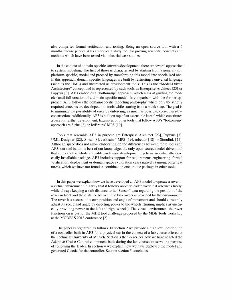
also comprises formal verification and testing. Being an open source tool with a 6months release period, AF3 embodies a study tool for proving scientific concepts andmethods which have been tested via industrial case studies.
In the context of domain-specific software development, there are several approachesto system modeling. The first of those is characterized by starting from a general (nonplatform-specific) model and proceed by transforming this model into specialized one.In this approach, domain specific languages are built by restricting a universal language(such as the UML) and incarnated as development tools. This is the “Model-DrivenArchitecture” concept and is represented by such tools as Enterprise Architect [23] orPapyrus [3]. AF3 embodies a “bottom-up” approach, which aims at guiding the mod-eler until full creation of a domain-specific model. In comparison with the former ap-proach, AF3 follows the domain-specific modeling philosophy, where only the strictlyrequired concepts are developed into tools while starting from a blank slate. The goal isto minimize the possibility of error by enforcing, as much as possible, correctness-by-construction. Additionally, AF3 is built on top of an extensible kernel which constitutesa base for further development. Examples of other tools that follow AF3’s “bottom-up”approach are Sirius [8] or JetBrains’ MPS [19].
Tools that resemble AF3 in purpose are Enterprise Architect [23], Papyrus [3],UML Designer [22], Sirius [8], JetBrains’ MPS [19], mbeddr [18] or Simulink [21].Although space does not allow elaborating on the differences between these tools andAF3, our tool is, to the best of our knowledge, the only open-source model-driven toolthat supports the whole embedded-software development cycle in an out-of-the-box,easily installable package. AF3 includes support for requirements engineering, formalverification, deployment or domain space exploration cases natively (among other fea-tures), which we have not found in combined in one unique package in other tools.
In this paper we explain how we have developed an AF3 model to operate a rover ina virtual environment in a way that it follows another leader rover that advances freely,while always keeping a safe distance to it. “Sensor” data regarding the position of therover in front and the distance between the two rovers is provided by the environment.The rover has access to its own position and angle of movement and should constantlyadjust its speed and angle by directing power to the wheels (turning implies asymetri-cally providing power to the left and right wheels). The virtual environment the roverfunctions on is part of the MDE tool challenge proposed by the MDE Tools workshopat the MODELS 2018 conference [2].
The paper is organized as follows. In section 2 we provide a high level descriptionof a controller built in AF3 for a physical car in the context of a lab course offered atthe Technical University of Munich. Section 3 then describes how we have adapted theAdaptive Cruise Control component built during the lab courses to serve the purposeof following the leader. In section 4 we explain how we have deployed the model andgenerated C code for the controller. Section section 5 concludes.

2 Controlling a physical vehicle with AUTOFOCUS3
The model that we developed for the MDE tool challenge is based on a larger model,that was originally created in the context of a lab course at Technical University Mu-nich. Two subsequent courses involving 10 students built not only the logical model forthe vehicle, but also the hardware platform of a car in a scale of 1:10. An importantrequirement for this vehicle was a high level of realism. Accordingly, a professionalplatform with a realistic Ackermann steering and electrical all wheel drive was chosenand configured in such a way that the driving dynamics correspond to a realistic car. Apicture of the vehicle is shown in Figure 1.
Fig. 1. A Physical Rover used for a lab course at the Technical University of Munich
The model that the students developed in the first lab course implemented basicdriving functionalities such as steering, braking, accelerating, gear shifting and differ-ent drive modes, as well as two driver assistance functions for emergency braking andadaptive cruise control. The second lab course extended this outcome with lane keep-ing as well as vehicle2vehicle communication and platooning. Our main interest in thedevelopment of such a vehicle was to show the applicability of model-based develop-ment by using our tool AUTOFOCUS3 on the one hand, and on the other hand to comeup with a software architecture for future (semi-) autonomous cars. The general ques-tion we addressed was how (semi-) autonomous functionality can be integrated into a

software architecture of a car, using a model-based approach. The current state of thearchitecture is shown in Figure 2 and is given as a means to illustrate the complexity ofthe model of the controller developed by the students.
For the MDE tool challenge we used the Adaptive Cruise Control (ACC) part ofthe model, highlighted in Figure 2. Because of the component based approach of AF3,we were able to reuse the component which realized this function and adapt it to thechallenge by developing against the component’s interface. Although we kept that partof the functionality that adapts the distance to the leader rover, we had to incorporate inthe model new capabilities to allow automatic steering in order to implement the “followthe leader” requirement. Naturally, we also had to adapt the inputs and the outputs ofthe component to the data provided and expected by the virtual environment.
3 Controlling the virtual rover
In Figure 3 we depict the top-level model of the controller for the follower vehicle. Thecontroller is meant to operate in a loop by reading the distance to the leader rover, theGPS coordinates of the leader (LeaderPosition) and the rover’s own (RoverPosition)GPS coordinates as well as its own orientation with respect to the north (RoverAngle).Note that the inputs to the model appear in Figure 3 as small black circles, while the out-puts have the same shape but are white. The power provided to the wheels is constantlyupdated to reflect the changes in the input values to the controller.
The controller for the virtual rover is composed by three AF3 components, as ex-plained in the next sections.
3.1 Component StraightPower
The StraightPower component is responsible for calculating the required forward powerbased on the distance to the leader.
This component is composed of two components as shown in Figure 4. The com-ponent CalculateDistanceError calculates the error with respect to the ideal distancewith the leader. For the proposed challenge, the follower was required to remain in thedistance range between 12 and 15 from the leader. We have thus taken the ideal distanceas the average of these two values, i.e. 13.5. This is a constant and can be easily changedto allow for different ranges.
We then use this error and feed it to a PID controller for calculating the power to bedirected forward. The general equation for a PID controller is:
u = KP e+KII +KDD (1)
, where KP ,KI and KD are the parameters of the controller, e is the error with thedesired value, I is the integral - summation of the previous errors, and D the differential- difference with the last error.
For calculating the forward power we have used the following constant values:KP = 5, KI = 1.5, KD = 30.

Fig. 2. The AF3 Model developed by the Students to Control a Physical Vehicle

Fig. 3. The controller for the Virtual Rover
Fig. 4. Subcomponents implementing the StraightAcceleration component.
3.2 Component RotationalDifferential
The rover turns when the left and right wheels rotate at different speeds. The magnitudeof the difference is proportional to the turning angle.
When the leader turns the follower also has to turn in order to follow the leader.In order to achieve this the RotationalDifferential component calculates the requireddifference between the power applied to the right and the left wheel to turn the rover toprovide the correct turning angle.
The component bearingAngle calculates the bearing of the leader with respect tonorth when seen from the follower. This calculation uses the GPS positions of the fol-lower and the leader. We then calculate the angleError i.e., the difference between theorientation of the follower (with respect to north) and the bearing angle. This angleErroris then passed onto another PID controller in order to calculate the required differencein power sent to the rover’s right and left wheels. The sign of this value decides thedirection of the turning.
The constants used of the PID controller (equation 1) for calculating the rotationaldifferential are: KP = 2, KI = 0.75, KD = 10.
3.3 Component CalculateFinalPower
The CalculateFinalPower component takes the forward power and rotational differ-ential, and outputs the final power to apply to the right and left wheels. In addition tocalculating the values for the right and left power, the component also normalizes theamount of power provided in case the calculated value exceeds the maximum.
The environment of the rover challenge proposed by the MDETools workshop pro-vides at the end of a run of the system, which lasts one minute, the percentage of time

Fig. 5. Subcomponents implementing the RotationalDifferential component.
during which the rover was within the expected distance limits. The system we devel-oped consistently stays within these limits over 70% of the runs we have attempted.Although we have not tuned the values of the PID controller further, we believe evenbetter results could be achieved. The AF3 models we have used for the challenge canbe downloaded at [1]. For readers interested in further experimentation, instructionsaccompanying the model provide the steps on how to install and deploy the software.
4 Deployment and code generation
After the model is built, it needs to be deployed on an architecture. For the real rovermentioned in section 2 the architecture is a Raspberry Pi that can connect to the sensorsand actuators of the device.
The virtual rover simulation environment used in the context of this article commu-nicates using TCP ports. Additionally, the signals flowing from the virtual environmentand back are different from the ones for the real rover. For instance, the real rover ac-cepts target speed as input and the hardware of the rover itself controls engine power(using an embedded PID controller) in order to attain such a speed and maintain it. Thevirtual rover expects that power to the wheels is provided as a means to attain a certainspeed.
AF3 provides a generic, non-device specific architecture for deployment, as shownin Figure 6. Additionally, the ports of the ECU need to be mapped to the logical portsof the controller of the model we have defined in section 3, as depicted in figure 7.
Deploying onto an architecture provides the skeleton of an interface that declaresthe signatures of the methods used by the controller logic to communicate with thedevice underneath. When the architecture is fully defined, the code with for gluingwith the device can also be automatically generated. For our work we have deployedonto a generic architecture as a means to automatically generate the structure of ourcontroller’s communication infrastructure as C2 code. The logic corresponding to themodel we have presented in section 2 is also generated as C code and is meant to run ina loop with the controlled device, in this case the virtual rover.
The C code that is generated for the generic architecture only provides the interfacefor the functions that read the sensors and send commands on the actuators of the virtual
2 Besides C, AF3 also allows the generating JAVA code.

Fig. 6. A Generic ECU for the Virtual Rover Controller
Fig. 7. Deploying the Logical Ports onto the ECU ports
environment. Because of that, a manual step of coding such methods and connecting thecontroller with the virtual environment via TCP was additionally necessary to connectthe controller to the rover and to finalize the deployment of the model onto the hardware.
5 Conclusion
We have presented in this article the lifecycle of the development of a controller fora virtual rover, based on a controller for a real vehicle developed at lab courses givenby us. Our experience points to the fact that AF3 is a sufficiently mature environmentfor developing embedded systems, in particular controllers. The facilities for generatingcode for a specific platform (in our case a generic one) make life for the developer ofembedded code simple, as the communication infrastructure with the underlying hard-ware can be fully automated. We have observed this advantage when we, in the courseof the lab courses, deployed the code generated from models directly to Raspberry Pis,without any need for further customization. Additionally, the modularity enforced by

AF3 makes it easy to reuse parts of projects. We found that the copy/paste facilities ofAF3 are very helpful in that respect.
We have certainly encountered editing issues with AF3’s editor while building themodel for the challenge, but they were minor and the modelling experience was veryslighted affected by them. The calibration of controllers such as the one we presentin this paper also poses a problem, as it is mostly only possible once the hardware isin the loop with the generated code. AF3 does not provide a basic infrastructure forcalibration (although a prototypical version of such an infrastructure does exist). Inpractice, we have observed that a significant amount of time still needs to be devoted tomaking sure the parameters of the controller are well configured.
References
1. AF3 model used in the MDETools 2018 challenge. http://download.fortiss.org/public/MDETools2018/model-and-instructions_AF3.zip.
2. MDETools Workshop Website. https://mdetools.github.io/mdetools18/,2018.
3. Papyrus user guide.The Eclipse Foundation. https://wiki.eclipse.org/Papyrus_User_Guide, 2018.
4. V. Aravantinos, S. Voss, S. Teufl, F. Holzl, and B. Schatz. AutoFOCUS 3: Tooling conceptsfor seamless, model-based development of embedded systems. In Proc. 8th Int. MODELSWorkshop Model-based Archit. Cyber-physical Embed. Syst. (ACES-MB ’15), pages 19–26,2015.
5. S. Barner, A. Diewald, F. Eizaguirre, A. Vasilevskiy, and F. Chauvel. Building product-lines of mixed-criticality systems. In Proc. Forum Specif. Des. Lang. (FDL 2016), Bremen,Germany, Sept. 2016. IEEE.
6. S. Barner, A. Diewald, J. Migge, A. Syed, G. Fohler, M. Faugere, and D. Gracia Perez.DREAMS toolchain: Model-driven engineering of mixed-criticality systems. In Proc.ACM/IEEE 20th Int.Conf. Model Driven Eng. Lang. Syst. (MODELS ’17), pages 259–269.IEEE, 2017.
7. W. Bohm, M. Junker, A. Vogelsang, S. Teufl, R. Pinger, and K. Rahn. A formal systemsengineering approach in practice: An experience report. In Proc. 1st Int. Workshop SoftwareEngineering Research and Industrial Practices, pages 34–41, New York, NY, USA, 2014.ACM.
8. S. Bonnet and C. Brun. Sirius: Your custom modeling environment made easy, at last!.EclipseCon. http://www.eclipse.org/sirius/doc/, 2013.
9. M. Broy and K. Stølen. Specification and Development of Interactive Systems: Focus onStreams, Interfaces, and Refinement. Springer, 2001.
10. A. Campetelli, F. Holz, and P. Neubeck. User-friendly model checking integration in model-based development. In Proc. 24th Int. Conf. Comput. Appl. Ind. Eng. (CAINE 2011). ISCA,2011.
11. C. Carlan, S. Barner, A. Diewald, A. Tsalidis, and S. Voss. ExplicitCase: Integrated model-based development of system and safety cases. In Proc. SAFECOMP Workshops (ASSURE’17), pages 52 – 63. Springer, 2017.
12. A. Diewald, S. Voss, and S. Barner. A lightweight design space exploration and optimizationlanguage. In Proc. 19th Int. Workshop Softw. Compil. Embed. Syst. (SCOPES ’16), pages190–193. ACM, 2016.

13. J. Eder, S. Zverlov, S. Voss, M. Khalil, and A. Ipatiov. Bringing DSE to life: exploring thedesign space of an industrial automotive use case. In Proc. ACM/IEEE 20th Int.Conf. ModelDriven Eng. Lang. Syst. (MODELS ’17), pages 270–280. IEEE, Sept. 2017.
14. M. Feilkas, F. a. P. F. Holzl, S. Rittmann, B. Schatz, W. Schwitzer, W. Sitou, M. Spichkova,and D. Trachtenherz. A refined top- down methodology for the development of automo-tive software systems: The keylessentry system case study. Technical Report TUM-I1103,Technische Universitat Munchen, 2011.
15. M. Feilkas, A. Fleischmann, F. Holzl, C. Pfaller, K. Scheidemann, M. Spichkova, and D. Tra-chtenherz. A top-down methodology for the development of automotive software. TechnicalReport TUM-I0902, Technische Universitat Munchen, 2009.
16. F. Holzl and M. Feilkas. AutoFOCUS 3: A scientific tool prototype for model-based devel-opment of component-based, reactive, distributed systems. In Proc. 2007 Int. Dagstuhl Conf.Model-based Eng. Embed. Real-time Syst. (MBEERTS’07), pages 317–322. Springer, 2010.
17. F. Huber, B. Schatz, A. Schmidt, and K. Spies. Autofocus – a tool for distributed systemsspecification. In Proc. Formal Tech. Real-Time Fault-Tolerant Syst. (FTRTFT’96), pages467–470. Springer, 1996.
18. itemis. mbeddr 2017.2.0. http://mbeddr.com/, 2017.19. JetBrains. Meta Programming Systems. MPS 2017. Tutorials Formatted by Space2Latex
from the MPS wiki 2017-08-02. http://www.eclipse.org/sirius/doc/, 2017.20. L. Lucio, S. bin Abid, S. Rahman, V. Aravantinos, R. Kuestner, and E. Harwardt. Process-
aware model-driven development environments. In Proc. of FlexMDE 2017, co-located withMODELS 2017, volume 2019, pages 405–411. CEUR-WS.org, 2017.
21. MathWorks. Simulink 9,0. https://www.mathworks.com, 2017.22. Obeo. UML Designer.Getting started. http://www.umldesigner.org/
tutorials/tuto-getting-started.htm, 2018.23. SparxSystems. Enterprise architect 13 Reviewer’s Guide, 2016.24. S. Teufl, D. Mou, and D. Ratiu. MIRA: A tooling-framework to experiment with model-
based requirements engineering. In Proc. 21st Int. Conf. Requirements Engineering (RE’13). IEEE, 2013.
25. S. Voss, J. Eder, and F. Holzl. Design space exploration and its visualization in AutoFO-CUS 3. In Gemeinsamer Tagungsband der Workshops der Tagung Software Engineering2014, pages 57–66. RWTH, 2014.