Embed Size (px)
Citation preview

Flanged Floating Ball Valve
PRINTED IN U.S.A. - 2016 ©7603 Bluff Point Drive - Houston, TX 77086 - (281) 880.8560
TO MARK PROGRESS
C A T A L O G 4 2 1
Controlled Quality CORROSION RESISTANT
7603 Bluff Point Dr.Houston, TX 77086281-880-8560
2
TITLE PAGE .......................................................................................................1TABLE OF CONTENTS ......................................................................................2LADISH VALVES – A HERITAGE BRAND ..........................................................3LADISH PRODUCT LINE OVERVIEW ................................................................4LADISH SERVICES, WHY WE'RE DIFFERENT .....................................................5CATALOG 421 – FLANGED FLOATING BALL VALVE ......................................6OVERVIEW – FLANGED QUARTER-TURN PRODUCTS .....................................7HOW TO ORDER ..............................................................................................8 PRODUCT RANGE AND DESIGN STANDARDS ...............................................9STANDARD DESIGN FEATURES .......................................................................10FIRE SAFE DESIGN FEATURES ..........................................................................11MODEL P8/R8 TWO PIECE FULL BORE DESIGN FEATURES ..............................12MODEL P8/R8 TWO PIECE FULL BORE DIMENSIONAL DATA .........................13MODEL P7/R7 TWO PIECE STANDARD BORE DESIGN FEATURES ..................14MODEL P7/R7 TWO PIECE STANDARD BORE DIMENSIONAL DATA ..............15MODEL P9/R9 UNI-BODY STANDARD BORE DESIGN FEATURES ...................16MODEL P9/R9 UNI-BODY STANDARD BORE DIMENSIONAL DATA ...............17MODEL P2 TWO PIECE BAR STCK FULL BORE DESIGN FEATURES ..................18MODEL P2 TWO PIECE BAR STCK FULL BORE DIMENSIONAL DATA ..............19PARTS & MATERIALS STEM PACKING DESIGN (P7,P8,P9) .............................20,21PARTS & MATERIALS O-RING DESIGN (R7,R8,R9) ..........................................22,23PARTS & MATERIALS BAR STOCK DESIGN (P2) ..............................................24MAINTENANCE & REPAIR KITS GUIDANCE ....................................................25FLANGED FLOATING BALL VALVES – ENGINEERING CAPABILITIES .............26TECHNICAL DATA
PRESSURE & TEMPERATURE RATINGS .........................................................27ACTUATOR MOUNTING DATA ...................................................................28FLOW COEFFICIENTS ..................................................................................29
TABLE OF CONTENTS
Controlled Quality FLANGED FLOATING BALL VALVE 3
Herman W. Ladish was born in Milwaukee, Wisconsin in 1880 and began his career in the bustling malting industry at the age of 16. Herman quickly established himself in the business, climbing the corporate ladder and assuming the role of superintendent at The American Malting Company. Ladish folklore has it that Herman’s interest in metalworking was born from a problematic crankshaft that consistently halted production. Herman’s search for an alternative manufacturing method led him to metal forging and the birth of a metal working conglomerate of
forgings, flanges, fittings, and industrial valves was born.
Today, Ladish Valves is proud to have a history dating back to 1961 in Cynthiana, Kentucky. After experiencing a crippling flood of the Ohio River and several changes in ownership, Ladish Valves moved its headquarters to Houston, Texas in 2007.
With a foundation of more than 60 years of industrial valve production, Ladish Valves continues to be the industry benchmark for stainless steel and high nickel alloy industrial valves. The Ladish Valves trademark symbolizes a reputation that is emblematic of the highest quality standards, unmatched design, and metalworking craftsmanship. Our history is important to us and we pay homage to it daily.
The Ladish Valves product line is specifically designed and manufactured to meet the stringent demands of the most corrosive service environments and high temperature applications. Our product is produced under rigorous metallurgical and manufacturing controls that assure a consistent, high degree of performance and dependability. The quality of the material we receive is critical to the quality of our product. With domestic source foundries and strictly monitored international vendors, Ladish Valves is relentless about the quality of materials sourced from its vendor community.
What It Means "To Mark Progress"
Ladish Valves is a responsive company that prides itself in being "local" with an exhaustive commitment to our customers and our product. This means that no matter where you are, our team in Houston will provide a customized, clear response in a timely manner. We pride ourselves in serving our customers and taking on the challenges of unconventional projects.
Herman W. Ladish, Founder
OUR HISTORY

7603 Bluff Point Dr.Houston, TX 77086281-880-8560
4
CAST FORGED BAR STOCK
THREADED ENDS SOCKET ENDS
FLANGED ENDS BUTTWELD ENDS FLAT FACE ENDS
RISING HANDWHEEL
NON-RISING HANDWHEEL
SOLID WEDGE DISCFLEX WEDGE DISCSPLIT WEDGE DISC
PLUG DISCTEFLON DISC
1/2 THRU 36” CL150 THROUGH CL2500
CARBON STEEL STAINLESS STEEL
ALLOY 20 DUPLEX HIGH NICKEL ALLOY
TITANIUM ZIRCONIUM
ALSO AVAILABLE:
CAST STEELCATALOG 821
CRYOGENICCATALOG 321
FORGED STEELCATALOG 221
CAST, TWO-PIECE FULL / STANDARD BORE
PACKING / O-RING STEM DESIGN
BAR-STOCK, TWO-PIECE FULL BORE
PACKING STEM DESIGN
CAST, UNI-BODY STANDARD BORE
PACKING / O-RING STEM DESIGN
Ladish Complete Line of Products Manufactured to the ultimate in quality standards
CATALOG 421 FLANGED FLOATING BALL VALVE
GATE GLOBE CHECK BALL PRESSURE SEAL
BELLOW SEAL CRYOGENIC
Controlled Quality FLANGED FLOATING BALL VALVE 5
CATALOG 321
Ladish Services & Why We're Different One-stop Manufacturing, Controlled Quality
Ladish Valves is a premier manufacturer of multi-turn and quarter-turn valves. Our valves are widely used in the chemical and petrochemical markets spanning from upstream extraction through midstream transportation and downstream processing. Ladish has a long history of supplying products to these markets, in addition to the power and pulp & paper industries.
Ladish has a full complement of value-added services to address the many challenges that often delay projects. Our team specializes in quick turnaround deliveries (even on challenging orders), with the confidence of controlled quality through in-house design and manufacturing.
Ladish is local. Our manufacturing facility is located in Houston, Texas, giving us the flexibility to design, machine, assemble, test, verify, and expedite our customers' orders, setting us apart from everyone else. Our other differentiators include:
• One of the largest (stocked) stainless and exotic alloy inventories in the U.S.• In-house machining: Cryo extensions, end connections, modifications, etc.• Same-day deliveries available • Custom valve solutions utilizing Ladish engineering & design teams• Fully compliant clean room (oxygen, chlorine, hydrogen peroxide and others)• Extensive in-house NDE capabilities
A Step Above the Competition...and Here's Why
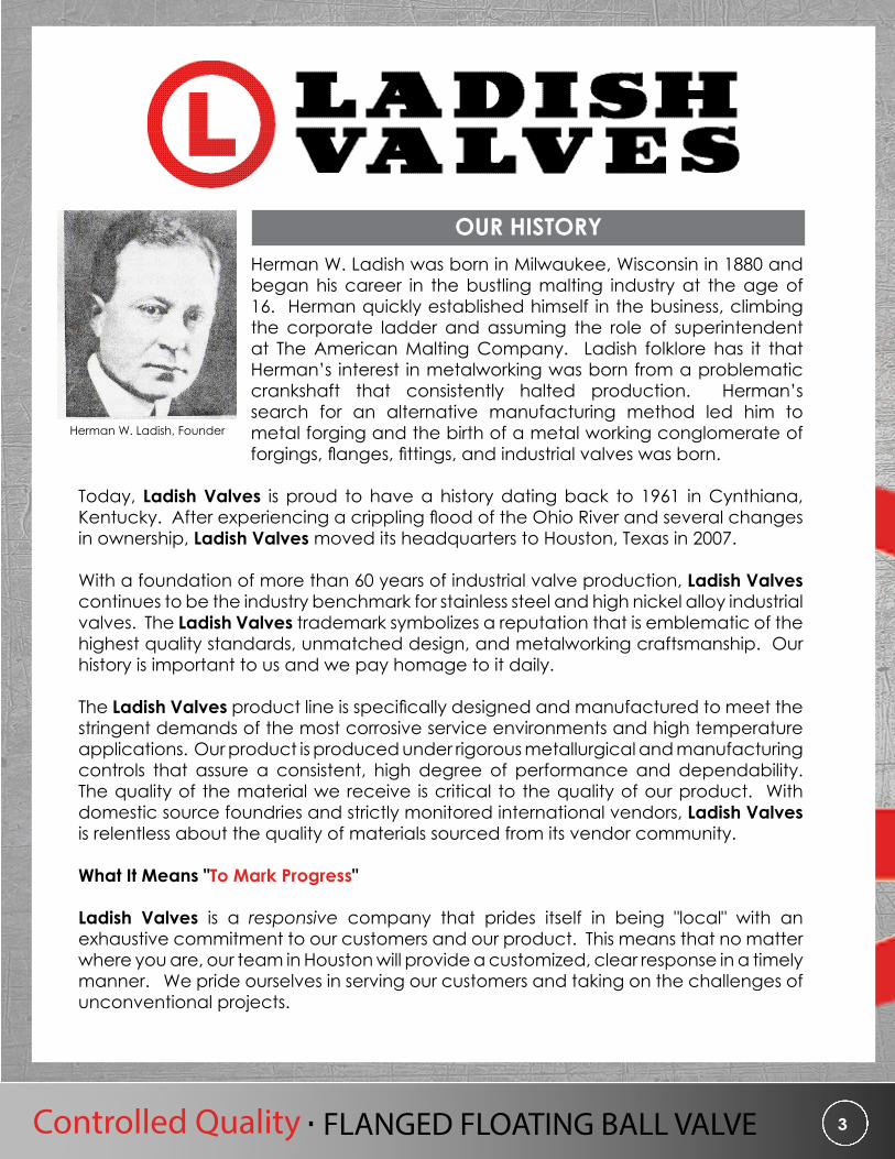
Ladish Product Line Catalogs
CATALOG 821
CATALOG 221CATALOG 421

7603 Bluff Point Dr.Houston, TX 77086281-880-8560
6
CATALOG 421Flanged Floating Ball Valve

Controlled Quality FLANGED FLOATING BALL VALVEControlled Quality FLANGED FLOATING BALL VALVE 7
Flanged Quarter-Turn ProductsOil & Gas, Petrochemical & Chemical markets
Catalog 421 serves to highlight the Ladish Valves line of flanged floating ball valve products. The products featured within include our cast two-piece and uni-body flanged floating ball valve designs in both packing and o-ring stem designs as well as our bar-stock two-piece flanged packing stem design.Ladish Valves stocks these valves in a variety of materials from carbon steel to exotic alloys and pressure classes ranging from 150 to 600. Our manufacturing facility allows for inventory storage, machining, product assembly, testing and material conformance control. With in-house non-destructive examination (NDE) capabilities and a fully integrated machine shop, quick deliveries and customer requirements are achieved in a timely, quality controlled manner.The Ladish ball valve product line is designed to API 6D and API 608, and produced in conformance with API Q1 quality system. The facility carries an ISO 9001 quality system and is certified per PED 97/23/EC.
Ladish Valves designs and manufactures its flanged floating ball valves to the following industry standards:
ITEM INDUSTRY STANDARDPRESSURE - TEMPERATURE RATINGS (1) ASME B16.34
FACE-TO-FACE DIMENSIONS ASME B16.10
END FLANGE DIMENSIONS ASME B16.5
PRESSURE TEST API 598 / API 6D
FIRESAFE TEST API 607
DESIGN STANDARD API 608, API 6D, ASME B16.34
ACTUATOR MOUNT ISO 5211
CASTING QUALITY MSS SP55, ASME B16.34 (2)
QUALITY MANAGEMENT API Q1, ISO 9001, CE-PED
1. For seat materials, see Ladish Valves pressure-temperature ratings on page 27.
2. ASME B16.34 used for evaluating NDT examinations of castings.
Finished Parts CF8M (316 Stainless Steel) Inventory
Flanged Floating Ball Valve
API 607 Fire Test (certifications available upon request)

7603 Bluff Point Dr.Houston, TX 77086281-880-8560
8
The Ladish Valves figure number is compromised of 16 alpha numeric digits defining the required product in detail. Our aim is to provide you with precisely what you need. If you need assistance, give our knowledgeable sales staff a call at (281)880-8560 with the leading 4 digits and we can guide you through the rest.
EXAMPLE: P815-L053-GF03-A40M 4” CL150 RF BALL A351 CF8M TR 316 TFM GRF B8MCL1 FIRESAFE NACE
How to Order Ladish Flanged Floating Ball Valve
P 8 1 5 403 A05L G 03P - Packing
R - Oring
8 - Cast Two Piece Full Bore
7 - Cast Two Piece Standard Bore
9 - Cast Unibody Standard Bore
2 - Bar Stock Two Piece Full Bore
5 - RF
F- FF
J - RTJ
1 - 150
3 - 300
6 - 600
A - Actuator
B - Bare Stem
G - Gear
L- Lever O - Oval Handle
0 - Same as Body
3 - 316SS
A - Alloy 20
C- Inc 600
M - Monel
H - Hast C
A - Viton® A
B - Buna N
E - EPDM
G- Graphoil
H - HNBR (ED)
R - Low Temp Buna
T - PTFE
W- Viton® B
Y- Viton® GF (ED)
Z- AFLAS®
OTHER MATERIALS AVAILABLE
UPON REQUEST
05 - 1/2”
07 - 3/4”
10 - 1”
15 - 1-1/2”
20 - 2”
30 - 3”
40 - 4”
60 - 6”
80 - 8”
81 - 10”
82 - 12”
01 - B8CL1/8
02 - B8CL2/8
03 - B8MCL1/ 8M
04 - B8MCL2/ 8M
05 - B7/2H
06 - B7M/2HM
07 - ALLOY 20
08 - MONEL 400
09 - GR660
10 - L7/7
11 - INC 800
12 - HAST C
13 - B6/6
14 - B16/16
15 - K500
16 - A320 B8CL2/8
17 - B8CL2/8A
18 - B16/7
20 - L7M/7M
A - N/A
B - Cleaned
C - Cryogenic
L - Live Load
O - Cryogenic Live Load
V - Uni Directional
W - Chain Wheel Operated
Valve Style
Construct &
Valve TypeANSI Class
End Connect Oper.
Body/Cap Mat’l
TrimPacking
&Gasket
Bolting&
Nuts
Misc. Option Size
Design Fire-Safe
NACE
MM - API 608 Fire Safe NACE
N - API 608 Fire Safe Non-NACE
P - API 608 Non-Fire Safe NACE
Q - API 608 Non-Fire Safe Non- NACE
R - API 6D Fire Safe NACE
S - API 6D Fire Safe Non-NACE
T - API 6D Non-Fire Safe NACE
U - API 6D Non-Fire Safe Non-NACE
FC - Carbon Filled TFMC
D - Delrin®
F - TFM
N - Nylon Devlon® P - PEEK® M - Metal
V - Vespel®
Seat
Materials of Construction71 A216 WCB / WCC 16 A351 CK3MCUN 26 A494 N7M 37 A494 CZ100 60 B367 GRC2
72 A352 LCC / LCB 17 A351 CN3MN 30 A494 M35-1 38 A494 CY40 CL.2 61 B367 GRC3
05 A351 CF8M 20 A494 CW12MW 31 A494 M35-2 52 A995 CD4MCUN-GR1B 62 B367 GRC7
10 A351 CG8M 21 A494 CW6M 32 A494 M30C 53 A995 CE8MN-GR2A 63 B752 GR702C
11 A351 CG3M 22 A494 CW2M 33 A494 CY40 54 A995 CD6MN-GR3ABAR STOCK
EQUIVALENTS ALSO
AVAILABLE
12 A351 CF8C 23 A494 CX2MW 34 A494 CW6MC 55 A995 CD3MN-GR4A
15 A351 CN7M 24 A494 CX2M 35 A351 CT15C 56 A995 CE3MN-GR5A
25 A494 N12MV 36 A494 CU5MCuC 57 A995 CD3MWCUN-GR6A

Controlled Quality FLANGED FLOATING BALL VALVE 9
Ladish flanged floating ball valves are designed to meet the most current industry standards and are manufactured in accordance with API Q1 quality system. Regular participation on standard committees including MSS and API assist in insuring our product is compliant. The Ladish Valves line of flanged floating ball valves has undergone extensive fire testing in accordance with API 607 and meet both API 608 and API 6D design standards.
= Long Pattern = Short Pattern = Long / Short Pattern
CLASS MODEL SEAL BODY BORE ENDS 1/2” 3/4” 1” 1 1/2” 2”
150 P2 PACKING 2 PIECE BAR-STOCK FULL RF X X X X X
300 P2 PACKING 2 PIECE BAR-STOCK FULL RF X X X X X
600 P2 PACKING 2 PIECE BAR-STOCK FULL RF X X X X X
CLASS MODEL SEAL BODY BORE ENDS 1/2” 3/4” 1” 1 1/2” 2” 3” 4” 6” 8” 10” 12”
150
P8 PACKING 2 PIECE FULL RF X X X X X X X X X X X
P7 PACKING 2 PIECE STANDARD RF - - - - X X X - - - -
P9 PACKING UNI-BODY STANDARD RF - - - - X X X X X X X
300
P8 PACKING 2 PIECE FULL RF X X X X X X X X X X X
P7 PACKING 2 PIECE STANDARD RF - - - - X X X - - - -
P9 PACKING UNI-BODY STANDARD RF - - - - X X X X X X -
600P8 PACKING 2 PIECE FULL RF X X X X X X X - - - -
P7 PACKING 2 PIECE STANDARD RF - - - - X X X X - - -
= Long Pattern = Short Pattern = Long / Short Pattern
CLASS MODEL SEAL BODY BORE ENDS 1/2” 3/4” 1” 1 1/2” 2” 3” 4” 6” 8” 10” 12”
150R8 O-RING 2 PIECE FULL RF - - - X X X X X X X X
R7 O-RING 2 PIECE STANDARD RF - - - - X X X - - - -
R9 O-RING UNI-BODY STANDARD RF - - - - X X X X X X X
300R8 O-RING 2 PIECE FULL RF - - - X X X X X X X -
R7 O-RING 2 PIECE STANDARD RF - - - - X X X - - - -
R9 O-RING UNI-BODY STANDARD RF - - - - X X X X X X -
600R8 O-RING 2 PIECE FULL RF - - - X X X X - - - -
R7 O-RING 2 PIECE STANDARD RF - - - - X X X X - - -
= Long Pattern = Short Pattern = Long / Short Pattern
Product Range: Packing Design
Product Range: O-Ring Design
Product Range: Bar Stock Design

7603 Bluff Point Dr.Houston, TX 77086281-880-8560
10
These standard design features, coupled with the Ladish Valves product range and vast material selection combine to make us the premier choice for your quarter-turn product requirements.
Ball Position IndicatorDouble D stem design easily allows for quick identification of ball position even when handle has been removed. Locking provision and travel stops at both the closed and opened positions.
Direct Actuator Mounting CapabilitiesThe Ladish ball valve design eliminates the need for a bracket and coupler when mounting an actuator, thus reducing cost while supporting any space constraints. The ISO 5211 actuator mounting pad is integral to the valve body and still allows operator to inspect packing and make adjustments as required.
Live LoadAll stem seals come “live loaded” with the addition of spring washers above the gland flange nut for improved sealing performance and quick adjustment without removal of operator.
Select Design Features • Spiral wound gasket enhances protection in case
of a fire event and for improved fugitive emissions performance.
• Anti-static feature enables electrical conductivity between both the stem and body and the stem and ball.
• Cavity vent at the top of the ball and proprietary seat design serve to maintain pressure equalization between the line and body cavity in both open and closed positions.
• Blow out proof stem and stem thrust bearing allow for safe and extended high-cycle operation.
• Encapsulated body bolting to prevent threads from corrosion.
Pressure Relieving Seat to Vent Cavity in Closed Position
Anti-Static Contact between Stem
and Body
Secondary Fire Sealing Surface
Spiral Wound Gasket Secondary Seal
Blow Out Proof Stem Design
Anti-Static Contact between Stem and Ball
Cavity Vent at Open Position
Stem Thrust Bearing for High Cycle
Primary O-Ring Seal
Standard Design Features

Controlled Quality FLANGED FLOATING BALL VALVE 11
Figure 1: Stem Packing Design Before Fire
Figure 3: O-Ring Design Before Fire
Figure 2: Stem Packing Design After Fire
Figure 4: O-Ring Design After Fire
The Ladish Valves line of flanged floating ball valves are designed in-house by Ladish engineers. The product line is engineered for fire safety and has been fire tested to API 607 standards. The illustrations below depict the metal-to-metal contact achieved during a fire event for both stem packing (Figures 1, 2) and o-ring (Figures 3, 4) sealing designs. Ladish Valves fire safe certificates are available, upon request, for the complete product range. Please contact your Ladish Valves sales representative for further information.
Fire Safe Design Features
Metal-to-Metal Contact
Metal-to-Metal Contact
7603 Bluff Point Dr.Houston, TX 77086281-880-8560
12
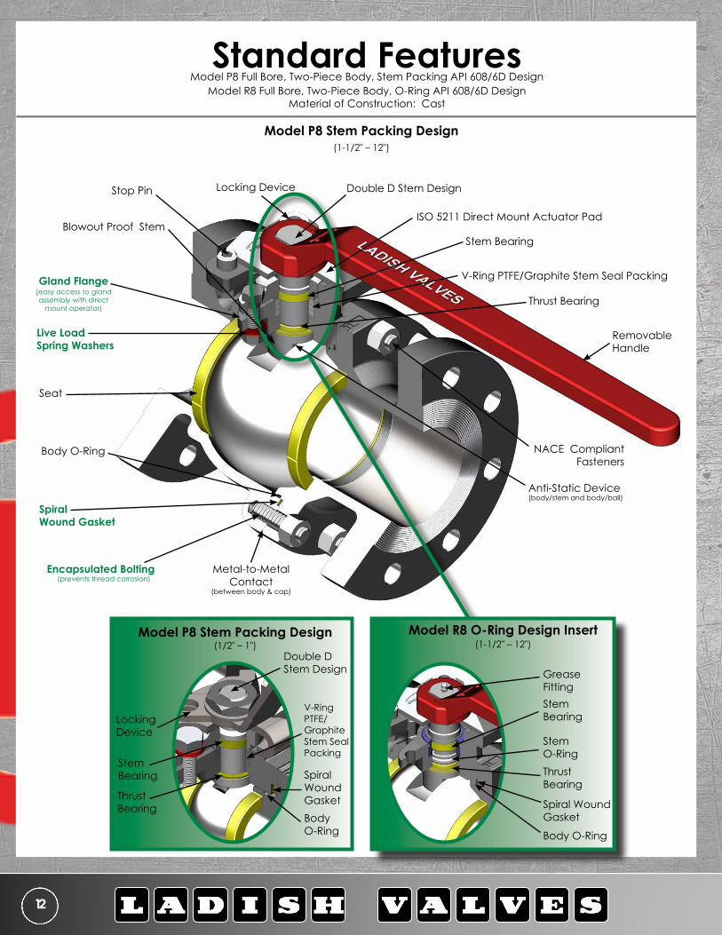
Model P8 Stem Packing Design(1/2" – 1")
Stop Pin
Removable Handle
Live Load Spring Washers
ISO 5211 Direct Mount Actuator PadBlowout Proof Stem
NACE Compliant Fasteners
Encapsulated Bolting(prevents thread corrosion)
Anti-Static Device (body/stem and body/ball)
Double D Stem Design
Seat
V-Ring PTFE/Graphite Stem Seal PackingGland Flange
Metal-to-Metal Contact
(between body & cap)
Spiral Wound Gasket
Body O-Ring
Model P8 Stem Packing Design(1-1/2" – 12")
Locking Device
Thrust Bearing
Stem Bearing
Standard Features Model P8 Full Bore, Two-Piece Body, Stem Packing API 608/6D Design
Model R8 Full Bore, Two-Piece Body, O-Ring API 608/6D Design Material of Construction: Cast
(easy access to gland assembly with direct
mount operator)
Double D Stem Design
Locking Device
Thrust Bearing
Stem Bearing
V-Ring PTFE/ Graphite Stem Seal Packing
Spiral Wound GasketBody O-Ring
Grease FittingStem Bearing
Model R8 O-Ring Design Insert(1-1/2" – 12")
Thrust Bearing
Stem O-Ring
Body O-Ring
Spiral Wound Gasket

Controlled Quality FLANGED FLOATING BALL VALVE 13
150Model P8, Class 150, 1/2” – 12” - Model R8, Class 150, 1” – 12” WEIGHT
LBSØd1 L D1 H1 ØD ØC Øg t f N Øh
1/2” 0.50 4.25 5.00 3.42 3.50 2.38 1.38 0.31 0.06 4 0.63 4
3/4” 0.75 4.63 5.00 3.53 3.88 2.75 1.68 0.34 0.06 4 0.63 6
1” 1.00 5.00 6.25 4.39 4.25 3.12 2.00 0.38 0.06 4 0.63 8
1-1/2” 1.50 6.50 10.00 5.00 5.00 3.88 2.88 0.50 0.06 4 0.63 14
2” 2.00 7.00 16.56 6.13 6.00 4.75 3.63 0.56 0.06 4 0.75 25
3” 3.00 8.00 19.69 7.91 7.50 6.00 5.00 0.69 0.06 4 0.75 54
4” 4.00 9.00 19.69 8.74 9.00 7.50 6.19 0.88 0.06 8 0.75 87
6” 6.00 15.50 59.06 11.99 11.00 9.50 8.50 0.94 0.06 8 0.88 190
8” 8.00 18.00 63.00 15.38 13.50 11.75 10.62 1.06 0.06 8 0.88 362
10” 10.00 21.00 63.00 17.50 16.00 14.25 12.75 1.12 0.06 12 1.00 539
12” 12.00 24.00 63.00 20.50 19.00 17.00 15.00 1.19 0.06 12 1.00 646
300Model P8, Class 300, 1/2” – 12” - Model R8, Class 300, 1” – 12” WEIGHT
LBSØd1 L D1 H1 ØD ØC Øg t f N Øh1/2” 0.50 5.50 5.00 3.42 3.75 2.62 1.38 0.50 0.06 4 0.63 6
3/4” 0.75 6.00 5.00 3.53 4.62 3.25 1.68 0.56 0.06 4 0.75 9
1” 1.00 6.50 6.32 4.39 4.88 3.50 2.00 0.63 0.06 4 0.75 12
1-1/2” 1.50 7.50 9.60 5.22 6.12 4.50 2.88 0.81 0.06 4 0.88 18
2” 2.00 8.50 16.56 6.13 6.50 5.00 3.63 0.81 0.06 8 0.75 32
3” 3.00 11.12 19.69 7.91 8.25 6.62 5.00 1.06 0.06 8 0.88 72
4” 4.00 12.00 19.69 8.74 10.00 7.88 6.19 1.19 0.06 8 0.88 120
6” 6.00 15.88 59.06 12.56 12.50 10.62 8.50 1.38 0.06 12 0.88 256
8” 8.00 19.75 63.00 15.38 15.00 13.00 10.62 1.56 0.06 12 1.00 475
10” 10.00 22.38 63.00 17.50 17.50 15.25 12.75 1.81 0.06 16 1.13 722
12” 12.00 25.50 63.50 20.50 20.50 17.75 15.00 2.00 0.06 16 1.25 866
600Model P8, Class 600, 1/2” – 4” - Model R8, Class 600, 1” – 4” WEIGHT
LBSØd1 L D1 H1 ØD ØC Øg t f N Øh
1/2” 0.50 6.50 5.00 3.42 3.75 2.63 1.38 0.63 0.25 4 0.63 8
3/4” 0.75 7.50 5.00 3.67 4.63 3.25 1.68 0.68 0.25 4 0.75 11
1” 1.00 8.50 6.32 4.39 4.88 3.50 2.00 0.68 0.25 4 0.75 15
1-1/2” 1.50 9.50 10.00 5.22 6.13 4.50 2.88 0.94 0.25 4 0.88 23
2” 2.00 11.50 16.56 6.42 6.50 5.00 3.63 1.00 0.25 8 0.75 42
3” 3.00 14.00 19.69 8.44 8.25 6.62 5.00 1.25 0.25 8 0.88 98
4” 4.00 17.00 59.06 11.18 10.83 8.50 6.19 1.56 0.25 8 1.00 194
Dimensional Data1/2" – 1": Model P8 Full Bore, Two-Piece Body, Pressure Classes: 150, 300, 600 (LEFT)
1 1/2" – 12": Model P8/R8 Full Bore, Two-Piece Body, Pressure Classes: 150, 300, 600 (RIGHT)

7603 Bluff Point Dr.Houston, TX 77086281-880-8560
14
Stop Pin
Removable Handle
Live Load Spring Washers
ISO 5211 Direct Mount Actuator Pad
Blowout Proof Stem
NACE Compliant Fasteners
Encapsulated Bolting(prevents thread corrosion)
Anti-Static Device (body/stem and body/ball)
Double D Stem Design
Seat
V-Ring PTFE/Graphitic Stem Seal PackingGland Flange
Metal-to-Metal Contact (between body & cap)
Spiral Wound Gasket
Body O-Ring
Model P7 Stem Packing Design
Locking Device
Thrust Bearing
Stem Bearing
(easy access to gland assembly with direct
mount operator)
Standard Features Model P7 Standard Bore, Two-Piece Body, Stem Packing API 608/6D Design
Model R7 Standard Bore, Two-Piece Body, O-Ring API 608/6D Design Material of Construction: Cast
Model R7 O-Ring Design Insert
Grease FittingStem Bearing
Thrust Bearing
Stem O-Ring
Body O-Ring
Spiral Wound Gasket

Controlled Quality FLANGED FLOATING BALL VALVE 15
150 Model P7, Class 150, 2” – 4” - Model R7, Class 150, 2” – 4” WEIGHT LBSØd1 Ød2 L D1 H1 ØD ØC Øg t f N Øh
2” 2.00 1.50 7.00 10.00 5.22 6.00 4.75 3.63 0.56 0.06 4 0.75 21
3” 3.00 2.00 8.00 16.54 6.13 7.50 6.00 5.00 0.69 0.06 4 0.75 33
4” 4.00 3.00 9.00 19.69 7.92 9.00 7.50 6.19 0.88 0.06 8 0.75 65
300 Model P7, Class 300, 2” – 4” - Model R7, Class 300, 2” – 4” WEIGHT LBSØd1 Ød2 L D1 H1 ØD ØC Øg t f N Øh
2” 2.00 1.50 8.50 10.00 5.22 6.50 5.00 3.63 0.81 0.06 8 0.75 28
3” 3.00 2.00 11.12 16.54 6.13 8.25 6.62 5.00 1.06 0.06 8 0.88 48
4” 4.00 3.00 12.00 19.69 7.92 10.00 7.88 6.19 1.19 0.06 8 0.88 93
600 Model P7, Class 600, 2” – 6” - Model R7, Class 600, 2” – 6” WEIGHT LBSØd1 Ød2 L D1 H1 ØD ØC Øg t f N Øh
2” 2.00 1.50 11.50 10.00 5.22 6.50 5.00 3.63 1.00 0.25 8 0.75 36
3” 3.00 2.00 14.00 16.54 6.45 8.25 6.62 5.00 1.25 0.25 8 0.88 62
4” 4.00 3.00 17.00 19.69 8.45 10.75 8.50 6.19 1.50 0.25 8 1.00 138
6” 6.00 4.00 22.00 59.06 11.18 14.00 11.50 8.50 1.88 0.25 12 1.12 277
2” – 6” Model P7/R7 Standard Bore, 2 piece Pressure classes 150, 300, 600
Model P7 Standard Bore, Two-Piece Body, Stem Packing API 608/6D Design Model R7 Standard Bore, Two-Piece Body, O-Ring API 608/6D Design
Material of Construction: Cast
Dimensional Data

7603 Bluff Point Dr.Houston, TX 77086281-880-8560
16
Stop Pin
Removable Handle
Live Load Spring Washers
ISO 5211 Direct Mount Actuator Pad
Blowout Proof Stem
Anti-Static Device (body/stem and body/ball)
Double D Stem Design
Seat
V-Ring PTFE/Graphite Stem Seal Packing
Gland Flange
Spiral Wound Gasket
Body O-Ring
Locking Device
Thrust Bearing
Stem Bearing
(easy access to gland assembly with direct
mount operator)
Model P9 Stem Packing Design
Standard Features Model P9 Standard Bore, Uni-Body, Stem Packing API 608/6D Design
Model R9 Standard Bore, Uni-Body, O-Ring API 608/6D Design Material of Construction: Cast
Threaded Insert (prevents thread corrosion)
Grease Fitting
Stem Bearing
Thrust Bearing
Stem O-Ring
Body O-Ring
Spiral Wound Gasket
Model R9 O-Ring Design Insert

Controlled Quality FLANGED FLOATING BALL VALVE 17
150 Model P9, Class 150, 2” – 12” - Model R9, Class 150, 2” – 12” WEIGHT LBSØd1 Ød2 L D1 H1 ØD ØC Øg t f N Øh
2” 2.00 1.50 7.00 16.56 6.13 6.00 4.75 3.63 0.56 0.06 4 0.75 20
3” 3.00 2.00 8.00 19.69 7.91 7.50 6.00 5.00 0.69 0.06 4 0.75 36
4” 4.00 3.00 9.00 19.69 8.74 9.00 7.50 6.19 0.88 0.06 8 0.75 55
6” 6.00 4.00 10.50 19.69 9.27 11.00 9.50 8.50 0.94 0.06 8 0.88 102
8” 8.00 6.00 11.50 59.00 12.00 13.50 11.75 10.62 1.06 0.06 8 0.88 192
10” 10.00 7.36 13.00 63.00 14.88 16.00 14.25 12.75 1.12 0.06 12 1.00 310
12” 12.00 9.00 14.00 63.00 16.44 19.00 17.00 15.00 1.19 0.06 12 1.00 362
300 Model P9, Class 300, 2” – 12” - Model R9, Class 300, 2” – 12” WEIGHT LBSØd1 Ød2 L D1 H1 ØD ØC Øg t f N Øh
2” 2.00 1.50 8.50 16.56 6.13 6.50 5.00 3.63 0.81 0.06 8 0.75 25
3” 3.00 2.00 11.12 19.69 7.91 8.25 6.62 5.00 1.06 0.06 8 0.88 52
4” 4.00 3.00 12.00 19.69 8.74 10.00 7.88 6.19 1.19 0.06 8 0.88 84
6” 6.00 4.00 15.88 19.69 9.27 12.50 10.62 8.50 1.44 0.06 12 0.88 150
8” 8.00 6.00 16.50 59.00 12.00 15.00 13.00 10.62 1.62 0.06 12 1.00 260
10” 10.00 7.36 18.00 63.00 14.88 17.50 15.25 12.75 1.88 0.06 16 1.12 411
12” 12.00 9.00 19.75 63.00 16.44 20.50 17.50 15.00 1.94 0.06 16 1.25 695
D1
D1
H1
Ød2 Ød1 Øg ØD
tf
L
N-Øhon ØC B.C
2” – 12” Model P9/R9 Standard Bore, Uni-Body Pressure classes 150, 300
Model P9 Standard Bore, Uni-Body, Stem Packing API 608/6D Design Model R9 Standard Bore, Uni-Body, O-Ring API 608/6D Design
Material of Construction: Cast
Dimensional Data

7603 Bluff Point Dr.Houston, TX 77086281-880-8560
18
Standard FeaturesModel P2 Full Bore, Two-Piece, Stem Packing API 608
Material of Construction: Bar-Stock
Model P2 Stem Packing Design(1-1/2" thru 2")
Model P2 Stem Packing Design(1/2" thru 1")
Lock Nut
Stop Bracket
Removable Handle
Live Load Spring Washers
ISO 5211 Direct Mount Actuator Pad
Blowout Proof Stem
NACE Compliant Fasteners
Encapsulated Bolting(prevents thread corrosion)
Anti-Static Device (body/stem and body/ball)
Double D Stem Design
Seat
V-Ring PTFE/Graphite Stem Seal Packing
Gland Flange
Metal-to-Metal Contact (between body & cap)
Spiral Wound Gasket
Locking Device
Thrust Bearing
Stem Bearing
(easy access to gland assembly with direct
mount operator)
Removable Handle (oval handle available)
Lockwasher
Anti-Static Device (body/stem and body/ball)
Spiral Wound Gasket Metal-to-Metal
Contact (between body & cap)
Double D Stem Design
NACE Compliant Fasteners
V-Ring PTFE/ Graphite Stem Seal Packing
Thrust Bearing
Stem Bearing

Controlled Quality FLANGED FLOATING BALL VALVE 19
150 Model P2, Class 150, 1/2” – 2” WEIGHT LBSØd1 L D1 H1 ØD ØC Øg t f N Øh
1/2” 0.50 4.25 5.00 3.42 3.50 2.38 1.38 0.31 0.06 4 0.63 4
3/4” 0.75 4.63 5.00 3.53 3.88 2.75 1.68 0.34 0.06 4 0.63 6
1” 1.00 5.00 6.32 4.39 4.25 3.12 2.00 0.38 0.06 4 0.63 8
1-1/2” 1.50 6.50 10.00 5.22 5.00 3.88 2.88 0.50 0.06 4 0.63 18
2” 2.00 7.00 16.56 6.13 6.00 4.75 3.63 0.56 0.06 4 0.75 25
300 Model P2, Class 300, 1/2” – 2” WEIGHT LBSØd1 L D1 H1 ØD ØC Øg t f N Øh
1/2” 0.50 5.50 5.00 3.42 3.75 2.62 1.38 0.50 0.06 4 0.63 6
3/4” 0.75 6.00 5.00 3.53 4.62 3.25 1.68 0.56 0.06 4 0.75 9
1” 1.00 6.50 6.32 4.39 4.88 3.50 2.00 0.63 0.06 4 0.75 12
1-1/2” 1.50 7.50 10.00 5.22 6.12 4.50 2.88 0.81 0.06 4 0.88 25
2” 2.00 8.50 16.56 6.13 6.50 5.00 3.63 0.88 0.06 8 0.75 32
600 Model P2, Class 600, 1/2” – 2” WEIGHT LBSØd1 L D1 H1 ØD ØC Øg t f N Øh
1/2” 0.50 6.50 5.00 3.42 3.75 2.62 1.38 0.56 0.25 4 0.63 8
3/4” 0.75 7.50 5.00 3.67 4.62 3.25 1.68 0.62 0.25 4 0.75 11
1” 1.00 8.50 6.32 4.39 4.88 3.50 2.00 0.69 0.25 4 0.75 15
1-1/2” 1.50 9.50 10.00 5.22 6.12 4.50 2.88 0.88 0.25 4 0.88 32
2” 2.00 11.50 16.56 6.42 6.50 5.00 3.63 1.00 0.25 8 0.75 42
1/2” – 1” Model P2 Full Bore, 2 piece Pressure classes 150, 300, 600
Model P2 Full Bore, Two-Piece, Stem Packing API 608 Material of Construction: Bar-Stock
1-1/2” – 2” Model P2 Full Bore, 2 piece Pressure classes 150, 300, 600
Dimensional Data
7603 Bluff Point Dr.Houston, TX 77086281-880-8560
20
1
4
7A
3
226
70
14
24
25
20
8A
8B
28A
8
30A
32
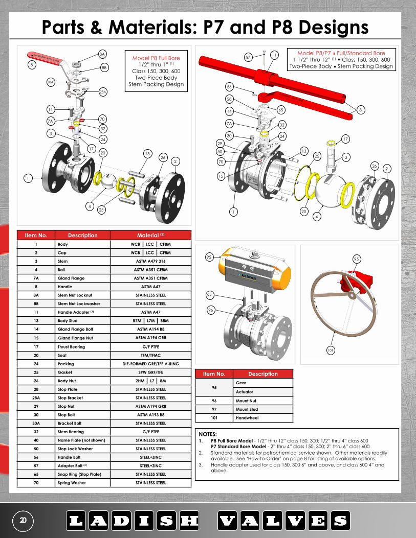
Model P8 Full Bore 1/2” thru 1” (1)
Class 150, 300, 600 Two-Piece Body
Stem Packing Design
13
Item No. Description Material (2)
1 Body WCB LCC CF8M
2 Cap WCB LCC CF8M
3 Stem ASTM A479 316
4 Ball ASTM A351 CF8M
7A Gland Flange ASTM A351 CF8M
8 Handle ASTM A47
8A Stem Nut Locknut STAINLESS STEEL
8B Stem Nut Lockwasher STAINLESS STEEL
11 Handle Adapter (3) ASTM A47
13 Body Stud B7M L7M B8M
14 Gland Flange Bolt ASTM A194 B8
15 Gland Flange Nut ASTM A194 GR8
17 Thrust Bearing G/F PTFE
20 Seat TFM/TFMC
24 Packing DIE-FORMED GRF/TFE V-RING
25 Gasket SPW GRF/TFE
26 Body Nut 2HM L7 8M
28 Stop Plate STAINLESS STEEL
28A Stop Bracket STAINLESS STEEL
29 Stop Nut ASTM A194 GR8
30 Stop Bolt ASTM A193 B8
30A Bracket Bolt STAINLESS STEEL
32 Stem Bearing G/F PTFE
40 Name Plate (not shown) STAINLESS STEEL
50 Stop Lock Washer STAINLESS STEEL
56 Handle Bolt STEEL+ZINC
57 Adapter Bolt (3) STEEL+ZINC
65 Snap Ring (Stop Plate) STAINLESS STEEL
70 Spring Washer STAINLESS STEEL
Item No. Description
95Gear
Actuator
96 Mount Nut
97 Mount Stud
101 Handwheel
101
9595
96
97
NOTES:1. P8 Full Bore Model - 1/2” thru 12” class 150, 300; 1/2” thru 4” class 600
P7 Standard Bore Model - 2” thru 4” class 150, 300; 2” thru 6” class 6002. Standard materials for petrochemical service shown. Other materials readily
available. See ‘How-to-Order’ on page 8 for listing of available options.3. Handle adapter used for class 150, 300 6” and above, and class 600 4” and
above.
1157
8
56
65
28
7A 32
2430
29
70
15
1
26
17
13
420
3
2
25
14
Parts & Materials: P7 and P8 DesignsModel P8/P7 Full/Standard Bore
1-1/2” thru 12” (1) Class 150, 300, 600 Two-Piece Body Stem Packing Design
17 50

Controlled Quality FLANGED FLOATING BALL VALVE 21
1157
8
25
17
3
2
Model P9 - Standard Bore 2” thru 12” (1)
Class 150, 300 Uni-body
Stem Packing Design
56
28
7A
30
29
70
14
1
4
20
65
32
24
15
95
96
97
Item No. Description Material (2)
1 Body WCB LCC CF8M
2 Cap Insert WCB LCC CF8M
3 Stem ASTM A479 316
4 Ball ASTM A351 CF8M
7A Gland Flange ASTM A351 CF8M
8 Handle ASTM A47
11 Handle Adapter (3) ASTM A197
14 Gland Flange Bolt ASTM A193 B8
15 Gland Flange Nut ASTM A194 GR8
17 Thrust Bearing G/F PTFE
20 Seat TFM/TFMC
24 Packing DIE-FORMED GRF/TFE V-RING
25 Gasket SPW GRF/TFE
28 Stop Plate STAINLESS STEEL
29 Stop Nut ASTM A194 GR8
30 Stop Bolt ASTM A193 B8
32 Stem Bearing G/F PTFE
40 Name Plate (not shown) STAINLESS STEEL
50 Stop Lock Washer STAINLESS STEEL
56 Handle Bolt STEEL+ZINC
57 Adapter Bolt (3) STEEL+ZINC
65 Snap Ring (Stop Plate) STAINLESS STEEL
70 Spring Washer STAINLESS STEEL
Item No. Description
95Gear
Actuator
96 Mount Nut
97 Mount Stud
101 Handwheel
NOTES:1. P9 Standard Bore Model - 2” thru 12” class 150, 300 2. Standard materials for petrochemical service shown. Other
materials readily available. See ‘How-to-Order’ on page 8 for listing of available options.
3. Handle adapter used for class 150, 300 6” and above.
101
95
Parts & Materials: P9 Design
50

7603 Bluff Point Dr.Houston, TX 77086281-880-8560
22
57
11
8
39
61
17
3 26 2
66
2025
6013
56
1
30
65
62
7
28
32
50
29
Item No. Description Material (2)
1 Body WCB LCC CF8M
2 Cap WCB LCC CF8M
3 Stem ASTM A479 316
4 Ball ASTM A351 CF8M
7 Gland ASTM A351 CF8M
8 Handle ASTM A47
11 Handle Adapter (3) ASTM A47
13 Body Stud B7M L7M B8M
17 Thrust Bearing G/F PTFE
20 Seat TFM/TFMC
25 Gasket SPW GRF/TFE
26 Body Nut 2HM L7 8M
28 Stop Plate STAINLESS STEEL
29 Stop Nut ASTM A194 GR8
30 Stop Bolt ASTM A193 B8
32 Stem Bearing G/F PTFE
39 Grease Fitting STAINLESS STEEL
40 Name Plate (not shown) STAINLESS STEEL
50 Stop Lock Washer STAINLESS STEEL
56 Handle Bolt STEEL+ZINC
57 Adapter Bolt (3) STEEL+ZINC
60 O-Ring, Body VITON® GF
61 O-Ring, Stem VITON® GF
62 O-Ring, Gland VITON® GF
65 Snap Ring (Stop Plate) STAINLESS STEEL
66 Snap Ring (Gland) STAINLESS STEEL
Item No. Description
95Gear
Actuator
96 Mount Nut
97 Mount Stud
101 Handwheel
95
Model R8/R7 Full/Standard Bore 1-1/2” thru 12” (1)
Class 150, 300, 600 Two-Piece Body
Stem O-Ring Design
4
95
96
97
NOTES:1. R8 Full Bore Model - 1” thru 12” class 150, 300;
1” thru 4” class 600 (note: 1” design not pictured) R7 Standard Bore Model - 2” thru 4” class 150, 300; 2” thru 6” class 600
2. Standard materials for oil & gas service shown. Other materials readily available. See ‘How-to-Order’ on page 8 for listing of available options.
3. Handle adapter used for class 150, 300 8” and above and class 600 6” and above.
Parts & Materials: R7 and R8 Designs
101
Controlled Quality FLANGED FLOATING BALL VALVE 23
8
254
3
17
65
56
28
3262
1
30
50
29
7
39
61
66
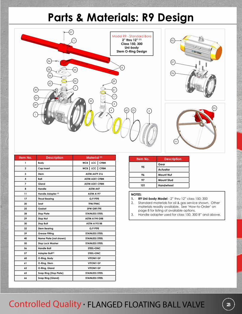
Model R9 - Standard Bore 2” thru 12” (1)
Class 150, 300 Uni-body
Stem O-Ring Design
57
11
20
60
Item No. Description Material (2)
1 Body WCB LCC CF8M
2 Cap Insert WCB LCC CF8M
3 Stem ASTM A479 316
4 Ball ASTM A351 CF8M
7 Gland ASTM A351 CF8M
8 Handle ASTM A47
11 Handle Adapter (3) ASTM A197
17 Thrust Bearing G/F PTFE
20 Seat TFM/TFMC
25 Gasket SPW GRF/TFE
28 Stop Plate STAINLESS STEEL
29 Stop Nut ASTM A194 GR8
30 Stop Bolt ASTM A193 B8
32 Stem Bearing G/F PTFE
39 Grease Fitting STAINLESS STEEL
40 Name Plate (not shown) STAINLESS STEEL
50 Stop Lock Washer STAINLESS STEEL
56 Handle Bolt STEEL+ZINC
57 Adapter Bolt(3) STEEL+ZINC
60 O-Ring, Body VITON® GF
61 O-Ring, Stem VITON® GF
62 O-Ring, Gland VITON® GF
65 Snap Ring (Stop Plate) STAINLESS STEEL
66 Snap Ring (Gland) STAINLESS STEEL
Item No. Description
95Gear
Actuator
96 Mount Nut
97 Mount Stud
101 Handwheel
101
95
95
96
97
NOTES:1. R9 Uni-body Model - 2” thru 12” class 150; 3002. Standard materials for oil & gas service shown. Other
materials readily available. See ‘How-to-Order’ on page 8 for listing of available options.
3. Handle adapter used for class 150, 300 8” and above.
Parts & Materials: R9 Design
2
7603 Bluff Point Dr.Houston, TX 77086281-880-8560
24
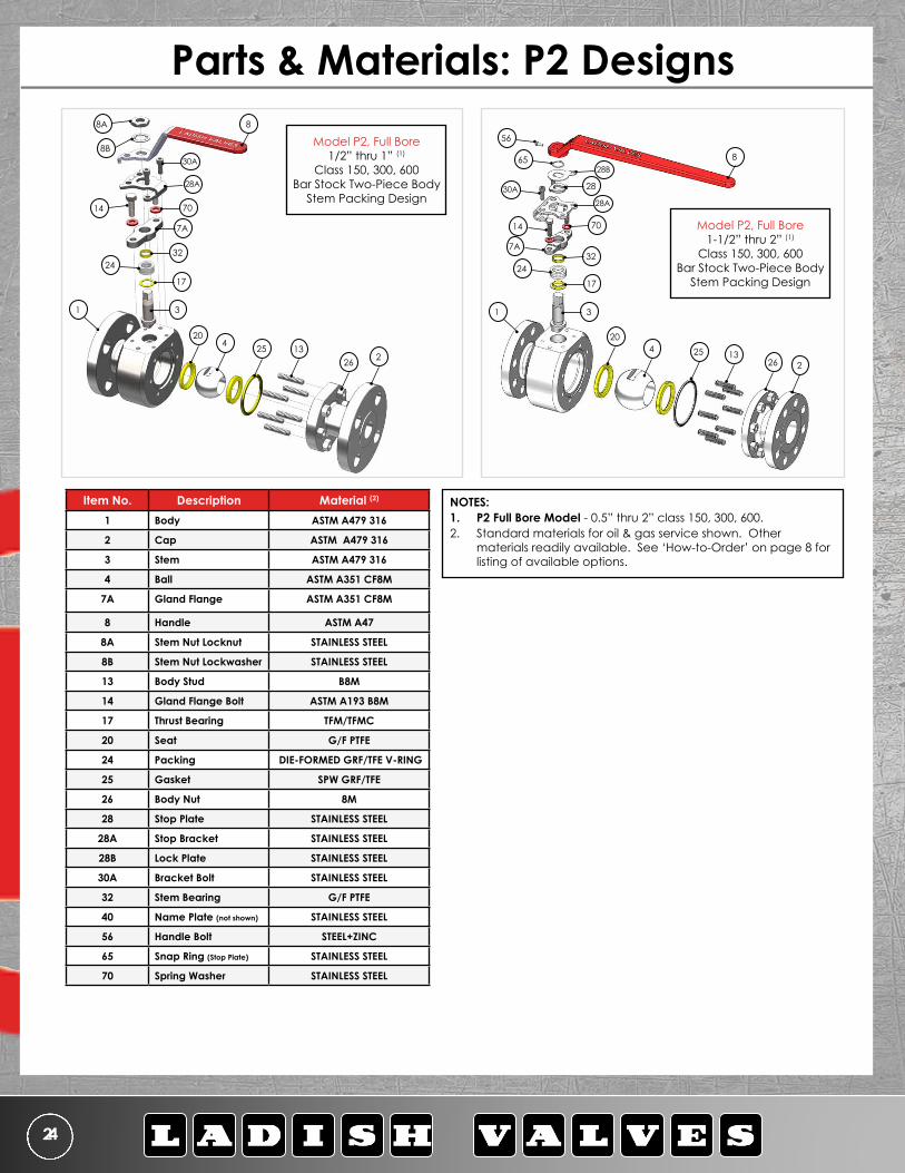
Model P2, Full Bore 1/2” thru 1” (1)
Class 150, 300, 600 Bar Stock Two-Piece Body
Stem Packing Design
NOTES:1. P2 Full Bore Model - 0.5” thru 2” class 150, 300, 600.2. Standard materials for oil & gas service shown. Other
materials readily available. See ‘How-to-Order’ on page 8 for listing of available options.
Item No. Description Material (2)
1 Body ASTM A479 316
2 Cap ASTM A479 316
3 Stem ASTM A479 316
4 Ball ASTM A351 CF8M
7A Gland Flange ASTM A351 CF8M
8 Handle ASTM A47
8A Stem Nut Locknut STAINLESS STEEL
8B Stem Nut Lockwasher STAINLESS STEEL
13 Body Stud B8M
14 Gland Flange Bolt ASTM A193 B8M
17 Thrust Bearing TFM/TFMC
20 Seat G/F PTFE
24 Packing DIE-FORMED GRF/TFE V-RING
25 Gasket SPW GRF/TFE
26 Body Nut 8M
28 Stop Plate STAINLESS STEEL
28A Stop Bracket STAINLESS STEEL
28B Lock Plate STAINLESS STEEL
30A Bracket Bolt STAINLESS STEEL
32 Stem Bearing G/F PTFE
40 Name Plate (not shown) STAINLESS STEEL
56 Handle Bolt STEEL+ZINC
65 Snap Ring (Stop Plate) STAINLESS STEEL
70 Spring Washer STAINLESS STEEL
Model P2, Full Bore 1-1/2” thru 2” (1)
Class 150, 300, 600 Bar Stock Two-Piece Body
Stem Packing Design
Parts & Materials: P2 Designs
22613254
20
3
17
2432
7A
70
28A
30A
88A
8B
14
1
22613254
20
3
17
3224
70
28A
28
6528B
56
30A
14
8
1
7A

Controlled Quality FLANGED FLOATING BALL VALVE 25
The Ladish ball valve is designed with features to extend valve life and minimize maintenance and repairs. For guidance on maintenance and repair, please visit our website and download the Flanged Floating Ball Valve Installation, Operation and Maintenance (IOM) manual.
For both the stem packing and O-Ring designs, Ladish has repair kits available. Below are standard components in each repair kit. Please call the Ladish team with figure number(s) so we can confirm component materials for repair kits.
Item No. Qty. Description17 1 Thrust Bearing20 2 Seat24 1 Packing25 1 Gasket32 1 Stem Bearing
Item No. Qty. Description17 1 Thrust Bearing20 2 Seat25 1 Gasket32 1 Stem Bearing60 1 O-Ring, Body61 1 O-Ring, Stem62 1 O-Ring, Gland
Stem Packing Design – Model P2, P7, P8, P9 Stem O-Ring Design – Model R7, R8, R9
Maintenance & Repair Kits
24
17
20
32
25
2560
17
20
62
32
61

7603 Bluff Point Dr.Houston, TX 77086281-880-8560
26
In-house Engineering CapabilitiesAll Ladish Flanged Floating Ball Valves are designed by Ladish engineers located in Houston, Texas. In addition to ball valve designs, Ladish builds and performs all required testing per API specifications. This includes seat capacity ratings, lifecycle testing, and all fire testing as required by API 607.
Advanced Engineering Tools• 3D Solid Modeling• Finite Analysis (FEA)• Flow Simulation Analysis
Rapid Prototyping of New Designs• Compare design alternatives to meet customer demands and requirements
Active in API and MSS• Provides Ladish up-to-date access to the latest standard changes
Continuous Interaction with Foundry Vendors• Communication enables quick execution of new pattern/tool changes• Ensures the quality of the Ladish product from our Foundry vendors• Casting simulation software provides product verification and casting quality
Specialty Ball Valves• Ladish ball valve design also offered in metal and graphite seats• Cryogenic ball valve offered with one-piece stem and manufactured at our Houston facility.

Controlled Quality FLANGED FLOATING BALL VALVE 27
The pressure temperature ratings for the Ladish Valves ball valve product line are determined by a combination of the body, seal and seating material. The charts below serve to be representative of our most common seat materials. For ratings on other materials, please contact a Ladish team member.
P8/R8 Model: 1/2” thru 1”P2: 1/2” thru 1”
P8/R8 Model: 1 1/2” thru 2”P7/R7, P9/R9: 2” thru 3”
P2: 1 1/2” thru 2”
P8/R8 Model: 3” thru 4” P7/R7, P9/R9: 4” thru 6”
P8/R8 Model: 6” P9/R9: 8”
Pressure & Temperature Ratings
0
200
400
600
800
1000
1200
1400
1600
0 50 100
150
200
250
300
350
400
450
500
550
Pres
sure
, psi
Temperature, degree °F
P8/R8 Series: 1/2" - 1"P7/R7, P9/R9 Series: 3/4" - 1 1/2"
PEEK
™
Devl
on®
HNBR
Buna
TFM
WCB Class 150 Rating
WCB Class 300 Rating
WCB Class 600 Rating
Vito
n®
0
200
400
600
800
1000
1200
1400
1600
0 50 100
150
200
250
300
350
400
450
500
550
Pres
sure
, psi
Temperature, degree °F
P8/R8 Series: 1-1/2" - 2"P7/R7, P9/R9 Series: 2" - 3"
PEEK
™
Devl
on®
HNBR
Buna
TFMC
TFM
WCB Class 150 Rating
WCB Class 300 Rating
WCB Class 600 Rating
Vito
n®
0
200
400
600
800
1000
1200
1400
1600
0 50 100
150
200
250
300
350
400
450
500
550
Pres
sure
, psi
Temperature, degree °F
P8/R8 Series: 3" - 4"P7/R7, P9/R9 Series: 4" - 6"
PEEK
™
Devl
on®
HNBR
Buna
WCB Class 150 Rating
WCB Class 300 Rating
WCB Class 600 Rating
Vito
n®
0
200
400
600
800
1000
1200
1400
1600
0 50 100
150
200
250
300
350
400
450
500
550
Pres
sure
, psi
Temperature, degree °F
P8/R8 Series: 6"P9/R9 Series: 8"
PEEK
™
Devl
on®
HNBR
Buna
WCB Class 150 Rating
WCB Class 300 Rating
WCB Class 600 Rating
Vito
n®
0
200
400
600
800
1000
1200
1400
1600
0 50 100
150
200
250
300
350
400
450
500
550
Pres
sure
, psi
Temperature, degree °F
P8/R8 Series: 8" - 10"P9/R9 Series: 10" - 12"
PEEK
™
Devl
on®
HNBR
Buna
WCB Class 150 Rating
WCB Class 300 Rating
WCB Class 600 Rating
Vito
n®
P8/R8 Model: 8” thru 10” P9/R9: 10” thru 12”
NOTES:1. Above class rating is for WCB - refer to the lastest edition of ASME B16.34 for P/T of other material.2. Metal seated valves P/T rating are equal to the body rating per ASME B16.34.
7603 Bluff Point Dr.Houston, TX 77086281-880-8560
28
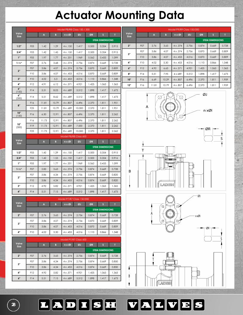
Valve Size
Model P8/R8 Class 150 / 300
A B n x ØI ØJ ØR S T
STEM DIMENSIONS
1/2” F03 1.42 1.29 4 x .150 1.417 0.500 0.354 0.915
3/4” F03 1.42 1.45 4 x .150 1.417 0.500 0.354 0.915
1” F05 1.97 1.77 4 x .201 1.969 0.562 0.433 1.099
1-1/2” F07 2.76 3.68 4 x .374 2.756 0.874 0.669 0.728
2”F07 3.86 4.07 4 x .374 2.756 0.870 0.669 0.809
F10 3.86 4.07 4 x .453 4.016 0.870 0.669 0.809
3” F10 4.02 5.3 4 x .453 4.016 1.110 0.866 1.348
4” F12 4.91 6.12 4 x .571 4.921 1.425 1.063 1.363
6” (150) F14 5.51 8.03 4 x .689 5.512 1.898 1.417 1.673
6” (300) F14 5.51 8.62 4 x .689 5.512 1.898 1.417 1.673
8”F16 11.81 10.79 4 x .807 6.496 2.370 1.811 1.951
F25 11.81 10.79 8 x .689 10.000 2.370 1.811 1.951
10” (150) F16 6.50 12.91 4 x .807 6.496 2.370 1.811 2.262
10” (300)
F16 11.73 12.91 4 x .807 6.496 2.370 1.811 2.262
F19 11.73 12.91 8 x .689 7.500 2.370 1.811 2.262
F25 11.73 12.91 8 x .689 10.000 2.370 1.811 2.262
Valve Size
Model P8/R8 Class 600
A B n x ØI ØJ ØR S T
STEM DIMENSIONS
1/2” F03 1.42 1.29 4 x .150 1.417 0.500 0.354 0.915
3/4” F03 1.42 1.55 4 x .150 1.417 0.500 0.354 0.916
1” F05 1.97 1.77 4 x .201 1.969 0.562 0.433 1.099
1-1/2” F07 2.83 3.63 4 x .374 2.756 0.874 0.669 0.728
2”F07 3.86 4.34 4 x .374 2.756 0.874 0.669 0.820
F10 3.86 4.34 4 x .453 4.016 0.874 0.669 0.820
3” F12 4.92 5.82 4 x .571 4.921 1.425 1.063 1.365
4” F14 5.51 7.15 4 x .689 5.512 1.898 1.417 1.673
Valve Size
Model P7/R7 Class 150/300
A B n x ØI ØJ ØR S T
STEM DIMENSIONS
2” F07 2.76 3.63 4 x .374 2.756 0.874 0.669 0.728
3”F07 3.86 4.07 4 x .374 2.756 0.870 0.669 0.809
F10 3.86 4.07 4 x .453 4.016 0.870 0.669 0.809
4” F10 4.02 5.30 4 x .453 4.016 1.110 0.866 1.348
Valve Size
Model P7/R7 Class 600
A B n x ØI ØJ ØR S T
STEM DIMENSIONS
2” F07 2.76 3.63 4 x .374 2.756 0.874 0.669 0.728
3”F07 3.86 4.34 4 x .374 2.756 0.874 0.669 0.850
F10 3.86 4.34 4 x .453 4.016 0.874 0.669 0.850
4” F12 4.92 5.82 4 x .571 4.921 1.425 1.063 1.365
6" F14 5.51 7.15 4 x .689 5.512 1.898 1.417 1.673
Actuator Mounting DataValve Size
Model P9/R9 Class 150/300
A B n x ØI ØJ ØR S T
STEM DIMENSIONS
2” F07 2.76 3.63 4 x .374 2.756 0.874 0.669 0.728
3”F07 3.86 4.07 4 x .374 2.756 0.870 0.669 0.809
F10 3.86 4.07 4 x .453 4.016 0.870 0.669 0.809
4” F10 4.02 5.30 4 x .453 4.016 1.110 0.866 1.348
6" F12 4.92 6.63 4 x .571 4.921 1.425 1.063 1.363
8" F14 5.51 7.95 4 x 689 5.512 1.898 1.417 1.673
10" F16 6.69 10.29 4 x .807 6.496 2.370 1.811 1.959
12" F16 11.81 10.79 4 x .807 6.496 2.370 1.811 1.959

Controlled Quality FLANGED FLOATING BALL VALVE 29
SIZE MODEL Bore PRESSURE CLASS150 300 600
1/2” P8/P2 FP 28 28 28
3/4”
P8/P2 FP 51 51 51P7 RP 18 18 18P9/DOWNSTREAM RP 16 19 -P9/UPSTREAM RP 14 17 -
1”
P8/P2 FP 97 97 92P7 RP 43 43 38P9/DOWNSTREAM RP 29 34 -P9/UPSTREAM RP 28 31 -
1-1/2”
P8/R8/P2 FP 260 255 250P7/R7 RP 80 75 70P9/R9 DOWNSTREAM RP 110 132 -P9/R9 UPSTREAM RP 105 126 -
2”
P8/R8/P2 FP 472 422 367P7/R7 RP 172 159 148P9/R9 DOWNSTREAM RP 160 192 -P9/R9 UPSTREAM RP 155 185 -
3”
P8/R8 FP 1245 1055 1000P7/R7 RP 428 428 390P9/R9 DOWNSTREAM RP 335 400 -P9/R9 UPSTREAM RP 320 378 -
4”
P8/R8 FP 2450 2140 1795P7/R7 RP 605 605 572P9/R9 DOWNSTREAM RP 490 583 -P9/R9 UPSTREAM RP 450 540 -
6”
P8/R8 FP 5350 5150 4950P7/R7 RP 1150 1150 925P9/R9 DOWNSTREAM RP 975 1170 -P9/R9 UPSTREAM RP 900 1100 -
8”
P8/R8 FP 10850 10315 -P7/R7 RP 3560 3375 -P9/R9 DOWNSTREAM RP 1267 1598 -P9/R9 UPSTREAM RP 1185 1410 -
10”
P8/R8 FP 15500 15500 -P7/R7 RP 6750 6750 -
P9/R9 DOWNSTREAM RP 2115 2598 -
P9/R9 UPSTREAM RP 2010 2370 -
12” P8/R8 FP 24000 24000 -
Flow Coefficients (Cv) and Pressure Conversion Chart
Actuator Mounting Data: Flow Coefficients
FLOw COEFFICIENTs (CV) FACTOrCapacity factors for the series P2,P7,P8,P9,R7,R8, and R9 designs listed are to be used as a reference for correct valve sizing. Cv equals the volume of water in gallons per minute that will flow through a given opening with a pressure drop of one psi.
PrEssurE CONVErsIONDirections: Formulas below may be used for pressure conversions
psi x .06894757 = bar bar x 14.50377 = psipsi x .07030697 = Kg/cm2 Kg/cm2 x 14.22334 = psi
psi x 6894.757 = Pascal Pascal x .0001450377 = psi

NOTES

TO MARK PROGRESS
7603 BLuFF POINT DrIVE HOusTON TExAs 77086
281.880.8560 (P)281.880.8061 (F)
www.LADIsHVALVEs.COm
Published technical data and general information are intended solely for the coverage of typical applications for users of Ladish Valves products featured in this catalog. Please contact Ladish Valves for specific questions, tech-nical assistance, or to produce your own study, data and conclusions related to the quality and performance of our products to a specific application. Ladish Valves is not responsible for property damage and/or personal injury that may result from failure to follow these instructions. Any information listed in this brochure is subject to change with regard to time sensitivity, error correction, product and design introduction, modification or discontinuation, as well as any other changes Ladish Valves considers appropriate.