Embed Size (px)
Citation preview
Control Valves for POWER GENERATION Applications
2
Control Valve Division
SUMMARY
0. FOREWORD .................................................................................................................................... 3
1. RANGE OF PRODUCTS FOR POWER GENERATION ............................................................................. 3
1.1. CONTROL VALVES ........................................................................................................................................................ 3 1.1.1. CV-8400 & CV-8700 – Straight-way and angle body valve with screwed seat and contoured plug ...........................3 1.1.2. CV-8450 & CV-8750 – Straight-way and angle body valve with quick-change trim ....................................................3 1.1.3. Single cage trims standard and low noise...................................................................................................................3 1.1.4. Double cage, anti-cavitation trims ..............................................................................................................................3 1.1.5. Triple cage, anti-cavitation trims ................................................................................................................................3 1.1.6. VeCo-LT, multi-path multi-stage labyrinth trims ........................................................................................................3 1.1.7. Vary-VeCo, variable stages labyrinth trims .................................................................................................................3 1.1.8. Tandem plug, multiple cage trims ..............................................................................................................................3
1.2. STEAM DESUPERHEATERS ........................................................................................................................................... 3 1.2.1. DS-3100 – Venturi Nozzle ...........................................................................................................................................3 1.2.2. DS-3200 – Fixed Area nozzle .......................................................................................................................................3 1.2.3. DS-3400 – Variable Area nozzle ..................................................................................................................................3 1.2.4. DS-3600 – Steam Atomized nozzle .............................................................................................................................3 1.2.5. DS-3700 – Actuated Multi Nozzle ...............................................................................................................................3
1.3. SYSTEMS ..................................................................................................................................................................... 3
2. TYPICAL SERVICES ........................................................................................................................... 4
3. CV-8407 / CV-8707 – SCREWED SEAT CONTOURED PLUG CONTROL VALVES ...................................... 4
3.1. Main features .............................................................................................................................................................. 4 3.2. Materials ..................................................................................................................................................................... 4 3.3. Sizes and Pressure Classes ........................................................................................................................................... 4 3.4. Seat Leakage ............................................................................................................................................................... 4
4. CV-8450 – GLOBE QUICK CHANGE CAGE VALVE ................................................................................ 5
4.1. Main Features ............................................................................................................................................................. 5 4.2. Available trims ............................................................................................................................................................ 5 4.3. Materials ..................................................................................................................................................................... 6 4.4. Sizes and Pressure Classes ........................................................................................................................................... 6 4.5. Seat leakage IEC 60534-4 / ISA FCI 70-2 ....................................................................................................................... 6 4.6. Low-noise, anti-cavitation and anti-erosion special trims details ................................................................................. 6
4.6.1. Low noise micro drilled cages .....................................................................................................................................6 4.6.2. Multi-cage trims .........................................................................................................................................................6 4.6.3. Tandem plug, multi-cage trim ....................................................................................................................................7 4.6.4. Velocity controlled, multi-path, multi-step labyrinth trim .........................................................................................7
4.7. Multi path, variable step number labyrinth trim .......................................................................................................... 7
5. DS-3000 – STEAM DESUPERHEATERS ............................................................................................... 8
5.1. DS-3111 – Venturi Nozzle Desuperheaters ................................................................................................................... 8 5.2. DS-3200 – Fixed Area Nozzle Desuperheaters .............................................................................................................. 8 5.3. DS-3400 – Variable Area Nozzles Desuperheaters ........................................................................................................ 8 5.4. DS-3600 – Steam Assisted Nozzles Desuperheaters ..................................................................................................... 9 5.5. DS-3700 – Actuated Multi Nozzles Desuperheaters ..................................................................................................... 9
6. SYSTEMS ...................................................................................................................................... 11
6.1. Steam vent to Atmosphere ........................................................................................................................................ 11 6.2. Steam pressure reducing and desuperheating systems (PRDS) .................................................................................. 11 6.3. Steam Turbine bypass Systems .................................................................................................................................. 12
7. CODING SYSTEM ........................................................................................................................... 13
7.1. VALVES ...................................................................................................................................................................... 13 7.2. DESUPERHEATERS ..................................................................................................................................................... 13 7.3. SYSTEMS ................................................................................................................................................................... 14
8. OPTIONS ....................................................................................................................................... 14
9. ACCESSORIES ................................................................................................................................ 14
Control Valves for POWER GENERATION Applications
3
Control Valve Division
0. FOREWORD
Established in 1951, AST S.p.A. is one of the first Italian manufacturers of spring-loaded safety relief valves and changeover valve
systems, in the following years, since early 80’s the production range has been extended by the introduction of control valves for
critical services.
In the recent years heavy duty control valves with special low noise and anti-cavitation solutions and complementary products such
as steam desuperheaters and steam conditioning systems for power generation field have been added to complete the production
range.
1. RANGE OF PRODUCTS FOR POWER GENERATION
Thanks to a wide range of products specially developed for service on critical applications AST can supply control valves and systems
to satisfy whichever process requirements in the power generation industry.
Conventional control valves, cage balanced, low-noise, anti-cavitation and anti-erosion labyrinth trims are available and properly
selected and sized in accordance with specific process conditions and service requirements by well expertise technical team.
Advanced technical solutions allow to warrant best performances and high reliability also for service on extreme pressure and
temperature.
Wide range of actuation solutions is available: pneumatic actuators with mechanical or hydraulic side or top mounted hand-wheels,
electric or electro hydraulic actuators.
1.1. CONTROL VALVES
1.1.1. CV-8400 & CV-8700 – Straight-way and angle body valve with screwed seat and contoured plug
1.1.2. CV-8450 & CV-8750 – Straight-way and angle body valve with quick-change trim
1.1.3. Single cage trims standard and low noise
1.1.4. Double cage, anti-cavitation trims
1.1.5. Triple cage, anti-cavitation trims
1.1.6. VeCo-LT, multi-path multi-stage labyrinth trims
1.1.7. Vary-VeCo, variable stages labyrinth trims
1.1.8. Tandem plug, multiple cage trims
1.2. STEAM DESUPERHEATERS
1.2.1. DS-3100 – Venturi Nozzle
1.2.2. DS-3200 – Fixed Area nozzle
1.2.3. DS-3400 – Variable Area nozzle
1.2.4. DS-3600 – Steam Atomized nozzle
1.2.5. DS-3700 – Actuated Multi Nozzle
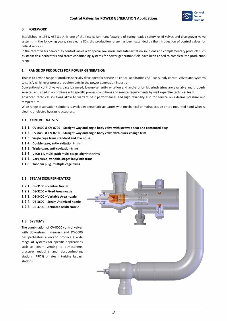
1.3. SYSTEMS
The combination of CV-8000 control valves
with downstream silencers and DS-3000
desuperheaters allows to produce a wide
range of systems for specific applications
such as steam venting to atmosphere,
pressure reducing and desuperheating
stations (PRDS) or steam turbine bypass
stations.
Control Valves for POWER GENERATION Applications
4
Control Valve Division
2. TYPICAL SERVICES
Typical services covered by AST control valves
apply to Main Steam, Condensate and Feedwater
Systems.
Main applications covered by standard and
specialty AST valves are:
✓ Boiler Feedwater Recirculation Control
Valve;
✓ Startup Feedwater Control Valve;
✓ Main Feedwater Control Valve;
✓ Spray-water Attemperator Valves;
✓ Deaerator Level and Pressure Control
Valves;
✓ Condenser Level;
✓ Condensate Drains;
✓ Continuous and Intermittent Blowdown;
✓ Steam Desuperheaters;
✓ Auxiliary Steam Conditioning;
✓ Pressure Reducing Applications;
✓ Turbine Bypass Systems;
✓ Steam Vents to Atmosphere;
3. CV-8407 / CV-8707 – SCREWED SEAT CONTOURED PLUG CONTROL VALVES
3.1. Main features
Straight-way body CV-8407 and angle-body CV-8707 are, cost effective, very simple design
contoured plug control valves suitable for low duty services on power generation plant.
Fixed area orifices can be installed to reduce downstream mixed phase velocity at valve
outlet or at flash tank connection, can be sized and supplied by AST on request.
Special execution CV-840M with double stage contoured plug for low pressure anti-
cavitation service is available on request to avoid cavitation on moderate service
applications.
3.2. Materials
Body and bonnet: carbon steel, Cr.Mo. steel (Gr. 22, Gr. 91), stainless steel, other materials
upon request.
Trim: Series 300 and 400 stainless with CoCr-A hard facing or surface hardening treatment
in accordance with process conditions and customer specifications.
Packing: PTFE or graphite according to service pressure and temperature.
3.3. Sizes and Pressure Classes
Sizes: From NPS 1/2” to NPS 8” as standard, higher dimensions are available on request.
Rating: Class 150 to 1500, flanged or BW connections.
3.4. Seat Leakage
Leakage IEC 60534-4 / ISA FCI 70-2 classes IV and V are available as standard. Class VI with
soft PTFE insert or zero leakage with metallic seal is available on request.
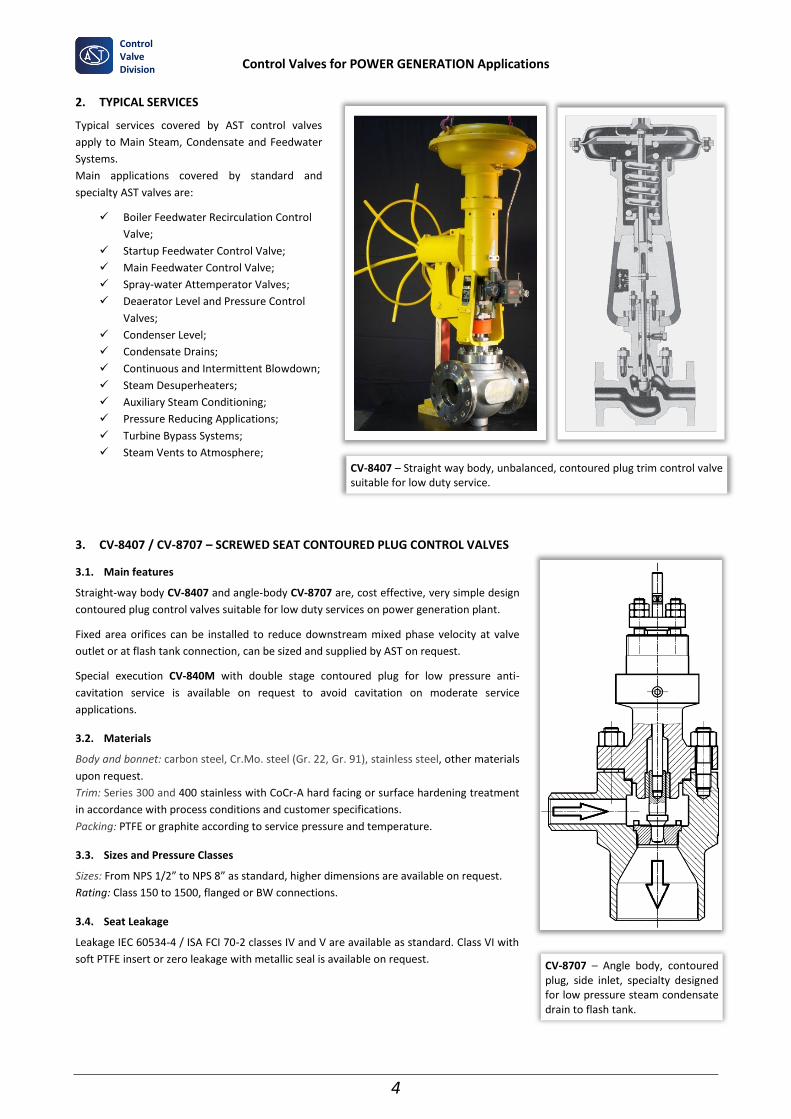
CV-8407 – Straight way body, unbalanced, contoured plug trim control valve suitable for low duty service.
CV-8707 – Angle body, contoured plug, side inlet, specialty designed for low pressure steam condensate drain to flash tank.
Control Valves for POWER GENERATION Applications
5
Control Valve Division
4. CV-8450 – GLOBE QUICK CHANGE CAGE VALVE
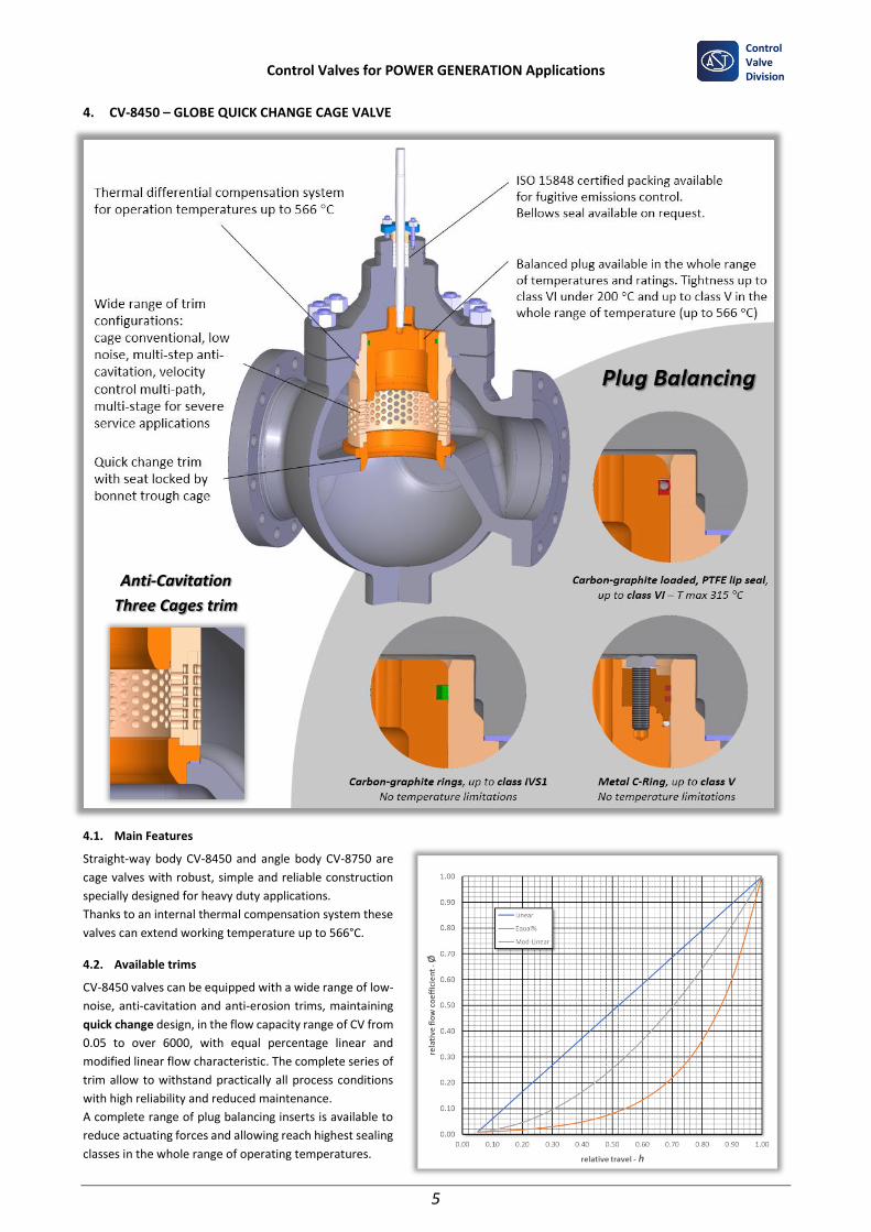
4.1. Main Features
Straight-way body CV-8450 and angle body CV-8750 are
cage valves with robust, simple and reliable construction
specially designed for heavy duty applications.
Thanks to an internal thermal compensation system these
valves can extend working temperature up to 566°C.
4.2. Available trims
CV-8450 valves can be equipped with a wide range of low-
noise, anti-cavitation and anti-erosion trims, maintaining
quick change design, in the flow capacity range of CV from
0.05 to over 6000, with equal percentage linear and
modified linear flow characteristic. The complete series of
trim allow to withstand practically all process conditions
with high reliability and reduced maintenance.
A complete range of plug balancing inserts is available to
reduce actuating forces and allowing reach highest sealing
classes in the whole range of operating temperatures.
Anti-Cavitation
Three Cages trim
Control Valves for POWER GENERATION Applications
6
Control Valve Division
4.3. Materials
Body and bonnet: carbon steel, Cr.Mo. steel (Gr. 22, Gr. 91), stainless steel, other materials upon request.
Plug: Series 300 stainless steel or 13-4 Cr steel with surface hardening treatment up to over 1100 HV, with CoCr-A hard facing on
sealing surfaces according to process conditions.
Seat: Series 400 hardened stainless steel or AISI 316 with CoCr-A hard facing.
Cage: Series 300 Cr plated stainless steel or 13-4 Cr steel with surface hardening treatment up to over 1100 HV.
VeCo-LT: AISI 300 or 400 stainless steel sheets, solid Inconel 718 by additive manufacturing for small trims with micro labyrinths.
Packing: PTFE or graphite according to service pressure and temperature.
4.4. Sizes and Pressure Classes
Size: From NPS 3/4” to NPS 24” as standard, higher dimensions are available on request.
Rating: Class 150 to 2500, flanged or BW connections.
4.5. Seat leakage IEC 60534-4 / ISA FCI 70-2
Classes IV and V are available as standard in the whole range of temperature with balanced plug.
Class VI with PTFE insert is available up to 200 °C.
Balanced trim with pilot plug (CV-8054) is available for high temperature steam service applications, when zero leakage is required.
4.6. Low-noise, anti-cavitation and anti-erosion special
trims details
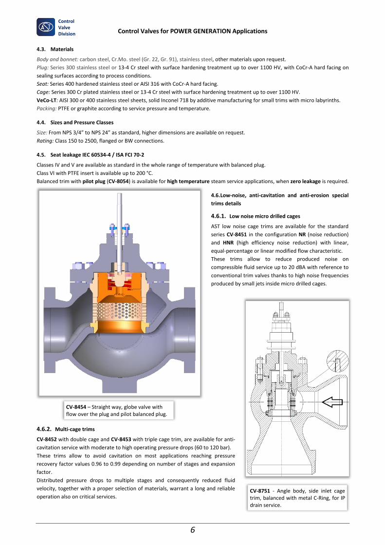
4.6.1. Low noise micro drilled cages
AST low noise cage trims are available for the standard
series CV-8451 in the configuration NR (noise reduction)
and HNR (high efficiency noise reduction) with linear,
equal-percentage or linear modified flow characteristic.
These trims allow to reduce produced noise on
compressible fluid service up to 20 dBA with reference to
conventional trim valves thanks to high noise frequencies
produced by small jets inside micro drilled cages.
4.6.2. Multi-cage trims
CV-8452 with double cage and CV-8453 with triple cage trim, are available for anti-
cavitation service with moderate to high operating pressure drops (60 to 120 bar).
These trims allow to avoid cavitation on most applications reaching pressure
recovery factor values 0.96 to 0.99 depending on number of stages and expansion
factor.
Distributed pressure drops to multiple stages and consequently reduced fluid
velocity, together with a proper selection of materials, warrant a long and reliable
operation also on critical services.
CV-8751 - Angle body, side inlet cage trim, balanced with metal C-Ring, for IP drain service.
CV-8454 – Straight way, globe valve with flow over the plug and pilot balanced plug.
Control Valves for POWER GENERATION Applications
7
Control Valve Division
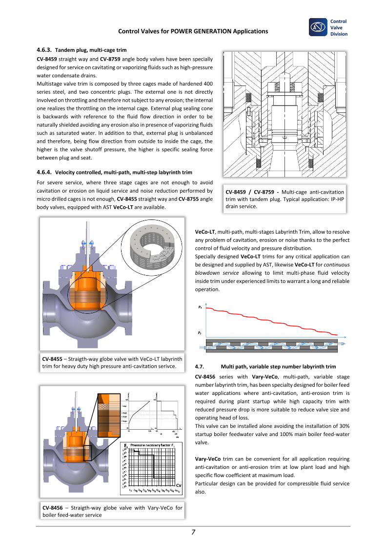
4.6.3. Tandem plug, multi-cage trim
CV-8459 straight way and CV-8759 angle body valves have been specially
designed for service on cavitating or vaporizing fluids such as high-pressure
water condensate drains.
Multistage valve trim is composed by three cages made of hardened 400
series steel, and two concentric plugs. The external one is not directly
involved on throttling and therefore not subject to any erosion; the internal
one realizes the throttling on the internal cage. External plug sealing cone
is backwards with reference to the fluid flow direction in order to be
naturally shielded avoiding any erosion also in presence of vaporizing fluids
such as saturated water. In addition to that, external plug is unbalanced
and therefore, being flow direction from outside to inside the cage, the
higher is the valve shutoff pressure, the higher is specific sealing force
between plug and seat.
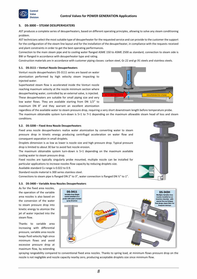
4.6.4. Velocity controlled, multi-path, multi-step labyrinth trim
For severe service, where three stage cages are not enough to avoid
cavitation or erosion on liquid service and noise reduction performed by
micro drilled cages is not enough, CV-8455 straight way and CV-8755 angle
body valves, equipped with AST VeCo-LT are available.
VeCo-LT, multi-path, multi-stages Labyrinth Trim, allow to resolve
any problem of cavitation, erosion or noise thanks to the perfect
control of fluid velocity and pressure distribution.
Specially designed VeCo-LT trims for any critical application can
be designed and supplied by AST, likewise VeCo-LT for continuous
blowdown service allowing to limit multi-phase fluid velocity
inside trim under experienced limits to warrant a long and reliable
operation.
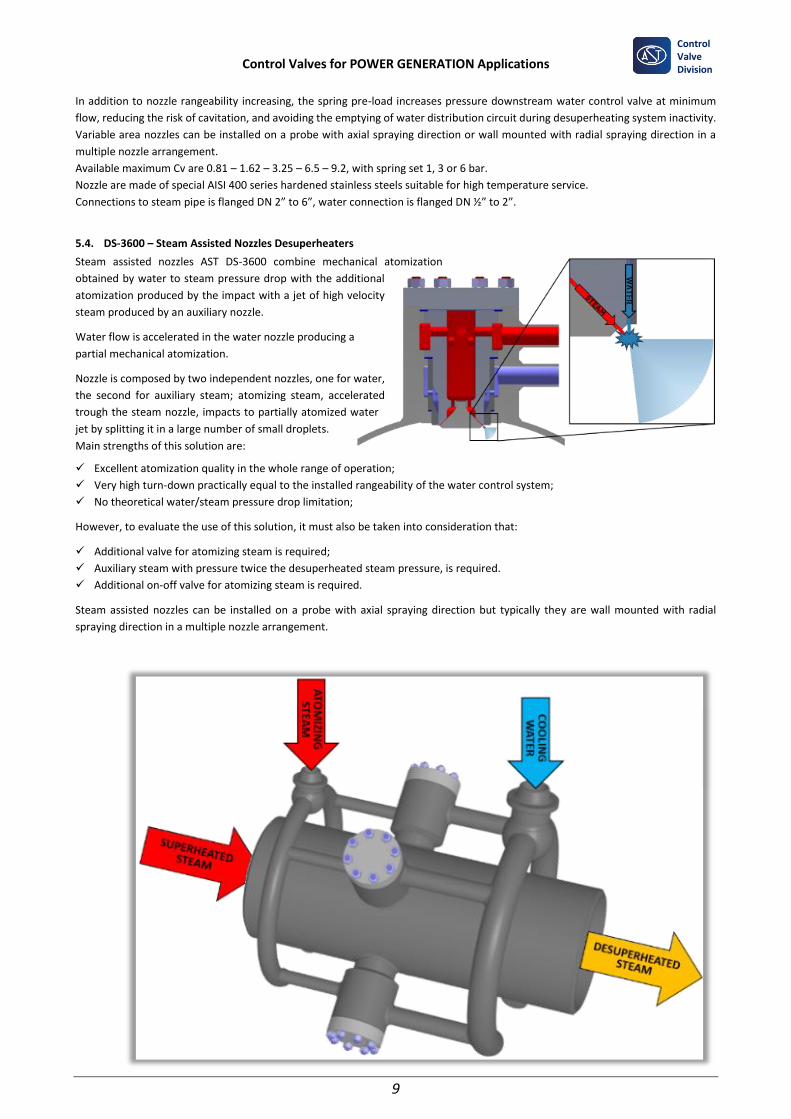
4.7. Multi path, variable step number labyrinth trim
CV-8456 series with Vary-VeCo, multi-path, variable stage
number labyrinth trim, has been specialty designed for boiler feed
water applications where anti-cavitation, anti-erosion trim is
required during plant startup while high capacity trim with
reduced pressure drop is more suitable to reduce valve size and
operating head of loss.
This valve can be installed alone avoiding the installation of 30%
startup boiler feedwater valve and 100% main boiler feed-water
valve.
Vary-VeCo trim can be convenient for all application requiring
anti-cavitation or anti-erosion trim at low plant load and high
specific flow coefficient at maximum load.
Particular design can be provided for compressible fluid service
also.
CV-8459 / CV-8759 - Multi-cage anti-cavitation trim with tandem plug. Typical application: IP-HP drain service.
CV-8455 – Straigth-way globe valve with VeCo-LT labyrinth trim for heavy duty high pressure anti-cavitation serivce.
CV-8456 – Straigth-way globe valve with Vary-VeCo for boiler feed-water service
Control Valves for POWER GENERATION Applications
8
Control Valve Division
5. DS-3000 – STEAM DESUPERHEATERS
AST produces a complete series of desuperheaters, based on different operating principles, allowing to solve any steam conditioning
problem.
AST technicians select the most suitable type of desuperheater for the requested service and can provide to the customer the support
for the configuration of the steam line layout and for the installation of the desuperheater, in compliance with the requests received
and plant constraints in order to get the best operating performances.
Connection to the main steam pipe and to cooling water flanged ASME 150 to ASME 2500 as standard, connection to steam side is
BW or flanged in accordance with desuperheater type and rating.
Construction materials are in accordance with customer piping classes: carbon steel, Gr.22 and gr.91 steels and stainless steels.
5.1. DS-3111 – Venturi Nozzle Desuperheaters
Venturi nozzle desuperheaters DS-3111 series are based on water
atomization performed by high velocity steam impacting to
injected water.
Superheated steam flow is accelerated inside the Venturi nozzle
reaching maximum velocity at the nozzle minimum section where
desuperheating water, controlled by an external valve, is injected.
These desuperheaters are suitable for small piping size and very
low water flows. They are available starting from DN 1/2” to
maximum DN 8” and they warrant an excellent atomization
regardless of the available water to steam pressure drop, requiring a very short downstream length before temperature probe.
The maximum obtainable system turn-down is 5÷1 to 7÷1 depending on the maximum allowable steam head of loss and steam
conditions.
5.2. DS-3200 – Fixed Area Nozzle Desuperheaters
Fixed area nozzle desuperheaters realize water atomization by converting water to steam
pressure drop in kinetic energy producing centrifugal acceleration on water flow and
consequent separation in small droplets.
Droplets dimension is as low as lower is nozzle size and high pressure drop. Typical pressure
drop is limited to about 30 bar to avoid fast nozzle erosion.
The maximum obtainable system turn-down is 5÷1 depending on the maximum available
cooling water to steam pressure drop.
Fixed nozzles are typically singularly probe mounted, multiple nozzle can be installed for
particular applications to increase nozzles flow capacity by reducing droplets size.
Available standard Cv range is 0.022 to 0.9.
Standard nozzle material is 300 series stainless steel.
Connections to steam pipe is flanged DN 2” to 3”, water connection is flanged DN ½” to 1”.
5.3. DS-3400 – Variable Area Nozzles Desuperheaters
As for the fixed area nozzles,
the operation of the variable
area nozzles is also based on
the conversion of the water
to steam pressure drop into
kinetic energy to atomize the
jet of water injected into the
steam flow.
Thanks to variable area
increasing with differential
pressure, variable area nozzle
keeps fluid velocity high since
minimum flows and avoid
excessive pressure drop at
maximum flow, by extending
spraying rangeability compared to conventional fixed area nozzles. Thanks to spring load, at minimum flows pressure drop on the
nozzle is not negligible and nozzle capacity nearby zero, producing acceptable droplets size since minimum flow.
WA
TER
SUPERHEATED STEAM DESUPERHEATED STEAM
Control Valves for POWER GENERATION Applications
9
Control Valve Division
In addition to nozzle rangeability increasing, the spring pre-load increases pressure downstream water control valve at minimum
flow, reducing the risk of cavitation, and avoiding the emptying of water distribution circuit during desuperheating system inactivity.
Variable area nozzles can be installed on a probe with axial spraying direction or wall mounted with radial spraying direction in a
multiple nozzle arrangement.
Available maximum Cv are 0.81 – 1.62 – 3.25 – 6.5 – 9.2, with spring set 1, 3 or 6 bar.
Nozzle are made of special AISI 400 series hardened stainless steels suitable for high temperature service.
Connections to steam pipe is flanged DN 2” to 6”, water connection is flanged DN ½” to 2”.
5.4. DS-3600 – Steam Assisted Nozzles Desuperheaters
Steam assisted nozzles AST DS-3600 combine mechanical atomization
obtained by water to steam pressure drop with the additional
atomization produced by the impact with a jet of high velocity
steam produced by an auxiliary nozzle.
Water flow is accelerated in the water nozzle producing a
partial mechanical atomization.
Nozzle is composed by two independent nozzles, one for water,
the second for auxiliary steam; atomizing steam, accelerated
trough the steam nozzle, impacts to partially atomized water
jet by splitting it in a large number of small droplets.
Main strengths of this solution are:
✓ Excellent atomization quality in the whole range of operation;
✓ Very high turn-down practically equal to the installed rangeability of the water control system;
✓ No theoretical water/steam pressure drop limitation;
However, to evaluate the use of this solution, it must also be taken into consideration that:
✓ Additional valve for atomizing steam is required;
✓ Auxiliary steam with pressure twice the desuperheated steam pressure, is required.
✓ Additional on-off valve for atomizing steam is required.
Steam assisted nozzles can be installed on a probe with axial spraying direction but typically they are wall mounted with radial
spraying direction in a multiple nozzle arrangement.
Control Valves for POWER GENERATION Applications
10
Control Valve Division
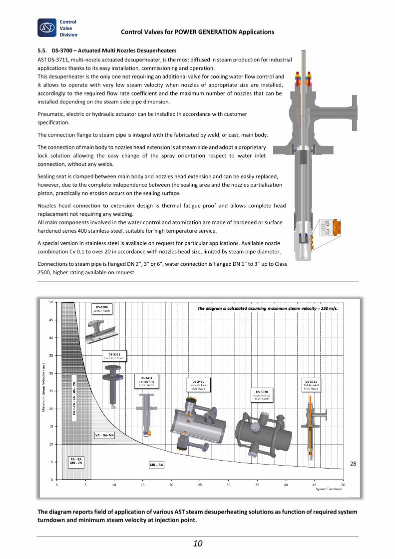
5.5. DS-3700 – Actuated Multi Nozzles Desuperheaters
AST DS-3711, multi-nozzle actuated desuperheater, is the most diffused in steam production for industrial
applications thanks to its easy installation, commissioning and operation.
This desuperheater is the only one not requiring an additional valve for cooling water flow control and
it allows to operate with very low steam velocity when nozzles of appropriate size are installed,
accordingly to the required flow rate coefficient and the maximum number of nozzles that can be
installed depending on the steam side pipe dimension.
Pneumatic, electric or hydraulic actuator can be installed in accordance with customer
specification.
The connection flange to steam pipe is integral with the fabricated by weld, or cast, main body.
The connection of main body to nozzles head extension is at steam side and adopt a proprietary
lock solution allowing the easy change of the spray orientation respect to water inlet
connection, without any welds.
Sealing seat is clamped between main body and nozzles head extension and can be easily replaced,
however, due to the complete independence between the sealing area and the nozzles partialization
piston, practically no erosion occurs on the sealing surface.
Nozzles head connection to extension design is thermal fatigue-proof and allows complete head
replacement not requiring any welding.
All main components involved in the water control and atomization are made of hardened or surface
hardened series 400 stainless-steel, suitable for high temperature service.
A special version in stainless steel is available on request for particular applications. Available nozzle
combination Cv 0.1 to over 20 in accordance with nozzles head size, limited by steam pipe diameter.
Connections to steam pipe is flanged DN 2”, 3” or 6”, water connection is flanged DN 1” to 3” up to Class
2500, higher rating available on request.
The diagram reports field of application of various AST steam desuperheating solutions as function of required system turndown and minimum steam velocity at injection point.
Control Valves for POWER GENERATION Applications
11
Control Valve Division
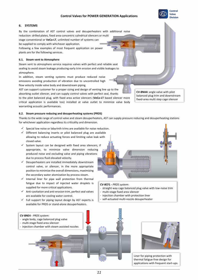
6. SYSTEMS
By the combination of AST control valves and desuperheaters with additional noise
reduction: drilled plates, fixed area concentric cylindrical silencers or multi
stage conventional or VeCo-LT, unlimited number of systems can
be supplied to comply with whichever application.
Following a few examples of most frequent application on power
plants are for the following services.
6.1. Steam vent to Atmosphere
Steam vent to atmosphere service requires valves with perfect and reliable seat
sealing to avoid steam leakage producing early trim erosion and visible leakages to
atmosphere.
In addition, steam venting systems must produce reduced noise
emissions avoiding production of vibration due to uncontrolled high
flow velocity inside valve body and downstream piping.
AST can support customer for a proper sizing and design of venting line up to the
absorbing outlet silencer, and can supply control valves with perfect seal, thanks
to the pilot balanced plug, with fixed area active silencers (VeCo-LT based silencer more
critical application is available too) installed at valve outlet to minimize valve body
warranting acoustic performances.
6.2. Steam pressure reducing and desuperheating systems (PRDS)
Thanks to the wide range of control valve and steam desuperheaters, AST can supply pressure reducing and desuperheating stations
for whichever application regardless its criticality and dimension.
✓ Special low noise or labyrinth trims are available for noise reduction.
✓ Different balancing inserts or pilot balanced plug are available
allowing to reduce actuating forces and limiting valve leak with
closed valve.
✓ System layout can be designed with fixed area silencers, if
appropriate, to minimize valve dimension reducing
produced noise and excluding valve and piping vibrations
due to process fluid elevated velocity.
✓ Desuperheaters are installed immediately downstream
control valve, or silencer, in the more appropriate
position to minimize the overall dimensions, maximizing
the secondary water atomization by process steam.
✓ Internal liner for pipe wall protection from thermal
fatigue due to impact of injected water droplets is
supplied for more critical applications.
✓ Anti-cavitation and anti-erosion trim, perfect seal valves
are available for cooling water control.
✓ Full support for piping layout design by AST experts is
available for PRDS or stand-alone desuperheaters.
CV-8NA4: angle valve with pilot balanced plug trim and downstream fixed-area multi step cage silencer
Liner for piping protection with thermal fatigue-free design for applications with frequent start-ups.
CV-8CF1 - PRDS system: - straight-way cage balanced plug valve with low-noise trim - multi-stage fixed area silencer - injection chamber with protection liner - self-actuated multi-nozzle desuperheater
CO
OLIN
G W
ATER
ATO
MIZIN
G S
TEAM
CV-8NE4 - PRDS system: - angle body, cage balanced plug valve - multi-stage fixed area silencer - injection chamber with steam assisted nozzles
Control Valves for POWER GENERATION Applications
12
Control Valve Division
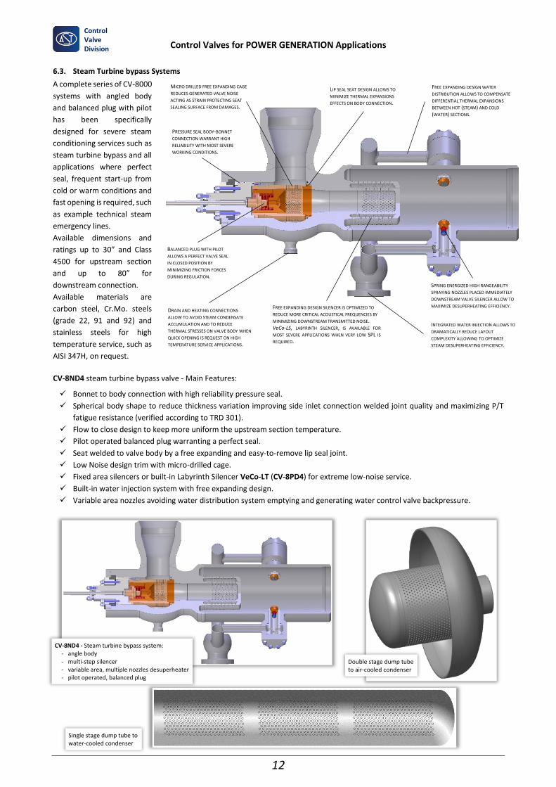
6.3. Steam Turbine bypass Systems
A complete series of CV-8000
systems with angled body
and balanced plug with pilot
has been specifically
designed for severe steam
conditioning services such as
steam turbine bypass and all
applications where perfect
seal, frequent start-up from
cold or warm conditions and
fast opening is required, such
as example technical steam
emergency lines.
Available dimensions and
ratings up to 30” and Class
4500 for upstream section
and up to 80” for
downstream connection.
Available materials are
carbon steel, Cr.Mo. steels
(grade 22, 91 and 92) and
stainless steels for high
temperature service, such as
AISI 347H, on request.
CV-8ND4 steam turbine bypass valve - Main Features:
✓ Bonnet to body connection with high reliability pressure seal.
✓ Spherical body shape to reduce thickness variation improving side inlet connection welded joint quality and maximizing P/T
fatigue resistance (verified according to TRD 301).
✓ Flow to close design to keep more uniform the upstream section temperature.
✓ Pilot operated balanced plug warranting a perfect seal.
✓ Seat welded to valve body by a free expanding and easy-to-remove lip seal joint.
✓ Low Noise design trim with micro-drilled cage.
✓ Fixed area silencers or built-in Labyrinth Silencer VeCo-LT (CV-8PD4) for extreme low-noise service.
✓ Built-in water injection system with free expanding design.
✓ Variable area nozzles avoiding water distribution system emptying and generating water control valve backpressure.
PRESSURE SEAL BODY-BONNET
CONNECTION WARRANT HIGH
RELIABILITY WITH MOST SEVERE
WORKING CONDITIONS.
FREE EXPANDING DESIGN WATER
DISTRIBUTION ALLOWS TO COMPENSATE
DIFFERENTIAL THERMAL EXPANSIONS
BETWEEN HOT (STEAM) AND COLD
(WATER) SECTIONS.
BALANCED PLUG WITH PILOT
ALLOWS A PERFECT VALVE SEAL
IN CLOSED POSITION BY
MINIMIZING FRICTION FORCES
DURING REGULATION.
MICRO DRILLED FREE EXPANDING CAGE
REDUCES GENERATED VALVE NOISE
ACTING AS STRAIN PROTECTING SEAT
SEALING SURFACE FROM DAMAGES.
SPRING ENERGIZED HIGH RANGEABILITY
SPRAYING NOZZLES PLACED IMMEDIATELY
DOWNSTREAM VALVE SILENCER ALLOW TO
MAXIMIZE DESUPERHEATING EFFICIENCY. DRAIN AND HEATING CONNECTIONS
ALLOW TO AVOID STEAM CONDENSATE
ACCUMULATION AND TO REDUCE
THERMAL STRESSES ON VALVE BODY WHEN
QUICK OPENING IS REQUEST ON HIGH
TEMPERATURE SERVICE APPLICATIONS.
LIP SEAL SEAT DESIGN ALLOWS TO
MINIMIZE THERMAL EXPANSIONS
EFFECTS ON BODY CONNECTION.
FREE EXPANDING DESIGN SILENCER IS OPTIMIZED TO
REDUCE MORE CRITICAL ACOUSTICAL FREQUENCIES BY
MINIMIZING DOWNSTREAM TRANSMITTED NOISE. VeCo-LS, LABYRINTH SILENCER, IS AVAILABLE FOR
MOST SEVERE APPLICATIONS WHEN VERY LOW SPL IS
REQUIRED.
INTEGRATED WATER INJECTION ALLOWS TO
DRAMATICALLY REDUCE LAYOUT
COMPLEXITY ALLOWING TO OPTIMIZE
STEAM DESUPERHEATING EFFICIENCY.
CV-8ND4 - Steam turbine bypass system: - angle body - multi-step silencer - variable area, multiple nozzles desuperheater - pilot operated, balanced plug
Double stage dump tube to air-cooled condenser
Single stage dump tube to water-cooled condenser
Control Valves for POWER GENERATION Applications
13
Control Valve Division
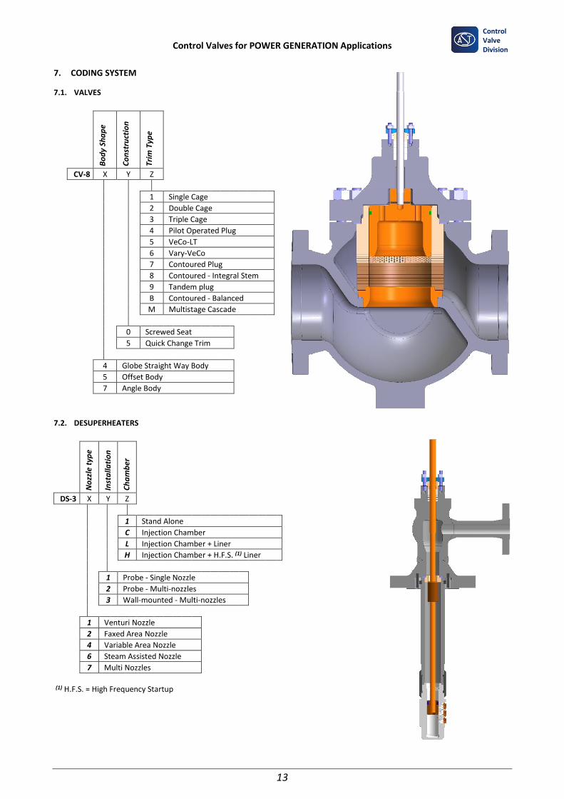
7. CODING SYSTEM
7.1. VALVES
Bo
dy
Sha
pe
Co
nst
ruct
ion
Tri
m T
ype
CV-8 X Y Z
1 Single Cage 2 Double Cage 3 Triple Cage 4 Pilot Operated Plug 5 VeCo-LT 6 Vary-VeCo 7 Contoured Plug 8 Contoured - Integral Stem 9 Tandem plug B Contoured - Balanced M Multistage Cascade
0 Screwed Seat
5 Quick Change Trim
4 Globe Straight Way Body
5 Offset Body
7 Angle Body
7.2. DESUPERHEATERS
No
zzle
typ
e
Inst
alla
tio
n
Ch
am
ber
DS-3 X Y Z
1 Stand Alone
C Injection Chamber
L Injection Chamber + Liner
H Injection Chamber + H.F.S. (1) Liner
1 Probe - Single Nozzle
2 Probe - Multi-nozzles
3 Wall-mounted - Multi-nozzles
1 Venturi Nozzle
2 Faxed Area Nozzle
4 Variable Area Nozzle
6 Steam Assisted Nozzle
7 Multi Nozzles
(1) H.F.S. = High Frequency Startup

Control Valves for POWER GENERATION Applications
14
Control Valve Division
7.3. SYSTEMS
Sile
nce
r St
ag
es
Des
up
erh
eate
r
Tri
m T
ype
CV-8 X Y Z
1 1 Cage 2 2 Cages 3 3 Cages 4 Pilot Balanced Plug 5 VeCo-LT 6 Vary-VeCo 7 Contoured Plug 8 Contoured - Integral Stem 9 Tandem Plug B Contoured - Balanced M Multi-stage Cascade
A None B Probe - Fixed Area Nozzle C Probe - Variable Area Nozzle D Wall Mounted - Multi-nozzle E Steam Assisted Nozzles G Venturi Nozzle H Internal Injection
Stra
igh
t B
od
y
Ba
sed
on
CV
-84
00
Off
set
Bo
dy
Ba
sed
on
CV
-85
00
An
gle
Bo
dy
Ba
sed
on
CV
-87
00
Nr. of STAGES
A E L None B F M 1 Stage C G N Multi Stage D H P VeCo-LS
8. OPTIONS
- Devices for line blowing and washing with installed valves.
- Devices for lines hydro-testing with assembled valves.
- Special tools for assembling/disassembling valves on field.
9. ACCESSORIES
- Pneumatic, electropneumatic or digital positioners.
- Remote position feedback configuration for heavy duty services.
- Air set.
- Flow boosters.
- Lockup valves.
- Solenoid valves for fast strokes and for valve action to fail position.
- Mechanical stroke limiters.
- Hydraulic manual operator.
Control Valves for POWER GENERATION Applications
15
Control Valve Division
Control Valves for POWER GENERATION Applications
16
Control Valve Division
10/2019