Embed Size (px)
Citation preview

1
Fundamentals ofControl ValveEngineering
Prepared By:Mohammad Pourzahed
2
Table of Contents
n Section 1: Control valve
* Definitions* Types of control valves* Balance or unbalance * Data needed for control valve selection* Valve Characteristics * Valve body materials * Types of bonnet * Type of packing

3
n Section 2: Actuators
* Types of actuator * Actuator sizing
n Section 3: Positioners
* Positioners * Accessories

4
n Section 4: Server Service
* Noise * Cavitation * Flashing * Choked Flow

5
n Section 5: Server Service Treatments
* Source and path treatments * Special cages * Proper material selection
n Section 6: Standards
n Section 7: Sample Specification
n Section 8: Sample Datasheet

6
Section 1
Control valve

7
Table of Contents
* Definitions* Types of control valves* Balance or unbalance * Data needed for control valve selection* Valve Characteristics * Valve body materials * Types of bonnet * Type of packing
8
Definitions
n What Is A Control Valve?
The most common final control element in the process control industries is the control valve. The control valve manipulates a flowing fluid, such as gas, steam, water, or chemical compounds, to compensate for the load disturbance and keep the regulated process variable as close as possible to the desired set point.
The control valve assembly typically consists of the valve body, the internal trim parts, an actuator to provide the motive power to operate the valve, and a variety of additional valve accessories, which can include positioners, transducers, supply pressure regulators, manual operators, snubbers, or limit switches.

9
n Actuator:A pneumatic, hydraulic, or electrically powered device that supplies force
and motion to open or close a valve.
n Accessory: A device that is mounted on the actuator to complement the actuator’s
function and make it a complete operating unit. Examples include positioners, supply pressure regulators, solenoids, and limit switches.
n Capacity (Valve):The rate of flow through a valve under stated conditions.
n I/P: Shorthand for current-to-pres-sure (I-to-P). Typically applied to input
transducer modules.

10
n Positioner:A position controller (servomechanism) that is mechanically connected to a
moving part of a final control element or its actuator and that automatically adjusts its output to the actuator to maintain a desired position in proportion to the input signal.
n Travel:The movement of the closure member from the closed position to an
intermediate or rated full open position.
n Trim:The internal components of a valve that modulate the flow of the controlled
fluid.

11
n Bonnet:The portion of the valve that contains the packing box and stem seal and can
guide the stem. It provides the principal opening to the body cavity for assembly of internal parts or it can be an integral part of the valve body. It can also provide for the attachment of the actuator to the valve body. Typical bonnets are bolted, threaded, welded, pressure-seals, or integral with the body. (This term is often used in referring to the bonnet and its included packing parts. More properly, this group of component parts should be called the bonnet assembly.)
n Seat:The area of contact between the closure member and its mating surface that
establishes valve shut-off.

12
n Cage: A part of a valve trim that surrounds the closure member and can provide flow
characterization and/or a seating surface. It also provides stability, guiding, balance, and alignment, and facilitates assembly of other parts of the valve trim. The walls of the cage contain openings that usually determine the flow characteristic of the control valve.
n Port:The flow control orifice of a control valve.
n Packing:A part of the valve assembly used to seal against leakage around the valve
disk or stem.

13
n Seat Ring:A part of the valve body assembly that provides a seating surface for the
closure member and can provide part of the flow control orifice.
n Valve Stem: In a linear motion valve, the part that connects the actuator stem with the
closure member.
n Yoke:The structure that rigidly connects the actuator power unit to the valve.
14
n Fail-Closed:A condition wherein the valve closure member moves to a closed position
when the actuating energy source fails.
n Fail-Open: A condition wherein the valve closure member moves to an open position
when the actuating energy source fails.
n Fail-Safe:A characteristic of a valve and its actuator, which upon loss of actuating
energy supply, will cause a valve closure member to be fully closed, fully open, or remain in the last position, whichever position is de-fined as necessary to protect the process. Fail-safe action can involve the use of auxiliary controls connected to the actuator.
15
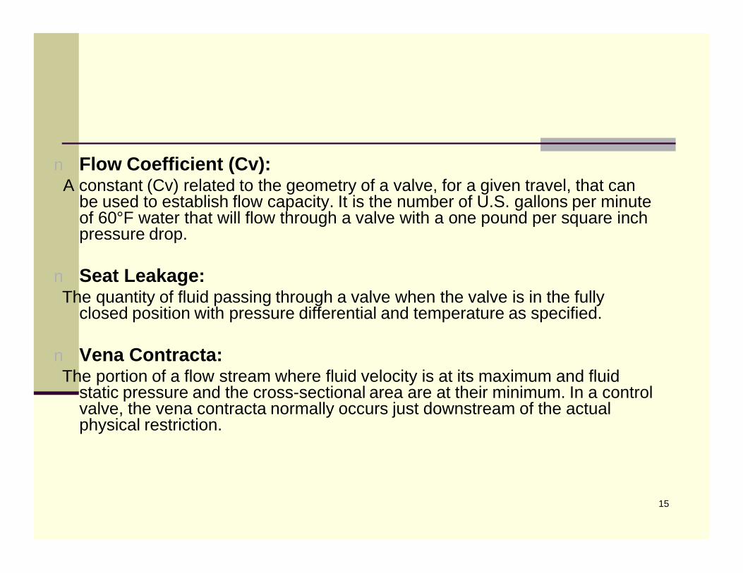
n Flow Coefficient (Cv):A constant (Cv) related to the geometry of a valve, for a given travel, that can
be used to establish flow capacity. It is the number of U.S. gallons per minute of 60°F water that will flow through a valve with a one pound per square inch pressure drop.
n Seat Leakage: The quantity of fluid passing through a valve when the valve is in the fully
closed position with pressure differential and temperature as specified.
n Vena Contracta:The portion of a flow stream where fluid velocity is at its maximum and fluid
static pressure and the cross-sectional area are at their minimum. In a control valve, the vena contracta normally occurs just downstream of the actual physical restriction.

16
n Feedback Signal: The return signal that results from a measurement of the directly controlled
variable. For a control valve with a positioner, the re-turn signal is usually a mechanical indication of closure member stem position that is fed back into the positioner.
n Supply Pressure: The pressure at the supply port of a device. Common values of control valve
supply pres-sure are 20 psig for a 3 to 15 psig range and 35 psig for a 6 to 30 psig range.

17
Types of control valves
n Globe Valves
n Ball Valves
n Butterfly Valves
n Eccentric Disk

18
Globe valves
n Size Limitation
n Lower Capacity than Ball or Butterfly
n Overall expensive specially in large sizes
n Tight shutoff in small sizes

19

20

21
Ball Valves
n Classified as High-Recovery Valves
n Limited in allowable pressure drop and temperature than globe valves
n Good shutoff capabilities
n Almost ½ price of globe valves

22

23
24
Butterfly Valves
n Most Economical valve on a cost per flow capacity basis
n Fully lined valves bore can provide tight shutoff
n Low cost body material for corrosive fluid due to lined body bore
n Handling of high inlet pressure and pressure drop

25
26
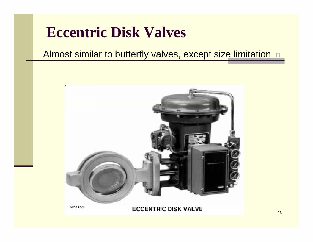
Eccentric Disk ValvesnAlmost similar to butterfly valves, except size limitation

27
Balance plug Style Valve Bodies
n Single ported that only one seat ring is usedn High capacityn High capacityn Large sizesn Smaller actuator sizesn Cage style allows ease of reducing trim,
characteristic changen Unbalance is double ported

28
Data needed for Control Valve Selectionn Type of fluidn Temperature of fluidn Flow rate of fluidn Viscosity of fluidn Specific Gravity of fluidn Inlet pressure (Upstream)n Outlet pressure (Downstream)n Delta P shutoff for actuator sizingn Pipe size/Schedule

29
Data needed for Control Valve Selection
n Valve typen Body materialn End connection type (Flanged or Screwed)n Valve Action (F.C. or F.O)n Type of Actuatorn Instrument Air Supply Pressuren Accessories/Positioners/Etc.

30
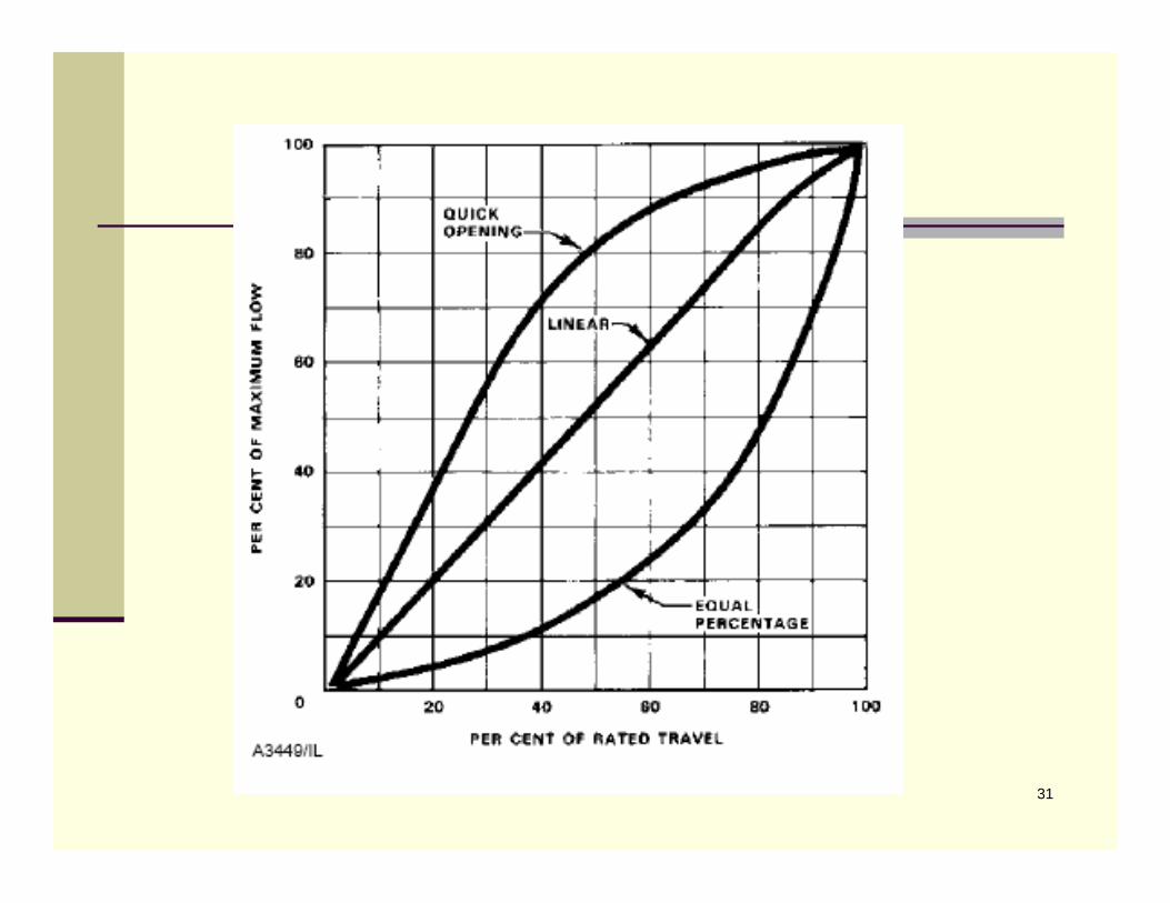
Valve Characteristics
n The flow characteristic of a control valve is the relationship between flow rate through the valve and valve travel as the travel is varied from 0-100%
n Typical valve characteristics conducted in this manner are named Linear, Equal-Percentage, and Quick Opening
31

32
Characterized Cages for Globe-Style Valve Bodies

33
Valve Body Material
n Valve body material selection is usually based on the Pressure, Temperature, Corrosive properties and Erosive Properties of the flow media.
n Cast carbon steel (ASTM A216-Grade WCB) is the most popular steel for valve bodies in moderate service such as Air, superheat or saturated steam, non corrosive fluids.
n Cast Chrome-Moly Steel (ASTM A217-Grade WCB-C9) has addition of chromium/Molybdenum that provide corrosion resistance and also is suitable for temperature up to 1050 Deg.F.

34
n Cast type 304 SST (ASTM A351-Grade CF8) is for oxidizing and very corrosive fluids.
n Cast type 316 SST (ASTM A351-Grade CF8M) is same as 304 SST but since it has addition of Molybdenum then better resistance to corrosion.
n Cast Iron (ASTM A126) is used for steam. Water. Gas and non corrosive fluids and is inexpensive.
n Cast Bronze (ASTM B61& ASTM B62) is used for steam, Air, Water, Oil and non corrosive fluids.

35
Type of Bonnet
n Standard Bonnet
n Extension BonnetAre used for high and low temperature service to protect packing from extreme temperature.
n Bellows Seal Bonnets Are used when no leakage are allowed, Toxic fluids,
Volatile, Radioactive or highly expensive fluids.

36

37
Type of Packing
PTFE Type
n Standard TFE up to 232 Deg. C.n Supercedes old TFE/ASB. Which is obsoleted for health reasonn Minimizes friction, so may require smaller Actuatorn Good resistivity to most known chemicalsn No lubrication required

38
Graphite Type
n High temperature service up to 1200 Deg.F.n Leak freen No lubrication required

39
Section 2
Actuators

40
Table of Contents
* Types of actuator
* Actuator sizing

41
Types of actuator
n Pneumatically operated control valve actuators are the most popular type in use, but electric, hydraulic, and manualactuators are also widely used. The spring and diaphragmpneumatic actuator is most commonly specified due to its dependability and simplicity of design. Pneumatically operated piston actuators provide high stem force out-put for demanding service conditions. Adaptations of both spring-and-diaphragm and pneumatic piston actuators are available for direct installation on rotary-shaft control valves.

42
n Electric and electro-hydraulic actuators are more complex and more ex-pensive than pneumatic actuators. They offer advantages where no air supply source is available, where low ambient temperatures could freeze condensed water in pneumatic supply lines, or where unusually large stem forces are needed. A summary follows, discussing the design and characteristics of popular actuator styles.

43

44

45
Diaphragm Actuators
n Pneumatically operated diaphragm actuators use air supply from controller, positioner, or other source.
n Various styles include: direct-acting (increasing air pressure pushes down diaphragm and extends actuator stem); reverse-acting (in-creasing air pressure pushes up diaphragm and retracts actuator stem); reversible (actuators that can be assembled for either direct or reverse action); direct-acting unit for rotary valves (increasing air pressure pushes down on diaphragm, which may either open or close the valve, depending on orientation of the actuator lever on the valve shaft).

46
n Net output thrust is the difference between diaphragm force and opposing spring force.
n Molded diaphragms provide linear performance and increased travels.
n Output thrust required and supply air pressure available dictate size.
n Diaphragm actuators are simple, dependable, and economical.

47
Piston Actuators
n Piston actuators are pneumatically operated using high-pressure plant air to 150 psig, often eliminating the need for supply pressure regulator.
n Piston actuators furnish maximum thrust output and fast stroking speeds.
n Piston actuators are double acting to give maximum force in both directions, or spring return to provide fail-open or fail-closed operation.
n Various accessories can be incorporated to position a double-acting piston in the event of supply pressure failure. These include pneumatic trip valves and lock-up systems.

48
n Also available are hydraulic snubbers, hand wheels and units without yokes, which can be used to operate butterfly valves, louvers, and similar industrial equipment.
n Other versions for service on rotary-shaft control valves include a sliding seal in the lower end of the cylinder. This permits the actuator stem to move laterally as well as up and down without leakage of cylinder pres-sure. This feature permits direct connection of the actuator stem to the actuator lever mounted on the rotary valve shaft, thereby eliminating one joint or source of lost motion.

49
Electro-hydraulic Actuators
n Electro-hydraulic actuators require only electrical power to the motor and an electrical input signal from the controller.
n Electro-hydraulic actuators are ideal for isolated locations where pneumatic supply pressure is not available but where precise control of valve plug position is needed.
n Units are normally reversible by making minor adjustments and might be self-contained, including motor, pump, and double-acting hydraulically operated piston within a weather proofor explosion-proof casing.

50

51
Manual Actuators
n Manual actuators are useful where automatic control is not required, but where ease of operation and good manual control is still necessary . They are often used to actuate the bypass valve in a three-valve bypass loop around control valves for manual control of the process during maintenance or shut down of the automatic system.
n Manual actuators are available in various sizes for both globe style valves and rotary-shaft valves.
n Dial-indicating devices are available for some models to permit accurate repositioning of the valve plug or disk.
n Manual actuators are much less expensive than automatic actuators.

52

53
Electric Actuators
n Traditional electric actuator designs use an electric motor and some form of gear reduction to move the valve. Through adaptation, these mechanisms have been used for continuous control with varying degrees of success. To date, electric actuators have been much more expensive than pneumatic for the same performance levels. This is an area of rapid technological change, and future designs may cause a shift towards greater use of electric actuators.
54
Actuator sizing
n Actuators are selected by matching the force required to stroke the valve with an actuator that can supply that force. For rotary valves a similar process matches the torque required to stroke the valve with an actuator that will supply that torque. The same fundamental process is used for pneumatic, electric, and electro-hydraulic actuators.

55
The force required to operate a globe valve includes:
n Force to overcome static unbalance of the valve plug
n Force to provide a seat load
n Force to overcome packing friction
n Additional forces required for certain specific applications or constructions

56
Section 3
Positioners

57
Table of Contents
* Positioners
* Accessories

58
PositionersPneumatically operated valves depend on a positioner
to take an input signal from a process controller and convert it to valve travel. These instruments are available in three configurations:
1. Pneumatic Positioners—A pneumatic signal (usually 3-15 psig) is supplied to the positioner. The positioner translates this to a required valve position and supplies the valve actuator with the required air pressure to move the valve to the correct position.
2. Analog I/P Positioner—This positioner performs the same function as the one above, but uses electrical current (usually 4-20 mA) instead of air as the input signal.

59
3. Digital Controller—Although this instrument functions very much as the Analog I/P described above, it differs in that the electronic signal conversion is digital rather than analog. The digital products cover three categories.
n Digital Non-Communicating—A current signal (4-20 mA) is supplied to the positioner, which both powers the electronics and controls the output.
n HART—This is the same as the digital non-communicating but is also capable of two-way digital communication over the same wires used for the analog signal.
n Fieldbus—This type receives digitally based signals and positions the valve using digital electronic circuitry coupled to mechanical components.

60

61
Why We install Positioner?
n For Fast operation
n Due to packing friction
n Long Travel valves
n Big Actuators
n Better Accuracy
n Split Range Applications

62
Accessoriesn Limit Switches
n Solenoid Valve Manifold
n Supply Pressure Regulator
n Pneumatic Lock-Up Systems
n Electro-Pneumatic Transducers

63
Section 4
Sever Service

64
Table of Contents
* Noise * Cavitation * Flashing * choked flow

65
Noise
Source of Valve Noise
n Mechanical Vibration of valve component
n Hydrodynamic Noise
n Aerodynamic Noise

66
Types of Control Valve Noise
n Mechanical Vibration Noisen Plug Instability Noisen Resonant Noisen Lateral movement of plugn Frequencies less than
1500Hz
l Aerodynamic Noise– Highest energy components
are in audible range– Turbulence of flow– Flow path, obstructions, rapid
expansion, deceleration, and direction changes
– Frequencies typical 500 to 8000 Hz
Generation
Propagation
RadiationCoupling
turb
ObstructionsTo Flow Changes In
Flow Direction
ExpansionArea
67
Mechanical Damage
n High noise levels can cause pipe vibrationn Damage to downstream equipment
n Noise above 110 dBA can destroy a valve very quickly

68
Cavitation and Flashingn The IEC liquid sizing standard calculates an allowable sizing
pressure drop, DPmax. If the actual pressure drop across the valve, as defined by the system conditions of P1 and P2, is greater than DPmax then either flash-ing or cavitation may occur. Structural damage to the valve and adjacent piping may also result.
n If pressure at the vena contracta should drop below the vapor pressure of the fluid (due to increased fluid velocity at this point) bubbles will form in the flow stream. Formation of bubbles will increase greatly as vena contracta pressure drops further be-low the vapor pressure of the liquid. At this stage, there is no difference be-tween flashing and cavitation, but the potential for structural damage to the valve definitely exists.

69
Cavitation and Flashingn If pressure at the valve outlet remains below the
vapor pressure of the liquid, the bubbles will remain in the down stream system and the process is said to have flashed. Flashing can produce serious erosion damage to the valve trim parts and is characterized by a smooth, polished appearance of the eroded surface. Flashing damage is normally greatest at the point of highest velocity, which is usually at or near the seat line of the valve plug and seat ring.
n On the other hand, if down stream pressure recovery is sufficient to raise the outlet pressure above the vapor pressure of the liquid, the bubbles will collapse, or implode, producing cavitation.

70
Cavitation and Flashing
n Collapsing of the vapor bubbles releases energy and produces a noise similar to what one would expect if gravel were flowing through the valve. If the bubbles collapse in close proximity to solid surfaces in the valve, the energy released will gradually tear away the material leaving a rough, cinder like surface. Cavitation damage may extend to the adjacent downstream pipe line, if that is where pressure recovery occurs and the bubbles collapse. Obviously, high recovery valves tend to be more subject to cavitation, since the downstream pressure is more likely to rise above the liquid’s vapor pressure.

71
Pressure
Cavitation
Vena Contracta
VapourPressure
Vapour Bubbles Form Vapour Bubbles Collapse

72
Cavitation Damage
n
cavillus
Cavitation Damage
Cavitation Damage

73
Valve style comparison
n Rotary Valvesn High Recoveryn Low Km (Fl2)n Pvena Contracta Very lown Not suited to high
pressure dropsn Bearings/shaft/Seals
n Attenuators give low level protection against cavitation
n Globe Valvesn Low recoveryn High Km (Fl2)n Pvena Contracta close to P2n Suited to very high pressure
dropsn Cage guided
n High technology multi stage anti-cavitation trims

74
Cavitation Damage
n

75
Pressure
Flashing
Vena Contracta
VapourPressure
Vapour Bubbles Form Mixture of vapour and liquid at outlet

76
Flashing Damage
n

77
choked flow
n The maximum or limiting flow rate (qmax), commonly called choked flow, is manifested by no additional in-crease in flow rate with increasing pressure differential with fixed up-stream conditions. In liquids, choking occurs as a result of vaporization of the liquid when the static pressure within the valve drops below the vapor pressure of the liquid.
n Choked Flow Causes Flashing and Cavitation.

78
Section 5
Server Service Treatments

79
Table of Contents
* Source and path treatments
* Special cages
* Proper material selection

80
n Noise reduction can be very expensiven Special trim n Larger valve size
n Examine specified noise levelsn are they really required
n location of valven valve operation§ When / duration / what else will be happening§ Typically Emergency Vent valves only operate over
short periods and a higher noise level is accepted
Noise Solutions

81
Noise Solutions
n Path treatmentn Treatment of the noise
after it is generated in the valve
n Heavy Walled Pipen Ensure correct diameter
and schedule are used
n Does schedule align with pressure rating?
n thermal or acoustic insulation
n Silencers
Noi
se A
ttenu
atio
n(d
B)
15
10
5
0 1 2Insulation Thickness(Inches)
Thermal
Acoustic20
Most steam valves are insulated so use it to
reduce price
1 2 3 443

82
Path Treatment
AcousticalInsulation(2’’ Thick)
96 dBa
Sound PressureLevels Outsideof 6 Inch Pipe
UntreatedPipe (SCH 40)
110 dBa
HeavyWalled PIpe(SCH 80)
106.3 dBa
UntreatedPipe (SCH 40)
110 dBa
Inline Silencer
85 dBa
UntreatedPipe (SCH 40)
85 dBa
90
100
110dBA

83
Noise Solutions
n Source Treatmentn Treatment of the noise at source
n Reduce the noise generatedn Change the properties of the noise generated
n Special valve trim
1. Determine stream power at the vena contracta
2. Convert to noise power at the valve outlet
3. Determine sound pressure level in the flow stream
4. Determine A-Weighted sound pressure level outside pipe wall
5. Translate sound pressure level to standard observer
location
IEC IEC 534534--88--3 3 5 5 step procedure for calculating valve noisestep procedure for calculating valve noise

85
Noise Attenuating Cages
n Slotted or Drilled Hole Cagesn Divide flow into smaller jetsn Prevent jets from combiningn Shift the noise frequency
outside audible rangen Examples
n WhisperFlo, Whisper III, and Whisper I

86
Inline Diffuser
P1 Pd P2
∆P1 ∆P2
∆P
A1753

87
Diffuser Sizing Objective
Valve LpA = 115 dBA
Valve LpA = 80 dBA Diffuser LpA = 80 dBA
A6347

88
Diffusers
P1
P2
Pd
Optimisation in program adjusts the Pd until the noise from the valve and diffuser are equal

89
Cavitation Solutions
n Path Treatmentn Treating the effects of cavitation
n Protecting exposed areas with hardened materials
n Selecting valve to direct the cavitation away from surfaces
n Source Treatmentn Treating the cause of cavitation

90
Cavitation - Path Treatment
n Select body style that directs the cavitation away from surfaces
n Angle body n Flow downn Liner n Hardened trimn Micro-Flat Trim for low Cv
requirementsn Cavitation is mainly confined to
the centre of the outlet passage

91
Cavitation - Path Treatment
n Aspirationn Inject air into cavitating
flow streamn Air bubbles absorb energy
released in bubble collapse

92
Cavitation - Source Treatmentn Treating the cause of cavitationn Use valve trim that avoids cavitation
n Low recovery valve § High FL
2( KM)§ Change from rotary valve to globe
PressureP1
PV
P2
High Recovery Valve FL2 = 0.5
Cavitation
Low Recovery Valve FL2 = 0.85
No Cavitation

93
Staged Pressure Drop
P1
P2PV
1st Stage 2nd Stage 3rd Stage
Standard Trim
Staged Trim

94
Section 6
Standards

95
REFERENCE CODES AND STANDARDSn Numerous standards are applicable to control valves. International and
global standards are becoming increasingly important for companies that participate in global markets. Following is a list of codes and standards that have been or will be important in the design and application of control valves.
American Petroleum Institute (API)
n Spec 6D, Specification for Pipelinen Valves (Gate, Plug, Ball, and Check Valves)n 598, Valve Inspection and Testingn 607, Fire Test for Soft-Seated Quarter-Turn Valvesn 609, Lug- and Wafer-Type Butterfly Valves

96
Iranian Petroleum Standard (IPS)& National Petrochemical Co. Standard (NPCS)
n IPS-E-IN-160,Engineering standard for Control Valves
n IPS-M-IN-160,Material standard for control valves
n IPS-C-IN-160,Construction and installation standard for Control Valves
n NPCS-MS-IN-23,M.S. for Control Valves
n NPCS-SD-IN-18,Air Connection for Control Valves

97
American Society of Mechanical Engineers (ASME)
n B16.1, Cast Iron Pipe Flanges and Flanged Fittingsn B16.4, Gray Iron Threaded Fittingsn B16.5, Pipe Flanges and Flanged Fittings (for steel, nickel-based
alloys, and other alloys)n B16.10, Face-to-Face and End-to-End Dimensions of Valves (see ISA
standards for dimensions for most control valves)n B16.24, Cast Copper Alloy Pipen B16.25, Butt welding Endsn Flanges and Flanged Fittingsn B16.34, Valves - Flanged, Threaded and Welding Endn B16.42, Ductile Iron Pipe Flanges and Flanged Fittingsn B16.47, Large Diameter Steel Flanges (NPS 26 through NPS 60)

98
Instrument Society of America (ISA)
n S51.1, Process Instrumentation Terminologyn S75.01, Flow Equations for Sizing Control Valvesn S75.02, Control Valve Capacity Test Proceduresn S75.03, Face-to-Face Dimensions for Flanged Globe-Style Control
Valve Bodies (Classes 125, 150, 250, 300 and 600)n S75.04, Face-to-Face Dimensions for Flangeless Control Valves
(Classes 150, 300, and 600)n S75.05, Terminologyn S75.07, Laboratory Measurement of Aerodynamic Noise Generated by
Control Valvesn S75.08, Installed Face-to-Face Dimensions for Flanged Clamp or Pinch
Valvesn S75.11, Inherent Flow Characteristic and Range ability of Control
Valves

99
n S75.12, Face-to-Face Dimensions for Socket Weld-End and crewed-End Globe-Style Control Valves (Classes 150, 300, 600, 900, 1500, and 2500)
n S75.13, Method of Evaluating the Performance of Positioners with Analog Input Signals
n S75.14, Face-to-Face Dimensions for Butt-weld-End Globe-Style Control Valves (Class 4500)
n S75.15, Face-to-Face Dimensions for Butt-weld-End Globe-Style Control Valves (Classes 150, 300, 600, 900,1500, and 2500)
n S75.16, Face-to-Face Dimensions for Flanged Globe-Style Control Valve Bodies (Classes 900, 1500, and 2500)
n S75.17, Control Valve Aerodynamic Noise Predictionn S75.19, Hydrostatic Testing of Control Valves

100
International Standards Organization (ISO)
n 5752, Metal valves for use in flanged pipe systems - Face-to-face and centre-to-face dimensions
n 7005-1, Metallic flanges - Part 1: Steel flanges
n 7005-2, Metallic flanges - Part 2: Cast iron flanges
n 7005-3, Metallic flanges - Part 3: Copper alloy and composite flanges
101
NACE International
n NACE MR0175/ISO 15156, Petroleum and Natural Gas Industries Materials for Use in H2S-Containing Environments in Oil and Gas Production
n NACE MR0175-2002, Sulfide Stress Corrosion Cracking Resistant Metallic Materials for Oil Field Equipment
n NACE MR0103, Materials Resistant to Sulfide Stress Cracking in Corrosive Petroleum Refining Environments

102
Section 7
Sample Specification

103
Technical specification
Body ConstructionThe minimum size for control valves shall be 1” as per the pipe specification. If a smaller CV is required, reduced trim shall be used. Valve bodies with flanged ends shall be 300 lbs RF minimum or in accordance with the piping specifications. Welding and other repairs to valve body castings are not permitted. Body material shall be carbon steel minimum or in accordance with the piping specification, cast iron is not allowed.Unless otherwise stated in the valve data sheets or dictated by its application, the selection of valve type shall be in the following order of preference:
n Eccentric rotary plug valven Globe valven Ball valven Butterfly valven Other types such as angle, split body, “Y” shall be considered when the process
fluid may be erosive, viscous or carrying suspended solidsControl valve bodies shall not be fitted with bottom drain plugs. A bottom flange shall be provided for valves that require bottom access for trim removal.Valve-bonnets shall be of bolted construction with fully retained gaskets.Flow direction shall be permanently and clearly marked on the valve body.

104
2.1.1 Eccentric Rotary Plug Valves
When these are used for general purpose control and shutoff, valve selection is limited to the obtainable valve size, the required pressure/temperature rating and allowable leakage rate.
2.1.2 Globe Valves
The preferred style of control valves is flanged single seat globe type, with the body being of single cast construction.Where low pressure drop or high recovery can not be achieved by globe valves, butterfly or characterized ball valves may be considered.Split-body globe valves may only be applied with the approval of the COMPANY.Double seated globe valves shall have top and bottom guided construction.Three way globe valves are prohibited.
2.1.3 Ball Valves
Ball valves may be considered for on/off duty or for large sizes on throttling service.Ball valves shall be considered as throttling valve for hydrocarbon services with coking tendencies, erosive services, or suspended solids where settlement in globe valve body may occur. The use of reduced ball trim is allowed.

105
Ball valves shall be considered for on/off duty in line sizes up to 6” when the leakage rate can not be met with a globe valve, or in fuel gas lines for shut off purposes. Valves must have full line size trim.
2.1.4 Butterfly Valves
These shall not be used for shut off purposes.60˚ opening butterfly valves shall be considered when the required size is larger than 6” with a low pressure drop which would make it economically attractive, or on corrosive services where body lining of standard globe valves becomes economically unfeasible.Butterfly valves shall be flangeless (wafer) type with drilling to suit the pipeline flange drilling.They shall normally be furnished with long stroke diaphragm actuators.
2.1.5 Angle Body Valves
These may be applied to:High noise applications, where a globe valve is not suitableLiquid flows where cavitations may occur in the valveHydrocarbon services with tendency towards cokingErosive servicesAngle valves shall have full venture throat.

106
2.1.6 Self Acting Regulators
Self acting regulators or pressure regulators (PCV’s), shall have the same general requirements as control valves.Reducing regulators, back pressure regulators and differential pressure regulators shall be specified as required on the individual data sheets.The diaphragm for these shall be designed to meet the design pressure requirements of the process line as stated on the valve data sheet.If the process fluid governs the use of a seal pot, the VENDOR shall supply a suitable seal pot fully assembled on the regulator body.When a regulator is used in a gas blanketing system complete with pilot regulators or other devices, the VENDOR shall assemble them on a suitable gauge board as a complete unit. The VENDOR shall submit his proposal to the COMPANY for approval.
2.2 Body Size
Reduced Trims in oversized bodies shall be used for:Situations where the calculated flow coefficient would result in a standard valve two or more sizes smaller than the line.Fluids or cavitating conditionsFluids containing solidsWhen calculated valve size is below one inchThe normal sizes of control bodies should be selected from the following series 1”, 1½”, 2”, 3”, 4”, 6”, 8”, 10”, 12”, and so on.Globe type valves up to 8” size may be used for Emergency Blow down services.

107
2.3 End Connection
The Flange ANSI rating class shall be in accordance with the piping class unless otherwise specified. The minimum flange rating shall be 300# lbs for valve sizes up to 8”. The flange finish shall be in accordance with ANSI B46.1.
Screwed end connections may be used on small valves, not larger than 2”, in accordance with the pipe specification. The thread shall be NPT where required. Consideration shall be given to valve design for maintenance or replacement of internals.
Wafer type valves may be considered only for butterfly valves.Welded end connections shall be butt weld or socket weld as per the pipe specification.
2.4 Face to Face Dimensions
The face-to-face dimensions of flanged globe-body control valves shall be in accordance with ISA-S75-03 for pipe classes up to 600 lbs, and to ISA-S75-16 for pipe classes 900 lbs and above.
The face-to-face dimensions for wafer type control valves shall be in accordance with ISA-S75-04.

108
The face-to-face dimensions of socket weld end, all pipe classes, and screwed end, pipe classes up to 600 lbs, globe style control valves shall be in accordance with ISA-S75-12.
The face-to-face dimensions for Butt weld end globe style control valves shall be in accordance with ISA-S75-015.
2.5 Guide Bushings
Guide Bushings for moving parts such as the valve stem shall be of corrosion resistant material.
2.6 Packing Glands
Packing Glands shall be equipped with flange style gland followers with bolted construction to seal against leakage around the valve disk or stem. Packing materials shall be suitable for the stated service conditions and compliance with environmental regulations.
A lubricator with steel isolating valve shall be provided where packing lubrication is required.

109
2.7 Packing and Stuffing Box
Packing materials shall be:n PTFE-based for packing temperatures below 200̊ C.n Graphite-based, metal-reinforced, for packing temperatures over 200̊ C. Lubrication is not
required, but for applications above 427̊ C an extension or steel yoke should be used.Packing shall not contain asbestos.External lubricators or grease nipples shall not be applied. Depending upon the design of the valve, an extended bonnet may be required to keep the temperature at the stuffing box at an acceptable value for the applied packing.
An extended bonnet shall be required if the operating differential pressure across the valve could otherwise cause freezing of the stuffing box/packing and/or ice formation on the trim. For example, this may be the case for compressor recycle (anti-surge) valves.
For valves in cryogenic service that are intended for installation inside a “cold box” an extended bonnet shall be applied for bringing the stuffing box outside the cold box. The stuffing box shall be on top of the extended bonnet.

110
The stuffing box shall be provided with an adjustable, bolted gland flange and gland follower. If, for technical reasons, the valves are to be delivered with a loose gland, this shall be clearly indicated on the appropriate valve with a warning sign.
For valves in vacuum service, special attention should be paid to the type of stem packing/sealing facilities as well as to the stem surface finish. The packing box shall be suitable for vacuum service.
2.8 Gaskets
Body-to-bonnet and, if required, body-to-bottom flange gaskets shall be of the spiral would type. Unless otherwise dictated by the process conditions, the gasket material shall be AISI 316 stainless steel, graphite filled, as a minimum.
2.9 Body Material
The material selection of the body (including bonnet and/or bottom flange), shall be as specified in individual data sheets.
Cast iron bodies shall not be used.For applications in sour gas service, not only body materials but also all metals exposed to line fluid shall meet the requirements of NACE MR-01-75, latest edition.
Exceptions: Alloy 20, monel, 17-4PH, when specified.

111
All flanged globe and ball valves with ring joint facing shall also have ring joint bonnet.Castings shall be free from injurious blowholes, porosity shrinkage faults, cracks or other
defects. Castings with defects that were plugged, welded, burned or impregnated are unacceptable. Wall thickness shall meet or exceed minimum requirements of applicable codes.
Bonnets and blind heads shall be of the same material as the valve body and of integral or bolted type construction with fully retained gaskets. Threaded connections are not acceptable.
2.10 Valve Trim Seat RingsTrim CharacteristicsThe flow characteristics shall be specified in order to obtain a linear characteristic over
the operating range. The characteristic shall normally be:n linear, when the major part of the energy loss in the system is across the control valve
over its range of operationn equal percentage, ported or contoured
This usually results in using:i) equal percentage characteristics on flow, temperature, and gas pressure loopsii) linear characteristics on level servicesiii) linear characteristics on liquid pressure control applications, taking into consideration the energy loss stated above

112
Linear characteristics shall be applied when specifically required by the process or control applications, such as, compressor anti-surge control, split range control, manually controlled valves via the PCS, and minimum flow protection for pumps.
Quick opening characteristics shall only be used when the quick opening feature is considered to be necessary for process control reasons.
Trim MaterialVendor shall quote the trim material in accordance with control valves data sheets. The
vendor shall take in due consideration the overall material selection philosophy and the specified data of corrosion, suspended solids, cavitations flashing and fluid velocity. The trim material on control valves data sheets shall be considered as a minimum requirement. Suitable material shall be furnished as trim where sever service require greater hardness, special alloys or coatings to prevent excessive erosion or corrosion.
If the valve is specified to have reduced trim, the seat ring and plug or cage post area shall be reduced, but the body shall remain as specified. Reduced trim shall be replaced with full sized trim.
Cage trim shall be considered standard. Special trim may be used for noise and cavitation or flashing, and the VENDOR recommendation shall be followed.

113
n Erosive servicesn Wet gas or steam service with a pressure drop greater than 5 bar.n Other services in which the pressure drop is greater than 10 bar at design conditions.
Plug stems shall have adequate strength to withstand maximum developed thrust of the actuators. Separable plugs and stems shall be pinned.
Rotary stem valves (Butterfly, ball, etc) shall have suitable guiding to prevent excessive shaft deflection due to maximum differential pressure or actuator thrust.
For 6” and larger valves, the post and guide bushing shall be designed to prevent rotation of the valve plug and stem.
2.11 BonnetsThe bonnet of a control valve is that part of the body assembly through which the valve plug stem or rotary
shaft moves. On globe or angle bodies, it is the pressure retaining component for one end of the valve body. The bonnet normally provides a means of mounting the actuator to the body and houses the packing box. Generally, rotary valves do not have bonnets.
On globe style control valves, the bonnet shall be made the same as the valve body material or it is an equivalent forged material, as it is a pressure containing part subject to the line conditions.
Bolted flange bonnets shall have a drilled and tapped hole on the side of the packing box, for applications such as purging of the valve body and bonnet, or to detect leakage from the first set of packing or from a failed bellows. The VENDOR shall plug the opening with a suitable plug.
Extension bonnets shall be used for either high or low temperature services to protect valve stem packing from extreme process temperatures.
Bellows seal bonnets shall be used when no leakage along the stem can be tolerated. These are often used when the process fluid is toxic, volatile, radioactive or highly expensive.

114
2.12 Seat LeakageControl valve seat leakage shall be designed and constructed in accordance with the requirements specified on the individual data sheet and classified according to ANSI B 16-104.
Class II 0.5% of maximum valve capacityClass III 0.1% of maximum valve capacityClass IV 0.01% of maximum valve capacityClass V 5 x 10⁻⁴ ml/min/psid/port diameterClass VI Tabulated by valve size and bubbles per minute
Size (inches) Bubbles/min1 11.5 22 33 64 116 27 8 45
Also refer to paragraph 6.3 for seat leakage tests.2.13 Yoke and Stem
Yokes shall be of suitable rigid material for open type construction and heavy duty.Actuator stems shall have adequate strength to withstand maximum developed thrust of actuator.All valves shall be equipped with a valve stem travel indicator.
115
2.14 Types of Actuators2.14.1 GeneralValve Actuators shall normally be spring return and diaphragm type. All actuators shall be adequate to stroke the valve under the maximum differential pressure to which the valve may be exposed.
The actuators shall have a position indicator.Air operated diaphragms and springs shall be selected to optimise on a bench setting range of 0.2-1 barg for the specified maximum upstream pressure with the downstream pressure of zero bar. The “Bench Setting Range” and the “In Service Stroking Range” shall be specified on the control valve data plates.
The valve actuator shall be sized so the valve will operate with 10% more than the maximum indicated upstream pressure. The spring barrel shall accommodate interchangeable springs.
The Actuator spring shall be fully enclosed in a metal housing and permanently treated to resist atmospheric corrosion.
2.14.2 Stroking SpeedThe VENDOR shall design the actuators of the control valves for the following services, to meet the stroking speed requirements specified on the individual data sheet:
Anti-surge control valvesOn/off service control valvesWhere the stroking time requirements in any one direction can not be met, a volume booster (for a modulating control valve) or a quick exhaust valve (for an On-Off valve) shall be considered.
Pneumatic Spring Diaphragm ActuatorsPneumatic spring diaphragm actuators are the most frequently used device for positioning control valves and should be used whenever possible.
The diaphragm and spring combination shall be properly sized by the VENDOR using the Vendor's formula to overcome the unbalance of forces at the valve seat, and to provide stable operation throughout the stroke.

116
Operating differential pressures during different operation and shut-off will be specified on the individual data sheet for the VENDOR’s design.
If operating conditions permit, ball valves should be equipped with long stroke diaphragm actuators instead of piston actuators.
Diaphragm cases shall be of steel construction with suitable corrosion protection for a Gas refinery atmosphere. Diaphragm cases shall be bolted.
Diaphragm shall be of moulded age resistant material suitable for withstanding the pressure and chemical characteristics of the operating medium over a wide range of ambient temperatures.
Diaphragm effective area shall remain essentially constant throughout the full stroke. The required thrust to stroke thevalve shall be accompanied by applying a 0.2-1 barg air signal to this effective area.
When double diaphragm pressure balanced type valves are specified, the area of the air diaphragm shall be twice the area of the gas diaphragm unless otherwise noted on the individual data sheet.
2.14.4 Pneumatic Piston ActuatorsPneumatic piston actuators shall be used where requirement of high thrust long stroke, or higher speed of response,
or great unbalanced forces can not be achieved by diaphragm actuators.Actuators should be sized using formula furnished by the VENDOR, taking into account the pressure of the available
instrument air.To obtain a fail-safe action, piston actuators shall be equipped with a trip system in accordance with the VENDOR’s
standard practice. Should it be desirable to maintain the last position of the control valve in the event of air failure, the actuator should be furnished complete with lock-in trip valves.
Springless pneumatic piston actuators shall be equipped with a volume tank, which shall be self standing, equipped with a ¼” drain valve, a pressure gauge, and a nameplates made of stainless steel, and supplied by the VENDOR.
The capacity of the volume tank shall be designed by the VENDOR with the following conditions:Minimum instrument air pressure: 4.0 bargMinimum holding air: For three full strokes

117
Piston operators shall be the spring-return type for throttling service.Pneumatic piston type actuators shall have integral mounted force balance positioners and shall fail safe as noted on the individual data sheet on air failure. All piston operators for throttling service shall have a positioner.
Pistons and Cylinders shall be of material suitable for withstanding the pressure and chemical characteristics of the operating medium over a wide range of ambient temperatures.
All necessary pneumatic equipment for operation of these actuators shall be provided by the VENDOR. The normal air supply for piston operators shall be 7 Barg. For on/off service with a fail safe detection, a volume tank and a three way valve shall be used instead of a spring return.
2.14.5 Electrohydraulic ActuatorsWhere applicable, hydraulic actuators shall be double acting cylinders mounted on the valves. The cylinders shall be constructed with stainless steel rod, screws and nuts as a minimum. Seals shall be viton as a minimum.
Hydraulic actuators shall be provided with suitable steel brackets, between the valves and the cylinders. Re-adjustment of the valve stem position in relation to the piston position shall be possible.
Actuator shall be totally enclosed and sealed to give protection to all internal moving parts.The valve VENDOR shall supply the opening and closing torques, including the maximum allowance valve shear torque, and travel distances to enable the actuator VENDOR to select a suitable hydraulic cylinder.
The maximum torque needed for a valve stroke shall be multiplied by 1.3 safety coefficient at the minimum hydraulic pressure.
Unless otherwise specified, the maximum valve stroking time to achieve the safety position shall be 1 second per inch of the valve body size.
The CONTRACTOR shall provide all interconnecting piping between the hydraulic unit and the valve actuator. The interconnecting piping shall include all pipes and fittings, isolating valves, couplings, etc.
Electrical connections shall be as per the data sheets.

118
2.15 Control Valve Accessories2.15.1 Enclosures of AccessoriesAll enclosures of accessories shall be suitable to meet the specified climatic conditions, instrument enclosure shall be dust proof and waterproof, mechanical protection degree IP65 as per IEC- 529.
2.15.2 Electro-Pneumatic Positioners (E/P)Positioners are not normally specified for fast loops such as flow control, but usually are
specified under the following conditions:n When process temperature is above 230 ˚C or below 0 ˚C.n When the normal differential pressure across the valve is above 14 Bargn For balanced valves (double ported), 6” or largern For single valves 3” or larger or when the pressure drop exceeds 5 Bargn For butterfly, ball, or plug and three way valvesn When the process fluid is viscous, a slurry or sludgen For split range servicesn For flashing servicesn For high pressure services when tight packing may cause stickingn For piston operatorsn For special valve characteristicsn When specified, the valve positioners shall be mounted and piped to the valve yoke. Pneumatic positioners
shall have a filter regulator, gauges and a bypass valve.All throttling control valves shall be provided with Smart E/P Positioners capable of handling HART signals unless otherwise specified in the data sheet.
E/P Positioners shall be reversible.

119
The valve Positioners shall be sufficient capacity in both directions for pressuring and venting the actuator to prevent response time limitations.
E/P converters shall convert 4-20 mA signals to 0.2-1.0 barg signals and shall meet the requirement of Intrinsically Safe where required. The type of protection will be specified in the individual data sheets.
Valve positioners with selectable characterizing cam shall be properly adjusted by the VENDOR. An identification plate marked with air supply pressure, air signal and air consumption shall also be provided.
2.15.3 HandwheelsControl valves shall be provided without a handwheel, unless otherwise indicated on the individual data sheets. Handwheels shall be used in diaphragm actuated valves when there is no block and bypass around the control valve. Handwheels shall not be used on emergency or shut-off valves.
If a handwheel is required, the following are the minimum requirements:n The handwheel shall be of fire safe designn The handwheel shall be provided with position indicatorsn The operating force shall not exceed 350 N on the rim of the handwheeln The transfer from actuator operation to handwheel operation shall be possible in all stem positions.n The handwheel should be of the non-declutchable type.
All side mounted handwheels shall be suitable for use as an adjustable travel limit stop in both directions and shall incorporate a neutral position.
Gears and screw threads of the side mounted type shall be enclosed and have a minimum of backlash.2.15.4 Lock-up ValvesAir lock-up valves shall be provided for the following applications if indicated on individual data sheets:

120
n All services requiring the control valve to remain in the position immediately prior to a complete failure of the instrument air supply.
n All shut-off control valves requiring an air supply pressure higher than the guaranteed minimum instrument air pressure.
The lock-up valves shall be provided to indicate the range and the set values.The lock-up valves shall be set at 0.5 bar above the required control valve air supply pressure unless some other set
value is required for a particular actuator.The lock-up valves shall be adjusted by the valve VENDOR.The lock-up valves shall have a bolt adjustment provided with a locking facility to prevent tampering.For control valves with a valve positioner, the lock-up shall be installed between the positioner output and the actuator.
Where lock-up valves are applied on solenoid operated valves, the solenoid valve shall be installed between the lock-up valve and the actuator.
2.15.5 Volume BoostersVolume boosters shall be provided if needed to achieve the stroking times specified in the requisition. Volume
boosters for pneumatic actuators shall be of the high capacity type with fast throttling facilities to control the required capacity.
2.15.6 Solenoid ValvesSolenoid valves shall be fitted in airlines to the control valve only if specified in the individual data sheets.Solenoids shall be used to move the valve to the fail safe position. For diaphragm actuated valves, the solenoid shall be three way, ¼” NPT and explosion proof. For piston operated valves, it shall be four way, ¼” NPT and explosion proof. Where specified, the solenoid shall be piped and mounted on the control valve.
The solenoid valves shall be provided with a disc and/or seat of resilient material to give a TSO feature. They should be suitable for installing on a mounting plate.
The air passages in the solenoid valves shall be large enough to achieve the opening or closing time of the valve as stated in the requisition. If this would lead to unrealistically large passages and consequently high

121
power consumption of the solenoid valve, consideration should be given to the use of quick exhaust valves .The capacity of the solenoid valve (e.g. capacity, pressure rating) shall be checked against the instrument air
requirement of the particular actuator.The minimum port size in the solenoid valve shall be stated by the solenoid valve manufacture and this shall be taken into account for the stroking time.
Solenoid valves shall be without exhaust port protectors but, to prevent plugging, shall be provided with a piece of tubing bent downwards with the end cut off an angle of 45 degree.
For long-stroke large-volume pneumatic cylinder actuators, e.g. actuators on rotary valves, considerations shall be given to the use of pneumatically operated solenoid valves which can handle the required air capacity of the particular actuator. Pneumatically operated primary solenoid valves shall be activated via a secondary solenoid valve, which shall be electrically operated.
Solenoid valves with flying leads shall be provided with a junction box for termination of the leads..For control valves with a valve positioner, the solenoid valve shall be installed between the positioner output and the actuator.
Solenoid valves should be direct-operated, the application of pilot-operated solenoid valves requires the approval of the COMPANY.
Pneumatic connections shall be ½” NPT female and electrical connections shall be ISO M20 x 1.5.Limit Switches
Where specified on the individual data sheet, limit switches shall be installed on the control valves, and shall be usedto indicate valve position (open, closed, or in transit). The construction of limit switches shall be as follows:
n Limit switches shall be hermetically sealed switches suitable for mounting on the valve. They shall not be affected mechanically or functionally by any vibration.
n Limit switch shall be magnetically operated type, electrical construction and the type of protection will be specified on the individual data sheets.

122
n They shall have ISO M20 x 1.5 electrical connections.n Contact shall be SPDT type with rating capacity of 24V DC 1A.n The limit switches shall be provided with terminal box suitable for external wiring by others.n Limit switches shall be mounted and tested at the factory.
2.15.8 Limit StopsLimit stops shall be fitted only if indicated on the P&ID or the individual data sheets.Limit stops shall be mechanical devices mounted on the actuator, but they shall not form part of the handwheel mechanism (if provided). Bolts screwed in the body shall not be used as a limit stop.
Screwed bolt-type limit stops, e.g. on the control valve stem, adjustable over the full length of the stroke shall be applied.
To prevent tampering, the limit stops shall be fitted with a locking facility, e.g. a locking nut.The limit stops shall be adequately protected against unintentional adjustments.The Manufacturer/Supplier shall set the limit/travel stops at the required minimum or maximum valve opening.
2.15.9 Filter RegulatorsAir filter regulators shall be installed in the instrument air supply lines to the actuator and/or positioner or individual instruments, in order to regulate the instrument air supply pressure. The make of filter regulator shall be as specified in the requisition.
The air filter regulators shall be of the reducing-relief valve type, with drainage facility and bolt adjustment provided with a locking facility, e.g. a locking nut, to prevent tampering.
The air filter cartridges shall be of the rigid structure type to channelling, rupturing shrinkage or distortion and shall have maximum mesh size of 40m.
The capability, e.g. output capacity and required spring range, of the filter-requirement shall be checked against the instrument air requirement of the particular positioner and/or actuator or pneumatic instrument.

123
Glass (bowl-type) filter regulators shall not be used.2.15.10 Instrument Air TubingsAll instrument air supply and signal tubings and fittings shall be 316 stainless steel as a minimum. Air tubing shall be sized correctly by the VENDOR in order not to starve the valve.
2.16 Control Valve SizingGeneral ConsiderationsControl valves sizing shall be according to ISA S75.1, or VENDOR’s standard method of valve sizing using a proven system.
The VENDOR shall submit the valve calculation sheet when necessary for evaluation work. The valve calculation sheet shall show the capacities, noise levels, and all the other information. For valves having different operation conditions calculation sheets shall be provided for all operation condition.
The sizes given on the individual data sheet should be considered as preliminary and the VENDOR shall confirm valve sizes.
Valves SizingValves shall generally be selected to control with maximum limit operating conditions between 10% and 90% of its opening stroke. Control valves shall be sized such that the valve opening at normal flow condition to be around 60%-75% depending on trim characteristic.
Butterfly valves shall normally be sized for a maximum travel of 60o, unless the valve characteristics allow control over a wider range of opening.
Valves sizing shall be based on the sizing CV in accordance with the following criteria:a) If normal flow is specified:
Calculated Cv – Based on normal flowSelected Cv – Based on 1.4 x normal flow

124
b) If maximum flow is specified but is equal to or less than 1.4x normal flow.Calculated Cv – Based on normal flowSelected Cv – Based on 1.5 x normal flowc) When maximum flow is specified, but is greater than 1.4x normal flowCalculated Cv – Based on normal flowSelected Cv – Based on 1.1 x maximum flowThe selected manufacturer “CV’s” shall be used to determine valve size.2.17 Noise LevelThe maximum noise level for each control valve shall be limited to:a) 85 dBA for normal operationMeasured as one meter away from the downstream pipe work of the valve.The VENDOR shall calculate the control valves’ noise emission, as follows:b) Throttling control valves
n Calculation shall be made with the sizing datan When there are several flowing conditions, the normal and maximum flow conditions shall be utilizedn For the cavitation valves, the minimum flow conditions shall also be considered for the calculation.
c) On/off valvesAt fully opened condition, the noise level shall be calculated.Where necessary, the VENDOR may use diffusers in conjunction with low noise valves.Where final noise calculation indicates more than 85 dB(A), higher scheduled pipes shall be considered
for the downstream pipings.

125
In those applications where the use of low noise valves and increased line schedule still do not provide a low enough noise level, use of suitable acoustical insulation downstream and upstream of the valve will be required, to meet the noise requirements.
2.18 Limitation in Outlet VelocityThe velocity in the valve outlet should not reach sonic velocity. Acoustic fatigue associated with large-flow
gas piping systems shall be taken into consideration.2.19 Instrument Air SupplyThe conditions of the instrument air supplies will be as follows:
n Clean and dry (Dew point – 20˚C, at 8 barg)n Pressure:
Minimum: 5.0 barg Operating: 8.5 barg Design: 9.5 barg 2.20 Nameplate
Control ValvesEach control valve shall be furnished with a corrosion resistant nameplate, permanently fastened with drive-screws and stamped as follows:
a) Manufacturer’s name, model number, and serial number (valve and actuator)b) Valve action on air failurec) Operating ranged) Body and trim size (in inches)e) Body and trim materialsf) Trim type, and characteristicg) Body and flange rating

126
h) Instrument tag number in accordance with the individual data sheeti) Stem travel lengthj) Installed CV valuek) Bench setting/spring rangel) Limit stop setting in % travel and between brackets the related Cv valve (if any)
m) Stroking timen) Signal range
Performance GuaranteesThe VENDOR shall guarantee the following minimum performances for the throttling control
valves.Hysteresis 5% of maximum valve stroke without positioner
1% of maximum valve stroke with connected positionerDead band 6% of the signal range without positioner
1% of the signal range with connected positionerLinearity (understood as a deviation from linear relation between percent rated travel and diaphragm pressure):±5% of maximum valve stroke without positioner
±5% of maximum valve stroke without positionerNote: From the selected plug model and/or positioner type, when the above mentioned values can not be achieved the VENDOR shall inform the COMPANY of their deviation.

127
2.22 Electrical CertificationAll electrical apparatus shall be certified to CENELEC for European countries and other recognized
authorities in the manufacturer country i.e.
- PTB For Germany- BASEEFA For England- LCIE For France- CSA For Canada- INIEX For Belgium- F.M. For USA- U.L. For USA- J.I.S For Japann JIS shall only be accepted subject to COMPANY approval.
3. Fat3.1 GeneralPrior to shipment of valves a factory acceptance test shall be carried out by VENDOR and witnessed by COMPANY or 3rd party inspectors to demonstrate the compliance with the requirement of project document. FAT procedure shall be submitted for COMPANY approval at least 6 weeks prior to inspection and testing.
The following tests shall be executed on the number of control valves as specified in the requisition:Seat leakage test:The test results shall be made available as part of the package of final certified document and drawings.3.2 Dimensional and Flange Face Finish Check
n The face-to-face dimensions of flanged globe-body control valves shall be as stated in the relevant standard.

128
All dimensions (including overall height) shall be as shown on the Manufacturer/Supplier’s drawings.The flange face finish shall be checked in accordance with ANSI 46.1.3.3 Seat Leakage TestThe seat leakage test shall be in accordance with ANSI-B16-104.The seat leakage test procedures shall be executed for all control valves of class V or VI. For a double-seated control valve the leakage rate shall not exceed the limits of class II.
For each control valve, in the shut-off position, the Manufacturer/Supplier shall perform a leakage calculation at the test conditions (as defined in the test procedure) and at operating conditions with the specified fluid.
The control valve shall be tested under the thrust or torque applied by the actuator, with the signal pressure that will be available to close the valve, e.g. 0.2 to 1.0 bar bench setting as required.
For each valve tested, the Manufacturer/Supplier will state the following data:n Flow directionn Test mediumn Test differential pressuren Duration of testn Seat leakage flow rate measuredn Allowable seat leakage flow raten Seat leakage class (if applicable).
3.4 Performance and Mechanical Operation TestThe control valve shall be completely assembled and fitted with all accessories such as positioner, solenoid valve(s), etc. The packing box shall be correctly packed to the tightness as needed for the hydrostatic test (if necessary, packing shall be renewed after testing).

129
The performance and mechanical test, which shall be executed randomly shall include a Hysteresis test, a dead band test and a stroking time test.
The actuating medium for the tests shall be clean, dry air or nitrogen.The Hysteresis test shall consist of measuring the valve stem position for the following sequence of input signals: 50%, 75%, 100%, 75%, 50%, 25%, 0%, 25%, and 50%.
Hysteresis shall not exceed 5% of maximum valve stroke (without positioner), and shall not exceed 1% of maximum valve stroke (with connected positioner).
The dead band test is expressed in percentage of the input span and shall be measured at 5%, 50% and 95% of the input span. The maximum dead band found shall not exceed 6% of rated input signal (without positioner), and shall not exceed 1% of rated input signal (with connected positioner).
Testing shall be performed under atmospheric conditions (at zero differential pressure and ambient temperature) and with the minimum specified air supply pressure.
The above test results should be recorded on a X-Y recorder.If the control valve is equipped with a handwheel, the fully open and closed position of the valve shall be achieved with handwheel operation, taking over from actuator starting at mid-position.
If the control valve is equipped with limit switches, they shall be checked for functional operation with a proximity tester.
3.5 Materials Inspection and CertificationMaterial inspection and certification requirements shall be as per the VENDOR standards.
The COMPANY reserves the right to send his inspectors or 3rd party inspectors to the VENDOR’s works and his SUBVENDOR’s to check, whether their design and manufacturing schedule is being maintained.
The inspectors shall have the right to access to the areas involved for the construction of the equipment and instruments ordered under this specification and the VENDOR shall give them the necessary co-operation.

130
For the special tests, if any, refer to the requirements specified on the individual data sheet.4. Inspection & testing4.1 Inspection and testing procedure of those instruments covered by this technical specification shall be
submitted by the VENDOR at least 6 weeks prior to inspection and testing for review and approval.4.2 Without imposing any limitation on the above requirements, as minimum, the following tests and
inspections shall be made by the VENDOR.a) Calibration checkb) Hydrostaticc) Specification/dimension check
4.3 The COMPANY reserves the right to send his inspectors or 3rd party inspectors to the VENDORS shop and his SUB-VENDORS schedule is being maintained. to check, whether their design and manufacturing.
4.4 The inspectors shall have the right access to the areas involved for the construction of the equipment’s ordered under this specification, and the VENDOR shall give them the necessary co-operation.
4.5 For the special test, if any refer to the requirements specified on the individual data sheet.5. SPARE PARTS AND SPECIAL TOOLS5.1 Spare PartsThe VENDOR shall provide lists of recommended spare parts, which shall include the original part numbers with
prices for commissioning, start-up and two years operation. All spare parts shall be identified individually. The VENDOR shall be able to provide spares back up and support for the plant life of at least 25 years.5.2 Special ToolsThe VENDOR shall provide any special tools required for the satisfactory operation and maintenance of his
equipment. A complete list of special tools shall be provided by the VENDOR at enquiry stag .

131
6. DOCUMENTATION
The VENDOR shall provide the following documentation as a minimum:
n Detailed drawing of the control valve assembly including overall dimensions, face to face dimensions, rating, actuator type and size, accessories, materials, and weights.
n Control valve calculations including noise calculationsn Wiring and pneumatic connection details

132
Section 8
Sample Datasheet

133

134


![مى 2013 NIOEC-VLS-00-02(0) Documents/A.V.L Based On Manufacturer[1].pdf · NIOEC-VLS-00-02(0) Company Name Country Type of Product/Activity R. Website/E-mail Phone/Fax Remark مى](https://img.dokumen.tips/doc/110x75/5e7aa282aabd2a66bd350bbe/-2013-nioec-vls-00-020-documentsavl-based-on-manufacturer1pdf-nioec-vls-00-020.jpg)