Embed Size (px)
Citation preview

8/11/2019 Control Valve & Actuator Sizing27012004173744
http://slidepdf.com/reader/full/control-valve-actuator-sizing27012004173744 1/23

8/11/2019 Control Valve & Actuator Sizing27012004173744
http://slidepdf.com/reader/full/control-valve-actuator-sizing27012004173744 2/23
Valve and Actuator Sizing
Valve and actuator sizing will be addressed together since much
of the same information is required for both.
There is lot of math involved for both these operations and thereare computer programs designed to carryout these calculations.
Focus will be on a basic understanding of both techniques.

8/11/2019 Control Valve & Actuator Sizing27012004173744
http://slidepdf.com/reader/full/control-valve-actuator-sizing27012004173744 3/23
Control valve can be modelled very simply as a variable flow restriction.
As the primary flow control element is moved within the flow stream, the flow
capacity changes in response to this movement and is the function of the actual
cross sectional flow area and the flow geometry of the valve.
Selecting and sizing a valve for a given application is to determine the required
range of capacity based on the service conditions and then select the valve that
gives the best fit to the requirements.
Essentially a standardized test is run on a particular valve and a set of flow
coefficients is developed for the different valve travels.
Given the actual service conditions such as fluid type, inlet pressure, outlet pressure, temperature, and flow required, you can use a set of valve sizing
equations to calculate the required flow coefficient and compare it to that alreadydetermined for a given valve type.
VALVE SIZING:
8/11/2019 Control Valve & Actuator Sizing27012004173744
http://slidepdf.com/reader/full/control-valve-actuator-sizing27012004173744 4/23
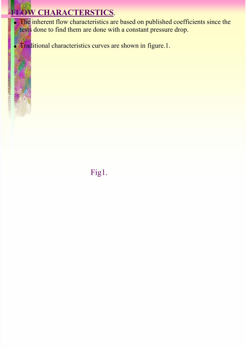
The inherent flow characteristics are based on published coefficients since the
tests done to find them are done with a constant pressure drop.
Traditional characteristics curves are shown in figure.1.
FLOW CHARACTERSTICS.
Fig1.

8/11/2019 Control Valve & Actuator Sizing27012004173744
http://slidepdf.com/reader/full/control-valve-actuator-sizing27012004173744 5/23

8/11/2019 Control Valve & Actuator Sizing27012004173744
http://slidepdf.com/reader/full/control-valve-actuator-sizing27012004173744 6/23
Its usually necessary to pick the next larger valve, and we get more capacity
built-in.
Whenever possible, take a good, hard look at what service conditions are
really possible and try to keep the valve operating out at 75 to 80 percent o
its travel under normal maximum flow conditions.
Check minimum flow required, and make sure that valve will not operate for
any extended periods at less than 5 percent of travel.
Operation in this range can result in damage to the seat due to high velocity
flow.
A valve with high rangeability can meet the requirement for high capacity
and still be able to throttle down to relatively low flows without going under
5 percent of travel.
SIZE CONSIDERATIONS:
8/11/2019 Control Valve & Actuator Sizing27012004173744
http://slidepdf.com/reader/full/control-valve-actuator-sizing27012004173744 7/23
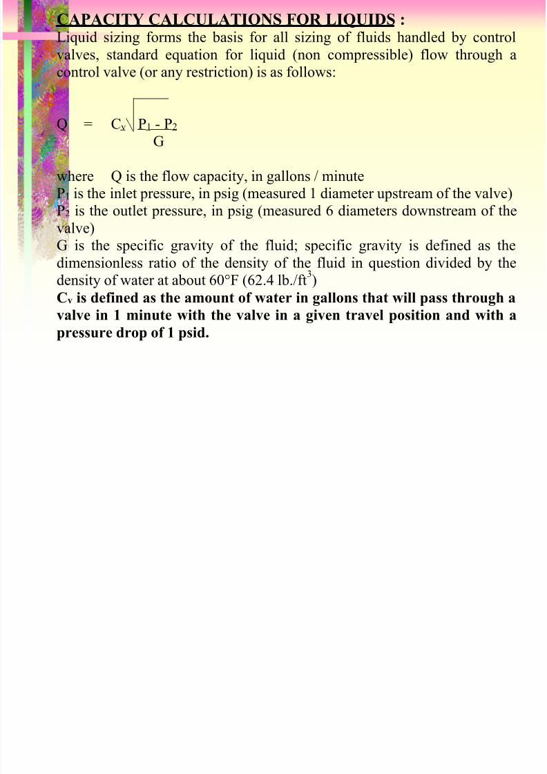
CAPACITY CALCULATIONS FOR LIQUIDS : Liquid sizing forms the basis for all sizing of fluids handled by control
valves, standard equation for liquid (non compressible) flow through a
control valve (or any restriction) is as follows:
Q = Cv P 1 - P 2
G
where Q is the flow capacity, in gallons / minute
P1 is the inlet pressure, in psig (measured 1 diameter upstream of the valve)P2 is the outlet pressure, in psig (measured 6 diameters downstream of the
valve)G is the specific gravity of the fluid; specific gravity is defined as the
dimensionless ratio of the density of the fluid in question divided by the
density of water at about 60°F (62.4 lb./ft
3
)Cv is defined as the amount of water in gallons that will pass through a
valve in 1 minute with the valve in a given travel position and with a
pressure drop of 1 psid.

8/11/2019 Control Valve & Actuator Sizing27012004173744
http://slidepdf.com/reader/full/control-valve-actuator-sizing27012004173744 8/23
In reviewing said equation,
It is apparent that the flow through a valve varies directly with the Cv
and the square root of the specific gravity of the fluid.
Once a set of Cv’s is established for a valve at its various travels, the
flow through the valve for any travel and any service condition canthen be predicted if we know the service pressure drop and the specific
gravity of the fluid.
if the service conditions, the fluid, and the required flow are known for
a given application, we can select the valve to meet the requirements based on the published Cv.

8/11/2019 Control Valve & Actuator Sizing27012004173744
http://slidepdf.com/reader/full/control-valve-actuator-sizing27012004173744 9/23
. Limitations in applying this basic equation to all liquid flowing
conditions
liquids can change phase as they pass through a valve.
Liquid accelerates as it passes through the reduced cross sectional flow
area of a valve, the pressure of the liquid has to drop due to the physics o
the situation.
As the pressure drops, there is a tendency for the liquid to change to thevapour phase.
This change in phase creates bubbles in the flow stream that can take up
more space than the equivalent liquid.
Because they take up more space, the ability of the valve to pass fluid
flow is reduced compared to no bubble condition.
In other words, the capacity of the valve no longer is maintained.
All is not lost, however. Once again, tests can be run to determine when
and if these bubbles will form, depending on valve travel, geometry and
service conditions, and then correction can be made to the equation to
ermit its continued use.

8/11/2019 Control Valve & Actuator Sizing27012004173744
http://slidepdf.com/reader/full/control-valve-actuator-sizing27012004173744 10/23
Fluids flow through a valve is response to a pressure drop, P1 - P2.
The critical factor in determining the degree to which the flow chokes in a
valve is how close the average pressure comes to the vapour pressure as the
fluid passes through the valve.
The degree to which the outlet pressure approaches the inlet pressure is
called the recovery coefficient and is a measure of the efficiency of the flow
path in a given valve.
Rotary valves with their line of sight flow paths are high recovery valves
when compared to globe style valves where the flow path is relatively
tortuous.
FLUID FLOW Vs PRESSURE DROP IN CONTROL VALVE

8/11/2019 Control Valve & Actuator Sizing27012004173744
http://slidepdf.com/reader/full/control-valve-actuator-sizing27012004173744 11/23
A high recovery valve will have a high outlet pressure for a given inlet pressure.
A low recovery valve will have a low outlet pressure.
High recovery valve will be more prone to bubble formation and choking because its minimum pressure will be closer to the vapour pressure for
the fluid
We can characterise the choking potential for a valve by looking at itsrecovery characteristics.
FLASHING & CAVITATION.
Bubble formation, as just covered, is called flashing and can damage trimand can cause problems with capacity. When the bubbles form and thencollapse due to pressure recovery, this is called cavitation and is very hardon trim
VALVE RECOVERY CHARACTERSTICS

8/11/2019 Control Valve & Actuator Sizing27012004173744
http://slidepdf.com/reader/full/control-valve-actuator-sizing27012004173744 12/23
8/11/2019 Control Valve & Actuator Sizing27012004173744
http://slidepdf.com/reader/full/control-valve-actuator-sizing27012004173744 13/23
Like liquids, gases can also choke under certain circumstances but for a
different reason.
As the pressure drop is increased across a valve, the fluid accelerates,
reaching a maximum velocity where the flow cross section is the smallest
(the vena contracta).
The gas can travel no faster than the sonic velocity, and if this velocity isapproached as the pressure drop increases, the capacity increase versus
pressure drop will drop off. This is called critical flow, and the effect is
much like choked flow.

8/11/2019 Control Valve & Actuator Sizing27012004173744
http://slidepdf.com/reader/full/control-valve-actuator-sizing27012004173744 14/23
SIZING FOR TWO PHASE FLOW :
If the fluid being handled is a mixture of the two phases before it enters the
valve, the required flow coefficient Cvr is a combination of the required Cv for
the liquid flow and the required Cg for the gas flow.The equation is,
Cvr = Cv + C g (1 + Fm )
C1
where Fm is the correction factor based on the gas volume ratio Vr .
Vr = Qg 284 Q1 P 1 T1 + Qg
where Qg = gas flow, in scfhQ1 = liquid flow, in gpm
P1 = the inlet pressure, in psia
T1 = the inlet temperature, in degrees Rankine

8/11/2019 Control Valve & Actuator Sizing27012004173744
http://slidepdf.com/reader/full/control-valve-actuator-sizing27012004173744 15/23
PIPING EFFECTS ON CONTROL VALVE OPERATION:
The piping arrangements for a control valve will nearly always be differentfrom the perfectly straight sections used in the standard sizing test, so you
would expect that the installed flow characteristic might differ from the ideal.
The most frequent piping effects to be considered are those that result fromusing reducers on the ends of the valve.
The easy way to address the change in flow capacity due to pipe reducers is
to apply a piping geometry correction factor FP.
The calculated flow can then be multiplied by FP to arrive at the actual flow
with reducers in place.
These factors obviously have a greater effect when dealing with high
capacity valves such as balls and butterflies.

8/11/2019 Control Valve & Actuator Sizing27012004173744
http://slidepdf.com/reader/full/control-valve-actuator-sizing27012004173744 16/23
8/11/2019 Control Valve & Actuator Sizing27012004173744
http://slidepdf.com/reader/full/control-valve-actuator-sizing27012004173744 17/23
SPRING AND DIAPHRAGM SIZING:
valve plug moves down into the body to shut the valve and that the force
required closing the valve is supplied by air pressure loading the top of the
diaphragm.
In same way, you can also have an actuator where the air pressure enters
under the diaphragm and forces it up to open the valve.
If we examine the valve, we can identify the moving parts within theassembly along with the forces that act on these moving parts like diaphragm
plate, the actuator stem, the stem connector, the valve stem, and the plug etc.
In its simplest form, actuator sizing is nothing more than determining the
values for each one of these forces, depending on valve construction and
service conditions.

8/11/2019 Control Valve & Actuator Sizing27012004173744
http://slidepdf.com/reader/full/control-valve-actuator-sizing27012004173744 18/23
8/11/2019 Control Valve & Actuator Sizing27012004173744
http://slidepdf.com/reader/full/control-valve-actuator-sizing27012004173744 19/23
8/11/2019 Control Valve & Actuator Sizing27012004173744
http://slidepdf.com/reader/full/control-valve-actuator-sizing27012004173744 20/23
6) Flange face finish shall be 125-250 AARH
7) Block and bypass control station shall normally be provided for control
valve body sizes upto and including 2 inch body size.
8) Control valve sizes 3 inch and above, hand wheels shall normally be
provided unless indicated otherwise by process licenser.
9) Hand-wheels shall not be provided for valve specified as being for
emergency or shutdown service, nor shall block and bypass control stations
be provided.
10) Pneumatic piping shall be 6 mm OD copper tubing HDPE covered.
Covering shall be heat resistant to direct strong sunlight.
11) Pneumatic connections shall be ¼ “ NPT female minimum.

8/11/2019 Control Valve & Actuator Sizing27012004173744
http://slidepdf.com/reader/full/control-valve-actuator-sizing27012004173744 21/23
12) Brass compression fittings where used shall be protective coated after fitting.
13) All accessories containing electrical circuits shall be certified suitable for use in areas classified as mentioned in engineering data sheet.
14) The permitted maximum noise level measured at one meter from thecontrol valve body shall be 85 dBa.
15) Valve design, body pressure, temperature rating and minimum wallthickness shall comply with ANSI B16.34.
16) Flanges 24” and small shall comply with ASME B16.5. Flanges 30” and
larger shall comply with ASME B16.47. The gasket contact surface oraised flanges shall be smooth finished in the range of 3.2 to 6.3 Ra inaccordance with ASME B46.1.

8/11/2019 Control Valve & Actuator Sizing27012004173744
http://slidepdf.com/reader/full/control-valve-actuator-sizing27012004173744 22/23
17) Irregular body size (e.g. 1.25”, 2.5” and 5”) shall not be used.
18) All valve actuators, regardless of type, shall be sized to provide sufficient
power to stroke the valve through its full travel at 1.25 times the maximum
pressure drop conditions specified for the particular valve.
19) High capacity type filter regulators with set screw adjustment and 50
micrometer filter element shall be supplied for each pneumatic actuator.
20) Electro-pneumatic valve positioner shall be provided for the following duties:
High differential pressure
On all valve having unbalanced plugs
Valves with a trim size 4 inches and larger
All temperature applications
21) All electro-pneumatic positioners must have bypasses to allow local manual
control of the valves. If necessary, boosters shall be supplied to enable this to
be accomplished.

8/11/2019 Control Valve & Actuator Sizing27012004173744
http://slidepdf.com/reader/full/control-valve-actuator-sizing27012004173744 23/23