Embed Size (px)
Citation preview

TECHNICAL REPORT
Control Technology Assessment: Metal Plating and Cleaning Operations
u.s. DEPARTMENT OF HeAL HI AND HUMAN SERVICES Public Health Service
centers for Disease Control National Institute for Occupational Safety and Health


NIOSH TECHNICAL REPORT
CONTROL TECHNOLOGY ASSESSMENT: METAL PLATING AND CLEANING OPERATIONS
John W. Sheehy Vincent D. Mortimer
James H. Jones Stephanie E. Spottswood
U. S. DEPARTMENT OF HEALTH AND HUMAN SERVICES Public Health Service
Centers for Disease Control National Institute for Occupational Safety and Health
Division of Physical Sciences and Engineering Cincinnati, Ohio 45226
December 1984
For aale by the Superi.ntendent of Documents. U.S. Government Printing Offlet', Washington, D.C. 20402
-/- ()."

DISCLAIMER
Mention of company names or products does not constitute endorsement by the National Institute for Occupational Safety and Health (NIOSH).
DHHS (NIOSH) Publication No. 85-102
ii

ABSTRACT
A control technology assessment of electroplating and cleaning operations was conducted by the National Institute for Occupational Safety and Health (NIOSH). Walk-through surveys were conducted at about 30 electroplating plants and 9 in-depth studies at 8 plants. Air sampling and ventilation data and other control information were collected for 64 plating and cleaning tanks. Thirty-one of these were hard chrome plating tanks but cadmium, copper, nickel, silver, and zinc plating tanks were also evaluated. Acid, caustic and solvent cleaning tanks were also evaluated. Worker exposures were found to be controlled below existing and recommended standards.
i11
I.
II.
III.
IV.
V.
VI.
VII.
VIII.
ABSTRACT •
ACKNOWLEDGEMENTS
INTRODUCTION •
METAL PLATING INDUSTRY Mechanical Processes Bath Composition •
Cleaning Tanks Electroplating Baths
HEALTH HAZARD ANALYSIS
CONTENTS
Overview of Chromium Health Effects Acids, Alkalies, and Solvents Metals and Salts
LITERATURE REVIEW OF PLATING PROCESS CONTROLS
STUDY METHODS Ai r Sampling Airflow Measurements
RESULTS Engineering Controls
Hard Chromium Plating Reverse Chromium Stripping • Silver Plating Copper Plating Nickel Plating Cadmium Plating Zinc Plating Acid Cleaning Caustic Cleaning Solvent Degreasing
Work Practices Personal Protective Equipment Hygiene Procedures Monitoring
CONCLUSIONS AND RECOMMENDATIONS
REFERENCES
APPENDIX A. Sampling Results
iv
iii
ix
1
3 3 4 4 6
11 11 16 18
20
26 26 30
32 32 32 58 58 62 65 67 70 73 80 82 84 87 88 88
90
92
97
LIST OF TABLES
Table
1-1 Types of plating or cleaning baths encountered in study • •
2-1 Summary of contaminants which may be released from typical
2-2
2-3
3-1
5-1
6-1
6-2
pre-treatment processes
Summary of contaminants which may be released from typical plating processes
Cathode operating conditions
Hazardous substances from electroplating processes
Sampling and analytical methods • • • • •
Range of values for selected plating tank parameters
Relationship of plating load and tank emissions for one tank
6-3 Airflow measurements for hard chromium tanks with push-pull ventilation • • • • • . • • •
6-4 Average concentrations around tanks with push-pull ventilation
6-5 Selected plant data and average tank-area concentrations for hexavalent chromium compared to average general air concentrations
6-6 Silver tank parameters
6-7 Air sampling results - silver plating
6-8 Copper plating tank parameters
6-9 Air sampling results - copper plating •
6-10 Nickel plating parameters • •
6-11 Air sampling results - nickel plating • . . . . . . 6-12 Cadmium plating parameters
6-13 Air sampling results - cadmium plating
6-14 Air sampling results - zinc plating
6-15 Acid cleaning tank parameters • •
6-16 Air sampling results - acid tanks
v
. . .
2
5
7
8
16
27
33
38
51
55
56
59
60
62
63
66
67
68
69
73
74
77

Table
6-17
6-18
6-19
6-20
A-I
A-2
A-3
LIST OF TABLES (cont'd)
Personal air sampling results - acid tanks
Caustic cleaning tank parameters
Air sampling results - caustic tanks
Air sampling results - tetrachloroethylene degreaser tank
Personal sample statistics
Tank-area sample statistics •
General-area sample statistics
vi
Page
78
80
82
83
98
• 101
106
Figure
6-1
6-2
6-3
6-4
6-5
6-6
6-7
6-8
6-9
6-10
6-11
6-12
6-13
6-14
6-15
LIST OF FIGURES
Hardchrome plating tank with two-sided ventilation
Hardchrome plating tank with two-sided ventilation
Hardchrome plating tank with two-sided ventilation
Hardchrome tank with two-sided ventilation
Tank - three-sided ventilation . . . . . . Average hexavalent chromium concentrations with respect to exhaust rate for all chromium tanks compared to pertinent ceiling limits •.•...••••••••••••••
.
Average hexavalent chromium concentrations with respect to exhaust rate for uncovered tanks with ventilation on two sides
Average total chromium concentrations with respect to exhaust rate for uncovered tanks with ventilation on two sides
Average hexavalent chromium concentrations with respect to exhaust rate divided by the ventilation control distance for uncovered tanks with ventilation on two sides • • • • •
Average hexavalent chromiun concentrations with respect to exhaust rate for uncovered tanks with ventilation on one or three sides compared to representative curves for two-sided ventilation • . • • • • • • • • • • . • • • • •
.
Average hexavalent chromium concentrations with respect to exhaust rate divided by the ventilation control distance for uncovered tanks with ventilation on one or three sides compared to representative curves for two-sided ventilation
Effect of full and partial covers on controlled airflow for a tank with two-sided ventilation • • • • • • • • • • •
Average hexavalent chromium concentrations with respect to exhaust for covered tanks compared to representative curves for uncovered two-sided ventilation • • • • • • • • • •
Average hexavalent chromium concentrations with respect to exhaust rate provided by ventilation control distance for covered tanks with ventilation on one or three sides compared to representative curves for uncovered two-sided ventilation
Average hexavalent chromium concentrations with respect to exhaust rate for one tank with and without a cover compared to pertinent ceiling limits •••••••••••••
vii
Page
34
34
35
36
37
38
40
41
43
44
45
47
48
49
50

Figure
6-16
6-17
6-18
6-19
6-20
6-21
6-22
6-23
6-24
6-25
6-26
6-27
6-28
6-29
LIST OF FIGURES
Hard chrome plating tanks with push-pull ventilation
Tanks A and B with covers and push-pull ventilation •
Schematic of tank with push-pull ventilation
Average hexavalent chromium exhaust rate for tanks with to pertinent ceiling limits
concentrations with respect to push-pull ventilation compared . . .
Silver plating tank 1D
Copper plating tank, IF
Cadmium plating tank - ventilated
Zinc automatic rack plating line
Zinc plating tank • . . . . . . . Acid cleaning line and exhaust hood • •
Side view of acid hood and tank
Tank 7H - acid etch • . . . . Caustic cleaning tank with cover . . . Solvent degreaser with cover open
viii
52
53
53
54
61
64
68
71
72
75
75
76
81
83

ACKNOWLEDGEMENTS
The authors would like to acknowledge the assistance of Alfred A. Amendola, Mary Ellen Cassinelli, Alex Cohen, Peter M. Eller, John C. Frede, Frank W. Godbey, Robert T. Hughes, Donald E. Hurley, Daniel R. Kemme, Sharon L. Kercher, Kenneth F. Martinez, Dennis M. O'Brien, Vernon Putz-Andersen, David E. Schroer, Kenneth M. Wallingford, and Ruby Watson of NIOSH during the field surveys conducted for this study. Mary Ellen Cassinelli of NIOSH or the Utah Biomedical Test Laboratory performed all air sample analysis required for the study. Stanley A. Shulman provided invalu,able _ assistance with statistical analysis of data collected during the study. Rosalynd J. Kendall was extremely helpful in providing editorial comments on the manuscript. We also wish to recognize the interest and assistance of Mr. King Ruhly, Executive Director, Metal Finishing Suppliers Association.
ix

I. INTRODUCTION
As a result of the Occupational Safety and Health Act of 1970 (PL 91-596), the National Institute for Occupational Safety and Health (NIOSH) has instituted a major program to prevent occupational health problems through the application of control technology in the workplace. The goal of this program is to stimulate private industry to prevent hazardous exposures to workers and to document successful approaches and applications of control measures. The plating and cleaning (metal finishing) industry was selected for a control technology assessment study because of the use of substances that are recognized health hazards such as hexavalent chromium, sulfuric acid, and cyanide. A large number of plating and cleaning shops involve manual operations such as dipping and masking where potential exposure to hazardous substances is high. In addition, a major portion of the plating and cleaning industry are small businesses, lacking the resources to develop information on the prevention of excessive occupational exposure on their own.
The study was performed through a review of the technical literature on plating processes and equipment and their associated hazards; preliminary surveys of approximately 30 electroplating plants, and 9 in-depth surveys at B electroplating plants. Preliminary surveys were conducted to further identify control methods, select plant locations for in-depth surveys, and to finalize sampling protocol. The in-depth surveys consisted of industrial hygiene measurements of selected hazards, engineering evaluation, and documentation of control methods. The in-depth survey sites, their plating and cleaning baths, and the associated hazards are presented in Table 1-1.
This report examines control methods and systems for specific plating baths and cleaning solutions such as chromic acid, cadmium, cyanide and mixed acid cleaners. Sixty-four plating and cleaning tanks were evaluated with the major emphasis on hard chromium plating. Individual plant reports which include more detailed information on specific plant processes and controls are available from the National Technical Information Service*.
* National Technical Information Service, Port Royal Road, Springfield, Virginia 22161.
1

Plant No.
1
2
3
4
5
6
7
8
9
Table 1-1. Types of Plating or Cleaning Baths Encountered in Study
Type of Plating or
Plant Description Cleaning Bath
Plate electrical Silver (cyanide) components Copper strike
(captive production shop) Zinc (low cyanide) Nickel (h'at t s) Chromic acid De-smut Soak clean Acid clean Acid clean Bright dip
Hardchrome job-shop Chromic acid
Hardchrome job-shop Chromic acid
Hardchrome job-shop Chromic acid
Hardchrome job-shop Chromic acid
Hardchrome production- Chromic acid shop Acid clean
Acid clean
Airline maintenance Chromic acid (captive shop) Cadmium cyanide
Nickel (sulfamate) Copper strike Silver cyanide Acid etch Degreaser
Hardchrome job-shop Chromic acid
Airline maintenance Chromic acid (captive shop) Cadmium cyanide
Nickel plate Nickel electroless
2
Hazardous Substance
Ag, CN Cu, CN ZnO, CN Ni Cr+6 , H2SO4 NaOH, KCN NaOH HCI HN03, H2SO4 HN03
Cr+6 , H2SO4
Cr+6 , H2SO4
Cr+6 , H2SO4
Cr+6 , H2 SO4
Cr+6 , H2SO4 HF, HN03, H2 SO4 HN03
Cr+6 , H2 SO4 Cd, CN Ni Cu, CN Ag, CN H2SO4 C2Cl4
Cr+6 , H2 SO4
Cr+6 , H2SO4 Cd, CN Ni Ni

II. METAL PLATING INDUSTRY
Metal parts are plated for several reasons, ie., to impart hardness, wear resistance and corrosion resistance; to improve appearance; and to restore worn parts. The parts plated may be made from a number of materials including iron and steel, stainless steel, zinc castings, aluminum, nickel, lead-tin-antimony, lead and lead alloys, and leaded brass. Plastic is also plated but this type of plating was not included in the study.
In electroplating and anodizing, metal is deposited on the basis material as a result of electrochemical processes. This definition includes the processes generally referred to as electroplating and anodizing. Electroless plating is a chemical (Le., catalytic) process; an electron current is involved. The plating process also includes the related pre-treatment and post-treatment processes that are necessary to obtain a plated surface of the desired quality.
The Environmental Protection Agency has estimated l that approximately 160,000 production workers are engaged in plating operations in the United States. Included are 40,000 platers in 2,900 job shops in Standard Industrial Classification (SIC) Nos. 3471 and 3479, and 120,000 production platers in 6,000 captive shops. (Not included in these numbers are platers in printed circuit board manufacturing.)
MECHANICAL PROCESSES
Mechanical plating operations include barrel, manual or vat, and automatic processing. Barrel processing is applied to small component parts which would be difficult or uneconomical to plate conventionally. There are two general types of barrel processing. The first uses an open-ended barrel unit which contains the component parts and plating solution; the parts and solution are rotated together at an angle to complete the plating process. The second, more modern type of barrel plating uses a totally enclosed, submersible barrel driven by a belt drive or gear system from above the plating solution. Both of these barrel systems allow for free movement of the component parts when the barrel is rotated. 2 In the case of electroless plating the barrels can be constructed from "Lucite", or polypropylene because no electrical connections are required. 3
The manual or vat process incorporates a series of tanks that contain the appropriate cleaning and plating solutions. Parts are racked or placed on hangers and manually transferred from tank to tank. The racks are made of a highly conductive material and are used as current carrying devices which complete the electrical circuitry. Vat or manual plating is labor-intensive and brings the worker into close proximity to the tank solutions.
In automatic processing, parts are manually racked or hung on devices similiar to those used in manual processing, or placed in barrels as described in barrel processing, and automatically transferred from tank to tank in a predetermined sequence. 2 Parts are transferred by conveyor, thereby separating the worker from close proximity to the tank solutions.
3

Along with loading barrels and racking parts, the platers may file, hand clean, and mask parts to be plated, transfer chemicals to tanks, or empty tanks. In most manual operations, the platers major task is loading/unloading parts from tanks by hand or with an overhead hoist.
BATH COMPOSITION
Cleaning Tanks
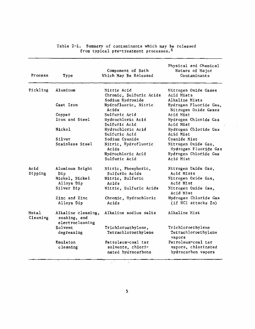
Cleaning or pretreatment solutions condition the metallic surface that is to be plated by ~emoving substances such as polishing compounds, protective greases, fingermarks, and scale or corrosion. The preplating condition of a part greatly affects the performance of deposits on its surface. Pretreatment operations involve one or more of the following processes: 1) acid cleaning or pickling; 2) alkaline cleaning including soaking, spraying, and electrolytic cleaning; 3) emulsion cleaning; 4) salt bath descaling; 5) solvent cleaning or vapor degreasing; and 6) ultrasonic cleaning. A summary of contaminants which may be released from pretreatment processes is presented in Table 2-1. 2 ,4,5
Acid cleaning removes oxide film from the surface of component parts; removal of thick oxide layers and some metal is called pickling and removal of thin oxide layers is called bright dipping.
Alkaline cleaning removes oil and solid soils from the workpiece surface primarily by the detergent nature of the solution. Alkaline cleaners are classified as soak, spray, or electrolytic. A soak cleaner is primarily used for easily removable soil and on parts wit" difficult to reach surfaces. Spray cleaners are used when a combination of detergent and mechanical action on a workpiece is needed. The best of the three alkaline cleaners is the electrolytic type, Soil is removed by the agitation of the gas bubbles which evolve during electrolysis, and, in addition, soil particles may become electrically charged and be repelled from the workpiece surface.
Another method for surface preparation of workpieces is emulsion cleaning. Emulsions are made up of common organic solvents. Salt bath descaling employs molten salts at 400' to 540'C to clean stubborn oxides from corrosionresistant alloys. Solvent cleaning, referred to as vapor degreasing, is used primarily to remove lubricants high in nonsaponifiable oils, sulfurized or chlorinated compounds, and soluble soils. Common solvents used in this process are trichloroethylene and tetrachloroethylene. Ultrasonic cleaning is a method of pretreatment which uses weak alkaline solutions in combination with a cavitation principle. Minute vacuum bubbles are produced which bombard the surface of the workpiece thereby dislodging soil or dirt particles.
A typical metal-on-metal electroplating pretreatment sequence may include: solvent degreasing and an alkaline· soak to remove grease and oil, an acid cleaning to remove scale and oxide, electrolytic alkaline cleaning to remove soil particles, and an acid dip to remove light oxide films and activate the workpiece surface. A water rinse is performed between each operation.
4
Process
Pickling
Acid Dipping
Metal Cleaning
Table 2-1. Summary of contaminants which may be released from typical pre-treatment processes. 6
Type
Aluminum
Cast Iron
Copper Iron and Steel
Nickel
Silver Stainless Steel
Aluminum Bright Dip
Nickel, Nickel Alloys Dip
Silver Dip
Zinc and Zinc Alloys Dip
Alkaline cleaning, soaking, and electrocleaning
Solvent degreasing
Emulsion cleaning
Component of Bath Which May Be Released
Nitric Acid Chromic, Sulfuric Acids Sodium Hydroxide Hydrofluoric, Nitric
Acids Sulfuric Acid Hydrochloric Acid Sulfuric Acid Hydrochloric Acid Sulfuric Acid Sodium Cyanide Nitric, Hydrofluoric Acids
Hydrochloric Acid Sulfuric Acid
Nitric, Phosphoric, Sulfuric Acids
Nitric, Sulfuric Acids
Nitric, Sulfuric Acids
Chromic, Hydrochloric Acids
Alkaline sodium salts
Trichloroethylene, Tetrachloroethylene
Petroleum-coal tar solvents, chlorinated hydrocarbons
5
Physical and Chemical Nature of Major
Contaminants
Nitrogen Oxide Gases Acid Mists Alkaline Mists Hydrogen Fluoride Gas, Nitrogen Oxide Gases
Acid Mist Hydrogen Chloride Gas Acid Mist Hydrogen Chloride Gas Acid Mist Cyanide Mist Nitrogen Oxide Gas,
Hydrogen Fluoride Gas Hydrogen Chloride Gas Acid Mist
Nitrogen Oxide Gas, Acid Mists
Nitrogen Oxide Gas, Acid Mist
Nitrogen Oxide Gas, Acid Mist
Hydrogen Chloride Gas (if HCl attacks Zn)
Alkaline Mist
Trichloroethylene Tetrachloroethylene vapors
Petroleum-coal tar vapors, chlorinated hydrocarbon vapors
Electroplating Baths
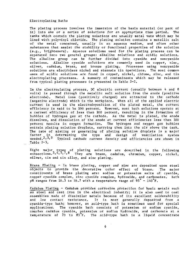
The plating process involves the immersion of the basis material (or part of it) into one or a series of solutions for an appropriate time period. The tanks which contain the plating solutions are usually metal vats which may be lined with polyvinyl chloride. The plating solution contains a metallic salt of the metal concerned, usually in an aqueous medium, and often other substances that assist the stability or functional properties of the solution (e.g., brighteners). Aqueous solutions used for the plating process can be separated into two general groups: alkaline solutions and acidic solutions. The alkaline group can be further divided into cyanide and noncyanide solutions. Alkaline cyanide solutions are commonly used in copper, zinc, silver, cadmium, brass, and bronze plating. Processes using noncyanide solutions are electroless nickel and stannate tin operations. The most common uses of acidic solutions are found in copper, nickel, chrome, zinc, and tin electroplating processes. A summary of contaminants which may be released from typical plating processes is presented in Table 2-2.
In the electroplating process, DC electric current (usually between 4 and 8 volts) is passed through the metallic salt solution from the anode (positive electrode). Metal ions (positively charged) are attracted to the cathode (negative electrode) which is the workpiece. When all of the applied electric current is used in the electrodeposition of the plated metal, the current efficiency is said to be 100 percent. However, most bath solutions operate at a current efficiency of less than 100 percent, resulting in the formation of bubbles of hydrogen gas at the cathode. As the metal is plated, the anode dissolves, and dissolution of the anode at current efficiencies less than 100 percent results in oxygen formation. The hydrogen and oxygen gas bubbles entrain plating solution droplets, carrying them into the air above the tank. The rate of misting or generating of plating solution droplets is a major factor in determining the type and design of ventilation system needed. 2 ,3,9 Typical cathode current density and efficiencies are shown in Table 2-3.
Eight major types of plating solutions are described in the following subsections. 3 ,4,5,7,8 They are brass, cadmium, chromium, copper, nickel, silver, tin and tin alloy, and zinc plating.
Brass Plating - In brass plating, copper and zinc are deposited upon steel objects to provide the decorative color effect of brass. The major constituents of brass plating are: sodium or potassium salts of cyanide, copper cyanide complex, zinc cyanide complex, hydroxide, and carbonates. Bath
3 7 0 0
pH ranges from 10. to 10. with a temperature range of 95 - 140 F.
Cadmium Plating - Cadmium provides corrosion protection for basic metals such as steel and cast iron in the electrical industry; it is also used to coat assemblies made of dissimilar metals because of its excellent solderability and low contact resistance. It is most generally deposited from a cyanide-type bath: however, an acid-type bath is sometimes used for special applications. The cyanide bath consists of potassium or sodium cyanide, complex cadmium cyanide, ~otassium or sodium hydroxide, and carbonate at a temperature of 70 to 85 F. The acid-type bath is a liquid concentrate
6

containing cadmium fluoboric acid, boric acid, and ammonium fluoborate. The pH of the acid-tlpe bath is normally between 3.0 to 3.5, and the temperature approximately 75 F.
Table 2-2. Summary of contaminants which mal be released from typical plating processes.
Type
Acid
Process
Chromium Copper(over 90°F)
Iron
Nickel (insoluble anodes, sulfate bath) Nickel (airagitated sulfamate bath) Tin Zinc
Alkaline Nickel (electroless) Tin
Cyanide Brass, Bronze, Copper-Cadmium Bright Zinc Sodium hydroxide Copper (except conventional bath) Strike Solutions
Tin-Zinc Alloy
Zinc (using insoluble anodes)
Fluobo- Lead rate
Component of Bath Which May
Be Released
Chromic acid Copper sulfate, Sulfuric acid
Chloride salts, Hydrochloric acid
Nickel sulfate
Nickel sulfamate
Tin halide Zinc chloride
Ammonium hydroxide Sodium stannate
Cyanide salts, Ammonium hydroxide Cyanide salts Alkaline mist Cyanide salts Sodium hydroxide Cyanide salts Cyanide salts Cyanide salts, Potassium hydroxide
Cyanide salts Sodium hydroxide
Lead fluoborate Fluoboric acid
Physical and Chemical Nature of Contaminant
Chromic acid mist Sulfuric acid mist
Hydrochloric acid mist
Nickel sulfate mist
Sulfamate mist
Halide mist Zinc chloride mist
Ammonia gas Tin salt mist
Cyanide mist* Ammonia gas Cyanide*
Cyanide* Alkaline mist Cyanide mist* Cyanide mist* Cyanide,* Alkaline mist
Cyanide mist* Alkaline mist
Fluoborate mist Hydrogen fluoride gas
(*) NOTE: HCN gas may be evolved due to the acidic action of C02 in the air.
7
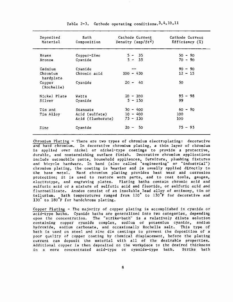
Table 2-3. Cathode operating conditions. 3 ,4,10,11
Deposited Bath Cathode Current Cathode Current Material Composition Density (amp/ft 2) Efficiency (%)
Brass Copper-Zinc 5 - 35 50 - 90 Bronze Cyanide 5 - 35 70 - 90
Cadmium Cyanide 90 - 90 Chromium Chromic acid 100 - 430 12 - 15 hardplate
Copper Cyanide 20 - 40 50 (Rochelle)
Nickel Plate Watts 10 - 100 95 - 98 Silver Cyanide 5 - 150 99
Tin and Stannate 30 - 400 60 - 90 Tin Alloy Acid (sulfate) 10 - 400 100
Acid (fluoborate) 75 - 130 100
Zinc Cyanide 20 - 50 75 - 95
Chromium Plating - There are two types of chromium electroplating: decorative and hard chromium. In decorative chromium plating, a thin layer of chromium is applied over nickel or nickel-type coatings to provide a protective, durable, and nontarnishing surface finish. Decorative chromium applications include automobile parts, household appliances, furniture, plumbing fixtures and bicycle hardware. In hard (also called "engineering" or "industrial") chromium plating, the coating is heavier and is usually applied directly to the base metal. Hard chromium plating provides heat wear and corrosion protection; it is used to restore worn parts, and to coat tools, gauges, electrotype, and engraving plates. Plating baths contain chromic acid and sulfuric acid or a mixture of sulfuric acid and fluoride, or sulfuric acid and fluorosilicate. Anodes consist of an insoluble lead alloy of antimony, tin or tellurium. Bath temperatures ranged from 110° to 130°F for decorative and 130° to 180°F for hardchrome plating.
Copper Plating - The majority of copper plating is accomplished in cyanide or acid-type baths. Cyanide baths are generalized into two categories, depending upon the concentration. The "strike-bath" is a relatively dilute solution containing copper cyanide complex, sodium or potassium cyanide, sodium hydroxide, sodium carbonate, and occasionally Rochelle salt. This type of bath is used on steel and zinc die castings to prevent the deposition of a poor quality of copper coating by chemical displacement, before the plating current can deposit the material with all of the desirable properties. Additional copper is then deposited on the workpiece to the desired thickness in a more concentrated acid-type or cyanide-type bath. Strike bath
8
temperatures are at 70° to 80°F, and the pH is 12 to 12.6; the regular cyanide-type bath operates at a temperature of 130° to 160°F, and a pH of 13.
There are two types of acid baths (sulfate and fluoborate) used in copper plating. Sulfate baths are operated at bath temperatures of 85° to 110°F and a pH of less than 1. 7. Acid sulfate solutions contain copper sulfate and sulfuric acid. The fluoborate baths operated at temperatures from 100° to 150°F and contain copper fluoborate, fluoboric acid and boric acid.
Nickel Plating - Nickel electroplating solutions consist of the following types: "Wat ts," sulfama te, f luoborate, and "all-chloride." All baths contain boric acid and usually nickel chloride. The Watts bath (pH 3.0 to 5.2) contains nickel sulfate, the sulfamate bath (pH 3.0 to 5.0) contains nickel sulfamate, and the fluoborate bath (pH 2.5 to 4.5) contains nickel fluoborate. The all chloride bath (pH 0.9 to 1.1) contains only boric acid and nickel chloride. Proprietary chemicals are added to the Watts bath to brighten the metal surface in decorative applications. This type of plating process is the most widely used. Nickel plating is performed at bath temperatures of 110° to 150°F.
Silver Plating - Silver is electrodeposited only from cyanide-type solutions. The operation is somewhat similiar to copper plating in that the silver is generally applied in three successive layers. This type of process is called strike plating. The first strike bath is generally applied to steel, jewelry, lighting fixtures, and novelty articles. It contains potassium silver cyanide, potassium copper cyanide, potassium cyanide, and potassium carbonate. The silver cyanide concentration in the first strike bath is typically one-tenth that of the final plating bath. The second strike bath applied to steel and tableware, has the same composition as the first strike bath for nonferrous metals. This bath contains potassium silver cyanide, and potassium cyanide at a concentration of approximately one-sixth that of the final bath. The plating final bath (thickest layer) generates the desired thickness and is applied to such items as bearings and electroforms. This bath contains potassium silver cyanide, potassium cyanide, potassium carbonate, and brighteners. Temperatures for all these baths are 70° to 80°F.
Tin and Tin Alloy Plating - Tin and tin alloy is used to plate continuous strip, wire, and cord steel; piston rings and cylinders; refrigerator parts; kitchenware; and electrotypes. A copper undercoat is required where tin is applied to ferrous metals. Tin and tin-alloy plating increases solderability and affords corrosion resistance. Tin also prevents the seizing and scoring of bearing surfaces. Materials are deposited from acid and alkaline solutions. The three types of acid baths are sulfate, halogen, and fluoborate. The sulfate-type bath contains stannous sulfate, sulfuric acid, and cresolsulfonic or phenol sulfonic acid; temperatures of 70 to 85 OF are common. The halogen bath contains stannous chloride, sodium fluoride, potassium bifluoride, and sodium chloride, and the bath operates at pH 2.7 and 150°F. A fluoborate-type bath is used for special applications where high plating rates are desired. It contains stannous f luoborate, and f luoboric acid and the temperature range is 70° to 120°F.
9

The alkaline-type bath contains either sodium or potassium potassium hydroxide, and sodium or potassium carbonate. from 160° to 195°F.
stannate, sodium or Temperatures range
Zinc Plating - Zinc elect roplating protec ts iron and steel against rusting. It is applied to ferrous products such as wire strip, sheet, and conduit. Zinc offers the same corrosion protection as nickel or other coatings, but at a lower cost. Most zinc plating is done in cyanide baths (pH greater than 13.0) which contain sodium cyanide, zinc oxide or cyanide, sodium carbonate, and sodium hydroxide. Zinc is also plated in alkaline solutions containing chelating agents such as zinc pyrophosphate; in chloride baths consisting of zinc chloride and ammonium chloride; and in zinc sulfate solutions which contain zinc sulfate, and salts such as aluminum chloride and sodium sulfate, or ammonium chloride and ammonium sulfate.
Electroless Plating
The electroless plating process involves the use of a catalytic reaction to deposit the metal on a workpiece without the use of electric current. 2 The most extensively used plating metals in electroless plating are copper and nickel; however, cobalt and to a lesser extent iron, arsenic, gold, and palladium are also used. Nickel baths can be either acidic or alkaline. Both contain nickel chloride and sodium hypophosphite and are to be operated at 190°F. The acid baths also contain sodium glycollate and, to maintain the pH between 4 and 6, sodium hydroxide. Alkaline baths, with pH from 8 to 10, also contain ammonium chloride and sodium nitrate; the pH is adjusted with ammonia. Electroless copper baths with a pH of 11.5, consist of copper sulfate, a complexing agent, formalin (40 percent formaldehyde) or paraformaldehyde, and sodium hydroxide.
10

III. HEALTH HAZARD ANALYSIS
OVERVIEW OF CHROMIUM HEALTH EFFECTS
The most widely perceived hazard among platers is exposure to chromium during chrome plating. A number of studies of adverse health effects among chroUle platers have been published. They range from case reports of acute effects to studies of excess mortality due to chronic effects of chromium exposure. Adverse health effects have been reported for chrome plating workers since 1928, only three years after perfection and commercialization of the chrome plating process. In that year Bloomfield and Blum12 reported that 17 of 19 workers in six chrome plating plants had symptoms including perforated septa, ulcerated septa, inflamed mucosa, nosebleed and chrome holes. Exposures to chromium were estimated on the basis of 39 samples; the exposures ranged from 0.06 to 1.8 mg/m3• Six workers had been exposed to 0.06 mg/m3 ; all six had inflamed mucosa and four had nosebleed.
In the same year Blair13 reported 12 cases of chrome ulcers, perforated septa, ulcerated septa, or respiratory tract irritation. No environmental levels of chromium were given, but installation of an "efficient" ventilation system was reported to prevent symptoms. Dixon14 in 1929 reported on 18 cases of perforated septa, all from one chrome plating plant with poor ventilation. He reports that he had not encountered this problem in other chrome plating plants with adequate ventilation; however, no air concentrations were reported. Five other workers, who had been employed at the plant for less than a month showed signs of ulcerated septa.
In 1930, the Medical Inspectorate of Factories, London15 , reported on the examination of 223 chrome platers. The results showed that 95 had dermatitis, ulcers, or scars of old ulcers and 116 had either perforation or ulceration of the septum or devitalization of the mucous membrane. No environmental data is given. Again, the report states that the "risk can only be eliminated by efficient exhaust ventilation."
Zvaifler and Gresh16 ,17, in 1944, reported on approximately 100 cases of exposure to chromic acid in anodizing operations, which uses a 5 percent chromic acid solution, compared to 25 to 50 percent used in chrome plating. All of the cases showed ulceration of the septum with varying degrees of severity. Skin rashes were also reported to be common. Air concentration of chromium at the anodizing tank ranged from 0.21 to 0.62 mg/m3•
Pascale, et al18 reported in 1952 on a case of acute hepatitis with jaundice in a chrome plating worker. In four other workers, hepatic tests and liver biopsy showed mild to moderate abnormalities. These four workers had no symptoms related to the liver but did have the nasal lesions more commonly attributed to chromium exposure. No exposure levels were reported.
In 1955, Lloyd 19 after the exhaust about five days.
reported on nine cases of ulcerated septa ventilation of a plating tank failed and was Again, no exposure data were reported.
11
that occurred inoperable for
Kleinfeld and Ros s 020, in 1965, reported nine cases of nasal damage, ranging from injection of the septum to septal perforation. No local exhaust was used at the plating tanks and air levels of chromium were reported to range from 0.09 to 0.73 mg/m3 •
In 1967, Hanslian et al21 reported on a study of 77 chrome platers from eight plants. Nasal mucosa changes were noted in 95 percent of the workers. In addition, 12 cases of chronic tonSillitis, 5 cases of chronic pharyngitis, and 14 individuals with papillomas of the uvula or the upper arch of the oral cavity were re~orted. The average air level of chromium in the eight plants was 0.414 mg/m. Only two plants had air concentrations which were entirely below 0.1 mg/m J • Average air levels for each plant over the period 1956 to 1967 ranged from 0.023 to 0.681 mg/m3•
A health problem associated with an electrolytic chrome stripping operation was reported by Mitche1122 in 1969. When two workers developed ulcerated septa, the source of high chromium exposures was found to be an unventilated chrome stripping tank, and not the chrome plating tanks present at the plant. Levels of chromium measured in the workers' breathing zone varied from 0.12 to 0.57 mg/m3•
A study of 13 chrome platers and nine nickel and zinc platers was reported by Cavazzani and Viola23 in 1970. They observed nasal mucosa damage of varying severity among the chrome platers. Macroscopically visible lesions included catarrhal, hypertrophic and atrophic rhinitis, and nasal septa ulceration and perforation. In addition, cytological alterations were found to include metaplasia, metachromasia, and signs of cellular suffering. Slight nasal mucosa irritation was the only effect found among the nickel and zinc platers.
Gomes24 , in 1972, reported on a study of 303 electroplaters. Lesions due to chromic acid were found in 86.8 percent of these workers. Eight hard-chrome plating plants were surveyed, two of which had air levels less than 0.05 mg/m3 • The other six plants had air levels of chromium ranging from 0.05 to 0.7 mg/m3• All 35 workers examined from these eight plants had either cutaneous or mucous lesions. Of the 63 decorative, chrome-plating plants surveyed, 33 had air levels of chromium less than 0.05 mg/m3 • Air levels of chromium ranged up to 0.35 mg/m3 for these plants. Eighty-three percent of the 223 decorative chrome platers examined had either cutaneous or mucous lesions. In addition, 93.5 percent of the 45 workers using chrome brighteners had cutaneous or mucous lesions.
In 1973, Markel and Lucas 25reported on a NIOSH survey of a decorative chrome plating plant. None of the 32 workers examined had nasal mucosal inflammation that was attributed to chromium exposure, and no workers had ulcerated or perforated septa. Two active cases of chrome ulcers were found and four reports of past chrome ulcers. Worker exposure to chromium ranged from less than 0.0005 mg/m3 to 0.003 mg/m3•
A second NIOSH investigation reported in 1973 by Kramkowski 26 involved a zinc plating operation. One worker reported occasional nasal irritation when working over the plating tanks to add solutions, but there were no other reports of symptomatic effects by the four workers interviewed. Worker
12

exposure to chromium averaged 0.0024 and ranged from less than 0.0012 to 0.0036 mg/m 3 ; worker exposure to zinc ranged from 0.0015 to 0.0061 mg/m3 • Other exposures, including cyanide, hydrogen chloride and nitric acid, were low.
Another NIOSH investigation, reported by symptoms among 15 workers interviewed that acids or other substances used in a plant brass, copper, tin, cadmium, and silver. No
Kramkowski in 197327 found no , were consistent with exposure to electroplating with zinc, nickel, air levels were reported.
A fourth NIOSH survey, reported in 1973 by Cohen and Kramkowski 28 , evaluated worker health at a nickel-chrome, zinc, and copper-cadmium plating plant. Nasal mucosa changes were found in 95 percent of the 37 nickel-chrome plating workers examined. Only one (7 percent) of the 15 workers from the other plating operations examined had nasal mucosa changes. That worker had a previous history of possible chromate exposure. The greater the length of employment in the nickel-chrome plating operation, the more severe were the nasal mucosa changes. In addition, five workers in nickel-chrome plating had "chrome ulcers" on the hands. Average chromium (VI) air concentrations were 0.0029 mg/m3 in nickel-chrome plating and 0.0003 mg/m3 in the other plating areas. Total chromium air concentrations in the nickel-chrome plating area varied from none detected to 0.0493 mg/m3 with an average of 0.0071 mg/m3 • Nickel concentrations in this area ranged from 0.0089 to 0.0712 mg/m 3 with an average of 0.0271 mg/m3. Air levels of zinc in the zinc plating area ranged from 0.0008 to 0.0042 mg/m 3 with an average of 0.0016 mg/m3 • Other substances monitored included phosphate, cyanide, nitrate, and chloride. Levels found were all well below recommended standards.
Lucas and Kramkowski 29 , in 1975, reported on a NIOSH survey of a hard-chrome plat ing plant. Eleven workers were examined. Nosebleeds were reported by four, nasal septal perforation by four, chrome ulcers by nine, and various types of stomach pain or distress by five. Worker exposure to chromium (VI) ranged from less than 0.001 mg/m3 to 0.020 mg/m3 with an average of 0.004 mg/m3 •
A retrospective mortality study of 1,238 chrome platers and 1,284 control workers was reported by Royle30 in 1975. The plater population consisted of past and current workers (as of May 31, 1974) in 54 plants. A minimum employment of three months in a chrome plating plant were required for inclusion in the cohort. The control population was drawn from other departments of the larger firms and from two unrelated industrial firms in the same geographical area. Controls were matched for sex and age. Prior to May 31, 1974, 112 deaths were found among platers and 104 among controls. A statistically significant excess of deaths from malignant. neoplasm was found among the platers. The excess was due to increases in lung and pleural cancer, gastrointestinal cancer, and cancer of other sites. The author concludes that the findings are suggestive of a general cancer problem among chrome platers.
Royle3l also reported on a morbidity study of 997 platers and 1,117 controls and an industrial hygiene study of 42 of 54 plating plants from which the population for this and the previous study were drawn. The morbidity study
13
was conducted using the British Medical Research Council's Questionnaire on Respiratory Symptoms with additional questions about bronchial asthma, hay fever, and the occurrence of skin and nasal lesions. Respiratory symptoms, with the exception of effort dyspnea, were experienced to a greater extent by the platers. The risk of skin and intranasal ulceration was shown to increase progressively, the longer the period of chromic acid exposure. The reported prevalence of nasal ulcers and perforation of less than 15 percent were considered to be low because of the lack of physical exams. Many platers have nasal ulceration and even septal perforation without being aware of it. Air levels of chromium measured were less than 0.015 mg/m3 at all plants but two. In these two plants, the air levels of chromium exceeded 0.05 mg/m 3•
In 1976, Roper32 reported on a NIOSH survey of a nickel, chromium, cadmium, and tin plating operation. Four of 34 workers interviewed reported a history of dermatitis, which may have been caused by nickel exposure. Nausea was also reported when workers were near a cyanide strip tank. Air measurements were quite low for nitric acid, hydrochloric acid, sodium hydroxide, trichloroethylene, chromium, and nickel. Cyanide levels near the strip tank approached the OSHA standard of 5 mg/m3• Chromium air levels were less than 0.0015 mg/m3 and nickel air levels were 0.002 mg/m3 or less.
A NIOSH investigation at a lead plating operation was reported by Gilles and Philbin33 in 1976. No adverse health effects were found in the one worker. Lead air measurements were all below detection limits which were 0.002 mg/sample. Assuming a three-hour sample (similar to other samples collected in this survey), this would mean a detection limit of about 0.01 mg/m3•
Gunter34 , in 1978, reported on a survey of a silver plating operation. No adverse health effects were noted in the six workers, but a silver air level of 0.04 mg/m3 was measured. Workers were not routinely near the plating tank.
Pryor 35 , in 1978, reported on a NIOSH survey of a decorative chrome-plating operation. No adverse health effects were detected in the one plater. Chromium air levels were below the detection limit of 0.012 mg/m3.
Blair and Mason36 reported in 1980 on a finding of elevated mortality rates for selected cancers among whites in U. S. counties with a high percentage (70.1 percent) of electroplating workers. The mortality rates for several cancers, particularly esophagus and larynx, were statistically higher than rates for a group of control counties with similar demographic characteristics.
Blair37 also reported in 1980 on a study of metal polishers and platers. A cause-specific proportionate mortality study of 1,292 white male metal platers and polishers was conducted. The study group was identified from obituary listings in the Journal of the Metal Polishers, Buffers, Platers, and Allied Workers International Union. Compared to the U. S. white male population, the proportion of deaths due to esophageal and primary liver cancer were statistically increased.
A proportionate mortality study of 977 zinc-chromate spray painters reported by Dalager, et a138 in 1980. A group of 276 chrome platers
14
was was
also studied. Only 48 deaths were seen among the chrome platers with no relative excess of cancer compared to the U. S. white male population.
Silverstein, et a139 reported, in 1981, a proportional mortality study of workers in a die-casting and electroplating plant. The major operations of the plant were zinc alloy die casting and chrome and nickel plating. The study group included 225 deceased workers from this plant. A statistically significant increase in lung cancer deaths was observed.
Ahrenholz and Anderson40 , in 1981, reported on a NIOSH survey of a hard chrome plating plant. No history of chronic respiratory infections, or ulcerated or perforated nasal septa were reported by the four platers. Active chrome ulcers or other skin lesions were not observed. Personal total chromium exposure ranged from 0.009 to 0.01 mg/m3 and chromium (VI) exposure ranged from 0.003 to 0.006 mg/m3 •
Franchini, et a14l reported on a retrospective cohort mortality study in nine chrome plating plants. Workers employed at least one year during January 1951 to December 1981 were included in the cohort. The study group totaled 178 workers, 116 from hard chrome plants and 62 from decorative chrome plants. Only 15 deaths had occurred in this group. Among hard-chrome platers, over a two-fold increase in cancer deaths and a four-fold increase in lung cancer deaths were found.
Chrome plating operations appear to be the most hazardous of plating operations. Literature reports have consistently found problems with skin lesions, nasal ulceration and perforation and other nasal mucosa problems. Relating these effeccs to exposure levels presents several problems. Analytical methods have changed several times since 1928 when chrome plating studies were first reported. Most studies prior to 1972 sampled and analyzed for Cr03. Since that time most samples have been analyzed for total chromium and then in 1974 began to be analyzed for chromium (VI). Most of the methods used to analyze Cr03 were sensitive only to chromium (VI). There is a tendency for chromium (VI) to be reduced to chromium (III) during sampling and sample storage. It has been found that many of the filter types in use will promote this reduction reaction. The longer the storage time, the more reduction to chromium (III) takes place. The recent (since 1974) use of PVC filters has predominantly eliminated this problem. Total chromium samples will, however, usually show higher levels than chromium (VI) samples. These variations in sampling methods mean that comparison of air levels reported in past studies is only approximate.
Another difficulty in relating air levels to health effects is the fact that di,ect contact of chromium with the skin or nose can also cause some of these effects. Poor work practices and personal hygiene can cause health effects even when air levels are low.
The studies that were reviewed here have adverse health effects reported at plants with air levels as low as 0.0029 mg Cr(VI)/m3 which is lower than the NIOSH recommended standard for noncarcinogenic forms of chromium (VI) of 0.025 mg/m 3 •42 ,43 However, poor work practices and personal hygiene were also reported at these plants, so it is unclear if the air levels played a significant part in causing the adverse health effects at these plants.
15
NIOSH also stated in the recommended standard that chromic acid is considered noncarcinogenic. This recommended standard was published in 1976. Since then, several studies have been published that suggest that chrome platers have excess cancer mortality rates. None of these studies are conclusive, but with several studies showing similar results, it would be prudent to reduce chromium (VI) exposure levels as low as possible. NIOSH has recommended a standard of 0.001 mg/m3 for carcinogenic forms of chromium.
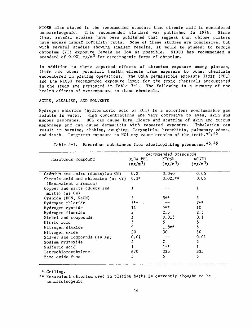
In addition to these reported effects of chromium exposure among platers, there are other potential health effects from exposure to other chemicals encountered in plating operations. The OSHA permissible exposure limit (PEL) and the NIOSH recommended exposure limit for the toxic chemicals encountered in the study are presented in Table 3-1. The follOWing is a summary of the health effects of overexposure to these chemicals.
ACIDS, ALKALIES, AND SOLVENTS
Hydrogen chloride (hydrochloric acid or HCL) is a colorless nonflammable gas soluble in water. High concentrations are very corrosive to eyes, skin and mucous membranes. HCL can cause burn ulcers and scarring of skin and mucous membranes and can cause dermatitis with repeated exposure. Inhalation can result in burning, choking, coughing, laryngitis, bronchitis, pulmonary edema, and death. Long-term exposure to HCl may cause erosion of the teeth. 44 ,45
Table 3-1. Hazardous substances from electroplating processes. 45 ,49
Hazardous Compound
Cadmium and salts (dusts)(as Cd) Chromic acid and chromates (as Cr)
(Hexavalent chromium) Copper and salts (dusts and mists) (as Cu)
Cyanide (KCN, NaCN) Hydrogen chloride Hydrogen cyanide Hydrogen fluoride Nickel and compounds Nitric acid Nitrogen dioxide Nitrogen oxide Silver and compounds (as Ag) Sodium hydroxide Sulfuric acid Tetrachloroethylene Zinc oxide fume
* Ceiling.
Recommended Standards OSHA PEL NIOSH ACGIH (mg/m3) (mg/m3) (mg/m3)
0.2 0.1*
1
5 7** 11 2 1 5 9 30 0.01 2 1 670 5
0.040 0.025**
5**
5** 2.5 0.015 5 1.8** 30
2 1** 335 5
0.05 0.05
1
5 7** 10 2.5 0.1 5 6 30 0.01 2 1 335 5
** Hexavalent chromium used in plating baths is currently thought to be noncarcinogenic.
16
Hydrogen fluoride (hydrofluoric acid) liquid or vapor is a primary irritant of the eyes, skin, mucous membranes and lungs, and can produce chemical and dermal burns; it can also cause deep-seated burns of the eye and eyelids. Chronic exposure may result in nose bleeds. Fluoride burns can result in systemic poisoning by absorption of fluoride through the skin. Inhalation of high levels of elemental or acid fluorine can cause bronchospasm, pulmonary edema, gastrointestinal symptoms, chest pain, lung damage, and death. Long-term exposure to lower concentrations of hydrogen fluoride vapor may effect changes in the bones. 44 ,45,46,47
Nitric acid is a suffocating odor. pulmonary edema; corrosi ve nature
colorless, yellow or red fuming liquid with an acrid, It causes eye, mucous membrane and skin irritation; delayed
pneumoni tis; bronchitis, and dental erosion. I ts extremely can produce burns and ulcers of the skin, eye, and mucous
membranes.
Nitrogen dioxide is a dark brown gas that can irritate the eyes and nasal passages and produce an acid taste. Acute exposures may produce death preceded by symptoms of weakness, a cold feeling, nausea, abdominal pain, coughing, severe cyanosis, accelerated heart action, and convulsions. In some cases, nitrogen dioxide may produce dyspnea, cyanosis, vomiting, vertigo, and unconsciousness without pulmonary edema.
Nitrogen oxide (or nitric oxide) is a colorless gas that is rapidly oxidized in the presence of oxygen. Because it oxidizes to other oxides of nitrogen such as nitrogen dioxide (which is a more serious hazard), it is a significant contaminant when found in the workplace. Methemoglobinemia may be caused by nitrogen oxide. 44 ,45,46,48
Sodium hydroxide (caustic soda) is a white solid, soluble in water, and can be inhaled as a dust or mist. As a solid, dust, mist or solution it can irritate t he nose, burn the eye or skin, cause temporary loss of hair, and produce pneumonitis. Sodium hydroxide is a strong alkali and is very corrosive to body tissue. Chronic exposure to dilute solutions may result in dermatitis. Effects are limited to local tissue damage. 44 ,45,49
Sulfuric acid is a colorless, odorless liquid soluble in water and alcohol. Concentrated sulfuric acid can cause rapid damage to mucous membranes, is exceedingly dangerous to the eyes, and can burn and char the skin and mouth. Diluted sulfuric acid is irritating to the eyes, nose, throat, and skin and may cause scarring of the skin and blindness. Inhaled sulfuric acid can cause etching of dental enamel and edema of the lungs and throat. Chronic exposure can lead to health problems such as emphysema and rhinorhea. 44 ,45,49
Tetrachloroethylene (perchloroethylene or "perc") is a clear colorless liquid which can cause dermatitis, headaches, fatigue, dizziness, nausea, drowsiness, and anesthetic death. It causes depression of the central nervous system, and also eye, nose, and throat i rri ta tion. Long-term exposure to tetrachloroethylene may cause skin irritation and damage the liver and kidneys.44,45,49
17

METALS AND SALTS
Cadmium and its salts can be inhaled or ingested. Cadmium dust when inhaled in sufficient quantity can produce cough, tight chest, substernal pain, chills, sweating, shortness of breath, and weakness. Cadmium compounds are readily absorbed by inhalation. Symptoms which may take several hours to develop usually begin with a slight irritation of the upper respiratory tract. Cadmium exposure is reported to cause an increased incidence of prostate cancer in men, and chronic exposure may cause loss of smell, emphysema, kidney damage, and mild anemia. 44 ,45,49
Copper salts, including copper sulfate dust or mist and cuprous chloride dust, can irritate the upper respiratory tract, cause congestion of the pharynx and cause a metallic taste; cause irritation, discoloration, and damage to the eye; and contact with the skin can result in itching, erythema, and dermatitis. Copper salts can also produce salivation, nausea, vomiting, gastric pain, hemorrhagic gastritis and diarrhea if introduced into the gastrointestinal tract. 44 ,45,30
Cyanide and hydrogen cyanide, the cyanides of principal concern, include hydrogen cyanide (HCN) and simple salt s of cyanide--e. g., sodium, potassium, and copper cyanide--which may come in contact with an acid releasing HCN gas. HCN when inhaled or cyanide salts when ingested can cause immediate collapse. High concentrations of cyanides can cause death due to chemical asphyxia at the cellular level and cessation of respiration. Lower concentrations can cause dizziness, headaches, weakness, confusion, nausea, and vomiting. Other effects are slow gasping respiration and eye and skin irritation. HCN gas has a bitter almond odor and can cause nose and upper respiratory tract irritation, while HCN liquid which is colorless or pale blue, may irritate the eye. Reports of disease from long-term exposure to cyanide were not found. 44 ,45,46
Nickel metal and compounds may produce sensitization dermatitis, allergic asthma, pneumonitis, and cancer of the lung and nasal cavities. A dermatitis known as "nickel itch" can result from nickel plating exposure. It can irritate the fingers, wrists, and arms and then spread to the rest of the body. About one-third of exposed workers have a natural immunity to "nickel itch." Nickel and nickel salts can also irritate the conjunctiva of the eye and in animal studies have been shown to affect the muscle, heart, brain, liver, and kidney. NIOSH has recommended that the permissible exposure for nickel be reduced to 0.015 mg/m3 and that nickel be treated as an occupational carcinogen. 44 ,50,5l
Silver and its compounds may cause discoloration and darkening of the eyes, nose, throat, and skin. Silver and its compounds are highly cumulative once they enter the body and can lead to permanent pigmentation of the skin and eyes. Fingernails, toe nails, and covered parts of the body can also be discolored. Silver nitrate is highly corrosive and can cause burns to the eyes and skin with possible permanent eye damage. 44 ,45
Zinc oxide (ZnO) can cause dermatitis known as "oxide pox." It appears as a red papule with a central plug which develops into a pustule that itches
18

intensely. Metal fume fever is the only major systemic effect from exposure to zinc oxide (fume or respirable dust). Symptoms of the fever include a sweet or metallic taste in the mouth, dry throat, cough, fatigue, and pain in the muscles and joints. This then can lead to a fever of 102-104 of and shaking chills. Disease caused by the zinc metal ion was not found in the literature. 44 ,46,48
19
IV. LITERATURE REVIEW OF PLATING PROCESS CONTROLS
Several methods for controlling chromic acid mist during plating operations have been described in the literature. These include floating plastic balls or chips, various chemical mist suppressants, tank covers, and several types of local exhaust ventilation.
Reports on effectiveness of control methods for chrome plating begins with Bloomfield and Blum12 in 1928. They report on a survey of six plants with a total of 22 chrQme plating tanks. Six of the tanks had single-sided exhaust, ten of the tanks had two-sided exhaust, and six had four-sided exhaust. Data are included for several tanks under differing operating conditions. A tank with single-sided exhaust and a control distance of 12 in. had chromium levels of 2.60 to 3.59 mg/m3 with the ventilation off; levels of 1.27 to 1.60 mg/m3 with an exhaust rate of 75 cfm/ft2; and levels of "0" mg/m 3 with an exhaust rate of 283 cfm/ft2. A second tank with single-sided exhaust and a control distance of 20 in. had chromium levels of 0.69 mg/m 3 with an exhaust rate of 30 cfm/ft2; levels of "0" mg/m 3 with an exhaust rate of 50 cfm/ft2; and levels of "0" to 2.20 mg/m 3 with an exhaust rate of 115 cfm/ft2. A third tank with single-sided exhaust and a control distance of 42 in. had chromium levels of 1.77 mg/m3 at an exhaust rate of 24 cfm/ft2. A tank with a two-sided centerline exhaust and a control distance of 18 in. had chromium levels of 0.06 mg/m3 with an exhaust rate of 128 cfm/ft2. One tank with four-sided exhaust and a control distance of 25 in. had chromium levels of 0.78 mg/m 3 with an exhaust rate of 9 cEm/ft 2 and 0.15 mg/m 3 with an exhaust rate of 40 cfm/ft2. A second tank with four-sided exhaust and a control distance of 18 in. had chromium levels of 2.90 mg/m3 with the ventilation off and 0.20 mg/m 3 with an exhaust rate of 46 cfm/ft2. The author concludes that with properly designed local exhaust, it is possible to control chromium levels to less than 0.05 mg/m 3 • He recommends lateral one- to twa-inch slots, with a slot velocity of 2,000 fpm and a maximum control distance of 18 in. The plating solution should be kept at least eight inches below the slots to avoid solution being drawn into the slots.
Riley and Goldman52 in 1937 reported on an evaluation of chrome plating controls. Two plating tanks with two-sided exhaust were evaluated under differing conditions. One tank with a control distance of 30 in. had chromium levels of 1.44 mg/m3 with ventilation off and a level of 0.020 mg/m3 with an exhaust rate of 100 cfm/ft 2 • The second tank with a control distance of 24 in. had a chromium level of 1.46 to 1.91 mg/m 3 with the ventilation off; 0.58 mg/m3 with an exhaust rate of 37.5 cfm/ft2; and 0.018 mg/m3 with an exhaust rate of 112 cfm/ft2. They recommend a minimum exhaust rate of 100 cfrn/ft2 in addition to the earlier recommendations of Bloomfield and Blum12 •
In 1944, Gresh17 reported on an evaluation of controls for an anodizing tank that used 5 percent chromic acid solution. The tank was fully enclosed with three doors for access to the tank. The enclosure which was exhausted at the top provided adequate control when the doors were closed, but allowed worker over-exposure when the doors were opened to gain access to the work. Chromium
20

levels were 0.62 mg/m3 with an exhaust rate of 120 cfm/ft 2 ; 0.48 mg/m3
with an exhaust rate of 122 cfm/ft 2 ; 0.22 mg/m 3 with an exhaust rate of 134 cfm/ft2 and 0.05 mg/m3 with an exhaust rate of 148 cfm/ft2. The ventilation was then redesigned to provide lateral exhaust slots inside the enclosure six in. above the solution level. Chromium was not detected with exhaust rates of 134 to 162.5 cfm/ft2 after this modification. He also recommended moisture collectors for the exhaust to prevent erO} mist escape to the outside and potential reentry into the plant. Molos~3, in 1947, reported on a test of the use of floating plastic chips to reduce Cr03 emissions from chrome plating tanks. The test was carried out by W. P. Davis at the Pensacola Naval Air Station. The tank used for the tests had two-sided exhaust with an exhaust rate of 170 cfm/ft2, and was screened off by canvas on all four sides to prevent interference by cross drafts. Two and one-half pounds of spray reducer chips per ft 2 of surface area were used. Samples collected eight inches above the solution level showed 0.01 to 0.03 mg/m3 of chromium with the chips in use and 0.21 to 0.26 mg/m3 without the chips. Levels of 8.3 to 8.8 mg/m 3 were found when the chips were used without ventilation. Chromium concentration had also been reported to vary inversely with the thickness of the layer of plastic chips. The maximum practical thickness of the layer was four inches. In actual plant evaluations, chromium levels in the workers' breathing zone were below detection limits in all cases where floating plastic chips were used in conjunction with local exhaust. At one plant using only the chips, worker exposures of 1.0 to 1. 6 mg/m3 were measured. The author recommends the use of floating plastic chips to reduce loss of Cr03 solution and reduction of worker exposure, but only in conjunction with local exhaust.
The use of chemical additives to control Cr03 emissions was studied by Silverman and ThomsonS4 and reported in 1948. Performance of a commercially available additive, No-Cro-Mist, possibly on aqueous solution of a fatty acid, was studied with a model plating bath provided with a canopy hood which extended to SO mm of the bath edges. An exhaust rate of 550 cfm/ft2 was used. Air samples were collected in the exhaust duct. Chromium levels of 0.031 mg/m3 to 0.088 mg/m 3 were measured without the additive and 0.0002 mg/m3 just after the additive was added. Over a period of five hours, the levels gradually increased to 0.047 mg/m3 • The amount of control was found to vary with the surface tension. The authors concluded that the agent helped control Cr03 emissions, but should be used along with local exhaust ventilation.
Stern et alS5 , in 1949, reported on an evaluation of the use of plastic beads in chrome plating tanks. Two types of beads were tested in six chrome plating tanks with and without ventilation. With no ventilation, chromium breathing zone air levels near the tanks ranged from 0.14 to 2.96 mg/m3 .
With local exhaust ventilation haVing exhaust rates of 90 to 138 cfm/ft2 and using no plastic beads, chromium levels of less than 0.0005 to 0.27 mg/m 3
were measured. With both the ventilation and the ~lastic beads in use, chromium levels of less than 0.0005 to 0.005 mg/m were measured. The authors recommended a minimum exhaust rate of 120 to 150 cfm/ft 2 even when plastic beads were used.
21

Hama, et a156 reported in 1954 on an evaluation of another chemical additive, Zeronist--a fluorocarbon chain compound. The evaluation was carried out in four decorative chrome plating plants. Five different tanks with ventilation off showed chromium breathing zone levels of 0.001 to 0.031 mg/m3 when the additive was used. One additional tank with an exhaust rate of 90 cfm/ft2 showed a breathing zone chromium level of 0.000 to 0.001 mg/m3 • Levels of chromium in the exhaust duct were shown to vary inversely with surface tension. It was concluded that use of this additive reduced chromium exposure, but no data were reported that showed level of control with and without the additive. It was recommended that local exhaust be used in addition to the additive for effective control.
Kleinfeld and Ross020, in 1965, reported on a medical study at a decorative chrome-plating plant. In the report, they note that breathing zone levels of chromium ranged from 0.09 to 0.73 mg/m3 prior to the installation of local exhaust ventilation. After local exhaust ventilation was installed, levels dropped to 0.002 to 0.005 mg/m 3 ; however, no information on the design or exhaust rate of the ventilation was given.
Hanslian, et a12l in their 1967 report on a medical study of Czech chrome plating workers included information on the levels of exposure and control techniques used. In one hard chrome plating plant, the anode bars were grouped around the cathode in such a way that fumes from within this area were not controlled by the local exhaust ventilation and total chromium breathing zone levels averaged 0.681 mg/m3 • In a decorative chrome plating plant, the anode bars were placed in front of the exhaust slots, obstructing air flow. In this case total chromium breathing zone levels averaged 0.482 mg/m 3 •
In one hard chrome plating plant, total chromium breathing zone levels as high as 26.3 mg/m 3 were measured. This process was uncontrolled due to the escape of fumes from the center part of hollow rotors that were being plated. The situation was corrected by the installation of tank covers and levels were controlled to an average of 0.052 mg/m 3 • Another decorative chrome-platin~ plant was able to maintain an average Cr breathing zone level of 0.023 mg/m through the use of a layer of a high boiling point liquid hydrocarbon as a mist suppressant in addition to ventilation. No indication was given in this report of the design' or exhaust rates of ventilation in use in any of the plants. It was observed that in plants where employees minimized time spent at or in the immediate Vicinity of the plating baths, workers had fewer health effects than workers at plants where this did not occur. Poor personal hygiene was also related to a higher incidence of health problems related to chromium exposure.
In 1969, Mitchel1 22 reported medical problems with workers near a chrome stripping tank. Breathing zone chromium levels were 0.57 mg/m 3 • After installation of local exhaust, levels were reduced to 0.005 mg/m 3 • No indication was given of the exhaust rate of the tank.
In a 1972 NIOSH health hazard evaluation report, Ramos and Flesch57
evaluated controls for a tin plating operation. A canopy hood, 18 to 24 in. above the plating solution was used for control. Air velocities at the hood ranged from 25 to 600 fpm. No hood or tank dimensions were reported so that
22

exhaust rate could not be calculated. It was stated that the hood was not effective in controlling exposures. Air levels of tin ranged from less than 0.01 mg/m3 to 1. 60 mg/m3 ; cyanide ranged from 0.14 to 1. 5 mg/m3 ; gaseous fluoride ranged from 0.17 to 0.59 mg/m 3 ; particulate fluoride ranged from 0.20 to 1.80 mg/m3 ; and hydrogen chloride ranged from 0.36 to 2.50 mg/m 3 .
Markel and Lucas25 in 1973 reported on another NIOSH health hazard evaluation of a decorative chrome plating operation. Chromium exposures were all 0.003 mg/m3 or less. No indication is given of the type or capacity of exhaust ventilation used. It was stated that the plant had tried various chemical mist control additives but they were not considered practical. A problem with several small explosions developed because these agents trapped hydrogen gas evolved from the bath. The use of these additives had been discontinued.
Also in 1973, Kramkowski 26 reported on a NIOSH health hazard evaluation of an automated zinc and nickel plating operation. Push-pull ventilation was used to control emissions from the plating tanks, but no tank or hood dimensions, or exhaust rates were given. Only the zinc plating line was in operation during the evaluation. Worker exposure to zinc oxide averaged 0.0024 mg/m3 ; total chromium averaged 0.0032 mg/m 3 ; cyanide averaged 0.0049 mg/m 3 ; nitric acid averaged 1.2 mg/m3 ; and hydrogen chloride averaged 0.0099 mg/m3. All of these were considerably below recommended standards.
Another NIOSH health hazard evaluation of automated nickel-chrome and zinc plating operations was reported in 1973 by Cohen and Kramkowski 28 • No indication of the tY2e of ventilation was given. Total chromium air levels averaged 0.0071 mg/m 3 ; chromium (VI) levels averaged 0.0029 mg/m\ nitrate levels averaged 0.0888 mg/m3 ; and chloride averaged 0.1607 mg/m j at the nickel-chrome plating lines. At the zinc plating lines, total chromium levels averaged 0.0001 mg/m 3 ; total chromiun (VI) levels averaged 0.0003 mg/m 3 ; zinc levels averaged 0.016 mg/m 3 ; phosphate levels averaged 0.0045 mg/m3 ; cyanide levels averaged 0.0057 mg/m3 ; nitrate levels averaged 0.0529 mg/m 3 ; and chloride levels averaged 0.0521 mg/m3 •
Zumwalde58- 67 , in 1973 and 1974, reported on a series of NIOSH surveys at chrome plating plants. The first plant, a hard chrome plating operation, used three tanks with two-sided local exhaust and one tank with single-sided local exhaust. A chemical mist suppressant was also used. The tanks had control distances of 24 in., 30 in., 28 in., and 18 in. and exhaust rates of 88, 70, 102, and 108 cfm/ft 2 , respectively. Worker exposures to chromium (VI) ranged from 0.0011 to 0.0486 mg/m 3•
The next plant evaluated also did hard-chrome plating in nine plating tanks equipped with two-sided exhaust. One-inch diameter polyethylene floating balls were used as an additional control technique. Control distances for the tanks ranged from 18 in. to 30 in. and exhaust rates ranged from 56 to 122 cfm/ft2. Worker exposures to chromium (VI) ranged from 0.0008 to 0.0096 mg/m 3 .
Another hard chrome plating plant that was evaluated had seven plating tanks with single-sided exhaust. A partial tank cover covering one-third of the
23

surface extended out from the local exhaust hood on all but one tank. The hood on this tank had two slots, one six inches above the other. Cont'rol distances ranged from 36 in. to 48 in. and exhaust rates ranged from 11 to 56 cfm/ft2. Worker exposure to chromium (VI) ranged from 0.0036 mg/m3 to 0.0660 mg/m3 •
A decorative chrome plating plant with two chrome plating tanks and three nickel plating tanks was also evaluated. No local exhaust ventilation was used, but a chemical mist suppressant was added to the tanks. Worker exposure to chromium (VI) ranged from 0.0002 mg/m3 to 0.0059 mg/m3•
The final plant was a decorative chrome plating operation with four nickel and one chrome plating tanks. No local exhaust ventilation was utilized; however, a chemical mist suppressant was added to the tanks. Worker exposure to chromium (VI) ranged from less than 0.0002 to 0.0090 mg/m3 •
Gilles and Philbin33 , in 1976, reported on a NIOSH hazard evaluation in a lead plating operation. Local exhaust ventilation with a capture velocity of 50 to 150 fpm was present, but the design and exhaust rate of the ventilation was not given. Worker exposure to lead was all less than 0.002 mg/m3 and exposure to fluorides ranged from 0.12 to 0.55 mg/m3•
Pryor35, in 1978, reported on a NIOSH hazard evaluation of a decorative chrome plating operation. The one plating tank used slot-type local exhaust ventilation with a slot velocity of 175 to 200 fpm. Again no design or exhaust rates were reported for the ventilation. Worker exposure to chromium (VI) were all less than 0.003 mg/m3 •
Also in 1978, Guillemin and Berode68 reported on an evaluation of the difference in worker exposure between decorative and hard chrome plating. Six hard chrome and six decorative chrome plating plants were surveyed. Eleven ventilated hard chrome plating tanks had exhaust rates ranging from 23 to 171 cfm/ft2 and chromium levels of 0.001 to 0.341 mg/m3 • Four unventilated hard-chrome tanks had chromium levels of 0.009 to 0.055 mg/m3 • Three ventilated decorative chrome-plated tanks had chromium levels ranging from 0.003 to 0.014 mg/m3 with exhaust rates of 23 to 72 cfm/ft2. Five unventilated decorative chrome plating tanks had chromium levels ranging from 0.001 to 0.003 mg/m3 • Four of these five tanks used chemical mist suppressants. The authors conclude that ventilation is not necessary when a chemical mist suppressant is used for decorative chrome plating. Ventilation was found to be necessary for hard chrome plating, even when floating balls were used as a mist suppressant.
In 1981, Ahrenholz and Anderson40 reported on a NIOSH health hazard evaluation of a hard chrome plating plant. Exhaust rates for the five plating tanks ranged from 49 to 282 cfm/ft2. Worker exposures to total chromium ranged from 0.009 to 0.011 mg/m 3 and exposure to chromium (VI) ranged from 0.003 to 0.006 mg/m3 •
Throughout this literature, the reports indicate that ventilation is necessary to control chromium emissions during hard-chrome plating. Floating plastic beads reduce chromium emissions, but are not sufficient controls by
24

themselves. As would be expected, as exhaust rate increases, there is a tendency for chromium emissions to be reduced. The need for local exhaust ventilation for decorative plating is less clear. There are some reports of adequate control through the use of chemical mist suppressants. These seem to be adequate to meet the NIOSH recommended standard of 0.025 mg/m3, but probably not the recommended standard of 0.001 mg/m3 for carcinogenic chromium (VI). Surveys of other types of plating indicated adequate control of materials other than chromium. Hard chrome plating appears to have the highest potential for hazardous exposure and, therefore, a need for controls.
25

v. STUDY METHODS
The various control measures were evaluated primarily by collecting environmental samples for potentially hazardous substances involved in the process and by measuring airflow around the operation. This section presents the sampling, analytical, and engineering evaluation methods used during the course of this study to measure workplace levels of airborne chemicals and to assess the effectiveness of control measures. Examples of good work practices and the use of protective equipment were also documented.
AIR SAMPLING
The purpose of air sampling was to obtain data about the effectiveness of a particular control measure to support observations and flow measurements. Prior to sampling, a study of the particular process and its control measures, as well as attendant conditions, was made to provide an understanding of the variables which could affect the sampling results. Basically, two different types of samples were taken:
1. Personal samples, filter casset tes, silica gel tubes, and charcoal tubes were clipped to the collar on the front side of the work shirt. This placed them in the breathing zone, only a few inches below the face, in a manner so as not to interfere with the worker's activities. This type of sample permitted an evaluation of the plater's potential exposure to airborne hazards from the plating operations being evaluated. The results of these 8-hour samples were directly compared to OSHA PELs and NIOSH recommended standards. By themsel ves, howeve r, personal samples did not always gi ve a di rec t indication of the performance of a particular control.
2. Area samples were placed at fixed locations around the plating tanks. Most of the area air samples were positioned close to an edge of one of the tanks, above the slot if located on a ventilated side. A few samples were placed directly above the surface of the tank to sample air before being substantially affected by the ventilation. The rest of the area samples were placed in the general room air. Since the workers move from one area to another, the area sample concentrations are not directly comparable to work-shift standards for employee exposure. It can, however, be informative to compare area concentrations with ceiling limits in order to identify areas of potentially high exposure (although not all such areas) where employees should be cautious about working for more than brief periods of time.
Sampling duration was based on the sensitivity of the analytical procedure and the estimated airborne concentration of contaminant to be sampled. Because low contaminant levels were expected in most cases, longer sampling times were generally used. Approximate full-shift samples were normally taken; however, when this was not possible or practical, shorter samples (3 to 4 hours) were taken. The extent of sampling was restricted to a period of 3 to 5 days for
26
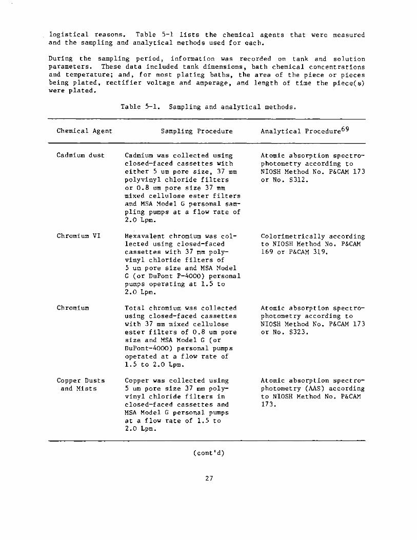
logistical reasons. Table 5-1 lists the chemical agents that were measured and the sampling and analytical methods used for each.
During the sampling period, information was recorded on tank and solution parameters. These data included tank dimensions, bath chemical concentrations and temperature; and, for most plating baths, the area of the piece or pieces being plated, rectifier voltage and amperage, and length of time the piece(s) were plated.
Chemical Agent
Cadmium dust
Chromium VI
Chromium
Copper Dusts and Mists
Table 5-1. Sampling and analytical methods.
Sampling Procedure
Cadmium was collected using closed-faced cassettes with either 5 urn pore size, 37 mm polyvinyl chloride filters or 0.8 urn pore size 37 mm mixed cellulose ester filters and MSA Model G personal sampling pumps at a flow rate of 2.0 Lpm.
Hexavalent chromium was collected using closed-faced cassettes with 37 mm polyvinyl chloride filters of 5 um pore size and MSA Model G (or DuPont P-4000) personal pumps operating at 1.5 to 2.0 Lpm.
Total chromium was collected using closed-faced cassettes with 37 mm mixed cellulose ester filters of 0.8 um pore size and MSA Model G (or DuPont-4000) personal pumps operated at a flow rate of 1.5 to 2.0 Lpm.
Copper was collected using 5 um pore size 37 mm polyvinyl chloride filters in closed-faced cassettes and MSA Model G personal pumps at a flow rate of 1.5 to 2.0 Lpm.
(cont'd)
27
Analytical Procedure69
Atomic absorption spectrophotometry according to NIOSH Method No. P&CAM 173 or No. 5312.
Colorimetrically according to NIOSH Method No. P&CAM 169 or P&CAM 319.
Atomic absorption spectrophotometry according to NIOSH Method No. P&CAM 173 or No. S323.
Atomic absorption spectrophotometry (AA5) according to NIOSH Method No. P&CAM 173.
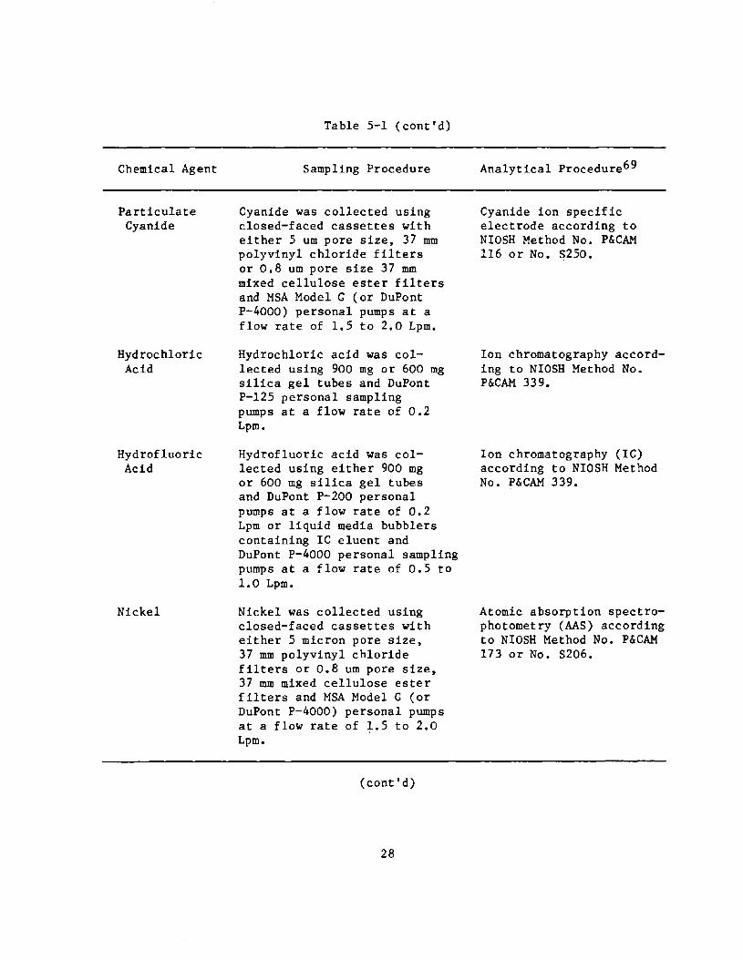
Chemical Agent
Particulate Cyanide
Hydrochloric Acid
Hydrofluoric Acid
Nickel
Table 5-1 (cont'd)
Sampling Procedure
Cyanide was collected using closed-faced cassettes with either 5 um pore size, 37 mm polyvinyl chloride filters or 0.8 um pore size 37 mm mixed cellulose ester filters and MSA Model G (or DuPont P-4000) personal pumps at a flow rate of 1.5 to 2.0 Lpm.
Hydrochloric acid was collected using 900 mg or 600 mg silica gel tubes and DuPont P-125 personal sampling pumps at a flow rate of 0.2 Lpm.
Hydrofluoric acid was collected using either 900 mg or 600 mg silica gel tubes and DuPont P-200 personal pumps at a flow rate of 0.2 Lpm or liquid media bubblers containing IC eluent and DuPont P-4000 personal sampling pumps at a flow rate of 0.5 to 1.0 Lpm.
Nickel was collected using closed-faced cassettes with either 5 micron pore size, 37 mm polyvinyl chloride filters or 0.8 um pore size, 37 mm mixed cellulose ester filters and MSA Model G (or DuPont P-4000) personal pumps at a flow rate of 1.5 to 2.0 Lpm.
(cont'd)
28
Analytical Procedure69
Cyanide ion specific electrode according to NIOSH Method No. P&CAM 116 or No. 5250.
Ion chromatography according to NIOSH Method No. P&CAM 339.
Ion chromatography (IC) according to NIOSH Method No. P&CAM 339.
Atomic absorption spectrophotometry (AAS) according to NIOSH Method No. P&CAM 173 or No. 5206.

Chemical Agent
Ni tric Acid
Potassium Hydroxide
Silver
Sodium Hydroxide
Sulfuric Acid
Table 5-1 (cont'd)
Sampling Procedure
Nitric acid was collected using either 900 mg or 600 mg silica gel tubes and DuPont· P-200 personal sampling pumps at a flow rate of 0.2 Lpm or liquid media bubblers containing IC eluent and DuPont P-4000 personal sampling pumps at a flow rate of 1.0 Lpm.
Potassium hydroxide was collected using closed-faced cassettes with 1.0 um pore size, 37 mm Teflon filters and MSA Model G personal sampling pumps at a flow rate of 1. 5 Lpm.
Silver was collected using closed-faced cassettes with 5 micron pore size, 37 mm polyvinyl chloride filters and MSA Model G (or DuPont P-4000) personal sample pumps at a flow rate of 1.5 Lpm.
Sodium hydroxide was collected using closed-faced cassettes with 1 um pore size Teflon filters and MSA Model G (and DuPont P-4000) personal sampling pumps at a flow rate of 1.5 Lpm.
Sulfuric acid was collected using 900 mg or 600 mg silica gel tubes and DuPont P-200 (or DuPont P-4000) personal pumps operating at 0.2 Lpm.
(cont'd)
29
Analytical Procedure69
Ion chromatography according to NIOSH Method No. P&CAM 339.
Atomic emission spectrophotometry according to UB~L Method No. MI 340.
Atomic absorption spectrophotometry according to NIOSH Method No. P&CAM 173
Back titration according to NIOSH Method S381 or atomic emission spectrometry for total sodium according to UBTL Method MI 340.
Ion chromatography according to NIOSH Method No. P&CAM 339.

Chemical Agent
Te t rac hloreethylene
Zinc
Table 5-1 (cont'd)
Sampling Procedure
Tetrachloroethylene was collected using 150 mg charcoal tubes and MDA 808 accuhaler pumps at a flow rate of approximately 0.1 Lpm.
Total zinc was collected using closed-faced cassettes with 1 um pore size, 37 mm Teflon filters and MSA Model B (or DuPont P-4000) personal sampling pumps at a flow rate of 1.3 to 1.5 Lpm.
Analytical Procedure69
Gas chromatography according to NIOSH Method No. P&CAM 5-335 (modified)
Atomic absorption spectrophotometry according to NIOSH Method No. P&CAM 173
Finally, the hard chromium plating results from the study were analyzed with a statistical model using a least squares regression analysis to determine the relationship between key independent variables such as exhaust rate and the resulting concentrations of chromium and sulfuric acid. Models were formulated including variables and combinations of variables which were thought to best represent the major factors associated with controlling emissions from chromium plating operations. A number of these models were tested using a general linear model procedure (PROC GLM) within the Statistical ~nalysis System* software to ascertain which parameters accounted for most of the variablity in the ambient contaminant concentration data. This analysis was hampered by the inability in our study to control or account for all the independent variables, by the nonlinear relationships of many of the variables, and by the small data sets inherent to our control technology field surveys.
AIRFLOW MEASUREMENTS
The effectiveness of engineering controls was determined largely by assessing airflow around the process, exhaust air volumes, and general ventilation in the building. For push-pull ventilation systems, the push air supply volume was also measured.
During the course of the assessment, control configurations were sketched or a photograph was taken. Measurements of exhaust and make-up air volumes were also made where possible. Two measuring techniques were used to determine exhaust airflow rates from hoods:
*SAS Institute Inc., Box 8000, Cary, North Carolina 27511
30
1. Duct traverses were made to determine total exhaust volumes.
2. Face velocities were measured to determine the approximate indraft velocities, as well as total exhaust volumes when duct traverses were not possible.
Total airflow in the ducts was measured using either a pitot tube or a hot-wire anemometer. Air velocities around each tank were measured using either a Sierra Model 440, a Kurz Model 441, or a TSI 1650 hot-wire anemometer. Slot air velocity measurements were taken at approximately one-foot intervals. Two readings were taken at each interval, one for the top half of the slot and one for the bottom half. Control velocities were measured in the vertical plane at the front of each tank with one-sided exhaust hoods. Smoke tubes were used to qualitatively evaluate local exhaust ventilation.
31

VI. RESULTS
Occupational exposures can be controlled by the application of a number of well-known principles, including engineering measures, work practices, personal protection, and monitoring. A combination of measures from one or more of the above categories is usually employed to provide ample worker protection. For the purposes of this report, the categories will be treated separately.
ENGINEERING CONTROLS
Engineering controls, which are designed into or around the production processes, are a major part of most control systems. The effectiveness of the engineered control measures employed in the plating operations surveyed was evaluated with air sampling and airflow measurements. A number of different plating operations were observed during the course of the study.
A total of over 1100 samples were taken for 16 substances during the 9 surveys. The sampling results have been averaged over the sampling period for eac h of the approximately 100 locations. Assuming a log-normal dist ri bution of the data, the logarithm of each concentration was used in all mathematical operations and the results were transformed back to concentration values for reporting. For samples reported below the analytical limit of detection, the concentration value was taken to be half that calculated using the detection limit as the amount of substance collected. In addition to selected tables in the body of the report, the sampling results are tabulated by substance and type (personal or area) in Appendix A. Location descriptions include a plant number and a letter for each plater or tank in the plant.
Engineering control technology was assessed for the following processes: hard chromium, silver, cadmium, copper, nickel, and zinc plating; chromium and nickel stripping; and acid, caustic, and ·solvent cleaning. This report emphasizes hard chromium plating because of the significance of the hazards involved and the need for control methods in hard chromium plating operations.
Hard chromium plating
Of the 64 plating and cleaning tanks evaluated in the study, 31 involved hard chromium plating. These tanks covered a broad range of sizes, configurations, exhaust rates, and plating activity. Table 6-1 gives the ranges of selected parameters for the chromium plating tanks. Exhaust rate, which is the ratio of the volumetric flow rate being drawn though the local exhaust ventilation system to the surface area of the tank, is a major factor affecting the airborne concentrations of chromium and sulfuric acid, as is avoiding unwanted air currents across the surface of the tank.
32

Table 6-1. Range of values for selected plating tank parameters.
Parameter
Tank Width (in)
Tank Length (in)
Tank Volume (gal)
Chromic Acid Concentration (oz/gal) • Bath Temperature ( F)
2 Exhaust Rate (cfm/ft )
Average Daily Plating Load (Amp-hr)
Range of Values
24 60
36 432
27 432
25 40
90 142
55 250
160 56000
Eight of the hard chromium plating tanks which were evaluated were ventilated only on one side; however, they· were fitted with either full covers or push-pull ventilation or both. Three of these had three full-length slots on the one side. Four of the tanks had full covers, including two of the ones with the three-slot hoods. All but two tanks (the two with one-slot hoods and full covers) had push-pull ventilation.
Eighteen of the hard chromium tanks were ventilated on two (opposite) sides. One of these was fully covered during one day of the survey; five others had partial covers. Examples of several two-sided hard chromium plating tanks are shown in Figures 6-1, 6-2, 6-3, and the schematic of a typical hard chromium plating tank is drawn in Figure 6-4.
The other five hard chromium tanks in our study had ventilation on three sides. One of these was fully covered. Figure 6-5 is a photograph of one of the uncovered tanks.
In general, the control measures were effective in controlling worker exposures within most current and proposed standards. In fact, 5 of the 7 personal samples for (total) chromium and 39 of 47 samples for sulfuric acid were below detectable limits and were typically two orders of magnitude below the NIOSH recommended and the current OSHA standards. For total chromium, the highest concentration value was less than 2 percent of the standard. For sulfuric acid, some concentrations were close to the 1 mg/m3 standard.
For hexavalent chromium, no daily worker exposures exceeded the current recommended NIOSH time-weighted average level of 0.025 mg/m3 for noncarcinogenic hexavalent chromium. Howeve r, under the conditions at the time of our surveys, some plants would not meet the NIOSH recommended standard of 0.001 mg/m3 which may be established if hexavalent chromium from plating operations is determined to be carcinogenic.
33

Figure 6-1. Hardchrome plating tank with two-sided ventilation.
Figure 6-2. Hardchrome plating tank with two-sided ventilation.
34
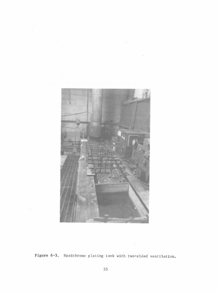
•
Figure 6-3 . Hardchrome plating tank with two-sided ventilation.
35
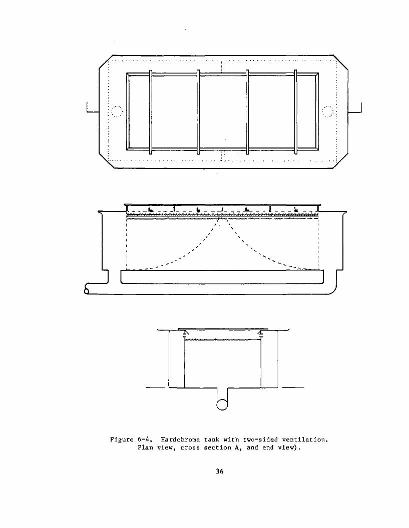
.......
(
. .. : ...
__ ... _ _ _ _ _ _ " _ _ _ _ _ _ -"_ _ _ _ Ik i" , , " , ""}2',VT,;:? ", "' J , ,. ) , ;1! r,,!
01 Is I f • _______ --"'- _ c..
I . I
.l'\
r-. '--'
, \ ,
, ,
...
---
/.L
]
Figure 6-4. Hardchrome tank with two-sided ventilation. Plan view, cross section A, and end view).
36

Figure 6-5. Tank - three-sided ventilation.
Some of the control system applications may be judged inadequate in that some of the average tank concentrations exceeded the NIOSH recommended ceiling limit of 0.05 mg/m3 for noncarcinogenic hexavalent chromium, and a few of these were also greater than the OSHA ceiling limit of 0.1 mg/m3 • Figure 6-6 shows that the average concentration of the air around at least one tank in each of three different groups--one-sided ventilation with push-pull, two-sided ventilation, and three-sided venti1ation--exceeded both of these ceiling limits. In addition, none of the tanks had average area concentrations less than the 0.001 mg/m3 ceiling limit which NIOSH would recommend for hexavalent chromium from plating operations if it is determined to be carcinogenic. The fact that an area concentration exceeds a ceiling limit for personal exposure does not mean that a worker has been overexposed, but rather that that there were areas around these tanks where an employee could have been exposed to concentrations in excess of ceiling limits if his breathing zone was near one of these areas for a sufficient period of time. This may not be evident from the individual time-weighted average exposure data.
37

2
10 "-
'" 05 E c-Q 02 11
0.1 ~ u
005 c c u E 002 ~
E e 0.01 .c '-' C
0.005 .. g 0.002 ., .. 0001 J:
00005
o cc
o cc
c
LEGE NO: • 1 - SIded With F'ull Cover
A
6 I-SIded With Push/Pull But No Cove, ... I - Su:led With Push/Pull 6. Full Cover [] 2 - Sided Wilhout Cover ~ 2- Sided Wilh ParlialCower • 2-S.ded WifhFullCo'ter o :3 Sided WllhOl.JI CO'e<er • "-Slded Wnh full Cover
OSHA PEL (CEILING LIMIT)
---;--O--~D-----'N~;-;;~;M~E~~D~EI~;'-;'~~T FOR
o A NON-CARCINOGENIC HEXAVALENT CHROMIUM
A A o
.a. • o
• c 0 --.-------.- -P---_._._-_.--'I_-'- NIOSH RECOMMENDED CEILING LIMIT FOR CARCINOGENIC HEXAVALENT CHROMIUM
2Q 40 60 SO 100 120 140 160 leo 200 220 240 260
EXHAUST- RATE, elm/fl'
Figure 6-6. Average hexavalent chromium concentrations with respect to exhaust rate for all chromium plating tanks
compared to pertinent ceiling limits.
As a general rule, if the hexavalent chromium concentration is controlled within permissible limits, the concentrations of total chromium and sulfuric acid will be also. Therefore, the following discussions will deal mostly with hexavalent chromium.
The generation of acid mist from the bath is directly related to plating workload. This was verified for one tank on which samples were collected directly over the surface of the plating bath. Table 6-2 shows that the amounts of chromium (both hexavalent and total) collected on the filters are roughly proportional to the sum of the products of the rectifier amperage settings and the time the pieces plated at each setting. This was not true for the other sampling sites on this tank or for the other tanks for which no samples were collected over the surface.
Table 6-2. Relationship of plating load and tank emissions for one tank.
Chromium Emissions Emission/Load Ratio
Day Plating Load Hexavalent Total Hexavalent Total Amp-hr mg mg mg/amp-hr mg/amp-hr
1 3360 3.8 3.8 0.0011 0.0011
2 1820 2.2 2.8 0.0012 0.0015
3 1500 1.5 1.6 0.0010 0.0010
38
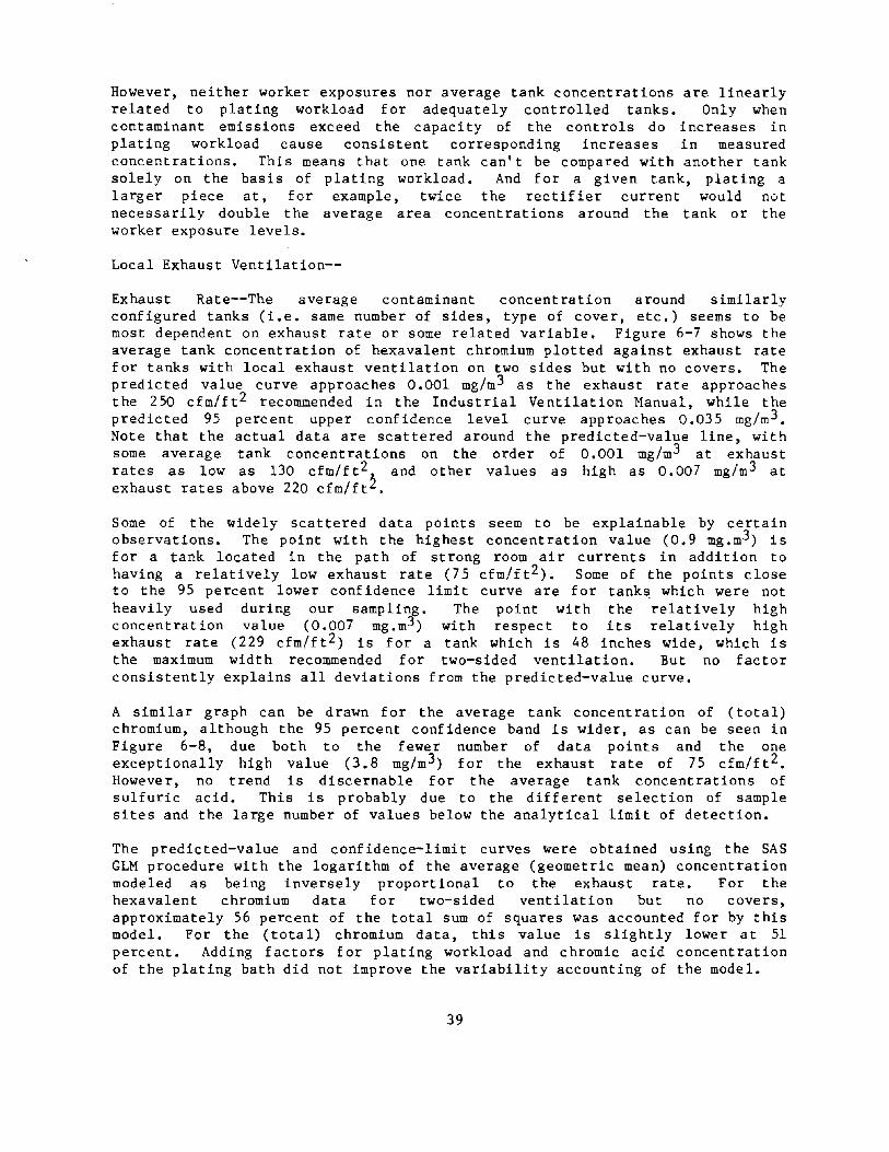
However, neither worker exposures nor average tank concentrations are linearly related to plating workload for adequately controlled tanks. Only when contaminant emissions exceed the capacity of the controls do increases in plating workload cause consistent corresponding increases in measured concentrations. This means that one tank can't be compared with another tank solely on the basis of plating workload. And for a given tank, plating a larger piece at, for example, twice the rectifier current would not necessarily double the average area concentrations around the tank or the worker exposure levels.
Local Exhaust Ventilation--
Exhaust Rate--The average contaminant concentration around similarly configured tanks (i.e. same number of sides, type of cover, etc.) seems to be most dependent on exhaust rate or some related variable. Figure 6-7 shows the average tank concentration of hexavalent chromium plotted against exhaust rate for tanks with local exhaust ventilation on two sides but with no covers. The predicted value curve approaches 0.001 mg/m3 as the exhaust rate approaches the 250 cfm/ft 2 reco=ended in the Industrial Ventilation Manual, while the predicted 95 percent upper confidence level curve approaches 0.035 mg/m 3 • Note that the actual data are scattered around the predicted-value line, with some average tank concentrations on the order of 0.001 mg/m 3 at exhaust rates as low as 130 cfm/ft 2 J. and other values as high as 0.007 mg/m 3 at exhaust rates above 220 cfm/ftL.
Some of the widely scattered data points seem to be explainable by certain observations. The point with the highest concentration value (0.9 mg.m3 ) is for a tank located in the path of strong room air currents in addition to having a relatively low exhaust rate (75 cfm/ft 2 ). Some of the points close to the 95 percent lower confidence limit curve are for tank!;l which were not heavily used during our sampling. The point with the relatively high concentration value (0.007 mg.m3 ) with respect to its relatively high exhaust rate (229 cfm/ft 2) is for a tank which is 48 inches wide, which is the maximum width reco=ended for two-sided ventilation. But no factor consistently explains all deviations from the predicted-value curve.
A similar graph can be drawn for the average tank concentration of (total) chromium, although the 95 percent confidence band is wider, as can be seen in Figure 6-8, due both to the fewer number of data points and the one exceptionally high value (3.8 mg/m 3 ) for the exhaust rate of 75 cfm/ft2. However, no trend is discernable for the average tank concentrations of sulfuric acid. This is probably due to the different selection of sample sites and the large number of values below the analytical limit of detection.
The predicted-value and confidence-limit curves were obtained using the SAS GLM procedure with the logarithm of the average (geometric mean) concentration modeled as being inversely proportional to the exhaust rate. For the hexavalent chromium data for two-sided ventilation but no covers, approximately 56 percent of the total sum of squares was accounted for by this model. For the (total) chromium data, this value is slightly lower at 51 percent. Adding factors for plating workload and chromic acid concentration of the plating bath did not improve the variability accounting of the model.
39
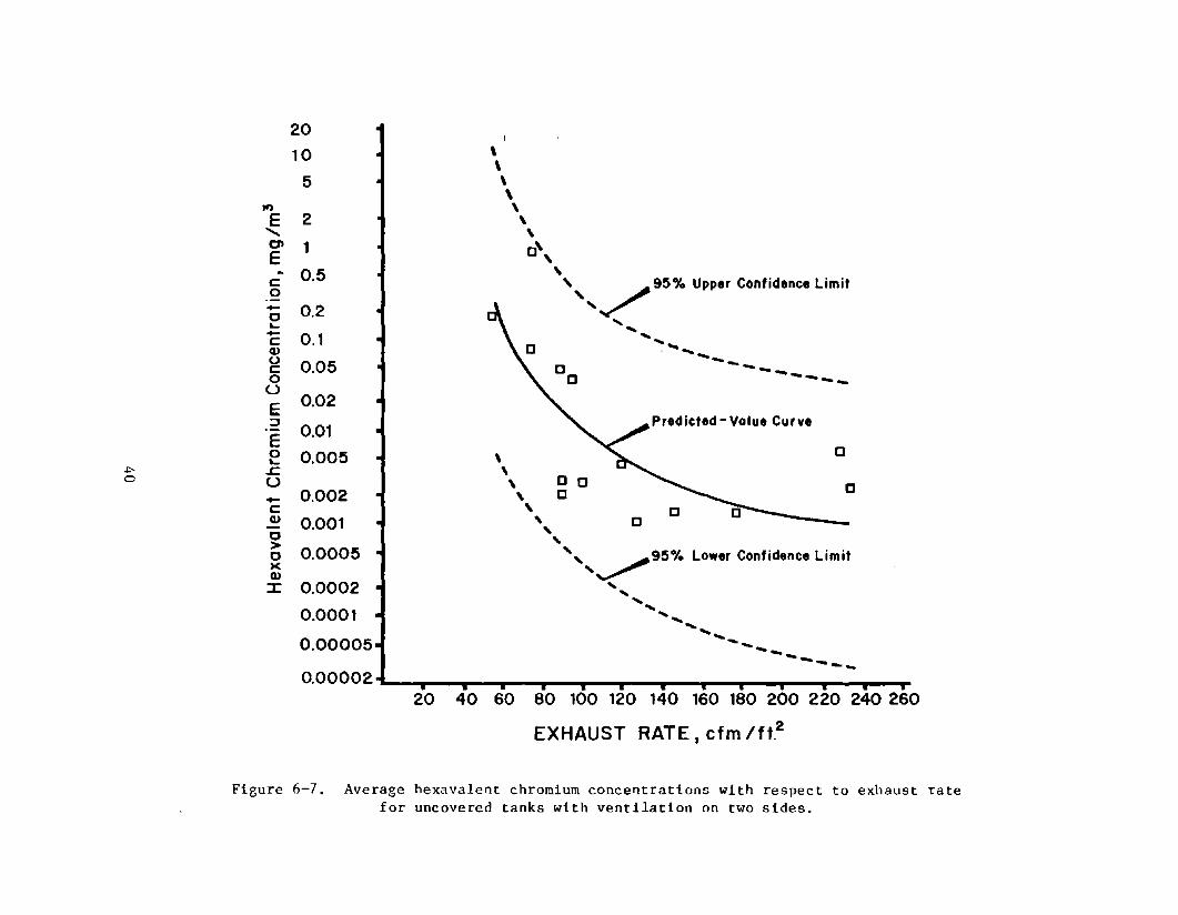
20 40 60 80 100 120 140 160 180 200 220 240 260
EXHAUST RATE, cfm Ift.2
Figure 6-7. Average hexavalent chromium concentrations with respect to exhaust rate for uncovered tanks with ventilation on two sides.
"" ......
I<l
E ..... 01 E ~
c 0 -c ~ -c Q) (.)
c 0 u E :::::J
E 0 ~
r. U
0 -~
20
10
5
2
1
0.5
0.2
0.1
0.05
0.02
0.01
0.005
0.002
0.001
0.0005
0.0002
0.0001
\ \ \ \ ,
o " " 95% Upper Confidence Limit Curve
" ..... J
, ,
c
, , , "
------ ----.. .... --.,
c Predicted-Value Curve
""'0
" 95% Lower Confidence Limit Curve ,,~
' ..... .... .......... ........ ........
QOOOOl ~~---T--~--~~~-'---T--~--~~~-'''''--~-T--~ 20 40 60 80 100 120 140 160 180 200 220 240 260
EXHAUST RATE .cfm/ft~/in.
Figure 6-8. Average total chromium concentrations with respect to exhaust rate for uncovered tanks with ventilation on two sides.
Slightly more of the variation (64 percent) in the hexavalent chromium data for two-sided ventilation with no covers can be accounted for by dividing the exhaust rate by the distance for ventilation control--which for one-sided ventilation is the distance from the ventilation slot to the opposite edge of the tank, for two-sided ventilation is half the distance between the two slots, and for three-sided ventilation is the smaller of the distance across the tank from the middle slot and half the distance between the flanking slots. This indicates that for wider tanks, higher ratios of local exhaust ventilation flow rate to tank surface area are desired. Graphically, the data for exhaust rate divided by the ventilation control distance, plotted in Figure 6-9, is similar to Figure 6-7.
Number of Sides Ventilated--A significant difference in the average tank area concentration is not evident with respect to the number of sides ventilated. In fact--for reasons not obvious from exam1n1ng the numerical data--the highest average concentration belongs to a tank with ventilation on three sides, and the lowest average concentration for uncovered tanks is for one with two ventilated sides.
Looking a t the dependence on exhaust rate just f or tanks wi th no covers, Figure 6-10, the observed values for tanks with only one ventilated side (all with push-pull ventilation) are all above the predicted-value line for two-sided tanks and three of the four points roughly follow the form of the curve. On the other hand, the data points for tanks with ventilation on three sides are widely scattered with three of the five points lying outside the 95 percent confidence band. The data for exhaust rate divided by the ventilation control distance, Figure 6-11, are similar except that three of the· four points for one-sided push-pull ventilation are below the predicted-value curve.
Other Factors--Although no single variable consistently explains the observed values of the data points with respect to either the other tanks in the same grouping or a particular concentration limit value, certain trends are present. The uncovered tanks with two-sided ventilation for which the average area concentrations of hexavalent chromium were less that 0.05 mg/m 3 were less than 36 inches wide or had relatively high slot velocities (greater than 1200 ft/min) or both--yielding slot velocity per inch of ventilation control distance values of 48 or greater. All had exhaust rates greater than 80cfm/ft 2 (greater than 38 percent of the value recommended in the Industrial Ventilation Manual) and exhaust rate per ventilation control distance values greater than 4 cfm/ft 2/in. The two tanks in this group with relat i vely high concent rations considering thei r "good" parameters were bot h from a plant which had otherwise poor ventilation.
On the other hand, the uncovered tanks with two-sided ventilation whose average area concentrations were equal to or greater than 0.05 mg/m3 are all wide tanks (44 - 48 inches) with exhaust rates less than 100 cfm/ft2 (less than 40 percent of the recommended value) and exhaust rate per ventilation control distance values less than 4 cfm/ft 2/in. All but one of these tanks had relatively high plating workloads and low slot velocities. The one tank in this group which had daily plating loads less than 2000 amp-hr and a slot velocity greater than 1000 ft/min was the tank situated in strong crossdrafts.
42
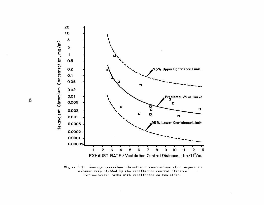
If)
E ....... CI E ~
t: 0 +-0 ... +-t: Q) u c:: 0 U
E ~
E "" 0 w ...
.r. U +-c:: Q)
0 > 0 )( Q)
:r::
20
10 \
5 \ \ \
2 \ \
1 ~,
0.5 , ,
... ... 0.2 ... ............. /95% Upper Confidence Limit.
0.1 ... -0.05 ------C - ... _--- -. 0.02
0.01 \ Pr~dicted-Value Curve \
0.005 \ C \ C ,
C 0.002 , , C C 0.001 ... 0 ... .... O.OOO~ ........... 195% Lower Confidence Limit
........ 0.0002 ...... --0.0001 -----------
1 2 3 4 5 6 7 8 9 10 11 12 13
EXHAUST RATE I Ventilation Control Distance, cfm Ift2/in.
Figure 6-9. Average hexavalent chromium concentrations with respect to exhaust rate divided by the ventilation control distance
for uncovered tanks with ventilation on two sides.

,., E '" C\ E . r::: 0 -c ... -r::: Q) u r::: 0
U
e ~
E 0 ... ~
U -I'--I'- -r:::
Q)
c > c )( Q)
:::r:
20
10
5
2
1
0.5
0.2
0.1
0.05
0.02 0
0.01
0.005
0.002
0.001
0.0005
0.0002
0.0001
0.00005
0.00002
, \ \ \ \
LEGEND: II I-Sided with Push/Pull but No Cover.
o 3-Sided without Cover.
, o
\ \ , ,
\ , , , 0" ...-'95% Upper Confidence Limit For
.... .../' 2-Sided,Uncovered Tanh From
\ , , ,
.... Figure 8-7 .... ........ ... ----- ---. ... ----Predicted -Value Curve For 2- Sided, uncoveredAianki From fiQure 8-7
" ~95% Lower Confidence Limit For "~ 2-Sided,Uncovered Tonh From
'.... Figure 8-7
' ............... ........ ....... -----
80 100 120 140· 160 180 200 220 240 260
EXHAUST RATE, cfm Ift.2
Figure 6-10. Average hexavalent chromium concentration~ with respect to exhaust rate for uncovered tanks with ventilation on one or three sides
compared to representative curves for two-sided ventilation
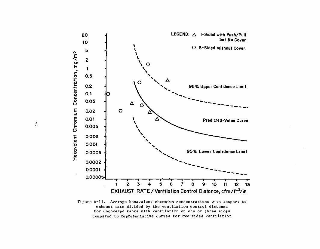
.I"-\.ft
20 LEGEND: l:::.. I-Sided with Push/PUll
10 but No Cover.
\ o 3-Sided without Cover. 5 \
10 \ E \ "- 2 \ C' \ 0 E 1 , - ,
c 0.5
, 0 , ..... .... l:::.. 0 .... ... 0.2 , 95% Upper Confidence Limit. ..... ' .... c Q) 0.1 ... u ...... c -... 0 0.05 --u l:::.. --- -- .... -- - .... _---E 0.02 0 =-E 0.01 \ Predicted-Value Curve 0 \ ...
0.005 \ .r. U \ ..... 0.002
, c , Q)
, 0 0.001 .... .... > , 0
0.0005 , 95% Lower Confidence Limit x ...
Q) ... :r: ......
0.0002 -- ... --0.0001 -------0.00005
1 2 3 4 5 6 7 8 9 10 11 12 13
EXHAUST RATE /Ventilation Control Distance, cfm/ft~/in.
Figure 6-11. Average hexavalent chromium concentrations with respect to exhaust rate divided by the ventilation control distance
for uncovered tanks with ventilation on one or three sides compared to representative curves for two-sided ventilation
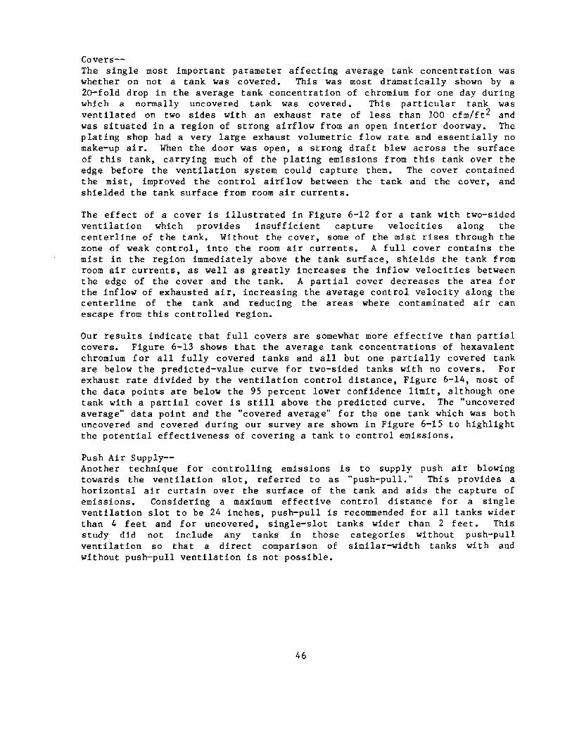
Covers--The single most important parameter affecting average tank concentration was whether on not a tank was covered. This was most dramatically shown by a 20-fold drop in the average tank concentration of chromium for one day during which a normally uncovered tank was covered. This particular tank was ventilated on two sides with an exhaust rate of less than 100 dm/ft2 and was situated in a region of strong airflow from an open interior doorway. The plating shop had a very large exhaust volumetric flow rate and essentially no make-up air. When the door was open, a strong draft blew across the surface of this tank, carrying much of the plating emissions from this tank over the edge before the ventilation system could capture them. The cover contained the mist, improved the control airflow between the tank and the cover, and shielded the tank surface from room air currents.
The effect of a cover is illustrated in Figure 6-12 for a tank with two-sided ventilation which provides insufficient capture velocities along the centerline of the tank. Without the cover, some of the mist rises through the zone of weak control, into the room air currents. A full cover contains the mist in the region immediately above the tank surface, shields the tank from room air currents, as well as greatly increases the inflow velocities between the edge of the cover and the tank. A partial cover decreases the area for the inflow of exhausted air, increasing the average control velocity along the centerline of the tank and reducing the areas where contaminated air can escape from this controlled region.
Our results indicate that full covers are somewhat more effective than partial covers. Figure 6-13 shows that the average tank concentrations of hexavalent chromium for all fully covered tanks and all but one partially covered tank are below the predicted-value curve for two-sided tanks with no covers. For exhaust rate divided by the ventilation control distance, Figure 6-14, most of the data points are below the 95 percent lower confidence limit, although one tank with a partial cover is still above the predicted curve. The "uncovered average" data point and the "covered average" for the one tank which was both uncovered and covered during our survey are shown in Figure 6-15 to highlight the potential effectiveness of covering a tank to control emissions.
Push Air Supply--Another technique for controlling emissions is to supply push air blowing towards the ventilation slot, referred to as "push-pull." This provides a horizontal air curtain over the surface of the tank and aids the capture of emissions. Considering a maximum effective control distance for a single ventilation slot to be 24 inches, push-pull is recommended for all tanks wider than 4 feet and for uncovered, single-slot tanks wider than 2 feet. This study did not include any tanks in those categories without push-pull ventilation so that a direct comparison of similar-width tanks with and without push-pull ventilation is not possible.
46

\
NO COVER
FULL COVER
I .. • ::I
:= ~
PARTIAL COVER
Figure 6-12. Effect of full and partial covers on controlled airflow for a tank with two-sided ventilation.
47
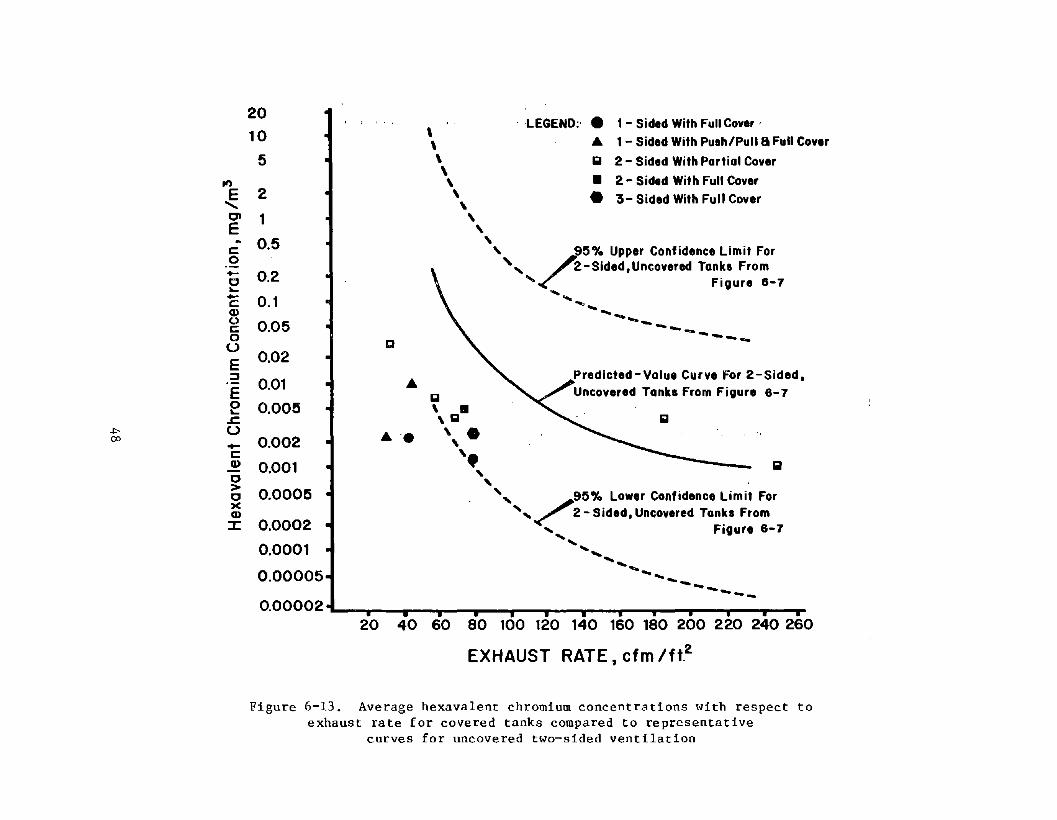
.., E
....... CI E c 0 +-c ... .... c Q) 0 c 0 u E :::J
E 0 ... ~
~ U co -c Q)
c > c )( Q)
::z:
20
10
5
2
1
0.5
0.2
0.1
0.05
0.02
0.Q1
0.005
0.002
0.001
0.0005
0.0002
0.0001
0.00005
0.00002
A-.
\ \ \ \ \
\
iii
\ \
, . ,iii
, ,
\ . , " ... ...
LEGEND:' • 1 - Sided With Full Cover,
A 1 - Sided With Push/Pull a Full Cover
iii 2 - Sided With Partial Cover
• 2 - Sided With Full Cover
• 3- Sided With Full Cover
, r95"10 Upper Confidence Limit For " 2-Slded.Uncovered Tonka From
..... Figure 8-7 .... ....
'"' .... ... ------ ..... --..---
Predicted-Value Curve For 2-Sided. Uncovered Tanks From Figure 8-7
"', /,95% Lower Confidence Limit For "< 2-Sided, Uncovered Tanka From
, Figure 6-7 ........ ....... ....... ........ ....... ------
20 40 60 80 100 120 140 160 180 200 220 240 260
EXHAUST RATE, efm Itt2
Figure 6-13. Average hexavalent chromium concentrations with respect to exhaust rate for covered tanks compared to representative
curves for uncovered two-sided ventilation

"'" \D
20
10 \
5 \ If) \ E \
" 2 \ CI \ E 1 , ~ ,
c: 0 +-0 ~
+-c: Q) u c: 0 U
E ::J
E 0 ~
~
U +-c: Q)
0 > 0 x Q)
:J:
0.5 , " , " 0.2 '....... /95% Upper Confidence Limit.
0.1 " ........ 0.05 -------12 ~---- --0.02
0.01 ... \ Predicted-Value Curve G
0.005 \ . , g g
0.002 ~ • , , , 0.001 • , iii , , 0.0005 ' ......... /95% lower Confidence limit
0.0002 ..... ------0.0001 ------1 2 3 4 5 6 7 e 9 10 11 12 13
EXHAUST RATE I Ventilation Control Distance, cfm/ft2/in.
Figure 6-14. Average hexavalent chromium concentrations with respect to exhaust rate divided by the ventilation control distance for covered tanks with ventilation on one or three sides compared to representative curves for uncovered two-sided ventilation

\J1 0
2
., E "-'" 0.5 E C 0 0.2
""6 ... 0.1 C .,
u c 0.05 0
u E 0.02 .:! E e 0.01
.c:. U 0.005 C ~ <1 0.002 > <1 >( .,
0.001 :I:
0.0005
D
OSHA PEL (CEILING LIMIT)
-----------------~-----------------. ~NIOSH RECOMMENDED CEILING LIMIT FOR
NON-CARCINOGENIC HEXAVALENT CHROMIUM
•
._._._._._._-"'""['"""._._._-_._._.-
20 40 60
~ NIOSH RECOMMENDED CEILING LIMIT FOR CARCINOGENIC HEXAVALENT CHROMIUM
80 100 120 140 160 180 200 220 240 260
EXHAUST RATE. cfm/flz
Figure 6-15. Average hexavalent chromium concentrations with respect to exhaust rate for one tank with and without a cover
compared to pertinent ceiling limits.
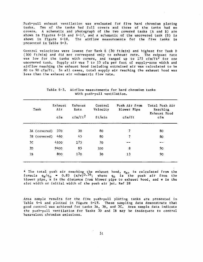
Push-pull exhaust ventilation was evaluated for five hard chromium plating tanks. Two of the tanks had full covers and three of the tanks had no covers. A schematic and photograph of the two covered tanks (A and B) are shown in Figures 6-16 and 6-17, and a schematic of the uncovered tank (D) is shown in Figure 6-18. The airflow measurements for the five tanks is presented in Table 6-3.
Control velocities were lowest for Tank E (30 ft/min) and highest for Tank D (100 ft/min) and did not correspond only to exhaust rate. The exhaust rate was low for the tanks with covers, and ranged up to 175 cfm/ft2 for one uncovered tank. Supply air was 7 to 13 cfm per foot of supply-zone width and airflow reaching the exhaust hood including entrained air was calculated to be 80 to 90 cfm/ft. In all cases, total supply air reaching the exhaust hood was less than the exhaust air volumetric flow rate.
Table 6-3. Airflow measurements for hard chromium tanks with push-pull ventilation.
Exhaust Exhaust Control Push Air from Total Push Air Tank Air Rate Velocity Blower Pipe Reaching
Exhaust Hood cfm cfm/ft2 ft/min cfm/ft cfm
3A ( covered) 370 30 80 7 80
3B (covered) 460 45 80 7 80
3C 4100 175 70
3D 9400 85 100 8 90
lB 800 170 30 13 90
* The total push air reaching the exhaust hood, qx' is calculated from the formula qx/qo = 0.83 (x/w)0.36; where qo is the push air from the blower pipe, x is the distance from blower pipe to exhaust hood, and w is the slot width or initial width of the push air jet. Ref 28
Area sample results for the five push-pull plating tanks are presented in Table 6-4 and plotted in Figure 6-19. These sampling data demonstrate that good control was achieved for tanks 3A, 3B, and 3C. Area sample data indicate the push-pull ventilation for Tanks 3D and lB may be inadequate to control hexavalent chromium emissions.
51
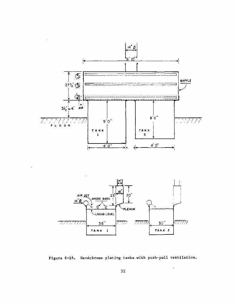
I ! I
I~
I /l i /
FL.OOR
9'0"
TANK
1
~I 19' 10J 1 r
TA N K
2
1 8
1
0"
j 'JII///
4' 0" I 4' 0" I+-~ -----.:~---+~ < ~ ... ~ --.::.......:::...---~ I
1 AIR JET 23
14"rz) O\ANOOE BARS ! I --O\l Ai o.
M I~
- ~
\'L.IQUIO LEVEL
/////// 30" , I ,'// / :' l~'.':j / J .' .'.' 36' I 7""'!77 I+-----==--=---~~I
TA N K TA N K 2
Figure 6-16. Hardchrome plating tanks with push-pull ventilation.
52

Figure 6-17. Tanks A and B with covers and push-pull ventilation.
Figure 6-18. Schematic of tank with push-pull ventilation.
53
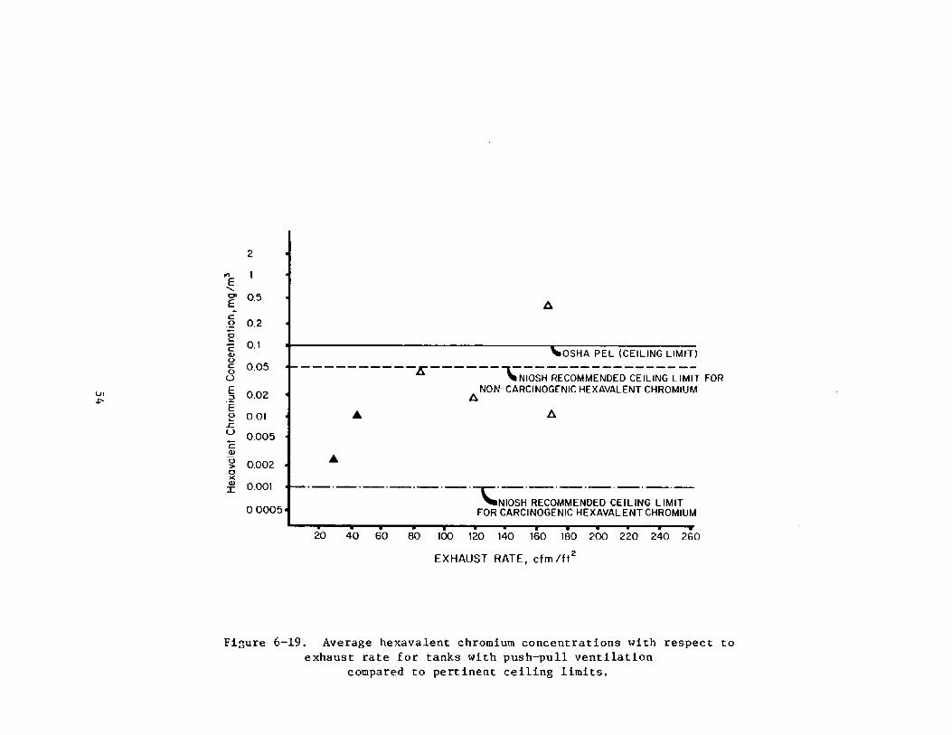
I..n .p-
2
... E "-
'" 0.5 E -c: .9 0.2
~ 0.1 C .,
u c: 0.05 0 u E 0.02 .:::! E e 0.01 L. u 0.005 C ., 0 0.002 > 0 )( .,
0.001 I
00005
OSHA PEL (CEILING LlM1TJ
----------E------~-----------------"NIOSH RECOMMENDED CEILING LIMIT FOR
A NON-CARCINOGENIC HEXAVALENT CHROMIUM
'-'-----'-----r-----'-----'-'-'NIOSH RECOMMENDED CEILING LIMIT
FOR CARCINOGENIC HEXAVALENT CHROMIUM
20 40 60 BO 100 120 140 160 180 200 220 240 260
EXHAUST RATE, cfm /ft2
Fi3ure 6-19. Average hexavalent chromium concentrations with respect to exhaust rate for tanks with push-pull ventilation
compared to pertinent ceiling limits.

Table 6-4. Average concentrations around tanks with push-pull ventilation.
Tank No.
3A
3B
3C
3D
lB
No. of Samples
6
6
6
11
10
Hexavalent Chromium Concentration Cmg/m3)
0.002
0.010
0.011
0.043
0.360
Control of hexavalent chromium from tanks 3A and 3B can be attributed to full covers in conjunction with push-pull ventilation at very low exhaust rates of less than 50 cfm/ft2. Personal samples taken on the worker at tanks 3A and 3B demonstrate a very good level of control. Three personal samples for one worker averaged 0.002 mg/m 3 , less than l/lOth the NIOSH recommended time-weighted average standard for hexavalent chromium of 0.025 mg/m 3 •
Effective control of tank 3C was due to push-pull ventilation with a much higher exhaust rate of 175 cfm/ft2. The use of plastic balls may help reduce emissions for this tank, but the extent of this reduction is not known. Three personal samples taken on the worker at Tank 3C averaged 0.007 mg/m3 , which also represents good control of hexavalent chromium exposures.
Based on personal exposure data, the controls of tank 3D was adequate, but the volumetric flow rates for both the push and the exhaust systems was insufficient. The 85 cfm/ft2 exhaust rate is less than the minimum value of 100 cfm/ft 2 recommended in the Industrial Ventilation Manual, and the push air supply provides less than 20 percent of the recommended design value. These deficiencies may be noticeable in some of the area sam~les. Although the average tank-area concentration was less than 0.05 mg/m , some of the individual samples for hexavalent chromium measured concentrations around 0.2 mg/m 3 , about twice the OSHA permissible exposure (ceiling) limit for personal exposures. However~ two personal samples taken on the worker at Tank 3D averaged only 0.003 mg/m. Thus, despite fairly high hexavalent chromium concentrations around the tank, the worker--who spent most of the day within four feet of the tank but very little time directly over it--was not overexposed.
The push ventilation on tank lB was inadequate to control hexavalent chromium emissions. The exhaust rate of 170 cfm/ft2 exceeds the recommended design value range of 100 to 150 cfm/ft 2 , but the supply air value is only 25 percent to 40 percent of the amount required for the recommended value range and less than 15 percent of that necessary to match the observed exhaust rate. Another major problem appears to be the direction of the supply air jet
55

along with the low control velocity at the edge of the tank. Chromic acid mist, picked up by the supply air jet, is blown toward the anode bars and bounces back into the area above the tank between the push-air pipe and top edge of the tank. This area would coincide with the breathing zone of a worker operating the tank. Personal samples were not taken for this tank because it was not in production; area samples were collected while dummy loads were plated.
Area sample data show that sulfuric acid emissions were satisfactorily controlled using push-pull ventilation. The highest sulfuric acid concentration for the five tanks was 0.8 mg/m 3 • The sulfuric acid data presented no significant trends and appeared to be independent of hexavalent chromium levels. Personal samples for sulfuric acid taken on three workers at Tanks 3A, 3B, 3C, and 3D were all less than 0.2 mg/m 3 .
General Ventilation--Area samples for hexavalent chromium were taken in five of the plating shops. The samplers were placed away from the immediate Vicinity of the chromium plating tanks to measure the overall or background concentrations in the plant. Table 6-5 summarizes some of the data about the plants along with the average hexavalent chromium background concentration and the average concentration for all the sampled chromium plating tanks in each shop. These plants were either job or production shops devoted to hard chromium plating only.
Table 6-5. Selected plant data and average tank-area concentrations for hexavalent chromium compared to average general air concentrations.
Mechanical General Average* Average Plant Doors/ Hake-up Exhaust Chromium Tank General Air
Plant Volume Windows Air Ventilation Concentration Concentration
cu/ft in each ~lant
mg/m mg/m 3
2 30,000 Closed None None 0.200 0.017 (4)**
8 30,000 Open None None 0.180 0.002 (8)
4 60,000 Mostly Yes None 0.020 0.002 (6)
closed 5 150,000 Open None None 0.012 0.002 (9)
6 140,000 Mostly None Yes 0.008 0.001 ( 9)
open
* arithmetic mean
** Shown in parenthesis are the number of general air samples taken.
56

In four of the five shops, the background hexavalent chromium concentrations were very low--from 0.001 to 0.002 mg/m 3 . These low levels indicated either: (1) good source control of chromium plating emissions at the tank; or (2) an effective general ventilation system. All of the plants had relatively heavy plating workloads. The general background air concentrations ranged from 1 percent to 18 percent of the average tank concentrations for hexavalent chromium.
The highest average background level of hexavalent chromium (0.017 mg/m 3) was found at plant 2. This is on the order of ten times higher than those in the other hard chromium plating shops. There appear to be several reasons for the higher background levels in plant 2. The primary cause is insufficient make-up air because of closed doors and windows with no provisions for mechanically supplied make-up air.
Plants 2 and 8 are the same hard chromium plating shop but represent surveys taken at different times during the year. The first survey (plant 2) was conducted during the winter with doors and windows closed. There was a strong negative pressure inside the plating shop. The autumn survey (plant 8) was conducted during mild weather with doors and windows open. This allowed sufficient make-up air to flow into the plant. The average hexavalent chromium concentrations measured at the plating tanks were essentially the same for both surveys--0.20 mg/m 3 in the winter and 0.18 mg/m 3 in the autumn. Thus, the general ventilation, not local exhaust ventilation at the plant tanks, appears to be the cause for the tenfold differences in background hexavalent chromium levels between surveys 2 and 8. (Note that local exhaust ventilation rates measured during both surveys were the same.)
Both the general area concentrations as well as the chromium tank concentrations were quite low in plant 4, averaging 0.002 and 0.020 mg/m 3
respectively. The survey at plant 4 was conducted in the spring in cool weathe"r with the doors and windows mostly closed. Make-up air was supplied to the shop at a rate of 14,000 cfm, while total exhaust volume (calculated by summing the individual tank ventilation rates) was 13,400 cfm. These numbers indicate a well balanced ventilation system in the shop. These calculations are consistent with observed conditions during the survey, because neither a negative nor positive pressure was apparent in the building. The proper supply of make-up air contributed to lower concentrations in the shop, because the infusion of make-up air allows the local exhaust ventilation to work at maximum efficiency. The additional make-up air also provides some dilution ventilation, further reducing the airborne concentration of hexavalent chromium, and of other contaminants which are not captured by the local exhaust ventilation.
The survey at plant 5 was conducted in the summer with doors and windows open. There was no general exhaust ventilation or mechanical make-up air supply. The hexavalent chromium levels at the chromium tanks and in the general room air were low, averaging 0.012 and 0.002 mg/m 3 respectively.
The plant 6 survey was conducted in the late summer. equipped with a roof ventilation fan that was measured This roof fan provided three to four air exchanges per
57
The plating shop was to exhaust 13,000 cfm. hour in the production
area. There was no mechanical make-up air supply. In the 3-day survey, the roof exhaust fan was on except during the morning of the third day. Make-up air was supplied through open doors on the first and second days of the survey. On the third day, doors were closed in the morning (cool weather) and opened in the afternoon. General area samples for hexavalent chromium averaged two to three times higher on the third day than on the previous two days (in spite of a lower production rate on the third day), apparently due to the shutdown of the roof fan and closing of the doors during that morning. This limited data substantiates the importance of sufficient make-up air and general ventilation along with adequate local exhaust ventilation.
Reverse Chromium Stripping
A reverse chromium strip tank, 3-feet by 7-feet by 4-feet-deep, equipped with two-sided exhaust ventilation, was assessed. The exhaust slots are along the 7-foot dimension and are l-l!2-inches-wide. Emissions are exhausted through expanding-type plenums on the sides of the tank to a single plenum at the end of the tank. There were no covers on the tank, nor were floating plastic balls used. The chromium strip bath contained 33 oz/gal chromic acid and was at room temperature. The tank was operated at 6 volts and 800 to 1,000 amps. Aluminum cylinder blocks requiring rework are placed in the bath. Current is applied so that the block is the anode, which is the reverse of chrome plating (the cathode is a piece of iron). The blocks are stripped of all chromium down to the aluminum surface.
The tank was observed in operation for two hours, during which a 6-cylinder engine block was hung in the center of the tank and stripped. Two area air samples were taken during this operation; one sample was located on top of a ventilation slot, the other was located on an unventilated side of the tank.
Total exhaust volume and exhaust rate for this tank were 1,160 cfm and 56 cfm/ft 2 , respectively. This exhaust rate was around 33 percent of the ACGIH 7 recommended value of 175 cfm/ft2. Slot velocities were very uniform on both sides of the tank, and ranged from 700 to 900 feet per minute.
The two area samples taken showed Chromium VI levels of 0.004 mg/m3
(directly above a ventilation slot) and less than 0.001 mg/m3 (on an unventilated side). Both samples are well below the NIOSH recommended level of 0.025 mg/m3 for Chromium VI (noncarcinogenic) and the OSHA PEL of 0.100 mg/m3 • This very limited data indicates good control of chromic acid mists from chrome stripping operations at an exhaust rate of only 60 cfm/ft 2 using two-sided local exhaust ventilation for a 3-foot-wide tank. Average breathing zone levels for this tank should be even less than those measured, since some dilution due to normal workplace air turbulence would be expected.
Silver Plating
Four silver electroplating tanks (consisting of two silver strike tanks and two silver plating tanks) were evaluated. These tanks were located in two plants. The tank parameters, bath concentrations, temperature, and ventilation measurements are presented in Table 6-6.
58
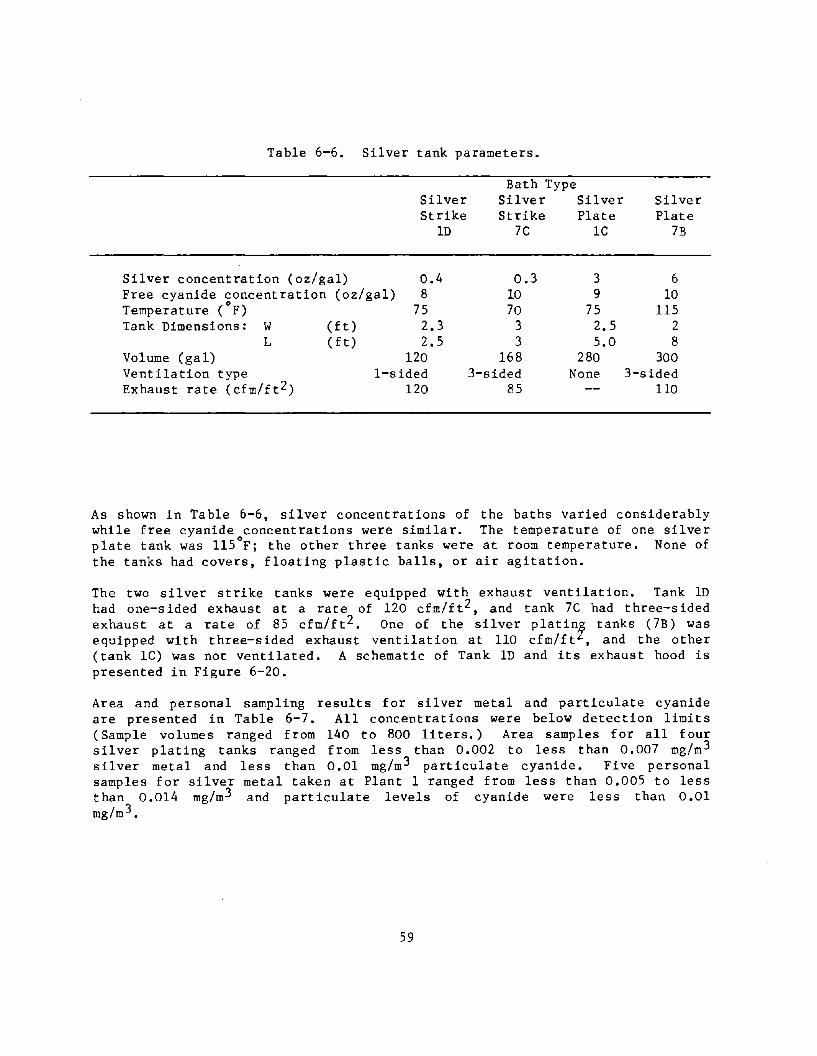
Table 6-6. Silver tank parameters.
Silver concentration (oz/gal)
Silver Strike
lD
0.4 Free cyanide concentration (oz/gal) 8 Temperature (oF) 75 Tank Dimensions: W (ft) 2.3
L (ft) 2.5 Volume (gal) 120 Ventilation type I-sided Exhaust rate (cfm/ft2) 120
Bath Type Silver Silver Strike Plate
7C lC
0.3 3 10 9 70 75
3 2.5 3 5.0
168 280 3-sided None
85
Silver Plate
7B
6 10
115 2 8
300 3-sided
110
As shown in Table 6-6, silver concentrations of the baths varied considerably while free cyanide concentrations were similar. The temperature of one silver
° plate tank was 115 F; the other three tanks were at room temperature. None of the tanks had covers, floating plastic balls, or air agitation.
The two silver strike tanks were equipped with exhaust ventilation. Tank lD had one-sided exhaust at a rate of 120 cfm/ft2, and tank 7C had three-sided exhaust at a rate of 85 cfm/ft2. One of the silver platin:r tanks (7B) was equipped with three-sided exhaust ventilation at 110 cfm/ft , and the other (tank lC) was not ventilated. A schematic of Tank lD and its exhaust hood is presented in Figure 6-20.
Area and personal sampling results for silver metal and particulate cyanide are presented in Table 6-7. All concentrations were below detection limits (Sample volumes ranged from 140 to 800 liters.) Area samples for all four silver plating tanks ranged from less than 0.002 to less than 0.007 mg/m3
s il ver metal and less than 0.01 mg/m 3 particulate cyanide. Five personal samples for silver metal taken at Plant 1 ranged from less than 0.005 to less than 0.014 mg/m3 and particulate levels of cyanide were less than 0.01 mg/m 3•
59

Table. 6-7. Air sampling results - silver plating (mg/m 3).
Silver Particulate C~anide Geom. No. Geom. No.
Tank/Worker Mean Range Samples Hean Range Samples
Area Sample Silver strike 10 <0.006 <0.005 to 8 <0.01 8
<0.007 Silver plate lC <0.006 <0.004 to 10 <0.01 10
<0.008 Silver plate 7B <0.005 <0.003 to 4 <0.002 <0.001 to 2
<0.007 <0.004 Silver strike 7C <0.003 <0.002 to 4 <0.001 2
<0.003 Personal Samples
Plater I-II <0.007 <0.005 5 <0.01 5 <0.014
Plater 7-1 <0.002 3
OSHA PEL 0.01 5.0 N10SH Recommended 5.0 (10 min. ceiling)
60

9"
+ ~------------------~~
6"
~----------------~~ 7"
I 1+(--- 30"
I 33 ';~'
\
'-----~L 1 ..... <----28"--~1
Figure 6-20. Silver plating tank ID.
61

The results show that no emissions from either ventilated or nonventilated silver tanks were detected. Although no airborne silver was detected in this study, it is important to note that the OSHA standard for silver is very low (0.01 mg/m3 ). Particulate cyanide levels were all less than 0.01 mg/m3 which is less than 0.2 percent of the OSHA 8-hour permissible exposure.
Because all the samples were below detection limits, comparisons between silver strike and silver plate tanks and between ventilated and nonventilated tanks cannot be made. The data for silver plate tank lC does indicate ventilation may not be needed at all for silver plating tanks and possibly for silver strike tanks during normal operating conditions However, the use of ventilation is prudent for all silver cyanide tanks as a precaution because the tanks do contain cyanide which may be liberated through the inadvertent addition of a reactive chemical such as an acid (causing the release of hydrogen cyanide).
Copper Plating
Three copper plating tanks located at two separate facilities were evaluated. Tank, bath parameters, and ventilation for these tanks are presented in Table 6-8. All three tanks contain copper strike baths with approximately the same copper and cyanide concentrations and pH. The major difference is the size of the tanks (Tank IF was approximately 5 to 6 times larger than the others).
Table 6-8. Copper plating tank parameters.
Copper concentration Free cyanide concentration Bath temperature ( oF)
pH Tank dimensions: width (ft)
lengt h( ft) Tank volume (gal) Type ventilation Exhaust rate (cfm/ft2) Recommended exhaust rate (cfm/ft 2)", Control velocity
'" Industrial Ventilation7
Copper Strike
IE
3 1.5
110 13.1
2.5 2.2
125 I-sided
52 150
10
Bath Type Copper Strike
IF
3 1.5
110 13
3.7 9
760 I-sided
144 110
50
Copper Strike
7F
5 2.0
130 12.5
3 3
168 3-sided
158 130
Two of the copper plating tanks were equipped with one-sided local exhaust ventilation, and the third with three-sided local exhaust ventilation. Air was exhausted across a distance of 2.5 feet for tank IE, 3.7 feet for tank IF,
62

and only 1.2 feet for tank 7F (because three sides of the tank were ventilated, the maximum draw is across half the tank width of 2.3 ft). Exhaust rates for the three strike baths ranged from 52 to 158 cfm/ft2. Tank IF (including the ventilation hood) is shown on Figure 6-21. None of the tanks employed floating plastic balls, mist suppressants, nor had covers.
Area samples for copper dust (or mist) and particulate cyanide were collected for the three tanks, and these results are presented in Table 6-9. As seen, all area sample concentrations were below the detection limit for both copper and cyanide. Thus, all the samples were less than one percent of the 1 mg/m3 OSHA PEL for copper dust (and mists) and less than 0.2 percent of 5 mg/m 3 , the OSHA PEL for cyanide (NIOSH recommends a maximum of 5.0 mg/m3 for cyanide for 10 minutes). Personal samples were taken at Plant I, and all but one of eleven samples were below the detection limit for copper. The one detection concentration was 0.12 mg/m 3 • The personal samples for cyanide were also below the detection limit.
Table 6-9. Air sampling results - copper plating.
Tank/Worker
Area Sample Copper strike IE Copper strike IF Copper strike 7F
Personal Samples
Plater 1-11 Plater l-II2
OSHA PEL NIOSH Recommended
Copper Geom. No. Mean. Range Samples
mg/m3 mg/m 3
<0.01 <0.01 <0.003
<0.01 0.02
1.0
<0.01 0.12
to
10 17
3
.5 6
1. Plater A's duties included Tank 1E 2. Plater B's duties included Tank IF
63
Particulate Cyanide Geom. No. Mean Range Samples
mg/m 3 mg/m3
<0.01 <0.01
<0.01 <0.01
5.0 5.0 10 min.
10 17
5 6
ceiling)
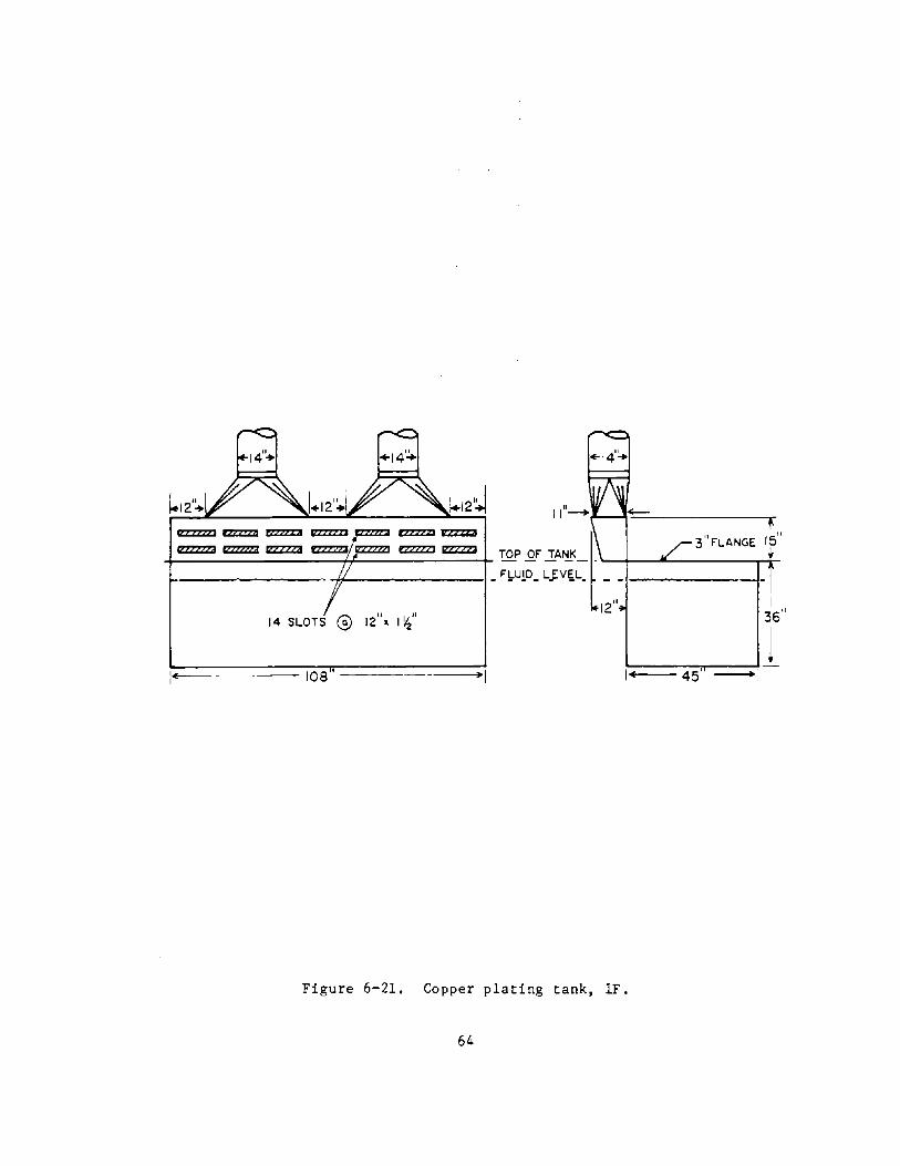
1-- 108 , 1
I
36"
[1+, ===445"5 '~:::::;i. I 1
Figure 6-21. Copper plating tank, IF.
64
The results, consisting of 30 area samples (27 for cyanIde) and 11 personal samples, show copper dust and particulate cyanide levels were extremely low for the copper cyanide strike bath. Ventilation data presented in Table 6-8 show the exhaust rate for tank IE was one-third the recommended rate, but the exhaust rates for tank IF and 7F exceeded the recommended exhaust rate. 6 It should be noted that tanks IE and IF are Rochelle copper cyanide baths with a cathode efficiency of 40 to 50 percent. 3 ,70 Some copper strike baths use plain cyanide solutions with cathode efficiencies of 25 to 30 percent and therefore may require a little higher exhaust ventilation rate than the Rochelle baths.
The results also show that a ventilation rate of 144 cfm/ft2 was very effective in controlling particulate cyanide across a tank almost 4-feet-wide. Adding local exhaust ventilation to copper strike tanks is a precautionary measure in case acid comes in contact with the bath and hydrogen cyanide (HCN) is released. The acidic action of carbon dioxide in the air at the surface of the bath could possibly cause the release of HCN gas. 7
Nickel Plating
NIOSH has recommended that the permissible exposure for nickel be reduced to 0.015 mg/m 3 and that nickel be treated as an occ,-,pational carcinogen. 16
Five nickel electroplating baths at four facilities were evaluated; theb-ath concentrations, operating conditions, and local exhaust ventilation data for each nickel tank are presented in Table 6-10. Three of the tanks (lG, lH, and 2F) contained Watts nickel bath and two tanks (7G and 9D) contained nickel sulfamate. Nickel metal and boric acid concentrations were approximately the same in all five baths. The bath temperature for tank 2F (160°F) was considerably higher than for the other tanks. The tanks ranged in size from 370 to 1,680 gallons. Only one tank was equipped with local exhaust ventilation and it was not working during the survey because of a closed damper. None of the tanks were covered, contained floating plastic balls, or were air agitated; however, four tanks were mechanically agitated by: barrel rotation in tanks lG and lH, a stirrer on tank 7G, and a horizontal reciprocator on tank 9D.
65
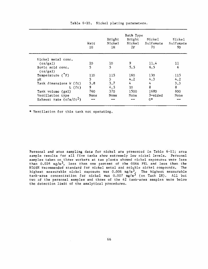
Table 6-10. Nickel plating parameters.
Bath Type Bright Bright Nickel Nickel
Watt Nickel Nickel Sulfamate Sulfamate lG lH 2F 7G 9n
Nickel metal conc. (oz/gal) 10 10 9 11.4 II
Boric acid conc. 5 5 5.5 6.5 6 (oz/ gal)
Temperature (oF) llO ll5 160 130 ll5 pH 5 5 4.2 4.3 4.2 Tank dimensions W (ft) 3.8 3.7 4 4 3.3
L (ft) 9 4.5 10 8 8 Tank volume (gal) 760 370 1500 1680 800 Ventilation type None None None 3-sided None Exhaust rate (cfm/ft2) 0*
* Ventilation for this tank not operating.
Personal and area sampling data for nickel are presented in Table 6-11; area sample results for all five tanks show extremely low nickel levels. Personal samples taken on three workers at two plants showed nickel exposures were less than 0.016 mg/m3 , less than one percent of the OSHA PEL and less than the NIOSH recommended standard for nickel metal and soluble nickel compounds. The highest measurable nickel exposure was 0.006 mg/m3 . The highest measurable tank-area concentration for nickel was 0.007 mg/m3 (on Tank lH). All but two of the personal samples and three of the 42 tank-area samples were below the detection limit of the analytical procedures.
66
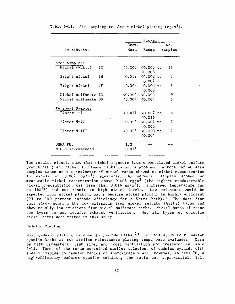
Table 6-11. Air sampling results - nickel plating (mg/m 3).
Nickel Geom. No.
Tank/Worker Mean Range Samples
Area Samples: Nickel (Watts) lG <0.006 <0.005 to 16
<0.008 Bright nickel lH 0.002 <0.002 to 3
0.007 Bright nickel 2F 0.003 0.002 to 6
0.003 :-ackel sulfamate 7G <0.004 <0.004 9 Nickel sulfamate 9D <0.004 <0.004 6
Personal Samples: Plater I-I <0.011 <0.007 to 6
<0.016 Plater 9-II 0.004 <0.004 to 2
0.006 Plater 9-III <0.003 <0.003 to 2
<0.004
OSHA PEL 1.0 NIOSH Recommended 0.015
The results clearly show that nickel exposure from unventilated nickel sulfate (Watts bath) and nickel sulfamate tanks is not a problem. A total of 40 area samples taken on the perimeter of nickel tanks showed no nickel concentration in excess of 0.007 mg/m 3 ; similarly, 10 personal samples showed no measurable nickel concentration above 0.006 mg/m 3 (the highest nondetectable nickel concentration was less than 0.016 mg/m 3 ). Increased temperature (up to l60°F) did not result in high nickel levels. Low emissions would be expected from nickel plating baths because nickel plating is highly efficient (95 to 100 percent cathode efficiency for a Watts bath).3 The data from this study confirm the low emissions from nickel sulfate (Watts) baths and show equally low emissions from nickel sulfamate baths. Nickel baths of these two types do not require exhaust ventilation. Not all types of chloride nickel baths were tested in this study.
Cadmium Plating
Most cadmium plating is done in cyanide baths. 70 In this study four cadmium cyanide baths at two airline maintenance plating shops were evaluated. Data on bath parameters, tank size, and local ventilation are presented in Table 6-12. Three of the tanks contained similar solutions of cadmium cyanide with sodium cyanide to cadmium ratios of approximately 4:1, however, in tank 7E, a high-efficiency cadmium cyanide solution, the ratio was approximately 2:1.
67

Tanks 7D and 9B also contained brighteners (organic or metallic compounds that add luster or shine to the plated part). All four tanks were at room temperature, and none of the tanks were covered or employed either floating plastic balls or mist suppressants. A cadmium tank is shown in Figure 6-22.
Table 6-12. Cadmium plating parameters
Bath Type
Cadmium metal conc. (oz/gal) Cyanide conc. as NaCN (oz/gal)
0
Temperature F pH Tank dimensions W (ft)
L (ft) Tank volume (gal) Ventilation type Exhaust rate (cfm/ft2)
Bright Cadmium Cyanide
7D
3.0 13 70 13.2 5 8 2100 None
Hi-Efficiency Cadmium Cyanide
7E
7.2 13 70 13.7 5 10 3740 3-sided 58
Bright Cadmium Cyanide
9B
4 15 75
2.5 7.7 570 2-sided 136
Figure 6-22. Cadmium plating tank - ventilated.
68
Dull Cadmium Cyanide
9C
4 15 75
2.5 5.7 640 2-sided 155
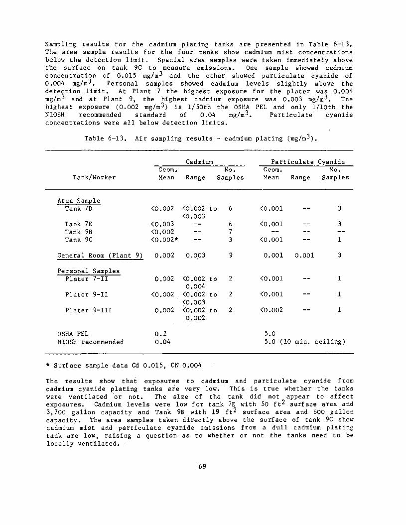
Sampling results for the cadmium plating tanks are presented in Table 6-13. The area sample results for the four tanks show cadmium mist concentrations below the detection limit. Special area samples were taken immediately above the surface on tank 9C to measure emissions. One sample showed cadmium concentration of 0.015 mg/m 3 and the other showed particulate cyanide of 0.004 mg/m3 • Personal samples showed cadmium levels slightly above the detection limit. At Plant 7 the highest exposure for the plater was 0.004 mg/m 3 and at Plant 9, the highest cadmium exposure was 0.003 mg/m 3 • The highest exposure (0.002 mg/m 3 ) is 1/50th the OSHA PEL and only l/lOth the ~IOSH recommended standard of 0.04 mg/m 3 • Pa rt iculate cyanide concentrations were all below detection limits.
Table 6-13. Air sampling results - cadmium plating (mg/m 3).
Cadmium Particulate Cyanide Geom. No. Geom. No.
Tank/Worker Mean Range Samples :1ean Range Samples
Area Sample Tank 7D <0.002 <0.002 to 6 <0.001 3
<0.003 Tank 7E <0.003 6 <0.001 3 Tank 9B <0.002 7 Tank 9C <0.002* 3 <0.001 1
General Room (Plant 9) 0.002 0.003 9 0.001 0.001 3
Personal Samples Plater 7-II 0.002 <0.002 to 2 <0.001 1
0.004 Plater 9-II <0.002 <0.002 to 2 <0.001 1
<0.003 Plater 9-III 0.002 <0·.002 to 2 <0.002 1
0.002
OSHA PEL 0.2 5.0 NIOSH recommended 0.04 5.0 (10 min. ceiling)
* Surface sample data Cd 0.015, CN 0.004
The results show that exposur~s to cadmium and particulate cyanide from cadmium cyanide plating tanks are very low. This is true whether the tanks were ventilated ·or not. The size of the tank did not appear to affect exposures. Cadmium levels were low for tank 7E with 50 ft 2 surface area and 3,700 gallon capacity and Tank 9B with 19 ft 2 surface area and 600 gallon capacity. The area samples taken directly above the surface of tank 9C show cadmium mist and particulate cyanide emissions from a dull cadmium plating tank are low, raising a question as to whether or not the tanks need to be locally ventilated.
69

It aprears the cadmium cyanide plating tanks do not require ventilation under ~orma operating conditions; however, cyanide solutions can be very hazardous ~n the presence of acids. If a rinse tank with even small amounts of acid precedes a cadmium cyanide tank, then the cadmium tank may need to be ventilated. 3
Zinc Plating
A low cyanide zinc plating tank in an automatic rack line was evaluated. The automatic rack line shown in Figure 6-23 consists of a series of soak and electrolytic cleaners, acid pickle, de-smut, zinc plating bright dip, and dichromate tanks. Parts are hung by the workers at the open end of the horseshoe-shaped plating line. The line is completely automated; other than the occasional addition of chemicals to the tanks no one needs to work directly over or next to the tanks. Workers take the pieces off the racks at the end of the line. Although the zinc plating line is essentially automatic, the potential release of plating mists and fumes into the general work area was a concern.
The zinc plating tank contains a low cyanide zinc plating solution consisting of 1 to 1.5 oz/gal zinc metal, 10 to 12 oz/gal sodium hydroxide, and 3 oz/gal or less total cyanide at a bath temperature of 85°F. The tank, shown schematically in Figure 6-24, is approximately 50-feet-long, 5.3-feet wide, and 5-feet deep, and holds 9,450 gallons of solution. In the plating operations the automatic rack machine lowers the racks into the solution at one end, moves the rack through the solution to the other end (slot hood end), and raises the rack out of the tank. Air agitation is not used in the tank.
The zinc plating tank was ventilated with a canopy exhaust hood and a slot exhaust hood shown in Figure 6-24. The canopy hood was 20-feet by 4-feet, and was located over the middle portion of the tank. The average face velocity was 60 fpm and the total exhaust airflow of the canopy hood was calculated from the face velocity to be 4,800 cfm. The canopy hood is approximately 30-inches above the tank. Measurements 20-inches below the hood (IO-inches above the tank) show capture velocities averaging about 20 fpm, indicating the canopy hood acts only as a recovery hood capturing mists and fumes that rise vertically into the hood.
The zinc tank is also equipped with a slot exhaust hood 9.5-feet-wide by 4-feet-high with a l-foot-deep plenum. The hood has 16 slots, each 3-inches by 24-inches, and draws across the 5.3-foot-width of the tank. Capture velocity measured at the front of the tank (across from the hood at l-foot above the tank edge) ranged from 10 to 45 fpm and averaged 30 fpm; slot velocity averaged 400 fpm and the plenum velocity (vertical) was calculated to be 340 ft/min. Thus, the plenum velocity is 0.85 of the face velocity. The Industrial Ventilation Manua16 recommends that the maximum air velocity in the plenum should be 0.5 the slot velocity or less for good air distribution. Total airflow exhausted by the hood was calculated to be 3,200 cfm.
70
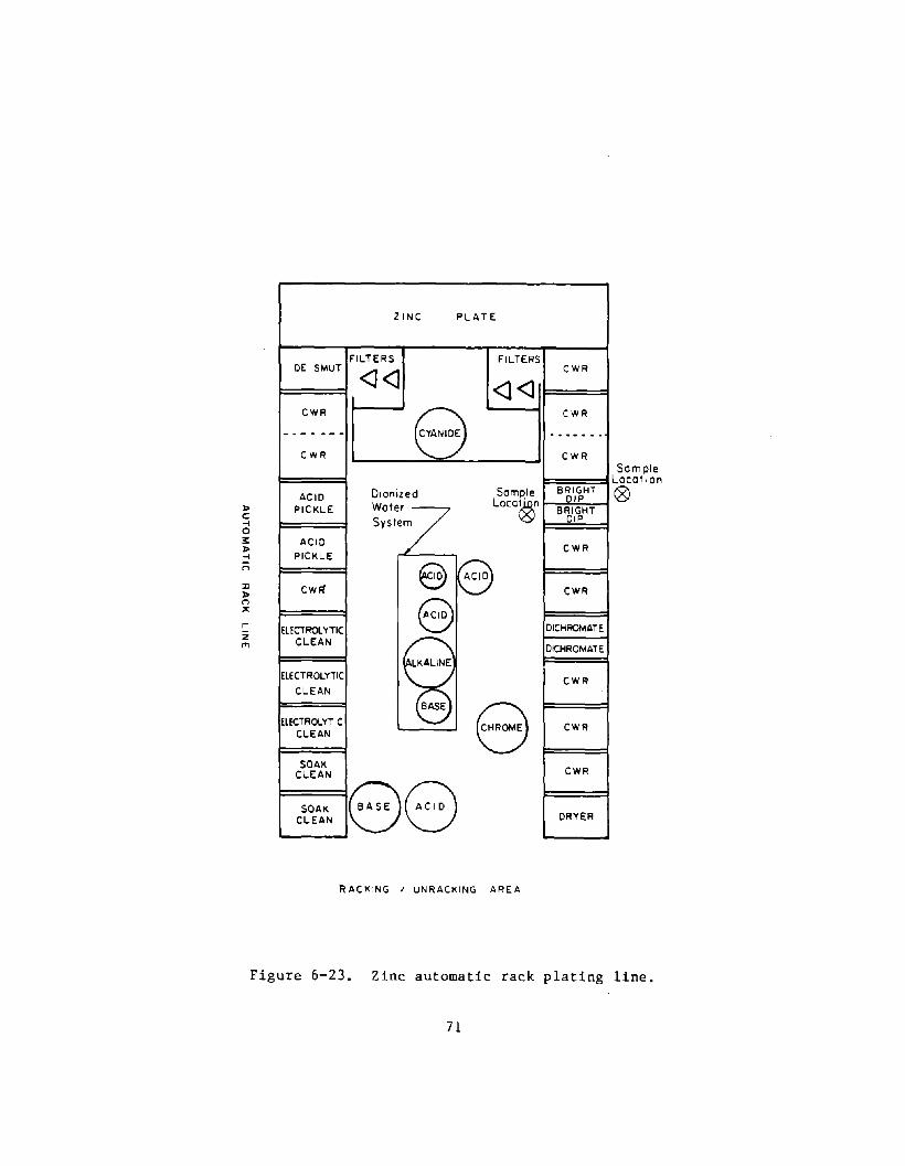
l> c: -< o lI: l> -< ;:;
r z
'"
ZINC PLAT E
FILTERS FILTERS DE SMUT
<l<l <l<J CWR
8 _. _ ..... --CWR
Dionlzed Semple ACID Loce~ PIC KLE wote,:?
Syslem
ACID
PICKLE e CwFf e e El ECTROl Hie
CLEAN
I~ ElECTROLYTIC
CLEAN
BASE
8 ElECTROlYTIC CLEAN
SOAK CLEAN
88 SOAK CLEAN
RACKING I UNRACKING AREA
CWR
CWR
.. _-_.-CWR
BRIGHT DIP
BRIGHT DIP
CWR
CWR
DICHAOMATE
DK:HRDMATE
CWR
CWR
CWR
DRYER
Sem pie Locallon
&>
Figure 6-23. Zinc automatic rack plating line.
71

72

Area samples for total zinc, total sodium, and particulate cyanide taken on the zinc plating rank are sholNn in Table 6-14. Samples were taken at four locations (see Figure 6-24) around the tank each day for three days. Levels for all substances sampled were near or below the detectable limit. Total zinc concentration averaged 0.003 mg/m 3 , sodium hydroxide concentrations averaged 0.047 mg/m 3, and the particulate cyanide concentrations averaged less than 0.006 mg/m3.
Table 6-14. Ai r sampling results - zinc plating (mg/m 3)
Sodium Particulate Zinc Hydroxide Cyanide
Geom. Geom. Geom. No. of Location Mean Range Mean Range Mean Range Samples
Tank 1J 0.003 <0.003 to 0.047 <0.007 to <0.006 <0.005 to 12 0.010 0.019 <0.007
* 12 samples were analyzed.
The data shows that mists and fumes from the low-cyanide zinc plating tank are very low. In fact, under normal operating conditions, the ventilation system (canopy hood and the slot hood) may not be necessary. However, as a precautionary measure, local ventilation is needed (in the event that acid were to be inadvertently added to the tank releasing cyanide into the room). The ventilation also helps to control noxious odors.
Acid Cleaning
In this study seven acid cleaning tanks (located at three separate plating facilities) were evaluated. Six tanks are used in preparation and one for metal finishing. Bath and tank parameters and the ventilation data for tanks are presented in Table 6-15. Acid cleaning is performed primarily to remove oil and light metal oxides from the basis metal by dipping or soaking the part s in a tank solution. The seven tanks surveyed consisted of three acid pickle, two acid dips, an acid etch, and a bright dip tank. Three tanks included hydrochloric acid only, two contained nitric acid only, and the others were combinations of nitric, sulfuric, and hydrofluoric acid.
73

Table 6-15. Acid cleaning tank parameters.
Basis metal Hydrogen chloride concentration (%)
Hydrogen fluoride concentration (%)
Nitric acid concentration (%)
Sulfuric acid concentration (%)
Temperature (oF) Tank width (ft) Tank length (ft) Tank volume (gal) Freeboard (in) Ventilation (local)
Exhaust rate (dm/ft2)
Agitation
Acid Pickle
lK
various 35
0
0
0
75 1.2 1.7 35 3 I-side
55
None
Acid Pickle
1M
steel 17
0
0
0
75 4 3 160 11 I-side
80
None
Bath Acid
Pickle IN
steel 17
0
0
0
75 4 3 160 11 I-side
80
Description Acid Acid
Dip Etch 6D 7H
aluminum various 0 0
13
43 0
22 28
75 70 3 3 2 3 100 150 10 4 I-Side/ 3-side push-pull 70 200
None None None
Nitric Dip 6F
aluminum 0
0
50
0
75 3 2 90 15 I-side
55
None
Bright Dip lP*
zinc 0
0
1
0
75 1.3 5 350
None
Yes
* lP is actually two tanks that are used alternately; the tank dimensions are for one tank.
All tanks except the bright-dip tank lP were equipped with local exhaust ventilation. The exhaust rate for the acid etch tank was 200 cfm/ft2 while the exhaust rate for the remaining six tanks ranged from 50 to 80 cfm/ft2. None of the tanks had covers or floating plastic balls. None were air agitated; however, there was considerable turbulance in bright-dip Tank lP due to the regular automatic emptying and filling of this tank.
Tanks 6D and 6F are shown in Figures 6-26 and 6-27. A 1/ 4t h inch thick polypropylene exhaust hood (Figure 6-25) extends along five tanks including 6D and 6F. The polypropylene hood is ll8-inches-long and has a lO-inch-high opening. A side view of the hood and tanks 6D and 6F is shown in Figure 6-26. The three-sided acid etch tank 7H from the second plant is shown in Figure 6-27.
Area sampling results for the acid tanks are presented in Table 6-16. Tank 6D was sampled one day with exhaust ventilation only, but on the second day push-pull ventilation was used.
74
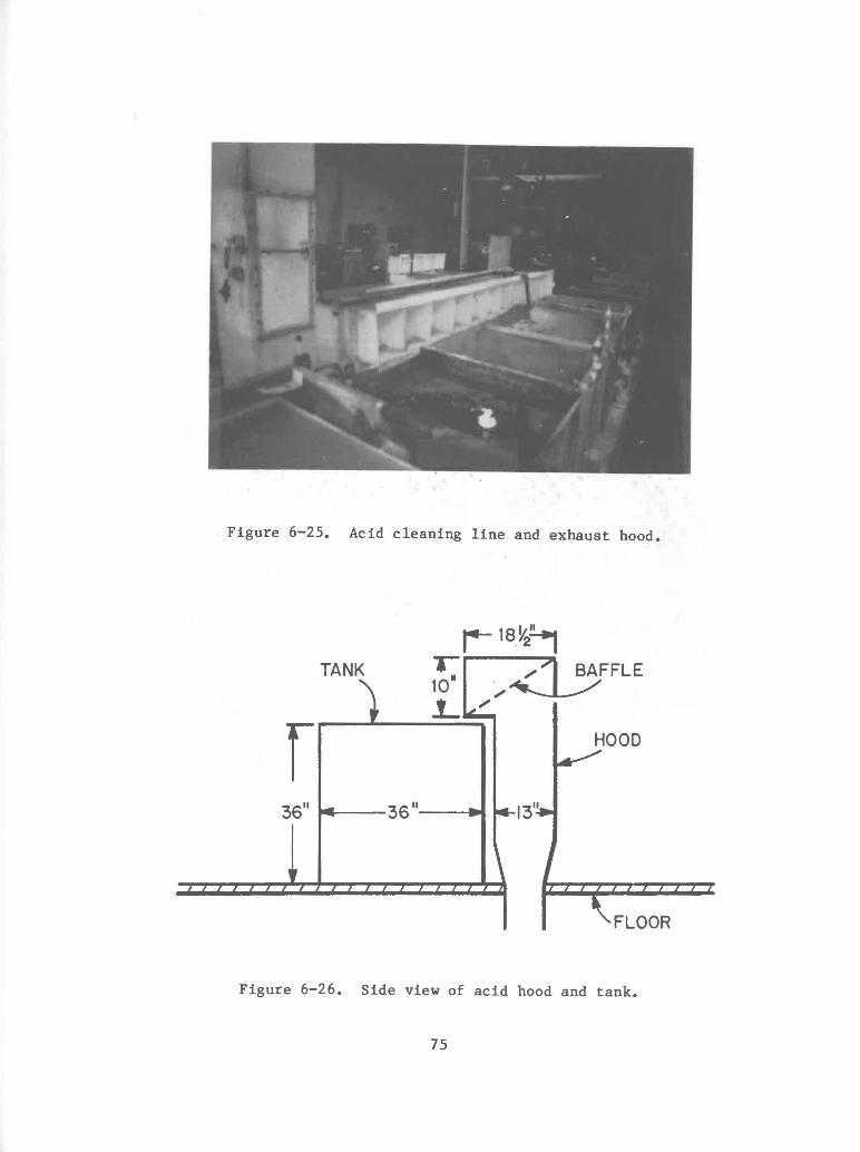
Figure 6-25. Acid cleaning line and exhaust hood.
TANK
r 36" 36"--....
FLOOR
Figure 6-26. Side view of acid hood and tank.
75

Figure 6-27. Tank 7H - acid etch.
76

Table 6-16. Air sampling results - acid tanks (mg/m3) •
Hydrochloric Acid Hydrofluoric Acid Nitric Acid Sulfuric Acid Sample Geom. No. of Geom. No. of Geom. No. of Geom. No. of Loc. Mean Range Samples Mean Range Samples Mean Range Samples Mean Range Samples
Tank lK 0.03 <0.02 to 5 0.04 <0.03 to 5 0.02 <0.02 to 5 0.09 0.11 0.03
Tank 1M 0.03 <0.01 to 12 0.57
Tank iN 0.16 0.01 to 12 0.80
..... ..... Tank IP 0.04 <0.006 to 0.04 0.03 to 6 0.54 6 0.10
Tank 6D 2.7 1 0.76 0.72 to 2 5.8 2.8 to 2 Exhaust
0.81 12 Only
Tank 6DX 1.2 1 0.47 0.43 to 2 2.4 0.74 to 2 Push Pull
Tank 6F 0.54 0.05 to 6 2.8
Tank 7H 0.17 0.14 to 4 <0.05 <0.05 to 4 0.19 0.08
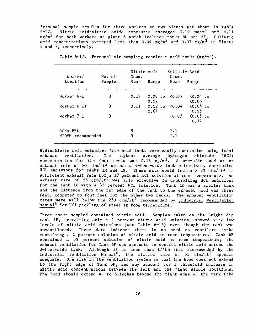
Personal sample results for three 6-17. Nitric acid/nitric oxide mg/m 3 for both workers at plant 6 acid concentrations averaged less 6 and 7, respectively.
workers at two plants are shown in Table exposures averaged 0.19 mg/m 3 and 0.11 which included tanks 6D and 6F. Sulfuric than 0.04 mg/m 3 and 0.05 mg/m 3 at Plants
Table 6-17. Personal air sampling results - acid tanks (mg/m3).
Nitric Acid Sulfuric Acid Worker/ No. of Geom. Geom.
Location Samples Mean Range Mean Range
Worker 6-1 3 0.19 0.08 to <0.04 <0.04 to 0.57 <0.05
Worker 6-II 3 0.11 0.02 to <0.04 <0.04 to 0.64 0.05
Worker 7-1 3 <0.05 <0.05 to 0.11
OSHA PEL 5 1.0 NIOSH recommended 5 1.0
Hydrochloric acid emissions from acid tanks were easily controlled using local exhaust ventilation. The highest average hydrogen chloride (HCl) concentration for the four tanks was 0.16 mg/m 3 • A one-side hood at an exhaust rate of 80 cfm/ft 2 across a 4-foot-wide tank effectively controlled HCI emissions for Tanks 1M and 1N. These data would indicate 80 cfm/ft2 is sufficient exhaust rate for a 17 percent HCl solution at room temperature. An exhaust rate of 55 cfm/ft2 was also effective in controlling HCl emissions for the tank IX with a 35 percent HCl solution. Tank 11< was a smaller tank and the distance from the far edge of the tank to the exhaust hood was three feet, compared to four feet for the other two tanks. The exhaust ventilation r.ates were well below the 250 cfm/ft 2 recommended by Industrial Ventilation Manual6 for HCI pickling of steel at room temperature.
Three tanks sampled contained nitric acid. Samples taken on the Bright dip tank lP, containing only a 1 percent nitric acid solution, showed very low levels of nitric acid emissions (see Table 6-16) even though the tank was unventilated. These data indicate there is no need to ventilate tanks containing a 1 percent solution of nitric acid at room temperature. Tank 6F contained a 50 percent solution of nitric acid at room temperature; the exhaust ventilation for Tank 6F was adequate to control nitric acid across the 3-foot-wide tank. Although it is less than 1/4th that recommended by the Industrial Ventilation Manual6 , the airflow rate of 55 cfm/ft2 appears adequate. One flaw in the ventilation system is that the hood does not extend to the right edge of Tank 6F, and may account for a threefold increase in nitric acid concentrations between the left and the right sample locations. The hood should extend 4- to 6-inches beyond the right edge of the tank (the
78

extra inches allow for bowing of the plastic tanks and for emissions caused by indoor air currents moving from left to right.)
Nitric acid emissions from the mixed acid tank 6D were well controlled with either exhaust only or push-pull ventilation. Push-pull ventilation, however, appeared to slightly improve control of nitric acid over exhaust only. Personal samples for workers using tanks 6D and 6F show average nitric acid concentrations of 1/20th the OSHA standard indicating satisfactory control of emissions from these tanks. Personal exposure data to nitric acid were probably higher than normal because Tank 6D was dumped on the last sampling day resulting in a fivefold increase over the previous two days.
Hydrogen fluoride emissions were measured on two tanks: emissions from Tank 7H were well controlled using three-sided local ventilation at an exhaust rate of 200 cfm/ft 2 and emissions from Tank 6D were satisfactorily controlled. Push-pull ventilation appeared to control these substances better than exhaust ventilation only. A 70 cfm/ft2 exhaust rate satisfactorily controlled HF emissions from Tank 6D, a mixed acid solution containing 13 percent hydrogen fluoride.
Sulfuric acid measurements were taken on two tanks with similar sulfuric acid concentrations in the baths: 28 percent in 7H and 22 percent in Tank 6D. However, sampling results for sulfuric acid emissions show great differences between the two tanks. Three-sided exhaust ventilation at 200 cfm/ft2 did an excellent job in controlling sulfuric acid to less than 0.08 mg/m 3 • On the other hand, sulfuric acid levels were very high for tank 6D with a one-sided hood at an exhaust rate of 70 cfm/ft2. Sulfuric acid levels with exhaust only average 5.8 mg/m3 with one sample as high as 12 mg/m 3 • A fair amount of sulfuric acid fumes were not being captured, and the ventilation system should be rated as less than adequate for the mixed acid tank 6D.
The following recommendations should improve the ventilation system for Tank 6D.
1. Turn the tanks 90° so the air is drawn across the narrower 24-inch dimension rather than the 36-inch dimension. Smoke tube tests indicate 'excellent capture at 24-inches from the hood but not at 36-inches from the hood.
2. An increased exhaust Ventilation7 recommends 70 cfm/ft 2 measured.)
volume may help slightly. Industrial 250 cfm/ft2 which is much greater than the
3. A push-pull system based on very limited data appears to upgrade the ventilation system. However, to be effective the quantity of supply air and the direction of the supply air jet for the push-pull ventilation system must be carefully controlled; too much air supply and a misdirected jet could actually increase fumes from the tank. (The quantity of supply air for Tank 6D was 11 cfm).
79

Despite high area sample concentrations for Tank 6D, personal samples on two acid line workers show low levels of sulfuric acid. This is due to the fact the acid line workers spend only a small percentage of their time at anyone tank.
The very low levels of sulfuric acid emissions from Tank 7H indicate the exhaust rate of 200 cfm/ft 2 for that size of tank may be much more than is necessary to control sulfuric acid fumes. Personal exposure indicates workers are satisfactorily protected from sulfuric acid emissions at this plant.
Caustic Cleaning
Three types of caustic cleaning tanks at one facility were evaluated: an electrocleaner, de-smut, and soak clean. Operating conditions, tank sizes, and ventilation data for each of the tanks are presented in Table 6-18. The three tanks had similar concentrations of hydroxides and Tank 1R contained a small amount of cyanide. Bath temperature was much higher for Tank lQ and IS than for Tank lB. All three tanks were equipped with one-sided local exhaust ventilation, but only Tank lQ had a cover. A schematic of this tank is shown in Figure 6-28.
Table 6-18. Caustic cleaning tank parameters.
Sodium/potassium hydroxide concentration (oz/gal)
Potassium cyanide concentration (oz/gal)
Temperature (OF) Tank width (ft) Tank length (ft) Tank volume (gal) Freeboard (in) Local ventilation Exhaust rate (cfm/ft 2) Covers
lQ Bath Description
lR Electrocleaner
8
150 2.5 2.5 130 3.5 I-sided 140 Yes
80
De-smut
6
1
75 2 2 90 15 I-sided 125 No
IS Soak
8
145 4 6 480 8 I-sided 80 No
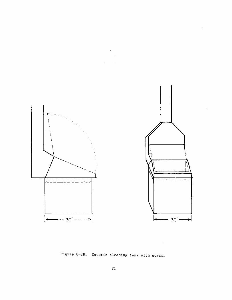
, I
\ \
1+(-- 30" ---->1
Figure 6-28. Caustic cleaning tank with cover.
81
30"~1

Area air sampling results are shown in Table 6-19. Area samples for all three tanks were taken along the front edge of the tank across from the exhaust hood, (approximately seven inches above the top of the tank). For tank lQ, the results show sodium hydroxide concentrations averaged 0.02 mg/m 3 with no parts in the tank and 0.54 mg/m 3 with dummy loads. These samples were taken with the cover generally closed. Area samples taken on Tank lR and IS show very low levels of potassium hydroxide.
Table 6-19. Ai r sampling results - caustic·tanks (mg/m3 )
Sodium Hydroxide Potassium Hydroxide
Tank No. of Geom. Geom. Sampled Samples Mean Range Mean Range Comments
lQ 6 <0.014 <0.014 to <0.022
lQX 2 0.15 <0.043 to 1.0
lR 10 <0.014 <0.01 <0.02
IS 17 <0.01 <0.01 0.02
OSHA PEL 2.0
One-sided local exhaust ventilation of 125 cfm/ft2 across a (lR) and an exhaust rate of 80 cfm/ft2 across a 4-foot-wide solution temperature of l45
DF were completely effective
potassium hydroxide. It appears that lower exhaust rates would also control hydroxide emissions into the workplace.
Cover down No parts in
tank. Cover down Dummy load
to
to
2-foot-wide tank tank (1S) with a
in controlling for these tanks
The results for the electrocleaner caustic tank (lQ) show a high rate of exhaust ventilation is needed for this tank as data show sodium hydroxide mists were very low without parts in the tank but were much higher with parts in t he tank. Industrial Ve ntila t ion6 recommends an exhaus t rate of 190 cfm/ft 2 (with a cover). These data would support the Industrial Ventilation6 recommendation; however, with a cover, it appears the exhaust rate could be reduced slightly to 140 cfrn/ft2.
Solvent Degreasing
A vapor degreasing tank, 5-feet by 8-feet by 8-feet-deep, equipped with a electrically operated roll-up cover and refrigerated cooling coils was evaluated. The tank contains tetrachloroethylene and is operated at 250
D
F temperature; vapor level is maintained about 30 inches below the top of the tank. The tank, shown in Figure 6-29, is not ventilated. Area samples for tetrachloroethylene were taken each day for three days at three locations on
82

the tank and at a fourth location in the general room air away from the tank. The results are shown in Table 6-20 .
Sample Location
Tank 7I Gen. Air Personal OSHA PEL
Figure 6-29 . Solvent degreaser with cover open.
Table 6-20. Air Sampling Results - Tetrachloroethylene Degreaser Tank (mg/m3)
No. of Geom. Samples Mean
9 470 3 69
Samples 2 100 678
NIOSH recommended 339
83
Range
100 - 1900 50 - 130 84 - 130

Area samples show satisfactory control of tetrachloroethylene at Location 1 (244 mg/m 3 ) and 3 (361 mg/m 3), as well as an acceptable level in the general room air '(77- ~g/m3)j however, tetrachloroethylene at Location 2 0,528 mg/m 3) ¥i!!'lS poorly controlled. This high concentration resulted from not fully closing the roll-up cover. Sample 2 was located at the edge of the tank next to the area that was not covered while sample Location 1 and 3 were located next to areas that were normally covered.
It is recommended that the cover be closed while the degreaser is operating which should reduce tetrachloroethylene emissions by a factor of 4 or more. Personal samples show that despite poor control where the tank is open, the exposure of the worker at the degreaser was only 1/6th the OSHA standard and 1/3rd the NIOSH recommended standard for tetrachloroethylene.
WORK PRACTICES
Five electroplating operations (including three hardchrome plants) were studied to assess work practices and related human factor considerations which are important to hazard prevention in the workplace. 7l ,40 In general, formal training programs for plating employees did not exist. The shop supervisor, foreman, or plant manager (or owner) were responsible for orienting employees to potential safety and health hazards and to the availability, use, and need for' personal protective equipment and other protective measures. The actual' health and safety program can best be illustrated by the following specific examples.
In Plant A, a hardchrome operation, the plant manager met with each new employee, apprising them of the plant' policies including aspects of personal safety, the potential for skin eruptions (chrome ulcers) which require a long time to heal, th~ need for frequent washing'of hands and the use of protective gloves. The plant foreman instructed workers in the various job tasks and the need and use of personal protective equipment. In practice, the foreman moved throughout the shop area, without protective glasses or gloves.
In Plant B, a hardchrome operation, an employee handbook is provided that clearly states company policies, rules, and practices giving heavy emphasis to safety and health matters as well as the general well-being of its workforce.
The plant manager and superintendent of different shops (including the plating one) are held accountable for the health/safety conditions in their areas of responsibility. Bonuses given for outstanding performance include efforts shown in the health/safety areas.
There is an active safety committee composed of workers from different company shops and shop superintendents who serve on a rotating basis. Shops are subject to monthly inspections with checklists designed to check on employee work habits, use of personal protective equipment, maintenance of plant machinery, and follow-through on previous recommendations. Recommendations from the safety committee are supplied to the insurer for their information and followup as well.
84
An emergency evacuation plan has been developed for the plating plant should there be a fire, or dangerous gas leak. The local fire department has toured the facility, noting the locations of the plating tanks and other equipment so as to avoid added problems in case of a fire emergency.
The workforce in the shop was a stable one; the shortest service time for those platers observed was 2-1/2 years.
Overall, sound safety and health procedures were followed at this plant. The superintendent and plant manager suggested that plant safety rules and constant encouragement and reminders were primary factors in promoting the good practices now in use.
At Plant C, there is no formal training program for workers. The shop supervisor is responsible for instructing the employees in the use of personal protective equipment and in the type of hazards found in the shop.
Worker turnover has been minimal. Most of the current platers are highly experienced with an average of 20 years in the plating shop. The platers like their work, consider themselves craftsmen in their trade, and seem to accept the risks as part of their job. The supervisor wore no protective clothing or equipment while in the shop area or when around the tanks. The platers wore vinyl-like aprons, rubber gloves, and sometimes face shields when performing tasks they felt required them, such as filling tanks or removing large parts.
In this plating shop, the "need" for an elaborate or strict health and safety program was not that evident despite the potential hazards that exist in the shop. The probable reasons for this are a stable, predictable work pace along with a stable, mature workforce. The problem is that if any of the above conditions are changed, the plating shop at this subject worksite would represent a higher risk work environment.
A number of good and poor work practices were found in the five electroplating plants. Some of the good work practices were:
o Rinsing the plated piece directly over the plating tank and allowing excess chromic acid to drain back into the tank. This lessened the potential contact with chromic acid in subsequent plating activity.
o Wearing gloves when adding water to a plating bath and frequently washing hands, especially after tasks that required the use of bare hands (e.g., unmasking parts after plating).
Poor work practices included:
o Wearing of cloth gloves when rubber gloves should be worn.
o Not always wearing safety glasses.
o Standing on the chromic acid plating tanks in guiding parts to certain locations. Because of the risk of an accidental'slip into the chromic acid bath, an alternative to standing on the tanks should be found.
85

o Using stand-up portable fans for moderating heat in the shop have the potential for disrupting the local exhaust ventilation. It is important that such fans not be placed in locations where fumes may be blown across plating tanks into the workers breathing zone or bench area.
Work practices among maintenance workers, who are called into the plating shop to do repairs, are of special importance. Because they may be unfamiliar with the unique hazards of a shop, they are often at greater risk than the platers in the shop. An example of this enhanced risk was observed at one plant. A thermal coil in one of the shop's new, man-size tanks began to deteriorate as the tank was filled with acid. Because this was considered a small emergency, two men from the maintenance shop were quickly called to pull the coil out of the tank before it was ruined. Without benefit of protective gear, they were allowed to climb up on the ledge of the large tank, lean over the opening, unscrew the tubing from inside the tank wall, and haul the coil out of the tank. The latter caused the acid to drain onto their hands and arms. One man continued to hold the dripping coil in his bare hands. After completion of the job, the two maintenance men were observed blowing on their hands. Maintenance people entering plating areas should be thoroughly briefed about the hazards and required to wear appropriate personal protective equipment.
Inspection and maintenance of the ventilation system for the plating tanks was found to vary considerably. The ventilation system was checked monthly at one plant, and at a second plant a scheduled maintenance procedure was in effect for the ventilation control system, with a plant person specifically assigned to cover this responsibility. However, inspection and preventive maintenance of the ventilation system was almost nonexistent at most plants.
The following procedures are recommended to increase good work practices in plating operations. 71
Periodic surveys of good work could be accomplished by using conjunction with the manager production and job status.
practices should be performed. This a simple checklist and carried out in or supervisor's routine surveys of
2. A "Chemical Hazard Data Sheet" should be prepared for each chemical to which a worker is exposed, and the safety and health effects of the material explained to workers.
3. The NIOSH pamphlet entitled "NIOSH Good Work Electroplaters" (1977) would be an excellent document to receive and to discuss among themselves and with or managers. Solicitation of the views of workers ideas for reducing potential job hazards or improving practices would also be beneficial.
Practices for for each worker
shop supervisors regarding their
on existing work
In several chemicals. which also equirment.
cases there were problems with the handling and storage of In one establishment, chemicals were stored in a small outbuilding housed the employee lunchroom, locker facilities and general
Chemical storage was disorganized; integrity of containers of old
86

chemicals was questionable, and the dry chemical storage was next to the lunch . area. It was recommended that chemical storage be kept away from the eating area and stored in an orderly fashion, and that chemicals no longer in use be removed. Dry materials should be stored in closed, marked containers.
In another p~ant, workers delivering the chemicals to the shop, unload the drums inside the shop, and place the drums on the floor or on a pallet near the entrance doors. These drums stand there for hours, or even days, until the solution maintenance men pick them up and use them. This creates the potential for an emergency situation because there is heavy traffic in the entrance way and if a dolly or cart hits a cyanide and an acid drum simultaneously, their contents may spill on the floor, and hydrogen cyanide (HeN) may be liberated. It was recommended that an appropriate storage place be established for chemicals delivered to the plating area.
The Electroplating Engineering Handbook (Ref. 3, p. 320) discusses the special precautions which should be taken when cyanides are present. Plating and metal pretreatment tanks were correctly and clearly labeled in almost all cases. However, at one plant with tanks side by side, in long rows, a number of tanks either had no label or incorrect labels. One tank labeled "Danger -Acid" actually contained cold water while the tank next to it, with no warning label, contained acid. All tanks should be provided with clear, up-to-date labels attached near the surface of the tank at eye level. Labels on the sides of the tank may not be sufficient because they are not readily noticeable.
PERSONAL PROTECTIVE EQUIPMENT
Generally, all five plating shops surveyed provided safety glasses and protective gloves, and all but one provided clean uniforms (issued daily). Bump hats, face shields, dust masks, aprons, safety shoes, and rubber boots were available from at least one of the shops.
The actual use of personal protective equipment ranged from excellent at one plant to poor at several. At one plant, workers were rarely seen without safety glasses. At the second plant, only 50 percent of the platers always wore safety glasses and a similar percentage wore rubber gloves when working over the electroplating tanks. In a third plating shop (hardchrome), Chromium VI spot tests made on the palms and backs of the hands of four workers were found to be positive. Workers who wore protective gloves most of the day had much weaker Chromium VI responses than those who frequently removed their gloves to work, and workers who reported using their gloves while performing their job tasks reported to have a rare incidence of chrome ulcers. 40
The plating operations surveyed were most in need of the following personal protec ti ve equipment: rubber boot s and safe ty shoes. In addi t ion, employees should be encouraged to minimize exposing their hands to plating solutions by wearing their work gloves and by avoiding gross contamination of the gloves' inner linings. Where many of the parts that are handled are bulky and quite heavy, safety shoes with steel reinforced toes are recommended.
87
At one plating shop, side shields needed to be added to safety glasses. Finally, respirators should be available, fit tested, and used by workers who may be exposed to harmful levels of air-contaminants. Respirators are intended to be worn for infrequent short periods such as maintenance operations,3 and are indispensable for cleaning out tanks and other jobs requiring short-time exposure to high concentrations of toxic substances.
HYGIENE PROCEDURES
All the plating shops provided a lunchroom or locker area for employees. At one plating facility, the "eating room" in the building adjacent to the plant, was observed to be quite filthy and in a general state of disarray. A spot-test on the tabletop where food is consumed was strongly positive for chromium. Additional sources of chromium contamination resulted from the collection of soiled work clothes on the floor area, chemical storage in an open room adjacent to the break area, and the personal hygiene and housekeeping habits of the employees. It was recommended that this entire area be thoroughly cleaned and that routine "housekeeping" procedures be established; that a collection receptacle be provided for the soiled uniforms presently being collec ted in piles on the .. ea ti ng room" floor; and because Chromium VI spot testing in the plant shop revealed the presence of chromium on most every surface that was tested; eating, drinking, and smoking in the plating area should be discouraged.
In a second plant located in the southern Unites States, an air conditioned room separate from the plating area was available to workers for lunch or breaks. This break room is particularly valuable in offering some relief from summer heat when plating floor temperatures can be quite high. Daytime temperatures during the survey at this plant were 90 to 96°F with 60 percent relative humidity. Employees were also provided with shower facilities.
Workers at a third facility were permitted to eat in the plating shop and many do so even though there was a small lunchroom about a minute's walk from the plating shop. Workers at this plant may take showers after work and change their clothing; however, many prefer to go home in their working clothes.
MONITORING
None of the plating plants surveyed had a display panel or other direct feedback means to indicate the performance efficiency of the ventilation con t rol sys tem or whether it was even operating. One company maintenance department did perform monthly velometer checks; however, this was the exception. 71
Industrial hygiene monitoring of air contaminants was conducted at one plant semi -annually by the company's insure r. In a second plant the indust rial hygiene department takes air samples every two years or if workers suspect increased air contamination. A third plating shop has been occasionally inspected by the state occupational health department including industrial hygiene sampling. But in most plating establishments, there is little or no industrial hygiene sampling or other monitoring of the workplace air
88

contaminants. Local exhaust ventilation for plating and cleaning tanks should be checked at least monthly.
89
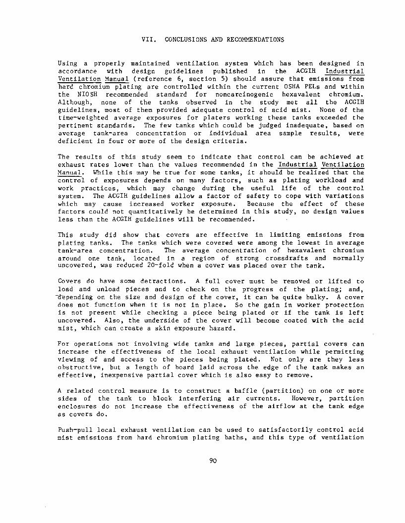
VII. CONCLUSIONS AND RECOMMENDATIONS
Using a properly maintained ventilation system which has been designed in accordance with design guidelines published in the ACGIH Industrial Ventilation Manual (reference 6, section 5) should assure that emissions from hard chromium plating are controlled within the current OSHA PELs and within the NIOSH recommended standard for noncarcinogenic hexavalent chromium. Although, none of the tanks observed in the study met all the ACGIH guidelines, most of them provided adequate control of acid mist. None of the time-weighted average exposures for platers working these tanks exceeded the pertinent standards. The few tanks which could be judged inadequate, based on average tank-area concentration or individual area sample results, were deficient in four or more of the design criteria.
The results of this study seem to indicate that control can be achieved at exhaust rates lower than the values recommended in the Industrial Ventilation Manual. While this may be true for some tanks, it should be realized that the control of exposures depends on many factors, such as plating workload and work practices, which may change during the useful life of the control system. The ACGIH guidelines allow a factor of safety to cope with variations which may cause increased worker exposure. Because the effect of these factors could not quantitatively be determined in this study, no design values less than the ACGIH guidelines will be recommended.
This study did show that covers are effective in limiting emissions from plating tanks. The tanks which were covered were among the lowest in average tank-area concentration. The average concentration of hexavalent chromium around one tank, located in a region of strong crossdrafts and normally uncovered, was reduced 20-fold when a cover was placed over the tank.
Covers do have some detractions. A full cover must be removed or lifted to load and unload pieces and to check on the progress of the plating; and,
-d-epending on the size and design of the cover, it can be quite bulky. A cover does not function when it is not in place. So the gain in worker protection is not present while checking a piece being plated or if the tank is left uncovered. Also, the underside of the cover will become coated with the acid mist, which can create a skin exposure hazard.
For operations not involving wide tanks and large pieces, partial covers can increase the effectiveness of the local exhaust ventilation while permitting viewing of and access to the pieces being plated. Not only are they less obstructive, but a length of board laid across the edge of the tank makes an effective, inexpensive partial cover which is also easy to remove.
A related control measure is to construct a baffle (partition) on one or more sides of the tank to block interfering air currents. However, partition enclosures do not increase the effectiveness of the airflow at the tank edge as covers do.
Push-pull local exhaust ventilation can be used to satisfactorily control acid mist emissions from hard chromium plating baths, and this type of ventilation
90

is recommended for all hard chromium plating tanks wider than 48 inches. However, direction of the supply air jet must be designed to avoid bounceback. Also, the combined volume of supply air and entrained air should not exceed the capacity of the exhaust hood. Until current NIOSH research on push-pull ventilation is concluded, design guidelines in the IVM should be followed.
91

VIII. REFERENCES
1. u. S. Envi ronmental Protection Agency. Economic Analysi s of Proposed Pretreatment Standards for Existing Sources of the Electroplating Point Source Category. Report EPA 230/1-78-001. Washington, D. C., 1977.
2. Craig, A. and R. W. L. Jones: Occupational Health in the Metal Finishing Industry. Occup. Health, 7: 215-223, 1971.
3. Graham, A •. K. (Ed.): Electroplating Engineering Handbook. Reinhold Publishing Corp., New York, 1955.
4. Sittig, M.: Electroplating and Related Metal Finishing. Noyes Data Corporation, Park Ridge, New Jersey, 1978.
5. U. S. Environmental Protection Agency. Development Document for Existing Source Pretreatment Standards for the Electroplating Point Source Category. Report EPA 440/1-79/003, Washington, D. C., 1979.
6. Industrial Ventilation. A Manual of Recommended Practices (16th Ed.). Committee of Industrial Ventilation. American Conference of Governmental Industrial Hygienists, Lansing, Michigan, 1980.
7. Jackson, C. M., C. L. Faust, and R. H. Cherry, Jr.: Environmental Assessment of Emissions from Electroplating and Associated Operations. EPA Publ. No. IERL-C-167. U. S. Environmental Protection Agency, Cincinnati, Ohio, 1976.
8. Jager, L. E.: Hazards in the Plating Industry. Occup. Health Rev. 18: 3-10, 1966.
9. Burges, D. C. L.: Manufacturing Processes - Electroplating. J. Soc. Occup. Med. ~:114-ll7, 1977.
10. Blair, D. R.: Principles of Metal Surface Treatment and Protection. Pergamon Press, Oxford, 1972.
11. Swalheim, D. A. : Electrochemistry for Electroplaters. American Electroplaters Society, Inc. Winter Park, Florida, 1969.
12. Bloomfield, J.J. and W. Blum: Health Hazards in Chrome Plating. Public Health Reports ~(36):2330-2347, 1928.
13. Blair, J.: Chrome Ulcers, Report of Twelve Cases. J. Am. Med. Assoc. ~: 1927-1928, 1928.
14. Dixon, F.W.: Perforation of the Nasal Septum in Chromium Workers, Report of Eighteen Cases. ~. Am. Med. Assoc. ~:837-838, 1929.
15. Medical Inspectorate of Factories: Chrome Plating and Anodic Oxidation. ~. Ind. Hyg. ~:314-3l5, 1930.
92
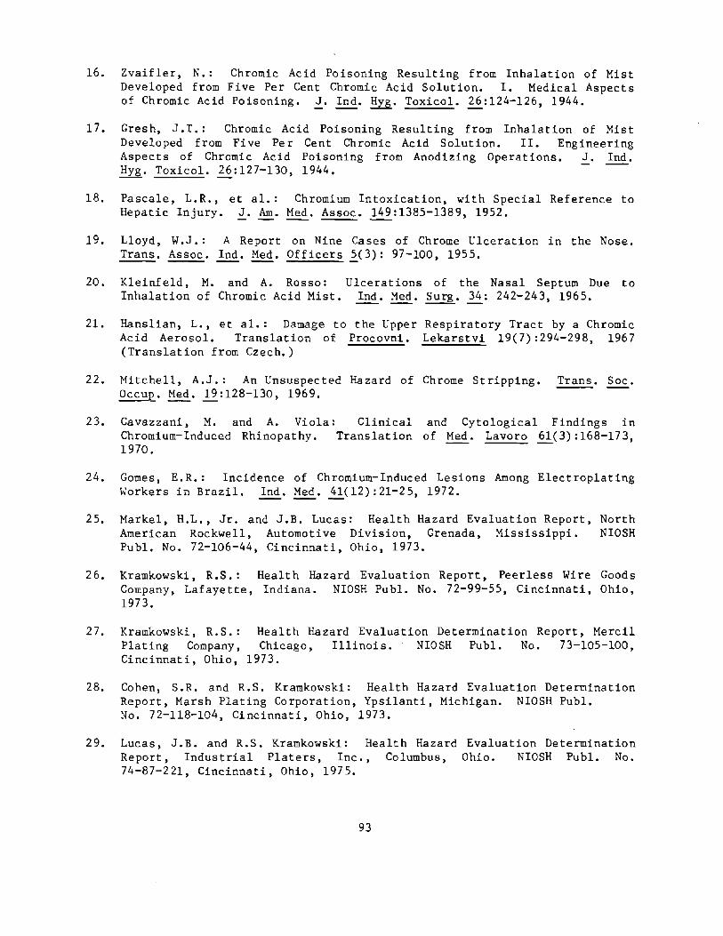
16. Zvaifler, N.: Chromic Acid Poisoning Resulting from Inhalation of Mist Developed from Five Per Cent Chromic Acid Solution. I. Medical Aspects of Chromic Acid Poisoning. ~. Ind. Hyg. Toxicol. ~:124-126, 1944.
17. Gresh, J. T. : Chromic Acid POisoning Resulting from Inhalation of Mist Developed from Five Per Cent Chromic Acid Solution. II. Engineering Aspects of Chromic Acid Poisoning from Anodizing Operations. J. Ind. Hyg. Toxicol. ~:127-l30, 1944.
18. Pascale, L.R., Hepatic Injury.
et a1.: Chromium Intoxication, with Special Reference to 2. Am. Med. Assoc. 149:1385-1389, 1952.
19. Lloyd, W.J.: A Report on Nine Cases of Chrome Ulceration in the Nose. Trans. Assoc. Ind. Med. Officers ~(3): 97-100, 1955.
20. Kleinfeld, M. and A. Rosso: Ulcerations of the Nasal Septum Due to Inhalation of Chromic Acid Mist. Ind. Med. Surg. ~: 242-243, 1965.
21. Hanslian, L., et al.: Damage to the Upper Respiratory Tract by a Chromic Acid Aerosol. Translation of Procovni. Lekarstvi 19(7):294-298, 1967 (Translation from CZech.)
22. Mitchell, A.J.: An Unsuspected Hazard of Chrome Stripping. Trans. Soc.
23.
Occup. Med. 1i:128-l30, 1969.
Cavazzani, M. Chromium-Induced 1970.
and A. Viola: Rhinopathy.
Clinical and Cytological Findings in Translation of Med. Lavoro ~(3) :168-173,
24. Gomes, E.R.: Incidence of Chromium-Induced Lesions Among Electroplating Workers in Brazil. Ind. Med. ~(l2) :21-25, 1972.
25. Markel, H.L., Jr. and J.B. Lucas: Health Hazard Evaluation Report, American Rockwell, Automotive Division, Grenada, ~ississippi.
Publ. No. 72-106-44, Cincinnati, Ohio, 1973.
North NIOSH
26. Kramkowski, R.S.: Health Hazard Evaluation Report, Peerless Wire Goods Company, Lafayette, Indiana. NIOSH Publ. No. 72-99-55, Cincinnati, Ohio, 1973.
27. Kramkowski, R.S.: Plating Company, Cincinnati, Ohio,
Health Hazard Evaluation Determination Report, Mercil Chicago, Illinois. NIOSH Publ. No. 73-105-100,
1973.
28. Cohen, S.R. and R.S. Kramkowski: Health Hazard Evaluation Determination Report, Marsh Plating Corporation, Ypsilanti, Michigan. NIOSH Publ. No. 72-118-104, Cincinnati, Ohio, 1973.
29. Lucas, J.B. and R.S. Kramkowski: Health Hazard Evaluation Determination Report, Industrial Platers, Inc., Columbus, Ohio. NIOSH Publ. No. 74-87-221, Cincinnati, Ohio, 1975.
93

30. Royle, H.: Toxicity of Chromic Acid in the Chromium Plating Industry. Environ. Res. 10:39-53, 1975.
31. Ibid. 141-163.
32. Roper, P.: Health Hazard Electric Company, Waynesboro, Cincinnati, Ohio, 1976.
Evaluation Virginia.
Determination NIOSH Publ.
Report, General No. 74-129-268,
33. Gilles, D. and E. Philbin: Health Hazard Evaluation Determination Report, TRW Incorporated, Philadelphia, Pennsylvania. NIOSH Publ. No. 76-61-337, Cincinnati, Ohio, 1976.
34. Gunter, B.J.: Health Hazard Evaluation Determination Report, Yarter-Tek Corporation, Denver, Colorado. NIOSH Publ. No. 78-53-510, Cincinnati, Ohio, 1978.
35. Pryor, P.: Hazard Evaluation and Technical Assistance Report, Package Machinery Company, East Longmeadow, Massachusetts. NIOSH Publ. NO. TA77-8l, Cincinnati, Ohio, 1978.
36. Blair, A. and T.J. Mason: with Metal Electroplating 1980.
Cancer Mortality Industries. Arch.
in United States Counties Env. Health E(2) :92-94,
37. Blair, A.: Mortality Among Workers in the Metal Polishing and Plating Industry, 1951-1969. J. Occup. Med. ~(3):158-162, 1980.
38. Dalager, N .A., et al.: Cancer Mortality Among Workers Exposed to Zinc Chromate Paints. J. Occup. Med. ~:25-29, 1980.
39.
40.
41.
Silverstein, M., et al.: Electroplating Plant. 4):156-165, 1981.
Mortality Among Workers in a Die-Casting and Scand. J. Work Environ. Health ~(Suppl.
Ahrenholz, S. and Chrome Platers, 81-085-889, 1981.
K.E. Anderson: Health Hazard Evaluation Report, Valley Bay City, Michigan. DHHS, PHS, NIOSH Publ. No.
Franchini, I. , et al.: Workers; Initial Findings. 1983.
Mortality Scand. J.
Experience Among Chrome-Plating Work Environ. Health .2.:247-252,
42. Criteria for a Recommended Standard •••. Occupational Exposure to Chromium (VI). DHEW, PHS, CDC, NIOSH Publ. No. 76-129, 1975.
43. Criteria for a Recommended Standard .... Occupational Exposure to Chromic . Acid. DHEW, PHS, NIOSH Publ. No. HS~ 73-11021, 1973.
44. Occupational Diseases - A Guide to Their Recognition, DHEW, PHS, CDC, NIOSH, Cincinnati, Ohio. DHEW (NIOSH) 77-181, 1977.
94
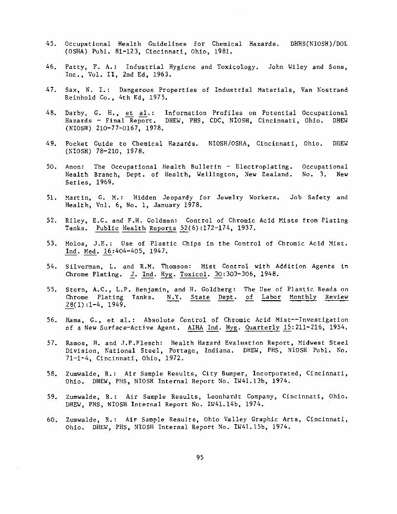
45. Occupational Health Guidelines for Chemical Hazards. (OSHA) Publ. 81-123, Cincinnati, Ohio, 1981.
DHHS(NIOSH)/DOL
46. Patty, F. A.: Industrial Hygiene and Toxicology. John Wiley and Sons, Inc., Vol. II, 2nd Ed, 1963.
47. Sax, N. 1.: Dangerous Properties of Industrial Materials, Van Nostrand Reinhold Co., 4th Ed, 1975.
48. Darby, G. H., ~ a1.: Information Profiles on Potential Occupational Hazards - Final Report. DHEW, PHS, CDC, NIOSH, Cincinnati, Ohio. DHEW (NIOSH) 210-77-0167, 1978.
49. Pocket Guide to Chemical Hazards. (NIOSH) 78-210, 1978.
NIOSH/OSHA, Cincinnati, Ohio. DHEW
50. Anon: The Occupational Healt h Branc h, Dept. of Series, 1969.
Health Bulletin - Electroplating. Health, Wellington, New Zealand.
Occupational No.3. New
51. Martin, G. M.: Hidden Jeopardy for Jewelry Workers. Job Safety and Health, Vol. 6, No. I, January 1978.
52. Riley, E.C. and F.H. Goldman: Control of Chromic Acid Mists from Plating Tanks. Public Health Reports ~(6):172-l74, 1937.
53. Molos, J.E.: Use of Plastic Chips in the Control of Chromic Acid Mist. Ind. Med. ~:404-405, 1947.
54. Silverman, L. and R.M. Thomson: Mist Control with Addition Agents in Chrome Plating. ~. Ind. Hyg. Toxicol. 30:303-306, 1948.
55. Stern, A.C., L.P. Benjamin, and Chrome Plating Tanks. N.Y. ~(1):1-4, 1949.
H. Goldberg: State Dept.
The Use of Plastic Beads on of Labor Monthly Review
56. Rama, G., et a1.: Absolute Control of Chromic Acid Mist--Investigation of a New Surface-Active Agent. AlHA Ind. Hyg. Quarterly ~:2ll-2l6, 1954.
57. Ramos, H. and J.P.Flesch: Health Hazard Evaluation Report, Midwest Steel Division, National Steel, Portage, Indiana. DHEW, PHS, NIOSH Pub1. No. 71-1-4, Cincinnati, Ohio, 1972.
58. Zumwalde, R.: Air Sample Results, City Bumper, Incorporated, Cincinnati, Ohio. DHEW, PHS, NIOSH Internal Report No. IW4l.13b, 1974.
59. Zumwalde, R.: Air Sample Results, Leonhardt Company, Cincinnati, Ohio. DHEW, PHS, NIOSH Internal Report No. IW4l.l4b, 1974.
60. Zumwalde, R.: Air Sample Results, Ohio Valley Graphic Arts, Cincinnati, Ohio. DHEW, PHS, NIOSH Internal Report No. IW41.15b, 1974.
95

61. Zumwa1de, R.: Air Sample Results, Porter-Guertin Company, Cincinnati, Ohio. DHEW, PHS, NIOSH Internal Report No. IW41.12b, 1974.
62. Zumwa1de, R.: Air Sample Results, R.A. Heller Company, Cincinnati, Ohio. DHEW, PHS, NIOSH Internal Report No. IW-41.1lb, 1984 ..
63.
64.
65.
66.
67.
68.
Zumwa1de, R.: Preliminary Industrial Incorporated, Cincinnati, Ohio. DHEW, 11\1'41. 13a, 1974.
Hygiene Survey of City Bumper, PHS, NIO SH Internal Report No.
Zumwa1de, Company, 11\1'41. 14a,
R.: Preliminary Cincinnati, Ohio. 1974.
Industrial Hygiene DHEW, PHS, NIOSH
Survey Internal
of Leonhardt Report No.
Zumwalde, R.: Preliminary Industrial Graphic Arts, Cincinnati, Ohio. DHEW, IW41.15a, 1974.
Hygiene Survey of Ohio Valley PHS, NIOSH Internal Report No.
Zumwalde, Company, IW41. 12a,
R. : Preliminary Industrial Hygiene Survey of Porter-Guertin Cincinnati, Ohio. DHEW, PHS, NIOSH Internal Report No. 1974.
Zumwalde, R.: Preliminary Industrial Hygiene Survey of R.A. Heller, Cincinnati, Ohio. DHEW, PHS, NIOSH Internal Report No. IW41.11a, 1974.
Guillemin, M.P. and M. Berode: A Study of the Difference Exposure in Workers in Two Types of Electroplating Process. ~. ~:105-112, 1978.
in Chromium Ann Occup.
69. NIOSH Manual of Analytical Methods. DHHS (NIOSH) 78-175/79-141/80-125/81- 100. Vo1s. 4 - 7, NIOSH, Cincinnati, Ohio, 1978.
70. Metal Finishing Guidebook and Directory. Metals and Plastics Publication, Inc. Hackensack, New Jersey, 1977.
71. Cohen, A., F. Dukes-Dobos, and V. Putz-Anderson: Four Trip Reports dated 5/28/81, 8/25/81, 11/3/81, and 12/22/81, NIOSH, Cincinnati, Ohio.
96

APPENDIX A
Sampling Results
97
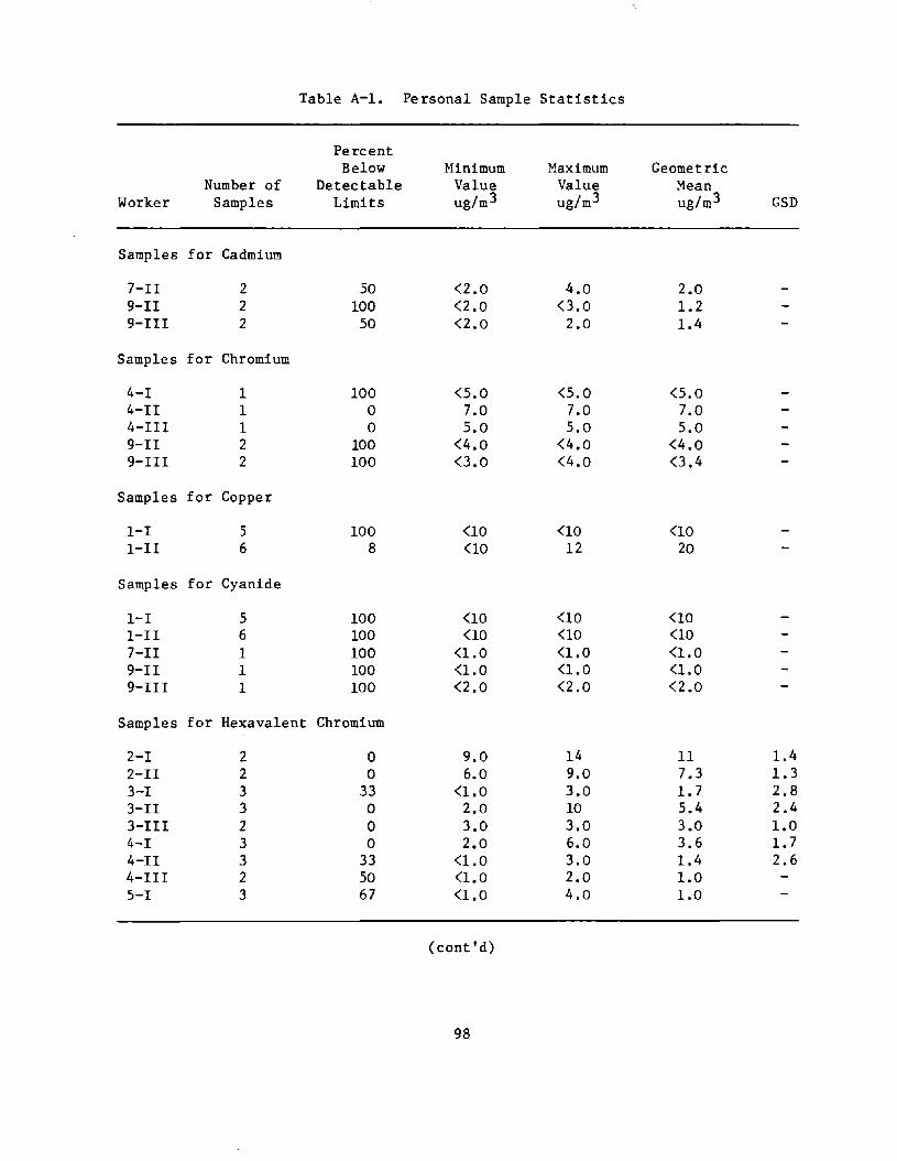
Table A-I. Personal Sample Statistics
Percent Below Minimum Maximum Geometric
Number of Detectable Value Value Mean Worker Samples Limits ug/m3 ug/m3 ug/m3 GSD
Samples for Cadmium
7-II 2 50 <2.0 4.0 2.0 9-II 2 100 <2.0 0.0 1.2 9-III 2 50 <2.0 2.0 1.4
Samples for Chromium
4-1 1 100 <5.0 <5.0 <5.0 4-II 1 0 7.0 7.0 7.0 4-III 1 0 5.0 5.0 5.0 9-II 2 100 <4.0 <4.0 <4.0 9-III 2 100 0.0 <4.0 0.4
Samples for Copper
I-I 5 100 <10 <10 <10 I-II 6 8 <10 12 20
Samples for Cyanide
I-I 5 100 <10 <10 <10 I-II 6 100 <10 <10 <10 7-II 1 100 <1.0 <1.0 <1.0 9-II 1 100 <1.0 <1.0 <1.0 9-II1 1 100 <2.0 <2.0 <2.0
Samples for Hexavalent Chromium
2-1 2 0 9.0 14 11 1.4 2-II 2 0 6.0 9.0 7.3 1.3 3-1 3 33 <1.0 3.0 1.7 2.8 3-II 3 0 2.0 10 5.4 2.4 3-II1 2 0 3.0 3.0 3.0 1.0 4-1 3 0 2.0 6.0 3.6 1.7 4-II 3 33 <1.0 3.0 1.4 2.6 4-II1 2 50 (1.0 2.0 1.0 5-1 3 67 <1.0 4.0 1.0
(cont'd)
98
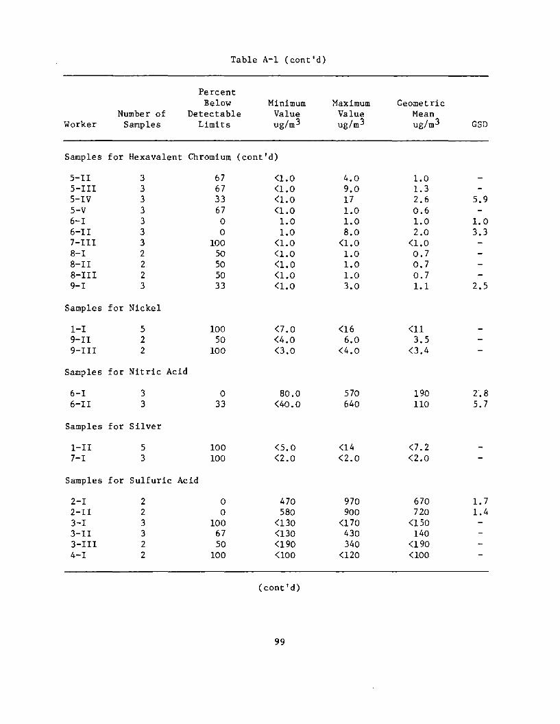
Table A-I (cont'd)
Percent Below Minimum Maximum Geometric
Number of Detectable Value Value Mean Worker Samples Limits ug/m3 ug/m3 ug/m 3 GSD
Samples for Hexavalent Chromium (cont'd)
5-II 3 67 <1.0 4.0 1.0 S-III 3 67 <1.0 9.0 1.3 5-IV 3 33 <1.0 17 2.6 5.9 S-V 3 67 <1.0 1.0 0.6 6-1 3 0 1.0 1.0 1.0 1.0 6-II 3 0 1.0 8.0 2.0 3.3 7-III 3 100 <1.0 <1.0 <1.0 8-1 2 50 <1.0 1.0 0.7 8-II 2 50 <1.0 1.0 0.7 8-III 2 50 <1.0 1.0 0.7 9-1 3 33 <1.0 3.0 1.1 2.5
Samples for Nickel
I-I 5 100 <7.0 <16 <11 9-II 2 50 <4.0 6.0 3.5 9-III 2 100 0.0 <4.0 0.4
Samples for Nitric Acid
6-1 3 0 80.0 570 190 2.8 6-II 3 33 <40.0 640 110 5.7
Samples for Silver
I-II 5 100 <5.0 <14 <7.2 7-1 3 100 <2.0 <2.0 <2.0
Samples for Sulfuric Acid
2-1 2 0 470 970 670 1.7 2-II 2 0 580 900 720 1.4 3-1 3 100 <130 <170 <150 3-II 3 67 <130 430 140 3-III 2 50 <190 340 <190 4-1 2 100 <100 <120 <100
(cont'd)
99

Table A-I (cont'd)
Percent Below Minimum ~1aximum Geometric
Number of Detectable Value Value Mean Worker Samples Limits ug/m3 ug/m3 ug/m3 GSD
Samples for Sulfuric Acid (cont'd)
4-II 2 100 <100 <120 <100 4-111 1 100 <100 <100 <100 5-1 3 100 <52 (53 (52 5-II 3 67 (52 61 (52 5-III 3 100 (51 (58 <54 5-IV 3 100 <52 <53 <52 5-V 3 100 (51 <52 <52 6-1 3 100 (40 <50 (43 6-II 3 100 (40 <50 (43 7-1 3 67 (47 106 (47 8-1 2 100 (1l0 <140 <120 8-II 2 100 <1l0 <140 <120 8-III 2 100 (120 (140 (130
Samples for Tetrachloroethylene
7-IV 2 0 84* 130* 100* 1.4
* mg/m3
100

Table A-2. Tank-Area Sample Statistics
Percent Below Minimum Maximum Geometric
Number of Detectable Value Value Mean Tank Samples Limits ug/m3 ug/m3 ug/m3 GSD·
Samples for Cadmium
7D 6 100 <2.0 0.0 <2.6 7E 6 100 0.0 0.0 0.0 9C 4 75 <2.0 .15.0 2.0 9B 7 100 <2.0 <2.0 <2.0
Samples for Chromium
3B 6 17 <7.0 120 20 3.5 3C 6 17 <8.0 77 17 3.0 3D 6 17 <8.0 380 46 5.5 4A 2 0 6.0 32 14 3.3 4B 3 33 <6.0 56 15 4.4 4E 3 0 25 36 29 1.2 4F 3 67 <6.0 11 <6.0 4G 3 0 39 190 87 2.2 4H 3 100 <5.0 <7.0 <6.0 SA 2 0 3.0 9.0 5.2 2.2 5B 3 33 0.0 10 5.1 2.9 5C 3 67 0.0 10 0.0 5D 3 67 0.0 12 3.0 6A 3 0 2.0 10 4.3 2.2 6B 9 0 2.0 500 42 8.0 9A 6 0 1400 7100 3800 1.8 9AX 1 100 <8.0 <8.0 <8.0
Samples for Copper
IF 17 100 <10 <10 <10 IE 10 100 <10 <10 <10 7F 3 100 0.0 0.0 <3.0
Samples for Cyanide
1J 12 100 <5.0 <7.0 <6.0 IF 17 100 <10 <10 <10 IE 10 100 <10 <10 <10
(cont'd)
101
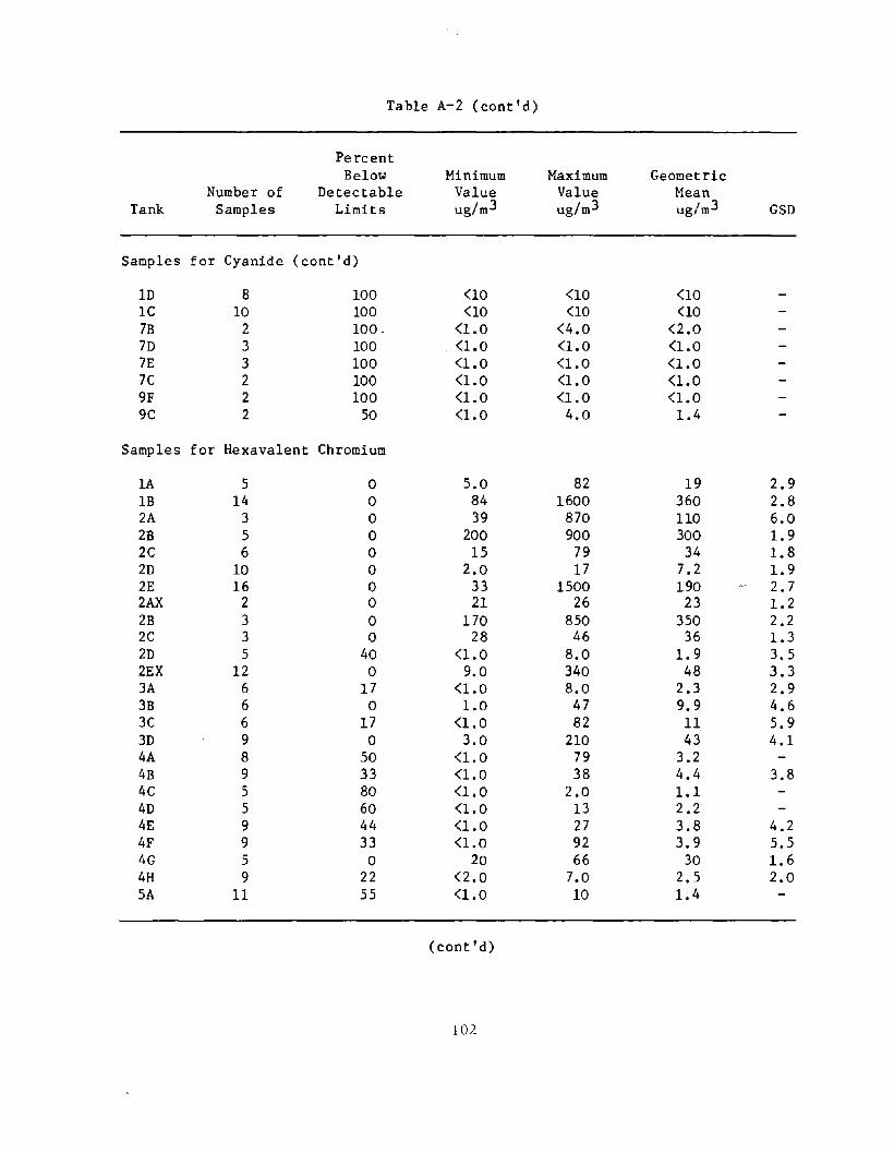
Table A-2 (cont'd)
Percent Below Minimum Maximum Geometric
Number of Detectable Value Value Mean Tank Samples Limits ug/m3 ug/m3 ug/m3 GSD
Samples for Cyanide (cont'd)
lD 8 100 <10 <10 <10 lC 10 100 <10 <10 <10 7B 2 100 - (1.0 (4.0 (2.0 7D 3 100 . <1.0 (1.0 (1.0 7E 3 100 (1.0 (1.0 (1.0 7C 2 100 (1.0 (1.0 (1.0 9F 2 100 <1.0 (1.0 (1.0 9C 2 50 (1.0 4.0 1.4
Samples for Hexavalent Chromium
1A 5 0 5.0 82 19 2.9 lB 14 0 84 1600 360 2.8 2A 3 0 39 870 110 6.0 2B 5 0 200 900 300 1.9 2C 6 0 15 79 34 1.8 2D 10 0 2.0 17 7.2 1.9 2E 16 0 33 1500 190 2.7 2AX 2 0 21 26 23 1.2 2B 3 0 170 850 350 2.2 2C 3 0 28 46 36 1.3 2D 5 40 (1.0 8.0 1.9 3.5 2EX 12 0 9.0 340 48 3.3 3A 6 17 <1.0 8.0 2.3 2.9 3B 6 0 1.0 47 9.9 4.6 3C 6 17 (1.0 82 11 5.9 3D 9 0 3.0 210 43 4.1 4A 8 50 (1.0 79 3.2 4B 9 33 (1.0 38 4.4 3.8 4C 5 80 (1.0 2.0 1.1 4D 5 60 (1.0 13 2.2 4E 9 44 (1.0 27 3.8 4.2 4F 9 33 <1.0 92 3.9 5.5 4G 5 0 20 66 30 1.6 4H 9 22 <2.0 7.0 2.5 2.0 SA 11 55 (1.0 10 1.4
(cont'd)
107.

Table A-2 (cont'd)
Percent Below Minimum Maximum Geometric
Number of . Detectable Value Value Mean Tank Samples Limits ug/m 3 ug/m3 ug/m 3 GSD
Samples for Hexavalent Chromium (cont'd)
5B 12 33 <1.0 10 1.3 2.8 5C 9 67 <1.0 240 2.2 5D 9 67 <1.0 6.0 1.1 6C 2 50 <1.0 4.0 1.4 6A 9 11 <1.0 20 2.9 3.8 6B 21 5 <1.0 4600 78 18 7A 9 44 <1.0 130 2.6 7.4 BA 4 0 1.0 1300 36 43 8B 4 0 490 5400 1600 2.7 8D 4 0 1.0 1.0 1.0 1.0 8E 12 0 1.0 50 7.2 4.3 9A 13 0 36 11000 870 6.8 9AX 4 0 2.0 16 4.B 2.4
Samples for Hydrochloric Acid
1P 6 33 <6.0 540 39 8.4 1M 12 42 GO 570 26 7.0 1N 12 0 10 800 160 3.7 1K 5 40 <20 90 29 2.5
Samples for Hydrofluoric Acid
6D 1 0 2700 2700 2700 6DX 1 0 1200 1200 1200 7H 4 0 140 190 170 1.1
Samples for Nickel
1G 16 100 <5.0 <B.O <6.2 1H 3 67 <2.0 7.0 <2.0 2F 4 0 2.0 3.0 2.6 1.3 2F 2 0 3.0 3.0 3.0 1.0 7G 9 100 <4.0 <4.0 <4.0 9E 2 0 66 610 200 4.8 9EX 3 0 390 940 620 1.6 9F 4 100 <4.0 <4.0 <4.0 9D 6 100 0.0 <4.0 0.6
(cont'd)
103
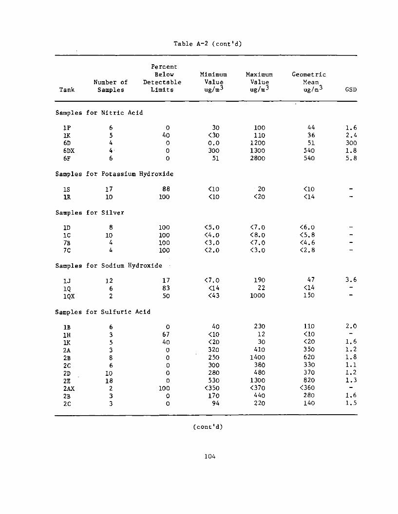
Table A-2 (cont'd)
Percent Below Minimum Maximum Geometric
Number of Detectable Value Value Mean Tank Samples Limits ug/m 3 ug/m3 ug/m3 GSD
Samples for Nitric Acid
lP 6 0 30 100 44 1.6 lK 5 40 00 110 36 2.4 6D 4 0 0.0 1200 51 300 6DX 4 0 300 1300 540 1.8 6F 6 0 51 2800 540 5.8
Samples for Potassium Hydroxide
IS 17 88 <10 20 <10 1R 10 100 <10 <20 <14
Samples for Silver
lD 8 100 <5.0 <7.0 <6.0 Ie 10 100 <4.0 <8.0 <5.8 7B 4 100 0.0 <7.0 <4.6 7C 4 100 <2.0 0.0 <2.8
Samples for Sodium Hydroxide
1J 12 17 <7.0 190 47 3.6 lQ 6 83 <14 22 <14 1QX 2 50 <43 1000 150
Samples for Sulfuric Acid
lB 6 0 40 230 110 2.0 1H 3 67 <10 12 (10 1K 5 40 <20 30 <20 1.6 2A 3 0 320 410 350 1.2 2B 8 0 250 1400 620 1.8 2C 6 0 300 380 330 1.1 2D 10 0 280 480 370 1.2 2E 18 0 530 1300 820 1.3 2AX 2 100 050 070 <360 2B 3 0 170 440 280 1.6 2C 3 0 94 220 140 1.5
(cont'd)
104
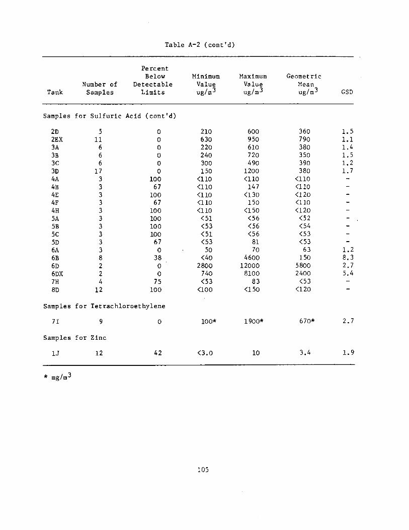
Table A-2 (cont'd)
Percent Below Minimum Maximum Geometric
Number of Detectable Value Value Mean Tank Samples Limits ug/m 3 ug/m 3 ug/m3 GSD
Samples for Sulfuric Acid (cont'd)
2D 5 0 210 600 360 1.5 2EX 11 0 630 950 790 1.1 3A 6 0 220 610 380 1.4 3B 6 0 240 720 350 1.5 3C 6 0 300 490 390 1.2 3D 17 0 150 1200 380 1.7 4A 3 100 <110 <110 <110 4B 3 67 <110 147 <110 4E 3 100 <110 <130 <120 4F 3 67 <110 150 <110 4H 3 100 <110 <150 <120 SA 3 100 <51 <56 <52 5B 3 100 <53 <56 <54 5C 3 100 <51 <56 <53 5D 3 67 <53 81 <53 6A 3 0 50 70 63 1.2 6B 8 38 <40 4600 150 8.3 6D 2 0 2800 12000 5800 2.7 6DX 2 0 740 8100 2400 5.4 7H 4 75 <53 83 <53 8D 12 100 <100 <150 <120
Samples for Tetrachloroethylene
71 9 0 100* 1900* 670* 2.7
Samples for Zinc
13 12 42 0.0 10 3.4 1.9
* mg/m3
105
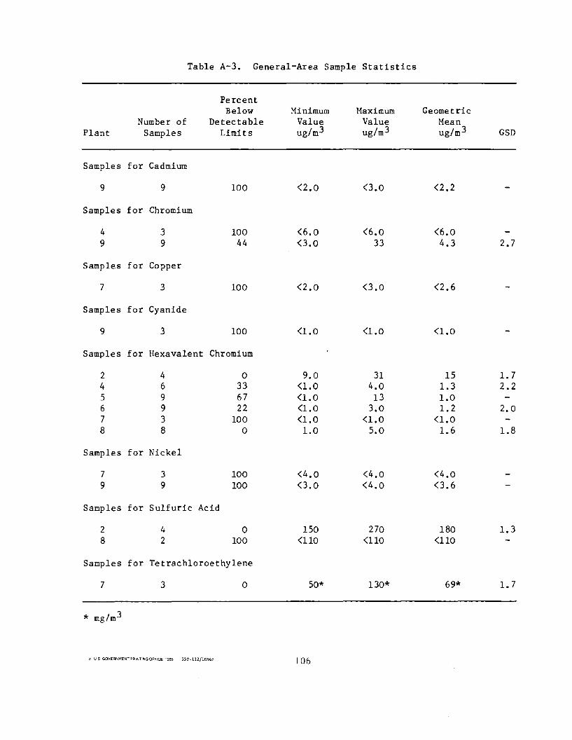
Table A-3. General-Area Sample Statistics
Percent Below Minimum Maximum Geometric
Number of Detectable Value Value Mean Plant Samples Limits ug/m3 ug/m3 ug/m 3 GSD
Samples for Cadmium
9 9 100 <2.0 0.0 <2.2
Samples for Chromium
4 3 100 <6.0 <6.0 <6.0 9 9 44 0.0 33 4.3 2.7
Samples for Copper
7 3 100 <2.0 0.0 <2.6
Samples for Cyanide
9 3 100 <1.0 <1.0 <1.0
Samples for Hexavalent Chromium
2 4 0 9.0 31 15 1.7 4 6 33 <1.0 4.0 1.3 2.2 5 9 67 <1.0 13 1.0 6 9 22 <1.0 3.0 1.2 2.0 7 3 100 <1.0 <1.0 <1.0 8 8 0 1.0 5.0 1.6 1.8
Samples for Nickel
7 3 100 <4.0 <4.0 <4.0 9 9 100 0.0 <4.0 0.6
Samples for Sulfuric Acid
2 4 0 150 270 180 1.3 8 2 100 <110 <110 <110
Samples for Tetrachloroethylene
7 3 0 50* 130* 69* 1.7
* mg/m3
" us GOIIEFlr-.MENT=-FlII\T"NGOFFICE ·~E5 - 559·112/1G9": 106


![[Metalworking] Workshop Practice Series - 11 - Electroplating Metal Anodizing Plating](https://img.dokumen.tips/doc/110x75/577cdcb81a28ab9e78ab3a44/metalworking-workshop-practice-series-11-electroplating-metal-anodizing.jpg)