Embed Size (px)
Citation preview

Control and Optimisation of Cement Quality with Laser
Diffraction Particle Size Analysis and Dry Dispersion
Dr.-Ing. Ulrich Kesten
Sympatec GmbH, D-38678 Clausthal-Zellerfeld, Germany
Copyright© 1997, Sympatec GmbH, D-38678 Clausthal-Zellerfeld, Germany page 1

1 Introduction
Improvement and guarantee of product quality on highest level have become one of the
important issues for industrial production in general and on a global scale.
In the production of cement, the particle size distribution of the final products is one of
the important parameters for quality, as its guarantees for example the final strength of
the concrete. However, the particle size distribution is not only important for the product
quality, it can also be used to characterise the efficiency of the production devices such
as the cement mills and the classifiers. Optimisation of operation cannot only help to
improve product quality it also has an important impact on the economical aspect of
cement production. If due to immediate control of the milling and classifying circuits the
amount of the re-circulated coarse fraction can be decreased by only few percents, the
yield increases and the cost for energy per ton cement decreases remarkably.
Fortunately today the particle size distribution of cement can easily and reliably be
determined.
With the introduction of the first laser diffraction instruments some 25 years ago, the
basis for industrial particle size analysis and production control was laid.
The first generation of laser diffraction particle size analysers was presented in the early
1970’s. It had been developed in close co-operation with the French cement industry and
it was applied exclusively with suspension dispersion, i.e. as wet liquid systems.
In 1984 a new generation of laser diffraction analysers was introduced. It is based on the
simple idea that the instruments used for the characterisation of quality parameters have
to adapt to the products and processes and not vice versa, i.e. that the products have to
adapt to the instruments. This was the established way of how analytical equipment was
designed.
Dry powders should be dispersed dry, wet products and suspensions should be dispersed
in the wet state. This is the practical and consequent conclusion, and the new idea
consequently led to the development of a range of laser diffraction analysers and
dispersing systems that are of modular design thus being easily adaptable to a wide
variety of different products and processes.
Sympatec GmbH from Germany have developed a to date unique instrument for the dry
dispersion of powders in the particle size range from 0.1 µm to nearly 10 mm. This
Copyright© 1997, Sympatec GmbH, D-38678 Clausthal-Zellerfeld, Germany page 2

patented instrument, the RODOS, allows for a smooth, complete and product adaptable
dispersion of all kinds of dry powders.
In combination with the laser diffraction instrument, HELOS, a powerful system for
industrial particle size analysis of the powders is available.
Copyright© 1997, Sympatec GmbH, D-38678 Clausthal-Zellerfeld, Germany page 3

2 Laser Diffraction Principle
The history of Laser Diffraction as an advanced optical analysis principle for fast
determination of particle size distributions in a wide size range, i.e. from 0.1 to x.000 µm,
begins in the early 19th century with the experimental work of Mr. Fraunhofer in Munich
(table 1) [1].
Elements Definition Year
Theory Fraunhofer diffraction physics 1840
Method He-Ne-laser as high energy, coherent light for the generation of particle-light interaction
1960
Sensor multi-element semiconductor first used as aiming device for military application
1965
Processing high performance microcomputers 1970
Result particle size analysis with laser diffraction
since 1972
table 1: History of Laser Diffraction
Those experiments are the basis of what is today known as Fraunhofer diffraction
physics.
From these first experiments it took about 130 years for the technical realisation of the
first laser diffraction particle size analyser in 1972 [2].
The optical set-up for the generation of diffraction patterns (fig. 1) consists of a laser as
light source, an optical beam expander that widens the very fine laser beam to more than
20 mm in diameter, and a measuring zone where the sample is introduced and taken out.
Copyright© 1997, Sympatec GmbH, D-38678 Clausthal-Zellerfeld, Germany page 4

beam expander lens detector
measuring zone
sample in
sample out
laser
fig. 1: optical set up for the generation of diffraction patterns
The measuring zone is the position where the interactions between the monochromatic,
coherent light and the particles take place and the diffraction patterns are generated.
fig. 2: multi-element detector and AUTO-FOCUS unit
Copyright© 1997, Sympatec GmbH, D-38678 Clausthal-Zellerfeld, Germany page 5

These phenomena of intensity distribution of diffracted light are focused on the surface
of an optical detector with the help of a Fourier transformation lens of a distinctive focal
distance. The detector usually consists of up to 31 semicircular elements. They are
transforming the optical light intensity into the corresponding electric current (fig. 2).
A mathematical relationship was established between the diameter of the particles and
the intensity patterns [3]. For a particle size distribution, consisting of fine, intermediate
and coarse particles, the diffraction pattern monitored with the detector incorporates a
two-parameter information; it is the distribution of particle sizes and the quantities in
which the different particle classes contribute to the distribution.
Amongst other elements of the laser diffraction sensor, such as the mechanical stability,
the optical components and the electronics of highest quality, an extremely important
feature that determines the quality of the measurement to a very large extent is the
accurate alignment of the optical set-up. The precise focusing of the central laser beam to
the centre of the detector determines the quality and long-term stability of the
measurements. Sympatec have realised a focusing system, which automatically and
continuously checks this alignment and, if necessary, corrects it before a measurement
can be released (fig. 2).
Copyright© 1997, Sympatec GmbH, D-38678 Clausthal-Zellerfeld, Germany page 6

3 Laser Diffraction Systems and Dispersing Units
As a result of the idea of adaptation of the instruments to the products and processes a
completely modular series of instruments is now available and it comprises instruments
for off-, at-, on-line and in-line particle size analysis with laser diffraction.
The Laser Diffraction Sensor HELOS is the central unit of the analytical system. It
comprises the laser light source, the different Fourier lenses, the multi-element detector
and the system computer for control of the central unit and the evaluation of the particle
size distribution data. Today it covers a size range between 0.1 µm and 8750 µm.
Dispersers are the instruments that are preparing the sample for presentation to the laser
beam of the central unit. The sensor will see the particles as they are presented, i.e.
agglomerates of fine particles will be measured as big particles. Hence the disperser must
guarantee a complete and proper dispersion of the agglomerates down to the primary
particle size. If a dry powder has to be analysed, a dry powder disperser is the best
choice, if a wet product, a suspension, or an emulsion has to be analysed, a suspension or
wet dispersing system is necessary. Approximately 40000 different disperse matters are
being produced in worldwide industry. As a consequence appropriate dispersers for dry
and wet products have to be provided and must be combined with the laser sensor.
As for cement the dry dispersion is the ultimate objective, a closer look to the dry powder
disperser RODOS [4], will be useful.
Due to its two-stage design RODOS can be used with powders in a very wide size range
from below 0.1 µm to more than 8 mm (fig. 3).
Depending on the dispersion characteristics of the powders, different adapters are
applied to feed the sample to the gas-solids injector, being the centrepiece of the
disperser.
For very fine and adhesive powders the sample is fed in surplus into a rotary groove with
the help of a vibratory feeder. Additional scrapers and rollers are compacting the powder
in the groove. Thus a homogeneous mass flow of powder is presented to the rear end of
the disperser. The gas-solids injector is driven by compressed air. In a nozzle it is
accelerated to a velocity of about 50 m/s.
Copyright© 1997, Sympatec GmbH, D-38678 Clausthal-Zellerfeld, Germany page 7

fig. 3: dry dispersing system RODOS
Due to the acceleration of the compressed air, a vacuum is produced at the rear end of
the disperser and the previously homogenised powder is taken into the disperser. In a
zone of steep velocity gradient between the air and the agglomerated particles, shear
forces are applied to destroy these particle aggregates. Additional particle-to-wall and
particle-particle collisions and centrifugal forces generated by the rotation of such
aggregates completely and smoothly take the agglomerates apart, down to the primary
particle sizes.
The powder leaves the disperser as an aerosol in a free jet and crosses the laser beam of
the HELOS instrument at a very short distance from the exit of the disperser. After
passage of the laser beam the aerosol is completely taken out of the air with the help of
an extraction nozzle and a vacuum cleaner.
The advantages of the dry dispersion with RODOS over suspension (wet) dispersion are
manifold and include complete and proper product specific dispersion, adaptable
dispersing forces and variable sample size, highest measurement frequency available to
date, as well as a guaranteed long life time of the disperser with minimum operating costs
(table 2).
Copyright© 1997, Sympatec GmbH, D-38678 Clausthal-Zellerfeld, Germany page 8

H complete and proper dispersion of all dry powders from 0.1 µm
sensitive to changes also in the fine particle range (< 10 µm)
H adjustable dispersing forces
best adaptation to dispensability of different products
H variable sample size
minimising the statistical sampling error
H high measurement frequency due to short cycle time
no cleaning, no rinsing, of sample container
H no chemical interaction between particles and dispersing fluid
no dissolution, no surface reaction, ...
H no reprocessing of contaminated liquid
(e. g. alcohol filtration)
H guaranteed long lifetime of disperser
low operating cost
Í maximum up time
table 2: ADVANTAGES of dry dispersion with RODOS
With regard to application in the cement industry RODOS is the natural way for the
dispersion of
• cement
• raw meal
• coal dust
• fly ash
• ........
Copyright© 1997, Sympatec GmbH, D-38678 Clausthal-Zellerfeld, Germany page 9

4 Automation of Industrial Particle Size Analysis
In addition to the off-line instruments designed for application in labs of all branches with
manually operated dispersing systems, Sympatec have created a new line of instruments,
called at-line, for application in automatic laboratories for continuous quality control.
These instruments automatically perform a particle size analysis once a sample has been
filled into the disperser. They can be operated as stand alone solutions and, due to their
ability to co-operation with robots and central process control systems, they can be
integrated into the laboratory automation systems supplied by well-known plant
manufacturers.
A typical cycle time for a measurement with an integrated auto-line system with the
automatic dry dispersing unit auto-RODOS module totals to less than two minutes (table
3).
step action auto-RODOS auto-SUCELL
1 information input 5“ 5“
2 initialisation 10“ 10“
3 fill-in sample 15“ 60“
4 dispersing & sampling 10“ - 30“ 10“ - 30“
5 sample take-out 15“ - 35“ 60“ - 120“
6 data evaluation 5“ 5“
7 information out 5“ - 60“ 5“ - 60“
Σ 1. - 7.: [minutes] < 2 5
8 stand-by mode 1“ - ∞ 1“ - ∞
table 3: operation modes and cycle times for automatic dispersers
Included in the cycle is the information exchange between the central control computer
of the automatic lab and the HELOS system computer, the fill in of the sample, the
dispersion and measurement of the size distribution, the evaluation of data and transfer
to the host computer [5].
Copyright© 1997, Sympatec GmbH, D-38678 Clausthal-Zellerfeld, Germany page 10

For all those applications where not only the size distribution of cement has to be
controlled but also those of the raw meals, the coal dust for the heating of the furnaces
and the fly ashes as additive to the cement, a fully automatic version of the HELOS
central unit allows for automatic change of the measuring range (auto-ranging).
It means that the size distribution of an extremely fine cement quality can be analysed on
the same instrument as a relatively coarse and broadly distributed raw meal without any
operator touching the instrument. In case the at-line instrument is integrated into an
automated central laboratory, the host computer of the automatic lab announces for
example the different types of products to the HELOS system computer and this will
initialise the central unit to change the measuring range by selection of the appropriate
lens and relocation of the detector unit to the related position on the optical bench; after
auto-focusing the system will run the sample and determine the particle size distribution
with the measuring range that fits the products in the optimum way.
keyboard locking lens cleaningnozzles electronic
boxpneumatic box
extractionpipe
foldable cover
control panelbelt feeder withrotating funnel
fig. 4: auto-RODOS module for automatic particle size analysis
Two typical realisations of automatic cement laboratory systems are shown in the photos
(fig. 5 and 6). One solution is based on a single robot, being centrally installed in the lab
and serving the different analytical equipment sequentially, the other disposes of
different cabinets with one small robot being dedicated to the service of one or several
analytical instruments at a time.
Copyright© 1997, Sympatec GmbH, D-38678 Clausthal-Zellerfeld, Germany page 11

5 Cement Applications
Since 1986 a remarkable number of HELOS systems have been installed in the cement
industry world wide. All of them are equipped with a RODOS dry dispersing unit. 65 %
are operated off-line in the manual mode and 45 %, with quickly increasing trend, are
operated in the automatic version as part of automatic cement laboratories.
As typical results for particle size distributions of products in the cement industry the
differential distribution curves q3lg
of Portland cement in the PZ 35, 45, 55 qualities
analysed
fig. 5: HELOS and auto-RODOS installations in an automatic cement Lab: ROBOLAB of F.L. Smidth, Copenhagen
Copyright© 1997, Sympatec GmbH, D-38678 Clausthal-Zellerfeld, Germany page 12

fig. 6: HELOS and auto-RODOS installations in an automatic cement Lab: POLAB, Krupp-Polysius, Neubeckum)
with HELOS and auto-RODOS module, are plotted on a logarithmically subdivided
abscissa (fig. 7). The presentation is in accordance with the ISO 9276-1 standard. The
distribution curves show the typical multi-modal shape of cement with expressed fine
tails.
The ability of the RODOS dry disperser to even properly dispersing the extremely fine
powders of the new generation of Micro-Cements is proven by the next graph (fig. 8). The
cumulative distribution curves by volume Q3 and the corresponding differential
distributions curves q3lg of three ultra-fine cements show that these qualities contain
more than 20 to 30 % of particles below one micrometer and a maximum particle size of
only 20-30 microns.
Copyright© 1997, Sympatec GmbH, D-38678 Clausthal-Zellerfeld, Germany page 13

0
10
20
30
40
diffe
rent
ial d
istr
ibut
ion
q3l
g
1E-1 1E0 1E1 1E2 1E3particle diameter x / µm
portland cement PZ35 portland cement PZ45 portland cement PZ55
dry dispersionwith
auto-RODOS-module
SYMPATECGermany
3E10K29U3E
automaticParticle Size Analysis
withHELOS
fig. 7: typical particle size distributions of Portland cements
C1
C3
-110 010 110 2100
20
40
60
80
100
x microns
PC
T un
der c
umul
ativ
e Q
3
HRLD: Volume distributions of fine cements
0
7.5
15
22.5
30
37.5D
istri
butio
n de
nsity
q3l
g
C2
fig. 8: RODOS: dry dispersion of ULTRA-FINE (SUBMICRON) micro-cements
Copyright© 1997, Sympatec GmbH, D-38678 Clausthal-Zellerfeld, Germany page 14
0
10
20
30
40
diffe
rent
ial d
istr
ibut
ion
q3l
g
1E-1 1E0 1E1 1E2 1E3particle diameter x / µm
coal dust fly ash raw meal3E10K29U4E
automaticParticle Size Analysis
withHELOS
dry dispersionwith
auto-RODOS-module
SYMPATECGermany
fig. 9: particle size distributions of raw meal, fly ash, coal dust
In an additional graph the results of the analysis of raw meal, coal dust and fly ash are
shown. Of special interest is the extremely broad distribution of raw meal with a manifold
of modes in the differential curve that might be related to the numerous components of
raw meal (fig. 9).
The extreme long time stability of the auto-RODOS module as operated with the HELOS
laser diffraction instrument is illustrated in fig. 10.
The standard deviation over the lifetime is less than 1 % or expressed in terms of the
BLAINE surface, inferior to +/- 40 cm²/g for 4000 cm²/g (fig. 10). With regard to the
long time stability of the dispersing line of the auto-RODOS instrument, Sympatec
guarantees a life time of minimum 25.000 measurements of PZ 35 F, i.e. a life time of
typically far more than one year in an automatic production control laboratory.
Compared to the operating cost of systems that are using suspension dispersion in
alcohol, the dry dispersing system RODOS has an advantage of probably more than 50%.
Copyright© 1997, Sympatec GmbH, D-38678 Clausthal-Zellerfeld, Germany page 15

5000
4900
4800
4700
4600
4500
0
-2%
-4%
-6%
1 2500 5000 7500 10000 12500 15000 17500 20000
5000
100015002000250030003500400045005000
60005500
number of samples PZ35F, 10g each
Blaine
Blaine ∆
HELOS and auto-RODOS
factory customer
Blaine-values Sf q
xxM
iii= ∑6 3
ρ∆
fine fraction <10 µm is significant for the specific surface !!
standard deviation: < 1%, typical 0,4% Blaine values: ± 40 cm²/g for 4000 cm²/g lifetime: ca. 250 kg PZ 35 F, i.e. >25.000 samples, 10 g each,
or typical 1 year in 24h continuous operation
fig.10: guaranteed long-time stability of RODOS and HELOS measurements
Copyright© 1997, Sympatec GmbH, D-38678 Clausthal-Zellerfeld, Germany page 16

6 Process Optimisation
Optimisation of operation of unit operations with particles can not only help to improve
product quality it also has an important impact on the economical aspect of cement
production. If due to immediate control of the milling and classifying circuits the amount
of the re-circulated coarse fraction can be decreased by only few per cent, the yield
increases and the cost for energy per ton cement decreases remarkably.
For the characterisation of the efficiency of mills and classifiers the Grade Efficiency or
Tromp curve has been used successfully.
From the complete mass balance of feed material into the unit operation, e.g. the
classifier, the fines (product) and the coarse (re-circulated material) and the particle size
distributions of at least two of the components, the Tromp curve T(x) can be determined
according to the following equation:
C . qc(x)
T(x) = qf (x)
T(x) represents the ratio of the relative amount of material of a certain size, present in the
coarse material (oversize, reject) (cqc(x)dx), to the relative amount of the same size
initially present in the feed material (qf(x)dx).
C = relative amount of coarse material
Mc M'c
C = = Mf M'f
Mf, M'f = amount, mass flow rate of feed material
Mc , M'c = amount, mass flow rate of coarse material
Fig. 11 represents the Tromp Curve T(x) as determined from the particle size
distributions of the Feed, the Coarse and the Fines of a separation or classification
process.
Copyright© 1997, Sympatec GmbH, D-38678 Clausthal-Zellerfeld, Germany page 17

And with fig. 12 an explanation and discussion of a typical course of a Tromp curve is
given.
An ideal separation would be such that for a desired and set separation diameter xt the
fines would not contain any amount of course particles and the coarse would not contain
any amount of fine particles. Hence the Tromp curve T(x) would be a straight line parallel
to the ordinate of the Tromp curve graph. In reality Tromp curves have an S-shaped
course with a gradient becoming steeper with a better operation of the classifier. Very
often we find the Tromp curve not even ending at the bottom line of the abscissa but also
moving upwards again in the fines.
The distance from the minimum of T(x) to the bottom line of the abscissa is referred to as
τ. It represents the amount of feed material that is passing through the classifier without
separation. This is often due to an overload of the separator.
The increase of the Tromp curve in the fine particle range refers to the amount of fine
particles in the coarse fraction. This is usually due to the fact that the classifiers are fed
with incompletely dispersed powder. The agglomerates hence are taken as coarse
particles and during the particle size analysis with properly operating dispersers they are
detected as the fine particles they have been in reality.
Potentials for the optimisation of the classification process are to be found in the
improvement of the dispersion of the feed material before it enters the classifier zone.
The resulting reduction of the amount of fines in the coarse fraction decreases the re-
circulated mass flow into the mills. This decreases the energy consumption per ton of
product remarkably. In addition the amount of the fine (product) fraction increases, and
hence the yield of the process is much better. Already the improvement of this detail in
the large number of parameters affecting the process of cement manufacturing has a dual
positive effect. It can be achieved with the control of the particle size distribution using
the laser diffraction principle and the dry dispersion.
Copyright© 1997, Sympatec GmbH, D-38678 Clausthal-Zellerfeld, Germany page 18

fig. 11: characterisation of classification process with TROMP curve
fig. 12: typical course of a TROMP curve of a real classification process
Copyright© 1997, Sympatec GmbH, D-38678 Clausthal-Zellerfeld, Germany page 19
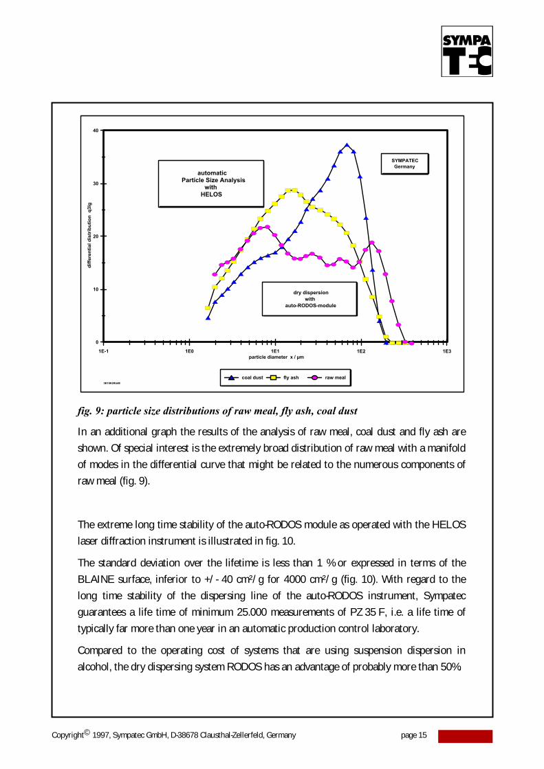
7 References
[1] J. Fraunhofer Bestimmung des Brechungs- und Farbzerstreuungsvermögens
verschiedener Glasarten
Gilberts Annalen der Physik, 56 (1817) 193-226
[2] Stephan Röthele, Ulrich Kesten:
The Application of Laser Diffraction Technology,
2nd World Congress of Particle Technology 1990,
19. - 22. September 1990, Kyoto, Japan
[3] Michael Heuer, Kurt Leschonski: Results Obtained with a New Instrument for the Measurement
of Particle Size Distributions from Diffraction Patterns,
Part. Charact. 2 (1985) 7 - 13
[4] Kurt Leschonski, Stephan Röthele, Ulrich Menzel: A Special Feeder for Diffraction Pattern Analysis
of Dry Powders,
Part. Charact. 1 (1984) 161 - 166
[5] Stephan Röthele, Heinz Naumann, Udo Brandis:
on-line Sampling and Sample Splitting -
Principle and Instrumentation
6th Conference Granulometry, 21. - 22. Nov. 1989, Dresden
[6] Kurt Leschonski Representation and Evaluation of Particle Size Analysis Data
Particle Characterisation 1 (1984), 89 - 95
Copyright© 1997, Sympatec GmbH, D-38678 Clausthal-Zellerfeld, Germany page 20