Embed Size (px)
Citation preview

Control allocation for a high-precision linear transport system
R. Beerens1, S.C.N. Thissen2, A. van der Maas2, W.C.M. Pancras3,T.M.P. Gommans4, N. van de Wouw1,5, W.P.M.H. Heemels1
Abstract— We present a control allocation framework toimprove the performance of an industrial translational trans-port and positioning system, based on an inverted permanent-magnet linear synchronous motor. Compared to the state-of-practice control solution, the proposed allocation techniqueachieves enhanced tracking, improved motion freedom, andrelaxed hardware design specifications.
I. INTRODUCTION
In this paper, we present a control allocation frameworkto improve the performance of industrial high-precisiontransport and positioning systems, see Fig. 1. In particu-lar, we consider linear (i.e., translational) motion systems,where multiple carriers can move on horizontal tracks, usingthe inverted permanent-magnet linear synchronous motor(IPMLSM) actuation principle, see, e.g., [1]. Here, the coilsof the three-phase actuators are located on the tracks and themagnets on the carriers, see Fig. 1, such that the movingcarriers do not have any electronics or cables attachedto them. This principle makes the system highly suitableto be used in automated production lines consisting of,e.g., operation in vacuum, high temperature, or chemicalenvironments. Due to these characteristics, such systemsare widely used in industry in, e.g., the production of flatscreens, OLED lighting, and solar cells, see, e.g., [2]. Thedifferent operations that are executed on the products alongthe production line, requires the system to allow for flexible,and independent motion of each carrier along the track.
IPMLSM-based motion systems are typically over-actuated, since a carrier may commute with more thanone set of coils in the track at the same time (i.e., onecarrier is actuated by multiple actuators simultaneously),or multiple carriers may be influenced by the same set ofcoils (actuator) simultaneously. This may lead to conflictingcontrol objectives, and may result in large position errors or
?This research is part of the research programme High Tech Systemsand Materials (HTSM), which is supported by NWO domain Applied andEngineering Sciences and partly funded by the Dutch Ministry of EconomicAffairs.
1R. Beerens, N. van de Wouw, and M. Heemels are with the Dept.of Mechanical Engineering, Eindhoven University of Technology, P.O.Box 513, 5600MB Eindhoven, the Netherlands, {r.beerens; n.v.d.wouw;w.p.m.h.heemels}@tue.nl
2S. Thissen and A. van der Maas are with ASML, DeRun 6501, 5504DR, Veldhoven, the Netherlands, {stijn.thissen;annemiek.vandermaas}@asml.com.
3W. Pancras is with Fontys University of Applied Sciences, Dept.of Mechatronics, P.O. Box 347, 5600AH Eindhoven, the Netherlands,[email protected]
4T. Gommans is with Microsure, Science Park 5080, 5692EA Son,[email protected]
5N. van de Wouw is also with the Department of Civil, Environmentaland GeoEngineering, Univ. of Minnesota, USA, and with the Delft Centerfor Systems and Control, the Netherlands.
Fig. 1. Industrial IPMLSM-based transport and positioning system. Thecarriers are indicated in blue, and the actuators in red.
the inability to control carriers independently when usingstate-of-practice control solutions. Moreover, the actuatorcharacteristics suffer from position dependency and end-effects (to be discussed in more detail in Section II), whichpose design limitations in the sense that actuators must beplaced at specific locations on the tracks. In this work, weaim to overcome the above limitations by means of intelligent(allocation-based) control.
IPMLSM-based transport systems are often controlled us-ing Field Oriented Control, see, e.g., [3], [4], where actuatorredundancy is often handled through the use of commutationalgorithms [1], [5]. These algorithms aim to find a linearcombination of all control inputs acting on a carrier, such thatonly a force in the direction of motion is generated. However,these existing commutation algorithms cannot handle inde-pendent control of multiple carriers simultaneously. Othercontrol techniques that can handle actuator redundancy are,e.g., optimal control (see, e.g., [6], [7]) or control allocation(see, e.g., [7], [8]). Well-known examples of the former arelinear quadratic control [6, Ch. 15], [9], H∞ control [6,Ch. 16-18], or model predictive control [10].
For the current application, however, control allocationtechniques offer several benefits over other techniques: itmay invoke less computational efforts compared to optimalcontrol techniques [7], and separates controller tuning fromthe distribution of the resulting control efforts. In this way,well-known loop-shaping techniques often used in industryfor the tuning of motion controllers can still be applied.
In this paper we present a control allocation frameworkfor an IPMLSM-based transport and positioning system thatachieves 1) increased tracking performance compared toindustrial, state-of-practice control solutions, 2) independentmotion of carriers, and 3) a relaxation of hardware designrestrictions. The remainder of this paper is organized as fol-lows. In Section II, we provide a detailed system description,and the proposed control allocation architecture is discussedin Section III. We illustrate the achievable performance
2018 IEEE Conference on Decision and Control (CDC)Miami Beach, FL, USA, Dec. 17-19, 2018
978-1-5386-1394-8/18/$31.00 ©2018 IEEE 1657
benefits of the proposed controller by a simulation study inSection IV, and provide conclusions in Section V.
II. SYSTEM DESCRIPTION
This section starts with the basic actuation principle of anIPMLSM, followed by a model of the considered transportsystem.
A. Actuation principle
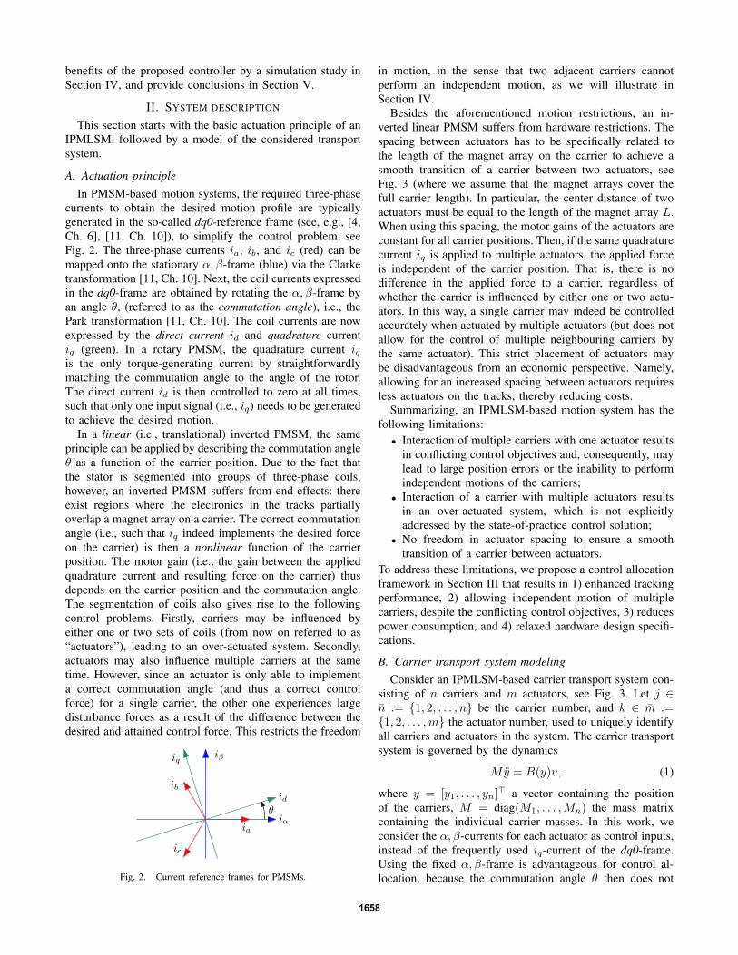
In PMSM-based motion systems, the required three-phasecurrents to obtain the desired motion profile are typicallygenerated in the so-called dq0-reference frame (see, e.g., [4,Ch. 6], [11, Ch. 10]), to simplify the control problem, seeFig. 2. The three-phase currents ia, ib, and ic (red) can bemapped onto the stationary α, β-frame (blue) via the Clarketransformation [11, Ch. 10]. Next, the coil currents expressedin the dq0-frame are obtained by rotating the α, β-frame byan angle θ, (referred to as the commutation angle), i.e., thePark transformation [11, Ch. 10]. The coil currents are nowexpressed by the direct current id and quadrature currentiq (green). In a rotary PMSM, the quadrature current iqis the only torque-generating current by straightforwardlymatching the commutation angle to the angle of the rotor.The direct current id is then controlled to zero at all times,such that only one input signal (i.e., iq) needs to be generatedto achieve the desired motion.
In a linear (i.e., translational) inverted PMSM, the sameprinciple can be applied by describing the commutation angleθ as a function of the carrier position. Due to the fact thatthe stator is segmented into groups of three-phase coils,however, an inverted PMSM suffers from end-effects: thereexist regions where the electronics in the tracks partiallyoverlap a magnet array on a carrier. The correct commutationangle (i.e., such that iq indeed implements the desired forceon the carrier) is then a nonlinear function of the carrierposition. The motor gain (i.e., the gain between the appliedquadrature current and resulting force on the carrier) thusdepends on the carrier position and the commutation angle.The segmentation of coils also gives rise to the followingcontrol problems. Firstly, carriers may be influenced byeither one or two sets of coils (from now on referred to as“actuators”), leading to an over-actuated system. Secondly,actuators may also influence multiple carriers at the sametime. However, since an actuator is only able to implementa correct commutation angle (and thus a correct controlforce) for a single carrier, the other one experiences largedisturbance forces as a result of the difference between thedesired and attained control force. This restricts the freedom
θiα
id
iβiq
ib
ic
ia
Fig. 2. Current reference frames for PMSMs.
in motion, in the sense that two adjacent carriers cannotperform an independent motion, as we will illustrate inSection IV.
Besides the aforementioned motion restrictions, an in-verted linear PMSM suffers from hardware restrictions. Thespacing between actuators has to be specifically related tothe length of the magnet array on the carrier to achieve asmooth transition of a carrier between two actuators, seeFig. 3 (where we assume that the magnet arrays cover thefull carrier length). In particular, the center distance of twoactuators must be equal to the length of the magnet array L.When using this spacing, the motor gains of the actuators areconstant for all carrier positions. Then, if the same quadraturecurrent iq is applied to multiple actuators, the applied forceis independent of the carrier position. That is, there is nodifference in the applied force to a carrier, regardless ofwhether the carrier is influenced by either one or two actu-ators. In this way, a single carrier may indeed be controlledaccurately when actuated by multiple actuators (but does notallow for the control of multiple neighbouring carriers bythe same actuator). This strict placement of actuators maybe disadvantageous from an economic perspective. Namely,allowing for an increased spacing between actuators requiresless actuators on the tracks, thereby reducing costs.
Summarizing, an IPMLSM-based motion system has thefollowing limitations:• Interaction of multiple carriers with one actuator results
in conflicting control objectives and, consequently, maylead to large position errors or the inability to performindependent motions of the carriers;
• Interaction of a carrier with multiple actuators resultsin an over-actuated system, which is not explicitlyaddressed by the state-of-practice control solution;
• No freedom in actuator spacing to ensure a smoothtransition of a carrier between actuators.
To address these limitations, we propose a control allocationframework in Section III that results in 1) enhanced trackingperformance, 2) allowing independent motion of multiplecarriers, despite the conflicting control objectives, 3) reducespower consumption, and 4) relaxed hardware design specifi-cations.
B. Carrier transport system modelingConsider an IPMLSM-based carrier transport system con-
sisting of n carriers and m actuators, see Fig. 3. Let j ∈n := {1, 2, . . . , n} be the carrier number, and k ∈ m :={1, 2, . . . ,m} the actuator number, used to uniquely identifyall carriers and actuators in the system. The carrier transportsystem is governed by the dynamics
My = B(y)u, (1)
where y = [y1, . . . , yn]> a vector containing the positionof the carriers, M = diag(M1, . . . ,Mn) the mass matrixcontaining the individual carrier masses. In this work, weconsider the α, β-currents for each actuator as control inputs,instead of the frequently used iq-current of the dq0-frame.Using the fixed α, β-frame is advantageous for control al-location, because the commutation angle θ then does not
1658

j = 1 2 3 4 5
k = 1 2 3 4 5 6 7 8
L
y1 y2 y3 y4 y5
Fig. 3. Schematic representation of the IPMLSM-based transport system.Arrows denote the influence of an actuator (index k) on a carrier (index j),and arrows marked in red influence two carriers. .
appear in the motor gain matrix B(y) in (3) below. This isan instrumental observation for the proposed control solution(see also Remark 2 below). The input vector u is then givenby
u = [iα,1, iβ,1, . . . , iα,m, iβ,m]>. (2)
Due to the position dependency of the commutation betweenthe carriers and the coils, the motor gain matrix B(y) is givenby
B(y) =
bα11(y1) bβ11(y1) . . . bα1m(y1) bβ1m(y1)
......
. . ....
...bαn1(yn) bβn1(yn) . . . bαnm(yn) bβnm(yn)
,(3)
where bαjk and bβjk are actuator-specific, position-dependentmotor gains. The right-hand side of (1) then results in acolumn with forces applied on the carriers, i.e.,
τ = B(y)u =
[m∑k=1
τ1k . . .m∑k=1
τnk
]>. (4)
In (4), τjk is the force applied by actuator k on carrier j,and is straightforwardly given by
τjk = bαjk(yj)iα,k + bβjk(yj)iβ,k. (5)
Note that some elements τjk in (4) may be zero if actuatork does not influence carrier j, which is the case whenthe carrier is not close enough to the actuator in order tocommute.
Let us introduce the relative position of carrier j withrespect to actuator k:
zjk := yj − Yk, (6)
where Yk is the position of actuator k on the tracks, de-fined as the minimum position yj , where actuator k startsinfluencing a carrier j, i.e.,
Yk := min{yj | bαjk(yj) 6= 0 ∨ bβjk(yj) 6= 0
}. (7)
Note that (7) is independent of j. We are now ready to posethe following assumption regarding controllability of eachcarrier and similarity of the hardware components.
Assumption 1. Rank(B(y)) = n at all times.
Assumption 2. All three-phase coil segments and permanentmagnet arrays are identical.
As a result of Assumption 1, any carrier at any positionon the tracks is influenced by at least one actuator. Aconsequence of Assumption 2 is that the motor gains ofeach actuator k w.r.t. each carrier j are identical. We can
then simplify the motor gain matrix B in (3) by writing bαjkand bβjk in (3) as
bαjk(yj) = bα(zjk), bβjk(yj) = bβ(zjk). (8)
The motor gains in (8) are typically obtained from FEM-based electromagnetic simulations on the interaction betweena carrier and an actuator, see [1]. By Assumption 2, we onlyhave to perform these simulations for a single actuator/carrierinteraction, simplifying the implementation of the controlallocation architecture below (where the gain matrix B isexplicitly used). Note that Assumption 2 is not necessarilyneeded for the developments in this paper, but leads tosignificantly reduced complexity of B and therefore easierimplementation. The control allocation scheme presented be-low is also applicable in case the actuators are not identical.
III. CONTROL ARCHITECTURE
In this section, the proposed control architecture is pre-sented. We will first discuss the high-level control scheme,and subsequently the allocation algorithm.
A. High-level control schemeAs discussed in Section II-A, the state-of-practice control
solution (which we will elaborate on in more detail in Sec-tion IV-A below) is not able to handle the control of multiplecarriers by one actuator simultaneously, since the correctcommutation angle for only one carrier can be obtained. Wetherefore propose the control allocation scheme below, thatcan cope with multiple carriers instead.
Consider Fig. 4. The error signals e between a referencesignal r (one for each carrier on the track), and the currentcarrier positions y are provided to a motion controller.This controller is typically designed using well-known loop-shaping techniques, and generates the desired control forcesτc = [τc1, . . . , τcn]>. These desired control forces shouldthen be applied to the carriers by the AC actuators. Theprimary objective of the control allocator is thus to find thecurrents iαk and iβk in the control input u in (2), such thatthe actuators indeed implement the desired control forcesgiven by τc. In other words, the actual forces acting on thecarriers, denoted by τ in Fig. 4, should be equal to thedesired control forces coming from the motion controller,i.e., τ = B(y)u = τc. Due to the over-actuated nature ofthe system, the solution to the allocation problem τ = τc (ifattainable by the actuators) is not unique. We will exploitthis freedom to introduce a second control objective, namelythe minimization of power consumption by the actuators.
We will now discuss two allocation procedures: an uncon-strained procedure, and a constrained procedure. The latterincorporates a saturation constraint on the input, which ismotivated by the desire from industry to use cost-effective(less powerful) actuators.
motioncontroller
plantrn×1 en×1 τn×1
c u2m×1 yn×1controlallocation
actuatorelectronics
τn×1
−
Fig. 4. High-level control architecture. The superscripts on the signalsindicate their dimensions.
1659
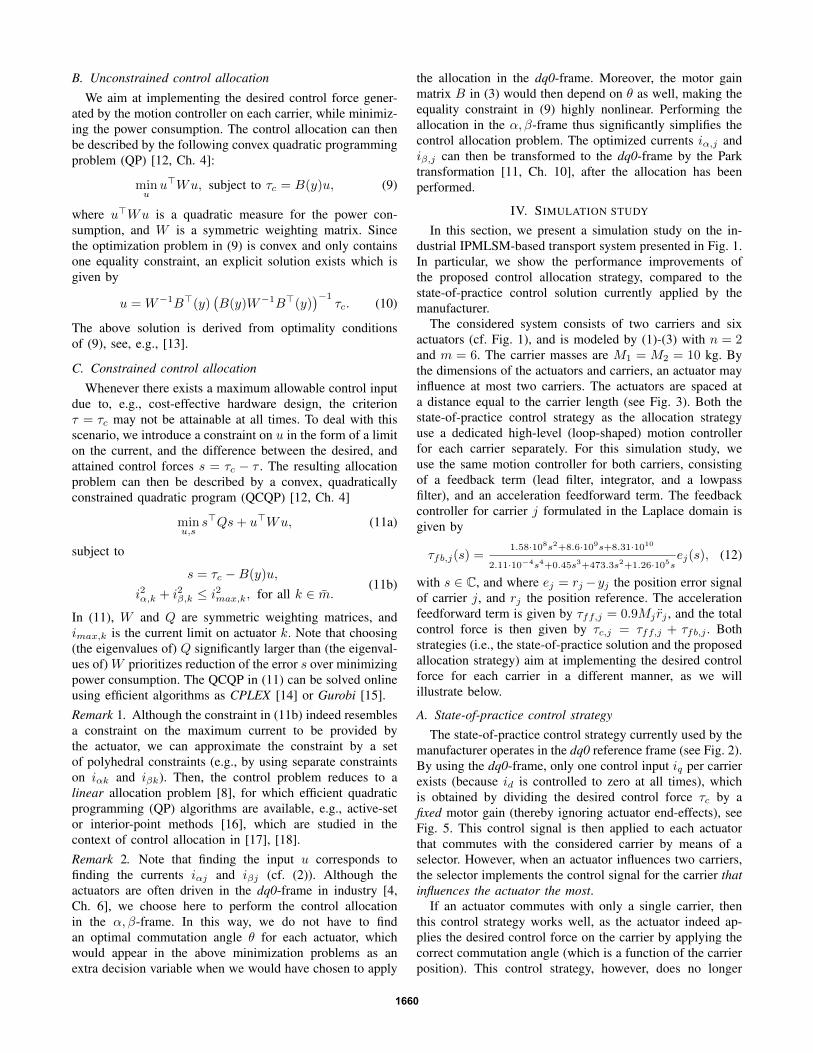
B. Unconstrained control allocation
We aim at implementing the desired control force gener-ated by the motion controller on each carrier, while minimiz-ing the power consumption. The control allocation can thenbe described by the following convex quadratic programmingproblem (QP) [12, Ch. 4]:
minuu>Wu, subject to τc = B(y)u, (9)
where u>Wu is a quadratic measure for the power con-sumption, and W is a symmetric weighting matrix. Sincethe optimization problem in (9) is convex and only containsone equality constraint, an explicit solution exists which isgiven by
u = W−1B>(y)(B(y)W−1B>(y)
)−1τc. (10)
The above solution is derived from optimality conditionsof (9), see, e.g., [13].
C. Constrained control allocation
Whenever there exists a maximum allowable control inputdue to, e.g., cost-effective hardware design, the criterionτ = τc may not be attainable at all times. To deal with thisscenario, we introduce a constraint on u in the form of a limiton the current, and the difference between the desired, andattained control forces s = τc − τ . The resulting allocationproblem can then be described by a convex, quadraticallyconstrained quadratic program (QCQP) [12, Ch. 4]
minu,s
s>Qs+ u>Wu, (11a)
subject to
s = τc −B(y)u,
i2α,k + i2β,k ≤ i2max,k, for all k ∈ m.(11b)
In (11), W and Q are symmetric weighting matrices, andimax,k is the current limit on actuator k. Note that choosing(the eigenvalues of) Q significantly larger than (the eigenval-ues of) W prioritizes reduction of the error s over minimizingpower consumption. The QCQP in (11) can be solved onlineusing efficient algorithms as CPLEX [14] or Gurobi [15].Remark 1. Although the constraint in (11b) indeed resemblesa constraint on the maximum current to be provided bythe actuator, we can approximate the constraint by a setof polyhedral constraints (e.g., by using separate constraintson iαk and iβk). Then, the control problem reduces to alinear allocation problem [8], for which efficient quadraticprogramming (QP) algorithms are available, e.g., active-setor interior-point methods [16], which are studied in thecontext of control allocation in [17], [18].Remark 2. Note that finding the input u corresponds tofinding the currents iαj and iβj (cf. (2)). Although theactuators are often driven in the dq0-frame in industry [4,Ch. 6], we choose here to perform the control allocationin the α, β-frame. In this way, we do not have to findan optimal commutation angle θ for each actuator, whichwould appear in the above minimization problems as anextra decision variable when we would have chosen to apply
the allocation in the dq0-frame. Moreover, the motor gainmatrix B in (3) would then depend on θ as well, making theequality constraint in (9) highly nonlinear. Performing theallocation in the α, β-frame thus significantly simplifies thecontrol allocation problem. The optimized currents iα,j andiβ,j can then be transformed to the dq0-frame by the Parktransformation [11, Ch. 10], after the allocation has beenperformed.
IV. SIMULATION STUDY
In this section, we present a simulation study on the in-dustrial IPMLSM-based transport system presented in Fig. 1.In particular, we show the performance improvements ofthe proposed control allocation strategy, compared to thestate-of-practice control solution currently applied by themanufacturer.
The considered system consists of two carriers and sixactuators (cf. Fig. 1), and is modeled by (1)-(3) with n = 2and m = 6. The carrier masses are M1 = M2 = 10 kg. Bythe dimensions of the actuators and carriers, an actuator mayinfluence at most two carriers. The actuators are spaced ata distance equal to the carrier length (see Fig. 3). Both thestate-of-practice control strategy as the allocation strategyuse a dedicated high-level (loop-shaped) motion controllerfor each carrier separately. For this simulation study, weuse the same motion controller for both carriers, consistingof a feedback term (lead filter, integrator, and a lowpassfilter), and an acceleration feedforward term. The feedbackcontroller for carrier j formulated in the Laplace domain isgiven by
τfb,j(s) =1.58·108s2+8.6·109s+8.31·1010
2.11·10−4s4+0.45s3+473.3s2+1.26·105sej(s), (12)
with s ∈ C, and where ej = rj−yj the position error signalof carrier j, and rj the position reference. The accelerationfeedforward term is given by τff,j = 0.9Mj rj , and the totalcontrol force is then given by τc,j = τff,j + τfb,j . Bothstrategies (i.e., the state-of-practice solution and the proposedallocation strategy) aim at implementing the desired controlforce for each carrier in a different manner, as we willillustrate below.
A. State-of-practice control strategyThe state-of-practice control strategy currently used by the
manufacturer operates in the dq0 reference frame (see Fig. 2).By using the dq0-frame, only one control input iq per carrierexists (because id is controlled to zero at all times), whichis obtained by dividing the desired control force τc by afixed motor gain (thereby ignoring actuator end-effects), seeFig. 5. This control signal is then applied to each actuatorthat commutes with the considered carrier by means of aselector. However, when an actuator influences two carriers,the selector implements the control signal for the carrier thatinfluences the actuator the most.
If an actuator commutes with only a single carrier, thenthis control strategy works well, as the actuator indeed ap-plies the desired control force on the carrier by applying thecorrect commutation angle (which is a function of the carrierposition). This control strategy, however, does no longer
1660

motioncontroller B−1
selector
plant
rn×1 en×1 τn×1c
in×1q
im×1q
yn×1actuatorelectronics
τm×1
−
Fig. 5. State-of-practice control strategy. The superscripts on the signalsindicate their dimensions.
work properly when an actuator influences two carriers. Thecorrect commutation angle is then only applied for the mostoverlapping carrier, which results in a wrong commutationangle for the second carrier. As a result, there is a mismatchbetween the desired and implemented control force on thecarrier that overlaps the actuator the least. The implicationsof this fact are illustrated below.
B. Proposed allocation strategyIn contrast to the state-of-practice control strategy, the
allocation scheme is applied in the α, β reference frame.The coefficients of the position-dependent motor gain matrixB(y) in (3), (8) are obtained from FEM-based electromag-netic simulations [1] by measuring the relative position zjkof carrier j with respect to actuator k. We assume thatall actuators are identical, see Assumption 2. The motorgains, as a function of zjk, are presented in Fig. 6, wherethe deterioration of the gains at both ends of the regionof influence can be observed (i.e., the end-effects). Themotor gain matrix is explicitly used in the allocation scheme,see (9), (10), and (11).
C. Simulation resultsWe have implemented the system model (1)-(3), and
both the state-of-practice and proposed allocation controllerstrategies. The following three scenarios are studied:
a) A parallel motion of the carriers, where the relativedistance between the carriers is equal to an integer timesthe pole-pair pitch of the magnets;
b) A parallel motion of the carriers, with a reduced relativedistance (not equal to an integer times the pole-pairpitch of the magnets);
c) A complex motion, combining independent and adja-cent carrier motion. This reference trajectory has beenrecorded from the setup in Fig. 1 by manually movingthe carriers.
We will now discuss the results for each scenario.
0 0.05 0.1 0.15 0.2 0.25 0.3 0.35 0.4 0.45-30
-20
-10
0
10
20
30
Fig. 6. Motor gains as a function of the relative position.
Scenario a) Consider Fig. 7a. Both carriers track the ref-erence well when controlled by either the state-of-practicestrategy, and the (unconstrained) allocation strategy of Sec-tion III-B. Due to the specific relative distance betweenthe carriers, the actuators are able to sufficiently align forboth carriers and the control force requested by the motioncontroller is achieved well, despite the fact that actuator 2,3, and 4 influence both carriers (see the third subplot). Sinceboth carriers perform the same motion profile, they requirethe same control forces. Then, due to the fact that the relativedistance between the carriers is equal to an integer times thepole-pair pitch of the magnets, the required commutationangle of the actuator is the same. As a result, the controlforces τc are indeed attainable for both carriers so that bothcarriers are able to track the reference. As expected, theproposed control allocation strategy has equal performanceto the state-of-practice control strategy in terms of accuracyin this specific scenario.
Scenario b) Consider Fig. 7b, where the relative distancebetween the carriers have been slightly decreased with re-spect to Scenario a). It stands out that the state-of-practicecontroller now results in a relatively large position errorduring the acceleration phase. This is caused by the factthat the shared actuators are only able to take the correctcommutation angle for the most overlapping carrier. Theother carrier then experiences a control force that deviatesfrom the desired control force coming from the motioncontroller. In contrast, the unconstrained allocation schemeof III-B is instead able to find a control input such that thetrajectory can be followed well, with only small positionerrors. Next, we apply the constrained allocation schemeof III-C to investigate the potential of the controller whenless powerful actuators are used. Less powerful actuatorsyield economic benefits for the manufacturer, if the desiredspecifications in terms of accuracy are still satisfied. We takeW = I2m, Q = 5In (with I the identity matrix), and setseparate current saturation limits for both iαk and iβk to 0.8A (see Remark 1). The results are shown in red-dashed inFig. 7b), where it can be observed that the limited attainablecontrol force yields a local increase in position error (see thesecond subplot), but significantly less actuator duty (see thebottom subplots).
Scenario c) Consider Fig. 7c. The state-of-practice controlsolution is now unable to allow both carriers to follow thereference due to the mismatch in desired and implementedcontrol force, as discussed in Scenario b). It stands out that,due to the independent motion of the carriers, this mismatchis large enough for one carrier to completely deviate fromthe setpoint when using the state-of-practice controller. Theunconstrained allocation scheme of Section III-B results ingood tracking of both carriers instead, with only a smallposition error. The constrained allocation scheme of Sec-tion III-C (with Q and W as in Scenario b), and challengingmaximum values of 0.4A for both iα,k and iβ,k) againresults in decreased tracking performance, but significantlyless actuator duty.
1661

0
0.5
1
1.5
0
2
4
10−5
0 0.5 1 1.50
2
4
6
0 0.2 0.4
−1
0
1
0 0.5 1
−1
0
1
no allocation unconstr. allocationposition[m
]‖e‖ 2
[m]
active
actuator
time [s]
time [s] time [s]
iα iβ
i α,i β
[A]
(a)
0
0.5
1
1.5
0
2
4
10−4
0 0.5 1 1.50
2
4
6
0 0.2 0.4 0.6
−1
0
1
0.2 0.3 0.4 0.5
−1
0
1
no allocation unconstr. constr.
position[m
]‖e‖ 2
[m]
active
actuator
unconstr. constr.
carrier 1 carrier 2
i α[A
]
time [s]
time [s] time [s](b)
0.2
0.4
0.6
0
2
410−3
0 2 4 6 80
2
4
6
0 2 4 6 8−1
0
1
0 2 4 6 8−1
0
0 50
1
10−5
no allocation unconstr. constr.
position[m
]‖e‖ 2
[m]
active
actuator
i α[A
]
carrier 1 carrier 2
time [s]
time [s] time [s]
unconstr. constr.
(c)Fig. 7. Simulation results for the scenarios a, b, and c. From top to bottom: carrier position and (scaled) acceleration setpoint (gray), norm of the positionerror, active actuators, and illustrative input currents. The gray patches in the 3rd subplots indicate the time spans where an actuator influences both carriersfor the unconstrained allocation simulations. The bottom plots show, for actuator 2 and 3, the α, β-currents in (a), and the α-currents in (b) and (c).
D. Discussion
The simulation study shows that the proposed controlallocation scheme achieves (compared to the state-of-practicecontroller used by the manufacturer) 1) improved trackingperformance, 2) allowing independent motion of multiplecarriers while influenced by shared actuators, and 3) the pos-sibility to take account actuator limits into account. The latterresult may be used by the manufacturer to find a trade-off be-tween achievable tracking performance and required actuatorpower: taking into account that less powerful actuators areoften more cost-effective. An advantage of a cost-effectivesystem design also results from the fact that the allocationscheme allows for a less strict actuator spacing. Namely,the control allocation algorithm is able to compensate forfluctuations in the motor gains due to end-effects, by adaptingthe control currents. In this way, the correct control force canstill be implemented. The economic benefit then comes fromthe fact that less actuators may be placed on the tracks whilestill achieving a specified performance. Finally, the allocationstrategy aims at minimizing the power consumption in case acarrier is over-actuated, which is not addressed by the state-of-practice control strategy.
V. CONCLUSIONS
We have presented a control allocation framework foran industrial translational transport and positioning system,based on an IPMLSM (inverted permanent-magnet linearsynchronous motor). The proposed allocation technique re-sults in enhanced tracking, allowing for independent motionof multiple carriers, and relaxed hardware design specifica-tions, compared to the state-of-practice control strategy usedby the manufacturer. Moreover, the allocation frameworkis able to take into account actuator limitations. We have
illustrated the benefits of the proposed control allocationstrategy by means of a simulation study.
REFERENCES
[1] J. Rovers, J. Jansen, and E. Lomonova, “Novel force ripple reductionmethod for a moving-magnet linear synchronous motor with a seg-mented stator,” in Int. Conf. Electrical Machines and Systems, 2008,pp. 2942–2947.
[2] “Industrial applications of an IPMLSM.” [Online]. Available:http://www.boschrexroth.com/lms
[3] I. Boldea and S. Nasar, “Vector control of AC drives.” Orlando, FL:CRC Press, 1992.
[4] J. Gieras, Z. Piech, and B. Tomczuk, Linear synchronous motors,2nd ed. Boca Raton, FL: CRC Press, 2012.
[5] H. Beaty and J. Kirtley, Electric motor handbook. New York:McGraw-Hill, 1998.
[6] K. Zhou, J. Doyle, and K. Glover, Robust and optimal control. NewJersey: Prentice Hall, 1996.
[7] O. Harkegard and S. T. Glad, “Resolving actuator redundancy -optimal control vs. control allocation,” Automatica, vol. 41, no. 1,pp. 137–144, 2005.
[8] T. Johansen and T. Fossen, “Control allocation - a survey,” Automatica,vol. 49, no. 5, pp. 1087–1103, 2013.
[9] B. Anderson and J. Moore, Optimal control: linear quadratic methods.New Jersey: Prentice Hall, 1990.
[10] J. Maciejowski, Predictive control with constraints. Pearson Educa-tion, 2001.
[11] H. Toliyat and S. Campbell, DSP-based electromechanical motioncontrol. Boca Raton, FL: CRC Press, 2003.
[12] S. Boyd and L. Vandenberghe, Convex Optimization. New York:Cambridge University Press, 2004.
[13] K. Bordignon and W. Durham, “Closed-form solutions to constrainedcontrol allocation problem,” J. Guidance, Control, and Dynamics,vol. 18, no. 5, pp. 1000–1007, 1995.
[14] “CPLEX Optimizer.” [Online]. Available: https://www.ibm.com/analytics/data-science/prescriptive-analytics/cplex-optimizer
[15] “Gurobi optimization.” [Online]. Available: http://www.gurobi.com/[16] J. Nocedal and S. Wright, Numerical optimization, 2nd ed. New
York: Springer, 2006.[17] O. Harkegard, “Efficient active set algorithms for solving constrained
least squares problems in aircraft control allocation,” Proc. 41th IEEEconf. decision and control, vol. 2, pp. 1295–1300, 2002.
[18] J. Petersen and M. Bodson, “Interior-point algorithms for controlallocation,” J. Guidance, Control, and Dynamics, vol. 28, no. 3, pp.471–480, 2005.
1662