Embed Size (px)
Citation preview
Contrail Service Orchestration
User Guide
Release
1.5
Modified: 2016-06-02
Copyright © 2016, Juniper Networks, Inc.
Juniper Networks, Inc.1133 InnovationWaySunnyvale, California 94089USA408-745-2000www.juniper.net
Copyright © 2016, Juniper Networks, Inc. All rights reserved.
Juniper Networks, Junos, Steel-Belted Radius, NetScreen, and ScreenOS are registered trademarks of Juniper Networks, Inc. in the UnitedStates and other countries. The Juniper Networks Logo, the Junos logo, and JunosE are trademarks of Juniper Networks, Inc. All othertrademarks, service marks, registered trademarks, or registered service marks are the property of their respective owners.
Juniper Networks assumes no responsibility for any inaccuracies in this document. Juniper Networks reserves the right to change, modify,transfer, or otherwise revise this publication without notice.
Contrail Service Orchestration User Guide1.5Copyright © 2016, Juniper Networks, Inc.All rights reserved.
The information in this document is current as of the date on the title page.
YEAR 2000 NOTICE
Juniper Networks hardware and software products are Year 2000 compliant. Junos OS has no known time-related limitations through theyear 2038. However, the NTP application is known to have some difficulty in the year 2036.
ENDUSER LICENSE AGREEMENT
The Juniper Networks product that is the subject of this technical documentation consists of (or is intended for use with) Juniper Networkssoftware. Use of such software is subject to the terms and conditions of the End User License Agreement (“EULA”) posted athttp://www.juniper.net/support/eula.html. By downloading, installing or using such software, you agree to the terms and conditions ofthat EULA.
Copyright © 2016, Juniper Networks, Inc.ii
Table of Contents
About the Documentation . . . . . . . . . . . . . . . . . . . . . . . . . . . . . . . . . . . . . . . . . . . . xi
Documentation and Release Notes . . . . . . . . . . . . . . . . . . . . . . . . . . . . . . . . . . xi
Documentation Conventions . . . . . . . . . . . . . . . . . . . . . . . . . . . . . . . . . . . . . . . xi
Documentation Feedback . . . . . . . . . . . . . . . . . . . . . . . . . . . . . . . . . . . . . . . . xiii
Requesting Technical Support . . . . . . . . . . . . . . . . . . . . . . . . . . . . . . . . . . . . . xiv
Self-Help Online Tools and Resources . . . . . . . . . . . . . . . . . . . . . . . . . . . xiv
Opening a Case with JTAC . . . . . . . . . . . . . . . . . . . . . . . . . . . . . . . . . . . . . xiv
Part 1 Contrail Service Orchestration
Chapter 1 Contrail Service Orchestration Introduction . . . . . . . . . . . . . . . . . . . . . . . . . . . . 3
Contrail Service Orchestration Overview . . . . . . . . . . . . . . . . . . . . . . . . . . . . . . . . . . 3
Contrail Service Orchestration Licensing . . . . . . . . . . . . . . . . . . . . . . . . . . . . . . . . . 4
Part 2 Administration Portal
Chapter 2 Administration Portal Introduction . . . . . . . . . . . . . . . . . . . . . . . . . . . . . . . . . . . 7
Administration Portal Overview . . . . . . . . . . . . . . . . . . . . . . . . . . . . . . . . . . . . . . . . . 7
Setting Up the Cloud CPE Centralized Deployment Model with Administration
Portal . . . . . . . . . . . . . . . . . . . . . . . . . . . . . . . . . . . . . . . . . . . . . . . . . . . . . . . . . . 8
Accessing Administration Portal . . . . . . . . . . . . . . . . . . . . . . . . . . . . . . . . . . . . . . . . 9
Chapter 3 Configuring Network Resources . . . . . . . . . . . . . . . . . . . . . . . . . . . . . . . . . . . . . . 11
VIM Management Overview . . . . . . . . . . . . . . . . . . . . . . . . . . . . . . . . . . . . . . . . . . . 11
Creating a VIM . . . . . . . . . . . . . . . . . . . . . . . . . . . . . . . . . . . . . . . . . . . . . . . . . . . . . . 12
EMS Management Overview . . . . . . . . . . . . . . . . . . . . . . . . . . . . . . . . . . . . . . . . . . 13
Creating an EMS . . . . . . . . . . . . . . . . . . . . . . . . . . . . . . . . . . . . . . . . . . . . . . . . . . . . 13
Resource Pool Management Overview . . . . . . . . . . . . . . . . . . . . . . . . . . . . . . . . . . 14
Creating a Resource Pool . . . . . . . . . . . . . . . . . . . . . . . . . . . . . . . . . . . . . . . . . . . . . 15
Activating and Deactivating Resource Pools . . . . . . . . . . . . . . . . . . . . . . . . . . . . . . 16
POPManagement Overview . . . . . . . . . . . . . . . . . . . . . . . . . . . . . . . . . . . . . . . . . . . 17
Creating a POP . . . . . . . . . . . . . . . . . . . . . . . . . . . . . . . . . . . . . . . . . . . . . . . . . . . . . 17
Device Management Overview . . . . . . . . . . . . . . . . . . . . . . . . . . . . . . . . . . . . . . . . . 18
Creating Devices . . . . . . . . . . . . . . . . . . . . . . . . . . . . . . . . . . . . . . . . . . . . . . . . . . . . 19
iiiCopyright © 2016, Juniper Networks, Inc.
Chapter 4 Configuring Customers . . . . . . . . . . . . . . . . . . . . . . . . . . . . . . . . . . . . . . . . . . . . 23
Tenant Management Overview . . . . . . . . . . . . . . . . . . . . . . . . . . . . . . . . . . . . . . . . 23
Creating a Customer . . . . . . . . . . . . . . . . . . . . . . . . . . . . . . . . . . . . . . . . . . . . . . . . 23
Creating an Administrative User . . . . . . . . . . . . . . . . . . . . . . . . . . . . . . . . . . . . . . . 25
Creating a Site . . . . . . . . . . . . . . . . . . . . . . . . . . . . . . . . . . . . . . . . . . . . . . . . . . . . . 25
Importing Sites from a File . . . . . . . . . . . . . . . . . . . . . . . . . . . . . . . . . . . . . . . . . . . . 27
Creating a File of Site information . . . . . . . . . . . . . . . . . . . . . . . . . . . . . . . . . . 28
Importing Sites . . . . . . . . . . . . . . . . . . . . . . . . . . . . . . . . . . . . . . . . . . . . . . . . . 28
Allocating Network Services . . . . . . . . . . . . . . . . . . . . . . . . . . . . . . . . . . . . . . . . . . 29
Chapter 5 Managing Objects . . . . . . . . . . . . . . . . . . . . . . . . . . . . . . . . . . . . . . . . . . . . . . . . . 31
Viewing Details for an Object . . . . . . . . . . . . . . . . . . . . . . . . . . . . . . . . . . . . . . . . . . 31
Modifying an Object . . . . . . . . . . . . . . . . . . . . . . . . . . . . . . . . . . . . . . . . . . . . . . . . . 31
Deleting an Object . . . . . . . . . . . . . . . . . . . . . . . . . . . . . . . . . . . . . . . . . . . . . . . . . . 32
Modifying a Site . . . . . . . . . . . . . . . . . . . . . . . . . . . . . . . . . . . . . . . . . . . . . . . . . . . . 32
Deleting a Site . . . . . . . . . . . . . . . . . . . . . . . . . . . . . . . . . . . . . . . . . . . . . . . . . . . . . 33
Creating a Transit Network . . . . . . . . . . . . . . . . . . . . . . . . . . . . . . . . . . . . . . . . . . . . 33
Terminating a Transit Network . . . . . . . . . . . . . . . . . . . . . . . . . . . . . . . . . . . . . . . . 34
Part 3 Customer Portal
Chapter 6 Customer Portal Introduction . . . . . . . . . . . . . . . . . . . . . . . . . . . . . . . . . . . . . . . 37
Customer Portal Overview . . . . . . . . . . . . . . . . . . . . . . . . . . . . . . . . . . . . . . . . . . . . 37
Accessing Customer Portal . . . . . . . . . . . . . . . . . . . . . . . . . . . . . . . . . . . . . . . . . . . 38
Chapter 7 Configuring Sites and Network Services . . . . . . . . . . . . . . . . . . . . . . . . . . . . . 39
Activating Sites in a Network . . . . . . . . . . . . . . . . . . . . . . . . . . . . . . . . . . . . . . . . . . 39
Configuring a Service . . . . . . . . . . . . . . . . . . . . . . . . . . . . . . . . . . . . . . . . . . . . . . . . 41
vSRX Configuration Settings . . . . . . . . . . . . . . . . . . . . . . . . . . . . . . . . . . . . . . . . . . 42
LxCIPtable VNF Configuration Settings . . . . . . . . . . . . . . . . . . . . . . . . . . . . . . . . . . 47
Cisco CSR-1000v VNF Configuration Settings . . . . . . . . . . . . . . . . . . . . . . . . . . . . 49
Chapter 8 Managing Sites and Network Services . . . . . . . . . . . . . . . . . . . . . . . . . . . . . . . 53
Managing Sites and Network Services Overview . . . . . . . . . . . . . . . . . . . . . . . . . . 53
Monitoring a Service . . . . . . . . . . . . . . . . . . . . . . . . . . . . . . . . . . . . . . . . . . . . . . . . 54
Deactivating a Site . . . . . . . . . . . . . . . . . . . . . . . . . . . . . . . . . . . . . . . . . . . . . . . . . . 54
Adding a Service . . . . . . . . . . . . . . . . . . . . . . . . . . . . . . . . . . . . . . . . . . . . . . . . . . . . 55
Replacing a Service . . . . . . . . . . . . . . . . . . . . . . . . . . . . . . . . . . . . . . . . . . . . . . . . . 56
Deactivating and Reactivating a Service . . . . . . . . . . . . . . . . . . . . . . . . . . . . . . . . . 56
Removing a Service . . . . . . . . . . . . . . . . . . . . . . . . . . . . . . . . . . . . . . . . . . . . . . . . . 57
Part 4 Network Service Designer
Chapter 9 Network Service Designer introduction . . . . . . . . . . . . . . . . . . . . . . . . . . . . . . . 61
Network Service Designer Overview . . . . . . . . . . . . . . . . . . . . . . . . . . . . . . . . . . . . 61
Accessing Network Service Designer . . . . . . . . . . . . . . . . . . . . . . . . . . . . . . . . . . . . 61
Getting Started with Network Service Designer . . . . . . . . . . . . . . . . . . . . . . . . . . . 62
Network Services and Service Chains Overview . . . . . . . . . . . . . . . . . . . . . . . . . . . 62
Copyright © 2016, Juniper Networks, Inc.iv
User Guide
Chapter 10 Creating Network Services . . . . . . . . . . . . . . . . . . . . . . . . . . . . . . . . . . . . . . . . . 65
Creating Requests for Network Services . . . . . . . . . . . . . . . . . . . . . . . . . . . . . . . . . 65
Designing Service Chains for Network Services . . . . . . . . . . . . . . . . . . . . . . . . . . . 67
Defining Ingress and Egress Points for a Service Chain . . . . . . . . . . . . . . . . . . . . . 69
Connecting VNFs in a Service Chain . . . . . . . . . . . . . . . . . . . . . . . . . . . . . . . . . . . . 69
VNF Overview . . . . . . . . . . . . . . . . . . . . . . . . . . . . . . . . . . . . . . . . . . . . . . . . . . . . . . 70
Viewing Information About VNFs . . . . . . . . . . . . . . . . . . . . . . . . . . . . . . . . . . . . . . 70
Performance Overview . . . . . . . . . . . . . . . . . . . . . . . . . . . . . . . . . . . . . . . . . . . . . . . 71
Meeting Performance Goals . . . . . . . . . . . . . . . . . . . . . . . . . . . . . . . . . . . . . . . . . . 72
Chapter 11 Configuring Network Services . . . . . . . . . . . . . . . . . . . . . . . . . . . . . . . . . . . . . . . 73
Configuring Network Services . . . . . . . . . . . . . . . . . . . . . . . . . . . . . . . . . . . . . . . . . 73
vSRX Configuration Settings . . . . . . . . . . . . . . . . . . . . . . . . . . . . . . . . . . . . . . . . . . 74
LxCIPtable VNF Configuration Settings . . . . . . . . . . . . . . . . . . . . . . . . . . . . . . . . . 79
Cisco CSR-1000v VNF Configuration Settings . . . . . . . . . . . . . . . . . . . . . . . . . . . . 81
Chapter 12 Managing Requests and Designs . . . . . . . . . . . . . . . . . . . . . . . . . . . . . . . . . . . . 83
Managing Requests for Network Services . . . . . . . . . . . . . . . . . . . . . . . . . . . . . . . 83
Managing Service Chain Designs . . . . . . . . . . . . . . . . . . . . . . . . . . . . . . . . . . . . . . 84
Part 5 Service and Infrastructure Monitor
Chapter 13 Service and Infrastructure Monitor introduction . . . . . . . . . . . . . . . . . . . . . . 89
Service and Infrastructure Monitor Overview . . . . . . . . . . . . . . . . . . . . . . . . . . . . . 89
Accessing the Service and Infrastructure Monitor GUI . . . . . . . . . . . . . . . . . . . . . . 90
Chapter 14 Monitoring Activities in the Deployment . . . . . . . . . . . . . . . . . . . . . . . . . . . . . . 91
Monitoring Network Services . . . . . . . . . . . . . . . . . . . . . . . . . . . . . . . . . . . . . . . . . . 91
Monitoring VNFs Used in Network Services and the VMs That Host the VNFs . . . 92
Monitoring Microservices . . . . . . . . . . . . . . . . . . . . . . . . . . . . . . . . . . . . . . . . . . . . . 93
Monitoring Microservices and Their Host VMs . . . . . . . . . . . . . . . . . . . . . . . . . . . . 95
Monitoring Physical Servers . . . . . . . . . . . . . . . . . . . . . . . . . . . . . . . . . . . . . . . . . . 96
vCopyright © 2016, Juniper Networks, Inc.
Table of Contents

Copyright © 2016, Juniper Networks, Inc.vi
User Guide
List of Figures
Part 4 Network Service Designer
Chapter 9 Network Service Designer introduction . . . . . . . . . . . . . . . . . . . . . . . . . . . . . . . 61
Figure 1: Service Chain with One VNF Instance That Provides All Functions . . . . . 63
Figure2:ServiceChainwithEitherMultiple Instancesof theSameVNForMultiple
VNFs . . . . . . . . . . . . . . . . . . . . . . . . . . . . . . . . . . . . . . . . . . . . . . . . . . . . . . . . . 63
viiCopyright © 2016, Juniper Networks, Inc.

Copyright © 2016, Juniper Networks, Inc.viii
User Guide
List of Tables
About the Documentation . . . . . . . . . . . . . . . . . . . . . . . . . . . . . . . . . . . . . . . . . . xi
Table 1: Notice Icons . . . . . . . . . . . . . . . . . . . . . . . . . . . . . . . . . . . . . . . . . . . . . . . . . xii
Table 2: Text and Syntax Conventions . . . . . . . . . . . . . . . . . . . . . . . . . . . . . . . . . . . xii
Part 1 Contrail Service Orchestration
Chapter 1 Contrail Service Orchestration Introduction . . . . . . . . . . . . . . . . . . . . . . . . . . . . 3
Table 3: Cloud CPE Centralized Deployment Model Licenses . . . . . . . . . . . . . . . . . 4
Part 2 Administration Portal
Chapter 3 Configuring Network Resources . . . . . . . . . . . . . . . . . . . . . . . . . . . . . . . . . . . . . . 11
Table 4: VIM Configuration Fields . . . . . . . . . . . . . . . . . . . . . . . . . . . . . . . . . . . . . . . 12
Table 5: EMS Configuration Fields . . . . . . . . . . . . . . . . . . . . . . . . . . . . . . . . . . . . . . 14
Table 6: Resource Pool Configuration Fields . . . . . . . . . . . . . . . . . . . . . . . . . . . . . . 15
Table 7: POP Configuration Fields . . . . . . . . . . . . . . . . . . . . . . . . . . . . . . . . . . . . . . 18
Table 8: Device Discovery Fields . . . . . . . . . . . . . . . . . . . . . . . . . . . . . . . . . . . . . . . 20
Table 9: MX Series Router PNE Configuration Fields . . . . . . . . . . . . . . . . . . . . . . . 20
Chapter 4 Configuring Customers . . . . . . . . . . . . . . . . . . . . . . . . . . . . . . . . . . . . . . . . . . . . 23
Table 10: Tenant Configuration Fields . . . . . . . . . . . . . . . . . . . . . . . . . . . . . . . . . . . 24
Table 11: Administrator User Configuration Fields . . . . . . . . . . . . . . . . . . . . . . . . . . 25
Table 12: Sites Configuration Fields . . . . . . . . . . . . . . . . . . . . . . . . . . . . . . . . . . . . . 26
Table 13: VPN Configuration Fields . . . . . . . . . . . . . . . . . . . . . . . . . . . . . . . . . . . . . 27
Part 3 Customer Portal
Chapter 7 Configuring Sites and Network Services . . . . . . . . . . . . . . . . . . . . . . . . . . . . . 39
Table 14: vSRX Base Configuration Fields . . . . . . . . . . . . . . . . . . . . . . . . . . . . . . . . 42
Table 15: vSRX Firewall Configuration Fields . . . . . . . . . . . . . . . . . . . . . . . . . . . . . 43
Table 16: vSRX NAT Configuration Fields . . . . . . . . . . . . . . . . . . . . . . . . . . . . . . . . 45
Table 17: vSRX UTM Configuration Fields . . . . . . . . . . . . . . . . . . . . . . . . . . . . . . . . 45
Table 18: LxCIP Base Configuration Fields . . . . . . . . . . . . . . . . . . . . . . . . . . . . . . . 48
Table 19: LxCIP Firewall Policy Configuration Fields . . . . . . . . . . . . . . . . . . . . . . . . 48
Table 20: LxCIP NAT Policy Configuration Fields . . . . . . . . . . . . . . . . . . . . . . . . . . 49
Table 21: CSR-1000v Base Configuration Fields . . . . . . . . . . . . . . . . . . . . . . . . . . . 50
Table 22: CSR-1000v Firewall Configuration Fields . . . . . . . . . . . . . . . . . . . . . . . . 50
Part 4 Network Service Designer
Chapter 11 Configuring Network Services . . . . . . . . . . . . . . . . . . . . . . . . . . . . . . . . . . . . . . . 73
Table 23: vSRX Base Configuration Fields . . . . . . . . . . . . . . . . . . . . . . . . . . . . . . . . 75
ixCopyright © 2016, Juniper Networks, Inc.
Table 24: vSRX Firewall Configuration Fields . . . . . . . . . . . . . . . . . . . . . . . . . . . . . 75
Table 25: vSRX NAT Configuration Fields . . . . . . . . . . . . . . . . . . . . . . . . . . . . . . . . 77
Table 26: vSRX UTM Configuration Fields . . . . . . . . . . . . . . . . . . . . . . . . . . . . . . . . 77
Table 27: LxCIP Base Configuration Fields . . . . . . . . . . . . . . . . . . . . . . . . . . . . . . . 80
Table 28: LxCIP Firewall Policy Configuration Fields . . . . . . . . . . . . . . . . . . . . . . . 80
Table 29: LxCIP NAT Policy Configuration Fields . . . . . . . . . . . . . . . . . . . . . . . . . . . 81
Table 30: CSR-1000v Base Configuration Fields . . . . . . . . . . . . . . . . . . . . . . . . . . . 81
Table 31: CSR-1000v Firewall Configuration Fields . . . . . . . . . . . . . . . . . . . . . . . . 82
Part 5 Service and Infrastructure Monitor
Chapter 14 Monitoring Activities in the Deployment . . . . . . . . . . . . . . . . . . . . . . . . . . . . . . 91
Table 32: Parameters for Monitoring Network Services . . . . . . . . . . . . . . . . . . . . . 91
Table 33: Parameters for Monitoring VNFs and Their Host VMs . . . . . . . . . . . . . . 93
Table 34: Parameters for Monitoring Microservices . . . . . . . . . . . . . . . . . . . . . . . . 94
Table 35: Parameters for Monitoring VNFs and Their Host VMs . . . . . . . . . . . . . . 95
Table 36: Parameters for Monitoring Physical Servers . . . . . . . . . . . . . . . . . . . . . . 97
Copyright © 2016, Juniper Networks, Inc.x
User Guide
About the Documentation
• Documentation and Release Notes on page xi
• Documentation Conventions on page xi
• Documentation Feedback on page xiii
• Requesting Technical Support on page xiv
Documentation and Release Notes
To obtain the most current version of all Juniper Networks®technical documentation,
see the product documentation page on the Juniper Networks website at
http://www.juniper.net/techpubs/.
If the information in the latest release notes differs from the information in the
documentation, follow the product Release Notes.
Juniper Networks Books publishes books by Juniper Networks engineers and subject
matter experts. These books go beyond the technical documentation to explore the
nuances of network architecture, deployment, and administration. The current list can
be viewed at http://www.juniper.net/books.
Documentation Conventions
Table 1 on page xii defines notice icons used in this guide.
xiCopyright © 2016, Juniper Networks, Inc.
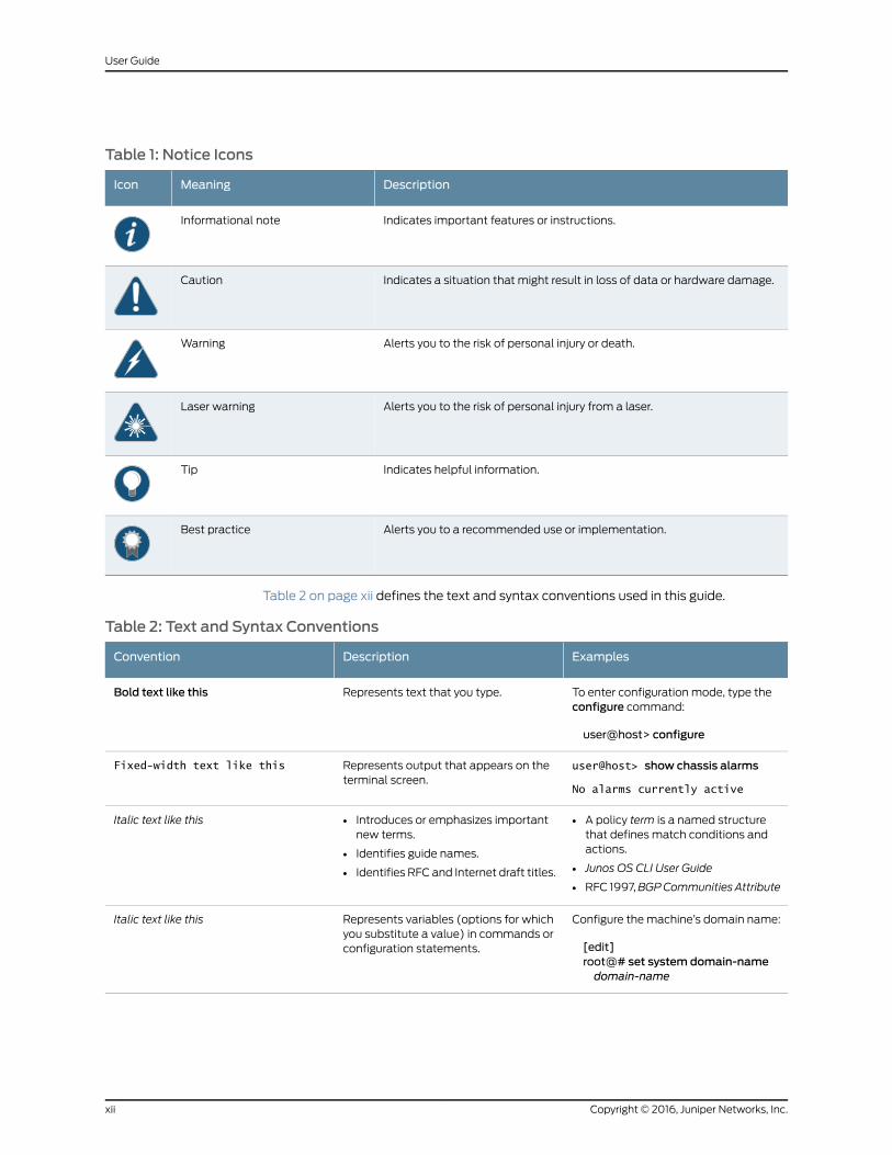
Table 1: Notice Icons
DescriptionMeaningIcon
Indicates important features or instructions.Informational note
Indicates a situation that might result in loss of data or hardware damage.Caution
Alerts you to the risk of personal injury or death.Warning
Alerts you to the risk of personal injury from a laser.Laser warning
Indicates helpful information.Tip
Alerts you to a recommended use or implementation.Best practice
Table 2 on page xii defines the text and syntax conventions used in this guide.
Table 2: Text and Syntax Conventions
ExamplesDescriptionConvention
To enter configuration mode, type theconfigure command:
user@host> configure
Represents text that you type.Bold text like this
user@host> show chassis alarms
No alarms currently active
Represents output that appears on theterminal screen.
Fixed-width text like this
• A policy term is a named structurethat defines match conditions andactions.
• Junos OS CLI User Guide
• RFC 1997,BGPCommunities Attribute
• Introduces or emphasizes importantnew terms.
• Identifies guide names.
• Identifies RFC and Internet draft titles.
Italic text like this
Configure themachine’s domain name:
[edit]root@# set system domain-namedomain-name
Represents variables (options for whichyou substitute a value) in commands orconfiguration statements.
Italic text like this
Copyright © 2016, Juniper Networks, Inc.xii
User Guide
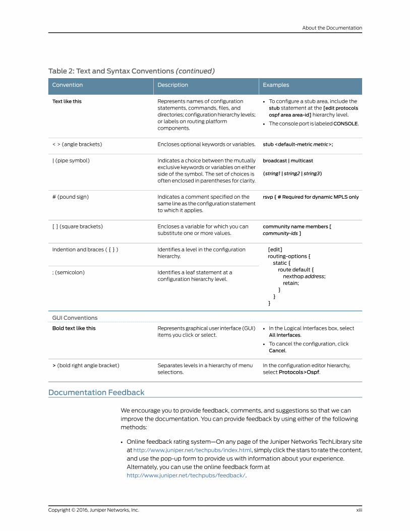
Table 2: Text and Syntax Conventions (continued)
ExamplesDescriptionConvention
• To configure a stub area, include thestub statement at the [edit protocolsospf area area-id] hierarchy level.
• Theconsoleport is labeledCONSOLE.
Represents names of configurationstatements, commands, files, anddirectories; configurationhierarchy levels;or labels on routing platformcomponents.
Text like this
stub <default-metricmetric>;Encloses optional keywords or variables.< > (angle brackets)
broadcast | multicast
(string1 | string2 | string3)
Indicates a choice between themutuallyexclusive keywords or variables on eitherside of the symbol. The set of choices isoften enclosed in parentheses for clarity.
| (pipe symbol)
rsvp { # Required for dynamicMPLS onlyIndicates a comment specified on thesame lineas theconfiguration statementto which it applies.
# (pound sign)
community namemembers [community-ids ]
Encloses a variable for which you cansubstitute one or more values.
[ ] (square brackets)
[edit]routing-options {static {route default {nexthop address;retain;
}}
}
Identifies a level in the configurationhierarchy.
Indention and braces ( { } )
Identifies a leaf statement at aconfiguration hierarchy level.
; (semicolon)
GUI Conventions
• In the Logical Interfaces box, selectAll Interfaces.
• To cancel the configuration, clickCancel.
Representsgraphicaluser interface(GUI)items you click or select.
Bold text like this
In the configuration editor hierarchy,select Protocols>Ospf.
Separates levels in a hierarchy of menuselections.
> (bold right angle bracket)
Documentation Feedback
We encourage you to provide feedback, comments, and suggestions so that we can
improve the documentation. You can provide feedback by using either of the following
methods:
• Online feedback rating system—On any page of the Juniper Networks TechLibrary site
athttp://www.juniper.net/techpubs/index.html, simply click the stars to rate thecontent,
and use the pop-up form to provide us with information about your experience.
Alternately, you can use the online feedback form at
http://www.juniper.net/techpubs/feedback/.
xiiiCopyright © 2016, Juniper Networks, Inc.
About the Documentation
• E-mail—Sendyourcommentsto [email protected]. Includethedocument
or topic name, URL or page number, and software version (if applicable).
Requesting Technical Support
Technical product support is available through the JuniperNetworksTechnicalAssistance
Center (JTAC). If you are a customer with an active J-Care or Partner Support Service
support contract, or are covered under warranty, and need post-sales technical support,
you can access our tools and resources online or open a case with JTAC.
• JTAC policies—For a complete understanding of our JTAC procedures and policies,
review the JTAC User Guide located at
http://www.juniper.net/us/en/local/pdf/resource-guides/7100059-en.pdf.
• Product warranties—For product warranty information, visit
http://www.juniper.net/support/warranty/.
• JTAC hours of operation—The JTAC centers have resources available 24 hours a day,
7 days a week, 365 days a year.
Self-Help Online Tools and Resources
For quick and easy problem resolution, Juniper Networks has designed an online
self-service portal called the Customer Support Center (CSC) that provides youwith the
following features:
• Find CSC offerings: http://www.juniper.net/customers/support/
• Search for known bugs: http://www2.juniper.net/kb/
• Find product documentation: http://www.juniper.net/techpubs/
• Find solutions and answer questions using our Knowledge Base: http://kb.juniper.net/
• Download the latest versions of software and review release notes:
http://www.juniper.net/customers/csc/software/
• Search technical bulletins for relevant hardware and software notifications:
http://kb.juniper.net/InfoCenter/
• Join and participate in the Juniper Networks Community Forum:
http://www.juniper.net/company/communities/
• Open a case online in the CSC Case Management tool: http://www.juniper.net/cm/
Toverify serviceentitlementbyproduct serial number, useourSerialNumberEntitlement
(SNE) Tool: https://tools.juniper.net/SerialNumberEntitlementSearch/
Opening a Casewith JTAC
You can open a case with JTAC on theWeb or by telephone.
• Use the Case Management tool in the CSC at http://www.juniper.net/cm/.
• Call 1-888-314-JTAC (1-888-314-5822 toll-free in the USA, Canada, and Mexico).
Copyright © 2016, Juniper Networks, Inc.xiv
User Guide
For international or direct-dial options in countries without toll-free numbers, see
http://www.juniper.net/support/requesting-support.html.
xvCopyright © 2016, Juniper Networks, Inc.
About the Documentation

Copyright © 2016, Juniper Networks, Inc.xvi
User Guide
PART 1
Contrail Service Orchestration
• Contrail Service Orchestration Introduction on page 3
1Copyright © 2016, Juniper Networks, Inc.

Copyright © 2016, Juniper Networks, Inc.2
User Guide
CHAPTER 1
Contrail Service OrchestrationIntroduction
• Contrail Service Orchestration Overview on page 3
• Contrail Service Orchestration Licensing on page 4
Contrail Service Orchestration Overview
Contrail Service Orchestration is a suite of products for designing and deploying network
services in the Cloud CPE Centralized DeploymentModel. Contrail Service Orchestration
provides a RESTful API to connect with service providers’ operational support systems
(OSS) and business support systems (BSS) applications and is responsible for many
management and network orchestration (MANO) activities in the deployment. Contrail
Service Orchestration consists of the following components:
• Administration Portal, which is an application that you use to manage resources,
customers, andavailability of network services throughagraphical user interface (GUI).
Administration Portal uses the RESTful APIs of other Contrail Service Orchestration
components.
• Cloud CPE Tenant Site and Service Manager and its auxiliary component, Identity and
AccessManager,whichmanagecustomersandmapeachcustomer’snetworkservices
to theappropriategateway resources, suchas theLayer 2access interfacesand routing
instances. These applications provide northbound RESTful APIs to which you can
connect OSS/BSS systems.
• Customer Portal, which is an application that you can provide to customers to enable
them tomanage sites and services for their organizations through a GUI. Customer
Portal uses the RESTful APIs of other Contrail Service Orchestration components.
• Network Service Designer, which enables design, creation, management, and
configuration of network services through a GUI. Network services are stored in the
network service catalog.
• Network Service Orchestrator, which is responsible for ETSI-compliant management
of the life cycle of network service instances. This application provides a northbound
RESTful API to which you can connect OSS/BSS systems.
• Service and InfrastructureMonitor, whichworks with Icinga, an open source enterprise
monitoringsystemtoprovidedataabout theCloudCPECentralizedDeploymentModel,
3Copyright © 2016, Juniper Networks, Inc.
such as the status of virtualized network functions (VNFs), virtual machines (VMs),
and physical servers; information about physical servers’ resources; components of a
network service (VNFs and VMs hosting a VNF); counters and other information for
VNFs; and software components running in Contrail Cloud Platform.
• VNFManager, which creates VNF instances andmanages their life cycles.
This user guide provides information about using the Contrail Service Orchestration
components with GUIs. For information about installing Contrail Service Orchestration
components, see the Cloud CPE Centralized Deployment Model Deployment Guide. For
information about the REST APIs, see the Contrail Service Orchestration API Reference
documentation.
RelatedDocumentation
Contrail Service Orchestration Licensing on page 4•
• Customer Portal Overview on page 37
• Network Service Designer Overview on page 61
• Service and Infrastructure Monitor Overview on page 89
Contrail Service Orchestration Licensing
Youmust have licenses to download and use Contrail Service Orchestration. When you
order licenses, you receive the information you need to download and use the product.
If youdidnotorder the licenses, contact your account teamor JuniperNetworksCustomer
Care for assistance.
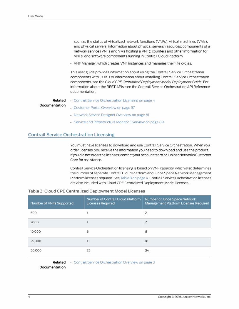
Contrail ServiceOrchestration licensing is based onVNF capacity, which also determines
the number of separate Contrail CloudPlatformand Junos SpaceNetworkManagement
Platform licenses required. SeeTable 3 onpage4. Contrail ServiceOrchestration licenses
are also included with Cloud CPE Centralized Deployment Model licenses.
Table 3: Cloud CPE Centralized Deployment Model Licenses
Number of Junos Space NetworkManagement Platform Licenses Required
Number of Contrail Cloud PlatformLicenses RequiredNumber of VNFs Supported
21500
212000
8510,000
181325,000
342550,000
RelatedDocumentation
• Contrail Service Orchestration Overview on page 3
Copyright © 2016, Juniper Networks, Inc.4
User Guide
PART 2
Administration Portal
• Administration Portal Introduction on page 7
• Configuring Network Resources on page 11
• Configuring Customers on page 23
• Managing Objects on page 31
5Copyright © 2016, Juniper Networks, Inc.

Copyright © 2016, Juniper Networks, Inc.6
User Guide
CHAPTER 2
Administration Portal Introduction
• Administration Portal Overview on page 7
• Setting Up the Cloud CPE Centralized Deployment Model with Administration
Portal on page 8
• Accessing Administration Portal on page 9
Administration Portal Overview
Administration Portal offers service providers a convenient way to set up andmanage
resources, customers, and availability of network services through a graphical user
interface (GUI).
When you use Administration Portal, you are actually creating andmanaging objects
used by the following APIs in the Cloud CPE Centralized Deployment Model:
• Cloud CPE Tenant, Site and Service Manager APIs, which manage customers (also
called tenants), manage customer sites, andmap each customer’s network services
to theappropriategateway resources, suchas theLayer 2access interfacesand routing
instances.
• Identity and Access Manager APIs, which manage identifiers and roles for customers
and users.
• NetworkServiceOrchestrationAPIs,whichmanagenetworkservicesandcommunicate
with Contrail OpenStack, the virtualized infrastructure manager (VIM).
• Contrail OpenStack API, which manages network points of presence (POPs), service
chains, and virtual machines (VMs) that contain service chains.
You can also set up andmanage the Cloud CPE Centralized Deployment Model through
API calls, eithermanuallyor fromyouroperational support systemsandbusinesssupport
systems (OSS/BSS). This method is more complex, however, and, if you use your own
OSS/BSS, requires development and integration work. Use of Administration Portal is
particularly beneficial for companies who require a turnkey solution and do not want to
expend effort on developing programs to set up andmanage the deployment through
APIs. Even if youplan to use your ownOSS/BSSsystems to set upandmanage theCloud
CPE Centralized Deployment Model in a production environment, Administration Portal
can prove useful for demonstrations and trials of the deployment.
7Copyright © 2016, Juniper Networks, Inc.
RelatedDocumentation
Setting Up the Cloud CPE Centralized Deployment Model with Administration Portal
on page 8
•
• Accessing Administration Portal on page 9
Setting Up the Cloud CPE Centralized Deployment Model with Administration Portal
In the Cloud CPE Centralized Deployment Model, end users at a specific customer site
access most network services in a regional point of presence (POP), andmight access
a few specialist network services in the central POP. Using Administration Portal, you
createandconfigure the resources for eachPOP, thencreateandconfigure thecustomers
and sites that access network services in the POP.
You use the following workflow to set up each POP in the Cloud CPE Centralized
Deployment Model with Administration Portal:
1. Create a virtualized infrastructure manager (VIM).
2. Create an element management system (EMS).
3. Createoneormore resourcepools—thesetof resources, excluding thevirtual networks
usedwithin customers’ organizations, that you use to instantiate andmanage a group
of virtualized network functions (VNFs).
4. Enable each resource pool.
5. Create the POP.
6. Createphysical networkelements (PNEs)—physical networkdevices that youmanage
through a Network Functions Virtualization (NFV) implementation.
7. Create one or more customers—the organizations that use the network services that
you provide.
AdministrationPortal automatically creates a transit network or hub for the customer.
A transit network is a virtual network for the customer’s organization that transports
traffic from one site to another and from a site to the Internet.
You then use the following workflow to set up each customer:
1. Createsites—thegeographical locations fromwhichendusersaccessnetwork services
in the customer’s organizations.
2. Create an administrative user—an administrator at the customer’s organization who
manages sites and network services in the organization’s network.
3. Allocate network services.
RelatedDocumentation
Accessing Administration Portal on page 9•
• Administration Portal Overview on page 7
• VIMManagement Overview on page 11
• EMSManagement Overview on page 13
Copyright © 2016, Juniper Networks, Inc.8
User Guide
• Resource Pool Management Overview on page 14
• POPManagement Overview on page 17
• Tenant Management Overview on page 23
Accessing Administration Portal
To start Administration Portal:
1. ReviewtheKeystoneusernameandpassword that youdefined forContrailOpenStack.
You can view these settings on the Contrail Configure and Control Node in the files
/etc/contrail/keystonerc and /etc/contrail/openstackrc.
2. Using aWeb browser, access the URL for Administration Portal.
For example, if the IP address of the virtual machine (VM) on which Administration
Portal resides is 192.0.2.1, the URL is http://192.0.2.1/admin-portal-ui/index.html.
3. Log in with the Keystone username and password that you specified for Contrail
OpenStack.
The VIMManagement page appears.
RelatedDocumentation
• Administration Portal Overview on page 7
• VIMManagement Overview on page 11
9Copyright © 2016, Juniper Networks, Inc.
Chapter 2: Administration Portal Introduction

Copyright © 2016, Juniper Networks, Inc.10
User Guide
CHAPTER 3
Configuring Network Resources
• VIMManagement Overview on page 11
• Creating a VIM on page 12
• EMSManagement Overview on page 13
• Creating an EMS on page 13
• Resource Pool Management Overview on page 14
• Creating a Resource Pool on page 15
• Activating and Deactivating Resource Pools on page 16
• POPManagement Overview on page 17
• Creating a POP on page 17
• Device Management Overview on page 18
• Creating Devices on page 19
VIMManagement Overview
Thevirtualized infrastructuremanager (VIM) in aNetwork FunctionsVirtualization (NFV)
implementationmanages the hardware and software resources that the service provider
uses to create service chains and deliver network services to customers. The network
service orchestration component notifies the VIM when a customer activates a network
service. In the Cloud CPE Centralized Deployment Model, Contrail OpenStack provides
the VIM, and Network Service Orchestrator provides the network service orchestration.
The Contrail Cloud Reference Architecture (CCRA) provides the hardware and software
resources for the creation of service chains and for delivery of network services in the
service provider’s cloud.
You create one VIM object for each POP in your network. Because the CCRA provides
the VIM, you specify several Contrail OpenStack settings when you create a VIM.
The VIMManagement page displays some of the settings for a VIM. For complete
information about the settings for a VIM, see Table 4 on page 12.
RelatedDocumentation
Creating a VIM on page 12•
• Administration Portal Overview on page 7
• Modifying an Object on page 31
11Copyright © 2016, Juniper Networks, Inc.
• Deleting an Object on page 32
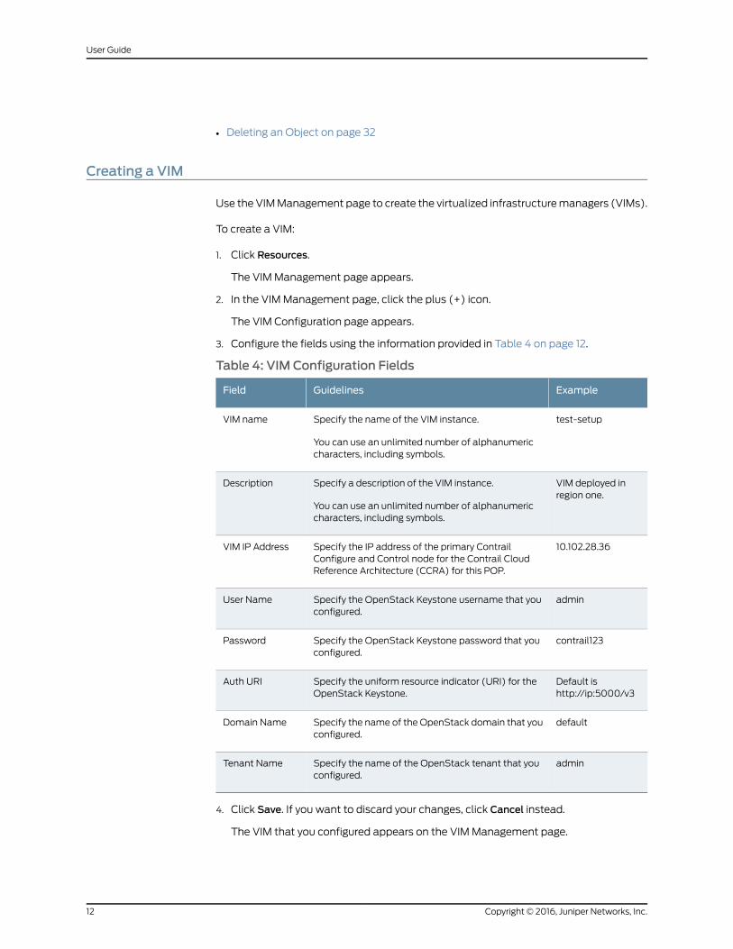
Creating a VIM
Use the VIMManagement page to create the virtualized infrastructuremanagers (VIMs).
To create a VIM:
1. Click Resources.
The VIMManagement page appears.
2. In the VIMManagement page, click the plus (+) icon.
The VIM Configuration page appears.
3. Configure the fields using the information provided in Table 4 on page 12.
Table 4: VIM Configuration Fields
ExampleGuidelinesField
test-setupSpecify the name of the VIM instance.
You can use an unlimited number of alphanumericcharacters, including symbols.
VIM name
VIM deployed inregion one.
Specify a description of the VIM instance.
You can use an unlimited number of alphanumericcharacters, including symbols.
Description
10.102.28.36Specify the IP address of the primary ContrailConfigure and Control node for the Contrail CloudReference Architecture (CCRA) for this POP.
VIM IP Address
adminSpecify the OpenStack Keystone username that youconfigured.
User Name
contrail123Specify the OpenStack Keystone password that youconfigured.
Password
Default ishttp://ip:5000/v3
Specify the uniform resource indicator (URI) for theOpenStack Keystone.
Auth URI
defaultSpecify the name of the OpenStack domain that youconfigured.
Domain Name
adminSpecify the name of the OpenStack tenant that youconfigured.
Tenant Name
4. Click Save. If you want to discard your changes, click Cancel instead.
The VIM that you configured appears on the VIMManagement page.
Copyright © 2016, Juniper Networks, Inc.12
User Guide
RelatedDocumentation
VIMManagement Overview on page 11•
• Creating an EMS on page 13
EMSManagement Overview
The element management system (EMS) in a Network Functions Virtualization (NFV)
implementation provides network management of the virtualized network functions
(VNFs) and physical network elements (PNEs). The VNFManager notifies the EMS that
it needs to provide element management for a new VNF or PNE.
In the Cloud CPE Centralized Deployment Model, the Junos Space Virtual Appliance
provides theEMS,and resideson theContrail ServiceOrchestrationNode.Administration
Portal automatically detects and adds an object for the EMS, using the name that you
specify when you deploy the Junos Space Virtual Appliance. You need to configure some
settings for the EMS, so that the virtual appliance can communicate with other
components in the deployment. For a redundant Contrail Service Orchestration
configuration, configure only the primary Junos Space Virtual Appliance. When you
configure the virtual appliance, you specify the information displayed on the EMS
Management page.
The EMSManagement page displays some of the settings that you specify when you
configure an EMS. For complete information about the settings for an EMS, see Table 5
on page 14.
RelatedDocumentation
Creating an EMS on page 13•
• Administration Portal Overview on page 7
• Modifying an Object on page 31
• Deleting an Object on page 32
Creating an EMS
Use the EMSManagement page to configure the primary instance of each element
management system (EMS) that you use for the Cloud CPE Centralized Deployment
Model. Administration Portal automatically adds an object for the EMS, using the name
that you specify when you deploy the Junos Space Virtual Appliance.
Before You Begin
• Verify that the VIMManagement page displays the virtualized infrastructuremanagers
(VIMs).
To configure an EMS:
1. Click Resources.
2. In the left navigation pane, click EMS.
The EMSManagement page appears.
13Copyright © 2016, Juniper Networks, Inc.
Chapter 3: Configuring Network Resources
3. Click the plus (+) icon.
The EMS Configuration page appears.
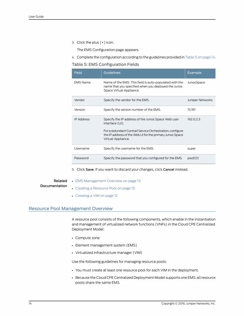
4. Complete the configurationaccording to theguidelinesprovided inTable 5onpage 14.
Table 5: EMS Configuration Fields
ExampleGuidelinesField
JunosSpaceName of the EMS. This field is auto-populated with thename that you specified when you deployed the JunosSpace Virtual Appliance.
EMS Name
Juniper NetworksSpecify the vendor for the EMS.Vendor
15.1R1Specify the version number of the EMS.Version
192.0.2.3Specify the IP address of the Junos SpaceWeb userinterface (UI).
Fora redundantContrailServiceOrchestration, configurethe IPaddressof theWebUI for theprimary JunosSpaceVirtual Appliance.
IP Address
superSpecify the username for the EMS.Username
pwd123Specify the password that you configured for the EMS.Password
5. Click Save. If you want to discard your changes, click Cancel instead.
RelatedDocumentation
EMSManagement Overview on page 13•
• Creating a Resource Pool on page 15
• Creating a VIM on page 12
Resource Pool Management Overview
A resource pool consists of the following components, which enable in the instantiation
andmanagement of virtualized network functions (VNFs) in the Cloud CPE Centralized
Deployment Model:
• Compute zone
• Element management system (EMS)
• Virtualized infrastructure manager (VIM)
Use the following guidelines for managing resource pools:
• Youmust create at least one resource pool for each VIM in the deployment.
• Because theCloudCPECentralizedDeploymentModel supports oneEMS, all resource
pools share the same EMS.
Copyright © 2016, Juniper Networks, Inc.14
User Guide
• Youmaydefine resourcepoolswith thesameVIMandEMS,butwithdifferent compute
zones.
• Defining multiple compute zones enables scaling of the deployment within a POP.
The Resource Pool Management page displays some of the settings for a resource pool.
For complete information about the settings for a resource pool, see Table 6 on page 15.
RelatedDocumentation
Activating and Deactivating Resource Pools on page 16•
• Administration Portal Overview on page 7
• Modifying an Object on page 31
• Deleting an Object on page 32
Creating a Resource Pool
Use the Resource Pool Management page to define the objects in the network point of
presence (POP) that instantiate andmanage VNFs.
Before You Begin
• Create the virtualized infrastructure manager (VIM) for the POP.
• Create the element management system (EMS) for the POP.
To create a resource pool:
1. Click Resources.
2. In the left navigation pane, click Resource Pool.
The Resource Pool Management page appears.
3. Click the plus (+) icon.
The Resource Pool Configuration page appears.
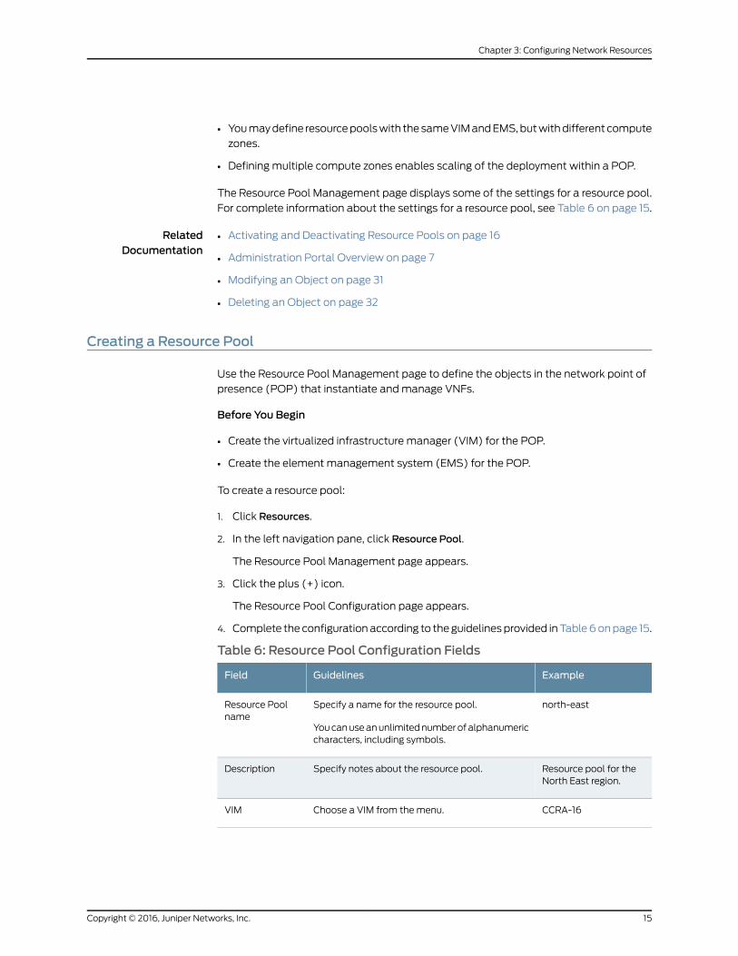
4. Complete the configurationaccording to theguidelinesprovided inTable6onpage 15.
Table 6: Resource Pool Configuration Fields
ExampleGuidelinesField
north-eastSpecify a name for the resource pool.
Youcanuseanunlimitednumberofalphanumericcharacters, including symbols.
Resource Poolname
Resource pool for theNorth East region.
Specify notes about the resource pool.Description
CCRA-16Choose a VIM from themenu.VIM
15Copyright © 2016, Juniper Networks, Inc.
Chapter 3: Configuring Network Resources
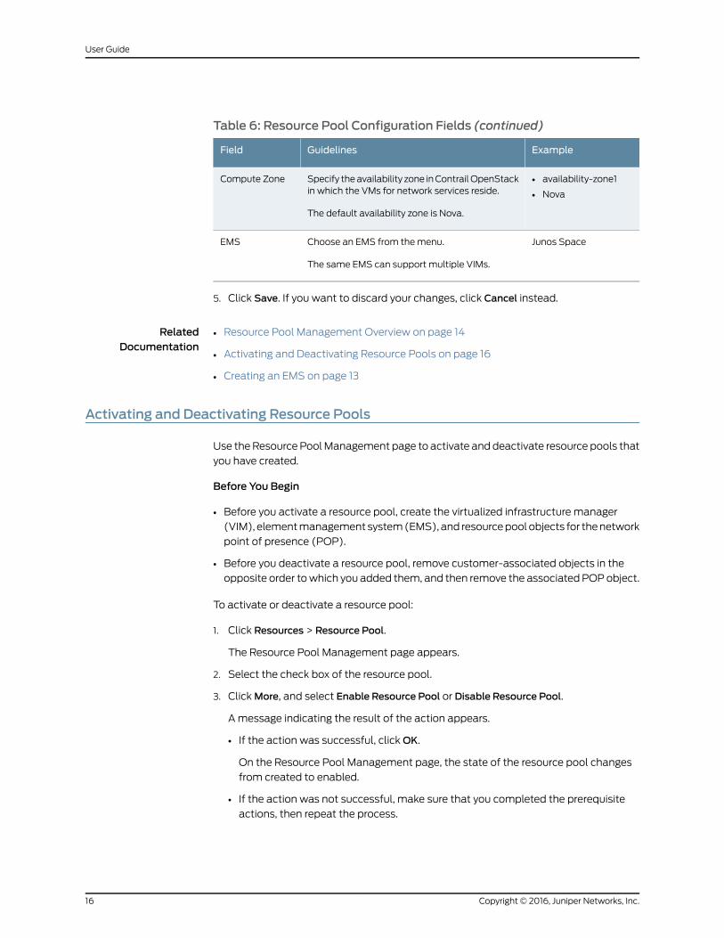
Table 6: Resource Pool Configuration Fields (continued)
ExampleGuidelinesField
• availability-zone1
• Nova
Specify theavailability zone inContrailOpenStackin which the VMs for network services reside.
The default availability zone is Nova.
Compute Zone
Junos SpaceChoose an EMS from themenu.
The same EMS can support multiple VIMs.
EMS
5. Click Save. If you want to discard your changes, click Cancel instead.
RelatedDocumentation
Resource Pool Management Overview on page 14•
• Activating and Deactivating Resource Pools on page 16
• Creating an EMS on page 13
Activating and Deactivating Resource Pools
Use theResource PoolManagement page to activate and deactivate resource pools that
you have created.
Before You Begin
• Before you activate a resource pool, create the virtualized infrastructure manager
(VIM), elementmanagement system(EMS), and resourcepoolobjects for thenetwork
point of presence (POP).
• Before you deactivate a resource pool, remove customer-associated objects in the
opposite order towhich you added them, and then remove the associated POPobject.
To activate or deactivate a resource pool:
1. Click Resources > Resource Pool.
The Resource Pool Management page appears.
2. Select the check box of the resource pool.
3. ClickMore, and select Enable Resource Pool or Disable Resource Pool.
A message indicating the result of the action appears.
• If the action was successful, clickOK.
On the Resource Pool Management page, the state of the resource pool changes
from created to enabled.
• If the action was not successful, make sure that you completed the prerequisite
actions, then repeat the process.
Copyright © 2016, Juniper Networks, Inc.16
User Guide
RelatedDocumentation
Resource Pool Management Overview on page 14•
• Creating a POP on page 17
• Creating a Resource Pool on page 15
POPManagement Overview
InaNetworkFunctionsVirtualization (NFV) implementation, anetworkpointofpresence
(POP) is a location at which a service provider instantiates a network function, such as
a virtualized network function (VNF).
The Cloud CPE Centralized Deployment Model supports multiple POPs. A scaled
deployment contains a central POP andmultiple regional POPs. End users at customer
sites in a specific geographic region access most network services in their regional POP,
andmight access a few specialist services in the central POP. Each POP contains a
dedicated Contrail Cloud Reference Architecture, which provides one virtualized
infrastructure manager (VIM).
Contrail CloudPlatformcreates one virtualmachine (VM) for eachVNFused in theCloud
CPE Centralized Deployment Model. Contrail uses amanagement virtual network to
assign IPaddresses to theEthernetmanagementports for theseVMs. Inaddition,Contrail
uses an Internet gateway next hop to enable Internet access for the VMs.
When you configure a POPwith Administration Portal, you specify:
• The universally unique identifier (UUID) for the Contrail virtual management network
to allow access to the VNFs from the POP.
• The UUID for the Internet gateway next hop in Contrail to enable access to the VMs
from the Internet.
The POPManagement page displays some of the settings that you specify when you
configure a POP. For complete information about the settings for a POP, see Table 7 on
page 18.
RelatedDocumentation
Creating a POP on page 17•
• Administration Portal Overview on page 7
• Modifying an Object on page 31
• Deleting an Object on page 32
Creating a POP
Use the POPManagement page to create a network point of presence (POP).
Before You Begin
• Create the virtualized infrastructure manager (VIM), element management system
(EMS), and resource pool objects for the POP.
17Copyright © 2016, Juniper Networks, Inc.
Chapter 3: Configuring Network Resources
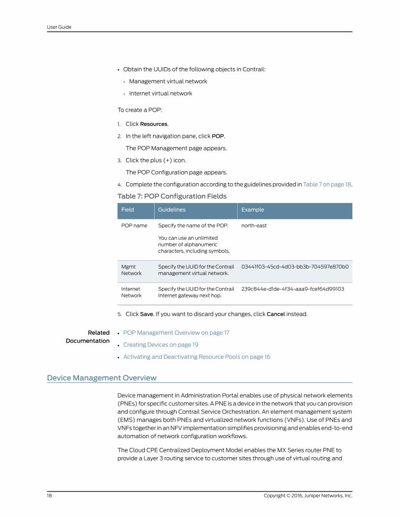
• Obtain the UUIDs of the following objects in Contrail:
• Management virtual network
• Internet virtual network
To create a POP:
1. Click Resources.
2. In the left navigation pane, click POP.
The POPManagement page appears.
3. Click the plus (+) icon.
The POP Configuration page appears.
4. Complete the configuration according to the guidelines provided inTable 7 onpage 18.
Table 7: POP Configuration Fields
ExampleGuidelinesField
north-eastSpecify the name of the POP.
You can use an unlimitednumber of alphanumericcharacters, including symbols.
POP name
03441f03-45cd-4d03-bb3b-704597e870b0Specify theUUID for theContrailmanagement virtual network.
MgmtNetwork
239c844e-d1de-4f34-aaa9-fcef64d99103Specify theUUID for theContrailInternet gateway next hop.
InternetNetwork
5. Click Save. If you want to discard your changes, click Cancel instead.
RelatedDocumentation
POPManagement Overview on page 17•
• Creating Devices on page 19
• Activating and Deactivating Resource Pools on page 16
DeviceManagement Overview
Device management in Administration Portal enables use of physical network elements
(PNEs) for specific customer sites. APNE is adevice in thenetwork that youcanprovision
and configure through Contrail Service Orchestration. An element management system
(EMS)manages both PNEs and virtualized network functions (VNFs). Use of PNEs and
VNFs together in anNFV implementation simplifiesprovisioningandenablesend-to-end
automation of network configuration workflows.
The Cloud CPE Centralized Deployment Model enables the MX Series router PNE to
provide a Layer 3 routing service to customer sites through use of virtual routing and
Copyright © 2016, Juniper Networks, Inc.18
User Guide
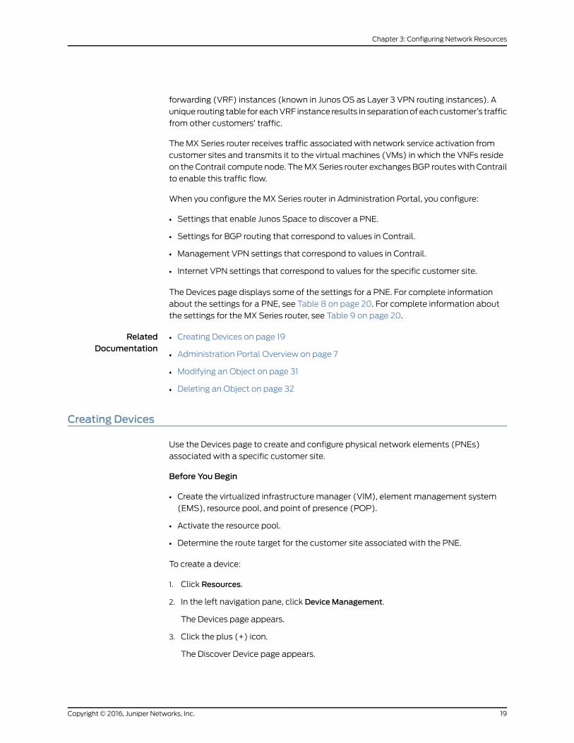
forwarding (VRF) instances (known in Junos OS as Layer 3 VPN routing instances). A
unique routing table for eachVRF instance results in separationof eachcustomer’s traffic
from other customers’ traffic.
The MX Series router receives traffic associated with network service activation from
customer sites and transmits it to the virtual machines (VMs) in which the VNFs reside
on the Contrail compute node. TheMXSeries router exchanges BGP routeswith Contrail
to enable this traffic flow.
When you configure the MX Series router in Administration Portal, you configure:
• Settings that enable Junos Space to discover a PNE.
• Settings for BGP routing that correspond to values in Contrail.
• Management VPN settings that correspond to values in Contrail.
• Internet VPN settings that correspond to values for the specific customer site.
The Devices page displays some of the settings for a PNE. For complete information
about the settings for a PNE, see Table 8 on page 20. For complete information about
the settings for the MX Series router, see Table 9 on page 20.
RelatedDocumentation
Creating Devices on page 19•
• Administration Portal Overview on page 7
• Modifying an Object on page 31
• Deleting an Object on page 32
Creating Devices
Use the Devices page to create and configure physical network elements (PNEs)
associated with a specific customer site.
Before You Begin
• Create the virtualized infrastructure manager (VIM), element management system
(EMS), resource pool, and point of presence (POP).
• Activate the resource pool.
• Determine the route target for the customer site associated with the PNE.
To create a device:
1. Click Resources.
2. In the left navigation pane, click DeviceManagement.
The Devices page appears.
3. Click the plus (+) icon.
The Discover Device page appears.
19Copyright © 2016, Juniper Networks, Inc.
Chapter 3: Configuring Network Resources
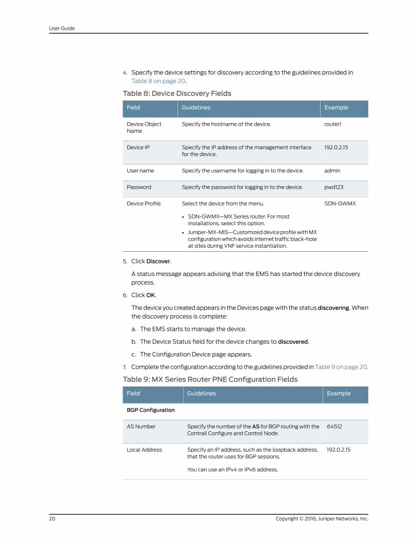
4. Specify the device settings for discovery according to the guidelines provided in
Table 8 on page 20.
Table 8: Device Discovery Fields
ExampleGuidelinesField
router1Specify the hostname of the device.Device ObjectName
192.0.2.15Specify the IP address of the management interfacefor the device.
Device IP
adminSpecify the username for logging in to the device.User name
pwd123Specify the password for logging in to the device.Password
SDN-GWMXSelect the device from themenu.
• SDN-GWMX—MX Series router. For mostinstallations, select this option.
• Juniper-MX-MIS—CustomizeddeviceprofilewithMXconfigurationwhichavoids internet traffic black-holeat sites during VNF service instantiation.
Device Profile
5. Click Discover.
A status message appears advising that the EMS has started the device discovery
process.
6. ClickOK.
The device you created appears in theDevices pagewith the statusdiscovering.When
the discovery process is complete:
a. The EMS starts to manage the device.
b. The Device Status field for the device changes to discovered.
c. The Configuration Device page appears.
7. Complete theconfigurationaccording to theguidelinesprovided inTable9onpage20.
Table 9: MX Series Router PNE Configuration Fields
ExampleGuidelinesField
BGP Configuration
64512Specify the number of theAS for BGP routingwith theContrail Configure and Control Node.
AS Number
192.0.2.15Specify an IP address, such as the loopback address,that the router uses for BGP sessions.
You can use an IPv4 or IPv6 address.
Local Address
Copyright © 2016, Juniper Networks, Inc.20
User Guide
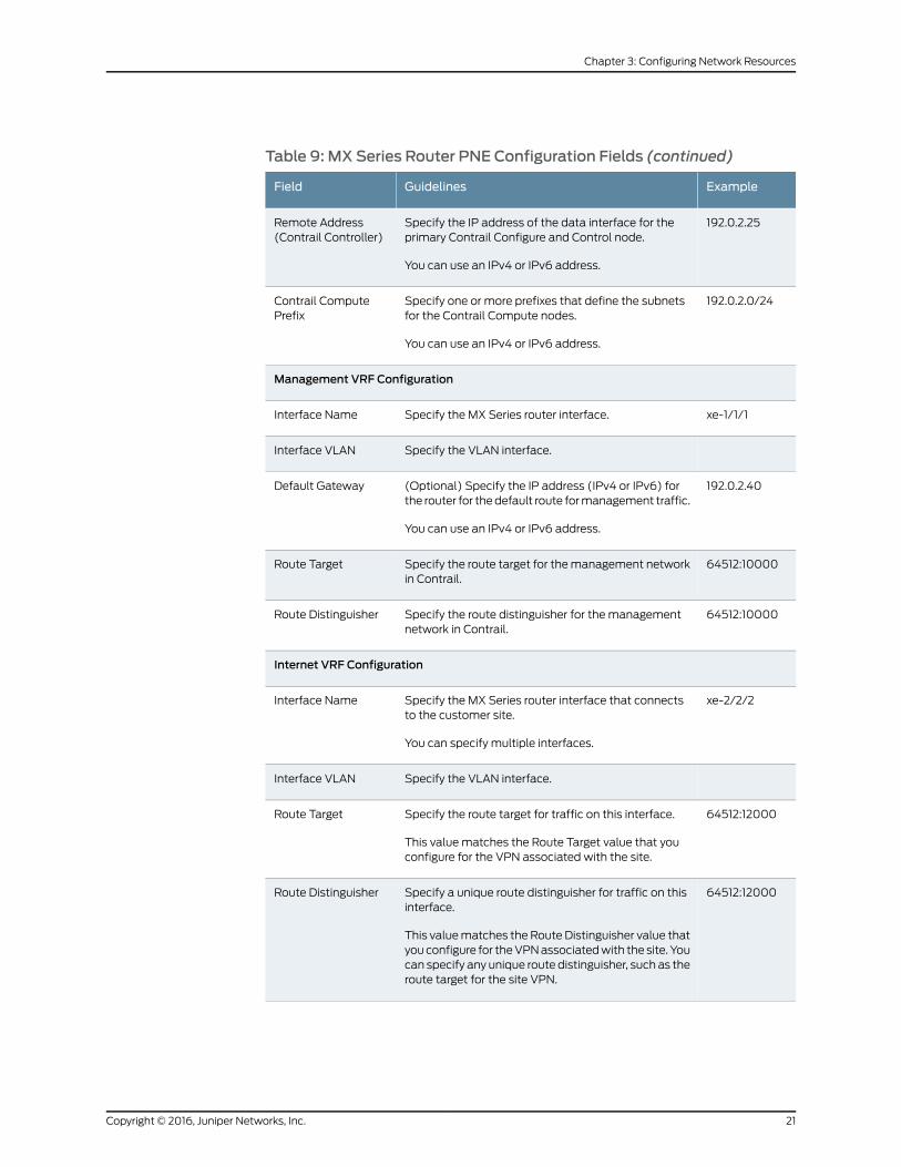
Table 9: MX Series Router PNE Configuration Fields (continued)
ExampleGuidelinesField
192.0.2.25Specify the IP address of the data interface for theprimary Contrail Configure and Control node.
You can use an IPv4 or IPv6 address.
Remote Address(Contrail Controller)
192.0.2.0/24Specify one or more prefixes that define the subnetsfor the Contrail Compute nodes.
You can use an IPv4 or IPv6 address.
Contrail ComputePrefix
Management VRF Configuration
xe-1/1/1Specify the MX Series router interface.Interface Name
Specify the VLAN interface.Interface VLAN
192.0.2.40(Optional) Specify the IP address (IPv4 or IPv6) forthe router for thedefault route formanagement traffic.
You can use an IPv4 or IPv6 address.
Default Gateway
64512:10000Specify the route target for themanagement networkin Contrail.
Route Target
64512:10000Specify the route distinguisher for the managementnetwork in Contrail.
Route Distinguisher
Internet VRF Configuration
xe-2/2/2Specify the MX Series router interface that connectsto the customer site.
You can specify multiple interfaces.
Interface Name
Specify the VLAN interface.Interface VLAN
64512:12000Specify the route target for traffic on this interface.
This value matches the Route Target value that youconfigure for the VPN associated with the site.
Route Target
64512:12000Specify a unique route distinguisher for traffic on thisinterface.
This valuematches the Route Distinguisher value thatyouconfigure for theVPNassociatedwith the site. Youcan specify any unique route distinguisher, such as theroute target for the site VPN.
Route Distinguisher
21Copyright © 2016, Juniper Networks, Inc.
Chapter 3: Configuring Network Resources
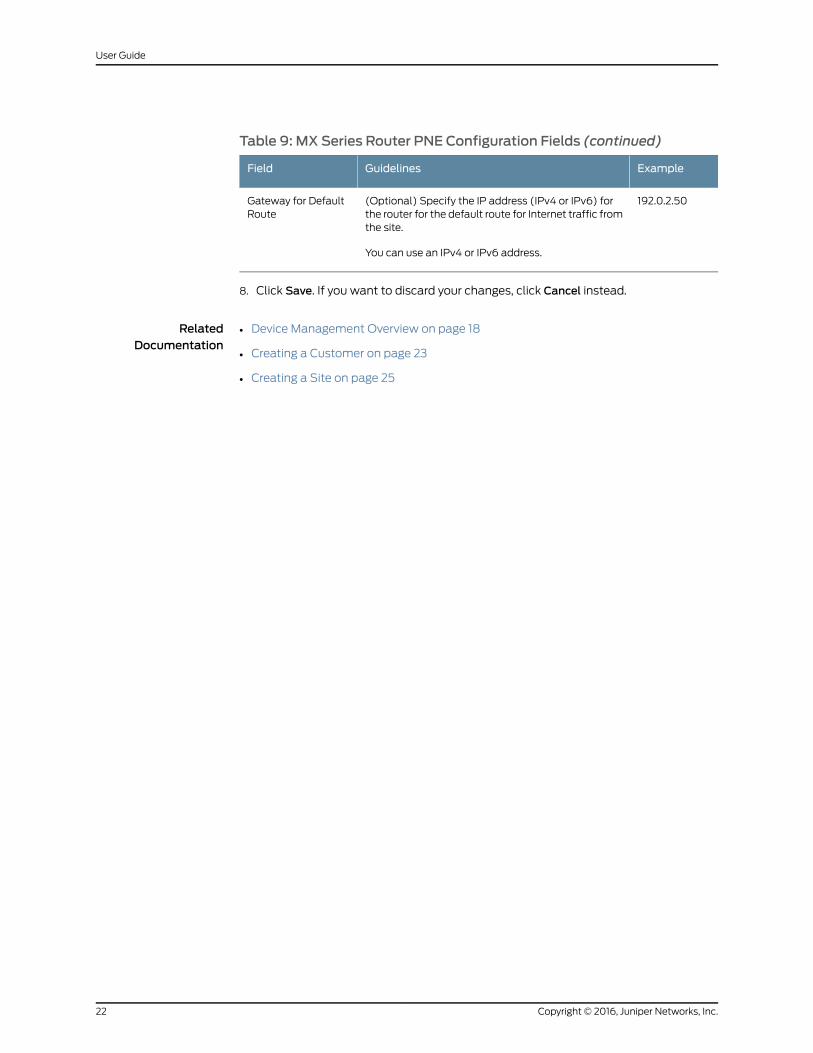
Table 9: MX Series Router PNE Configuration Fields (continued)
ExampleGuidelinesField
192.0.2.50(Optional) Specify the IP address (IPv4 or IPv6) forthe router for the default route for Internet traffic fromthe site.
You can use an IPv4 or IPv6 address.
Gateway for DefaultRoute
8. Click Save. If you want to discard your changes, click Cancel instead.
RelatedDocumentation
• Device Management Overview on page 18
• Creating a Customer on page 23
• Creating a Site on page 25
Copyright © 2016, Juniper Networks, Inc.22
User Guide
CHAPTER 4
Configuring Customers
• Tenant Management Overview on page 23
• Creating a Customer on page 23
• Creating an Administrative User on page 25
• Creating a Site on page 25
• Importing Sites from a File on page 27
• Allocating Network Services on page 29
Tenant Management Overview
A tenant in a Cloud CPE Centralized Deployment Model represents a customer who
accesses virtualized network functions (VNFs) in a service provider’s centralized cloud
through a Layer 3 VPN. You assign users and sites to customers in the Administration
Portal to represent the staff in thecustomer’s organizationand thegeographical locations
in the customer’s network. Youalso useAdministrationPortal to allocate network service
profiles to customers.
TheTenantspagedisplays someof the settings for a customer. For complete information
about the settings for a customer, see Table 10 on page 24.
RelatedDocumentation
Creating a Customer on page 23•
• Administration Portal Overview on page 7
• Modifying an Object on page 31
• Deleting an Object on page 32
Creating a Customer
Use the Tenants page to create customers and other objects associatedwith customers,
such as administrative users and sites.
Before You Begin
23Copyright © 2016, Juniper Networks, Inc.
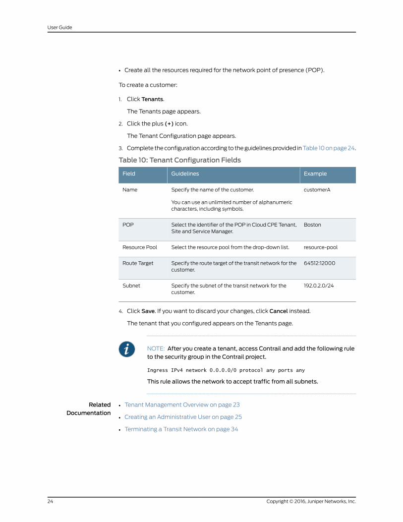
• Create all the resources required for the network point of presence (POP).
To create a customer:
1. Click Tenants.
The Tenants page appears.
2. Click the plus (+) icon.
The Tenant Configuration page appears.
3. Complete theconfigurationaccording to theguidelinesprovided inTable 10onpage24.
Table 10: Tenant Configuration Fields
ExampleGuidelinesField
customerASpecify the name of the customer.
You can use an unlimited number of alphanumericcharacters, including symbols.
Name
BostonSelect the identifier of the POP in Cloud CPE Tenant,Site and Service Manager.
POP
resource-poolSelect the resource pool from the drop-down list.Resource Pool
64512:12000Specify the route target of the transit network for thecustomer.
Route Target
192.0.2.0/24Specify the subnet of the transit network for thecustomer.
Subnet
4. Click Save. If you want to discard your changes, click Cancel instead.
The tenant that you configured appears on the Tenants page.
NOTE: After you create a tenant, access Contrail and add the following ruleto the security group in the Contrail project.
Ingress IPv4 network 0.0.0.0/0 protocol any ports any
This rule allows the network to accept traffic from all subnets.
RelatedDocumentation
Tenant Management Overview on page 23•
• Creating an Administrative User on page 25
• Terminating a Transit Network on page 34
Copyright © 2016, Juniper Networks, Inc.24
User Guide
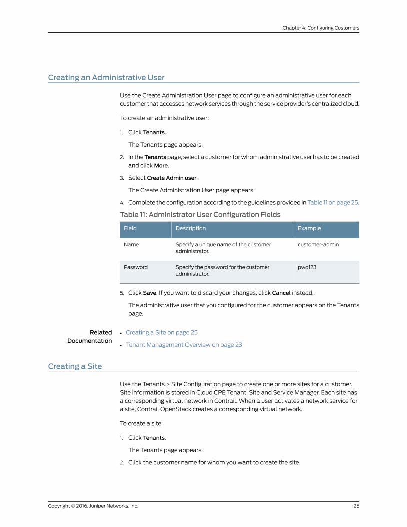
Creating an Administrative User
Use the Create Administration User page to configure an administrative user for each
customer that accessesnetwork services through the serviceprovider’s centralizedcloud.
To create an administrative user:
1. Click Tenants.
The Tenants page appears.
2. In theTenantspage, select a customer forwhomadministrative user has tobe created
and clickMore.
3. Select Create Admin user.
The Create Administration User page appears.
4. Complete theconfigurationaccording to theguidelinesprovided inTable 11 onpage25.
Table 11: Administrator User Configuration Fields
ExampleDescriptionField
customer-adminSpecify a unique name of the customeradministrator.
Name
pwd123Specify the password for the customeradministrator.
Password
5. Click Save. If you want to discard your changes, click Cancel instead.
The administrative user that you configured for the customer appears on the Tenants
page.
RelatedDocumentation
Creating a Site on page 25•
• Tenant Management Overview on page 23
Creating a Site
Use the Tenants > Site Configuration page to create one or more sites for a customer.
Site information is stored in Cloud CPE Tenant, Site and Service Manager. Each site has
a corresponding virtual network in Contrail. When a user activates a network service for
a site, Contrail OpenStack creates a corresponding virtual network.
To create a site:
1. Click Tenants.
The Tenants page appears.
2. Click the customer name for whom you want to create the site.
25Copyright © 2016, Juniper Networks, Inc.
Chapter 4: Configuring Customers
The list of existing sites for the customer appears.
3. Click the plus (+) icon.
The Site Configuration page appears.
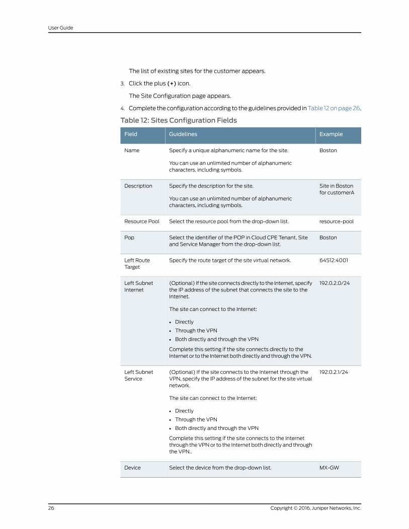
4. Complete theconfigurationaccording to theguidelinesprovided inTable 12onpage26.
Table 12: Sites Configuration Fields
ExampleGuidelinesField
BostonSpecify a unique alphanumeric name for the site.
You can use an unlimited number of alphanumericcharacters, including symbols.
Name
Site in Bostonfor customerA
Specify the description for the site.
You can use an unlimited number of alphanumericcharacters, including symbols.
Description
resource-poolSelect the resource pool from the drop-down list.Resource Pool
BostonSelect the identifier of the POP in Cloud CPE Tenant, Siteand Service Manager from the drop-down list.
Pop
64512:4001Specify the route target of the site virtual network.Left RouteTarget
192.0.2.0/24(Optional) If the site connectsdirectly to the Internet, specifythe IP address of the subnet that connects the site to theInternet.
The site can connect to the Internet:
• Directly
• Through the VPN
• Both directly and through the VPN
Complete this setting if the site connects directly to theInternet or to the Internet bothdirectly and through theVPN.
Left SubnetInternet
192.0.2.1/24(Optional) If the site connects to the Internet through theVPN, specify the IP address of the subnet for the site virtualnetwork.
The site can connect to the Internet:
• Directly
• Through the VPN
• Both directly and through the VPN
Complete this setting if the site connects to the Internetthrough theVPNor to the Internet both directly and throughthe VPN..
Left SubnetService
MX-GWSelect the device from the drop-down list.Device
Copyright © 2016, Juniper Networks, Inc.26
User Guide
5. Click Save. If you want to discard your changes, click Cancel instead.
The site that you configured appears on the sites page of the customer.
6. Click the check box of the site.
7. SelectMore > Advanced Configuration.
The Configure Device page appears.
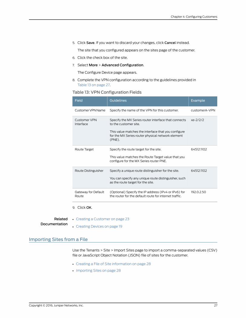
8. Complete the VPN configuration according to the guidelines provided in
Table 13 on page 27.
Table 13: VPN Configuration Fields
ExampleGuidelinesField
customerA-VPNSpecify the name of the VPN for this customer.CustomerVPNName
xe-2/2/2Specify the MX Series router interface that connectsto the customer site.
This value matches the interface that you configurefor the MX Series router physical network element(PNE).
Customer VPNInterface
64512:1102Specify the route target for the site.
This value matches the Route Target value that youconfigure for the MX Series router PNE.
Route Target
64512:1102Specify a unique route distinguisher for the site.
You can specify any unique route distinguisher, suchas the route target for the site.
Route Distinguisher
192.0.2.50(Optional) Specify the IP address (IPv4 or IPv6) forthe router for the default route for internet traffic.
Gateway for DefaultRoute
9. ClickOK.
RelatedDocumentation
Creating a Customer on page 23•
• Creating Devices on page 19
Importing Sites from a File
Use the Tenants > Site > Import Sites page to import a comma-separated values (CSV)
file or JavaScript Object Notation (JSON) file of sites for the customer.
• Creating a File of Site information on page 28
• Importing Sites on page 28
27Copyright © 2016, Juniper Networks, Inc.
Chapter 4: Configuring Customers
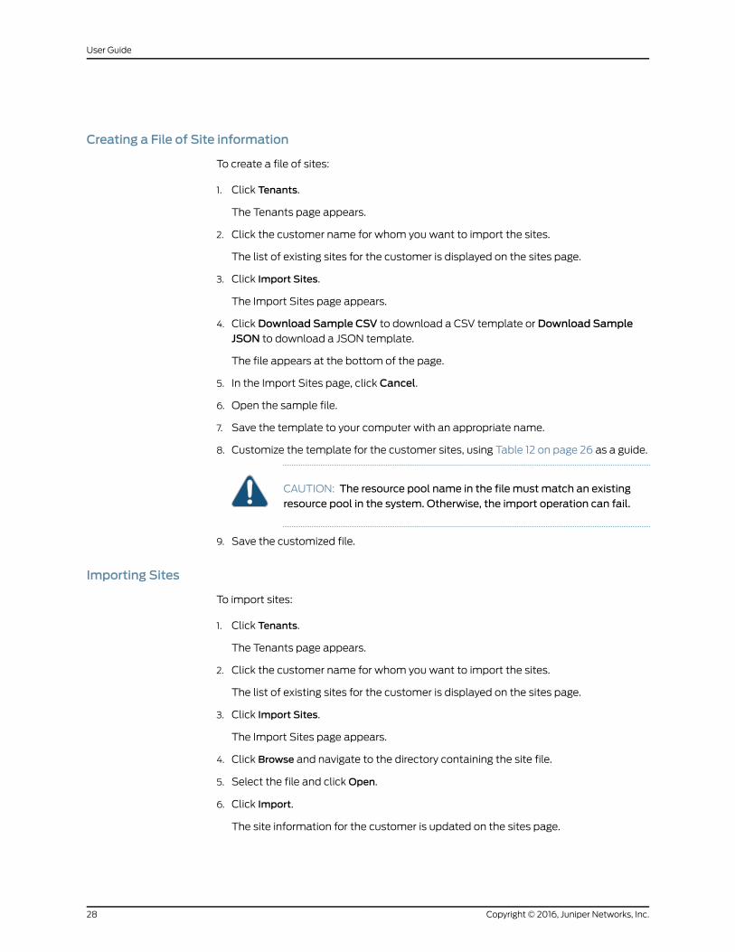
Creating a File of Site information
To create a file of sites:
1. Click Tenants.
The Tenants page appears.
2. Click the customer name for whom you want to import the sites.
The list of existing sites for the customer is displayed on the sites page.
3. Click Import Sites.
The Import Sites page appears.
4. Click Download Sample CSV to download a CSV template or Download SampleJSON to download a JSON template.
The file appears at the bottom of the page.
5. In the Import Sites page, click Cancel.
6. Open the sample file.
7. Save the template to your computer with an appropriate name.
8. Customize the template for the customer sites, using Table 12 on page 26 as a guide.
CAUTION: The resource pool name in the file must match an existingresource pool in the system. Otherwise, the import operation can fail.
9. Save the customized file.
Importing Sites
To import sites:
1. Click Tenants.
The Tenants page appears.
2. Click the customer name for whom you want to import the sites.
The list of existing sites for the customer is displayed on the sites page.
3. Click Import Sites.
The Import Sites page appears.
4. Click Browse and navigate to the directory containing the site file.
5. Select the file and clickOpen.
6. Click Import.
The site information for the customer is updated on the sites page.
Copyright © 2016, Juniper Networks, Inc.28
User Guide
RelatedDocumentation
Creating a Site on page 25•
Allocating Network Services
Use the Tenants page to create and save network services in Network Service Designer.
When setting up customers with Administration Portal, you must import the network
services and allocate them to customers. After the allocation, customers can see and
activate the network services in Customer Portal.
Before You Begin
• Create network services in Network Service Designer. See “Configuring Network
Services” on page 73 topic.
To allocate network services:
1. Click Tenants.
The Tenants page appears.
2. Select a customer and click Import & Assign Service Profiles.
All network services are imported and allocated to the customer.
RelatedDocumentation
• Creating a Transit Network on page 33
29Copyright © 2016, Juniper Networks, Inc.
Chapter 4: Configuring Customers

Copyright © 2016, Juniper Networks, Inc.30
User Guide
CHAPTER 5
Managing Objects
• Viewing Details for an Object on page 31
• Modifying an Object on page 31
• Deleting an Object on page 32
• Modifying a Site on page 32
• Deleting a Site on page 33
• Creating a Transit Network on page 33
• Terminating a Transit Network on page 34
Viewing Details for an Object
Use theDetailedViewpage toviewall theconfiguredparametersof anobject.Only some
of the configured parameters appear in the list of features on themain page.
To view details for an object:
• Right-click the object that youwant to see the detailed view for, or selectDetails from
theMoremenu.
• Alternatively, hoverover theobjectnameandclick theDetailedView icon thatappears
before it.
The Detailed View page appears showing the configuration information.
RelatedDocumentation
Modifying an Object on page 31•
• Deleting an Object on page 32
Modifying an Object
Use the pencil icon in the top right of a page to modify or edit an object on that page.
Tomodify an object:
1. Select the check box of the object that you want to modify, and click the pencil icon.
The object configuration page appears.
2. Update the configuration as needed.
31Copyright © 2016, Juniper Networks, Inc.
3. Click Save.
The object information that you updated appears in the main page.
RelatedDocumentation
Deleting an Object on page 32•
Deleting an Object
Use the delete (X) icon in the top right corner of a page to delete an object on that page.
To delete an object:
1. Select the check box of the object that you want to delete and click the X icon.
The Confirm Delete page appears.
2. Click Yes to delete the object or No to cancel the deletion.
The object information is deleted from themain page.
RelatedDocumentation
Modifying an Object on page 31•
• Deleting a Site on page 33
Modifying a Site
Use the Tenants > Site Configuration page to modify a site.
Tomodify a site:
1. Click Tenants.
The Tenants page appears.
2. Click the customer name for whom you want to modify the site.
The list of existing sites for the customer is displayed on the sites page.
3. Select the site that you want to modify and click the pencil icon.
The Site Configuration page appears.
4. Update the configurations according to the guidelines provided inTable 12 onpage 26.
5. Click Save.
The site information that you updated is displayed on the sites page.
RelatedDocumentation
Creating a Site on page 25•
• Deleting a Site on page 33
Copyright © 2016, Juniper Networks, Inc.32
User Guide
Deleting a Site
Use the Tenants > Site Configuration page to delete a site. Before deleting a site, remove
the service instances associated with the site.
To delete a site:
1. Click Tenants.
The Tenants page appears.
2. Click the customer name for whom you want to delete the site.
The list of existing sites for the customer is displayed on the sites page.
3. Select the site that you want to delete and click the delete (X) icon.
The Confirm Delete page appears.
4. Click Yes to delete the site.
The site information is deleted from the sites page.
RelatedDocumentation
Creating a Site on page 25•
• Modifying a Site on page 32
Creating a Transit Network
When you create a customer, Administration Portal automatically creates a transit
network for the customer. Use the Tenants page to create a new transit network for a
customer if you terminated the previous transit network.
To create a transit network:
1. Click Tenants.
The Tenants page appears.
2. Select a customer for whom you want to create a transit network and clickMore.
3. Select Create Transit Network.
TheCreatingTransitNetworkpageappearsdisplayingwhether theoperation is success
or failure.
RelatedDocumentation
Terminating a Transit Network on page 34•
• Setting Up the Cloud CPE Centralized Deployment Model with Administration Portal
on page 8
33Copyright © 2016, Juniper Networks, Inc.
Chapter 5: Managing Objects
Terminating a Transit Network
Use the Tenants page to terminate a transit network, or hub, that transports traffic from
one site to another and from a site to the Internet.
NOTE: Youmust terminate the transit network before deleting a customerfrom the network.
To terminate a transit network:
1. Click Tenants.
The Tenants page appears.
2. Select a customer for whom you want to terminate a transit network and clickMore.
3. Select Terminate Transit Network.
The Terminate Transit Network page appears, displaying the status of the operation.
RelatedDocumentation
• Creating a Customer on page 23
• Creating a Transit Network on page 33
Copyright © 2016, Juniper Networks, Inc.34
User Guide
PART 3
Customer Portal
• Customer Portal Introduction on page 37
• Configuring Sites and Network Services on page 39
• Managing Sites and Network Services on page 53
35Copyright © 2016, Juniper Networks, Inc.

Copyright © 2016, Juniper Networks, Inc.36
User Guide
CHAPTER 6
Customer Portal Introduction
• Customer Portal Overview on page 37
• Accessing Customer Portal on page 38
Customer Portal Overview
CustomerPortal providesavisual topologyofacustomer’s sitesandservices inanetwork,
and enables the customer’s administrator to activate andmanage sites and network
services in thatnetwork. Serviceproviders setup thenetwork topologyandservicecatalog
for the customer, and they provide login credentials for Customer Portal.
The Cloud CPE Centralized Deployment Model supports access to the Internet in two
ways, either independently or simultaneously, even for the same site:
• Sites in the network connects to the Layer 3 virtual private network (VPN) and theVPN
connects directly to the Internet.
• Sites in the network connect directly to the Internet.
Each connection in the topology can support one network service, although use of a
network service on any link is optional.
With Customer Portal, you can:
• Activate and deactivate sites in the network.
• Add network services on connections.
• Configure network services.
• Disable and remove network services on a connection.
• Replace a network service on a connection with another network service.
RelatedDocumentation
Accessing Customer Portal on page 38•
• Managing Sites and Network Services Overview on page 53
37Copyright © 2016, Juniper Networks, Inc.
Accessing Customer Portal
To start Customer Portal:
1. Obtain the following information from your service provider:
• IP address for the Customer Portal host.
• Login credentials:
• Username
• Password
• Customer name
2. Using aWeb browser, access the URL for Customer Portal.
For example, if the IPaddressof thehost onwhichCustomerPortal resides is 192.0.2.1,
the URL is http://192.0.2.1/self-care-portal-ui/index.html.
3. Log in with the credentials provided.
The start up wizard page appears.
• To activate sites in the network, click NEXT.
• To exit the wizard and view the topology of sites and services, click EXIT.
• To prevent the wizard from appearing next time you log in, select the DoNot Show
Start UpWizard Next Time check box.
When you log in again, you see the topology of sites and services in the network.
RelatedDocumentation
• Activating Sites in a Network on page 39
• Customer Portal Overview on page 37
• Managing Sites and Network Services Overview on page 53
Copyright © 2016, Juniper Networks, Inc.38
User Guide
CHAPTER 7
Configuring Sites and Network Services
• Activating Sites in a Network on page 39
• Configuring a Service on page 41
• vSRX Configuration Settings on page 42
• LxCIPtable VNF Configuration Settings on page 47
• Cisco CSR-1000v VNF Configuration Settings on page 49
Activating Sites in a Network
Service providers add sites to customers’ networks and assign network services to
customers. Customers can then activate the sites and deploy services between sites and
the VPN.
To activate sites in a network:
1. Access the startup wizard.
• When you log in to Customer Portal for the first time, the wizard appears
automatically.
You can then configure the Customer Portal to display either the wizard or the
Monitor page for future logins.
• From the Monitor page, click Add Sites.
2. Click NEXT.
The wizard displays the sites that you can activate.
NOTE: If thewizarddoesnotdisplayanysites, all available sitesareactive.Click Exit to access the Monitor page.
3. For each site that youwant to activate, click the appropriate check box in the site box.
4. Click NEXT.
The wizard displays the site names in white boxes in the left navigation bar.
5. If you do not want to add services to the individual sites, proceed to Step 14.
6. In the left navigation bar, click one site.
39Copyright © 2016, Juniper Networks, Inc.
The wizard displays the possible topologies for connecting the sites to the VPN.
7. Select the check box in the All-Site Specific topology.
NOTE: If a topology is not supported from this page, you cannot select it.If the service provider configured your network to allow direct Internetaccess from one or more sites, you configure services on those links fromtheMonitor page, after you complete the setup process with the wizard.
8. Click NEXT.
The wizard displays a page of network services that you can add to sites.
9. Select the check box in the network service that you want to add.
The Service page appears.
CAUTION: Do notmodify the settings on the Base Configure tab. Theservice provider has configured these settings for your network, and youcannot activate the network service if you override these settings.
10. On each function tab, specify at least one setting.
Refer to the specific VNF settings for details about configuring the network functions,
such as a firewall or Network Address Translation (NAT).
11. ClickOK.
The wizard displays the page of network services that you can add to sites.
12. Click NEXT.
The Copy Configuration page appears.
13. Decide whether you want to use the same service and configuration for other sites,
or use a different service and configuration for those sites:
• If you want to use the same service and configuration for other sites:
a. Click Yes in the Copy Configuration page.
The Select CPEs to Match Configuration page appears.
b. Select the check box for each site where you want to use the network service.
c. Click Configure.
The wizard displays the Configure Site page. A message indicating failure or
success of the service configuration at each site appears briefly on the page.
• If you want to use a different service or configuration for other sites:
a. Click No in the Copy Configuration page.
Copyright © 2016, Juniper Networks, Inc.40
User Guide
Thewizard displays theConfigureSite page. In the left navigationbar, configured
sites are shownasgreenboxesandunconfigured sites are shownaswhiteboxes.
b. Repeat Step 5 through Step 13.
The wizard displays the Configure Site page. In the left navigation bar, all sites
are shown as green boxes.
14. Click DoneWith Step 2.
The wizard displays the site summary and the service summary for the new sites.
15. Review the details in the summaries andmake any corrections. Use the PREVIOUS
and NEXT options to navigate through the pages.
16. Click DONE.
Thesitesareactivatedand thenetwork servicesare started.TheMonitorpageappears,
displaying the VPN Services view, which shows the topology of sites and services
relative to the VPN. Blue service icons on the connections indicate that a service is
active, and gray icons indicate that a service is disabled. It may take a short time for
a new service to become active.
17. (Optional) If the service provider configured your network to allow direct Internet
access from one or more sites, click the Internet Services tab to view the topology of
sites and services relative to the Internet.
You can then add network services to the links between sites and the Internet.
RelatedDocumentation
vSRX Configuration Settings on page 42•
• LxCIPtable VNF Configuration Settings on page 47
• Cisco CSR-1000v VNF Configuration Settings on page 49
• Managing Sites and Network Services Overview on page 53
• Adding a Service on page 55
• Customer Portal Overview on page 37
Configuring a Service
You can configure a network service on a connection between a site and the VPNwhen
you activate the site in the network. Use the Monitor page to configure a network service
if you did not configure the network service when you activated a site or if you want to
reconfigure the service.
To configure a service:
1. Click the service icon on the connection.
2. Click Configure on the bottom left vertex of the hexagon.
The Service page appears.
41Copyright © 2016, Juniper Networks, Inc.
Chapter 7: Configuring Sites and Network Services
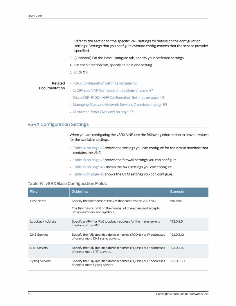
Refer to the section for the specific VNF settings for details on the configuration
settings. Settings that you configure override configurations that the service provider
specified.
3. (Optional) On the Base Configure tab, specify your preferred settings.
4. On each function tab, specify at least one setting.
5. ClickOK.
RelatedDocumentation
vSRX Configuration Settings on page 42•
• LxCIPtable VNF Configuration Settings on page 47
• Cisco CSR-1000v VNF Configuration Settings on page 49
• Managing Sites and Network Services Overview on page 53
• Customer Portal Overview on page 37
vSRX Configuration Settings
When you are configuring the vSRX VNF, use the following information to provide values
for the available settings:
• Table 14 on page 42 shows the settings you can configure for the virtual machine that
contains the VNF.
• Table 15 on page 43 shows the firewall settings you can configure.
• Table 16 on page 45 shows the NAT settings you can configure.
• Table 17 on page 45 shows the UTM settings you can configure.
Table 14: vSRX Base Configuration Fields
ExampleGuidelinesField
vm-vsrxSpecify the hostname of the VM that contains the vSRX VNF.
The field has no limit on the number of characters and acceptsletters, numbers, and symbols.
Host Name
192.0.2.5Specify an IPv4 or IPv6 loopback address for the managementinterface of the VM.
Loopback Address
192.0.2.10Specify the fully qualified domain names (FQDNs) or IP addressesof one or more DNS name servers.
DNS Servers
192.0.2.15Specify the fully qualified domain names (FQDNs) or IP addressesof one or more NTP servers.
NTP Servers
192.0.2.30Specify the fully qualified domain names (FQDNs) or IP addressesof one or more Syslog servers.
Syslog Servers
Copyright © 2016, Juniper Networks, Inc.42
User Guide
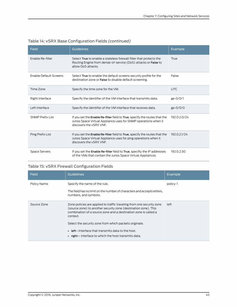
Table 14: vSRX Base Configuration Fields (continued)
ExampleGuidelinesField
TrueSelect True to enable a stateless firewall filter that protects theRouting Engine from denial-of-service (DoS) attacks or False toallow DoS attacks.
Enable Re-filter
FalseSelect True to enable the default screens security profile for thedestination zone or False to disable default screening.
Enable Default Screens
UTCSpecify the time zone for the VM.Time Zone
ge-0/0/1Specify the identifier of the VM interface that transmits data.Right Interface
ge-0/0/0Specify the identifier of the VM interface that receives data.Left Interface
192.0.2.0/24If you set the EnableRe-filter field to True, specify the routes that theJunos Space Virtual Appliance uses for SNMP operations when itdiscovers the vSRX VNF.
SNMP Prefix List
192.0.2.1/24If you set the EnableRe-filter field to True, specify the routes that theJunos Space Virtual Appliance uses for ping operations when itdiscovers the vSRX VNF.
Ping Prefix List
192.0.2.50If you set the Enable Re-filter field to True, specifiy the IP addressesof the VMs that contain the Junos Space Virtual Appliances.
Space Servers
Table 15: vSRX Firewall Configuration Fields
ExampleGuidelinesField
policy-1Specify the name of the rule.
The fieldhasno limit on thenumberof charactersandaccepts letters,numbers, and symbols.
Policy Name
leftZone policies are applied to traffic traveling from one security zone(source zone) to another security zone (destination zone). Thiscombination of a source zone and a destination zone is called acontext.
Select the security zone fromwhich packets originate.
• left—Interface that transmits data to the host.
• right— Interface to which the host transmits data.
Source Zone
43Copyright © 2016, Juniper Networks, Inc.
Chapter 7: Configuring Sites and Network Services
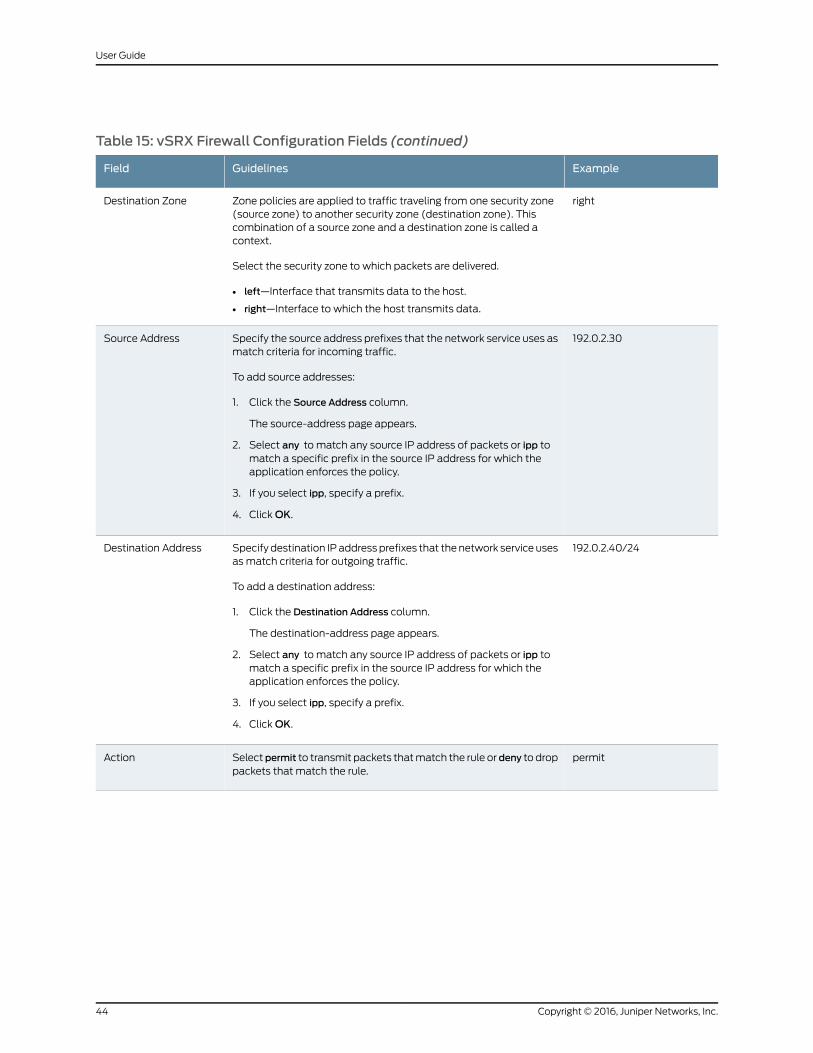
Table 15: vSRX Firewall Configuration Fields (continued)
ExampleGuidelinesField
rightZone policies are applied to traffic traveling from one security zone(source zone) to another security zone (destination zone). Thiscombination of a source zone and a destination zone is called acontext.
Select the security zone to which packets are delivered.
• left—Interface that transmits data to the host.
• right—Interface to which the host transmits data.
Destination Zone
192.0.2.30Specify the source address prefixes that the network service uses asmatch criteria for incoming traffic.
To add source addresses:
1. Click the Source Address column.
The source-address page appears.
2. Select any to match any source IP address of packets or ipp tomatch a specific prefix in the source IP address for which theapplication enforces the policy.
3. If you select ipp, specify a prefix.
4. ClickOK.
Source Address
192.0.2.40/24Specify destination IPaddressprefixes that thenetwork service usesas match criteria for outgoing traffic.
To add a destination address:
1. Click the Destination Address column.
The destination-address page appears.
2. Select any to match any source IP address of packets or ipp tomatch a specific prefix in the source IP address for which theapplication enforces the policy.
3. If you select ipp, specify a prefix.
4. ClickOK.
Destination Address
permitSelectpermit to transmit packets thatmatch the rule or deny to droppackets that match the rule.
Action
Copyright © 2016, Juniper Networks, Inc.44
User Guide

Table 15: vSRX Firewall Configuration Fields (continued)
ExampleGuidelinesField
• junos-tcp-any
• junos-udp-any
Specify theapplications towhich thepolicy applies. Theapplicationsare based on protocols and ports.
To specify applications:
1. Click the Application column.
The application page appears.
2. In the allowed_apps field, select any to match any application orapp to choose specific applications.
If you selectapp, pressandhold theCtrl keyandclick the requiredapplications in the drop-down list.
• junos-tcp-any
• junos-udp-any
• junos-ftp
• junos-http
• junos-https
• junos-icmp-all
• junos-icmp-ping
• junos-telnet
• junos-tftp
3. ClickOK.
Application
Table 16: vSRXNAT Configuration Fields
ExampleGuidelinesField
192.0.2.2/24Specify the source IP address of packets that the policy rules match.NAT Source Name
192.0.2.3/24Specify the destination IP address of packets that the policy rulesmatch.
NAT Destination Name
NAT policy settings—For information about the following policy settings, see the firewall policy settings in Table 15 on page 43.
• Policy Name
• Source Zone
• Destination Zone
• Source Address
• Destination Address
• Action
• Application
Table 17: vSRXUTMConfiguration Fields
ExampleGuidelinesField
TrueSelect True to check for viruses in application layer traffic against a virussignature database. Select False to disable checking for viruses.
Antivirus
45Copyright © 2016, Juniper Networks, Inc.
Chapter 7: Configuring Sites and Network Services
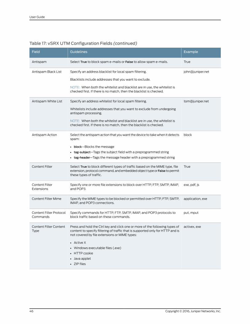
Table 17: vSRXUTMConfiguration Fields (continued)
ExampleGuidelinesField
TrueSelect True to block spam e-mails or False to allow spam e-mails.Antispam
[email protected] an address blacklist for local spam filtering.
Blacklists include addresses that you want to exclude.
NOTE: When both the whitelist and blacklist are in use, the whitelist ischecked first. If there is nomatch, then the blacklist is checked.
Antispam Black List
[email protected] an address whitelist for local spam filtering.
Whitelists include addresses that you want to exclude from undergoingantispam processing.
NOTE: When both the whitelist and blacklist are in use, the whitelist ischecked first. If there is nomatch, then the blacklist is checked.
AntispamWhite List
blockSelect theantispamaction that youwant thedevice to takewhen it detectsspam:
• block—Blocks the message
• tag-subject—Tags the subject field with a preprogrammed string
• tag-header—Tags themessage header with a preprogrammed string
Antispam Action
TrueSelect True to block different types of traffic based on the MIME type, fileextension,protocol command,andembeddedobject typeorFalse topermitthese types of traffic.
Content Filter
exe, pdf, jsSpecify one or more file extensions to block over HTTP, FTP, SMTP, IMAP,and POP3.
Content FilterExtensions
application, exeSpecify theMIME types to be blocked or permitted over HTTP, FTP, SMTP,IMAP, and POP3 connections.
Content Filter Mime
put, mputSpecify commands for HTTP, FTP, SMTP, IMAP, and POP3 protocols toblock traffic based on these commands.
Content Filter ProtocolCommands
activex, exePress and hold the Ctrl key and click one or more of the following types ofcontent to specify filtering of traffic that is supported only for HTTP and isnot covered by file extensions or MIME types:
• Active X
• Windows executable files (.exe)
• HTTP cookie
• Java applet
• ZIP files
Content Filter ContentType
Copyright © 2016, Juniper Networks, Inc.46
User Guide
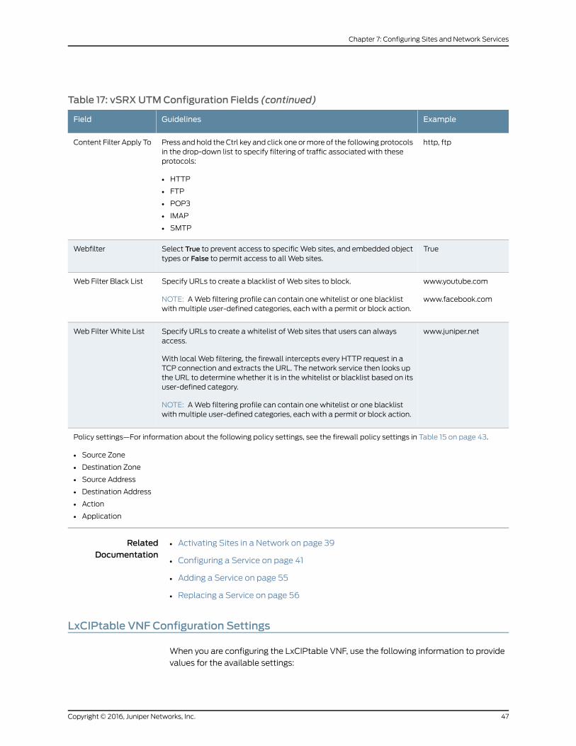
Table 17: vSRXUTMConfiguration Fields (continued)
ExampleGuidelinesField
http, ftpPress and hold theCtrl key and click one ormore of the following protocolsin the drop-down list to specify filtering of traffic associated with theseprotocols:
• HTTP
• FTP
• POP3
• IMAP
• SMTP
Content Filter Apply To
TrueSelect True to prevent access to specificWeb sites, and embedded objecttypes or False to permit access to all Web sites.
Webfilter
www.youtube.com
www.facebook.com
Specify URLs to create a blacklist of Web sites to block.
NOTE: AWeb filtering profile can contain one whitelist or one blacklistwith multiple user-defined categories, each with a permit or block action.
Web Filter Black List
www.juniper.netSpecify URLs to create a whitelist of Web sites that users can alwaysaccess.
With local Web filtering, the firewall intercepts every HTTP request in aTCP connection and extracts the URL. The network service then looks upthe URL to determine whether it is in the whitelist or blacklist based on itsuser-defined category.
NOTE: AWeb filtering profile can contain one whitelist or one blacklistwith multiple user-defined categories, each with a permit or block action.
Web Filter White List
Policy settings—For information about the following policy settings, see the firewall policy settings in Table 15 on page 43.
• Source Zone
• Destination Zone
• Source Address
• Destination Address
• Action
• Application
RelatedDocumentation
Activating Sites in a Network on page 39•
• Configuring a Service on page 41
• Adding a Service on page 55
• Replacing a Service on page 56
LxCIPtable VNF Configuration Settings
When you are configuring the LxCIPtable VNF, use the following information to provide
values for the available settings:
47Copyright © 2016, Juniper Networks, Inc.
Chapter 7: Configuring Sites and Network Services
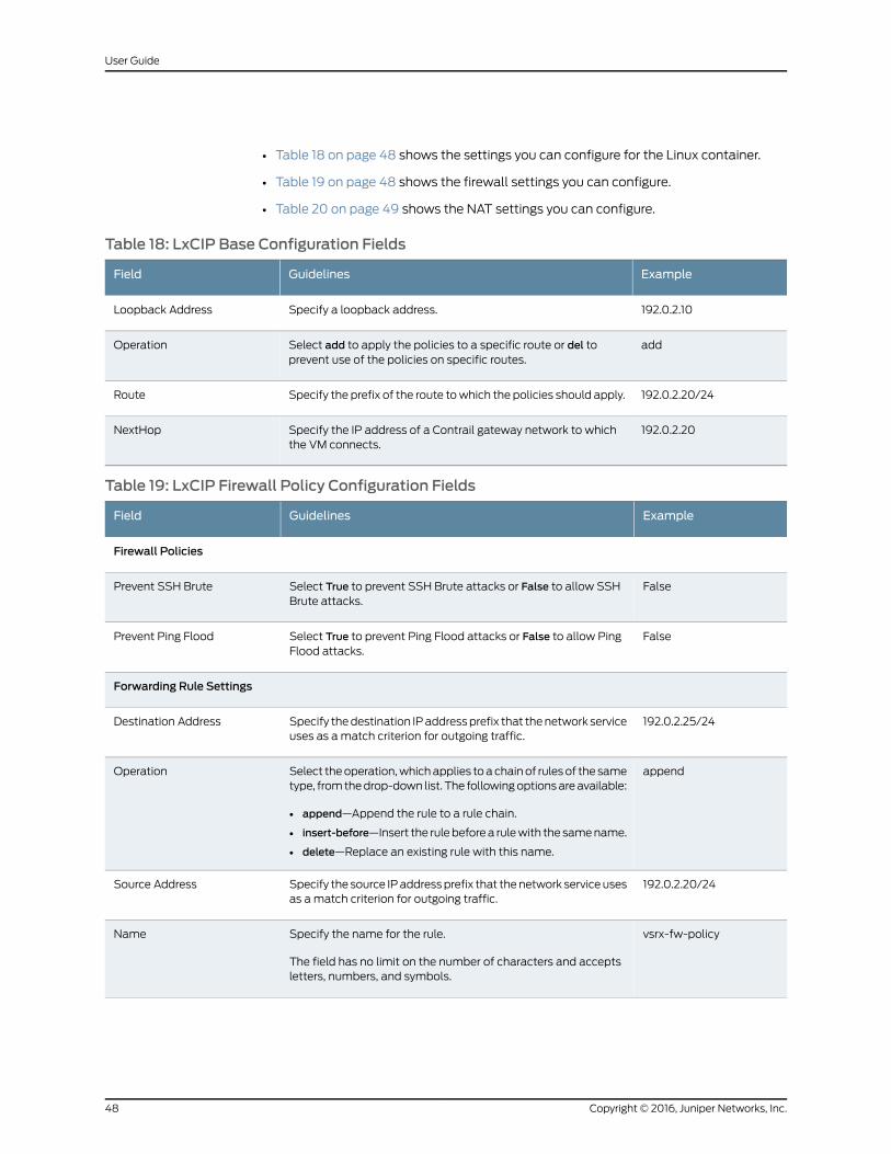
• Table 18 on page 48 shows the settings you can configure for the Linux container.
• Table 19 on page 48 shows the firewall settings you can configure.
• Table 20 on page 49 shows the NAT settings you can configure.
Table 18: LxCIP Base Configuration Fields
ExampleGuidelinesField
192.0.2.10Specify a loopback address.Loopback Address
addSelect add to apply the policies to a specific route or del toprevent use of the policies on specific routes.
Operation
192.0.2.20/24Specify the prefix of the route towhich the policies should apply.Route
192.0.2.20Specify the IP address of a Contrail gateway network to whichthe VM connects.
NextHop
Table 19: LxCIP Firewall Policy Configuration Fields
ExampleGuidelinesField
Firewall Policies
FalseSelect True to prevent SSH Brute attacks or False to allow SSHBrute attacks.
Prevent SSH Brute
FalseSelect True to prevent Ping Flood attacks or False to allow PingFlood attacks.
Prevent Ping Flood
Forwarding Rule Settings
192.0.2.25/24Specify thedestination IPaddressprefix that thenetwork serviceuses as amatch criterion for outgoing traffic.
Destination Address
appendSelect theoperation,whichapplies toachainof rulesof the sametype, fromthedrop-down list. The followingoptionsareavailable:
• append—Append the rule to a rule chain.
• insert-before—Insert the rulebeforea rulewith the samename.
• delete—Replace an existing rule with this name.
Operation
192.0.2.20/24Specify the source IPaddressprefix that thenetwork serviceusesas amatch criterion for outgoing traffic.
Source Address
vsrx-fw-policySpecify the name for the rule.
The field has no limit on the number of characters and acceptsletters, numbers, and symbols.
Name
Copyright © 2016, Juniper Networks, Inc.48
User Guide
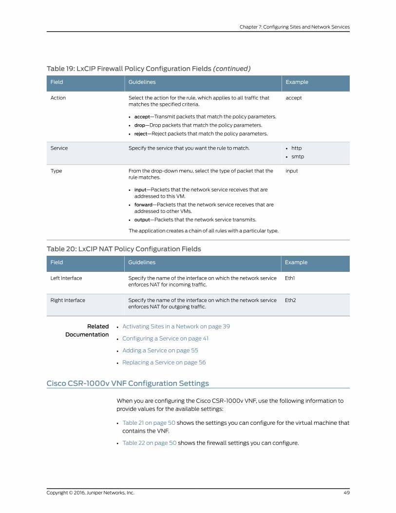
Table 19: LxCIP Firewall Policy Configuration Fields (continued)
ExampleGuidelinesField
acceptSelect the action for the rule, which applies to all traffic thatmatches the specified criteria.
• accept—Transmit packets that match the policy parameters.
• drop—Drop packets that match the policy parameters.
• reject—Reject packets that match the policy parameters.
Action
• http
• smtp
Specify the service that you want the rule to match.Service
inputFrom the drop-downmenu, select the type of packet that therule matches.
• input—Packets that the network service receives that areaddressed to this VM.
• forward—Packets that the network service receives that areaddressed to other VMs.
• output—Packets that the network service transmits.
The application creates a chain of all ruleswith a particular type.
Type
Table 20: LxCIP NAT Policy Configuration Fields
ExampleGuidelinesField
Eth1Specify the name of the interface on which the network serviceenforces NAT for incoming traffic.
Left Interface
Eth2Specify the name of the interface on which the network serviceenforces NAT for outgoing traffic.
Right Interface
RelatedDocumentation
Activating Sites in a Network on page 39•
• Configuring a Service on page 41
• Adding a Service on page 55
• Replacing a Service on page 56
Cisco CSR-1000v VNF Configuration Settings
When you are configuring the Cisco CSR-1000v VNF, use the following information to
provide values for the available settings:
• Table 21 on page 50 shows the settings you can configure for the virtual machine that
contains the VNF.
• Table 22 on page 50 shows the firewall settings you can configure.
49Copyright © 2016, Juniper Networks, Inc.
Chapter 7: Configuring Sites and Network Services
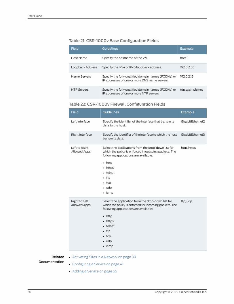
Table 21: CSR-1000v Base Configuration Fields
ExampleGuidelinesField
host1Specify the hostname of the VM.Host Name
192.0.2.50Specify the IPv4 or IPv6 loopback address.Loopback Address
192.0.2.15Specify the fully qualified domain names (FQDNs) orIP addresses of one or more DNS name servers.
Name Servers
ntp.example.netSpecify the fully qualified domain names (FQDNs) orIP addresses of one or more NTP servers.
NTP Servers
Table 22: CSR-1000v Firewall Configuration Fields
ExampleGuidelinesField
GigabitEthernet2Specify the identifier of the interface that transmitsdata to the host.
Left Interface
GigabitEthernet3Specify the identifier of the interface towhich thehosttransmits data.
Right Interface
http, httpsSelect the applications from the drop-down list forwhich the policy is enforced in outgoing packets. Thefollowing applications are available:
• http
• https
• telnet
• ftp
• tcp
• udp
• icmp
Left to RightAllowed Apps
ftp, udpSelect the application from the drop-down list forwhich the policy is enforced for incoming packets. Thefollowing applications are available:
• http
• https
• telnet
• ftp
• tcp
• udp
• icmp
Right to LeftAllowed Apps
RelatedDocumentation
• Activating Sites in a Network on page 39
• Configuring a Service on page 41
• Adding a Service on page 55
Copyright © 2016, Juniper Networks, Inc.50
User Guide
• Replacing a Service on page 56
51Copyright © 2016, Juniper Networks, Inc.
Chapter 7: Configuring Sites and Network Services

Copyright © 2016, Juniper Networks, Inc.52
User Guide
CHAPTER 8
Managing Sites and Network Services
• Managing Sites and Network Services Overview on page 53
• Monitoring a Service on page 54
• Deactivating a Site on page 54
• Adding a Service on page 55
• Replacing a Service on page 56
• Deactivating and Reactivating a Service on page 56
• Removing a Service on page 57
Managing Sites and Network Services Overview
After you have activated services and sites with the wizard, the Monitor page appears
displaying the VPNServices view,which shows the topology of sites and services relative
to theVPN.This page showsa topologyof theactive sites in thenetwork and thenetwork
serviceson the links. If the serviceprovider configuredyour network toallowdirect Internet
access fromoneormore sites, click the Internet Services tab to view the topology of sites
and services relative to the Internet.
From the Monitor page, you can:
• Manage, configure, andmonitor network services on connections.
• Deactivate sites.
• Access the wizard to activate other sites.
Only active sites appear on theMonitor page. You can addmore sites through thewizard
by clicking Add Sites in the bottom left of the Monitor page.
A network service on a link appears as a hexagon. A gray hexagon indicates that the
service is disabled, and a blue hexagon indicates that the service is enabled. When you
click a service hexagon, it enlarges and small circles appear on several vertices of the
hexagon. If you hover over a circle on one of these vertices, you see the action that you
can performwhen you click the vertex. The circles that appear on the vertices depend
on the state of the service; only circles for actions that you can currently perform are
visible. For example, the Enable vertex circle is visible only if the service is disabled, and
not visible when the service is enabled.
53Copyright © 2016, Juniper Networks, Inc.
Available network services appear in the bar below the topology graphic, at the bottom
of the page.
RelatedDocumentation
Deactivating a Site on page 54•
• Activating Sites in a Network on page 39
• Adding a Service on page 55
• Replacing a Service on page 56
• Deactivating and Reactivating a Service on page 56
• Removing a Service on page 57
• Configuring a Service on page 41
Monitoring a Service
Use theMonitor page to configure a network service if you did not configure the network
service when you activated a site or if you want to reconfigure the service.
Tomonitor a service:
1. Click the service icon on the connection.
2. ClickMonitor on the bottom right vertex of the hexagon.
The Status page appears.
• Uptimestatus indicates thepercentageof time the servicehasbeenavailableduring
the displayed elapsed time since you activated the service.
• Bandwidth status shows the rate of traffic for the service with the following
breakdown:
• Left—Interface that transmits traffic to the service
• Right—Interface to which the service transmits traffic
• Input—Rate of traffic arriving at an interface
• Output—Rate of traffic leaving at an interface
• Sessions status shows the number of end users currently using the service at the
site.
3. Click Cancel to hide the Status page.
RelatedDocumentation
Managing Sites and Network Services Overview on page 53•
Deactivating a Site
Use the Monitor page to deactivate a site that you added with the wizard.
Copyright © 2016, Juniper Networks, Inc.54
User Guide
To deactivate a site in the network:
1. Hover over the site in the left navigation pane.
A blue close button appears at the end of the site.
2. Click the blue close button for the site.
The site is deactivated.
RelatedDocumentation
Managing Sites and Network Services Overview on page 53•
• Activating Sites in a Network on page 39
Adding a Service
You can add a network service on a connection between a site and the VPNwhen you
activate the site in the network. Use the Monitor page to add a network service if you did
not do so when you activated the site.
To add a service on a connection:
1. In the bar below the topology graphic, click the network service that you want to use.
The cursor changes to display the service icon.
2. Click the connection on which you want to use the network service.
The Service page appears.
Refer to the section for the specific VNF settings for details on the configuration
settings. Settings that you configure override configurations that the service provider
specified.
3. (Optional) On the Base Configure tab, specify your preferred settings.
4. On each function tab, specify at least one setting.
5. ClickOK.
A gray icon for the service appears on the connection.
6. Click the service icon on the connection.
7. Click Enable Service on themiddle left vertex of the hexagon.
The new service starts on the connection, and is displayed as a blue icon on the
connection when it becomes active.
RelatedDocumentation
vSRX Configuration Settings on page 42•
• LxCIPtable VNF Configuration Settings on page 47
• Cisco CSR-1000v VNF Configuration Settings on page 49
• Managing Sites and Network Services Overview on page 53
• Replacing a Service on page 56
55Copyright © 2016, Juniper Networks, Inc.
Chapter 8: Managing Sites and Network Services
• Deactivating and Reactivating a Service on page 56
• Removing a Service on page 57
Replacing a Service
You activate network services to connections between sites and the VPNwhen you
activate a site in the network.When you view the network topology on theMonitor page,
you canmanage existing sites and services and activate additional services.
To replace a service on a connection:
1. In the bar below the topology graphic, click the network service that you want to use.
The cursor changes to display the service icon.
2. Click the connection on which you want to use the network service.
The Service page appears.
Refer to the section for the specific VNF settings for details on the configuration
settings. Settings that you configure override configurations that the service provider
specified.
3. (Optional) On the Base Configure tab, specify your preferred settings.
4. On each function tab, specify at least one setting.
5. ClickOK.
A gray icon for the service appears on the connection.
RelatedDocumentation
vSRX Configuration Settings on page 42•
• LxCIPtable VNF Configuration Settings on page 47
• Cisco CSR-1000v VNF Configuration Settings on page 49
• Managing Sites and Network Services Overview on page 53
• Deactivating and Reactivating a Service on page 56
• Removing a Service on page 57
Deactivating and Reactivating a Service
You can select and activate a network service for a site when you activate the site. Use
the Monitor page to deactivate and reactivate a network service.
Copyright © 2016, Juniper Networks, Inc.56
User Guide
To deactivate or activate a service for a site:
1. Click the service icon on the connection.
2. Click Disable Service on the top right vertex of the hexagon or Enable Service on the
middle left vertex of the hexagon.
A page requesting confirmation for the action appears.
3. Click Yes to confirm that you want to deactivate or activate the service.
Thecolor of the service iconchanges fromblue tograywhenyoudeactivate the service
and from gray to blue when you activate the service.
RelatedDocumentation
Managing Sites and Network Services Overview on page 53•
• Adding a Service on page 55
• Replacing a Service on page 56
• Removing a Service on page 57
• Activating Sites in a Network on page 39
Removing a Service
Use the Monitor page to remove a network service on a connection between a site and
the VPN.
To remove a service from a connection:
1. Disable the service.
2. Click the service icon on the connection.
3. Click Remove Service on the top left vertex of the hexagon.
A page requesting confirmation for the deletion appears.
4. Click Yes to confirm that you want to delete the design.
The service icon disappears.
RelatedDocumentation
• Managing Sites and Network Services Overview on page 53
• Deactivating and Reactivating a Service on page 56
• Adding a Service on page 55
• Replacing a Service on page 56
57Copyright © 2016, Juniper Networks, Inc.
Chapter 8: Managing Sites and Network Services

Copyright © 2016, Juniper Networks, Inc.58
User Guide
PART 4
Network Service Designer
• Network Service Designer introduction on page 61
• Creating Network Services on page 65
• Configuring Network Services on page 73
• Managing Requests and Designs on page 83
59Copyright © 2016, Juniper Networks, Inc.

Copyright © 2016, Juniper Networks, Inc.60
User Guide
CHAPTER 9
Network Service Designer introduction
• Network Service Designer Overview on page 61
• Accessing Network Service Designer on page 61
• Getting Started with Network Service Designer on page 62
• Network Services and Service Chains Overview on page 62
Network Service Designer Overview
Network Service Designer is a visual design tool that you use to create andmanage
network services for Juniper Networks Cloud CPE Centralized Deployment Model. With
Network Service Designer you can:
• Create requests for new network services.
• Design customized network services for your customers.
• Design new standard network services that you can offer to all your customers.
• Update existing network services.
• Publish services to the network service catalog.
• Manage network services that you are designing or have published to the network
catalog.
• Configure somebasicparameters for theVNFsused inanetwork serviceand thevirtual
containers in which the VNFs reside.
RelatedDocumentation
Network Services and Service Chains Overview on page 62•
• Getting Started with Network Service Designer on page 62
Accessing Network Service Designer
To start Network Service Designer:
1. Reviewthekeystoneusernameandpassword that youdefined forContrailOpenStack.
You can view these settings on the Contrail Configure and Control Node in the files
/etc/contrail/keystonerc and /etc/contrail/openstackrc.
61Copyright © 2016, Juniper Networks, Inc.
2. Using a web browser, access the URL for Network Services Designer.
For example, if the IP address of the VM on which Network Service Designer resides
is 192.0.2.1, the URL is http://192.0.2.1/nsd-ui/index.html.
3. Log in with the keystone username and password that you specified for Contrail
OpenStack.
RelatedDocumentation
Network Service Designer Overview on page 61•
Getting Started with Network Service Designer
When you log in to Network Service Designer, the Requests page displays open requests
for new network services. Use this page to start designs for those open requests and to
create new requests for network services.
Before You Begin
• Learn about network services and service chains. See “Network Services and Service
Chains Overview” on page 62.
Creating a Network Service
You create a network service as follows:
1. Create a request for a network service.
2. Design a service chain—a structure that details specific VNFs, a performance
specification, and defined ingress and egress points for the network service.
3. Publish the final design—the network service—to the network service catalog.
RelatedDocumentation
Network Services and Service Chains Overview on page 62•
• Creating Requests for Network Services on page 65
• Designing Service Chains for Network Services on page 67
• Managing Requests for Network Services on page 83
• Managing Service Chain Designs on page 84
Network Services and Service Chains Overview
The terms network service and service chain are sometimes used interchangeably, but
they are not the same; you need to understand the difference between them:
• A network service is a final product offered to end users with a full description of its
functionality and specified performance.
Administrators deploy network services between two locations in a virtual network,
so that traffic traveling in a specific direction on that link is subject to action from that
Copyright © 2016, Juniper Networks, Inc.62
User Guide
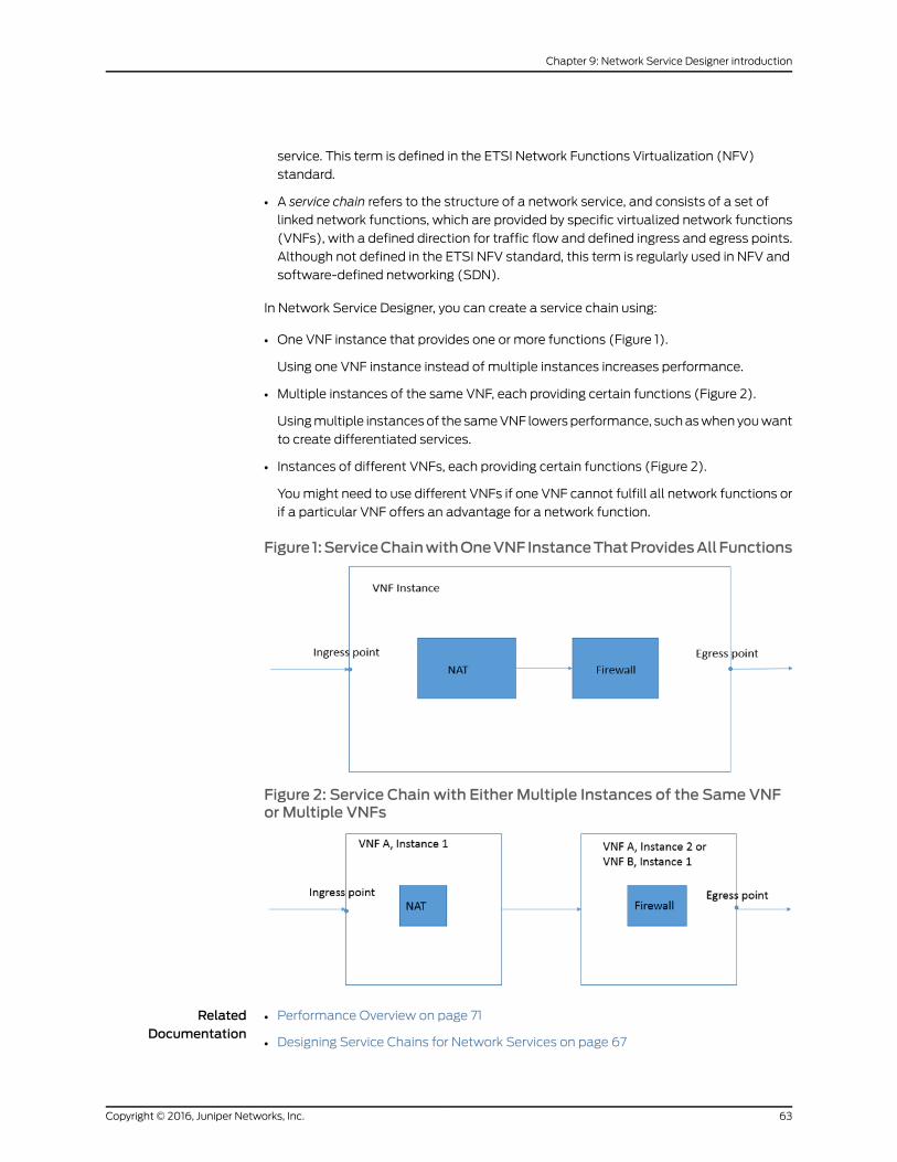
service. This term is defined in the ETSI Network Functions Virtualization (NFV)
standard.
• A service chain refers to the structure of a network service, and consists of a set of
linked network functions, which are provided by specific virtualized network functions
(VNFs), with a defined direction for traffic flow and defined ingress and egress points.
Although not defined in the ETSI NFV standard, this term is regularly used in NFV and
software-defined networking (SDN).
In Network Service Designer, you can create a service chain using:
• One VNF instance that provides one or more functions (Figure 1).
Using one VNF instance instead of multiple instances increases performance.
• Multiple instances of the same VNF, each providing certain functions (Figure 2).
Usingmultiple instancesof the sameVNF lowersperformance, suchaswhen youwant
to create differentiated services.
• Instances of different VNFs, each providing certain functions (Figure 2).
Youmight need to use different VNFs if one VNF cannot fulfill all network functions or
if a particular VNF offers an advantage for a network function.
Figure 1:ServiceChainwithOneVNFInstanceThatProvidesAllFunctions
Figure 2: Service Chain with Either Multiple Instances of the Same VNFor Multiple VNFs
RelatedDocumentation
• Performance Overview on page 71
• Designing Service Chains for Network Services on page 67
63Copyright © 2016, Juniper Networks, Inc.
Chapter 9: Network Service Designer introduction
• Defining Ingress and Egress Points for a Service Chain on page 69
Copyright © 2016, Juniper Networks, Inc.64
User Guide
CHAPTER 10
Creating Network Services
• Creating Requests for Network Services on page 65
• Designing Service Chains for Network Services on page 67
• Defining Ingress and Egress Points for a Service Chain on page 69
• Connecting VNFs in a Service Chain on page 69
• VNF Overview on page 70
• Viewing Information About VNFs on page 70
• Performance Overview on page 71
• Meeting Performance Goals on page 72
Creating Requests for Network Services
When you create a request for a network service, you define the requirements for the
service, including the required network functions and the performance.
Before You Begin
• Determinewhich functions to include in the network service and the order inwhich you
want the functions to be applied.
• Understand performance specifications for network services. See “Performance
Overview” on page 71.
To create a request for a network service:
1. Click HOME in the toolbar and Requests in the left navigation bar.
2. Click NEWREQUEST at the bottom right of the page.
A page in which you specify information about the request appears.
3. In the Name field, specify the name for the request.
TheName field accepts up to 60 characters, including letters, numbers, and symbols.
4. (Optional) If the request is urgent, select the Priority Request check box.
5. (Optional) In the Customer Name (Optional) field, specify a customer.
The Customer Name field accepts up to 60 characters, including letters, numbers,
and symbols.
65Copyright © 2016, Juniper Networks, Inc.
6. In the Description field, specify a description for the service.
The Description field accepts up to 500 characters, including letters, numbers, and
symbols.
7. (Optional) In the Requirements field, specify the requirements for the request.
The Description field accepts up to 1000 characters, including letters, numbers, and
symbols.
8. (Optional) Click Select Files, navigate to a file you want to attach, and clickOpen.
The file is downloaded to the Attachments (Optional) field.
9. Click NEXT.
The Build page appears, displaying the Goals pane, the Functional Service Design
area, and the Function Palette.
10. Drag and drop the network functions in the required order from the Function Palette
to the Functional Service Design area.
• NetworkServiceDesigner automatically connects thenetwork functions in theorder
that you place them in the design area.
• You can insert a function between two functions already on the design pane.
• If youmake an error, you can right-click a component in the design area and delete
the component.
11. (Optional) In the Goals pane, click Add Goal.
The New Goal window appears.
BEST PRACTICE: Adding one ormore goals to the request enables you totrack performance of those parameters when you design a service chainfor the request. Although adding goals is not mandatory, we recommendthat you do so.
12. From the Typemenu, select a goal for the network service.
You can add goals in any order.
13. In the Goal Value field, specify the target value for this goal.
14. (Optional) In the Acceptable Value field, specify the value that you can accept if the
target value is not available.
15. (Optional) In the Must Value field, specify the minimum value for this goal.
16. In the Unit field (for the Bandwidth and Latency types only), select the units for the
goal.
17. Click SAVE.
18. (Optional) Repeat Step 12 through Step 17 to add the other goals.
19. Click NEXT.
Copyright © 2016, Juniper Networks, Inc.66
User Guide
A page appears that displays the details you entered for the request.
20.Review the details andmake corrections if necessary, using the PREVIOUS andNEXT
options to navigate through the pages.
21. When you are satisfied with the information, click CREATE.
The request for the network service design appears on the Requests page.
RelatedDocumentation
Network Services and Service Chains Overview on page 62•
• Performance Overview on page 71
• Designing Service Chains for Network Services on page 67
Designing Service Chains for Network Services
When you save a request it appears on the Requests page. You can then design a service
chain to fulfill the request, using VNFs in the Vendor catalog to provide the requested
network functions.
Before You Begin
• Understand the structure of a network service. See “Network Services and Service
Chains Overview” on page 62.
• Review the VNFs in the Vendor catalog to determinewhich VNFs to use in your design.
See “Viewing Information About VNFs” on page 70.
• Learn how to add ingress and egress points to a service chain. See “Defining Ingress
and Egress Points for a Service Chain” on page 69.
• LearnhowtoconnectVNFs inaservicechain.See “ConnectingVNFs inaServiceChain”
on page 69.
• Learn how to track the performance of your design against the requested performance
goals. See “Meeting Performance Goals” on page 72.
• Learnhowtoconfigurenetworkservices.See “ConfiguringNetworkServices”onpage73.
Designing a Service Chain for a Network Service
To design a service chain:
1. Click HOME in the toolbar and Requests in the left navigation bar.
The Requests page appears, displaying requests created when you published service
chain designs.
2. Hover over the request.
A menu appears in the bottom right of the request.
3. Click BEGIN.
If the help overlay is visible, click Close Help.
67Copyright © 2016, Juniper Networks, Inc.
Chapter 10: Creating Network Services
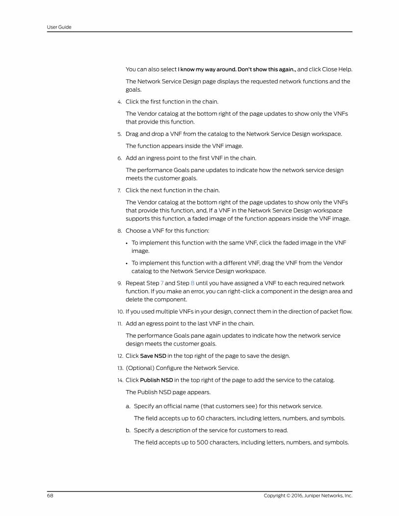
You can also select I knowmywayaround. Don’t show this again., and click Close Help.
The Network Service Design page displays the requested network functions and the
goals.
4. Click the first function in the chain.
The Vendor catalog at the bottom right of the page updates to show only the VNFs
that provide this function.
5. Drag and drop a VNF from the catalog to the Network Service Design workspace.
The function appears inside the VNF image.
6. Add an ingress point to the first VNF in the chain.
The performance Goals pane updates to indicate how the network service design
meets the customer goals.
7. Click the next function in the chain.
The Vendor catalog at the bottom right of the page updates to show only the VNFs
that provide this function, and, If a VNF in the Network Service Design workspace
supports this function, a faded image of the function appears inside the VNF image.
8. Choose a VNF for this function:
• To implement this function with the same VNF, click the faded image in the VNF
image.
• To implement this function with a different VNF, drag the VNF from the Vendor
catalog to the Network Service Design workspace.
9. Repeat Step 7 and Step 8 until you have assigned a VNF to each required network
function. If youmake an error, you can right-click a component in the design area and
delete the component.
10. If you usedmultiple VNFs in your design, connect them in the direction of packet flow.
11. Add an egress point to the last VNF in the chain.
The performance Goals pane again updates to indicate how the network service
design meets the customer goals.
12. Click Save NSD in the top right of the page to save the design.
13. (Optional) Configure the Network Service.
14. Click Publish NSD in the top right of the page to add the service to the catalog.
The Publish NSD page appears.
a. Specify an official name (that customers see) for this network service.
The field accepts up to 60 characters, including letters, numbers, and symbols.
b. Specify a description of the service for customers to read.
The field accepts up to 500 characters, including letters, numbers, and symbols.
Copyright © 2016, Juniper Networks, Inc.68
User Guide
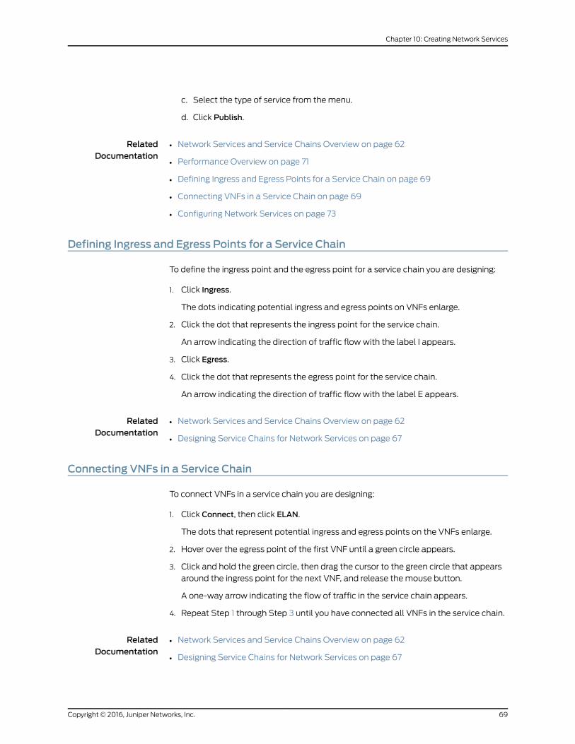
c. Select the type of service from themenu.
d. Click Publish.
RelatedDocumentation
Network Services and Service Chains Overview on page 62•
• Performance Overview on page 71
• Defining Ingress and Egress Points for a Service Chain on page 69
• Connecting VNFs in a Service Chain on page 69
• Configuring Network Services on page 73
Defining Ingress and Egress Points for a Service Chain
To define the ingress point and the egress point for a service chain you are designing:
1. Click Ingress.
The dots indicating potential ingress and egress points on VNFs enlarge.
2. Click the dot that represents the ingress point for the service chain.
An arrow indicating the direction of traffic flow with the label I appears.
3. Click Egress.
4. Click the dot that represents the egress point for the service chain.
An arrow indicating the direction of traffic flow with the label E appears.
RelatedDocumentation
Network Services and Service Chains Overview on page 62•
• Designing Service Chains for Network Services on page 67
Connecting VNFs in a Service Chain
To connect VNFs in a service chain you are designing:
1. Click Connect, then click ELAN.
The dots that represent potential ingress and egress points on the VNFs enlarge.
2. Hover over the egress point of the first VNF until a green circle appears.
3. Click and hold the green circle, then drag the cursor to the green circle that appears
around the ingress point for the next VNF, and release the mouse button.
A one-way arrow indicating the flow of traffic in the service chain appears.
4. Repeat Step 1 through Step 3 until you have connected all VNFs in the service chain.
RelatedDocumentation
Network Services and Service Chains Overview on page 62•
• Designing Service Chains for Network Services on page 67
69Copyright © 2016, Juniper Networks, Inc.
Chapter 10: Creating Network Services
VNFOverview
Avirtualizednetwork function (VNF) is a software application used inNetwork Functions
Virtualization(NFV) thathaswelldefined interfaces, andprovidesoneormorecomponent
networking functions in a well defined way. For example, a security VNFmight provide
Network Address Translation (NAT) and Firewall component functions.
For the Cloud CPE Centralized Deployment Model, you design network services for
enterprise customers based on VNFs. Each VNF used in the network service is deployed
in itsownvirtualmachine(VM).VNFs inanetworkserviceorcomponentnetwork functions
in a VNF are connected by the underlying Contrail software.
Vendors specify the following required resources for a VNF:
• Number of virtual CPUs
• Virtual memory (MB)
• Virtual disk capacity (MB)
TheCloudCPECentralizedDeploymentModel supports a rangeof JuniperNetworks and
third-partyVNFs. Vendors canprovidemultiple versionsof aVNF that offer differentiated
performance. You can see available VNFs and their specifications and resource
requirements in the Vendor catalog of the Network Service Designer tool.
RelatedDocumentation
Performance Overview on page 71•
• Viewing Information About VNFs on page 70
• Designing Service Chains for Network Services on page 67
Viewing Information About VNFs
You can view performance specifications, required resources, and component network
functions for each VNF in the Vendor catalog. Reviewing this information can help you
to determine which VNF to use when you are designing a network service.
Before You Begin
• Learn about VNFs. See “VNF Overview” on page 70.
• Understand performance parameters. See “Performance Overview” on page 71.
Viewing Information for a Specific VNF
Copyright © 2016, Juniper Networks, Inc.70
User Guide
To view information for a specific VNF:
1. Click the network function in the Vendor catalog.
The information window for the network function appears, displaying the following
information on the Details tab:
• Agraphical representationof thecompletenetwork functionwith ingressandegress
points.
• A list of resources required for the network function.
2. Click Functions.
You see the category of the network function, such as security, and the component
functions, such as NAT and Firewall.
3. Click Service Chains to display:
• A list of the potential internal service chains (allowed combinations of component
functions) for this network function.
Lines without arrows connecting component functions in an internal service chain
indicate that the order of the functions does not matter.
• The performance specification for each internal service chain.
4. Close the VNF information window by clicking anywhere outside the window.
RelatedDocumentation
VNF Overview on page 70•
• Performance Overview on page 71
Performance Overview
The following parameters define the performance of a network service, a virtualized
network function (VNF), and the component functions of a VNF:
• Bandwidth (Mbps or Gbps)—Data rate for the function or service.
• Latency (ms or ns)—Time a packet takes to traverse the function or service.
• Bandwidth (Mbps or Gbps)—Data rate for the function or service.
Vendors provide specified values for these parameters for a VNF and for each allowed
combinationof components in theVNF(internal servicechain).Youcanviewthespecified
values in the Vendor catalog.
Network Service Designer evaluates the aggregate performance of the design against
the goals in the request and displays the information in the Goals pane.
RelatedDocumentation
VNF Overview on page 70•
• Meeting Performance Goals on page 72
• Viewing Information About VNFs on page 70
71Copyright © 2016, Juniper Networks, Inc.
Chapter 10: Creating Network Services
• Designing Service Chains for Network Services on page 67
Meeting Performance Goals
Network Service Designer provides comprehensive information about performance of
VNFsand their componentnetwork function in theVNFcatalog.NetworkServiceDesigner
also tracks the aggregate performance of a network service that you are designing and
saves this information to the network service catalog.
Minimizing the number of VNFs and VNF instances in a service chain optimizes the
performance of a network service. For example, using one VNF instance for both NAT
and firewall functions provides higher performance than using either separate instances
of the same VNF or different VNFs to provide the functions.
You specify performance goals for the service when you create a request for a network
service. When you are designing a service chain, you evaluate the performance of your
design against the requested goals.
Before You Begin
• Understand the definition of performance for a network service. See “Performance
Overview” on page 71.
• Review the performance specification of VNFs in the Vendor catalog. See “Viewing
Information About VNFs” on page 70.
Monitoring Performance of a Network Service Design
Youmonitor the performance of a service that you are designing as follows:
1. Click the right arrow in the Goals pane to view the performance goals.
2. Add an ingress point to the first VNF in the service chain immediately after you assign
that VNF to the first network function.
3. Monitor the values in the Goals pane as you design your service chain.
RelatedDocumentation
• Network Services and Service Chains Overview on page 62
• Performance Overview on page 71
• Designing Service Chains for Network Services on page 67
• Defining Ingress and Egress Points for a Service Chain on page 69
Copyright © 2016, Juniper Networks, Inc.72
User Guide
CHAPTER 11
Configuring Network Services
• Configuring Network Services on page 73
• vSRX Configuration Settings on page 74
• LxCIPtable VNF Configuration Settings on page 79
• Cisco CSR-1000v VNF Configuration Settings on page 81
Configuring Network Services
When you are designing a service chain or after you have designed a service chain, you
can configure settings for the VNFs in the chain:
• The virtual container in which the VNF resides.
• The network functions, such as NAT or firewall, that the VNF provides.
The settings that you can configure depend on the actual VNF. Manual configurations
areoptional andoverrideautomatic configurations specifiedby theCloudCPECentralized
DeploymentModeldeploymentscript, otherContrail ServiceOrchestrationcomponents,
or default LxCIPTable VNF settings.
Before You Begin
• Review the configuration settings for the VNFs that you want to configure.
To configure the network service:
1. View the service chain design on the BUILD page.
If the design is not currently visible on the BUILD page:
a. Click HOME in the toolbar and Designs in the left navigation bar.
The list of saved and published designs appears.
b. Click Edit from themenu at the end of the row for the network service you want to
configure.
The BUILD page appears, displaying the service chain design.
2. Click Function Configuration at the right of the BUILD page.
73Copyright © 2016, Juniper Networks, Inc.
The Service page appears, displaying the VNFs in the service chain and the Base
Configure tab for the first VNF in the Functional Service Design workspace.
3. Specify the settings on the Base Configure tab.
This action configures the VM in which the VNF resides.
BEST PRACTICE: Complete all the settings on the Base Configure tab tooptimize the Cloud CPE Centralized Deployment Model. End users cansee these settings in Customer Portal and should not override them.
4. (Optional) Specify settings on the other tabs for this VNF to customize a particular
function such as Network Address Translation (NAT).
End users can customize their own services with these settings in Customer Portal.
Settings that end users specify in Customer Portal override conflicting settings that
you specify in Network Service Designer.
5. Click the next VNF icon in the Configuration page.
6. Repeat Step 3 and Step 4.
7. Repeat Steps 5 through 7 for each VNF in the chain.
8. ClickOK.
The Service page closes.
RelatedDocumentation
vSRX Configuration Settings on page 74•
• LxCIPtable VNF Configuration Settings on page 79
• Cisco CSR-1000v VNF Configuration Settings on page 81
vSRX Configuration Settings
When you are configuring the vSRX VNF, use the following information to provide values
for the available settings:
• Table 14 on page 42 shows the settings you can configure for the virtual machine that
contains the VNF.
• Table 15 on page 43 shows the firewall settings you can configure.
• Table 16 on page 45 shows the NAT settings you can configure.
• Table 17 on page 45 shows the UTM settings you can configure.
Copyright © 2016, Juniper Networks, Inc.74
User Guide
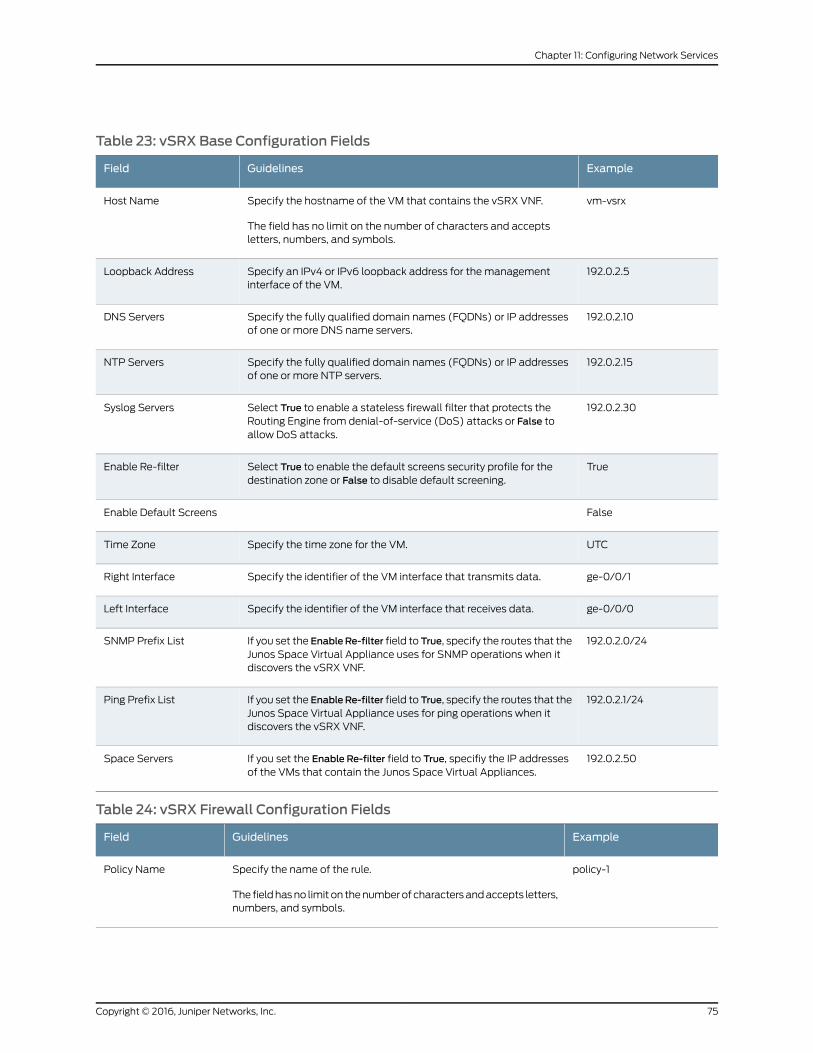
Table 23: vSRX Base Configuration Fields
ExampleGuidelinesField
vm-vsrxSpecify the hostname of the VM that contains the vSRX VNF.
The field has no limit on the number of characters and acceptsletters, numbers, and symbols.
Host Name
192.0.2.5Specify an IPv4 or IPv6 loopback address for the managementinterface of the VM.
Loopback Address
192.0.2.10Specify the fully qualified domain names (FQDNs) or IP addressesof one or more DNS name servers.
DNS Servers
192.0.2.15Specify the fully qualified domain names (FQDNs) or IP addressesof one or more NTP servers.
NTP Servers
192.0.2.30Select True to enable a stateless firewall filter that protects theRouting Engine from denial-of-service (DoS) attacks or False toallow DoS attacks.
Syslog Servers
TrueSelect True to enable the default screens security profile for thedestination zone or False to disable default screening.
Enable Re-filter
FalseEnable Default Screens
UTCSpecify the time zone for the VM.Time Zone
ge-0/0/1Specify the identifier of the VM interface that transmits data.Right Interface
ge-0/0/0Specify the identifier of the VM interface that receives data.Left Interface
192.0.2.0/24If you set the EnableRe-filter field to True, specify the routes that theJunos Space Virtual Appliance uses for SNMP operations when itdiscovers the vSRX VNF.
SNMP Prefix List
192.0.2.1/24If you set the EnableRe-filter field to True, specify the routes that theJunos Space Virtual Appliance uses for ping operations when itdiscovers the vSRX VNF.
Ping Prefix List
192.0.2.50If you set the Enable Re-filter field to True, specifiy the IP addressesof the VMs that contain the Junos Space Virtual Appliances.
Space Servers
Table 24: vSRX Firewall Configuration Fields
ExampleGuidelinesField
policy-1Specify the name of the rule.
The fieldhasno limit on thenumberof charactersandaccepts letters,numbers, and symbols.
Policy Name
75Copyright © 2016, Juniper Networks, Inc.
Chapter 11: Configuring Network Services
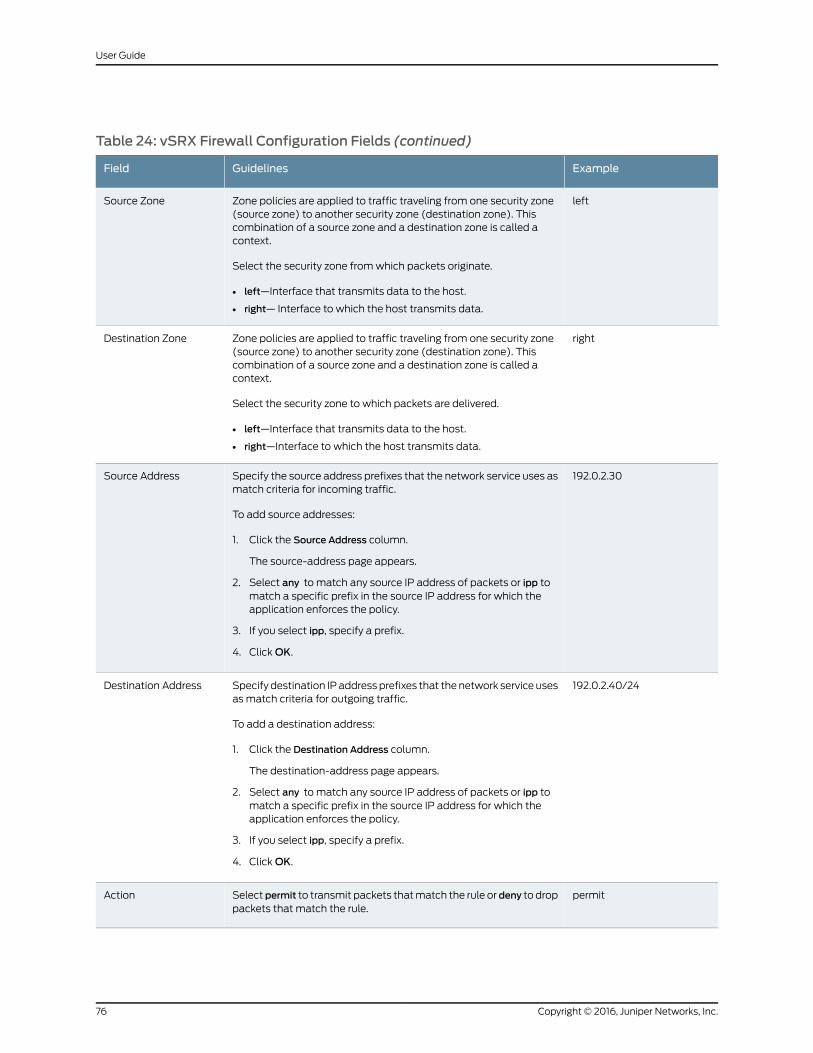
Table 24: vSRX Firewall Configuration Fields (continued)
ExampleGuidelinesField
leftZone policies are applied to traffic traveling from one security zone(source zone) to another security zone (destination zone). Thiscombination of a source zone and a destination zone is called acontext.
Select the security zone fromwhich packets originate.
• left—Interface that transmits data to the host.
• right— Interface to which the host transmits data.
Source Zone
rightZone policies are applied to traffic traveling from one security zone(source zone) to another security zone (destination zone). Thiscombination of a source zone and a destination zone is called acontext.
Select the security zone to which packets are delivered.
• left—Interface that transmits data to the host.
• right—Interface to which the host transmits data.
Destination Zone
192.0.2.30Specify the source address prefixes that the network service uses asmatch criteria for incoming traffic.
To add source addresses:
1. Click the Source Address column.
The source-address page appears.
2. Select any to match any source IP address of packets or ipp tomatch a specific prefix in the source IP address for which theapplication enforces the policy.
3. If you select ipp, specify a prefix.
4. ClickOK.
Source Address
192.0.2.40/24Specify destination IPaddressprefixes that thenetwork service usesas match criteria for outgoing traffic.
To add a destination address:
1. Click the Destination Address column.
The destination-address page appears.
2. Select any to match any source IP address of packets or ipp tomatch a specific prefix in the source IP address for which theapplication enforces the policy.
3. If you select ipp, specify a prefix.
4. ClickOK.
Destination Address
permitSelectpermit to transmit packets thatmatch the rule or deny to droppackets that match the rule.
Action
Copyright © 2016, Juniper Networks, Inc.76
User Guide
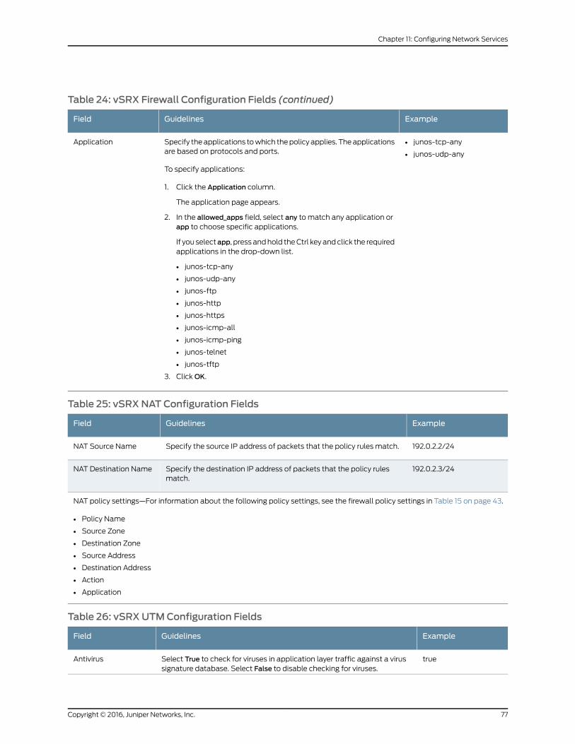
Table 24: vSRX Firewall Configuration Fields (continued)
ExampleGuidelinesField
• junos-tcp-any
• junos-udp-any
Specify theapplications towhich thepolicy applies. Theapplicationsare based on protocols and ports.
To specify applications:
1. Click the Application column.
The application page appears.
2. In the allowed_apps field, select any to match any application orapp to choose specific applications.
If you selectapp, pressandhold theCtrl keyandclick the requiredapplications in the drop-down list.
• junos-tcp-any
• junos-udp-any
• junos-ftp
• junos-http
• junos-https
• junos-icmp-all
• junos-icmp-ping
• junos-telnet
• junos-tftp
3. ClickOK.
Application
Table 25: vSRXNAT Configuration Fields
ExampleGuidelinesField
192.0.2.2/24Specify the source IP address of packets that the policy rules match.NAT Source Name
192.0.2.3/24Specify the destination IP address of packets that the policy rulesmatch.
NAT Destination Name
NAT policy settings—For information about the following policy settings, see the firewall policy settings in Table 15 on page 43.
• Policy Name
• Source Zone
• Destination Zone
• Source Address
• Destination Address
• Action
• Application
Table 26: vSRXUTMConfiguration Fields
ExampleGuidelinesField
trueSelect True to check for viruses in application layer traffic against a virussignature database. Select False to disable checking for viruses.
Antivirus
77Copyright © 2016, Juniper Networks, Inc.
Chapter 11: Configuring Network Services
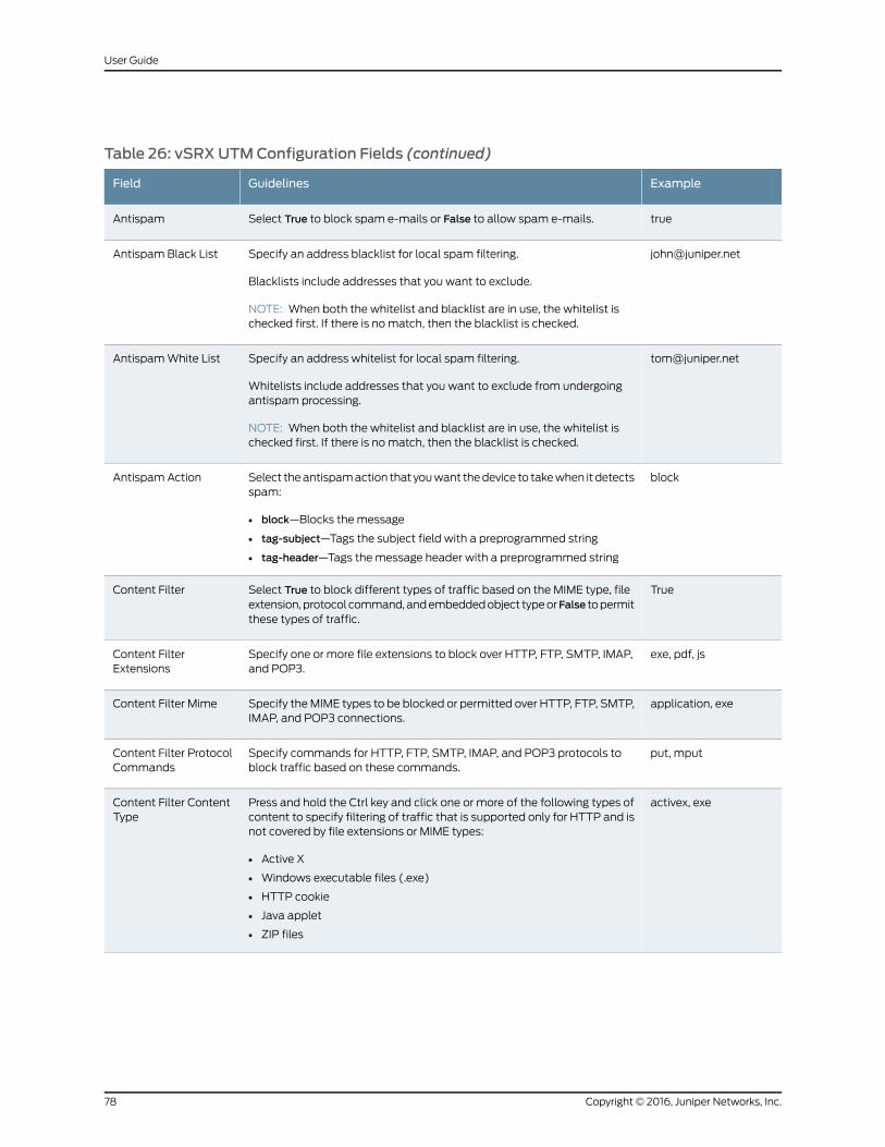
Table 26: vSRXUTMConfiguration Fields (continued)
ExampleGuidelinesField
trueSelect True to block spam e-mails or False to allow spam e-mails.Antispam
[email protected] an address blacklist for local spam filtering.
Blacklists include addresses that you want to exclude.
NOTE: When both the whitelist and blacklist are in use, the whitelist ischecked first. If there is nomatch, then the blacklist is checked.
Antispam Black List
[email protected] an address whitelist for local spam filtering.
Whitelists include addresses that you want to exclude from undergoingantispam processing.
NOTE: When both the whitelist and blacklist are in use, the whitelist ischecked first. If there is nomatch, then the blacklist is checked.
AntispamWhite List
blockSelect theantispamaction that youwant thedevice to takewhen it detectsspam:
• block—Blocks the message
• tag-subject—Tags the subject field with a preprogrammed string
• tag-header—Tags themessage header with a preprogrammed string
Antispam Action
TrueSelect True to block different types of traffic based on the MIME type, fileextension,protocol command,andembeddedobject typeorFalse topermitthese types of traffic.
Content Filter
exe, pdf, jsSpecify one or more file extensions to block over HTTP, FTP, SMTP, IMAP,and POP3.
Content FilterExtensions
application, exeSpecify theMIME types to be blocked or permitted over HTTP, FTP, SMTP,IMAP, and POP3 connections.
Content Filter Mime
put, mputSpecify commands for HTTP, FTP, SMTP, IMAP, and POP3 protocols toblock traffic based on these commands.
Content Filter ProtocolCommands
activex, exePress and hold the Ctrl key and click one or more of the following types ofcontent to specify filtering of traffic that is supported only for HTTP and isnot covered by file extensions or MIME types:
• Active X
• Windows executable files (.exe)
• HTTP cookie
• Java applet
• ZIP files
Content Filter ContentType
Copyright © 2016, Juniper Networks, Inc.78
User Guide
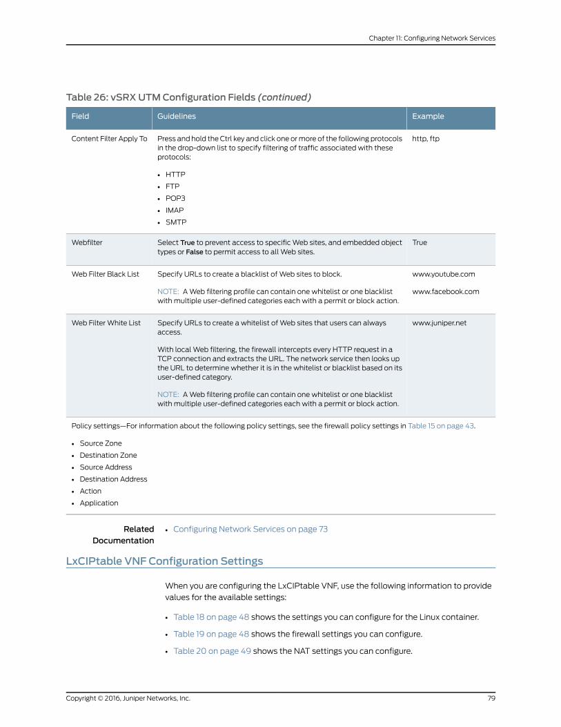
Table 26: vSRXUTMConfiguration Fields (continued)
ExampleGuidelinesField
http, ftpPress and hold theCtrl key and click one ormore of the following protocolsin the drop-down list to specify filtering of traffic associated with theseprotocols:
• HTTP
• FTP
• POP3
• IMAP
• SMTP
Content Filter Apply To
TrueSelect True to prevent access to specificWeb sites, and embedded objecttypes or False to permit access to all Web sites.
Webfilter
www.youtube.com
www.facebook.com
Specify URLs to create a blacklist of Web sites to block.
NOTE: AWeb filtering profile can contain one whitelist or one blacklistwith multiple user-defined categories each with a permit or block action.
Web Filter Black List
www.juniper.netSpecify URLs to create a whitelist of Web sites that users can alwaysaccess.
With local Web filtering, the firewall intercepts every HTTP request in aTCP connection and extracts the URL. The network service then looks upthe URL to determine whether it is in the whitelist or blacklist based on itsuser-defined category.
NOTE: AWeb filtering profile can contain one whitelist or one blacklistwith multiple user-defined categories each with a permit or block action.
Web Filter White List
Policy settings—For information about the following policy settings, see the firewall policy settings in Table 15 on page 43.
• Source Zone
• Destination Zone
• Source Address
• Destination Address
• Action
• Application
RelatedDocumentation
Configuring Network Services on page 73•
LxCIPtable VNF Configuration Settings
When you are configuring the LxCIPtable VNF, use the following information to provide
values for the available settings:
• Table 18 on page 48 shows the settings you can configure for the Linux container.
• Table 19 on page 48 shows the firewall settings you can configure.
• Table 20 on page 49 shows the NAT settings you can configure.
79Copyright © 2016, Juniper Networks, Inc.
Chapter 11: Configuring Network Services
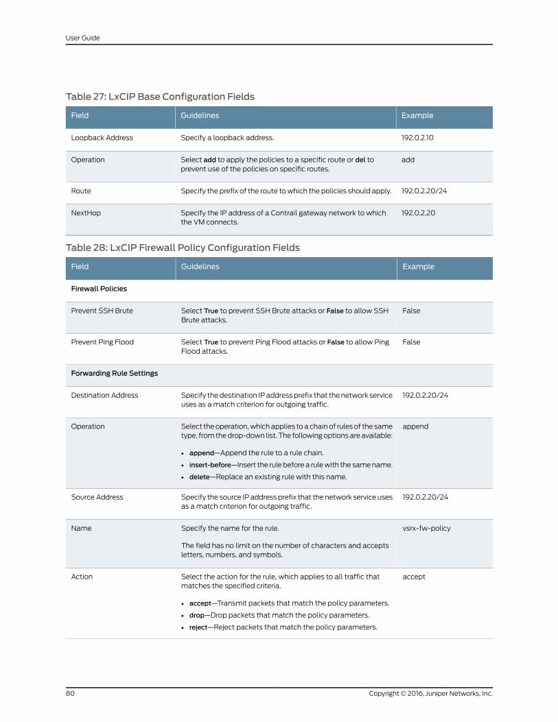
Table 27: LxCIP Base Configuration Fields
ExampleGuidelinesField
192.0.2.10Specify a loopback address.Loopback Address
addSelect add to apply the policies to a specific route or del toprevent use of the policies on specific routes.
Operation
192.0.2.20/24Specify the prefix of the route towhich the policies should apply.Route
192.0.2.20Specify the IP address of a Contrail gateway network to whichthe VM connects.
NextHop
Table 28: LxCIP Firewall Policy Configuration Fields
ExampleGuidelinesField
Firewall Policies
FalseSelect True to prevent SSH Brute attacks or False to allow SSHBrute attacks.
Prevent SSH Brute
FalseSelect True to prevent Ping Flood attacks or False to allow PingFlood attacks.
Prevent Ping Flood
Forwarding Rule Settings
192.0.2.20/24Specify thedestination IPaddressprefix that thenetwork serviceuses as amatch criterion for outgoing traffic.
Destination Address
appendSelect theoperation,whichapplies toachainof rulesof the sametype, fromthedrop-down list. The followingoptionsareavailable:
• append—Append the rule to a rule chain.
• insert-before—Insert the rulebeforea rulewith the samename.
• delete—Replace an existing rule with this name.
Operation
192.0.2.20/24Specify the source IPaddressprefix that thenetwork serviceusesas amatch criterion for outgoing traffic.
Source Address
vsrx-fw-policySpecify the name for the rule.
The field has no limit on the number of characters and acceptsletters, numbers, and symbols.
Name
acceptSelect the action for the rule, which applies to all traffic thatmatches the specified criteria.
• accept—Transmit packets that match the policy parameters.
• drop—Drop packets that match the policy parameters.
• reject—Reject packets that match the policy parameters.
Action
Copyright © 2016, Juniper Networks, Inc.80
User Guide
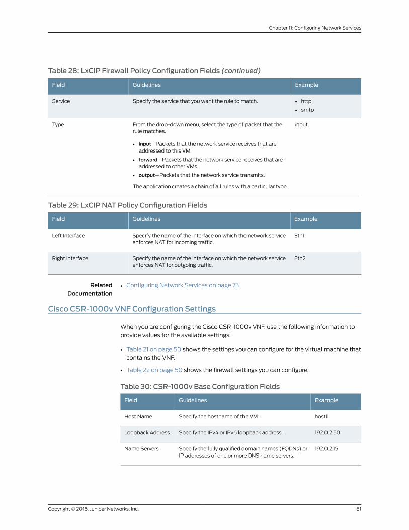
Table 28: LxCIP Firewall Policy Configuration Fields (continued)
ExampleGuidelinesField
• http
• smtp
Specify the service that you want the rule to match.Service
inputFrom the drop-downmenu, select the type of packet that therule matches.
• input—Packets that the network service receives that areaddressed to this VM.
• forward—Packets that the network service receives that areaddressed to other VMs.
• output—Packets that the network service transmits.
The application creates a chain of all ruleswith a particular type.
Type
Table 29: LxCIP NAT Policy Configuration Fields
ExampleGuidelinesField
Eth1Specify the name of the interface on which the network serviceenforces NAT for incoming traffic.
Left Interface
Eth2Specify the name of the interface on which the network serviceenforces NAT for outgoing traffic.
Right Interface
RelatedDocumentation
Configuring Network Services on page 73•
Cisco CSR-1000v VNF Configuration Settings
When you are configuring the Cisco CSR-1000v VNF, use the following information to
provide values for the available settings:
• Table 21 on page 50 shows the settings you can configure for the virtual machine that
contains the VNF.
• Table 22 on page 50 shows the firewall settings you can configure.
Table 30: CSR-1000v Base Configuration Fields
ExampleGuidelinesField
host1Specify the hostname of the VM.Host Name
192.0.2.50Specify the IPv4 or IPv6 loopback address.Loopback Address
192.0.2.15Specify the fully qualified domain names (FQDNs) orIP addresses of one or more DNS name servers.
Name Servers
81Copyright © 2016, Juniper Networks, Inc.
Chapter 11: Configuring Network Services
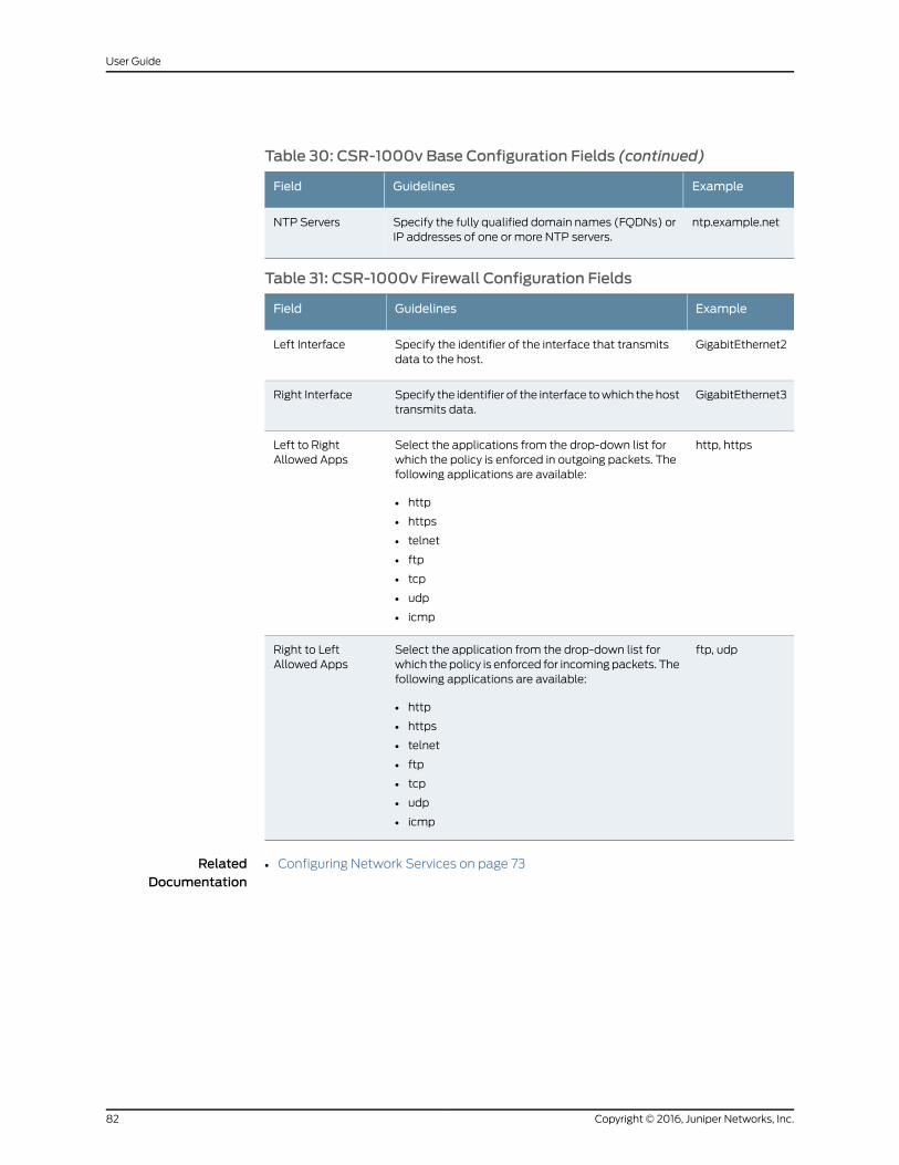
Table 30: CSR-1000v Base Configuration Fields (continued)
ExampleGuidelinesField
ntp.example.netSpecify the fully qualified domain names (FQDNs) orIP addresses of one or more NTP servers.
NTP Servers
Table 31: CSR-1000v Firewall Configuration Fields
ExampleGuidelinesField
GigabitEthernet2Specify the identifier of the interface that transmitsdata to the host.
Left Interface
GigabitEthernet3Specify the identifier of the interface towhich thehosttransmits data.
Right Interface
http, httpsSelect the applications from the drop-down list forwhich the policy is enforced in outgoing packets. Thefollowing applications are available:
• http
• https
• telnet
• ftp
• tcp
• udp
• icmp
Left to RightAllowed Apps
ftp, udpSelect the application from the drop-down list forwhich the policy is enforced for incoming packets. Thefollowing applications are available:
• http
• https
• telnet
• ftp
• tcp
• udp
• icmp
Right to LeftAllowed Apps
RelatedDocumentation
• Configuring Network Services on page 73
Copyright © 2016, Juniper Networks, Inc.82
User Guide
CHAPTER 12
Managing Requests and Designs
• Managing Requests for Network Services on page 83
• Managing Service Chain Designs on page 84
Managing Requests for Network Services
You use the Requests page to create andmanage requests for new network services.
When you start to design a network service for a request, the request is savedas adesign,
which you track on the Designs page. The request no longer appears on the Requests
page.
A request contains information about the required service, such as:
• The customer’s name.
• The requested functions in the network service, such as NAT.
• Attached notes about the performance goals for the service.
To view requests, click HOME in the toolbar and Requests in the left navigation bar.
• To start a design for a request:
1. Hover over the request.
A menu appears in the bottom right of the request.
2. Click BEGIN.
If the help overlay is visible, click Close Help.
You can also select I knowmyway around. Don’t show this again., and click Close
Help.
The BUILD page appears.
• To edit a request:
1. Hover over the request.
A menu appears in the bottom right of the request.
2. Click EDIT.
83Copyright © 2016, Juniper Networks, Inc.
A page in which you specify information about the request appears.
• To delete a request for a network service:
1. Hover over the request.
A menu appears in the bottom right of the request.
2. Click DELETE.
A page requesting confirmation for the deletion appears.
3. Click Yes to confirm that you want to delete the request.
The request is deleted.
• To view complete details for a request:
1. Click ShowDetails (hierarchy icon at the top left of the page).
2. Click the request in the hierarchy.
You see complete details for the request on one page. You can add additional notes to
this entry, and navigate to other designs in the hierarchy.
RelatedDocumentation
Viewing Information About VNFs on page 70•
• Performance Overview on page 71
Managing Service Chain Designs
You use the Designs Page to manage service chain designs that you have saved or
published.
To view a list of designs that you have saved or published, click HOME in the toolbar and
Designs in the left navigation bar.
• Tomodify a design that you have saved or published, click Edit from themenu at the
end of the appropriate row.
The BUILD page appears, displaying information for the service chain.
• To post a completed design to the Network Service catalog:
1. Select Publish from themenu at the end of the appropriate row.
The Publish NSD page appears.
2. Specify an official name (that customers see) for this network service.
The field accepts up to 60 characters, including letters, numbers, and symbols.
3. Specify a description of the service for customers to read.
The field accepts up to 500 characters, including letters, numbers, and symbols.
Copyright © 2016, Juniper Networks, Inc.84
User Guide
4. Select the type of service from themenu.
5. Click Publish.
A message indicating failure or success appears briefly in the bottom right of the
page.
• To delete a design that you have saved or published:
1. Click Delete from themenu at the end of the appropriate row.
A page requesting confirmation for the deletion appears.
2. Click Yes to confirm that you want to delete the design.
The design is deleted and is then displayed on the Requests Page.
• To delete multiple designs that you have saved or published:
1. From the list of Designs, select those that you want to delete.
2. Click Delete NSD at the top right of the page.
A page requesting confirmation for the deletion appears.
3. Click Yes to confirm that you want to delete the designs.
The designs are deleted and are then displayed on the Requests Page.
• To copy one or more designs that you have saved or published:
1. From the list of designs, select those that you want to you want to copy.
2. Click Copy NSD at the top right of the page.
A page requesting confirmation for the copying appears.
3. Click Yes to confirm that you want to copy the designs.
The additional services appear in the table with the status Validated.
• To view complete details for a design:
1. Click ShowDetails (hierarchy icon at the top left of the page).
2. Click the design in the hierarchy.
You see complete details for the design on one page.
RelatedDocumentation
• Network Services and Service Chains Overview on page 62
• Designing Service Chains for Network Services on page 67
85Copyright © 2016, Juniper Networks, Inc.
Chapter 12: Managing Requests and Designs

Copyright © 2016, Juniper Networks, Inc.86
User Guide
PART 5
Service and Infrastructure Monitor
• Service and Infrastructure Monitor introduction on page 89
• Monitoring Activities in the Deployment on page 91
87Copyright © 2016, Juniper Networks, Inc.

Copyright © 2016, Juniper Networks, Inc.88
User Guide
CHAPTER 13
Service and Infrastructure Monitorintroduction
• Service and Infrastructure Monitor Overview on page 89
• Accessing the Service and Infrastructure Monitor GUI on page 90
Service and Infrastructure Monitor Overview
Service and Infrastructure Monitor operates with the third-party monitoring software
Icinga to provide completemonitoring and troubleshooting of the CloudCPECentralized
Deployment Model.
When you deploy the Cloud CPE Centralized Deployment Model, an Icinga agent is
installed on servers and virtual machines (VMs), which enables Icinga to monitor data
on:
• Physical servers
• VMs that host virtualized network functions (VNFs)
• VMs that host microservices
Service and Infrastructure Monitor collects events frommicroservices in the Cloud CPE
Centralized Deployment Model, and correlates the events to provide information about
network service, their component VNFs, and the VMs that host the VNFs.
All data is presented through the IcingaGUI. You use theGUI to obtain both a quick visual
display of the Cloud CPE Centralized Deployment Model status andmore detailed lists
of event messages.
Colored squares, which may contain numbers, in the GUI provide a visual status of the
Cloud CPE Centralized Deployment Model network.
• A green square indicates the number of items that are working correctly.
• A yellow square indicates the number of items with potential problems to investigate.
• A red square indicates the number of items that are not working.
• A purple square indicates the number of items with a failed connection.
89Copyright © 2016, Juniper Networks, Inc.
The following options in the left navigation pane of the Icinga GUI are customized for the
Cloud CPE Centralized Deployment Model:
• Dashboard
• Network Services
• Infrastructure
Other features in the Icinga GUI are not customized and appear in the standard Icinga
GUI.
Use this Service and Infrastructure Monitor documentation for information about using
the customized options in the GUI. See the Icinga documentation for a general overview
of the GUI and information about all non-customized features.
RelatedDocumentation
Monitoring Network Services on page 91•
• MonitoringVNFsUsed inNetworkServicesand theVMsThatHost theVNFsonpage92
• Monitoring Microservices on page 93
• Monitoring Microservices and Their Host VMs on page 95
• Monitoring Physical Servers on page 96
Accessing the Service and Infrastructure Monitor GUI
To access the GUI for Service and Infrastructure Monitor:
1. Using a web browser, access the URL for Service and Infrastructure Monitor.
For example, if the IP address is 192.0.2.9, the URL is http://192.0.2.9/icingaweb2.
2. Log in with the username icinga and the password csoJuniper.
RelatedDocumentation
• Service and Infrastructure Monitor Overview on page 89
Copyright © 2016, Juniper Networks, Inc.90
User Guide
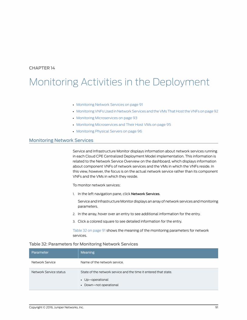
CHAPTER 14
Monitoring Activities in the Deployment
• Monitoring Network Services on page 91
• MonitoringVNFsUsed inNetworkServicesand theVMsThatHost theVNFsonpage92
• Monitoring Microservices on page 93
• Monitoring Microservices and Their Host VMs on page 95
• Monitoring Physical Servers on page 96
Monitoring Network Services
Service and Infrastructure Monitor displays information about network services running
in each Cloud CPE Centralized Deployment Model implementation. This information is
related to the Network Service Overview on the dashboard, which displays information
about component VNFs of network services and the VMs in which the VNFs reside. In
this view, however, the focus is on the actual network service rather than its component
VNFs and the VMs in which they reside.
Tomonitor network services:
1. In the left navigation pane, click Network Services.
Serviceand InfrastructureMonitordisplaysanarrayofnetwork servicesandmonitoring
parameters.
2. In the array, hover over an entry to see additional information for the entry.
3. Click a colored square to see detailed information for the entry.
Table 32 on page 91 shows themeaning of the monitoring parameters for network
services.
Table 32: Parameters for Monitoring Network Services
MeaningParameter
Name of the network service.Network Service
State of the network service and the time it entered that state.
• Up—operational
• Down—not operational
Network Service status
91Copyright © 2016, Juniper Networks, Inc.
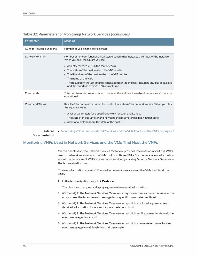
Table 32: Parameters for Monitoring Network Services (continued)
MeaningParameter
Number of VNFs in the service chain.Num of Network Functions
Number of network functions in a colored square that indicates the status of the instance.When you click the square you see:
• An entry for each VNF in the service chain.
• The status of the host in which the VNF resides.
• The IP address of the host in which the VNF resides.
• The name of the VNF.
• The result from the last ping the Icinga agent sent to the host, including any loss of packets,and the round trip average (RTA) travel time.
Network Function
Total numberof commands issued tomonitor thestatusof thenetwork service since it becameoperational.
Commands
Result of the commands issued to monitor the status of the network service. When you clickthe square you see:
• A list of parameters for a specific network function and its host.
• The state of the parameter and how long the parameter has been in that state.
• Additional details about the state of the host.
Command Status
RelatedDocumentation
MonitoringVNFsUsed inNetworkServicesand theVMsThatHost theVNFsonpage92•
Monitoring VNFs Used in Network Services and the VMs That Host the VNFs
On the dashboard, the Network Service Overview provides information about the VNFs
used innetwork servicesand theVMs thathost thoseVNFs.Youcanalsoview information
about the component VNFs in a network service by clicking Monitor Network Services in
the left navigation bar.
To view information about VNFs used in network services and the VMs that host the
VNFs:
1. In the left navigation bar, click Dashboard.
The dashboard appears, displaying several arrays of information.
2. (Optional) In the Network Services Overview array, hover over a colored square in the
array to see the latest event message for a specific parameter and host.
3. (Optional) In the Network Services Overview array, click a colored square to see
detailed information for a specific parameter and host.
4. (Optional) In the Network Services Overview array, click an IP address to view all the
event messages for a host.
5. (Optional) In the Network Services Overview array, click a parameter name to view
event messages on all hosts for that parameter.
Copyright © 2016, Juniper Networks, Inc.92
User Guide
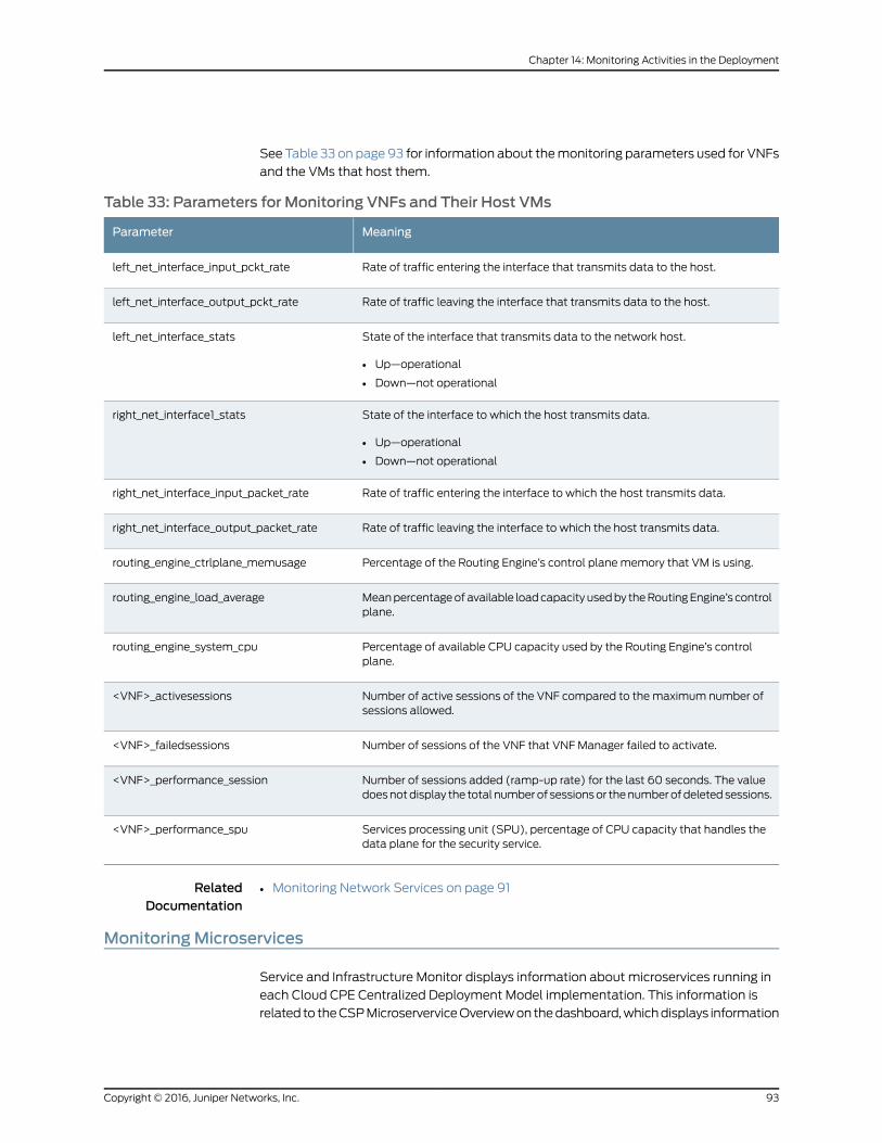
SeeTable 33 on page 93 for information about themonitoring parameters used for VNFs
and the VMs that host them.
Table 33: Parameters for Monitoring VNFs and Their Host VMs
MeaningParameter
Rate of traffic entering the interface that transmits data to the host.left_net_interface_input_pckt_rate
Rate of traffic leaving the interface that transmits data to the host.left_net_interface_output_pckt_rate
State of the interface that transmits data to the network host.
• Up—operational
• Down—not operational
left_net_interface_stats
State of the interface to which the host transmits data.
• Up—operational
• Down—not operational
right_net_interface1_stats
Rate of traffic entering the interface to which the host transmits data.right_net_interface_input_packet_rate
Rate of traffic leaving the interface to which the host transmits data.right_net_interface_output_packet_rate
Percentage of the Routing Engine’s control planememory that VM is using.routing_engine_ctrlplane_memusage
Meanpercentageofavailable loadcapacity usedby theRoutingEngine’s controlplane.
routing_engine_load_average
Percentage of available CPU capacity used by the Routing Engine’s controlplane.
routing_engine_system_cpu
Number of active sessions of the VNF compared to the maximum number ofsessions allowed.
<VNF>_activesessions
Number of sessions of the VNF that VNF Manager failed to activate.<VNF>_failedsessions
Number of sessions added (ramp-up rate) for the last 60 seconds. The valuedoesnotdisplay the total numberof sessionsor thenumberofdeletedsessions.
<VNF>_performance_session
Services processing unit (SPU), percentage of CPU capacity that handles thedata plane for the security service.
<VNF>_performance_spu
RelatedDocumentation
Monitoring Network Services on page 91•
MonitoringMicroservices
Service and Infrastructure Monitor displays information about microservices running in
each Cloud CPE Centralized Deployment Model implementation. This information is
related to theCSPMicroserverviceOverviewon thedashboard,whichdisplays information
93Copyright © 2016, Juniper Networks, Inc.
Chapter 14: Monitoring Activities in the Deployment
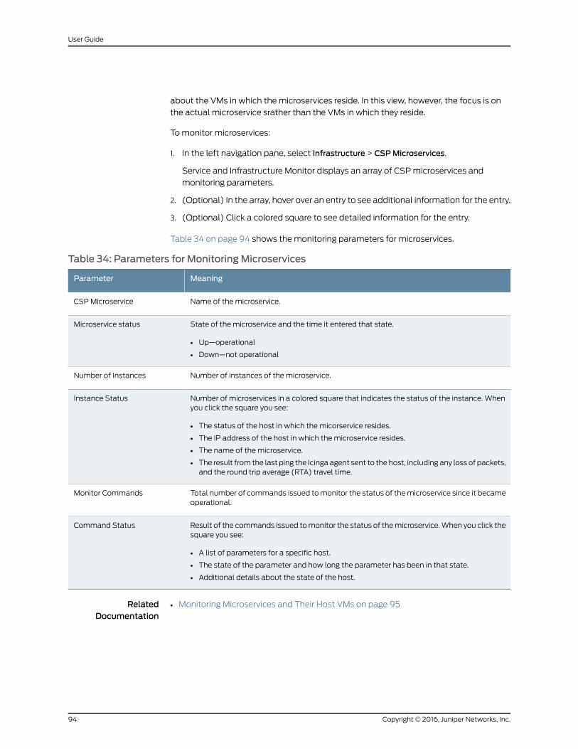
about the VMs in which the microservices reside. In this view, however, the focus is on
the actual microservice srather than the VMs in which they reside.
Tomonitor microservices:
1. In the left navigation pane, select Infrastructure > CSPMicroservices.
Service and Infrastructure Monitor displays an array of CSPmicroservices and
monitoring parameters.
2. (Optional) In the array, hover over an entry to see additional information for the entry.
3. (Optional) Click a colored square to see detailed information for the entry.
Table 34 on page 94 shows themonitoring parameters for microservices.
Table 34: Parameters for MonitoringMicroservices
MeaningParameter
Name of the microservice.CSPMicroservice
State of the microservice and the time it entered that state.
• Up—operational
• Down—not operational
Microservice status
Number of instances of the microservice.Number of Instances
Number of microservices in a colored square that indicates the status of the instance. Whenyou click the square you see:
• The status of the host in which the micorservice resides.
• The IP address of the host in which the microservice resides.
• The name of the microservice.
• The result from the last ping the Icinga agent sent to the host, including any loss of packets,and the round trip average (RTA) travel time.
Instance Status
Total number of commands issued tomonitor the status of themicroservice since it becameoperational.
Monitor Commands
Result of the commands issued tomonitor the status of themicroservice.When you click thesquare you see:
• A list of parameters for a specific host.
• The state of the parameter and how long the parameter has been in that state.
• Additional details about the state of the host.
Command Status
RelatedDocumentation
Monitoring Microservices and Their Host VMs on page 95•
Copyright © 2016, Juniper Networks, Inc.94
User Guide
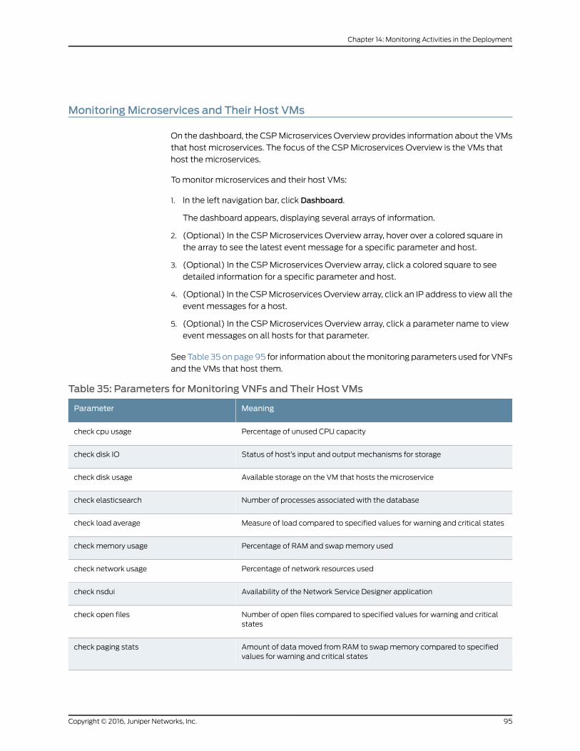
MonitoringMicroservices and Their Host VMs
On the dashboard, the CSPMicroservices Overview provides information about the VMs
that host microservices. The focus of the CSPMicroservices Overview is the VMs that
host the microservices.
Tomonitor microservices and their host VMs:
1. In the left navigation bar, click Dashboard.
The dashboard appears, displaying several arrays of information.
2. (Optional) In the CSPMicroservices Overview array, hover over a colored square in
the array to see the latest event message for a specific parameter and host.
3. (Optional) In the CSPMicroservices Overview array, click a colored square to see
detailed information for a specific parameter and host.
4. (Optional) In the CSPMicroservices Overview array, click an IP address to view all the
event messages for a host.
5. (Optional) In the CSPMicroservices Overview array, click a parameter name to view
event messages on all hosts for that parameter.
See Table 35 on page95 for information about themonitoring parameters used for VNFs
and the VMs that host them.
Table 35: Parameters for Monitoring VNFs and Their Host VMs
MeaningParameter
Percentage of unused CPU capacitycheck cpu usage
Status of host’s input and output mechanisms for storagecheck disk IO
Available storage on the VM that hosts the microservicecheck disk usage
Number of processes associated with the databasecheck elasticsearch
Measure of load compared to specified values for warning and critical statescheck load average
Percentage of RAM and swapmemory usedcheck memory usage
Percentage of network resources usedcheck network usage
Availability of the Network Service Designer applicationcheck nsdui
Number of open files compared to specified values for warning and criticalstates
check open files
Amount of data moved from RAM to swapmemory compared to specifiedvalues for warning and critical states
check paging stats
95Copyright © 2016, Juniper Networks, Inc.
Chapter 14: Monitoring Activities in the Deployment
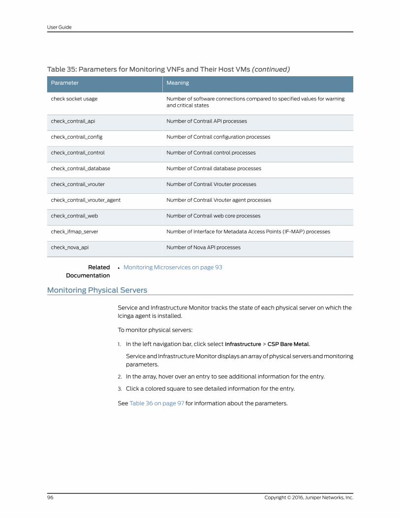
Table 35: Parameters for Monitoring VNFs and Their Host VMs (continued)
MeaningParameter
Number of software connections compared to specified values for warningand critical states
check socket usage
Number of Contrail API processescheck_contrail_api
Number of Contrail configuration processescheck_contrail_config
Number of Contrail control processescheck_contrail_control
Number of Contrail database processescheck_contrail_database
Number of Contrail Vrouter processescheck_contrail_vrouter
Number of Contrail Vrouter agent processescheck_contrail_vrouter_agent
Number of Contrail web core processescheck_contrail_web
Number of Interface for Metadata Access Points (IF-MAP) processescheck_ifmap_server
Number of Nova API processescheck_nova_api
RelatedDocumentation
Monitoring Microservices on page 93•
Monitoring Physical Servers
Service and Infrastructure Monitor tracks the state of each physical server on which the
Icinga agent is installed.
Tomonitor physical servers:
1. In the left navigation bar, click select Infrastructure > CSP BareMetal.
Serviceand InfrastructureMonitordisplaysanarrayofphysical serversandmonitoring
parameters.
2. In the array, hover over an entry to see additional information for the entry.
3. Click a colored square to see detailed information for the entry.
See Table 36 on page 97 for information about the parameters.
Copyright © 2016, Juniper Networks, Inc.96
User Guide
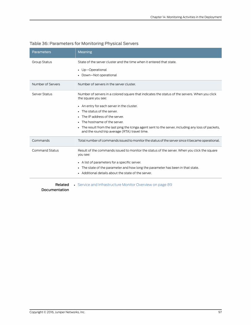
Table 36: Parameters for Monitoring Physical Servers
MeaningParameters
State of the server cluster and the time when it entered that state.
• Up—Operational
• Down—Not operational
Group Status
Number of servers in the server cluster.Number of Servers
Number of servers in a colored square that indicates the status of the servers. When you clickthe square you see:
• An entry for each server in the cluster.
• The status of the server.
• The IP address of the server.
• The hostname of the server.
• The result from the last ping the Icinga agent sent to the server, including any loss of packets,and the round trip average (RTA) travel time.
Server Status
Total numberof commands issued tomonitor thestatusof theserver since it becameoperational.Commands
Result of the commands issued to monitor the status of the server. When you click the squareyou see:
• A list of parameters for a specific server.
• The state of the parameter and how long the parameter has been in that state.
• Additional details about the state of the server.
Command Status
RelatedDocumentation
• Service and Infrastructure Monitor Overview on page 89
97Copyright © 2016, Juniper Networks, Inc.
Chapter 14: Monitoring Activities in the Deployment

Copyright © 2016, Juniper Networks, Inc.98
User Guide