Embed Size (px)
Citation preview

CONTRACT DOCUMENTS ANDTECHNICAL SPECIFICATIONS
FOR
Seale Ground Storage Tank No. 1 Painting and Rehabilitation Project
SAWS Job No. 11-0107Solicitation No. B-12-052-MF
August 2012
Prepared by:
TETRA TECH, INC.
Texas Registered Engineering Firm No. 3924
700 North Saint Mary’s Street, Suite 300San Antonio, Texas 78205
Phone 210.226.2922 / Fax 210.226.8497


SEALE GST NO. 1 PAINTING TABLE OF CONTENTS& REHABILITATION PROJECT AUGUST 2012
TOC-1
SAN ANTONIO WATER SYSTEMSEALE GROUND STORAGE TANK NO. 1
PAINTING AND REHABILITATION PROJECT
TABLE OF CONTENTS
PART I: CONTRACT DOCUMENTSPAGE
Invitation for Competitive Sealed Proposals ......................................................... IV 1
Instructions to Respondents .................................................................................. IR 1-7
Supplementary Instructions to Respondents .......................................................... SIR 1-7
Workers’ Compensation Insurance Coverage Requirements ................................. WC 1-3
Submittal Checklist ...... ....................................................................................... SCL 1
Price Proposal .............. ....................................................................................... P 1-5
Good Faith Effort Plan . ....................................................................................... GFEP 1-5
SAWS Subcontractor Payment Compliance.......................................................... B2G
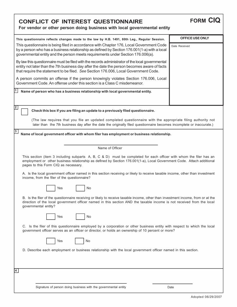
Conflict of Interest Questionnaire ......................................................................... CIQ 1-2
General Conditions of the Contract ....................................................................... GC 1-37
Contract Agreement .... ....................................................................................... CA 1-2
Performance Bond........ ....................................................................................... PB 1
Payment Bond .............. ....................................................................................... PB 2
Workers’ Compensation Exhibit “A”.................................................................... WA 1-3
Contractor Suspension Policy Exhibit “B” ............................................................ SP 1-9
Contractor Security Procedures Exhibit “C” ......................................................... 1 of 1
W-9 Request for Taxpayer Identification Number and Certification ...................... W-9
Instructions for Completing the ACORD Certificate of Liability Insurance ........... 20 pgs
Supplementary Conditions ................................................................................... SUC 1-3
Special Conditions ....... ....................................................................................... SPC 1
(Separate Documents)
COSA Standard Specifications for Public Works Construction (current revision)
SAWS Specifications for Water and Sanitary Sewer Construction (current revision)

SEALE GST NO. 1 PAINTING TABLE OF CONTENTS& REHABILITATION PROJECT AUGUST 2012
TOC-2
PART II: TECHNICAL SPECIFICATIONS
PAGEDIVISION 1 - GENERAL REQUIREMENTS
01010 Summary of Work 1-5
01015 Use of Premises 1-4
01025 Measurement and Payment 1-10
01040 Coordination 1-7
01045 Cutting and Patching 1-2
01050 Field Engineering 1-2
01060 Regulatory Requirements 1-9
01065 Contractor Safety Plan 1-4
01092 Abbreviations 1-5
01200 Project Meetings 1-2
01300 Submittals 1-7
01310 Progress Schedules 1-5
01380 Construction Photographs 1
01381 Pre-Construction Video s 1-2
01400 Quality Control 1-3
01410 Testing Laboratory Services 1-15
01430 Operation and Maintenance Data 1-7
Maintenance Summary Form 1-2
01500 Construction Facilities and Temporary Controls 1-7
01561 Trench Safety System 1-3
01566 Waste and Salvageable Material 1-2
01568 Erosion and Sedimentation Controls 1-4
01600 Material and Equipment 1-4
01640 Manufacturer's Field Services 1-4
01650 Starting of Systems 1-3
01651 Facility Startup 1-5
01700 Contract Closeout 1-2
01720 Project Record Documents 1-2

SEALE GST NO. 1 PAINTING TABLE OF CONTENTS& REHABILITATION PROJECT AUGUST 2012
TOC-3
PAGEDIVISION 2 – SITE WORK
02060 Demolition 1-7
02100 Site Preparation 1-4
02205 Excavation 1-3
02208 Lime Treated Subgrade 1-5
02210 Subgrade Preparation 1-2
02212 Removing Existing Pavements and Structures 1-3
02215 Fill and Backfill 1-6
02220 Excavating, Backfilling, and Compaction for Utilities 1-14
02480 Landscaping 1-10
02481 Tree and Landscape Protection 1-4
02500 Flexible Base 1-5
02502 Prime Coat 1-3
02503 Tack Coat 1-2
02513 Asphaltic Concrete Paving 1-17
02821 Chain-Link Fences and Gates 1-13
DIVISION 3 - CONCRETE
03100 Concrete Formwork 1-6
03200 Concrete Reinforcement 1-5
03300 Cast-in-Place Concrete (Canopy Cover) 1-18
03301 Cast-in-Place Concrete 1-10
03600 Grout 1-6
Supplemental Forms 1-4
DIVISION 5 - METALS
05120 Structural Steel 1-10
05200 Steel Joists 1-6
05310 Steel Roof Deck 1-5
05500 Metal Fabrications 1-4

SEALE GST NO. 1 PAINTING TABLE OF CONTENTS& REHABILITATION PROJECT AUGUST 2012
TOC-4
PAGEDIVISION 7 – THERMAL AND MOISTURE PROTECTION
07610 Metal Roofing 1-6
DIVISION 8 – DOORS AND HARDWARE
08310 Access Hatches 1-5
DIVISION 9 - FINISHES
09800 General Specifications for Coating System 1-14
09871 Exterior Coating System for Steel Storage Tank 1-3
09872 Interior Coating System for Steel Storage Tank 1-4
09885 General Coating System for Yard Pumps, Piping
and Electrical Systems 1-3
09986 Coating System for Concrete Surfaces 1-2
09940 Removal of Lead Based Coatings 1-13
DIVISION 13 - SPECIAL CONSTRUCTION
13110 Cathodic Protection System 1-5
13200 Steel Water Storage Tank Rehabilitation 1-7
13220 Disinfection of Water Distribution Systems 1-2
DIVISION 15 - MECHANICAL
15072 Potable Water Piping 1-10
15073 Disinfection of Waterlines 1-4
15074 Water Pipeline Testing 1-7
15099 Pipe Corrosion Control 1-4
15100 Valves and Actuators 1-13
15190 Mechanical Identification 1-2

SEALE GST NO. 1 PAINTING TABLE OF CONTENTS& REHABILITATION PROJECT AUGUST 2012
TOC-5
PAGEDIVISION 16 - ELECTRICAL
16010 Basic Electrical Requirements 1-5
16050 Basic Electrical Materials and Methods 1-11
16110 Raceways 1-11
16120 Conductors 1-8
16411 Power System Study 1-4
16451 Ground Grid, Grounding and Lightning Protection 1-5
16930 Instrumentation 1-6
16940 Instrumentation Heat Trace System 1-2
16950 Electrical Testing 1-6
APPENDIX A: Site Soil and Paint Chip Samples
PART III: CONTRACT DRAWINGS (Construction Plans)

This page intentionally left blank.

INVITATION FOR COMPETITIVE SEALED PROPOSALS
Solicitation No. B-12-052-MF
Sealed proposals are requested by the San Antonio Water System for the Seale Ground Storage Tank No. 1 Painting and Rehabilitation Project, SAWS Job No. 11-0107. The project includes, but is not limited to, the following: Rehabilitation of a 3,000,000 gallon welded steel, ground storage tank, including the surface preparation and repainting of the interior and exterior surfaces; replacement of specified tank appurtenances; surface preparation and painting of three well pump and piping assemblies; surface preparation and painting of five (5) high service pump assemblies; replacement of five flow meters and two check valves; replacement of two concrete vaults and one new concrete vault; site paving and sidewalk improvements; site fencing improvements; a new shade canopy; electrical equipment improvements; and other miscellaneous work. To view additional project information, as well as obtain the plans and specifications for this project, visit our website located at www.saws.org and click on the Business Center. Then select Bidder, Consultant, and Vendor Registration, which is located on the left-hand side of the screen. Select the Register Now button and proceed with registration. For difficulties downloading plans and specifications, contact the Contracting Department at 210-233-3341. For questions regarding this solicitation, technical questions or additional information, please contact Maria Franco, Contractor Administrator, in writing via email to: [email protected] by fax to (210) 233-4622 until 4:00 PM (CST) on September 7, 2012. Answers to the questions will be posted to the web site by 4:00 PM (CST) on September 11, 2011 as a separate document or included as part of an addendum. A Mandatory Pre-Proposal Meeting will be held at September 5, 2012 at 10:00 a.m. at the San Antonio Water System’s Customer Service Building, 4th floor, Conference Room 452, 2800 U.S. Hwy 281 North, San Antonio, Texas. Please be advised that under no circumstances shall any late or non-attendee(s) to the Mandatory Pre-Proposal Meeting be allowed to submit a competitive sealed proposal for the project. Immediately following the pre-proposal meeting there will be a MANDATORY site visit. Sealed proposals will be received by the Contract Administration Division, 2800 U.S. Hwy 281 North, Customer Center Building, Suite 171, San Antonio, Texas 78212, until September 14, 2012 at 2:00 p.m. Proposals will then be publicly opened and read aloud in Contract Administration, Suite 169, Customer Center Building, 2800 U.S. Hwy 281 North, San Antonio, Texas. This solicitation requires a Qualification Package, Good Faith Effort Plan, and Conflict of Interest Questionnaire, which should be included as part of the proposals and will become part of the construction documents. Each proposal must be accompanied by a cashier's check, certified check, or bid bond in an amount not less than five percent of the total price proposal.
IV-1

IR-1
INSTRUCTIONS TO RESPONDENTS
1. Proposals will be submitted in accordance with the following:
a. Eight (8) sealed proposals, one (1) Original, clearly marked and signed in blue ink, and seven(7) copies will be received by the office of Contract Administration Division, San AntonioWater System, 2800 U.S. Hwy 281 North, Customer Center Building, Suite 171, SanAntonio, Texas 78212, until the time specified in the Invitation for Competitive SealedProposals.
b. If the submittal of a sealed proposal is by any means other than personal/hand delivery, then itis the Respondents sole responsibility to ensure the proposal is delivered to the exact locationspecified above, no later than the exact time specified in the Invitation for Competitive SealedProposals.
c. All sealed proposals errantly submitted or delivered to a location other than the exact locationstated above will be returned unopened.
d. All sealed proposals received after the exact time set for in the Invitation for CompetitiveSealed Proposals will be returned unopened.
e. The San Antonio Water System Contracting Office may, at its sole discretion, without waiverof rights or authority, in equity or at law, return unopened, any sealed proposals not meetingthe exact requirements as stated above.
2. Proposals will be opened, evaluated and awarded in accordance with the following:
a. Proposals will be opened in a public setting and the names of the offerors and all prices statedin each proposal will be read aloud by a Contract Administration representative.
b. No proposal may be withdrawn after the solicitation deadline without the written consent of aContract Administration representative.
c. Not later than the 45th day after the date of the opening of the proposals, SAWS will evaluatethe responses based on the selection criteria set out herein and on its ranking evaluation.
d. SAWS will select the offeror that offers the best value for SAWS. In determining best value,SAWS is not restricted to consider price alone, but will consider the other factors stated inthe selection criteria set out in the request for sealed proposals.
e. SAWS will first attempt to negotiate a contract with the selected offeror. SAWS and itsengineers or architects may discuss with the selected offeror options for a scope or timemodification and any price change associated with the modification. If SAWS is unable tonegotiate a contract with the selected offeror, SAWS shall, formerly and in writing, end

IR-2
negotiations with that offeror and proceed to the next offeror in the order of selection rankinguntil a contract is reached or all proposals are rejected.
3. All proposals must be accompanied by Certified or Cashier's Check or an approved Bid Bond in theamount of not less than five percent (5%) of the total offer, payable without recourse to the SanAntonio Water System. Surety shall provide a copy of the Power of Attorney authorizing theExecuting Agent the authority to execute the bid bond documents and bind the Surety to the bid bondconditions. Surety shall also provide evidence that the Surety is authorized to provide service in theState of Texas at the amount on the bid bond. Proposals without bond Security will not beconsidered.
4. Proposals must be submitted with the original price proposal form attached herein and shall be sealedin an envelope plainly marked on the outside with job number, the date and time of the solicitationdeadline, and the name of material or services offered on. Samples, when required, must be submittedwithin the time specified at no expense to the San Antonio Water System. If not destroyed or usedup during testing, samples will be returned upon request at the Respondent's expense.
5. Proposals will be prepared in accordance with the following:
(a) The Respondent shall thoroughly examine the drawings, specifications, schedule, instructions andall other documents.
(b) Respondent shall make all investigations necessary to inform himself thoroughly regarding plantand facilities for delivery of material and equipment as required by the project conditions.Respondent shall determine for himself by examination at the site of the Work the conditionswhich exist and under which he will be expected to perform his Work. Prior to presenting theirsealed proposals, Respondents are encouraged to take their own representative samples ofexisting coating systems; e.g., exterior, interior and piping coating systems, test samples in a statecertified laboratory for total lead, chromium and cadmium, and use their best judgment indetermining their construction method, demolition method, disposal of waste material, laborhazard protection, equipment and materials to perform the scope of work in full compliance withEPA, TCEQ, an OSHA Regulations. SAWS will presume that the necessary examination,samples, and testing have been conducted prior to Respondents submitting their offer forconsideration. No plea of ignorance by the Respondent of conditions that exist, or that mayhereafter exist as a result of failure or omission on the part of the Respondent to make thenecessary examinations and investigations to fulfill in every detail the requirements of the contractdocuments, will be accepted as the basis for varying the requirements of the San Antonio WaterSystem or the compensation to the Contractor.
(c) The Respondent is required to submit a Contractor’s Qualification Statement formatted asdirected in the Supplementary Instructions to Respondents.
(d) The Respondent shall furnish all information required by the Price Proposal form. TheRespondent shall print or type his name and manually sign the schedule and each continuationsheet on which any entry is made.

IR-3
(e) The Respondent is required to submit a Good Faith Effort Plan and SMWB CertificationCertificate as part of the proposal. Respondents and/or their agents may contact the SAWS SmallBusiness Liaison Office for assistance or clarification with issues specifically related to the Small,Minority, and Woman Business (SMWB) Program policy and/or completion of the Good FaithEffort Plan form. Point of contact SAWS’ SMWB Development Officer at 210-233-3420.
(f) The Respondent is required to submit a Conflict of Interest Questionnaire (CIQ Form). EffectiveJanuary 1, 2006, Chapter 176 of the Texas Local Government Code requires that persons, ortheir agents, who seek to contract for the sale or purchase of property, goods, or services withSAWS shall file a completed Conflict of Interest Questionnaire (CIQ) with SAWS. The CIQ willbe submitted as part of the proposal. Form is available from the Texas Ethics Commission atwww.ethics.state.tx.us. Please consult your own legal advisor if you have questions regarding thestatute or form.
(g) The Respondent is required to submit as part of the proposal a letter from the insurance providerstating provider’s commitment to insure the Contractor for the types of coverage’s as specified inthe General Conditions Section 5.7 – Contractor’s Insurance Requirements, if awarded thecontract.
(h) Pursuant to Section 151.311 of the Texas Tax Code, as amended, in order for the San AntonioWater System to continue to benefit from its status as a State Sales and Use Tax ExemptOrganization, construction contracts must be awarded on a "separated contract" basis. A"separated contract" is one that distinguishes the value of the tangible personal property(materials such as pipe, bricks, lumber, concrete, paint, etc.) to be incorporated into the projectfrom the total contract price. Under the "separated contract" format, the contractor in effectbecomes a "seller" to the San Antonio Water System of materials that are to be physicallyincorporated into the project realty. As a "seller", the contractor will issue a "Texas Certificate ofResale" to the supplier in lieu of paying the sales tax on materials at the time of purchase. Thecontractor will also issue a "Certificate of Exemption" to the supplier demonstrating that thepersonal property is being purchased for resale and that the resale is to a department of the City ofSan Antonio, Texas, which is a sales tax exempt entity. Contractors should be careful to consultthe most recent guidelines of the State Comptroller of Public Accounts regarding the sales taxstatus of supplies and equipment that are used and consumed during project work but that are notphysically incorporated into the project realty. Contractors that have questions about this law areasked to inquire with the State Comptroller of Public Accounts, Tax Administration Division,State of Texas, Austin, Texas 78774 (512) 463-4934. Respondents will not include any federaltaxes in offered prices since the San Antonio Water System is exempt from payment of suchtaxes. "Texas Certificates of Exemption", "Texas Certificates of Resale" and "Texas Sales TaxPermits" are forms available to the contractor through the regional offices of the StateComptroller of Public Accounts.
6. Any catalogue or manufacturer's reference used in describing an item is merely descriptive, and notrestrictive unless otherwise noted, and is used only to indicate type and quality of material. Whenitems proposed differ in any way from those specified, Respondents are required to state exactly what

IR-4
they intend to furnish. Otherwise, they shall be required to furnish the items as specified.
7. The work shall be done and completed in accordance with the following Contract Documents asfurnished by the San Antonio Water System:
a. The Invitation for Competitive Sealed Proposalsb. The Instructions to Respondentsc. The Supplementary Instructions to Respondentsd. The Price Proposale. The Payment Bondf. The Performance Bondg. The General Conditions of the Contracth. The Special Conditions of the Contracti. The Supplementary Conditions of the Contractj. The Construction Specificationsk. The Standard Drawingsl. Addendam. Change Ordersn. Good Faith Effort Plano. Conflict of Interest Questionnaire
8. The successful Respondent will be required to execute the standard San Antonio Water SystemContract Agreement, Performance and Payment Bonds as outlined in the General Conditions. Theseforms will be prepared and furnished by the San Antonio Water System. Surety shall provide a copyof the Power of Attorney authorizing the Executing Agent the authority to execute the bonddocuments and bind the Surety to the bond conditions. Surety shall also provide evidence that theSurety is authorized to provide service in the State of Texas at the amount on the Bond. Contractoragrees that all Performance and Payment Bonds required shall be submitted in accordance withGeneral Conditions, Sections 3.5 & 3.6. If the contract amount does not exceed $25,000.00, then thePerformance and Payment Bonds will not be required.
9. In all cases, the written unit price in the offer shall govern. Where there is an error in the extension,the San Antonio Water System Contracting Office will extend the written unit price and make anycorrections necessary. Any error will be corrected, and the correct amount will be the basis fordetermining the offer position.
10. Respondents are advised that estimated quantities of anticipated requirements during the contractperiod are not calculated with certainty. It is the policy of the Board, however, as a matter of prudentbuying and contracting, to establish in advance of actual purchase or performance of the work, theprice of the work which is anticipated, and the price on certain items calculated on the maximumnumber of a particular item which it might need during a contract period. Respondents are advisedthat during such period, the Board may determine not to purchase any of the items or may delete anyor all of the work listed in a price proposal form or invitation. Under such a contract, the Board'sonly commitment is to purchase the items from or proceed with the work by the successfulRespondent at the price proposed if the Board should, in fact, decide to purchase such items during
IR-5
the contract period or proceed with such work as proposed. On all proposals, the Board reserves theright to reject a proposal, which in the Board's judgment contains a price proposal that is"unbalanced." An "unbalanced price proposal" is defined as one in which a particular item or a classof items is offered at a figure sufficiently less than or higher than either general market price orRespondent's cost, so as to make the Respondent low on the overall price proposal but high on asignificant number of other items. The Board reserves the right to exercise its judgment and rejectsuch proposal as unqualified. If the Board nevertheless accepts such an unbalanced price proposaland the contract is awarded, the Board reserves the right to delete any or all of such items from thepurchases to be made or work to be done.
11. SAWS will provide all necessary rights-of-way or easements for the project.
12. No owner, stockholder, partner, officer, or employee of the Respondent, or any person who has afinancial interest in this contract in any way, whether direct or indirect, shall be an officer or employeeof the San Antonio Water System or the City of San Antonio at the time of submitting a proposal onthis contract, or during the life of this contract. Any violations of this provision will render theproposal or contract void.
13. The Contractor will establish a San Antonio address and telephone number and file that informationwith the Contracting Officer prior to starting work. The Contractor's local address and telephonenumber will be maintained until the work is completed and accepted by the owner.
14. In case of ambiguity, duplication or obscurity in the proposals, the San Antonio Water SystemContracting Office reserves the right to construe and apply the meaning thereof. The San AntonioWater System Contracting reserves the right to reject any and all proposals and to waive formalities.
15. The San Antonio Water System Contracting Office reserves the right, subject to the Contractor'sapproval, to extend any annual contract for an additional period of not more than one year, subject tothe same terms and conditions as enumerated in the invitation and instruction to Respondents and at aprice or prices not to exceed the prices quoted.
16. It is anticipated that the contract will be awarded within 90 days after the solicitation deadline to theRespondent whose proposal, conforming to the invitation for competitive sealed proposals, offersbest value to the San Antonio Water System (the “SAWS”). SAWS reserves the right to takewhichever action as may, in the judgment of the SAWS, to be its best interest as follows:
(1) Reject all offers.
(2) Award the contract to the Offeror that offers the best value based on the selection criteria.
(3) Reserve the right to negotiate with the selected Offeror.
Respondents are advised that the awarding of offers is a matter solely within the jurisdiction of theBoard of Trustees. The San Antonio Water System reserves the right to accept any items or groupsof items in this Request for Competitive Sealed Proposals (“RFCSP”). Execution of written

IR-6
acceptance of a proposal by the San Antonio Water System shall constitute an award.
17. The San Antonio Water System Contracting Office may reject the Proposal when: (a) the Respondentmisstates or conceals any material fact in the proposal, or if (b) the proposal does not strictly conformwith the law or the requirements of this RFCSP, or if (c) the proposal is conditional, or if (d) the priceproposal is unbalanced, or if (e) the Respondent fails to acknowledge in the final price of the priceproposal and include signed copies thereof, any and all addendums issued prior to the solicitationdeadline.
It will be the full responsibility of each Respondent to visit the SAWS web site to verify the existenceof and include with their proposal, any and all addendums issued by the San Antonio Water System.The San Antonio Water System Contracting Office reserves the right to reject any and all proposals,to accept any proposals, or parts thereof, considered by the San Antonio Water System to be to itsbest interest, and to waive formalities or irregularities.
18. Before submitting a proposal, the Respondent should carefully examine the Price Proposal, Plans,Specifications, Special Conditions, General Conditions, and the form of the contract to be enteredinto for the work contemplated. He shall examine the site of the work and satisfy himself as to theconditions that will be encountered relating to the character, quality and quantity of work to beperformed and materials to be furnished. Such examinations shall include the arrangement andcondition of existing structures and facilities, the procedure necessary for maintenance ofuninterrupted operation of existing facilities, the availability and cost of labor, and facilities fortransportation, handling and storage of materials and equipment.
The submission of a proposal by the Respondent shall be conclusive evidence that he has compliedwith these requirements. The borings, profiles, existing underground utilities, and water elevationsshown on the plans were obtained for the use of the San Antonio Water System in the preparation ofthe plans, and the Respondent is hereby cautioned that the San Antonio Water System neitherassumes nor implies any responsibility for the accuracy of this data.
19. The Respondent in preparing his offer, shall take cognizance of the difficulty of distinguishingbetween boulders and ledge rock, the difficulty of accurately classifying all material encountered inmaking the subsurface investigations, the possible erosion of stream channels and banks after surveydata has been obtained, and the unreliability of water elevations other than those for the daterecorded. Claims for additional compensation due to variations between conditions actuallyencountered in a construction and as indicated in the plans will not be allowed.
20. All contracts in excess of $10,000 with contractors or suppliers having 15 or more employees willinclude the clauses listed below:
(a) The Contractor will not discriminate against any employee or applicant for employmentbecause of race, color, religion, sex, or national origin. The Contractor will assure thatemployees or applicants for employment are treated in a fair and equitable manner in suchactions which shall include but not be limited to the following: Employment, upgrading,demotion or transfer, recruitment or recruitment advertising, layoff or termination, rates of

IR-7
pay or other forms of compensation, and selection for training including apprenticeship. TheContractor will post in conspicuous places for the benefit of the employee and applicants foremployment notices setting forth the provisions of this nondiscrimination clause.
(b) Upon request, the Contractor will furnish to the San Antonio Water System all informationand reports and will permit access to the books, records, and accounts for the purposes of aninvestigation to ascertain compliance with rules and regulations set forth by this organization.
(c) If a Contractor is found not to be in compliance with the nondiscrimination clause of thiscontract, the contract may be canceled, terminated, or suspended in all or in part and theContractor may be debarred from further contracts with the San Antonio Water System.
(d) All Respondents or prospective Contractors or Subcontractors will be required to submit astatement in writing signed by an authorized official or agent in behalf of the company to theeffect that the signer's practices and policies do not discriminate on the grounds of race, color,religion, sex, or national origin.
The Contractor shall comply with all provisions of Executive Order 11246, EqualEmployment Opportunity, dated 24 September 1965 or as amended and with Section 3 of theHousing and Urban Development Act of 1968 covering opportunities for business and lowerfinanced HUD assisted projects.
21. Approval of Plans and/or Specifications by an employee of SAWS shall not constitute an assumptionof liability by the San Antonio Water System or such employee for any inaccuracy of computation ordeficiency of design therein.
22. Respondent shall not offer, confer, or agree to confer any benefit or gift to any San Antonio WaterSystem Employee, Officer, or Trustee of the Board of the San Antonio Water System.
23. For information only, the following "WORKERS COMPENSATION INSURANCE COVERAGEREQUIREMENTS", has been added at the end of this section. Please refer to Section 5.7CONTRACTOR'S INSURANCE REQUIREMENTS of the General Conditions for furtherclarification.

This page intentionally left blank.
SIR-1
SUPPLEMENTARY INSTRUCTIONS TO RESPONDENTS
1. This document provides general information about the requirements for this Request for Competitive Sealed Proposals (RFCSP) as set forth in the selection criteria and procedures for implementation.
2. The San Antonio Water System (SAWS) Board of Trustees has determined that the
Competitive Sealed Proposals method of procurement will provide the best value for SAWS for this project. The selection of the contractor will be based on the criteria described below. All procurements shall conform to Section 2267.151 of the Texas Government Code.
A. EVALUATION OF PROPOSALS
a. SAWS will conduct a comprehensive, fair and impartial evaluation of all Competitive Sealed Proposals received in response to this request within 45 days of receipt of the proposals. SAWS will appoint a selection committee to perform the evaluation. SAWS will evaluate and rank each proposal in relation to the following selection criteria:
i. Background, Experience, Qualifications ……………….... 35%
ii. Proposed Plan, Safety, Quality Control Program, ……….. 25% iii. Price ……………………………………………………… 30% iv. Small, Minority, Women, Business Participation ………. 10%
Total: 100%
b. The Respondent's qualifications will be evaluated in the following standard weighted major categories. SAWS expressly reserves the right to reject any or all proposals submitted, and to interpret any proposal ambiguities to SAWS' advantage.
c. The work associated with this Project requires (1) knowledge and experience with
the design and construction of potable water storage tanks, and (2) working knowledge of the Standards of AWWA, API 650, API 653, NACE, SSPC. In addition, the Respondent must be familiar with the requirements of the Texas Commission for Environmental Quality (TCEQ), and other regulatory agencies for demolition operations, hazardous material disposal (including lead paints and asbestos), and air quality standards for construction to maintain compliance.

SIR-2
i. Background, Experience, and Qualifications SAWS will consider the following during the evaluation process:
• Current business organizational structure, type of business structure; stability of organization
• Organizational chart • Debarment history • Bond history • Litigation history • Number of years performing construction-contracting work under
current name and/or previous business name(s) • Availability of equipment and facilities • Financial status
a) Summarize your FIRM’S experience and competence relevant to the proposed project. Briefly describe ten (10) completed projects that demonstrate your capabilities to perform this work.
b) Summarize your FIRM’S record of on-time completion for projects relevant to the proposed projects.
c) Provide a complete financial statement for your FIRM that was prepared within the past twelve (12) months, by an independent Certified Public Accountant, as well as a point of contact for your banking institution.
d) Provide qualifications and experience of the CONSTRUCTION TEAM that will be directly involved in the Project, including their experience with similar projects, the number of years with the FIRM, and their city(s) of residence. Include as applicable; Project Managers, Superintendents, Assistant Project Managers and Superintendents, Expeditors, Project Scheduler, Quality Control Inspectors, Safety Coordinator.
e) Provide a list of your FIRM’S initiated change orders over $25,000 in the past five (5) years. Provide background description of initiated change orders.
f) Identify and describe the CONSTRUCTION TEAM’S past experience for providing construction services that are MOST RELATED TO THIS PROJECT within the last five (5) years. List the projects in order of priority, with the most relevant project listed first. Provide the following information for each project listed:
• Project name, amount, location, and description • Final construction cost • Name of Project Manager (individual responsible to the Owner
for the overall success of the project) • Name of Project Superintendent (individual responsible for
coordinating the day to day work)

SIR-3
g) References • The Owner’s representative who served as the day-to-day liaison
during construction, including telephone number • Architect/Engineer’s name and representative who served as the
day-to-day liaison during construction, including telephone number
References shall be considered relevant based on specific project participation and experience with the Respondent. The Owner may contact references during any part of this process. The Owner reserves the right to contact any other references at any time during the evaluation process.
ii. Proposed Plan, Safety, and Quality Control Program
a) Describe your proposed work plan for this project. b) Describe your construction management approach and ability to
coordinate work with all subcontractors and suppliers in order to meet the deadline established above.
c) Describe your ability to complete the project within the schedule taking into account existing commitments.
d) Describe your ability to identify and resolve potential issues, delays, etc. e) Describe your back-up/contingency plan for any unanticipated delays. f) Describe your plan to handle the existing environmental conditions such
as lead based coatings, asbestos materials, and soils containing heavy metals.
g) Provide a summary of the Contractor’s safety record and a list of client references, awards, and commendations.
h) The Contractor shall submit an example Safety Procedures Plan from a previous project, which should include:
• Emergency Procedures • Safety Permits and Procedures • General Safety Requirements • Safety Program and Procedures • Safety Procedures • Job Site Inspections • Fall Protection Policy • Lockout Tag Out Procedure • Confined Space Entry • Written Hazard Communication Program • Violation and Safety Assessment Procedure • Competent Person Verification Form • Site Inspection Report • Safety Check

SIR-4
i) Describe your FIRM’s job site safety program for this Project and
specific safety policies in which employees must be in compliance. j) Identify any deaths that have occurred on a project site controlled by your
FIRM, or by any subcontractor(s), at any contractual level. If such an incident did occur, describe how your FIRM revised your safety program.
k) Provide a summary of your OSHA 200/300 logs for the last three (3) years, specifically your Lost Work Day Case (Incident) Rate (LWCR) and Total Recordable Case (Incident) Rate (TRCR).
l) A certified copy of the Contractor’s insurance carrier’s Experience Modifier Rate.
m) Provide a list of any OSHA citations within the past three (3) years. n) Provide a narrative summarizing any trends indicated by the Safety
Statistics and efforts in place to improve safety. o) Provide the name and qualifications of the Safety Professional to be
assigned to the Project. p) Describe your quality control program. Explain the methods used to
ensure quality control during the Construction phase of a project. Provide specific examples of how these techniques or procedures were used from any of three (3) projects listed in response to Section i. Background, Experience, Qualifications.
q) Describe how your quality control team will measure the quality of construction performed by Subcontractors as required by Owner Specification Sections 01400, and 02060 on this Project, and how will you address non-conforming work.
r) Describe how you have maintained security during the construction of a similar facility listed in Section i. Background, Experience, Qualifications.
s) Describe how you plan to load, store, and transport hazardous waste from the site. Provide name and address of licensed waste disposal facility receiving waste from this project.
t) Describe how you plan to minimize fugitive dust during demolition and prevent dust from leaving property boundaries.

SIR-5
iii. Price
The Proposal with the lowest price total will receive thirty (30) points. The other proposals will receive a percentage of the 30 points based on a comparison with the lowest priced proposal. Example:
Proposal Amount Calculation Points Earned A $450,000 (250,000/450,000) x 30 16.6 B $300,000 (250,000/300,000) x 30 24.9 C $250,000 (250,000/250,000) x 30 30
iv. Small, Minority, Women Business (SMWB) Participation
Respondents for Competitive Sealed Proposals are required to make good faith efforts to meet or exceed the goal for SMWB participation. The SMWB goal for this project is 17%. The weight for SMWB participation will be ten (10) points out of the total 100 points. The Respondent’s commitment to SAWS SMWB policy will be based on the following evaluation criteria: A. Small, Minority, Woman Business (SMWB) status of the prime -
five (5) point maximum:
• If the prime contractor is a certified SMWB, and a Good Faith Effort Plan (GFEP) is completed, five (5) points will be awarded.
• If the prime contractor is not a certified SMWB, and a GFEP is
completed, points will be awarded based on the total participation percent of their SMWB sub contractors. This percent is multiplied by 10. For example, if the prime contractor satisfies the goal of 17%, the score is .17 X 10 = 1.7. This total shall not exceed five (5) points.
B. Good Faith Effort Plan (GFEP) Compliance – five (5) points
maximum:
• If the prime contractor is a certified SMWB, and there is SMWB sub-contractor participation, they will receive an additional two (2) points, with additional points based on the SMWB sub-contractor participation levels as follows:
o Sub-participation totals 13% - 17% = three (3) points

SIR-6
o Sub-participation totals 6% - 12.99% = two (2) points o Sub-participation totals 5.99% or less = one (1) point
• If the prime is not an SMWB, points will be awarded as follows:
If the SMWB goal of 17% is met or exceeded on the GFEP, five (5) points will be awarded.
If the goal of 17% is not met, but the prime contractor clearly demonstrates that an effort was made to meet the goal, the following points will be awarded based on the total participation percent of their SMWB subs as follows:
o Sub-participation totals 14% - 16% = four (4) points o Sub-participation totals 11% - 13.99% = three (3) points o Sub-participation totals 8% - 10.99% = two (2) points o Sub-participation totals 7.99% or less = one (1) point
C. Good Faith Effort Plan (GFEP) Non-Compliance:
• If a GFEP is submitted, but no clear attempt was made to meet the SMWB goal, no points will be awarded.
• If a GFEP is not submitted, the proposal may be considered non
responsive.
Proof of SMWB certification i.e., a valid Certification Affidavit from the South Central Texas Regional Certification Agency (SCTRCA) or equivalent for both prime and sub contractors must be submitted.
B. FORMAT OF PROPOSALS
a. Proposals shall be prepared SIMPLY AND ECONOMICALLY, providing a
straightforward, CONCISE description of the respondent's ability to meet the requirements of this RFCSP. Emphasis shall be on the QUALITY, completeness, clarity of content, responsiveness to the requirements, and an understanding of Owner's needs.
b. Proposals shall be a MAXIMUM OF FIFTY (50) PRINTED PAGES. The cover,
table of contents, divider sheets, and Price Proposal do not count as printed pages.
c. Proposals shall be submitted as two (2) separate documents 1) Qualifications, and 2) Pricing in a single sealed envelope.
d. Respondents shall carefully read the information contained in this RFCSP and submit
a complete response to all requirements and questions as directed. Incomplete

SIR-7
Proposals will be considered non-responsive and subject to rejection. e. Proposals and any other information submitted by respondents in response to this
RFCSP shall become the property of the Owner. f. Proposals shall be printed on letter-size (8-1/2” x 11”) paper and assembled with
spiral-type bindings or staples. DO NOT USE METAL-RING HARD COVER BINDERS.
g. Separate and identify each criteria response of this RFCSP by use of a divider sheet
with an integral tab for ready reference.
h. Proposals shall include the “Table of Contents/Submittal Checklist” provided in this solicitation and provide page numbers for each part of the Qualifications portion of the submittal.
i. Proposals shall include one copy on compact disc (CD) in .pdf format in addition to
the required number of hard copies. The CD shall contain the entire proposal package as submitted, and be encased in a paper CD envelope, clearly marked with the RFCSP information.

06/10
WC 1
WORKERS' COMPENSATION INSURANCE COVERAGE REQUIREMENTS
A Contractor shall:
(1) provide coverage for its employees providing services on a project for the duration of the projectbased on proper reporting of classification codes and payroll amounts and filing of any coverageagreements;
(2) provide a certificate of coverage showing workers' compensation coverage to the governmentalentity prior to beginning work on the project;
(3) provide the governmental entity, prior to the end of the coverage period, a new certificate ofcoverage showing extension of coverage, if the coverage period shown on the contractor's currentcertificate of coverage ends during the duration of the project;
(4) obtain from each person providing services on a project, and provide to the governmental entity:
(A) a certificate of coverage, prior to that person beginning work on the project, so thegovernmental entity will have on file certificates of coverage showing coverage for allpersons providing services on the project; and
(B) no later than seven (7) days after receipt by the contractor, a new certificate of coverageshowing extension of coverage, if the coverage period shown on the current certificate ofcoverage ends during the duration of the project;
(5) retain all required certificates of coverage on file for the duration of the project and for the three (3)years thereafter,
(6) notify the governmental entity in writing by certified mail or personal delivery, within ten (10)days after the contractor knew or should have known, of any change that materially affects theprovision of coverage of any person providing services on the project;
(7) post a notice on each project site informing all persons providing services on the project that theyare required to be covered, and stating how a person may verify current coverage and report failureto provide coverage. This notice does not satisfy other posting requirements imposed by the Act orother commission rules. This notice must be printed with a title in at least 30-point bold type andtext in at least 19-point normal type, and shall be in both English and Spanish and any otherlanguage common to the worker population. The text for the notices shall be the following textprovided by the commission on the sample notice, without any additional words or changes.REQUIRED WORKERS' COMPENSATION COVERAGE "The law requires that each personworking on the site or providing services related on this site or providing services related to thisconstruction project must be covered by workers' compensation insurance. This includes personsproviding, hauling, or delivering equipment or materials, or providing labor or transportation or

06/10
WC 2
other services related to the project, regardless of the identity of their employer or status as anemployee." "Call the Texas Workers' Compensation Commission at 1-800-252-7031 to receiveinformation on the legal requirements for coverage, to verify whether your employer has providedthe required coverage, or to report an employer's failure to provide coverage"; and
(8) contractually required each person with whom it contracts to provide services on a project, to:
(A) provide coverage based on proper reporting of classification codes and payroll amounts andfiling of any coverage agreements for all of its employees providing services on the project,for the duration of the project;
(B) provide a certificate of coverage to the contractor prior to that person to beginning work onthe project;
(C) provide the contractor, prior to the end of the coverage period, a new certificate ofcoverage showing extension of coverage, if the coverage period shown on the currentcertificate of coverage ends during duration of the project;
(D) obtain from each other person with whom it contracts, and provide to the contractor:
(i) a certificate of coverage, prior to the other person beginning work on the project;and
(ii) prior to the end of the coverage period, a new certificate of coverage showingextension of the coverage period, if the coverage period shown on the currentcertificate of coverage ends during the duration of the project,
(E) retain all required certificates of coverage on file for the duration of the project and forthree (3) years thereafter;
(F) notify the governmental entity in writing by certified mail or personal delivery, within ten(10) days after the person knew or should have known, of any change that materiallyaffects the provision of coverage of any person providing services on the project; and
(G) contractually require each other person with whom it contracts, to perform as required bysubparagraphs (A) - (G) of this paragraph, with the certificate of coverage to be provided tothe person for whom they are providing services.
A person providing services on a project, other than a contractor shall:
(1) provide coverage for its employees providing services on a project, for the duration of the projectbased on proper reporting of classification codes and payroll amounts and filing of any coverageagreements;

06/10
WC 3
(2) provide a certificate of coverage as required by its contract to provide services on the project, priorto beginning work on the project;
(3) provide the person for whom it is providing services on the project, prior to the end of the coverageperiod shown on its current certificate of coverage, a new certificate showing extension ofcoverage, if the coverage period shown on the certificate of coverage ends during the duration ofthe project;
(4) obtain from each person providing services on a project under contract to it, and provide asrequired by its contract:
(A) a certificate of coverage, prior to the other person beginning work on the project; and
(B) prior to the end of the coverage period, a new certificate of coverage showing extension ofthe coverage period, if the coverage period shown on the current certificate of coverageends during the duration of the project,
(5) retain all required certificates of coverage on file for the duration of the project and for three (3)years thereafter;
(6) notify the governmental entity in writing by certified mail or personal delivery, of any change thatmaterially affects the provision of coverage of any person providing services on the project andsend the notice within ten (10) days after the person knew of should have known of the change;and
(7) contractually require each other person with whom it contracts to;
(A) provide coverage based on proper reporting of classification codes and payroll amounts andfiling of any coverage agreements for all of its employees providing services on the project,for the duration of the project;
(B) provide a certificate of coverage to it prior to that other person beginning work on theproject;
(C) provide, prior to the end of the coverage period, a new certificate of coverage showingextension of the coverage period, if the coverage period shown on the current certificate ofcoverage ends during duration of the project;
(D) obtain from each other person under contract to it to provide services on the project, andprovide as required by its contract:
(i) a certificate of coverage, prior to the other person beginning work on the project;and

This page intentionally left blank.
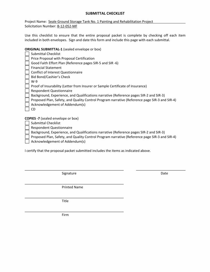
SUBMITTAL CHECKLIST
Project Name: Seale Ground Storage Tank No. 1 Painting and Rehabilitation Project Solicitation Number: B‐12‐052‐MF Use this checklist to ensure that the entire proposal packet is complete by checking off each item included in both envelopes. Sign and date this form and include this page with each submittal. ORIGINAL SUBMITTAL‐1 (sealed envelope or box)
Submittal Checklist Price Proposal with Proposal Certification Good Faith Effort Plan (Reference pages SIR‐5 and SIR ‐6) Financial Statement Conflict of Interest Questionnaire Bid Bond/Cashier’s Check W‐9 Proof of Insurability (Letter from Insurer or Sample Certificate of Insurance) Respondent Questionnaire Background, Experience, and Qualifications narrative (Reference pages SIR‐2 and SIR‐3) Proposed Plan, Safety, and Quality Control Program narrative (Reference page SIR‐3 and SIR‐4) Acknowledgement of Addendum(s) CD
COPIES ‐7 (sealed envelope or box)
Submittal Checklist Respondent Questionnaire Background, Experience, and Qualifications narrative (Reference pages SIR‐2 and SIR‐3) Proposed Plan, Safety, and Quality Control Program narrative (Reference page SIR‐3 and SIR‐4) Acknowledgement of Addendum(s)
I certify that the proposal packet submitted includes the items as indicated above.
Signature Date Printed Name Title Firm

P-1
Seale Ground Storage Tank No. 1 Painting and Rehabilitation Project SAWS Job No. 11-0107 Solicitation No. B-12-052-MF Opinion of Probable Construction Cost: $1,874,000.00 PRICE PROPOSAL
PROPOSAL OF a corporation a partnership consisting of an individual doing business as TO THE SAN ANTONIO WATER SYSTEM: Pursuant to Invitation for Competitive Sealed Proposals and Instructions to Respondents, the undersigned proposes to furnish all labor, materials, equipment and supervision as specified and perform the work required for the painting and rehabilitation of a 3.0 MG ground water storage tank at 254 Seale Road, San Antonio, TX, San Antonio Water System Job Number 11-0107, in accordance with the Plans and Specifications for the following prices to wit: BASE UNIT PRICES FOR:
ITEM NO
ITEM DESCRIPTION ( PRICE TO BE WRITTEN IN WORDS)
UNIT
QTY
UNIT PRICE (FIGURES)
TOTAL (FIGURES)
1
Seale GST No. 1 Painting and Rehabilitation - Furnish all materials, labor, equipment and superintendence for painting and rehabilitation of a 3.0 million gallon ground water storage tank and appurtenances including: pump station piping upgrades and painting; ASR and well piping painting; hazardous waste disposal and spoil removal; electrical upgrades, and additional site improvements in accordance with the contract plans and specifications; complete in place including contractor mobilization and demobilization. Dollars and Cents
LS
1
$XXXXXXX
$___________
2
Permit Allowance – Contractor shall include a $5,000.00 allowance in the proposal for reimbursement of charges incurred from Permit Fees associated with City of San Antonio Plan Review and Permitting. Five Thousand Dollars and Zero Cents
LS
1
$XXXXXXX
$_5,000.00__

P-2
3
Additional Work Allowance – Contractor shall include a $10,000.00 allowance in the proposal for reimbursement of required additional work authorized by the Owner and the Engineer, not shown on the drawings, described in the specifications or subsidiary to another bid item. Ten Thousand Dollars and Zero Cents
LS
1
$XXXXXXX
$_10,000.00__
Line Item ‘A’: SUB-TOTAL BASE ITEMS 1 – 3 $ ________________________
SUPPLEMENTARY UNIT PRICES FOR:
ITEM NO
ITEM DESCRIPTION ( PRICE TO BE WRITTEN IN WORDS)
UNIT
QTY
UNIT PRICE (FIGURES)
TOTAL (FIGURES)
S-1
Furnish all materials, labor, equipment and appurtenances for “Interior Grinding”, complete in place. Dollars and Cents
MH
100
$__________
$___________ S-2
Furnish all materials, labor, equipment and appurtenances for “Pit Welding”, complete in place. Dollars and Cents
SQ IN
100
$__________
$___________ S-3
Furnish all materials, labor, equipment and appurtenances for “Seam Welding”, complete in place. Dollars and Cents
LF
75
$__________
$___________ S-4
Furnish all materials, labor, equipment and appurtenances for “Pit Filling”, complete in place. Dollars and Cents
GAL
20
$__________
$___________

P-3
S-5
Furnish all materials, labor, equipment and appurtenances for “Additional Work”, complete in place. Dollars and Cents
MH
100
$__________
$___________ S-6
Furnish all materials, labor, equipment and appurtenances for “Additional Tank Ventilation/ Dehumidification”, complete in place. Dollars and Cents
WK
2
$__________
$___________ S-7
Furnish all materials, labor, equipment and appurtenances for “Sika-Flex 1A”, complete in place. Dollars and Cents
LS
1
$XXXXXXX
$___________ S-8
Furnish all materials, labor, equipment and appurtenances for “Replacement of Support Shelf Angles”, complete in place. Dollars and Cents
EA
48
$__________
$___________
Line Item ‘B’: SUB-TOTAL SUPPLEMENTARY ITEMS S-1 thru S-8
$ _______________________
See Next Page
P-4
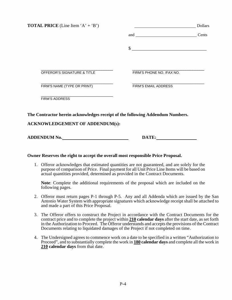
TOTAL PRICE (Line Item ‘A’ + ‘B’) Dollars and Cents $
_______________________________ _______________________________ OFFEROR’S SIGNATURE & TITLE FIRM’S PHONE NO. /FAX NO. _______________________________ _______________________________ FIRM’S NAME (TYPE OR PRINT) FIRM’S EMAIL ADDRESS
_______________________________ FIRM’S ADDRESS
The Contractor herein acknowledges receipt of the following Addendum Numbers. ACKNOWLEDGEMENT OF ADDENDUM(s): ADDENDUM No. DATE:
Owner Reserves the right to accept the overall most responsible Price Proposal.
1. Offeror acknowledges that estimated quantities are not guaranteed, and are solely for the purpose of comparison of Price. Final payment for all Unit Price Line Items will be based on actual quantities provided, determined as provided in the Contract Documents.
Note: Complete the additional requirements of the proposal which are included on the following pages.
2. Offeror must return pages P-1 through P-5. Any and all Addenda which are issued by the San
Antonio Water System with appropriate signatures which acknowledge receipt shall be attached to and made a part of this Price Proposal.
3. The Offeror offers to construct the Project in accordance with the Contract Documents for the
contract price and to complete the project within 210 calendar days after the start date, as set forth in the Authorization to Proceed. The Offeror understands and accepts the provisions of the Contract Documents relating to liquidated damages of the Project if not completed on time.
4. The Undersigned agrees to commence work on a date to be specified in a written “Authorization to
Proceed”, and to substantially complete the work in 180 calendar days and complete all the work in 210 calendar days from that date.

Rev. 06/10
P-5
PROPOSAL CERTIFICATION Accompanying this proposal is a Bid Bond or Certified or Cashier's Check on a State or National Bank payable to the Order of the San Antonio Water System for ____________________________________ dollars ($_____________________), which amount represents five percent (5%) of the total bid price. Said bond or check is to be returned to the bidder unless the proposal is accepted and the bidder fails to execute and file a contract within 10
calendar days after the award of t he C ontract, in which case the check shall become the property of said San Antonio Water System, and shall be considered as payment for damages due to delay and other inconveniences suffered by said San Antonio Water System due to the failure of the bidder to execute the contract. The San Antonio Water System reserves the right to reject any and all bids.
It is anticipated that the Owner will act on this proposal within 90 calendar days after the bid opening. Upon acceptance and award of the contract to the undersigned by the Owner, the undersigned shall execute standard San Antonio Water System Contract Documents and make Performance and Payment Bonds for the full amount of the contract within 10
calendar days after the award of the Contract to secure proper compliance with the terms and provisions of the contract, to insure and guarantee the work until final completion and acceptance, and the guarantee period stipulated, and to guarantee payment of all lawful claims for labor performed and materials furnished in the fulfillment of the contract.
It is anticipated that the Owner will provide written Authorization to Proceed within 30 days after the award of the Contract. The Contractor hereby agrees to commence work under this Contract within seven (7) calendar days after issuance by the SAWS of the written Authorization to Proceed. Under no circumstances shall the work commence prior to Contractor's receipt of SAWS issued, written Authorization to Proceed. Work shall be completed in full within 210 consecutive calendar days. The undersigned certifies that the bid prices contained in the proposal have been carefully checked and are submitted as correct and final. In completing the work contained in this proposal the undersigned certifies that b idder's practices and policies do not discriminate on the grounds of race, color, religion, sex or national origin and that the bidder will affirmatively cooperate in the implementation of these policies and practices. Signed: ___________________________________________
Company Representative ___________________________________________
Company Name ___________________________________________ ___________________________________________
Address Please return bidder's check to: ___________________________________________
Company Name ___________________________________________ ___________________________________________
Address
1
Rev 9/28/11 GFEP
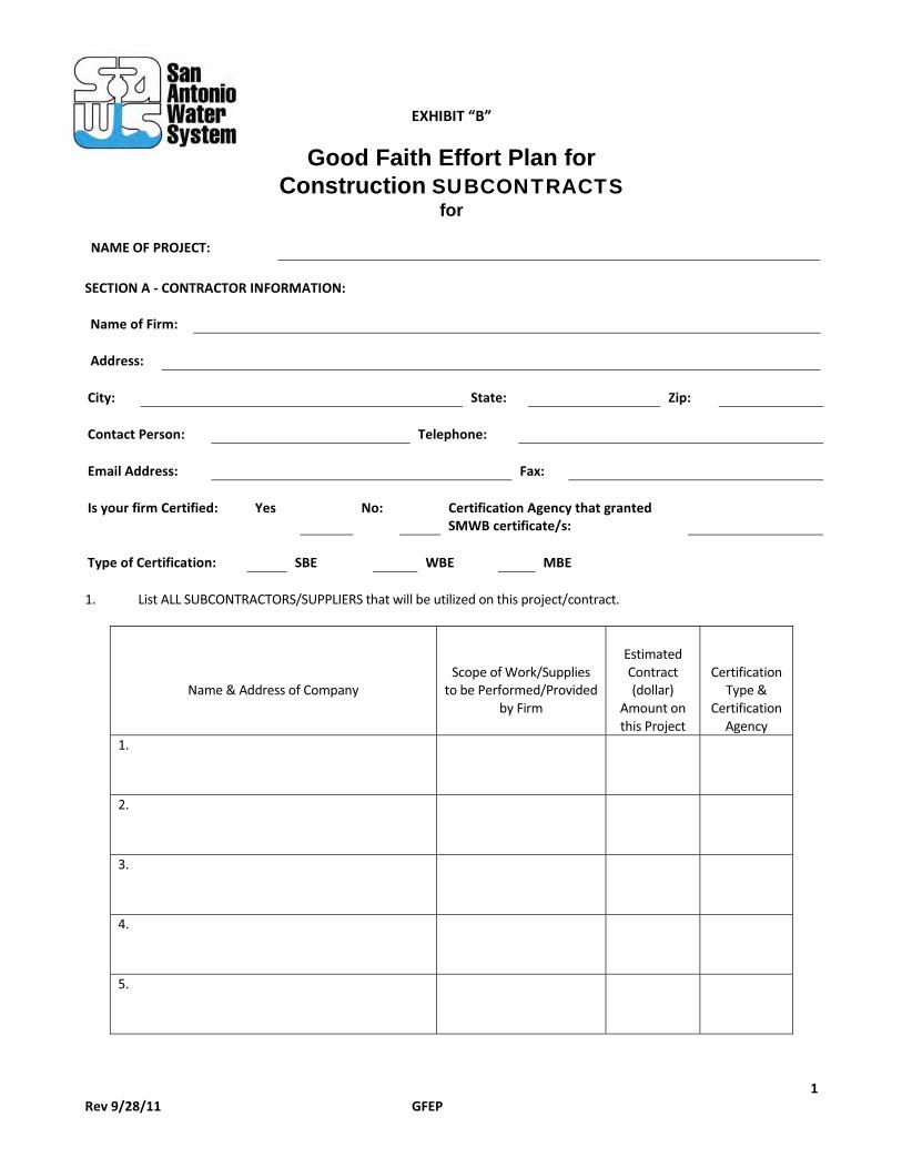
EXHIBIT “B”
Good Faith Effort Plan for Construction SUBCONTRACTS
for NAME OF PROJECT:
SECTION A - CONTRACTOR INFORMATION: Name of Firm: Address:
City: State: Zip: Contact Person: Telephone: Email Address: Fax: Is your firm Certified: Yes No: Certification Agency that granted
SMWB certificate/s: Type of Certification: SBE WBE MBE 1. List ALL SUBCONTRACTORS/SUPPLIERS that will be utilized on this project/contract.
Name & Address of Company
Scope of Work/Supplies to be Performed/Provided
by Firm
Estimated Contract (dollar)
Amount on this Project
Certification Type &
Certification Agency
1.
2.
3.
4.
5.

2
Rev 9/28/11 GFEP
SECTION B. – SMWB COMMITMENTS The SMWB goal on this project is _17
__%
1. The undersigned proposer has satisfied the requirements of the BID specification in the following manner (please check the appropriate space):
_____ The proposer is committed to a minimum of 17 %
SMWB utilization on this contract.
_____ The proposer, (if unable to meet the SMWB goal of _17%
), is committed to a minimum of _______% SMWB utilization on this contract. (If contractor is unable to meet the goal, please fill out Section C and submit documentation demonstrating good faith efforts).
2. Name and phone number of person appointed to coordinate and administer the SMWB requirements on this project.
Name: Title: Phone Number:
IF THE SMWB GOAL WAS MET, PROCEED TO AFFIRMATION AND SIGN THE GFEP. IF GOAL WAS NOT MET, PROCEED TO SECTION C. SECTION C – GOOD FAITH EFFORTS (Fill out only
if the SMWB goal was not achieved).
1. List all firms you contacted with subcontracting/supply opportunities for this project that will not be utilized for the contract by choice of the proposer, subcontractor, or supplier. Written notices to firms contacted by the proposer for specific scopes of work identified for subcontracting/supply opportunities must be provided to
subcontractor/supplier not less than five (5) business days prior to bid/proposal due date
Name & Address of Company
. The following information is required for all firms that were contacted of subcontracting/supply opportunities.
Scope of Work/Supplies to be Performed/Provided
by Firm
Is Firm SMWB
Certified?
Date Written Notice was Sent &
Method (Fax, Letter, E-Mail, etc.)
Reason Agreement was not reached?
1.
2.
3.
4.
5.
6.
7.
(Use additional sheets as needed)

3
Rev 9/28/11 GFEP
In order to verify a proposer’s good faith efforts, please provide to SAWS copies of the written notices to all firms contacted by the proposer for specific scopes of work identified in relation to the subcontracting/supply opportunities in the above named project. Copies of said notices must be provided to the SMWB Program Manager within five (5) business days after the response is due. Such notices shall include information on the plans, specifications, and scope of work. 2. Did you attend the pre-bid conference scheduled for this project? ____ Yes ____ No 3. List all SMWB listings or directories, contractor associations, and/or any other associations utilized to solicit SMWB
Subcontractors/suppliers. __________________________________________________________________________ __________________________________________________________________________
4. Discuss efforts made to define additional elements of the work proposed to be performed by SMWBs in order to increase the likelihood of achieving the goal: ___________________________________________________________________________ ___________________________________________________________________________ 5. Indicate advertisement mediums used for soliciting bids from SMWBs. (Please attach a copy of the advertisement(s): ___________________________________________________________________________ ___________________________________________________________________________
AFFIRMATION
I hereby affirm that the above information is true and complete to the best of my knowledge. I further understand and agree that, this document shall be attached thereto and become a binding part of the contract. Name and Title of Authorized Official: Name: _____________________________________________________________________________ Title: _____________________________________________________________________________ Signature:__________________________________________Date:_______________________ NOTE: This Good Faith Effort Plan is reviewed by SAWS Contracting Department. For questions and/or clarifications, please contact Marisol V. Robles, SMWB Manager, at 210-233-3420.

4
Rev 9/28/11 GFEP
DEFINITIONS:
Prime Consultant/Contractor: Any person, firm partnership, corporation, association or joint venture which has been awarded a San Antonio Water System contract. Subconsultants/contractor: Any named person, firm partnership, corporation, association or joint venture identified as providing work, labor, services, supplies, equipment, materials or any combination of the foregoing under contract with a prime consultant/contractor on a San Antonio Water System contract. Small, Minority and Woman Business (SMWB): All business structures Certified by the Small Business Administration, Texas State Comptroller’s Office, or the South Central Texas Regional Certification Agency that are 51% owned, operated, and controlled by a Small Business Enterprise, a Minority Business Enterprise, or a Woman-owned Business Enterprise. Small Business Enterprise (SBE): A business structure that is Certified by the Small Business Administration, Texas State Comptroller’s Office or the South Central Texas Regional Certification Agency as being 51% owned, operated and controlled by someone who is legally residing in or a citizen of the United States, and the business structure meets the U.S. Small Business Administration’s (SBA) size standard for a small business within the appropriate industry category Minority Business Enterprise (MBE): A business structure that is Certified by the Small Business Administration, Texas State Comptroller’s Office or the South Central Texas Regional Certification Agency as being 51% owned, operated, and controlled by an ethnic minority group member(s) who is legally residing in or a citizen of the United States. For purposes of the SMWB program, the following are recognized as minority groups:
a. African American – Persons having origins in any of the black racial groups of Africa as well as those identified as Jamaican, Trinidadian or West Indian.
b. Hispanic American – Persons of Mexican, Puerto Rican, Cuban, Spanish or Central or South American origin.
c. Asian-Pacific American – Persons having origins in any of the original peoples of the Far East, Southeast Asia, the
Indian subcontinent or the Pacific Islands.
d. Asian-Indian American – Persons whose origins are from India, Pakistan, Bangladesh or Sri Lanka.
e. American Indian/Native American – Persons having no less than 1/16 percentage origin in any of the American Indian Tribes, as recognized by the U.S. Department of the Interior’s Bureau of Indian Affairs and as demonstrated by possession of personal tribal role documents.
Women Business Enterprise (WBE): A business structure that is Certified by the Small Business Administration, Texas State Comptroller’s Office or the South Central Texas Regional Certification Agency as being 51% owned, operated and controlled by a woman or women who are legally residing in or citizens of the United States. African American Business Enterprise (AABE): A business structure that is Certified by the Small Business Administration, Texas State Comptroller’s Office or the South Central Texas Regional Certification Agency as being 51% owned, operated and controlled by African American minority group member(s) who are legally residing in or are citizens of the United States. Joint Venture: A limited association of two or more persons to carry out a single business enterprise for profit, for which purpose they combine their property, money, efforts, skills and knowledge.

5
Rev 9/28/11 GFEP
Contractor’s Payment to Sub-Contractors: The contractor will be required to report the actual payments to all subcontractors, utilizing the Sub-contracting Payment and Utilization Reporting (S.P.U.R.) System, in the time intervals and format prescribed by SAWS. This information will be utilized for SMWB participation tracking purposes. Any unjustified failure to comply with the committed SWMB levels may be considered breach of contract.
Web Submittal of Subcontractor Payment Reports: The Contractor is required to electronically submit monthly subcontractor payment information utilizing the Sub-contracting Payment and Utilization Reporting (S.P.U.R.) System, beginning with the first SAWS payment for services under the contract, and with every payment thereafter (for the duration of the contract). Electronic submittal of monthly subcontractor payment information will be accessed through a link on SAWS’ “Business Center” web page.
The Contractor and all subcontractors will be provided a unique log-in credential and password to access the SAWS subcontractor payment reporting system. The link may also be accessed through the following internet address: https://saws.smwbe.com/

SAWS Subcontractor Payment Compliance
SAWS utilizes the B2GNow subcontractor payment information application, a web‐based reporting system to track subcontractor payment compliance for prime contractors and consultants. Therefore, contractors and consultants are advised that the use of this system will be a requirement for this project. Listed below are the reporting requirements and link to the B2GNow portal on SAWS’ web site: Web Submittal of Subcontractor Payment Reports Each prime contractor/consultant will be contractually‐required to electronically submit monthly subcontractor payment information reports, utilizing the B2Gnow, beginning with the first SAWS payment for services under the contract, and with every payment thereafter (for the duration of the agreement). Electronic submittal of monthly subcontractor payment information will be accessed through a link on SAWS’ “Business Center” web page. Each contractor and subcontractor will be provided a unique log‐in credential and password to access the SAWS subcontractor payment reporting system. Training on the use of the system will be provided by SAWS and B2Gnow telephone support. Electronic submittals will require data entry of the amount paid to each subcontractor listed on the prime’s Good Faith Effort Plan after the prime receives payment from SAWS. Additional information on the B2GNow system can be found at the following website: http://www.b2gnow.com/ Rev. 6/30/11 B2G

SAN ANTONIO WATER SYSTEM
GENERAL CONDITIONS
CONTENTS
I. Contract Definitions
II. Legal Relationships & Responsibilities
III. Contract Documents & Bonds
IV. Contract Administration
V. Contract Responsibilities
VI. Contract Changes
VII. Contract Payments
VIII. Contract Completion Time
IX. Project Completion and Acceptance
X. Disputes
XI. Supplemental and Special Conditions

This page intentionally left blank.

SAN ANTONIO WATER SYSTEM
GENERAL CONDITIONS
ARTICLE I. CONTRACT DEFINITIONS:
Wherever in these General Conditions or in other parts of the Contract Documents, the following terms, or pronouns inplace of them are used, the intent and meaning shall be interpreted as follows:
1. ACPA - American Concrete Pipe Association.
2. ANSI - American National Standards Institute.
3. ASTM - American Society for Testing Materials.
4. AUTHORIZATION TO PROCEED - (Work Project Authorization) A written notice given by Owner toContractor establishing the date on which the Contract Time will commence to run and on whichContractor shall start to perform Contractor's obligations under the Contract Documents.
5. AWWA - American Water Works Association.
6. BIDDER - An individual, partnership, corporation, etc., submitting a proposal.
7. BOARD – Board of Directors of the San Antonio Water System.
8. CITY COUNCIL - The duly elected members of the council of the City of San Antonio, Texas.
9. CONDITIONAL LETTER OF APPROVAL - The date certified in writing by the Owner when theConstruction of the Project is sufficiently completed in accordance with the Contract Documents.
10. CONSTRUCTION OBSERVER/INSPECTOR - "COI", The authorized representative of the Ownerassigned by the Owner to observe and inspect any or all parts of the Project and the materials to be usedtherein.
11. CONSULTANT - A person registered as a professional engineer pursuant to Article 3271a, Vernon's TexasCivil Statutes employed to provide professional engineering services and having overall responsibility forthe design of a project or a significant portion thereof, together with administrative supervision of anysubconsultants Consultant may retain. The term "Consultant", unless the context clearly indicatesotherwise, means an engineer in private practice retained for a specific project under a contractualagreement with the Owner.
12. CONTRACT - The signatory Agreement (Standard Form) between the SAWS and the Contractorgoverning the furnishing of material and performance of the Work. The Contract will include the ContractDocuments.
13. CONTRACT DOCUMENTS - The Contract Documents consist of Bidding Documents such as: theAdvertisement or Invitation to Bid, the Instructions to Bidders, the Contractor's completed Bid Proposalform, the Addenda, the Contract, the Conditions of the Contract (General, Supplemental and SpecialConditions), the Plans, the Specifications, the Change Orders, the Payment and Performance Bonds.
(i) The Contract Documents form the complete CONTRACT, which represents the entire andintegrated agreement between the Owner and the Contractor and supersedes all prior negotiations,representations or agreements, either written or oral.
14. CONTRACT SUM - The total compensation payable to the Contractor for performing the Work as originally contracted or as subsequently adjusted by Change Orders.
15. CONTRACT TIME - The total time allowed the Contractor for completion of the Work. Contract Time
Rev. 06/10 - GC 1 -

will commence as per paragraph 8.1 and shall include the number of days set forth in the Contract plus anyextended days granted under the provisions of Paragraph 6.1.
16. CONTRACTOR - The individual, partnership, corporation, etc., contracting with the SAWS as Owner tocomplete the Work.
17. ENGINEER - The Vice President of Engineering or his duly authorized representative, either or both beinga duly authorized representative of the Owner.
18. CHANGE ORDER - A written order issued by the SAWS to the Contractor authorizing additions,deletions, or revisions to the Work to be performed by Contractor within the general scope of constructionservices outlined in the Contract Documents.
19. HAZARDOUS MATERIAL(s)/SUBSTANCE - Pursuant to Section 26.263 of the Water Code hazardousmaterial means any material/substance designated as such by the administrator of the EnvironmentalProtection Agency pursuant to the Comprehensive Environmental Response Compensation and LiabilityAct (42 U.S.C. Sec. 9601 et seq.) regulated pursuant to Section 311 of the Federal Clean Water Act (33U.S.C. Sec. 1321 et seq.) or designated by the Commission.
20. INSTRUCTIONS TO BIDDERS - Owner Instructions of a general nature outlining the duties andresponsibilities of a prospective bidder.
21. LABORATORY - The testing laboratories of the SAWS or any other testing laboratory that may bedesignated or approved by the Owner.
22. MAJOR BID ITEM - Any individual Bid Item submitted by Contractor that constitutes five percent (5%)minimum of the total Contract Sum proposed by the successful low bidder Contractor or, the dollar amountshown in the Special Conditions as constituting a "Major Bid Item", whichever is less. In spite of thegeneral criteria above, the Owner and Consultant reserve the right to identify or exclude specific Bid Itemsas being "Major", in the Special Conditions for each Project.
23. MINORITY BUSINESS ENTERPRISE - (hereinafter referred to as MBE) a corporation, partnership, soleproprietorship or any other such legal entity which is owned, operated and controlled by a minority groupmember(s) who, when combined, have 51 percent ownership. The minority group member(s) must haveoperational and managerial control, interest in capital and earnings commensurate with the percentage ofminority ownership. For purposes of the SMWBP, the following are recognized as minority groups:
.1 African-Americans - persons having origins in any of the black racial groups of Africa as well asthose identified as Jamaican, Trinidadian or West Indian.
.2 Hispanic Americans - persons of Mexican, Puerto Rican, Cuban, Spanish, or Central or SouthAmerica origin.
.3 American Indians - persons having no less than 1/16 percentage origin in any of the AmericanIndian tribes, as recognized by the U.S. Department of the Interior, Bureau of Indian Affairs and asdemonstrated by possession of personal tribal documents.
.4 Asian-Pacific Americans - persons having origins in any of the original peoples of the Far East,Southeast Asia, the Indian subcontinent or the Pacific Islands.
.5 Asian-Indian Americans - includes persons whose origins are from India, Pakistan, Bangladesh andSri Lanka.
.6 Disabled Individual - persons (1) with one or more disabilities as defined by the Americans withDisabilities Act (ADA) and amendments thereto, (2) having a record of such disabilities and (3)regarded as having such disabilities.
24. MUNICIPAL SEPARATE STORM SEWER SYSTEM (MS4) - A conveyance or system of conveyances(including roads with drainage systems, municipal streets catch basins, curbs, gutters, ditches, man-
Rev. 06/10 - GC 2 -

made channels or storm drains:
(i) Owned or operated by a State, City, town, borough, county, district association or other public body(created by or pursuant to State law) having jurisdiction over disposal of sewage, industrial waters,storm water or other wastes including special districts under State law such as a sewer district, floodcontrol district or drainage district or similar entity or a designated and approved managementagency under Section 208 of the Clean Water Act that discharges to water of the United States;
(ii) Designated or used for collection or conveying storm water.
(iii) Which is not part of a Publicly Owned Treatment Works (POTW) as defined at 40 CFR 122.2.
25. NEMA - National Electrical Manufacturers Association.
26. NFPA - National Fire Protection Association
27. NON-HAZARDOUS MATERIAL(s)/SUBSTANCES - Any material(s)/substance which is not designatedas hazardous pursuant to Definition 17 herein and the continued presence of such on the site is determinedby the Owner's representative not to be detrimental to the completion of the Project.
28. OWNER - See San Antonio Water System.
29. OWNER'S REPRESENTATIVE - The Vice President of Engineering or his duly authorized representative.
30. PAYMENT BOND - The security furnished by the Contractor through the Surety in the full amount of theContract Sum for the protection of all persons supplying labor and material in the prosecution of the Workwho properly follow statutory requirements for perfecting claims against such security." If the contractamount does not exceed $25,000, a Payment Bond is not required.
31. PERFORMANCE BOND - The security furnished by the Contractor through the Surety in the full amountof the Contract Sum as a guaranty that the Work will be faithfully performed and completed and that theOwner will be saved harmless from all costs and damages which the Owner may suffer by reason of theContractor's default or failure to perform the Work. If the contract amount does not exceed $25,000, aPerformance Bond is not required.
32. PLANS - The Plans, drawings, details and supplemental drawings, or reproductions thereof, produced andsealed by the Consultant and/or Engineer and approved by the Owner, showing the location, character,dimensions and details of the Work and which are a part of the Contract. Plans include standard detailsissued and sealed by the Engineer or his representative.
33. PROJECT - Work site and Work elements with all appurtenances and construction to be performed thereonunder the Contract.
34. PROPOSAL - The offer of the bidder, made out on the prescribed forms, giving prices for performing thework described in the plans and specifications.
35. SAMPLES - Physical examples furnished by the Contractor to Owner to illustrate intended or anticipatedmaterials, equipment or workmanship, and to assist Owner and Consultant in the establishment ofworkmanship and quality standards by which the Work will be judged.
36. SAN ANTONIO WATER SYSTEM - San Antonio Water System (SAWS) shall mean the San AntonioWater System Board of Trustees as established pursuant to Article 1115, Texas Revised Civil StatutesAnnotated and City of San Antonio Ordinance No. 75686. Whenever in this contract is found the term theSAWS or Owner the same shall, unless indicated otherwise, be understood to mean the San Antonio WaterSystem Board of Trustees, or its successors or any person or persons acting lawfully in an official capacity onbehalf of the SAWS at such time and within the power and authority specifically delegated to him or them bythis Contract.
37. SEPARATED CONTRACT - A contract in which the agreed contract price is divided into a separately statedagreed contract price for materials and a separately stated agreed contract price for skill and labor. If prices ofmaterials and labor are separately stated the fact that the charges are added together and a sum total given is
Rev. 06/10 - GC 3 -

irrelevant. Cost-plus contracts are generally regarded as separated contracts.
38. SEQUENCE OF CONSTRUCTION - The logical and proper order in which the Contractor shallaccomplish the Work by Owner directed stages and phases, as shown in the Contract Documents, unlessOwner orders otherwise by a properly executed Change Order.
39. SHOP DRAWINGS - Drawings, diagrams, illustrations, schedules, performance charts, brochures andother data which are furnished by the Contractor and prepared by Contractor, first-tier or subtiersubcontractors, manufacturer, supplier or distributor, and which illustrates and details some portion of theWork.
40. SMALL, MINORITY AND WOMAN BUSINESS - (hereinafter referred to as SMWB) includes all thosebusiness enterprises inclusive of sole proprietorships, partnerships, corporations and all other such legalentities that are either classified as small, or are owned, operated and controlled by minority groupmembers, women, or disabled individuals.
41. SMALL BUSINESS ENTERPRISE - (hereinafter referred to as SBE) a corporation, partnership, soleproprietorship or other such legal entity which is independently owned and operated and which is less than20 percent of the U.S. Small Business Administration (SBA) size standard for a small business, except incases where the reduced definition drops below $1 million average gross receipts (as based on three yearsof sales) or less than 100 employees.
42. SPECIFICATIONS - The specific instructions to the Contractor as to the requirements for materials,equipment, certain construction procedures, standards and quality of workmanship for the Work andperformance of related services and forming a part of the Contract.
43. SUBCONTRACTOR - The individual, firm or corporation, having a first tier subcontract with the prime orgeneral Contractor, subject to the review of qualifications by the Consultant and the Owner'sRepresentative, for the performance of a part of the Work. Subtier subcontractors must be identified by thesubcontractors and be similarly subject to the review of qualifications by the Consultant and the Owner'sRepresentative for the performance of a part of the Work.
44. SUBSTANTIAL COMPLETION - When construction of the project or a specified part thereof issufficiently completed in accordance with the Contract Documents so that the Project, or specified partthereof could be utilized for the Owner's purposes for which it is intended.
45. SUPERINTENDENT - The on project site representative of the Contractor authorized to communicatewith the SAWS's Construction Observer/Inspector ("COI"), pursuant to the terms of the contract. TheSuperintendent or his designee shall supervise and direct the construction Work.
46. SUPPLEMENTARY CONDITIONS - The part of the Contract Documents, which amends or supplementsthese General Conditions.
47. SURETY - The corporate body licensed to conduct business in the State of Texas that provides assurance thatthe Contractor, or his substitute will faithfully perform the Work covered by the Contract and make paymentof any due, unpaid, eligible labor and supply claims arising thereunder.
48. THD TEST METHOD - (TX DOT) Materials and Test Division manual outlining testing methods andprocedures.
49. UNDERGROUND FACILITIES - All pipelines, conduits, ducts, cables, wires, manholes, vaults, tanks,tunnels or other such facilities or attachments and appurtenances thereto, and any encasement containing suchfacilities which have been installed underground to furnish any of the following services or materials:electricity, gases, steam, liquid petroleum products, telephone or other communications, cable television,water, sewage and drainage removal, traffic or other control systems.
50. UNIT PRICE WORK - Work to be paid for by Owner on the basis of Contractor quoted unit prices in theBid Proposal based upon Owner estimated quantities.
51. WOMAN BUSINESS ENTERPRISE - (hereinafter referred to as WBE) a corporation, partnership, sole
Rev. 06/10 - GC 4 -
proprietorship or any other such legal entity which is owned, operated and controlled by women who, whencombined, have 51 percent ownership. The women must have operational and managerial control, interestin capital and earnings commensurate with the percentage of women ownership.
52. WORK - The entire completed construction or the various separately identifiable parts thereof required tobe furnished under the Contract Documents. Work is the result of Contractor performing services,furnishing labor and furnishing and incorporating materials and equipment into the construction, all asrequired by the Contract Documents.
53. WRITTEN NOTICE - Shall be considered to have been duly given if delivered in person to an authorizedrepresentative of the Contractor or Owner, or to an officer of the corporation for whom it is intended, or ifdelivered at, or sent by registered or certified mail to the last business address known to the person whogives the notice.
ARTICLE II. LEGAL RELATIONSHIPS AND RESPONSIBILITIES
2.1 LEGAL RESPONSIBILITIES - The Contractor in the performance of the Work shall comply with allpertinent Ordinances of the City of San Antonio (COSA), Regulations of the San Antonio Water System(SAWS), Laws of the State of Texas, and of the United States, including Rules and Regulations of theUnited States Department of Labor, pertaining to Occupational Safety and Health Administration standardsas presently existing or as may hereinafter be modified or amended.
.1 Where construction projects cross or run along state highways, the Contractor shall comply withgoverning Texas Department of Transportation Regulations as outlined in State Permits for eachcrossing. In cases where State Regulations do not apply, City Regulations shall be binding.
.2 Where construction projects cross or run along county roads, the Contractor shall comply withgoverning Bexar County Public Works Regulations as outlined in the County Permit for eachcrossing.
2.2 GENERAL UNDERSTANDING - Contractor at his own cost and expense shall furnish all supervision,tools, implements, machinery, labor, materials and accessories, such as are necessary and proper for thepurpose, and secure all required permits and licenses, and shall at his own cost and expense construct, buildand complete, in a good, first class, substantial and workmanlike manner, the structures, work andimprovements herein described and/or referred to in the Contract Documents.
2.3 INDEMNIFICATION - Contractor shall protect the public, SAWS, and COSA fully by taking reasonableprecaution to safeguard persons from death or bodily injury and to safeguard property of any naturewhatsoever from damage. Where any dangerous condition or nuisance exists in and around constructionsites, equipment and supply storage areas, and other areas in anyway connected with the performance ofthis contract, the Contractor shall provide and maintain reasonable warning of such danger or nuisance.The Contractor shall not create excavation, obstructions, or any dangerous condition or nuisance of anynature whatsoever in connection with the performance of this contract unless necessary to its performance,and in that event the Contractor shall provide and maintain at all times reasonable means of warning of anydanger or nuisance created. The duties of the Contractor in this section shall be nondelegable, and theContractor's compliance with the specific recommendations and requirements of the San Antonio WaterSystem or the City of San Antonio as to the means of warning shall not excuse the Contractor from thefaithful performance of these duties should such recommendations and requirements not be adequate orreasonable under the circumstances.
In order to protect SAWS and COSA the Contractor's failure to perform any of the foregoing duties or anyof the terms of this contract, the Contractor shall indemnify and save harmless SAWS, COSA and theiragents and employees from all losses, damages, judgments, decrees, and expenses or costs of any naturewhatsoever, arising out of or in anyway connected with any claims or actions at law or in equity, broughtagainst SAWS, COSA and their agents and employees for the death or injury to persons or for damage toproperty caused, or allegedly caused, by any willful acts, negligence, nuisance, or breach of any term orcondition of this contract in connection with work to be performed pursuant to said contract, by theContractor, his agents, subcontractors, or employees. The Contractor shall furthermore indemnify and saveharmless SAWS and COSA and their agents and employees from all demands of subcontractors, workmen,
Rev. 06/10 - GC 5 -
materialmen, or suppliers of machinery and parts thereof, equipment, power tools, and supplies incurred inconnection with work to be performed under this contract. Property of any description, including propertySAWS and COSA, which shall be damaged in the performance of this contract by the Contractor, hisagents, employees, subcontractors or their employees and subcontractors shall be restored to its conditionprior to damage by the Contractor at the Contractor's expense.
SUCH INDEMNITY SHALL APPLY WHERE THE CLAIMS, LOSSES, DAMAGES, CAUSES OFACTION, SUITS, JUDGEMENTS, DECREES, OR LIABILITY ARISE IN PART FROM THENEGLIGENCE OF SAWS OR COSA. IT IS THE EXPRESSED INTENTION OF THE CONTRACTOR,SAWS AND COSA THAT THE INDEMNITY PROVIDED FOR IN THIS PARAGRAPH ISINDEMNITY BY CONTRACTOR, TO INDEMNIFY AND PROTECT SAWS AND COSA FROM THECONSEQUENCES OF THEIR OWN NEGLIGENCE, WHERE THE NEGLIGENCE IS ACONCURRING CAUSE OF THE INJURY, DEATH, OR DAMAGE. FURTHERMORE, THEINDEMNITY PROVIDED FOR IN THIS PARAGRAPH SHALL HAVE NO APPLICATION TO ANYCLAIM, LOSS, DEATH OR DAMAGE RESULTS FROM THE SOLE NEGLIGENCE OF SAWS ANDCOSA UNMIXED WITH THE FAULT OF ANY PERSON OR ENTITY.
In any claims against SAWS or COSA or their agents or employees by CONTRACTOR, any employee ofCONTRACTOR, any subcontractor, anyone directly or indirectly employed by CONTRACTOR, or anysubcontractor or anyone for whose acts any of them may be liable, the indemnification obligation underthis paragraph shall not be limited in any way by any limitation on the amount or type of damages,compensation or benefits payable by or for CONTRACTOR or any subcontractor under workers'compensation acts, disability benefit acts of other employer's benefit acts.
2.4 ROYALTIES AND PATENTS - The Contractor shall pay all royalties and license fees, and defend allsuits or claim for infringement of any patent rights and shall save the SAWS harmless from loss on accountthereof, except that the SAWS shall be responsible for all such royalties and license fees and loss when aparticular design or process, or the product of a particular manufacturer or manufacturers is specified;provided, however, if the Contractor has reason to believe the design, process or product specifiedconstitutes an infringement of a patent, he shall be responsible for such royalties, license fees and lossunless he promptly gives such information to the Owner.
2.5 NO WAIVER OF SAWS RIGHTS - Unless specifically and unambiguously set out in the ContractDocuments at the time of bid opening, no observation/inspection or approval by said Owner or any COI,officer or employee of the Owner, or any order, measurement or certificate by said Owner, or any estimateor payment by the Owner for any part of said Work, or material or method or equipment, or any extensionof time, or any possession of the Work, at any time shall operate as a waiver of any provision or obligationof this Contract or any right or power herein given or reserved to said Owner, or of any right to claim anyindemnity or damages for patent or latent defects in the work or otherwise as herein provided for; nor shallany Owner waiver of any Contractor breach of this Contract be deemed as a waiver of any other orsubsequent Contractor breach; and every Owner right or remedy under the Contract Documents shall becumulative, and in addition to all other Owner rights and remedies.
2.6 INTEREST IN SAWS CONTRACT PROHIBITED - No officer or employee of the SAWS shall have afinancial interest, direct or indirect, in any contract with the SAWS, or shall be financially interested,directly, in the sale to the SAWS of any land, materials, supplies or service, except on behalf of the SAWSas an officer or employee. This prohibition extends to the City Public Service Board, City of San Antonio,and City boards and commissions other than those, which are purely advisory.
2.7 EQUAL EMPLOYMENT OPPORTUNITY REQUIREMENTS/NONDISCRIMINATION CLAUSE -TheSan Antonio Water System highly encourages contractors to implement Affirmative Action practices intheir employment programs. This means contractor should not discriminate against any employee orapplicant for employment because of race, color, national origin religion, sex, age, handicap or politicalbelief or affiliation.
2.8 SMALL, MINORITY, AND WOMEN BUSINESS PROGRAM(SMWBP) REQUIREMENTS - The SanAntonio Water System highly encourages contractors to form joint ventures and/or provide subcontractopportunities to small, minority and woman business (SMWB) firms. The San Antonio Water SystemGood Faith Effort Plan will be used to report small, minority, and woman firm participation. This Planwill be submitted as part of the bid package and will be reflected as part of the total construction contract
Rev. 06/10 - GC 6 -
documents.
2.9 STATE SALES TAX - The Owner qualifies for exemption from state and local sales tax and will furnishthe Contractor with a tax exemption certificate. It is the Contractor's responsibility to claim exemptionfrom payment of applicable state and local sales taxes by complying with such procedures as may beprescribed by the State Comptroller of Public Accounts. The Contract separates the cost of materials andtangible equipment from skill, labor and other associated costs of construction. This is in accordance withthe Texas Tax Code to allow tax exemption on the Contract price for materials. Certain constructionequipment that is owned or rented by the CONTRACTOR may be subject to State and Local Sales Tax.
ARTICLE III. CONTRACT DOCUMENTS & BONDS
3.1 PLANS AND SPECIFICATIONS - The Plans and the accompanying Specifications are essential parts ofthe Contract and a requirement occurring in one is as binding as though occurring in all. They are intendedto be cumulative and complementary and to provide for a complete Work. In cases of disagreement,figured dimensions shall govern over scaled dimensions, detailed Plan Drawings and accompanyingnotations shall govern over General Plan Drawings, and Special Conditions shall govern overSpecifications, Plan Drawings and General Conditions.
3.2 INTENT OF THE CONTRACT DOCUMENTS is to describe a functionally complete Project (or integralcomponent part thereof) to be constructed in accordance with the Contract Documents. Any work,materials or equipment that may reasonably be inferred from the Contract Documents as being required toproduce the intended result will be supplied by Contractor whether or not specifically called for by SAWSor it's Consultant. When words which have a well-known technical or trade meaning are used to describework, materials or equipment such words shall be interpreted in accordance with that meaning. Wherephrases "directed by", "ordered by" or "to the satisfaction of" "the Consultant" or "the SAWS'sConstruction Observer/Inspector" (COI) occur, it is to be understood that the directions, orders, orinstructions to which they relate are within the scope of, and authorized by the Contract Documents.Reference to standard specifications, manuals or codes of any technical society, organization orassociation, or to the Laws or Regulations of any governmental authority, whether such reference bespecific or by implication, shall mean the latest standard specification, manual, code or Laws orRegulations in effect at the time of opening of Bids except as may be otherwise specifically stated.
3.3 DISCREPANCY IN CONTRACT DOCUMENTS - If, during the performance of the Work, Contractorfinds a conflict, error or discrepancy in the Contract Documents, Contractor shall so report to Consultant orOwner in writing at once and before proceeding with the Work affected thereby and shall obtain a promptwritten interpretation or clarification from Consultant; however, Contractor shall not be liable to SAWS orConsultant for failure to report any conflict, error or discrepancy in the Contract Documents unlessContractor had actual knowledge thereof or should reasonably have known thereof.
3.4 PLANS AND SPECIFICATIONS AT THE WORK SITE - The Contractor shall maintain at the Work siteat least one copy of all Plans Specifications, Addenda, approved Shop Drawings and Change Orders, ingood order and marked to record all changes to the Plans and/or existing physical conditions made duringconstruction.
.1 RECORD DRAWINGS - Each month as the Work progresses and before monthly payment and thefinal payment to the Contractor, the Contractor who has control of the Work and is in a position toknow how the Project was constructed, shall submit to the Consultant, within 10 days after FinalAcceptance, a set of clearly marked Plans and related documents suitable for Consultant's use inpreparing Owner's final "Record Drawings" on reproducible mylar for the SAWS's permanent file.
3.5 PERFORMANCE BOND - CONTRACTOR shall furnish Performance Bond in favor of SAWS in anamount equal to 100% of the total construction cost under this Contract. Total construction cost aredefined as the entire cost of materials and their installation, and include, but are not limited to, the cost oflabor, equipment, supplies, materials and additional construction costs. The Performance Bond shall: (1)guarantee the completion of the entire construction herein identified in conformity with the Plans andSpecification approved by SAWS, and (2) guarantee the work against defects in workmanship andmaterials for a period of twenty four (24) months after acceptance of the work by the San Antonio WaterSystem. The bond shall have corporate Sureties that are licensed to conduct business in Texas. Thecontractor agrees that the following shall apply to bonds provided by a surety:
Rev. 06/10 - GC 7 -
If any bond is in an amount in excess of 10 percent of the surety company's capital and surplus, the SanAntonio Water System shall require, as a condition to accepting the bond, written certification that thesurety company has reinsured the portion of the risk that exceeds 10 percent of the surety company's capitaland surplus with one or more reinsurers who are duly authorized, accredited, or trusteed to do business inthis state. The amount reinsured by any reinsurer may not exceed 10 percent of the reinsurer's capital andsurplus.
If the amount of the bond exceeds $100,000, the surety must also:
(1) hold a certificate of authority from the United States secretary of the treasury to qualify as a suretyon obligations permitted or required under federal law; or
(2) have obtained reinsurance for any liability in excess of $100,000 from a reinsurer that is authorizedand admitted as a reinsurer in this state and is the holder of a certificate of authority from the UnitedStates secretary of the treasury to qualify as a surety or reinsurer on obligations permitted orrequired under federal law.
If the surety on any bond furnished by the CONTRACTOR to the BOARD is declared bankrupt orbecomes insolvent, or has its right to do business revoked in the State of Texas, then the CONTRACTORwill have ten (10) days to substitute another bond and surety therefor which shall be acceptable to SAWSand which shall be at the expense of the CONTRACTOR.
3.6 PAYMENT BOND - CONTRACTOR shall furnish Payment Bond in favor of SAWS in an amount equalto 100% of the total construction cost under this Contract. Total construction costs are defined as the entirecost of materials and their installation, and include, but are not limited to, the cost of labor, equipment,supplies, materials and additional construction costs. The Payment Bond shall be security for the paymentof all persons supplying labor and material in the prosecution of the Work provided for in the ContractDocuments. The contractor agrees that the following shall apply to bonds provided by a surety:
If any bond is in an amount in excess of 10 percent of the surety company's capital and surplus, the SanAntonio Water System shall require, as a condition to accepting the bond, written certification that thesurety company has reinsured the portion of the risk that exceeds 10 percent of the surety company's capitaland surplus with one or more reinsurers who are duly authorized, accredited, or trusteed to do business inthis state. The amount reinsured by any reinsurer may not exceed 10 percent of the reinsurer's capital andsurplus.
If the amount of the bond exceeds $100,000, the surety must also:
(1) hold a certificate of authority from the United States secretary of the treasury to qualify as a suretyon obligations permitted or required under federal law; or
(2) have obtained reinsurance for any liability in excess of $100,000 from a reinsurer that is authorizedand admitted as a reinsurer in this state and is the holder of a certificate of authority from the UnitedStates secretary of the treasury to qualify as a surety or reinsurer on obligations permitted orrequired under federal law.
The bonds shall have corporate Sureties that are licensed to conduct business in Texas. If the surety on anybond furnished by the CONTRACTOR to the BOARD is declared bankrupt or becomes insolvent, or hasits right to do business revoked in the State of Texas, then the CONTRACTOR will have ten (10) days tosubstitute another bond and surety therefore which shall be acceptable to SAWS and which shall be at theexpense of the CONTRACTOR.
3.7 CONTRACTOR AND SURETIES STILL BOUND - No assignment, transfer or subletting, without thewritten consent of SAWS, and no order of SAWS for or approval of any alterations or modifications in saidSpecifications, Plans, or Work, and no change in the requirements or order for extra work made by theSAWS as provided in this Contract, shall ever in any manner release or diminish the responsibility ofContractor or any Surety on any bond of Contractor, but on the contrary, such responsibility shall extend toand comprehend all such changes and other matters. If any Surety upon any bond furnished in connectionwith the Contract becomes insolvent, or otherwise not authorized to do business in this State, theContractor shall within ten (10) days furnish equivalent substitute forms of security while seekingsubstitute bonding, to protect the interests of the SAWS and of persons supplying labor or materials in the
Rev. 06/10 - GC 8 -
prosecution of the Work contemplated by the Contract, or may be liable for breach of Contract and defaulttermination.
ARTICLE IV. CONTRACT ADMINISTRATION
4.1 GENERAL ADMINISTRATION - (Plans and Specifications by Consultant). The Consultant will providegeneral administration of the Contract during construction in accordance with the Consultant's scope ofwork as defined in the Consultant's Contract with the SAWS.
.1 The Consultant has the authority to act on behalf of the Owner to the extent provided in theConstruction Contract Documents. The Consultant will advise and consult with the Owner. TheOwner's instruction to the Contractor may be issued through the Consultant but the Owner reservesthe right to issue instructions directly to the Contractor through other designated SAWSrepresentatives. Contractor understands that SAWS may modify the authority of such Consultant asprovided in the terms of its contract relationship with the Consultant, and the Owner shall, in suchevent, be vested with powers formerly exercised by such Consultant, provided written notice of suchmodification shall be immediately served on the Contractor. Nothing herein shall authorizeindependent agreements between Contractor and such Consultant, nor shall the Consultant bedeemed to have a legal relationship with the Contractor.
.2 All oral instructions shall be confirmed expeditiously in writing with copies furnished theConsultant, the Owner's designated representatives, and the Contractor by the party issuing the oralinstruction.
.3 Upon the Consultants written recommendation, the Owner's Representative shall have the finalauthority to reject Work performed by the Contractor which does not meet the requirements of thecontract, and to order such Work repaired, removed, or replaced in accordance with Paragraph 5.11.
4.2 GENERAL ADMINISTRATION - (Plans and Specifications by Engineer)
.1 The Engineer shall confirm all oral instructions to the CONTRACTOR expeditiously in writing.
.2 The Engineer shall have the authority to reject Work performed by the Contractor which does notmeet the requirements of the Contract, and to order such Work repaired, removed, or replaced inaccordance with Paragraph 5.11.
4.3 ACCESS TO AND OBSERVATION/INSPECTION OF THE WORK - (Plans and Specifications byConsultant). The Contractor shall provide sufficient, safe and proper facilities at all reasonable times forthe observation/inspection of the Work by the duly authorized representative of the Owner. The Consultantand the Owner will make visits to the site at intervals appropriate to the various stages of construction toobserve the progress of the executed Work and to determine if the Work is proceeding in accordance withthe Contract Documents.
.1 On the basis of such visits and on-site observations as an experienced and qualified designprofessional, Consultant will keep Owner informed of the progress of the Work and will guardOwner against defects and deficiencies in the Work which are the responsibility of the Contractor toprevent and/or cure.
.2 No Approval of any phase of the construction Project by any of the Owner's representatives orobserver/inspectors shall relieve the Contractor from full compliance with the Contract Documentsregarding the ultimate Work product. Any additional cost, damages, or delays occasioned by patentor latent defects in the Work, and/or failure to meet the requirements of the Contract Documents, atany Project phase, shall be borne by the Contractor.
4.4 ACCESS TO AND OBSERVATION/INSPECTION OF THE WORK - (Plans and Specifications byEngineer) - The Contractor shall provide sufficient, safe and proper facilities at all reasonable times for theobservation/inspection of the Work by the duly authorized representative of the Owner. The Engineer willmake visits to the site at intervals appropriate to the various stages of construction to observe the progressof the executed Work and to determine if the Work is proceeding in accordance with the ContractDocuments.
Rev. 06/10 - GC 9 -

.1 No Approval of any phase of the construction Project by any of the observer/inspectors shall relievethe Contractor from full compliance with the Contract Documents regarding the ultimate Workproduct. Any additional cost, damages, or delays occasioned by patent or latent defects in theWork, and/or failure to meet the requirements of the Contract Documents, at any Project phase, shallbe borne by the Contractor.
4.5 ASSIGNMENTS AND SUBLETTING - Contractor shall not assign, transfer, convey, sublet or otherwisedispose of this Contract, or any portion thereof, or any right, title or interest in, to or under the same,without the previous written consent of the Owner. Contractor shall not assign by power of attorney orotherwise any of the monies or other considerations to become due and payable by the Owner under thisContract, without the previous written consent of the Owner. The Contractor shall notify the Owner, bywritten notification by certified mail to the Director of Finance - SAWS, that such assignment, transfer,conveyance or subletting, or other disposition of this contract or any portion thereof, or any right, title orinterest, in, to or under the same, is contemplated. If the Contractor does not receive written approval ofsuch contemplated action by the Owner, through the Director of Finance, within thirty days of receipt ofsuch initial request by the Director, such contemplated assignment, transfer, conveyance or subletting, orother disposition of this contract or any portion thereof, or any right, title or interest in, to, or under thesame, shall be deemed disapproved. In no event shall the Owner be liable in excess of the consideration ofthis Contract in the case of any such assignment, transfer, conveyance or subletting of the Work orperformance which is subject hereof.
.1 The Owner reserves the right to withhold any monthly payment hereafter provided for in the eventof an assignment or subletting of a portion of the work without the previous consent and knowledgeof the Owner and by reserving such right, the Owner shall not be deemed to have waived its right todeclare a full breach of this Contract for Contractor's failure to comply with provisions hereof, suchremedy being alternative only and exercisable at the option of the Owner.
4.6 SUBCONTRACTORS - The Contractor shall upon executing the Contract, notify the Owner in writing ofthe names of all proposed first tier subcontractors for the Work. This should include the SMWBsindentified in the Good Faith Effort Plan
.1 SUBCONTRACTUAL RELATIONS:
By an appropriate written agreement, the Contractor shall require each Subcontractor, to the extentof the Work to be performed by the Subcontractor, to be bound to the Contractor by the terms of theContract Documents, and to assume toward the Contractor all the obligations and responsibilitieswhich the Contractor, by these Documents, assumes toward the Owner and the Consultant. Saidagreement shall preserve and protect the rights of the Owner and the Consultant under the ContractDocuments with respect to the Work to be performed by the Subcontractor so that thesubcontracting thereof will not prejudice such rights, and shall allow to the Subcontractor, thebenefit of all rights, remedies and redress against the Contractor that the Contractor, by theseDocuments, has against the Owner. Where appropriate, the Contractor shall require eachSubcontractor to enter into similar agreements with his Sub-subcontractors. The Contractor shallmake available to each proposed Subcontractor, prior to the execution of the Subcontract, copies ofthe Contract Documents to which the Subcontractor will be bound by this paragraph and identify tothe Subcontractor any terms and conditions of the proposed Subcontract which may be at variancewith the Contract documents. Each Subcontractor shall similarly make copies of such Documentsavailable to his Sub-subcontractor.
4.7 SEPARATE CONTRACTS
.1 The Owner reserves the right to let other contracts in connection with this Work. The Contractorshall afford other contractors reasonable opportunity for the introduction and storage of theirmaterials and the execution of their work and shall properly connect and coordinate his Work withtheir work.
.2 When separate contracts are awarded for different portions of the Project, "the Contractor" in theContract Documents in each case shall be the Contractor who executes each separate Contract. ThisContractor shall properly connect and coordinate his Work with the work of other contractors. If
Rev. 06/10 - GC 10 -

any part of this Contractor's Work depends for proper execution or proper results on the work of anyother separate contractor, this Contractor shall inspect and promptly report in writing to theConsultant and SAWS "COI " any discrepancies or defects he may find in the work of any separatecontractor that render it unsuitable to achieve proper connection, execution and results. Failure ofthis Contractor to so inspect and report obvious discrepancies or defects shall constitute anacceptance of the other contractor's work as fit and proper to receive this Contractor's Work, exceptas to defects which may develop in the other separate contractor's work after the execution of thisContractor's work.
.3 Should this Contractor negligently cause damage to the work or property of any separate contractoron the Project, this Contractor shall, upon due notice, endeavor to settle with such other contractorby agreement. A reciprocal clause shall be placed in the Contract Documents between the SAWSand the separate Contractor if involving other SAWS work. If such separate contractor sues theSAWS and/or it's agents on account of any damage alleged to have been so sustained, the SAWSand/or it's agents shall notify this Contractor who shall defend the SAWS's and/or it's agents'interests and Contractor's own interests in such proceedings and pay all attorney fees, and costs inconnection therewith, and if any judgment against the SAWS results therefrom, this Contractor shallpay or satisfy that judgment.
4.8 CONTRACT TERMINATION
.1 TERMINATION BY CONTRACTOR - If the Work is stopped by SAWS for a period of ninety(90) consecutive days (working or calendar days depending upon the type of Contract entered into)under an order of any court or other public authority having jurisdiction, or as a result of an act of ahigher governmental authority, such as a declaration of a national emergency making materialsunavailable, through no act or fault of the Contractor or a subcontractor or their agents or employeesor any other persons performing any of the Work under a contract with the Contractor, then theContractor may upon ten (10) additional days written notice to the SAWS and the Consultant,terminate the Contract and recover from the Owner payment for all Work previously executed andfor any loss sustained upon any materials, equipment, tools, construction equipment and machinery,including reasonable profit and damages related to the Work stoppage. If the Work is recommencedduring the ten (10) day notice period, the Contractor may not terminate the Contract.
.2 TERMINATION BY OWNER - If the Contractor is adjudged as bankrupt, or if he makes a generalassignment for the benefit of his creditors, without the consent of the SAWS or if a receiver isappointed on account of his insolvency, or if he persistently or repeatedly refuses or fails, except incases for which extension of time is provided, to supply enough properly skilled workmen or propermaterials, or persistently disregards laws, ordinances, rules, regulations or orders of any publicauthority having jurisdiction pertaining to the Work, or otherwise is guilty of a substantial violationof a provision of the Contract Documents warranting Owner default of Contractor, then the Ownermay, without prejudice to any right or remedy and after giving the Contractor and his Surety, if any,ten (10) days written notice, terminate the employment of the Contractor and/or take possession ofthe site and of all materials, and may upon order of a court of competent jurisdiction take possessionof equipment, tools, construction equipment and machinery thereon owned by the Contractor.Should the Surety fail to pursue completion of the Work with reasonable speed, the Owner mayarrange for completion of the Work and deduct the cost thereof from the unpaid Contract sumremaining, including the cost of additional Owner administration and Consultant services madenecessary by such default or neglect, in which event no further payment shall then be made by theOwner until all cost of completing the Work shall have been paid.
In the event that Owner shall be prevented from completing performance of its obligations underthis Contract by an act of God or other occurrence whatsoever which is beyond the control ofOwner, then Owner shall be excused from any further performance of its obligation andundertakings.
.3 If the unpaid balance of the Contract sum exceeds the costs of finishing the Work, includingcompensation for the Consultant's additional services made necessary thereby, such excess shall bepaid to the Contractor. If such costs exceed the unpaid balance, the Contractor or his surety shallpay the difference to the Owner. This obligation for payment shall survive the termination of theContract.
Rev. 06/10 - GC 11 -

4.9 CONTRACTOR BID SUSPENSION POLICY
.1 INTRODUCTION - The San Antonio Water System (SAWS) through its Board of Trusteesroutinely contracts with private businesses to build, maintain and repair SAWS structures, vehicles,equipment, property and other assets. SAWS desires to receive quality service and performance at afair price for each construction services, material, supply, and equipment contract awarded underSection V of SAWS Purchasing and Contracting Policy.
Occasionally, it appears to SAWS that the quality of service or performance required by the contractdocuments is not provided. Therefore SAWS requires a policy and a process to addressnonperformance by contractors and, if necessary, to suspend certain contractors from furthercontract awards for a period of time.
The purpose of this policy is to establish a procedural framework to suspend a contractor fromconsideration for award of contracts with SAWS, based on a determination that the contractor hasnot met the performance standards as outlined in Section 4.9.4, Reasons for Contractor Suspension.
Staff will implement procedures consistent with this Section 4.9 to address service quality andperformance issues. These procedures will include adequate safeguards, reviews and appeals toinsure that contractors being considered for suspension are provided ample opportunity fordiscussion, communication, and corrective actions prior to being suspended.
The term “contractor” as used herein means a construction contractor, subcontractor, vendor,supplier, materialman and any other person or entity supplying labor and/or material to SAWS on acontract basis.
"SAWS Management Officials" means SAWS personnel who are at the Manager level or above andwho are involved in the supervision, review or acceptance of services, work or materials providedby contractors under contract with SAWS.
.2 CREATION OF CONTRACTING COMMITTEE - There shall be a standing ContractingCommittee comprised of SAWS staff appointed by the President/Chief Executive Officer of SAWS.At least one Committee member will be a Vice President of SAWS and all other Committeemembers will be Managers or higher. The members of the Committee hearing the complaint will beSAWS Management Officials not directly involved with the contractor being considered for bidsuspension. If a standing Contracting Committee member has been involved in the day-to-dayadministration or supervision of a contract with a contractor being reviewed by the Committee, suchCommittee member will not serve on the Committee with regard to a complaint or appeal affectingthat contractor. The President/CEO may either appoint a substitute or the Committee may proceedwith fewer members, but in no event will there be less than three members available at anyCommittee meeting to hear information presented. The members of the Committee hearing thecomplaint will be SAWS Management Officials not directly involved with the contractor beingconsidered for bid suspension.
.3 ADMINISTRATIVE PROCEDURES - Subject to applicable laws, regulations and this policy,SAWS' legal department will develop the Administrative and Operational Procedures for ContractorBid Suspension Hearings and Appeals as outlined in "Exhibit B" at the rear of these GeneralConditions. The Contracting Committee may recommend changes to the Administrative andOperational Procedures. Changes to the Administrative and Operational Procedures must beapproved by the President/CEO.
.4 REASONS FOR CONTRACTOR SUSPENSION:
The Contracting Committee may suspend a contractor for any of the following reasons:
a. Contractor's failure to satisfy contract obligations;
b. Contractor's unsatisfactory safety performance;
Rev. 06/10 - GC 12 -

c. Contractor's failure to meet schedules or deadlines established in a contract with SAWS;
d. Contractor's failure to meet specifications or plan requirements;
e. Contractor's failure to staff a project as specified in contract documents;
f. Contractor's provision of inaccurate information in bid documents;
g. Contractor's failure to provide change order documentation specified in contract documents;
h. Contractor's failure to comply with warranty obligations;
i. Contractor's failure to satisfy all contract obligations to subcontractors, materialmen andlaborers on SAWS projects as specified in contract documents;
j. Contractor's failure to correct valid customer or public complaints as provided for in thecontract specifications, city ordinance, or applicable law.
k. Conviction of a principal, owner, manager or corporate officer of the contractor of a criminaloffense;
l. Relevant documented information from other parties with whom a contractor has contractedwhich are negative in nature and reflective of any of the foregoing reasons.
.5 COMPLAINT AND HEARING PROCEDURES - A SAWS Management Official may submit acomplaint to the Chief Operating Officer recommending that a particular contractor be suspendedfrom consideration for award of contracts with SAWS. The Chief Operating Officer will determinewhether the complaint is in accordance with the Administrative and Operating Procedures. Uponsuch a determination, the Chief Operating Officer will convene the Contracting Committee in aHearing on Contractor Bid Suspension. The standing Contracting Committee will consider allrelevant information and decide whether the contractor will be suspended from bidding on SAWScontracts.
.6 NOTICE OF SUSPENSION BY CONTRACT COMMITTEE - If the Contracting Committeedecides to suspend the contractor, the Chief Operating Officer will send written notice as describedin “VI. Contractor Bid Suspension Policy.” This notice will be sent by certified mail, return receiptrequested.
.7 SUSPENSION PERIOD - If the contractor has not been previously suspended pursuant to thispolicy, the term of the suspension will be for one year from the date of issuance of the notice ofsuspension.
If the contractor has been previously suspended pursuant to this policy, the term of the suspensionwill be for two years from the date of issuance of the notice of suspension.
.8 APPEAL PROCESS - The contractor may request review of the decision by the President/ChiefExecutive Officer of SAWS by filing a written request for review with the President/CEO within 10days of the date of the notice of the result of the appeal hearing. The suspension will stay in effectthroughout the appeal process.
.9 SEVERABILITY - Should any section, part, paragraph, sentence, phrase, clause or word of thispolicy, for any reason, be held illegal, inoperative or invalid, or if any exception to or limitationupon any general provision herein contained be held to be unconstitutional or invalid or ineffective,the remainder shall, nevertheless, stand effective and valid as if it had been enacted without theportion held to be unconstitutional or invalid or ineffective.
.10 ADMINISTRATIVE LIABILITY - No officer, attorney, agent or employee of SAWS rendershimself or herself personally liable for any damage that may accrue to persons or property as a resultof any act required or permitted and performed in good faith in the discharge of his or her dutiesunder this policy so long as such officer, attorney, agent or employee is acting within the scope of
Rev. 06/10 - GC 13 -

his or her official capacity. Any suit brought against an officer, attorney, agent or employee ofSAWS acting within his or her official capacity and scope, as a result of any act required orpermitted and performed in good faith in the discharge of duties under this policy, will be defendedby SAWS legal counsel until the final determination of the proceeding therein.
4.10 SUSPENSION OF WORK BY OWNER
.1 The Owner may suspend said Work either partially or totally by his written order whenever in hisopinion the interests of the SAWS requires the suspension of such Work. In the event that theOwner suspends Project Work, the Contractor hereby acknowledges and agrees that so long as thetotal suspension(s) is (are) for a period not to exceed ten (10) cumulative days (working or calendardays, depending upon the type of Contract entered into) accruing throughout the entire ContractTime, that the Contractor is not entitled to request a negotiated adjustment of the Contract Sum noran extension of the Contract Time. Such right to suspend Project Work for periods not to exceed ten(10) cumulative days (working or calendar days depending upon the type of Contract entered into)accruing throughout the entire Contract Time without compensation to the Contractor, is expresslyreserved by the SAWS.
.2 Any total suspension of Project Work by the Owner that extends beyond ten (10) cumulative days(working or calendar days depending upon the type of Contract entered into) accrued throughout theentire Contract Time, shall entitle the Contractor to request either a negotiated adjustment ofContract Sum or an extension of Contract Time, or both, as directly attributable to such extendedtotal suspension of Project Work.
.3 Any partial suspension of the Work by the Owner that extends beyond the mutually determinedpoint in time when the ten (10) cumulative days (working or calendar days depending upon the typeof Contract entered into) accruing throughout the entire Contract Time, are effectively exceeded,shall entitle the Contractor to request either a negotiated adjustment of Contract Sum or an extensionof Contract Time, or both, as directly attributable to such extended partial suspension of ProjectWork.
.3.1 In the event that the Owner partially suspends the Work in such a manner that some work isable to continue, the Contractor and SAWS hereby agree to discuss the impact of the partialsuspensions upon dependent Contract Work, and to mutually determine when the ten (10)cumulative days (working or calendar days depending upon the type of Contract entered into)accruing throughout the entire Contract Time and expressly reserved by the SAWS withoutcompensation to the Contractor, would effectively be exceeded.
.3.2 The SAWS's "COI" shall have the right to stop the Work whenever such stoppage may benecessary to insure proper execution of the Contract. Such temporary stoppage shall befollowed by a Written Order as outlined in Paragraph 4.10.1
.4 The Owner and the COI of SAWS shall at any time during the Contract Time have the right tosuspend or stop the Work under Section 4.10.1 or Section 4.10.3.2 when the COI of SAWS or anyother authorized representative of the Owner reasonably believes that there exists any dangerouscondition, nuisance or safety risk to workers, the general public or property on the site or onproperty adjacent thereto. Notwithstanding the foregoing provisions of section 4.10, the Contractorshall not be entitled to any adjustment of the Contract Sum or extension of the Contract Timerelating to any suspension of the Work by the Owner or the COI of SAWS for any safety reasonsunder this Section 4.10.4. and the Owner shall have no other liability of any kind to the Contractorwith respect to any suspension of the Work for safety reasons under this Section 4.10.4.
.5 The Owner and the COI of SAWS shall at any time during the Contract Time have the right tosuspend or stop the Work under Section 4.10.1 or Section 4.10.3.2 when the COI of SAWS or anyother authorized representative of the Owner reasonably believes that there exists on the site anyenvironmental condition which could reasonably be expected to result in any liability, costs orexpense to the Owner or the Contractor arising under any laws, statutes, ordinances, rules andregulations ("Laws") of any governmental, quasi-governmental or regulatory authority which relateto the transportation, storage, placement, handling, treatment, discharge, generation, production,removal, or disposal (collectively, "Treatment") of any waste, petroleum product (including without
Rev. 06/10 - GC 14 -

limitation, gasoline and diesel fuel), waste products, or any other substance, the Treatment of whichis regulated by any Laws (collectively, "Waste"). Notwithstanding the foregoing provisions ofsection 4.10, the Contractor shall not be entitled to any adjustment of the Contract Sum or extensionof the Contract Time relating to any suspension of the Work by the Owner or the COI of SAWS forenvironmental reasons under this Section 4.10.5., and the Owner shall have no other liability of anykind to the Contractor with respect to any suspension of the Work for environmental reasons underthis Section 4.10.5. At all times during the performance of the work by the Contractor under thisContract, the Contractor will comply with all Laws which relate to the Treatment of any Waste. TheContractor agrees to (a) give notice to the owner immediately upon Contractor's acquiringknowledge of the existence of any Waste on the site with a full description thereof, (b) promptlycomply with any Laws applicable to the Contractor or the site requiring the removal, treatment ordisposal of such Waste and provide Owner with satisfactory evidence with such compliance and (c)provide Owner within thirty (30) days after demand by Owner with a bond, letter of credit or similarfinancial assurance evidencing to the Owner's satisfaction that adequate funds are available to paythe costs of removing, treating and disposing of such waste.
4.11 PROTECTION OF PRIVATE PROPERTY - The SAWS has secured right-of-way and easements, asshown on the plans, to be occupied by the finished construction, with only such additional temporaryconstruction easements as shown for use by the Contractor in carrying out his Work. The Contractor shalltake proper measures to protect all property within all construction easements, and adjacent or adjoiningproperty which might be injured by any process of construction; and, in case of any injury or damage, heshall restore at his own expense the damaged property to a condition equal to or better than that existingbefore such injury or damage was done, or he shall make good such injury or damage in a manneracceptable to the private or public Owner.
.1 The Contractor shall correct customer complaints for such items as (but not limited to) drivewayaccess, mailboxes, privacy fences, public safety hazards, public nuisances, water and sewer servicesas specified by the SAWS "COI."
.2 The Contractor shall not, except upon procuring written consent from proper private parties, enter oroccupy with men, tools, materials, or equipment any privately owned land except for those oneasements provided herein by SAWS.
ARTICLE V. CONTRACT RESPONSIBILITIES
5.1 OWNER-CONTRACTOR OBLIGATIONS - The Owner and the Contractor each binds himself, hispartners, successors, assigns and legal representatives to the other party hereto and to the partners,successors, assigns and legal representatives of such other party in respect to all covenants, agreements andobligations contained in the Contract Documents. The Contractor shall not assign the Contract or sublet itas a whole without the prior written consent of the Owner, nor shall the Contractor assign any monies dueor to become due to him hereunder, without the prior written consent of the Owner, and in the mannerestablished in Section 4.5 herein.
5.2 OWNER'S RESPONSIBILITY - Projects contracted through other outside entities and containing utilitywork by SAWS shall be managed by the other entity with support by SAWS personnel. Contractor shallreport directly to the other entity. Utility projects contracted through SAWS, which contain secondarystreet work, shall be managed by SAWS with support by other entity personnel. Contractor shall reportdirectly to SAWS.
.1 The design of this Project was performed by a professionally licensed engineer who is an authorizedrepresentative of the Owner, who will exercise the authority and functions of the Owner as theProject Consultant in the following respects:
a. Staking the Work for construction and furnishing all necessary accurate cut sheets promptly.
b. Checking of shop drawings furnished by the Contractor in compliance with Paragraph 5.13herein.
c. Consultation and advice during construction and rendering those decisions requiringinterpretation of the Plans and Specifications.
Rev. 06/10 - GC 15 -

d. Periodic visits to the Project.
e. Assist in the final inspection.
f. Assist in the preparation of the monthly and final quantity and pay estimates.
g. Provide the Owner with a final set of "Record Drawings" on reproducible mylar preparedfrom monthly Contractor's submittal of marked Plans in accordance with Paragraph 3.4.1.
h. In the event there is a professional services contract, the terms of such contract shall becumulative of the above.
.2 Unless otherwise provided or ordered, all resident observation and inspection on all SAWS’contracted projects will be performed by the SAWS's Construction Observer/Inspector "COI", whowill exercise the authority and functions of the Owner in the following respects:
a. Review laboratory, mill and shop tests of materials and equipment for general compliancewith the Plans and Specifications.
b. Observation/inspection of the authorized construction, administration for the Owner, andreview of all Work performed for general compliance with the Plans and Specifications.
c. Review monthly and final quantity and pay estimates.
d. Conduct final observation/inspection.
e. Determine acceptability of the finally completed Work.
.3 Sampling and testing of materials, laboratory inspection of materials and processes shall beperformed at the expense of the SAWS in a laboratory maintained by SAWS of San Antonio or acommercial testing laboratory designated by the Owner. The Contractor shall furnish reasonableassistance and material required of him by the SAWS's "COI" in obtaining Samples at the expenseof the Contractor.
.1 All Work on integral components of the Project, (e.g. such as precasting members, steelfabrications, large pump testing, etc.), performed outside of Bexar County shall be regulatedas follows: Sampling and testing of materials, laboratory inspection of materials andprocesses shall be performed at the expense of the Contractor or Supplier by an independentcommercial laboratory approved by the Vice President of Engineering or his duly authorizedrepresentative. All test reports and shop drawings shall be submitted to the SAWS and shallbe signed and sealed by a Registered Professional Engineer. All structural members shall bemarked or stamped individually with an identifying number for the purpose ofcross-referencing all reports.
5.3 CONTRACTOR'S RESPONSIBILITIES
.1 The Contractor shall supervise and direct the Work using the best skill and attention. The contractorshall be solely responsible for all construction means, methods, techniques, sequences andprocedures, and for the implementation of safety precautions and for coordinating all portions of theWork under this Contract.
.2 In connection with the SAWS's visual observation/inspection of the Work or materials testingcontemplated herein, it is clearly understood that the Contractor is responsible for performingquality control inspection and testing services to assure Project compliance with ContractDocuments. The Contractor shall give the SAWS's "COI" reasonable advanced notice of thereadiness of any Work for observation/inspection, and when practicable, twenty-four (24) hoursnotice. If any underground Work is performed without the proper prior notification to the "COI", itshall be uncovered for observation/inspection and properly restored at the Contractor's expense.
.3 If the Contractor, in the course of the Work, finds any discrepancies between the Plans and thephysical conditions of the locality, or any errors or omissions in the Plans or the layout as given by
Rev. 06/10 - GC 16 -

survey points and instructions, he shall immediately inform the SAWS's "COI" and Consultant, inwriting, and the Consultant and/or Engineer shall promptly investigate the same. Any Workimpacted by the discrepancy performed by Contractor after such discovery, until authorized, will bedone at the Contractor's risk and/or expense.
.4 Contractor's Risk - Contractor shall be responsible for the complete, timely, performance of theWork under this Contract and compliance with the Contract Documents. Contractor shall beresponsible for the safe storage and inventory control of all materials on the project site and/orwithin off-site storage facilities either owned or leased by the Contractor, if any. Contractor shallprotect materials and Work from all theft, loss, vandalism, or damage from any cause whatsoeveruntil final Project completion by Contractor and acceptance by Owner; and shall deliver said Workand improvements to the SAWS in a completed and acceptable condition in accordance with theContract Documents.
.5 It is the intention of the SAWS to be sensitive to the needs and concerns of the citizenry. It is theContractor's responsibility to adhere to this policy to the best of his ability. The Contractor,subcontractor and his employees should, whenever possible, address citizen inquiries about theproject, provide names and numbers of SAWS personnel, relay citizen complaints, and providecontinuous access to the citizen's property.
5.4 SUPERINTENDENT - The Contractor shall keep on-site for this Project during its progress a competentSuperintendent or a designee and any necessary assistants, all satisfactory to the Owner. AnySuperintendent designee shall be identified in writing to the Vice President of Engineering or his dulyauthorized representative, promptly after Owner issued written Authorization to Proceed. TheSuperintendent or appointed designee shall represent the Contractor and all directions given to either ofthem shall be binding. Other Oral directions from the SAWS representatives involving critical situations orWork elements shall be immediately confirmed in writing by Owner to the Contractor. Owner shallconfirm other oral directions on written request in each case. The Contractor shall give sufficientsupervision to the Work, using the best skill and attention.
5.5 INCIDENTAL WORK, CONNECTIONS AND PASSAGEWAYS - The Contractor shall perform allincidental Work necessary to complete this Contract, including, but not by way of limitation, the following:Shall make and provide all suitable reconnections with existing improvements as are necessarily incidentalto the proper completion of the Project; shall provide passageways or leave open such thoroughfares in theWork area as may be reasonably required by SAWS and shall protect and guard same at contractor's ownrisk, and shall continuously maintain the Work area in a clean, safe and workmanlike manner.
5.6 CONDITIONS AT SITE
.1 Contractor declares that prior to the submission of the Bid Proposal on this Contract, the contractorhas thoroughly examined the location(s) of the Work to be performed, has become familiar withtypical local geophysical conditions at or near this Project, and has read and has thoroughlyunderstood the "Contract Documents" and any other document made available prior to the bidopening, as they may relate to the physical conditions prevalent or likely to be encountered in theperformance of the Work at such location(s). Contractor, by the performance of the above, herebygenerally acknowledges that such "Contract Documents" are not obviously deficient and will enablethe contractor to accomplish the proper performance of the Work at the Project site.
.2 The Contractor shall promptly, and before such discovered conditions and/or structures aredisturbed, notify the Owner in writing of (1) subsurface or latent physical and/or structuralconditions at the site differing materially from those indicated in the Plans, Specifications, and otherContract Documents or (2) newly discovered, unknown physical conditions at the site of an unusualnature differing materially from those geophysical conditions typically encountered in the typeWork being performed and generally being recognized as not indigenous to the Bexar County,Texas environs. The Owner, or designated representative, shall promptly investigate the reportedphysical and/or structural conditions, and shall determine whether or not the physical and/orstructural conditions do materially so differ and thereby cause an increase or decrease in theContractor's cost of, and/or the time required for performance of any part of the Work under thisContract. In the event that the Owner reasonably determines that the physical and/ or structuralconditions do materially so differ, a negotiated, equitable, adjustment shall be made to either the
Rev. 06/10 - GC 17 -

Contract Time or Contract Sum, or both, and a Contract Change Order shall be promptly issued inwriting accordingly.
.2.1 No claim of the Contractor under this clause shall be allowed unless the Contractor has giventhe written notice called for above, prior to disturbing the discovered conditions and/orstructures.
.2.2 No claim by the Contractor for an equitable adjustment hereunder shall be allowed if claimedby the Contractor after final payment as defined in Section 7.4 herein has been made by theSAWS under the terms of this Contract.
5.7 CONTRACTOR'S INSURANCE REQUIREMENTS
.1 Commencing on the date of this Contract, the CONTRACTOR shall, at contractor's expense,purchase, maintain and keep in force such insurance as will protect the contractor, SAWS the Cityof San Antonio and SAWS employees and agents from claims which may arise out of or result fromoperations under this Contract, whether such operations are performed individually, by anysubcontractor, supplier or by anyone directly or indirectly employed by any of them or by anyonefor whose acts any of them may be liable, including, without limitation, the following:
.1.1 Workers' Compensation (WC) insurance that will protect the CONTRACTOR, SAWS andthe City of San Antonio from claims under statutory Workers' Compensation laws, disabilitylaws or such other employee benefit laws and that will fulfill the requirements of thejurisdiction in which the work is to be performed.
This insurance will be endorsed to provide:
Coverage for multiple jurisdictions and other such indicated coverage (U.W.Longshoremen and Harbor Workers' Admiralty, etc.) as may be applicable; andWaiver of Subrogation in favor of SAWS and the City of San Antonio with respectto both this insurance coverage and the Employers' Liability (EL) insurance (asspecified immediately below in section .1.2).
.1.2 Employers' Liability (EL) insurance that will protect the CONTRACTOR, SAWS and theCity of San Antonio for damages because of bodily injury, sickness, disease of vendor'semployees apart from that imposed by Workers' Compensation laws. This employer' liabilityinsurance shall have a minimum limit of liability of not less than:
$ 1,000,000.00 Bodily Injury by Accident$ 1,000,000.00 Bodily Injury by Disease - Each Employee$ 1,000,000.00 Bodily Injury by Disease - Policy Limit
.1.3 Commercial General Liability (CGL) insurance that will protect the Contractor, SAWS andthe City of San Antonio from claims for damages because of bodily injury, personal injury,sickness or death and insurance that will protect the CONTRACTOR, SAWS and the City ofSan Antonio from claims for damages to or destruction of tangible property of others,including loss of use thereof.
This coverage shall:
Cover independent contractors:Not include any exclusions relating to blasting, explosion, collapse of buildings ordamage to underground property where applicable;Afford coverage for Products Liability and/or Completed Operations andContractual Liability.
The minimum limits of liability for this coverage shall be:
$2,000,000.00 General Aggregate$1,000,000.00 Occurrence Limit
Rev. 06/10 - GC 18 -

$1,000,000.00 Products/Completed Operations Aggregate$1,000,000.00 Personal and Advertising Injury$ 50,000.00 Fire Legal Liability$1,000,000.00 Contractual Liability
This insurance shall be endorsed:
Naming SAWS, the City of San Antonio and the Consultant as an AdditionalInsured; andTo provide a Waiver of Subrogation in favor of SAWS and the City of San Antonio.
.1.4 Comprehensive Automobile Liability (AL) insurance that will protect the CONTRACTOR,SAWS and the City of San Antonio from claims for damages arising out of the maintenance,operation, or use of any owner, non-owned or hired vehicles. Minimum limits of liability forbodily injury and property damage combined shall be not less than $1,000,000.00 eachoccurrence.
This insurance shall be endorsed:
Naming SAWS, the City of San Antonio and the Consultant as an AdditionalInsured; andTo provide a Waiver of Subrogation in favor of SAWS and the City of San Antonio.
.1.5 An Umbrella Liability (UL) insurance in the amount of $2,000,000.00. This policy shall beof an "Occurrence" type and the limit of liability shall be concurrent with and in excess of theEL, and AL insurance coverage described in paragraphs 5.7.1.2, 5.7.1.3, and 5.7.1.4 of thiscontract. Specifically state which coverage form is being used for the Excess/UmbrellaLiability insurance – please include whether the coverage form is Excess or Umbrella in theDescription of Operations on the Certificate of Insurance.
.1.6 Owner and Contractor Protective Liability Insurance policy which insures SAWS and theCity of San Antonio and their agents and employees with the same coverage specified inparagraph .1.3 above unless the CGL policy specified in paragraph .1.3 above includes theEndorsement CG2503 - per project general aggregate limit applies.
.1.7 Contractor’s Pollution Liability Insurance with limits of $2,000,000 peroccurrence/$2,000,000 in the aggregate. The policy shall provide “claims made” coverage forall claims, liabilities, damages, costs, fees, and expenses of any kind or character arising outof any Pollution Condition(s) (as defined below) that is in any way related toCONTRACTOR’s operations, actions or inactions, and completed operations associated withany work performed by Contractor, its subcontractors, or any of their respective employees,agents, representatives, or officers under this Contract. Coverage must be maintained for aminimum of twenty-four (24) months after the date that a Certificate of Completion is issued,or if the Contract is terminated for any reason, for a minimum of twenty-four (24) monthsfollowing the date of termination. The policy retroactive date will be no later than theContract date or the project commencement date, whichever is earlier. Specifically statewhich coverage form is being used for this Contractor’s Pollution Liability insurance –please insluce whether the coverage form is on an Occurrence Basis or Claims Made form inthe Description of Operations on the Certificate of Insurance which accompanies yourbid/response. If the coverage form is Claims Made also include the “Retro-date” of thepolicy coverage.
Pollution Condition(s) means the discharge, dispersal, release or escape of any solid, liquid,gaseous or thermal irritant or contaminant, including, but not limited to, smoke, sewage,vapors, soot, fumes, acids, alkalis, toxic chemicals, medical waste and waste materials into orupon land, the atmosphere or any watercourse or body of water, including groundwater,provided such conditions are not naturally present in the environment in the amounts orconcentrations discovered.
Rev. 06/10 - GC 19 -

The Contractor’s Pollution Liability Insurance will pay on behalf of the CONTRACTOR,SAWS and the City of San Antonio all claims, demands, damages, liabilities, costs, fees, andexpenses of any kind or character for bodily injury or death, property damage, environmentalor natural resource damage, and any fines, fees, assessments or penalties of any kind assessedby any governmental department, agency or commission that result from or are related to aPollution Condition(s). Coverage will include all subcontractors hired by CONTRACTOR toperform any work on the Project or under this Contract.
The policy shall also include the following provisions:
Coverage for bodily injury to include physical injury, sickness, disease, mental anguish andemotional distress sustained by any person, including death;
All costs that are related to or that arise out of or from the investigation or adjustment of anyclaim or in connection with any court, arbitration, mediation, state administrative hearing, orother proceeding of any kind, including attorneys fees, expert witness fees, costs, charges andexpenses of any kind or character, that arise out of or that are related to a PollutionCondition(s);
Coverage shall be Primary and in addition to any other valid and collectible insurance carriedby SAWS and the City of San Antonio as respects to this Contract;
Coverage for Natural Resource Damages and any fines, fees penalties or assessments by anygovernmental agency, commission or department related to any Pollution Condition(s);
Insured versus Insured exclusion, if found in the policy, shall not apply to a claim by anInsured who qualifies as a Client of the Named Insured under the policy;
If Non-Owned Disposal sites are used for disposal of wastes, these sites shall be specificallyincluded under the Contractors Pollution Liability Insurance policy; and
Coverage for punitive, exemplary, and multiple damages.
Automobile Liability policy of CONTRACTOR hauling excavated spoil shall either beendorsed to provide coverage under the TE9948 endorsement or the Contractor’s PollutionLiability Insurance policy shall be endorsed to provide transportation coverage beyond theboundaries of the job site.
.1.8 In the event, the project contracted for herein requires the building of structures or facilitiesused for storage, housing equipment or the occupancy of personnel, the Contractor shallprovide Physical Damage Insurance on Builder's Risk Form which insures SAWS and theCity of San Antonio for damages to all Property Purchased for, or Assigned to, the Projectcommencing on the start date through completion. Policy limits shall be in an amount equalto the total construction cost contracted herewith. The policy form shall be an All RiskBuilders' Risk form and shall include the flood and earthquake endorsements.
.2 CONTRACTOR shall require all Subcontractor's to carry insurance appropriate to their scope ofWork.
.3 The insurance that is required under this Section 5.7 shall be written so that SAWS and the City ofSan Antonio will be notified in writing in the event of cancellation, restrictive endorsement or non-renewal at least thirty (30) days prior to such action.
.4 The CONTRACTOR shall furnish a completed Certificate of Insurance, which shall be completed by an agent authorized to bind the named underwriter(s) and their company to the coverage, limits,
and termination provisions shown thereon.
.5 Certificates of Insurance on the form attached to this Contract shall be filed with the SAWS prior to the execution of this Contract. The SAWS Project number(s)shall be included in the Description of Operations section located in the bottom half of the standard ACORD Certificate form.
Rev. 06/10 - GC 20 -

Certificates shall be mailed directly to:
San Antonio Water SystemAttention: Contract AdministrationP.O. Box 2449
San Antonio, TX 78298-2449
Contractor shall be responsible for obtaining Certificates of Insurance from the first tier Sub-consultant, and upon request furnish copies to SAWS
.6 Separate Certificates of Insurance shall be filed with the City of San Antonio 10 days prior to theSAWS Board of Trustee’s award of the Contract. The SAWS Project number(s) shall be includedin the Description of Operations section located in the bottom half of the standard ACORDCertificate form.
Certificates shall be mailed to the City of San Antonio directly to:
City of San AntonioAttention: Risk ManagementP.O. Box 39966San Antonio, TX 78283-3966
A copy of the certificate of insurance provided to the City of San Antonio shall be provided toSAWS at the same time.
.7 CONTRACTOR is responsible for all deductibles under all of the insurance policies required by thisSection 5.7.
.8 The stated limits of insurance required by this Section 5.7 are MINIMUM ONLY and it shall be theCONTRACTOR'S responsibility to determine what limits are adequate and the length of time thecoverage shall be maintained. The minimum limits may be basic policy limits or any combinationof basic limits and umbrella limits.
The SAWS acceptance of Certificates of Insurance that in any respect do not comply with therequirements of this Section 5.7 does not release the CONTRACTOR from compliance herewith.
.9 CONTRACTOR shall and will cause Subcontractors to carry any and all insurance required by law,including, but not limited to, Automobile Insurance and Workers' Compensation Insurance.
CONTRACTOR shall and will cause Subcontractors to issue a waiver of subrogation in favor theSAWS and the City of San Antonio with respect to coverage described in paragraphs 5.7.1.1 and5.7.1.2. CONTRACTOR shall and will cause Subcontractors to name SAWS and the City of SanAntonio as an additional insured with respect to coverage described in paragraph 5.7.1.4.
.10 CONTRACTOR agrees that all insurance policies required by these requirements shall be withinsurance companies, firms or entities that are A.M. Best Rated A- ("A" minus) or better and aFinancial Size Category rating of a "VII" of better. All insurance policies shall be of an"Occurrence" type except the Contractor's Pollution Liability Insurance coverage.
5.8 SURVIVAL
Any and all representations, conditions and warranties made by CONTRACTOR under this Contractincluding, without limitation, the provisions of Sections 5.7.1.3, 5.7.1.4 and 5.7.1.5 of this Contract are ofthe essence of this Contract and shall survive the execution and delivery of it, and all statements containedin any document required by the SAWS whether delivered at the time of the execution, or at a later date,shall constitute representations and warranties hereunder.
5.9 MATERIALS & WORKMANSHIP
Rev. 06/10 - GC 21 -
.1 MATERIALS - Unless otherwise specified, all materials incorporated in the permanent Work shall benew, and both workmanship and materials shall be of good quality in accordance withSpecifications. The Contractor shall, if required, furnish satisfactory evidence as to the supply ormanufacture, and quality of materials supplied. All materials that come in direct or indirect contact withpotable water must conform to ANSI/NSF Standard 60 for direct additives and ANSI/NSF 61 for indirectadditives OR be in full compliance with all current regulations of the TNRCC pertaining to conditionalapproval of the material.
.2 USE OF MATERIALS WITHIN THE RIGHT-OF-WAY - The Contractor, with the approval of theSAWS's "COI" and Consultant and/or Engineer, may use in the Work any suitable stone, gravel, orsand found in the excavation that otherwise meets or exceeds Contract Specifications. TheContractor shall not over excavate any material from within the right-of-way, which is not withinthe excavation limits, if any, as may be indicated by the lines and grades, without writtenauthorization from the Owner.
.3 SALVAGEABLE MATERIAL - Salvageable material as determined by the Specifications or theSAWS's "COI" shall remain the property of the SAWS and shall be relocated and stored at the jobsite by Contractor as directed by the SAWS's "COI" unless stated elsewhere in the Specifications.
.4 DISPOSAL OF NON-HAZARDOUS WASTE MATERIAL/SUBSTANCES - The Contractor shallbe responsible for disposing of all non-hazardous material as the term is defined in Article I hereinincluding old concrete or any other non-hazardous material which is required to be removed fromthe project. Such material shall not be deposited in any sanitary sewer, creek, river, water course ormunicipal separate, storm sewer system, (MS4) as the term is defined herein.
.5 DISPOSAL OF HAZARDOUS MATERIAL/SUBSTANCES - The Contractor shall be responsiblefor disposing of all hazardous materials/substances, as that term is defined in Article I herein inaccordance with all applicable Federal, State and local laws, and in accordance with any specificinstructions set out in the plans and specification herein.
.6 RECLAMATION OF LOW AREAS - The contractor may undertake the reclamation of low areaswith the prior approval of the Owner.
.7 BLOCKAGE OF THE MS4 - The Contractor shall comply with the provisions of the appropriateCity Ordinances. In no event shall the Contractor block any portion of the MS4 with fill. Shouldany blockage occur the Contractor shall remove such fill, at contractor's expense, as directed by theSAWS "COI".
5.10 TESTING - The Owner or the Consultant may require special inspection, testing or approval of material orWork for determining compliance with the requirements of the Contract Documents. UponOwner-authorized direction of the Consultant, the Contractor shall promptly arrange for such specialtesting, inspection or approval procedure. Should the material or Work fail to comply with therequirements of the Contract Documents, the Contractor shall bear all costs of the special testing,inspection or approval as well as the cost of replacement of any unsatisfactory material or Work asprovided by Paragraph 5.11, otherwise, should the Work prove not defective, the Owner shall bear suchcosts and an appropriate Change Order shall be issued. The costs of routine testing required by the Ownershall be borne by the Owner, as provided by Paragraph 5.2.3.
5.11 REMOVAL OF DEFECTIVE WORK - If any materials furnished under this Contract fails to perform inthe manner such material is expected to perform in accordance with ordinary usage, the Contractor shallproceed to remove from the Project at his sole expense all such materials, whether worked or unworked,and to remove all portions of the condemned Work.
5.12 EQUAL MATERIALS - It is not the intent of these Specifications to unreasonably limit materials to theproduct of any particular manufacturer or supplier. Where definite materials, equipment and/or fixtureshave been specified by name, manufacturer or catalog number, it has been done so as to set a definitestandard and/or a reference for comparison as to quality, application, physical conformity, and othercharacteristics. It is not the intention to discriminate against or prevent any dealer, jobber or manufacturerfrom furnishing materials, equipment, and/or fixtures that meet or exceed the characteristics of thespecified items. Contractor's substitution of materials, equipment and/or fixtures shall not be made withoutprior written approval from the Consultant, and the Owner.
Rev. 06/10 - GC 22 -

5.13 SHOP DRAWINGS AND SAMPLES
.1 Contractor shall reasonably check and verify all field measurements and after complying withapplicable procedures specified in the Contract Documents, Contractor shall submit (in accordancewith the Contractor's schedule of Shop Drawing submissions submitted to the Owner and Consultantfor information purposes), to Consultant for review and approval or for other appropriate action, five(5) copies, of all Shop Drawings bearing a stamp or specific written indication that Contractor hassatisfied the Contractor's responsibilities under the Contract Documents with respect to his review ofhis submission. All Contractor submissions will be clearly identified as required by the Consultant.The Contractor data shown on the Shop Drawings will be complete with respect to quantities,dimensions, specified performance and design criteria, materials and similar data to enableConsultant to review the information.
.2 Contractor shall also promptly submit to Consultant for review and approval any Samples requiredby the Contract Documents. All Samples will be accompanied by a specific written indication thatContractor has satisfied Contractor's responsibilities under the Contract Documents with respect tothe review of the submission, identity of materials, suppliers, and other pertinent data such ascatalog numbers, and use for which intended.
.2.1 Before Contractor's submission of each Shop Drawing or sample, Contractor shall havedetermined and verified all quantities, dimensions, specified performance criteria, installationrequirements, materials, catalog numbers and similar data with respect thereto and reviewedor coordinated each Shop Drawing or Sample with other Shop Drawings and Samples andwith the requirements of the Work and the Contract Documents.
.2.2 At the time of each Contractor submission, Contractor shall give Consultant specific writtennotice of each variation that the Shop Drawings or samples may have from the requirementsof the Contract Documents, and, in addition, shall cause a specific Contractor notation to bemade on each Shop Drawing submitted to Consultant for review, approval, or otherappropriate action highlighting each such variation.
.2.3 Shop drawings for alternate designs not shown in the plans shall be reviewed and approvedby the Engineer and shall not be implemented without an approved Change Order.
.3 Consultant will review, approve, or take other appropriate action with the Shop Drawings andsamples with reasonable promptness so as to cause no delay in the Work. Consultant's review,approval, or other appropriate action regarding Contractor's submissions will be only to checkconformity with the design concept of the Project and for compliance with the informationcontained in the Contract Documents and shall not extend to means, methods, techniques, sequencesor procedures of construction (except where a specific means, method, technique, sequence orprocedure of construction is indicated in or required by the Contract Documents) or to safetyprecautions or programs incident thereto. The review and approval of a separate component itemwill not indicate approval of the assembly into which the item is functionally integrated. Contractorshall make corrections required by Consultant, and shall return the required number of correctedcopies of Shop Drawings to the Contractor. Contractor may be required to resubmit as requiredrevised Shop Drawings or Samples for further review and approval. Contractor shall direct specificattention in writing to any new revisions not specified by Contractor on previous Contractorsubmissions.
.4 Consultant's review, approval, or other appropriate action regarding Shop Drawings or Samplesshall not relieve Contractor from responsibility for any variation from the requirements of theContract Documents unless Contractor has in writing called Consultant's attention to each suchvariation at the time of submission as required by Paragraph 5.13.2.2 and Consultant has givenwritten approval of each such variation by a specific written notation thereof incorporated in oraccompanying the Shop Drawing or sample approval; nor will any approval by Consultant relieveContractor from responsibility for Contractor errors or omissions in the Shop Drawing submissionsor from Contractor's responsibility to comply with the provisions of Paragraph 5.13.2.1
Rev. 06/10 - GC 23 -
.5 Where Consultant requires by written request an approved Contractor Shop Drawing or Sample, anyrelated Work performed by Contractor prior to Consultant's review and approval of the affectedsubmission will be at the risk of Contractor.
5.14 PROGRESS SCHEDULE
.1 The Contractor shall provide a Construction Progress Schedule to the Owner within ten (10)calendar days after receipt of the Authorization to Proceed. The schedule shall show the order inwhich the Contractor proposes to carry out the Work in accordance with the final approved phasingplan, and the anticipated start and completion dates of each phase of the Work. The schedule shallbe in the form of a time scaled Work progress chart, to indicate the percentage of Work scheduledfor completion at various critical milestones.
.2 If the Contractor's operations are materially affected by changes in the Plans or in the amount ofWork, or if he has failed to comply with the anticipated progress, the Contractor shall submit arevised schedule reflecting the change in progress, within ten (10) calendar days of the occurrenceof such event. The schedule may also be revised by the Contractor in response to the reasonablerequest of the Owner.
.3 The Construction Progress Schedule will be used as the basis for establishing the critical items ofWork and analyzing the Contract Time in relation to Work progress.
.4 The Contractor shall submit in conjunction with his monthly request for payment, a copy of thecurrent adjusted Construction Progress Schedule showing the progress of the Work to date. If it isdetermined by Owner that the Contractor is not maintaining his anticipated progress, then the Ownermay withhold approval of the monthly progress payment as outlined in Paragraph 7.3.
5.15 SEQUENCE OF WORK
.1 PHASES OF CONSTRUCTION - The Contractor shall perform the Work as outlined in the"Special Conditions" or as shown on the Plans. The Contractor may submit to Owner a revisedContractor Phasing Plan prior to start of construction for review by the Owner. If the Ownerdetermines that the revised Contractor's Phasing Plan is not acceptable as being in the best interestof the Owner, then the Contractor shall proceed with the Work in accordance with the Owner'sPhasing Plan at no additional cost to the Owner.
.2 DETOUR ROUTES - A detour route for through traffic as determined by the SAWS is included inthe Plans where the proposed construction is located within the limits of a street designated as"Collector", "Secondary" or Primary". The Contractor shall not begin construction of the Project orclose any streets until adequate barricades and detour signs have been provided, erected andmaintained in accordance with the detour route and details shown on the Plans. The Contractor shallnotify the SAWS's "COI" forty-eight (48) hours in advance of closing any street to through traffic.Local traffic shall be permitted the use of streets under construction where feasible.
5.16 CONSTRUCTION STAKES
.1 The Contractor will be supplied with one set of construction stakes delineating the Project as to lineand grade, appropriate benchmark information and reasonably accurate cut sheets. Detailedtransfers of elevation, line and grades to structures and other features of the Work shall be theresponsibility of the Contractor.
.2 WATER MAINS - Construction stakes will consist of a single line of stakes spaced at 100 footintervals, and at special features with guard stakes showing the stationing, and offset and the cut totop of pipe (where applicable).
.3 STREETS - Construction stakes will consist of a single line of offset hubs on both sides of the streetspaced at 50-foot common intervals, at PC and PT of horizontal and vertical curves, at each end ofcurb returns and at special features with guard stakes showing the stationing. Hubs will offset four(4) feet from the face of curb. No stakes will be set for control of grades between curbs.
Rev. 06/10 - GC 24 -

.4 SANITARY SEWERS - Construction stakes will consist of a single line of offset hubs spaced at100-foot common intervals, at manhole locations and at other special features with guard stakesshowing the stationing, the offset, and the cut to flow line grade.
.5 LASER BEAMS - The use of Laser Beams for vertical control of water mains and sanitary sewersshall be required and the Contractor shall make available to the SAWS's "COI" a level and rod ofsufficient sensitivity to accurately determine differences in elevation between points 300 feet apartwith one instrument set-up.
.6 CONTRACTOR'S RESPONSIBILITY - When the construction stakes have been set, thepreservation of such stakes as to position, elevation and marking shall become the responsibility ofthe Contractor. Should any of the original stakes be destroyed by the Contractor's operations, or byany other non-Owner related third parties or means whatsoever, the replacement of such stakes byConsultant and/or Engineer will be at the expense of the Contractor. Prompt payment by Contractorto Consultant for replacement staking is expected and Owner may withhold periodic or finalpayments to Contractor to secure said payment.
5.17 PUBLIC UTILITIES
.1 Owner's Responsibility:
The Owner shall send a set of plans to utility (ies) listed on the plans. The Owner shall request thatthe utility (ies) review such plans and specifications to determine and/or verify the location of anyutilities within the project site. The utility shall further be requested to communicate in writing theresults of such review to the Contractor.
.2 Contractor's Responsibility:
a. The Contractor is hereby required to become familiar with all the existing utility structures,lines and mains that are known to exist and may be encountered within and/or adjacent to thelimits of the work covered by the Contract. While the existence and location of undergroundutilities indicated on the Plans are taken from the most current utility records available to theConsultant and/or Engineer, the Contractor understands and acknowledges that the notationof such underground utilities on the Plans does not constitute a guarantee by the Owner orConsultant. Contractor further understands and acknowledges that Owner and Consultant areunder no obligation to indicate the location of private service lines on the Plans.
b. The Contractor shall go to the Project site and locate and verify any utilities indicated on thePlans prior to the Commencement of Work. The Contractor shall further investigate thepossible location of any private service lines prior to the Commencement of Work. Tofacilitate this obligation on the part of Contractor, the Contractor shall communicate with theutilities listed on the plans, call for locations and subsequently visit the project site with aqualified utility representative of each utility listed on the plans, prior to the Commencementof Work. The information resulting from such on-site investigations shall govern over theinformation notated on the Plans, when and if a conflict between such information arises. Inthe event such investigations on the part of Contractor result in a utility location adjustment,Contractor shall not commence work until the completion of such adjustment has beencompleted.
c. The Contractor acknowledges and agrees that maintaining continuity of utility service toutility customers is critical.
d. The Contractor shall be responsible for protecting the integrity of all utilities (public orprivate) either shown on the Plans or discovered during the Contractor investigationsrequired in paragraph 5.17.2(b) herein. Such method of protection shall first be reviewed andapproved by the affected utility.
e. The Contractor shall be responsible for any damages to any utilities (public or private) eithershown on the Plans or discovered during Contractor investigations acquired in paragraph5.17.2(b) herein. Any existing utilities shown on the plans or discovered during Contractor
Rev. 06/10 - GC 25 -
investigations set out herein which cannot be relocated shall be protected by the Contractoras part of the original Bid Proposal Price submitted by Contractor. The Contractor shall payfor temporary relocation of utilities for the Contractor's convenience.
f. Contractor shall be responsible for damage to utilities not shown on the Plans and notdiscovered during Contractor's investigations required in paragraph 5.17.2(b) herein when theexistence of such a utility or the suspected existence of such a utility should have beenanticipated and investigated by the Contractor, based upon certain physical manifestationsobserved during the course of construction or other tangible evidence which constitutescommon knowledge in the construction industry of the probable existence of a utility. AContractor shall not be responsible for damages to utilities not shown on the Plans and notdiscovered during Contractor's investigation required herein when in accordance with thecommon knowledge in the construction industry, the existence of such utility could notreasonably be anticipated.
.3 Temporary clearance of high voltage (600 volts and above) and overhead electrical lines is requiredprior to the operation of equipment within 10 feet of such lines (Texas Health and Safety Code,sections 752.003 and 752.006). The Contractor shall bear the expense to obtain the necessarytemporary clearance from the high voltage line operator or utility company. Temporary clearanceshall be a temporary barrier separating and preventing contact of material, equipment, persons,communications with high voltage electrical lines, or temporary de-energization and grounding ortemporary relocation, or raising of the lines.
.4 In the case of sewer, water, gas, electric, telephone, cablevision cable, or any other utility shown onthe Plans and/or discovered during the Contractor's investigations required in paragraph 5.17.2(b)herein, the Contractor will use care in excavating over, under and around such lines and will provideall necessary temporary bridging during construction so as to maintain continuous service of theutility line. The Contractor shall backfill around the main and complete his construction operationsin such a manner as to leave the utility line firmly and securely bedded in its original positionwithout damage to any protective coatings.
.5 In instances where gas or water mains are exposed during construction, the utility company owningor operating the service shall be given at least twenty-four (24) hours notice by the Contractor priorto backfilling in order that the protective coating on the mains may be inspected and/or repaired byutility company.
.6 BRACING AND SUPPORTING - In areas where utilities are known to be near the project site, andcould be damaged by soil movement, slips or cave-ins, the Contractor shall take all precautionsnecessary to protect such utilities from damage and shall pay for the repair of any such damagescaused by Contractor failure to properly protect the utility.
5.18 SUBSURFACE CONDITIONS - Reports of explorations and tests of subsurface conditions at theconstruction site, where applicable, are available for review. The SAWS in order to generally forecast soilconditions at various depths to assist the Consultant in designing the Project procured these reports. Thelogs and descriptive data are NOT PART OF THE CONTRACT DOCUMENTS but are made available forthe general information of bidders and neither the SAWS nor the Consultant assumes any obligation orresponsibility, either specific or implied, for the accuracy or completeness of any information containedtherein. Sub-surface conditions along and across the Project site may vary significantly from those shownon the test reports.
5.19 WORKING HOURS - No Work, with the exception of such items as curing of concrete, maintenance ofbarricades, etc., will be allowed by the Owner between the hours of 6:00 p.m. and 7:00 a.m. of thefollowing day, unless directed by Owner or requested in writing by Contractor and approved by the Owner.
5.20 USE OF CITY STREETS RIGHT OF WAY - The Contractor shall confine the movements of all steeltracked equipment to the limits of the Project and any such equipment will not be allowed to use Citystreets unless being transported on pneumatic tired vehicles. Any damage to existing City streets caused bythe Contractor's equipment shall be repaired by Contractor at his own expense upon direction, and in themanner prescribed by City's specifications and the SAWS's "COI".
Rev. 06/10 - GC 26 -

5.21 DAMAGES TO CITY STREETS caused by the Contractor, within the limits of the project but not withinthe current phase being constructed, shall be repaired by the Contractor at his own expense upon directionby the SAWS's "COI".
5.22 DUST CONTROL - The Contractor will apply appropriate amounts of water (or other appropriatesubstance), to the area under construction and on detours as required to maintain sufficient moisturecontent in the surface layer for dust control.
5.23 SANITARY PROVISIONS - The Contractor shall provide and maintain in a neat, sanitary condition, restroom facilities for the use of his employees and authorized on-site visitors as may be necessary to complywith the requirements and regulations of the City Health Department and of the State Department ofHealth.
5.24 USE OF EXPLOSIVES - The Contractor may employ the use of explosives on SAWS projects provided hestrictly adheres to the following conditions:
.1 For informational purposes only, notify the Consultant and/or Vice President of Engineering or hisduly authorized representative in writing of the intended use of explosives on the Project.
.2 Furnish Commercial General Liability Insurance on an occurrence basis in the amounts specified inaccordance with Paragraph 5.7.1.2 (G)
.3 Obtain an "Explosives Permit "from the City Fire Marshal.
.4 Conform with Chapter 15, Article VIII "Explosives" of the City Code of the City of San Antonio, acopy of which is on file in the Office of the City Clerk.
.5 Employ a person or persons who possess an individual Explosives Permit and who shall have metthe experience requirements of the City Fire Marshal.
5.25 WATER - The responsibility shall be upon the Contractor to provide and maintain an adequate supply ofwater for construction and on-site domestic consumption. Any connections and piping that the Contractordeems necessary for providing and maintaining an adequate water supply to the jobsite shall be installed athis expense and at locations approved by the SAWS's "COI". Before final Project acceptance, alltemporary connections and piping installed by the Contractor in accordance with this paragraph shall beremoved in a manner satisfactory to the SAWS's "COI".
5.26 ELECTRICITY - All electric current required by the Contractor at the jobsite shall be procured byContractor. All necessary meters, switches, connections and wiring shall be installed at locations approvedby the SAWS's "COI". Before final acceptance, all meters, switches, connections and wiring installed bythe Contractor pursuant to this paragraph shall be removed in a manner satisfactory to the SAWS's "COI".
5.27 CLEANING
.1 The Contractor shall at all times keep the Project premises safe and free from accumulation of wastematerials or rubbish caused by the Work under this Contract.
.2 Upon completion of the Work, and prior to the Owner's final inspection, the Contractor shall presentthe premises in a neat and clean condition, prepared for acceptance by Owner.
.3 Prior to final acceptance of the Work, Contractor shall reasonably restore the Project site to itspre-Project condition (accounting for such restoration concerns as cosmetic appearance,landscaping, drainage gradients, accessibility, etc.) to the extent permitted by the Projectimprovements. All of this incidental Work to be performed by Contractor to the satisfaction of theSAWS's "COI".
5.28 ACCESS REQUIREMENTS - The Contractor shall provide access to residents and businesses affected bythe construction of this project to the greatest extent possible.
5.29 SAFETY PRECAUTIONS AND PROGRAMS
.1 In the performance of this Contract the CONTRACTOR shall protect the public, SAWS and the
Rev. 06/10 - GC 27 -

City of San Antonio by taking reasonable precaution to safeguard persons from death or bodilyinjury and to safeguard property of any nature whatsoever from damage. Where any dangerouscondition or nuisance exists in and around construction sites, equipment and supply storage that arein any manner connected with the performance of this Contract, the CONTRACTOR shall provideand maintain reasonable warning of such danger or nuisance. The CONTRACTOR shall not createany dangerous condition or nuisance of any nature whatsoever in connection with the performanceof this Contract including, but not limited to, excavations and obstructions, unless necessary to itsperformance, and in that event the CONTRACTOR shall provide and maintain at all timesreasonable means of warning of any danger or nuisance so created. The duties of theCONTRACTOR in this paragraph shall be nondelegable and the CONTRACTOR'S compliancewith the specific recommendation and requirements of SAWS as to the means of warning shall notexcuse the CONTRACTOR from the faithful performance of these duties should suchrecommendations and requirements not be adequate or reasonable under the circumstances. TheContractor shall take reasonable precautions for the safety of and shall provide protection to preventdamage, injury, or loss to:
.1.1 All employees on the Work, and all other persons who may reasonably be foreseen to beaffected by the Work.
.1.2 All the Work and all materials to be incorporated at street crossings, along proposed detourroutes, and at material stockpiles. Where directed by the Vice President of Engineering orhis duly authorized representative, the Contractor shall provide and maintain suitablewarning signs, barricades and lights, in accordance with the details included in the ContractDocuments, to direct traffic around the Work in progress and to assure the safety of thepublic. The Contractor shall provide adequate warning signs, barricades, lights and, wherenecessary, flagmen for the Project or portions of the Project within which operations arebeing prosecuted in any one day or which will be closed over night.
.1.3 Other property at the site or adjacent thereto including but not limited to, trees, shrubs, lawns,walks, pavements, roadways, structures and utilities not designated for removal, relocation orreplacement in the course of construction.
.2 The Contractor shall comply with the U.S. Department of Labor Safety and Health Regulations forconstruction promulgated under the Occupational Safety and Health Act of 1970 (Public Law91-596 and all subsequent amendments) and under Section 107 of the Contract Work Hours andSafety Standards Act (Public Law 91-54 and all subsequent amendments). This project is subject toall of the Safety and Health Regulations (CFR 29, Part 1926 and all subsequent amendments) aspromulgated by the U.S. Department of Labor on June 24, 1974 and CFR 29, Part 1910 and allsubsequent amendments, General Industry Safety and Health Regulations Identified As Applicableto Construction. Contractors shall be knowledgeable with the requirements of these regulations andany amendments thereto.
.3 On trench excavation that exceeds a depth of five feet, trench excavation protection shall beaccomplished as required by the most current provisions of part 1926 subpart P - Excavations, of theOccupational Safety and Health's Standards and interpretations and as further defined in the note(s)on the Plans and other Contract Documents.
.4 In any emergency affecting the safety of persons or property, the Contractor shall act to preventthreatened damage, injury or loss. Any additional compensation or extension of time claimed bythe Contractor resulting from emergency Work shall be considered by Owner in accordance withArticles VI and VIII for Completion Time.
.5 The Contractor shall provide, at the site, such equipment and medical facilities as are necessary tosupply first aid service to anyone who may be injured in connection with the Work. Suchequipment shall comply with the most current regulations of the Occupational Safety and HealthAdministration of the United States Department of Labor.
.6 The Contractor must promptly report in writing to the Owner all accidents whatsoever arising out of,or in connection with, the performance of the Work whether on or adjacent to the site which causeddeath, personal injury, or property damage, giving full details and any statements of witnesses. In
Rev. 06/10 - GC 28 -

addition, if death, serious injury, or serious damage is caused, the accident then shall be reportedimmediately by telephone or messenger to the Owner.
.7 SAWS requires all Contractor job sites shall be immediately accessible to appropriate local, Stateand Federal agency safety officials.
ARTICLE VI. CONTRACT CHANGES
6.1 Change Orders - The Contract Sum and/or the Contract Time may be increased or decreased only bywritten Change Order. A Change Order signed by the Contractor indicates his acceptance and approvalthereof including the adjustment in the Contract Sum and/or the Contract Time. Any compensation paid inconjunction with the terms of a Change Order shall comprise total compensation due the Contractor for thework or the change defined in the Change Order. By signing the Change Order, the Contractoracknowledges that the stipulated compensation includes payment for the Work of Change plus all paymentfor the interruption of schedules, stop work orders, extended overhead, delay, or any other impact, claim orripple effect, and by such signing specifically waives any reservation or claim for additional compensationin respect to the subject of the Change Order. Except as modified by Change Order, all Work performedunder a Change Order shall be completed in accordance with these Contract Documents.
6.2 The Owner, without invalidating the Contract, may order changes in the Work within the general scope ofthe Contract and applicable law consisting of additions, deletions or other revisions and the Contract Sumand/or the Contract Time will be adjusted accordingly. All such changes in the Work shall be authorizedby written Change Order and shall be performed by Contractor under the applicable provisions of theContract Documents.
.1 Major Changes In The Work - any significant change in a Major Bid Item constitutes a majorchange in The Work and shall be implemented by a Change Order that shall be binding on theOwner and Contractor. A significant change shall be defined as follows:
a) An increase or decrease of five percent (5%) or more in the number of units of each MajorBid Item as included in the Consultant's estimated quantities included in the Bid Documents;
b) An increase or decrease of five percent (5%) or more in the dollar value of a lump sum,Major Bid Item. Any change in the Contract Sum resulting from a major change in the work,which reflects among other things, quantity changes, market price changes, and any quantityor volume discounts that might apply, shall be determined as specified in Para. 6.4.
.2 Minor Changes In The Work - The SAWS's "COI" will have authority to order minor changes in theWork not involving an adjustment in the Contract Sum or Contract Time and not inconsistent withthe intent of the Contract Documents. Such changes shall be implemented by a written directive andshall be binding on the Owner and Contractor. The Contractor shall carry out any written directivepromptly.
If the Contractor does not agree with the SAWS's "COI" that a minor change in the work will resultin no adjustment in Contract Sum or Contract Time, he must so notify the Owner in writing, withinseven (7) calendar days of issuance of the written directive and prior to beginning any disputedwork. If the Contractor fails to file such written notification he shall waive his rights to file a claimunder this section.
6.3 The entire cost of extra Work resulting from Change Orders including the incremental cost of extra Workresulting from any prior Change Orders, modifications, or additions so ordered, shall not cumulativelyexceed twenty-five percent (25%) of the original Contract Sum, and provided further that the price isagreed upon in writing by Owner and Contractor before materials are furnished or the Work is done.
6.4 Changes or Credits for the Work covered by an approved Change Order shall be determined by one or acombination of the following methods:
.1 UNIT PRICE - Submitted by the Contractor in the original Contractor Bid Proposal as part of thebase bid or as a designated additive or deductive alternate, and if agreed to by the Contractor and theOwner, appropriately adjusted either upward or downward to reflect any increases or decreases in
Rev. 06/10 - GC 29 -

the amount of labor, material or equipment as they relate to Major Bid Items.
.2 AGREED CONTRACT CHANGES - Lump Sum Agreement between Owner and Contractor as tothe price, quantity and time for changes in the Work. The Contractor shall submit an itemized,estimated cost breakdown together with supporting data. This itemized breakdown shall be inaccordance with the requirements established in Article 6.4.3.
.3 FORCE ACCOUNT - If no Agreed Contract Change or unit price can be reached after good faithnegotiations between the SAWS and Contractor, the Owner may direct the Work be performed bythe Contractor on a Force Account basis, and payment by the SAWS shall be upon the basis ofActual Cost of the Work as specified in Paragraph 6.4.3.1 plus the participation allowances asspecified in Paragraph 6.4.3.2.
.3.1 ACTUAL COST OF THE WORK - Actual Cost incurred by the Contractor to perform theadditional Work. Contractor shall provide a complete breakdown of the actual costs to theOwner on a daily basis as follows:
a. Labor including Foremen
b. Materials comprising the Work.
c. The Contractor's actual incremental ownership or rental cost of equipment duringthe time of use on the extra Work. (Rental cost may be based on current SouthwestRegional AGC, Association of Equipment Distributors regional computations orequivalent)
d. Power and consumable supplies for the operation of power equipment.
e. Insurance, any extra bond premiums, Social Security and unemploymentcontributions, and benefits.
.4 PARTICIPATION ALLOWANCE
Participant Overhead Profit Commission
To Contractor on his Project on Workperformed by other than his own forces: 0% 0% 5%
To first tier Subcontractor on Workperformed by his subtier Subcontractors: 0% 0% 5%
To Contractor and/or the first tierSubcontractors for that portion of the Workperformed with their own respective forces: 10% 10% 0%
Not more than four categories of percentages, not to exceed the maximum percentages shownabove, will be allowed regardless of the number of subtier subcontractors: For proposals coveringboth increases and decreases in the amount of the Contract, the application of overhead and profitpercentages shall be on the net increase in Actual for the Contractor or Subcontractor performing theWork. However, where the Contractor or first tier Subcontractor receives proposals for additive anddeductive amounts from separate subtier subcontractors, the commission shall be allowed on theadded amounts prior to subtraction of the credit amounts. The cost of such extra Work shall beadded to the Contract Sum by a Written Change Order as specified in Paragraph 6.1.
6.5 DELETION OF WORK - The Owner may, pursuant to State Statute, unilaterally order the Contractor toomit up to twenty five percent (25%) of the original Contract Sum and associated Work, as specified inParagraph 6.2.
6.6 CLAIMS FOR ADDITIONAL COSTS
Rev. 06/10 - GC 30 -
.1 If the Contractor pursues a claim for an increase in the Contract Sum prior to final ContractSettlement, he shall give the Owner written notice thereof with a simultaneous information copy tothe Consultant, within thirty (30) days after the Contractor knows, or should have known, of theevents giving rise to such Contractor claim. This notice shall be presented in writing to the Ownerand Consultant by the Contractor before proceeding to execute the disputed Work, except in anemergency endangering life or property in which case the Contractor shall proceed in accordancewith Paragraph 5.28.4. No such Contractor claim shall be valid unless the Contractor follows theprocedure outlined herein. If the Owner and the Contractor cannot agree on the amount of theadjustment in the Contract Sum, if any, it shall be determined by administrative procedures asprovided by Article X. Any change in the Contract Sum resulting from such claim shall beauthorized by Change Order.
.2 If the Contractor claims that additional cost will be incurred because of, (1) any written Owner orConsultant interpretation of the Contract Documents, (2) any order by the Owner to stop the Workpursuant to Paragraph 4.7.1 where the Contractor was not at fault, (3) any written order involving aperceived minor change in the Work issued pursuant to Paragraph 6.2.2, the Contractor shall makesuch claim as provided in Paragraph 6.6.1.
6.7 NO DAMAGES FOR DELAY CLAUSE
.1 No payment or compensation of any kind shall by made to the contractor for damages because ofhindrance or delay from any cause on the progress of the work, whether such hindrance or delays beavoidable or unavoidable.
ARTICLE VII. CONTRACT PAYMENTS
7.1 ESTIMATED QUANTITIES AND MEASUREMENT - The estimated quantities of the various elementsof Work to be done and material to be furnished are approximate only and are provided by Consultant andOwner as a basis for Owner comparison of proposals and award of Contract. It is expressly understood andagreed by Owner and Contractor that the actual amounts of Work to be done and material to be furnishedmay differ somewhat from these estimates. The quantities of Work actually performed by Contractor willbe computed on the basis of measurements taken by the Owner's representatives, and these measurementsshall be final and binding on Contractor.
7.2 PROGRESS PAYMENTS - During the latter part of each month as the Work progresses on all SAWSContracts regardless of Contract Sum, said Owner, or his designated representatives, and Contractor shalldetermine either the cost of the labor and materials or quantities incorporated into the Work during thatmonth and actual invoiced cost of Contractor acquired materials stored on the Project site, and/or withinoff-site storage facilities either owned or leased by the Contractor. Upon receipt of a complete andmathematically accurate Construction Estimate Certification Form from the Contractor, the SAWS shallmake payments to Contractor within thirty (30) calendar days on Contracts totaling four hundred thousand($400,000.00) dollars or less, based upon such cost determination and at the Contract unit prices in a sumequivalent to ninety percent (90%) of each such invoice. The remaining ten percent (10%) retainage shallbe held by the SAWS until the final Contract Settlement. However, where the Contract amount exceedsfour hundred thousand dollars ($400,000.00), installments shall be paid to Contractor at the rate ofninety-five percent (95%) of each monthly invoice within thirty (30) calendar days of Owner receipt of acomplete and mathematically accurate Construction Estimate Certification Form from the Contractor, andthe retainage held until final Contract Settlement shall be five percent (5%).
The Vendor/Subcontractor Report Form should be completed for each monthly invoice submitted. Thisform should reflect the SMWB Subcontractors selected for participation from your Good Faith Effort Plan. The form should be sent directly to Ruben M. Saenz, SMWBE Development Officer, San Antonio WaterSystem, Administrative Building, Suite 667, 2800 U.S. Hwy 281 North, Suite 667, San Antonio, TX78212, phone (210) 233-3420.
Owner's payment of installments shall not in any way be deemed to be a final acceptance of any part of theWork by Owner, and will not prejudice Owner in the final settlement of Contract account nor relieve theContractor from completion of the Work as herein provided.
Rev. 06/10 - GC 31 -

7.3 WITHHOLDING OF PAYMENT - In the event that the Owner discovers evidence of Contractor and/orWork noncompliance with the Contract Documents subsequent to approval of the Construction EstimateCertification Forms, the Owner may revoke or otherwise amend that part of any Construction EstimateCertification Form to such extent as may be necessary to withhold monies to protect the Owner from losson account of:
a) Defective Work not remedied by Contractor.
b) Persistent and uncured Contractor non-compliance with the administrative provisions of theContract Documents.
c) Damage to Work of another Contractor.
d) Liquidated Damages assessed by Owner for Contractor failure to maintain scheduled progress inaccordance with interim progress milestones, if any are specified in the Contract Documents, and/orContractor failure to meet final completion date.
e) Receipt of written notice by the Owner of Contractor's unpaid bills, as stipulated in Article 5472a,V.T.C.S., if the Contractor has not provided a payment bond and only if the Contract Sum does notexceed $25,000.00. Any funds so withheld by Owner shall be released to the Contractor if hefurnishes either a special indemnity bond to Owner securing release of lien as provided in Article5472b-1, V.T.C.S., or Contractor proof of payment of disputed bills.
f) "Indemnification" as provided for in Paragraph 2.3.
When the above Contractor deficiencies are cured, Owner will make payment for amounts withheldbecause of the deficiencies within (30) thirty calendar days.
7.4 FINAL PAYMENT - Contractor shall not be entitled to receive payment of any sum in excess of thecumulative amounts paid upon such monthly invoices as outlined above until forty-five (45) calendar daysafter Owner transmittal of the Letter of Conditional Approval and not before all the stipulations,requirements and provisions of this Contract are faithfully performed and complied with by Contractor, andunless and until said structures, Work and improvements shall be entirely completed, and delivered to, andaccepted by the SAWS in accordance with the Contract Documents. Completion, delivery and acceptanceof the Work is evidenced by the Final Certificate of Acceptance issued by the Owner and such Certificateof Acceptance is approved by the SAWS President/C.E.O. or his designated representative. The Ownershall prepare the final invoice as the basis for final Contract settlement. Owner may deduct from theamount of such final invoice and retain any and all sums which are to be deducted by SAWS or paid orallowed by Contractor to SAWS, or which are to be retained by Owner for reasons previously stated inParagraph 7.3.
.1 NOTARIZED AFFIDAVIT - Before final payment for the work by the Owner, the Contractor shallsubmit to the Manager, Contract Administration a notarized affidavit in duplicate stating under oaththat all subcontractors, vendors, and other persons or firms who have furnished or performed laboror furnished materials for the work have been fully paid or satisfactorily secured. Such affidavitshall bear or be accompanied by a statement, signed by the surety company who provided thePayment Bond for the work, to the effect that said surety company consents to final payment to theContractor being made by the Owner.
7.5 OWNER TO FINALLY DETERMINE ALL AMOUNTS PAYABLE OR CHARGEABLE - It is expresslyunderstood and agreed by Contractor that subject only to the prices, terms and provisions specifically setforth in the Contract Documents including Change Orders, the written estimates and Certificates of theOwner shall be final in fixing and determining amounts payable or chargeable hereunder to Contractor bySAWS as required by the other terms and conditions hereof. Also, in case of controversy, the monthlyconstruction estimates and Certificates of Final Acceptance shall be final in fixing and determining allsums to be deducted and retained by SAWS for reasons as stated in Paragraph 7.3, out of any fundsotherwise estimated as payable to Contractor by SAWS.
Rev. 06/10 - GC 32 -
7.6 CLAIMS BY THIRD PARTIES FOR LABOR OR MATERIALS
.1 Contractor hereby agrees to promptly pay all persons supplying labor, services and materials in theprosecution of the Work provided for in this Contract and any and all duly authorized modificationsor Change Orders of said Contract that may hereafter be made, and shall fully indemnify and holdharmless the SAWS and its agents against any and all claims, liens, suits or actions asserted by anyperson, persons, firm or corporation on account of labor, materials or services furnished suchContractor during the prosecution of the Work herein undertaken. Contractor shall execute apayment bond in accordance with other sections governing same herein for this purpose. Before theSAWS shall be obligated to pay any amount to Contractor on final Contract settlement, Contractorshall execute a sworn, written and notarized statement on an affidavit form to be supplied by theSAWS Director of Finance and filed with the Director of Finance, along with a "consent of surety"letter endorsing final payment to Contractor, evidencing that all labor employed and all equipmentand materials incorporated into the Construction of the Work have been either fully paid for byContractor and Subcontractors, or that any pending disputes over payment are being properlyaddressed by the surety.
.2 Suppliers, any subcontractors, and persons claiming to have performed any labor, or to havesupplied any equipment and materials toward the performance of this Contract, and who claim notto have received proper compensation from the Contractor or Subcontractors for same, shall beinstructed by Owner and Contractor that written and documented claims must be sent directly to theContractor and his Surety in accordance with Subchapter B, Section 2253.025, Texas GovernmentCode. The Owner will furnish to claimants, in accordance with such Subchapter, a copy of theContractor's Payment Bond and Contract as provided therein upon claimant's written request. TheOwner shall further furnish a statement to claimants that Claimants are cautioned that nolegal or equitable lien exists on the SAWS funds yet unpaid to the Contractor, and thatreliance on notices sent only to the Owner may result in loss of claimant's rights to timelyperfect recovery against the Contractor and/or his Surety. The Owner is not responsible inany manner to a claimant for collection of unpaid bills, and accepts no such responsibilitybecause of any unauthorized representation by any agent or employee of Owner to thecontrary.
ARTICLE VIII. CONTRACT COMPLETION TIME
8.1 COMMENCEMENT OF WORK - The Work called for in this Contract shall be commenced by Contractorwithin seven (7) calendar days after issuance by the SAWS of the written Authorization To Proceed.Under no circumstances shall the Work commence prior to Contractor's receipt of SAWS issued, writtenAuthorization To Proceed. Computation of Contract Time will begin upon actual commencement of Workby the Contractor during the seven (7) calendar day period referenced above, or upon the eighth (8th)calendar day (assuming the eighth calendar day is a day upon which Work may lawfully and Contractuallybe performed), whichever occurs first.
8.2 COMPLETION OF WORK - After commencement of Work as outlined in Paragraph 8.1, the Contractorshall prosecute the Work continuously, diligently and uninterruptedly throughout the Contract Time period,during which period of time Contractor, all subcontractors and suppliers are bound and obligated at alltimes to employ sufficient Work force and supervisory diligence to complete said structures, Work andimprovements, and to deliver same over to the SAWS in a timely acceptable, completed, undamaged andclean condition. The time of beginning, rate of progress and time of completion of said Work are herebydeclared by Owner and understood by Contractor to be "OF THE ESSENCE" to this Contract. The Ownermay suspend said Work either partially or totally as provided for in Paragraph 4.8 and 4.9.
8.3 WORKING DAY/CALENDAR DAY CONTRACT
.1 WORKING DAY is defined as a day, not including Sundays or SAWS Designated Holidays, onwhich the weather or other jobsite conditions not under the control of the Contractor will permit the
Rev. 06/10 - GC 33 -

performance of this Contract Work for a continuous period of not less than seven (7) hours between7:00 a.m. and 6:00 p.m. If the Contractor elects to perform Work on Saturday, the Contractor willbe charged a Working Day, if weather or other jobsite conditions permit continuous Work operationfor seven (7) or more hours. Nothing in this Paragraph shall be construed as prohibiting theContractor from working on Saturdays if so desired and gives SAWS's "COI" and Vice President ofEngineering or his duly authorized representative at least the prerequisite forty-eight (48) hourswritten notice of intent to perform Work on Saturday so that Owner's representatives may bescheduled to observe/inspect said Work. Work on Sundays or SAWS Designated Holidays will notbe permitted except in cases of extreme emergency, and then only with the written permission of theVice President of Engineering or his duly authorized representative. If Sunday or SAWSDesignated Holiday Work is permitted, Contract Time will be charged on the same basis ascomputing regular Working Days and the SAWS "COI's" average salary costs @ time and one halfwill be charged to the Contractor.
Should the Work be delayed necessarily by any damage that may happen thereto by any unusual,unavoidable accident, or by the condition of the weather, or by action of the elements, or by anygeneral strike of employees, or by shortage of materials, or by any injunction, restraining order orother court of competent jurisdiction action, Contractor shall have no claim for any adjustment ofthe Contract Sum on account of such delay, but Working Days will not be charged by Owner duringthe period of any such delays.
.2 CALENDAR DAY - Unless herein otherwise expressly defined, shall mean a calendar day or daysof 24 hours each from midnight to the next consecutive midnight. Work on Sundays or SAWSDesignated Holidays will not be permitted except in cases of extreme emergency, and then onlywith the written permission of the Vice President of Engineering or his duly authorizedrepresentative. If Sunday or SAWS Designated Holiday Work is permitted, the SAWS "COI's"average salary costs @ time and one half will be charged to the Contractor. Nothing in thisParagraph shall be construed as prohibiting the Contractor from working on Saturdays if so desiredand gives SAWS's "COI" and Vice President of Engineering or his duly authorized representative atleast the prerequisite forty-eight (48) hours written notice of intent to perform Work on Saturday sothat Owner's representatives may be scheduled to observe/inspect said Work.
8.4 FAILURE TO COMPLETE WORK ON TIME - If the Contractor fails to complete the Contract in the timespecified by Owner in the Contract Documents and agreed to by Contractor through execution of thisContract, Contract Time charges will continue to be made for each Working or Calendar Day (dependingupon which type Contract is entered into) thereafter. The time set forth in the Contract for the completionof the Work is an ESSENTIAL ELEMENT of the Contract. For each Working or Calendar Day that anyWork shall not be complete, after the expiration of the Working or Calendar Days specified in the Contract,(to include Working or Calendar Days charged for correction of Contractor deficiencies found during thefinal inspection), plus, any extended days allowed by Owner, the amount of liquidated damages assessedper day as stipulated in the Contract will be deducted from the money owed or to become due theContractor, not as a penalty but as liquidated damages owed the SAWS for extended expenses, loss andpublic inconvenience resulting from Contractor's failure to complete said Work within the Time Contractoragreed to by execution of this Contract. Contractor and SAWS agree that such liquidated damages as areset prior to the Contract execution are for projected reasonable costs that are otherwise difficult for eitherParty to forecast and will be incurred by the SAWS due to Contractor completion beyond the number ofWorking or Calendar Days calculated herein by the SAWS.
8.5 CONTRACT TIME STATEMENT - The Owner, or authorized representative shall furnish a "ContractTime Statement" to the Contractor after the end of each calendar month, showing the number of Workingor Calendar Days charged by Owner and of such non-chargeable Days credited to the Contractor duringeach month. Such statement shall become final and binding upon the Contractor without exception, unlessContractor notifies the Owner, in writing of any Contract Time Statement discrepancies claimed by thetwentieth (20th) calendar day following Owner issuance date on the Contract Time Statement.
8.6 Liquidated Damages for Failure to Complete on Time – For the purpose of assessing liquidated damages,the amount of the contract noted on the table below is defined as the original contract sum awarded. TheContractor agrees that time is of essence of this contract and that for each day of delay beyond the numberof days herein agreed upon for the completion of work herein specified and contracted for, after dueallowance for such extension of time as is provided for under the provisions of the proceeding paragraph,
Rev. 06/10 - GC 34 -

the Owner may withhold permanently for the Contractor's total compensation, not as a penalty but asliquidated damages, the sum per day given in the following schedule:
AMOUNT OF LIQUIDATED DAMAGE
Amount of Contract Damages Per Day
Less than $ 50,000 $ 50.00$ 50,001 to $ 100,000 $100.00$ 100,001 to $ 250,000 $150.00$ 250,001 to $ 500,000 $200.00$ 500,001 to $ 750,000 $250.00$ 750,001 to $1,000,000 $300.00$1,000,001 to $1,500,000 $350.00$1,500,001 to $2,000,000 $400.00$2,000,001 to $2,500,000 $450.00$2,500,001 to $3,000,000 $500.00$3,000,001 to $3,500,000 $550.00
$3,500,001 and over $600.00
ARTICLE IX. PROJECT COMPLETION AND ACCEPTANCE
9.1 FINAL ACCEPTANCE of the Project will be considered only after all stipulations, requirements andprovisions of this Contract are faithfully completed and the Project is delivered to the SAWS by Contractorin an acceptable condition for the intended use by Owner. In the event that all major Contract pay items arecomplete and only minor clean-up operations remain for Contract completion, the Owner has thediscretionary authority to issue a Letter of Conditional Approval. Should the Vice President ofEngineering or his duly authorized representative's Letter of Conditional Approval contain conditions forthe final Acceptance of the Work, Contract Time will continue to be charged against the Contractor untilsuch conditions have been corrected to the satisfaction of the Owner.
.1 Final Release of Retainage - Contractor shall be entitled to receive payment of all retainage withinforty-five (45) calendar days of completion, receipt and acceptance of all required "completionitems" as stipulated below:
a) The “Semi-Final Pay Request” indicating that no additional monthly invoices will be submittedby the contractor for payment.
b) The “Conditional Letter of Acceptance” with all “Punch List Items” completed indicating thatConstruction Inspection Division is approving the Release of Retainage.
c) When applicable, the “Recapitulation Change Order” reconciling all Pay Item Quantities.Recapitulation Change Orders exceeding $25,000.00 positive or negative require formal Boardof Trustee approval per SAWS Contracting and Purchasing Policy.
d) The “Contractor Certification” indicating that all subcontractors and suppliers have been paid.
e) The “Consent of Surety” indicating the Bonding Agent’s approval to remit all retainage directlyto the contractor.
f) The Operations Group, Treatment Group or PPQC Group Vice President’s “Written Approval”indicating the Group Vice President’s consent to release the retainage to the contractor.
g) When applicable, the “TWDB Certificate of Approval & Release Retainage” letter indicatingTexas Water Development Board’s approval to remit all retainage directly to the contractor.
9.2 PARTIAL ACCEPTANCE by Owner for beneficial occupancy of any completed part of the Work, whichhas specifically been identified in the Contract Documents as being eligible for early Owner Acceptance, orwhich Owner, Consultant and Contractor agree constitutes a separately functioning and usable part of theWork that can be used by Owner without significant interference with Contractor's performance of theremainder of the Work, may be accomplished prior to Final Acceptance of the total Work subject to the
Rev. 06/10 - GC 35 -

following:
.1 Owner may at any time request Contractor in writing to permit Owner to beneficially occupy anysuch part of the Work which Owner believes to be ready for its intended use, substantially completeand ready for Final Acceptance. If Contractor agrees, Contractor will certify to Owner andConsultant that said part of the Work is substantially complete and request SAWS to issue a Letterof Conditional Approval, or Final Acceptance for that part of the Work. Within a reasonable timeafter such request, Owner, Contractor and Consultant shall make an inspection of that part of thecompleted and Finally Accepted Work to determine its status of completion. Warranties on that partof the Work beneficially occupied by Owner will commence upon issuance of the Letter ofConditional Approval. Any Work items remaining to be completed and Finally Accepted as outlinedin the Letter of Conditional Approval will have Warranty commencement upon completion andFinal Acceptance by Owner.
.2 Owner may at any time request Contractor in writing to permit Owner to take over operation of anysuch Owner part of the Work although it is not Substantially Complete. A copy of such request willbe sent to the Engineer and within a reasonable time thereafter, Owner, Contractor, Engineer andConsultant shall make an inspection of that part of the Work affected by the request to determine itsstatus of completion and will jointly prepare a list of the items remaining to be completed orcorrected before Final Acceptance. If Contractor does not object in writing to Owner, Engineer andConsultant that such part of the Work is not ready for separate operation by Owner, or that separateoperation by Owner will significantly interfere with Contractor's remaining operations, Owner willfinalize the list of items to be completed or corrected and will deliver such list to Contractor togetherwith a written recommendation as to the division of responsibilities pending Final Acceptance withrespect to security, operation, safety, maintenance, warranties, utilities, insurance, and retainage forthat part of the Work taken over for operation by Owner. During such operation, Owner shall allowContractor reasonable access to complete or correct items on said list and to complete other relatedWork.
9.3 Warranty/Correction Period - During a period of 24 months from and after the date of the final acceptanceby the Owner of the work embraced by this contract, the Contractor shall make all needed repairs arisingout of defective workmanship or materials, or both, which in the judgement of the Owner shall becomenecessary during such period. If within 3 days after the receipt of a notice in writing to the Contractor orhis agent, the Contractor shall neglect to make or to undertake with due diligence the aforesaid repairs, theOwner is hereby authorized to make such repairs at the Contractor's expense. In case of an emergencywhere, in the judgement of the Owner, delay would cause a serious loss or damage, repairs may be madewithout notice being sent to the Contractor, and the Contractor shall pay the cost thereof.
ARTICLE X. DISPUTES:
10.1 GENERAL - Prior to any anticipated litigation between the Owner and the Contractor, both hereby agreethat disputed matters shall first be submitted to Owner administrative appellate procedures as describedbelow:
.1 Except as otherwise provided in this Contract, any dispute concerning a question of fact arisingunder this Contract which is not disposed of by mutual agreement shall be initially decided by theOwner (as represented by the decision of the Owner) who shall reduce his decision to writing andpromptly mail or otherwise furnish a copy thereof to the Contractor. The decision of the Ownershall be final and conclusive unless within thirty (30) calendar days from the date of issuance ofsuch decision by Owner the Contractor mails or otherwise furnishes to the Owner a written notice ofappeal addressed to the SAWS President/C.E.O., whose appellate decision on behalf of the SAWSshall be the final and conclusive SAWS decision. In connection with any appeal under this Article,the Contractor shall be afforded an opportunity to be heard and to offer evidence in support of theappeal to persons to be promptly appointed by the SAWS President/C.E.O. to review such disputedmatters. The SAWS department sponsoring the Project will also be allowed to present informationsupporting Owner's position.
.2 Pending final President/C.E.O. decision after a dispute hearing, the Contractor shall proceeddiligently with the performance of the Contract and in accordance with the President/C.E.O.decision. Neither the SAWS or the Contractor is precluded from resorting to litigation or other
Rev. 06/10 - GC 36 -

remedy at law nor in equity to perfect a legal filing prior to the expiration of an applicable statute oflimitations or after this Owner administrative review process is completed.
ARTICLE XI. SUPPLEMENTAL AND SPECIAL CONDITIONS
11.1 GENERAL - When the Work contemplated by the Owner is of such a character that the foregoing StandardGeneral Conditions of the Contract cannot adequately cover necessary and additional contractualprovisions, the Contract Documents may include Supplemental and Special Conditions as described below:
.1 SUPPLEMENTAL CONDITIONS shall describe any additional procedures and requirements ofContract administration to be followed by the Contractor, Owner, and Owner representatives.Supplemental Conditions may expand upon matters covered by the Standard General Conditions,where necessary.
.2 SPECIAL CONDITIONS shall relate to terms, conditions and procedures related to a particularproject and be unique to that project.
11.2 ARCHAEOLOGICAL: “Unidentified Archaeological Sites”: If the contractor should encounterarchaeological deposits during construction operations, the contractor must stop excavation immediatelyand contact the Owner at 704-7124, who will then contact appropriate agencies for an archaeologicalinvestigation. The contractor cannot begin excavation again in this area without written permission fromthe Owner.
11.3 FUNDED PROJECTS - On State or Federally funded projects, the Owner may waive, suspend or modifyany Article in these General Conditions which conflicts with any State or Federal statute, rule, regulation orprocedure, where such waiver, suspension or modification is essential to receipt by the Owner of such Stateor Federal funds for the Project. In the case of any project financed in whole or in part by State or Federalfunds, any Contract standards or provisions required by the enabling State or Federal statute, or any Stateor Federal rules, regulations or procedures adopted pursuant thereto that conflict with, or preempt theselocal Standard General Conditions, shall be controlling.
- END -
Rev. 06/10 - GC 37 -

This page intentionally left blank.

CONTRACT Contract ID # STATE OF TEXAS § COUNTY OF BEXAR §
KNOW ALL MEN BY THESE PRESENTS:
That this Agreement made and entered into this __ day of ___, A.D, 2010, by and between THE SAN ANTONIO
WATER SYSTEM BOARD OF TRUSTEES, hereinafter called THE SAN ANTONIO WATER SYSTEM, COUNTY OF BEXAR, STATE OF TEXAS, Acting through its Contracting Officer, First Party, hereinafter termed the Owner, and _____________________________, of the City of ___________, County of Bexar, State of _________
, Second Party, hereinafter termed the Contractor.
WITNESSETH: That for and in consideration of the payments and agreements hereinafter mentioned to be made and performed by said First Party, (Owner), the said Second Party, (Contractor), hereby agrees with the First Party to commence and complete the construction of certain improvements in the amount of _______________________________ no/100’s Dollars $000,000.00, for the San Antonio Water System Job Nos. ___________, dated ___________, the same being designated as San Antonio Water System Project __________________________________________
.
The Contractor shall perform all work shown on the Plans and described Specifications and shall meet all requirements of this Agreement, The General and Special Conditions of the Agreement; and such Orders and Agreements for Extra Work as may subsequently be entered by the above named parties to this Agreement.
The Contractor shall not offer, confer, or agree to confer any benefit or gift to any San Antonio Water System employee. The Contractor hereby agrees to commence work under this Contract within seven (7) days after issuance by the SAWS of
the written Authorization To Proceed. Under no circumstances shall the work commence prior to the Contractor's receipt of SAWS issued, written Authorization To Proceed. Computation of Contract Time will begin upon actual commencement of Work by the Contractor during the seven (7) calendar day period referenced above, or upon the eighth (8th) calendar day (assuming the eighth day is a day upon which Work may lawfully and Contractually be performed), whichever occurs first. All work specified in these Contract Documents shall be completed within _____
calendar days.
It is agreed and understood by the Owner and the Contractor that the provisions of Chapter 252, of the Texas Local Government Code, apply to this contract. The terms of the aforementioned state law are incorporated herein by reference. Contractor and Owner Agree that as a public body, Owner is authorized by such state law to negotiate change orders up to and including the amount of $25,000.00 acting by and through its duly designated administrative officer (Contracting Officer). It is agreed and understood that any change orders which increase the work of the contract in excess of 25% of the bid contract price, must be subject of a supplemental agreement approved by the San Antonio Water System Board of Trustees of San Antonio as in case of original contracts. The work of the contract may be decreased over 25% with the consent of the Contractor.
The Owner agrees to pay the Contractor in current funds, and to make payments on account, for the performance of the work in accordance with the Contract, at the prices set forth in the Contractor's Proposal, subject to additions and deductions, all as provided in the General Conditions of the Agreement.
CA-1

The following documents, together with this Contract, comprise the Agreement, and they are as fully a part thereof as if herein repeated in full:
The Invitation to Bidders The Instructions to Bidders The Proposal The Payment Bond The Performance Bond The General Conditions of the Contract The Special Conditions of the Contract The Supplemental Conditions of the Contract The Construction Specifications The Standard Drawings Addenda Change Orders Good Faith Effort Plan
The Plans, designated San Antonio Water System Project Job No(s) & Project Name__________________________
.
In witness thereof of the Parties of these presents have executed this Agreement in the year and day of first above written.
SAN ANTONIO WATER SYSTEM BOARD OF TRUSTEES, OWNER
By Robert R. Puente
President/Chief Executive Officer
Date:
By Contractor
By (Signature)
Date:
(Print/Type)
Title
CA-2

STATUTORY PERFORMANCE BOND Bond No. _________
Pursuant to Vernon's Texas Government Code Title 10, Chapter 2253, as amended
(Penalty of this Bond must be 100% of Contract Award) KNOW ALL MEN BY THESE PRESENTS:
That ___Contractors business name & Address_______________________________________ (hereinafter called "Principal"), as Principal, and __________________________________________, a Corporation organized and existing under the laws of the State of ______________, with its principal office in the City of ________________, and authorized under the laws of the State of Texas to act as surety on bonds for principals (hereinafter called "Surety"), are held and firmly bound unto THE SAN ANTONIO WATER SYSTEM BOARD OF TRUSTEES, San Antonio, Bexar County, Texas (hereinafter called "Owner/Obligee"), in the amount of __________________________________________and no/100’s Dollars ($000,000.00
WHEREAS, Principal has entered into a certain written contract with the Owner/Obligee, dated the
), for the payment whereof, Principal and Surety firmly bind themselves, and their heirs, administrators, executors, successors and assigns, jointly and severally, by these presents:
___ day of _______, consisting of Job Nos. & Project_________________________________
NOW, THEREFORE, THE CONDITION OF THIS OBLIGATION IS SUCH, that if Principal shall faithfully perform the work in accordance with the plans, specifications and Contract Documents, then this obligation shall be void; otherwise to remain in full force and effect.
(hereinafter called "the Contract"), which Contract is hereby referred to and made a part hereof as fully and to the same extent as if copied at length herein.
NOW, THEREFORE, if Principal shall repair any and all defects in said work occasioned by and resulting from defect in materials furnished by, or workmanship of, Principal in performance of the work covered by the Contract, occurring during a period o f within 24
PROVIDED, HOWEVER, that this bond is executed pursuant to the provisions of Title 10, Chapter 2253, as amended, of the Texas Government Code, and all liabilities on this bond shall be determined in accordance with the provisions of this Chapter, to the same extent as if it were copied at length herein.
months from the date of the Contract Completion Certification, therein this obligation shall be null and void; otherwise to remain in full force and effect.
Surety, for value received, stipulates and agrees that no change, extension of time, or other waiver or amendment of the terms of the Contract or to the work to be performed thereunder, nor any change in the method nor any change in the method or amount of payments stipulated to be made by Owner/Obligee under the Contract, shall relieve Surety of its obligations hereunder, and Surety hereby waives notice of any such change, extension of time, waiver or amendment of the terms of the Contract or to the work to be performed thereunder. The bond shall be automatically extended in time, without formal and separate amendment, to cover full and faithful performance of the Contract in the event of modification of the Contract, regardless of the length of time involved.
IN WITNESS THEREOF, Principal and Surety have signed and sealed this instrument on the day of , 2010.
Principal By
Title
Address
Surety By
Title
Address
Name, Address and Telephone Number of Resident Agent of Surety:
PB-1
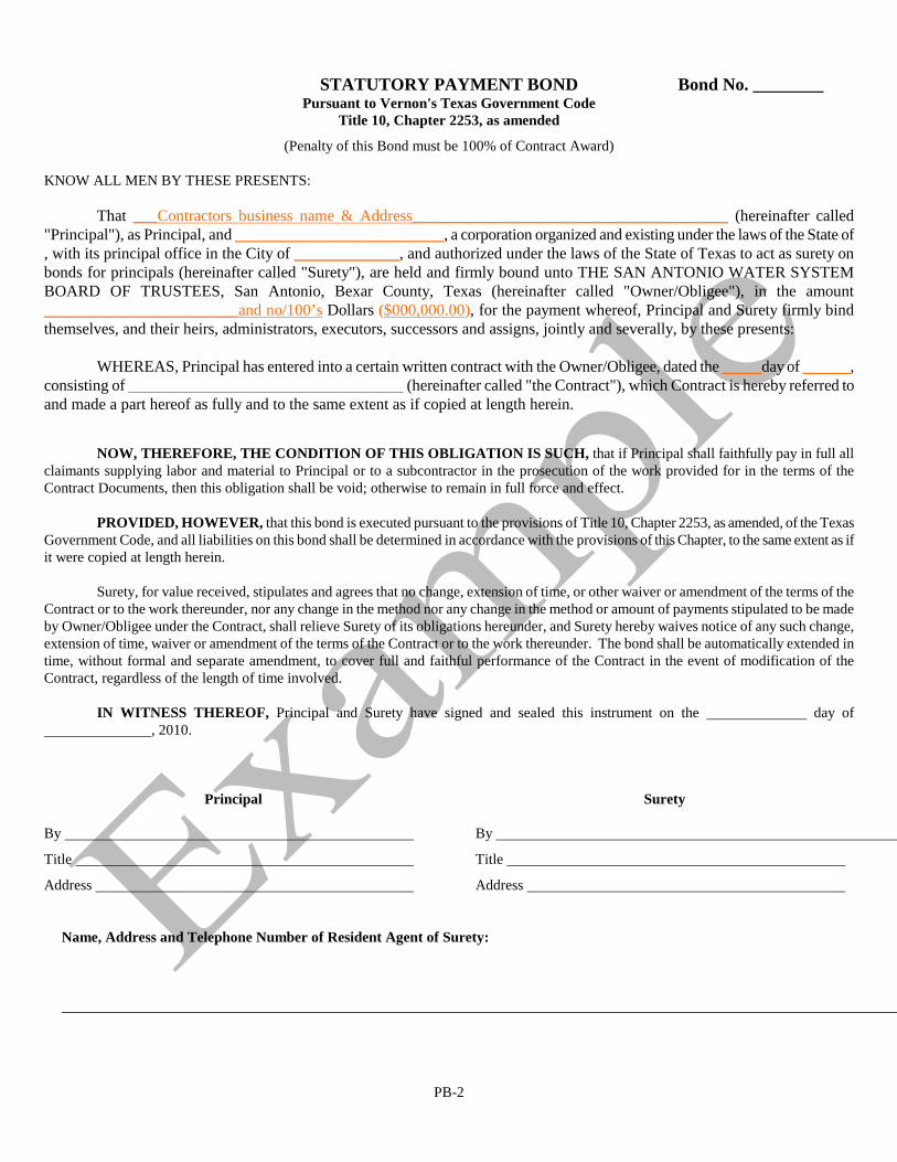
STATUTORY PAYMENT BOND Bond No. ________ Pursuant to Vernon's Texas Government Code Title 10, Chapter 2253, as amended
(Penalty of this Bond must be 100% of Contract Award) KNOW ALL MEN BY THESE PRESENTS:
That ___Contractors business name & Address_______________________________________ (hereinafter called "Principal"), as Principal, and __________________________, a corporation organized and existing under the laws of the State of , with its principal office in the City of _____________, and authorized under the laws of the State of Texas to act as surety on bonds for principals (hereinafter called "Surety"), are held and firmly bound unto THE SAN ANTONIO WATER SYSTEM BOARD OF TRUSTEES, San Antonio, Bexar County, Texas (hereinafter called "Owner/Obligee"), in the amount ________________________and no/100’s Dollars ($000,000.00
), for the payment whereof, Principal and Surety firmly bind themselves, and their heirs, administrators, executors, successors and assigns, jointly and severally, by these presents:
WHEREAS, Principal has entered into a certain written contract with the Owner/Obligee, dated the _____day of ______, consisting of __________________________________
(hereinafter called "the Contract"), which Contract is hereby referred to and made a part hereof as fully and to the same extent as if copied at length herein.
NOW, THEREFORE, THE CONDITION OF THIS OBLIGATION IS SUCH, that if Principal shall faithfully pay in full all claimants supplying labor and material to Principal or to a subcontractor in the prosecution of the work provided for in the terms of the Contract Documents, then this obligation shall be void; otherwise to remain in full force and effect.
PROVIDED, HOWEVER, that this bond is executed pursuant to the provisions of Title 10, Chapter 2253, as amended, of the Texas Government Code, and all liabilities on this bond shall be determined in accordance with the provisions of this Chapter, to the same extent as if it were copied at length herein.
Surety, for value received, stipulates and agrees that no change, extension of time, or other waiver or amendment of the terms of the Contract or to the work thereunder, nor any change in the method nor any change in the method or amount of payments stipulated to be made by Owner/Obligee under the Contract, shall relieve Surety of its obligations hereunder, and Surety hereby waives notice of any such change, extension of time, waiver or amendment of the terms of the Contract or to the work thereunder. The bond shall be automatically extended in time, without formal and separate amendment, to cover full and faithful performance of the Contract in the event of modification of the Contract, regardless of the length of time involved.
IN WITNESS THEREOF, Principal and Surety have signed and sealed this instrument on the day of , 2010. Principal By
Title
Address
Surety By
Title
Address
Name, Address and Telephone Number of Resident Agent of Surety:
PB-2

Rev. 06/10
WA 1
EXHIBIT A
WORKERS' COMPENSATION INSURANCE COVERAGE
(A) Definitions: Certificate of Coverage ("certificate") A copy of a certificate of insurance, acertificate of authority to self-insure issued by the commission, of a coverage agreement(TWCC-81, TWCC-82, TWCC-83, or TWCC-84), showing statutory workers'compensation insurance coverage for the person's or entity's employees providing serviceson a project, for the duration of the project. Duration of the project includes the time fromthe beginning of the work on the project until the contractor's/person's work on the projecthas been completed and accepted by the governmental entity. Persons providing services onthe project ("subcontractor" in §406.096) -includes all persons or entities performing all orpart of the services the contractor has undertaken to perform on the project, regardless ofwhether that person contracted directly with the contractor and regardless of whether thatperson has employees. This includes, without limitation, independent contractors,subcontractors, leasing companies, motor carriers, owner-operators, employees of any suchentity, or employees of any entity which furnishes persons to provide services on the project. "Services" include, without limitation, providing, hauling, or delivering equipment ormaterials, or providing labor, transportation, or other services related to a project.
(B) The contractor shall provide coverage, based on proper reporting of classification codes andpayroll amounts and filing of any coverage agreements, which meets the statutoryrequirements of Texas Labor Code, §401.011(44) for all employees of the contractorproviding services on the project, for the duration of the project.
(C) The Contractor must provide a certificate of coverage to the governmental entity prior tobeing awarded the contract.
(D) If the coverage period shown on the contractor's current certificate of coverage ends duringthe duration of the project, the contractor must, prior to the end of the coverage period, file anew certificate of coverage with the governmental entity showing that coverage has beenextended.
(E) The contractor shall obtain from each person providing services on a project, and provide tothe governmental entity:
(i) a certificate of coverage, prior to that person beginning work on the project, so thegovernmental entity will have on file certificates of coverage showing coverage forall persons providing service on the project; and
(ii) no later than seven days after receipt by the contractor, a new certificate of coverageshowing extension of coverage, if the coverage period shown on the currentcertificate of coverage ends during the duration of the project.

Rev. 06/10
WA 2
(F) The contractor shall retain all required certificates of coverage for the duration of the projectand for three (3) years thereafter.
(G) The contractor shall notify the governmental entity in writing by certified mail or personaldelivery, within ten (10) days after the contractor knew or should have known, of any changethat materially affects the provision of coverage of any person providing services on theproject.
(H) The contractor shall post on each project site a notice, in the text, form and mannerprescribed by the Texas Workers' Compensation Commission, informing all personsproviding services on the project that they are required to be covered, and stating how aperson may verify coverage and report lack of coverage.
(I) The contractor shall contractually require each person with whom it contracts to provideservices on a project, to:
(i) provide coverage based on proper reporting of classification codes and payrollamounts and filing of any coverage agreements, which meets the statutoryrequirements of Texas Labor Code, §401.011(44) for all of its employees providingservices on the project, for the duration of the project;
(ii) provide to the contractor, prior to that person beginning work on the project, acertificate of coverage showing that coverage is being provided for all employees ofthe person providing services on the project, for the duration of the project;
(iii) provide the contractor, prior to the end of the coverage period, a new certificate ofcoverage showing extension of coverage, if the coverage period shown on the currentcertificate of coverage ends during the duration of the project;
(iv) obtain from each other person with whom it contracts, and provide to the contractor:
(I) a certificate of coverage showing extension of coverage, prior to the otherperson beginning work on the project; and
(II) a new certificate of coverage showing extension of coverage, prior to the endof coverage period, if the coverage period shown on the current certificate ofcoverage ends during the duration of the project;
(v) retain all required certificates of coverage on file for the duration of the project andfor three (3) years thereafter;
(vi) notify the governmental entity in writing by certified mail or personal delivery withinten (10) days after the person knew or should have known, of any change that

Rev. 06/10
WA 3
materially affects the provision of coverage of any person providing services on theproject; and
(vii) contractually require each person with whom it contracts, to perform as required byclauses (i) - (vii) of this subparagraph, with the certificates of coverage to beprovided to the person to whom they are providing services.
(J) The contractor's failure to comply with any of these provisions is a breach of contract by thecontractor which entitles the governmental entity to declare the contract void if thecontractor does not remedy the breach within ten (10) days after receipt of notice of breachfrom the governmental entity.

This page intentionally left blank.

EXHIBIT B
ADMINISTRATIVE AND OPERATIONAL PROCEDURES FORCONTRACTOR BID SUSPENSION HEARINGS AND APPEALS
I. SCOPE
These Administrative and Operational Procedures for Contractor Bid SuspensionHearings and Appeals apply to all contractors awarded contracts with SAWS.
The term “contractor” as used in these Procedures means a construction contractor,subcontractor, vendor, supplier, materialman or any other person or entity supplyinglabor or material to SAWS on a contract basis.
"SAWS Management Officials" means SAWS personnel who are at the Managerlevel or above and who are involved in the supervision, review or acceptance ofservices, work or materials provided by contractors under contract with SAWS.
II. GENERAL PROCEDURES
A. If a SAWS Management Official determines that a particular contractor’sresponsiveness, capabilities or performance under one or more SAWScontracts is unsatisfactory, the SAWS Management Official may file acomplaint with the Chief Operating Officer recommending that the particularcontractor be suspended from consideration for award of contracts withSAWS. A complaint may not be filed unless:
1) SAWS has sent the contractor at least three letters advising that thecontractor is in non-compliance with a contract with SAWS, and theletters each include a warning that further defaults or breaches may lead toa suspension; or
2) the contractor has had a previous contract with SAWS terminated forcontractor default; or
3) either the City of San Antonio or the State of Texas has suspended thecontractor.
B. A SAWS Management Official filing a complaint will provide the ContractingCommittee with any information he or she may have relating to the Reasonsfor Contractor Suspension as described in Section 4.9, Contractor BidSuspension Policy of the General Conditions.
Rev. 06/10 SP 1

C. SAWS will maintain the materials relating to any and all complaints filedagainst a particular contractor in a “complaint file” pertaining to thecontractor.
D. A contractor may be suspended if the contractor is determined by theContracting Committee to be not sufficiently responsible to warrantconsideration for award of contracts with SAWS.
III. RIGHTS AT HEARING
A hearing on a complaint will be held before a Contracting Committee which willreview the evidence presented at the hearing and make a determination as to whetherthe contractor should be suspended. The Committee will select a chair to preside atthe hearing. At the hearing, SAWS and the contractor will each have the followingrights and opportunities:
A. to be heard before an impartial committee;
B. to be represented by an attorney or a representative of choice;
C. to hear the witnesses and other evidence presented by the opposing party;
D. to cross-examine adverse witnesses;
E. to testify on one’s own behalf;
F. to present witnesses and other evidence on one's own behalf;
G. to have a record of the hearing made, by transcript, tape, or otherwise;
H. to have all testimony presented under oath.
IV. COMMITTEE PROCESS
A. The President/Chief Executive Officer of SAWS shall appoint a standingContracting Committee comprising of SAWS staff. At least one Committeemember will be a Vice President of SAWS and all other Committee memberswill be Managers or higher. If a standing Contracting Committee member hasbeen involved in the day-to-day administration or supervision of a contractwith a contractor being reviewed by the Committee, such Committee memberwill not serve on the Committee with regard to a complaint or appeal affectingthat contractor. The President/CEO may either appoint a substitute or theCommittee may proceed with fewer members, but in no event will there beless than three members available at any Committee meeting to hear evidenceor take action on a complaint or appeal. The members of the Committee
Rev. 06/10 SP 2

hearing the complaint will be SAWS Management Officials not directlyinvolved with the contractor being considered for bid suspension.
B. When a SAWS Management Official submits a complaint to the ChiefOperating Officer, the Chief Operating Officer will review the complaint todetermine whether to convene the Contracting Committee to hear and act onthe complaint. The Committee will be convened on a case-by-case basis.
C. The Contracting Committee will review evidence, obtain testimony fromwitnesses, deliberate and vote on the matters brought before the Committee.The Committee will consider (i) all evidence in the complaint file pertainingto the contractor and any previously filed complaints and (ii) any otherrelevant evidence pertaining to the contractor, including evidence presentedby SAWS Management Officials familiar with the contractor's performance.
D. After considering all relevant evidence, the Contracting Committee willeither:
1) take no action other than sending a written warning notice by certifiedmail, return receipt requested, to the contractor (i) indicating thatpursuant to these procedures, the Committee has received a complaintregarding the contractor, (ii) indicating that after reviewing thecomplaint and related evidence, the Committee has decided, at thistime, to take no action regarding the contractor, and (iii) including anyother information that the Committee, in its discretion, deemsappropriate; or
2) pursuant to these procedures, suspend the contractor fromconsideration for awards of contracts with SAWS.
E. If the Contracting Committee decides to suspend the contractor, theCommittee will send written notice as described in General Conditions,Section 4.9, Contractor Bid Suspension Policy, indicating the following:
1) that, pursuant to these procedures, the contractor has been suspendedfrom consideration for award of contracts with SAWS;
2) in general terms, the reasons for the suspension;
3) that the suspension commences upon issuance of the notice ofsuspension;
4) the length of time and other relevant terms of the suspension asdelineated in these procedures;
Rev. 06/10 SP 3
5) that bids or proposals will not be accepted or solicited from thecontractor, and if they are received, they will not be opened andconsidered for award during the suspension period; and
6) the Contractor’s right to appeal the suspension pursuant to theseprocedures.
V. PROCEDURE AT HEARING
The procedure described below will be followed in a general sense. The ContractingCommittee may vary these procedures when necessary because of circumstances.
A. Copies of Exhibits
Whenever possible, the party wishing to introduce exhibits should makesufficient copies ahead of time. This will prevent interruptions and delays ofthe proceedings. Generally, in addition to those to be used by the party andthe witness, copies will be made available to each of the Committee members,one for the official record and one for the representative of the other party.
B. Order of Presentation
After the beginning formalities, each party will be allowed an opportunity tomake a brief introductory statement.
Initially, SAWS will present the evidence it believes warrants the suspension.As each witness is called, the contractor or the contractor'sattorney/representative will have the right to cross-examine the witness afterthe witness has testified and before the next witness is called. The contractoror the contractor's attorney/representative may object to testimony andexhibits.
After the presentation of SAWS’ evidence, the contractor may presentevidence, including his or her own testimony and that of others. As eachwitness is called, SAWS will have the right to cross-examine each witnessafter the witness has testified and before the next witness is called. A SAWSManagement Official may object to testimony and exhibits.
After the contractor has presented his/her case, SAWS may recall witnessesand present additional witnesses or evidence, again subject to cross-examination and objections. After this, the contractor may recall witnessesand present additional witnesses or evidence, also subject to cross-examination and objections.
Each party may be allowed additional time to present further rebuttalevidence.
Rev. 06/10 SP 4
After the presentation of the evidence, and before the close of the hearing,each party will have the opportunity to give a brief closing argument orsummary of his/her position. The Committee may limit the time available toeach of the parties depending on the amount of evidence, issues, or othercircumstances the Committee deems appropriate.
The Committee will ensure the orderly and efficient presentation of theevidence.
The Committee will rule on any objection to testimony or other evidence.
The Committee will have the right to prevent any threatening or abusivelanguage or conduct and to exclude witnesses who engage in conduct that isdisruptive of the proceedings.
Stipulations (i.e., agreements between all affected parties) which expedite theproceedings are highly favored. Therefore, both SAWS and the contractor areencouraged to reach agreements regarding the admissibility of documents andthe proposed testimony of witnesses. Where both SAWS and the contractor(or his/her attorney/representative) have agreed in writing or “on the record,”affidavits of absent witnesses may be introduced.
All testimony will be under oath. The Committee chair or his/her designeewill administer the oaths.
In its discretion, the Committee may limit or exclude testimony that issuperfluous or irrelevant.
The Committee will utilize its discretion regarding the amount of timeallowed for each proceeding and will have the authority to make decisions thatwill expedite the proceedings.
In the Committee's discretion, Committee members may ask questions of anywitness or party when they believe clarification or further information isneeded.
Unless testifying as an expert, no witness may testify unless he or she haspersonal knowledge regarding the issues, events, and matters relevant to thehearing.
The Committee may exclude or limit witnesses who do not have personalknowledge regarding the issues, events, and matters relevant to the hearing.
The Committee may take other appropriate action when the contractor fails toattend the hearing.
Rev. 06/10 SP 5

VI. POSTPONEMENTS
Postponements are not favored. However, where emergency circumstances arebeyond the control of the contractor, the Contracting Committee will considerpostponing the hearing. There will be no guarantee that a second postponement willbe granted.
VII. SUSPENSIONS
A. If the contractor has not been previously suspended pursuant to theseprocedures, the term of the suspension will be for one year from the date ofissuance of the notice of suspension.
B. If the contractor has been previously suspended pursuant to these procedures,the term of the suspension will be for two years from the date of issuance ofthe notice of suspension.
C. After the suspension period is over, the contractor may resume submittingbids for SAWS contracts, provided, however, that initially SAWS will awardno more than one contract to the suspended contractor. Only after thesatisfactory completion of such contract will SAWS resume considering theaward of multiple contracts to the contractor. The period of time after thesuspension period is over but before SAWS will consider awarding multiplecontracts to the contractor is referred to as the “post-suspension period.” Thepurpose of the post-suspension period is to provide SAWS an opportunity toconfirm that the contractor has demonstrated a satisfactory level ofresponsibility to warrant the award of further SAWS contracts.
D. Unless the Contracting Committee, in its sole discretion, decides otherwise,during the suspension period and the post-suspension period the contractormay not provide SAWS with labor or materials as a contractor or asubcontractor through another contractor. (This provision does not apply tothe single contract that may be awarded to the contractor by SAWS during thepost-suspension period or to any contracts or subcontracts in effect prior to theissuance of the notice of suspension.)
E. If another contractor (“other contractor”) hires a suspended contractor toprovide labor or material on a SAWS project while the contractor issuspended from SAWS work, SAWS may notify the other contractor that heor she has 30 days in which to remove the suspended contractor from theSAWS project. If the other contractor does not remove the suspendedcontractor from the SAWS project within 30 days, SAWS may either (i) rejectthe portion of the other contractor’s work performed by the suspendedcontractor because it was performed by a suspended contractor, or (ii)immediately terminate the other contractor’s contract for the project.
Rev. 06/10 SP 6
Continued use of a suspended contractor after the 30 day notice and cureperiod will be an event of default under any contract the other contractor haswith SAWS under which the suspended contractor provides labor and/ormaterials.
F. Notwithstanding the foregoing, a suspended contractor may provideequipment to SAWS as a subcontractor through another contractor, unless theContracting Committee, in its sole discretion, decides otherwise. In addition,any contractor may hire employees of a suspended contractor as its employeesand use them on a SAWS project.
G. Unless the Contracting Committee, in its sole discretion, decides otherwise, ifone or more of the former principal officers or owners of a suspendedcontractor forms a new business entity or joins a different business entity, or ifthe suspended contractor is reconstituted as or made a part of a new ordifferent business entity by any means, the terms of the suspension will applyto the new or different business entity as if the new or different business entitywere one and the same as the suspended contractor.
H. All bids for contracts submitted to SAWS by the contractor prior to theissuance of the notice of suspension and all contracts existing between SAWSand the contractor prior to the issuance of the notice of suspension will remainvalid and effective on their own accord regardless of the suspension.Notwithstanding the suspension, both SAWS and the contractor will remainobligated to perform all duties owed one another pursuant to any contracts orsubcontracts in effect prior to the issuance of the notice of suspension.
VIII. APPEALS
A. A suspended contractor may request an appeal hearing regarding thesuspension, provided such request is received in writing by the ContractingCommittee within 10 days after the contractor has received notice of thesuspension. If no written request for an appeal hearing is received by theCommittee within such 10 day period, then the decision to suspend will befinal and conclusive.
B. If an appeal hearing is requested, the Contracting Committee will schedule theappeal hearing to be held within 10 days after it receives the written request.The Committee will send the contractor written notice by certified mail, returnreceipt requested, of the time and place of the hearing.
C. Both SAWS and the contractor will be allowed to request only onepostponement of the appeal hearing. Any such request must be in writing andreceived by the other party at least five days before the originally scheduleddate of the appeal hearing. In the event of a postponement, the ContractingCommittee will reschedule the appeal hearing to be held within 10 days of the
Rev. 06/10 SP 7
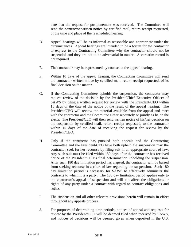
date that the request for postponement was received. The Committee willsend the contractor written notice by certified mail, return receipt requested,of the time and place of the rescheduled hearing.
D. Appeal hearings will be as informal as reasonable and appropriate under thecircumstances. Appeal hearings are intended to be a forum for the contractorto express to the Contracting Committee why the contractor should not besuspended and they are not to be adversarial in nature. A verbatim record isnot required.
E. The contractor may be represented by counsel at the appeal hearing.
F. Within 10 days of the appeal hearing, the Contracting Committee will sendthe contractor written notice by certified mail, return receipt requested, of itsfinal decision on the matter.
G. If the Contracting Committee upholds the suspension, the contractor mayrequest review of the decision by the President/Chief Executive Officer ofSAWS by filing a written request for review with the President/CEO within10 days of the date of the notice of the result of the appeal hearing. ThePresident/CEO will review the material available from the appeal and meetwith the contractor and the Committee either separately or jointly as he or sheelects. The President/CEO will then send written notice of his/her decision onthe suspension by certified mail, return receipt requested, to the contractorwithin 15 days of the date of receiving the request for review by thePresident/CEO.
H. Only if the contractor has pursued both appeals and the ContractingCommittee and the President/CEO have both upheld the suspension may thecontractor seek further recourse by filing suit in an appropriate court of law.Any such suit must be filed within 180 days after the contractor has receivednotice of the President/CEO’s final determination upholding the suspension.After such 180 day limitation period has elapsed, the contractor will be barredfrom seeking recourse in a court of law regarding the suspension. Such 180day limitation period is necessary for SAWS to effectively administer thecontracts to which it is a party. The 180 day limitation period applies only tothe contractor’s appeal of suspension and will not affect the obligations orrights of any party under a contract with regard to contract obligations andrights.
I. The suspension and all other relevant provisions herein will remain in effectthroughout any appeals process.
J. For purposes of determining time periods, notices of appeal and requests forreview by the President/CEO will be deemed filed when received by SAWS,and notices of decisions will be deemed given when deposited in the U.S.
Rev. 06/10 SP 8

Mail, certified mail, return receipt requested, addressed to the contractor at theaddress given on the notice of appeal or the contractor’s last contract withSAWS.
Rev. 06/10 SP 9

Exhibit “C” SECURITY PROCEDURES
If work will be conducted on SAWS property, on a SAWS customer’s property, involve any SAWS networks or any SAWS facility the Contractor shall ensure a Prime Contractor Data Form (PCDF) and a Background Screening Letter (provided by SAWS Security) is properly completed for all employees performing work under this Agreement and is on file with SAWS Security prior to work commencement. Any person found to have an unacceptable background check will not be allowed to perform work under this Agreement ( A waiver may be given by SAWS Security for an unacceptable finding but must be signed off by the Director of SAWS Security ). Sub-Contractors performing work must be listed on the PCDF and the Background Screening Letter. Contractor shall be responsible for the accuracy of information on the PCDF and the Background Screening Letter, and for obtaining any and all required items (badges and parking tags) necessary to fulfilling the work under this Agreement. The PCDF and Background Screening Letter must be sent electronically to [email protected]. Contractor shall advise the SAWS Project Manager/Inspector of any employee terminations or changes to personnel performing work under this Agreement and the Contractor shall immediately turn in any and all badges and/or parking tags of employees who are terminated or no longer performing work under this Agreement. If there are any changes in the information contained in the PCDF or the Background Screening Letters, Contractor shall immediately notify the SAWS Project Manager/Inspector and provide updated PCDF and Background Screening Letters, with copies to [email protected]. Contractor, its employees, and agents shall obtain a SAWS photo identification badge (Contractor's Badge) and parking tag, prior to any work on SAWS property, which shall be used only for purposes necessary to perform the work under this Agreement. SAWS Badge Office hours are Monday, Wednesday and Friday 8:00am to 12:00pm excluding SAWS holidays (hours are subject to change). Security staff can be contacted at (210) 233-3177 or (210) 233-3338. A replacement fee may be charged for lost or damaged badges or parking tags. As a condition of final payment, Contractor shall return all badges and parking tags to the Security Office. In the event Contractor fails to return all security badges and parking tags, in addition to any other rights or remedies to which SAWS may be entitled at law or in equity, SAWS may withhold from payment to the Contractor the sum of $500.00 dollars per badge or parking tag as liquidated damages. Contractor agrees that the actual amount of damages for failure to return the badges and/or parking tags are difficult to determine, and the liquidated damages herein are not a penalty, but are a reasonable estimate of the costs and expenses that may be incurred by SAWS for failure to return the badges or parking tags. SAWS facilities require a SAWS employee to physically escort Contractor at all times. SAWS may, in its sole discretion, waive the escort requirements if the PCDF and a “clean” Background Screening Letter, signed by an authorized representative of Contractor are approved by SAWS Security. Sub-Contractors must always be under escort of the Contractor while performing work on any SAWS property. Sub-Contractors must display either a company photo badge, with name, or a valid driver’s license at all times while working on any SAWS property. Contractor is solely responsible for the actions of its employees, agents, sub contractors and Contractors. Contractor MUST be prepared for additional security requirements at its expense if violations of SAWS Security procedures are noted. Some examples of additional requirements include hiring of SAWS approved security guards, temporary fencing, mobile Closed Circuit Television Monitoring trailer(s), or extra lighting. Notwithstanding anything herein to the contrary, any provisions in these Security Procedures that may appear to give SAWS the right to direct Contractor as to details of doing any work under this Agreement or to exercise a measure of control over any security measures or such work shall be deemed to mean that Contractor shall follow the desires of SAWS in the results of the work or security measures only. Advance coordination by Contractor with SAWS Security for these security requirements is necessary to ensure no delays with timely performance of the work. In the event Contractor fails to comply with SAWS Security requirements, SAWS may, with no penalty or claim against SAWS:
• Issue a Work Stoppage Order until the security violation (s) are remedied • Ask any unidentified or improperly identified person or equipment to leave SAWS site immediately and not
return until items are remedied. Rev. 07/27/12 Page 1of 1


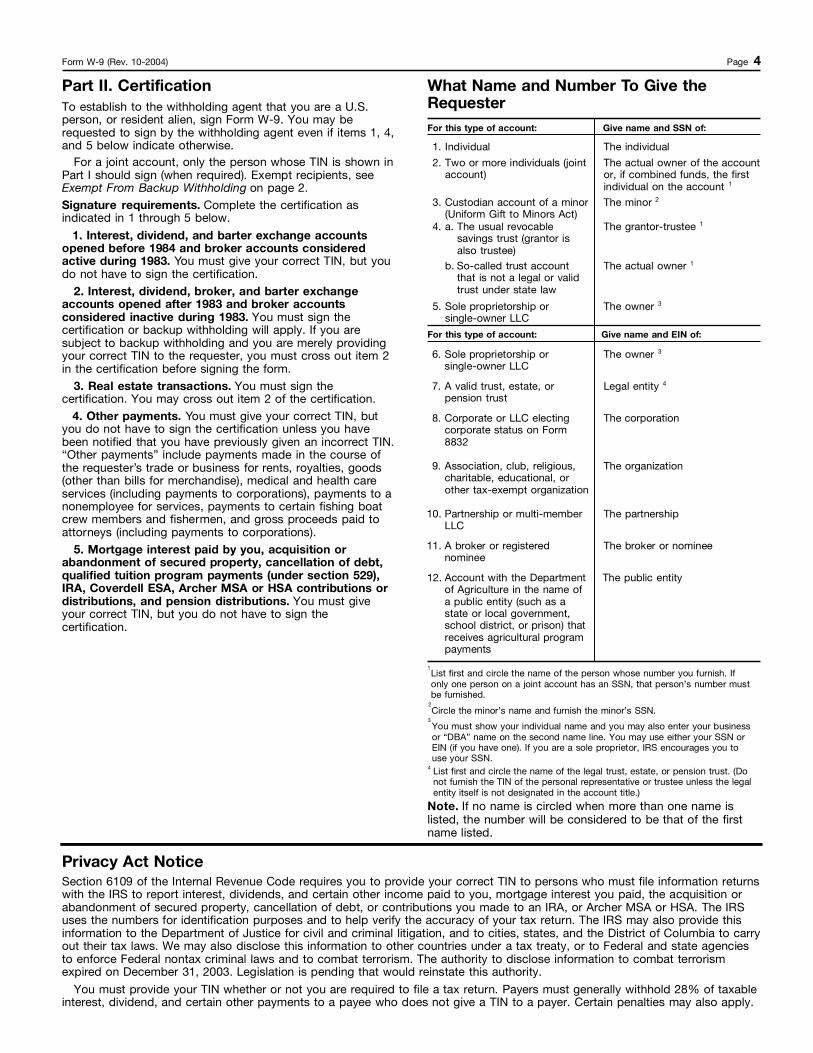

Instructions for Completing the ACORDCertificate of Liability Insurance
(Form – ACORD 25 [2001/08] updated)
1. DATE (MM/DD/YYYY) – this is the date the Certificate is generated;
2. PRODUCER – insert the complete name and address of the insurance agency or broker issuingthis Certificate; Contact person’s office phone, Fax number and email address.
3. INSURED – enter the complete legal name and address of the Consulting Firm, the Contractor’sCompany or the Supplier’s Company (to include any dba used);
4. INSURERS AFFORDING COVERAGE
a. INSURER A through E – enter the insurance carrier’s complete Operating Company name; or
b. NAIC # - enter National Association of Insurance Commissioners (5 – digit) insurance carrier IDnumber.
NOTE:
If the name of the Insurer used cannot be located in the A.M. Best Directory, then the NAIC #will be required.
5. COVERAGES
a. INSURER Letter (INSR/LTR) column - place the corresponding letter of the insurance carrieraffording coverage by each respective type of insurance coverage;
b. ADDITIONAL INSURED (ADD’L INSURD) column
This column is provided to indicate by a check mark or an “X” as to whether a line of insurancecoverage listed on the Certificate is endorsed with the Additional Insured endorsement (exceptfor Workers’ Compensation/Employer’s Liability).
The use of this column alone does not constitute compliance with SAWS InsuranceSpecifications.
SAWS requires the following specific endorsement wording for the Additional Insuredendorsement, to be inserted into the DESCRIPTION OF OPERATIONS section of theCertificate:
Date: September 14, 2010 Page 1 of 7

Instructions for Completing the ACORDCertificate of Liability Insurance
(Form – ACORD 25 [2001/08] updated)
Additional Insured – “The Automobile Liability, Commercial General Liability andUmbrella Liability policies are endorsed naming the San Antonio Water System and the Cityof San Antonio as an Additional Insured.”
c. TYPE OF INSURANCE:
1) GENERAL LIABILITY:
a) COMMERCIAL GENERAL LIABILITY – place an “X” in the space provided;
b) OCCUR (Occurrence based form) - place an “X” in the space provided;
c) GEN’L AGGREGATE LIMIT APPLIES PER:
For Construction Contracts - place an “X” in the box right in front of the wordPROJECT; or
For all Other Contracts - an “X” in the box right in front of either the word POLICYor LOCATION is acceptable.
d) Enter complete POLICY NUMBER, POLICY EFFECTIVE DATE(MM/DD/YYYY), and POLICY EXPIRATION DATE (MM/DD/YYYY);
e) The minimum policy LIMITS for the Commercial General Liability coverage are asfollows:
$ 1,000,000.00 Occurrence Limit 2,000,000.00 General Aggregate 1,000,000.00 Products/Completed Operations Aggregate (See NOTE below)
1,000,000.00 Personal and Advertising Injury
NOTE:
The above limits for Products/Completed Operations Aggregate for all ConstructionContracts is $2 million.
2) AUTOMOBILE LIABILITY:
a) Place an “X” in the box in front of each appropriate auto category for which coverageapplies.
b) Enter complete POLICY NUMBER, POLICY EFFECTIVE DATE(MM/DD/YYYY), and POLICY EXPIRATION DATE (MM/DD/YYYY).
Date: September 14, 2010 Page 2 of 7

Instructions for Completing the ACORDCertificate of Liability Insurance
(Form – ACORD 25 [2001/08] updated)
c) The typical minimum limits of liability for bodily injury and property damage combinedfor this line of insurance coverage shall be not less than $1,000,000.00 each accident.
NOTE:
If the Contractor’s Pollution Liability policy is required and the Contractor’s PollutionLiability policy is not endorsed to provide transportation coverage beyond theboundaries of the job site the Commercial/Business Automobile Liability policy musthave the CA9948 endorsement (Pollution Liability – Broadened Coverage forCovered Autos – Business Auto, Motor Carrier and Truckers Coverage forms) - thefollowing statement noting this endorsement shall be placed either in the blank area justbelow the NON-OWNED AUTOS wording on the Certificate or in the DESCRIPTIONOF OPERATIONS section of the Certificate:
“Contractor’s Commercial/Business Automobile Liability insurance coverage isendorsed with the CA9948 endorsement to provide transportation coverage beyondthe boundaries of the job site.”
Policy must also be endorsed with MCS90 endorsement when hazardous material(s) arebeing transported.
3) GARAGE LIABILITY - not applicable.
4) EXCESS/UMBRELLA LIABILITY (where applicable):
a) SAWS prefers having an “X” in the box right in front of the word OCCUR;
b) In the blank space provided underneath the OCCUR and CLAIMS MADE boxes or atanother location more convenient on the Certificate, insert the name of the coverage formunder which this Liability Policy is written; either:
Umbrella form; or
Other than Umbrella form.
c) Enter complete POLICY NUMBER, POLICY EFFECTIVE DATE(MM/DD/YYYY), and POLICY EXPIRATION DATE (MM/DD/YYYY).
d) The minimum limits* of liability for this line of insurance coverage shall be:
$ 2,000,000.00 Occurrence Limit
Date: September 14, 2010 Page 3 of 7

Instructions for Completing the ACORDCertificate of Liability Insurance
(Form – ACORD 25 [2001/08] updated)
2,000,000.00 General Aggregate
*The above limits may vary from $5 million to $50 million depending on the degree ofand potential for greater liability exposure to SAWS. Check the General Conditions –Special Conditions section of the Bid document for the increased coverage limits.
5) WORKERS’ COMPENSATION AND EMPLOYER’S LIABILITY:
a) Answer the Question: ANY PROPRIETOR/PARTNER/EXECUTIVE OFFICER/MEMBER EXCLUDED? If yes, describe under SPECIAL PROVISIONS below.
b) Enter complete POLICY NUMBER, POLICY EFFECTIVE DATE(MM/DD/YYYY), and POLICY EXPIRATION DATE (MM/DD/YYYY).
c) WORKERS’ COMPENSATION (“WC”):
SAWS requires having an “X” entered in the box right in front of the words WCSTATUTORY LIMITS.
d) EMPLOYERS’ LIABILITY (“E.L.”):
The minimum policy limits of liability shall not be less than:
$ 1,000,000.00 E.L. each Accident 1,000,000.00 E.L. Disease - Each Employee 1,000,000.00 E.L. Disease - Policy Limit
6) OTHER:
a) This empty slot of spaces is typically used for such lines of coverage asPROFESSIONAL (Engineer’s & Architect’s E&O) LIABILITY, CONTRACTOR’SPOLLUTION LIABILITY, COMMERCIAL CRIME and/or BUILDER’S RISK lines ofinsurance coverage.
b) Enter complete POLICY NUMBER, POLICY EFFECTIVE DATE(MM/DD/YYYY), and POLICY EXPIRATION DATE (MM/DD/YYYY).
c) The minimum limits (the per occurrence/claims-reported limit as well as the policyaggregate limit) for whichever TYPE OF INSURANCE coverage you are declaring inthis OTHER space must match with or exceed limits stated in the InsuranceSpecifications/Requirements contained in the respective Construction Bid, RFP or RFQdocument.
Date: September 14, 2010 Page 4 of 7

Instructions for Completing the ACORDCertificate of Liability Insurance
(Form – ACORD 25 [2001/08] updated)
NOTE:
1. If the line of insurance coverage is either for Professional Liability or Contractor’sPollution Liability, identify in the DESCRIPTION OF OPERATIONS section ofthe Certificate the coverage form under which the respective line of coverage iswritten – either:
a. Claims-made form; or
b. Occurrence basis.
2. In instances where the coverage form used is Claims-made include the “Retro-Active date” according to the following:
a. For all contracts requiring Professional Liability and/or Contractor’s PollutionLiability coverage, the “Retro-Active date” shall be the Project start date orearlier and must be identified in the DESCRIPTION OF OPERATIONS sectionof the Certificate.
b. That date must be maintained (carried forward) as the “Retro-Active date”throughout the life of the Project/Contract to include the two-year warranty period(if required) following the close out of the Project/Contract.
3. If the Occurrence based coverage form is declared, no further information is required;and
4. If the Contractor’s Pollution Liability insurance coverage is required, the policy shallbe endorsed to provide transportation coverage beyond the boundaries of the job site– the following statement noting this endorsement shall be placed in theDESCRIPTION OF OPERATIONS section of the Certificate;
“Contractor’s Pollution Liability insurance coverage is endorsed to providetransportation coverage beyond the boundaries of the job site.”
If the Contractor’s Pollution Liability policy is not endorsed to providetransportation coverage beyond the boundaries of the job site then theCommercial/Business Automobile Liability policy must have the CA9948endorsement (“Pollution Liability – Broadened Coverage for Covered Autos –Business Auto, Motor Carrier and Truckers Coverage” forms) - the followingstatement noting this endorsement shall be placed either in the blank area just belowthe NON-OWNED AUTOS wording on the Certificate or in the DESCRIPTIONOF OPERATIONS section of the Certificate:
Date: September 14, 2010 Page 5 of 7
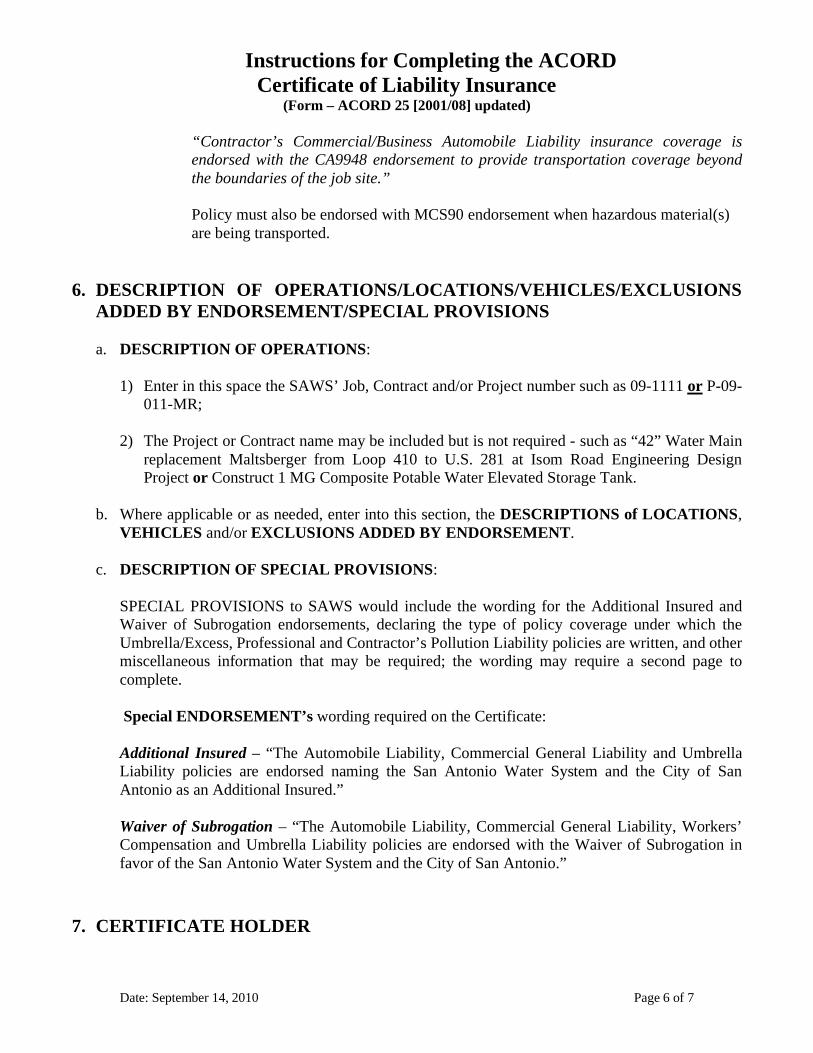
Instructions for Completing the ACORDCertificate of Liability Insurance
(Form – ACORD 25 [2001/08] updated)
“Contractor’s Commercial/Business Automobile Liability insurance coverage isendorsed with the CA9948 endorsement to provide transportation coverage beyondthe boundaries of the job site.”
Policy must also be endorsed with MCS90 endorsement when hazardous material(s)are being transported.
6. DESCRIPTION OF OPERATIONS/LOCATIONS/VEHICLES/EXCLUSIONSADDED BY ENDORSEMENT/SPECIAL PROVISIONS
a. DESCRIPTION OF OPERATIONS:
1) Enter in this space the SAWS’ Job, Contract and/or Project number such as 09-1111 or P-09-011-MR;
2) The Project or Contract name may be included but is not required - such as “42” Water Mainreplacement Maltsberger from Loop 410 to U.S. 281 at Isom Road Engineering DesignProject or Construct 1 MG Composite Potable Water Elevated Storage Tank.
b. Where applicable or as needed, enter into this section, the DESCRIPTIONS of LOCATIONS,VEHICLES and/or EXCLUSIONS ADDED BY ENDORSEMENT.
c. DESCRIPTION OF SPECIAL PROVISIONS:
SPECIAL PROVISIONS to SAWS would include the wording for the Additional Insured andWaiver of Subrogation endorsements, declaring the type of policy coverage under which theUmbrella/Excess, Professional and Contractor’s Pollution Liability policies are written, and othermiscellaneous information that may be required; the wording may require a second page tocomplete.
Special ENDORSEMENT’s wording required on the Certificate:
Additional Insured – “The Automobile Liability, Commercial General Liability and UmbrellaLiability policies are endorsed naming the San Antonio Water System and the City of SanAntonio as an Additional Insured.”
Waiver of Subrogation – “The Automobile Liability, Commercial General Liability, Workers’Compensation and Umbrella Liability policies are endorsed with the Waiver of Subrogation infavor of the San Antonio Water System and the City of San Antonio.”
7. CERTIFICATE HOLDER
Date: September 14, 2010 Page 6 of 7

Instructions for Completing the ACORDCertificate of Liability Insurance
(Form – ACORD 25 [2001/08] updated)
Date: September 14, 2010 Page 7 of 7
SAWS shall be shown as the Certificate Holder in the Certificate Holder section located in thebottom half of the standard ACORD Certificate forms as follows:
San Antonio Water Systemc/o Ebix BPOPO Box 257Ref. # 107- (SAWS Contract/Bid/Project #)Portland, MI 48875-0257
8. CANCELLATION
Each line of insurance coverage that is shown on this Certificate shall be so written so as to provideSAWS and the City thirty (30) calendar days advance written notice directly of any suspension,cancellation or non-renewal or material change in coverage, and not less than ten (10) calendar daysadvance written notice for nonpayment of premium.
9. AUTHORIZED REPRESENTATIVE
The original certificate(s) or form must include at least one of the below acceptablenames/signatures:
a. Agency’s Authorized person’s (wet or stamped) signature;b. Agent's (wet or stamped) signature; orc. Agent's typed in name.

CERTIFICATE OF LIABILITY INSURANCE DATE (MM/DD/YYYY)
PRODUCER THIS CERTIFICATE IS ISSUED AS A MATTER OF INFORMATION ONLYAND CONFERS NO RIGHTS UPON THE CERTIFICATE HOLDER. THISCERTIFICATE DOES NOT AMEND, EXTEND OR ALTER THECOVERAGE AFFORDED BY THE POLICIES BELOW.
INSURERS AFFORDING COVERAGE NAIC #INSURED
COVERAGES
TYPE OF INSURANCE POLICY NUMBER POLICY EFFECTIVEDATE (MM/DD/YY)
POLICY EXPIRATIONDATE (MM/DD/YY) LIMITS
GENERAL LIABILITY
AUTOMOBILE LIABILITY
GARAGE LIABILITY
EXCESS/UMBRELLA LIABILITY
WORKERS COMPENSATION ANDEMPLOYERS’ LIABILITY
OTHER
DESCRIPTION OF OPERATIONS / LOCATIONS / VEHICLES / EXCLUSIONS ADDED BY ENDORSEMENT / SPECIAL PROVISIONS
CERTIFICATE HOLDER CANCELLATIONSHOULD ANY OF THE ABOVE DESCRIBED POLICIES BE CANCELLED BEFORE THEEXPIRATION DATE THEREOF, THE INSURER AFFORDING COVERAGE WILL ENDEAVOR TOMAIL DAYS WRITTEN NOTICE TO THE CERTIFICATE HOLDER NAMED TO THE LEFT,BUT FAILURE TO DO SO SHALL IMPOSE NO OBLIGATION OR LIABILITY OF ANY KIND UPONTHE INSURER, ITS AGENTS OR REPRESENTATIVES.
AUTHORIZED REPRESENTATIVE
ACORD 25 (2001/08) © ACORD CORPORATION 1988

IMPORTANT
DISCLAIMER
ACORD 25 (2001/08)

Instructions for Completing the ACORDCertificate of Liability Insurance
(Form – ACORD 25 [Versions: 2009/09 & 2010/05])
1. DATE (MM/DD/YYYY) – this is the date the Certificate is generated;
2. PRODUCER – insert the complete name and address of the insurance agency or broker issuingthis Certificate; in the adjacent cell (located just to the right of the PRODUCER cell) includeCONTACT PERSON’s name, office phone, Fax number(s) and e-mail address.
3. INSURED – enter the complete legal name and address of the Consulting Firm, the Contractor’sCompany or the Supplier’s Company (to include any dba used);
4. INSURERS AFFORDING COVERAGE
a. INSURER A through E – enter the insurance carrier’s complete Operating Company name; or
b. NAIC # - enter National Association of Insurance Commissioners (5 – digit) insurance carrier IDnumber.
NOTE:
If the name of the Insurer used cannot be located in the A.M. Best Directory, then the NAIC #will be required.
5. CERTIFICATE NUMBER/REVISION NUMBER
These two data fields, if utilized by the insurance agency or insurance broker, could be used as aquick reference number; SAWS does not require this to be used.
6. COVERAGES
a. INSURER Letter (INSR/LTR) column - place the corresponding letter of the insurance carrieraffording coverage by each respective type of insurance coverage;
b. TYPE OF INSURANCE:
1) GENERAL LIABILITY:
a) COMMERCIAL GENERAL LIABILITY – place an “X” in the space provided;
b) OCCUR (Occurrence based form) - place an “X” in the space provided;
Date: September 14, 2010 Page 1 of 9

Instructions for Completing the ACORDCertificate of Liability Insurance
(Form – ACORD 25 [Versions: 2009/09 & 2010/05])
c) GEN’L AGGREGATE LIMIT APPLIES PER:
For Construction Contracts - place an “X” in the box right in front of the wordPROJECT; or
For all Other Contracts - an “X” in the box right in front of either the word POLICYor LOCATION is acceptable.
d) ADDL INSR and SUBR WVD columns:
The two columns labeled ADDL INSR and SUBR WVD are provided to indicate by acheck mark or an “X” whether this line of insurance coverage is endorsed with both theAdditional Insured and the Waiver of Subrogation.
The use of these two columns alone does not meet SAWS Insurance Specifications.
SAWS requires the following specific endorsement wording for the Additional Insuredand Waiver of Subrogation endorsements, to be inserted into the DESCRIPTION OFOPERATIONS section of the Certificate:
Additional Insured – “The Automobile Liability, Commercial General Liabilityand Umbrella Liability policies are endorsed naming the San Antonio Water Systemand the City of San Antonio as an Additional Insured.”
Waiver of Subrogation – “The Automobile Liability, Commercial GeneralLiability, Workers’ Compensation and Umbrella Liability policies are endorsed withthe Waiver of Subrogation in favor of the San Antonio Water System and the City ofSan Antonio.”
e) Enter complete POLICY NUMBER, POLICY EFFECTIVE DATE(MM/DD/YYYY), and POLICY EXPIRATION DATE (MM/DD/YYYY);
f) The minimum policy LIMITS for the Commercial General Liability coverage are asfollows:
$ 1,000,000.00 Occurrence Limit 2,000,000.00 General Aggregate 1,000,000.00 Products/Completed Operations Aggregate (See NOTE below)
1,000,000.00 Personal and Advertising Injury
NOTE:
The above limits for Products/Completed Operations Aggregate for all ConstructionContracts is $2 million.
Date: September 14, 2010 Page 2 of 9

Instructions for Completing the ACORDCertificate of Liability Insurance
(Form – ACORD 25 [Versions: 2009/09 & 2010/05])
2) AUTOMOBILE LIABILITY:
a) Place an “X” in the box in front of each appropriate auto category for which coverageapplies.
b) ADDL INSR and SUBR WVD columns:
The two columns labeled ADDL INSR and SUBR WVD are provided to indicate by acheck mark or an “X” whether this line of insurance coverage is endorsed with both theAdditional Insured and the Waiver of Subrogation.
The use of these two columns alone does not meet SAWS Insurance Specifications.
SAWS requires the following specific endorsement wording for the Additional Insuredand Waiver of Subrogation endorsements, to be inserted into the DESCRIPTION OFOPERATIONS section of the Certificate:
Additional Insured – “The Automobile Liability, Commercial General Liability andUmbrella Liability policies are endorsed naming the San Antonio Water System andthe City of San Antonio as an Additional Insured.”
Waiver of Subrogation – “The Automobile Liability, Commercial General Liability,Workers’ Compensation and Umbrella Liability policies are endorsed with theWaiver of Subrogation in favor of the San Antonio Water System and the City of SanAntonio.”
c) Enter complete POLICY NUMBER, POLICY EFFECTIVE DATE(MM/DD/YYYY), and POLICY EXPIRATION DATE (MM/DD/YYYY).
d) The typical minimum limits of liability for bodily injury and property damage combinedfor this line of insurance coverage shall be not less than $1,000,000.00 each accident.
NOTE:
If the Contractor’s Pollution Liability policy is required and the Contractor’s PollutionLiability policy is not endorsed to provide transportation coverage beyond theboundaries of the job site the Commercial/Business Automobile Liability policy musthave the CA9948 endorsement (“Pollution Liability – Broadened Coverage forCovered Autos – Business Auto, Motor Carrier and Truckers Coverage” forms) -the following statement noting this endorsement shall be placed either in the blank areajust below the NON_OWNED AUTOS wording on the Certificate or in theDESCRIPTION OF OPERATIONS section of the Certificate:
Date: September 14, 2010 Page 3 of 9

Instructions for Completing the ACORDCertificate of Liability Insurance
(Form – ACORD 25 [Versions: 2009/09 & 2010/05])
“Contractor’s Commercial/Business Automobile Liability insurance coverage isendorsed with the CA9948 endorsement to provide transportation coverage beyondthe boundaries of the job site.”
Policy must also be endorsed with MCS90 endorsement when hazardous material(s) arebeing transported.
3) EXCESS/UMBRELLA LIABILITY (where applicable):
a) Coverage form used - place an “X” in the appropriate box that identifies the coverageform under which this Policy is written: UMBRELLA LIAB or EXCESS LIAB; and
b) Occurrence or Claims-Made basis - SAWS requires an “X” be placed in the box right infront of the word OCCUR;
c) ADDL INSR and SUBR WVD columns:
The two columns labeled ADDL INSR and SUBR WVD are provided to indicate by acheck mark or an “X” whether this line of insurance coverage is endorsed with both theAdditional Insured and the Waiver of Subrogation.
The use of these two columns alone does not meet SAWS Insurance Specifications.
SAWS requires the following specific endorsement wording for the Additional Insuredand Waiver of Subrogation endorsements, to be inserted into the DESCRIPTION OFOPERATIONS section of the Certificate:
Additional Insured – “The Automobile Liability, Commercial General Liability andUmbrella Liability policies are endorsed naming the San Antonio Water System andthe City of San Antonio as an Additional Insured.”
Waiver of Subrogation – “The Automobile Liability, Commercial General Liability,Workers’ Compensation and Umbrella Liability policies are endorsed with theWaiver of Subrogation in favor of the San Antonio Water System and the City of SanAntonio.”
d) Enter complete POLICY NUMBER, POLICY EFFECTIVE DATE(MM/DD/YYYY), and POLICY EXPIRATION DATE (MM/DD/YYYY).
e) The minimum limits* of liability for this line of insurance coverage shall be:
$ 2,000,000.00 Occurrence Limit 2,000,000.00 General Aggregate
Date: September 14, 2010 Page 4 of 9
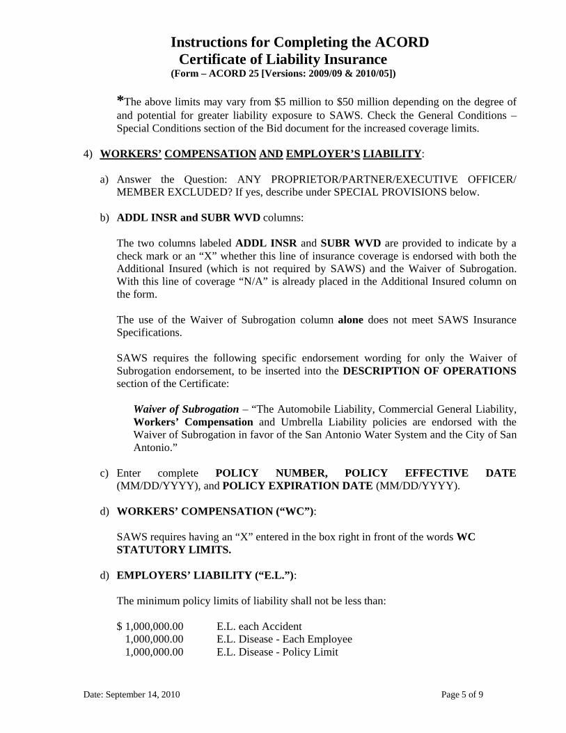
Instructions for Completing the ACORDCertificate of Liability Insurance
(Form – ACORD 25 [Versions: 2009/09 & 2010/05])
*The above limits may vary from $5 million to $50 million depending on the degree ofand potential for greater liability exposure to SAWS. Check the General Conditions –Special Conditions section of the Bid document for the increased coverage limits.
4) WORKERS’ COMPENSATION AND EMPLOYER’S LIABILITY:
a) Answer the Question: ANY PROPRIETOR/PARTNER/EXECUTIVE OFFICER/MEMBER EXCLUDED? If yes, describe under SPECIAL PROVISIONS below.
b) ADDL INSR and SUBR WVD columns:
The two columns labeled ADDL INSR and SUBR WVD are provided to indicate by acheck mark or an “X” whether this line of insurance coverage is endorsed with both theAdditional Insured (which is not required by SAWS) and the Waiver of Subrogation.With this line of coverage “N/A” is already placed in the Additional Insured column onthe form.
The use of the Waiver of Subrogation column alone does not meet SAWS InsuranceSpecifications.
SAWS requires the following specific endorsement wording for only the Waiver ofSubrogation endorsement, to be inserted into the DESCRIPTION OF OPERATIONSsection of the Certificate:
Waiver of Subrogation – “The Automobile Liability, Commercial General Liability,Workers’ Compensation and Umbrella Liability policies are endorsed with theWaiver of Subrogation in favor of the San Antonio Water System and the City of SanAntonio.”
c) Enter complete POLICY NUMBER, POLICY EFFECTIVE DATE(MM/DD/YYYY), and POLICY EXPIRATION DATE (MM/DD/YYYY).
d) WORKERS’ COMPENSATION (“WC”):
SAWS requires having an “X” entered in the box right in front of the words WCSTATUTORY LIMITS.
d) EMPLOYERS’ LIABILITY (“E.L.”):
The minimum policy limits of liability shall not be less than:
$ 1,000,000.00 E.L. each Accident 1,000,000.00 E.L. Disease - Each Employee 1,000,000.00 E.L. Disease - Policy Limit
Date: September 14, 2010 Page 5 of 9
Instructions for Completing the ACORDCertificate of Liability Insurance
(Form – ACORD 25 [Versions: 2009/09 & 2010/05])
5) Row of blank cells located immediately below the WORKERS COMPENSATIONANDEMPLOYERS” LIABILITY row:
a) This empty slot of spaces is typically used for such lines of coverage asPROFESSIONAL (Engineer’s & Architect’s E&O) LIABILITY, CONTRACTOR’SPOLLUTION LIABILITY, COMMERCIAL CRIME and/or BUILDER’S RISK lines ofinsurance coverage.
b) ADDL INSR and SUBR WVD columns:
The two columns labeled ADDL INSR and SUBR WVD are provided to indicate by acheck mark or an “X” whether this line of insurance coverage is endorsed with both theAdditional Insured and the Waiver of Subrogation.
Since SAWS does not require the PROFESSIONAL (Engineer’s & Architect’s E&O)LIABILITY, CONTRACTOR’S POLLUTION LIABILITY, COMMERCIAL CRIMEand/or BUILDER’S RISK lines of insurance coverage to be endorsed with either of theAdditional Insured or the Waiver of Subrogation endorsements, do not place anything ineither of the ADDL INSR or SUBR WVD columns.
c) Enter complete POLICY NUMBER, POLICY EFFECTIVE DATE(MM/DD/YYYY), and POLICY EXPIRATION DATE (MM/DD/YYYY).
d) The minimum limits (the per occurrence/claims-reported limit as well as the policyaggregate limit) for whichever TYPE OF INSURANCE coverage you are declaring inthis OTHER space must match with or exceed limits stated in the InsuranceSpecifications/Requirements contained in the respective Construction Bid, RFP or RFQdocument.
NOTE:
1. If the line of insurance coverage is either for Professional Liability or Contractor’sPollution Liability, identify in the DESCRIPTION OF OPERATIONS section ofthe Certificate the coverage form under which the respective line of coverage iswritten – either:
a. Claims-made form; or
b. Occurrence basis.
2. In instances where the coverage form used is Claims-made include the “Retro-Active date” according to the following:
Date: September 14, 2010 Page 6 of 9

Instructions for Completing the ACORDCertificate of Liability Insurance
(Form – ACORD 25 [Versions: 2009/09 & 2010/05])
a. For all contracts requiring Professional Liability and/or Contractor’s PollutionLiability coverage, the “Retro-Active date” shall be the Project start date orearlier and must be identified in the DESCRIPTION OF OPERATIONS sectionof the Certificate.
b. That date must be maintained (carried forward) as the “Retro-Active date”throughout the life of the Project/Contract to include the two-year warranty period(if required) following the close out of the Project/Contract.
3. If the Occurrence based coverage form is declared, no further information is required;and
4. If the Contractor’s Pollution Liability insurance coverage is required, the policy shallbe endorsed to provide transportation coverage beyond the boundaries of the job site– the following statement noting this endorsement shall be placed in theDESCRIPTION OF OPERATIONS section of the Certificate;
“Contractor’s Pollution Liability insurance coverage is endorsed to providetransportation coverage beyond the boundaries of the job site.”
If the Contractor’s Pollution Liability policy is not endorsed to providetransportation coverage beyond the boundaries of the job site then theCommercial/Business Automobile Liability policy must have the CA9948endorsement (“Pollution Liability – Broadened Coverage for Covered Autos –Business Auto, Motor Carrier and Truckers Coverage” forms) - the followingstatement noting this endorsement shall be placed either in the blank area just belowthe NON_OWNED AUTOS wording on the Certificate or in the DESCRIPTIONOF OPERATIONS section of the Certificate:
“Contractor’s Commercial/Business Automobile Liability insurance coverage isendorsed with the CA9948 endorsement to provide transportation coverage beyondthe boundaries of the job site.”
Policy must also be endorsed with MCS90 endorsement when hazardous material(s)are being transported.
7. DESCRIPTION OF OPERATIONS/LOCATIONS/VEHICLES/EXCLUSIONSADDED BY ENDORSEMENT/SPECIAL PROVISIONS
a. DESCRIPTION OF OPERATIONS:
1) Enter in this space the SAWS’ Job, Contract and/or Project number such as 09-1111 or P-09-011-MR;
Date: September 14, 2010 Page 7 of 9

Instructions for Completing the ACORDCertificate of Liability Insurance
(Form – ACORD 25 [Versions: 2009/09 & 2010/05])
2) The Project or Contract name may be included but is not required - such as “42” Water Mainreplacement Maltsberger from Loop 410 to U.S. 281 at Isom Road Engineering DesignProject or Construct 1 MG Composite Potable Water Elevated Storage Tank.
b. Where applicable or as needed, enter into this section, the DESCRIPTIONS of LOCATIONS,VEHICLES and/or EXCLUSIONS ADDED BY ENDORSEMENT.
c. DESCRIPTION OF SPECIAL PROVISIONS:
SPECIAL PROVISIONS to SAWS would include the wording for the Additional Insured andWaiver of Subrogation endorsements, declaring the type of policy coverage under which theProfessional and Contractor’s Pollution Liability policies are written, 30-day Notice ofCancelation, and other miscellaneous information that may be required; the wording may requirea second page to complete.
Special ENDORSEMENT’s wording required on the Certificate:
Additional Insured – “The Automobile Liability, Commercial General Liability andUmbrella Liability policies are endorsed naming the San Antonio Water System and the Cityof San Antonio as an Additional Insured.”
Waiver of Subrogation – “The Automobile Liability, Commercial General Liability,Workers’ Compensation and Umbrella Liability policies are endorsed with the Waiver ofSubrogation in favor of the San Antonio Water System and the City of San Antonio.”
30-day Notice of Cancelation – “Each of the above described policies is so endorsedrequiring SAWS and the City of San Antonio to be provided thirty (30) calendar days,advance written notice of any suspension, cancellation or non-renewal, and not less than ten(10) calendar days advance written notice for nonpayment of premium.”
8. CERTIFICATE HOLDER
SAWS shall be shown as the Certificate Holder in the Certificate Holder section located in thebottom half of the standard ACORD Certificate forms as follows:
San Antonio Water Systemc/o Ebix BPOPO Box 257Ref. # 107- (SAWS Contract/Bid/Project #)Portland, MI 48875-0257
Date: September 14, 2010 Page 8 of 9

Instructions for Completing the ACORDCertificate of Liability Insurance
(Form – ACORD 25 [Versions: 2009/09 & 2010/05])
Date: September 14, 2010 Page 9 of 9
9. CANCELLATION
Despite the wording in this section of the Certificate SAWS requires the following wording to beinserted into the DESCRIPTION OF OPERATIONS section of the Certificate:
30-day Notice of Cancelation – “Each of the above described policies is so endorsed requiringSAWS and the City of San Antonio to be provided thirty (30) calendar days, advance writtennotice of any suspension, cancellation or non-renewal, and not less than ten (10) calendar daysadvance written notice for nonpayment of premium.”
10.AUTHORIZED REPRESENTATIVE
The original certificate(s) or form must include at least one of the below acceptablenames/signatures:
a. Agency’s Authorized person’s (wet or stamped) signature;b. Agent's (wet or stamped) signature; orc. Agent's typed in name.

CERTIFICATE HOLDER
© 1988-2009 ACORD CORPORATION. All rights reserved.ACORD 25 (2009/09)
AUTHORIZED REPRESENTATIVE
CANCELLATION
DATE (MM/DD/YYYY)CERTIFICATE OF LIABILITY INSURANCE
LOCJECTPRO-POLICY
GEN'L AGGREGATE LIMIT APPLIES PER:
OCCURCLAIMS-MADE
COMMERCIAL GENERAL LIABILITY
GENERAL LIABILITY
PREMISES (Ea occurrence) $DAMAGE TO RENTEDEACH OCCURRENCE $
MED EXP (Any one person) $
PERSONAL & ADV INJURY $
GENERAL AGGREGATE $
PRODUCTS - COMP/OP AGG $
$RETENTION
DEDUCTIBLE
CLAIMS-MADE
OCCUR
$
$
AGGREGATE $
EACH OCCURRENCE $UMBRELLA LIAB
EXCESS LIAB
DESCRIPTION OF OPERATIONS / LOCATIONS / VEHICLES (Attach ACORD 101, Additional Remarks Schedule, if more space is required)
INSRLTR TYPE OF INSURANCE POLICY NUMBER
POLICY EFF(MM/DD/YYYY)
POLICY EXP(MM/DD/YYYY) LIMITS
WC STATU-TORY LIMITS
OTH-ER
E.L. EACH ACCIDENT
E.L. DISEASE - EA EMPLOYEE
E.L. DISEASE - POLICY LIMIT
$
$
$
ANY PROPRIETOR/PARTNER/EXECUTIVE
If yes, describe underDESCRIPTION OF OPERATIONS below
(Mandatory in NH)OFFICER/MEMBER EXCLUDED?
WORKERS COMPENSATIONAND EMPLOYERS' LIABILITY Y / N
AUTOMOBILE LIABILITY
ANY AUTO
ALL OWNED AUTOS
SCHEDULED AUTOS
HIRED AUTOS
NON-OWNED AUTOS
$
COMBINED SINGLE LIMIT(Ea accident)
BODILY INJURY (Per person)
BODILY INJURY (Per accident)
PROPERTY DAMAGE(Per accident) $
$
$
$
THIS IS TO CERTIFY THAT THE POLICIES OF INSURANCE LISTED BELOW HAVE BEEN ISSUED TO THE INSURED NAMED ABOVE FOR THE POLICY PERIODINDICATED. NOTWITHSTANDING ANY REQUIREMENT, TERM OR CONDITION OF ANY CONTRACT OR OTHER DOCUMENT WITH RESPECT TO WHICH THISCERTIFICATE MAY BE ISSUED OR MAY PERTAIN, THE INSURANCE AFFORDED BY THE POLICIES DESCRIBED HEREIN IS SUBJECT TO ALL THE TERMS,EXCLUSIONS AND CONDITIONS OF SUCH POLICIES. LIMITS SHOWN MAY HAVE BEEN REDUCED BY PAID CLAIMS.
INSRADDL
WVDSUBR
N / A
$
$
THIS CERTIFICATE IS ISSUED AS A MATTER OF INFORMATION ONLY AND CONFERS NO RIGHTS UPON THE CERTIFICATE HOLDER. THISCERTIFICATE DOES NOT AFFIRMATIVELY OR NEGATIVELY AMEND, EXTEND OR ALTER THE COVERAGE AFFORDED BY THE POLICIESBELOW. THIS CERTIFICATE OF INSURANCE DOES NOT CONSTITUTE A CONTRACT BETWEEN THE ISSUING INSURER(S), AUTHORIZEDREPRESENTATIVE OR PRODUCER, AND THE CERTIFICATE HOLDER.IMPORTANT: If the certificate holder is an ADDITIONAL INSURED, the policy(ies) must be endorsed. If SUBROGATION IS WAIVED, subject tothe terms and conditions of the policy, certain policies may require an endorsement. A statement on this certificate does not confer rights to thecertificate holder in lieu of such endorsement(s).
The ACORD name and logo are registered marks of ACORD
COVERAGES CERTIFICATE NUMBER: REVISION NUMBER:
INSURED
PHONE(A/C, No, Ext):
PRODUCER
PRODUCERCUSTOMER ID #:
ADDRESS:E-MAIL
FAX(A/C, No):
CONTACTNAME:
NAIC #
INSURER A :
INSURER B :
INSURER C :
INSURER D :
INSURER E :
INSURER F :
INSURER(S) AFFORDING COVERAGE
SHOULD ANY OF THE ABOVE DESCRIBED POLICIES BE CANCELLED BEFORETHE EXPIRATION DATE THEREOF, NOTICE WILL BE DELIVERED INACCORDANCE WITH THE POLICY PROVISIONS.

CERTIFICATE HOLDER
© 1988-2010 ACORD CORPORATION. All rights reserved.ACORD 25 (2010/05)
AUTHORIZED REPRESENTATIVE
CANCELLATION
DATE (MM/DD/YYYY)CERTIFICATE OF LIABILITY INSURANCE
LOCJECTPRO-POLICY
GEN'L AGGREGATE LIMIT APPLIES PER:
OCCURCLAIMS-MADE
COMMERCIAL GENERAL LIABILITY
GENERAL LIABILITY
PREMISES (Ea occurrence) $DAMAGE TO RENTEDEACH OCCURRENCE $
MED EXP (Any one person) $
PERSONAL & ADV INJURY $
GENERAL AGGREGATE $
PRODUCTS - COMP/OP AGG $
$RETENTIONDED
CLAIMS-MADE
OCCUR
$
AGGREGATE $
EACH OCCURRENCE $UMBRELLA LIAB
EXCESS LIAB
DESCRIPTION OF OPERATIONS / LOCATIONS / VEHICLES (Attach ACORD 101, Additional Remarks Schedule, if more space is required)
INSRLTR TYPE OF INSURANCE POLICY NUMBER
POLICY EFF(MM/DD/YYYY)
POLICY EXP(MM/DD/YYYY) LIMITS
WC STATU-TORY LIMITS
OTH-ER
E.L. EACH ACCIDENT
E.L. DISEASE - EA EMPLOYEE
E.L. DISEASE - POLICY LIMIT
$
$
$
ANY PROPRIETOR/PARTNER/EXECUTIVE
If yes, describe underDESCRIPTION OF OPERATIONS below
(Mandatory in NH)OFFICER/MEMBER EXCLUDED?
WORKERS COMPENSATIONAND EMPLOYERS' LIABILITY Y / N
AUTOMOBILE LIABILITY
ANY AUTOALL OWNED SCHEDULED
HIRED AUTOSNON-OWNED
AUTOS AUTOS
AUTOS
COMBINED SINGLE LIMIT
BODILY INJURY (Per person)
BODILY INJURY (Per accident)PROPERTY DAMAGE $
$
$$
THIS IS TO CERTIFY THAT THE POLICIES OF INSURANCE LISTED BELOW HAVE BEEN ISSUED TO THE INSURED NAMED ABOVE FOR THE POLICY PERIODINDICATED. NOTWITHSTANDING ANY REQUIREMENT, TERM OR CONDITION OF ANY CONTRACT OR OTHER DOCUMENT WITH RESPECT TO WHICH THISCERTIFICATE MAY BE ISSUED OR MAY PERTAIN, THE INSURANCE AFFORDED BY THE POLICIES DESCRIBED HEREIN IS SUBJECT TO ALL THE TERMS,EXCLUSIONS AND CONDITIONS OF SUCH POLICIES. LIMITS SHOWN MAY HAVE BEEN REDUCED BY PAID CLAIMS.
INSRADDL
WVDSUBR
N / A
$
$
(Ea accident)
(Per accident)
THIS CERTIFICATE IS ISSUED AS A MATTER OF INFORMATION ONLY AND CONFERS NO RIGHTS UPON THE CERTIFICATE HOLDER. THISCERTIFICATE DOES NOT AFFIRMATIVELY OR NEGATIVELY AMEND, EXTEND OR ALTER THE COVERAGE AFFORDED BY THE POLICIESBELOW. THIS CERTIFICATE OF INSURANCE DOES NOT CONSTITUTE A CONTRACT BETWEEN THE ISSUING INSURER(S), AUTHORIZEDREPRESENTATIVE OR PRODUCER, AND THE CERTIFICATE HOLDER.IMPORTANT: If the certificate holder is an ADDITIONAL INSURED, the policy(ies) must be endorsed. If SUBROGATION IS WAIVED, subject tothe terms and conditions of the policy, certain policies may require an endorsement. A statement on this certificate does not confer rights to thecertificate holder in lieu of such endorsement(s).
The ACORD name and logo are registered marks of ACORD
COVERAGES CERTIFICATE NUMBER: REVISION NUMBER:
INSURED
PHONE(A/C, No, Ext):
PRODUCER
ADDRESS:E-MAIL
FAX(A/C, No):
CONTACTNAME:
NAIC #
INSURER A :
INSURER B :
INSURER C :
INSURER D :
INSURER E :
INSURER F :
INSURER(S) AFFORDING COVERAGE
SHOULD ANY OF THE ABOVE DESCRIBED POLICIES BE CANCELLED BEFORETHE EXPIRATION DATE THEREOF, NOTICE WILL BE DELIVERED INACCORDANCE WITH THE POLICY PROVISIONS.

SEALE GST NO. 1 PAINTING SUPPLEMENTARY CONDITIONS& REHABILITATION PROJECT AUGUST 2012
SUC-1
SUPPLEMENTARY CONDITIONS
SCOPE: The Supplementary Conditions amend the General Conditions and the otherprovisions of the Contract Documents as indicated herein. All provisions whichare not so amended or supplemented remain in full force and effect.
SUC 1.0 CONTRACT ADMINISTRATION
SUC 1.1 Subcontractors: Article IV, paragraph 4.6 of these Contract Documents is amended as follows:
“The Contractor shall perform the Work with its own organization on at least 40% of thetotal original contract price. The term to “perform the Work with its own organization” isdefined herein as utilizing only:
Workers employed and paid directly by the Contractor or a wholly ownedsubsidiary of the Contractor.
Equipment owned by the Contractor or its wholly owned subsidiary.
Rented or leased equipment operated by the Contractor’s, or its wholly ownedsubsidiaries, employees.
For purposes of determining the value of the Work self performed, the amountshall include all materials incorporated into the Work where the majority of thevalue of the Work involved in incorporating the material is performed by theContractor’s own Organization, including wholly owned subsidiary; and
Labor provided by staff leasing firms licensed under Chapter 91 of the TexasLabor code for non supervisory personnel if the contractor or wholly ownedsubsidiary maintains direct control over the labor.”
SUC 2.0 CONTRACT RESPONSIBILITIES
SUC 2.1 Owner’s Responsibility: Article V, paragraph 5.2.3 of the General Conditions of these Contract Documents is
amended as follows: strike paragraph 5.2.3 in its entirety and replace as follows:
“Materials testing is defined in the Technical Specifications, Section 01400 – QualityControl.”
SUC 2.2 Superintendent:Article V, paragraph 5.4 of the General Conditions of these Contract Documents isamended as follows: strike paragraph 5.4 in its entirety and replace as follows:

SEALE GST NO. 1 PAINTING SUPPLEMENTARY CONDITIONS& REHABILITATION PROJECT AUGUST 2012
SUC-2
“The Contractor shall keep on-site for this Project during its progress a competentSuperintendent who is a direct employee of the prime contractor and any necessaryassistants, all satisfactory to the Owner. A Superintendent shall be identified in writing tothe Vice President of Engineering or his duly authorized representative, promptly afterOwner issued written Authorization to Proceed. The Superintendent shall represent theContractor and all directions given to him shall be binding. Other Oral directions fromthe SAWS representatives involving critical situations or Work elements shall beimmediately confirmed in writing by Owner to the Contractor. The Contractor’sSuperintendent shall provide full-time onsite supervision to any Work ongoing at the siteby its own forces or subcontractors, using the best skill and attention. The appointmentof a designee in lieu of a full time superintendent shall not be allowed as part of thisprovision, therefore any reference to “designee” shall not be applicable.”
SUC 2.3 Disposal of Non-Hazardous Waste Material/Substances:Article V, paragraph 5.9.4 of the General Conditions of these Contract Documents isamended as follows: strike paragraph 5.9.4 in its entirety and replace as follows:
“The Contractor shall be responsible for disposing of all non-hazardous materialas the term is defined in Article I herein including old concrete or any other non-hazardous material which is required to be removed from the project inaccordance with local, state and federal regulations. All completed bills of lading,manifests or other shipping documents for this material will be provided to SAWSat no additional cost to the Owner. Such material shall not be deposited in anysanitary sewer, creek, river, water course or municipal separate, storm sewersystem, (MS4) as the term is defined herein.”
SUC 2.4 Disposal of Hazardous Waste Material/Substances:Article V, paragraph 5.9.5 of the General Conditions of these Contract Documents isamended as follows: strike paragraph 5.9.5 in its entirety and replace as follows:
“Contractor will advise SAWS of final disposition of hazardous wastes prior to hazardouswaste disposal, and provide documentation at that time which shows transporters anddisposal facilities are permitted for their respective activities. All completed hazardouswaste manifests will be provided to SAWS” with no additional cost to the Owner.”
SUC 2.5 Testing:Article V, paragraph 5.10 of the General Conditions of these Contract Documents isamended as follows: strike the last sentence of the paragraph.
SUC 2.6 Construction Stakes:Article V, paragraph 5.16 of the General Conditions of these Contract Documents isamended as follows: strike paragraph 5.16 in its entirety and replace with the following:
“5.16 CONSTRUCTION STAKES – Project controls shall be provided as detailed inspecification Section 01050 – Field Engineering. All construction staking shall beprovided by the Contractor.”
SEALE GST NO. 1 PAINTING SUPPLEMENTARY CONDITIONS& REHABILITATION PROJECT AUGUST 2012
SUC-3
SUC 2.7 Working Hours:Article V, paragraph 5.19 of the General Conditions of these Contract Documents isamended as follows: strike paragraph 5.19 in its entirety and replace as follows:
“Working Days: Working time on this project is Monday through Friday between 8:00AM and 5:00 PM. In addition to no work being permitted on Sundays and holidays, nowork shall occur on Saturdays without specific, written permission of the Owner forty-eight (48) hours in advance of intent to perform Work.”
SUC 2.8 Use of Explosives:Article V, paragraph 5.24 of the General Conditions of these Contract Documents isamended as follows: strike paragraph 5.24 in its entirety and replace as follows:
“5.24 USE OF EXPLOSIVES - The use of explosives of any kind for this project isstrictly prohibited.”
SUC 2.9 Safety Precautions and Programs:Article V, paragraph 5.29 of the General Conditions of these Contract Documents isamended as follows: in addition to the requirements of Article V, paragraph 5.29 of theGeneral Conditions of these Contract Documents, also refer to SAWS ConstructionSpecification #902, Safety and Health, and SAWS Construction Safety and HealthProgram, Sept. 2007.
SUC 3.0 CONTRACT COMPLETION TIME
SUC 3.1 Performance Time:Article VIII, paragraph 8.3 of the General Conditions of these Contract Documents isamended as follows: Amend paragraph 8.3.1 as follows:
“Normal adverse weather conditions anticipated during the period covered by this workwhich impede progress on projects of this nature have been included in the calculation ofdays allowed to complete this Work. There shall be no additional contract time grantedexcept in the case of severe weather conditions at such time the Contractor shall address arequest to SAWS, in writing, specifically outlining the request for contract time withattached local area National Weather Data.”
SUC 4.0 PROJECT COMPLETION AND ACCEPTANCE
SUC 4.1 Partial Acceptance: Article IX, paragraph 9.2 of the General Conditions of these Contract Documents is
amended as follows: amend paragraph 9.2.1 as follows:
“The Contractor will be considered to be substantially complete:A. When he/she has completed the Work, demobilized and begun restoration of
ground grass cover.B. Upon receipt of a passing bacteriological and Volatile Organic Compound
(VOC) sample of water in the tank after disinfection and filling have occurred.”
END OF SUPPLEMENTARY CONDITIONS

This page intentionally left blank.

SEALE GST NO. 1 PAINTING SPECIAL CONDITIONS& REHABILITATION PROJECT AUGUST 2012
SPC-1
SPECIAL CONDITIONS
SPC 1.0 CONSTRUCTION MATERIALS
SPC 1.1 Equivalent Materials and Equipment:Requests for review of equivalency will not be accepted from anyone except the Contractor,and such requests will not be accepted until after the Contract has been awarded.
SPC 2.0 PROJECT REQUIREMENTS
SPC 2.1 Pre-Proposal Conference / Site Inspection:A mandatory pre-proposal conference will be conducted in accordance with the Invitationfor Competitive Sealed Proposals. Pursuant to the Instructions to Respondents, eachrespondent shall determine, for him/herself by examination at the site of the Work, theconditions which exist and under which he/she will be expected to perform the Work. Priorto presenting their Proposal, Respondents are encouraged to take their own representativesamples of the existing coating system: e.g. exterior, interior, and piping coating system andtest samples in a state certified laboratory for total lead, chromium and cadmium and use theirbest judgment in determining their construction method, labor hazard protection, equipmentand materials to perform the Work in full compliance with TCEQ, EPA and OSHAregulations. It will be presumed that the necessary examination, samples, and testing havebeen conducted prior to Respondents submitting their Proposal for consideration.
A mandatory pre-proposal site inspection will be conducted at the Seale Pump Stationproject site the day of the pre-proposal conference. See the Invitation for Competitive SealedProposals for times and dates of the meetings.
SPC 2.2 Special Construction Requirements:The project drawings and specifications reference the results of limited testing conducted atthe tank site. This information is limited and is intended only to determine apparenthazardous materials such as heavy metals in existing coatings on the tank and facility piping.The Contractor will have to conduct his own assessment of the materials on the site. Theinformation included in the project drawings and specifications is limited in scope and shallnot to be considered a comprehensive environmental assessment of the site. The Contractorshall consult Section 01060 - Regulatory Requirements and Section 09940 - Removal of LeadBased Coatings regarding his/her responsibilities.
SPC 3.0 THREATENED OR ENDANGERED SPECIES AND MIGRATING BIRDS
SPC 3.1 If Contractor encounters any nesting birds listed as threatened or endangered species, he shallnotify the Owner prior to taking any action.
A. The Contractor is responsible to take measures necessary to prevent establishment of anymigratory, threatened or endangered birds nesting on the structure during his constructionwhich would be negatively impacted by the construction activities.
END OF SPECIAL CONDITIONS

This page intentionally left blank.

SEALE GST NO. 1 PAINTNG SUMMARY OF WORK& REHABILITATOIN PROJECT AUGUST 2012
01010 - 1
SECTION 01010
SUMMARY OF WORK
PART 1 GENERAL
1.01 GENERAL CONDITIONS:
A. The CONTRACTOR shall include in the Price Proposal all labor, equipment, material,tools, supplies, and incidentals necessary to complete all work required by this Contractin accordance with the latest Standard Specifications for Water Works Construction.
B. All work done under this Contract shall conform to all local ordinances.CONTRACTOR shall arrange and pay all cost of permits and inspection fees, and shallconfine his operations to the limits set by law.
C. The CONTRACTOR shall take care to protect existing trees in accordance with the latestrequirements of the City of San Antonio Tree Preservation Ordinance No. 85262 (datedMarch 13, 2003 or latest revision). CONTRACTOR shall provide the required treeprotection plan to avoid damage to mature trees and native brush and shall replace anyvegetation that requires removal with equivalent vegetation unless such vegetation isspecifically noted for removal on the Contract Drawings.
D. It is the intent of the Owner to award this project to one CONTRACTOR.
E. Portions of this project may be subject to review and acceptance by various agencies.The CONTRACTOR will be required to coordinate with these agencies for such items asissuance of permits or work order inspections during construction, and final acceptance.The agencies for this project that may require coordination include, but are not limited to,the following:
1. Texas Commission on Environmental Quality
2. City of San Antonio Public Works Department
3. San Antonio Water System
1.02 EXISTING CONDITIONS:
A. Project Location: The Seale No. 1 Tank site is located at 254 Seale Road in San Antonio,TX, 78219. The tank is a 3.0 MG, welded steel, ground storage tank. The tank has a sidewater depth of 64 ft. and a diameter of 90 ft. The tank was constructed in 1994 byAdvanced Tank and Construction Co.
B. Existing Utilities: Locate and protect all existing utilities impacted by this project.Those affected by this project may include, but are not limited to, the following:
1. San Antonio Water System
2. CPS Energy
3. Southwestern Bell Telephone

SEALE GST NO. 1 PAINTNG SUMMARY OF WORK& REHABILITATOIN PROJECT AUGUST 2012
01010 - 2
4. AT&T Communications
5. Grande Cable
6. Others as indicated on the Contract Drawings
1.03 DESCRIPTION OF WORK:
A. Seale No. 1 Tank: The Work covered under this contract includes, but is not limited to,the following:
1. Ground Storage Tank: Complete SSPC-SP-10 cleaning and repainting of interiorsurfaces and the complete SSPC-SP-6 cleaning and repainting of the exterior surfaceswith full containment as outlined in SSPC Guide 6 Class 2A.
2. Additional ground storage tank rehabilitation Work items:i. replacement of all interior bolts at the interface between the tank shell and
the roof girders;ii. installation of a new interior ladder with safety cable climb;
iii. installation of a new cathodic protection system;iv. installation of new level electrodes;v. installation of a new aluminum roof center vent;
vi. replacement of screens on the exterior goose neck vents;vii. installation of new roof access hatches and safety railing;
viii. installation of a new exterior ladder parapet;ix. new sample taps and pressure gauge;x. replacement of butterfly valves on tank inlets from well field;
xi. replacement of tank drain valves;xii. relocation of electrical and instrumentation control systems; and
xiii. other improvements as indicated on the Contract Drawings.
3. Yard Piping: Complete SSPC SP-3 and SP-11 power tool cleaning and repainting ofthe exterior surfaces as indicated on the Contract Drawings on the following: ASRyard piping; well pump and piping assemblies 2, 3 and 4; and high service pump andpiping assemblies 1 through 5.
i. Testing has shown heavy metals to be present on Well #3 pump and pipeassembly coatings:
a. Well Pump # 3 Coatings:115,000 mg/kg lead 1,700 mg/kg chromium 8.76 mg/kg cadmium
ii. Cleaning and repainting of the exterior surfaces of the Well Pump #3 pumpand pipe assembly shall require a full containment as outlined in SSPCGuide 6 Class 1A.
4. Additional site improvement Work items include:i. installation of new mag meters on the high service pump assemblies 1-5;
ii. replacement of check valves on high service pump assembly 4 and 5;iii. replacement of existing perimeter fence;iv. replacement of exterior access gates;v. repaving of asphalt access drive around tank;
vi. site grading, drainage and re-vegetation work;vii. installation of a new shade canopy over existing MCC switchgear;

SEALE GST NO. 1 PAINTNG SUMMARY OF WORK& REHABILITATOIN PROJECT AUGUST 2012
01010 - 3
viii. chlorine system upgrades and replacement of chlorine vaults;ix. installation of new division valve vault; andx. other miscellaneous improvements as noted on the Contract Drawings.
B. Sample test results for heavy metals as provided above are included for the Contractor’sreference only; he/she is responsible to conduct his/her own investigation and samplingas necessary to prepare the Price Proposal. All waste material is considered to behazardous and handled as such by the Contractor, until such time as it tested anddetermined to be non-hazardous or rendered as such by the Contractor. The Contractorwill be required to test the waste and provide results regarding leachable metals prior todisposal.
The Contractor is responsible to prepare a plan of means and methods ensuring that thetank rehabilitation work does not increase the soil background levels or spreadcontaminated soil, and protects workers and the public. Background levels of heavymetals on the ground at the site will be measured by the Contractor prior to start ofconstruction and tested at the completion of construction to ensure no increases.
C. Performance Time: All work indicated in the Contract Documents shall be substantiallycomplete, as defined in this Section, and ready for SAWS use by the time as specified inthe Price Proposal. For every calendar day the work is incomplete beyond the abovespecified times the CONTRACTOR shall be made liable to the San Antonio WaterSystem for Liquidated Damages in accordance with Article VIII, paragraph 8.6 of theGeneral Conditions of these Contract Documents and any revisions to said GeneralConditions as documented in the Supplementary Conditions.
Normal adverse weather conditions anticipated during the period covered by this work,which might impede progress on projects of this nature, have been included in thecalculation of days allowed to complete this work. There shall be no additional timegranted except in the case of severe weather conditions at such time the CONTRACTORshall address a request to SAWS, in writing, specifically outlining the request foradditional contract time.
D. Substantial Completion: A Certificate of Substantial Completion will be issued uponinstallation and successful operation of all valves, piping, electrical controls andinstrumentation, and receipt of a passing bacteriological and Volatile Organic Compound(VOC) sample of water in the tank after disinfection and filling have occurred.
1.04 WORK SEQUENCE:
A. Construct work in stages to provide proper coordination with work by others. Coordinatethe construction schedule and operations with the Owner's representative. Reference toArticle V, paragraph 5.15 of the General Conditions and Section 01040 – Coordination.
1.05 CONTRACTOR'S USE OF PREMISES:
A. CONTRACTOR shall limit his use of the premises for work and for storage, to allow forwork by other Contractors.
B. Coordinate use of premises under direction of Owner.

SEALE GST NO. 1 PAINTNG SUMMARY OF WORK& REHABILITATOIN PROJECT AUGUST 2012
01010 - 4
C. CONTRACTOR assumes full responsibility for the protection and safekeeping ofproducts under this Contract stored on the site.
D. Move any stored products, under CONTRACTOR's control, which interfere withoperations of the Owner or separate Contractor.
E. CONTRACTOR to obtain and pay for the use of additional storage or work areas neededfor operations.
F. Contractor will NOT be allowed to plug into any on site power. Should theCONTRACTOR need power for work operations, he/she will be required to provide attheir own expense.
G. The CONTRACTOR will provide temporary electric power to the site by CPS Energy fortheir use in completing the Work. The cost of said temporary electric power by CPSEnergy shall be the CONTRACTOR’s responsibility. The running of electric line(s)within the site, from the CPS power source to the project site, shall be the responsibilityof the CONTRACTOR. The cost of which shall be included and a part of the project’slump sum bid item. CONTRACTOR shall be responsible for power until such time asSAWS accepts the project and all related operations and maintenance manuals.
H. CONTRACTOR is responsible for preparing a traffic control plan and submitting theplan for City of San Antonio approval for all work in public streets. The CONTRACTORwill provide all signs, barricades and required off-duty police officers as part of his basebid. The CONTRACTOR shall not begin construction of the Project or close any streetsuntil adequate barricades and detour signs have been provided, erected and maintained inaccordance with the details shown on the Plans. The CONTRACTOR shall notify theOwner forty-eight (48) hours in advance of closing any street to through traffic. Localtraffic shall be permitted the use of streets under construction where feasible.
PART 2 PRODUCTSA. All products incorporated into the work area shall be new, unused, and first quality.
PART 3 EXECUTION
A. All work shall be performed in a workmanlike manner by properly trained and qualifiedpersonnel under supervision of the Contractor’s Representative.
B. All work done under this Contract shall conform to all local ordinances. TheCONTRACTOR shall arrange and pay for all cost of permits and inspection fees andshall confine his/her operations to the limits set by law.
C. The CONTRACTOR shall comply with all local and state rules and regulations thatgovern the San Antonio Water System.

SEALE GST NO. 1 PAINTNG SUMMARY OF WORK& REHABILITATOIN PROJECT AUGUST 2012
01010 - 5
PART 4 WARRANTY
A. The CONTRACTOR shall warrant the coating system for a minimum of two (2) years inaccordance with Section 09800. The remainder of the work shall comply with SAWSstandard two (2) year warranty, described within the General Conditions of this Contract.
B. The CONTRACTOR is responsible for an anniversary inspection as outlined in Section09800 - General Specifications for Coating System.
END OF SECTION

This page intentionally left blank.

SEALE GST NO. 1 PAINTING USE OF PREMISES& REHABILITATION PROJECT AUGUST 2012
01015 - 1
SECTION 01015
USE OF PREMISES
PART 1 GENERAL
1.01 DESCRIPTION:
A. This section includes general use of the San Antonio Water System’s (SAWS) projectsite, including limits of construction, access to site, material storage and staging area aswell as State or City rights-of-way and utility easements.
1.02 CONSTRUCTION AREA:
A. Property address is 254 Seale Road, San Antonio, TX, 78219
1. Primary CONTRACTOR access to the site shall be from the access gate atSeale Road.
2. A secondary CONTRACTOR access to the site is available from the access gateat W.W. White Road. Access through this gate shall be limited and shall becoordinated with SAWS COI.
B. The CONTRACTOR will confine work to the limits of construction shown on theDrawings. Trespassing on abutting lands or other land in the area is not allowed. Referto Article IV, paragraph 4.11 of the General Conditions.
C. CONTRACTOR access to the SAWS Van Dyke Service Center facility is strictlyprohibited. Where access is required for fence removal and replacement, theCONTRACTOR shall coordinate with the SAWS COI.
D. CONTRACTOR will have limited use of the Seale Pump Station site for materialstorage; CONTRACTOR material storage and staging area shall be approved by theSAWS COI. The CONTRACTOR will be required to remove the materials onceconstruction is completed and restore the area with established grass cover. The drip lineof existing trees to remain shall be protected from vehicle traffic.
E. CONTRACTOR’s work shall not interfere with Owner’s operation and use of the SealePump Station or Van Dyke Service Center facilities. Excavations, stored equipment, andother nuisances shall not interfere with facility operations and the CONTRACTOR shallsafeguard personnel by maintaining reasonable warnings in accordance with Article V,paragraph 5.29 of the General Conditions. At Owner’s request, roadways temporarilyblocked by CONTRACTOR shall be cleaned and cleared to facilitate Owner’soperations.
F. At no time shall the site be left unattended by the CONTRACTOR without existing,temporary or permanent fencing, gates and locks in place. All temporary and permanentfencing shall meet TCEQ regulations.

SEALE GST NO. 1 PAINTING USE OF PREMISES& REHABILITATION PROJECT AUGUST 2012
01015 - 2
1.03 PROTECTION OF WORK AND PROPERTY
A. CONTRACTOR shall be responsible for taking all precautions, providing all programs,and taking all actions necessary to protect the Work and all public and private propertyand facilities from damage.
B. CONTRACTOR shall assume full responsibility for the preservation of all public andprivate property or facility on or adjacent to the site. If any direct or indirect damage isdone by or on account of any act, omission, neglect or misconduct in the execution of theWork by the CONTRACTOR, it shall be restored by the CONTRACTOR, at his expense,to a condition equal to that existing before the damage was done.
C. Perform daily clean-up of dirt, debris, scrap materials, and other disposable items. Keepstreets, driveways, and sidewalks clean of dirt, debris and scrap materials. Do not leavebuilding, roads, streets or other construction areas unclean overnight.
D. Underground Structures
1. Underground structures are defined to include, but not be limited to, all sewer,water, gas, and other piping, and manholes, chambers, electrical conduits,tunnels, vaults and other existing subsurface work located within or adjacent tothe Contract limits.
2. All underground structures known to Engineer except water, sewer, electric, andtelephone service connections are shown on the Drawings. This information isshown for the assistance of CONTRACTOR in accordance with the bestinformation available, but is not guaranteed to be correct or complete.
3. CONTRACTOR shall explore ahead of his trenching and excavation Work andshall uncover all obstructing underground structures sufficiently to determinetheir location, to prevent damage to them and to prevent interruption to theservices which such structures provide. If the CONTRACTOR damages anunderground structure, he shall restore it to original condition at his expense.
4. Necessary changes in the location of the Work may be made by Engineer, toavoid unanticipated underground structures.
5. If permanent relocation of an underground structure or other subsurface facility isrequired and is not otherwise provided for in the Contract Documents, Engineerwill direct CONTRACTOR in writing to perform the Work, which shall be paidfor under an agreed Change Order.
E. Surface Structures are defined as all existing buildings, structures and other facilitiesabove the ground surface. Included with such structures are their foundations or anyextension below the surface. Surface structures include, but are not limited to, buildings,houses, trailer homes, fences, tanks, walls, bridges, roads, dams, channels, open drainage,piping, poles, wires, posts, signs, markers, curbs, walks and all other facilities that arevisible above the ground surface.
F. Protection of Underground and Surface Structures:
1. CONTRACTOR shall sustain in their places and protect from direct or indirectinjury all underground and surface structures located within or adjacent to thelimits of the Work. Such sustaining and supporting shall be done carefully and

SEALE GST NO. 1 PAINTING USE OF PREMISES& REHABILITATION PROJECT AUGUST 2012
01015 - 3
as required by the party owning or controlling such structure. Before proceedingwith the work of sustaining and supporting such structure, CONTRACTOR shallsatisfy the Engineer that the methods and procedures to be used have beenapproved by the party owning same.
2. CONTRACTOR shall assume all risks attending the presence or proximity of allunderground and surface structures within or adjacent to the limits to the Work.CONTRACTOR shall be responsible for all damage and expense for direct orindirect injury caused by his Work to any structure. CONTRACTOR shall repairimmediately all damage caused by his work, to the satisfaction of the Owner ofthe damaged structure.
G. All other existing surface facilities, including, but not limited to, guard rails, posts,fences, gates, guard cables, signs, light poles, poles, markers, and curbs which aretemporarily removed to facilitate installation of the Work shall be replaced and restoredto their original condition at CONTRACTOR’s expense.
H. Protection of Installed Products
1. Provide protection of installed products to prevent damage from subsequentoperations. Remove protection facilities when no longer needed and prior tocompletion of Work.
2. Control traffic to prevent damage to equipment, materials, and surfaces.
3. Provide coverings to protect equipment and materials from damage. Coverprojections, wall corners, jambs, sills, and exposed sides of openings in areasused for traffic and for passage of materials in subsequent work.
1.04 NOTIFICATION TO ADJACENT OCCUPANTS
A. Notify individual occupants in areas to be effected by the Work of the proposedconstruction and time schedule. Notification shall be not less than 72 hours or more than2 weeks prior to work being performed within 200 feet of the homes or businesses.SAWS Engineer will provide a sample door hanger showing form and content to befollowed.
B. Include in notification names and telephone numbers of two company representatives forresident contact, who will be available on 24-hour call. Include precautions that will betaken to protect private property and identify potential access or utility inconvenience ordisruption.
C. Submit proposed notification to SAWS Engineer for approval. Consideration shall begiven to the ethnicity of the neighborhood where English is not the dominant language.Notice shall be in an understandable language.
1.05 SURFACE MAINTENANCE AND RESTORATION
A. CONTRACTOR shall maintain a clean and tidy site at all times. Contractor shall keepsite clean of rocks, tree branches, and debris during the entire contract period.CONTRACTOR shall be responsible for mowing the grass.
B. Restore site to condition existing before construction to satisfaction of SAWS Engineer.

SEALE GST NO. 1 PAINTING USE OF PREMISES& REHABILITATION PROJECT AUGUST 2012
01015 - 4
C. Repair paved area per the requirements of Section 02510 - Pavement Repair andResurfacing and in accordance with any applicable local, state or federal regulations.
D. Repair turf areas which become damaged, level with bank run sand conforming toSection 02480 – Landscaping. Water and level newly sodded areas with adjoining turfusing steel wheeler rollers appropriate for sodding. Do not use spot sodding or sprigging.
PART 2 PRODUCTS – NOT USED
PART 3 EXECUTION – NOT USED
END OF SECTION

SEALE GST NO. 1 PAINTING MEASUREMENT AND PAYMENT& REHABILITATION PROJECT AUGUST 2012
01025 - 1
SECTION 01025
MEASUREMENT AND PAYMENT
PART 1 GENERAL
1.01 DESCRIPTION OF WORK
A. This section defines the method that will be used to determine the quantities of Workperformed or materials supplied and establish the basis upon which payment will bemade.
1.02 ADMINISTRATIVE SUBMITTALS:
A. Schedule of Values: Submit schedule on CONTRACTOR's standard form. (Refer toparagraph 1.05 of this Section and Section 01300 – Submittals for additionalrequirements.)
B. Schedule of Estimated Progress Payments: (Refer to paragraph 1.06 of this Section foradditional requirements.)
1. Submit with initially acceptable Schedule of Values.
2. Submit adjustments thereto with Application for Payment.
C. Application for Payment.
D. Final Application for Payment.
1.03 RELATED WORK
A. Section 01300 – Submittals
1.04 PRICE
A. Required items of Work and incidentals necessary for the satisfactory completion of theProject shall be considered incidental to the specified Work required under this contractand shall be considered as included in the unit prices for the various proposal items. TheCONTRACTOR shall prepare his price accordingly to allow for such items:
1. Not specifically listed in the Price Proposal.
2. Not specified in this section to be measured or to be included in one of the itemslisted in the Price Proposal.
3. To include CONTRACTOR’s overhead and profit.
B. Work includes the furnishing of all labor, materials, equipment, tools, and related itemsfor performing all operations required to complete the Project satisfactorily in place, asspecified by the contract documents.

SEALE GST NO. 1 PAINTING MEASUREMENT AND PAYMENT& REHABILITATION PROJECT AUGUST 2012
01025 - 2
1.05 SCHEDULE OF VALUES:
A. Prepare a separate Schedule of Values for each phase of Work under the Agreement.Submit the Schedule of Values within 10 days prior to submitting the first request forpayment or as requested by the Owner.
B. Use line items in the proposal as line items in the schedule. Provide adequate detail toallow easy determination of the percentage of work completed for each item.
C. Lump Sum Work.
1. Reflect Schedule of Values format included in conformed Price Proposal Form,specified allowances, alternates, and equipment selected by Owner, as applicable.
2. List bonds and insurance premiums, mobilization, demobilization, facility startup,and contract closeout separately.
3. Separate product costs and installation costs. Break down by Division 2 through 16for each of the Project facilities.
a. Product costs include cost for product, delivery and unloading, royalties andpatent fees, taxes, and other cost paid directly to the supplier or vendor.
b. Installation costs include cost for the supervision, labor and supervision,labor and equipment for field fabrication, erection, installation, start-up,initial operation and CONTRACTOR’S overhead and profit.
4. Divide principal subcontract amounts into an adequate number of line items to allowdetermination of the percentage of work completed for each item. These line itemsmay be used to establish the value of work to be added or deleted from the project.
D. Unit Price Work: Reflect unit price quantity and price breakdown from conformed PriceProposal Form.
E. An unbalanced or front-end loaded schedule will not be acceptable.
F. Summation of the complete Schedule of Values representing all Work shall equal theContract Price.
G. Mobilization
1. Description – This item shall govern the mobilization of personnel, equipment andsupplies at the project site in preparation for the beginning work on contract itemsand the acquisition of insurance and bonds. Mobilization shall include, but not belimited to the movement of equipment, personnel, material, supplies, etc. to theproject site and the establishment of temporary offices and other facilities necessaryto the start of the work.
2. Measurement – Measurement of the item, “Mobilization” will be by the lump sum asthe work progresses. “Mobilization” lump sum price shall be limited to a maximum10% of the total contract amount.
3. Payment – Partial payments of the lump sum price for mobilization will be asfollows:
SEALE GST NO. 1 PAINTING MEASUREMENT AND PAYMENT& REHABILITATION PROJECT AUGUST 2012
01025 - 3
a. When 1% of the adjusted contract amount for construction items (which isdefined as the total contract amount less the lump sum bid for mobilization)is earned, 50% of the mobilization lump sum bid or 5% of the total contractamount, whichever is less, will be paid. Insurance and Bonds will be paid onthe initial request for payment under a sub-heading to mobilization entitled"Insurance and Bonds". The amount paid for insurance and bonds will notexceed 3% of the total contract amount for construction items. Receipts orother proof of payment for the full amount of compensation requested underthe sub-heading of “Insurance and Bonds” shall be provided to the Ownerwith the request for payment.
b. When 5% of the adjusted contract amount for construction items is earned,75% of the mobilization lump sum bid or 7.5% of the total contractamount, whichever is less will be paid.
c. When 10% of the adjusted contract amount for construction items isearned, 90% of the mobilization lump sum bid or 9% of the total contractamount, whichever is less will be paid.
d. Upon completion of all work under this contract, payment for theremainder of the lump sum bid for mobilization will be made.
e. Payment for this line item will be reduced by half of the earned amount,until said documents are submitted and approved by the Owner:i. All material submittals,
ii. Health and Safety Plan,iii. Quality Control / Quality Assurance Plan,iv. Pre-Construction Video, andv. Construction Schedule
1.06 SCHEDULE OF ESTIMATED PROGRESS PAYMENTS:
A. Show estimated payment requests throughout Contract Times aggregating initial ContractPrice.
B. Base estimated progress payments on initially acceptable progress schedule. Adjust toreflect subsequent adjustments in progress schedule and Contract Price as reflected bymodifications to the Contract Documents.
1.07 APPLICATION FOR PAYMENT:
A. Reference Article VII. CONTRACT PAYMENTS of the General Conditions.
B. Transmittal Summary Form: Attach one Summary Form with each detailed Applicationfor Payment for each schedule and include Request for Payment of Materials andEquipment on Hand as applicable. Execute certification by authorized officer ofCONTRACTOR.
C. Provide separate form for each schedule as applicable.

SEALE GST NO. 1 PAINTING MEASUREMENT AND PAYMENT& REHABILITATION PROJECT AUGUST 2012
01025 - 4
D. Include accepted Schedule of Values for each schedule or portion of Work, the unit pricebreakdown for Work to be paid on unit price basis, a listing of Owner-selected equipmentif applicable, and allowances, as appropriate.
E. Preparation:
1. Round values to nearest dollar.
2. List each Change Order and Written Amendment executed prior to date ofsubmission as separate line item. Totals to equal those shown on the TransmittalSummary Form for each schedule as applicable.
3. Submit Application for Payment, including a Transmittal Summary Form anddetailed Application for Payment Form(s) for each schedule as applicable, alisting of materials on hand for each schedule as applicable and such supportingdata as may be requested by Owner.
1.08 MEASUREMENT – GENERAL
A. Weighing, measuring, and metering devices used to measure quantity of materials forWork shall be suitable for purpose intended and conform to tolerances and specificationsas specified in National Institute of Standards and Technology, Handbook 44.
B. Whenever pay quantities of material are determined by weight, the material shall beweighed on scales furnished by CONTRACTOR and certified accurate by the stateagency responsible. A weight or load slip shall be obtained from the weigh facility anddelivered to the Owner's representative at the point of delivery of the material.
C. If material is shipped by rail, the car weights will be accepted provided that actual weightof material only will be paid for and not minimum car weight used for assessing freighttariff, and provided further that car weights will not be acceptable for material to bepassed through mixing plants.
D. Vehicles used to haul material being paid for by weight shall be weighed empty daily andat such additional times as required by Owner. Each vehicle shall bear a plainly legibleidentification mark.
E. All materials that are specified for measurement by the cubic yard measured in thevehicle shall be hauled in vehicles of such type and size that the actual contents may bereadily and accurately determined. Unless all vehicles are of uniform capacity, eachvehicle must bear a plainly legible identification mark indicating its water level capacity.All vehicles shall be loaded to at least their water level capacity. Loads hauled in vehiclesnot meeting the above requirements or loads of a quantity less than the capacity of thevehicle, measured after being leveled off as above provided, will be subject to rejection,and no compensation will be allowed for such material.
F. Quantities will be based on ground profiles shown. Field surveys will not be made toconfirm accuracy of elevations shown.
G. Where measurement of quantities depends on elevation of existing ground, elevationsobtained during construction will be compared with those shown on Drawings.Variations of one foot or less will be ignored, and profiles shown on Drawings will beused for determining quantities.
SEALE GST NO. 1 PAINTING MEASUREMENT AND PAYMENT& REHABILITATION PROJECT AUGUST 2012
01025 - 5
H. Units of measure shown on the Schedule of Values shall be as follows unless specifiedotherwise.
Item Method of Measurement
AC Acre-Field Measure by OwnerCY Cubic Yard-Field Measure by Owner within the limits specified or shownCY-VM Cubic Yard-Measured in the Vehicle by VolumeEA Each-Field Count by OwnerGAL Gallon-Field Measure by OwnerHR HourLB Pound(s)-Weight Measure by ScaleLF Linear Foot-Field Measure by OwnerLS Lump Sum-Unit is one; no measurement will be madeMFBM Thousand Foot Board Measure-Delivery InvoiceSF Square FootSY Square YardTON Ton-Weight Measure by Scale (2,000 pounds)
1.09 PAYMENT:
A. Reference Article VII. CONTRACT PAYMENTS of the General Conditions.
B. General:
1. Progress payments will be made within 30 calendar days of receipt of paymentrequest.
2. The date for CONTRACTOR's submission of monthly Application for Paymentshall be established at the Preconstruction Conference.
C. Payment for all Work shown or specified in the Contract Documents is included in theContract Price. No measurement or payment will be made for individual items.
1.10 NONPAYMENT FOR REJECTED OR UNUSED PRODUCTS:
A. Payment will not be made for the following:
1. Loading, hauling, and disposing of rejected material.
2. Quantities of material wasted or disposed of in manner not called for underContract Documents.
3. Rejected loads of material, including material rejected after it has been placed byreason of failure of CONTRACTOR to conform to provisions of ContractDocuments.
4. Material not unloaded from transporting vehicle.
5. Defective Work not accepted by Owner.
6. Material remaining on hand after completion of Work.

SEALE GST NO. 1 PAINTING MEASUREMENT AND PAYMENT& REHABILITATION PROJECT AUGUST 2012
01025 - 6
1.11 PARTIAL PAYMENT FOR STORED MATERIALS AND EQUIPMENT:
A. Partial Payment: No partial payments will be made for materials and equipment deliveredor stored unless Shop Drawings or preliminary operation and maintenance manuals areacceptable to Owner.
B. Final Payment: Will be made only for products incorporated in Work; remainingproducts, for which partial payments have been made, shall revert to CONTRACTORunless otherwise agreed, and partial payments made for those items will be deductedfrom final payment.
1.12 PRICE PROPOSAL ITEMS:
A. Respondent will complete the Work for the following listed Work items for the priceslisted on the PRICE PROPOSAL:
Item No. 1: Base Price for the 3.0 MG Steel Ground Water Storage Tank (Seale No. 1 GST)Painting and Rehabilitation.
1. Description - The complete SSPC-SP-10 cleaning and repainting of the3,000,000 gallon steel ground water storage tank in San Antonio, Texas on theinterior surfaces, and the complete SSPC-SP-6 cleaning and repainting of theexterior surfaces with full containment as outlined in SSPC Guide 6 Class 2A.Rehabilitation and replacement of specified items which includes, but is notlimited to:
a. Additional tank appurtenances Work items include:
i. replacement of all interior bolts at the interface between the tank shelland the roof girders;
ii. caulk roof chime area;
iii. new interior ladder with safety cable climb;
iv. new cathodic protection system;
v. new level electrodes;
vi. new aluminum roof center vent;
vii. replacement of screens on the exterior goose neck vents;
viii. new roof access hatches and safety railing;
ix. new exterior ladder parapet;
x. electrical and instrumentation control system improvements;
xi. new sample taps and pressure gauge;
xii. replacement of butterfly valves on tank inlets from well field;
xiii. replacement of tank drain valves;
xiv. other improvements as indicated on the Contract Drawings.

SEALE GST NO. 1 PAINTING MEASUREMENT AND PAYMENT& REHABILITATION PROJECT AUGUST 2012
01025 - 7
2. Description - The complete SSPC SP-3 and SP-11 power tool cleaning andrepainting of the exterior surfaces as indicated on the Contract Drawings on thefollowing: ASR yard piping; well pump and piping assemblies 2, 3 and 4; andhigh service pump and piping assemblies 1 through 5. Rehabilitation andreplacement of specified items which includes, but is not limited to:
a. Additional Pump Station and Piping Upgrades include:
i. new mag meters on the high service pump assemblies 1-5;
ii. replacement of check valves on high service pump assembly 4 and 5;
iii. replacement of division valve on high service pump station dischargepiping;
iv. Cleaning and repainting of the exterior surfaces of the well pump #3piping assembly shall require a full containment as outlined in SSPCGuide 6 Class 1A; and
v. other miscellaneous improvements as noted on the ContractDrawings.
3. The Additional site improvement Work items include:
a. replacement of existing perimeter fence;
b. replacement of exterior access gates;
c. repaving of asphalt access drive around tank;
d. site grading, drainage and re-vegetation work;
e. replacement of concrete vault and manhole cover over chlorine injectionpoints with traffic rated hatch;
f. installation of a new shade canopy over existing MCC switchgear;
g. chlorine system upgrades;
h. installation of a new division valve vault; and
i. other miscellaneous improvements as noted on the Contract Drawings.
4. Measurement – Measurement of the item Seale No. 1 GST Painting andRehabilitation will be by lump sum.
5. Payment of the full lump sum price shall be paid for the work performed and inaccordance with the Schedule of Values. Payment shall constitute fullcompensation to the CONTRACTOR for furnishing all: labor, equipment, tools,and materials; mobilization and demobilization; securing all permits; and forperforming all operations required to furnish to the Owner the project, completein place, as specified and as indicated on the Contract Drawings.
Item No. 2: Permitting Allowance
1. Description - This item shall be for permitting fees associated with the projectscope. This shall include furnishing all labor, materials, and incidentals requiredto obtain all necessary permits including review fees, in accordance with thecontract documents, complete in place.

SEALE GST NO. 1 PAINTING MEASUREMENT AND PAYMENT& REHABILITATION PROJECT AUGUST 2012
01025 - 8
2. Measurement – Measurement of the item “Permitting Allowance” will be by thelump sum and shall not exceed $5,000.
3. Payment of the lump sum price shall be paid for the work. Payment shallconstitute full compensation to the CONTRACTOR for obtaining all necessarypermits for the Seale No. 1 Ground Storage Tank Painting and RehabilitationProject. CONTRACTOR shall provide permit receipts to SAWS forreimbursement.
Item No. 3: Additional Work Allowance
1. Description - This item shall be an allowance for required additional workauthorized by the Owner and the Engineer, not shown on the drawings, describedin the specifications or subsidiary to another bid item for the Seale No. 1 GroundStorage Tank Painting and Rehabilitation Project.
2. Measurement – Measurement of the item “Additional Work Allowance” will beby the lump sum and shall not exceed $10,000.
3. Payment of the lump sum price shall be paid for the work.
Item No. S-1: Interior Grinding
1. Description - This item shall be for furnishing all labor, materials, tools,equipment and incidentals required for Interior Grinding of any irregularsurfaces identified by the CONTRACTOR and authorized by the Field Inspectorand Project Representative. Irregular surfaces shall be removed from all interiorsurfaces of the tank by grinding these irregular surfaces in accordance with theProject Specifications.
2. Measurement – Measurement of the item “Interior Grinding” will be by thenumber of grinding man-hours on the tank interior and shall be paid for by theunit price per man-hour listed on the Price Proposal.
Item No. S-2: Pit Welding
1. Description - This item shall be for furnishing all labor, materials, tools,equipment and incidentals required for Pit Welding all areas of apparent pitting.Work areas shall be initially abrasive blast cleaned, and any pits identified for pitwelding by the CONTRACTOR and authorized by the Field Inspector andProject Representative shall be repaired by welding.
2. Measurement – Measurement for the item “Pit Welding” shall be as follows.Any pit less than 1 square inch in area shall be counted as 1 square inch. Thenumber of square inches of pit area filled by the welding shall be paid for by theunit price per square inch listed on the Price Proposal.
Item No. S-3: Seam Welding
1. Description - This item shall be for furnishing all labor, materials, tools,equipment and incidentals required for Seam Welding all areas of apparent seamdeterioration. Work areas shall be initially abrasive blast cleaned, and any seamcorrosion or undercut identified by the CONTRACTOR and authorized by the

SEALE GST NO. 1 PAINTING MEASUREMENT AND PAYMENT& REHABILITATION PROJECT AUGUST 2012
01025 - 9
Field Inspector and Project Representative shall be repaired by arc-gouging andwelding.
2. Measurement – Measurement of the item “Seam Welding” will be by the numberof linear feet of seam welding shall be paid for by the unit price per linear footlisted on the Price Proposal.
Item No. S-4: Pit Filling
1. Description - This item shall be for furnishing all labor, materials, tools,equipment and incidentals required for Pit Filling. All areas of apparent pittingshall be initially abrasive blast cleaned, and any pits, rough areas, or seamsidentified for pit filling by the CONTRACTOR and authorized by the FieldInspector and Project Representative. Work areas shall be filled with solventlesspolyamide epoxy seam sealer of the type recommended by the manufacturer ofthe interior paint system.
2. Measurement – Measurement for the item “Pit Filling” shall be for the number ofgallons of pit filling required and shall be paid for by the unit price per gallonlisted on the Price Proposal.
Item No. S-5: Additional Work
1. Description - This item shall be for furnishing all labor, materials, tools,equipment and incidentals required for Additional Work. It is felt that thedetailed Plans and Technical Specifications adequately describe the work to beperformed; however, in the event that during the course of the work it is foundthat additional work is required, Additional Work shall be authorized in writingby the Owner and the Engineer.
2. Measurement – Measurement for the item “Additional Work” shall be paid for atthe following price per single man-hour, including all welding, equipment,normal rigging, labor, supplies, overhead, insurance, and profit. The number ofunanticipated additional man-hours shall be paid for by the unit price per man-hour listed on the Price Proposal.
Item No. S-6: Additional Tank Ventilation / Dehumidification
1. Description - This item shall be for furnishing all labor, materials, tools,equipment and incidentals required for Additional Tank Ventilation/Dehumidification. CONTRACTOR shall provide additional tank ventilation inconformance with Section 09800, paragraph 1.03 C. “Ventilation” beyond the 48hours called for in the final coat. This may be called for by the Owner to helpmeet VOC testing requirements for the water.
2. Measurement – Measurement of the item “Additional Tank Ventilation/Dehumidification shall be for the number of weeks of additional tank ventilationbased on a seven (7) day week and shall be paid for by the unit price per weeklisted on the Price Proposal.

SEALE GST NO. 1 PAINTING MEASUREMENT AND PAYMENT& REHABILITATION PROJECT AUGUST 2012
01025 - 10
Item No. S-7: Sika-Flex 1A
1. Description - This item shall be for furnishing all labor, materials, tools,equipment and incidentals required for Sika-Flex 1A: Interior roof plates.Following the application of the final interior coating, the Owner may desire tohave Sika-Flex 1A applied to seal all of the un-welded portions of the interiorroof plates along with all roof truss beams meet the roof plate.
2. Measurement – Measurement of the item “Sika-Flex 1A” shall be for theapplication of the Sika-Flex 1A to the interior of the un-welded portions of thetank roof plates and shall be paid for by the lump sum listed on the PriceProposal.
Item No. S-8: Replacement of Support Shelf Angles
1. Description - This item shall be for furnishing all labor, materials, tools,equipment and incidentals required for Replacement of Support Shelf Angles;shelf angles to be replaced are located on the tank interior at the connectionbetween the interior roof girder and the tank wall. Following the abrasive blastcleaning, shelf angles to be replaced will be identified by the Field Inspector orProject Representative.
2. Measurement – Measurement of the item “Replacement of Support ShelfAngles” shall be for the complete in-place replacement of the support shelf angleand shall be paid for by the unit price per each listed on the Price Proposal.
PART 2 PRODUCTS (NOT USED)
PART 3 EXECUTION (NOT USED)
END OF SECTION

SEALE GST NO. 1 PAINTING COORDINATION& REHABILITATION PROJECT AUGUST 2012
01040 - 1
SECTION 01040
COORDINATION
PART 1 GENERAL
1.01 GENERAL
A. Coordination of the Project and each portion of the Work on this Project shall beperformed by the CONTRACTOR to achieve a quality product in an expedient manner inaccordance with this Section.
1.02 OPERATION OF EXISTING FACILITIES AND SHUTDOWNS
A. Work under this Contract shall not unduly interfere with the operation of the existingfacilities. Contractor shall perform work in accordance with Section 01015 – Use ofPremises.
B. Work under this Contract shall be executed in such fashion that the existing facilities maybe kept in continuous operation or readiness except for limited scheduled shutdowns.
C. Shutdowns of the existing facilities will be arranged at the convenience of the Owner.No shutdowns shall be commenced without specific permission of the Owner. TheOwner shall be notified at least 5 workdays prior to shutdowns.
D. The Owner reserves the right to cancel scheduled shutdowns if conditions warrant.Delays to the CONTRACTOR caused by cancellations will be considered in evaluatingrequests for time extensions.
E. Perform all construction necessary to complete connections and tie-ins to existingfacilities.
F. Keep existing facilities in operation unless otherwise specifically permitted in theseSpecifications or approved by the Owner.
G. CONTRACTOR shall perform all construction activities so as to avoid interference withoperations of the facility and the works of others.
H. The following is a list of items required for any shutdowns that will be permitted. It shallbe used as a guide to prepare the required construction schedule. The list is notnecessarily complete, but is intended to be used when preparing the Work Plan:
1. General:a. Shutdown periods are indicated in 24 hour calendar days, or number of hours.b. Simultaneous shutdowns of more than one facility, except as specifically indicated,
will not be permitted.c. The CONTRACTOR shall submit a Work Plan for each scheduled shut down
consisting of a construction sequence, time schedule, and details of labor, equipmentand material available for work to be performed during each shut down to the Owner

SEALE GST NO. 1 PAINTING COORDINATION& REHABILITATION PROJECT AUGUST 2012
01040 - 2
for approval. The plan shall demonstrate the CONTRACTOR’s ability to meet thetime limitations.
d. All equipment and supplies required to complete the work during each shutdownperiod shall be on site before any facilities are taken out of service.
e. Operation of all existing valves and gates required for completion of the work shallbe performed by the Owner.
f. Insofar as possible, all equipment to be incorporated into existing facilities shall beready for operation before the existing facilities are shut down.
g. If the work intended to be done during shutdown periods is not done satisfactorily, oras planned, or within the time required or approved by the Owner, the Owner mayorder the CONTRACTOR to work a 24-hour, seven day work week schedule with afull crew, or he may order the CONTRACTOR to place the facility back in serviceand reschedule the shutdown, or he may order the work required to place the facilityback in service to be done with other forces. If the work is done by other forces, theOwner’s costs will be deducted from the amounts due to the CONTRACTOR. In nocase shall the Owner be required to make additional payments for overtime work orredoing the work due to the CONTRACTOR’s failure to complete the work in theallotted time.
h. The list of work required to be performed during and prior to the specific shutdownperiod may not be complete. The CONTRACTOR shall schedule all work requiringa shutdown of a specific facility to be done during the scheduled shutdown period.
1.03 CONTRACTOR COORDINATION
A. Coordinate scheduling, submittals, and Work of the various Specifications sections toassure efficient and orderly sequence of installation of interdependent constructionelements.
B. Verify that utility requirement characteristics of operating equipment are compatible withexisting or planned utilities. Coordinate work of various sections having interdependentresponsibilities for installing, connecting to, and placing in service, such equipment.
C. Coordinate space requirements and installation of mechanical and electrical work whichare indicated diagrammatically on the Contract Drawings. Follow routing shown forpipes, ducts, and conduit, as closely as practicable; place runs parallel with line ofbuilding. Utilize spaces efficiently to maximize accessibility for other installations, formaintenance, and for repairs.
D. Conceal pipes, ducts, and wiring within the construction in finished areas, except asotherwise indicated. Coordinate locations of fixtures and outlets with finish elements.
E. Coordinate completion and cleanup of Work for Substantial Completion and for portionsof Work designated for SAWS’ partial occupancy.
F. Coordinate access to site for correction of nonconforming work to minimize disruption ofSAWS’ activities where SAWS is in partial occupancy.

SEALE GST NO. 1 PAINTING COORDINATION& REHABILITATION PROJECT AUGUST 2012
01040 - 3
1.04 SHUTDOWNS
A. Shutdown No.1: Seale No. 1 Ground Storage Tank - The tank shall be drained and emptyduring all paint removal and all cleaning, application, and curing of the new coatings.The Owner shall drain the tank and the CONTRACTOR shall be responsible forremoving any excess water and cleaning any sediment in the tank interior in preparationfor the blasting and coating application operations.
B. Shutdown No. 2: Well Pump #2, #3 and #4 and associated piping assemblies – Each wellpump and associated piping assembly will be shutdown independent of one another.Only one well pump will be allowed to be out of service at any one time. All work shallbe coordinated with SAWS COI and shall proceed until complete.
C. Shutdown No. 3: High Service Pump Assembly #1, #2 and #3 – Each high service pumpassembly will be shutdown independent of one another; only one high service pumpassembly will be allowed to be out service at any one time. All work shall be coordinatedwith SAWS COI and shall proceed until complete.
D. Shutdown No. 4: High Service Pump Assembly #4 and #5 – Each high service pumpassembly will be shutdown independent of one another; only one high service pumpassembly will be allowed to be out service at any one time. All work shall be coordinatedwith SAWS COI and shall proceed until complete.
E. Shutdown No. 5: Chlorine injection points (two locations) at well collector piping – Eachchlorine injection point shall be isolated, independent of one another, to allow forreplacement of the concrete vault; only one injection point will be allowed to be out ofservice at any one time. All work shall be coordinated with SAWS COI and tie-in workshall proceed until completed.
F. Shutdown No. 6: Division Valve – The existing division valve, at the pump dischargeheader, shall be isolated for replacement of the valve and installation of a new concretevault. All work shall be coordinated with SAWS COI and shall proceed until complete.
Note: Shutdown number does not necessarily indicate sequence for constructionschedule.
1.05 PROJECT CONDITIONS
A. Subcontracting: Subcontracting of the blasting, cleaning and/or painting shall not beallowed. If Subcontractors are used for other Work, the name and address of theproposed Subcontractor(s) shall be stated in the Competitive Sealed Proposal.
B. Sanitary Facilities: See Section 01500 – Construction Facilities and Temporary Controls.
C. Protecting Equipment: The electrical apparatus, telemetering, and other equipment onthe tank, including all wiring, shall be protected from all dust and damage created bymaterial infiltration during the operations of the CONTRACTOR. Any items damagedby the CONTRACTOR shall be replaced in kind or completely repaired by theCONTRACTOR at no additional cost to the Owner.

SEALE GST NO. 1 PAINTING COORDINATION& REHABILITATION PROJECT AUGUST 2012
01040 - 4
D. Protection of Cabinets: Before cleaning or painting on any portion of the tank, allcabinets on the site shall be covered/protected to prevent the entry of blasting material,dust, or paint and so they can continue to function as required by the Owner. Thecovering shall be removed and the cabinets cleaned and painted in accordance with theexterior painting section of the specifications. Any miscellaneous cleaning or paintingdebris found inside of the cabinets shall be removed by the CONTRACTOR prior to thecompletion of the Work.
E. Welding Repairs: All welding repairs to the interior or exterior of the tank are to bemade prior to all painting operations. Any resulting burrs, weld spatter, sharp edges,corners, or rough welds which could create difficulty in applying a holiday free coatingshall be ground smooth. This grinding is considered incidental to the welding work andis to be included in the Base Bid.
F. Cleaning Areas of Welding and Grinding: It shall be necessary to remove the existingcoating prior to the welding of the new items to the tank. All areas that have been weldedand/or ground smooth shall be cleaned prior to painting to provide a proper profile for thecoating system. Areas to be welded shall be welded prior to the final cleaning andpainting of surfaces within the heat-affected zone. The heat-affected zone includes theopposite side of the plate or member being welded and shall be cleaned and painted inaccordance with the requirements listed in these Technical Specifications.
G. Operation of Valves and Equipment: All operations which would include closing valves,switching, starting, stopping, or removal from service of any equipment shall be done bythe Owner’s personnel upon request by the CONTRACTOR. Such requests shall bedirected to SAWS COI so interruptions, if any, of the Owner’s operations or systems willbe no longer than necessary. The CONTRACTOR shall have a full complement ofpersonnel working on a continuous basis until the Work causing the interruption iscompleted. All Work performed under this Agreement shall be performed in closecooperation with the Owner.
H. Owner Performed Work: The CONTRACTOR shall cooperate with the Owner who maybe conducting other operations on or near the tank.
I. Electrical Hazards: The CONTRACTOR shall at a minimum take the following safetyprecautions to prevent accidents due to electrical hazards.
1. Electric Service Deactivation: Upon request by the CONTRACTOR, the Ownershall deactivate and lockout the electric service to the tank. The CONTRACTORshall verify the deactivated status of electric service to the tank prior to the beginningof each day’s Work functions and throughout the work day. The verification of theelectric service deactivation is the sole responsibility of the CONTRACTOR andshall be accomplished without supervision from the Owner, Engineer, FieldInspector, or other direct agents or indirect agents of the Owner.
2. Electric Service Wiring: The CONTRACTOR shall relocate, deactivate, or providenecessary electric shock hazard protective devices to prevent exposure of workersand/or equipment to electric shock hazards. The CONTRACTOR shall verify thatthere is sufficient electric shock hazard protection for the workers and equipmentprior to and throughout each working period on the site.

SEALE GST NO. 1 PAINTING COORDINATION& REHABILITATION PROJECT AUGUST 2012
01040 - 5
3. Level Electrodes: Prior to the removal of the existing level electrodes theCONTRACTOR shall measure the lengths of the existing level electrodes andreplace with new electrodes at those lengths following the completion of the interiorcoating application and curing. CONTRACTOR to save the existing electrodes forreference.
4. CONTRACTOR’s electrical subcontractor shall be on site at the beginning ofthe project for recording any “as built” data on system, prior to any equipmentremoval.
PART 2 PRODUCTS – NOT USED
PART 3 EXECUTION
3.01 GENERAL
A. CONTRACTOR shall coordinate and schedule each task necessary to complete the workwithin the time allowed for the project. Work items from various phases may be donesimultaneously or separately.
B. Each phase may require the CONTRACTOR to perform work such as installingtemporary materials or equipment, and to require pumping and dewatering.CONTRACTOR’s plans and schedules shall be submitted to Owner for review andapproval, but this shall not be construed as the Owner dictating the CONTRACTOR’Smeans and methods, which are entirely the CONTRACTOR’S responsibility.
C. CONTRACTOR shall be responsible for investigating the conditions to be encounteredduring connections to existing facilities and shall prepare a Work Plan for eachconnection. The Work Plan will detail the materials, labor and equipment expected to beneeded during the connection, and the expected time to accomplish the task and restorethe facility to normal operation. The plan and resources shall demonstrate to Owner thatthe intended work can be performed with minimal risk to the operation. The work planshall be submitted to Owner at least 14 days before the intended connection date.
3.02 QUALITY ASSURANCE
A. CONTRACTOR’s Personnel: The CONTRACTOR shall have a full complement ofpersonnel, for the proper coordination and expedition of the Work, on a continuous basisuntil the Work is completed.
B. Notification: The CONTRACTOR shall notify the Owner and the Engineer at leastseven (7) days prior to starting Work at the site. The CONTRACTOR shall reconfirm thecommencement of Work with the Owner and Engineer twenty-four (24) hours in advanceto starting Work at the site.
C. Emergency Information: The CONTRACTOR shall post information concerning productMSDS, emergency medical, fire, rescue and hazardous waste phone numbers from whichpersonnel on site can obtain information if needed. The CONTRACTOR shall also list aname of a representative of the CONTRACTOR who can be reached in case of anemergency. The information shall be posted in a central location so it is visible 24 hours

SEALE GST NO. 1 PAINTING COORDINATION& REHABILITATION PROJECT AUGUST 2012
01040 - 6
per day. The emergency information shall be posted the entire duration that theCONTRACTOR is performing work at the project site.
D. CONTRACTOR Supervision/Competent Person: The CONTRACTOR shall provide acompetent person/superintendent, satisfactory to the Owner, for the Work at all timesduring working hours with the full authority to act for him. The CONTRACTOR shalltake paint samples to prove coatings are free of heavy metals. The on-sitesuperintendent/competent person shall not be replaced without prior written notificationand written approval of the Owner. Should, in the opinion of the Owner, any languagebarrier exist between the on-site superintendent and the Owner or Field Inspector, theCONTRACTOR shall employ a qualified new on-site superintendent at no additionalcost to the Owner.
E. Work Schedule: The repairing, cleaning, painting Work shall be accomplished in such away to minimize the length of time the tank is out of service and to minimize the numberof days required for inspection/observation of the repairing, cleaning, and painting Work.
F. Times for Work: No on-site work is to be done in the night period between sunset andsunrise. The times for work shall also comply with local, state, and federal regulationsand laws regarding days of week, noise and interference with the activities of surroundingoccupants and property owners.
G. Observation: The Owner plans to engage Tetra Tech, Inc., to perform full-timeobservation/inspection of the repair work, cleaning, and painting. However, the Ownerreserves the right to engage only intermittent observation services. The CONTRACTORshall notify and make available to the Field Inspector for observation of the fit-up of anynew and/or replacement parts prior to welding and following post-weld cleanup. TheCONTRACTOR shall notify and make available to the Field Inspector for observation allsurfaces to be coated. Owner observation/inspection does not relieve the Contractor ofhis duty to document readings pertaining to Ambient Conditions, DFT Readings, Profiles,etc. A preliminary project punch-list and walk-through shall be completed a minimum oftwo (2) weeks prior to a final project punch-list in the presence of the Owner and theField Inspector.
H. Accessibility for Observation: All Work shall be made accessible to the field Inspectorusing the CONTRACTOR’s rigging and equipment. If assistance is required for theField Inspector to safely access the work, the CONTRACTOR shall furnish labor to assistthe Field Inspector. The cost of this labor shall be included in the base contract amount.
I. Attractive Nuisances and Cleanup: Any oils, solvents, or contaminants spilled on the siteduring the process of the Work shall be removed and cleaned up immediately by theCONTRACTOR according to Federal, State, and local regulations. Any earthcontaminated by a spill shall also be removed and replaced with new clean material to thesatisfaction of the Owner and the Engineer. If the Owner has to remove the oils,solvents, organic compounds, contaminates, or earth, the Owner may deduct the costs ofremoval and clean-up from the total contract amount owed the CONTRACTOR. The jobsite shall be kept in a clean and safe condition at all times. Hazards or attractivenuisances shall be protected at all times. Upon the completion of the Work, the job siteand nearby sites impacted by the Work activities shall be left clean of all debris or anyother items resulting from the activities of the CONTRACTOR. The cost of such clean

SEALE GST NO. 1 PAINTING COORDINATION& REHABILITATION PROJECT AUGUST 2012
01040 - 7
up which must be done by the Owner shall be deducted from funds due theCONTRACTOR. Impervious drip pans and/or double layers of plastic sheeting shall beplaced under any compressors, generators, paint pumps, mixers, welding machines, etc.to prevent any oils, solvents, or other contaminants from leaching into the soil. Fuelstorage tanks, thinner, drums, and other potentially hazardous materials shall be placedinside secondary containment structures (equal to the tank capacity) to preventcontaminates from leaching into the ground.
J. Welding or Cutting Operations: The existing coating system contains heavy metals; nowelding or cutting through the existing coating system shall be permitted, unlessadequate worker protection is provided and proper personal hygiene practices arefollowed in accordance with the instructions in ANSI Z49.1, “Safety in Welding, Cuttingand Allied Processes” and in strict accordance with all Federal, State and Localregulations.
K. Noise/Nuisance Control: The CONTRACTOR shall comply with all local, state, andgovernmental regulations regarding noise/sound levels created during the dailyoperations and during the de-humidification operations if left powered by generatorsduring the overnight hours.
L. Materials Storage: The CONTRACTOR shall be responsible for storing all materials andprotecting from damage.
M. Testing Equipment: The CONTRACTOR shall furnish the following equipment to theOwner prior to any surface preparation or painting operations. The CONTRACTOR orhis representative shall instruct the Owner on the proper use, care and calibration of allsuch gauges. The below required testing gauges and calibration materials shall befurnished to Owner and shall remain the property of the Owner upon completion of theproject. The cost of furnishing all of the above required gauges to the Owner shall besubsidiary to Bid Item No. 1:
1. Low Voltage Holiday Detector as manufactured by Tinker & Rasor, Model M/1.
2. Electronic mil gage as manufactured by DeFelsko, model PosiTector 6000 – FS2,with PosiSoft software, USB cable for data and steel zero plate for calibration.
3. Ultrasonic thickness gage as manufactured by DeFelsko, model UTG with calibrationtest block.
4. Dew point meter as manufactured by DeFelsko, model DPM.
5. KTA Advanced Inspection Kit as manufactured by KTA-Tator, Inc.
6. Two (2) full body harnesses, buckle type with front D-ring.
END OF SECTION

This page intentionally left blank.

SEALE GST NO. 1 PAINTING CUTTING AND PATCHING& REHABILITATION PROJECT AUGUST 2012
01045 - 1
SECTION 01045
CUTTING AND PATCHING
PART 1 GENERAL:
1.01 DESCRIPTION OF WORK:
This Section includes all cutting and patching of all Work under construction, completed Workand existing facilities in order to accommodate the coordination of Work, install other Work,uncover Work for access, inspection or testing, or similar purposes. Execute all cutting andpatching, including excavation, backfill and fitting required to:
A. Remove and replace defective Work or Work not conforming to requirements ofthe Contract Documents.
B. Remove samples of installed Work as required for testing.
C. Remove all constructions required to provide for specified alteration or additionto existing Work.
D. Uncover Work to provide for the Owner's inspection of covered Work orinspection by regulatory agencies having jurisdiction.
E. Connect to complete work that was not accomplished in the proper sequence.
F. Remove or relocate existing utilities and pipe, which obstruct the Work to whichconnections must be made.
G. Remove, relocate, or provide proper shoring to support utility poles that conflictwith or are adjacent to the proposed project.
H. Remove, relocate, or replace any signs or mailboxes that conflict with theinstallation.
I. Remove, relocate, and/or replace existing fences where necessary forconstruction of the project. In agricultural areas, where deemed necessary by theOwner, erect and maintain temporary fencing to contain livestock.
J. Make connections or alterations to existing or new facilities.
1.02 RESTORATION:
A. Restore all existing Work to a state equal to that which it was in prior to cutting andrestore new Work to the standards of these Specifications.

SEALE GST NO. 1 PAINTING CUTTING AND PATCHING& REHABILITATION PROJECT AUGUST 2012
01045 - 2
1.03 SUBMITTALS:
A. Prior to cutting which may affect integrity and design function of Project, Owner'soperations, operation of existing facilities, or work of another CONTRACTOR, submitwritten notice to Owner, requesting consent to proceed with cutting, including:
1. Identification of Project.
2. Description of affected Work of CONTRACTOR and work of others.
3. Necessity for cutting.
4. Effect on other Work and on structural integrity of Project.
5. Description of proposed Work. Designate:a. Scope of cutting and patching.b. CONTRACTOR, subcontractor or trade to execute Work.c. Products proposed to be used.d. Extent of refinishing.e. Schedule of operations.
6. Alternatives to cutting and patching, if any.
7. Designation of party responsible for cost of cutting and patching.
B. Should conditions of Work, or schedule, indicate change of materials or methods, submitwritten recommendation to Owner, including:
1. Conditions indicating change.
2. Recommendations for alternative materials or methods.
3. Submittals as required for substitutions.
C. Submit written notice to Owner, designating time Work will be uncovered, to provide forobservation. Do not begin cutting or patching operations until authorized by the Owner.
1.04 Provide shoring, bracing and support as required to maintain structural integrity of Project andprotect adjacent Work from damage during cutting and patching.
1.05 Conform to all applicable Specifications for application and installation of materials used forpatching.
PART 2 PRODUCTS – NOT USED
PART 3 EXECUTION – NOT USED
END OF SECTION

SEALE GST NO. 1 PAINTING FIELD ENGINEERING& REHABILITATION PROJECT AUGUST 2012
01050 - 1
SECTION 01050
FIELD ENGINEERING
PART 1 GENERAL
1.01 DESCRIPTION OF WORK:
A. CONTRACTOR shall provide necessary field surveying and engineering servicesrequired for construction of the project. Such work shall include survey work to transferlines and levels and to locate and lay out all improvements, structures, and controllinglines for the Work. Also included are such services as are specified or required toexecute CONTRACTOR’s construction methods.
1.02 CONSTRUCTION STAKES:
A. Owner's Responsibility:
1. Supply one, appropriate bench mark on the project site.
B. CONTRACTOR's Responsibility
1. Detailed transfers of elevation, line and grades to structures and other features ofthe Work.
2. Construction Staking shall be the responsibility of the CONTRACTOR perrevisions to Article V, Section 5.16 of the General Conditions as documented inthe Supplementary Specifications.
1.03 CONTRACTOR'S FIELD ENGINEER:
CONTRACTOR shall employ and retain at the site of the Work a field engineer capable ofperforming all engineering tasks required of the CONTRACTOR. Tasks included are:
A. Daily reports of Project activity to be submitted to the Owner with all pertinentinformation pertaining to the Project as follows:
1. Numbers of employees.
2. Subcontractor employees.
3. Breakdown of employees by trade.
4. Major equipment and materials installed.
5. Major construction equipment utilized.
6. Location of all areas in which construction was done.
7. Materials and equipment received.
8. Work performed.
B. Provide all surveying equipment required including transit, level, stakes and requiredsurveying accessories.

SEALE GST NO. 1 PAINTING FIELD ENGINEERING& REHABILITATION PROJECT AUGUST 2012
01050 - 2
C. Furnish all required lines and grades for construction. Check all formwork, reinforcing,inserts, structural steel, bolts, sleeves, piping, other materials and equipment.
D. Maintain field office files and drawings, record drawings, and coordinate engineeringservices with Subcontractors. Prepare layout and coordination drawings for constructionoperations.
E. Check and coordinate Work for conflicts and interference’s and immediately adviseOwner of all discrepancies noted.
F. Cooperate with Owner in field inspections as required.
PART 2 PRODUCTS – (NOT USED)
PART 3 EXECUTION – (NOT USED)
END OF SECTION

SEALE GST NO.1 PAINTING REGULATORY REQUIREMENTS& REHABILITATION PROJECT AUGUST 2012
01060 - 1
SECTION 01060
REGULATORY REQUIREMENTS
PART 1 GENERAL
1.01 REGULATORY REQUIREMENTS
A. Repair Standards: All design and welding shall be done in accordance with AWWA D100Standard for Welded Steel Tanks for Water Storage (latest edition). Where tolerances,stresses, details, and modifications are not limited to or provided by the AWWA Standard,the applicable sections of the following American Petroleum Institute (API) Standards shallapply. Unless otherwise specified, all steel structural and bar components shall be fabricatedfrom new ASTM A-36 material, all steel plate components shall be fabricated from newASTM A-36 or A-283 material, and all steel pipe shall be fabricated from new ASTM A-53material.
1. API Standard 650, 10th Edition (Addendum 1 – March 2000) – “Welded Steel Tanks forOil Storage”
2. API Standard 653, 2nd Edition (Addendum 4 – December 1999) – “Tank Inspection,Repair, Alteration, and Reconstruction”
B. It is consistent with the intent of these Specifications to describe those performancestandards, often broad and general in nature, required to provide a complete and operatingsystem. It shall be the responsibility of the CONTRACTOR to familiarize himself fullyregarding the detailed needs and requirements of any and all regulatory agencies havingjurisdiction over the Work. These detailed needs and requirements shall be accommodated,as part of the Work, in every manner just as if they were prescribed in these ContractDocuments and Specifications.
C. Painting Standards: All Work shall be done in accordance with the following requirements.The SSPC-Vis 1- 02, the SSPC-Vis 3- 04, and the SSPC-Vis 4(I)- 01 shall be used taking intoaccount staining from prior paint applications. SSPC Standards: SSPC SP-6, CommercialBlast Cleaning and SSPC-SP 10, Near White Blast Cleaning. Where the foregoing standards,recommendations, and specifications are conflicting, said conflicts shall be brought to theattention of the Engineer. Manufacturer’s published product data shall be adhered to unlesschanged in writing by the home office of the manufacturer.
1. SSPC: The Society for Protective Coatings (SSPC)
a. Steel Structures Painting Manual (Volume 1, current edition and Volume2,current edition, including Commentary Sections and Appendices)
b. SSPC-AB1 “Mineral and Slag Abrasives”
c. SSPC-AB 2 “Specification for Cleanliness of Recycled Ferrous MetallicAbrasives”
d. SSPC-AB 3 “Newly Manufactured or Re-Manufactured Steel Abrasives”e. SSPC “Visual Standard for Abrasive Blast Cleaned Steel” Vis 1- 02

SEALE GST NO.1 PAINTING REGULATORY REQUIREMENTS& REHABILITATION PROJECT AUGUST 2012
01060 - 2
f. SSPC “Visual Standard for Abrasive Blast Cleaned Steel” SSPC Vis 3- 04g. SSPC “Interim Guide and Visual Reference Photographs for Steel Cleaned by
Water Jetting” SSPC-Vis 4 (I)- 01h. SSPC-Guide 6 “Guide for Containing Debris Generated During Paint
Removal Operations” Dec 08 and Mar 2012i. SSPC-Guide 16 “Guide to Specifying and Selecting Dust Collectors Aug 03
j. SSPC-PA 2 “Measurement of Dry Film Thickness with Magnetic Gages”k. SSPC-PA Guide 3 “Guide to Safety in Paint Application”
l. SSPC-SP 12, Surface Preparation and Cleaning of Steel and Other HardMaterials by High- and Ultrahigh- Pressure Water Jetting Prior to Recoating
m. SSPC-SP 13, Surface Preparation of Concrete
n. SSPC-SP 14, Industrial Blast Cleaning
2. OSHA 29 CFR 1910/29 CFR 1926 Occupational Safety and Health Standards
a. 29 CFR 1910.1000 Air Contaminants
b. 29 CFR 1910.1026 Chromium VI
c. 29 CFR 1910.1027 Cadmium
d. 29 CFR 1926.62 Lead
3. American Water Works Association Standards.
a. AWWA D100-11, Standard for Welded Steel Tanks for Water Storage
b. AWWA D102-11, Standard for Painting Steel Water Storage Tanks
c. AWWA C652-11, Disinfection of Water Storage Facilities
4. NSF International (NSF)
a. ANSI/NSF Standard 61 “Drinking water System Components – Health Effects”
5. These Contract Specifications.
6. The Paint Manufacturer’s published Product/Technical Data.
D. Confined Space Entry: The CONTRACTOR shall comply with and have documentedConfined Space Entry Procedures available at the tank site at all times as required by OSHA29 CFR 1910.146. Confined Space tickets/permits shall be posted at the openings of the tankon a daily basis. The CONTRACTOR shall also comply with any state and localrequirements which are more restrictive than the federal requirements.
E. Compliance with Environmental Regulations: Compliance with local, state and federalregulations concerning emissions or disposal of solid, particulate, liquid, or gaseous matter asa result of the cleaning, surface preparation, painting, or other operations under thisAgreement shall be the sole responsibility of the CONTRACTOR. This compliance shall beaccomplished without supervision from the Owner, Engineer, Field Inspector, or other director indirect agents of the Owner. Compliance with the Texas Administrative Code, Title 30:Part 1, Chapter 111 Subchapter A, Division 3 “Abrasive Blasting of Water Storage Tanks
SEALE GST NO.1 PAINTING REGULATORY REQUIREMENTS& REHABILITATION PROJECT AUGUST 2012
01060 - 3
Performed by Portable Operations” at a minimum will be required during the removal of theexisting interior and exterior coatings. No additional compensations for changes in the laws,regulations, or the interpretation thereof shall be granted by the Owner. No burning of trashor any other materials on the site shall be permitted.
1. Environmental Monitoring Plan: The CONTRACTOR shall provide an EnvironmentalMonitoring Plan which shall address the visual inspections and cleanup of the soil andwater that the CONTRACTOR will perform, including final project inspection andcleanup. The plan shall address the daily visible emissions observations that will beperformed and the corrective action that will be implemented in the event that emissionsor releases occur.
F. Safety and Health: The CONTRACTOR shall comply with the safe working practices forthe abrasive blasting, cleaning, burning, welding, and handling heavy metal and non-heavymetal based coated steel, and all health and safety regulations and requirements of FederalOSHA, state, and local health regulatory agencies, Material Safety Data Sheets, SSPC Guide3, and the paint and abrasive manufacturers. This compliance shall be accomplished withoutsupervision from the Owner, Engineer, Field Inspector, or other direct or indirect agents ofthe Owner. Should vents, rigging attachments or any other modification, cutting, or weldingbe required to meet safety standards or otherwise accomplish the Work, said items shall beprovided, completed, and accomplished at the expense of the CONTRACTOR uponsubmitting of details in writing to, and with subsequent permission by the Owner and theEngineer.
G. Rigging Attachments: All rigging attachments present on the tank shall be carefullyinspected by the CONTRACTOR immediately prior to each days use for the type andmagnitude of loads for which the contractor intends to impose on them. TheCONTRACTOR assumes all responsibility for use of added or existing rigging attachments.
H. Welders Certification: All welders and welding operators shall be currently certified inaccordance with ASME, Section IX or AWS D1.1 to the procedures and processes requiredto accomplish the work. Welder Certification Papers shall be submitted to the Engineer andthe Field Inspector prior to the commencement of welding on the site or tank. Those welderswho are performing any welding operations on any structure associated with the tank shallhave a 6G certification.
I. Welding and Cutting Precautions: No welding or flame cutting through the existingcoating system shall be permitted, unless adequate worker protection is provided inaccordance with the instructions in ANSI Z49.1, “Safety in Welding and Cutting” and OSHAStandard for Construction Industry, 29 CFR 1926.62 entitled “Lead Exposure inConstruction; Interim Final Rule.” Ventilation shall be required during welding and cuttingoperations on the interior of any structure to minimize fumes and to remain below thePermissible Exposure Limit (PEL).
J. Responsibility of Contractor’s Competent Person(s): The CONTRACTOR’s CompetentPerson(s) shall be responsible for overseeing surface preparation operations withoutsupervision of the Owner, Engineer, and/or Field Inspector. Responsibilities shall include:
1. Monitoring effectiveness and ensuring the continued integrity of environmental controls.
2. Ensuring that the Confined Space Entry Procedures are followed.
SEALE GST NO.1 PAINTING REGULATORY REQUIREMENTS& REHABILITATION PROJECT AUGUST 2012
01060 - 4
3. Ensuring that a hazard communication program has been conducted for the personnel onsite.
4. Supervising worker exposure monitoring data and exposure assessment.
5. Controlling access to the work site and ensuring that contaminated boundaries are markedoff.
6. Ensuring that the engineering controls in use are in operating condition and functioningproperly.
7. Ensuring that employees are wearing personnel protective equipment and are trained inthe use of such equipment and in the use of exposure control methods, personal hygienefacilities, respiratory protection, and decontamination practices.
8. Ensuring that fugitive emissions to air, water, or soil are minimized and that handling ofwaste streams is in compliance with applicable state, local, and federal regulations andcontract specifications.
9. Maintaining project documentation, record of safety violations and updated safetytraining requirements.
10. Ensure wastes are labeled and stored properly.
11. Take effective measures to reduce lead hazards and interpret and implement airmonitoring as necessary during lead abatement activities.
K. Authority for Contractor’s Competent Person(s): The CONTRACTOR’S CompetentPerson(s) shall have the complete support of top management and written authority to ensurethese operations are carried out in accordance with compliance plans and governmentalregulations, independent of production pressures. To ensure independence,CONTRACTOR’S Competent Person(s) shall report directly to the headquarters office andnot to the site foreman. The CONTRACTOR’s Competent Person(s) may have additionalresponsibilities and carry out other work assignments, but shall not routinely be a member ofthe crew that actually performs surface preparation work
L. Soil Sampling: The CONTRACTOR shall remove a minimum of fifteen (15) soil sampleswithin the limits of the project site in the presence of the Field Inspector prior to the start ofWork. Representative samples shall be taken in the following locations: four samples takennear the tank reservoir at north, east, south and west; four samples taken within the siteboundary at north, east, south and west; three samples taken near the well pump piping (onenear each pump assembly); two samples taken near the pump station; and two samples takenat locations designated by the Field Inspector. CONTRACTOR shall identify each soilsample and split each sample in two portions. One sample shall be immediately analyzed andthe other shall be delivered to the Engineer for preservation. Sampling and analysis shall beperformed by the CONTRACTOR at his/her expense prior to commencement of paintremoval operations. Soil samples to have atomic absorption or inductively coupled plasmatesting (total lead, cadmium and chromium) performed. Soil sampling shall be as outlined inSSPC Guide 6 (CON) Section 5.5.5 and SSPC Technology Update No. 7 “ConductingAmbient Air, Soil, and Water Sampling During Surface Preparation and Paint DisturbanceActivities” Section 10.
After Substantial Completion of the Work, the CONTRACTOR shall remove an additionalfifteen sets of soil samples from the same locations as before. Collect and identify the soil

SEALE GST NO.1 PAINTING REGULATORY REQUIREMENTS& REHABILITATION PROJECT AUGUST 2012
01060 - 5
samples in the presence of the Field Inspector. Split each sample into two portions. Onesample shall be immediately analyzed and the other shall be delivered to the Engineer forpreservation. Sampling and analysis shall be performed by the CONTRACTOR at his/herexpense. Soil Samples to have atomic absorption or inductively coupled plasma testing (totallead, cadmium and chromium) performed on the soil samples.
The CONTRACTOR shall be responsible for seeing that the “Chain of Custody Form” isused on the initial and final sampling of the soil. If the final metal levels in the soil exceedthe initial test levels, then the CONTRACTOR shall perform required action to reduce levelsto pre-project levels.
M. Medical Surveillance: The CONTRACTOR shall institute a medical surveillance programin accordance with OSHA Standard for Construction Industry, 29 CFR 1926.62 entitled“Lead Exposure in Construction; Interim Final Rule” or more restrictive regulations. As partof the program, the CONTRACTOR shall make available biological monitoring in the formof blood sampling and analysis for lead. The CONTRACTOR shall furnish certification withthe Price Proposal to the Engineer and Owner to document the CONTRACTOR’s compliancewith the medical surveillance program requirement. The costs of biological monitoring shallbe paid for by the CONTRACTOR. The CONTRACTOR’s medical surveillance programshall be submitted to the Engineer and Owner prior to award of the Contract and shall besubmitted to the Field Inspector during the Work.
N. Compliance with Requirements: The CONTRACTOR shall comply with all applicablerequirements of the Occupational Safety and Health Act of 1970 (Public Law 91-596) andwill hold harmless the Owner and Engineer from any civil or criminal penalties imposed as aresult of non-compliance with such requirements. No additional compensations for changesin the laws, regulations, or the interpretation thereof shall be granted by the Owner. TheCONTRACTOR shall be responsible for complying with all state, local, and federal laws andregulations, even if not specifically listed in these Specifications.
O. Compliance with TCEQ: The CONTRACTOR shall comply with the requirements of theTCEQ for the ensuing cleaning and painting Work on the tank as required by Title 30, Part 1,Chapter 111, Subchapter A, Division 3 “Abrasive Blasting of Water Storage TanksPerformed by Portable Operations”. The TCEQ shall be notified at least 10 days, but notmore than 30 days, prior to the start of the cleaning operations. The CONTRACTOR shallprepare the notification and coordinate with the Owner for submission to TCEQ.
P. Removal and Disposal of Cleaning Residue: The cleaning debris shall be cleaned up andstored daily in leak-proof covered drums/containers lined with polyethylene. Each covershall be designed and installed to keep all rainwater from entering the drum/container or thecontents. All operations associated with this project shall be in conformance with theOccupational Safety and Health Act (OSHA) of 1970 and all regulations and standardspromulgated under this Act, as well as all applicable state and local standards and regulationsgoverning worker safety and health.
1. The material shall be legally disposed of by the CONTRACTOR in accordance withlocal, state, and federal laws. The CONTRACTOR shall be responsible for removing andtransporting all of the material from the project site. The material shall be transported incontainers approved by the United States EPA and local, state, and federal laws andregulations. Respondents shall prepare their Base Price to include the cost of the

SEALE GST NO.1 PAINTING REGULATORY REQUIREMENTS& REHABILITATION PROJECT AUGUST 2012
01060 - 6
transporting of the combined paint and spent abrasive/cleaning material to a landfill andany disposal costs at that facility. All testing required by regulations or by the selectedwaste hauler or landfill, including any follow up testing and the collection of the samples,shall be done at the CONTRACTOR’s expense. Copies of all manifests, testing resultsand treatment procedures shall be sent to the Owner and Engineer prior to removal of thematerial from the site.
3. Regardless of whether or not the material is determined to be hazardous materialaccording to the tests described in this section, the following precautions shall be taken.All operations associated with this project shall be done in conformance with theOccupational Safety and Health Act (OSHA) of 1970 and all regulations and standardspromulgated under this Act, as well as all applicable state, local, and federalstandards/regulations governing worker health and safety.
4. Sampling and Testing: The CONTRACTOR shall hire a state of Texas licensed testinglaboratory or Disposal Company to collect random representative samples of thecombined paint and spent cleaning debris from each waste stream in accordance withUnited States EPA regulations in the presence of the Field Inspector and theCONTRACTOR. Each separate sample shall contain at least 100 grams or one cup andshall be transported to an approved testing laboratory in accordance with all laws andregulations. The purpose of gathering these samples is to perform all necessary testing,such as Toxicity Characteristic Leaching Procedure Testing (TCLP), or subsequenttesting required by the Resource Conservation and Recovery Act (RCRA) or local andstate regulations, to determine proper treatment and/or disposal requirements. All testingrequired by regulations or by the selected waste hauler or landfill, including any followup testing and the collection of the samples, shall be done at the CONTRACTOR’sexpense. The number of samples from each waste stream will be determined by thevariation of results of the initial samples. The cost of all disposals and/or recycling onthis Project shall be paid by the CONTRACTOR regardless if the material is considerednon-hazardous or hazardous. Records/copies of all testing results shall be sent to theEngineer and Owner prior to the removal of any debris from the site.Records/Copies of all manifests, chain of custody forms, testing results, andtreatment procedure documents shall be sent to the Engineer and Owner prior tofinal payment on the Project. Certification that each sample was taken and testedproperly, and that the combined paint and spent cleaning were treated and disposed of inaccordance with all United States EPA and state requirements shall be submitted to theEngineer and Owner.
5. Should the results of the random testing of the contents of a waste stream determine thatthe removed paint and spent cleaning material does not constitute a hazardous material,the material shall be legally disposed of by the CONTRACTOR in accordance with local,state, and federal laws. The CONTRACOTR shall be responsible for removing andtransporting all material from the project site. The material shall be transported incontainers approved by the United States EPA and local, state, and federal regulations.
6. Should the results of the random testing of the contents of a waste stream determine thatthe combined paint and spent cleaning material does in fact constitute a hazardousmaterial, the material must either be: treated by the disposal facility by an approvedmethod to reduce the leachable concentration levels to below the regulatory limits anddisposed of in accordance with all local and/or state regulations; or recycled and used as araw material in a product approved by the appropriate regulatory agencies. Disposal,treatment or recycling of the material shall be in strict accordance with the local, state,

SEALE GST NO.1 PAINTING REGULATORY REQUIREMENTS& REHABILITATION PROJECT AUGUST 2012
01060 - 7
and federal laws including but not limited to TCEQ, USEPA, RCRA, Toxic SubstanceControl Act (TSCA), and the Hazardous Materials Transportation Act (HMTA). Thehauler shall obtain the necessary insurance and the necessary permits for transportationand shall provide evidence of such to the Owner and Engineer.
7. Included under this item is the furnishing of all materials, equipment, tools, utilities,labor, and supervision necessary for the completion of the Work contained in this item inaccordance with the Drawings and Specifications. The item generally includes therecycling, or treatment and transporting and deposition of all hazardous removed paintand spent cleaning/abrasive material in an approved recycling facility or disposal site,including obtaining all the necessary insurance and the necessary permits fortransportation and providing evidence of such to the Engineer and Owner. On-sitetreatment of hazardous waste shall not be allowed.
8. Transportation: All material classified as hazardous, as determined by the previouslymentioned TCLP Testing or subsequent testing required by RCRA, shall be transportedto an approved facility or hazardous landfill. The hauler shall obtain the necessaryinsurance and the necessary permits for the transportation and shall provide evidence ofsuch to the additional insures listed elsewhere in this specification. The transporter shallsubmit their “Spill Contingency Plan” to the Owner and Engineer prior toremoving/transporting any material from the site. The “Spill Contingency Plan” shalldetail how spills or leaks which occur during transport shall be dealt with. The haulershall have or obtain an identification number from the USEPA and TCEQ.
9. All drums/containers and labeling of the drums/containers shall adhere to the USDepartment of Transportation’s (DOT) regulations (49 CFR Part 172) and the HMTA.
10. Disposal of Material: All material, including but not limited to the material classified ashazardous, as determined by the previously mentioned TCLP Testing or subsequenttesting required by the RCRA, shall be transported to: an approved facility or anapproved treatment facility to reduce the leachable concentration levels to below theallowable regulatory limits and disposed in a local and/or state approved facility landfill.All transporting, recycling, treatment, and disposal shall be in strict accordance with stateand federal laws including but not limited to RCRA, TSCA, HMTA, the TCEQ, and theUSEPA regulations. The name of the recycling, treatment and/or disposal facility shallobtain or have an identification number from the TCEQ, USEPA, and all other applicablestate and local licenses and permits.
11. The CONTRACTOR shall be responsible for obtaining the proper signatures of thehauler and the designated receiving facility on the “manifest” form. Payment will not bereleased for this item until this documentation has been received by the Owner.
12. Payment: All costs associated with the recycling, transporting of the material ortreatment, and disposal of the material in an approved hazardous waste facility shall beincluded in the Base Price.
Q. Material Safety Data Sheets: Material Safety Data Sheets (MSDS) shall be posted at thejobsite for each chemical product on the site, including but not limited to coatings, thinners,other solvents, disinfecting agents, abrasives, welding materials, flexible sealant material,gas, diesel, and oils.
R. Hazard Communication: 29 CFR 1926.59 and 29 CFR 1910.1200, The CONTRACTOR isrequired to determine the specific nature of the hazard (e.g. toxicity, flammability,

SEALE GST NO.1 PAINTING REGULATORY REQUIREMENTS& REHABILITATION PROJECT AUGUST 2012
01060 - 8
corrosivity, reactivity, etc.) of the products by the manufacturer’s PDS or MSDS.Containerize the wastes and label them accordingly. Employees working on the job shall betrained on HAZCOM and understand that the law is known as the right to know law. Allbuckets and/or containers shall be labeled as to their respective contents which are easilyidentifiable should they be left unattended.
S. Required Safety Compliance Programs: the CONTRACTOR shall have on site a writtenworker protection plan based on the requirements set forth in 29 CFR 1926.62. This programshall include a minimum:
a. Responsibilities of the competent person and safety coordinator.
b. Evidence that a lead worker protection plan or lead protection plan has been approved bya safety professional.
c. Provisions for lead exposure monitoring.
d. Details of the plan should include provisions for the following:
1. Worker Protection including protective clothing and equipment
2. Housekeeping (delineation of clean and dirty areas)
3. Hygiene (hand washing stations, showers, break and eating areas)
4. Medical Surveillance (pre and post job BLL tests, periodic testing)
5. Training (use of equipment, maintenance of respirators, specific jobrequirements, and other safety items and programs required)
6. Record Keeping
e. For more detailed information see SSPC Guides on Environmental Protection.
1.02 REQUIREMENTS
A. Provide required personnel, equipment, and materials, to construct project according toapplicable standards and codes.
B. Provide proper documentation of all manifests, QC Reports (e.g. ambient conditions, DFTreadings, surface profiles, batch numbers, etc.) and other reporting documents generated bythe CONTRACTOR shall be provided to the Owner on a monthly basis and at the end of theProject.
1.03 APPLICABLE STANDARDS AND CODES
A. As a minimum standard of quality and workmanship, construction work is to comply with thelatest edition of the following codes and standards insofar as they are applicable:
1. Institute of Electrical and Electronic Engineers
2. American Society of Civil Engineers (ASCE)
3. NACE International Standards
4. BOCA National Building Code

SEALE GST NO.1 PAINTING REGULATORY REQUIREMENTS& REHABILITATION PROJECT AUGUST 2012
01060 - 9
5. Bexar County Board of Health
6. Texas Commission of Environmental Quality (TCEQ)
7. Underwriter’s Laboratories (UL)
8. NSF International
9. National Electric Code (NEC)
10. United States Resource Conservation and Recovery Act (US RCRA)
11. United States Environmental Protection Agency (US EPA)
12. American National Standards Institute Standards (ANSI)
13. Occupational Safety and Health Administration Standards (OSHA)
14. The Society for Protective Coatings Standards (SSPC)
15. Concrete Reinforcing Steel Institute Standards (CRSI)
16. American Concrete Institute Standards (ACI)
17. American Society for Testing and Materials Standards (ASTM)
18. American Institute of Steel Construction (AISC)
19. American Welding Society Standards (AWS)
20. American Petroleum Institute Standards (API)
21. American Water Works Standards (AWWA)
B. The above standards and codes are hereinafter referred to as “Reference Specifications.”
PART 2 PRODUCTS – NOT USED
PART 3 EXECUTION
3.01 PROCEDURES
A. CONTRACTOR shall comply with all requirements and regulations listed or inferred by thisSection, CONTRACTOR shall pay all fees, obtain necessary permits as may be required forthe prosecution of the Work.
END OF SECTION

This page intentionally left blank.

SEALE GST NO. 1 PAINTING CONTRACTOR SAFETY PLAN& REHABILITATION PROJECT AUGUST 2012
01065 - 1
SECTION 01065
CONTRACTOR SAFETY PLAN
Part 1 – GENERAL
1.01 DESCRIPTION OF WORK:
A. This section specifies administrative and procedural requirements for a Safety Plan that isto be prepared by the CONTRACTOR for this Project.
1.02 RELATED WORK SPECIFIED ELSEWHERE:
01015 – Use of Premises01060 – Regulatory Requirements01300 – Submittals01500 – Construction Facilities and Temporary Controls01561 – Trench Safety02060 – Demolition02110 – Asbestos Cement Pipe Repairs, Demolition and Removal02205 – Excavation
SAWS Construction Safety and Health Program and Security Procedure No. 2-11
1.03 SAFETY PLAN:
A. A Project Safety Plan/Manual is considered to be part of the Contract Documentation.The requirements set forth in this section are to be considered the minimum safetyrequirements for this project. The CONTRACTOR’s Safety Plan shall address theserequirements and any other requirements set forth by OSHA 29 CFR 1926 and OSHA 29CFR 1910 that are applicable to the Scope of Work.
B. The CONTRACTOR shall submit a Project Safety Plan to the Owner for review. TheSafety Plan shall be submitted prior to the official Pre-Construction meeting. On-site work shall not proceed until the Safety Plan is reviewed. Submittal and review of theSafety Plan does not imply that the Owner or the Engineer is identifying means andmethods for the CONTRACTOR or safety precautions required.
C. The project specific Safety Plan shall conform to all applicable State, Local and Federalsafety regulations and requirements. The plan must, at a minimum, meet the following:
1. Contain the CONTRACTOR name, address, submission date and reference to thespecific job to which the Project Safety Plan applies.
2. Contain a list of CONTRACTOR (Subs) and job contact personnel, includingphone numbers in case of emergencies.
3. Include the name, qualification, background of duties and phone number of theCONTRACTOR’s Safety Supervisor.

SEALE GST NO. 1 PAINTING CONTRACTOR SAFETY PLAN& REHABILITATION PROJECT AUGUST 2012
01065 - 2
4. Definition of the safety responsibilities of the Supervisor, Foreman and workcrew.
5. Comply with safety requirements contained herein and elsewhere in the contractincluding SAWS Health and Safety Program, Sept. 2007.
6. Comply with the requirements set forth by OSHA, which at minimum shallinclude the following:
a) OSHA Subparts C,E,F,G,H,I,J,K,L,M,O,P,X CFR 1926 (as applicable)
1926 Subpart C Housekeeping 1926 Subpart P Trenching and n1926 Subpart E Personal Protective Equipment 1926 Subpart X Ladder/Stairways1926 Subpart F Fire Protection and Prevention 1926.52 Occupational Noise1926 Subpart G Barricades 1926.62 Lead1926 Subpart H Materials Handling 1926.101 Hearing Protection1926 Subpart I Hand and Power tools 1926.103 Respiratory Protection1926 Subpart J Welding and Cutting 1926.109 Record Keeping1926 Subpart K Electrical Safety 1926.146 Confined Space1926 Subpart L Scaffolds1926 Subpart M Fall Protection1926 Subpart O Vehicle Safety
b) OSHA Subparts D,E,F,G,H,I,J,K,L,M,N,O,P,Q,S,Z CFR 1910 (as applicable)
1910 Subpart D Walking/Working Surfaces1910 Subpart E Exit Routes EAP and Fire Prevention Plans1910 Subpart F Powered Platforms, Manlifts, and Vehicle Mounted Work Platforms
1910 Subpart G Occupational Health and Environmental Control 1910 Subpart H Hazardous Materials 1910 Subpart I Personal Protective Equipment 1910 Subpart J General Environmental Controls 1910 Subpart K Medical and First Aid 1910 Subpart L Fire Protection 1910 Subpart M Compressed Gas and Compressed Air Equipment 1910 Subpart N Materials Handling and Storage
1910 Subpart O Machinery and Machine Guarding1910 Subpart P Hand and Portable Powered Tools and Other Hand Held Equipment1910 Subpart Q Welding, Cutting and Brazing1910 Subpart S Electrical1910 Subpart Z Toxic and Hazardous Substances
7. Include Demolition Construction Safety Plan for protection of surroundingstructures, utilities and other site improvements to remain including protection ofadjacent buildings, cars, trees, etc.
8. Provide content of the Safety Orientation and/or Hazardous Awareness trainingthat the CONTRACTOR is giving to all workers at the project site. Definerecords to be kept to track and ensure all persons have completed the training (i.e.muster sheets, training records, stickers on the hardhat).

SEALE GST NO. 1 PAINTING CONTRACTOR SAFETY PLAN& REHABILITATION PROJECT AUGUST 2012
01065 - 3
9. Provide a list of Hazardous Materials to be used on site and the corresponding(MSDS) Material Safety Data Sheets.
10. Include a description of the Personal Protective Equipment that is mandatory foruse on site.
11. Describe the Respiratory Protection Program. The description should include theselection of respirators, fit testing procedures, training in the equipments use andfunction and familiarization with the signs and symptoms of exposure(symptomatic warnings).
12. Define the essential fall protection program protocols instituted on the projectsite.
13. Detail safety procedures for Confined Space entry, monitoring, permitting andextraction in emergency situations.
14. Describe procedures for barricades, fences, warning signs etc. to restrictunauthorized personnel from entering the site.
15. Include a plan to ensure adequate ventilation, sanitation and dust control areachieved.
16. Describe procedures for hot work/fire protection including, fire watches,shielding and placement of fire extinguishers.
17. Provide Lockout/Tagout or LOTO details and precautions to deal with potentiallive power and utility lines.
18. Provide detailed procedure for Lead Abatement to include the Lead AbatementPlan with proper procedures for personnel and area monitoring.
19. Describe procedures to comply with proper labeling of drums and containers per29 CFR 1910.1200 the HAZCOM standard.
20. Include Trench Excavation Safety Plan per Section 01561 – Trench SafetySystem.
21. Include Asbestos Abatement Plan per Section 02110 – Asbestos Cement PipeRepairs, Demolition and Disposal.
22. Describe specific procedures for Shutdowns as described in Section 01040 –Coordination.
1.04 COORDINATION:
A. The CONTRACTOR shall coordinate its Safety Plan to include all trades, subs, and anyother persons working for him/her on the site. The CONTRACTOR shall ensure strictadherence by all subs with the Safety Plan.
1.05 DISTRIBUTION:
A. Distribute copies of the Safety Plan to the following:
1. Owner
2. Project Engineer

SEALE GST NO. 1 PAINTING CONTRACTOR SAFETY PLAN& REHABILITATION PROJECT AUGUST 2012
01065 - 4
3. Subcontractors
4. Inspectors
5. Other concerned parties
PART 2 – PRODUCTS (NOT USED)
PART 3 – EXECUTION
3.01 INSPECTIONS
A. CONTRACTOR shall maintain written safety audits and trench safety inspections.Frequency of inspections shall be in compliance with the CONTRACTOR’s ProjectSafety Plan. Inspection reports shall be kept on site for review.
END SECTION 01065

SEALE GST NO. 1 PAINTING ABBREVIATIONS& REHABILITATION PROJECT AUGUST 2012
01092 - 1
SECTION 01092
ABBREVIATIONS
PART 1 GENERAL
1.01 REFERENCE TO STANDARDS AND SPECIFICATIONS OF TECHNICALSOCIETIES:
A. Reference to standards and specifications of technical societies and reporting andresolving discrepancies associated therewith shall be as provided in Paragraph 3.3 ofthe General Conditions, and as may otherwise be required herein and in theindividual Specification sections.
B. Work specified by reference to the published standard or specification of agovernment agency, technical association, trade association, professional society orinstitute, testing agency, or other organization shall meet the requirements or surpassthe minimum standards of quality for materials and workmanship established by thedesignated standard or specification.
C. Where so specified, products or workmanship shall also meet or exceed theadditional prescriptive or performance requirements included within the ContractDocuments to establish a higher or more stringent standard of quality than thatrequired by the referenced standard.
D. Where two or more standards are specified to establish quality, the product andworkmanship shall meet or exceed the requirements of the most stringent.
E. Where both a standard and a brand name are specified for a product in the ContractDocuments, the proprietary product named shall meet or exceed the requirements ofthe specified reference standard.
F. Copies of standards and specifications of technical societies:
G. Copies of applicable referenced standards have not been bound in these ContractDocuments.
1. Where copies of standards are needed by the CONTRACTOR, obtain a copyor copies directly from the publication source and maintain in an orderlymanner at the site as Work site records, available to the CONTRACTOR'spersonnel, Subcontractors, and Owner.
1.02 DEFINITION OF PARTIES:
A. Owner shall mean the San Antonio Water System, San Antonio, Texas.
B. Engineer shall mean Tetra Tech Inc., 700 N. Saint Mary’s St., Ste. 300, San Antonio,TX, 78205

SEALE GST NO. 1 PAINTING ABBREVIATIONS& REHABILITATION PROJECT AUGUST 2012
01092 - 2
1.03 ABBREVIATIONS:
A. Abbreviations for trade organizations and government agencies: Following is a list ofconstruction industry organizations and government agencies to which referencesmay be made in the Contract Documents, with abbreviations used.
AASHTO American Association of State Highway and Transportation Officials444 North Capitol Street, N.W.Washington, DC 20001
ACI American Concrete InstituteP. O. Box 19150Reford StationDetroit, MI 48219-0150
AGC Associated General Contractors of America1957 E Street, N.W.Washington, DC 20006
AI Asphalt InstituteAsphalt Institute BuildingCollege Park, MD 20740
AITC American Institute of Timber Construction333 W. Hampden AvenueEnglewood, CO 80110
AISC American Institute of Steel Construction400 North Michigan AvenueEighth FloorChicago, IL 60611
AISI American Iron and Steel Institute1000 16th Street, N.W.Washington, DC 20036
ASME American Society of Mechanical Engineers345 East 47th StreetNew York, NY 10017
ANSI American National Standards Institute1430 BroadwayNew York, NY 10018
APA American Plywood AssociationBox 11700Tacoma, WA 98411
SEALE GST NO. 1 PAINTING ABBREVIATIONS& REHABILITATION PROJECT AUGUST 2012
01092 - 3
API American Petroleum Institute1220 L Street, N.W.Washington, DC 20005
AREA American Railway Engineering Association50 F Street, N.W.Washington, DC 20001
ASTM American Society for Testing and Materials1916 Race StreetPhiladelphia, PA 19103
AWPA American Wood-Preservers’ Association7735 Old Georgetown RoadBethesda, MD 20014
AWS American Welding SocietyP. O. Box 35104Miami, FL 33135
AWWA American Water Works Association6666 West Quincy AvenueDenver, CO 80235
CLFMI Chain Link Fence Manufacturers Institute1101 Connecticut Avenue, N.W.Washington, DC 20036
CRSI Concrete Reinforcing Steel Institute933 Plum Grove RoadSchaumburg, IL 60173-4758
EJMA Expansion Joint Manufacturers Association707 Westchester AvenueWhite Plains, NY 10604
FS Federal Standardization DocumentsGeneral Services AdministrationSpecifications Unit (WFSIS)7th and D Streets, S.W.Washington, DC 20406
ICEA Insulated Cable Engineer AssociationP. O. Box 440S. Yarmouth, MA 02664
IEEE Institute of Electrical and Electronics Engineers445 Hoes LaneP. O. Box 1331Piscataway, NJ 0855-1331

SEALE GST NO. 1 PAINTING ABBREVIATIONS& REHABILITATION PROJECT AUGUST 2012
01092 - 4
MIL Military SpecificationsGeneral Services AdministrationSpecifications Unit (WFSIS)7th and D Streets, S.W.Washington, DC 20406
NACE National Association of Corrosion EngineersP. O. Box 986Katy, TX 77450
NEMA National Electrical Manufacturers’ Association2101 L Street, N.W., Suite 300Washington, DC 20037
NFPA National Fire Protection AssociationBatterymarch ParkP. O. Box 9101Quincy, MA 02269-9101
OSHA Occupational Safety Health AdministrationU.S. Department of LaborGovernment Printing OfficeWashington, DC 20402
PCA Portland Cement Association5420 Old Orchard RoadSkokie, IL 60077-1083
PCI Prestressed Concrete Institute201 North Wacker DriveChicago, IL 60606
SDI Steel Deck InstituteBox 9506Canton, OH 44711
SSPC Steel Structures Painting Council4400 Fifth AvenuePittsburgh, PA 15213
TAC Texas Administrative CodeTexas Water CommissionP. O. Box 13087, Capitol StationAustin, TX 78711-3087
TCEQ Texas Commission on Environmental Quality12100 Park 35 CircleAustin, TX 78753

SEALE GST NO. 1 PAINTING ABBREVIATIONS& REHABILITATION PROJECT AUGUST 2012
01092 - 5
TxDOT Texas Department of Transportation11th and BrazosAustin, TX 78701-2483
UL Underwriters’ Laboratories, Inc.333 Pfingston RoadNorthbrook, IL 60062
UNI-BELL UNI-BELL Pipe Association2655 Villa Creek Drive, Suite 155Dallas, TX 75234
PART 2 PRODUCTS - (NOT USED)
PART 3 EXECUTION - (NOT USED)
END OF SECTION

This page intentionally left blank.

SEALE GST NO. 1 PAINTING PROJECT MEETINGS& REHABILITATION PROJECT AUGUST 2012
01200 - 1
SECTION 01200
PROJECT MEETINGS
PART 1 GENERAL
1.01 PRE-CONSTRUCTION CONFERENCE:
A. Date, Time and Location
1. Conference will be held after execution of the Contract and before construction isstarted at the site. Owner will fix the date, time and location of the meeting.
B. Required Attendance
1. CONTRACTOR and major subcontractors.
2. Owner's representative(s).
3. Representatives of government agencies having any degree of control orresponsibility, if available.
C. Owner shall prepare agenda, preside at meeting, and prepare and distribute a transcript ofproceedings to all parties.
D. Agenda
Agenda will include, but will not necessarily be limited to, the following:
1. Designation of responsible personnel.
2. Subcontractors.
3. Coordination with other contractors.
4. Construction Schedule.
5. Processing of Shop Drawings and distribution of Submittals.
6. Processing of field decisions and Change Orders.
7. Requirements for copies of Contract Documents.
8. Insurance in force.
9. Processing and Schedule of Payments.
10. Use of premises.
11. CONTRACTOR responsibility for safety and first aid procedures.
12. Security.
13. Housekeeping.
14. Field Offices.
15. Record Drawings.
16. Letter of Authorization to Proceed.
SEALE GST NO. 1 PAINTING PROJECT MEETINGS& REHABILITATION PROJECT AUGUST 2012
01200 - 2
17. Any other project related items.
1.02 PROGRESS MEETINGS:
A. Date and Time
1. Regular monthly meetings or as designated by Owner.
2. Other meetings are on call.
B. Place
1. CONTRACTOR's field office or other pre-designated place.
C. Owner shall prepare agenda and distribute 48 hours prior to meeting, preside at meetings,and prepare and distribute a transcript of proceedings to all parties.
D. CONTRACTOR shall provide data required and be prepared to discuss all items onagenda.
E. Minimum Attendance
1. CONTRACTOR and subcontractor's representatives present for each party shallbe authorized to act on their behalf.
2. Owner's representative(s).
F. AgendaAgenda will include but not necessarily be limited to the following:
1. Safety
2. Revisions and/or Corrections to Previous Memorandum.
3. Unresolved Items.
4. Administrative Items.
5. Change Orders.
6. Shop Drawings.
7. Problems, Conflicts, Observations.
8. Coordination with Owner and/or other contractors.a. Bypasses and/or Shutdowns.b. Other.
9. Progress Since Last Meeting.
10. Planned Progress for Next Meeting.
11. Other Business.
PART 2 PRODUCTS – (NOT USED)
PART 3 EXECUTION – (NOT USED)
END OF SECTION
SEALE GST NO. 1 PAINTING SUBMITTALS& REHABILITATION PROJECT AUGUST 2012
01300 - 1
SECTION 01300
SUBMITTALS
PART 1 - GENERAL
1.01 DESCRIPTION OF WORK:
This section describes the requirements for preparing and presenting submittals that are necessaryfor the execution of this contract. Requirements within the following subject areas are included:
A. Definitions
B. Procedures
C. Product Data
D. Shop Drawings
E. Samples
F. Manufacturer’s certificates
G. Quality Control Documentation (Blank Copies of Report)
1.02 DEFINITIONS:
A. Product Data and Shop Drawing - General DefinitionDrawings, diagrams, illustrations, brochures, schedules, bills of materials and other dataprepared by the CONTRACTOR, his subcontractors, suppliers or distributors, orequipment manufacturers and fabricators; illustrating the manufacture, fabrication,construction, or installation of the Work or a portion thereof.
B. Shop DrawingsAssembly and fabrication drawings, bills of materials for items shop fabricatedexclusively for this project. In addition, shop drawings should show fabrication details ofeach part, the assembly of each part and how each part and/or assembly is integrated intothe project including existing parts or assemblies.
C. Manufacturer’s RepresentativeManufacturer’s representative shall be from the manufacturer’s plant with five (5) yearsof experience in the actual problems of manufacturing, installing, and operating theparticular product. Sales representatives or agents of the manufacturer will not beacceptable.
D. Working DrawingsCONTRACTOR prepared plans for temporary structures and facilities. Workingdrawings for elements of work that may affect the safety and health of persons orproperty will be certified by an engineer licensed in the state of Texas. Calculations, asnecessary, will accompany working drawings.

SEALE GST NO. 1 PAINTING SUBMITTALS& REHABILITATION PROJECT AUGUST 2012
01300 - 2
1.03 PROCEDURES:
A. Electronic Submittal Procedures
1. All electronic submittals shall be transmitted in Portable Document Format (PDF) asgenerated by the Adobe Acrobat Reader version 8.1.0 or higher.
2. It will be the CONTRACTOR’s responsibility to scan all necessary documents orconvert previously received electronic files from vendors into PDF format beforesubmitting the files. Scanned images must be at a readable resolution. For mostdocuments, they should be scanned at 300 dots per inch (dpi). Optical characterRecognition (OCR) capture must be performed on these images so that text can besearched and copied from the generated PDF file.
3. When it is not possible to make submittals electronically, CONTRACTOR maydeliver submittals to Owner using conventional mail only after securing Owner'swritten approval. When electronic submittals are not possible, hard copysubmissions will be made as required in this section.
4. When electronic submittal is not possible and upon securing OWNER's writtenapproval, CONTRACTOR may submit hard copies of product data and shopdrawings according to the following distribution list:
a. Owner's designated Agent (if applicable): 3 copies.
b. Owner (if a designated Agent reviews the submittals): 1 copy
c. Engineer: 1 copy
5. If regular mail delivery is approved by Owner, the submittal transmittal form shallstill be logged into the contract specific Prolog site of Portal by CONTRACTOR forrecord keeping purposes.
6. All responses to a submittal by Owner will be made electronically and no hard copiesof the response will be sent to CONTRACTOR.
B. CONTRACTOR’s Responsibilities
1. Submit a schedule of specified submittals to the Owner within 15 calendar days ofreceipt of the Notice to Proceed. The schedule of submittals shall include entire listof submittals including submission dates.
2. Within thirty (30) days after the preconstruction conference and at the same time asthe initial critical path schedule is submitted, a schedule shall be submitted of theitems of materials and equipment for which shop drawings are required by thespecifications. For each required shop drawing, the date shall be given for intendedsubmission of the drawing to Engineer for review and the date required for its returnto avoid delay in any activity beyond the scheduled start date. Sufficient time shall beallowed for initial review, correction and resubmission, and final review of all shopdrawings. In no case shall be schedule be acceptable which allows less than twenty-one (21) days for each review by Engineer or Designer.
3. Submissions will be made to the Owner's office. Data and correspondence thatoriginates with subcontractors and suppliers must be submitted to the Owner throughthe CONTRACTOR. CONTRACTOR to approve all submittals prior to submission.
4. The CONTRACTOR will submit dimensional and layout drawings and product data,certified correct for construction, for review by the Owner.

SEALE GST NO. 1 PAINTING SUBMITTALS& REHABILITATION PROJECT AUGUST 2012
01300 - 3
5. Submit shop drawings and product data in accordance with the approved submittalschedule. Also submit shop drawings to the Owner for review prior to their need inthe Work, allowing sufficient time for the Owner’s review and response.
6. The CONTRACTOR shall make specific mention of those items that vary from therequirements of the Contract Documents in the letter of transmittal. The lettertransmittal shall include the specification number, detail name/number, or plan sheetof the item being submitted.
7. Submit shop drawings and product data covering related items of equipment ormaterial or integrated systems of equipment or material at the same time. Partialsubmissions will not be accepted.
8. All submittals, regardless of origin, shall be stamped with the approval ofCONTRACTOR and identified with the name and number of this contract,CONTRACTOR’S name, and references to applicable specification paragraphs andContract Drawings. Each submittal shall indicate the intended use of the item in theWork. When catalog pages are submitted, applicable items shall be clearly identifiedand inapplicable data crossed out. The current revision, issue number, and date shallbe indicated on all drawings and other descriptive data.
9. CONTRACTOR shall be solely responsible for the completeness of each submission.CONTRACTOR’S stamp of approval is a representation to Owner thatCONTRACTOR accepts sole responsibility for determining and verifying allquantities, dimensions, field construction criteria, materials, catalog number, andsimilar data, and that CONTRACTOR has reviewed and coordinated each submittalwith the requirements of the Work and the Contract Documents.
10. CONTRACTOR shall coordinate shop drawings and product data with drawingspreviously submitted, with drawings being prepared, and with drawings and datapreviously approved. All such coordination shall be indicated by reference.
11. CONTRACTOR shall assign a sequential number to each submittal.a. Assignment of numbers shall be by means of a letter prefix, a specification
number, a sequence number, and letter suffix to indicate resubmittals. Forexample, submittal SD-12-C is the third re-submittal of the twelfth ShopDrawing for the Project.
b. The sequence number shall be issued in chronological order. Resubmittalsshall be followed by a letter of the alphabet to indicate the number of times asubmittal has been resubmitted to the Owner for processing. As an example,a shop drawing with the number SD-01 indicates that the submittal is the firstshop drawing submitted for the project. Shop Drawing Number SD02-Aindicates that the submittal is the second shop drawing submitted for and isbeing submitted for the second time. Acceptable prefixes for submittals areas follows:
(i) SD -Shop Drawing
(ii) RD -Record Data
(iii) OM -Operation and Maintenance Manualc. Correct assignment of numbers is essential as different submittal types are
processed in different ways. Some submittals received do not require thatany response be given for the material. CONTRACTOR and Owner shallboth maintain a log of submissions to allow the processing of

SEALE GST NO. 1 PAINTING SUBMITTALS& REHABILITATION PROJECT AUGUST 2012
01300 - 4
CONTRACTOR's submittals to be monitored. Logs will be reviewedperiodically to determine that all submittals are received and processed.
d. Submittals shall be marked to show clearly the applicable sections of thespecification and sheet number of drawings.
e. Submittals shall be accompanied by a Submittal Transmittal Form to beprovided by the Owner. A separate form shall be used for each specific item,class of material, equipment, and items specified in separate discretesections, etc. for which a submittal is required. Submittals for various itemsshall be made with a single form when the items taken together constitute amanufacturer's package or are so functionally related that they should be
12. The CONTRACTOR will not deliver to the site, store, or incorporate into theWork, any materials or equipment for which approved submittals have not beenobtained.
C. Owner’s Review
1. Owner review of submittals will be for general conformance only, subject to therequirement of the Contract Documents, and will be an effort to assist theCONTRACTOR to discover errors and omissions in submittals.
2. The Owner will conduct a thorough review within 21 calendar days after its receipt inthe Owner’s office so as not to create delay. This review will be for generalconformance, subject to the requirements of the Contract Documents, and will be aneffort to assist the CONTRACTOR to discover errors and omissions in submittals.
3. Owner review, approval, or other appropriate action regarding CONTRACTORsubmissions will be only to check conformity with the design concept of the Projectand for compliance with the information contained in the Contract Documents andshall not extend to means, methods, techniques, sequences or procedures ofconstruction (except where a specific means, method, technique, sequence orprocedure of construction is indicated in or required by the Contract Documents) orto safety precautions or programs incident thereto. The review and approval of aseparate component item will not indicate approval of the assembly into which theitem is functionally integrated. CONTRACTOR shall make corrections required byOwner, and shall return the required number of corrected copies of Shop Drawings tothe Owner. CONTRACTOR may be required to resubmit, as required, revised ShopDrawings or Samples for further review and approval. CONTRACTOR shall directspecific attention in writing to any new revisions not specified by CONTRACTORon previous CONTRACTOR submissions.
4. The Owner review does not relieve the CONTRACTOR of the obligation andresponsibility to coordinate the Work and plan the details of the Work.
5. The Owner reserves the right to require written confirmation from theCONTRACTOR that the comments placed on submittals stamped "Approved AsNoted" will actually be followed.
6. Review by the Owner will not be construed as relieving the CONTRACTOR of theresponsibility for the accuracy, proper fit, functioning, or performance of the Work.

SEALE GST NO. 1 PAINTING SUBMITTALS& REHABILITATION PROJECT AUGUST 2012
01300 - 5
1.04 PRODUCT DATA:
A. Product data, including materials reproduced from manufacturer’s product catalogs willnot be larger than 8 ½" by 11" in size.
B. Catalog data will be explicit with regard to the name of the manufacturer and to thedetails of the products being furnished. It will also be complete enough to enable theOwner to determine that the products being submitted conform to the requirements of theSpecifications.
C. For submittals with more than one style or size of a product on a sheet, theCONTRACTOR will clearly indicate which product is being submitted for review.
D. The CONTRACTOR will provide electronic submittals in PDF format of all product datato the Owner. Files shall be readable using Adobe Acrobat Reader version 8.1.0.
1.05 SHOP DRAWINGS:
A. The CONTRACTOR shall reasonably check and verify all field measurements and willsubmit to the Owner for review and approval. These shop drawings will bear a stampfrom the CONTRACTOR that indicates that the CONTRACTOR has reviewed the shopdrawings and that the submittal is complete and in compliance with Contract Documents.
B. The CONTRACTOR will submit detailed drawings and descriptions of proposeddeviations from details or component arrangement indicated on the Plans.
C. Single line drawings will not be acceptable. Copies of the Plans will not be accepted forsubmission as drawings, nor will catalog numbers alone of materials or equipment.
D. The CONTRACTOR will submit electronic copies in PDF format of each shop drawingto the Owner for review. Files shall be readable using Adobe Acrobat Reader version8.1.0.
1.06 SAMPLES:
The CONTRACTOR will furnish samples of items and materials as required. Samples shall besubmitted to the Owner in duplicate. Each sample will be properly labeled and identified byproviding the following:
A. Date
B. Job name for which it is offered
C. Specification section and paragraph
D. CONTRACTOR’s name
E. Supplier and trade name
F. Other data indicating conformance to the Specifications.

SEALE GST NO. 1 PAINTING SUBMITTALS& REHABILITATION PROJECT AUGUST 2012
01300 - 6
G. Color charts or samples with manufacturer’s number.
1.07 MANUFACTURER’S CERTIFICATES AND AFFIDAVITS:
Where specified in the Contract Documents that a certificate and affidavit shall be submitted tothe Owner for review of a particular product, or component of a product, such submittals shall bemade in accordance with the following:
A. A certificate submitted for a product, or component of a product, indicates test resultsproving that product, or component of a product, meets the requirements of the standardspecified in the Contract Documents.
B. An affidavit consisting of a sworn statement by an official of the company manufacturingthe product indicating that the information on the certificate is true and accurate shallaccompany the certificate.
C. A statement from the CONTRACTOR, or his subcontractors, suppliers, or other agentwhich indicates that a particular item of equipment, product, or component of a product,meets the requirements of the Contract Documents shall not be considered a certificateand will not be approved.
1.08 MANUFACTURER'S REPRESENTATIVE:
A. The CONTRACTOR will include in the Contract Price the cost of furnishing competentand experienced manufacturer’s representatives who will represent the manufacturer onproducts finished and to assist the CONTRACTOR to install the products in conformitywith the Contract Documents.
1.09 MISCELLANEOUS SUBMISSIONS:
A. Provide the following submissions electronically in .pdf format. Files shall be readableusing Adobe Acrobat Reader version 8.1.0.
1. Work plans
2. Accident reports
3. Inspection and test reports
4. Guarantees and warranties
5. Operation and Maintenance Manuals
6. Course of Action Plan (Fuel Spill or Other Substances)i. The CONTRACTOR must submit the Course of Action Plan (Fuel Spill or
Other Substances) to the Owner prior to start of construction.ii. With regard to the accidental spill of fuel, the Plan must address the
procedures required by applicable regulations and laws.

SEALE GST NO. 1 PAINTING SUBMITTALS& REHABILITATION PROJECT AUGUST 2012
01300 - 7
PART 2 PRODUCTS – NOT USED
PART 3 EXECUTION
3.01 RECORD DRAWINGS:
A. The CONTRACTOR will keep at his/her job site a set of “red-lined”, up to date, plans of record.It will be made available for inspection prior to approval of each month’s payment request.
END OF SECTION

This page intentionally left blank.
SEALE GST NO. 1 PAINTING PROJECT SCHEDULE& REHABILITATION PROJECT AUGUST 2012
01310 - 1
SECTION 01310
PROGRESS SCHEDULE
PART 1 GENERAL
1.01 DESCRIPTION OF WORK:
A. CONTRACTOR shall provide construction schedules and updates as specified herein forthe Work under this Contract. These schedules shall be developed as time-scalednetwork diagrams. Schedules include bar graphs, phasing plans, network diagrams,narrative reports, and log of shop drawing submittals.
1.02 SUBMITTALS:
A. CONTRACTOR's Submittals
1. A preliminary schedule shall be submitted to Owner prior to or at the Pre-Construction Conference in bar graph form based on the date of theAuthorization to Proceed.
2. The CONTRACTOR may submit to Owner a revised contractor-phasing planprior to start of construction for review by the Owner. If the Owner determinesthat the revised CONTRACTOR's Phasing Plan is not acceptable as being in thebest interest of the Owner, then the CONTRACTOR shall proceed with the Workin accordance with the Owner's Phasing Plan at no additional cost to the Owner.
3. Within ten (10) days after receipt of Authorization to Proceed, CONTRACTORshall submit for Owner's review a detailed construction schedule reflectingsequence of operations, milestones and commencing and completion dates ofeach item of work.
4. Other work may be added to the progress and schedule chart as requested orapproved by the Owner.
5. As a minimum the chart shall be maintained current by coloring or cross-hatching a length of bar to indicate the daily progress towards completion.
6. Four copies of the progress and schedule chart shall be submitted each monthwith the monthly progress payment estimated until completion of the project. Ifupdated schedules are not provided, monthly payments may be withheld.
7. Updated copies of the progress and schedule chart shall be available at theprogress meeting for review.
8. CONTRACTOR shall submit a projection of estimated monthly paymentsthrough the life of the Contract. Initial projections shall be correlated with andprovided at the same time as the Schedule of Values (if required). Projectionsshall be updated when requested by Owner.
B. Owner's Review
1. Within ten (10) days of submission of the schedule by CONTRACTOR,CONTRACTOR shall meet with Owner to participate in reviewing and revisingthe schedule as necessary. If revision of either form or content is necessary,

SEALE GST NO. 1 PAINTING PROJECT SCHEDULE& REHABILITATION PROJECT AUGUST 2012
01310 - 2
CONTRACTOR shall revise and resubmit the network diagram within five (5)calendar days.
2. The schedule shall be used by the CONTRACTOR for planning, organizing anddirecting construction and for reporting progress.
C. Revisions and Updates
1. After the Owner's review of the schedule, if the CONTRACTOR desires to makechanges in his method of operating and scheduling, he shall notify Owner inwriting, stating reasons for changes. If Owner considers these changes to be of amajor nature, the CONTRACTOR may be required to revise and resubmit all theaffected portions of the network diagram.
2. Updated scheduled and network diagrams shall show all changes in activities andmilestones including future changes that can be reasonably anticipated by theCONTRACTOR.
3. At the jobsite progress meeting, the most recently updated network diagram willbe reviewed by the CONTRACTOR and Owner. The schedule and work will bereviewed:a. To identify those activities started and completed during the previous
period.b. For remaining duration, from the date of update, required to complete
each activity started, but not completed.c. For a review of remaining duration for selected activities not yet started.d. For the addition of Change Orders and proposed sequencing changes to
the network diagram.e. For the interfacing of the work under this Contract with the work of other
CONTRACTORS or the connection to in-place work.
4. Following review of the network diagram and progress of the work at the jobsitemeeting, the CONTRACTOR shall revise and resubmit the schedule if any of thefollowing conditions has developed.a. When a delay in completion of any work item or sequence of work items
results in an indicated extension of the project completion.b. When delays in submittals or deliveries or work stoppages are
encountered which make re-planning or rescheduling of the worknecessary.
c. When the schedule does not reasonably represent the actual prosecutionand progress of the project.
5. The revised schedule shall be submitted to the Owner within five (5) days andshall be accompanied by a written narrative report. The narrative report shallinclude a description of problem areas, current and anticipated delay factors andtheir estimated impact on performance of other activities and completion dates,and an explanation of corrective action taken or proposed.
6. All updated or revised schedules submitted after the original schedule shall be inthe same detail as the original submittal.

SEALE GST NO. 1 PAINTING PROJECT SCHEDULE& REHABILITATION PROJECT AUGUST 2012
01310 - 3
D. Monthly Report
1. CONTRACTOR shall submit a copy of the current adjusted ConstructionProgress Schedule showing the progress to the Work to date and a narrativereport with every monthly progress payment estimate. Failure to submit thereport shall be considered cause for withholding any progress paymentsotherwise due under the Contract. Reference Article 7.3 of the GENERALCONDITIONS. The report shall list any construction activities that are behindschedule and discuss measures being taken to bring these activities back onschedule.
1.03 EXECUTION:
A. Network Diagram
1. Network diagram shall show order and interdependence of activities andsequence in which work is to be accomplished as planned by CONTRACTOR.Diagram shall show how start of a given activity is dependent upon completionof preceding activities and how its completion restricts start of followingactivities.
2. Construct in such a manner that sub-networks relating to particular phases orportions of work can be readily extracted or revised as required by Owner. Sub-networks shall include, but need not be limited to, the following portions ofwork:
a. Shop drawings receipt from CONTRACTOR, submitted to theOwner, review, and return to CONTRACTOR.
b. Material and equipment order, manufacturer, delivery,installation, and checkout.
c. Connection to the work of other CONTRACTOR’s and to in-place work.
d. Work requiring coordination with the work of other contractors.e. Performance tests and supervisory service activities.f. Piping activities.g. Construction of various facilities.h. Concrete placement sequence.i. Backfilling, grading, seeding, paving, etc.j. Plumbing activities.k. Subcontractor's items of work.l. Final cleaning.
3. Network diagram shall show following information related to activities.a. Activity number or label.b. Brief description of activity.c. Estimated duration, in working days, of each activity.

SEALE GST NO. 1 PAINTING PROJECT SCHEDULE& REHABILITATION PROJECT AUGUST 2012
01310 - 4
4. In addition to construction and coordination activities, diagram shall showfollowing events and milestones.
a. Notice to proceed.b. Connections to the work of other contractors and to in-place
work.c. Ready for operation and Contract completion dates.d. Shutdowns.e. Intermediate milestones.
5. Detail of information shall be such that duration times of activities will generallyrange from 1 to 30 days with not over 2 percent of activities exceeding theselimits. Activities which comprise separate portions of work shall be identifiedseparately by coding.
6. Network diagram shall be drawn on 22-inch by 34-inch size sheets with flow ofactivities generally from left to right. Printing shall be suitable for half size andmicrofilm reproduction.
7. The network diagram shall be time-scaled.
B. Mathematical Analysis
1. CONTRACTOR shall provide Owner with the following:a. The calendar used for the computation of dates specified showing the
calendar dates of each working day. The calendar shall incorporate theCONTRACTOR's assumptions of working days with due considerationbeing given to legal statutory holidays, Saturdays and Sundays, andweather shutdowns.
b. A listing of each submittal and update of CONTRACTOR's detailedconstruction schedule.
c. List of representative symbols and codes used in preparation of networkdiagram.
2. Analysis shall include:a. Calendar date and lists of activities in order of earliest start date.b. Separate lists of activities within a given sub-network grouped together
and listed in order of their earliest start dates.
C. Narrative Report
1. The report shall include:a. CONTRACTOR's transmittal letter.b. Schedule narrative concerning completion and progress according to
activity in the CONTRACTOR's construction schedule.c. Description of problem areas.d. Current and anticipated delays, cause, corrective action to be taken, and
impact of the delay on other activities, on milestones, and on completiondates.
e. Status of pending items such as permits, Contract modifications, and

SEALE GST NO. 1 PAINTING PROJECT SCHEDULE& REHABILITATION PROJECT AUGUST 2012
01310 - 5
time extensions.f. Progress relative to schedule and other project or scheduling concerns.g. A discussion of coordination efforts and problems.
D. Log of Shop Drawing Submittals
1. The log of shop drawing submittals shall consist of a complete listing of all shopdrawings required by the Specifications with anticipated submission dates.Scheduled submission dates shall be consistent with the construction schedule.
2. The CONTRACTOR shall update the log monthly indicating submittal status.Status shall include date submitted and whether submittal was acceptable orresubmittal is necessary. Anticipated resubmittal dates shall be indicated.
1.04 DELAYS AND RECOVERY:
A. If it is determined by the Owner that the CONTRACTOR is not maintaining anticipatedprogress, then the Owner may withhold approval of the monthly progress payment asoutlined in Article 7.3 of the GENERAL CONDITIONS.
B. Wherever it becomes apparent from the current monthly progress evaluation and updatedschedule data that any milestone interface completion dates and/or Contract completiondates will not be met, the CONTRACTOR shall take some or all of the following action.
1. Increase construction manpower in such quantities and crafts as shall eliminatethe backlog of work.
2. Increase the number of working hours per shift, shifts per day, work days perwork week, or the amount of construction equipment, or any combination of theforegoing sufficient to eliminate the backlog of work.
3. Reschedule work items to achieve concurrency of accomplishment.
C. Under no circumstances will the addition of equipment or construction forces, increasingthe working hours, or any other method, manner, or procedure to return to the currentCONTRACTOR's construction schedule be considered jurisdiction for Contractmodification or treated as an acceleration.
END OF SECTION

This page intentionally left blank.
SEALE GST NO. 1 PAINTING CONSTRUCTION PHOTOGRAPHS& REHABILITATION PROJECT AUGUST 2012
01380 - 1
SECTION 01380
CONSTRUCTION PHOTOGRAPHS
PART 1 GENERAL
1.01 GENERAL
A. CONTRACTOR shall be responsible for the production of construction photographs asprovided herein. CONTRACTOR shall provide construction photographs taken prior toconstruction, on the first working day of each month, during construction and at othersignificant stages of construction.
1. Owner’s Representative shall designate the subject of each photograph.
2. Provide photographs of Seale Road adjacent to the project site.
1.02 QUALITY
A. All photographs shall be produced by a competent photographer and shall be colorphotographs of commercial/professional quality. All negatives and two - 3 inch by 5 inchprints of each view or digital pictures in .jpg format on compact discs shall be submitted.Photographs shall be identified with description of view, date, and photographer. Printsshall be mounted on linen with flap for binding or enclosed in clear plastic binders. Eachprint shall be marked with the name and number of Contract, name of CONTRACTOR,description and location of view and identity of photographer.
1.03 VIEWS AND QUANTITIES
A. Each month, an average of 36 exposures shall be taken as directed by the Owner at eachspecified time, take photographs from three different views. Furnish two prints of eachview. Provide photographs showing the preconstruction site, construction progress andthe post construction site, as directed by the Owner.
PART 2 PRODUCT - NOT USED
PART 3 EXECUTION
3.01 EXECUTION
A. Photographs shall be submitted with the CONTRACTOR’s application for progresspayment. The same view of any preconstruction or construction activity shall bephotographed again upon completion of construction activities and submitted with theCONTRACTOR’s application for final Payment.
B. Technique used shall present important factual details with high resolution, minimumdistortion, maximum depth-of-field and sharpness. Views shall adequately illustrateproject status or condition of construction.
END OF SECTION

This page intentionally left blank.
SEALE GST NO. 1 PAINTING PRE-CONSTRUCTION VIDEOS& REHABILITATION PROJECT AUGUST 2012
01381-1
SECTION 01381
PRE-CONSTRUCTION VIDEOS
PART 1 GENERAL
1.01 GENERAL
A. CONTRACTOR shall be responsible for the production of pre-construction videos as describedherein. CONTRACTOR shall provide pre-construction videos taken before starting anyexcavation, demolition or construction activities. Record video recording of Project site(s) andsurrounding properties from different vantage points, as directed by SAWS designatedConstruction Inspector.
1. Flag excavation areas and construction limits before recording construction videorecordings.
2. Show existing conditions adjacent to Project site before starting the Work.
3. Show existing buildings either on or adjoining Project site to accurately record physicalconditions prior to the start of construction activities.
4. Show protection efforts by CONTRACTOR.
5. Include video of Seale Road adjacent to the project site.
1.02 QUALITY
A. All video recordings shall be produced by a competent videographer and shall be ofcommercial/professional quality. Submit video recordings in high-resolution, digitalvideo disc format acceptable to the Owner on compact discs.
B. Usage Rights: Obtain and transfer copyright usage rights from videographer to Ownerfor unlimited reproduction of video graphic documentation.
1.03 VIEWS AND QUANTITIES
A. Videos shall display continuous running time and date. At start of each videorecording, record name of Project, Project Owner, Project address, name ofCONTRACTOR, weather conditions from local newspaper or television and the actualtemperature reading at Project site(s).
B. Narration: Describe scenes on video recordings by audio narration by microphonewhile video recording is recorded. Include description of items being viewed, location,vantage point, direction (by compass point) and elevation or story of construction, asapplicable.
C. Each video shall be marked with the name and number of Contract, name ofCONTRACTOR, description and location of view and identity of videographer. Submitkey plan of Project site and building with notation of vantage points marked for

SEALE GST NO. 1 PAINTING PRE-CONSTRUCTION VIDEOS& REHABILITATION PROJECT AUGUST 2012
01381-2
location and direction of each video recording, as required. Indicate elevation or storyof construction, as applicable. Include same information as corresponding videographic documentation.
D. Provide three (3) compact disc of each video recording to the Owner.
PART 2 PRODUCT - NOT USED
PART 3 EXECUTION
3.01 EXECUTION
A. This video graphic documentation shall be submitted within seven (7) days of the recordingdate. The same view of any pre-construction videos shall be photographed upon completion ofconstruction activities and submitted with the CONTRACTOR’s application for final Payment.
B. Technique is to present important factual details with high resolution, minimum distortion,maximum depth-of-field and sharpness. Views shall adequately illustrate project status orcondition of construction.
END OF SECTION

SEALE GST NO. 1 PAINTING QUALITY CONTROL& REHABILITATION PROJECT AUGUST 2012
01400 - 1
SECTION 01400
QUALITY CONTROL
PART 1 GENERAL:
1.01 DESCRIPTION OF WORK:
This section describes the requirements for quality control necessary for the execution of thiscontract. Requirements within the following subject areas are included:
A. General Quality Control
B. Workmanship
C. Manufacturer’s Instructions
D. Manufacturer’s Certificates
E. Manufacturer’s Field Services
F. Testing Laboratory Services
1.02 GENERAL QUALITY CONTROL:
A. The CONTRACTOR shall maintain control over subcontractor’s suppliers,manufacturers, products, services, site conditions, and workmanship to produce work of aspecified quality.
B. The CONTRACTOR shall document all necessary inspection hold points during theblasting and painting phases and provide these to the Owner upon request or at the end ofthe project.
1.03 WORKMANSHIP:
A. CONTRACTOR will comply with industry standards except when more restrictivetolerances or specified requirements indicate more rigid standards or more preciseworkmanship is required.
B. CONTRACTOR will produce work that meets or exceeds workmanship standardsdescribed in these specifications.
1.04 MANUFACTURER’S INSTRUCTIONS:
A. CONTRACTOR shall comply with published instructions in full detail, including eachin-step sequence recommended by the manufacturer. In the event that these instructionsconflict with these specifications, the CONTRACTOR shall obtain clarification from theOwner.

SEALE GST NO. 1 PAINTING QUALITY CONTROL& REHABILITATION PROJECT AUGUST 2012
01400 - 2
1.05 MANUFACTURERS’ CERTIFICATES:
A. CONTRACTOR shall submit manufacturer certificates that guarantee compliance withthe specified requirements when indicated by these specifications.
1.06 MANUFACTURERS’ FIELD SERVICES:
A. As specified in Section 01640 - Manufacturer's Field Services and when required inrespective specification sections, the CONTRACTOR will require manufacturers toprovide qualified personnel to observe field conditions; conditions of surfaces andprevious installations; quality of workmanship; start-up of equipment; test, adjust, andbalance of equipment as applicable, and to make appropriate recommendations.
B. CONTRACTOR shall submit written report to the Consultant listing manufacturer’sobservations and recommendations.
1.07 TESTING LABORATORY SERVICES:
A. CONTRACTOR will employ and pay for services of an independent testing laboratory toperform inspection and testing identified in individual specification sections.
B. Employment of testing laboratory shall not relieve CONTRACTOR of obligation toperform work in accordance with requirements of Contract Documents.
C. CONTRACTOR shall schedule and monitor testing as required to provide timely resultsand to avoid delay to the Work.
D. The SAWS Engineer will receive 3 copies and the CONTRACTOR will receive 2 copiesof laboratory reports from the testing laboratory. One of the CONTRACTOR’s copiesshall remain at site field office for duration of project. Test results which indicate non-conformance shall be transmitted immediately via fax from the testing laboratory to theCONTRACTOR and SAWS Engineer.
E. Laboratory may not release, revoke, alter, or enlarge on requirements of ContractDocuments.
F. Laboratory may not approve or accept any portion of the Work.
G. Laboratory may not assume any duties of CONTRACTOR.
H. Laboratory has no authority to stop the Work.
1.08 CONTRACTOR RESPONSIBILITIES:
A. Notify SAWS Engineer and laboratory twenty four (24) hours prior to expected time foroperations requiring inspection and testing services. Notify Architect/Engineer ifspecification section requires the presence of the Architect/Engineer.

SEALE GST NO. 1 PAINTING QUALITY CONTROL& REHABILITATION PROJECT AUGUST 2012
01400 - 3
B. Cooperate with laboratory personnel in collecting samples to be tested or collected onsite.
C. Provide access to the Work and to manufacturer’s facilities.
D. Provide samples to laboratory in advance of their intended use to allow thoroughexamination and testing.
E. Provide incidental labor and facilities for access to the Work to be tested; to obtain andhandle samples at the site or at source of products to be tested; and to facilitate tests andinspections including storage and curing of test samples.
F. Arrange with laboratory and pay for:
1. Retesting required for failed tests;
2. Retesting for nonconforming Work;
3. Additional sampling and tests requested by CONTRACTOR beyond specifiedrequirements.
PART 2 PRODUCTS (NOT USED)
PART 3 EXECUTION (NOT USED)
END OF SECTION

This page intentionally left blank.

SAN ANTONIO WATER SYSTEM CANOPY COVER SEALE PUMP STATION IMPROVEMENTS PROJECT JULY 2012 01410-1
SECTION 01410
TESTING LABORATORY SERVICES PART 1 - GENERAL 1.1 RELATED DOCUMENTS Drawings and general provisions of Contract, including General and Supplementary Conditions and other Division-1 Specification Sections apply to work specified in this Section. 1.2 PROCEDURE A. Testing Laboratory: An independent testing laboratory will be selected and furnished by the Owner to inspect
and test the materials and methods of construction as hereinafter specified for compliance with the specification requirements of the Contract Documents and to perform such other specialized technical services as required by the Owner or his representative. All testing lab services shall be paid for by the owner.
1.3 QUALIFICATIONS OF TESTING LABORATORY A. The Testing Laboratory selected shall meet the basic requirements of ASTM E329
"Standard of Recommended Practice for Inspection and Testing Agencies for Concrete and Steel as Used in Construction", and shall submit to the Contractor, Owner, Architect, and Engineer, a copy of the report of inspection of their facilities made by the Materials Reference Laboratory of the National Bureau of Standards during the most recent tour of such inspections, and shall submit a memorandum stating steps taken to remedy all deficiencies reported by this inspection.
B. The Testing Laboratory selected shall meet "Recommended Requirements for
Independent Laboratory Qualification", latest edition, as published by the American Council of Independent Laboratories.
C. Testing machines shall be calibrated at intervals not exceeding 12 months by devices of
accuracy traceable to the National Bureau of Standards or accepted values of natural physical constants. The Testing Laboratory shall submit a copy of certificate of calibration made by an accredited calibration agency.
D. Tests and inspections shall be conducted in accordance with specified requirements, and
if not specified, in accordance with the applicable standards of the American Society for Testing and Materials or other recognized and accepted authorities in the field.
1.4 AUTHORITIES AND DUTIES OF THE LABORATORY A. Attending Preconstruction Conferences: The Testing Laboratory shall obtain and review the project plans and specifications with
the Architect and Engineer as soon as possible prior to the start of construction. The Laboratory shall attend preconstruction conferences with the Architect, Engineer, Project Manager, General Contractor, and Material Suppliers as required to coordinate materials

SAN ANTONIO WATER SYSTEM CANOPY COVER SEALE PUMP STATION IMPROVEMENTS PROJECT JULY 2012 01410-2
inspection and testing requirements with the planned construction schedule. The Laboratory will participate in such conferences throughout the course of the project.
B. Outline Testing Program: The Testing Laboratory shall be responsible for outlining a written detailed testing
program conforming to the requirements as specified in the Contract Documents and in consultation with the Owner, Contractor, Architect, and Engineer. The testing program shall contain an outline of inspections and tests to be performed with reference to applicable sections of the specifications or drawings and a list of personnel assigned to each portion of the work. Such testing program shall be submitted to the Owner, Contractor, Architect, and Engineer five weeks in advance of the start of construction so as not to delay the start of construction. It shall be the Testing Laboratory's responsibility that such program conforms to the requirements of the Specifications and drawings and falls within the budget for testing laboratory services. If the allocated budget is not sufficient to cover the services as outlined in the Specifications, it shall be the responsibility of the Laboratory to notify the Contractor, Architect, Engineer, and Owner so that the Laboratory services can be modified accordingly prior to the start of construction. Furthermore, the Testing Laboratory shall monitor its expenditures throughout the course of the job and notify immediately the Owner, Contractor, Architect, and Engineer, of any significant deviation from the planned testing program and budget.
C. Cost Proposal: The Testing Laboratory's proposal to the Owner shall contain the outlined testing
program based on a unit price basis for tests and inspections and on an hourly basis for personnel. A total estimated price shall also be submitted.
D. Cooperation with Design Team: The Laboratory shall cooperate with the Architect, Engineer, and Contractor and provide
qualified personnel promptly on notice. E. The Laboratory shall perform the required inspections, sampling, and testing of materials
as specified under each section and observe methods of construction for compliance with the requirements of the Contract Documents.
F. Inspections Required by Government Agencies: The Testing Laboratory shall perform all inspections and submit all reports and
certifications as required by all government agencies. G. Notification of Deficiencies in the Work: The Laboratory shall notify the Architect, Engineer, and Contractor first by telephone and
then in writing of observed irregularities and deficiencies of the work and other conditions not in compliance with the requirements of the Contract Documents.
H. Reports: 1. Information on Reports: The Laboratory shall submit copies of all reports of inspections and tests
promptly and directly to the parties named below. All reports shall contain at least the following information:

SAN ANTONIO WATER SYSTEM CANOPY COVER SEALE PUMP STATION IMPROVEMENTS PROJECT JULY 2012 01410-3
a. Project Name b. Date report issued c. Testing Laboratory name and address d. Name and signature of inspector e. Date of inspection and sampling f. Date of test g. Identification of product and Specification section h. Location in the project i. Identification of inspection or test j. Record of weather conditions and temperature (if applicable) k. Results of test regarding compliance with Contract Documents. 2. Copies: The Laboratory shall send certified copies of test and inspection reports to the
following parties: a. 2 copies to the Owner or his representative b. 2 copies to the General Contractor c. 1 copy to the Engineer of responsibility e. 1 copy to the Supplier of the material tested I. Accounting:
The Testing Laboratory shall be responsible for separating and billing costs attributed to the Owner and cost attributed to the Contractor.
J. Obtaining Product and Material Certifications: The Testing Laboratory shall be responsible for obtaining all product and material
certifications from manufacturers and suppliers as specified in the Specifications. K. Limitations of Authority: The Testing Laboratory is not authorized to revoke, alter, relax, enlarge upon, or release
any requirements of the Specifications or to approve or accept any portion of the work or to perform any duties of the General Contractor and his Subcontractors.
1.5 CONTRACTORS RESPONSIBILITY A. Cooperation with Design Team: The owner shall pay for all testing lab services. The Contractor shall cooperate with
laboratory personnel, provide access to the work, and to manufacturers operations. B. Furnishing Samples: The Contractor shall provide to the laboratory representative, samples of materials
proposed for use in the work in quantities sufficient for accurate testing as specified. C. Furnishing Casual Labor, Equipment and Facilities: The Contractor shall furnish casual labor, equipment, and facilities as required for
sampling and testing by the Laboratory and otherwise facilitate all required inspections and tests.

SAN ANTONIO WATER SYSTEM CANOPY COVER SEALE PUMP STATION IMPROVEMENTS PROJECT JULY 2012 01410-4
D. Advance Notice: The Contractor shall be responsible for notifying the Testing Laboratory sufficiently in
advance of operations to allow for assignment of personnel and scheduling of tests. E. Payment for Substitution Testing: The Contractor shall arrange with the Testing Laboratory and pay for any additional
samples and tests above those required by the Contract Documents as requested by the Contractor for his convenience in performing the work.
F. Payment for Retesting: The Contractor shall pay for any additional inspections, sampling, testing, and retesting
as required when initial tests indicate work does not comply with the requirements of the Contract Documents.
G. Payment by Contractor: The Contractor shall furnish and, where applicable, pay for the following items: 1. Soil survey of the locations of borrow soil materials, samples of existing soil
materials, and delivery to the Testing Laboratory.
2. Samples of concrete aggregates and delivery to the Testing Laboratory.
3. Concrete mix designs as prepared by his concrete supplier or by his Testing Laboratory.
4. Concrete coring, tests of below strength concrete, and load tests, if ordered by
the Owner, Architect, or Engineer. 5. Certification of welders. 6. Tests, samples and mock-ups of substitute material where the substitution is
requested by the Contractor and the tests are necessary in the opinion of the Owner, Architect, or Engineer to establish equality with specified items.
7. Any other tests when such cost are required by the Contract Documents to be
paid by the Contractor.
H. Notification of Source Change: The Contractor shall be responsible for notifying the Owner, Architect, Engineer, and
Testing Laboratory when the source of any material is changed after the original tests or inspections have been made.
I. Tests for Suspected Deficient Work: If in the opinion of the Owner, Architect, or Engineer any of the work of the Contractor is
not satisfactory, the Contractor shall make all tests that the Owner, Architect, or Engineer deem advisable to determine its proper construction. The owner shall pay all costs if the tests prove the questioned work to be satisfactory.
1.6 PAYMENT OF TESTING LABORATORY
SAN ANTONIO WATER SYSTEM CANOPY COVER SEALE PUMP STATION IMPROVEMENTS PROJECT JULY 2012 01410-5
The Owner will pay for all Laboratory services for testing of materials for compliance with the requirements of the Contract Documents. The Contractor will pay for testing and retesting of materials that do not comply with the requirements of the Contract Documents and all other items as specified in these Specifications.
PART 2 - PRODUCTS (Not Used) PART 3 - EXECUTION 3.1 SCOPE OF WORK The work to be performed by the Testing Laboratory shall be as specified in this Section of the
Specification and the contract drawings, and as determined in meetings with the Contractor, Owner, Architect, and Engineer.
3.2 CONCRETE MATERIALS AND POURED IN PLACE CONCRETE A. Concrete Mix Designs: The Contractor shall submit for approval by the Engineer and Testing Laboratory at least
15 days prior to the start of construction, concrete mix designs for each class of concrete indicated on the structural drawings and in the Specifications. The Contractor shall not begin work until the applicable mix design has been approved.
1. The Contractor acting in conjunction with his Concrete Supplier and the Testing
Laboratory shall submit in writing with his mix designs, whether the concrete is to be proportioned by either of the following methods as outlined in ACI 318:
a. Field Experience Method b. Laboratory Trial Batch Method When field experience methods are used to select concrete proportions,
establish proportions as specified in ACI 301 and ACI 211. When Laboratory trial batches are used to select concrete proportions, the procedure as outlined in ACI 318 shall be followed. Prepare test specimens in accordance with ASTM C192 and conduct strength tests in accordance with ASTM C39.
2. Required types of concrete and compressive strengths shall be as indicated on
the Structural Drawings and as specified in the various sections of the Specifications.
3. All mix designs shall state the following information: a. Mix design number or code designation by which the Contractor shall
order the concrete from the Supplier b. Structural member for which the concrete is designed (i.e. columns,
shear walls, footings, etc.) c. Type of concrete whether normal weight or lightweight d. 28 day compressive strength e. Aggregate type, source, size, gradation, fineness modulus f. Cement type and brand g. Fly ash type and brand (if any) h. Admixtures including air entrainment, water reducers, accelerators, and
retarders

SAN ANTONIO WATER SYSTEM CANOPY COVER SEALE PUMP STATION IMPROVEMENTS PROJECT JULY 2012 01410-6
i. Slump j. Proportions of each material used k. Water cement ratio and maximum allowable water content l. Method by which the concrete is intended to be placed (bucket, chute, or
pump) 4. Concrete Suppliers Record of Quality Control: The concrete supplier's past record of quality control shall be used in the design
of the concrete mixes to determine the amount by which the average concrete strength fcr should exceed the specified strength f'c as outlined in ACI 318. If a suitable record of test results is not available, the average strength must exceed the design strength by 1200 PSI as specified in ACI 318. After sufficient data becomes available from the job, the statistical methods of ACI 214 may be used to reduce the amount by which the average strength must exceed f'c as outlined in ACI 318.
5. Admixtures: a. Admixtures to be used in concrete shall be subject to the approval of the
Engineer and Testing Laboratory. b. Quantities of admixtures to be used shall be in strict accordance with the
manufacturer’s instructions. c. Admixtures containing chloride ions shall not be used in prestressed
concrete, in concrete containing galvanized or aluminum embedments, or in metal deck floors or roofs.
d. Air entraining admixtures shall conform to "Specification for Air
Entraining Admixtures for Concrete" ASTM C260. e. Water reducing admixtures, retarding admixtures, accelerating
admixtures, water reducing and retarding admixtures, and water reducing and accelerating admixtures shall conform to "Specification for Chemical Admixtures for Concrete" ASTM C494.
f. Fly ash or other pozzolons, used as admixtures, shall conform to
"Specification for Fly Ash and Raw or Calcined Natural Pozzolons for use in Portland Cement Concrete" ASTM C618. Obtain mill test reports for approval. Maximum flyash content shall be 20%.
g. Use amounts of admixtures as recommended by the manufacturer for
climatic conditions prevailing at the time of placing. Adjust quantities of admixtures as required to maintain quality control.
6. Slump Limits: Unless shown otherwise on the structural drawings, proportion and design mixes
to result in concrete slump at the point of placement as follows: a. Foundation concrete - 4-1/2" ± 1-1/2" b. All other concrete - 4" ± 1" When increased workability, pumpability, lower water-cement ratio, shrinkage
reduction, or permeability reduction is required, then a superplasticizer admixture shall be considered for use. The maximum slump with the use of

SAN ANTONIO WATER SYSTEM CANOPY COVER SEALE PUMP STATION IMPROVEMENTS PROJECT JULY 2012 01410-7
superplasticizers shall be 8 inches unless approved otherwise by the Architect/Engineer and Testing Laboratory.
Any deviation from these values (such as concrete design to be pumped) shall
be submitted to the Engineer and Testing Laboratory for approval. 7. Adjustments of Concrete Mixes: Mix design adjustments may be requested by the Contractor when
characteristics of materials, job conditions, weather, test results, or other circumstances warrant. Such mix design adjustments shall be provided at no additional cost to the Owner. Any adjustments in approved mix designs including changes in admixtures shall be submitted in writing to the Engineer and Testing Laboratory for approval prior to field use.
8. Shrinkage: All concrete shall be proportioned for a maximum allowable unit shrinkage of
0.03% at 28 days as determined by ASTM C 157. 9. Chloride Ion Content: A written submittal shall be made with each mix design proposed for use on the
project that the chloride ion content from all ingredients including admixtures will not exceed the limits specified in the Cast-In-Place section of the Specifications.
B. Concrete Test Cylinders by the Testing Laboratory: 1. Molding and Testing: Cylinders for strength tests shall be molded and Laboratory cured in accordance
with ASTM C31 "Method of Making and Curing Concrete Test Cylinders in the Field" and tested in accordance with ASTM C39 "Method of Testing for Compressive Strength of Cylindrical Concrete Specimens".
2. Field Samples: Field samples for strength tests shall be taken in accordance with ASTM C172
"Method of Sampling Fresh Concrete". 3. Frequency of Testing: Each set of test cylinders shall consist of a minimum of four standard test
cylinders. A set of test cylinders shall be made according to the following frequency guidelines:
a. One set for each class of concrete taken not less than once a day. b. Spread Footings: One set for each 50 cubic yards or fraction thereof. c. Floors: One set for each 100 cubic yards or fraction thereof but not less
than one set for each 5000 square foot of floor area. d. All Other Concrete: A minimum of one set for each 150 cubic yards or
fraction thereof. e. No more than one set of cylinders at a time shall be made from any
single truck. f. If the total volume of concrete is such that the frequency of testing as
specified above would provide less than five strength tests for a given

SAN ANTONIO WATER SYSTEM CANOPY COVER SEALE PUMP STATION IMPROVEMENTS PROJECT JULY 2012 01410-8
class of concrete, tests shall be made from at least five randomly selected batches or from each batch if fewer than five batches are used.
g. The above frequencies assume that one batch plant will be used for each pour. If more than one batch plant is used, the frequencies cited above shall apply for each plant used.
The cylinders shall be numbered, dated, and the point of concrete placement in
the building recorded. Of the four cylinders per set break one at seven days, two at 28 days, and one automatically at 56 days only if either 28 day cylinder break is below required strength.
4. Cylinder Storage Box: The Contractor shall be responsible for providing a protected concrete cylinder
storage box at a point on the jobsite mutually agreeable with the Testing Laboratory for the purpose of storing concrete cylinders until they are transported to the Laboratory.
5. Transporting Cylinders: The Testing Laboratory shall be responsible for transporting the cylinders to the
Laboratory in a protected environment such that no damage or ill effect will occur to the concrete cylinders.
6. Information on Concrete Test Reports: The Testing Laboratory shall make and distribute concrete test reports after each
job cylinder is broken. Such reports shall contain the following information: a. Truck number and ticket number b. Concrete Batch Plant c. Mix design number d. Accurate location of pour in the structure e. Strength requirement f. Date cylinders made and broken g. Technician making cylinders h. Concrete temperature at placing i. Air temperature at point of placement in the structure j. Amount of water added to the truck at the batch plant and at the site and
whether it exceeds the amount allowed by the mix design k. Slump l. Unit weight m. Air content n. Cylinder compressive strengths with type of failure if concrete does not
meet Specification requirements. Seven day breaks are to be flagged if they are less than 60% of the required 28 day strength. 28 day breaks are to be flagged if either cylinder fails to meet Specification requirements.
C. Other Required Tests of Concrete by the Testing Laboratory (unless noted otherwise): 1. Slump Tests: Slump Tests (ASTM C143) shall be made at the beginning of concrete
placement for each batch plant and for each set of test cylinders made.

SAN ANTONIO WATER SYSTEM CANOPY COVER SEALE PUMP STATION IMPROVEMENTS PROJECT JULY 2012 01410-9
2. Air Entrainment: Air entrainment (ASTM C233) tests shall be made at the same time slump tests
are made as cited above. 3. Concrete Temperature: Concrete temperature at placement shall be measured at the same time slump
tests are made as cited above. D. Evaluation and Acceptance of Concrete: 1. Strength Test: A strength test shall be defined as the average strength of two 28 day cylinder
breaks from each set of cylinders. 2. Quality Control Charts and Logs: The Testing Laboratory shall keep the following quality control logs and charts for
each class of concrete containing more than 2,000 cubic yards. The records shall be kept for each batch plant and submitted on a weekly basis with cylinder test reports:
a. Number of 28 day strength tests made to date. b. 28 day strength test results containing the average of all strength tests to
date, the high test result, the low test result, the standard deviation, and the coefficient of variation.
c. Number of tests under specified 28 day strength. d. A histogram plotting the number of 28 day cylinders versus compressive
strength. e. Quality control chart plotting compressive strength test results for each
test. f. Quality control chart plotting moving average for strength where each
point plotted is the average strength of three previous test results. g. Quality control chart plotting moving average for range where each point
plotted is the average of 10 previous ranges. 3. Acceptance Criteria: The strength level of an individual class of concrete shall be considered
satisfactory if both of the following requirements are met: a. The average of all sets of three consecutive strength tests equal or
exceed the required f'c. b. No individual strength test (average of two 28 day cylinder breaks) falls
below the required f'c by more than 500 PSI. If either of the above requirements is not met, the Testing Laboratory
shall immediately notify the Engineer by telephone. Steps shall immediately be taken to increase the average of subsequent strength tests.
E. Investigation of Low Strength Concrete Test Results: 1. Contractor Responsibility for Low Strength Concrete:

SAN ANTONIO WATER SYSTEM CANOPY COVER SEALE PUMP STATION IMPROVEMENTS PROJECT JULY 2012 01410-10
If any strength test of Laboratory cured cylinders falls below the required f'c by more than 500 psi, the Contractor shall take steps immediately to assure that the load carrying capacity of the structure is not jeopardized.
2. Nondestructive Field Tests: The Testing Laboratory shall under the direction of the Engineer perform
nondestructive field tests of the concrete in question using the Windsor Probe test, or other appropriate methods as approved by the Engineer and report the results in the same manner as for cylinder test reports.
3. Core Tests: If the likelihood of low strength concrete is confirmed and computations indicate
that the load carrying capacity of the structure has been significantly reduced, tests of cores by the Testing Laboratory, drilled from the area in question under the direction of the Engineer, will be required in accordance with ASTM C42 "Method of Obtaining and Testing Drilled Cores and Sawed Beams of Concrete". In such case, three cores shall be taken for each strength test more than 500 PSI below required f'c. If concrete in the structure will be dry under service conditions, cores shall be air dried (temperature 60° to 80°F, relative humidity less than 60 percent) for 7 days before test and shall be tested dry. If concrete in the structure will be more than superficially wet under service conditions, cores shall be immersed in water for at least 48 hours and tested wet. The Contractor shall fill all holes made by drilling cores with an approved drypack concrete.
4. Acceptance Criteria for Core Tests: Concrete in an area represented by core tests shall be considered structurally
adequate if the average of three cores is equal to at least 85% of f'c and if no single core is less than 75% of f'c. If approved by the Engineer, locations of erratic core strengths may be retested to check testing accuracy.
5. Load Test: If the above criteria are not met and the structural adequacy remains in doubt,
the Engineer may order a load test as specified in ACI 318 for the questionable portion of the structure.
6. Strengthening of the Structure or Demolition: If the structural adequacy of the affected portion of the structure remains in
doubt, the Engineer may order the structure to be strengthened by an appropriate means or demolished and rebuilt.
7. Cost of Investigations for Low Strength Concrete: The costs of all investigations of low strength concrete shall be borne by the
Contractor. F. Jobsite Inspection: The scope of the work to be performed by the inspector on the jobsite shall be as follows: 1. Verify that air temperatures at the point of placement in the structure are within
acceptable limits defined above prior to ordering of concrete by the Contractor.

SAN ANTONIO WATER SYSTEM CANOPY COVER SEALE PUMP STATION IMPROVEMENTS PROJECT JULY 2012 01410-11
2. Inspect concrete upon arrival to verify that the proper concrete mix number, type
of concrete, and concrete strength is being placed at the proper location. 3. Inspect plastic concrete upon arrival at the jobsite to verify proper batching.
Observe mix consistency and adding of water as required to achieve target slumps in mix designs. Record the amount of water added and note if it exceeds that allowed in the mix design. The responsibility for adding water to trucks at the jobsite shall rest only with the Contractor's designated representative. The Contractor is responsible that all concrete placed in the field is in conformance to the Contract Documents.
4. Obtain concrete test cylinders. 5. Perform slump tests and air entrainment tests. 6. Record information for concrete test reports. 7. Verify that all concrete being placed meets job Specifications. Report concrete
not meeting the specified requirements and immediately notify the Contractor, Batch Plant Inspector, Contractor, Architect, Engineer, and Owner.
8. Pick up and transport to Laboratory, cylinders cast the previous day. 9. Check concrete placing techniques to determine that concrete deposited is
uniform and that vertical drop does not exceed six feet. 10. The jobsite inspector shall report any irregularities that occur in the concrete at
the jobsite or test results to the Contractor, Architect, Owner, and Engineer. G. Causes for Rejection of Concrete: The Contractor shall reject all concrete delivered to the site for any of the following
reasons: 1. Wrong class of concrete (incorrect mix design number). 2. Air temperature: Air temperature limits shall be as follows: a. Cold Weather: Air temperature must be 40°F and rising b. Hot Weather: Air temperature must be cooler than 100°. Concrete may be placed at other air temperature ranges only with approval of
the job inspector for the Testing Laboratory or other duly appointed representative.
3. Concrete with temperatures exceeding 95°F may not be placed in the structure. 4. Air contents outside the limits specified in the mix designs. 5. Slumps outside the limits specified in the mix designs. 6. Excessive Age:
SAN ANTONIO WATER SYSTEM CANOPY COVER SEALE PUMP STATION IMPROVEMENTS PROJECT JULY 2012 01410-12
Concrete shall be discharged within 90 minutes of plant departure or before it begins to set if sooner than 90 minutes unless approved by the Laboratory job inspector or other duly appointed representative.
The Contractor is responsible that all concrete placed in the field is in conformance to the
Contract Documents. H. Concrete Batch Trip Tickets: All concrete batch trip tickets shall be collected and retained by the Contractor.
Compressive strength, slump, air, and temperature tests shall be identified by reference to a particular trip ticket. All tickets shall contain the information specified in ASTM C 94. Each ticket shall also show the amount of water that may be added in the field for the entire batch that will not exceed the specified water cement ratio for the design mix. The Contractor and Testing Laboratory shall immediately notify the Architect/Engineer and each other of tickets not meeting the criteria specified.
3.3 STRUCTURAL STEEL A. Contract Obligations: 1. Owner Responsibility: The Owner shall pay for all initial field inspections and tests as required during
the fabrication and erection of the structural steel.
2. Contractor Responsibility: The Contractor shall arrange with the Testing Laboratory for the certification of all
shop and field welders. Each bolting crew and welder shall be assigned an identifying symbol or mark and all shop and field connections shall be so identified so that the inspector can refer back to the person or crew performing the work. The costs of all retesting of material or workmanship not in conformance with the Contract Documents shall be borne by the Contractor. The Fabricator and Erector shall provide the Laboratory inspector with access to all places where work is being done. A minimum of 24 hours notification shall be given prior to commencement of work. The Contractor shall provide the Testing Laboratory with the following:
a. A complete set of Architect/Engineer reviewed shop and erection
drawings including all revisions and addenda. b. Cutting lists, order sheets, material bills, shipping bills, and mill test
reports. c. Information as to time and place of all rollings and shipment of material
to shops. d. Representative sample pieces requested for testing. e. Full and ample means and assistance for testing all material. f. Proper facilities, including scaffolding, temporary work platforms, hoisting
facilities, etc., for inspection of the work in the mills, shop and field. 3. Testing Laboratory Responsibility: Inspection of field work shall be completed promptly so that corrections can be
made without delaying the progress of the work. Inspections shall be performed by qualified technicians with a minimum of two years experience in structural steel testing and inspection. All inspection personnel shall be certified in

SAN ANTONIO WATER SYSTEM CANOPY COVER SEALE PUMP STATION IMPROVEMENTS PROJECT JULY 2012 01410-13
accordance with AWS QC-1. The Testing Laboratory shall provide test reports of all shop and field inspections. Shop test reports shall include shop welders certifications. All test reports shall indicate types and locations of all defects found during inspection, the measures required and performed to correct such defects, statements of final approval of all welding and bolting of shop and field connections, and other fabrication and erection data pertinent to the safe and proper welding and bolting of shop and field connections. In addition to the parties listed in this Specification the Fabricator and Erector shall receive copies of all test reports.
4. Rejection of Material or Workmanship: The Owner, Architect, Engineer, and Testing Laboratory reserve the right to
reject any material or workmanship not in conformance with the Contract Documents at any time during the progress of the work.
B. Shop Inspections and Tests:
The Testing Laboratory shall provide inspection at the designated fabrication shops for
the designated periods of time to perform shop inspection and tests. The designated fabrication shops and time periods of inspection shall be determined in consultation with the Owner, Architect, and Engineer prior to the start of fabrication in a timely manner so as to not delay the fabrication process. The following tests and inspections shall be performed:
1. Review shop drawings and shop procedures with Fabricator's supervisory
personnel. 2. Request and obtain necessary mill certifications of steel and verify proper
material throughout the duration of the job. 3. Verify welding procedure qualifications either by prequalification or by witnessing
qualification tests. 4. Verify welder qualifications either by certification and/or by retesting. Obtain
welder certificates. 5. Verify welding electrodes to be used and other welding consumables as the job
progresses.
6. Check preheating procedure for uniformity and thoroughness through the full thickness of the material. Inspect preheating and interpass temperature for conformance to AWS D1.1, Table 4.2. Verify procedure for control of distortion and shrinkage stresses.
7. Verify procedures for welding in accordance with applicable portions of Section
4, "Technique", AWS D1.1. 8. Inspect welding equipment for capacity, maintenance, and working condition. 9. Perform random dimensional checks of completed members. 10. Make visual inspection of welding in progress for size, length, and quality. 11. Perform nondestructive examination services for various weldments of shop
fabrication determined in consultation with the Structural Engineer prior to the

SAN ANTONIO WATER SYSTEM CANOPY COVER SEALE PUMP STATION IMPROVEMENTS PROJECT JULY 2012 01410-14
start of fabrication. The testing agency shall submit recommendations to the Structural Engineer for approval as to the type of nondestructive inspection methods best suited to the member being tested. Specifically, the Laboratory shall provide a qualified technician with the necessary equipment to perform the following:
a. Nondestructive examination conducted in accordance with the specific
requirements for the item being examined including radiographic, ultrasonic, magnetic, particle, or dye penetrant inspection.
b. Interpret, record, and report all results of the nondestructive tests. c. Mark for repair, any area not meeting Specification requirements.
Correction of rejected welds shall be made in accordance with Paragraph 3.7, "Corrections", AWS D1.1.
d. Reexamine all repair areas and interpret, record, and report the results of examinations of repair welds.
Verify that quality of welds meet the requirements of Paragraph B.15,
"Quality of Welds", AWS D1.1. 12. Visually inspect for laminations before and after welding all joints (regardless of
plate thickness) where material is subjected to tension in the thru-thickness direction. Perform ultrasonic inspection on all welded moment joints with Group 3, 4, or 5 rolled shapes and with built-up sections containing plates 1½" thick and greater, for a distance of two times the thickness of the plate receiving the thru-thickness tension either side of the plate delivering the tension. Refer to Specification Section 05122.
C. Field Inspections and Tests: The Testing Laboratory shall provide inspection in the field for a period of time as
determined in consultation with the Architect, Owner, and Engineer prior to the start of erection in a timely manner so as to not delay the start of erection. The following tests and inspections shall be made:
1. Obtain the planned erection procedure, and review with the Erectors supervisory
personnel. 2. Check the installation of base plates for proper leveling, grout type, and grout
application. 3. Verify field welding procedures and obtain welder certificates. (Including welding
of cold formed framing.) 4. Check steel as received in the field for possible shipping damage, workmanship,
and piece marking. 5. Check plumbness and frame alignment as erection progresses. 6. Check required camber of floor beams. 7. Check joint preparation and fit up, backing strips, and runout plates for welded
moment connections and column splices. 8. Check preheating to assure proper temperature, uniformity, and thoroughness
through the full material thickness.

SAN ANTONIO WATER SYSTEM CANOPY COVER SEALE PUMP STATION IMPROVEMENTS PROJECT JULY 2012 01410-15
9. Review welding sequence. 10. Visually inspect all field welding for size, length, and quality. 11. Perform nondestructive examination services for various weldments of field
erection determined in consultation with the Structural Engineer prior to the start of erection. The Laboratory shall furnish a qualified technician with the necessary equipment to perform radiographic, ultrasonic, magnetic particle, or dye penetrant inspection as required for the item being tested and other duties as outlined for shop inspection in the previous Section. Unless specified otherwise, check all partial and complete penetration welds in connections of beams, girders, columns, and braces. Check 10% of connections with fillet welds. Visual inspection is required for all welds.
12. Check calibration of impact wrenches used in field bolted connections. 13. Check high strength friction field bolted connections according to inspection
procedures outlined in the "Specification for Structural Joints Using ASTM A325 or A490 Bolts." Unless specified otherwise, test 10% of the bolts, but not less than two bolts, selected at random in each connection. If any bolt is found to be improperly tightened, test all bolts in the connection. Visually inspect all bearing type bolts to verify that the bolts are snug tight.
14. Visually inspect the welding of metal deck to the structure.
The costs of repairing all defective welds and the costs of retesting by the Testing Laboratory shall be borne by the Contractor. If removal of a backing strip is required by the Testing Laboratory to investigate a suspected weld defect, such cost shall be borne by the Contractor.
END OF SECTION 01410

SEALE GST NO. 1 PAINTING OPERATION AND MAINTENANCE DATA& REHABILITATION PROJECT AUGUST 2012
01430 - 1
SECTION 01430
OPERATION AND MAINTENANCE DATA
PART 1 GENERAL
1.01 DEFINITIONS:
A. Maintenance Operation: As used in the Maintenance Summary Form is defined tomean any routine operation required to ensure satisfactory performance and longevityof equipment. Examples of typical maintenance operations are lubrication, belttensioning, adjustment of pump packing glands, and routine adjustments.
B. System and Subsystem: Refer to Section 01650 – Starting of Systems and Section01651 – Facility Startup.
1.02 QUALITY ASSURANCE:
A. Manuals for equipment and systems shall be prepared by equipment manufacturer orsystem Supplier.
1.03 SEQUENCING AND SCHEDULING:
A. Manual Outline: Submit detailed outline of each manual prior to preparation ofPreliminary Manuals.
B. Manuals for Equipment and Systems:
1. Preliminary Manuals: Submit prior to shipment date for equipment, system,subsystem, or component. Include copy of warranties, bonds, and serviceagreements if specified.
2. Final Manuals: Submit not less than thirty (30) days prior to equipment orsystem field testing or startup.
C. Manuals for Materials and Finishes:1. Preliminary Manuals: Submit at least thirty (30) days prior to request for
final inspection.2. Final Manuals: Submit within (ten) 10 days after final inspection.
1.04 GENERAL:
A. Furnish for each item of equipment or system as specified in the individualSpecification sections.
B. Prepare data for use by Owner's personnel in the form of an instructional manual andon electronic media. Data for electronic media shall be provided to Owner on opticalcompact disk.
C. Manual Format:
1. Size: 8-1/2 inches by 11 inches.

SEALE GST NO. 1 PAINTING OPERATION AND MAINTENANCE DATA& REHABILITATION PROJECT AUGUST 2012
01430 - 2
2. Paper: 20-pound minimum, white for typed pages.
3. Text: Manufacturer's printed data, or neatly typewritten.
4. Three-hole punch data for binding and composition; arrange printing so thatpunched holes do not obliterate data.
5. Provide flyleaf for each separate product or each piece of operatingequipment, with typed description of product and major component parts ofequipment and provide with heavy section dividers with numbered plasticindex tabs.
6. Provide each manual with title page, and typed table of contents withconsecutive page numbers. Place contents of entire set, identified by volumenumber, in each binder.
7. Cover: Identify each volume with typed or printed title “OPERATION ANDMAINTENANCE MANUAL, VOLUME NO. OF ” ifapplicable, and list:a. Project title;b. Designate the system or equipment for which it is intended;c. Identity of separate structure as applicable;d. Identity of equipment number and Specification section;
8. Assemble and bind material in same order as specified, as much as possible.
9. Final copy shall not have fax copies or photo copies of manufacturerinformation. Each manual shall have original materials.
10. Binders:a. Preliminary Manuals: Heavy paper covers.b. Final Manuals: Commercial quality, substantial, permanent,
three-ring binders with durable, cleanable, plastic binders.
11. Table of contents neatly typewritten, arranged in a systematic order:a. CONTRACTOR, name of responsible principal, address, and
telephone number.b. List of each product required to be included, indexed to content of
each volume.c. List with Each Product: Name, address, and telephone number of
Subcontractor, Supplier, installer, and maintenance contractor, asappropriate.1) Identify area of responsibility of each.2) Provide local source of supply for parts and replacement.
d. Identify each product by product name and other identifyingnumbers or symbols as set forth in Contract Documents.
12. Product Data:a. Include only those sheets that are pertinent to specific product.b. Clearly annotate each sheet to:
1) Identify specific product or part installed.2) Identify data applicable to installation.3) Delete references to inapplicable information.

SEALE GST NO. 1 PAINTING OPERATION AND MAINTENANCE DATA& REHABILITATION PROJECT AUGUST 2012
01430 - 3
13. Drawings: Supplement product data with Drawings as necessary to clearlyillustrate:a. Relations of component parts of equipment and systems.b. Control and flow diagrams.c. Coordinate drawings with Project record documents to assure correct
illustration of completed installation.d. Do not use Project record documents as maintenance manual
drawings.e. Provide reinforced punched binder tab, bind in with text.f. Reduced to 8-1/2 inches by 11 inches, or 11 inches by 17 inches
folded to 8-1/2 inches by 11 inches.g. Where reduction is impractical, fold and place in 8-1/2-inch by
11-inch envelopes bound in text.h. Identify Specification section and product on Drawings and
envelopes.
14. Instructions and Procedures: Within text, as required to supplement productdata.a. Handling, storage, maintenance during storage, assembly, erection,
installation, adjusting, testing, operating, shutdown in emergency,troubleshooting, maintenance, interface, and as may otherwise berequired.
b. Organize in a consistent format under separate heading for eachdifferent procedure.
c. Provide a logical sequence of instructions for each procedure.d. Provide information sheet for Owner's personnel, including:
1) Proper procedures in the event of failure.2) Instances that might affect the validity of warranties or
Bonds.
15. Warranties, Bonds, and Service Agreements.
D. Electronic Format: Microsoft Word, most current version. Electronic data shall beprovided to Owner using optical compact disk formatted for an IBM PC orcompatible.
1.05 SUBMITTAL PROCEDURE:
A. Preliminary Manuals:
1. Submit three copies for Owner’s review.
2. Disposition: In accordance with Section 01300 – SUBMITTALS.
3. If Accepted:a. One copy will be returned to CONTRACTOR.b. Two copies will be retained in Owner's file.c. Submit six copies of Final Manual.
4. If Rejected:

SEALE GST NO. 1 PAINTING OPERATION AND MAINTENANCE DATA& REHABILITATION PROJECT AUGUST 2012
01430 - 4
a. Two copies will be returned to CONTRACTOR with Owner'scomments for revision.
b. One copy will be retained in Owner's file.c. Resubmit three copies revised Preliminary copies for Owner's review.
B. Final Manuals:
1. If different than accepted Preliminary Manuals, submit:a. Two copies of any necessary supplemental material, including
revised table of contents.b. Instructions for insertion of supplemental material in un-returned
sets.
2. If Final Manuals are acceptable, CONTRACTOR will be so notified.
3. If rejected, and at Owner's option:a. All copies will be returned to CONTRACTOR for revision, or;b. All copies will be retained by Owner and the necessary revision data
will be requested from CONTRACTOR.
1.06 MANUALS FOR EQUIPMENT AND SYSTEMS:
A. Content for Each Unit (or Common Units) and System:
1. Description of unit and component parts, including controls, accessories, andappurtenances:a. Function, normal operating characteristics, and limiting conditions.b. Performance curves, engineering data, nameplate data, and tests.c. Complete nomenclature and commercial number of replaceable
parts.
2. Operating Procedures:a. Startup, break-in, routine, and normal operating instructions.b. Test procedures and results of factory tests where required.c. Regulation, control, stopping, and emergency instructions.d. Description of operation sequence by control manufacturer.e. Shutdown instructions for both short and extended duration.f. Summer and winter operating instructions, as applicable.g. Safety precautions.h. Special operating instructions.i. Installation instructions.
3. Maintenance and Overhaul Procedures:a. Routine operations.b. Guide to troubleshooting.c. Disassembly, removal, repair, reinstallation, and reassemble.
4. Installation Instructions: Including alignment, adjusting, calibrating, andchecking.

SEALE GST NO. 1 PAINTING OPERATION AND MAINTENANCE DATA& REHABILITATION PROJECT AUGUST 2012
01430 - 5
5. Original manufacturer's parts list, illustrations, detailed assembly drawingsshowing each part with part numbers and sequentially numbered parts list,and diagrams required for maintenance.
6. Spare parts ordering instructions.
7. Where applicable, identify installed spares and other provisions for futurework (e.g., reserved panel space, unused components, wiring, and terminals).
8. Manufacturer's printed operating and maintenance instructions.
9. As-installed, color-coded piping diagrams.
10. Charts of valve tag numbers, with the location and function of each valve.
B. Maintenance Summary:
1. Compile an individual Maintenance Summary for each applicable equipmentitem, respective unit or system, and for components or sub-units.
2. Format:a. Use Maintenance Summary Form bound with this section, or an
electronic facsimile of such.b. Each Maintenance Summary may take as many pages as required.c. Use only 8-1/2-inch by 11-inch size paper.d. Complete using typewriter or electronic printing.
3. Include detailed lubrication instructions and diagrams showing points to begreased or oiled; recommend type, grade, and temperature range of lubricantsand frequency of lubrication.
4. Recommended Spare Parts:a. Data to be consistent with manufacturer's Bill of Materials/Parts List
furnished in O&M manuals.b. “Unit” is the unit of measure for ordering the part.c. “Quantity” is the number of units recommended.d. “Unit Cost” is the current purchase price.
C. Content for Each Electric or Electronic Item or System:
1. Description of Unit and Component Parts:a. Function, normal operating characteristics, and limiting conditions.b. Performance curves, engineering data, nameplate data, and tests.c. Complete nomenclature and commercial number of replaceable
parts.d. Interconnection wiring diagrams, including all control and lighting
systems.
2. Circuit Directories of Panel Boards:a. Electrical service.b. Controls.c. Communications.
3. List of electrical relay settings, and control and alarm contact settings.
SEALE GST NO. 1 PAINTING OPERATION AND MAINTENANCE DATA& REHABILITATION PROJECT AUGUST 2012
01430 - 6
4. Electrical interconnection wiring diagram, including control and lightingsystems.
5. As-installed control diagrams by control manufacturer.
6. Operating Procedures:a. Routine and normal operating instructions.b. Sequences required.c. Safety precautions.d. Special operating instructions.
7. Maintenance Procedures:a. Routine operations.b. Guide to troubleshooting.c. Adjustment and checking.d. List of relay settings, control and alarm contact settings.
8. Manufacturer's printed operating and maintenance instructions.
9. List of original manufacturer's spare parts, manufacturer's current prices, andrecommended quantities to be maintained in storage.
D. Content for Each Electric or Electronic Item or System.
1.07 MANUALS FOR MATERIALS AND FINISHES:
A. Content for Architectural Products, Applied Materials, and Finishes:
1. Manufacturer's data, giving full information on products:a. Catalog number, size, and composition.b. Color and texture designations.c. Information required for reordering special-manufactured products.
2. Instructions for Care and Maintenance:a. Manufacturer's recommendation for types of cleaning agents and
methods.b. Cautions against cleaning agents and methods that are detrimental to
product.c. Recommended schedule for cleaning and maintenance.
B. Content for Moisture Protection and Weather Exposed Products:
1. Manufacturer's data, giving full information on products:a. Applicable standards.b. Chemical composition.c. Details of installation.
2. Instructions for inspections, maintenance, and repair.
SEALE GST NO. 1 PAINTING OPERATION AND MAINTENANCE DATA& REHABILITATION PROJECT AUGUST 2012
01430 - 7
1.08 SUPPLEMENTS:
A. The supplements listed below, following “END OF SECTION”, are part of thisSpecification.
1. Forms: Maintenance Summary Form.
PART 2 PRODUCTS – NOT USED
PART 3 EXECUTION – NOT USED
END OF SECTION

This page intentionally left blank.

SEALE NO. 1 GST PAINTING SECTION 01430 SUPPLEMENT& REHABILITATION PROJECT AUGUST 2012
1
MAINTENANCE SUMMARY FORM
PROJECT: CONTRACT NO.:
1. EQUIPMENT ITEM
2. MANUFACTURER
3. EQUIPMENT/TAG NUMBER(S)
4. WEIGHT OF INDIVIDUAL COMPONENTS (OVER 100 POUNDS)
5. NAMEPLATE DATA (hp, voltage, speed, etc.)
6. MANUFACTURER'S LOCAL REPRESENTATIVE
a. Name Telephone No.
b. Address
7. MAINTENANCE REQUIREMENTS
Maintenance OperationComments Frequency
Lubricant(If Applicable)
List briefly each maintenance operation requiredand refer to specific information in manufacturer’sstandard maintenance manual, if applicable.(Reference to manufacturer’s catalog or salesliterature is not acceptable.)
List requiredfrequency of eachmaintenanceoperation.
Refer by symbolto lubricantrequired.

SEALE NO. 1 GST PAINTING SECTION 01430 SUPPLEMENT& REHABILITATION PROJECT AUGUST 2012
2
8. LUBRICANT LIST
ReferenceSymbol Shell
StandardOil Gulf Arco Or Equal
List symbolsused in No. 7above.
List equivalent lubricants, as distributed by each manufacturer for thespecific use recommended.
9. RECOMMENDED SPARE PARTS FOR Owner’S INVENTORY.
Part No. Description Unit Quantity Unit Cost
Note: Identify parts provided by this Contract with two asterisks.
SEALE GST NO. 1 PAINTING CONSTRUCTION FACILITIES AND& REHABILITATION PROJECT TEMPORARY CONTROLS
01500 - 1 AUGUST 2012
SECTION 01500
CONSTRUCTION FACILITIES AND TEMPORARY CONTROLS
PART 1 GENERAL
1.01 DESCRIPTION OF WORK
This section describes the requirements for temporary construction facilities and controls that arenecessary for the execution of this contract. Requirements within the following subject areas areincluded:
A. Lay out of temporary facilities
B. Project identification
C. Temporary utilities
D. Barriers
E. Protection of installed work
F. Temporary controls
G. Security
H. Field offices and storage facilities
I. Hazardous Material
J. Removal of Facilities
K. Trench and Excavation Safety.
1.02 LAYOUT OF TEMPORARY FACILITIES
A. Temporary Facilities
1. The CONTRACTOR shall locate and obtain suitable space to adequately containtemporary facilities specified within this section. Such space will be centrallylocated and have easy access into and out of designated work areas.
2. The CONTRACTOR will submit for approval working drawings that show theproposed location and size of offices, sanitary facilities, temporary constructionroads, shops, storage areas, fencing, temporary stationary equipment, temporarypower service and distribution, and other similar facilities.
3. The CONTRACTOR will take care to ensure that the location of any temporaryfacility does not impede the performance or inhibit the operation of any buildingor equipment, both public and private, adjacent to the temporary facility.

SEALE GST NO. 1 PAINTING CONSTRUCTION FACILITIES AND& REHABILITATION PROJECT TEMPORARY CONTROLS
01500 - 2 AUGUST 2012
1.03 PROJECT IDENTIFICATION
A. The CONTRACTOR shall provide an 8'-0"w x 4'-0"h project sign of exterior gradeplywood and wood frame construction, painted, with exhibit lettering by a professionalsign painter to Owner’s design and colors.
B. List the title of the project; names of the Owner's Board of Trustees and CONTRACTOR.
C. Erect on-site at a location established by the Owner.
D. No other signs are allowed without the Owner's permission, except those required by law.
E. CONTRACTOR to erect project sign furnished by Texas Water Development Board(TWDB) if project is TWDB funded. Sign to be located at a site established by theOwner.
1.04 TEMPORARY UTILITIES
A. General
1. Provide and maintain temporary and interim utility services necessary for theperformance of the Work. All costs associated with these services shall beincluded in the CONTRACTOR's price for mobilization.
2. Install and maintain utilities to comply with applicable code, safety, and utilitycompany requirements.
3. Use of permanent utilities or equipment during construction shall not constitutestart of warranties or guaranties.
B. Electricity
1. The CONTRACTOR shall provide meters and connections sized to provideservice for power and lighting. Feeder and branch wiring with area distributionboxes (if deemed necessary) shall be so located so that power is availablethroughout the shop/office compound by use of power cords. Terminations shallbe provided for each voltage supply complete with circuit breakers, disconnectswitches and other electrical devices as required to protect the power supplysystem.
2. The CONTRACTOR shall provide and maintain lighting for constructionoperations in accordance with all applicable City codes and regulations.
C. Temporary Ventilation
1. Ventilate enclosed areas to assist cure of materials, to dissipate humidity, and toprevent accumulation of dust, fumes, vapors, or gases.

SEALE GST NO. 1 PAINTING CONSTRUCTION FACILITIES AND& REHABILITATION PROJECT TEMPORARY CONTROLS
01500 - 3 AUGUST 2012
D. Telephone Service
1. The CONTRACTOR will furnish on-site telephone service for himself during theperiod of construction of the contract.
E. Water Service
1. CONTRACTOR will provide water service for all temporary officefacilities and for general construction operations.
2. The CONTRACTOR will obtain a separate SAWS meter and provide anapproved backflow prevention device in accordance with the plumbing code.Owner will not charge the CONTRACTOR for water used for the projectunless it is wasteful or inappropriate use.
F. Sanitary Facilities
1. CONTRACTOR will provide temporary sanitary facilities for the project at thetime of mobilization and will service, clean, and maintain these facilities for theduration of construction.
G. Fire Protection
1. The CONTRACTOR will provide temporary fire protection equipment forthe protection of personnel and property during construction. Debris andflammable material shall be removed weekly to minimize potentialhazards.
2. Fires will be reported immediately to the Owner.
1.05 BARRIERS
A. The CONTRACTOR will provide barriers to prevent unauthorized entry to constructionareas to protect existing facilities and adjacent properties from construction operations.
B. The CONTRACTOR will provide barriers to protect plant life designated to remain.
1.06 PROTECTION OF INSTALLED WORK
A. Protect installed work and provide special protection as required by these specifications.
B. Provide temporary and removable protection for installed products. Control activity inthe immediate work area to minimize damage.
C. Protect landscaped areas.
1.07 TEMPORARY CONTROLS
A. Drainage and Erosion Control
1. Erosion and Sedimentation Controls

SEALE GST NO. 1 PAINTING CONSTRUCTION FACILITIES AND& REHABILITATION PROJECT TEMPORARY CONTROLS
01500 - 4 AUGUST 2012
a. CONTRACTOR shall prepare a plan, submit the NOI and NOT permits,and furnish all labor, materials, equipment and incidentals as shown,specified and necessary to complete the work required for compliancewith the NPDES Storm Water Regulations and any other related State,County or local requirements.
b. The work covered by this specification shall also comply with the TexasDepartment of Transportation’s (TxDOT’s) standard specification Item506, Temporary Erosion Sedimentation and Water Pollution Preventionand Control, Item 162, Sodding for Erosion Control, and Item 164,Seeding for Erosion Control.
2. Grade site to drain. Maintain excavations free from water. Provide, operate, andmaintain pumping equipment. Final grade site at completion of Work to ensurethat no drainage of storm water is blocked.
3. Provide silt barriers as required by the Owner to protect site from soil erosion.
4. Plan and execute construction methods to control surface drainage from cuts andfills, from borrow and waste disposal areas.
5. Minimize the amount of bare soil exposed at one time.
6. Periodically inspect earthwork to detect evidence of erosion and sedimentation;promptly apply corrective action.
B. Dust Control
1. Execute work by methods that minimize the creation of dust.
2. Provide positive means, appropriate amounts of water or other appropriatesubstances, to prevent dust from dispersing into the atmosphere.
C. Construction Noise Control
1. The CONTRACTOR will conduct all of his work in such a manner as tominimize noise that emanates from the construction site to levels that areconsistent to levels specified in the latest City of San Antonio Noise Code.
2. No construction activities will be allowed in urban areas between the hours of 6P.M. and 8 A.M., Monday through Saturday and all day Sunday that producenoise levels that exceed 55 dBA, as measured at the nearest property line of anadjacent residential area. Construction equipment that must be operated near aresidentially zoned area on a 24 hour basis shall be shielded by an acousticalenclosure, unless the shielded noise is less than 55 dBA, measured from thenearest adjacent residentially zoned property line.
3. The CONTRACTOR shall submit to the Owner plans that identify howconstruction noise will be mitigated for the project. These plans will includemethod of construction, the equipment to be used, and types of requiredacoustical treatment. At no time shall noise exceed the latest City of SanAntonio Noise Code requirements Sec 21-52 to 21-53.

SEALE GST NO. 1 PAINTING CONSTRUCTION FACILITIES AND& REHABILITATION PROJECT TEMPORARY CONTROLS
01500 - 5 AUGUST 2012
D. Parking
1. The CONTRACTOR will provide temporary parking areas to accommodateconstruction personnel. When on-site space is not available, the CONTRACTORwill make arrangements for satisfactory space off-site. Vehicle parking onexisting pavement is not authorized. All temporary parking plans shall considerthe tree protection requirements.
E. Access to Businesses and Residences
1. The CONTRACTOR shall provide for the access of residences and all businessesduring all phases of the Work.
F. Rodent and Pest Control
1. The CONTRACTOR shall at all time, keep the work area and storage area freefrom rodents, pests, and other vermin.
2. The Owner shall notify the CONTRACTOR on any non-compliance with thisrequirement. This notice, when delivered to the CONTRACTOR, shall bedeemed sufficient notice and that immediate corrective action is required.
3. If the CONTRACTOR fails to take effective action to eliminate the verminproblem, then the Owner may have the necessary extermination works performedand charge the cost to the CONTRACTOR.
G. Barricades and Traffic Control Devices
1. Where work is performed on or adjacent to public rights-of-way, theCONTRACTOR shall provide barricades and traffic control signage and devicesin conformance with Federal, State, County or City requirements. All deviceswill be provided and maintained at CONTRACTOR's expense. CONTRACTORwill submit a traffic control and phasing plan to the controlling agency for theirapproval.
1.08 SECURITY
A. CONTRACTOR shall provide an armed security guard during all times that work isbeing performed on the site by CONTRACTOR or his subcontractors. The guard shouldbe a commissioned guard from U.S. Security Associates (USA), SAWS approvedsecurity contractor, or approved equal. The equal should have familiarity with SAWSfacilities, security policies, communication procedures, emergency response codes, andchemical response protocols. The guard shall have NIMS-certification, first aid/AEDcertification, and shall meet all SAWS requirements for psychological testing.
B. No Claim shall be made against Owner by reason of any act of an employee or trespasser,and CONTRACTOR shall make good all damage to Owner's property resulting fromCONTRACTOR's failure to provide security measures as specified.
C. Other security measures shall be at least equal to those usually provided by Owner toprotect Owner's existing facilities during normal operation, but shall also include suchadditional security fencing, barricades, lighting, and other measures as required to protectthe Site.

SEALE GST NO. 1 PAINTING CONSTRUCTION FACILITIES AND& REHABILITATION PROJECT TEMPORARY CONTROLS
01500 - 6 AUGUST 2012
D. The CONTRACTOR and ALL the CONTRACTOR’s representatives and sub-contractors shall obtain a security badge from SAWS prior to entering the site. Thebadge must be visible and worn at all times while on-site. The acquisition of the securitybadge shall take place prior to mobilization and it is the CONTRACTOR’s responsibilityto obtain the badge in a timely manner so as not to delay his work.
1.09 FIELD OFFICES AND STORAGE FACILITIES
A. Field Offices
1. The CONTRACTOR shall provide and maintain a temporary field office on thejobsite throughout the duration of construction. A sign identifying theCONTRACTOR and listing emergency telephone numbers shall be postedoutside of the CONTRACTOR’s field office. Duration of construction isconsidered as the day of notice to proceed until final acceptance of the project bythe Owner.
A. Storage Facilities for Tools, Materials, and Equipment
1. The CONTRACTOR will provide weather-tight storage facilities equipped withheat and ventilation for products requiring controlled conditions. It will alsocontain adequate space for organized storage and access, as well as lighting forinspection of stored items.
1.10 HAZARDOUS MATERIAL IDENTIFICATION AND MATERIAL SAFETY DATA
A. Submit a Material Safety Data Sheet (MSDS) (Department of Labor Form OSHA-20), asprescribed in 29 CFR 1926, OSHA 2079, Construction Standards and Interpretations, forhazardous material five (5) days before delivery of the material, whether or not listed inAppendix A of the Standard. This obligation applies to materials delivered under thiscontract which will involve exposure to hazardous materials or items containing thesematerials.
B. "Hazardous Material", as used in this clause, is as defined in 29 CFR 1926, in effect onthe date of this contract.
C. The CONTRACTOR shall comply with applicable Federal, State, and local laws, codes,ordinances, and regulations including the acquisition of licenses and permits inconnection with hazardous materials.
1.11 REMOVAL OF UTILITIES, FACILITIES, AND CONTROLS
A. Remove temporary above grade or buried utilities, equipment, facilities, materials, priorto final payment.
B. Clean and repair damage caused by installation or removal of temporary facilities.
SEALE GST NO. 1 PAINTING CONSTRUCTION FACILITIES AND& REHABILITATION PROJECT TEMPORARY CONTROLS
01500 - 7 AUGUST 2012
1.12 TRENCH AND EXCAVATION SAFETY PROGRAM
A. For any excavation in excess of five (5) feet in depth, the CONTRACTOR shall complywith the latest safety requirements of local, state and federal occupational requirements.At a minimum, the CONTRACTOR shall comply with OSHA provisions CFR 29 Part19261, Subpart P – “Excavations, Trenching and Shoring.”
B. CONTRACTOR and/or CONTRACTOR’s independently retained employee or structuraldesign/geotechnical/safety/equipment consultant, if any, shall review these plans and anyavailable geotechnical information and the anticipated installation sites within the projectwork area in order to develop the contractor’s plans to implement the project described inthe contract documents. The CONTRACTOR’s plans shall provide for adequate trenchsafety systems that comply with, as a minimum OSHA Standards for trench excavationsspecifically. CONTRACTOR and/or CONTRACTOR’s independently retainedemployee or safety consultant shall develop and implement a trench safety program inaccordance with OSHA Standards governing the presence and activities of individualsworking in and around trench excavation.
C. Denote one line item on the CONTRACTOR’s Schedule of Values for Trench andExcavation Safety Protection.
PART 2 PRODUCTS – NOT USED
PART 3 EXECUTION – NOT USED
END OF SECTION

This page intentionally left blank.

SEALE GST NO. 1 PAINTING TRENCH SAFETY SYSTEM& REHABILITATION PROJECT AUGUST 2012
01561 - 1
SECTION 01561
TRENCH SAFETY SYSTEM
PART 1 GENERAL
1.01 SECTION INCLUDES
A. Trench safety system for the construction of trench excavations.
B. Trench safety system for structural excavations which fall under provisions of State andFederal trench safety laws.
1.02 UNIT PRICES
A. Measurement for trench safety systems used on trench excavations is on a linear footbasis measured along the centerline of the trench, including manholes and other linestructures.
B. Where no unit price is included in the Bid Form for payment for trench safety systems forstructural excavations under this section, include payment for trench safety system inapplicable structure installation sections. List a single item in the Schedule of Valves as“Trench Safety System.”
C. Refer to Section 01025 – Schedules of Values for payment procedures.
1.03 DEFINITIONS
A. A trench shall be defined as a narrow excavation (in relation to its depth) made below thesurface of the ground. In general, the depth is greater than the width, but the width of atrench (measured at the bottom) is not greater than fifteen (15) feet.
B. The trench safety system requirements will apply to larger open excavations if theerection of structures or other installations limits the space between the excavation slopeand this installation to dimensions equivalent of a trench as defined.
C. Trench Safety Systems include but are not limited to sloping, sheeting, trench boxes ortrench shields, sheet piling, cribbing, bracing, dewatering or diversion of water to provideadequate draining.
1.04 SUBMITTALS
A. Submittals shall conform to requirements of Section 01300 – Submittal Procedures. Allwork under this Section shall comply with Article V.5.18 of the SAWS GeneralConditions.
B. Submit a safety program specifically for the construction of trench excavation. Designthe trench safety program to be in accordance with Federal Occupation Safety and HealthAdministration (OSHA) 29 CFR standards governing the presence and activities ofindividuals working in and around trench excavation.

SEALE GST NO. 1 PAINTING TRENCH SAFETY SYSTEM& REHABILITATION PROJECT AUGUST 2012
01561 - 2
C. Construction and shop drawings containing deviations from OSHA standards or specialdesigns shall be sealed by a licensed Engineer, registered to practice in the state of Texas,retained and paid by CONTRACTOR.
D. Review of the safety program by the SAWS Engineer will only be in regard tocompliance with this specification and will not constitute approval by the SAWSEngineer nor relieve CONTRACTOR of obligations under State and Federal trenchsafety laws.
1.05 REGULATORY REQUIREMENTS
A. Install and maintain trench safety systems in accordance with the detail specifications setout in the provisions of Excavations, Trenching, and Shoring, OSHA Standards, 29 CFR,Part 1926, Subpart P, as amended, including Final Rule, published in the Federal RegisterVol. 54, No. 209 on Tuesday, October 31, 1989. The sections that are incorporated intothese specifications by reference include Sections 1926-650 through 1926-652.
B. A reproduction of the OSHA standards included in “Subpart P – Excavations” from theFederal Register Vol. 54, No. 209 is available upon request to CONTRACTOR biddingon SAWS projects. The SAWS assumes no responsibility for the accuracy of thereproduction. The CONTRACTOR is responsible for obtaining a copy of this section ofthe Federal Register.
C. Legislation that has been enacted by the Texas Legislature with regard to Trench SafetySystems is hereby incorporated, by reference, into these specifications. Refer to TexasHealth and Safety Code Ann., 756.021 (Vernon 1991).
1.06 INDEMNIFICATION
A. CONTRACTOR shall indemnify and hold harmless the SAWS, its employees andagents, from any and all damages, costs (including, with limitation, legal fees, courtcosts, and the cost of investigation), judgments or claims by anyone for injury or death ofpersons resulting from the collapse or failure of trenches constructed under this Contract.
B. CONTRACTOR acknowledges and agrees that this indemnity provision providesindemnity for the SAWS in case the SAWS is negligent either by act or omission inproviding for trench safety, including, but not limited to safety program design reviews,inspections, failures to issue stop work orders, and the hiring of the CONTRACTOR.
PART 2 PRODUCTS – NOT USED
PART 3 EXECUTION
3.01 INSTALLATION
A. Install and maintain trench safety systems in accordance with provisions of OSHA 29CFR.
B. Install specially designed trench safety systems in accordance with the CONTRACTOR’strench excavation safety program for the locations and conditions identified in theprogram.
SEALE GST NO. 1 PAINTING TRENCH SAFETY SYSTEM& REHABILITATION PROJECT AUGUST 2012
01561 - 3
C. A competent person, as identified in the CONTRACTOR’s Trench Safety Program, shallverify that trench boxes and other pre-manufactured systems are certified for the actualinstallation conditions.
3.02 INSPECTION
A. CONTRACTOR, or CONTRACTOR’s independently retained consultant, shall makedaily inspections of the trench safety systems to ensure that the installed systems andoperations meet OSHA 29 CFR and other personnel protection regulation requirements.
B. If evidence of possible cave-ins or slides is apparent, CONTRACTOR shall immediatelystop work in the trench and move personnel to safe locations until the necessaryprecautions have been taken by CONTRACTOR to safeguard personnel entering thetrench.
C. Maintain a permanent record of daily inspections.
3.03 FIELD QUALITY CONTROL
A. CONTRACTOR shall verify applicability of the selected or specially designed trenchsafety systems to each field condition encountered on the project.
END OF SECTION

This page intentionally left blank.

SEALE GST NO.1 PAINTING WASTE AND SALVAGEABLE MATERIAL& REHABILITATION PROJECT AUGUST 2012
01566 - 1
SECTION 01566
WASTE AND SALVAGEABLE MATERIAL
PART 1 GENERAL
1.01 SECTION INCLUDES
A. This Specification covers disposal of waste material and salvageable material.
B. The CONTRACTOR shall furnish all labor, materials, equipment, and incidentalsnecessary to dispose of work materials.
1.02 RELATED WORK
A. Section 01300 – Submittals
B. Section 01025 – Measurement and Payment
C. Section 01400 – Quality Control
D. Section 02060 – Demolition
1.03 MEASUREMENT AND PAYMENT
A. No separate payment will be made for work and materials described in this section.Measurement and payment for work and materials described in this section are incidentalto the lump sum and/or unit prices shown on the Bid Form.
1.04 SUBMITTALS
A. Submittals shall conform to requirements of Section 01300 – Submittals.
B. Obtain and submit disposal permits for proposed disposal sites if required by localordinances.
C. Submit a copy of written permission from property owner, along with description ofproperty, prior to disposal of excess material adjacent to the Project. Submit a writtenand signed release from property owner upon completion of disposal work.
PART 2 PRODUCTS – NOT USED
PART 3 EXECUTION
3.01 SALVAGEABLE MATERIAL
A. Salvageable material as determined by the Specifications or the SAWS’ ConstructionObserver/Inspector (COI) shall remain the property of SAWS and shall be delivered byCONTRACTOR to a site directed by the SAWS’ COI.

SEALE GST NO.1 PAINTING WASTE AND SALVAGEABLE MATERIAL& REHABILITATION PROJECT AUGUST 2012
01566 - 2
3.02 DISPOSAL OF NON-HAZARDOUS WASTE MATERIALS/SUBSTANCES
A. The CONTRACTOR shall be responsible for disposing of all non-hazardous material asthe term is defined in Article 1 of the SAWS General Conditions herein, including oldconcrete or any other non-hazardous material which is required to be removed from theproject. Such material shall not be deposited in any sanitary sewer, creek, river, watercourse or storm sewer system.
3.03 DISPOSAL OF HAZARDOUS MATERIAL/SUBSTANCES
A. The CONTRACTOR shall be responsible for disposing of all hazardousmaterials/substances, as that term is defined in Article I of the SAWS’ GeneralConditions, in accordance with all applicable Federal, State and local laws, and inaccordance with any specific instructions set out in the plans and specifications herein.
END OF SECTION

SEALE GST NO. 1 PAINTING EROSION AND SEDIMENTATION CONTROLS& REHABILITATION PROJECT AUGUST 2012
01568 - 1
SECTION 01568
EROSION AND SEDIMENTATION CONTROLS
PART 1 GENERAL
1.01 SECTION INCLUDES
A. Description of erosion and sediment control and other control-related practices whichshall be utilized during construction activities.
1.02 UNIT PRICES
A. No separate payment will be made for work performed under this Section. Include costof work performed under this Section in pay items of which this work is a component.
PART 2 PRODUCTS – NOT USED
PART 3 EXECUTION
3.01 PREPARATION AND INSTALLATION
A. No clearing and grubbing or rough cutting shall be permitted until erosion and sedimentcontrol systems are in place, other than site work specifically directed by the ENGINEERto allow soil testing and surveying.
B. Equipment and vehicles shall be prohibited by the CONTRACTOR from maneuvering onareas outside of dedicated rights-of-way and easements for construction. Damage causedby construction traffic to erosion and sediment control systems shall be repairedimmediately by the CONTRACTOR.
C. The CONTRACTOR shall be responsible for collecting, storing, hauling, and disposingof spoil, silt, and waste materials as specified in this or other Specifications and incompliance with applicable federal, state, and local rules and regulations.
D. CONTRACTOR shall conduct all construction operations under this Contract inconformance with the erosion control practices described in the Drawings and thisSpecification. Where applicable, the CONTRACTOR shall prepare a Storm WaterPollution Control Plan in compliance with EPA Guidelines.
E. The CONTRACTOR shall install, maintain, and inspect erosion and sediment controlmeasures and practices as specified in the Drawings and in this or other Specifications.
3.02 TOPSOIL PLACEMENT FOR EROSION AND SEDIMENT CONTROL SYSTEMS
A. When topsoil is specified as a component of another Specification, the CONTRACTORshall conduct erosion control practices described in this Specification during topsoilplacement operations.
1. When placing topsoil, maintain erosion and sediment control systems, such asswales, grade stabilization structures, berms, dikes, waterways, and sedimentbasins.

SEALE GST NO. 1 PAINTING EROSION AND SEDIMENTATION CONTROLS& REHABILITATION PROJECT AUGUST 2012
01568 - 2
2. Maintain grades which have been previously established on areas to receivetopsoil.
3. After the areas to receive topsoil have been brought to grade, and immediatelyprior to dumping and spreading the topsoil, loosen the subgrade by discing or byscarifying to a depth of at least two (2) inches to permit bonding of the topsoil tothe subsoil.
4. No sod or seed shall be placed on soil which has been treated with soil sterilantsuntil sufficient time has elapsed to permit dissipation of toxic materials.
3.03 SITE RESTORATION
A. All vegetated areas disturbed by the Contractor shall be restored. At a minimum, the siteshall be seeded per Section 02480 – Landscaping.
B. Restoration of the site shall occur prior to final completion. The restoration of vegetatedareas disturbed by the Contractor shall be acceptable only after the applied seed hasgerminated and grown to a minimum height of three inches and uniformly covers thedisturbed areas. All areas not meeting this requirement one month prior to the end of thewarranty period shall be restored again.
3.04 DUST CONTROL
A. Implement dust control methods to control dust creation and movement on constructionsites and roads and to prevent airborne sediment from reaching receiving streams orstorm water conveyance systems, to reduce on-site and off-site damage, to prevent healthhazards, and to improve traffic safety.
B. Control blowing dust by using one or more of the following methods:
1. Mulches bound with chemical binders.
2. Temporary vegetative cover.
3. Spray-on adhesives on mineral soils when not used by traffic.
4. Tillage to roughen surface and bring clods to the surface.
5. Irrigation by water sprinkling.
6. Barriers using solid board fences, snow fences, burlap fences, crate walls, balesof hay, or similar materials.
C. Implement dust control methods immediately whenever dust can be observed blowing onthe project site.
3.05 KEEPING STREETS CLEAN
A. Keep streets clean of construction debris and mud carried by construction vehicles andequipment. If necessary to keep the streets clean, install stabilized construction exits atconstruction, staging, storage, and disposal areas. A vehicle/equipment wash area(stabilized with coarse aggregate) may be installed adjacent to the stabilized constructionexit, as needed. Release wash water into a drainage swale or inlet protected by erosion

SEALE GST NO. 1 PAINTING EROSION AND SEDIMENTATION CONTROLS& REHABILITATION PROJECT AUGUST 2012
01568 - 3
and sediment control measures. Construction exit and wash areas are specified in theplans.
B. In addition to stabilized construction exits, shovel or sweep the pavement to the extentnecessary to keep the street clean. Water hosing or sweeping of debris and mud off of thestreet into adjacent areas is not allowed.
3.06 EQUIPMENT MAINTENANCE AND REPAIR
A. Confine maintenance and repair of construction machinery and equipment to areasspecifically designated for that purpose. Locate such areas so that oils, gasoline, grease,solvents, and other potential pollutants cannot be washed directly into receiving streamsor storm water conveyance systems. Provide these areas with adequate waste disposalreceptacles for liquid as well as solid waste. Clean and inspect maintenance areas daily.
B. On a construction site where designated equipment maintenance areas are not feasible,take precautions during each individual repair or maintenance operation to preventpotential pollutants from washing into streams or conveyance systems. Providetemporary waste disposal receptacles.
3.07 WASTE COLLECTION AND DISPOSAL
A. CONTRACTOR shall formulate and implement a plan for the collection and disposal ofwaste materials on the construction site. In plan, designate locations for trash and wastereceptacles and establish a collection schedule. Methods for ultimate disposal of wasteshall be specified and carried out in accordance with applicable local, state, and federalhealth and safety regulations. Make special provisions for the collection and disposal ofliquid wastes and toxic or hazardous materials.
B. Keep receptacles and waste collection areas neat and orderly to the extent possible.Waste shall not be allowed to overflow its container or accumulate from day-to-day.Locate trash collection points where they will least likely be affected by concentratedstorm water runoff.
3.08 WASHING AREAS
A. Vehicles such as concrete delivery trucks or dump trucks and other constructionequipment shall not be washed at locations where the runoff will flow directly into awatercourse or storm water conveyance system. Designate special areas for washingvehicles. Locate these areas where the wash water will spread out and evaporate orinfiltrate directly into the ground, or where the runoff can be collected in a temporaryholding or seepage basin. Beneath wash areas construct a gravel or rock base tominimize mud production.
3.09 STORAGE OF CONSTRUCTION MATERIALS AND CHEMICALS
A. Isolate sites where chemicals, cements, solvents, paints, or other potential waterpollutants are stored in areas where they will not cause runoff pollution.
B. Store toxic chemicals and materials, such as pesticides, paints, and acids in accordancewith manufacturers’ guidelines. Protect groundwater resources from leaching by placing

SEALE GST NO. 1 PAINTING EROSION AND SEDIMENTATION CONTROLS& REHABILITATION PROJECT AUGUST 2012
01568 - 4
a plastic mat, packed clay, tar paper, or other impervious materials on any areas wheretoxic liquid are to be opened and stored.
3.10 DEMOLITION AREAS
A. Demolition activities which create large amounts of dust with significant concentrationsof heavy metals or other toxic pollutants shall use dust control techniques to limittransport of airborne pollutants. However, water or slurry used to control dustcontaminated with heavy metals or toxic pollutants shall be retained on site and shall notbe allowed to run directly into watercourses or storm water conveyance systems.Methods of ultimate disposal of these materials shall be carried out in accordance withapplicable local, state, and federal health and safety regulations.
3.11 SANITARY FACILITIES
A. Provide the construction sites with adequate portable toilets for workers in accordancewith Section 01500 – Construction Facilities and Temporary Controls, and applicablehealth regulations.
3.12 PESTICIDES
A. Use and store pesticides during construction in accordance with manufacturers’guidelines and with local, state, and federal regulations. Avoid overuse of pesticideswhich could pesticide containers in or near flowing streams or storm water conveyancesystems.
END OF SECTION

SEALE GST NO. 1 PAINTING MATERIAL AND EQUIPMENT& REHABILITATION PROJECT AUGUST 2012
01600 - 1
SECTION 01600
MATERIAL AND EQUIPMENT
PART 1 GENERAL
1.01 DESCRIPTION OF WORK
This Section describes the requirements for material and equipment that are necessary for theexecution of this contract. Requirements within the following subject areas are included:
A. Products
B. Preparation for shipment
C. Packaging and delivery of spare parts and tools
D. Shipment and handling
E. Inspection
F. Storage and protection
G. Inventory control
H. Product options
I. Substitutions
J. Systems demonstration
1.02 PRODUCTS
A. The term "products" means new material, machinery, components, equipment, fixtures,and systems forming the Work. It does not include machinery and equipment used forpreparation, fabrication, conveying, and erection of the Work. Products may also includeexisting materials or components required for reuse.
B. Do not use materials and equipment salvaged from this project, except as specificallypermitted by the Plans.
C. Materials and equipment to be provided under this contract shall be standard catalogueproducts of manufacturers regularly engaged in the manufacture of the products and shallduplicate material and equipment in satisfactory service for at least two years.
D. Material and equipment shall meet the requirements of the Contract and shall be suitablefor the installation for which they are planned. Where two or more of the sameequipment class are furnished, the equipment shall be from the same manufacturer andshall be interchangeable. Materials and equipment shall new and free from defects.

SEALE GST NO. 1 PAINTING MATERIAL AND EQUIPMENT& REHABILITATION PROJECT AUGUST 2012
01600 - 2
E. Materials and equipment shall be installed in accordance with the requirements of thePlans and approved recommendations of the manufacturer.
1.03 PREPARATION FOR SHIPMENT
A. When practical, equipment shall be factory assembled. The equipment parts andassemblies that are shipped unassembled shall be furnished with an assembly plan andinstructions. The separate parts and assemblies will be match-marked or tagged in amanner to facilitate field assembly.
B. Generally, machined and unpainted parts subject to damage by the elements shall beprotected with an application of a strippable protective coating.
C. Equipment shall be packaged or crated in a manner that will provide protection fromdamage during shipping, handling, and storage.
D. The outside of the package or crate shall be adequately marked or tagged to indicate itscontents by name and equipment number, if applicable, approximate weight, specialhandling precautions, and recommended storage procedures.
1.04 PACKAGING AND DELIVERY OF SPARE PARTS AND SPECIAL TOOLS
A. Spare parts and special tools shall be properly marked to identify the associatedequipment by name, equipment type, and part number. Parts shall be packaged in amanner for protection against damage from the elements during shipping, handling, andstorage. Spare parts and special tools shall be shipped in boxes that shall be marked toindicate the contents. Delivery of spare parts and special tools shall be made prior to thetime the associated equipment is scheduled for its initial test run.
1.05 SHIPMENT AND HANDLING
A. Shipments shall be addressed to the CONTRACTOR who will be responsible for theirreceipt, unloading, handling, and storage at the site. The SAWS or Owner will not acceptdeliveries on behalf of the CONTRACTOR or his subcontractors or assumeresponsibility for the security of the materials, equipment, or supplies delivered to thesite.
B. The CONTRACTOR will transport and handle products in accordance withmanufacturer’s instructions.
C. Provide equipment and personnel to handle products by methods to prevent soiling,disfigurement, or damage.
1.06 INSPECTION
A. Immediately upon receipt of equipment and materials at the job site, the CONTRACTORwill inspect for completeness and any evidence of damage. Should there appear to be anydamage, the CONTRACTOR will immediately notify the ConstructionObserver/Inspector. The CONTRACTOR will then be responsible for notifying themanufacturers and the transportation company of the extent of the damage. If the item or

SEALE GST NO. 1 PAINTING MATERIAL AND EQUIPMENT& REHABILITATION PROJECT AUGUST 2012
01600 - 3
items require replacing, the CONTRACTOR will take the necessary measures forreplacement.
1.07 STORAGE AND PROTECTION
A. The CONTRACTOR will store products in accordance with the manufacturer’sinstructions, with seals and labels intact and legible. Sensitive items will be stored inweather-tight enclosures; with the humidity and temperature maintained within the rangesrecommended by the manufacturer.
B. For exterior storage of fabricated products, the CONTRACTOR will place on slopedsupports above ground. Products that are subject to deterioration will be covered with animpervious sheet and will be supplied with adequate ventilation to avoid condensation.
C. The CONTRACTOR will store loose granular materials on solid surfaces in a well-drained area in such a manner as to prevent mixing.
D. The CONTRACTOR shall arrange to provide access for inspection. He will alsoperiodically inspect to ensure products are undamaged and are maintained under requiredconditions.
1.08 INVENTORY CONTROL
A. Equipment and materials shall be stored in a manner to provide easy access for inspectionand inventory control. The CONTRACTOR shall keep a running account of all materialsin storage to facilitate inspection and to estimate progress payments for materialsdelivered but not installed in the Work.
1.09 PRODUCT OPTIONS
The CONTRACTOR has the following options in providing products specified for the Work:
A. Products specified by reference standards or by description only: The CONTRACTORmay provide any product meeting the standard.
B. Products specified by naming one or more manufacturers: The CONTRACTOR mayprovide the product from the named manufacturer or he may submit a request forsubstitution for any manufacturer not specifically named.
1.10 SUBSTITUTIONS
A. Only after execution of the Contract will the Owner consider requests from theCONTRACTOR for substitutions. Substitutions will be considered only when a productbecomes unavailable due to no fault of the CONTRACTOR or is shown to be superior tothe specified product.
B. The CONTRACTOR will document each request with complete data substantiatingcompliance of proposed substitution with the Contract Documents. Each requestconstitutes a declaration from the CONTRACTOR that:

SEALE GST NO. 1 PAINTING MATERIAL AND EQUIPMENT& REHABILITATION PROJECT AUGUST 2012
01600 - 4
1. The CONTRACTOR has investigated the proposed product and determined thatit meets or exceeds, in all respects, the specified product.
2. The CONTRACTOR will provide the same warranty for substitution as for thespecified product.
3. The CONTRACTOR will coordinate installation and make all other changes,which may be required for the Work to be complete in all respects.
4. The CONTRACTOR waives claims for additional costs, which maysubsequently become apparent.
C. Substitutions will not be considered when they are indicated or implied on shop drawingsor product data submittals without a separate written request, or when acceptance willrequire substantial revision of the Contract Documents.
D. Owner will determine acceptability of proposed substitution, and will notifyCONTRACTOR of acceptance or rejection in writing within a reasonable period of time.
E. Only one request for substitution will be considered for each product. When substitutionis not accepted, the CONTRACTOR will provide the specified product.
1.11 SYSTEMS DEMONSTRATION
A. Prior to final inspection, demonstrate operation of each system to the Owner.
B. The CONTRACTOR will instruct the Owner's personnel in operation, adjustment, andmaintenance of equipment and systems, using the operation and maintenance data as thebasis of instruction.
PART 2 PRODUCTS – NOT USED
PART 3 EXECUTION – NOT USED
END OF SECTION

SEALE GST NO. 1 PAINTING MANUFACTURERS’ FIELD SRVICES& REHABILITATION PROJECT AUGUST 2012
01640 - 1
SECTION 01640
MANUFACTURERS' FIELD SERVICES
PART 1 GENERAL
1.01 SCOPE
A. This Section shall govern the requirements established for manufacturer's field servicesassociated with the installation of equipment.
1.02 RELATED WORK
Related work not found in this Section can be found in the following Sections:
A. Section 01300 – Submittals
B. Section 01600 – Material and Equipment
1.03 DESCRIPTION OF WORK
A. CONTRACTOR shall arrange for and coordinate the manufacturer's services as specifiedbelow.
1.04 SUBMITTALS
A. Training Schedule:
1. Submit not less than twenty one (21) days prior to start of equipment installationand revise as necessary for acceptance.
2. Training Materials:a. Submit written outlines of proposed training sessions not less than
twenty one (21) days prior to scheduled training.b. Provide complete training materials, to include operation and
maintenance data as required in this section to be retained by eachtrainee.
B. Quality Control Submittals:
1. Manufacturer's Certificate of Proper Installation:a. When specified in the individual Specifications, submit certificate
certifying:(1) The product or system has been installed in accordance with the
manufacturer's recommendations, inspected by a manufacturer'sauthorized representative, and serviced with the properlubricants.
(2) Necessary safety equipment has been properly installed.(3) Electrical and mechanical connections have been made meeting
quality and safety standards and as required.(4) Free from undue stress imposed by exterior connections or loads.
SEALE GST NO. 1 PAINTING MANUFACTURERS’ FIELD SRVICES& REHABILITATION PROJECT AUGUST 2012
01640 - 2
(5) Proper adjustments have been made and the product or system isready for testing, facilities startup, and operation.
b. Submit on form appended to this Section.
2. Certificate of Successful Testing and Startup: Prepare and submit where specifiedin individual Specification sections, and upon completion of successful testingand startup of respective equipment system, subsystem or component.
3. Certificate of qualification of manufacturer's representative.
1.05 QUALIFICATION OF MANUFACTURER'S REPRESENTATIVE
A. Authorized representative of the manufacturer, factory trained, and experienced in thetechnical applications, installation, operation, and maintenance of respective equipment,subsystem, or system. Representative subject to acceptance by Owner. No substituterepresentatives will be allowed unless prior written approval by Owner has been given.
1.06 FULFILLMENT OF SPECIFIED MINIMUM SERVICES
A. Where manufacturers' services are specified, furnish manufacturer's representativequalified to provide these services. Where time is necessary in excess of that stated in theSpecifications for manufacturers' services, additional time required to perform thespecified services shall be considered incidental work.
B. Schedule manufacturer's field services to avoid conflicting with other field testing orother manufacturer's field services. Determine that all conditions necessary to allowsuccessful testing have been met before scheduling field services.
C. Only those days of service approval by Owner will be credited to fulfill the specifiedminimum services.
D. If specified, manufacturer's services shall include as a minimum:
1. Assistance during installation to include observation, guidance, instruction ofCONTRACTOR's assembly, erection, installation or application procedures.
2. Inspection, checking, and adjustment as required for equipment to function aswarranted by manufacturer and necessary to provide written approval ofinstallation.
3. Revisiting the site as required to correct problems and until installation andoperation are acceptable to Owner.
4. Resolution of assembly or installation problems attributable to orassociated with, respective manufacturer's products and systems.
5. Assistance during functional and performance testing and startup demonstration,and until product acceptance by the Owner.
6. Training of Owner's personnel in the operation and maintenance of respectiveproduct as required herein.
7. Completion of Manufacturer's Certificate of Proper Installation (form enclosed atend of this Section) with applicable certificates for proper installation and initial,interim, and final test service.

SEALE GST NO. 1 PAINTING MANUFACTURERS’ FIELD SRVICES& REHABILITATION PROJECT AUGUST 2012
01640 - 3
1.07 TRAINING SCHEDULE
A. List specified equipment and systems with respective manufacturers that require trainingservices of manufacturer's representatives and show:
1. Estimated dates for installation completion.
2. Estimate training dates to allow for multiple sessions when several shifts areinvolved.
B. Adjust training schedule to ensure training of appropriate personnel as deemed necessaryby Owner and to allow full participation by manufacturer's representatives. Adjustschedule for interruptions in operability of equipment.
1.08 TRAINING OWNER'S PERSONNEL
A. Provide trained, articulate personnel to coordinate and expedite training, to be presentduring training coordination meetings with Owner and familiar with operation andmaintenance manual information.
B. Furnish manufacturers' representatives to provide detailed training to Owner's personnelon operation and maintenance of specified product (system, subsystem, component) andas may be required in applicable Specifications.
1. Training services include pre-startup classroom instruction, post-startupclassroom instruction, and onsite hands-on instruction.
2. Manufacturer's Representative: Familiar with facility operation and maintenancerequirements as well as with specified equipment.
C. Pre-startup Training:
1. Coordinate training sessions with Owner's operating personnel andmanufacturer's representatives.
2. Complete at least fourteen (14) days prior to actual startup.
D. Post-Startup Training: If required in Specifications, furnish and coordinate training ofOwner's operating personnel by respective manufacturer's representatives.
E. Taping of Training Sessions: Owner has right to videotape all training and instructionsessions.
PART 2 PRODUCTS – NOT USED
PART 3 EXECUTION – NOT USED
END OF SECTION

SEALE GST NO. 1 PAINTING MANUFACTURERS’ FIELD SRVICES& REHABILITATION PROJECT AUGUST 2012
01640 - 4
MANUFACTURER'S CERTIFICATE OF PROPER INSTALLATION
SAN ANTONIO WATER SYSTEM EQPT SERIAL NO.:___________________EQPT TAG NO.:__________________________ EQPT/SYSTEM: _____________________PROJECT NO.:___________________________ SPEC. SECTION: _____________________
I hereby certify that the above-referenced equipment/system has been:
(Check Applicable)Installed in accordance with Manufacturer's recommendations.Inspected, checked, and adjusted.Serviced with proper initial lubricants.Electrical and mechanical connections meet quality and safety standards.All applicable safety equipment has been properly installed.System has been performance tested, and meets or exceeds specifiedperformance requirements. (When complete system of one manufacturer.)
Comments:__________________________________________________________________________________________________________________________________________________________________________________________________________________________________________________________________________________________________________________________________________________________________________________________________________________________________________________________________________
I, the undersigned Manufacturer's Representative, hereby certify that I am (i) a duly authorizedrepresentative of the manufacturer, (ii) empowered by the manufacturer to inspect, approve, and operatehis equipment and (iii) authorized to make recommendations required to assure that the equipmentfurnished by the manufacturer is complete and operational, except as may be otherwise indicated herein.I further certify that all information contained herein is true and accurate.
Date: ____________________________, 20___
Manufacturer: _________________________________________________________________
By Manufacturer's Authorized Representative: _______________________________________(Authorized Signature)

SEALE GST NO. 1 PAINTING STARTING OF SYSTEMS& REHABILITATION PROJECT AUGUST 2012
01650 - 1
SECTION 01650
STARTING OF SYSTEMS
PART 1 GENERAL
1.01 DESCRIPTION OF WORK
A. CONTRACTOR shall initially start up and place all equipment installed during theProject into successfully operation according to manufacturer's written instructions and asinstructed by manufacturer's field representative. Provide all materials, labor, tools,equipment, and expendables required.
B. General Activities Include:
1. Cleaning.
2. Removing temporary protective coatings.
3. Flushing and replacing greases and lubricants, where required by manufacturer.
4. Lubrication.
5. Check shaft and coupling alignments and reset where needed.
6. All adjustments required.
C. Provide initial filling of lubricants and all other required operating fluids where needed.
D. Also provide fuel, electricity, water, filters, chemicals and other expendables required forinitial start-up of equipment unless otherwise specified.
1.02 MINIMUM START-UP PROCEDURES
A. Valves
1. Inspect both manual and automatic control valves, clean bonnets and stems.
2. Tighten packing glands to assure no leakage, but permit valve stems to operatewithout galling.
3. Replace packing in valves to retain maximum adjustment after system is judgedcomplete.
4. Replace packing on any valve which continues to leak.
5. Remove and repair bonnets which leak.
6. Coat packing gland threads and valve stems with an appropriate surfacepreparation after cleaning.
B. Verify that control valve seats are free from foreign material, and are properly positionedfor intended service.
C. Tighten all pipe joints after system has been placed in operation. Replace gaskets whichshow any sign of leaking after tightening.

SEALE GST NO. 1 PAINTING STARTING OF SYSTEMS& REHABILITATION PROJECT AUGUST 2012
01650 - 2
D. Inspect all joints for leakage.
1. Promptly remake each joint which appears to be faulty, do not wait for rust toform.
2. Clean threads on both parts, apply compound and remake joints.
E. After system has been placed in operation, clean strainers, dirt pockets, orifices, valveseats, and headers in fluid system, to assure freedom from foreign materials.
F. Open traps and air vents where used, remove operating elements. Clean thoroughly,replace internal parts and put back into operation.
G. Remove rust, scale and foreign materials from equipment and renew defaced surfaces.
H. Set and calibrate equipment.
I. Check each electrical control circuit to assure that operation complies with Specificationsand requirements to provide desired performance.
J. Inspect each pressure gauge and thermometer for calibration. Replace items which aredefaced, broken, or which read incorrectly.
K. Repair damaged insulation.
L. Vent gases trapped in any part of systems. Verify that liquids are drained from all partsof gas or air system where required or indicated by ENGINEER.
1.03 INITIAL START-UP
A. Prior to start-up of the facilities, the CONTRACTOR shall have prepared and pre-testedall equipment insofar as possible to check its ability for sustained operation, includinginspections and adjustments by manufacturer's servicemen.
B. After the facilities are sufficiently complete to permit start-up, the CONTRACTOR shallfurnish competent personnel to start-up the facilities. The CONTRACTOR will beresponsible for start-up of all facilities constructed under this Contract. During the initialstart-up period the CONTRACTOR shall check and provide for satisfactory mechanicaloperation of the facilities. Insofar as possible, the manufacturer's representatives shall bepresent during this period to instruct the system operators in the care, operation, andmaintenance of the equipment.
C. Prior to start-up, the CONTRACTOR shall prepare a schedule detailing the proposedstart-up and plans for manpower and auxiliary facilities to be provided. The start-upschedule is subject to approval of the Owner.
D. Start-up by the CONTRACTOR shall include all mechanical facilities such as pumps,compressors, and like equipment, and the pumping, and electrical systems.
E. Where Applicable, permanent plant power service is required for testing and initial start-up. The CONTRACTOR shall make all arrangements to provide this power service viathe permanent electrical service facilities.
SEALE GST NO. 1 PAINTING STARTING OF SYSTEMS& REHABILITATION PROJECT AUGUST 2012
01650 - 3
F. The CONTRACTOR shall pay for the cost of all fuel, oil and chemicals during the start-up period. At the end of the start-up period, the Owner will assume responsibility foroperation of the facilities, including the cost of fuel, electricity and other consumables,provided the system is operating satisfactorily.
G. When the start-up period is completed, the Owner will assume responsibility foroperation of the facilities, provided that all major items of the Work are operatingsatisfactorily. If any or all of the facilities are not operating satisfactorily at the end of thestart-up period, the CONTRACTOR shall continue to operate those facilities that areincomplete or not operating satisfactorily until they are complete and acceptable to theOwner.
PART 2 PRODUCTS – NOT USED
PART 3 EXECUTION – NOT USED
END OF SECTION

This page intentionally left blank.

SEALE GST NO. 1 PAINTING FACILITY STARTUP& REHABILITATION PROJECT AUGUST 2012
01651 - 1
SECTION 01651
FACILITY STARTUP
PART 1 GENERAL
1.1 DEFINITIONS
A. Reference Section 01640 – Manufacturers’ Field Services and Section 01650 – Startingof Systems.
B. Functional Test: A test or tests in the presence of the Owner to demonstrate that theinstalled equipment or system meets manufacturer's installation and adjustmentrequirements and other requirements specified including, but not limited to, noise,vibration, alignment, speed, proper electrical and mechanical connections, thrust restraint,proper rotation, and initial servicing.
C. Performance Test: A test performed in the presence of the Owner and after any requiredfunctional test specified, to demonstrate and confirm that the equipment and/or systemmeet the specified performance requirements.
D. System: The overall process, or a portion thereof, that performs a specific function. Asystem may consist of two or more subsystems as well as two or more types ofequipment. Examples of systems on this Project are as follows:
1. Pumps, motors, controls and control valves.
2. Instrumentation and control system(s).
1.2 RELATED WORK
A. Related work not found in this section can be found in the following sections:
1. Section 01640 – Manufacturers’ Field Services
2. Section 01650 – Starting of Systems
1.3 SUBMITTALS
A. Administrative Submittals:
1. Functional and performance test schedules and plan for equipment, units, andsystems at least twenty one (21) days prior to start of related testing. Include testplan, procedures, and log format.
2. Schedule and plan facility startup activities at least thirty (30) days prior tocommencement.
B. Quality Control Submittals:
1. Manufacturer's Certificate of Proper Installation as required.
2. Test Reports: Functional and performance testing, in format acceptable to Ownerand certification of functional and performance test for each piece of equipment orsystem specified.
SEALE GST NO. 1 PAINTING FACILITY STARTUP& REHABILITATION PROJECT AUGUST 2012
01651 - 2
3. Certifications of Calibration: Testing equipment.
1.4 CONTRACTOR FACILITY STARTUP RESPONSIBILITIES
A. General:
1. Perform Work for tests specified.
2. Demonstrate proper installation, adjustment, function, performance, and operationof equipment, systems, control devices, and required interfaces individually and inconjunction with process instrumentation and control system.
1.5 OWNER’S FACILITY STARTUP RESPONSIBILITIES
A. General:
1. Review CONTRACTOR's test plan and schedule.
2. Witness each functional or performance test.
B. Startup Test Period:
1. Operate process units and devices, with support of CONTRACTOR.
2. Provide sampling, labor, and materials as required and provide laboratory analyses.
PART 2 PRODUCTS – NOT USED
PART 3 EXECUTION
3.1 TESTING PREPARATION
A. General:
1. Complete Work associated with the unit and related processes before testing,including related manufacturer's representative services.
2. Furnish qualified manufacturer's representatives when required to assist in testing.
3. Utilize the Manufacturer's Certificate of Proper Installation Form fromSection 01640 - Manufacturers’ Field Services, supplemented as necessary, todocument functional and performance procedures, results, problems, andconclusions.
4. Schedule and attend pretest (functional and performance) meetings related to testschedule, plan of test, materials, chemicals, and liquids required, facilities'operations interface, Owner involvement.
5. Designate and furnish one or more persons to be responsible for coordinating andexpediting CONTRACTOR's facility startup duties. The person or persons shall bepresent during facility startup meetings and shall be available at all times duringthe facility startup period.
6. Provide temporary valves, gauges, piping, test equipment and other materials andequipment required to conduct testing.
B. Cleaning and Checking: Prior to starting functional testing:

SEALE GST NO. 1 PAINTING FACILITY STARTUP& REHABILITATION PROJECT AUGUST 2012
01651 - 3
1. Calibrate testing equipment for accurate results.
2. Inspect and clean equipment, devices, connected piping, and structures so they arefree of foreign material.
3. Lubricate equipment in accordance with manufacturer's instructions.
4. Turn rotating equipment by hand and check motor-driven equipment for correctrotation.
5. Open and close valves by hand and operate other devices to check for binding,interference, or improper functioning.
6. Check power supply to electric-powered equipment for correct voltage.
7. Adjust clearances and torques.
8. Test piping for leaks.
9. Balance HVAC systems, measuring airflow (cfm) static pressure, and componentpressure losses. Furnish typed report documenting results of balancing.
10. Obtain completion of applicable portions of Manufacturer's Certificate of ProperInstallation in accordance with Section 01640 - Manufacturers’ Field Services.
C. Ready-to-test determination will be by Owner based at least on the following:
1. Notification by CONTRACTOR of equipment and system readiness for testing.
2. Acceptable testing plan.
3. Acceptable Operation and Maintenance Manuals.
4. Receipt of Manufacturer's Certificate of Proper Installation, if specified.
5. Adequate completion of Work adjacent to, or interfacing with, equipment to betested.
6. Availability and acceptability of manufacturer's representative, when specified, toassist in testing of respective equipment, and satisfactory fulfillment of otherspecified Manufacturers’ responsibilities.
7. Equipment and electrical tagging complete.
8. All spare parts and special tools delivered to Owner.
1.6 FUNCTIONAL TESTING - GENERAL
A. Begin testing at a time mutually agreed upon by the Owner and CONTRACTOR.
B. Owner will be present during test. Notify in writing manufacturer’s representative(s) atleast ten (10) days prior to scheduled date of functional tests.
C. Separate items of equipment demonstrated to function properly during subsystem testingmay require no further functional test if documentation of subsystem testing is acceptableto Owner.
D. Conduct functional tests as specified for each equipment item or system.

SEALE GST NO. 1 PAINTING FACILITY STARTUP& REHABILITATION PROJECT AUGUST 2012
01651 - 4
E. Demonstrate all operational features and instrumentation and control functions while inautomatic mode.
F. If, in Owner’s opinion, functional test results do not meet requirements specified, thesystems will be considered as nonconforming.
G. Performance testing shall not commence until the equipment or system meets thespecified functional tests.
1.7 PERFORMANCE TEST - GENERAL
A. Begin testing at a time mutually agreed upon by the Owner and CONTRACTOR.
B. Owner will be present during test. Notify in writing manufacturer’s representative(s) atleast twenty-one (21) days prior to scheduled date of functional tests.
C. Conduct performance tests as specified for each equipment item or system.
D. Unless otherwise indicated, furnish all labor, materials, and supplies for conducting thetest and taking all samples and performance measurements.
E. Prepare performance test report summarizing test method. Include test logs, pertinentcalculations, and CONTRACTOR’s written certification that the equipment or systemperforms as specified.
1.8 STARTUP TEST PERIOD
A. General:
1. Attend planning meetings and arrange for attendance by key major equipmentmanufacturer representatives as required by the Contract Documents.
2. Designate one or more persons on the CONTRACTOR’s staff to be responsible forcoordinating and expediting CONTRACTOR’s facility startup duties.
3. When facility startup has commenced, schedule remaining Work so as not tointerfere with or delay the completion of facility startup.
4. Support facility startup activities with adequate staff to prevent delays. Such staffshall include, but not be limited to, major equipment and system manufacturer’srepresentatives, electricians, instrumentation and control personnel, millwrights,pipefitters, and plumbers.
5. Furnish and coordinate specified manufacturer’s facility startup services.
6. After the facility is operating, complete the testing of those items of equipment,systems, and subsystems which could not or were not successfully tested prior tothe startup test period.
B. Startup Testing:
1. Startup of the entire facility or any portion thereof requires the coordinatedoperation of the facilities by the CONTRACTOR, subcontractors, Owner’soperating personnel, and manufacturer’s representatives.

SEALE GST NO. 1 PAINTING FACILITY STARTUP& REHABILITATION PROJECT AUGUST 2012
01651 - 5
2. Startup test period shall occur after all required functional tests have beencompleted and those performance tests deemed necessary for the safe operation ofthe entire facility have been completed.
3. Startup of the entire facility or any portion thereof shall be considered completewhen, in the opinion of the Owner, the facility or designated portion has operatedin the manner intended for thirty (30) continuous days without significantinterruption. This period is in addition to any training, functional, or performancetest periods specified elsewhere. During this thirty day period only, SAWS willpay electrical power costs.
4. Significant interruption may include any of the following events:a. Failure of CONTRACTOR to maintain qualified onsite startup personnel as
scheduled.b. Failure to meet specified performance for more than two (2) consecutive
hours.c. Failure of any critical equipment unit, system, or subsystem that is not
satisfactorily corrected within five (5) hours after failure.d. Failure of any noncritical unit, system, or subsystem that is not satisfactorily
corrected within eight (8) hours after failure.e. As may be determined by Owner.
5. A significant interruption will require the startup then in progress to be stoppedand restarted after corrections are made.
C. Startup Test Reports: As applicable to the equipment furnished, certify in writing that:
1. Hydraulic structures, piping systems, and valves have been successfully tested.
2. Equipment systems and subsystems have been checked for proper installation,started, and successfully tested to indicate that they are operational.
3. Systems and subsystems are capable of performing their intended functions,including fully-automatic.
4. Facilities are ready for intended operation.
END OF SECTION

This page intentionally left blank.

SEALE GST NO. 1 PAINTING CONTRACT CLOSEOUT& REHABILITATION PROJECT AUGUST 2012
01700 - 1
SECTION 01700
CONTRACT CLOSEOUT
PART 1 GENERAL
1.01 SECTION INCLUDES
A. This Section includes closeout procedures and final submittals such as operation andmaintenance data, warranties, and spare parts and maintenance materials.
1.02 CLOSEOUT PROCEDURES
A. Comply with Article IX. Project Completion and Acceptance regarding Final Acceptanceand Article VII., paragraph 7.4 Final Payment of the SAWS General Conditions whenWork is complete and ready for Engineer’s final inspection.
B. Provide Project Record Documents in accordance with Section 01720 – Project RecordDocuments.
C. Complete or correct items on punch list, with no new items added. Any new items willbe addressed during warranty period.
1.03 FINAL CLEANING
A. Execute final cleaning prior to final inspection.
B. For facilities, clean interior and exterior glass and surfaces exposed to view; removetemporary labels, stains and foreign substances, polish transparent and glossy surfaces,vacuum carpeted and soft surfaces.
C. Clean equipment and fixtures to a sanitary condition.
D. Clean or replace filters of operating equipment.
E. Clean debris from roofs, gutters, downspouts, and drainage systems.
F. Clean site; sweep paved areas, rake clean landscaped surfaces.
G. Remove waste and surplus materials, rubbish, and temporary construction facilities fromthe site following the final test of utilities and completion of the work.
1.04 ADJUSTING
A. Adjust operating equipment to ensure smooth and unhindered operation. The value ofthis testing and adjusting is five (5) percent of the Lump Sum Price in the Schedule ofValues for the item being tested.

SEALE GST NO. 1 PAINTING CONTRACT CLOSEOUT& REHABILITATION PROJECT AUGUST 2012
01700 - 2
1.05 OPERATION AND MAINTENANCE DATA
A. Submit operations and maintenance data as noted in Section 01430 – Operation andMaintenance Data, and applicable sections.
B. Five percent of the lump sum amount of each piece of equipment as indicated in theSchedule of Unit Price Work or Schedule of Values will be paid after the required O&Mdata submissions are received and approved by the Engineer.
1.06 WARRANTIES
A. Provide one original of each warranty from Subcontractors, suppliers, and manufacturers.
B. Provide Table of Contents and assemble warranties in 3-ring, D binder with durableplastic cover.
C. Submit warranties prior to final Application for Payment.
D. Warranties shall commence in accordance with the requirements in Article IX ProjectCompletion and Acceptance.
1.07 SPARE PARTS AND MAINTENANCE MATERIALS
A. Provide products, spare parts, maintenance and extra materials in quantitiesspecified in the General Conditions.
PART 2 PRODUCTS – NOT USED
PART 3 EXECUTION – NOT USED
END OF SECTION

SEALE GST NO. 1 PAINTING PROJECT RECORD DOCUMENTS& REHABILITATION PROJECT AUGUST 2012
01720 - 1
SECTION 01720
PROJECT RECORD DOCUMENTS
PART 1 GENERAL
1.01 DESCRIPTION OF WORK
A. CONTRACTOR shall maintain and provide the Owner with project record documents asspecified below.
B. Maintenance of Documents
1. Maintain in CONTRACTOR’S field office in clean, dry, legible conditioncomplete sets of the following: Contract Drawings, Specifications, Addenda,approved Shop Drawings, Samples, Photographs, Change Orders, otherModifications of Contract, Test Records, Survey Data, Field Orders, and all otherdocuments pertinent to CONTRACTOR’S Work.
2. Provide files and racks for proper storage and easy access. File in accordancewith filing format of Construction Specification Institute (CSI) unless otherwiseapproved by Owner.
3. Make documents available at all times for inspection by Owner.
4. Record documents shall not be used for any other purpose and shall not beremoved from the office without Owner's approval.
C. Recording
1. Label each document "PROJECT RECORD" in 2-inch high printed letters.
2. Keep record documents current and updated at least weekly
3. Do not permanently conceal any Work until required information has beenrecorded.
4. Contract Drawings - Legibly mark to record actual construction including:a. Depths of various elements of manhole foundation in relation to datum.b. Horizontal and vertical location of underground utilities and
appurtenances referenced to permanent surface improvements.c. Field changes of dimensions and details.d. Changes made by Change Order or Field Order.e. Details not on original Contract Drawings.
5. Specifications and Addenda - Legibly mark up each Section to record:a. Manufacturer, trade name, catalog number, and supplier of each product
and item of equipment actually installed.b. Changes made by Change Order or Field Order.c. Other matters not originally specified.
6. Shop Drawings - Maintain as record documents and legibly annotate drawings torecord changes made after review.

SEALE GST NO. 1 PAINTING PROJECT RECORD DOCUMENTS& REHABILITATION PROJECT AUGUST 2012
01720 - 2
7. Record Documents are subject to review by the Owner on a monthly basis andfailure to keep documents accurate and current can be basis for the Owner towithhold the CONTRACTOR's monthly payment in partial or full.
D. Record Drawings
1. Record drawings shall reflect completion of the installation of all equipment,piping, and other work by the CONTRACTOR. The drawings shall show theWork in plan and sections as required for clarity with reference dimensions andelevations for complete record drawings. The drawings shall be furnished notlater than 30 days after completion of the Work and prior to final payment.
2. The Contract Drawings may be used as a starting point in developing thesedrawings. Subcontractor and manufacturer drawings may be included in thisdrawing package. The drawing package must be fully integrated and include thenecessary cross references between drawings. The drawing package shall includeinterconnection and termination details to equipment furnished under thisContract.
E. Submittal
1. At project completion, deliver record documents to the Owner. Place all letter-sized material in a three (3) ring binder which is neatly indexed by process anddivision number. Bind Contract Drawings and shop drawings in rolls ofconvenient size for ease of handling.
2. Accompany the submittal with a transmittal letter in duplicate containing thefollowing:a. Date.b. Project title and number.c. CONTRACTOR's name and address.d. Title and number of each record document.e. Certification that each document as submitted is complete and accurate.d. Signature of CONTRACTOR.
PART 2 PRODUCTS – NOT USED
PART 3 EXECUTION – NOT USED
END OF SECTION

SEALE GST NO. 1 PAINTING DEMOLITION& REHABILITATION PROJECT AUGUST 2012
02060 - 1
SECTION 02060
DEMOLITION
PART 1 GENERAL
1.01 SECTION INCLUDES
A. This Section covers the labor and materials necessary for the Work associated with thedemolition of the structures as shown on the Drawings and specified herein.
B. Demolition required to modify the existing structures, or to make room for newconstruction.
C. Disconnecting, capping and removing identified utilities and process piping.
1.02 RELATED REQUIREMENTS
A. Section 01500 – Construction Facilities and Temporary Controls
B. Section 01566 – Waste and Salvageable Materials
C. Section 01600 – Material and Equipment
D. Section 01700 – Contract Closeout
E. Section 01720 – Project Record Documents
F. Section 02215 – Fill and Backfill
G. Section 02220 – Excavating, Backfilling, and Compaction for Utilities
1.03 PROJECT RECORD DOCUEMENTS
A. Submit under provisions of Section 01700 – Contract Closeout and Section 01720 –Project Record Documents.
B. CONTRACTOR shall accurately record actual locations of capped utilities andsubsurface obstructions.
1.04 REGULATORY REQUIREMENTS
A. Conform to applicable codes, regulations and/or permits for demolition of structures,safety of adjacent structures, dust control, runoff control and sludge disposal. The City ofSan Antonio Noise Ordinance will be strictly enforced.
B. Obtain required permits from authorities. Provide copies of each permit under theprovisions of Section 01300 – Submittals.
SEALE GST NO. 1 PAINTING DEMOLITION& REHABILITATION PROJECT AUGUST 2012
02060 - 2
C. Notify affected utility companies before starting the Work and comply with theirrequirements.
D. Do not close or obstruct facility or other roadways without permission.
E. Conform to applicable regulatory procedures when discovering hazardous orcontaminated materials.
F. Demolition contractor shall have documented experience with at least ten similarprojects.
G. No blasting will be allowed.
1.05 SUBMITTALS AND SCHEDULING
A. Schedule work and submit a work plan including methods of demolition to be used oneach structure under the provisions of Section 01300 - Submittals.
B. Provide a detailed plan of action including and timeline for activities, in advance, forOwner review and approval. The CONTRACTOR shall not proceed without SAWSapproval.
C. Describe demolition removal procedures and schedule. Demolition activities will belimited to 8 a.m. to 5 p.m., Monday through Friday. No Work on Saturday or Sundaywithout prior written approval from the Owner.
1.06 PROJECT CONDITIONS
A. Each respondent shall visit the site and carefully and thoroughly inspect all existingfacilities and take into account, in the preparation of his price, all conditions affecting theWork required by the Contract Drawings and Specifications.
B. Each respondent shall satisfy themself as to the limits of removal, replacement, andmodification of the existing facilities required to complete the Work as indicated on theContract Drawings and as specified herein.
C. Locate existing exposed and buried utilities and determine the requirements for theirprotection, or their disposition with respect to the demolition work.
D. Existing painted surfaces contain lead and other heavy metals based paints. Takeprecautions as required to prevent spread of lead and heavy metals containing particlesand dust.
Notice: The existing coating on Well Pump No. 3 contains lead and other heavymetals; CONTRACTOR shall provide containment to collect all loose, peeling paintand shall be responsible to provide testing for classification and disposable thatsatisfies all applicable Federal, State and Local laws.

SEALE GST NO. 1 PAINTING DEMOLITION& REHABILITATION PROJECT AUGUST 2012
02060 - 3
1.07 PROTECTION
A. Protect all reference points, bench marks and monuments from dislocation or damage.Replace or repair immediately any point’s damage, destroyed or dislocated. Protect andmaintain all conduits, drains, inlets, sewers, pipes and wires that are to remain on theproperty.
B. Provide adequate protective measures to protect workmen and passersby from fallingmaterial and dust. Sprinkle and dampen all mortar and other dusty substances from thebeginning of work to its completion.
C. Provide, erect and maintain all lights, barricades, warning signs and guards as necessaryfor the protection of streets, sidewalks and all adjoining property.
D. Salvaged materials and rubbish shall be lowered or raised and transported by means ofreasonable dust proof chutes or suitable conveyances, and all mortar and other dustysubstances shall be sprinkled and dampened from the beginning of such work to itscompletion.
E. Take measures for safety of personnel as recommended in the AGC Manual of AccidentPrevention I Construction and as required by OSHA.
1.08 JOB CONDITIONS
A. Existing Conditions
1. Do not work or store materials or equipment on public or adjacent property.
2. Do not allow material and debris to accumulate on the site.
B. Damage
1. CONTRACTOR shall be responsible for any damage to streets, curbs or otherproperty not specifically called for as an item to be demolished.
1.09 REQUIRED PRECAUTIONSA. Protection of Grounds:
1. CONTRACTOR shall provide protection of person and property, including alllandscape, drives, roads, walks, buildings, utilities, etc. any damage to such shallbe corrected to the Owner’s satisfaction at the CONTRACTORs expense. TheCONTRACTOR must determine the means and methods as required by theSpecifications to comply with environmental laws regarding potential lead paintdisposal and exposure, including OSHA 29 CFR 1926.62 dealing with cutting steelwith protective coatings. The CONTRACTOR must also take into account theprovisions set forth in SSPC Guide No. 6 and 7 when dealing with items containingheavy metals.
B. Containment of Lead Based Paint:

SEALE GST NO. 1 PAINTING DEMOLITION& REHABILITATION PROJECT AUGUST 2012
02060 - 4
1. CONTRACTOR shall provide containment of all loose, peeling paint. Acontainment plan shall be submitted to SAWS and the Engineer for approval priorto the start of any work. If at any time the containment system shall fail, theCONTRACTOR shall suspend the Work and shall take all actions necessary tocorrect the cause of failure prior to resuming the Work. Should paint debris fall onadjacent property or public right-of-way, CONTRACTOR shall be responsible tocollect debris.
PART 2 PRODUCTS
2.01 FILL MATERIALS
A. Fill Material: As required for structural backfill per Section 02215 – Fill and Backfill.
PART 3 EXECUTION
3.01 PREPARATION
A. All work shall be done in conformance with the rules and regulations pertaining to safetyestablished by, but not limited to, OSHA, City of San Antonio, and as specifiedelsewhere in these Specifications.
B. Provide, erect, and maintain temporary barriers and security devices. Materials neededfor temporary protection in the form of barricades, fences, enclosures etc, may be “used”construction materials of sound condition and reasonably clean.
C. Protect existing structures and piping that are not to be demolished.
D. Prevent movement or settlement of adjacent structures. Provide bracing and shoring asrequired.
E. Arrange for and verify locations of utility services, prior to beginning operations. Marklocation of utilities.
3.02 DEMOLITION REQUIREMENTS
A. Conduct demolition to minimize interference with adjacent structures and occupancies.
B. Cease operations immediately if adjacent structures appear to be in danger and notifyEngineer.
C. Conduct operations with minimum interference to Owner’s access. Maintain egress andaccess at all times.
D. Obtain written permission from adjacent property owners when demolition equipmentwill traverse, infringe upon or limit access to their property.
E. Sprinkle work with atomized water to minimize dust. Provide hoses and waterconnections for this purpose. No runoff of water allowed.
SEALE GST NO. 1 PAINTING DEMOLITION& REHABILITATION PROJECT AUGUST 2012
02060 - 5
F. The CONTRACTOR shall be responsible for the disposal of all debris; disposal shallsatisfy all applicable, Federal, State and local laws that govern such disposal.
3.03 DEMOLITION
A. CONTRACTOR shall obtain required demolition permits and also provide proper chainof custody forms and disposal forms which certify proper disposal of waste materials toan approved disposal/recycling center.
B. Disconnect and cap designated utilities and process piping within demolition areas.
C. Demolish in accordance with demolition procedures submitted to and accepted by theOwner.
D. All demolished materials shall be removed from the site and disposed of by theCONTRACTOR. Remove demolition debris continuously as required.
E. Do not store or sell materials on site. Maintain a neat, clean appearance to the site at alltimes.
F. Any hazardous material located in the foundations, vaults or in the water mains of thesestructures shall be disposed of in a manner that satisfies all State, Local and Federal lawspertaining to these types of materials.
G. Maintain streets and walks outside barriers free from debris at all times.
H. The Owner shall be notified immediately of any existing line, wire, pipelines, water lines,sewer lines, or other facility encountered in the demolition, which was not shown on theContract Drawings.
I. Do not permit demolition work, or any work in connection with this demolition work, todisturb or damage any adjacent structure, its foundation and/or public utilities which areto remain.
J. All demolition work shall be carried out in a safe, orderly and careful manner which willprevent injury to workers and damage to existing facilities or construction. A demolitionpermit from the City of San Antonio Building Inspection Department will be required forall demolition work. Demolition work shall be performed in accordance with allapplicable laws and ordinances. Blasting and open burning are prohibited.
1. Tank appurtenances (i.e. vents, ladders, platforms, etc.) that are required to beremoved from the tank shall be lowered to the ground in a controlled fashion. At notime shall equipment or demolished materials be allowed to free fall from the tank.
K. Wet down masonry and plaster materials during demolition to prevent spread of dust anddirt. Sprinkle debris, and use temporary enclosures as necessary to limit dust to lowestpracticable level. Do not use water to extent causing flooding, containment runoff, oricing.

SEALE GST NO. 1 PAINTING DEMOLITION& REHABILITATION PROJECT AUGUST 2012
02060 - 6
L. Note: Some buildings, pipes or other structures may contain building products thatcontain both friable and nonfriable asbestos fibers, including tile, siding, roofingpanels, pipe and insulation. All asbestos materials must be handled and disposed ofaccording to EPA and TCEQ criteria.
M. The CONTRACTOR shall conduct the work with strict consideration to fire protection,and shall notify and comply with the requirements of the local fire department. Portablefire extinguishers shall be provided as required by OSHA regulations and the firedepartment. Storage of flammable materials shall be in areas designated by the Owner,and shall comply with all NFPA requirements and applicable regulations.
N. Provide tarps on trucks and/or other forms of transportation used for hauling materials,rubbish, and/or debris from the site. Do not drop or scatter trash, rubbish, etc., along theroute of travel either on or after leaving the site.
3.04 FENCE REMOVAL
A. Fences to be removed are indicated on the Contract Drawings.
B. Fence to be removed shall include all fencing support structures, posts, post foundations,etc.
3.05 MECHANICAL EQUIPMENT
A. Remove mechanical equipment by unbolting or torch cutting of anchor bolts.
B. Anchor bolts to be torch-cut and ground neatly flush with existing concrete.
3.06 PIPE AND ELECTRICAL LINES
A. Existing pipe shown to be abandoned and removed shall be disconnected from piping toremain active by capping the active line.
B. All piping shown to be abandoned shall be removed, unless noted otherwise on drawingsor approved by Owner.
C. Pipe to be removed and demolished shall be completely removed and the trenchbackfilled with suitable material compacted in accordance with Section 02220 –Excavating, Backfilling, and Compaction for Utilities.
D. Buried electrical lines located beneath new structures or shown to be abandoned shall bedisconnected prior to any excavation work in the vicinity.
3.07 BACKFILLING
A. The CONTRACTOR shall backfill all demolition areas approximately to existing groundlevel or foundation level of new construction, as applicable, as shown on the ContractDrawings.

SEALE GST NO. 1 PAINTING DEMOLITION& REHABILITATION PROJECT AUGUST 2012
02060 - 7
B. Backfill material shall meet the requirements for secondary backfill, as applicable, andbackfill compaction shall be in accordance with the applicable requirements of Section02315 – Fill and Backfill. Building debris shall not be used as backfill material. In allareas not backfilled to ground level, the CONTRACTOR shall erect safety barriersaround the excavation.
3.08 CONCRETE AND PIPE REMOVAL
A. The CONTRACTOR shall be responsible for disposal of all concrete, steel and piperemoved from the jobsite. Any hazardous material located in the foundation, or in thewater mains of these structures shall be disposed of in a manner that satisfies all State,Local and Federal laws pertaining to these types of materials.
B. Material of water main piping contains asbestos materials, asbestos cement.CONTRACTOR shall refer to Section 02110 – Asbestos Cement Pipe Repairs,Demolition and Disposal for removal and handling of asbestos containing materials.
3.09 EXISTING COATINGS
A. CONTRACTOR shall drum all collected paint debris as necessary, seal, and labelaccordingly. Debris shall be drummed minimum daily, and shall be stored on site untilwaste is classified.
B. All collected paint debris shall be analyzed by a qualified laboratory for the ToxicCharacteristic Leachate Profile (TCLP) test to determine the waste classification.CONTRACTOR shall provide copies of results to the Engineer. All waste generatedfrom work on this project, regardless of classification, shall be disposed by theCONTRACTOR in accordance with all applicable Federal, State, and Local laws thatgovern such disposal.
3.10 RESTORATION OF DAMAGE
A. Any damage caused to the existing site, walks, drives, curbs, grassed areas, etc.,scheduled to remain, shall be immediately repaired and/or replaced at theCONTRACTOR’s expense to the satisfaction of Construction Inspector/Engineer.
B. Any damage which effects drainage of existing property shall be corrected. Disturbedareas include, but are not limited to the tank site property, right-of-way of any state,county, city thoroughfare, and adjoining property. Any damage to adjoining propertyshall be shaped and sod shall be installed to Owner’s satisfaction.
C. CONTRACTOR shall work to resolve all damage claims in a timely manner.
3.11 SALVAGE
A. All equipment will become the property of the CONTRACTOR except salvageablematerial as outlined in Section 01566 – Waste and Salvageable Material.
END OF SECTION

This page intentionally left blank.

SEALE GST NO. 1 PAINTING SITE PREPARATION& REHABILITATION PROJECT AUGUST 2012
02100-1
SECTION 02100
SITE PREPARATION
PART 1 GENERAL
1.01 DEFINITIONS
A. Interfering or Objectionable Material: trash, rubbish, and junk; vegetation and otherorganic matter, whether alive, dead, or decaying; topsoil.
B. Clearing: Removal of interfering or objectionable material lying on or protruding aboveground surface.
C. Grubbing: Removal of vegetation and other organic matter including stumps, buried logs,and roots greater than two (2) inches caliper to a depth of six (6) inches below subgrade.
D. Scalping: Removal of sod without removing more than upper three (3) inches of topsoil.
E. Stripping: Removal of topsoil remaining after applicable scalping is completed.
F. Project Limits: Areas, as shown or specified, within which Work is to be performed.
1.02 SUBMITTALS
A. Shop Drawings: Drawings clearly showing clearing, grubbing, and stripping limits.
1.03 QUALITY ASSURANCE
A. Obtain Owner's approval of staked clearing, grubbing, and stripping limits prior tocommencing clearing, grubbing, and stripping.
1.04 SCHEDULING AND SEQUENCING
A. Prepare site only after adequate erosion and sediment controls are in place. Limit areasexposed uncontrolled to erosion during installation of temporary erosion and sedimentcontrols.
PART 2 PRODUCTS - NOT USED
PART 3 EXECUTION
3.01 GENERAL
A. Clear, grub, and strip areas actually needed for staging area or site improvements withinlimits shown or specified.
B. Do not injure or deface vegetation that is not designated for removal.

SEALE GST NO. 1 PAINTING SITE PREPARATION& REHABILITATION PROJECT AUGUST 2012
02100-2
3.02 LIMITS
A. As follows, but not to extend beyond Project limits.
1. Excavation Including Trenches: five (5) feet beyond top of cut slopes.
2. Fill:
a. Clearing and Grubbing: five (5) feet beyond toe of permanent fill.
b. Stripping and Scalping: five (5) feet beyond toe of permanent fill.
3. Staging Area:
a. Clearing: five (5) feet beyond perimeter.
b. Scalping and Stripping: Not required.
c. Grubbing: Around perimeter as necessary for neat finished appearance.
4. Other Areas: As shown on Construction Drawings.
B. Remove rubbish, trash, and junk from entire area within Project limits.
3.03 CLEARING
A. Clear areas within limits of construction, as required for the Work.
B. Fell trees so that they fall away from facilities and vegetation not designated for removal.
C. Cut stumps not designated for grubbing flush with ground surface.
D. Cut off shrubs, brush, weeds, and grasses to within two (2) inches of groundsurface.
3.04 GRUBBING
A. Grub areas within Limits of Construction, as required for the Work.
3.05 SCALPING
A. Do not remove sod until after clearing and grubbing is completed and resulting debris isremoved.
B. Scalp areas within limits shown or specified, as required for the Work.
3.06 STRIPPING
A. Do not remove topsoil until after scalping is completed.
B. Strip areas within limits to minimum depths shown or specified. Do not remove subsoilwith topsoil.
C. Stockpile strippings meeting requirements of Section 02400 - Landscaping for topsoilseparately from other excavated material.

SEALE GST NO. 1 PAINTING SITE PREPARATION& REHABILITATION PROJECT AUGUST 2012
02100-3
3.07 TREE REMOVAL OUTSIDE CLEARING LIMITS
A. Removal of Trees within Project Limits:
1. Dead, dying, leaning, or otherwise unsound trees that may strike and damageProject facilities in falling; Owner shall approve such trees prior to removal.
2. Trees designated by Owner.
B. Cut stumps off flush with ground, remove debris, and if disturbed, restore surroundingarea to its original condition.
3.08 PRUNING
A. Remove branches below the following heights: twenty (20) feet above roadways andshoulders.
Note: Pruning shall be in accordance with COSA Tree Preservation Ordinance#85262 (current update). Pruning of significant or heritage trees shall requireapproval from the office of the City Arborist.
3.09 SALVAGE
A. Saleable logs timber may be sold to CONTRACTOR’s benefit. Promptly remove fromProject site.
B. Sod with commercial value may be sold to CONTRACTOR's benefit. Promptly removefrom Project site.
3.10 DISPOSAL
A. Clearing and Grubbing Debris:
1. Dispose of debris offsite.
2. Burning of debris onsite will not be allowed.
3. Woody debris may be chipped. Chips may be sold to CONTRACTOR's benefitor used for landscaping onsite as mulch or uniformly mixed with topsoil,provided that resulting mix will be fertile and not support combustion. Maximumdimensions of chipped material used onsite shall be 1/4-inch by 2 inch. Disposeof chips that are un-saleable or unsuitable for landscaping or other uses with un-chipped debris.
4. Limit offsite disposal of clearing and grubbing debris to locations that areapproved by federal, state, and local authorities, and that will not be visible fromProject.
B. Scalpings: As specified for clearing and grubbing debris.
C. Strippings:
1. Dispose of strippings that are unsuitable for topsoil or that exceed quantityrequired for topsoil offsite.

SEALE GST NO. 1 PAINTING SITE PREPARATION& REHABILITATION PROJECT AUGUST 2012
02100-4
2. Stockpile topsoil in sufficient quantity to meet Project needs. Dispose of excessstrippings as specified for clearing and grubbing.
END OF SECTION

SEALE GST NO. 1 PAINTING EXCAVATION& REHABILITATION PROJECT AUGUST 2012
02205 - 1
SECTION 02205
EXCAVATION
PART 1 GENERAL
1.01 DEFINITIONS:
A. Common Excavation: Removal of material not classified as rock excavation.
1.02 QUALITY ASSURANCE:
A. Provide adequate survey control to avoid unauthorized over excavation.
1.03 WEATHER LIMITATIONS:
A. Material excavated when frozen or when air temperature is less than 32 degrees F shallnot be used as fill or backfill until material completely thaws.
B. Material excavated during inclement weather shall not be used as fill or backfill untilafter material drains, dries and thaws sufficiently for proper compaction.
1.04 SEQUENCING AND SCHEDULING:
A. Clearing, Grubbing, and Stripping: Complete applicable Work specified in Section 02100– Site Preparation, prior to excavating.
B. Dewatering: Prevent surface water and subsurface or groundwater from flowing intoexcavation and from flooding project site and surrounding area. Any water accumulatingin excavations or onsite shall be removed by pumping or by other methods approved bythe Owner.
C. Excavation Support: Install and maintain as necessary to support sides of excavations andprevent detrimental settlement and lateral movement of existing facilities, adjacentproperty, and completed Work.
PART 2 PRODUCTS – NOT USED
PART 3 EXECUTION
3.01 GENERAL:
A. Excavate to lines, grades, and dimensions shown and as necessary to accomplish Work.Excavate to within tolerance of plus or minus one tenth of a foot (0.10’) except wheredimensions or grades are shown or specified as maximum or minimum Allow for forms,working space, granular base, topsoil, and similar items, wherever applicable. Trim toneat lines where concrete is to be deposited against earth.
B. Do not over excavate without written authorization of Owner.

SEALE GST NO. 1 PAINTING EXCAVATION& REHABILITATION PROJECT AUGUST 2012
02205 - 2
C. Remove or protect obstructions as shown and as specified in Section 01500 –Construction Facilities and Temporary Controls, Article “Protection of Work andProperty.”
3.02 UNCLASSIFIED EXCAVATION:
A. Excavation is unclassified. Complete all excavation regardless of the type, nature, orcondition of the materials encountered.
3.03 SAFETY:
A. All excavation required on this project shall be accomplished as required by theProvisions of Part 1926, Subpart P - Excavations, Trenching and Shoring of theOccupational Safety and Health Administration's Standard and Interpretations: and allapplicable State and Local Rules and Regulations.
3.04 TRENCH WIDTH:
A. Minimum Width of Trenches.
1. Single Pipes, Conduits, Direct-Buried Cables, and Duct Banks:a. Less Than 4-inch Outside Diameter or Width: 18 inches.b. Greater than 4-inch Outside Diameter or Width: 18 inches greater than
outside diameter or width of pipe, conduit, direct-buried cable, or ductbank.
2. Multiple Pipes, Conduits, Cables, or Duct Banks in Single Trench.a. 18 inches greater than aggregate width of pipes, conduits, cables, duct
banks, plus space between.
3. Increase trench widths by thicknesses of sheeting.
3.05 EMBANKMENT AND CUT SLOPES:
A. Shape, trim, and finish cut slopes to conform with lines, grades, and cross- sectionsshown, with proper allowance for topsoil or slope protection, where shown.
B. Remove stones and rock that exceed three-inch diameter and that are loose and may rolldown slope. Remove exposed roots from cut slopes.
C. Round tops of cut slopes in soil to not less than a 6-foot radius, provided such roundingdoes not extend off-site or outside easements and right-of-ways, or adversely impactsexisting facilities, adjacent property, or completed Work.
3.06 STOCKPILING EXCAVATED MATERIAL:
A. Stockpile excavated material that is suitable for use as fill or backfill until material isneeded.
B. Post signs indicating proposed use of material stockpiled. Post signs that are readablefrom all directions of approach to each stockpile. Signs should be clearly worded andreadable by equipment operators from their normal seated position.

SEALE GST NO. 1 PAINTING EXCAVATION& REHABILITATION PROJECT AUGUST 2012
02205 - 3
C. Confine stockpiles to within easements, rights-of-way, and approved work areas. Do notobstruct roads or streets.
D. Do not stockpile excavated material adjacent to trenches and other excavations unlessexcavation side slopes and excavation support systems are designed, constructed, andmaintained for stockpile loads.
E. Do not stockpile excavated materials near or over existing facilities, adjacent property, orcompleted Work, if weight of stockpiled material could induce excessive settlement.
3.07 DISPOSAL OF SPOIL
A. Dispose of excavated materials, which are unsuitable or exceed quantity needed for fill orbackfill, offsite.
B. Dispose of debris resulting from removal of organic matter, trash, refuse, and junk asspecified in Section 02100 – Site Preparation, for clearing and grubbing debris.
END OF SECTION

This page intentionally left blank.

SEALE GST NO. 1 PAINTING LIME TREATED SUBGRADE& REHABILITATION PROJECT AUGUST 2012
02208 - 1
SECTION 02208
LIME TREATED SUBGRADE
PART 1 GENERAL
1.01 DESCRIPTION OF WORK:
A. This section shall govern for the treatment of the subgrade by pulverizing, adding lime,mixing, and compacting to the required density. This item applies to both natural groundand embankment subgrade and shall be constructed as specified herein and inconformance with the typical sections, lines and grades as shown on the plans.
B. The CONTRACTOR shall provide all necessary equipment, materials, labor, incidentalsand assistance required to complete the work in place as specified herein.
C. Lime Treated Subgrade shall be provided in accordance with the applicable provisions ofthe City of San Antonio Standard Specifications for Construction, Item 108 Lime TreatedSubgrade as supplemented and modified herein.
1.02 SUBMITTALS:
A. Provide submittals in accordance with Section 01300 – Submittals.
B. Product Data:
1. Materials list of items proposed to be provided under this Section.
2. Certificates, signed by the materials producer and the asphalt pavingsubcontractor, stating that materials meet or exceed the specified requirements.
1.03 QUALITY ASSURANCE:
A. Use adequate numbers of skilled workmen who are thoroughly trained andexperienced in the necessary crafts and who are completely familiar with thespecified requirements and the methods needed for proper performance of the work ofthis Section.
PART 2 PRODUCTS
2.01 MATERIALS
A. Lime for this item shall conform to the requirements of TxDOT Item No. 260, “LimeTreatment – Road Mixed” of the Texas Department of Transportation StandardSpecifications (Latest Edition). Acceptable forms of lime shall be:
1. “Type A, Hydrated Lime,”
2. “Type B, Commercial Lime Slurry,” or
3. “Type C, Quicklime.”
B. The Contractor shall select, prior to construction, the grade to be used and shall notify theEngineer in writing before changing from one grade to another. Lime shall be placed in

SEALE GST NO. 1 PAINTING LIME TREATED SUBGRADE& REHABILITATION PROJECT AUGUST 2012
02208 - 2
slurry form only, unless written permission is granted by the Engineer and a safety andcontainment plan is submitted to the Engineer by the Contractor seven days prior to use.In circumstances where it would be beneficial to utilize lime for “drying” subgradematerials to expedite construction, the Contractor may request approval from theEngineer to use pelletized lime.
C. Provide materials in conformance with the following Items and requirements:
1. Lime. TxDOT DMS-6350 “Lime and Lime Slurry.”
2. Mix Design. The Engineer will determine the target lime content and optimummoisture content in accordance with TxDOT Tex -121-E.
PART 3 EXECUTION
3.01 EQUIPMENT
A. The machinery, tools and equipment necessary for proper prosecution of the work shallbe on the project and approved by the Engineer prior to the beginning of constructionoperations. All machinery, tools and equipment used shall be maintained in a satisfactoryand workmanlike manner.
B. When lime is furnished in trucks, the weight of lime shall be determined on certifiedscales and delivered to the job site with exit ports sealed at the plant.
3.02 CONSTRUCTION
A. General. The completed course shall be uniformly treated, free from loose or segregatedareas, of uniform density and moisture content, well bound for its full depth and shallhave a smooth surface.
B. Preparation of Subgrade or Existing Base. Prior to treating existing material, it shall beshaped to conform to the typical sections, as shown on the plans.
1. Before pulverizing or scarifying an existing material, when directed by the Engineer, theContractor shall proof roll the roadbed in accordance with TxDOT Item 216, “ProofRolling.”
2. Soft spots shall be corrected as directed by the Engineer. When the Contractor elects touse a cutting and pulverizing machine that will process the material to the plan depth, theContractor will not be required to excavate to the secondary grade or windrow thematerial. This method will be permitted only if a machine is provided which will insurethat the material is cut uniformly to the proper depth and which has cutters that will planethe secondary grade to a uniform surface over the entire width of the cut. The machineshall provide a visible indication of the depth of cut at all times.
3. In lieu of using the cutting and pulverizing machine, the Contractor shall excavate andwindrow the material to expose the secondary grade to the typical sections, lines andgrades as shown on the plans.
C. Pulverization. The existing pavement or base material shall be pulverized or scarified so that100 % shall pass the 2-½ inch sieve.

SEALE GST NO. 1 PAINTING LIME TREATED SUBGRADE& REHABILITATION PROJECT AUGUST 2012
02208 - 3
D. Application. The percentage by weight or pounds per square yard of lime to be added will beas shown on the plans and may be varied by the Engineer if conditions warrant.
1. Lime shall be spread only on that area where the mixing operations can be completedduring the same working day.
2. Unless otherwise approved by the Engineer, the lime operation shall not be started whenthe air temperature is below 40ºF and falling, but may be started when the air temperatureis above 35ºF and rising. The temperature will be taken in the shade and away fromartificial heat. Lime shall not be placed when weather conditions in the opinion of theEngineer are unsuitable.
3. The application and mixing of lime with the material shall be accomplished by themethods herein described as “Slurry Placing.” “Dry Placing” is not allowed unlessapproved by the Engineer as described in paragraph 2.01, “Materials.” Type A, HydratedLime shall be applied by “Slurry Placing” unless otherwise shown on the plans orapproved by the Engineer. Type B Commercial Lime Slurry shall be applied by “SlurryPlacing.” Type C Quicklime shall be applied by “Slurry Placing” only. “Dry Placing”will not be allowed unless approved by the Engineer. When Type C Quicklime is usedfor dry placement, it shall be Grade “DS.” When Type C Quicklime is used for slurryplacement, it shall be either Grade “DS” or Grade “S.” Grade “S” shall be used in slurryplacement only.
4. CAUTION: Use of quicklime can be dangerous. Users should be informed of therecommended precautions in handling, storage and use of quicklime.
E. Slurry Placing. When Type A Hydrated Lime is specified and slurry placement is to be used,the Type A Hydrated Lime shall be mixed with water to form a slurry with a solids contentapproved by the Engineer.
1. Type B Commercial Lime Slurry shall be delivered to the project in slurry form at orabove the minimum dry solids content approved by the Engineer. The distribution of limeat the rate(s) shown on the plans or approved by the Engineer shall be attained bysuccessive passes over a measured section of roadway until the proper lime content hasbeen secured.
2. When Type C Quicklime is applied as slurry, the amount of dry quicklime shall be 80percent of the amount shown on the plans. The slurry shall contain at least the minimumdry solids content approved by the Engineer. The residue from the slurrying procedureshall be spread uniformly over the length of the roadway currently being processed unlessotherwise approved by the Engineer. This residue is primarily inert material with littlestabilizing value, but may contain a small amount of quicklime particles that slakeslowly. A concentration of these particles could cause the compacted stabilized materialto swell during slaking.
3. Slurry shall be of such consistency that it can be applied uniformly without difficulty.
4. When the distributor truck is not equipped with an agitator, the Contractor shall have astandby pump available on the project for agitating the lime and water as required by theEngineer in case of undue delays in dispersing the slurry.
SEALE GST NO. 1 PAINTING LIME TREATED SUBGRADE& REHABILITATION PROJECT AUGUST 2012
02208 - 4
F. Dry Placing. Dry placing is not allowed unless approved by the Engineer as described inparagraph 2.01, “Materials.” If allowed, the lime shall be distributed by an approved spreaderat the rate shown on the plans or as directed by the Engineer. The lime shall be distributed ata uniform rate and in such a manner as to reduce the scattering of lime by the wind. Thematerial shall be sprinkled as approved by the Inspector.
G. Mixing. The mixing procedure shall be the same for “Slurry Placing” or “Dry Placing” asherein described.
1. Begin Mixing within 6 hours of lime application. During the interval between applicationand mixing, hydrated lime that has been exposed to the open air for a period of six (6)hours or more or to excessive loss due to washing or blowing will not be accepted forpayment.
H. Initial Mixing. The material and lime shall be thoroughly mixed. The material and lime shallbe brought to the proper moisture content and left to mellow for 1 to 4 days. When pebblegrade quicklime is used, allow the mixture to mellow for 2 to 4 days as approved by theEngineer.
1. In addition to the above, when Type C Quicklime, Grade “DS,” is approved for use bythe Engineer under “Dry Placing,” the material and lime shall be mixed as thoroughly aspossible at the time of the lime application. Sufficient moisture shall be added during themixing to hydrate the quicklime.
2. During the mellowing period, the material shall be kept moist as directed by theInspector.
3. When shown on the plans or approved by the Engineer, the pulverization requirementmay be waived when the material contains a substantial quantity of aggregate.
I. Final Mixing. After the required mellowing time, the material shall be uniformly mixed byapproved methods. If the soil binder-lime mixture contains clods, they shall be reduced insize by the use of approved pulverization methods.
1. Following mixing, a sample of the material at roadway moisture will be obtained forpulverization testing. All non-slaking aggregates retained on the ¾ inch sieve will beremoved from the sample. The remainder of the material shall meet the followingpulverization requirement when tested by TXDOT Test Method Tex-101-E, Part III:
a.Minimum passing 1 ¾” sieve 100b.Minimum passing ¾” sieve 85c.Minimum passing No. 4 sieve 60
J. Compaction. Prior to compaction, the material shall be aerated or sprinkled as necessary toprovide the optimum moisture. Compaction of the mixture shall begin immediately after finalmixing and in no case more than 24 hours after final mixing.
1. Compaction shall continue until the entire depth of the mixture is uniformly compacted.Throughout this entire operation, the shape of the course shall be maintained by blading,and the surface upon completion shall be smooth and in conformity with the typicalsections, lines and grades as shown on the plans or as established by the Engineer.
2. Ordinary Compaction. Roll with approved compaction equipment, as directed. Correctirregularities, depressions, and weak spots immediately by scarifying the areas affected,

SEALE GST NO. 1 PAINTING LIME TREATED SUBGRADE& REHABILITATION PROJECT AUGUST 2012
02208 - 5
adding or removing treated material as required, reshaping, and recompacting.
3. Density Control. Each course shall be sprinkled as required and compacted to the extentnecessary to provide not less than 95 percent of the optimum density. Unless otherwiseshown on the plans, the Engineer will determine roadway density of completed sectionsin accordance with TxDOT Test Method Tex-115-E. The Engineer may accept thesection if no more than 1 of the 5 most recent density tests is below the specified densityand the failing test is no more than 3 pcf below the specified density.
a.When the material fails to meet the density requirements, or should the materiallose the required stability, density or finish before the next course is placed, orthe project is accepted, it shall be reworked as specified below.
4. Reworking a Section. When a section is reworked within 72 hours after completion ofcompaction, the Contractor shall rework the section to provide the required compaction.When a section is reworked more than 72 hours after completion of compaction, theContractor shall add 25 percent of the specified rate of lime. Reworking shall includeloosening, road mixing as approved by the Engineer, compacting, and finishing. When asection is reworked, a new optimum density will be determined from the reworkedmaterial in accordance with TXDOT Test Method Tex-121-E, part II and shall compactin-place to a minimum of 95% of this density.
K. Finishing. Immediately after completing compaction, clip, skin, or tight-blade the surface ofthe lime treated material with a maintainer or subgrade trimmer to a depth of approximately¼-inch. Remove loosened material and dispose of it at an approved location. Roll the clippedsurface immediately with a pneumatic-tire roller until a smooth surface is attained. Add smallincrements of water as needed during rolling. Shape and maintain the course and surface inconformity with the typical sections, lines and grades shown on the plans or as directed.
1. Finish grade of constructed subgrade in accordance with the following grade tolerances
2. Staged Construction. Grade to within 0.1-foot in the cross-section and 0.1-foot in 16feetmeasured longitudinally.
3. Turnkey Construction. Grade to within ½-inch in the cross-section and ½-inch in 16feetmeasured longitudinally.
4. Do not surface patch.
L. Curing. After the final layer or course of the lime treated material has been compacted, itshall be brought to the required lines and grades in accordance with the typical sections.
1. The completed section shall then be finished by rolling with a pneumatic tire or othersuitable roller. The completed section shall be moist cured or prevented from drying byaddition of an asphalt material at the rate of 0.05 to 0.20 gallons per square yard. Curingshall continue for 2 to 5 days before further courses are added or traffic is permitted,unless otherwise approved by the Engineer.
2. However, the lime treated material may be covered by other courses, the day followingfinishing, when approved by the Engineer. When the plans provide for the treatedmaterial to be covered by other courses of material, the next course shall be appliedwithin 14 calendar days after final compaction is completed, unless otherwise approvedby the Engineer.
END OF SECTION

This page intentionally left blank.

SEALE GST NO. 1 PAINTING SUBGRADE PREPARATION& REHABILITATION PROJECT AUGUST 2012
02210 - 1
SECTION 02210
SUBGRADE PREPARATION
PART 1 GENERAL
1.01 DEFINITIONS:
A. Optimum Moisture Content: As defined in Section 02215 – Fill and Backfill.
B. Prepared Ground Surface: Ground surface after completion of clearing and grubbing,scalping of sod, stripping of topsoil, excavation to grade, and scarification andcompaction of subgrade.
C. Compaction: As defined in Section 02215 - Fill and Backfill.
D. Subgrade: Layer of existing soil after completion of clearing, grubbing, scalping oftopsoil prior to placement of fill, roadway structure or base for floor slab.
1.02 SEQUENCING AND SCHEDULING
A. Complete applicable Work specified in Section 02100 – Site Preparation and Section02205 - Excavation, prior to subgrade preparation.
1.03 QUALITY ASSURANCE
A. Notify Owner when subgrade is ready for compaction or whenever compaction isresumed after a period of extended inactivity. Tests for density will be made within 24hours after compacting operations are completed.
1.04 ENVIRONMENTAL REQUIREMENTS
A. Prepare subgrade when unfrozen and free of ice and snow.
PART 2 PRODUCTS – NOT USED
PART 3 EXECUTION
3.01 GENERAL:
A. Keep subgrade free of water, debris, and foreign matter during compaction.
B. Bring subgrade to proper grade and cross-section and uniformly compact surface.
C. Compacted subgrade surface shall be free of base materials prior to placing the nextcourse.
D. Do not use sections of prepared ground surface as haul roads. Protect prepared subgradefrom traffic.

SEALE GST NO. 1 PAINTING SUBGRADE PREPARATION& REHABILITATION PROJECT AUGUST 2012
02210 - 2
E. Maintain prepared ground surface in finished condition until next course is placed.
3.02 COMPACTION:
A. Under Earthfill: Compact the upper six (6) inches to minimum of 95 percent maximumdry density as determined in accordance with TxDOT Test Method TEX 114-E.Subgrade materials shall be compacted by approved mechanical tamping equipment.
3.03 MOISTURE CONDITIONING:
A. Dry Subgrade: Add water, then mix to make moisture content uniform throughout.
B. Wet Subgrade: Aerate material by blading, discing, harrowing, or other methods, tohasten drying process.
C. A moisture content of -1 to +3 percent of the optimum moisture content should bemaintained.
3.04 TESTING:
A. Compact subgrade with equipment specified in Article COMPACTION to detect soft orloose subgrade or unsuitable material, as determined by Owner.
3.05 CORRECTION:
A. Soft or Loose Subgrade.
1. Adjust moisture content and re-compact, or
2. Over excavate as specified in Section 02205 - Excavation, and replace withsuitable material from the excavation, as specified in Section 02215 - Fill andBackfill.
B. Unsuitable Material: Over excavate as specified in Section 02205 – Excavation andreplace with suitable material approved by the Owner.
END OF SECTION

SEALE GST NO. 1 PAINTING REMOVING EXISTING PAVEMENTS& REHABILITATION PROJECT AND STRUCTURES
02212-1 AUGUST 2012
SECTION 02212
REMOVING EXISTING PAVEMENTS AND STRUCTURES
PART 1 GENERAL
1.01 SCOPE OF WORK:
A. Removing concrete paving, asphaltic concrete pavement, and base courses.
B. Removing concrete curbs, concrete curb and gutters, sidewalks and driveways.
C. Removing pipe culverts and sewers.
D. Removing miscellaneous structures of concrete, masonry, or combination of concrete andmasonry.
E. The CONTRACTOR shall furnish all labor, materials, equipment, and incidentals toremoving existing pavements and structures as specified by the Drawings and asspecified herein.
1.02 RELATED WORK
A. Section 01300 – Submittals
B. Section 01025 – Schedule of Values
C. Section 01400 – Quality Control
D. Section 01566 – Waste and Salvageable Material
E. Section 02060 – Demolition
1.03 MEASUREMENT AND PAYMENT
A. No separate payment will be made for work and materials described in this section.Measurement and payment for work and materials described in this section are incidentalto the lump sum and/or unit prices shown on the Bid Form.
B. Provide a separate line item on the Schedule of Values for removal of existing pavementsand removal of existing structures.
1.04 QUALITY ASSURANCE
A. All work shall comply with Section 01400 – Quality Control.
B. Conform to applicable codes for disposal of debris.
C. Coordinate removal work with utility companies.

SEALE GST NO. 1 PAINTING REMOVING EXISTING PAVEMENTS& REHABILITATION PROJECT AND STRUCTURES
02212-2 AUGUST 2012
1.05 SUBMITTALS
A. Refer to Section 01300 - Submittals
PART 2 PRODUCTS – NOT USED
PART 3 EXECUTION
3.01 PREPARATION:
A. Obtain advance approval from SAWS for dimensions and limits of removal work.
B. CONTRACTOR shall identify all utilities below grade; stake and flag said utilitylocations.
3.02 PROTECTION:
A. Protect utilities that remain from damage.
B. Protect trees and other plant growth, and features designated to remain.
C. Protect adjacent public and private property from damage.
D. Protect bench marks, monuments, and existing structures designated to remain, fromdamage or displacement.
3.03 REMOVALS:
A. Remove by methods that will not damage underground utilities. Do not use a drophammer near existing underground utilities.
B. Minimize amount of earth loaded during removal operations.
C. Where existing pavement is to remain, make straight saw cuts in existing pavement toprovide clean breaks prior to removal. Do not break concrete pavement or base with drophammer unless concrete or base has been saw cut minimum depth of two inches.
D. Where street and driveway saw cut locations coincide or fall within three (3) feet ofexisting construction or expansion joints, break-out to existing joint.
E. Remove sidewalks and curbs to nearest existing dummy, expansion, or construction joint.
3.04 DISPOSAL:
A. Inlet frames, grates, and plates; and manhole frames and covers, may remain SAWSproperty. Disposal shall be in accordance with requirements of Section 01566 – Wasteand Salvageable Material.
B. Remove debris resulting from Work under this section from site in accordance withrequirements of Section 01566 – Waste and Salvageable Material.

SEALE GST NO. 1 PAINTING REMOVING EXISTING PAVEMENTS& REHABILITATION PROJECT AND STRUCTURES
02212-3 AUGUST 2012
END OF SECTION

This page intentionally left blank.
SEALE GST NO. 1 PAINTING FILL AND BACKFILL& REHABILITATION PROJECT AUGUST 2012
02215 - 1
SECTION 02215
FILL AND BACKFILL
PART 1 GENERAL
1.01 DEFINITIONS:
A. Compaction.
1. All compaction (unless otherwise noted on the plan) shall be such that theapparent dry density of each layer shall be not less than 95 percent of themaximum in accordance with TxDOT Test Method 113-E.
2. Apply corrections for oversize material to either as-compacted field dry densityor maximum dry density, as determined by Owner.
B. Optimum Moisture Content.
1. Determined in accordance with ASTM Standard and/or TxDOT Test Methodspecified to determine maximum dry density for relative compaction.
2. Determine field moisture content on basis of fraction passing 3/4-inch sieve.
C. Prepared Ground Surface: Ground surface after completion of required demolition,clearing and grubbing, scalping of sod, stripping of topsoil, excavation to grade, andsubgrade preparation.
D. Completed Course: A course or layer that is ready for next layer or next phase of Work.
E. Lift: Loose (un-compacted) layer of material.
F. Well-Graded.
1. A mixture of particle sizes with no specific concentration or lack thereof of oneor more sizes.
2. Does not define numerical value that must be placed on coefficient of uniformity,coefficient of curvature, or other specific grain size distribution parameters.
3. Used to define material type that, when compacted, produces a strong andrelatively incompressible soil mass free from detrimental voids.
G. Influence Area: Area within planes sloped downward and outward at 60-degree anglefrom horizontal measured from:
1. one-foot outside outermost edge at base of foundations or slabs.
2. one-foot outside outermost edge at surface of roadways or shoulder.
3. one half (1/2) -foot outside exterior at spring line of pipes or culverts.
H. Selected Backfill Material: Materials available onsite that Owner determines to besuitable for specific use.
I. Imported Material: Materials obtained from sources offsite, suitable for specified use.

SEALE GST NO. 1 PAINTING FILL AND BACKFILL& REHABILITATION PROJECT AUGUST 2012
02215 - 2
J. Structural Fill: Fill materials as required under structures, pavements, and other facilities.
K. Embankment Material: Fill materials required to raise existing grade in areas other thanunder structures.
1.02 SUBMITTALS:
A. Quality Control Submittals.
1. Certified Test Results on Source Materials: Submit copies from CommercialTesting Laboratory twenty (20) days prior to delivery of materials to project.
2. Certified results of in-place density tests from independent testing agency.
1.03 QUALITY ASSURANCE:
A. Notify Owner when:
1. Soft or loose subgrade materials are encountered wherever embankment or sitefill is to be placed.
2. Fill material appears to be deviating from Specifications.
1.04 SEQUENCING AND SCHEDULING:
A. Complete applicable Work specified in Section 02100 - Site Preparation, Section 02205 -Excavation and Section 02210 – Subgrade Preparation, prior to placing fill or backfill.
B. Backfill around buried vaults or manholes only after structure is set in position, securelyanchored, and ready to be backfilled, and Owner provides authorization to backfill.
C. Do not place granular base, subbase, or surfacing until after subgrade has been preparedas specified in Section 02210 - Subgrade Preparation.
PART 2 PRODUCTS
2.01 SOURCE QUALITY CONTROL:
A. Contractor: Perform tests necessary to locate acceptable source of materials meetingspecified requirements.
B. Final approval of aggregate material will be based on materials test results on installedmaterials.
C. Should separation of coarse materials from fine materials occur during processing orstockpiling, immediately change methods of handling materials to correct uniformity ingrading.
SEALE GST NO. 1 PAINTING FILL AND BACKFILL& REHABILITATION PROJECT AUGUST 2012
02215 - 3
2.02 EARTHFILL:
A. Provide soil materials free from organic matter and deleterious substances, containing norocks or lumps over six-inches in greatest dimension, and with not more than 15% of therocks or lumps larger than 2-3/8” in their greatest dimension.
B. Fill material is subject to the approval of the Owner, and is that material removed fromexcavations or imported from off-site borrow areas, predominantly granular non-expansive soils, free from roots and other deleterious matter..
C. Do not permit rocks having a dimension greater than one inch in the upper twelve inchesof fill or embankment.
2.03 SELECT EARTHFILL:
A. Cohesionless material used for structural backfill: Provide sand free from organicmaterial and other foreign matter, and as approved by the Engineer.
2.04 GRANULAR FILL:
A. 3/4-inch minus crushed gravel or crushed rock.
B. Free from dirt, clay balls, and organic material.
C. Well-Graded from coarse to fine and containing sufficient fines to bind material whencompacted, but with maximum eight (8) percent by weight passing No.200 sieve.
D. Maximum liquid limit no greater than 35.
E. Maximum plasticity index no greater than 10.
2.05 WATER FOR MOISTURE CONDITIONING:
A. Free of hazardous or toxic contaminates, or contaminants deleterious to propercompaction.
2.06 FOUNDATION STABILIZATION ROCK:
A. Crushed rock or pit run rock.
B. Uniformly graded from coarse to fine.
C. Free from excessive dirt and other organic material.
D. Maximum two (2) inches particle size.

SEALE GST NO. 1 PAINTING FILL AND BACKFILL& REHABILITATION PROJECT AUGUST 2012
02215 - 4
PART 3 EXECUTION
3.01 GENERAL:
A. Keep placement surfaces free of water, debris, and foreign material during placement andcompaction of fill and backfill materials.
B. Place and spread fill and backfill materials in horizontal lifts of uniform thickness, in amanner that avoids segregation, and compact each lift to specified densities prior toplacing succeeding lifts. Slope lifts only where necessary to conform to final grades or asnecessary to keep placement surfaces drained of water.
C. During filling and backfilling, keep level of fill and backfill around each structure andburied tank even.
D. Do not place fill or backfill, if fill or backfill material is frozen, or if surface upon whichfill or backfill is to be placed is frozen.
E. If pipe, conduit, duct bank, or cable is to be laid within fill or backfill:
1. Fill or backfill to an elevation two (2) feet above top of item to be laid.
2. Excavate trench for installation of item.
3. Install bedding, if applicable, as specified in Section 02220 - Excavating,Backfilling and Compaction for Utilities.
4. Install item.
5. Backfill envelope zone and remaining trench, as specified in Section 02220 -Excavating, Backfilling and Compaction for Utilities, before resuming filling orbackfilling specified in this section
F. Tolerances.1. Final Lines and Grades: Within a tolerance of one tenth of a foot (0.10’) unless
dimensions or grades are shown or specified otherwise.2. Grade to establish and maintain slopes and drainage as shown. Reverse slopes are
not permitted.
G. Settlement: Correct and repair any subsequent damage to structures, pavements, curbs,slabs, piping, and other facilities, caused by settlement of fill or backfill material.
3.02 BACKFILL UNDER AND AROUND STRUCTURES:
A. Under Facilities: Within influence area beneath structures, slabs, pavements, curbs,piping, conduits, duct banks, and other facilities, backfill with granular fill, unlessotherwise shown. Place granular fill in loose lifts of eight (8)-inch maximum thicknessand compact each lift to minimum of 95 percent maximum density in accordance withTxDOT Test Method TEX 113 -E.
B. Other Areas: Backfill with earth fill to lines and grades shown, with proper allowance fortopsoil thickness where shown. Place in loose lifts of eight (8)-inch maximum thicknessand compact each lift to minimum 95 percent maximum dry density in accordance withTxDOT Test Method TEX 113-E.
SEALE GST NO. 1 PAINTING FILL AND BACKFILL& REHABILITATION PROJECT AUGUST 2012
02215 - 5
C. Place select earth fill around structures as shown and as specified for earth fill inParagraph B.
3.03 FILL:
A. Outside Influence Areas beneath Structures, Tanks, Pavements, Slabs, Piping, and OtherFacilities: Unless otherwise shown, place earthfill as follows:
1. Allow for eight (8)-inch thickness of topsoil where required.
2. Maximum eight (8)-inch thick loose lifts.
3. Place and compact fill across full width of embankment.
4. Compact to minimum 90 percent maximum dry density in accordance withTxDOT Test Method TEX 1 13-E.
5. Dress completed embankment with allowance for topsoil, crest surfacing, andslope protection, where applicable.
3.04 SITE TESTING:
A. In-Place Density Tests: The CONTRACTOR shall provide tests in accordance withTxDOT Test Method TEX 11 3-E. During placement of materials perform one test pertwo thousand square feet of surface area per lift.
3.05 GRANULAR BASE, SUBBASE, AND SURFACING:
A. Place and compact as specified in Section 02513 – Asphaltic Concrete Paving.
3.06 REPLACING OVEREXCAVATED MATERIAL:
A. Replace excavation carried below grade lines shown or established by Owner as follows:
1. Beneath Footings: Concrete of strength equal to that of respective footing, asspecified in Section 03300 – Cast-in-Place Concrete.
2. Beneath Fill or Backfill: Same material as specified for overlying fill or backfill.
3. Beneath Slabs-On-Grade: Granular fill.
4. Trenches.
a. Unauthorized Over Excavation: Either trench stabilization material orgranular pipe base material, as specified in Section 02220 - Excavating,Backfilling and Compaction for Utilities.
b. Authorized Over Excavation: Trench stabilization material, as specifiedin Section 02220 - Excavating, Backfilling and Compaction for Utilities.
5. Permanent Cut Slopes (Where Overlying Area is Not to Receive Fill or Backfill).
a. Flat to Moderate Steep Slopes (3:1, Horizontal Run: Vertical Rise orHatter): Earth fill.

SEALE GST NO. 1 PAINTING FILL AND BACKFILL& REHABILITATION PROJECT AUGUST 2012
02215 - 6
b. Steep Slopes (Steeper than 3:1).
(i) Correct over excavation by transitioning between overcut areasand designed slope adjoining areas, provided such cutting doesnot extend offsite or outside easements and right-of-ways, oradversely impacts existing facilities, adjacent property, orcompleted Work.
(ii) Backfilling over excavated areas is prohibited unless, in Owner'sopinion, backfill will remain stable, and over excavated materialis replaced as compacted earth fill.
END OF SECTION
SEALE GST NO. 1 PAINTING EXCAVATING, BACKFILLING, AND& REHABILITATION PROJECT COMPACTION FOR UTILITIES
02220 - 1 AUGUST 2012
SECTION 02220
EXCAVATING, BACKFILLING, AND COMPACTION FOR UTILITIES
PART 1 GENERAL
1.01 DESCRIPTION:
A. The work of this Section includes excavating, backfilling and compaction for utilities asindicated on the drawings and specified herein. The work shall include all necessarypumping or bailing, sheeting, and drainage.
1.02 SUBMITTALS:
A. As specified in Section 01300 - Submittals.
B. The CONTRACTOR shall submit for record purposes only, and not for review, shopdrawings showing the location and layout of proposed sheeting, shoring, and bracing.
1.03 GENERAL REQUIREMENTS:
A. The work performed under this specification shall be constructed to the lines, grades,elevations, slopes, and cross sections indicated on the drawings and specified herein.
B. Utility lines and structures which are to remain in service shall be protected from damageas a result of the CONTRACTOR's operations. Where utility lines or structures notshown on the drawings are encountered, the CONTRACTOR shall report them to theOwner before proceeding with the work. The CONTRACTOR shall bear the cost ofrepair or replacement of utility lines or structures which are shown on the drawings orotherwise made known to the CONTRACTOR which are broken or damaged by hisoperations.
1.04 SAFETY:
A. The CONTRACTOR shall at all times conform to all applicable regulations of Subpart"P" entitled, "Excavation, Trenching, and Shoring of OSHA Safety and HealthRegulations for Construction"; and all applicable state and local rules and regulations.
1.05 CODES, ORDINANCES, AND STATUTES:
A. The CONTRACTOR shall familiarize himself with, and comply with, all applicablecodes, ordinances, statutes, and bear sole responsibility for the penalties imposed fornoncompliance.
1.06 SHORING, SHEETING, BRACING, AND SLOPING:
A. In areas which the sides of the trench are unstable or the depth of the trench is excessive,the CONTRACTOR will install and maintain shoring, sheeting, bracing, and slopingnecessary to keep and to prevent any movement which may damage adjacent pavements,utilities, or structures, damage or delay the work, or endanger life and health. All
SEALE GST NO. 1 PAINTING EXCAVATING, BACKFILLING, AND& REHABILITATION PROJECT COMPACTION FOR UTILITIES
02220 - 2 AUGUST 2012
shoring, sheeting, bracing, and sloping will be installed and maintained as required byOSHA and other applicable governmental agencies.
1.07 QUALITY ASSURANCE:
A. The CONTRACTOR shall procure, store, and place materials from either onsite or offsitesources which comply with the specified requirements.
B. The CONTRACTOR shall retain an independent testing laboratory acceptable to theOwner for preliminary review of materials, compaction (field density and moisture) andCLSM testing. All materials proposed for incorporation into the Work shall be testedprior to their use for compliance to this Section. CONTRACTOR shall provide access tothe materials and work area and shall assist the laboratory as needed in obtainingrepresentative samples. The CONTRACTOR shall be responsible for the cost of suchquality control tests as required by the Contract.
C. All subgrades shall be inspected and tested at one compaction test per one-thousandsquare feet of surface area. In the event that a lift fails a compaction test, all costs forretesting for compliance shall be the CONTRACTOR's responsibility. All materialsproposed for incorporation into the work shall be analyzed prior to their use forcompliance to these specifications. The CONTRACTOR shall notify the Owner fortyeight (48) hours in advance that the work is ready for testing and inspection.
D. Two initial gradation tests shall be made for each type of subgrade filler, bedding, initialbackfill, secondary backfill, Site fill, embankment or other material. In addition, one setof initial Atterberg Limits tests shall be made for each fill material containing more than20 percent by weight passing the No. 200 sieve.
E. The Owner may request additional testing to be performed by an independent testinglaboratory for his guidance and quality assurance of the Work. Payment for such testswill be the responsibility of the Owner. Testing by the Owner is for the sole benefit ofthe Owner and shall not be considered a substitute for the specified testing by theCONTRACTOR. CONTRACTOR shall cooperate with Owner’s quality assurancetesting work by leveling small test areas designated by the Owner. CONTRACTOR shallbackfill quality assurance test areas at the CONTRACTOR's expense. The Owner maytest any lift of fill at any time, location, or elevation.
1.08 SPOIL:
A. On site material deemed unsuitable by the Owner, either from tests or visual inspection,for use as fill or backfill shall be removed from the site. Construction debris and otherdebris contained within this material shall be removed and disposed of as described inParagraph 1.09 below.
1.09 CLEAN-UP:
A. The CONTRACTOR shall remove rubbish, debris, temporary materials, and wasteexcavated materials from the site. Such materials shall be disposed of in accordance withapplicable laws, regulations, and permits. The CONTRACTOR shall have approval fromthe owner of the property upon which the material will be disposed. TheCONTRACTOR shall restore staging and storage areas and temporary roads to original

SEALE GST NO. 1 PAINTING EXCAVATING, BACKFILLING, AND& REHABILITATION PROJECT COMPACTION FOR UTILITIES
02220 - 3 AUGUST 2012
condition or as shown on the plans to the satisfaction of the Owner as a condition forfinal acceptance and payment.
1.10 SILT BARRIERS:
A. The CONTRACTOR shall provide silt barriers or hay bales to prevent siltation ofwaterways and drainage courses.
1.11 EXCESS EXCAVATED MATERIALS:
A. All excess excavated materials shall become the property of the CONTRACTOR andshall be disposed of by the CONTRACTOR off the Project site.
PART 2 PRODUCTS
2.01 MATERIALS:
A. Gravel Subgrade Filler: Gravel subgrade filler is defined as backfill located below thebedding of the pipe. It is to be used in areas where the bottom of the trench is determinedto be unstable. It shall consist of ¾ inch clean gravel and shall be placed in depthsdetermined by the field inspector.
B. Bedding: Pipe bedding is defined as backfill that begins six (6) inches below the bottomof the pipe to the outside face of the pipe bottom. Pipe bedding shall conform to therequirements of TXDOT Grade 5 material, as modified by Table 1.
Table 1Modified Grade 5 Material Requirements
Sieve Size Percent Retained½" 0
3/8" 0-5No. 4 20-80No. 10 75-100No. 20 98-100
C. Initial Backfill: Initial backfill is defined as backfill having a thickness in its compactedstate from the surface of the pipe bedding to a point one foot (1') above the top of thepipe. Initial backfill shall conform to the requirements shown in Table 1 - ModifiedGrade 5 Material Requirements.
D. Secondary Backfill: Secondary backfill is defined as backfill from one foot (1') above thetop of the pipe to the top of the trench. Secondary backfill is unclassified excavation andshall be free of brush and debris.
E. Sand: Natural sand or sand produced from crushed gravel or crushed rock; maximum size¼ inch, 95-percent shall pass a No. 4 sieve, free from clay and organic material, with amaximum of eight (8)-percent passing the No. 200 sieve.
F. Embankment Material:

SEALE GST NO. 1 PAINTING EXCAVATING, BACKFILLING, AND& REHABILITATION PROJECT COMPACTION FOR UTILITIES
02220 - 4 AUGUST 2012
1. Materials for use as fill shall be acceptable materials obtained from excavationson site; if material is obtained from off-site sources their gradation shall not bemore than 35 percent (35%) passing the No. 200 standard sieve as determined byASTM D 1140, and whose Plasticity Index is not in excess of 20 percent (20%)as determined by ASTM D 424. The material shall contain no vegetative matter.
2. All material for use as fill shall be tested and accepted by the testing laboratory.
G. Water: Water used in compaction shall be clean and free from oil and grease. It shall notcontain any organic matter or any other deleterious substances.
H. Controlled Low Strength Material (Flowable Fill): Flowable fill is a low strengthconcrete material suitable as a backfill for utility trenches, abandoned pipes, manholesand valves. It is a heavy material and will exert a high fluid pressure against any forms,embankment or wall used to contain the flowable fill.
1. Materials shall conform to:
Cement - ASTM C150
Fly Ash - ASTM C618, Class C or Class F
Water - ASTM C94
Fine Aggregates - Natural or manufactured sand, or a combination thereof, freefrom injurious amount of salt, alkali, vegetable matter or otherobjectionable material. It is intended that the fine aggregate befine enough to stay in suspension in the mortar to the extentrequired for proper flow. The fine aggregate shall conform tothe following gradation:
SIEVE SIZE % PASSING
3/4 inch 100No. 200 0 - 10
If a flowable mixture cannot be produced, the sand may berejected.
Admixtures - ASTM C260 and/or C494
2. Mix Design. The 28 day design unconfined compressive strength must be lessthan 1000 PSI, while 3 day strength must exceed 25 PSI. The quantities of drymaterial per cubic yard are as follows:
WITH FLY ASH WITHOUT FLY ASH
Cement 50 lbs. Cement 141 lbs.Fly Ash 250 lbs. Fine Aggregate 2800 lbs.Fine Aggregate 2910 lbs. Water 49.9 gals.Water 60 gals.

SEALE GST NO. 1 PAINTING EXCAVATING, BACKFILLING, AND& REHABILITATION PROJECT COMPACTION FOR UTILITIES
02220 - 5 AUGUST 2012
I. Compaction Equipment:
1. Compaction equipment shall be of suitable type and adequate to obtain thedensities specified, and shall provide satisfactory breakdown of materials to forma dense fill.
2. Compaction equipment shall be operated in strict accordance with themanufacturer's instructions and recommendations. Equipment shall bemaintained in such condition that it will deliver the manufacturer's ratedcompactive effort. If inadequate densities are obtained, larger and/or differenttypes of additional equipment shall be provided by the CONTRACTOR. Hand-operated equipment shall be capable of achieving the specified densities.
J. Moisture Control Equipment: Equipment for applying water shall be of a type andquality adequate for the work, shall not leak, and shall be equipped with a distributor baror other approved device to assure uniform application. Equipment for mixing anddrying out material shall consist of blades, discs, or other approved equipment.
PART 3 EXECUTION
3.01 GENERAL:
A. The work shall be constructed to the lines, grades, elevations, and cross sections indicatedon the plans, and specified herein. Graded surfaces shall present a neat, uniformappearance upon completion of the work.
B. It shall be the CONTRACTOR's responsibility to maintain adequate safety measures andworking conditions, and to take measures necessary during the performance of the workto protect areas affected by the work from storm damage, flood hazard, caving oftrenches and embankments, and sloughing of material. It shall be the CONTRACTOR'sresponsibility to maintain completed areas until the entire project area is in compliancewith the Specifications.
C. Utility lines and structures which are to remain in service shall be protected from damageduring construction. Where utility lines, underground pipes and conduits, or structuresnot shown on the drawings are encountered, the CONTRACTOR shall report them to theOwner before proceeding with the Work. The CONTRACTOR shall bear the cost ofrepair or replacement of utility lines or structures which are broken or damaged by hisoperations.
D. No fill shall be placed on spongy, porous, or wet subgrade.
E. No fill or work shall be placed on subgrades prior to testing without the Owner'sapproval.
3.02 DUST CONTROL:
A. The CONTRACTOR shall take steps to prevent and reduce dust arising from theconstruction activity. He shall have adequate water trucks to water, as necessary, theareas where dust may arise. He shall cooperate fully and water immediately, whendirected by the Owner. The use of water will not be permitted when it will result in or

SEALE GST NO. 1 PAINTING EXCAVATING, BACKFILLING, AND& REHABILITATION PROJECT COMPACTION FOR UTILITIES
02220 - 6 AUGUST 2012
create hazardous or objectionable conditions such as, but not limited to, flooding orpollution.
3.03 CARE OF DRAINAGE WATER:
A. CONTRACTOR shall remove drainage water from the construction operations, and willprevent storm water and wastewater from reaching the construction area. TheCONTRACTOR shall be responsible for any damages to persons or property on or offthe construction site caused by storm water flows that were diverted due to constructionoperations.
B. Grading shall be done as necessary to prevent surface water from flowing intoexcavations. Water accumulating therein shall be removed by pumping or by otherapproved methods.
3.04 EXCAVATION:
A. The CONTRACTOR shall perform all excavation of every description to the lines andgrades shown on the plans. During excavation, material suitable for backfilling shall bestockpiled in an orderly manner a sufficient distance from the banks of the trench toprevent slides or cave-ins. All excavated materials not required or not suitable forbackfill shall be removed and properly disposed of by the CONTRACTOR.
1. The CONTRACTOR will not over excavate materials beyond indicated subgradeelevations or dimensions without specific direction. All over-excavation shall beat the CONTRACTOR's expense. Such unauthorized excavation and itssubsequent method of remediation include:
a. Under footings or foundation bases, fill unauthorized excavation byextending the indicated bottom elevation of the footing or base to theexcavation bottom, without altering required top elevation as approvedby the Owner.
b. Elsewhere, backfill and compact unauthorized excavations as specifiedfor authorized excavations unless otherwise directed by the Owner.
2. In areas where the trench bottom is not excavated in accordance with the plansdue to rock or other hard underlying materials, the pipe shall be encased inconcrete.
B. Additional Excavation: When excavation has reached required subgrade elevations, theOwner shall make an inspection of conditions.
1. If unsuitable bearing materials are encountered at the required subgradeelevations, carry excavations deeper and replace the excavated material asdirected by the Owner. Unsuitable material shall include organic soil, soft orloose bearing material, saturated soil, vegetation, cinders, debris, trash, and othermaterial of inadequate bearing.
2. Removal of unsuitable material below required subgrade elevations and itsreplacement as directed will be paid on the basis of General Conditions clauserelative to changes in Work.

SEALE GST NO. 1 PAINTING EXCAVATING, BACKFILLING, AND& REHABILITATION PROJECT COMPACTION FOR UTILITIES
02220 - 7 AUGUST 2012
C. Stability of Excavations: Slope sides of excavations to comply with codes and ordinanceshaving jurisdiction. Shore and brace where sloping is not possible because of spacerestrictions or stability of material excavated. Maintain sides and slopes of excavations ina safe condition until completion of backfilling.
D. Safety Requirements: Provide and maintain barricades, flags, torches, and other safetydevices as required by local, State, and Federal codes and conduct work to createminimum inconvenience to the public. Temporary suspension of work does not relieveresponsibility for the above requirements.
E. Sheeting, Shoring, and Bracing: Provide materials for sheeting, shoring, and bracing,such as sheet piling, uprights, stringers and cross braces, in good serviceable condition
1. Establish requirements for trench shoring and bracing to comply with codes andauthorities having jurisdiction.
2. Maintain shoring and bracing in excavations. Carry down shoring and bracing asexcavation progresses.
F. Dewatering: Prevent surface water and subsurface or ground water from flowing intoexcavations and from flooding project site and surrounding area.
1. Do not allow water to accumulate in excavations or at subgrade level. Removewater to prevent softening of foundation bottoms and soil changes detrimental tostability of subgrades and foundations. Provide and maintain dewatering systemcomponents necessary to convey water from excavations.
2. Convey water removed from excavations and rain water to collecting or runoffareas away from buildings and other structures. Establish and maintaintemporary drainage ditches and other diversions outside excavation limits. Donot use trench excavations as temporary drainage ditches.
3. Dewatering devices shall be provided with filters to prevent the removal of finesfrom the soil. Should the pumping system draw fines from the soil, the Ownershall order immediate shutdown, and remedial measures will be the responsibilityof the CONTRACTOR.
4. Upon completion of the dewatering work, the CONTRACTOR shall remove allequipment and leave the construction area in a neat, clean and acceptablecondition.
5. Maintain ground water table at least twelve (12) inches below the finishedexcavation subgrade.
G. Dewatering Performances: Performance of the dewatering system for lowering groundwater shall be measured by observation wells or piezometers installed in conjunction withthe dewatering system, and these shall be read at least daily. The CONTRACTOR shallmaintain a log of these readings and submit them to the Owner.
H. Excavation for Structures:
1. Conform to elevations and dimensions shown on the drawings within a toleranceof plus or minus one tenth of a foot (0.10’) and extending a sufficient distancefrom footings and foundations to permit placing and removal of concreteformwork, installation of services, other construction, and inspection.

SEALE GST NO. 1 PAINTING EXCAVATING, BACKFILLING, AND& REHABILITATION PROJECT COMPACTION FOR UTILITIES
02220 - 8 AUGUST 2012
2. In excavating for footings and foundations, take care not to disturb bottom orexcavation. Trim bottoms to required lines and grades to leave solid base toreceive structural fill or concrete. The bottom of excavation shall be inspected bythe Owner to ensure adequate bearing for the structure. No concrete or otherwork shall be placed until Owner's approval has been obtained.
I. Trench Excavation:
1. Trench Walls: Trench walls shall be vertical and the practice of undercutting atthe bottom or flaring at the top will not be permitted unless at the Owner'sdirection. In special cases where trench flaring is permitted and directed by theOwner, the trench walls shall remain vertical to a depth of at least one foot abovethe top of the pipe.
2. Minimum Width of Trench: The minimum width of pipe trenches, measured atthe crown of the pipe, shall be not less than twelve (12) inches greater than theexterior diameter of the pipe, exclusive of bells. The minimum base width ofsuch trench shall be not less than twelve (12) inches greater than the exteriordiameter of the pipe, exclusive of special structures or connections. Suchminimum width shall be exclusive of trench supports and not greater than thewidth at the top of the trench.
3. Maximum Width of Trench: The maximum allowable width of trench forpipelines measured at the top of the pipe shall be the outside diameter of the pipe(exclusive of bells or collars) plus twenty four (24) inches. A trench wider thanthe outside diameter plus 24 inches may be used without special bedding if theCONTRACTOR, at his expense, furnishes pipe of the required strength to carrythe additional trench load. Such modifications shall be submitted to the Ownerand approved in writing. Whenever such maximum allowable width of trench isexceeded, except as provided for on the drawings, or in the specifications, or bythe written approval of the Owner, the CONTRACTOR, at his expense, shallcradle the pipe in concrete, or other pipe bedding material approved by theOwner.
4. Maximum Length of Open Trench: Except with special permission by theOwner, only that amount of pipe construction will be permitted which can becompleted in one day, including excavation, construction of pipeline, and backfillin any one location. Maximum length of open trench shall never exceed 600 feet.This length shall include open excavation, pipe laying, and appurtenantconstruction and backfill which has not been temporarily resurfaced. Surchargeloads due to construction equipment shall not be permitted within 5 feet of thetop of excavated slopes.
5. Excess Trench Excavation: Whenever over-excavation occurs, the under-cuttrench shall be restored to grade, to the satisfaction of the Owner, by replacementof excavated material compacted to the same density as the surrounding naturalground. If wet or otherwise unstable soil is encountered that is incapable ofproperly supporting the pipe, it shall be removed to a depth determined by theOwner and backfilled to the proper grade with gravel subgrade filler.
SEALE GST NO. 1 PAINTING EXCAVATING, BACKFILLING, AND& REHABILITATION PROJECT COMPACTION FOR UTILITIES
02220 - 9 AUGUST 2012
3.05 PIPE BEDDING:
A. The CONTRACTOR shall excavate at least a depth of six (6) inches below the pipe forthe full width of the trench. If conditions are stable, the CONTRACTOR shall backfillthe trench with bedding material from the bottom of the trench to the bottom of the pipe.If conditions are unstable, the CONTRACTOR shall over-excavate to a depth satisfactoryto the Inspector and then backfill from the bottom of the trench to a point 6 inches belowthe bottom of the pipe with gravel subgrade filler. The CONTRACTOR shall then usebedding material to backfill from the top of the gravel subgrade filler to the bottom of thepipe.
B. Before pipe is lowered in place, the trench bottom or bedding shall be prepared so thateach pipe will have a firm and uniform bearing over the entire length of the barrel and awidth equal to one-half the outside diameter of the pipe. Adjustments in line and gradeshall be made by scraping away or filling and tamping in under the barrel of the pipe.Wedging or blocking is not permitted.
3.06 BACKFILLING (ALL CLASSES):
A. Backfill areas to contours and elevations.
B. Employ a placement method that does not disturb newly installed pipe or existingfacilities and structures in trenches.
C. If backfilling against unsupported walls is necessary, backfill simultaneously on each sideof wall until supports are in place.
D. Slope grade away from exposed structures a minimum of two (2) inches in ten (10) feet,unless noted otherwise.
E. Make grade changes gradually. Blend slopes into level areas.
3.07 BACKFILLING PIPE TRENCHES:
A. Backfilling Pipe Zone: The pipe zone shall be considered to extend twelve (12) inchesabove the top of the pipe. Place initial backfill as specified herein in the trenchsimultaneously on each side of the pipe for the full width of the trench and the depth ofthe pipe zone in layers six (6) inches maximum in depth. Each layer shall be compactednot less than 90 percent of maximum dry density. Care shall be taken not to damage pipeor special coatings on the pipe.
1. Use materials and methods recommended in writing by pipe manufacturer forpipe bedding and for backfill material within pipe zone.
2. Materials other than those specified shall be approved by Owner prior to use.The CONTRACTOR shall bear all cost of removal of rejected material, itshauling to an authorized disposal site, and cost of providing required material tocomplete the bedding and backfilling.
B. Backfilling Pipe Trench: After the pipe has been laid in the trench and has been inspectedand approved, and backfilling in the pipe zone is complete and compacted, the remainderof the trench may be backfilled with material excavated from the trench if the material is

SEALE GST NO. 1 PAINTING EXCAVATING, BACKFILLING, AND& REHABILITATION PROJECT COMPACTION FOR UTILITIES
02220 - 10 AUGUST 2012
approved by the Owner and free of large rocks, woody material, peat and constructiondebris.
C. Placement and Compaction of Trench Backfill: Initial and secondary backfill shall bemechanically compacted to 90 percent of maximum density at optimum moisture content.Trenches that extend underneath pavement shall have backfill compaction above the pipezone a minimum of 95 percent as determined by TxDOT Testing Method Tex 113-E.Impact-type pavement breakers (stompers) will not be permitted over pipe. Permission touse specific compaction equipment shall not be construed as guaranteeing or implyingthat the use of such equipment will not result in damage to adjacent ground, existingimprovements, or improvements installed under the Contract. The CONTRACTOR shallmake his own determination in this regard. Mechanically compacted backfill shall beplaced in horizontal layers not exceeding eight (8) inches. Each layer shall be evenlyspread, the moisture content brought to near optimum condition, and then tamped orrolled until the specified compaction has been attained.
D. Testing: The CONTRACTOR shall allow in his bid for compaction testing onecompaction test per five-hundred (500) linear feet of trench per lift.
3.08 FLOWABLE FILL:
Flowable fill shall be used as backfill in areas as required and indicated on the plans. Thefollowing procedures shall be employed while using flowable fill:
A. Flowable fill shall be placed in a trench or excavation prepared for the pipe to the depthshown on the plans.
B. Consistency: Consistency shall be tested by filling an open-ended three inch (3")diameter cylinder six inches (6") high to the top with flowable fill. The cylinder shall beimmediately pulled straight up and the correct consistency of the flowable fill shallproduce a minimum eight inch (8") diameter circular-type spread with no segregation.
C. Batch Mixing and Transportation: Materials are to be measured by weight and/orvolumetric methods. The flowable fill may be mixed in a central concrete mixer, a readymix truck, or by other acceptable methods. The flowable fill shall be transported to thepoint of placement in a revolving drum mixer or in an agitator unit.
D. Placing: For pipe trench backfill, provide bulkheads at units of fill placement sufficient toconfine backfill. Bulkheads are to be structural.
E. Covering: Flowable fill may be covered when it adequately supports the weight ofconstruction equipment, no less than twenty four (24) hours after completion ofplacement.
3.09 EARTH BACKFILL AROUND STRUCTURES:
A. Place hereinbefore specified earth fill in all areas not designated to be gravel subgradefiller. Deposit material from the excavation in horizontal lifts of maximum 8-inchuncompacted depth and compact each lift to not less than 95 percent relative compaction.Maintain material at optimum moisture content, plus or minus 2 percentage points. Place

SEALE GST NO. 1 PAINTING EXCAVATING, BACKFILLING, AND& REHABILITATION PROJECT COMPACTION FOR UTILITIES
02220 - 11 AUGUST 2012
backfill material free of roots, organic matter, trash, and rocks larger than 4-inchdiameter. Stop backfill at specified grade. Make allowance for topsoil where required.
3.10 PLACEMENT OF FILL AND BACKFILL:
A. General
1. All select backfill, backfill and fill required for structures and trenches andrequired to provide the finished grades shown and as described herein shall befurnished, placed and compacted by the CONTRACTOR.
2. Backfill excavations as promptly as work permits, but not until completion of thefollowing:
a. Observation by the Engineer of construction below finish grade.
b. Observation, testing and recording of locations of underground pipingand ductwork.
c. Removal of concrete formwork.
d. Removal of shoring and bracing, and backfilling of voids withsatisfactory materials.
e. Removal of trash and debris.
f. Backfill against foundation walls, only after review by the Engineer. Donot damage waterproofing when placing backfill.
3. Fill containing organic materials or other unacceptable material shall be removedand replaced with acceptable fill material.
B. Placement of Select Backfill, Backfill, and Fill Materials
1. Material shall be placed to the grades shown on the Drawings. The lift thicknessand compaction moisture content range given herein are approximate. Thesevalues will be finally determined from the laboratory test results on the fillmaterials.
2. All material shall be placed in horizontal loose lifts not exceeding twelve inches(12") in thickness and shall be mixed and spread in a manner assuring uniformlift thickness after placing. Each lift shall be compacted by not less than twocomplete coverages of the specified compactor.
3. All material shall be placed at a moisture content that falls in the range oflaboratory optimum moisture content and laboratory optimum +4%. It shall becompacted to a density of ninety-eight percent (98%) of the maximum laboratorydry density for that material as determined by TxDOT TEX-113-E. TheCONTRACTOR shall provide equipment capable of adding measured amountsof water to the material to bring it to a condition within the range of the requiredmoisture content. The CONTRACTOR shall provide equipment capable ofdiscing, aerating, and mixing the soil to insure reasonable uniformity of moisturecontent throughout the material and to reduce the moisture content of the materialby air drying if necessary. If the subgrade material must be moisture conditionedbefore compaction, the material shall be sufficiently mixed or worked on thesubgrade to insure uniform moisture content throughout the lift of material to be
SEALE GST NO. 1 PAINTING EXCAVATING, BACKFILLING, AND& REHABILITATION PROJECT COMPACTION FOR UTILITIES
02220 - 12 AUGUST 2012
compacted. Materials at moisture content in excess of the specified limit shall bedried by aeration or stockpiled for drying.
4. No material shall be placed when free water is standing on the surface of the areawhere the material is to be placed. No compaction of material will be permittedwith free water on any portion of the material to be compacted. No material shallbe placed or compacted in a frozen condition or on top of frozen material. Anymaterial containing organic materials or other unacceptable material previouslydescribed shall be removed and replaced with acceptable material prior tocompaction.
5. Each lift of compacted material shall be compacted by the designated number ofcoverages of all portions of the surface of each lift by a smooth-drum vibratoryroller for granular material having a static weight not less than 5,500 pounds, asheepsfoot roller for cohesive material exerting a pressure of 250 psi on thesurface of the feet, or equivalent equipment, prior to commencement of the work.One coverage is defined as the condition obtained when all portions of thesurface of the backfill material have been subjected to the direct contact of thecompactor. The compactor shall be operated at a forward speed not exceedingforty (40) feet per minute.
6. Compaction shall be performed with equipment suitable for the type of materialbeing placed. The CONTRACTOR shall select equipment which is capable ofproviding the minimum density required by these Specifications. The grossweight of compacting equipment shall not exceed 7,000 pounds within a distanceof ten feet (10') from the wall of any existing structure or completed structureunder this contract. Equipment shall be provided that is capable of compacting inrestricted areas next to structures and around piping. The effectiveness of theequipment selected by the CONTRACTOR shall be tested at the commencementof compacted material work by construction of a small section of material withinthe area where material is to be placed. If tests on this section of backfill showthat the specified compaction is not obtained, the CONTRACTOR shall increasethe amount of coverages, decrease the lift thicknesses or obtain a different type ofcompactor.
7. Particular care shall be taken to compact structure backfill which will be beneathpipes, roads, or other surface construction or structures. In addition, wherever atrench passes through structure backfill, the structure backfill shall be placed andcompacted to an elevation twelve inches (12") above the top of the pipe beforethe trench is excavated. Compacted areas, in each case, shall be adequate tosupport the item to be constructed or placed thereon.
8. The compaction requirements specified are predicated on the use of normalmaterials and compaction equipment. In order to establish criteria for theplacement of a controlled fill so that it will have compressibility and strengthcharacteristics compatible with the proposed structural loadings, a series oflaboratory compaction and/or compressive strength tests will be performed on thesamples of materials submitted by the CONTRACTOR. From the results of thelaboratory tests, the final values of the required percent compaction, theallowable compaction moisture content range, and the maximum permissible liftthickness will be established for the fill material and construction equipmentproposed.

SEALE GST NO. 1 PAINTING EXCAVATING, BACKFILLING, AND& REHABILITATION PROJECT COMPACTION FOR UTILITIES
02220 - 13 AUGUST 2012
9. The requirements of this Section apply for the placement and compaction of allfill materials.
3.11 GENERAL PIPELINE INSTALLATION REQUIREMENTS:
A. Depth of Pipe: Install pipelines at the elevations shown on the drawings. If elevations arenot shown, piping shall be installed with cover adequate to resist construction loads, butin no instance shall cover be less than four (4.0) feet, unless noted on the plans.
B. Changes in Line and Grade: In the event obstructions not shown on the Plans areencountered during the progress of the work which will require alterations, notify theOwner.
C. Installing Pipe: CONTRACTOR shall, after excavating the trench and preparing thebedding for the pipe, furnish necessary facilities for lowering and placing sections of thepipe in the trench without damage. Nylon slings shall be used for unloading, loading andlowering pipe into the trench. Hooks, wire rope slings or other equipment which maydamage the pipe interior or exterior coatings will not be permitted. The sections of pipeshall be fitted together in accordance with the manufacturer's requirements and shall belaid true to line and grade in accordance with the Drawings. The full length of the barrelof the pipe shall have a uniform bearing upon four (4) inches of bedding material. If thepipe has a projecting bell, suitable excavation shall be made to receive the bell. The bellshall not bear on the subgrade.
1. Pipe shall be laid up grade. Pipe which is not in true alignment, both vertical andhorizontal, or shows undue settlement after laying shall be replaced. No Pipeshall be laid which is damage, cracked, checked, or spalled or has other defectsdeemed by the Owner to make it unacceptable. Such unacceptable sections shallbe permanently removed from the Work.
2. When the work of installing pipe is not in progress, openings into the ends of thepipelines shall be kept tightly closed with suitable plywood or sheet metalbulkheads.
3. Keep the pipe trench free from water and take necessary precautions to preventthe pipe from floating due to water entering the trench.
3.12 COMPACTION:
A. Compact all materials by mechanical means. Flooding or jetting will not be permitted. Ifcompaction tests indicate that compaction or moisture content is not as specified, materialplacement shall be terminated and corrective action shall be taken by theCONTRACTOR prior to continued placement.
3.13 MOISTURE CONTROL:
A. During all compacting operations, maintain optimum practicable moisture contentrequired for compaction purposes in each lift of fill. Maintain moisture content uniformthroughout the lift. Insofar as practicable, add water to the material at the site ofexcavation. Supplement, if required, by sprinkling the fill. At the time of compaction,the water content of the material shall be at optimum moisture content, plus or minus two(2) percentage points.

SEALE GST NO. 1 PAINTING EXCAVATING, BACKFILLING, AND& REHABILITATION PROJECT COMPACTION FOR UTILITIES
02220 - 14 AUGUST 2012
B. Do not attempt to compact fill material that contains excessive moisture. Aerate materialby blading, discing, harrowing, or other methods, to hasten the drying process.
3.14 FIELD DENSITY AND MOISTURE TESTS:
A. The in-place density and moisture content shall be determined by any one or combinationof the following methods: ASTM D2922, D1556, D2216, or D3017.
B. For planning and bidding purposes, the following guidelines shall be used for frequencyof field tests:
1. In-place field density and moisture tests at intervals of 400 feet maximum for eachlift along the trench.
2. One in-place field density and moisture test for every 200 cubic yards of initialbackfill and secondary backfill.
3. One in-place density and moisture test whenever there is a suspicion of a change inthe quality of moisture control or effectiveness of compaction.
4. At least one test for every full shift of compaction operations on mass earthwork.
5. Additional maximum index density tests whenever the source or quality of materialchanges.
3.15 CLEAN-UP:
A. Upon completion of the Work, rubbish and debris shall be removed from the job site. Allrocks one inch (1”) and larger shall be removed from the site at no additional cost to theOwner. Construction equipment and implements of service shall be removed, and theentire area involved shall be left in a clean and acceptable condition.
END OF SECTION
SEALE GST NO. 1 PAINTING LANDSCAPING& REHABILITATION PROJECT AUGUST 2012
02480-1
SECTION 02480
LANDSCAPING
PART 1- GENERAL:
1.01 SCOPE:
A. This section shall govern the work of restoring grass, trees, and shrubs damaged or removed byconstruction operations, and new plant material as shown on the Contract Drawings.
1.02 QUALITY ASSURANCE:
A. Plant names shall comply with "Standardized Plant Names" as adopted by the latest edition ofthe American Joint Committee of Horticultural Nomenclature. Names of varieties not listedshall conform generally with names identifiable by the nursery trade. Provide stock true tobotanical name and legibly tagged.
B. Comply with sizing and grading standards of the latest edition of "American Standard forNursery Stock". A plant shall be dimensioned as it stands in its natural position.
C. All plants shall be nursery grown under climatic conditions similar to those in the locality of theproject for a minimum of two (2) years, provided disturbed indigenous plants can not bepreserved by transplanting and subsequent replant.
D. Stock furnished shall be at least the minimum size indicated. Larger stock is allowable at noadditional cost, and providing that the larger plants will not be cut back to sizes indicated.Provide plants indicated by two measurements so that only a maximum of 25% are of theminimum size and 75% are of the maximum size indicated.
E. Provide "specimen" plants with a special height, shape or character of growth. Tag specimentrees or shrubs at the source of supply. When specimen plants cannot be purchased locally,provide sufficient photographs of the proposed specimen plants for review.
F. Plants may be observed at the place of growth, for compliance with specifications requirementsfor quality, size and variety.
G. Sod shall comply with the American Sod Producers Association (ASPA) classes of sodmaterials and shall be as near identical to native specimens as possible.
H. Seeds shall meet the requirements of the Texas Seed Law (Texas Administrative Code, Title 4;Chapter 9) and shall be as near identical to native samples present on or near the disturbed areaof soil.
I. All planting of grasses, sods, shrubs and trees shall be completed as soon as practical to avoiderosion of topsoil and damage incurred as a result of siltation and flooding unless otherwisedirected by the Engineer.

SEALE GST NO. 1 PAINTING LANDSCAPING& REHABILITATION PROJECT AUGUST 2012
02480-2
1.03 SUBMITTALS:
A. Submit the following materials certification:
1. Topsoil source and pH value.
2. Shredded Native Bark.
3. Plant Fertilizer.
4. Grass and sod source and species.
5. Tree and shrub source and species.
B. Provide plant material record drawings:
1. Legibly mark drawings to record actual construction.
2. Indicate horizontal and vertical locations, referenced to permanent surfaceimprovements.
3. Identify field changes of dimension and detail and changes made by Change Order.
C. Provide preconstruction inventory:
1. Resources to be salvaged and transplanted, including topsoil, rare plant species andtrees.
2. Include selected areas designated for storage and stockpiling.
3. Indicate locations and samples of future watering and planting areas.
4. Identification and mapping of erosion control structures required.
1.04 DELIVERY, STORAGE AND HANDLING:
A. Deliver fertilizer materials in original, unopened and undamaged containers showing weight,analysis and name of manufacturer. Store in a manner to prevent wetting, deterioration and toassure maximum effectiveness.
B. Take all precautions customary in good trade practice in preparing plants for transplanting andmoving. Workmanship failing to meet the highest standards will be rejected. Dig, pack,transport and handle plants with care to ensure protection against injury. Inspection certificatesrequired by law shall accompany each shipment invoice or order to stock and, on arrival, thecertificate shall be filed with the Engineer. Protect all plants from drying out. If plants cannotbe planted immediately upon delivery, properly protect them with soil, wet peat moss, or in anacceptable manner to the Engineer. Water heeled-in plantings daily. No plant shall be boundwith rope or wire in a manner that could damage or break the branches.
C. Cover plants transported on open vehicles with a protective covering to prevent wind burn.
D. Provide dry, loose topsoil from the original disturbed construction when possible or furnishtopsoil of equal value for planting bed mixes. Frozen or muddy topsoil is not acceptable.

SEALE GST NO. 1 PAINTING LANDSCAPING& REHABILITATION PROJECT AUGUST 2012
02480-3
E. Deliver seed materials in original, unopened and undamaged containers showing weight,analysis and name of manufacturer. Store in manner to prevent wetting and deterioration and toassure maximum effectiveness.
F. Cut, deliver and install sod within a twenty four (24) hour period. Do not harvest or transportsod when moisture content may adversely affect sod survival.
1.05 PROJECT CONDITIONS:
A. Work notification. Notify Engineer and Owner at least seven (7) work days prior to installationof plant materials, seed and sod.
B. A complete list of plants, including a schedule of sizes, quantities, identification of rare speciesand other requirements is shown on the plans. In the event that quantity discrepancies ormaterial omissions occur in the plant materials list, the planting plans shall govern.
C. Protect existing utilities, paving and other facilities from damage caused by landscapingoperations and incurred during transplanting and restoration.
D. Perform sodding or seeding work only after planting and other work affecting groundsurface has been completed.
E. Restrict traffic from lawn areas until grass is established. Erect signs and barriers asrequired.
F. Areas disturbed during the landscaping operations shall be restored to its original or bettercondition.
1.06 WARRANTY:
A. Warrant plant material to remain alive and to be in healthy, vigorous condition for a period ofone (1) year after Final Acceptance of entire Project. Observation of plants will be made by theEngineer at completion of planting.
B. Replace, in accordance with the plans and specifications, all plants that are dead or, asdetermined by the Engineer, are in an unhealthy or unsightly condition, or have lost their naturalshape due to dead branches, or other causes due to the Contractor's negligence. The cost ofsuch replacement(s) is at the Contractor's expense. Warrant all replacement plants for one (1)year after installation.
C. Warranty shall not include damage or loss of trees, plants or ground covers caused by fires,floods, freezing rains, lightening storms, or winds over 75 mph, winter kill caused by extremecold and severe winter conditions not typical of planting area; acts of vandalism or negligenceon the part of the Owner.
D. Remove and immediately replace all plants, as determined by the Engineer to be unsatisfactoryduring the initial planting installation.

SEALE GST NO. 1 PAINTING LANDSCAPING& REHABILITATION PROJECT AUGUST 2012
02480-4
E. The guarantee period shall begin upon completion of the provisional acceptance. All plantmaterials shall be guaranteed by the Contractor for a period of thirty days (30) from thedate of provisional acceptance, to be in good, healthy, and nourished condition. Theexceptions are damages resulting from neglect by the property owner, abuse or damage byothers, or unusual phenomena or incidents which are beyond the Contractor's control.
F. During the grass establishment period, it shall be the Contractor's responsibility to ensurethat the grass is continuing healthy growth. This care shall include labor, supplementalwatering as necessary and material necessary to keep the project in a well maintainedcondition. Repair and reseed any and all damaged areas.
G. Water application shall be accomplished each week from March through October. Aneven application of one inch minimum of water in excess of the amount of water lostthrough evapotranspiration shall be required over all lawn areas weekly. The rate andfrequency of water application may be changed, as directed by the Engineer, depending onweather, and soil conditions.
PART 2 – PRODUCTS:
2.01 MATERIALS:
A. Plants. Provide plants specified by the plans or those damaged by construction and in need ofreplacement, with normal, densely-developed branches and vigorous, fibrous root systems.Provide only sound, healthy, vigorous plants free from defects, disfiguring knots, sunscaldinjuries, and frost cracks, abrasions of the bark, plant diseases, insect eggs, borers, and all formsof infestation. All plants shall have a fully developed form without voids and open spaces.
B. Provide tree of the same or approved alternative species to replace those removed byconstruction.
C. Shrubs and small plants shall match the spread and height of those removed due to the work.
1. The measurements for height shall be taken from the ground level to the average heightof the top of the plant and not the longest branch.
2. Single stemmed or thin plants will not be accepted.
3. Side branches shall be generous, well-twigged, and the plant as a whole well-bushed tothe ground.
4. Plants shall be in a moist, vigorous condition, free from dead wood, bruises, or otherroot or branch injuries.
D. Topsoil to be furnished shall be in quantities and in locations as required for restoration,preferably from the area disturbed by construction of the potable water transmission line. If thequantity of excavated topsoil is inadequate for planting purposes, sufficient additional topsoilshall be furnished. Topsoil furnished shall be natural, fertile, friable soil, possessingcharacteristics of representative productive soils in the vicinity. It shall be obtained fromnaturally well drained areas. Topsoil shall be without admixture of sub-soil and free fromBermuda grass, nut grass (Cyperus Rotundus), and other objectionable grass, weeds and toxicsubstances. Topsoil shall be checked by the Construction Observer/Inspector.

SEALE GST NO. 1 PAINTING LANDSCAPING& REHABILITATION PROJECT AUGUST 2012
02480-5
E. Commercial fertilizer shall be Carefree, Vertagreen, or approved equal, organic fertilizercontaining the following minimum percentages of available plant food by weight: 15-5-5 or 16-8-8 Nitrogen-Phosphorus. Mixed Nitrogen, not less than 50% from organic source. Inorganicchemical nitrogen shall not be derived from the sodium form of nitrate or from the ammonianitrate. It shall be delivered to the site in unopened containers, each bearing the manufacturer'sguaranteed analysis. Any fertilizer which becomes caked or otherwise damaged making itunsuitable for use will be rejected.
F. Sulfur shall be commercial floured.
G. Sand shall be sharp, clean sand and as similar to indigenous sand as possible.
H. Water shall be free of substances harmful to plant growth and shall be of equal or greaterquality to existing water in the areas disturbed by construction of the potable water transmissionline. Hoses or other methods of transportation shall be furnished by Contractor.
I. Stakes for Staking. Steel “T” fence post.
J. Stakes for Guying. Steel “T” fences post, three per tree.
K. Guying/Staking Wire. No 10 gauge galvanized wire. Turnbuckles shall be of galvanized steelof size and gauge required to provide tensile strength equal to that of the wire. Turnbuckleopening shall be at least 3".
L. Staking and Guying Hose. Two-ply, reinforced garden hose not less than ½ inches insidediameter.
M. Tree Wrap. Standard waterproofed tree wrapping paper, 2 ½ inches wide, made of 2 layers ofcrepe kraft paper weighing not less than 30 lbs per ream, cemented together with asphalt.
N. Twine. Two-ply jute material.
O. Sod
1. Sod shall be identical to sod and grasses native to the area disturbed byconstruction where possible and practical. Where erosion control and flooding areof concern, Bermuda grass sod and other introduced grass sod species shall beused in lieu of native grass sod.
2. Bermuda grass sod (Cynoden Dactolyn) shall be healthy grass with adhering soilof uniform thickness obtained from allowable sources where the sod is heavy andthickly matted. The presence of nut grass (Cyperus Rotundus) or otherobjectionable grass or weeds or other material which might be detrimental to thedevelopment of turf will be cause for rejection of sod.
3. Provide well-rooted, healthy sod, free of disease, nematodes and soil borne insects.Provide sod uniform in color, leaf texture, and density and free of weeds,undesirable grasses, stones, roots, thatch and extraneous material. The sod shallbe viable and capable of growth and development when planted.

SEALE GST NO. 1 PAINTING LANDSCAPING& REHABILITATION PROJECT AUGUST 2012
02480-6
P. Seed
1. All seed must be properly labeled. These labels shall show purity, germination,name and type of seed. Seed furnished shall be of the previous season's crop forthe date of the project. Bermuda grass shall be hulled and treated and have apurity of 95% and germination of no less than 90%.
2. Annual Rye grass will be free of Johnson grass, field bind weed, dodder seed, andfree of other seed to the limits allowable under the Federal Seed Act andapplicable Texas Seed Law. Annual Rye grass will be added into slurry betweenOctober 1 through March 15. No additional cost will be charged to the Owner.
Q. Mulch
1. Wood Cellulose Fiber Mulch. Wood cellulose fiber mulch shall be naturalcellulose fiber mulch produced from grinding clean, whole wood chips, or fiberproduced from ground newsprint with a labeled ash content not to exceed 7%.The mulch shall be designed for use in conventional mechanical planting,hydraulic planting of seed or hydraulic mulching of grass seed, either alone or withfertilizer and other additives. The mulch shall be such that when applied, thematerial shall form a strong, moisture-retaining mat without the need of an asphaltbinder. The mulch material will also be dyed with a green color to assist indetermining coverage and to provide an immediate pleasing appearance. Thewood cellulose fiber is also required to be dispersed rapidly in water to formhomogeneous slurry and remain in such state when agitated in the hydraulicmulching unit with the specified materials.
2. Wood Fiber Mulch. Unless otherwise shown on the plans, mulch material shallconsist of loose organic residue derived from plants or granular material asapproved by the Engineer. It shall be of such nature that adequate protection isprovided against sun baking and quick drying of the soil, and shall not impedeaeration or water penetration nor deplete the soil nitrogen. Mulch material shallbe free of excess amounts of large leaves and sticks that would prevent properdressing of the mulched surface, free of harmful substances and free of detrimentalamounts of soil or other foreign matter that would promote early compaction,matting or deterioration of the mulch.
PART 3 – EXECUTION:
3.01 INSTALLATION:
A. Examine proposed planting areas and conditions of installation including finished surfaces,grades, topsoil quality and depth. Do not start planting, seeding or sodding work untilunsatisfactory conditions are corrected.
B. Planting shall be performed only by experienced workmen familiar with planting proceduresunder the supervision of a qualified supervisor.

SEALE GST NO. 1 PAINTING LANDSCAPING& REHABILITATION PROJECT AUGUST 2012
02480-7
C. Locate plants as indicated or as directed in the field after staking by the Contractor. Ifobstructions are encountered that are not shown on the plans, do not proceed with plantingoperations until alternate plant locations have been selected. The Engineer shall be notified ofthe alternate plant locations selected prior to planting.
D. Excavate circular plant pits with vertical sides, except for plants specifically indicated to beplanted in bed. Provide shrub pits at least 24" greater than the diameter of the root system and48" greater for trees. Depth of pit shall accommodate the root system. Scarify the bottom ofthe pit to a depth of 4". Remove excavated materials from site.
E. Soil Preparation. Soil used in planting shall be topsoil as hereinbefore specified, or suitableexisting soil either of which shall be thoroughly mixed as follows: 50% topsoil, 20% orangesand, 30% cedar flakes or landscape/garden soil as furnished by Gardenville HorticulturalProducts, San Antonio, Texas.
F. Sodding.
1. Limit preparation to areas which will be immediately sodded.
2. Loosen topsoil of lawn areas to minimum depth of 4". Remove stones over 1" inany dimension and sticks, roots, rubbish and extraneous matter.
3. Grade lawn areas to smooth, free draining and even surface with a loose,uniformly fine texture. Roll and rake; remove ridges and fill depressions asrequired to drain.
4. Apply fertilizer at the rate equal to 300 pounds per acre unless otherwise indicatedon the plans. Apply fertilizer by mechanical rotary or drop type distributor,thoroughly and evenly incorporated with the soil to a depth of 3" by dicing or otherapproved methods. Fertilize areas inaccessible to power equipment with handtools and incorporate it into soil.
5. Dampen dry soil prior to sodding.
6. Restore prepared areas to specified condition if eroded, settled or otherwisedisturbed after fine grading and prior to sodding.
7. Water and level newly sodded areas using steel wheel roller.
G. Seeding. Seed all areas disturbed during construction.. All areas to be seeded shall beloosened and fine raked to break up lumps and produce a smooth, even grade free from allunsightly variations, ridges or depressions. Remove stones 1 inch or larger rocks, sticks,roots, or other debris that is exposed during this operation. All fine grading shall besubject to observation by the Engineer. Lawn area shall be graded to one (1) inch belowtop of walks and curbs. Areas disturbed by grading shall be restored with a minimum of8” depth topsoil.
1. Cellulose Fiber Seeding
a. The seed or seed mixture, in the quantity specified, shall be uniformlydistributed over the areas shown on the plans or where directed by theEngineer. If the sowing of seed is by hand, rather than by mechanicalmethods, the seed shall be sown in two directions at right angles to eachother. If mechanical equipment is used all varieties of seed, as well as

SEALE GST NO. 1 PAINTING LANDSCAPING& REHABILITATION PROJECT AUGUST 2012
02480-8
fertilizer, may be distributed simultaneously, provided that eachcomponent is uniformly applied at the specified rate. When seed andfertilizer are to be distributed as a water slurry, the mixture shall beapplied to that area to be seeded within 30 minutes after all componentsare placed in the equipment.
b. Immediately upon completion of planting of the seed, cellulose fiber mulchshall be spread uniformly over the seeded area at the following rates:
i. Sandy soils with 3:1 slope or less - min. 2000 lbs. /acre
ii. Sandy soils with greater than 3:1 slope - min. 2300 lbs. /acre
iii. Clay soils with 3:1 slope or less - min. 2500 lbs. /acre
iv. Clay soils with greater than 3:1 slope - min. 3000 lbs. /acre
c. Cellulose fiber mulch rates are based on dry weight of mulch per acre.When used, a mulching machine, approved by the Engineer, shall beequipped to eject the thoroughly wet mulch material at a uniform rate toprovide the mulch coverage specified.
3. Seeding in Cool Season.
a. Standard Seeding. When specified on the plans or directed by theEngineer, temporary erosion control measures shall be performed. Thesemeasures shall consist of the sowing of seed mixtures appropriate for theseason and the work and materials as required in this section. Thesemeasures shall be performed over the areas shown on the plans or wheredirected by the Engineer. The pure live seed, of the cool season plants,planted per 1000 sq. ft. shall be of the type specified, with the mixture,rate and planting as follows in Table 1, except as shown on the plans.
Table 1Cool Season Grass Seeding Mixtures for Temporary Erosion Control by District.
Optimum Planting Dates Common Name Rate, lbs/1000 SF
September 1 – April 30 Improved BermudaAnnual Rye
2.0 5.0
3. Seeding in Warm Season.
a. When specified on the plans or directed by the Engineer, temporaryerosion control measures shall be performed. This measure shall consistof the sowing of seed appropriate for the season and the work andmaterials as required in this section. These measures shall be performedover the areas shown on the plans or where directed by the Engineer. Thepure live seed planted per 1000 sq. ft. shall be of the type specified, rateand seed planting date as follows in Table 2 except as shown on the plans.
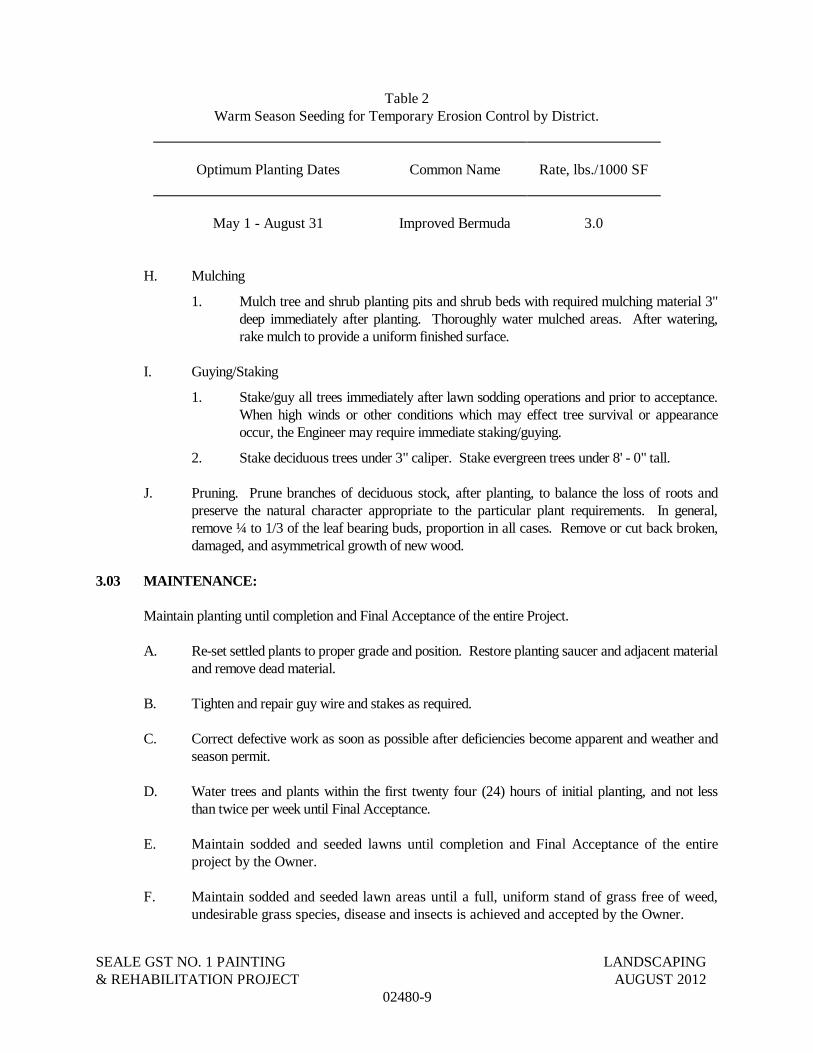
SEALE GST NO. 1 PAINTING LANDSCAPING& REHABILITATION PROJECT AUGUST 2012
02480-9
Table 2Warm Season Seeding for Temporary Erosion Control by District.
Optimum Planting Dates Common Name Rate, lbs./1000 SF
May 1 - August 31 Improved Bermuda 3.0
H. Mulching
1. Mulch tree and shrub planting pits and shrub beds with required mulching material 3"deep immediately after planting. Thoroughly water mulched areas. After watering,rake mulch to provide a uniform finished surface.
I. Guying/Staking
1. Stake/guy all trees immediately after lawn sodding operations and prior to acceptance.When high winds or other conditions which may effect tree survival or appearanceoccur, the Engineer may require immediate staking/guying.
2. Stake deciduous trees under 3" caliper. Stake evergreen trees under 8' - 0" tall.
J. Pruning. Prune branches of deciduous stock, after planting, to balance the loss of roots andpreserve the natural character appropriate to the particular plant requirements. In general,remove ¼ to 1/3 of the leaf bearing buds, proportion in all cases. Remove or cut back broken,damaged, and asymmetrical growth of new wood.
3.03 MAINTENANCE:
Maintain planting until completion and Final Acceptance of the entire Project.
A. Re-set settled plants to proper grade and position. Restore planting saucer and adjacent materialand remove dead material.
B. Tighten and repair guy wire and stakes as required.
C. Correct defective work as soon as possible after deficiencies become apparent and weather andseason permit.
D. Water trees and plants within the first twenty four (24) hours of initial planting, and not lessthan twice per week until Final Acceptance.
E. Maintain sodded and seeded lawns until completion and Final Acceptance of the entireproject by the Owner.
F. Maintain sodded and seeded lawn areas until a full, uniform stand of grass free of weed,undesirable grass species, disease and insects is achieved and accepted by the Owner.

SEALE GST NO. 1 PAINTING LANDSCAPING& REHABILITATION PROJECT AUGUST 2012
02480-10
3.04 ACCEPTANCE:
A. Field observation to determine recommendations on acceptance of planted areas will be made bythe Engineer, upon the Contractor's request. Provide notification at least ten (10) working daysbefore field observation date.
Planted areas will be acceptable to the Owner provided all requirements, including maintenance,have been complied with a plant materials are alive and in a healthy, vigorous condition.
B. Upon acceptance, the Owner will assume plant maintenance.
C. Field observations to determine recommendations on acceptance of sodded lawns will bemade by the Engineer upon Contractor's request. Provide notification at least ten (10)working days before requested field observation. Seeded and sodden areas will beacceptable to the Owner provided all requirements, including maintenance, have beencomplied with and a healthy, even colored viable lawn is established, free of weeds,undesirable grass species, disease and insects.
D. Upon acceptance, the Owner will assume lawn maintenance.
3.05 FINISHING:
A. Where applicable, the shoulders, slopes, and ditches shall be smoothed after planting hasbeen completed and shaped to conform to the cross-section previously provided andexisting at the time sodding operations were begun. Any excess dirt from the plantingoperations shall be spread uniformly over adjacent areas or disposed of as directed by theEngineer so that the completed surfaces will present a sightly appearance.
3.06 CLEANING:
A. Perform cleaning during installation of the work and upon completion of the work. Removefrom site all excess material, soil, debris and equipment. Repair damage resulting from plantingoperations.
END OF SECTION 02480

SEALE GST NO. 1 PAINTING TREE AND LANDSCAPE PROTECTION& REHABILITATION PROJECT AUGUST 2012
02481-1
SECTION 02481
TREE AND LANDSCAPE PROTECTION
PART 1 - GENERAL:
A. This item shall govern the placing of protection for trees and other landscape plantmaterial or natural areas to be protected during construction. No site preparation workshall begin in areas where tree preservation and treatment measures have not beencompleted and approved. Where removal of trees is indicated on the Contract Drawings,they shall be marked as directed by the engineer or designated representatives. Thisitem shall also govern the excavation, filling, trenching and boring around trees describedon the plans, and for furnishing all materials, water, labor, tools, equipment and suppliesrequired as specified by this item or as indicated on the plans.
B. Reference Standards:
1. City of San Antonio Tree Preservation ordinance # 85262 (latest edition).
PART 2 - MATERIALS:
A. LEVEL I FENCE PROTECTION:Fabric: Fabric (4 foot height or 1.2 m) shall consist of orange plastic fencing as shown onthe plans and shall be woven with 2-inch (50 mm) mesh openings such that in a verticaldimension of 23 inches (584 mm) along the diagonals of the openings there shall be at leastseven meshes.
1. Installation Posts: Installation posts shall be a minimum of 72 inches (1.5 m) longand steel “T” shaped with a minimum weight of 1.3 pounds per linear foot (6.3kg per meter).
2. Tie Wire: Wire for attaching the fabric to the t-posts shall be not less than No. 12gauge galvanized wire. Sufficient fastening material shall be furnished to providefor the securing of the fabric to the “T” line posts.
3. Used Materials: Previously-used materials, meeting the above requirements andwhen approved by the Engineer, may be used.
B. LEVEL IIA FENCE PROTECTION:
1. Materials same as Level I.
C. LEVEL IIB FENCE PROTECTION:
1. Sleeve: 2x4 lumber to a height of 4 feet above the root crown.
2. 2x4 shall be utilized as called for on plan.
3. Tie Wire: Wire for securing the 2x4s shall not be less than No. 12 gauge.
D. OTHER MATERIALS:

SEALE GST NO. 1 PAINTING TREE AND LANDSCAPE PROTECTION& REHABILITATION PROJECT AUGUST 2012
02481-2
1. Tree Dressing - Asphaltic Tree Wound Paint.
2. Dry Wells – Native Stone Wall or Concrete Segmental Retaining Wall System.
3. Paving – Permeable segmented pavers in conjunction with PVC pipe aerationsystem or concrete on gravel base with cored holes or suspended concrete slab.
4. Schedule 40 PVC Wheel and Spoke Venting System
5. Vertical Venting Systems-Schedule 40 PVC Pipe w/Fertilizer Basket and Cap orMetal Pipe w/Cap.
PART 3 - CONSTRUCTION METHODS:
3.01 LEVEL I FENCE PROTECTION:
A. All trees and shrubs in the proximity of the construction site shall be carefully checked forinjuries prior to beginning any development activity.
B. Protective fencing shall be erected at locations shown in the plans or as directed by theInspector and/or City Arborist or in accordance with the details shown on the plans at thedrip line of trees (Root Protection Zone, RPZ) and/or landscape plant material includingnatural areas. Fencing shall be maintained and repaired by the CONTRACTOR duringsite construction.
C. Protective fence locations in close proximity to street intersections or drives shall adhere tothe City of San Antonio’s site distance criteria.
D. The protective fencing shall be erected before site work commences and shall remain inplace during the entire construction phase. Access to fenced areas will be permitted onlywith the approval of the Engineer.
E. The installation posts will be placed every 6 feet (2 m) around the drip line or RPZ andembedded to 18 inches (457 mm) deep. Fabric attachment shall be attached to theinstallation posts by the use of sufficient wire ties to securely fasten the fabric to the “T”posts as to hold the fabric in a stable and upright position.
1. Do not clear, fill or grade in the RPZ of any tree.
2. Do not store, stockpile or dump any job material, soil or rubbish under the spreadof the tree branches.
3. Do not park or store any equipment or supplies under the spread of the treebranches.
4. Do not set up any construction operations under the spread of the tree branches.(E.g. pipe cutting and threading, mortar mixing, painting or lumber cutting)
5. Do not nail or attach temporary signs, meters, switches, wires, bracing or anyother item to the trees.
6. Do not permit runoff from waste materials including solvents, concrete washouts,asphalt tack coats (MC-30 oil), etc. to enter the RPZ. Barriers are to be provided

SEALE GST NO. 1 PAINTING TREE AND LANDSCAPE PROTECTION& REHABILITATION PROJECT AUGUST 2012
02481-3
to prevent such runoff substances from entering the RPZ whenever possible,including in an area where rain or surface water could carry such materials to theroot system of the tree.
F. The CONTRACTOR shall avoid cutting roots larger than one inch in diameter whenexcavation occurs near existing trees. Excavation in the vicinity of trees shall proceedwith caution. The CONTRACTOR shall contact the city inspector.
G. Remove all trees, shrubs or bushes to be cleared from protected root zone areas as directedby engineer by hand.
H. Trees damaged or lost due to CONTRACTOR’s negligence during construction shall bemitigated at the CONTRACTOR’s expense and to the engineer’s satisfaction.
I. Any tree removal shall be approved by the city arborist prior to its removal.
J. Cover exposed roots at the end of each day with soil, mulch or wet burlap.
K. In critical root zone areas that cannot be protected during construction and where heavytraffic is anticipated, cover those areas with eight (8) inches of organic mulch to minimizesoil compaction. This eight (8) inch depth of mulch shall be maintained throughoutconstruction.
L. Water all trees, most heavily impacted by construction activities, deeply once a weekduring periods of hot dry weather. Spray tree crowns with water periodically to reducedust accumulation on the leaves.
M. When installing concrete adjacent to the root zone of a tree, use a plastic vapor barrierbehind the concrete to prohibit leaching of lime into the soil. See related specifications.
N. When an excavation or embankment is placed within the drip line of any tree greater than(8) inches in diameter, a tree well shall be constructed to protect the tree as indicated, whenthe cut or fill exceeds (8) inches. See related specifications.
O. Where paving or filling is necessary within the drip line of any tree (8) inches or greater, apermeable pavement and aeration system must be installed as indicated. See relatedspecifications.
3.02 LEVEL II FENCE PROTECTION:
A. Fabric: Fabric (4 foot height or 1.2 m) shall consist of orange plastic fencing as shown onthe plans and shall be woven with 2-inch (50 mm) mesh openings such that in a verticaldimension of 23 inches (584 mm) along the diagonals of the openings there shall be at leastseven meshes.
B. Installation Posts: Installation posts shall be a minimum of 72 inches (1.5 m) long and steel“T” shaped with a minimum weight of 1.3 pounds per linear foot (6.3 kg per meter).

SEALE GST NO. 1 PAINTING TREE AND LANDSCAPE PROTECTION& REHABILITATION PROJECT AUGUST 2012
02481-4
C. Tie Wire: Wire for attaching the fabric to the t-posts shall be not less than No. 12 gaugegalvanized wire. Sufficient fastening material shall be furnished to provide for thesecuring of the fabric to the “T” line posts.
D. Used Materials: Previously-used materials, meeting the above requirements and whenapproved by the Engineer, may be used.
END OF SECTION

SEALE GST NO. 1 PAINTING FLEXIBLE BASE& REHABILITATION PROJECT AUGUST 2012
02500 - 1
SECTION 02500
FLEXIBLE BASE
PART 1 GENERAL
1.01 DESCRIPTION OF WORK:
A. This section shall govern for the construction of a base course for surfacing, pavement, orother base courses composed of crushed stone, and constructed as herein specified in oneor more courses in conformance with the typical sections , lines and grades as shown onthe plans.
B. The CONTRACTOR shall provide all necessary equipment, materials, labor, incidentalsand assistance required to complete the work in place as specified herein.
C. Flexible Base shall be provided and installed to the applicable provisions of the City ofSan Antonio Standard Specifications for Construction, Item 200 Flexible Base assupplemented and modified herein.
1.02 SUBMITTALS:
A. Provide submittals in accordance with Section 01300 – Submittals.
B. Product Data:
1. Materials list of items proposed to be provided under this Section.
2. Certificates, signed by the materials producer and the asphalt pavingsubcontractor, stating that materials meet or exceed the specified requirements.
1.03 QUALITY ASSURANCE:
A. Use adequate numbers of skilled workmen who are thoroughly trained andexperienced in the necessary crafts and who are completely familiar with thespecified requirements and the methods needed for proper performance of the work ofthis Section.
PART 2 PRODUCTS
2.01 MATERIALS
A. Furnish uncontaminated materials of uniform quality that meet the requirements of theplans and specifications. Notify the Engineer of the proposed material sources and ofchanges to material sources. The Engineer may sample and test project materials at anytime before compaction throughout the duration of the project to assure specificationcompliance. Use the TxDOT standard laboratory test procedure Tex-100-E for materialdefinitions.
B. Aggregate. Furnish aggregate of the type and grade shown on the plans and conformingto the requirements of Table 1. Each source must meet Table 1 requirements for liquidlimit, plasticity index, and wet ball mill for the grade specified. Do not use additives such

SEALE GST NO. 1 PAINTING FLEXIBLE BASE& REHABILITATION PROJECT AUGUST 2012
02500 - 2
as but not limited to lime, cement, or fly ash to modify aggregates to meet therequirements of Table 1, unless shown on the plans.
Table 1Aggregate Material Requirements
Property TestMethod1
Grade 1 Grade 2 Grade 3 Grade 4
Master gradation sievesize (% retained)
As shownon the plans
2-½ in. – 0 0
1-¾ in. 0 0–10 0–10 in. Tex-110-E 10–35 – –
in. 30–50 – –
No. 4 45–65 45–75 45–75
No. 40 70–85 60–85 50–85
Liquid limit, % max.2 Tex-104-E 35 40 40 As shownon the plans
Plasticity index, max.2 Tex-106-E 10 12 12 As shownon the plans
Plasticity index, min.2 As shown on the plans
Wet ball mill, % max.3 40 45 –As shown
on the plansWet ball mill, % max.increase passing the
No. 40 sieve3
Tex-116-E 20 20 –
1. TxDOT standard laboratory test procedures
2. Determine plastic index in accordance with Tex-107-E (linear shrinkage) when liquid limit isunattainable as defined in Tex-104-E.
3. ASTM C131 (Grad. A), Los Angeles Abrasion, can be used in lieu of the wet ball millprocedure. The maximum abrasion allowed to the crushed stone is forty (40) when subjected tothe Los Angeles Abrasion test.
1. Material Tolerances. The Engineer may accept material if no more than 1 of the5 most recent gradation tests has an individual sieve outside the specified limitsof the gradation.
When target grading is required by the plans, no single failing test may exceedthe master grading by more than 5 percentage points on sieves No. 4 and largeror 3 percentage points on sieves smaller than No. 4 sieve.
The Engineer may accept material if no more than 1 of the 5 most recentplasticity index tests is outside the specified limit. No single failing test mayexceed the allowable limit by more than 2 points.
2. Material Types. Do not use fillers or binders unless approved by the Engineer.Furnish the type specified on the plans in accordance with the following.
a. Type A. Crushed stone produced and graded from oversize quarriedaggregate that originates from a single, naturally occurring source. Do notuse gravel or multiple sources.
b. Type B. Not Used.

SEALE GST NO. 1 PAINTING FLEXIBLE BASE& REHABILITATION PROJECT AUGUST 2012
02500 - 3
c. Type C. Crushed gravel with a minimum of 60% of the particles retained ona No. 4 sieve with 2 or more crushed faces as determined by TxDOT’sstandard laboratory test procedure Tex-460-A, Part I. Blending of 2 or moresources is allowed.
d. Type D. Type A material or crushed concrete. Crushed concrete containinggravel will be considered Type D material. Crushed concrete must meet therequirements in Section 2.01 B.3.b, “Recycled Material (Including CrushedConcrete) Requirements,” and be managed in a way to provide for uniformquality. The Engineer may require separate dedicated stockpiles in order toverify compliance.
e. Type E. Not Used.
3. Recycled Material. Recycled asphalt pavement (RAP) and other recycledmaterials may be used when shown on the plans. Request approval to blend 2 ormore sources of recycled materials.
a. Limits on Percentage. When RAP is allowed, do not exceed 20% RAP byweight unless otherwise shown on the plans. The percentage limitations forother recycled materials will be as shown on the plans.
b. Recycled Material (Including Crushed Concrete) Requirements.i. Contractor Furnished Recycled Materials. When the Contractor
furnishes the recycled materials, including crushed concrete, the finalproduct will be subject to the requirements of Table 1 for the gradespecified. Certify compliance with TxDOT’s DMS-11000,“Evaluating and Using Nonhazardous Recyclable MaterialsGuidelines,” for Contractor furnished recycled materials. Inaddition, recycled materials must be free from reinforcing steel andother objectionable material and have at most 1.5% deleteriousmaterial when tested in accordance with TxDOT’s standardlaboratory test procedure Tex-413-A. For RAP, do not exceed amaximum percent loss from decantation of 5.0% when tested inaccordance with TxDOT’s standard laboratory test procedure Tex-406-A. Test RAP without removing the asphalt.
C. Water. Furnish water free of industrial wastes and other objectionable matter.
D. Material Sources. Only commercial sources may be used unless otherwise allowed bythe City and shown on the plans.
PART 3 EXECUTION
3.01 EQUIPMENT
A. Provide machinery, tools, and equipment necessary for proper execution of the work.Provide rollers in accordance with City of San Antonio Strand Specifications forConstruction, Item 210, “Rolling.” Provide proof rollers in accordance with TxDOT Item216, “Proof Rolling,” when required.
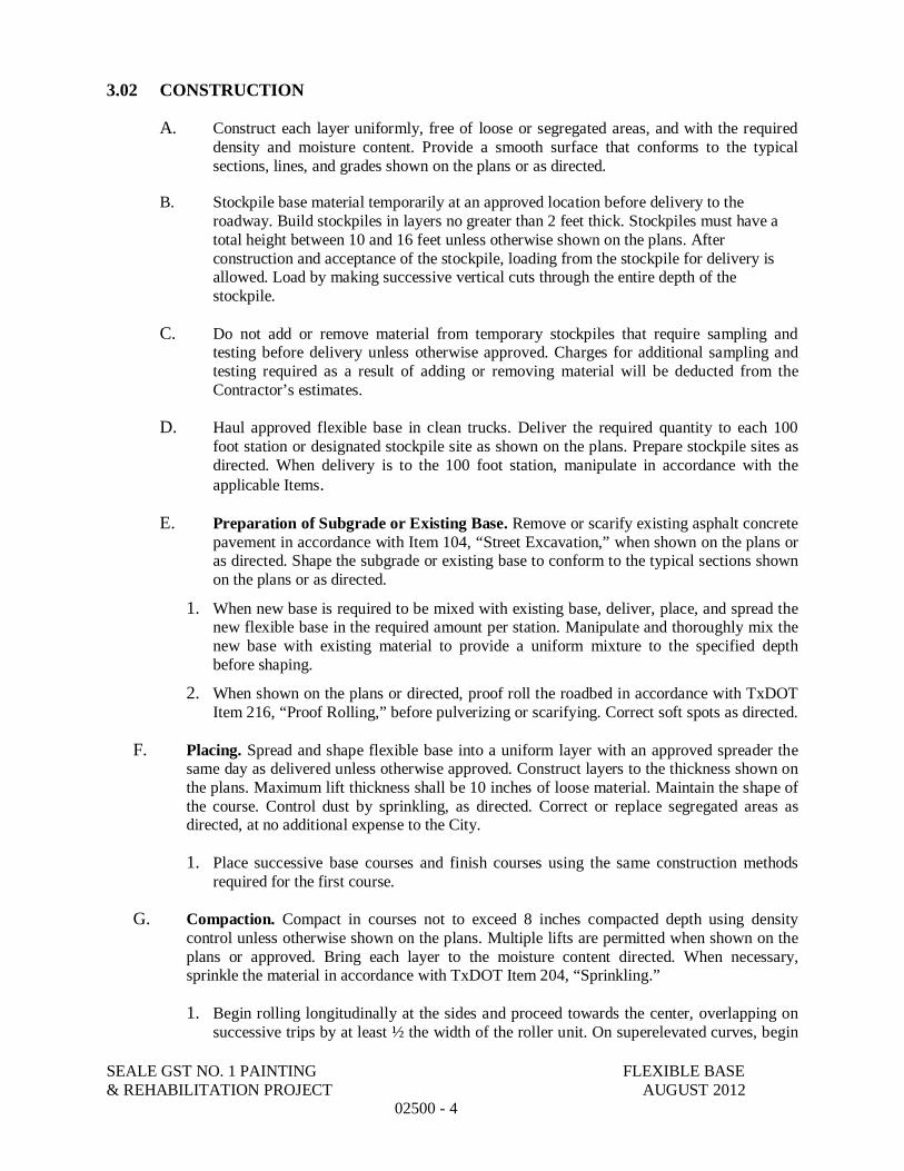
SEALE GST NO. 1 PAINTING FLEXIBLE BASE& REHABILITATION PROJECT AUGUST 2012
02500 - 4
3.02 CONSTRUCTION
A. Construct each layer uniformly, free of loose or segregated areas, and with the requireddensity and moisture content. Provide a smooth surface that conforms to the typicalsections, lines, and grades shown on the plans or as directed.
B. Stockpile base material temporarily at an approved location before delivery to theroadway. Build stockpiles in layers no greater than 2 feet thick. Stockpiles must have atotal height between 10 and 16 feet unless otherwise shown on the plans. Afterconstruction and acceptance of the stockpile, loading from the stockpile for delivery isallowed. Load by making successive vertical cuts through the entire depth of thestockpile.
C. Do not add or remove material from temporary stockpiles that require sampling andtesting before delivery unless otherwise approved. Charges for additional sampling andtesting required as a result of adding or removing material will be deducted from theContractor’s estimates.
D. Haul approved flexible base in clean trucks. Deliver the required quantity to each 100foot station or designated stockpile site as shown on the plans. Prepare stockpile sites asdirected. When delivery is to the 100 foot station, manipulate in accordance with theapplicable Items.
E. Preparation of Subgrade or Existing Base. Remove or scarify existing asphalt concretepavement in accordance with Item 104, “Street Excavation,” when shown on the plans oras directed. Shape the subgrade or existing base to conform to the typical sections shownon the plans or as directed.
1. When new base is required to be mixed with existing base, deliver, place, and spread thenew flexible base in the required amount per station. Manipulate and thoroughly mix thenew base with existing material to provide a uniform mixture to the specified depthbefore shaping.
2. When shown on the plans or directed, proof roll the roadbed in accordance with TxDOTItem 216, “Proof Rolling,” before pulverizing or scarifying. Correct soft spots as directed.
F. Placing. Spread and shape flexible base into a uniform layer with an approved spreader thesame day as delivered unless otherwise approved. Construct layers to the thickness shown onthe plans. Maximum lift thickness shall be 10 inches of loose material. Maintain the shape ofthe course. Control dust by sprinkling, as directed. Correct or replace segregated areas asdirected, at no additional expense to the City.
1. Place successive base courses and finish courses using the same construction methodsrequired for the first course.
G. Compaction. Compact in courses not to exceed 8 inches compacted depth using densitycontrol unless otherwise shown on the plans. Multiple lifts are permitted when shown on theplans or approved. Bring each layer to the moisture content directed. When necessary,sprinkle the material in accordance with TxDOT Item 204, “Sprinkling.”
1. Begin rolling longitudinally at the sides and proceed towards the center, overlapping onsuccessive trips by at least ½ the width of the roller unit. On superelevated curves, begin

SEALE GST NO. 1 PAINTING FLEXIBLE BASE& REHABILITATION PROJECT AUGUST 2012
02500 - 5
rolling at the low side and progress toward the high side. Offset alternate trips of theroller. Operate rollers at a speed between 2 and 6 mph as directed.
2. Rework, recompact, and refinish material that fails to meet or that loses requiredmoisture, density, stability, or finish before the next course is placed or the project isaccepted. Continue work until specification requirements are met. Perform the work at noadditional expense to the City.
3. Ordinary Compaction. Roll with approved compaction equipment as directed. Correctirregularities, depressions, and weak spots immediately by scarifying the areas affected,adding or removing approved material as required, reshaping, and recompacting.
4. Density Control. Compact to at least 95% of the maximum density determined byTxDOT’s standard laboratory test procedure Tex-113-E unless otherwise shown on theplans. Determine the moisture content of the material at the beginning and duringcompaction in accordance with TxDOT’s standard laboratory test procedure Tex-103-E.
a. Contractor to provide a third party materials testing laboratory, approved by theOwner, to determine roadway density of completed sections in accordance withTxDOT’s standard laboratory test procedure Tex-115-E. The Engineer mayaccept the section if no more than 1 of the 5 most recent density tests is below thespecified density and the failing test is no more than 3 pounds per cubic footbelow the specified density.
H. Finishing. After completing compaction, clip, skin, or tight-blade the surface with amaintainer or subgrade trimmer to a depth of approximately ¼ inch. Remove loosenedmaterial and dispose of it at an approved location. Seal the clipped surface immediately byrolling with a pneumatic tire roller until a smooth surface is attained. Add small increments ofwater as needed during rolling. Shape and maintain the course and surface in conformity withthe typical sections, lines, and grades as shown on the plans or as directed.
1. In areas where surfacing is to be placed, correct grade deviations greater than ¼ inch in16 feet measured longitudinally or greater than ¼ inch over the entire width of the cross-section. Correct by loosening, adding, or removing material. Reshape and recompact inaccordance with 3.02 G, “Compaction.”
I. Curing. Cure the finished section until the moisture content is at least 3 percentage pointsbelow and above optimum or as directed before applying the next successive course or primecoat.
END OF SECTION

This page intentionally left blank.

SEALE GST NO. 1 PAINTING PRIME COAT& REHABILITATION PROJECT AUGUST 2012
02502 - 1
SECTION 02502
PRIME COAT
PART 1 GENERAL
1.01 DESCRIPTION OF WORK:
A. This section shall govern for the application of asphaltic material on the completed basecourse and/or other areas in accordance with this specification and as directed by theEngineer. Apply blotter material as required.
B. The CONTRACTOR shall provide all necessary equipment, materials, labor, incidentalsand assistance required to complete the work in place as specified herein.
C. Prime Coat material shall be provided and installed to the applicable provisions of theCity of San Antonio Standard Specifications for Construction, Item 202 Prime Coat assupplemented and modified herein.
1.02 SUBMITTALS:
A. Provide submittals in accordance with Section 01300 – Submittals.
B. Product Data:
1. Materials list of items proposed to be provided under this Section.
2. Certificates, signed by the materials producer and the asphalt pavingsubcontractor, stating that materials meet or exceed the specified requirements.
1.03 QUALITY ASSURANCE:
A. Use adequate numbers of skilled workmen who are thoroughly trained andexperienced in the necessary crafts and who are completely familiar with thespecified requirements and the methods needed for proper performance of the work ofthis Section.
PART 2 PRODUCTS
2.01 MATERIALS
A. Bituminous. Unless the type and grade are shown on the plans, utilize an MC-30 orAE-P asphalt cement in accordance with Item 300, “Asphalts, Oils, and Emulsions” ofthe Standard Specifications of the Texas Department of Transportation for prime coat.Where Emulsified Asphalts are used, the amount of emulsified asphalt as a percentage byvolume of the total mixture shall be within the limits shown on the plans, or shall be of apercentage as directed by the Engineer.
B. Blotter. Unless otherwise shown on the plans or approved, use either base coursesweepings obtained from cleaning the base or sand as blotter materials.

SEALE GST NO. 1 PAINTING PRIME COAT& REHABILITATION PROJECT AUGUST 2012
02502 - 2
PART 3 EXECUTION
3.01 EQUIPMENT
Provide applicable equipment in accordance with this specification or as specified on the plans.
A. Distributor. Furnish a distributor that will apply the asphalt material uniformly at thespecified rate or as directed.
1. Transverse Variance Rate. When a transverse variance rate is shown on the plans,confirm that the nozzles outside the wheel paths will output a predeterminedpercentage more of asphalt material by volume than the nozzles over the wheel paths.
2. Calibration
a. Transverse Distribution. Furnish a distributor test report, no more than 1year old, documenting that the variation in output for individual nozzles ofthe same size does not exceed 10% when tested at the greatest shot widthin accordance with Tex-922K, “Calibrating Asphalt DistributionEquipment,” Part III.
b. Include the following documentation on the test report:i. the serial number of the distributor,ii. a method that identifies the actual nozzle set used in the test, andiii. the fan width of the nozzle set at a 12 inch bar height.
c. When a transverse variance rate is required, perform the test using the typeand grade of asphalt material to be used on the project. The Engineer mayverify the transverse rate and distribution at any time. If verification doesnot meet the requirements, correct deficiencies and furnish a new testreport.
B. Tank Volume. Furnish a volumetric calibration and strap stick for the distributor tankin accordance with Tex-922-K, “Calibrating Asphalt Distribution Equipment,” Part I.Calibrate the distributor within the previous 3 years of the date first used on the project.The Engineer may verify calibration accuracy in accordance with Tex-922-K,“Calibrating Asphalt Distribution Equipment,” Part II.
C. Computerized Distributor. When paying for asphalt material by weight, theEngineer may allow use of the computerized distributor display to verify applicationrates. Verify application rate accuracy at a frequency acceptable to the Engineer.
D. Broom. Furnish rotary, self-propelled brooms.
E. Rollers. Rollers provided shall meet the requirements for their type as shown in Item210, “Rollers.”
F. Asphalt Storage and Handling Equipment. When the plans or the Engineer allowsstorage tanks, furnish a thermometer in each tank to indicate the asphalt temperaturecontinuously.
G. Digital Measuring Instrument. Furnish a vehicle with a calibrated digital-measuringinstrument accurate to ±6 ft. per mile.

SEALE GST NO. 1 PAINTING PRIME COAT& REHABILITATION PROJECT AUGUST 2012
02502 - 3
3.02 CONSTRUCTION
A. General. Apply the mixture when the air temperature is 60ºF and above, or above 50ºFand rising. Measure the air temperature in the shade away from artificial heat. TheEngineer will determine when weather conditions are suitable for application.
Do not permit traffic, hauling, or placement of subsequent courses over freshlyconstructed prime coats. Maintain the primed surface until placement of subsequentcourses or acceptance of the work.
B. Surface Preparation. Prepare the surface by sweeping or other approved methods.When directed, before applying bituminous material, lightly sprinkle the surface withwater to control dust and ensure absorption.
C. Application.1. Bituminous. Application temperatures shall be within the limits
recommended in Item 300, “Asphalts, Oils, and Emulsions.” Apply materialwithin 15º F of the selected temperature.
2. Unless otherwise shown on the plans, prime coat shall be applied at a rate notto exceed 0.20 gallon per square yard of surface. The prime coat shall be appliedevenly and smoothly, under a pressure necessary for proper distribution.
3. When emulsified asphalts are used as prime coat, agitate the water and emulsifiedasphalt to produce a uniform blend. Evenly distribute, at the rate specified, tolocations shown on the plans or as directed. Regulate the percentage of emulsifiedasphalt in the mixture and distribute successive applications to achieve the specifiedrate, if necessary.
4. During the application of prime coat, care shall be taken to prevent splattering ofadjacent pavement, curb and gutters or structures. When directed, roll the freshlyapplied prime coat with a pneumatic-tire roller to ensure penetration.
5. Blotter. Spread blotter material before allowing traffic to use a primed surface. When“Prime Coat and Blotter” is shown on the plans, apply blotter material to primedsurface at the rate shown in the plans or as directed. When “Prime Coat” is shown onthe plans, apply blotter to spot locations or as directed to accommodate trafficmovement through the work area. Remove blotter material before placing the surface.Dispose of blotter material according to applicable state and federal requirements.
END OF SECTION

This page intentionally left blank.

SEALE GST NO. 1 PAINTING TACK COAT& REHABILITATION PROJECT AUGUST 2012
02503 - 1
SECTION 02503
TACK COAT
PART 1 GENERAL
1.01 DESCRIPTION OF WORK:
A. This section shall govern for the application of asphaltic material on the completed basecourse after the prime coat has sufficiently cured, existing pavement, bituminoussurfaces, or other areas in accordance with this specification and as directed by theEngineer.
B. The CONTRACTOR shall provide all necessary equipment, materials, labor, incidentalsand assistance required to complete the work in place as specified herein.
C. Tack Coat material shall be provided and installed to the applicable provisions of the Cityof San Antonio Standard Specifications for Construction, Item 203 Tack Coat assupplemented and modified herein.
1.02 SUBMITTALS:
A. Provide submittals in accordance with Section 01300 – Submittals.
B. Product Data:
1. Materials list of items proposed to be provided under this Section.
2. Certificates, signed by the materials producer and the asphalt pavingsubcontractor, stating that materials meet or exceed the specified requirements.
1.03 QUALITY ASSURANCE:
A. Use adequate numbers of skilled workmen who are thoroughly trained andexperienced in the necessary crafts and who are completely familiar with thespecified requirements and the methods needed for proper performance of the work ofthis Section.
PART 2 PRODUCTS
2.01 MATERIALS
A. The asphaltic material used for Tack Coat shall meet the requirements for “AsphaltCement”, “Cut-Back Asphalt” or “Emulsified Asphalt” in Item No. 300, “Asphalts, Oilsand Emulsions” of the Texas Department of Transportation Standard Specifications. Theasphaltic material used for Tack Coat shall be the type or grade shown in the referringspecification, or on the plans, or as directed/approved by the Engineer.

SEALE GST NO. 1 PAINTING TACK COAT& REHABILITATION PROJECT AUGUST 2012
02503 - 2
PART 3 EXECUTION
3.01 EQUIPMENT
A. Provide equipment that conforms to the requirements of Section 02020 - Prime Coat,paragraph 3.01 Equipment.
3.02 CONSTRUCTION
A. Before the tack coat is applied, the surface shall be cleaned thoroughly with a vacuumsweeper to the satisfaction of the Engineer. The asphaltic material shall be applied on theclean surface by an approved type of self-propelled pressure distributor evenly andsmoothly under a pressure necessary for proper distribution.
B. The tack coat shall be applied at the rate specified by the referring specification or on theplans. Unless otherwise stated or allowed by the Engineer the application rate shall notexceed 0.10 gallon per square yard of surface.
C. Where the pavement mixture will adhere to the surface on which it is to be placedwithout the use of a tack coat, the tack coat may be eliminated by the Engineer. Allcontact surfaces of curbs and structures and all joints shall be painted with a thin uniformcoat of the asphaltic material used for tack coat. During the application of tack coat, careshall be taken to prevent splattering of adjacent pavement, curb and gutters or structures.
END OF SECTION

SEALE GST NO. 1 PAINTING ASPHALTIC CONCRETE PAVING& REHABILITATION PROJECT AUGUST 2012
02513 - 1
SECTION 02513
ASPHALTIC CONCRETE PAVING
PART 1 GENERAL
1.01 SUMMARY
A. Provide asphaltic concrete paving, to be composed of a compacted mixture of mineral aggregateand asphaltic material. The pavement shall be constructed on the newly constructed subgrade andbase course where shown on the Contract Drawings, as specified herein, and as needed for acomplete and proper installation.
B. Related work:
1. Documents affecting work of this Section include, but are not necessarily limited to,General Conditions, Supplementary Conditions, and Sections in Division 1 of theseSpecifications.
1.02 SUBMITTALS
A. Comply with pertinent provisions of Section 01300 - Submittals.
B. Product data: Within 35 calendar days after the CONTRACTOR has received the Owner'sNotice to Proceed, submit:
1. Materials list of items proposed to be provided under this Section;
2. Certificates, signed by the materials producer and the asphalt paving subcontractor,stating that materials meet or exceed the specified requirements.
1.03 QUALITY ASSURANCE
A. Use adequate numbers of skilled workmen who are thoroughly trained and experienced inthe necessary crafts and who are completely familiar with the specified requirements andthe methods needed for proper performance of the work of this Section.
1.04 DELIVERY, STORAGE, AND HANDLING
A. Comply with pertinent provisions of Section 01600 – Materials and Equipment.
PART 2 PRODUCTS
2.01 HOT MIX ASPHALTIC CONCRETE PAVEMENT (HMAC)
A. The asphaltic concrete shall be plant mixed, hot laid Type D (Fine Graded or Surface Course)meeting the requirements of Item 340, “Dense-Graded Hot-Mix Asphalt (Method)” of the TexasDepartment of Transportation Standard Specification for Construction and Maintenance ofHighways, Streets, and Bridges.
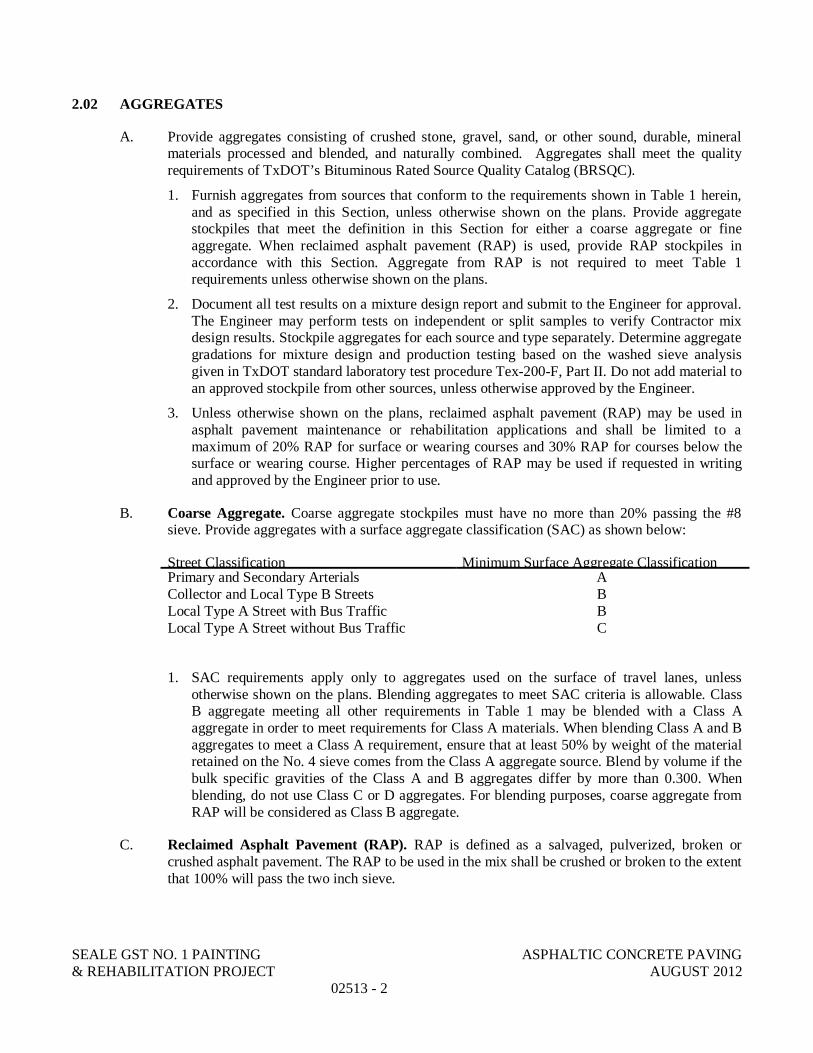
SEALE GST NO. 1 PAINTING ASPHALTIC CONCRETE PAVING& REHABILITATION PROJECT AUGUST 2012
02513 - 2
2.02 AGGREGATES
A. Provide aggregates consisting of crushed stone, gravel, sand, or other sound, durable, mineralmaterials processed and blended, and naturally combined. Aggregates shall meet the qualityrequirements of TxDOT’s Bituminous Rated Source Quality Catalog (BRSQC).
1. Furnish aggregates from sources that conform to the requirements shown in Table 1 herein,and as specified in this Section, unless otherwise shown on the plans. Provide aggregatestockpiles that meet the definition in this Section for either a coarse aggregate or fineaggregate. When reclaimed asphalt pavement (RAP) is used, provide RAP stockpiles inaccordance with this Section. Aggregate from RAP is not required to meet Table 1requirements unless otherwise shown on the plans.
2. Document all test results on a mixture design report and submit to the Engineer for approval.The Engineer may perform tests on independent or split samples to verify Contractor mixdesign results. Stockpile aggregates for each source and type separately. Determine aggregategradations for mixture design and production testing based on the washed sieve analysisgiven in TxDOT standard laboratory test procedure Tex-200-F, Part II. Do not add material toan approved stockpile from other sources, unless otherwise approved by the Engineer.
3. Unless otherwise shown on the plans, reclaimed asphalt pavement (RAP) may be used inasphalt pavement maintenance or rehabilitation applications and shall be limited to amaximum of 20% RAP for surface or wearing courses and 30% RAP for courses below thesurface or wearing course. Higher percentages of RAP may be used if requested in writingand approved by the Engineer prior to use.
B. Coarse Aggregate. Coarse aggregate stockpiles must have no more than 20% passing the #8sieve. Provide aggregates with a surface aggregate classification (SAC) as shown below:
Street Classification Minimum Surface Aggregate ClassificationPrimary and Secondary Arterials ACollector and Local Type B Streets BLocal Type A Street with Bus Traffic BLocal Type A Street without Bus Traffic C
1. SAC requirements apply only to aggregates used on the surface of travel lanes, unlessotherwise shown on the plans. Blending aggregates to meet SAC criteria is allowable. ClassB aggregate meeting all other requirements in Table 1 may be blended with a Class Aaggregate in order to meet requirements for Class A materials. When blending Class A and Baggregates to meet a Class A requirement, ensure that at least 50% by weight of the materialretained on the No. 4 sieve comes from the Class A aggregate source. Blend by volume if thebulk specific gravities of the Class A and B aggregates differ by more than 0.300. Whenblending, do not use Class C or D aggregates. For blending purposes, coarse aggregate fromRAP will be considered as Class B aggregate.
C. Reclaimed Asphalt Pavement (RAP). RAP is defined as a salvaged, pulverized, broken orcrushed asphalt pavement. The RAP to be used in the mix shall be crushed or broken to the extentthat 100% will pass the two inch sieve.

SEALE GST NO. 1 PAINTING ASPHALTIC CONCRETE PAVING& REHABILITATION PROJECT AUGUST 2012
02513 - 3
1. The stockpiled RAP shall not be contaminated by dirt or other objectionable materials.Unless otherwise shown on the plans, stockpiled, crushed RAP shall have a decantation of5% or less and a plasticity index of eight (8) or less, when tested in accordance with TxDOTstandard laboratory test procedures Tex-406-A, Part I, and Tex-106-E, respectively. Thisrequirement applies to stockpiles from which the asphalt has not been removed by extraction.When RAP is used, determine asphalt content and gradation for mixture design purposes.
D. Fine Aggregate. Fine aggregates may consist of manufactured sands, screenings and field sands.Supply fine aggregates that are free from organic impurities. Field sands and other uncrushedaggregates shall be limited to 15% of the total aggregate.
1. If 10% or more of the fine aggregate stockpile is retained on the No. 4 sieve, test the stockpileand verify that it meets the requirements in Table 1 for coarse aggregate angularity (TxDOTstandard laboratory test procedure Tex-460-A) and flat and elongated particles (TxDOTstandard laboratory test procedure Tex-280-F).
E. Asphalt Binder. Unless shown on the plans, provide the type and grade of performance-gradedasphalt binder in accordance with TxDOT Item 300.2.J. “Performance-Graded Binders” and asspecified below:
Street Classification
Minimum PG Asphalt Cement Grade
SurfaceCourses
Binder &Level UpCourses
BaseCourses
Primary and Secondary Arterials PG 76-22PG 70-22
PG 64-22Collector and Local Type B StreetsLocal Type A Street With Bus Traffic PG 70-22
PG 64-22Local Type A Street Without Bus Traffic
F. Mineral Filler. Mineral filler consists of finely divided mineral matter such as agricultural lime,crusher fines, hydrated lime, cement, or fly ash. Mineral filler is allowed unless otherwise shownon the plans. Do not use more than 2% hydrated lime or cement, unless otherwise shown on theplans. The plans may require or disallow specific mineral fillers. When used, provide mineralfiller that:
1. is sufficiently dry, free-flowing, and free from clumps and foreign matter;
2. does not exceed 3% linear shrinkage when tested in accordance with Tex-107-E; and
3. meets the gradation requirements of Table 3 herein.
G. Baghouse Fines. Fines collected by the baghouse or other dust collecting equipment may bereintroduced into the mixing drum.
H. Tack Coat. Unless otherwise shown on the plans or approved, furnish CSS-1H, SS-1H, or a PGbinder with a minimum high-temperature grade of PG 58 for tack coat binder and in accordance withSpecification 02530 - Tack Coat. Do not dilute emulsified asphalts at the terminal, in the field, or atany other location before use.

SEALE GST NO. 1 PAINTING ASPHALTIC CONCRETE PAVING& REHABILITATION PROJECT AUGUST 2012
02513 - 4
I. Additives. When shown on the plans, use the type and rate of additive specified. Other additives thatfacilitate mixing or improve the quality of the mixture may be allowed when approved. If lime or aliquid antistripping agent is used, add in accordance with TxDOT Item 301, “Asphalt AntistrippingAgents.” Do not add lime directly into the mixing drum of any plant where lime is removed throughthe exhaust stream, unless the plant has a baghouse or dust collection system that reintroduces thelime back into the drum.
Table 1Aggregate Quality Requirements
Property
TxDOT StandardLaboratory Test
Procedure
SurfaceCourses
Binder, LevelUp, & Base
CoursesCoarse Aggregate
Deleterious Material, %, max Tex-217-F, Part I 1.0 1.5Decantation, %, max Tex-217-F, Part II 1.5 1.5Micro-Deval Abrasion, %, max Tex-461-A Screening Only Screening OnlyLos Angeles Abrasion, %, max Tex-410-A 35 40Magnesium Sulfate Soundness, 5 cycles, %, max Tex-411-A 25 30Coarse Aggregate Angularity, 2 crushed faces, %, min Tex-460-A, Part I 951 851
Flat and Elongated Particles @ 5:1, %, max Tex-280-F 10 10Fine Aggregate
Linear Shrinkage, %, max Tex-107-E 3 3Combined Aggregate2
Sand Equivalent, %, min Tex-203-F 45 45Note 1: Applies to Gravel OnlyNote 2: Aggregate without mineral filler, RAP, or additives combined as used in the job-mixed formula (JMF)
Table 2Gradation Requirements for Fine Aggregates
Sieve Size, in % Passing by Weight or Volume
3/8 100#8 70 – 100
#200 0 – 30
Table 3Gradation Requirements for Mineral Filler
Sieve Size, in % Passing by Weight or Volume
#8 100#200 55 – 100

SEALE GST NO. 1 PAINTING ASPHALTIC CONCRETE PAVING& REHABILITATION PROJECT AUGUST 2012
02513 - 5
2.03 EQUIPMENT
A. All equipment for the handling of all materials, mixing, placing and compacting of the mixture shallbe maintained in good repair and operating condition and subject to the approval of the Engineer. Anyequipment found to be defective and potentially having a negative effect on the quality of the pavingmixture or ride quality will not be allowed.
B. Spreading and Finishing Machine. The spreading and finishing machine shall be approved by theEngineer and shall meet the requirements indicated below.
1. Screed Unit. The spreading and finishing machine shall be equipped with a heatedcompacting screed. It shall produce a finished surface meeting the requirements of the typicalcross sections and the surface test.
2. Extensions added to the screed shall be provided with the same compacting action andheating capability as the main screed unit, except for use on variable depth tapered areasand/or as approved by the Engineer.
3. The spreading and finishing machine shall be equipped with an approved automatic duallongitudinal screed control system and automatic transverse screed control system. Thelongitudinal controls shall be capable of operating from any longitudinal grade referenceincluding a stringline, ski, mobile stringline, or matching shoe.
4. The Contractor shall furnish all equipment required for grade reference. It shall be maintainedin good operating condition by personnel trained in the use of this type of equipment.
5. The grade reference used by the Contractor may be of any type approved by the Engineer.The contractor shall set the grade reference to have sufficient support so that the maximumdeflection shall not exceed 1/16 inch between supports.
C. Tractor Unit. The tractor unit shall be equipped with a hydraulic hitch sufficient in design andcapacity to maintain contact between the rear wheels of the hauling equipment and the pusher rollersof the finishing machine while the mixture is being unloaded.
1. No portion of the weight of hauling equipment, other than the connection, shall be supportedby the asphalt paver. No vibrations or other motions of the loading equipment, which couldhave a detrimental effect on the riding quality of the completed pavement, shall betransmitted to the paver.
2. The use of any vehicle which requires dumping directly into the finishing machine and whichthe finishing machine cannot push or propel to obtain the desired lines and grades withoutresorting to hand finishing will not be allowed.
D. Material Transfer Equipment. Equipment to transfer mixture from the hauling units or the roadbedto the spreading and finishing machine will be allowed unless otherwise shown on the plans. Aspecific type of material transfer equipment shall be required when shown on the plans.
E. Motor Grader. The motor grader, when used, shall meet the requirements as shown in the City ofSan Antonio Standard Specifications for Construction, Item 220, “Blading.”
F. Rollers. Rollers provided shall meet the requirements for their type as shown in the City of SanAntonio Standard Specifications for Construction, Item 210, “Rolling.”
SEALE GST NO. 1 PAINTING ASPHALTIC CONCRETE PAVING& REHABILITATION PROJECT AUGUST 2012
02513 - 6
PART 3 EXECUTION
3.01 CONSTRUCTION
A. It shall be the responsibility of the Contractor to design, produce, transport, place and compact thespecified paving mixture in accordance with the requirements herein. The Engineer will performverification testing as needed. Provide quality control (QC) testing as needed to meet therequirements of this Item. Provide a certified Level I-A specialist at the plant during productionhours. Provide a certified Level I-B specialist to conduct placement tests.
3.02 QUALITY CONTROL PLAN (QCP)
A. Unless otherwise shown on the plans, develop and follow a QCP. Obtain approval from theEngineer for changes to the QCP made during the project. The Engineer may suspend operationsif the Contractor fails to comply with the QCP.
B. Submit a written QCP to the Engineer and receive the Engineer’s approval of the QCP beforebeginning production. Include the following items in the QCP.
1. Project Personnel. Provide:a. a list of individuals that will conduct tests as well their associated certifications (i.e.
Level IA, IB, and II certifications), including when certifications will expire for eachindividual; and
b. a list of individuals responsible for QC with authority to take corrective action andthe contact information for each individual listed.
2. Material Delivery and Storage. Provide:a. the sequence of material processing, delivery, and minimum quantities to assure
continuous plant operations;b. aggregate stockpiling procedures to avoid contamination and segregation;c. frequency, type, and timing of aggregate stockpile testing to assure conformance of
material requirements before mixture production; andd. procedure for monitoring the quality and variability of asphalt binder.
3. Production. Detail:a. loader operation procedures to avoid contamination in cold bins;b. procedures for calibrating and controlling cold feeds;c. procedures to eliminate debris or oversized material;d. procedures for adding and verifying rates of each applicable mixture component
(e.g., aggregate, asphalt binder, RAP, lime, liquid antistrip);e. procedures for reporting job control and acceptance test results; andf. procedures to avoid segregation and drain-down in the silo.
4. Loading and Transporting. Provide:a. the type and application method for release agents; andb. truck loading procedures to avoid segregation.
5. Placement and Compaction. Provide:a. the proposed agenda for mandatory pre-paving meeting including date and location;b. the type and application method for release agents in the paver and on rollers,
shovels, lutes, and other utensils;

SEALE GST NO. 1 PAINTING ASPHALTIC CONCRETE PAVING& REHABILITATION PROJECT AUGUST 2012
02513 - 7
c. procedures for the transfer of mixture into the paver while avoiding segregation andpreventing material spillage;
d. the process to balance production, delivery, paving, and compaction to achievecontinuous placement operations;
e. the paver operations (e.g., operation of wings, height of mixture in auger chamber) toavoid physical and thermal segregation and other surface irregularities; and
f. procedures to construct quality longitudinal and transverse joints.
3.03 MIXTURE DESISGN
A. Use a Level II specialist certified by a TxDOT-approved hot-mix asphalt certification program todevelop the mixture design. Have the Level II specialist sign the design documents. Unlessotherwise shown on the plans, use the typical weight design example given in TxDOT standardlaboratory test procedure Tex-204-F, Part I or Part III, to design a mixture meeting therequirements listed in Tables 1 through 5. At the request of the Engineer, furnish representativesamples of all materials used in the mixture design for verification. If the design cannot beverified by the Engineer, furnish another mixture design.
B. The Contractor may submit a new mixture design at anytime during the project. The Engineerwill approve all mixture designs before the Contractor can begin production.
C. Provide the Engineer with a mixture design report that includes the following items:
1. the combined aggregate gradation, source, specific gravity, and percent of each material used;
2. results of all applicable tests;
3. the mixing and molding temperatures;
4. all applicable correlation and correction factors;
5. the signature of the Level II person or persons who performed the design;
6. the date the mixture design was performed; and
7. a unique identification number for the mixture design.
D. The Hamburg Wheel Test is not required, unless otherwise shown on the plans. When requiredthrough plan note, the minimum number of passes shown in Table 6 shall be met, unlessotherwise approved by the Engineer. The contractor will be responsible for submitting the resultsof the Hamburg Wheel test to the Engineer with the other mixture design data. Use an approvedlaboratory to perform the Hamburg Wheel test. The TxDOT Construction Division maintains alist of approved laboratories that may be referenced. Hamburg Wheel Testing will not beperformed or required for any Type “F” mixtures.
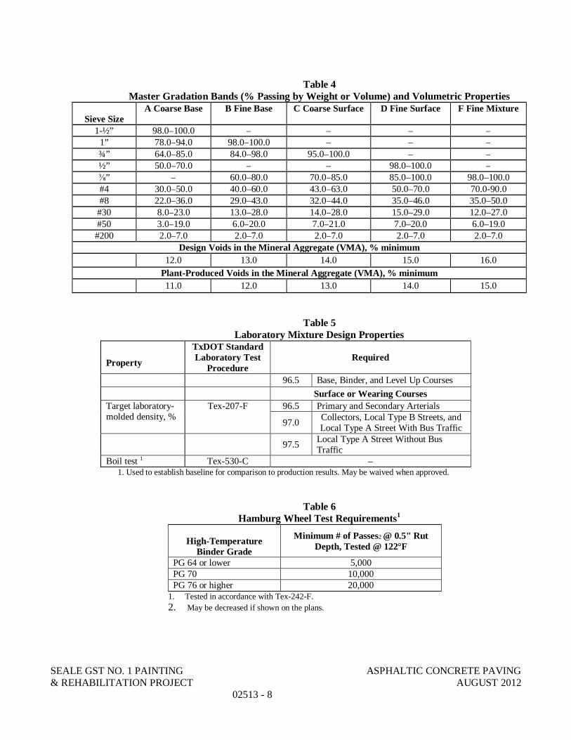
SEALE GST NO. 1 PAINTING ASPHALTIC CONCRETE PAVING& REHABILITATION PROJECT AUGUST 2012
02513 - 8
Table 4Master Gradation Bands (% Passing by Weight or Volume) and Volumetric Properties
Sieve SizeA Coarse Base B Fine Base C Coarse Surface D Fine Surface F Fine Mixture
1-½” 98.0–100.0 – – – –1” 78.0–94.0 98.0–100.0 – – –¾” 64.0–85.0 84.0–98.0 95.0–100.0 – –½” 50.0–70.0 – – 98.0–100.0 –
” – 60.0–80.0 70.0–85.0 85.0–100.0 98.0–100.0#4 30.0–50.0 40.0–60.0 43.0–63.0 50.0–70.0 70.0-90.0#8 22.0–36.0 29.0–43.0 32.0–44.0 35.0–46.0 35.0–50.0
#30 8.0–23.0 13.0–28.0 14.0–28.0 15.0–29.0 12.0–27.0#50 3.0–19.0 6.0–20.0 7.0–21.0 7.0–20.0 6.0–19.0#200 2.0–7.0 2.0–7.0 2.0–7.0 2.0–7.0 2.0–7.0
Design Voids in the Mineral Aggregate (VMA), % minimum12.0 13.0 14.0 15.0 16.0
Plant-Produced Voids in the Mineral Aggregate (VMA), % minimum11.0 12.0 13.0 14.0 15.0
Table 5Laboratory Mixture Design Properties
Property
TxDOT StandardLaboratory Test
ProcedureRequired
96.5 Base, Binder, and Level Up CoursesSurface or Wearing Courses
Target laboratory-molded density, %
Tex-207-F 96.5 Primary and Secondary Arterials
97.0 Collectors, Local Type B Streets, andLocal Type A Street With Bus Traffic
97.5 Local Type A Street Without BusTraffic
Boil test 1 Tex-530-C –1. Used to establish baseline for comparison to production results. May be waived when approved.
Table 6Hamburg Wheel Test Requirements1
High-TemperatureBinder Grade
Minimum # of Passes2 @ 0.5" RutDepth, Tested @ 122°F
PG 64 or lower 5,000PG 70 10,000PG 76 or higher 20,000
1. Tested in accordance with Tex-242-F.2. May be decreased if shown on the plans.

SEALE GST NO. 1 PAINTING ASPHALTIC CONCRETE PAVING& REHABILITATION PROJECT AUGUST 2012
02513 - 9
3.04 JOB-MIX FORMULA
A. The laboratory mixture design shall be submitted to the Engineer for approval prior to productionand placement. The submittal shall provide the laboratory designed mixture target properties anddata that demonstrate the contractor’s ability to produce the mixture within the tolerancesspecified in Table 7 herein either through a trial batch or by submittal of previous production datafrom a City or TxDOT project.
B. Once approved, the contractor may begin production and placement of the approved JMF. Resultsfrom Lot 1 of the JMF may be used to modify the optimum mixture properties as long as thetested properties are within the tolerances specified in Table 7 herein. Further adjustments to theJMF may be allowed by the Engineer during production and placement, if warranted. JMFadjustment requests must be made in writing to the Engineer and the mixture must conform to themaster gradation limits for the mixture type and be within the operational limits of Table 7 notedabove for the initial JMF approved by the Engineer.
Table 7Operational Tolerances
Description Test Method Allowable Difference fromCurrent JMF Target
Individual % Retained for #8 Sieve or Larger ±5.0 1
Individual % Retained for Sieves Smaller than#8 and Larger than #200
Tex-200-F orTex-236-F ±3.0 1
% Passing the #200 Sieve ±2.0 1
Asphalt Content, % Tex-236-F ±0.3 2
Laboratory-Molded Density, % Tex-207-F ±1.0VMA, % minimum Note 3
Note 1: When within these tolerances, mixture production gradations may fall outside the master grading limits; however, the% passing the #200 sieve will be considered out of tolerance when outside the master grading limits.Note 2: Tolerance between Laboratory Mix and Plant Trial Batch may exceed ±0.3.Note 3: Test and verify that Table 4 requirements are met.
3.05 PRODUCTION
A. Do not heat the asphalt binder above the temperatures specified in TxDOT Item 300, “Asphalts,Oils, and Emulsions,” or outside the manufacturer’s recommended values. Do not store anasphaltic mixture for a period long enough to affect the quality of the mixture, nor in any caselonger than 12 hr.
B. Notify the Engineer of the target discharge temperature and produce the mixture within 25°F ofthe target. Monitor the temperature of the material in the truck before shipping to ensure that itdoes not exceed 350°F. The Engineer will not pay for, or allow placement of, any mixtureproduced at more than 350°F. Control the mixing time and temperature so that moisture isremoved from the mixture before discharging from the plant. If requested, determine the moisturecontent by oven-drying in accordance with TxDOT standard laboratory test procedure Tex-212-F,Part II, and verify that the mixture contains no more than 0.2% of moisture by weight. Obtain thesample immediately after discharging the mixture into the truck, and perform the test promptly.
SEALE GST NO. 1 PAINTING ASPHALTIC CONCRETE PAVING& REHABILITATION PROJECT AUGUST 2012
02513 - 10
C. Perform a new trial batch when the plant or plant location is changed. The Engineer may suspendproduction for noncompliance with this Item. Take corrective action and obtain approval toproceed after any production suspension for noncompliance.
3.06 TACK COAT
A. The surface upon which the tack coat is to be placed shall be cleaned thoroughly to thesatisfaction of the Inspector. The surface shall be given a uniform application of tack coat usingasphaltic materials of this specification. Unless otherwise shown on the plans, tack coat shall beapplied with an approved sprayer at a rate directed by the Engineer between 0.04 and 0.10 gallonresidual asphalt per square yard of surface.
3.07 TRANSPORTING ASPHALTIC CONCRETE
A. The asphaltic mixture shall be hauled to the work site in vehicles previously cleaned of all foreignmaterial and with beds that do not discharge or lose materials during the haul. Trucks that do notmeet the satisfaction of the Engineer or Inspector will not be allowed to deliver materials to Cityprojects. The dispatching of the vehicles shall be arranged so that all material is delivered, placed,and rolled during daylight hours unless otherwise shown on the plans. In cool weather, or for longhauls, covering and insulating of the truck bodies may be required. If necessary, to prevent themixture from adhering to the inside of the truck body, the inside of the truck may be given a lightcoating of release agent satisfactory to the Engineer.
3.08 PLACEMENT
A. Weather Conditions. Place mixture, when placed with a spreading and finishing machine, or thetack coat when the roadway surface temperature is 60°F or higher unless otherwise approved.Measure the roadway surface temperature with a handheld infrared thermometer. Place mixturesonly when weather conditions and moisture conditions of the roadway surface are suitable in theopinion of the Engineer.
1. The asphaltic mixture, when placed with a motor grader, shall not be placed when the surfacetemperature is below 65°F and is falling, but may be placed when the surface temperature isabove 55°F and is rising. The maximum depth of asphalt mixture placed with a motor graderwill not exceed 5 inches of compacted material.
2. Mat thicknesses of 1-½ inches and less shall not be placed when the temperature of thesurface on which the mat is to be placed is below 60°F.
3. It is further provided that the tack coat or asphaltic mixture shall be placed only when thehumidity, general weather conditions, temperature and moisture condition of the base aresuitable.
B. Placement Temperature. If, after being discharged from the mixer and prior to placing, thetemperature of the asphaltic mixture falls below 200°F, all or any part of the load may be rejectedand payment will not be made for the rejected material.
C. Placement Operations. Placement and laydown operations shall be in conformance with thissection and Section 3.09 - “Quality Control and Acceptance.”

SEALE GST NO. 1 PAINTING ASPHALTIC CONCRETE PAVING& REHABILITATION PROJECT AUGUST 2012
02513 - 11
1. Prepare the surface by removing raised pavement markers and objectionable material such asmoisture, dirt, sand, leaves, and other loose impediments from the surface before placingmixture. Remove vegetation from pavement edges.
2. The asphaltic mixture shall be dumped and spread on the approved prepared surface with thespreading and finishing machine. Place the mixture to meet the typical section requirementsand produce a smooth, finished surface with a uniform appearance and texture. In addition,the placing of the asphaltic mixture shall be completed without tearing, shoving, gouging orsegregating the mixture and without producing streaks in the mat.
3. Unloading into the finishing machine shall be controlled so that bouncing or jarring thespreading and finishing machine shall not occur and the required lines and grades shall beobtained without resorting to hand finishing.
4. When approved by the Engineer, level-up courses may be spread with a motor grader.
5. Construction joints of successive courses of asphaltic material shall be offset at least 6 inches.Construction joints on surface courses shall coincide with lane lines, or as directed by theEngineer.
6. The spreading and finishing machine shall be operated at a uniform forward speed consistentwith the plant production rate, hauling capability, and roller train capacity to result in acontinuous operation. The speed shall be slow enough that stopping between trucks is notordinarily required. If, in the opinion of the Inspector, sporadic delivery of material isadversely affecting the mat, the Inspector may require paving operations to cease untilacceptable methods are provided to minimize starting and stopping of the paver.
7. The hopper flow gates of the spreading and finishing machine shall be adjusted to provide anadequate and consistent flow of material. These shall result in enough material beingdelivered to the augers so that they are operating approximately 85 percent of the time ormore. The augers shall provide means to supply adequate flow of material to the center of thepaver. Augers shall supply an adequate flow of material for the full width of the mat, asapproved by the Engineer. Augers should be kept approximately one-half to three-quartersfull of mixture at all times during the paving operation.
8. When the asphaltic mixture is placed in a narrow strip along the edge of an existingpavement, or used to level up small areas of an existing pavement, or placed in smallirregular areas where the use of a finishing machine is not practical, the finishing machinemay be eliminated when authorized by the Engineer.
9. Adjacent to flush curbs, gutters and structures, the surface shall be finished uniformly high sothat when compacted, it will be slightly above the edge of the curb or structure.
10. If a pattern of surface irregularities or segregation is detected, the Contractor shall make aninvestigation into the causes and immediately take the necessary action. With the approval ofthe Inspector, placement may continue for no more than one full production day from thetime the Contractor is first notified and while corrective actions are being taken. If theproblem still exists after that time, paving shall cease until the Contractor further investigatesthe causes and the Engineer approves further corrective action to be taken.
11. Place mixture within the compacted lift thickness shown in Table 8, unless otherwise shownon the plans or allowed.
12. Use the guidelines in Table 9 to establish the temperature of mixture delivered to the paver.

SEALE GST NO. 1 PAINTING ASPHALTIC CONCRETE PAVING& REHABILITATION PROJECT AUGUST 2012
02513 - 12
Table 8Compacted Lift Thickness and Required Core Height
Mixture Type Compacted Lift Thickness Minimum Untrimmed CoreHeight (in.) Eligible for TestingMinimum (in.) Maximum (in.)
A 3.00 6.00 2.00B 2.50 5.00 1.75C 2.00 4.00 1.50D 1.50 3.00 1.25F 1.25 2.50 1.25
Table 9Suggested Minimum Mixture Placement Temperature
High-Temperature Binder GradeMinimum Placement Temperature
(Before Entering Paver)PG 64 or lower 260°F
PG 70 270°FPG 76 280°F
PG 82 or higher 290°F
D. Compaction. The pavement shall be compacted thoroughly and uniformly with the necessaryrollers to obtain the compaction and cross section of the finished paving mixture meeting therequirements of the plans and specifications.
1. The edges of the pavement along curbs, headers and similar structures, and all places notaccessible to the roller, or in such positions as will not allow thorough compaction with therollers, shall be thoroughly compacted with lightly oiled tamps.
2. Rolling with a trench roller will be required on widened areas, in trenches and other limitedareas where satisfactory compaction cannot be obtained with the approved rollers.a. In-Place Compaction Control. Use density control unless ordinary compaction control
is specified on the plans. Use the control strip method given in Tex-207-F, Part IV, toestablish the rolling pattern for density controlled areas.
b. Where specific density or air void requirements are waived, furnish and operatecompaction equipment as approved.
c. Do not use pneumatic-tire rollers if excessive pickup of fines by roller tires occurs.Unless otherwise directed, use only water or an approved release agent on rollers, tamps,and other compaction equipment. Keep diesel, gasoline, oil, grease, and other foreignmatter off the mixture.
d. When rolling with the three-wheel, tandem or vibratory rollers, it is recommended thatrolling start by first rolling the joint with the adjacent pavement and then continue byrolling longitudinally at the sides and proceed toward the center of the pavement,overlapping on successive trips by at least 1 foot. Alternate trips of the roller should beslightly different in length. On super-elevated curves, rolling should begin at the low sideand progress toward the high side.

SEALE GST NO. 1 PAINTING ASPHALTIC CONCRETE PAVING& REHABILITATION PROJECT AUGUST 2012
02513 - 13
e. When rolling with vibratory steel-wheel rollers, equipment operation shall be inaccordance with Item 210, “Rolling”, and the manufacturer's recommendations, unlessotherwise directed by the Engineer. Vibratory rollers shall not be left vibrating while notrolling or when changing directions. In addition, vibratory rollers shall not be allowed inthe vibrating mode on mats with a plan depth of less than 1-½ inches, unless approved bythe Engineer.
f. The motion of the rollers shall be slow enough to avoid other than usual initialdisplacement of the mixture. If any displacement occurs, it shall be corrected to thesatisfaction of the Inspector. Ensure pavement is fully compacted before allowing rollersto stand on the pavement.
3. Ordinary Compaction Control. One three-wheel roller, one pneumatic-tire roller, and onetandem roller shall be furnished for each compaction operation except as provided below orapproved by the Engineer. The use of a tandem roller may be waived by the Engineer whenthe surface is already adequately smooth and further steel-wheel rolling is shown to beineffective. With approval of the Engineer, the Contractor may substitute a vibratory rollerfor the three-wheel roller and/or the tandem roller. Use of at least one pneumatic-tire roller isrequired unless approved by the Engineer. Additional or heavier rollers shall be furnished ifrequired by the Engineer.a. Rolling patterns shall be established by the Contractor to achieve the maximum
compaction. The selected rolling pattern shall be followed unless changes in the mixtureor placement conditions occur which affect compaction. When changes in the mixture orplacement conditions occur, a new rolling pattern shall be established.
4. Density Compaction Control. Place and compact asphaltic concrete materials in accordancewith the method specified in Section 3.09, “Quality Control and Acceptance.”
E. Compaction Cessation Temperature. Regardless of the method required for in-placecompaction control, all rolling for compaction shall be completed before the mixture temperaturedrops below 175°F.
F. Opening to Traffic. Allow the compacted pavement to cool to 160°F or lower before opening totraffic unless otherwise directed. When directed, sprinkle the finished mat with water orlimewater to expedite opening the roadway to traffic.
1. If the surface ravels, flushes, ruts or deteriorates in any manner prior to final acceptance ofthe work, it will be the Contractor's responsibility to correct this condition at their expense, tothe satisfaction of the Inspector and in conformance with the requirements of thisspecification.
3.09 QUALITY CONTROL AND ACCEPTANCE
A. Control and acceptance of hot mixed asphaltic concrete pavement shall be followed as specifiedherein or as directed on the plans. The contractor shall conduct production and placementoperations in accordance with the method specified. All testing will be conducted in accordancewith the testing methods shown in Table 10.

SEALE GST NO. 1 PAINTING ASPHALTIC CONCRETE PAVING& REHABILITATION PROJECT AUGUST 2012
02513 - 14
Table 10Acceptance Production and Placement Testing Methods
Description Test Method
Gradation including % passing the #200 sieve Tex-200-F or Tex-236-FLaboratory-molded density
Tex-207-FVMALaboratory-molded bulk specific gravityIn-Place air voidsSegregation (density profile) Tex-207-F, Part VLongitudinal joint density Tex-207-F, Part VIIMoisture content Tex-212-F, Part IITheoretical maximum specific (Rice) gravity Tex-227-FAsphalt content Tex-236-FHamburg Wheel test Tex-242-FThermal profile Tex-244-FAsphalt binder sampling and testing1 Tex-500-CBoil test 1 Tex-530-C1. The Engineer may waive the sampling and testing requirements at their discretion.
B. Production Sampling and Testing. For a given project, sample asphaltic concrete materials atthe production facility every 500 tons for each mixture type supplied or as directed by theEngineer. Unless otherwise shown on the plans, a production facility that supplies the samemixture to multiple City projects on the same day will not be required to sample and test at therequired frequency for every project. A single test report may be used on two or more projects torepresent the quality of the mixture for that day’s production.
1. During production, do not exceed the operational tolerances in Table 7. Stop production iftesting indicates tolerances are exceeded on:a. 3 consecutive tests on any individual sieve,b. 4 consecutive tests on any of the sieves, orc. 2 consecutive tests on asphalt content.
2. Suspend production and shipment of mixture if the asphalt content deviates from the currentJMF by more than 0.5% for any test.
3. Begin production only when test results or other information indicate, to the satisfaction ofthe Engineer, that the next mixture produced will be within Table 7 tolerances.
4. The Contractor shall perform a Hamburg Wheel test at the direction of the Engineer at anytime during production, including when the boil test indicates a change in quality from thematerials submitted for the initial JMF. If the production sample fails the Hamburg Wheeltest criteria in Table 6, suspend production until further Hamburg Wheel tests meet thespecified values. The Engineer may require up to the entire sublot of any mixture failing theHamburg Wheel test to be removed and replaced at the Contractor’s expense.
5. If the Hamburg Wheel test results in a “remove and replace” condition, the Contractor mayrequest that the Engineer confirm the results by retesting the failing material. An Independentlaboratory retained by the Engineer will perform the Hamburg Wheel tests and determine thefinal disposition of the material in question based on the initial test results.

SEALE GST NO. 1 PAINTING ASPHALTIC CONCRETE PAVING& REHABILITATION PROJECT AUGUST 2012
02513 - 15
C. Placement Sampling and Testing.
1. In-Place Density. For every 500 tons of compacted asphaltic material or as directed by theEngineer, test the in place density. The in place density shall be in the range of 92.0% to97.0% of the maximum density. Do not increase the asphalt content of the mixture to increasepavement density.
2. Unless otherwise shown on the plans, obtain 2 roadway specimens at each location selectedby the Engineer for in-place density determination. Unless otherwise determined, theEngineer will witness the coring operation and measurement of the core thickness. Unlessotherwise approved, obtain the cores within 1 working day after placement is completed.Obtain two 6 inch diameter cores side-by-side from within 1 foot of the location provided bythe Engineer. For Type C, D and F mixtures, 4 inch diameter cores are allowed. Mark thecores for identification.
3. Visually inspect each core and verify that the current paving layer is bonded to the underlyinglayer. If an adequate bond does not exist between the current and underlying layer, takecorrective action to insure that an adequate bond will be achieved during subsequentplacement operations.
4. Immediately after obtaining the cores, dry the core holes and tack the sides and bottom. Fillthe hole with the same type of mixture and properly compact the mixture. Repair core holeswith other methods when approved.
5. If the core heights exceed the minimum untrimmed values listed in Table 8, trim the coreswithin 1 working day following placement operations unless otherwise approved. If the coreheight before trimming is less than the minimum untrimmed value shown in Table 8, decidewhether or not to include the pair of cores in the density determination for that sublot. If thecores are to be included in density determination, trim the cores. If the cores will not beincluded in density determination, store untrimmed cores for the Engineer.
6. The Engineer will measure density in accordance with Tex-207-F and Tex-227-F. Beforedrying to a constant weight, cores may be predried using a vacuum device, or by othermethods approved by the Engineer, to remove excess moisture. The Engineer will use theaverage density of the 2 cores to calculate the in-place density at the selected location.
7. If the in-place density in the compacted mixture is below 92% or greater than 97%, changethe production and placement operations to bring the in-place density within requirements.The Engineer may suspend production until the in-place density is brought to the requiredlevel, and may require a test section as described below, before proceeding.
8. At the onset of production, or after production and placement operations have been altered tobring the in-place density into conformance, construct a test section of 1 lane-width and atmost 0.2 miles in length to demonstrate that compaction to between 92.0% and 97.0% in-place density can be obtained. Continue this procedure until a test section with the correctdensity can be produced. The Engineer will allow only 2 test sections per day. When a testsection producing satisfactory in-place air void content is placed, resume full production.
9. Shoulders and Ramps. Shoulders and ramps are subject to in-place density testing, unlessotherwise shown on the plans.
10. Miscellaneous Areas. Miscellaneous areas include areas that are not generally subject toprimary traffic, such as driveways, mailbox turnouts, crossovers, gores, spot level-up areas,and other similar areas. Miscellaneous areas also include level-ups and thin overlays if the

SEALE GST NO. 1 PAINTING ASPHALTIC CONCRETE PAVING& REHABILITATION PROJECT AUGUST 2012
02513 - 16
layer thickness designated on the plans is less than the compacted lift thickness shown inTable 8.
a. Miscellaneous areas will not be included in the in place density testing. Compact areasthat are not subject to in-place air void determination in accordance with ordinarycompaction control.
D. Segregation (Density Profile)1. If shown on the plans, test for segregation using density profiles in accordance with Tex-207-
F, Part V. Provide the Engineer with the results of the density profiles as they are completed.Areas defined as “Miscellaneous Areas,” are not subject to density profile testing.
2. If density profiles are required by the plans, perform a density profile every time the screedstops, on areas that are identified by either the Contractor or the Engineer as having thermalsegregation, and on any visibly segregated areas. If the screed does not stop, and there are novisibly segregated areas or areas that are identified as having thermal segregation, perform aminimum of 1 profile per 500 tons of compacted material or as directed by the Engineer.
3. Reduce the test frequency to a minimum of 1 profile per 2,000 tons of compacted material, oras directed by the Engineer, if 4 consecutive profiles are within established tolerances.Continue testing at this frequency unless a profile fails, at which point resume testing at aminimum frequency of 1 per 500 tons or as directed by the Engineer. The Engineer mayfurther reduce the testing frequency based on a consistent pattern of satisfactory results.
4. Unless otherwise shown on the plans, the density profile is considered failing if it exceeds thetolerances in Table 11. No production or placement bonus will be paid for any sublot thatcontains a failing density profile. The Engineer may make as many independent densityprofile verifications as deemed necessary. The Engineer’s density profile results will be usedwhen available.
5. Investigate density profile failures and take corrective actions during production andplacement to eliminate the segregation. Suspend production if 2 consecutive density profilesfail, unless otherwise approved. Resume production after the Engineer approves changes toproduction or placement methods.
Table 11Segregation (Density Profile) Acceptance Criteria
Mixture Type
Maximum AllowableDensity Range
(Highest to Lowest)
Maximum AllowableDensity Range
(Average to Lowest)Type A & Type B 8.0 pcf 5.0 pcf
Type C, Type D, & Type F 6.0 pcf 3.0 pcf
E. LONGITUDINAL JOINT DENSITY
1. Informational Tests. While establishing the rolling pattern, perform joint density evaluationsand verify that the joint density is no more than 3.0 pounds per cubic foot below the densitytaken at or near the center of the mat. Adjust the rolling pattern if needed to achieve thedesired joint density. Perform additional joint density evaluations at least once per sublotunless otherwise directed.
2. Record Tests. If shown on the plans, for each 500 tons of compacted material or as directedby the Engineer, perform a joint density evaluation at each pavement edge that is or will

SEALE GST NO. 1 PAINTING ASPHALTIC CONCRETE PAVING& REHABILITATION PROJECT AUGUST 2012
02513 - 17
become a longitudinal joint. Determine the joint density in accordance with Tex-207-F, PartVII. Record the joint density information and submit results to the Engineer. The evaluationis considered failing if the joint density is more than 3.0 pounds per cubic foot below thedensity taken at the core random sample location and the correlated joint density is less than90.0%. The Engineer may make independent joint density verifications at the random samplelocations. The Engineer’s joint density test results will be used when available.
a. Investigate joint density failures and take corrective actions during production andplacement to improve the joint density. Suspend production if 2 consecutive evaluationsfail unless otherwise approved. Resume production after the Engineer approves changesto production or placement methods.
F. RECOVERED ASPHALT DSR
1. The Engineer may take production samples or cores from suspect areas of the project todetermine recovered asphalt properties. Asphalt binders with an aging ratio greater than 3.5do not meet the requirements for recovered asphalt properties and may be deemed defectivewhen tested and evaluated by the Engineer. The aging ratio is the dynamic shear rheometer(DSR) value of the extracted binder divided by the DSR value of the original unaged binder(including RAP binder). DSR values are obtained according to AASHTO T 315 at thespecified high temperature performance grade of the asphalt. The binder from RAP will beincluded proportionally as part of the original unaged binder. The Engineer may requireremoval and replacement of the defective material at the Contractor’s expense. The asphaltbinder will be recovered for testing from production samples or cores using Tex-211-F.
G. IRREGULARITIES1. Immediately take corrective action if surface irregularities, including but not limited to
segregation, rutting, raveling, flushing, fat spots, mat slippage, color, texture, roller marks,tears, gouges, streaks, or uncoated aggregate particles, are detected.a. The Engineer may allow placement to continue for at most 1 day of production while
taking appropriate action. If the problem still exists after that day, suspend paving untilthe problem is corrected to the satisfaction of the Engineer.
b. At the expense of the Contractor and to the satisfaction of the Engineer, remove andreplace any mixture that does not bond to the existing pavement or that has other surfaceirregularities identified above.
H. INDIVIDUAL LOADS OF HOT MIX
1. The Engineer can reject individual truckloads of hot mix. When a load of hot mix rejected forreasons other than temperature, the Contractor may request that the rejected load be tested.Make this request within 4 hr. of rejection. The Engineer will sample and test the mixture. Iftest results are within the operational tolerances shown in Table 7, payment will be made forthe load. If test results are not within operational tolerances, no payment will be made for theload and the Engineer may require removal.
END OF SECTION

This page intentionally left blank.

SEALE GST NO. 1 PAINTING CHAIN-LINK FENCES AND GATES& REHABILITATION PROJECT AUGUST 2012
02821 - 1
SECTION 02821
CHAIN-LINK FENCES AND GATES
PART 1 - GENERAL
1.1 SUMMARY
A. The work in the section shall include furnishing all labor, materials, equipment and appliancesnecessary to complete all: Chain-link Fences; Heavy Duty Cantilever Slide Gates; andPersonnel Gates required for this project in strict accordance with this specification section anddrawings.
B. Related Sections:
1. Section 03300 – Cast-in-Place Concrete for cast-in-place concrete pads, gate operators,post footings and concrete mow strip.
1.2 REFERENCESA. American Society for Testing and Materials (ASTM):
1. A1210, Standard Specification for Zinc-Coated (Galvanized) Steel Barbed Wire.
2. A392, Standard Specification for Zinc-Coated Steel Chain-Link Fence Fabric.
3. A491, Standard Specification for Aluminum-Coated Steel Chain-Link FenceFabric.
4. A570, Standard Specification for Steel, Sheet and Strip, Carbon, Hot-Rolled,Structural Quality.
5. A585, Standard Specification for Aluminum-Coated Steel Barbed Wire.
6. A824, Standard Specification for Metallic-Coated Steel Marcelled Tension Wirefor Use with Chain-Link Fence.
7. B6, Standard Specification for Zinc.
8. B117, Standard Specification for Salt Spray Testing.
9. C94, Standard Specification for Ready-Mixed Concrete.
10. C143, Standard Test Method for Slump of Hydraulic Cement Concrete.
11. C387, Standard Specifications for Packaged, Dry, Combined Materials for Mor-tar and Concrete.
12. F552, Standard Definitions of Terms Relating to Chain Link Fencing.
13. F567, Practice for Installation of Chain-Link Fence.
14. F626, Standard Specification for Fence Fittings.
15. F669, Standard Specifications for Strength Requirements of Metal Posts andRails for Industrial Chain Link Fence.
16. F900, Standard Specification for Industrial and Commercial Swing Gates.

SEALE GST NO. 1 PAINTING CHAIN-LINK FENCES AND GATES& REHABILITATION PROJECT AUGUST 2012
02821 - 2
17. F1083, Standard Specification for Pipe, Steel, Hot-Dipped Zinc-Coated (Galva-nized) Welded, for Fence Structures.
18. F1183, Standard Specifications for Aluminum Alloy Chain Link Fence Fabric.
19. F1184, Standard Specifications for Industrial and Commercial Horizontal SlideGates.
20. F1043, Standard Specification for Strength and Protective Coatings on Steel In-dustrial Chain Link Fence Framework.
21. F2200, Standard Specification for Automated Vehicular Gate Construction.
B. Underwriters Laboratory Gate Operator Requirements (UL 325).
C. American Welding Society AWS D1.2 Structural Welding Code.
1.3 DEFINITIONS
A. Terms as defined in ASTM F552-886.
1.4 SUBMITTALS
A. Product Data: Provide manufacturer’s catalog cuts with printed specificaitons and installationinstructions for each type of product indicated in conformance with Section 01300 - Submittals.
1. Fence and gate posts, rails, and fittings.
2. Chain-link fabric, reinforcements, and attachments.
3. Accessories.
4. Gates and hardware.
5. Electric Operators
6. Locking carousel.
Note: If operated gate system is required, furnish two (2) copies of operation andmaintenance data covering the installed products.
B. Shop Drawings: Include layout plans for fences and gates, elevations, sections, details, andattachments to other work. Include details of gate construction, gate height, and post spacingdimensions. Show accessories, hardware, finish of components, post foundations, concretemow strip, gate operation, and operational clearances.
C. Samples, if requested, for Initial Selection: For components with factory-applied finishes.
D. Samples, if requested, for Verification: Prepared on Samples of size indicated below:
1. Approximately 6-inch square or 6-inch lengths for posts, rails, braces, fabric, wire, tiesand fittings.
E. Certification of Performance Criteria:
1. Manufacturer of gate system shall provide certification stating the gate system includesthe following material components that provide superior performance and longevity.Alternate designs built to minimum standards that do not include these additionalstructural features shall not be accepted.
SEALE GST NO. 1 PAINTING CHAIN-LINK FENCES AND GATES& REHABILITATION PROJECT AUGUST 2012
02821 - 3
a. Gate track system shall be keyed to interlock into gate frame member (providing200% additional strength when compared to weld only keyless systems). Wheninterlocked with and welded to the “keyed” frame top member, gate track forms acomposite structure.
b. Gate shall have a minimum counterbalance length of 50% opening width whichprovides a 36% increase in lateral resistance (when compared to ASTM minimumof 40% counterbalance). If gate is ever to be automated, counterbalance sectionshall be filled with fabric or other specified material.
c. To provide superior structural integrity, intermediate vertical members shall beused – with spaces between verticals to be less than 50% of the gate frame height.
d. Entire gate frame (including counterbalance section) shall include 2 adjustablestainless steel cables (minimum 3/16 inch) per bay to allow complete gate frameadjustment (maintaining strongest structural square and level orientation).
e. Gate truck assemblies shall be tested for continuous duty and shall have platedsteel bearings meeting ASTM B 117-07 salt spray test with no red rust after 790hours. Bearings shall be specifically designed for roller applications with fullcomplement ball bearings, shock resistant outer races, and captured seals.
f. Gate truck assemblies shall be supported by a minimum 5/8 inch plated steel boltwith self-aligning capability, rated to support a 2,000 lb. reaction load.
g. Hanger brackets shall be hot dipped galvanized steel with a minimum 3/8 inchthickness that is also gusseted for additional strength.
h. Gate top track and supporting hangar bracket assemblies shall be certified by alicensed professional engineer to withstand a 2,000 lb. vertical reaction loadwithout exceeding allowable stresses.
F. Certifications:
1. Gate in compliance with ASTM F 2200-05, Standard Specification for AutomatedVehicular Gate Construction per section 2.01 C.
2. If operated gate system, gate operator shall be in compliance with UL 325 as evidencedby UL listing label attached to gate operator.
3. The aluminum welders and welding process must be certified.
4. Manufacturer shall supply gate design performance certification as per Section 1.4 E.
G. Product Test Reports: For framing strength according to ASTM F 1043.
H. Quality Control Submittals:
1. Manufacturers recommended install instructions.
2. Evidence of supplier and installer qualifications.
1.5 PROJECT CONDITIONSA. Field Measurements: Verify layout information for chain-link fences and gates shown on
Drawings in relation to property survey and existing structures. Verify dimensions by fieldmeasurements.

SEALE GST NO. 1 PAINTING CHAIN-LINK FENCES AND GATES& REHABILITATION PROJECT AUGUST 2012
02821 - 4
1.6 QUALITY ASSURANCE
A. Qualifications:
1. Gate System Supplier: 5 years’ experience in gate systems.
2. Gate System Installer: 3 years’ experience and approved by system Supplier.
1.7 SCHEDULING AND SEQUENCING
A. Complete necessary site preparation and finish grading before installing concrete mowstrip,chain link fence and gates.
PART 2 - PRODUCTS
2.1 GENERALA. Match style, finish, and color of each fence component with that of other fence components.
B. Obtain chain link fences and gates, including accessories, fittings and fasteners from a singlesource.
2.2 CHAIN LINK FENCE FABRIC
A. General: Provide fabric in one-piece heights measured between top and bottom of outer edge ofselvage knuckle or twist. Comply with requirements indicated below:
1. Fabric Finish: Hot-dip galvanized steel fabric conforming to ASTM A392, Class II;galvanized after weaving.
2. Fabric Height: 96 inches (8 feet) nominal fence height, unless otherwise shown.
3. Steel Wire Fabric: Wire with a minimum diameter of 0.148 inch (9-gauge).
4. Pattern: 1-inch diamond mesh.
5. Twisted Selvage:
a. Twisted in a full helix three full turns.
b. Cut at angle to provide sharp barbs that extend minimum 1/4 inch beyond twist.
6. Knuckled Selvage:
a. Closed or nearly closed with space not exceeding diameter of wire.
2.3 FENCE FRAMINGA. General:
1. Finish shall match fabric.
2. Strength and Stiffness Requirements: ASTM F669-90a, Heavy Industrial Fence, exceptas modified in this section.
3. Steel Pipe: ASTM F183-90.
4. Roll-Formed Steel Shapes: Roll-formed from ASTM A570-90, Grade 45, steel.

SEALE GST NO. 1 PAINTING CHAIN-LINK FENCES AND GATES& REHABILITATION PROJECT AUGUST 2012
02821 - 5
5. Lengths: Manufacturer’s standard with allowance for minimum embedment belowfinished grade as shown on drawings.
6. Protective Coatings:
a. Zinc Coating: ASTM F1043, Type A coating.
B. Line Posts:
1. Steel Pipe:
a. Outside Diameter: 2-3/8 inches.
b. Weight: 3.65 pounds per foot.
C. End, Corner, Angle and Pull Posts:
1. Steel Pipe:
a. Outside Diameter: 4 inch.
b. Weight: 9.11 pounds per foot.
D. Posts for Removable Fence Panels: As specified for end, corner, angle and pull posts.
E. Top, Bottom and Mid Rails:
1. Steel Pipe:
a. Outside Diameter: 1-5/8 inch.
b. Weight: 2.27 pounds per foot.
F. Posts for Swing Gates:
1. ASTM F900-84.
2. Roll-formed steel shapes may be substituted for steel pipe posts for gate leaf widths up to6 feet and fabric heights up to 8 feet.
3. Outside Diameter: 3-inch; 5.79 lbs/foot for gate leaf width up to 6 feet.
4. 4-inch; 9.11 lbs/foot for gate leaf width over 6 feet to 12 feet.
G. Posts for Sliding Gates: ASTM F1184-88, Type II, Class 2.
2.4 TENSION WIRE
A. Zinc-Coated Steel Wire: Marcelled tension wire complying with and ASTM A 824-86, Type Ior Type II, Class 2.
2.5 BARBED WIRE
A. Steel Barbed Wire: Comply with ASTM A121 consisting of a strand of two wires, 12-1/2gauge, twisted with four-point round barbs spaced not more than 5 inches o.c.
1. Contractor to provide three rows of barbed wire at top of fence as shown on Plans.
2.6 GATES
A. General:
1. Gate operation: Opened and closed easily by one person.

SEALE GST NO. 1 PAINTING CHAIN-LINK FENCES AND GATES& REHABILITATION PROJECT AUGUST 2012
02821 - 6
2. Chain Link Fabric: Attached securely to gate frame at intervals not exceeding 15 inches.
B. Cantilever Slide Gates:
1. Classification: Fabricate chain link cantilever slide gates in accordance withASTM F 1184-05. Type II Cantilever Slide, Class 2 with internal roller assemblies.
2. Manufacturers:
a. The cantilever slide gate system shall be manufactured by Tymetal Corp., 2549State Route 40, Greenwich, NY 12834. Ph. (800) 328-4283.
b. Approved substitution – all other systems must be submitted to the design team inaccordance with substitution requirements as set forth in the general provisions ofthe specification manual. Products submitted must meet performance criteria asper Section 1.4 E.
3. Certifications:
a. Gate manufacturer shall certify gate is manufactured in compliance with Section1.4 F.
b. Gate manufacturer shall provide independent certification as to the use of adocumented Welding Procedure Specification and Procedure Qualification Recordto insure conformance to the AWS D1.2 welding code. Upon request, IndividualCertifications of Welder Qualifications documenting successful completion of therequirements of the AWS D1.2 code shall be provided.
4. Dimensions: Per the project drawings.
5. Construction Details:
a. Gate Frame:
1. The gat frame shall be fabricated from 6063-T6 aluminum alloy extrusions.The top member shall be a 3” x 5” (76mm x 127mm) aluminum structuralchannel/tube extrusion weighing not less than 3.0 lb/lf (4.4 kg/m). Tomaintain structural integrity this frame member shall be “keyed” to interlockwith the “keyed” track member. If fabricated as a single horizontal piece,the bottom member shall be a 2” x 5” (51mm x 127mm) aluminumstructural tube weighing not less than 2.0 lb/lf (2.9kg/m). When the gateframe is manufactured in two horizontal pieces or sections, they shall bespliced in the field (the gate frame shall be fabricated in one or multiplesections depending on size requirements or project constraints.
b. Vertical Members:
1. The vertical members at the ends of the gate frame shall be “P” shaped incross section with a nominal base dimension of no less than 2” x 2” (51mmx 51mm) and weighing not less than 1.1 lb/lf (2.3kg/m). Major 2” x 2”(51mm x 51mm) vertical members weighing not less than 1.1 lb/lf shallseparate each bay and shall be spaced at less than gate height intervals.
2. Intermediate 1” x 2” (25mm x 51mm) vertical members weighing not lessthan 0.82 lb/lf shall alternate between 2” x 2” major members.
c. Gate Track:

SEALE GST NO. 1 PAINTING CHAIN-LINK FENCES AND GATES& REHABILITATION PROJECT AUGUST 2012
02821 - 7
1. The gate frame shall have a separate semi-enclosed “keyed” track, extrudedfrom 6005A-T61 or 6105-T5 aluminum alloy, weighing not less than 2.9lb/lf (4.2 kg/m). The track member is to be located on only one side of thetop primary. Welds to be placed alternately along the top and side of thetrack at 9” (229mm) centers with welds being a minimum of 2” (51mm).
d. Welds:
1. All welds on the gate frame shall conform to Welding ProcedureSpecification and Procedure Qualification Record to insure conformance tothe AWS D1.2 Structural Welding Code. All individual welders shall becertified to AWS D1.2 welding code.
e. Gate Mounting:
1. The gate frame is to be supported from the track by two (2) swivel type,self-aligning, 8-wheeled, sealed lubricant, ball-bearing truck assemblies.
2. The bottom of each support post shall have a bracket equipped with a pair of3” (76mm) UHMV guide wheels. Wheel cover protectors shall be includedwith bottom guides to comply with UL325.
3. Gap protectors shall be provided and installed, compliant with ASTM F2200-05.
f. Diagonal Bracing:
1. Diagonal “X” bracing of 3/16” (5mm) minimum diameter stainless steelaircraft cable shall be installed throughout the entire gate frame.
g. The gate shall be completed by installation of approved filler as specified.
1. Chain Link: 1” x 1” x 9 gauge galvanized steel chain link fabric shall extendthe entire length of the gate (if operated gate, counterbalance must also havefabric to prevent reach through and comply with ASTM F2200. Fabric shallbe attached at each end of the gate frame by standard fence industry tensionbars and tied at each 2” x 2” and 1” x 2” vertical members with standardfence industry ties at three different places each member. ASTM F2200requires attachment method that leaves no leading or bottom edgeprotrusions (cannot exceed 0.5 inch). Chain link fabric must have a tripletwisted selvage top and bottom with a cut at slant 1/4" above twist.
6. Posts: Per Section 2.3 C.
7. Finish: Gate to be mill finish aluminum.
8. Warranty: the truck assembly shall be warranted against manufacturing defects by themanufacturer for a period of five (5) years from date of sale.
C. Swing Gates: ASTM F900-84.
1. Hinges:
a. Furnished with large bearing surfaces for clamping in position.
b. Designed to swing either 180 degrees outward, 180 degrees inward, or 90 degreesin or out, as shown, and not twist or turn under action of gate.

SEALE GST NO. 1 PAINTING CHAIN-LINK FENCES AND GATES& REHABILITATION PROJECT AUGUST 2012
02821 - 8
2. Latches: Plunger bar arranged to engage stop, except single gates of openings less than10 feet wide may each have forked latch.
3. Gate Stops: Mushroom type or flush plate with anchors, suitable for setting in concrete.
4. Locking Device and Padlock Eyes: Integral part of latch, requiring one padlock forlocking both gate leaves of double gates. Provide locks as manufactured by Medico.
5. Hold-Open Keepers: Designed to automatically engage gate leaf and hold it in openposition until manually released.
D. Rolling Gates:
1. Track Rollers: Malleable iron or heavy pressed steel with provision for greaselubrication.
2. Ground Rollers: Malleable iron or heavy pressed steel with provisions for grease lubrica-tion.
3. Support Posts: Spaced on maximum 7-foot centers.
4. Frames: ASTM F1184, Type I.
5. Gate Accessories: ASTM F1184.
6. Install three pairs of T.S. 4” Dia. x ¼” thick x 11’-0” long on center (3’ into a concretebase) guide columns spaced at 10’ on center.
7. Two pairs of the 4” dia. guide columns are to have two pairs each of vertical guide roll-ers, height to match top rail of gate.
8. The strike face of the third pair of columns shall have a “U”-shaped, ¼” thick keeper toreceive the leading edge of the gate when closed. A ¼” thick, steel plate 4” x 14” shall crossthe top of the two pairs of columns at each side of the gate opening.
9. The gates shall be supported by 4” diameter, galvanized ball bearing rollers guided by a1” x 1” steel angle welded to a ¼” x 4” flat steel plate bolted to the concrete pavement. Theplate shall extend the full length of gate plus the run distance.
10. A 12” wide x 4” thick concrete guide path shall support gate and guide plate where guideplate leaves paved area.
2.7 GATE OPERATOR SYSTEM
A. Motor Operator Control
1. The gate operator for the sliding gate shall provide a one horsepower (1 HP) continuous-duty motor with traffic loops. The operator enclosure shall be rated for outdoorapplication with a gasketed hinged cover and padlock.
2. The operator shall be complete with all drive and electrical components required to movegate and control its position in both the open and closed directions. Electricalcomponents shall be UL listed.
B. Design, supply of equipment and components, installation and on-call services shall be productof individual company with a record of installation meeting requirements specified.
1. Doorking: DKS 9150 series.

SEALE GST NO. 1 PAINTING CHAIN-LINK FENCES AND GATES& REHABILITATION PROJECT AUGUST 2012
02821 - 9
2.8 FITTINGS (FENCE)
A. General: Comply with ASTM F 626-90, except as modified by this specification.
1. Finish shall match fabric.
B. Post Line and Caps: Provide for each post.
1. Designed to accommodate passage of top rail through cap, where top rail required.
C. Rail and Brace Ends: For each gate, corner, pull, and end post.
D. Tension and Brace Bands: Galvanized.
E. Tension Bars:
1. One-piece vinyl clad.
2. Equal in length to full height of fabric.
F. Truss Rod Assemblies: 3/8 inch diameter.
G. Tie Wires, Clips, and Fasteners: According to ASTM F 626-90.
1. Standard round wire ties for attaching chain-link fabric to posts, rails, and frames,complying with the following:
H. Barb Arms: Heavy weight pressed steel arms having an incline of 45 degrees. Arms with clips,slots, or other means for attaching strands of barbed wire, and means for attaching to postsintegral with post cap; for each post unless otherwise indicated.
2.9 BARBED FENCE
A. Not Applicable.
2.10 GROUT AND ANCHORING CEMENT
A. Nonshrink, Nonmetallic Grout: Premixed, factory-packaged, nonstaining, noncorrosive,nongaseous grout complying with ASTM C 1107. Provide grout, recommended in writing bymanufacturer, for exterior applications.
B. Erosion-Resistant Anchoring Cement: Factory-packaged, nonshrink, nonstaining, hydraulic-controlled expansion cement formulation for mixing with potable water at Project site to createpourable anchoring, patching, and grouting compound. Provide formulation that is resistant toerosion from water exposure without needing protection by a sealer or waterproof coating andthat is recommended in writing by manufacturer, for exterior applications.
2.11 CONCRETEA. Provide minimum compressive strength of 3,000 psi as specified in Section 03300 – Cast-in-
Place Concrete.
2.12 LOCKS
A. All manual gates shall include a SAWS standard disk locking system as shown in plans, with apadlock. Padlocks shall be Medico and keyed into Owner’s existing master key system.
2.13 REMOVABLE FENCE PANELS
A. Panel Length:

SEALE GST NO. 1 PAINTING CHAIN-LINK FENCES AND GATES& REHABILITATION PROJECT AUGUST 2012
02821 - 10
1. Equal division of total length of removable fence section.
2. Maximum 10 feet.
B. Frames: ASTM F1184-88, Type I
PART 3 - EXECUTION
3.1 EXAMINATIONA. Examine areas and conditions, with Installer present, for compliance with requirements for site
clearing, earthwork, pavement work, finish grading and other conditions affecting performanceof the Work.
1. Do not begin installation before final grading is completed unless otherwise permitted inwriting by Owner.
B. Proceed with installation only after unsatisfactory conditions have been corrected.
C. Verify areas to assure sufficient space to receive gate in open position.
D. Ensure property lines and legal boundaries of work are clearly established.
3.2 PREPARATION
A. Stake locations of fence lines, gates, and terminal posts. Do not exceed intervals of 500 feet orline of sight between stakes. Indicate locations of utilities, lawn sprinkler system, undergroundstructures, benchmarks, and property monuments.
3.3 INSTALLATION, GENERALA. Install chain-link fencing and gates in accordance with ASTM F 567-84 except as modified in
this section and in accordance with fence manufacturer’s recommendation, as approved byEngineer. Erect fencing in straight lines between angle points.
B. Fence shall be installed by Contractor registered with the American Fence Association.
3.4 CHAIN-LINK FENCE INSTALLATION
A. Driven Posts are not acceptable.
B. Post Excavation: Drill or hand-excavate (using post-hole diggers) holes for posts to diametersand spacing indicated, in firm, undisturbed soil or compacted soil.
C. Post Setting: Set posts in concrete at indicated spacing as described below. Set Posts into firm,undisturbed soil.
1. Verify that posts are set plumb, aligned, and at correct height and spacing, and hold inposition during placement and finishing operations.
2. Concrete Fill: Place concrete around posts to dimensions indicated and vibrate or tampfor consolidation. Protect aboveground portion of posts from concrete splatter.
a. Exposed Concrete: Extend above grade; shape and smooth to shed water.
b. Posts Set in Concrete: Drill holes in firm, undisturbed or compacted soil. Holesshall have diameter 12 inches greater than outside dimension of post, and depthsapproximately 3 inches deeper than post bottom. Excavate deeper as required for

SEALE GST NO. 1 PAINTING CHAIN-LINK FENCES AND GATES& REHABILITATION PROJECT AUGUST 2012
02821 - 11
adequate support in soft and loose soils, and for posts with heavy lateral loads. Setpost bottom 36 inches below surface when in firm, undisturbed soil. Placeconcrete around posts in a continuous pour, tamp for consolidation. Trowel finisharound post and slope to direct water away from posts. Check each post forvertical and top alignment, and maintain in position during placement and finishingoperations.
D. Terminal Posts: Locate terminal end, corner, and gate posts per ASTM F 567-84 and terminalpull posts at changes in horizontal or vertical alignment as indicated on Drawings.
E. Line Posts: Space line posts uniformly at 10 feet o.c. maximum.
F. Post Bracing and Intermediate Rails: Install according to ASTM F 567-84, maintaining plumbposition and alignment of fencing. Diagonally brace terminal posts to adjacent line posts withtruss rods and turnbuckles. Install braces at end and gate posts and at both sides of corner andpull posts.
1. Locate horizontal braces at mid-height of fabric on fences with top rail and at two-thirdfabric height on fences without top rail. Install so posts are plumb when diagonal rod isunder proper tension.
G. Tension Wire: Install according to ASTM F 567-84, maintaining plumb position and alignmentof fencing. Pull wire taut, without sags. Fasten fabric to tension wire with 11-gage diameterhog rings of same material and finish as fabric wire, spaced a maximum of 24 inches o.c.Install tension wire through post cup loops before stretching fabric and tie to each post cap withnot less than 6-gage galvanized wire.
H. Top Rail: Install according to ASTM F 567, maintaining plumb position and alignment offencing. Run rail continuously through line post caps, bending to radius for curved runs andterminating into rail end attached to posts or post caps fabricated to receive rail at terminalposts. Provide expansion couplings as recommended in writing by fencing manufacturer.
I. Intermediate and Bottom Rails: Install and secure to posts with fittings.
J. Chain-Link Fabric: Apply fabric to outside of enclosing framework. Leave 2 inches maximumbetween finish grade and bottom selvage unless otherwise indicated. Pull fabric taut and tie toposts, rails, and tension wires. Anchor to framework so fabric remains under tension afterpulling force is released.
K. Tension or Stretcher Bars: Thread through fabric and secure to end, corner, pull, and gate postswith tension bands spaced not more than 15 inches o.c.
L. Tie Wires: Use U-shaped wire, conforming to diameter of pipe to which attached, clasping pipeand fabric firmly with ends twisted at least 2 full turns. Bend ends of wire to minimize hazard topersons or clothing.
1. Maximum Spacing: Tie fabric to line posts at 12 inches o.c. and to braces at 24 incheso.c.
M. Fasteners: Install nuts for tension bands and carriage bolts on the side of the fence opposite thefabric side. Peen ends of bolts or score threads to prevent removal of nuts.
N. Mow Strip: Provide mow strip with dimensions shown on plans.
O. Barbed Wire: Wire shall be taut and rows evenly spaced.
SEALE GST NO. 1 PAINTING CHAIN-LINK FENCES AND GATES& REHABILITATION PROJECT AUGUST 2012
02821 - 12
3.5 GATE INSTALLATION
A. Install gates in strict accordance with manufacturer's written instructions, level, plumb, andsecure for full opening without interference. Attach fabric as for fencing. Attach hardwareusing tamper-resistant or concealed means. Adjust hardware for smooth operation and lubricatewhere necessary. Gate shall operate satisfactorily from open or closed position.
B. Set gate stops in concrete to engage center drop rod or plunger bar.
C. Cantilever gate and installation shall conform to ASTM F 1184-05 standards for aluminumcantilever slide gates, Type II, Class 2.
3.6 GATE OPERATOR INSTALLATIONA. Examination
1. Make field measurements and verify locations before installation.
B. Installation
1. Install in a workmanlike manner in conformance with manufacturer’s printed instructionsand details.
2. Anchor or install electric operator on a concrete foundation. Using ½ x 4 ½ Hilti Quickbolt concrete stud type anchors.
3. Installer must have at least 2 years previous experience in gate operator installations andshall provide references from job of like nature.
4. Installer must provide service after the sale and be able to respond in a reasonable timeshould trouble occur.
5. Provide drawings showing layout and typical locations for all equipment that is beingsupplied.
6. Licensed electrician must perform all electrical connections.
7. Supply electrical power to operator through its own dedicated circuit breaker.
8. Adjust gate to operate smoothly, easily and quietly; free from binding, wrap, excessivedeflection, distortion, nonalignment, misplacement, disruption or malfunction throughoutentire operational range. Confirm that latches and locks engage accurately and securelywithout forcing or binding. Lubricate hardware and other parts.
C. Cleaning
1. Clean up debris and unused material, and remove from the site.
3.7 SYSTEM VALIDATION
A. Cantilever Slide Gate:
1. The complete system shall be adjusted to assure it is performing properly.
2. The system shall be operated for a sufficient period to time to determine that the systemis in proper working order.
3. For operated gate systems – test and explain safety features: (Not Applicable)
a. Each system feature and device is a separate component of the gate system.

SEALE GST NO. 1 PAINTING CHAIN-LINK FENCES AND GATES& REHABILITATION PROJECT AUGUST 2012
02821 - 13
b. Read and follow all instructions for each component.
c. Ensure that all instructions for mechanical components, safety devices and the gateoperator are available for everyone who will be using the system.
d. The warning signs shipped with the gate operator must be installed in prominentposition on both sides of the gate.
e. Ensure the Owner is clear with regard to the safety point concerning the basicoperational guidelines of the safety features of the gate operator system. Thesesafety points are listed in the gate operator manual and must be read prior tosystem use.
3.8 GROUNDING
A. Grounding: Ground fencing in accordance with applicable requirements of IEEE c2-90,National Electrical Safety Code.
B. Protection at Crossings of Overhead Electrical Power Lines: Ground fence at location ofcrossing and at a maximum distance of 150 feet on each side of crossing.
3.9 FIELD QUALITY CONTROL
A. Gate Tests: Prior to acceptance of installed gates and gate operator systems, demonstrate properoperations of gates under each possible open and closed condition specified.
3.10 ADJUSTING
A. Gates: Adjust gates to operate smoothly, easily, and quietly, free of binding, warp, excessivedeflection, distortion, nonalignment, misplacement, disruption, or malfunction, throughoutentire operational range. Confirm that latches and locks engage accurately and securely withoutforcing or binding.
B. Lubricate hardware and other moving parts.
3.11 CLEANING
A. Clean up debris and unused material and remove from the site.
END OF SECTION

This page intentionally left blank.

SEALE GST NO. 1 PAINTING CONCRETE FORMWORK& REHABILITATION PROJECT AUGUST 2012
03100 - 1
SECTION 03100
CONCRETE FORMWORK
PART 1 GENERAL
1.01 SCOPE:
A. This Specification includes the furnishing of all materials, equipment, transportation andfacilities, and performing all labor necessary for constructing Concrete Formwork forconcrete driveway, sidewalk, and miscellaneous structures.
1.02 REFERENCE STANDARDS:
A. Concrete formwork shall conform to the requirements of SAWS Standard Specificationsfor Construction, Item 307, except as modified herein.
1.03 SUBMITTALS:
A. Construction Joints: Submit diagram for proposed construction joints not shown on theDrawings prior to or concurrent with reinforcing bar shop drawings.
B. Form Ties-Tapered through Bolts: Proposed method of sealing form tie hole; coordinatewith details shown.
PART 2 PRODUCTS
2.01 MATERIALS:
A. Forms
1. Wood forms for unexposed concrete surfaces shall be built of No. 2 CommonSouthern Yellow Pine Lumber or other material of equal qualifications (subjectto the inspection of the Owner) of sufficient thickness to be capable of sustainingthe loads to be imposed thereon, dressed to uniformly smooth contact surfaces,and so constructed as to be readily removable.
2. Wood forms for all slabs shall be faced with pre-sanded High Density Overlay(HDO) concrete form plywood, equivalent to Simpson A-Matte or RegularFormguard or better. All joints shall be caulked.
3. Wood forms for other exposed concrete surfaces shall be constructed ofCommercial Standard Douglas Fir, moisture-resistant, concrete form plywood,not less than five (5) ply, and at least nine-sixteenths inch (9/16") thick, with one(1) smooth face.
B. Form Ties
1. Form ties for exposed concrete surfaces shall be manufactured to allow a positivebreak back of no less than one inch (1") inside the concrete surface. Ties shall beequipped with a plastic cone of not less than five-eighths inch (5/8") diameterand one inch (1") long which will completely cover the hole and prevent theleakage of any mortar.

SEALE GST NO. 1 PAINTING CONCRETE FORMWORK& REHABILITATION PROJECT AUGUST 2012
03100 - 2
2. Form ties for unexposed surfaces shall be bolt rods or patented devices having aminimum tensile strength of three thousand (3,000) pounds when fullyassembled. Ties shall be adjustable in length and free of lugs, cones, washers orother features which would leave a hole larger than seven-eighths inch (7/8") indiameter, or depressions back of the exposed surface of the concrete. Ties shallbe of such construction that, when the forms are removed, there will be no metalremaining within one inch (1") of the finished surface of the concrete.
C. Form Oil: Non-staining, free of kerosene oils, waxes or resins, L&M ConstructionChemical "DEBOND" or Non-Crete Chemicals "Chemical Form release".
D. Corner Chamfer: three-quarter inch (3/4”) polyvinyl chloride form strip equal to CSFtype as manufactured by Burke Concrete Accessories, Inc.
E. Carton Forms: Shall be one of the following types or an approved equal:
1. Voidco Fiberboard Void Forms
2. Savway Carton Forms
F. Form Sealer
1. Surface sealer that will not bond with, stain, or adversely affect concretesurfaces, and will not impair subsequent treatments of concrete surfaces whenapplied to most forms or form liners. A ready-to-use water based materialformulated to reduce or eliminate surface imperfections, containing no mineraloil or organic solvents and being environmentally safe, meeting local, state, andfederal regulations.
2. Shall be supplied by the following Manufacturer or an approved equal:
a. Master Builders, Inc.
b. Rheofinish
2.02 FORM TOLERANCES:
A. General
1. Surface, design, and construct forms in accordance with applicable portions ofACI 347-89 and ACI 318-89 and the following tolerances for finishes specified.If not specified use classification “A”.
B. Wall Tolerances
1. Straight Vertical or Horizontal Wall Surface. Flat planes with tolerance specified.
2. Surface Finish as specified in Section 03300, Cast-in-Place Concrete
3. Wall Type W-A.
a. Plumb with one-quarter inch (1/4”) in ten feet (10’) or within one inch(1”) in entire height from top to bottom for walls over 40 feet high.
b. Depressions in Wall Surface. Maximum five-sixteenth inch (5/16”)when ten-foot (10’) straightedge is placed on high points in all directionsor at any location.
SEALE GST NO. 1 PAINTING CONCRETE FORMWORK& REHABILITATION PROJECT AUGUST 2012
03100 - 3
c. Wall Thicknesses shall be a maximum one-quarter inch (1/4”) minus orone-half inch (1/2”) plus from dimensions shown.
4. Wall Type W-B.
a. Plumb within one-eight inch (1/8”) in ten feet (10’) or within one-halfinch (1/2”) in entire height from top to bottom for walls over forty feet(40’) high.
b. Depressions in Wall Surface. Maximum one-eight inch (1/8”) in ten-foot(10’) straightedge is placed on high points in all directions or at anylocation.
c. Wall Thicknesses. Maximum one-quarter inch (1/4”) minus or one-halfinch (1/2”) plus from dimensions shown.
C. Slab Tolerances.
1. Exposed Slab Surfaces. Comprise of flat planes as required within tolerancesspecified.
2. Slab Finish Tolerances and Slope Tolerances. Crowns on floor surface not to betoo high as to prevent 10-foot straightedge from resting on end blocks, nor lowspots that allow a block of twice the tolerance in thickness to pass under thesupported 10-foot straightedge.
3. Slab Type S-A. Steel gauge block 5/16-inch thick.
4. Slab Type S-B. Steel gauge block 1/8-inch thick.
5. Slab Type S-A and S-B.
a. Finish Slab Elevation. Slabs designed to slope to floor drain and gutterwill adequately drain regardless of tolerances.
b. Thickness. Maximum one-quarter inch (1/4”) minus or one-half inch(1/2”) plus from thickness shown, except where thickness tolerance willnot affect slope, drainage, or slab elevation.
D. Beams and Columns Tolerances.
1. Exposed Straight Horizontal and Vertical Surfaces. Flat planes within tolerancesspecified.
2. Beam Type B-A.
a. Physical Dimensions. Maximum one-quarter inch (1/4”) minus or one-half inch (1/2”) plus from dimension shown.
b. Elevations. Within one-half inch (1/2”) plus or minus except where topsof beams become part of finished slab. In this case refer to slabtolerances.
3. Column Type C-A.
a. Physical Dimensions. Maximum one-quarter inch (1/4”) minus or one-half inch (1/2”) plus from dimension shown.
b. Plumb within one-quarter inch (1/4”) in ten feet (10’) in all directionswith maximum one-half inch (1/2”) out-of-plumb at top with respect tobottom.

SEALE GST NO. 1 PAINTING CONCRETE FORMWORK& REHABILITATION PROJECT AUGUST 2012
03100 - 4
PART 3 EXECUTION
3.01 MATERIAL STORAGE:
A. Form lumber shall be delivered to the job site as far in advance of its use as is practical,and shall be carefully stacked clear of the ground in such a manner as to facilitate air-drying.
3.02 GENERAL:
A. The design and engineering of the formwork, as well as its construction, shall be theresponsibility of the CONTRACTOR. Formwork tolerances shall conform to ACI 301.
B. All concrete members shall be adequately shored to safely support all loads and lateralpressures outlined in "Recommended Practice for Concrete Formwork" (ACI 347)without distortion, excessive deflection or other damage.
C. All necessary forms, centering, shores and molds shall be built to conform to the shapes,lines and dimensions of the various members of concrete construction, as shown orscheduled on the Drawings. They shall be sufficiently tight and so substantiallyassembled as to prevent bulging, or the leakage of mortar. All forms shall be assembledto facilitate their removal without damage to the concrete.
D. Provide temporary openings at the bottom of walls, columns, and elsewhere as requiredto facilitate cleaning, drainage and observation.
E. Construct forms with such care as to produce concrete surfaces which will not haveunsightly or objectionable form marks in exposed concrete surfaces. Lumber once usedas forms shall have all contact surfaces thoroughly cleaned before reuse.
3.03 FORM TIES:
A. Form ties shall be employed in such places and at such intervals as to securely hold theforms in position during the placing of concrete, and to withstand the weight and pressureof the wet concrete. Ties of a type intended to be entirely removed shall be coated withan acceptable lubricant to safeguard against damaging the concrete during such removal.The use of wire ties will not be permitted.
3.04 WOOD STRIPS, BLOCKING AND MOLDINGS:
A. Pace in the forms wood strips, blocking, moldings, nailers, etc., as required to producethe finished profiles and surfaces shown on the Drawings and to provide nailing for woodmembers or other features required to be attached to concrete surfaces in such manner.Coat wood strips, blocking, and molding with form oil.
3.05 CHAMFERS:
A. All exposed external angles of concrete members shall have 3/4" chamfer strips placed inthe forms to relieve the angles.

SEALE GST NO. 1 PAINTING CONCRETE FORMWORK& REHABILITATION PROJECT AUGUST 2012
03100 - 5
3.06 FORM COATING:
A. At the contact surfaces of all wood forms, before placing any metal reinforcement, withform oil.
3.07 CONSTRUCTION JOINTS:
A. Except as otherwise specifically indicated on the Drawings, each pier, column, beam,wall and slab shall be considered as a single unit of operation, and all concrete for thesame shall be placed continuously in order that such unit will be monolithic inconstruction. Should construction joints prove to be absolutely unavoidable, the sameshall be located at or near the midpoints of spans.
B. Additional construction joints shall not be made under any circumstances without thewritten authorization of the Owner. All construction joints must be either plumb or level.Provide appropriate keys in all construction joints, whether horizontal or vertical.
3.08 WALLS:
A. Construct concrete walls to the heights, thicknesses and profiles shown on the Drawings.Provide temporary openings at the bottom of all wall forms to facilitate cleaning andobservation. Close such openings securely immediately in advance of pouring concretein the wall forms. Provide appropriate keys and haunches in walls to receive edges ofconcrete floors.
3.09 COLUMNS:
A. Columns shall be of the sizes and shapes shown on the Drawings. Provide temporaryopenings at the bottom of all column forms to facilitate cleaning and observation, andclose the same securely before placement of concrete.
3.10 BEAMS AND JOISTS:
A. Concrete beams and joists shall be of sizes and shapes as shown.
B. Joists forms may be reconditioned and reused if they meet all other specificationrequirements.
3.11 SLABS:
A. Form all openings in concrete slabs as required for the vertical passage of ducts, pipes,conduits, etc.
B. All structurally supported concrete slabs shall be poured, on wood or metal forms, to therequired thicknesses as indicated or scheduled.
3.12 MISCELLANEOUS:
A. Construct forms for any and all items for concrete work required for or in connectionwith the satisfactory completion of the project, whether each such item is specificallyshown or referred to or not.

SEALE GST NO. 1 PAINTING CONCRETE FORMWORK& REHABILITATION PROJECT AUGUST 2012
03100 - 6
B. Do not sleeve any columns or beams unless such sleeves are indicated on the structuraldrawings.
3.13 REMOVAL OF FORMS:
A. Forms shall not be removed until the concrete has adequately hardened and set. Clampsor tie rods may be loosened twenty-four (24) hours after the concrete is placed; ties,except for a sufficient number to hold the forms in place, may be removed at that time.
B. Through-wall ties that are to be wholly withdrawn shall be pulled toward the inside faceof the respective wall or beam. Cutting ties back from the face of the concrete will not bepermitted, and care shall be exercised to avoid spoiling concrete surfaces.
C. Formwork for beam soffits and slabs and other parts that support the weight of concreteshall remain in place until the concrete has reached 75% of it s specified 28-day strength,unless otherwise specified or permitted.
D. When re-shoring is permitted or required, the operations shall be planned in advance andshall be subject to review by the Owner. Reshoring shall comply with ACI 301,"Specifications for Structural Concrete for Buildings".
E. Under normal conditions, the minimum period of time to be allowed to elapse beforeforms may be removed shall be as indicated in Table 1, but its observance shall notoperate to relieve the CONTRACTOR of the responsibility for the safety of the structure.
Table 1
Temperature Above 60 F 50 to 60 F 40 to 50 F Less than 40 FSide Forms of Beams &Walls
3 Days 5 Days 7 Days See Note
Bottom Forms of Slabs 7 Days 7 Days 10 Days See Note
NOTE: When temperatures below forty (40) degrees Fahrenheit prevails, the forms shallremain in place an additional period equal to the time the structure has been exposed tosuch lower temperature.
END OF SECTION

SAN ANTOINO WATER SYSTEM CANOPY COVER SEALE PUMP STATION IMPROVEMENTS PROJECT JULY 2012 03200-1
SECTION 03200
CONCRETE REINFORCEMENT PART 1 - GENERAL 1.1 RELATED DOCUMENTS Drawings and general provisions of the Contract, including General and Supplementary
Conditions and other Division 1 Specification Sections apply to work of this section. 1.2 DESCRIPTION OF WORK The work of this section includes labor, materials, hardware, equipment, transportation and
services required to fabricate and place all reinforcement for cast-in-place concrete including bars, welded wire fabric, ties and supports shown on the drawings and as specified. Prestressing reinforcement is specified in Precast Concrete sections of the specifications.
1.3 QUALITY ASSURANCE A. Codes and Standards: Comply with all provisions of the following codes, specifications and standards except
where more stringent requirements are shown or specified: 1. ACI 315, "ACI Manual of Standard Practice for Detailing Reinforced Concrete
Structures". 2. ACI 318, "Building Code Requirements for Reinforced Concrete." 3. Concrete Reinforcing Steel Institute, "Reinforced Concrete, Manual of Standard
Practice". 4. Concrete Reinforcing Steel Institute, "Placing Reinforcing Bars." 1.4 SHOP DRAWINGS A. Shop drawings and samples for all reinforcing steel and related accessories shall be
submitted for the Engineer's approval. B. Shop Drawings shall show layout, bending and assembly diagrams, bar schedules,
stirrup spacing, splicing and laps of bars and shall be prepared in accordance with ACI 315 Standards.
1.5 TESTING AND INSPECTION Perform all tests and inspections as specified in the Laboratory Testing Section of these
specifications. PART 2 - PRODUCTS 2.1 MATERIALS

SAN ANTOINO WATER SYSTEM CANOPY COVER SEALE PUMP STATION IMPROVEMENTS PROJECT JULY 2012 03200-2
A. Reinforcement: 1. Reinforcing Steel: All reinforcing steel shall conform to the " Standard Specification for Deformed
and Plain Billet-Steel Bars for Concrete Reinforcement," ASTM A615 Grade 60 unless noted otherwise on the drawings. All reinforcing steel required to be welded shall conform to ASTM A 706 "Standard Specification for Low-Alloy Steel Deformed Bars for Concrete Reinforcement".
2. Welded Wire Fabric: Welded smooth wire fabric for concrete reinforcement shall conform to the
"Standard Specification for Welded Steel Wire Fabric for Concrete Reinforcement," ASTM A 185 with a yield strength of 65,000 PSI. Welded deformed wire fabric for concrete reinforcement shall conform to the "Standard Specification for Welded Deformed Steel Wire Fabric for Concrete Reinforcement," ASTM A 497 with a yield strength of 70,000 PSI. All welded wire fabric shall be furnished in flat sheets only.
3. Tie Wire: Tie wire shall be annealed steel tie wire, minimum 16 gage. Provide only plastic
coated or stainless steel tie wire in exposed concrete structures and all architectural concrete.
B. Supports for Reinforcement: Provide supports for reinforcement including bolsters, chairs, spacers and other devices
for spacing, supporting and fastening reinforcing bars and welded wire fabric in place. Use wire bar type supports complying with CRSI recommendations.
1. Slabs-on-Grade: Use supports with sand plates or horizontal runners. PART 3 - EXECUTION 3.1 FABRICATION AND DELIVERY A. Bending and Forming: Fabricate bars of indicated sizes and accurately form to shapes and lengths indicated
and required, by methods not injurious to materials. Do not heat reinforcement for bending. Bars with kinks or bends not scheduled will be rejected.
B. Marking and Shipping: Bundle reinforcement and tag with suitable identification to facilitate sorting and placing.
Transport and store at site so as not to damage material. Keep sufficient supply of tested, approved and proper reinforcement at the site to avoid delays. Maintain reinforcing bars free of mud, dirt, grease, or other coating.
3.2 PLACING REINFORCEMENT

SAN ANTOINO WATER SYSTEM CANOPY COVER SEALE PUMP STATION IMPROVEMENTS PROJECT JULY 2012 03200-3
A. Comply with Concrete Reinforcing Steel Institute's recommended practice for "Placing Reinforcing Bars", for details and methods of reinforcement placement and supports and as herein specified.
B. Before placing and again before concrete is placed, clean reinforcement of loose rust
and mill scale, earth, ice and other materials which reduce or destroy bond with concrete. C. Accurately position, support and secure reinforcement against displacement by
formwork, construction, or concrete placement operations. Locate and support reinforcing by metal chairs, runners, bolsters, spacers and hangers, as required. Exercise particular care to maintain proper distance and clearance between parallel bars and between bars and forms. Provide metal spreaders and spacers to hold steel in position. Support steel at proper height upon approved chairs.
D. Place reinforcement to obtain at least minimum coverages for concrete protection.
Arrange, space and securely tie bars and bar supports to hold reinforcement in position during concrete placement operations. Set wire ties so ends are directed into concrete, not toward exposed concrete surfaces.
E. Install welded wire fabric in as long lengths as practicable. Lap adjoining pieces at least
one full mesh plus two inches and lace splices with wire. Offset end laps in adjacent widths to prevent continuous laps in either direction. Welded wire fabric shall be furnished and placed in flat sheets only.
F. Coordinate with other trades and expedite materials and labor to avoid omissions and
delay. G. Install waterproof membrane or moisture barrier as specified prior to placing steel for
concrete slabs-on-grade. H. Extend reinforcement continuous through construction joints or, if approved on the shop
drawings, provide dowels of sufficient length to develop the full tension or compression strength of the bar as applicable.
I. Provide and place additional reinforcing steel at all sleeves and openings in beams, slabs
and walls as specified on the drawings. Where reinforcement is interrupted by sleeves or openings not shown on the drawings, consult with Engineer for instructions for placing and splicing of bars. Provide required additional reinforcing steel at no additional cost to the Owners.
3.3 REINFORCING STEEL SPACING AND COVERAGE A. Reinforcing Steel Coverage Reinforcing steel coverage should conform to the requirements specified in the General
Notes. Cover specified shall be considered minimums that may require increasing where reinforcing steel intersects for different member types. Cover in structural members not specified in the General Notes shall conform to the requirements of ACI 318-05 Section 7.7 unless specified otherwise on the drawings.
B. Reinforcing Steel Spacing: The clear distance between parallel bars in a layer shall be not less than the bar
diameter nor 1". Where parallel reinforcement is placed in 2 or more layers, bars in the upper layer shall be placed directly above bars in the lower layer with clear distance between layers of not less than 1".

SAN ANTOINO WATER SYSTEM CANOPY COVER SEALE PUMP STATION IMPROVEMENTS PROJECT JULY 2012 03200-4
3.4 SPLICING REINFORCING STEEL A. All lap splices in reinforcing steel shall be contact lap splices unless detailed otherwise
on the drawings. B. Maintain proper cover between reinforcing bars at splices. C. Lap unscheduled reinforcing bars not otherwise specified with Class “B” splice. See
splice schedule on drawings. Lap welded wire fabric a minimum of one full wire mesh plus two inches.
3.5 WELDING REINFORCING STEEL A. Welding reinforcing steel is permitted only where specifically shown on the drawings. All
welding shall conform to AWS D1.4 "Structural Welding Code - Reinforcing Steel". Only weldable reinforcing steel conforming to ASTM A706 or deformed bar anchors conforming to ASTM A496 shall be permitted. ASTM A615 Grade 40 or Grade 60 bars may not be welded for structural use.
B. Scheduled or detailed reinforcing steel shall not be tack welded for any reason. 3.6 SHRINKAGE AND TEMPERATURE REINFORCEMENT Provide shrinkage and temperature reinforcement at right angles to main top and bottom bars for
all structural slabs unless detailed otherwise on the drawings. See drawings for sizes and spacings.
3.7 PLACEMENT OF WELDED WIRE FABRIC Wherever welded wire fabric is specified as reinforcement in slabs, it shall be continuous and
properly lapped one full wire spacing plus 2" across the entire concrete surface and not interrupted by beam or girders.
3.8 QUALITY CONTROL TESTING DURING CONSTRUCTION See Testing Laboratory Services section of these specifications for concrete reinforcement
inspection and test requirements.
END OF SECTION 03200

SAN ANTONIO WATER SYSTEM CANOPY COVER SEALE PUMP STATION IMPROVEMENTS PROJECT JULY 2012 03300-1
SECTION 03300
CAST-IN-PLACE CONCRETE PART 1 - GENERAL 1.1 RELATED DOCUMENTS Drawings and general provisions of Contract, including General and Supplementary Conditions
and Division-1 Specification sections, apply to work of this section. 1.2 DESCRIPTION OF WORK A. Extent of concrete work is shown on drawings, including schedules, notes and details
which show size and location of members and type of concrete to be poured. Furnish all labor, materials, services, equipment and hardware required in conjunction with or related to the forming, delivery and pouring of all poured-in-place concrete work.
B. Architectural Concrete is specified in other Division-3 sections. 1.3 QUALITY ASSURANCE The Contractor is responsible for quality control, including workmanship and materials
furnished by his subcontractors and suppliers.
A. Codes and Standards: Comply with provisions of following codes, specifications and standards, except where more stringent requirements are shown or specified:
1. ACI 117 - “Spec. for Tolerances for Concrete Construction and Materials”
2. ACI 301 - "Specifications for Structural Concrete for Buildings" 3. ACI 302 - "Guide for Concrete Floor and Slab Construction" 4. ACI 304 - "Recommended Practice for Measuring, Mixing, Transporting and
Placing Concrete" 5. ACI 305 - "Recommended Practice for Hot Weather Concreting" 6. ACI 306 - "Recommended Practice for Cold Weather Concreting" 7. ACI 318 - "Building Code Requirements for Reinforced Concrete" B. Document Precedence: In case of conflict among documents, including architectural and
structural drawings and specifications, notify the Architect prior to submitting proposal. In case of conflict between the structural drawings and specifications, the strictest interpretation shall govern.
C. Materials and installed work may require testing and retesting, as directed by the
Architect/Engineer, at any time during progress of work. Allow free access to material stockpiles and facilities. Tests, not specifically indicated to be done at the Owner's expense, including retesting of rejected materials and installed work, shall be done at the Contractor's expense. See Testing Laboratory section of the Specifications.
Inspection or testing by the Owner does not relieve the Contractor of his responsibility to
perform the Work in accordance with the Contract Documents. 1.4 SUBMITTALS

SAN ANTONIO WATER SYSTEM CANOPY COVER SEALE PUMP STATION IMPROVEMENTS PROJECT JULY 2012 03300-2
A. Product Data: Submit manufacturer's product data with application and installation instructions for proprietary materials and items, including admixtures, patching compounds, epoxies, grouts, waterstops, joint systems, curing compounds, dry-shake finish materials, hardeners, sealers and others as requested by Architect/Engineer.
B. Samples: Submit samples of materials specified if requested by Architect/ Engineer,
including names, sources and descriptions. C. Laboratory Test Reports and Mix Designs: Submit laboratory test reports for concrete
materials and mix designs as specified in the Testing Laboratory section of the Specifications.
D. Construction Joints: There shall be no construction joints where they are not indicated
on the drawings. 1.5 PROVISION FOR OTHER WORK Provide for installation of inserts, hangers, metal ties, anchors, bolts, angle guards, dowels,
thimbles, slots, nailing strips, blocking, grounds and other fastening devices required for attachment of work. Properly locate in cooperation with other trades and secure in position before concrete is poured. Do not install sleeves in any concrete slabs, beams or columns except where shown on the drawings or upon written approval of the Architect/Engineer.
PART 2 - PRODUCTS 2.1 CONCRETE MATERIALS Refer to the drawings for classes and strengths of concrete required. A. Portland Cement: ANSI/ASTM C 150, Type I or Type III, unless otherwise approved by the
Architect/Engineer. Use one brand of cement, for each class of concrete, throughout the project, unless
approved otherwise by the Architect/Engineer and the Owner's Testing Laboratory. B. Normal Weight Aggregates: ANSI/ASTM C 33, and as herein specified. Provide
aggregates from a single source for exposed concrete. C. Water: Clean, fresh, drinkable, free of oils, acids or organic matter. D. Air-Entraining Admixture: ANSI/ASTM C 260. Provide air entrainment in all concrete
used for vehicular traffic and parking or concrete permanently exposed to the weather as specified in Table 4.5.1 of ACI 318.
Subject to compliance with requirements, provide one of the following products and
manufacturers: "Air-Tite"; Gifford-Hill & Co. "Darex-AEA"; W. R. Grace & Co. "MB-VR"; Master Builders "Protex AES", Protex Industries, Inc. "Sika AER"; Sika Corp. "Air Mix" or "Perma Air"; The Euclid Chemical Company, Inc. "Boral Air-Series", Boral Material Technologies

SAN ANTONIO WATER SYSTEM CANOPY COVER SEALE PUMP STATION IMPROVEMENTS PROJECT JULY 2012 03300-3
Submit manufacturer's certification that product conforms to the requirements specified. E. Water-Reducing Admixture: ANSI/ASTM C 494, Type A. See maximum permissible
chloride ion content in concrete specified below. Subject to compliance with requirements, provide one of the following products and
manufacturers: "PSI Series"; Gifford-Hill & Co., Inc. "Pozzolith 300-N Series"; Master Builders. "Plastocrete 161"; Sika Chemical Corp. "Eucon Series"; The Euclid Chemical Company, Inc. "Boral R Series", Boral Material Technologies Submit manufacturer's certification that product conforms to the requirements specified. F. High-Range Water-Reducing Admixture (Super Plasticizer): ASTM C 494, Type F or Type G. See maximum permissible chloride ion content in
concrete specified below. Subject to compliance with requirements, provide one of the following products and
manufacturers: "PSI Super"; Gifford-Hill & Co., Inc. "WRDA-19"; W.R. Grace & Co. "Pozzolith 400 Series"; Master Builders. "PSF Series"; Protex Industries Inc. "Sikament"; Sika Chemical Corp. "Eucon 37"; The Euclid Chemical Company, Inc. "Boral SP Series", Boral Material Technologies Submit manufacturer's certification that product conforms to the requirements specified. G. Water-Reducing, Accelerator Admixture (Non-Corrosive, Non-Chloride): ASTM C 494,
Type C or E. See maximum permissible chloride ion content in concrete specified below. Subject to compliance with requirements, provide one of the following products and
manufacturers: "PSI Series"; Gifford-Hill & Co., Inc. "Pozzolith 500-A"; Master Builders. "NCA II"; Protex Industries, Inc. "Accelguard 80"; The Euclid Chemical Company, Inc. "AcN-Series", Boral Material Technologies Submit manufacturer's certification that product conforms to the requirements specified. H. Water-Reducing, Retarding Admixture: ASTM C 494, Type D. See maximum
permissible chloride ion content in concrete specified below. Subject to compliance with requirements, provide one of the following products and
manufacturers: "PSI Series"; Gifford-Hill & Co., Inc. "Daratard-17"; W.R. Grace & Co.

SAN ANTONIO WATER SYSTEM CANOPY COVER SEALE PUMP STATION IMPROVEMENTS PROJECT JULY 2012 03300-4
"Pozzolith 300-R"; Master Builders. "Plastiment"; Sika Chemical Co. "Eucon Series"; The Euclid Chemical Company, Inc. "Boral W-Series", Boral Material Technologies Submit manufacturer's certification that product conforms to the requirements specified. I. Specification for Pozzolan Admixtures: Fly ash or other pozzolans used as admixtures
may be used provided they conform to "Specification for Fly Ash and/or Calcined Natural Pozzolans for Use in Portland Cement Concrete", ASTM C 618 Class C or F. Fly ash replacement of cement shall not exceed 20% (one part fly ash max. to four parts cement) by weight. Fly ash may not be used in architecturally exposed concrete or concrete in parking garages.
Submit manufacturer's certification that product conforms to the requirements specified. J. Admixtures containing Chloride Ions: Not allowed in concrete mix. The Contractor shall have the Concrete Supplier's Testing Laboratory verify in a written
submittal to the Architect/Engineer and Owner's Testing Laboratory that the chloride ion content is zero in all concrete mix designs used on the project.
K. Prohibited Admixtures: Calcium chloride, thiocyanates or admixtures containing any
chloride ions are not permitted. L. Certification: Written conformance to the above mentioned requirements and the chloride
ion content of the admixture will be required from the admixture manufacturer prior to mix design review by the Engineer.
2.2 RELATED MATERIALS A. Waterstops: Provide waterstops at all construction joints and other joints in all foundation
walls below grade and where shown on the drawings. Size to suit joints. 1. Rubber waterstops: Corps of Engineers CRD-C 513. Manufacturers: Subject to compliance with requirements, provide products of
one of the following: The Burke Co. Progress Unlimited Williams Products 2. Polyvinyl chloride (PVC) waterstops: Corps of Engineers CRD-C 572. Manufacturers: Subject to compliance with requirements, provide products of
one of the following: The Burke Company Greenstreak Plastic Products W. R. Meadows Progress Unlimited Vinylex Corp. B. Vapor Barrier: Provide vapor barrier cover over prepared base material where indicated.
Stego Wrap 10-mil Class A Vapor Barrier shall be used. Manufacturer:
SAN ANTONIO WATER SYSTEM CANOPY COVER SEALE PUMP STATION IMPROVEMENTS PROJECT JULY 2012 03300-5
Stego Industries, LLC 27442 Calle Aroyo, Suite A San Juan Capistrano, CA 92675 Sales, Technical Assistance Ph: (877) 464-7834 Fx: (949) 493-5165 www.stegoindustries.com Installation: Underslab – Install in strict accordance with manufactures
recommendations. Unroll Stego Wrap 15-mil Vapor Barrier over an aggregate, sand or tamped earth base. Overlap all seams a minimum of 6” and tape using Stego Tape. All penetrations must be sealed using a combination of Stego Wrap, Stego Tape and/or Stego Mastic.
C. Absorptive Cover: Burlap cloth made from jute or kenaf, weighing approximately 9 oz.
per sq. yd., complying with AASHTO M 182, Class 2. D. Moisture-Retaining Cover: One of the following, complying with ANSI/ASTM C 171: 1. Waterproof paper. 2. Polyethylene film. 3. White-burlap-polyethylene sheet. E. Colored Wear-Resistant Finish: Packaged, dry, combination of materials, consisting of
portland cement, graded quartz aggregate, coloring pigments (if required) and plasticizing admixtures. Use coloring pigments that are finely ground, non-fading mineral oxides, interground with cement. Color, as selected by Architect, unless otherwise indicated.
Products: Subject to compliance with requirements, provide one of the following: "Surflex"; Euclid Chemical Co. "Floorcron"; Gifford-Hill & Co., Inc. "Quartzplate"; L & M Const. Chemical Co. "Colorcron"; Master Builders. "Lithochrome"; L. M. Scofield Co. "Harcol"; Sonneborn Building Products Submit manufacturer's certification that product conforms to the requirements specified. F. Liquid Membrane-Forming Curing Compound: Liquid type membrane forming curing compound complying with ANSI/ASTM C 309,
Type I, Class A unless otherwise acceptable to the Architect/Engineer. Products: Subject to compliance with requirements, provide one of the following: "A-H 3 Way" Sealer; Anti Hydro Co. "J-21 Acrylic Cure"; Dayton Superior "Rez-Seal"; Euclid Chemical Co. "Sealco 309"; Gifford-Hill & Co., Inc. "Dress & Seal"; L&M Construction Chemicals "Masterseal"; Master Builders "Cure-N-Seal"; Protex Industries, Inc.

SAN ANTONIO WATER SYSTEM CANOPY COVER SEALE PUMP STATION IMPROVEMENTS PROJECT JULY 2012 03300-6
"Kure-N-Seal"; Sonneborn Building Products Submit manufacturer's certification that product conforms to the requirements specified. G. Chemical Curing/Floor Hardener Compound: A clear liquid chemically acting compound
of sodium silicate that performs as a curing agent with a penetrating compound that changes the free lime in the concrete to calcium silicate, resulting in a surface having a maximum abrasion coefficient of 0.25 cm3/cm2 when tested in accordance with ASTM C 118.
Products: Subject to compliance with requirements, provide one of the following: "Acurion"; Anti Hydro Co. "Chemisil; Chem-Masters Corp. "J-13 Silicate Cure & Hardener"; Dayton Superior "Eucosil"; Euclid Chemical Co. "Hardtop"; Gifford-Hill & Co., Inc. "Chem Hard"; L&M Construction Co. "Cure-Hard"; W. R. Meadows, Inc. "Krete-Seal"; Protex Industries "Sonosil"; Sonneborne Building Specialities Submit manufacturer's certification that product conforms to the requirements specified. H. Chemical Hardener: Colorless aqueous solution containing a blend of magnesium
fluosilicate and zinc fluosilicate combined with a wetting agent, containing not less than 2 lb. of fluosilicates per gal.
Products: Subject to compliance with requirements, provide one of the following: "Burk-o-Lith"; The Burke Co. "Surfhard"; Euclid Chemical Co. "Lithoplate"; Protex Industries, Inc. "Lapidolith"; Sonneborn Building Products Submit manufacturer's certification that product conforms to the requirements specified. I. Bonding Compound: Polyvinyl acetate or acrylic base, rewettable type for use in
cosmetic nonstructural repairs. Products: Subject to compliance with requirements, provide one of the following: "Acrylic Bondcrete"; The Burke Co. "J-40" Bonding Agent; Dayton Superior "Euco Weld"; Euclid Chemical Co. "Daraweld C"; W. R. Grace. "Everbond"; L & M Construction Chemicals. "Weldcrete"; Larsen Products. "Masterpatch"; Master Builders "Sikatop"; Sika Chemical Co. "Sonocrete"; Sonneborn Building Products "Thorite"; Thoro System Products J. Epoxy Products: Two component material suitable for use on dry or damp surface,
complying with ASTM C 881, for use in all structural concrete repairs.

SAN ANTONIO WATER SYSTEM CANOPY COVER SEALE PUMP STATION IMPROVEMENTS PROJECT JULY 2012 03300-7
1. Products for Crack Repair: "Fx-751 LV Hydro-Ester Epoxy"; Fox Industries "Product R303, Concrete Injection Resin"; Rescon Technology Corp. "Sikadur Hi Mod LV"; Sika Chemical Company 2. Products for Epoxy Mortar Patches: "Concresive 3007"; Adhesive Engineering Company. "FX-763 Hydro-Ester Trowel Grade Epoxy"; Fox Industries. "Product R616, Concrete Bonder" or "Product R404, Epoxy Mortar Resin"; Rescon Technology Corp. "Sikadur Lo-Mod LV"; Sika Chemical Corporation. 3. Products for Epoxying Bolts or Reinforcing Steel into Concrete: "FX-763 Hydro-Ester Trowel Grade Epoxy" (horizontal use); Fox Industries, Inc. "FX-775 LM Hydro-Ester Low Modulus Epoxy" (vertical use); Fox Industries, Inc. "Product R606, Concrete Bonder"; Rescon Technology Corp. "Sikadur 31 Hi-Mod Gel"; Sika Corporation. 4. Products for Epoxying Steel Plates to Concrete: "FX-763 Hydro-Ester Trowel Grade Epoxy"; Fox Industries. "Product R626, Concrete Bonder"; Rescon Technology Corp. "Sikadur 31 Hi-Mod Gel"; Sika Chemical Corporation. Substitutions may be considered provided complete technical information and job
references are furnished to the Engineer for approval prior to commencement of work. K. Self-Leveling Mortars for Slab Fill Repair: Products: Unless specified otherwise, provide one of the following: "Ardex K-15"; Ardex, Inc. "Set Latex Cement"; Master Builders "Sikatop 111"; Sika Chemical Co. L. Expansion Bolts in Concrete – Not Allowed 2.3 PROPORTIONING AND DESIGN OF MIXES A. Refer to Testing Laboratory section of the Specifications. 2.4 CONCRETE MIXES A. Ready-Mix Concrete: Comply with requirements of ANSI/ASTM C 94, "Ready Mixed Concrete" and Testing
Laboratory section of the specifications. PART 3 - EXECUTION 3.1 INSTALLATION OF EMBEDDED ITEMS

SAN ANTONIO WATER SYSTEM CANOPY COVER SEALE PUMP STATION IMPROVEMENTS PROJECT JULY 2012 03300-8
A. General: Set and build into work anchorage devices and other embedded items required for other work that is attached to, or supported by, cast-in-place concrete. Use setting drawings, diagrams, instructions and directions provided by suppliers of items to be attached thereto.
B. Edge Forms and Screed Strips for Slabs: Set edge forms or bulkheads and intermediate
screed strips for slabs to obtain required elevations and contours in finished slab surface. Provide and secure units sufficiently strong to support types of screed strips by use of strike-off templates or accepted compacting type screeds.
3.2 PREPARATION OF FORM SURFACES A. Clean reused forms of concrete matrix residue, repair and patch as required to return
forms to acceptable surface condition. B. Coat contact surfaces of forms with a form-coating compound before reinforcement is
placed. C. Thin form-coating compounds only with thinning agent of type, and in amount, and under
conditions of form-coating compound manufacturer's directions. Do not allow excess form-coating material to accumulate in forms or to come into contact with concrete surfaces against which fresh concrete will be placed. Apply in compliance with manufacturer's instructions.
3.3 CONCRETE PLACEMENT A. Preplacement Inspection: Before placing concrete, inspect and complete formwork
installation, reinforcing steel and items to be embedded or cast-in. Notify other crafts to permit installation of their work; cooperate with other trades in setting such work. Moisten wood forms immediately before placing concrete where form coatings are not used.
B. Coordinate the installation of joint materials and moisture barriers with placement of
forms and reinforcing steel. C. Comply with ACI 304, Recommended Practice for Measuring, Mixing, Transporting and
Placing Concrete, and as herein specified. 1. Deposit concrete continuously or in layers of such thickness that no concrete will
be placed on concrete which has hardened sufficiently to cause the formation of seams or planes of weakness. If a section cannot be placed continuously, provide construction joints as herein specified. Deposit concrete as nearly as practicable to its final location to avoid segregation.
2. Placing Concrete in Forms: Deposit concrete in forms in horizontal layers not
deeper than 24" and in a manner to avoid inclined construction joints. Where placement consists of several layers, place each layer while preceding layer is still plastic to avoid cold joints.
3. Consolidate placed concrete by mechanical vibrating equipment supplemented
by hand-spading, rodding or tamping. Use equipment and procedures for consolidation of concrete in accordance with ACI 309 recommended practices.
4. Do not use vibrators to transport concrete inside forms. Insert and withdraw
vibrators vertically at uniformly spaced locations not farther than visible effectiveness of machine. Place vibrators to rapidly penetrate placed layer and

SAN ANTONIO WATER SYSTEM CANOPY COVER SEALE PUMP STATION IMPROVEMENTS PROJECT JULY 2012 03300-9
at least 6" into preceding layer. Do not insert vibrators into lower layers of concrete that have begun to set. At each insertion limit duration of vibration to time necessary to consolidate concrete and complete embedment of reinforcement and other embedded items without causing segregation of mix.
5. Placing Concrete Slabs: Deposit and consolidate concrete slabs in a continuous
operation, within limits of construction joints, until the placing of a panel or section is completed.
6. Consolidate concrete during placing operations so that concrete is thoroughly
worked around reinforcement and other embedded items and into corners. 7. Bring slab surfaces to correct level with straightedge and strikeoff. Use highway
straightedges, bull floats or darbies to smooth surface, free of humps or hollows. Do not disturb slab surfaces prior to beginning finishing operations.
8. Maintain reinforcing in proper position during concrete placement operations. 3.4 FINISH OF FORMED SURFACES A. Smooth Form Finish: Provide smooth form finish for formed concrete surfaces exposed-
to-view (except parking garage, unless noted otherwise), or that are to be covered with a coating material applied directly to concrete, or a covering material applied directly to concrete, such as waterproofing, dampproofing, painting or other similar system. This is as-cast concrete surface obtained with selected form facing material, arranged orderly and symmetrically with a minimum of seams. Repair and patch defective areas with fins or other projections completely removed and smoothed.
B. Smooth Rubbed Finish: Provide smooth rubbed finish to scheduled concrete surfaces,
which have received smooth form finish treatment, not later than one day after form removal. Moisten concrete surfaces and rub with carborundum brick or other abrasive until a uniform color and texture is produced. Do not apply cement grout other than that created by the rubbing process.
C. Grout Cleaned Finish: Provide grout cleaned finish to scheduled concrete surfaces,
which have received smooth form finish treatment. 1. Combine one part portland cement to 1-1/2 parts fine sand by volume, and mix
with water to consistency of thick paint. Proprietary additives may be used at Contractor's option. Blend standard portland cement and white portland cement, amounts determined by trial patches, so that final color of dry grout will closely match adjacent surfaces.
2. Thoroughly wet concrete surfaces and apply grout to coat surfaces and fill small
holes. Remove excess grout by scraping and rubbing with clean burlap. Keep damp by fog spray for at least 36 hours after rubbing.
D. Related Unformed Surfaces: At tops of walls, horizontal offsets surfaces occurring
adjacent to formed surfaces, strike-off smooth and finish with a texture matching adjacent formed surfaces. Continue final surface treatment of formed surfaces uniformly across adjacent unformed surfaces, unless otherwise indicated.
3.5 MONOLITHIC SLAB FINISHES A. Scratch Finish: Apply scratch finish to monolithic slab surfaces that are to receive
concrete floor topping or mortar setting beds for tile, portland cement terrazzo and other

SAN ANTONIO WATER SYSTEM CANOPY COVER SEALE PUMP STATION IMPROVEMENTS PROJECT JULY 2012 03300-10
bonded applied cementitious finish flooring material, and as otherwise indicated. After placing slabs, plane surface to tolerance specified below. Slope surfaces uniformly to drains where required. After leveling, roughen surface before final set, with stiff brushes, brooms or rakes.
B. Float Finish: Apply float finish to monolithic slab surfaces to receive trowel finish and
other finishes as hereinafter specified, and slab surfaces which are to be covered with membrane or elastic waterproofing, membrane or elastic roofing, or sand-bed terrazzo, and as otherwise indicated. After screeding, consolidating and leveling concrete slabs, do not work surface until ready for floating. Begin floating when surface water has disappeared or when concrete has stiffened sufficiently to permit operation of power-driven floats, or both. Consolidate surface with power-driven floats, or by hand-floating if area is small or inaccessible to power units. Check and level surface plane to a tolerance as specified below. Cut down high spots and fill low spots. Uniformly slope surfaces to drains. Immediately after leveling, refloat surface to a uniform, smooth, granular texture.
C. Trowel Finish: Apply trowel finish to monolithic slab surfaces to be exposed-to-view, and
slab surfaces to be covered with resilient flooring, carpet, ceramic or quarry tile, paint or other thinfilm finish coating system. After floating, begin first trowel finish operation using power-driven trowel. Begin final troweling when surface produces a ringing sound as trowel is moved over surface. Consolidate concrete surface by final hand-troweling operation, free of trowel marks, uniform in texture and appearance, and with a level surface to a tolerance as specified below. Grind smooth surface defects, which would telegraph through applied floor covering system.
D. Trowel and Fine Broom Finish: Where ceramic or quarry tile is to be installed with thin-
set mortar, apply trowel finish as specified above, then immediately follow with slightly scarifying surface by fine brooming.
E. Non-Slip Broom Finish: Apply non-slip broom finish to ramps less than 6% exterior
concrete platforms, steps and elsewhere as indicated. Immediately after trowel finishing, slightly roughen concrete surface by brooming with fiber bristle broom perpendicular to main traffic route. Coordinate required final finish with Architect before application.
F. Rake Finish: Provide a rake finish to all ramps exceeding a 6% slope. Finish shall be
applied perpendicular to direction of traffic. G. Chemical-Hardener Finish: Apply chemical-hardener finish to interior concrete floors
where indicated. Apply liquid chemical-hardener after complete curing and drying of the concrete surface. Dilute liquid hardener with water (parts of hardener/water as follows), and apply in 3 coats; first coat, 1/3-strength; second coat, 1/2-strength; third coat, 2/3-strength. Evenly apply each coat and allow 24 hours for drying between coats.
Apply proprietary chemical hardeners, in accordance with manufacturer's printed
instructions. After final coat of chemical-hardener solution is applied and dried, remove surplus
hardener by scrubbing and mopping with water. H. Non-slip Aggregate Finish: Apply non-slip aggregate finish to concrete stair treads,
platforms, ramps and elsewhere as indicated on the Architect's or Structural Drawings. After completion of float finishing, and before starting trowel finish, uniformly spread 25
lb. of dampened non-slip aggregate per 100 sq. ft. of surface. Tamp aggregate flush with

SAN ANTONIO WATER SYSTEM CANOPY COVER SEALE PUMP STATION IMPROVEMENTS PROJECT JULY 2012 03300-11
surface using a steel trowel, but do not force below surface. After broadcasting and tamping, apply trowel finishing as herein specified.
After curing, lightly work surface with a steel wire brush, or an abrasive stone, and water
to expose non-slip aggregate. I. Colored Wear-Resistant Finish: Provide colored wear-resistant finish to monolithic slab
surface indicated. Apply dry shake materials for colored wear-resistant finish at rate of not less than 60 lbs.
per 100 sq. ft., unless greater amount is recommended by material manufacturer. Immediately following first floating operation, uniformly distribute approximately 2/3 of
required weight of dry shake material over concrete surface, and embed by means of power floating. Follow floating operation with second shake application, uniformly distributing remainder of dry shake material at right angles to first application, and embed by power floating.
After completion of broadcasting and floating, apply trowel finish as herein specified.
Cure slab surface with curing compound recommended by dry shake hardener manufacturer, waiting up to time period as required by the manufacturer (depending on humidity and drying) before application. Do not use moisture-cover or moisture curing methods.
3.6 CONCRETE FINISH MEASUREMENT AND TOLERANCES
A. Conform to: (ACI 117-90) Standard Specifications for Tolerances for Concrete Construction and Materials
1. Floors shall meet tolerances specified for Conventional Straightedged floors per
ACI 117. B. Construction Requirements to Achieve Specified Floor Finish Tolerances: 1. Forms shall be properly leveled, in good condition and securely anchored
including special attention to ends and transitions. 2. Bearing surfaces for straightedges such as form edges or previously poured
slabs shall be kept clean of laitance, sand, gravel, or other foreign elements. 3. Screeds shall be maintained in good condition with true round rolling wheels and
level cutting edges. The use of optical sighting equipment such as lasers is recommended for checking levelness and straightness. The Contractor shall promptly adjust or replace equipment when test results indicate substandard work.
4. Highway straightedges are recommended for use in lieu of bullfloats for all slab placement and finishing operations.
C. Remedial Measures for Slab Finish Construction Not Meeting Specified Tolerances: 1. Application of Remedial Measures. Remedial measures specified herein are required whenever either or both of the
following occur: a. The composite overall values of FF or FL of the entire floor installation
measure less than specified values.

SAN ANTONIO WATER SYSTEM CANOPY COVER SEALE PUMP STATION IMPROVEMENTS PROJECT JULY 2012 03300-12
b. Any individual test section measures less than the specified absolute minimum FF or FL value.
2. Modification of Existing Surface: a. If, in the opinion of the Architect/Engineer or Owner's Representative, all
or any portion of the substandard work can be repaired without sacrifice to the appearance or serviceability of the area, then the Contractor shall immediately undertake the approved repair method.
b. The Contractor shall submit for review and approval a detailed work plan
of the proposed repair showing areas to be repaired, method of repair and time to effect the repair.
c. Repair method(s), at the sole discretion of the Architect/Engineer or
Owner's Representative, may include grinding (floor stoning), planing, retopping with self leveling grout or polymer concrete, or any combination of the above.
d. The Architect/Engineer or Owner's Representative maintains the right to
require a test repair section using the approved method of repair for review and approval to demonstrate a satisfactory end product. If, in the opinion of the Architect/Engineer or Owner's Representative, the repair is not satisfactory an alternate method of repair shall be submitted or the defective area shall be replaced.
e. The judgment of the Architect/Engineer or Owner's Representative on
the appropriateness of a repair method and its ability to achieve the desired end product shall be final.
f. All repair work shall be performed at no additional cost to the Owner and
with no extension to the construction schedule. 3. Removal and Replacement: a. If, in the opinion of the Architect/Engineer or Owner's Representative, all
or any portion of the substandard work cannot be satisfactorily repaired without sacrifice to the appearance or serviceability of the area, then the Contractor shall immediately commence to remove and replace the defective work.
b. Replacement section boundaries shall be made to coincide with the test
section boundaries as previously defined. c. Sections requiring replacement shall be removed by sawcutting along
the section boundary lines to provide a neat clean joint between new replacement floor and existing floor.
d. The new section shall be reinforced the same as the removed section
and doweled into the existing floor as required by the Engineer. No existing removed reinforcing steel may be used. All reinforcing steel shall be new steel.
e. Replacement sections may be retested for compliance at the discretion
of the Architect/Engineer or Owner's Representative.

SAN ANTONIO WATER SYSTEM CANOPY COVER SEALE PUMP STATION IMPROVEMENTS PROJECT JULY 2012 03300-13
f. The judgment of the Architect/Engineer or Owner's Representative on the need for replacement shall be final.
g. All replacement work shall be performed at no additional cost to the
Owner and with no extension to the construction schedule. 3.7 CONCRETE CURING AND PROTECTION A. General: 1. Protect freshly placed concrete from premature drying and excessive cold or hot
temperatures. Maintain concrete with minimal moisture loss at a relatively constant temperature for the period necessary for hydration of the cement and hardening of concrete.
2. Curing shall commence as soon as free water has disappeared from the
concrete surface after placing and finishing. The curing period shall be 7 days for all concrete except high early strength concrete, which shall be cured for 3 days minimum, unless test cylinders, made and kept adjacent to the structure and cured by the same methods, are tested with the average compressive strength equal to 70% of the specified 28 day strength. Curing may also be terminated when the temperature of the concrete is maintained at least 50°F for the same length of time that laboratory cured cylinders, representative of the concrete in place, require to achieve 85% of the 28 day compressive strength.
3. Curing shall be in accordance with ACI 301 procedures. Avoid rapid drying at
the end of the curing period. B. Curing Methods: Perform curing of all concrete horizontal and vertical surfaces
(including columns, shear walls and basement walls) by one of the methods specified or by combinations thereof, as herein specified. The Contractor shall choose a curing method that is compatible with the requirements for subsequent material usage on the concrete surface. Parking garages shall be cured using only methods 1 or 2 below.
1. Provide moisture curing by one of the following methods: a. Keep concrete surface continuously wet by covering with water. b. Continuous water-fog spray. c. Covering concrete surface with specified absorptive cover, thoroughly
saturating cover with water and keeping continuously wet. Place absorptive cover to provide coverage of concrete surfaces and edges, with 4" lap over adjacent absorptive covers.
2. Provide moisture-cover curing as follows: Cover concrete surfaces with
moisture-retaining cover for curing concrete, placed in widest practicable width with sides and ends lapped at least 3" and sealed by waterproof tape or adhesive. Immediately repair any holes or tears during curing period using cover material and waterproof tape.
3. Provide curing/hardener or liquid membrane forming curing compound to interior
slabs with resilient flooring, carpet over cushion, or left exposed; and to exterior slabs, walks and curbs, as follows:

SAN ANTONIO WATER SYSTEM CANOPY COVER SEALE PUMP STATION IMPROVEMENTS PROJECT JULY 2012 03300-14
Apply specified compound to concrete slabs as soon as final finishing operations are complete (within 2 hours). Apply uniformly in continuous operation by power-spray or roller in accordance with manufacturer's directions. Do not allow to puddle. Recoat areas subjected to heavy rainfall within 3 hours after initial application. Maintain continuity of coating and repair damage during curing period.
Do not use membrane curing compounds on surfaces which are to be covered
with coating material applied directly to concrete, liquid floor hardener, waterproofing, dampproofing, membrane roofing, flooring (such as ceramic or quarry tile, glue down carpet), painting and other coatings and finish materials, unless otherwise acceptable to the Architect.
Use only clear curing compounds for exposed interior slabs and all exterior
concrete. Do not use membrane curing compounds for curing concrete in parking garages. C. Curing Formed Surfaces: Where wooden forms are used, cure formed concrete
surfaces, including undersides of beams, supported slabs and other similar surfaces by moist curing with forms in place for full curing period or until forms are removed. When forms are removed, continue curing by methods specified above, as applicable.
D. Curing Unformed Surfaces: Cure unformed surfaces, such as slabs, floor topping and
other flat surfaces by application of appropriate curing compound. Final cure concrete surfaces to receive liquid floor hardener or finish flooring by use of
moisture-retaining cover, unless otherwise directed. 3.8 HOT WEATHER CONCRETING A. Definition: 1. Conditions warranting hot weather concreting practices are defined as any
combination of high air temperature, low relative humidity and wind velocity tending to impair the quality of fresh or hardened concrete or otherwise result in abnormal properties.
2. The maximum acceptable concrete temperature at the truck discharge point shall
be 95°F. B. Specification: Hot weather concreting practices required to limit the concrete
temperature at the truck discharge point to 95°F or lower shall be followed according to ACI 305 "Hot Weather Concreting."
C. Records: Under hot weather conditions, the Contractor shall keep records of outside air
temperature, concrete temperature at truck discharge and general weather conditions. D. Hot Weather Concreting Requirements: The following items, all or in part as required,
should be followed to limit the concrete temperature to 95°F or lower: 1. Design the concrete mixes specifically for hot weather conditions replacing some
cement with fly ash or other pozzolan and using a water reducing retarding admixture (ASTM C 494 Type D).
2. Use the largest size and amount of coarse aggregate compatible with the job. 3. Use sunshades and/or windbreaks.

SAN ANTONIO WATER SYSTEM CANOPY COVER SEALE PUMP STATION IMPROVEMENTS PROJECT JULY 2012 03300-15
4. Delay construction of indoor slabs-on-grade until the walls and roof are constructed.
5. Cool and shade aggregate stockpiles. 6. Use ice as part of the mixing water or cool the water with liquid nitrogen. 7. Limit the number of revolutions at mixing speed to 125 maximum. 8. Paint mixers and storage bins or silos white to minimize heat absorption. 9. Reduce time between mixing and placing as much as possible. 10. Do not add water to ready-mixed concrete at the job site unless it is part of the
amount required initially for the specified water-cement ratio and the specified slump.
11. Schedule concrete placement for early morning, late afternoon, or night. 12. Have all forms, equipment and workers ready to receive and handle concrete. 13. Maintain one standby vibrator for every three vibrators used. 14. Keep all equipment cool by spraying with water including chutes, conveyors,
pump lines, tremies, reinforcement and buggies. 15. Dampen the subgrade and side forms with cool water. 16. Protect slab concrete at all stages against undue evaporation by applying a fog
spray or mist above the surface or applying a monomolecular film. Where high temperatures and/or placing conditions dictate, use water-reducing retarding admixture (Type D) in lieu of the water-reducing admixture (Type A) as directed by the Owner's Testing Laboratory.
17. Provide continuous curing, preferably with water, during the first 24 hours using wet burlap, cotton mats, continuous spray mist, or by applying a curing compound meeting ASTM C 309. Continue curing for 3 days minimum.
18. Spray exteriors of forms to keep them cool. 19. As soon as possible, loosen forms and run water down the inside. When forms
are removed, provide a wet cover to newly exposed surfaces. 3.9 COLD WEATHER CONCRETING A. Definition: 1. Concrete shall not be placed on any day when the outside air temperature is
40°F or less and falling unless cold weather concreting practices are followed as specified below.
2. Cold weather concreting practices should be followed whenever the mean daily
temperature drops below 40°F for more than three successive days. 3. The temperature of concrete mixed and delivered to the job site shall conform to
the following requirements: Air Temperature Min. Concrete Temperature Above 30°F 60°F 0°F to 30°F 65°F Below 0°F 70°F 4. The minimum temperature of concrete during placement and curing shall be
55°F. 5. The maximum concrete temperature heated by artificial means at point of
placement shall not exceed 90°F.

SAN ANTONIO WATER SYSTEM CANOPY COVER SEALE PUMP STATION IMPROVEMENTS PROJECT JULY 2012 03300-16
B. Specification: Cold weather concreting practices required to limit the concrete temperatures as specified above shall be followed according to ACI 306R-78 "Cold Weather Concreting".
C. Records: Under cold weather conditions, the Contractor shall keep records of outside air
temperature, concrete temperature as placed and general weather conditions. D. Cold Weather Concreting Requirements: The following items, all or in part as required,
should be followed to assure acceptable concrete in cold weather conditions: 1. Design the concrete mix suitable for cold weather. Use air entrainment and
obtain high early strength by using a higher cement content, a high early strength cement (Type III), or an accelerator (ASTM C 494 Type C and E).
2. Protect the concrete during curing period using insulating blankets, insulated forms, enclosures and/or heaters.
3. Concrete cured in heated enclosures shall have heaters vented to prevent exposure of concrete and workmen to noxious gases.
4. Frozen subgrade shall be thawed prior to concrete placement and snow and ice shall be removed from forms.
5. Concrete shall be protected and cured at 55°F for three days minimum if normal concrete (Type I cement) is used and for two days minimum if high early strength concrete (concrete with Type III cement, 100 pounds cement added per cubic yard concrete, or an accelerator added).
6. Concrete not loaded during construction shall be protected a minimum of 3 days for normal concrete and 2 days for high early strength concrete to obtain safe form stripping strength. Concrete fully loaded during construction shall be protected for whatever time period is required to obtain the required strength as determined by nondestructive strength tests (Windsor probe, Swiss Hammer Test) on the in-place concrete.
7. Heat the mixing water and then blend hot and cold water to obtain concrete no more than 10°F above the required temperature.
8. Heat the aggregates by circulating steam in pipes placed in the storage bins for air temperatures consistently below 32°F. When either water or aggregate is heated to over 140°F combine them in the mixer first to obtain a maximum temperature of the mixture not to exceed 140°F in order to prevent flash set of the concrete.
9. Uniformly thaw aggregates far in advance of batching to prevent moisture variations in the stockpile.
10. Cover warmed stockpiles with tarps to retain heat. 11. Place air entraining admixture in the batch after the water temperature has been
reduced by mixing with cooler solid materials. 12. Use wind screens to protect concrete from rapid cooling. 13. Place vertical pump lines inside the building, if possible, for concrete being
pumped. 14. Maintain artificial heat as low as possible to reduce temperature stresses during
cooling. 15. Avoid water curing of concrete except for parking garage structures. Apply the
required curing compound to unformed surfaces as soon as possible to prevent drying of concrete from heated enclosures.
16. Delay form stripping as long as possible to help prevent drying from heated enclosures and to reduce damage to formed surfaces caused by premature stripping.
17. Provide triple thickness of insulating materials at corners and edges vulnerable to freezing.
18. Wrap protruding reinforcing bars with insulation to avoid heat drain from the warm concrete.

SAN ANTONIO WATER SYSTEM CANOPY COVER SEALE PUMP STATION IMPROVEMENTS PROJECT JULY 2012 03300-17
19. Gradually reduce the heat at the end of the heating period to reduce likelihood of thermal shock.
3.10 MISCELLANEOUS CONCRETE ITEMS A. Filling-In: Fill-in holes and openings left in concrete structures for passage of work by
other trades, unless otherwise shown or directed, after work of other trades is in place. Mix, place and cure concrete as herein specified, to blend with inplace construction. Provide other miscellaneous concrete filling shown or required to complete work.
B. Curbs: Provide monolithic finish to interior curbs by stripping forms while concrete is still
green and steel-troweling surfaces to a hard, dense finish with corners, intersections and terminations slightly rounded.
C. Equipment Bases and Foundations: Provide machine and equipment bases and
foundations, as shown on drawings. Set anchor bolts for machines and equipment to template at correct elevations, complying with certified diagrams or templates of manufacturer furnishing machines and equipment.
D. Grout base plates and foundations as indicated, using specified non-shrink grout. Use
non-metallic grout for exposed conditions unless otherwise indicated. E. Steel Pan Stairs: Provide concrete fill for steel pan stair treads and landings and
associated items. Cast-in safety inserts and accessories as shown on drawings. Screed, tamp and finish concrete surfaces as scheduled.
3.11 CONCRETE SURFACE REPAIRS A. Definition - Defective Areas: 1. Formed Surfaces: Concrete surfaces requiring repairs shall include all
honeycombs, rock pockets and voids exceeding 1/4" in any dimension, holes left by tie rods or bolts, cracks in excess of 0.01" and any other defects that affect the durability or structural integrity of the concrete.
2. Unformed Surfaces: Concrete surfaces requiring repair shall include all surface
defects such as crazing, cracks in excess of 0.01" wide or cracks which penetrate to reinforcement or through the member, popouts, spalling and honeycombs.
B. Classification: 1. Structural Concrete Repair: Major defective areas in concrete members that are
load carrying (such as shear walls, beams, joists and slabs), are highly stressed, and are vital to the structural integrity of the structure shall require structural repairs. Structural concrete repairs shall be made using a two part epoxy bonder and/or epoxy mortar. Location of structural concrete repairs shall be determined by the Engineer.
2. Cosmetic Concrete Repair: Defective areas in concrete members that are non-
load carrying and minor defective areas in load carrying concrete members shall require cosmetic concrete repair. Cosmetic concrete repairs may be made using a non-epoxy non-shrink patching mortar and bonding agent. The location of cosmetic concrete repair required shall be determined by the Engineer. Cosmetic concrete repair in exposed-to-view surfaces will require Architect's approval prior to patching operation.

SAN ANTONIO WATER SYSTEM CANOPY COVER SEALE PUMP STATION IMPROVEMENTS PROJECT JULY 2012 03300-18
3. Slab Repairs: High areas in concrete slabs shall be repaired by grinding after concrete has cured at least 14 days. Low areas shall be filled using self-leveling mortars. Repair of slab spalls and other surface defects shall be made using epoxy products as specified above and as determined by the Engineer.
3.12 QUALITY CONTROL TESTING DURING CONSTRUCTION See Testing Laboratory Services section of these Specifications for concrete materials and cast-
in-place concrete inspection and test requirements.
END OF SECTION 03300
SEALE GST NO. 1 PAINTING CAST-IN-PLACE CONCRETE& REHABILITATION PROJECT AUGUST 2012
03301 - 1
SECTION 03301
CAST-IN-PLACE CONCRETE
PART 1 GENERAL
1.01 SCOPE:
A. The scope of work included in this section encompasses cast-in-place concrete structures,such as manhole bases, storm water inlets, junction boxes, headwalls, thrust blocks andother miscellaneous structures as may be required. Specifically, this work is comprisedof all labor, equipment, tools, materials, and supervision necessary to complete all cast-in-place concrete structures in accordance with the Plans or herein specified, includingconcrete finishing, patching, grouting, and crack repair, installation of all embedments,concrete curing, and sealing of joints in liquid containing structures.
B. This Specification does not apply to the cast-in-place concrete related to electrical canopycover; refer to Specification 03300 – Cast-in-Place Concrete (Canopy Cover).
C. Related Work:
1. Section 03100 - Concrete Formwork
2. Section 03200 - Concrete Reinforcement
1.02 REFERENCE STANDARDS:
A. Except as modified herein, concrete work shall conform to the requirements of City ofSan Antonio Standard Specifications for Public Works Construction, Item 300.
1.03 SOURCE QUALITY CONTROL:
A. Code Requirements: Unless otherwise specified herein or shown on the Plans, all workshall conform to the applicable requirements of the Uniform Building Code, latestedition.
B. Cement and aggregate shall be obtained from the same source for all work.
1.04 SUBMITTALS:
A. At least thirty (30) days before any class of concrete is to be placed, the CONTRACTORshall submit for approval by the Engineer, mix designs for each proposed mix. All mixesare to be made by testing laboratory, approved by the Owner.
PART 2 PRODUCTS
2.01 PORTLAND CEMENT:
A. Portland cement shall be the domestic standard brand conforming to the requirements ofASTM C150, Type I, Type II or Type I/II. It shall be tested in accordance with theprovisions of ASTM C150 with a tensile strength test conducted at seven days. It shallbe tested at a frequency of one test for every two hundred fifty (250) barrels of cement.

SEALE GST NO. 1 PAINTING CAST-IN-PLACE CONCRETE& REHABILITATION PROJECT AUGUST 2012
03301 - 2
2.02 AGGREGATES:
A. Stone aggregates shall be furnished from approved pits that are free from opaline, chert,feldspar, mica, siliceous magnesium limestone or other deleterious or reactive substancesand shall conform to the requirements of ASTM C33. Fine aggregates shall pass a #4sieve. Other requirements include:
1. Coarse aggregates shall be clean, hard, fine-grained crushed rock or washedgravel.
2. Aggregate shall be tested in accordance with the following standards presented inTable 1 – Aggregate Testing Standards.
Table 1Aggregate Testing Standards
Test StandardReference
Performance Requirement
Sieve Analysis ASTM C136Organic Impurities ASTM C40 Fine aggregate shall not develop a color that is darker
than the reference color.Soundness ASTM C88 Loss from 5 cycles shall not exceed 18% for coarse
aggregate or 10% for fine aggregate.Abrasion of
Concrete AggregateASTM C131 Loss after 100 revolutions shall not exceed 10-1/2%;
loss after 500 revolutions shall not exceed 42%.DeleteriousMaterials
ASTM C33
Material finer thanNo. 200 Sieve
ASTM C117 Shall not exceed 1% for gravel or 1.5% for crushedaggregate per ASTM C33.
Reactivity Potential ASTM C289 Ratio of silica released to reduction in alkalinity shallnot exceed 1.0.
B. Aggregate shall be tested once for every one hundred (100) cubic yards of batchedconcrete.
C. All sampling and testing shall be performed by an Owner approved testing laboratory atthe expense of the CONTRACTOR. Additional costs caused by retesting or re-inspection that result from faulty materials or workmanship shall be borne by theCONTRACTOR.
2.03 CONCRETE MIXES:
A. Furnish mix designs using ACI 211, “Standard Practice for Selecting Proportions forNormal, Heavy Weight, and Mass Concretes,” or other approved procedures for theclasses of concrete required in accordance with Table 2 – Concrete Classes. Do notexceed the maximum water-to-cementitious-material ratio. Perform mix design andcement replacement using the design by weight method unless otherwise approved.
A higher class of concrete with equal or lower water-to-cementitious-material ratio maybe substituted for the specified class of concrete.

SEALE GST NO. 1 PAINTING CAST-IN-PLACE CONCRETE& REHABILITATION PROJECT AUGUST 2012
03301 - 3
Cementitious Materials. Use cementitious materials from TxDOT prequalified sources;otherwise, request sampling and testing for approval before use. Unless otherwisespecified or approved, limit cementitious material content to no more than 700 poundsper cubic yard. When supplementary cementing materials are used, “cement” is definedas “cement plus supplementary cementing material.”
Do not use supplementary cementing materials when white hydraulic cement is specified.
Table 2Concrete Classes
Class ofConcrete
DesignStrength,Min. 28-
day fc (psi)
MaximumW/C Ratio1
CoarseAggregateGrades2,3
General Usage4
A 3,000 0.60 1–4, 8Inlets, manholes, curb, gutter, curb & gutter,conc. retards, sidewalks, backup walls,anchors
B 2,000 0.60 2–7 Riprap, small roadside signs, and anchors
C5 3,600 0.45 1–6
Drilled shafts, bridge substructure, bridgerailing, culverts except top slab of directtraffic culverts, headwalls, wing walls,approach slabs, concrete traffic barrier (cast-in-place)
C(HPC)5 3,600 0.45 1-6 As shown on the plansD 1,500 0.60 2–7 RiprapE 3,000 0.50 2–5 Seal concrete
F5 Note 6 0.45 2–5 Railroad structures; occasionally for bridgepiers, columns, or bents
F(HPC)5 Note 6 0.45 2–5 As shown on the plans
H5 Note 6 0.45 3–6 Prestressed concrete beams, boxes, piling,and concrete traffic barrier (precast)
H(HPC)5 Note 6 0.45 3–6 As shown on the plansS5 4,000 0.45 2–5 Bridge slabs, top slabs of direct traffic
culvertsS(HPC)5 4,000 0.45 2-5 As shown on the plans
P See Section2.03 B 0.45 2–3 Concrete pavement, bus pads
DC5 5,500 0.40 6 Dense conc. overlayCO5 4,600 0.40 6 Conc. overlay
LMC5 4,000 0.40 6–8 Latex-modified concrete overlay
SS5 3,6007 0.45 4–6 Slurry displacement shafts, underwaterdrilled shafts
K5 Note 6 0.45 Note 6 Note 6HES Note 6 0.45 Note 6 Note 6
1. Maximum water-cement or water-cementitious ratio by weight.2. Unless otherwise permitted, do not use Grade 1 coarse aggregate except in massive foundations with 4-in.
minimum clear spacing between reinforcing steel bars. Do not use Grade 1 aggregate in drilled shafts.3. Unless otherwise approved, use Grade 8 aggregate in extruded curbs.4. For information only.5. Structural concrete classes.6. As shown on the plans or specified.

SEALE GST NO. 1 PAINTING CAST-IN-PLACE CONCRETE& REHABILITATION PROJECT AUGUST 2012
03301 - 4
7. Use a minimum cementitious material content of 650 lb/cy of concrete. Do not apply over-designrequirements to Class SS concrete.
B. Concrete Pavement - Hydraulic Cement Concrete: Provide hydraulic cement concrete inaccordance with Item 300, “Concrete,” except that strength over-design is not required.Provide Class P concrete designed to meet a minimum average compressive strength of3,500 psi at 7-days or a minimum average compressive strength of 4,000 psi at 28-days.Test in accordance with TxDOT standard laboratory test procedure Tex-448-A or Tex-418-A.
Use Class A or P concrete for curbs that are placed separately from the pavement.Provide concrete that is workable and cohesive, possesses satisfactory finishing qualities,and conforms to the mix design and mix design slump.
C. Concrete shall be ready-mixed, supplied from an off-site commercial ready mix plantapproved by the Owner. Each load will be accompanied by a bonded weight master'scertificate listing the quantity of each concrete ingredient, admixture quantity, watercontent, slump, and time of loading and departure from the ready mix plant.
D. Unless otherwise approved in advance of batching, all concrete of a single design mix forany one day's placement shall be from a single batch plant of a single supplier.
E. Ready mix concrete shall not be held in the mixer for more than 90 minutes after the timewater is added. Concrete shall not be delivered to the job site with the total specifiedamount of water already added. The CONTRACTOR shall withhold two and one-half(2-1/2) gallons of water per cubic yard at the batch plant, so that it may be added at thejob site prior to discharge from the mixer truck. Adding water at the job site shall bedone under the supervision of the Owner.
F. The amount of water added at the job site shall be carefully adjusted so as not to exceedthe maximum slumps or water cement ratios specified in Table 2 – Concrete Classes.Consistency shall be measured in accordance with ASTM C143. Concrete that exceedsthe maximum slump shall be rejected.
2.04 ADMIXTURES:
A. Admixtures used on this project will all come from one manufacturer. Admixtures usedin combination shall be physically and chemically compatible and shall be so certified byeach admix manufacturer and by the testing laboratory that prepared the mix designs.
B. In all Class A concrete and, at the CONTRACTOR'S option, in all Class B concrete, inamounts recommended by the manufacturer, as approved by the Engineer, theCONTRACTOR may use water-reducing, retarding chemical admixture conforming toASTM C 494, Type D. The admixture shall provide the following:
1. Decrease drying shrinkage.
2. Increase compressive strength at all ages up to five (5) years.
3. Increase flexural strength.
4. The water cement ratio and required strengths shall be maintained as scheduled.
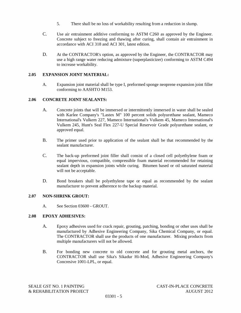
SEALE GST NO. 1 PAINTING CAST-IN-PLACE CONCRETE& REHABILITATION PROJECT AUGUST 2012
03301 - 5
5. There shall be no loss of workability resulting from a reduction in slump.
C. Use air entrainment additive conforming to ASTM C260 as approved by the Engineer.Concrete subject to freezing and thawing after curing, shall contain air entrainment inaccordance with ACI 318 and ACI 301, latest edition.
D. At the CONTRACTOR's option, as approved by the Engineer, the CONTRACTOR mayuse a high range water reducing admixture (superplasticizer) conforming to ASTM C494to increase workability.
2.05 EXPANSION JOINT MATERIAL:
A. Expansion joint material shall be type I, preformed sponge neoprene expansion joint fillerconforming to AASHTO M153.
2.06 CONCRETE JOINT SEALANTS:
A. Concrete joints that will be immersed or intermittently immersed in water shall be sealedwith Karlee Company's "Lastex M" 100 percent solids polyurethane sealant, MamecoInternational's Vulkem 227, Mameco International's Vulkem 45, Mameco International'sVulkem 245, Hunt's Seal Flex 227-U Special Reservoir Grade polyurethane sealant, orapproved equal.
B. The primer used prior to application of the sealant shall be that recommended by thesealant manufacturer.
C. The back-up preformed joint filler shall consist of a closed cell polyethylene foam orequal impervious, compatible, compressible foam material recommended for retainingsealant depth in expansion joints while curing. Bitumen based or oil saturated materialwill not be acceptable.
D. Bond breakers shall be polyethylene tape or equal as recommended by the sealantmanufacturer to prevent adherence to the backup material.
2.07 NON-SHRINK GROUT:
A. See Section 03600 - GROUT.
2.08 EPOXY ADHESIVES:
A. Epoxy adhesives used for crack repair, grouting, patching, bonding or other uses shall bemanufactured by Adhesive Engineering Company, Sika Chemical Company, or equal.The CONTRACTOR shall use the products of one manufacturer. Mixing products frommultiple manufacturers will not be allowed.
B. For bonding new concrete to old concrete and for grouting metal anchors, theCONTRACTOR shall use Sika's Sikadur Hi-Mod, Adhesive Engineering Company'sConcresive 1001-LPL, or equal.

SEALE GST NO. 1 PAINTING CAST-IN-PLACE CONCRETE& REHABILITATION PROJECT AUGUST 2012
03301 - 6
C. For patching concrete surfaces, making high strength epoxy grout or concrete, and forgrouting metal anchors the CONTRACTOR shall use Sika's Sikadur Hi-Mod LV,Adhesive Engineering Company's Concresive Structural Concrete Bonding ProcessSystem, or equal.
D. For pressure injection or gravity feed grouting the CONTRACTOR shall use Sika'sSikadur Hi-Mod LV, Adhesive Engineering Company's Concresive Structural ConcreteBonding Process System, or equal.
2.09 LIQUID CONCRETE CURING COMPOUND:
A. The curing compound shall conform to the requirements and provisions of ASTM C309and shall not prove detrimental to the surface of the concrete. All curing compoundsshall be white. Manufactured by Hunt Process Corp. or equal.
2.10 SHEET CURING MATERIALS:
A. Sheet curing materials shall conform to the requirements of ASTM C171 and shallconsist of waterproof paper, polyethylene film, or white burlap-polyethylene sheets. Anysheet materials selected for use shall be non-staining.
PART 3 EXECUTION
3.01 PREPARATION BEFORE PLACING:
A. Remove excess water from forms prior to placing concrete. Divert any flow fromwashing over freshly placed concrete. Remove hardened concrete, debris, and foreignmaterials from interior of forms and from inner surfaces of mixing and conveyingequipment.
B. Reinforcement and forms shall have been installed in accordance with the provisions ofSection 03100 – Concrete Formwork and Section 03200 – Concrete Reinforcement.Embedded metal shall be free from old mortar, oils, mill scale, and other encrustations orcoatings that might reduce bonding.
C. Wet wood forms sufficiently to tighten up cracks and to reduce suction and maintainconcrete workability.
D. Fine grade subgrades so that they are smooth and level. Subgrades should be lightlydampened twenty four (24) hours in advance of placing. When aggregate fill bases arespecified, place 30-mil plastic sheeting on the base course to retain mix fines within themix and prevent their migration into the base course.
E. For those surfaces to which new work is to be bonded, conform to the requirementsherein specified in Paragraph 3.02, Joints in Concrete. For abutting surfaces that are notto be bonded to new work, clean surfaces to remove dirt and other deleterious substanceswhich may contaminate or interfere with the new work.
3.02 JOINTS IN CONCRETE:
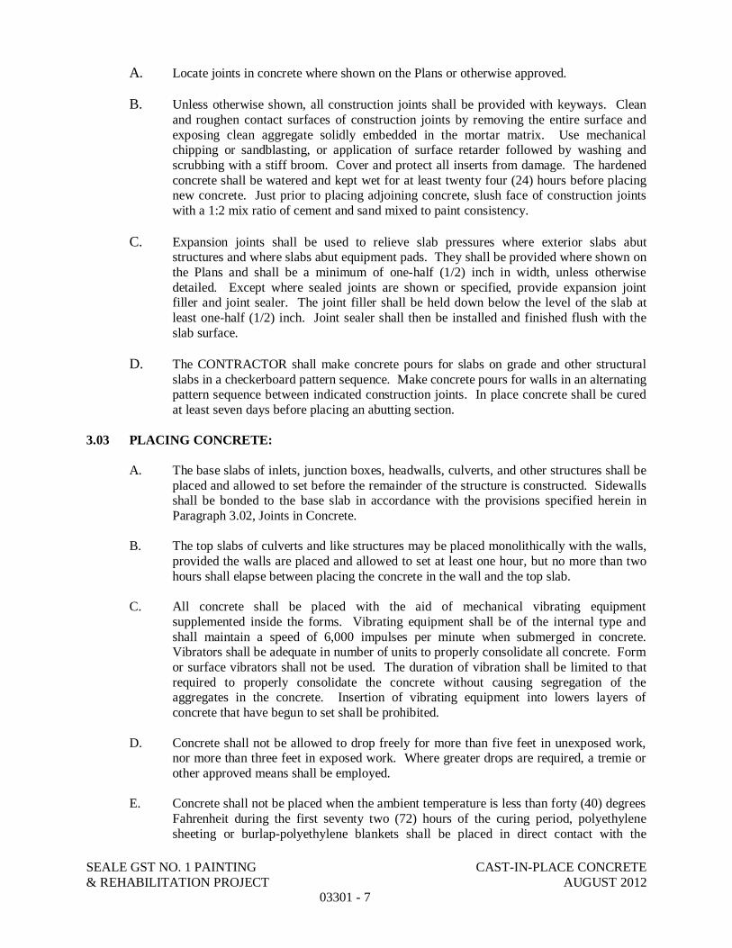
SEALE GST NO. 1 PAINTING CAST-IN-PLACE CONCRETE& REHABILITATION PROJECT AUGUST 2012
03301 - 7
A. Locate joints in concrete where shown on the Plans or otherwise approved.
B. Unless otherwise shown, all construction joints shall be provided with keyways. Cleanand roughen contact surfaces of construction joints by removing the entire surface andexposing clean aggregate solidly embedded in the mortar matrix. Use mechanicalchipping or sandblasting, or application of surface retarder followed by washing andscrubbing with a stiff broom. Cover and protect all inserts from damage. The hardenedconcrete shall be watered and kept wet for at least twenty four (24) hours before placingnew concrete. Just prior to placing adjoining concrete, slush face of construction jointswith a 1:2 mix ratio of cement and sand mixed to paint consistency.
C. Expansion joints shall be used to relieve slab pressures where exterior slabs abutstructures and where slabs abut equipment pads. They shall be provided where shown onthe Plans and shall be a minimum of one-half (1/2) inch in width, unless otherwisedetailed. Except where sealed joints are shown or specified, provide expansion jointfiller and joint sealer. The joint filler shall be held down below the level of the slab atleast one-half (1/2) inch. Joint sealer shall then be installed and finished flush with theslab surface.
D. The CONTRACTOR shall make concrete pours for slabs on grade and other structuralslabs in a checkerboard pattern sequence. Make concrete pours for walls in an alternatingpattern sequence between indicated construction joints. In place concrete shall be curedat least seven days before placing an abutting section.
3.03 PLACING CONCRETE:
A. The base slabs of inlets, junction boxes, headwalls, culverts, and other structures shall beplaced and allowed to set before the remainder of the structure is constructed. Sidewallsshall be bonded to the base slab in accordance with the provisions specified herein inParagraph 3.02, Joints in Concrete.
B. The top slabs of culverts and like structures may be placed monolithically with the walls,provided the walls are placed and allowed to set at least one hour, but no more than twohours shall elapse between placing the concrete in the wall and the top slab.
C. All concrete shall be placed with the aid of mechanical vibrating equipmentsupplemented inside the forms. Vibrating equipment shall be of the internal type andshall maintain a speed of 6,000 impulses per minute when submerged in concrete.Vibrators shall be adequate in number of units to properly consolidate all concrete. Formor surface vibrators shall not be used. The duration of vibration shall be limited to thatrequired to properly consolidate the concrete without causing segregation of theaggregates in the concrete. Insertion of vibrating equipment into lowers layers ofconcrete that have begun to set shall be prohibited.
D. Concrete shall not be allowed to drop freely for more than five feet in unexposed work,nor more than three feet in exposed work. Where greater drops are required, a tremie orother approved means shall be employed.
E. Concrete shall not be placed when the ambient temperature is less than forty (40) degreesFahrenheit during the first seventy two (72) hours of the curing period, polyethylenesheeting or burlap-polyethylene blankets shall be placed in direct contact with the

SEALE GST NO. 1 PAINTING CAST-IN-PLACE CONCRETE& REHABILITATION PROJECT AUGUST 2012
03301 - 8
concrete. When concrete is placed in temperatures above eighty five (85) degrees anapproved retarding agent, meeting the requirements of Paragraph 2.04, Admixtures, willbe required in all concrete used in superstructures and top slabs of culverts.
3.04 FORM REMOVAL:
Forms shall be removed only with the approval of the Engineer and in a manner to ensurecomplete safety of the structure where the structure is supported on shoring. Form removal fromstructures shall not begin until the concrete has attained the following required compressivestrengths:
A. Vertical forms shall not be removed until the concrete has set a minimum of twenty four(24) hours and has attained a minimum compressive strength of 500 psi.
B. When wall and top forms are placed monolithically, wall forms shall not be removeduntil the concrete has attained a minimum strength of 2,000 psi.
C. Forms for the top slab shall not be removed until the top slab has attained a minimumcompressive strength of 2,000 psi.
3.05 FINISHES:
Finishes for concrete surfaces shall comply with the following:
A. Rough Finish - Concrete for which no other finish is indicated or specified shall have finsand rough edges removed.
B. Smooth Finish - Smooth finish shall be given to the interior of junction boxes, inlets,culverts, and other structures indicated on the Plans. Joint marks, fins, and rough edgesshall be smoothed off and blemishes shall be removed leaving finished surfaces smoothand unmarred subject to approval by the Engineer.
C. Floor Finish - Floor finish shall be given to the floors of all inlets, culverts, and otherstructures, and shall be struck off true to the required grade as shown on the Plans andfloated to a smooth, even finish by manual or mechanical methods. No coarse aggregateshall be visible after finishing.
D. Rubbed Finish - All exposed surfaces of retaining walls, wing walls, headwalls, and otherstructures after patching and pointing has been completed, and the surface has beenwetted, shall be given a first rubbing with a No. 16 carborundum stone. After the firstrubbing is completed and the ground material has been evenly spread, the material shallbe allowed to reset. After sufficient aging, the surface shall be wetted and given a finishrubbing with a No. 30 carborundum stone, after which the surface shall be neatly stripedwith a brush and allowed to reset. On the inside surfaces of all culvert walls an area fromthe top of the slab, on a line thirty (30) degrees down from vertical, to the bottom slabshall be rubbed as specified above.
E. The entire structure shall be left with a clear neat uniform finish, free from markings andshall be uniform in color.

SEALE GST NO. 1 PAINTING CAST-IN-PLACE CONCRETE& REHABILITATION PROJECT AUGUST 2012
03301 - 9
F. Sidewalk surfaces shall be given a wood float finish, a light broom finish, or may bestriped with a brush as directed by the Engineer or shown in the Plans.

SEALE GST NO. 1 PAINTING CAST-IN-PLACE CONCRETE& REHABILITATION PROJECT AUGUST 2012
03301 - 10
3.06 CURING:
Immediately after placing or finishing, concrete surfaces not covered by forms shall be protectedfrom loss of surface moisture for not less than four curing days. When forms are left in placethey shall be kept sufficiently wet to reduce cracks in the forms and prevent the form joints fromopening. If forms are removed before four curing days have transpired, the formed surface shallbe protected for the remainder of the four day period. Protection and curing shall beaccomplished by one of the following methods and shall be subject to the approval of theEngineer:
A. Water Curing - Water curing shall be effected by covering exposed surface with sheetcuring materials. In the event white burlap-polyethylene sheets are used, these sheetsshall be previously wetted before applying, and kept thoroughly wet during the entirecuring period.
B. Liquid Curing Compound - Liquid curing compound shall be applied in accordance withthe recommendations of the manufacturer.
END OF SECTION

This page intentionally left blank.
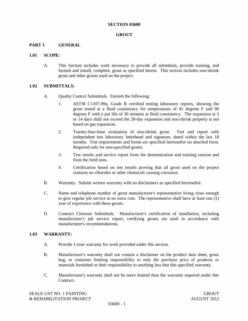
SEALE GST NO. 1 PAINTING GROUT& REHABILITATION PROJECT AUGUST 2012
03600 - 1
SECTION 03600
GROUT
PART 1 GENERAL
1.01 SCOPE:
A. This Section includes work necessary to provide all submittals, provide training, andfurnish and install, complete, grout as specified herein. This section includes non-shrinkgrout and other grouts used on the project.
1.02 SUBMITTALS:
A. Quality Control Submittals. Furnish the following:
1. ASTM C1107-89a, Grade B certified testing laboratory reports, showing thegrout tested at a fluid consistency for temperatures of 45 degrees F and 90degrees F with a pot life of 30 minutes at fluid consistency. The expansion at 3or 14 days shall not exceed the 28-day expansion and non-shrink property is notbased on gas expansion.
2. Twenty-four-hour evaluation of non-shrink grout. Test and report withindependent test laboratory letterhead and signature, dated within the last 18months. Test requirements and forms are specified hereinafter on attached form.Required only for non-specified grouts.
3. Test results and service report from the demonstration and training session andfrom the field tests.
4. Certification based on test results proving that all grout used on the projectcontains no chlorides or other chemicals causing corrosion.
B. Warranty. Submit written warranty with no disclaimers as specified hereinafter.
C. Name and telephone number of grout manufacturer's representative living close enoughto give regular job service at no extra cost. The representative shall have at least one (1)year of experience with these grouts.
D. Contract Closeout Submittals. Manufacturer's certification of installation, includingmanufacturer's job service report, certifying grouts are used in accordance withmanufacturer's recommendations.
1.03 WARRANTY:
A. Provide 1-year warranty for work provided under this section.
B. Manufacturer's warranty shall not contain a disclaimer on the product data sheet, groutbag, or container limiting responsibility to only the purchase price of products ormaterials furnished or their responsibility to anything less that this specified warranty.
C. Manufacturer's warranty shall not be more limited than the warranty required under thisContract.

SEALE GST NO. 1 PAINTING GROUT& REHABILITATION PROJECT AUGUST 2012
03600 - 2
D. Manufacturer shall warrant participation with Contract in replacing or repairing groutfound to be defective due to faulty materials, as determined by industry standard testmethods.
1.04 QUALITY ASSURANCE:
A. Preinstallation Demonstrations and Training.
1. Establish a location on project site and schedule a time for the groutmanufacturer's demonstration and training session of the proposed non-shrinkgrouts to be used on the project. The non-shrink grouts shall be mixed tospecified consistency, tested, placed, and curing initiated on actual projectplacements such as base plates and tie holes to provide actual on-the-job trainingfor CONTRACTOR and Owner.
2. Conduct the training session using a minimum of five bags for each of CategoryII and Category III grout, mix the grout to fluid consistency, and conduct flowcone and two bleed tests, make a minimum of six cubes for testing of two cubesat 1, 3 and 28 days, and then use the final work for the project. TheCONTRACTOR shall have the employees who will be doing this work presentand have them actually participating in this training and demonstration work.The training shall include the methods for curing of the grout.
3. The grout manufacturer shall also mix sufficient Category I grout for a minimumof 15 tie holes and shall train the CONTRACTOR's employees how to performthe work and cure the grout with the employees assisting in the mixing and actualsealing of the tie holes.
4. If the project includes patching, through bolt holes, and block outs such as forgate guides, the manufacturer shall also mix and train the CONTRACTOR'semployees how to install and cure each of these applications.
5. Transport the test cubes to an independent test laboratory, obtain the test reports,pay for these tests, and submit a report of these demonstration and training testcube strengths to the Owner.
PART 2 PRODUCTS
2.01 NONSHRINK GROUTS:
A. Provide grouts free of chlorides and other chemicals that cause corrosion.
B. Non-shrink Grout. Provide non-shrink grout for applications in the grout category asspecified in Table 1.

SEALE GST NO. 1 PAINTING GROUT& REHABILITATION PROJECT AUGUST 2012
03600 - 3
Table 1
Temperature Range Maximum Placing TimeApplication 40 to 100 F 20 min Greater than
20 minFilling tie holes I I IBlock outs for gate guides I or II I IIPrecast joints I or II I IIColumn base plates single-story I or II I IIMachine bases 25 hp or less II II IIBases for precast wall sections II II IIBase plates for columns over one story II II IIPrecast base joints higher than one story II II IIThrough-bolt openings II II IIPatching concrete walls II II IIMachine bases 26 hp and up III III IIIBase plates and/or soleplates with vibration,thermal movement, etc.
III III III
C. Non-shrink Grout, Category I. Nonmetallic, non gas-liberating, flowable grouts meetingthe specified test requirements and applications.
1. A prepackaged natural aggregate grout, requiring only the addition of water.Mix, place, and cure demonstrated by the manufacturer during the demonstrationand training session.
2. Meet ASTM C1107-89a requirements when tested at:
a. Flowable consistency (140 percent flow on ASTM C230, five drops in30 seconds).
b. Flowable for 15 minutes.
c. Fluid working time of at least 30 minutes.
3. The grout when tested shall not bleed at maximum allowed water.
4. The non-shrink property of the grout shall not be based on gas or gypsumexpansion.
5. Grout shall have a minimum strength of 3,000 psi at 3 days, 5,000 psi at 7 days,and 7,000 psi at 28 days.
D. Non-shrink Grout, Category II. Nonmetallic, non gas-liberating, natural aggregate fluidgrouts meeting the specified test requirements and applications.
1. A prepackaged natural aggregate grout, requiring only the addition of water.Mix, place, and cure demonstrated by the manufacturer during the demonstrationand training session.
2. Meet the requirements of CRD-C621-89 and ASTM C1107-89a, Grade B whentested at:
a. Fluid consistency (20 to 30 seconds) per CRD-C611-89.
b. At temperatures of 45, 70 and 90 degrees F.

SEALE GST NO. 1 PAINTING GROUT& REHABILITATION PROJECT AUGUST 2012
03600 - 4
3. Provide certification together with independent test data that the expansion at 3or 14 days does not exceed the 28-day expansion and that its non-shrink propertyis not based on gas or gypsum expansion.
4. The fluid grout shall pass through the flow cone, with a continuous flow, 1 hourafter mixing.
5. Grout shall have a minimum strength of 2,500 psi at 1 day, 4,500 psi at 3 days,and 7,000 psi at 28 days.
6. Grout shall be pretested within the last 18 months per the hereinafter specified24-hour grout test requirements.
E. Non-shrink Grout, Category III. Metallic, non gas-liberating, fluid grouts meeting thespecified test requirements and applications.
1. A prepackaged metallic aggregate grout, requiring only the addition of water.Mix, place, and cure demonstrated by the manufacturer during the demonstrationand training session.
2. Meet the requirements of CRD-C621-89 and ASTM C1107-89a, Grade B whentested at:
a. Fluid consistency (20 to 30 seconds) per CRD-C611-89.
b. At temperatures of 45, 70, and 90 F.
c. Fluid working time of at least 30 minutes.
3. Provide certification together with independent test data that the expansion at 3or 14 days does not exceed the 28-day expansion and that its nonshrink propertyis not based on gas or gypsum expansion.
4. The fluid grout shall pass through the flow cone, with a continuous flow, 1 hourafter mixing.
5. Grout shall have a minimum strength of 4,000 psi at 1 day, 5,000 psi at 3 days,and 9,000 psi at 28 days.
6. Test per the hereinafter specified 24-hour grout test requirements.
F. Non-shrink Grout Manufacturers:
1. Master Builders Co., Cleveland, OH.
2. Euclid Chemical Co., Cleveland, OH.
3. Dayton Superior Corp., Miamisburg, OH.
G. Grout for Horizontal Construction Joints in Walls: flowable, consisting of sand, water,and minimum 12 sacks of cement per cubic yard.
PART 3 EXECUTION
3.01 PLACING GROUT:
A. Place and cure non-shrink grout as demonstrated by the manufacturer during thedemonstration and training session.

SEALE GST NO. 1 PAINTING GROUT& REHABILITATION PROJECT AUGUST 2012
03600 - 5
B. Non-shrink Grout, Category I and II. For formwork tie holes or through-bolt holes, fillspace with dry pack dense grout hammered in with steel tool and steel hammer. Forthrough-bolt holes, coordinate the dry pack dense grout application with the vinyl plug.
C. Location for Use of Various Types of Non-shrink Grout as shown and specifiedhereinbefore.
D. Horizontal Construction Joints in Reinforced Concrete Walls.
1. Use positive measuring device such as a bucket or other device that will containonly enough sand-cement grout, specified hereinbefore, for depositing in oneplace in the wall to ensure that portion of the form does not receive too muchgrout. Limit grout placement to 2-inch maximum thickness.
2. Do not deposit grout from pump hoses or large concrete buckets unlessinspection windows close to the joint are available to allow visual measurementof grout thickness and means for grout removal are available for removal ofexcess grout.
3.02 GROUTING MACHINERY FOUNDATIONS:
A. Block out original concrete or finish off a sufficient distance below bottom of machinerybase to provide for thickness of grout as shown. Prepare the concrete surface bysandblasting or chipping or by other mechanical means to remove any soft material.
B. Set machinery in position and wedge to proper elevation by steel wedges or use cast-inleveling bolts.
C. Form with watertight forms at least two (2) inches higher than the bottom of the plate.
D. Fill space between bottom of machinery base and original concrete pour with fluid non-shrinking type grout as specified and in accordance with manufacturer's demonstrationinstructions.
3.03 FIELD TESTS:
A. Evaluation and Acceptance of Non-shrink Grout. Provide a flow cure and cube moldswith restraining plates on site. Continue tests during this project as demonstrated bygrout manufacturer before grouting began, as follows:
1. Perform flow cone test and bleed tests and make three (2-inch by 2-inch) cubesfor each twenty five (25) cubic feet of each type of non-shrink grout used. Cubemolds shall have restraining caps specified per COE CRD-C-621.
2. On large grouting placements make three more cubes, one more flow cone testand one more bleed test for each additional 25 cubic feet of non-shrink groutplaced.
3. Flow. As specified hereinbefore.
4. Grout with flows outside the specified range shall be rejected.
5. Non-shrink grout cubes shall test equal to or greater than minimum strength asspecified.

SEALE GST NO. 1 PAINTING GROUT& REHABILITATION PROJECT AUGUST 2012
03600 - 6
6. Strength Test Failures. Reject non-shrink grout work and required removal andreplacement of grout with material meeting these Specifications with noadditional compensation.
7. Perform bleeding test to show that grout does not bleed. Test fails if groutbleeds.
8. Store cubes at 70 F.
9. An independent testing laboratory shall prepare, store, cure, and test cubes perCRD-C621-89.
10. Owner will pay costs for the independent test laboratory work to prepare,transport, store, cure, and test the strength samples. The contractor shall assistthe independent test laboratory staff during this work, with costs included in thelump sum bid.
B. Evaluation and Acceptance of Other Grout. The Owner will test and evaluate other groutwith samples furnished by the CONTRACTOR.
3.04 MANUFACTURER'S SERVICES:
A. Furnish non-shrink grout manufacturer's representative as follows:
1. Qualifications: an authorized and trained representative of the groutmanufacturer.
2. Responsibilities.
a. Coordinate demonstrations, training sessions, and other site visits withthe CONTRACTOR.
b. Provide and conduct onsite demonstration and training sessions for bleedtests, proper mixing, flow cone measurement, cube testing, placement,and curing for each category or type of non-shrink grout used and foreach use as specified.
c. Coordinate to ensure necessary equipment and materials are available fordemonstration.
d. Check non-shrink grouting during the job with enough frequency to writejob service report to describe grout application and workmanship inrelation to manufacturer's recommendations.
END OF SECTION

SEALE NO.1 GST PAINTING GROUT& REHABILITATION PROJECT AUGUST 2012
03600-7
_____________________________(Test Lab Name)_____________________________(Address)_____________________________(Phone No.)
24-HOUR EVALUATION OF NONSHRINK GROUT TEST FORM
DESCRIPTION: 24-hour evaluation and analysis of non-shrink grout in accordance withrequirements listed herein.
* This evaluation does not supersede any standard ASTM, CRD, or othertests required by specifier to qualify as an approved grout for the projectat hand.
OBJECTIVE: To define a standard set of tests that any local certified independent laboratorycan perform and complete within a 24-hour period. Costs to run tests will beborne by the manufacturer of the grout to be tested or by whoever requests asubstitute for the specified grouts.
SCOPE: Utilize test procedures providing 24-hour results which attempt to duplicate fieldgrouting demands. This evaluation is intended to prove a manufacturer's qualityand viability to perform to standards described by specifier.
PRIOR TO TEST: Secure five bags of each grout to be tested:
1. From local dealer/jobber, preferably from ultimate supplier of grout to thejob for which grout is specified.
2. All five bags should be of the same lot number.3. Obtain data/literature pertaining to grout being tested.
ANSWER THE FOLLOWING QUESTIONS CONCERNING GROUT TO BE TESTED FROMLITERATURE/DATA/PRINTING ON BAG:
A. Is all product data and warranty information contained in companyliterature/data?
Yes_____ No_____
B. Is it pertinent? Do literature and bag information agree? Yes_____ No_____
C. Does the manufacturer warranty the grout in accordance with projectspecifications?
Yes_____ No_____
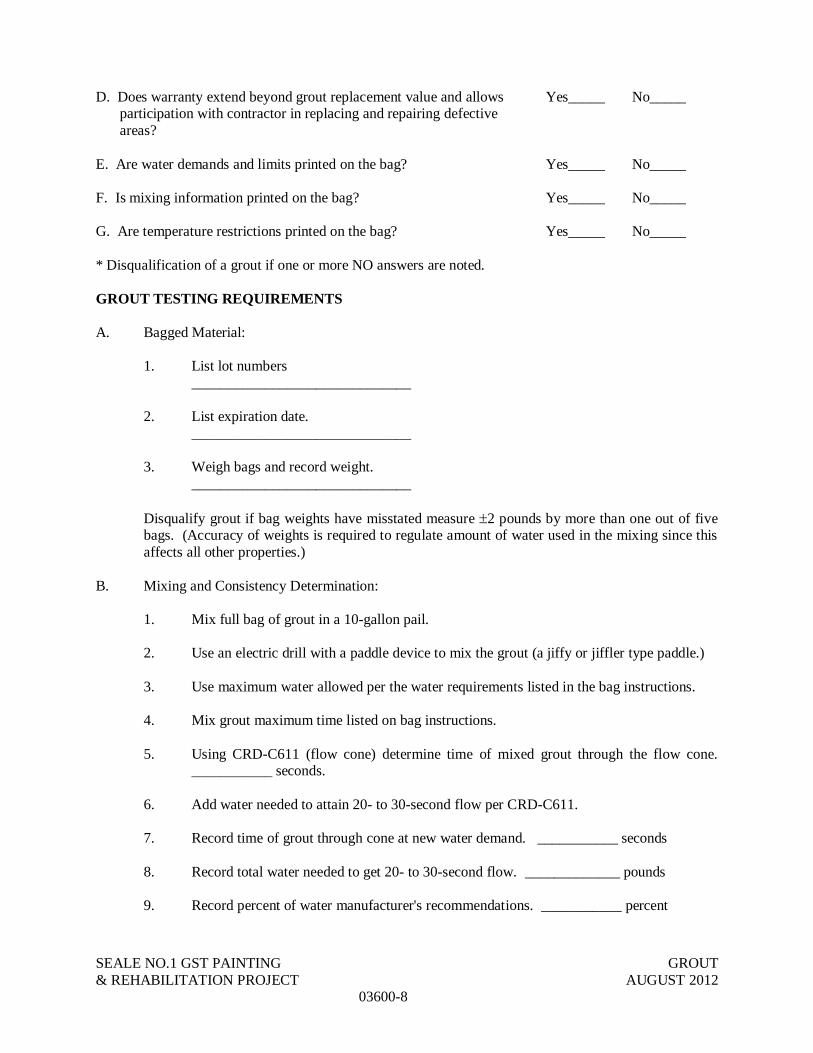
SEALE NO.1 GST PAINTING GROUT& REHABILITATION PROJECT AUGUST 2012
03600-8
D. Does warranty extend beyond grout replacement value and allowsparticipation with contractor in replacing and repairing defectiveareas?
Yes_____ No_____
E. Are water demands and limits printed on the bag? Yes_____ No_____
F. Is mixing information printed on the bag? Yes_____ No_____
G. Are temperature restrictions printed on the bag? Yes_____ No_____
* Disqualification of a grout if one or more NO answers are noted.
GROUT TESTING REQUIREMENTS
A. Bagged Material:
1. List lot numbers______________________________
2. List expiration date.______________________________
3. Weigh bags and record weight.______________________________
Disqualify grout if bag weights have misstated measure 2 pounds by more than one out of fivebags. (Accuracy of weights is required to regulate amount of water used in the mixing since thisaffects all other properties.)
B. Mixing and Consistency Determination:
1. Mix full bag of grout in a 10-gallon pail.
2. Use an electric drill with a paddle device to mix the grout (a jiffy or jiffler type paddle.)
3. Use maximum water allowed per the water requirements listed in the bag instructions.
4. Mix grout maximum time listed on bag instructions.
5. Using CRD-C611 (flow cone) determine time of mixed grout through the flow cone.___________ seconds.
6. Add water needed to attain 20- to 30-second flow per CRD-C611.
7. Record time of grout through cone at new water demand. ___________ seconds
8. Record total water needed to get 20- to 30-second flow. _____________ pounds
9. Record percent of water manufacturer's recommendations. ___________ percent

SEALE NO.1 GST PAINTING GROUT& REHABILITATION PROJECT AUGUST 2012
03600-9
C. When fluid grout is specified and additional water is required above manufacturer's listedmaximum water, CRD-C621 must run at the new water/grout ratio to determine whether thisgrout passes using the actual water requirements to be fluid. Use this new water/grout ratio on allremaining tests.
D. Bleed Test:
1. Fill two gallon cans half full of freshly mixed grout at ambient temperatures required foreach category and at consistency specified for each.
2. Place one can of grout in tub of ice water; leave one can at ambient temperature.
3. Cover top of both cans with a glass or plastic plate to prevent evaporation.
4. Maintain 38 to 42 degrees F temperature with grout placed in ice; maintain ambienttemperature for second container, for 1 hour.
5. Visually check for bleed water at 15-minute intervals for 2 hours.
6. Make final observation at 24 hours.
Disqualify grout if it bleeds even a small amount at the temperatures specified for the categoryintended for use.
E. Extended Time Flow Test (for Category II and III):
1. Leave the grout in the mix can and mix it with the drill mixer every 5 minutes for 20seconds. Maintain this process for 1 hour at ambient temperatures of 40, 80, and 100 F.
2. Take a CRD-C611 flow cone test of the grout at 20, 40, and 60 minutes and record theflow time.
a. 20 min ____, sec. @ 40 Fb. 40 min ____, sec. @ 40 Fc. 60 min ____, sec. @ 40 Fd. 20 min ____, sec. @ 80 Fe. 40 min ____, sec. @ 80 Ff. 60 min ____, sec. @ 80 Fg. 20 min ____, sec. @ 100 Fh. 40 min ____, sec. @ 100 Fi. 60 min ____, sec. @ 100 F
Disqualify any category grout that will not go through the flow cone with continuous flow after60 minutes. Disqualify any category grout for high temperature grouting environments that willnot go through the flow cone with a continuous flow after 60 minutes at temperature 40, 80, and100 F.
___________ ___________Qualified Disqualified

SEALE NO.1 GST PAINTING GROUT& REHABILITATION PROJECT AUGUST 2012
03600-10
F. 24-Hour Strength Test:
1. Using the grout left in the mixing cans per CRD-C621-89 as specified hereinbefore forthe mixing and consistency determination test and for the extended time flow test; make aminimum of nine cube samples.
2. Store cubes at 70 F for 24 hours.
3. Record average compressive strength of nine cubes at 24 hours.
Disqualify grout if 24-hour compressive strengths are less than 1,000 psi for grouts claiming fluidplacement capabilities.
Grouts that have not been disqualified after these tests are OK for use on the project for theapplication shown in the specified table.
___________________________________ ___________________________Signature of Independent Test Lab Date Test ConductedPersonnel Supervising and Certifyingthese Test and Test Results

SAN ANTONIO WATER SYSTEM CANOPY COVER SEALE PUMP STATION IMPROVEMENTS PROJECT JULY 2012
05120-1
SECTION 05120
STRUCTURAL STEEL PART 1 - GENERAL 1.1 RELATED DOCUMENTS A. Drawings and general provisions of Contract, including General and Supplementary
Conditions and Division-1 Specification sections, apply to work of this section. 1.2 DESCRIPTION OF WORK A. Extent of structural steel work is shown on drawings including schedules, notes and
details which show size and location of members, typical connections, and type of steel required. Furnish all labor, materials, services, equipment and appliances required in conjunction with or related to the furnishing, fabrication, delivery, and erection of all structural steel defined below. Include all supplementary parts, members and connections necessary to complete the structural steel work, regardless of whether all such items are specifically shown or specified on the drawings.
B. Structural steel shall be defined as that work prescribed in Section 2.1 of the AISC Code
of Standard Practice and the following items: shelf angles, angle frames for openings in floors and roofs, cooling tower grillage, support frames for elevator machines not otherwise furnished by the elevator manufacturer, steel floor framing supporting elevator equipment, all steel supports for elevator guide rails, steel crane rails and stops, miscellaneous metal deck support and edge angles, shop welded metal studs, all connection material, temporary construction bracing, and all other structural steel shown or specified on the drawings to be part of the work. Labor shall include shop painting as specified, field touch-up painting, and grouting of base plates and bearing plates.
C. Miscellaneous metal fabrications, architecturally exposed structural steel, metal stairs,
steel joists, and metal deck are specified elsewhere in these Specifications. 1.3 QUALIFICATIONS 1. Fabricator: The structural steel fabricator shall have not less than 10 years experience in
the successful fabrication of structural steel similar to this project. Evidence of compliance with this section shall be submitted to the Architect/Engineer.
2. Erector: The structural steel erector shall have not less than 5 years successful
experience in the erection of structural steel of a similar nature to this project. Evidence of compliance with this section shall be submitted to the Architect/Engineer.
1.4 QUALITY ASSURANCE The Contractor is responsible for quality control, including workmanship and materials furnished by his subcontractors and suppliers. A. Codes and Standards: Comply with provisions of the following, except as otherwise indicated:

SAN ANTONIO WATER SYSTEM CANOPY COVER SEALE PUMP STATION IMPROVEMENTS PROJECT JULY 2012
05120-2
1. All federal (OSHA), state and local laws which govern safety requirements for steel erection and other requirements if more stringent than the codes and standards enumerated below.
2. AISC "Code of Standard Practice for Steel Buildings and Bridges", 13th edition. 3. AISC "Specification for the Design, Fabrication, and Erection of Structural Steel
for Buildings", latest edition. 4. AISC "Specification for Structural Joints using ASTM A 325 or A 490 Bolts"
approved by the Research Council on Riveted and Bolted Structural Joints of the Engineering Foundation (Research Council on Structural Connections), latest edition.
5. AWS D1.1 "Structural Welding Code - Steel". 6. "Steel Structures Painting Manual", Volumes 1 and 2, Steel Structures Painting
Council. B. Qualifications for Welding Work: Qualify welding processes and welding operators in accordance with AWS "Structural
Welding Code - Steel". 1. Provide certification that welders to be employed in work have satisfactorily
passed AWS qualification tests. 2. If recertification of welders is required, retesting will be Contractor's
responsibility. C. Source Quality Control: Materials and fabrication procedures are subject to inspection
and tests in the mill, shop, and field by the Owner's testing laboratory. Such inspections and tests will not relieve the Contractor of responsibility for providing materials and fabrication procedures in compliance with specified requirements. The Contractor shall promptly remove and replace materials or fabricated components which do not comply.
D. Question about Contract Documents: The Contractor shall promptly notify the
Architect/Engineer whenever design of members and connections for any portion of the structure are not clearly indicated or when other questions exist about the Contract Documents. Such questions shall be resolved prior to the submission of shop drawings.
E. Testing Laboratory Services: See Structural Drawings for required testing. Inspection or
testing by the Owner does not relieve the Contractor of his responsibility to perform the Work in accordance with the Contract Documents.
1.5 SUBMITTALS A. Shop Drawings: 1. General Requirements: Submit shop drawings including complete details and
schedules for fabrication and assembly of structural steel members, and details, schedules, procedures and diagrams showing sequence of erection. Shop drawings not complying with the above requirements will not be reviewed. Structural steel shop drawings shall include the following minimum information:
SAN ANTONIO WATER SYSTEM CANOPY COVER SEALE PUMP STATION IMPROVEMENTS PROJECT JULY 2012
05120-3
a. Include details of cuts, connections, camber, holes, and other pertinent data. Indicate welds by standard AWS symbols, and show size, length, and type of each weld. Holes, flange cuts, slots and openings shall be made as required by the structural drawings, all of which shall be properly located by means of templates.
2. The fabricator alone shall be responsible for all errors of detailing, fabrication,
and for the correct fitting of the structural members. 3. All fabricated material and connections shall fit within architectural constraints. 4. Structural steel members for which shop drawings have not been reviewed and
approved shall not be fabricated. 5. The omission from the shop drawings of any materials required by the Contract
Documents shall not relieve the Contractor of the responsibility of furnishing and installing such materials, even though the shop drawings may have been reviewed and approved.
B. Test Reports: Submit copies of reports of tests conducted on all field-welded
connections that are inspected. Include data on type(s) of tests conducted and test results.
1.6 DELIVERY, STORAGE AND HANDLING A. Deliver materials to site at such intervals to ensure uninterrupted progress of work. B. Deliver anchor bolts and anchorage devices, which are to be embedded in cast-in-place
concrete or masonry, in ample time so as not to delay work. C. Store materials to permit easy access for inspection and identification. Keep steel
members off ground, using pallets, platforms, or other supports. Protect steel members and packaged materials from corrosion and deterioration. Do not store materials on structure in a manner that might exceed allowable loads on or cause distortion or damage to members or supporting structures. Repair or replace damaged materials or structures as directed by Architect/Engineer.
D. Furnish all fuel, maintenance, and equipment required for hoisting and placement of
materials under this contract. E. Process, pay for and maintain all permits and certificates of on-site inspection required
for derricks, cranes and hoisting equipment. No derrick, crane or hoisting equipment shall be operated without a certificate of operation and a certificate of on-site inspection, as required by governing authorities.
1. Wherever the erection equipment is supported by the structure, the Contractor
shall be responsible for the retention of a licensed professional engineer to determine the adequacy of the member supporting the erection equipment in relation to the loads imposed thereon. The Contractor shall submit to the Architect/Engineer, for review, the loads which will be imposed by the erection equipment on the building structure. Where the imposed load exceeds the allowable stresses, the Contractor shall be responsible for any additional materials, supports, bracing, connections and similar measures required to support the imposed load of the equipment while in use, subject to review by the Architect/Engineer.

SAN ANTONIO WATER SYSTEM CANOPY COVER SEALE PUMP STATION IMPROVEMENTS PROJECT JULY 2012
05120-4
2. In addition to the above, all hoisting equipment shall be installed, operated and maintained in accordance with all applicable regulations of authorities having jurisdiction.
3. Street storage and sidewalk crossing permits shall be furnished by the
Contractor. 1.7 JOB CONDITIONS The Contractor shall coordinate the fabrication and erection of all structural steel work with the
work of other trades. The contractor shall verify existing conditions prior to beginning work. The contractor shall verify all dimensions shown on the drawings with existing job conditions prior to beginning work.
PART 2 - PRODUCTS 2.1 MATERIALS A. Structural Steel: All hot rolled steel plates, shapes, sheet piling, and bars shall be new
steel conforming to ASTM Specification A6 "Standard Specification for General Requirements for Rolled Steel Plates, Shapes, Sheet Piling, and Bars for Structural Use".
Structural steel shall comply with the provisions of the following ASTM Specifications as
appropriate for the grades and types, and at the locations as specified on the drawings: 1. Structural Steel Shapes, Plates and Bars - Carbon Steel, ASTM A992 GR50
"Standard Specification for Structural Steel." 2. Pipe Columns - ASTM A53 (Type E or S) Grade B, or ASTM A501. 3. Tube Sections - ASTM A500 Grade B. FY = 46 KSI 4. Connection Material: All connection material except as noted otherwise on the
drawings including bearing plates, gusset plates, stiffener plates, filler plates, angles, etc. shall be A36 steel unless a higher or matching grade of steel with the members connected is required by strength or stiffness calculations and provided the resulting sizes are compatible with the members connected.
B. Structural Bolts and Threaded Fasteners: Structural bolts and threaded fasteners shall
comply with the following ASTM Specifications as appropriate for the types and at the locations as specified on the drawings:
1. ASTM A325 Type 1, "High-Strength Bolts for Structural Steel Joints". 2. Bolts and Nuts, High Strength Bolts: Bolts and nuts for all high strength bolts
shall be heavy hex head conforming to ANSI Standards B18.2.1 and B18.2.2 respectively. Nuts shall conform to ASTM A563, "Standard Specification for Carbon and Alloy Steel Nuts".
3. Washers: All washers shall be circular, flat and smooth and shall conform to the
requirements of Type A washers in ANSI Standard B23.1. Washers for high strength bolts shall be hardened and conform to ASTM F436, Specification for Hardened Steel Washers. Beveled washers for American Standard Beams and channels shall be square or rectangular, shall taper in thickness (16 2/3% slope) with an average thickness of 5/16". When an outer face of a bolted part has a
SAN ANTONIO WATER SYSTEM CANOPY COVER SEALE PUMP STATION IMPROVEMENTS PROJECT JULY 2012
05120-5
slope greater than 1:20 with respect to a plane normal to the bolt axis, a beveled washer shall be used.
4. Bolt Lubrication: All bolts shall be well lubricated at time of installation. Dry,
rusty bolts will not be allowed. Bolts or nuts shall be wax dipped by the bolt supplier or "Johnson's Stick Wax 140" shall be used with all bolts in the shop or field.
5. New Bolts: All bolts shall be new and shall not be reused. C. Electrodes for Welding: Comply with AWS D1.1, "Structural Welding Code - Steel".
Electrodes for various welding processes shall be as specified below: 1. SMAW: E70XX low hydrogen 2. SAW: F7X-EXXX 3. GMAW: ER70S-X 4. FCAW: E7XT-X 5. Weathering Steel Electrodes shall conform to Table 4.1.4 of the AWS D1.1
Manual. Electrodes shall be compatible with parent metal joined. D. Structural Steel Primer Paint: Primer paint shall be one of the following types with the
indicated surface preparation: Red Oxide Shopcoat Primer AKP563 Manufacturer: INSULATE – (845) 786-5000 Product Information: Colors: Gray Oxide Finish: Low sheen Coating Type: Modified Alkyd Resin Mixing Ratio: Single Component VOC 2.78 lbs/gallon (334 grams per liter) Solids by Volume: 53% Recommended Dry Film: 1.5 – 2.5 mils Coverage (Theoretical): 340-566 SF/gallon Drying Time: 2-4 hours to touch; 12 hours to recoat Dry heat resistance: 225 degrees F (107 degrees C) Viscosity: 65-75 KU Weight per Gallon: 12.31 lbs/gallon (1.3 kg/liter) Pot Life: Not applicable Shelf Life: More than one year 1. Physical Properties: a. Flash point 72 degrees F (22 degrees C) Setaflash 2. Limitations: a. Do not use on galvanized metal or under epoxy topcoats. 3. Surface Preparation: All surfaces must be sound, dry, clean and free of oil, grease, dirt, mildew, form release
agents, curing compounds, loose and flaking paint and other foreign substances.

SAN ANTONIO WATER SYSTEM CANOPY COVER SEALE PUMP STATION IMPROVEMENTS PROJECT JULY 2012
05120-6
New Surfaces: Steel – For best results, abrasive blast to a commercial blast (SSPC-SP-6). For mild conditions, a hand or power tool cleaning (SSPC-SP-2) may be satisfactory, but performance is dependent on the degree of cleaning.
Previously Painted Surfaces: Wash and rinse any areas that may have oil or grease residue. Dull glossy areas by light sanding. Remove sanding dust. Remove loose paint. All areas that are rusting, blistering, cracking or peeling must be cleaned to bare metal. If more than 25% of the surface is involved, sandblast the entire surface to a commercial blast and prime. If less than 25% of the surface is involved, clean soiled areas and spot prime.
4. Application: Paint should be stirred to a uniform consistence prior to application. Thinning is usually
not required or desired; however, small amount (5% or less) of mineral spirits may be added depending on local VOC and air quality regulations. Do not apply if air or surface temperature is below 45 degrees F. Relative humidity should be below 90%. Apply by brush, roller or spray.
5. Clean Up: Clean all equipment with TH-0201 Reducer promptly after use. 6. Safety Information See the Material Safety Data Sheet and the product label for complete safety and
precaution requirements. 2.2 FABRICATION A. Shop Fabrication and Assembly: 1. Fabricate and assemble structural assemblies in shop to greatest extent
possible. Fabricate items of structural steel in accordance with AISC Specification and as indicated on approved final shop drawings. Fabricator shall coordinate joint fit-up procedures with erector. Provide camber in structural members where indicated. The General Contractor shall coordinate provision of all erection bolts, lifting lugs or other devices required for erection with the fabricator and the erector.
2. Properly mark and match-mark materials for field assembly. Fabricate for
delivery sequence which will expedite erection and minimize field handling of materials.
3. Clearly mark the grade of steel on each piece, distinguishable in the field from
floor surfaces, for purpose of field inspection and confirmation of grade of steel. B. Dimensional Tolerances: Dimensional tolerances of fabricated structural steel shall
conform to Section 6.4 of the AISC Code of Standard Practice. C. Splices in Structural Steel: Splicing of structural steel members in the shop or the field is
prohibited without prior approval of the Engineer. Any member having a splice not shown and detailed on approved shop drawings will be rejected.
D. Cutting: Manual oxygen cutting shall be done only with a mechanically guided torch. An
unguided torch may be used provided the cut is not within 1/8 inch of the finished dimension and final removal is completed by means such as chipping or grinding to

SAN ANTONIO WATER SYSTEM CANOPY COVER SEALE PUMP STATION IMPROVEMENTS PROJECT JULY 2012
05120-7
produce a smooth surface quality free of notches or jagged edges. All corners shall be smooth and rounded to a minimum 1/2" radius.
2.3 WELDING A. Code: All shop and field welding shall conform to all requirements in the "Structural
Welding Code - Steel", ANSI/AWS D1.1, as published by the American Welding Society (AWS).
B. Welder Certification: All shop and field welders shall be certified according to AWS
procedures for the welding process and welding position used. Submit certification certificates to the Architect for record purposes.
C. Minimum Size and Strength: 1. Fillet Welds: Minimum size of fillet welds shall be as specified in Table 1.17.2A
in the AISC Manual of Steel Construction. 2. Minimum Strength of Welded Connections: Unless noted otherwise on the
drawings, all shop and field welds shall develop the full tensile strength of the member or element joined. All members with moment connections, noted on the drawings with "MC", shall be welded to develop the full flexural capacity of the member, unless noted otherwise on the drawings.
D. Filler Metal Requirements: Weld metal shall be as specified in AISC Manual of Steel
Construction Table 1.5.3. E. Welding Procedures: 1. Welds not specified shall, if possible, be continuous fillet welds developing the
minimum strength, as specified above, using not less than the minimum fillet welds as specified by AISC.
2.4 BOLTING A. Minimum Bolt Diameter: Minimum bolt diameter shall be 3/4 inch. B. Connection Type: Unless noted otherwise on the drawings or in the General Notes, all
bolted connections shall be bearing type connections using standard holes (hole diameter nominally 1/16 inch in excess of nominal bolt diameter) with threads included in the shear planes.
C. Simple Beams: Simple shear connections shall be capable of end rotations of
unrestrained beams as specified in Section 1.15.4 of the AISC Specification. D. Allowable Working Stresses: The allowable working stresses of bolts shall be as
specified in the AISC Specification Table 1.5.2.1 and Tables 2 and 3 of the high strength bolting specification previously cited.
E. Washers: Washers under the bolt head and/or nut shall be used as required by the bolt
specification previously cited. F. New Bolts: All bolts shall be new and shall not be reused. G. Minimum Strength of Bolted Connections: Unless noted otherwise on the drawings, all
shop and field bolted connections shall develop, as applicable, the full tensile or

SAN ANTONIO WATER SYSTEM CANOPY COVER SEALE PUMP STATION IMPROVEMENTS PROJECT JULY 2012
05120-8
compressive strength of the member. All members with bolted moment connections, noted on the drawings with "MC", shall be bolted to develop the full flexural capacity of the member, unless noted otherwise on the drawings.
2.5 CONNECTIONS A. Typical connection details are indicated on the drawings. B. Design Procedure: Exception is taken to the second sentence of Section 4.2.1 of the
AISC Code of Standard Practice for Bridges and Buildings, and the following provisions shall be substituted and made a binding part of the project specifications:
1. Connection types to be used are Type 2 "Simple". C. Type 2 Simple Beam Connections: 1. All typical beam simple connections shall be standard double angle or single
angle framed beam connections using bolts as specified. 2. Single plate "shear tab" connections may be used provided there is no axial force
in the beam and they are designed strictly according to the procedure outlined in "Engineering for Steel Construction" as published by AISC and the paper appearing in the 3rd Quarter, 1984 Engineering Journal "Single Plate Framing Connections with Grade 50 Steel and Composite Construction" as published by AISC.
3. Simple Beam Design Capacity: Unless a larger reaction is shown otherwise on
the plans, minimum design forces shall be as follows: a. Non Composite Beams: Support a reaction R equal to one half the total
uniform load capacity from the table of Uniform Load Constants in the AISC Manual Part 2 for given shape, span, and grade of steel.
D. Struts and Braces: 1. Connections for all struts, hangers, and braces shall have connections designed
to develop the full allowable tensile strength of the member. 2.6 SURFACE PREPARATION AND PAINTING A. Specification: Surface preparation, paint, and painting practices shall conform to the
"Steel Structures Painting Manual", Volumes 1 and 2, as published by the Steel Structures Painting Council (SSPC).
B. Scope: Shop paint all steel. C. Surface Preparation and Primer Paint - Shop Painted Steel: All structural steel specified
to be shop primed shall have paint applied in strict accordance with manufacturer’s instructions using prescribed surface preparation but not less than specified. Paint shall be applied immediately after surface preparation at a rate to provide a uniform dry film thickness of not less than 1.5 mils. Painting methods shall be used which result in full coverage of joints, corners, edges, and all exposed surfaces. Two coats shall be applied to surfaces which are inaccessible after assembly or erection. The color of the second coat shall be changed to distinguish it from the first coat.

SAN ANTONIO WATER SYSTEM CANOPY COVER SEALE PUMP STATION IMPROVEMENTS PROJECT JULY 2012
05120-9
Coordinate shop primer paint requirements with architectural drawings and specifications.
PART 3 - ERECTION 3.1 ERECTION A. Inspection: Erector shall examine areas and conditions under which structural steel work
is to be installed and notify the Contractor and the Architect/Engineer in writing of conditions detrimental to proper and timely completion of the work.
B. Erection Tolerances: Erection tolerances of anchor bolts, embedded items, and all
structural steel shall conform to the AISC Code of Standard Practice. C. Field Assembly of Structural Steel: 1. As erection of the steel progresses, the work shall be fastened securely to take
care of all dead load, wind and erection stresses. Particular care shall be exercised to ensure straightness and tautness of bracing immediately upon raising a steel column.
2. Provide temporary planking and working platforms as necessary to effectively
complete work. 3. Set structural frames accurately to lines and elevations indicated. Align and
adjust various members forming part of complete frame or structure before permanently fastening. Clean bearing surfaces and other surfaces which will be in permanent contact before assembly. Perform necessary adjustments to compensate for discrepancies in elevations and alignment. Level and plumb individual members of structure within specified AISC tolerances. The Contractor shall coordinate with Erector and Fabricator regarding possible discrepancies in member lengths between temperature at time of fabrication and temperatures during erection, and shall make necessary adjustments to ensure plumbness within AISC tolerances at 60°F. Compensate for cumulative welding draw, construction loadings, sequential applications of dead loads, or any other predictable conditions that could cause distortions to exceed tolerance limitations.
4. On exposed welded construction, remove erection bolts, fill holes with plug welds
or filler and grind smooth at exposed surfaces. 5. Comply with AISC Specifications for bearing, adequacy of temporary
connections, alignment, and removal of paint on surfaces receiving field welds. 6. Comply with all bolting and welding requirements of Part 2 of this specification
section. 7. Remove and replace existing finish materials as required to accomplish all work.
The contractor shall comply with all fire codes when performing welding of steel or metal studs.
D. Field Modifications to Structural Steel: Errors in shop fabrication or deformation resulting
from handling and transportation that prevent the proper assembly and structural fitting of parts shall be reported immediately to the Architect/Engineer, and approval of the method of correction shall be obtained. Approved corrections shall be made at no additional cost
SAN ANTONIO WATER SYSTEM CANOPY COVER SEALE PUMP STATION IMPROVEMENTS PROJECT JULY 2012
05120-10
to the Owner. Do not use cutting torches, reamers, or other devices in the field for unauthorized correction of fabrication errors.
E. Miscellaneous Framing: Provide supplemental structural steel support framing for metal
deck where normal deck bearing is interrupted by column flange plates or other framing members and other floor openings whether shown or not on either the architectural, mechanical, or structural drawings.
F. Removal of Erection Aids and Devices: The erector shall remove all erection aids and
devices that interfere with architectural finish or MEP requirements. G. Touch-Up Painting: 1. Immediately after erection, clean field welds, bolted connections, and abraded
areas that have been shop painted. Apply paint to exposed areas using same material and surface preparation as used for shop painting. Apply by brush or spray to provide minimum dry film thickness of 1.5 mils.
2. All field welded galvanized connections shall have welds protected with "Z.R.C.
Cold Galvanizing Compound" as manufactured by Z.R.C. Products Company. 3. Steel Plates Embedded in Concrete: a. Studs shall be welded using automatically timed stud welding equipment
to develop the full capacity of the stud. b. Plates must be unpainted and free of heavy rust, mill scale, dirt, sand or
other foreign material which will interfere with the welding operation. Shop prime all plates and studs after welding unless plates are exposed to the outside in which case the assembly shall be hot dip galvanized after welding.
H. Clean Up: Clean up all debris caused by the Work of this Section, keeping the premises
neat and clean at all times. Replace and repair to like new condition, all damaged areas of the interior and exterior of the building.
END OF SECTION 05120

SAN ANTONIO WATER SYSTEM CANOPY COVER SEALE PUMP STATION IMPROVEMENTS PROJECT JULY 2012
05200-1
SECTION 05200
STEEL JOISTS PART 1 - GENERAL 1.1 RELATED DOCUMENTS Drawings and general provisions of Contract, including General and Supplementary Conditions
and Division-1 Specification sections, apply to work of this section. 1.2 SCOPE OF WORK A. Extent of steel joists is shown on drawings, including basic layout and type of joists
required. B. Quantity of joists required shall be determined from the contract drawings. 1.3 QUALITY ASSURANCE The Contractor is responsible for quality control, including workmanship and materials furnished
by his subcontractors and suppliers. A. Design and Fabrication: Provide joists designed and fabricated in compliance with the
following, and as herein specified. 1. Steel Joist Institute (SJI) Standard Specifications, Load Tables and Weight
Tables for K, LH, and DLH Series Steel Joists, Latest Edition. 2. Recommended Code of Standard Practice for Steel Joists and Joist Girders,
Latest Edition. 3. Local fabrication requirements of governing authorities such as the city, county
and state having jurisdiction over the site where the project is located. 4. American Welding Society AWS D1.1 Structural Welding Code - Steel or SJI
Technical Digest #8 "Welding of Open Web Steel Joists" with successful passage of load tests as defined in this specification section.
5. Acceptable Joist Manufacturers are: a. VULCRAFT – www.vulcraft.com
b. SMI JOIST – www.smijoist.com c. CMC JOIST d. QUINCY JOIST CO. 3. NEW MILIINIUM JOIST CO
1.4 SUBMITTALS A. Product Data: Submit joist manufacturer's certification letter that joists comply with all
documents listed in "Quality Assurance". A sample letter is shown herein for reference. ** Date **
SAN ANTONIO WATER SYSTEM CANOPY COVER SEALE PUMP STATION IMPROVEMENTS PROJECT JULY 2012
05200-2
Bill Reiffert & Associates, Inc. 8918 Tesoro Drive, Suite 108 San Antonio, Texas 78217 Attn: **Name of Project Engineer** Re: Joist Certification, **Project Name** Dear **Name of Project Manager**: (**Name of Joist Manufacturer**) certifies that the members of steel joists on the above
named project are designed and fabricated in accordance with the following: 1. Steel Joist Institute (SJI) Standard Specifications, Load Tables and Weight Tables for K,
LH, and DLH Series Steel Joists, (**specify edition**). 2. Recommended Code of Standard Practice for Steel Joists. (**specify edition**). 3. Project Plans and Specifications. It is understood that the joist designations, except where indicated otherwise in the Contract
Documents, have been selected by the Engineer-of-Record. (**Name of Joist Manufacturer**) further certifies that the steel joist design and preparation of all
shop drawings was prepared under the direct supervision of a professional engineer registered in the state where the project is located (**specify**).
Yours very truly, **Name of Registered Professional Engineer with P.E.** **Embossed stamp affixed.** B. Shop Drawings: Submit detailed drawings showing layout of joist units, connections,
jointing and accessories. Include length, camber, mark, number, type, location and spacing of joists and bridging. Submit details for member splices.
Provide templates or location drawings for installation of anchor bolts. 1.5 DELIVERY, STORAGE AND HANDLING Deliver, store and handle steel joists as recommended in SJI specifications. Handle and store
these in a manner to avoid deforming members and to avoid excessive stresses. 1.6 SHOP INSPECTION Joists shall be inspected by the manufacturer's quality assurance inspector before shipment to
insure compliance of materials and workmanship with the documents specified in this specification. In addition, an independent testing laboratory, if requested by the Owner, shall inspect the joist fabrication at the shop. Cooperate with the Owner's testing laboratory and inspectors in all tests and inspections. Any defects found shall be repaired prior to shipment of the joists.

SAN ANTONIO WATER SYSTEM CANOPY COVER SEALE PUMP STATION IMPROVEMENTS PROJECT JULY 2012
05200-3
PART 2 - PRODUCTS 2.1 MATERIALS A. Steel: Comply with SJI specifications. B. Unfinished Threaded Fasteners: ASTM A307, Grade A, regular hexagon type, low
carbon steel. C. High-Strength Threaded Fasteners: ASTM A 325 or A 490 heavy hexagon structural
bolts with nuts and hardened washers. D. Steel Prime Paint: Comply with SJI specifications. 2.2 FABRICATION A. General: Fabricator shall be a member of the Steel Joist Institute in good standing with a
minimum of 5 years experience. Fabricate steel joists in accordance with all documents listed in "Quality Assurance", except as noted below.
B. Splices in Chord Members: All splices shall be designed and provided in accordance
with SJI Specifications. The splices in each of the two angles or bars of all members shall not be at the same location, but shall be staggered a minimum of 6 inches.
C. Holes in Chord Members: Provide holes in chord members where shown in contract
drawings for securing other work to steel joists; however, deduct area of holes from the area of chord when calculating strength of member.
D. Joists shall be cambered in accordance with SJI standards. Provide all joists with SJI
standard camber unless specified otherwise on the drawings. Review the Structural Drawings and Specifications for information concerning dead loads for joists requiring other than standard camber. Joist camber must be shown on shop drawings submitted for review. Camber not shown on shop drawings shall be cause for rejection of shop drawings.
E. Joist Bearing: Provide minimum end bearing of joists as required by SJI specifications
but subject to requirements below: 1. Joists Less than 60-Foot Span: a. If two joists do not abut each other at a support, provide required joist
bearing centered on the supporting member unless detailed otherwise on the drawings.
b. If two joists abut each other at a support and sufficient minimum bearing
for each joist exists, provide 1/4" space between joist ends centered over the support unless details otherwise on the drawings.
c. If two joists abut each other at a support and sufficient minimum bearing
for each joist does not exist at the support, offset the ends of each joist and center joist bearing on the center of the support.
F. Top Chord Extensions and Extended Ends: Provide top chord extensions and extended
ends on joists where shown in contract drawings complying with the requirements of SJI specification and load tables. Top chord extensions shall extend back to the first interior panel point from the joist exterior panel point as a minimum.

SAN ANTONIO WATER SYSTEM CANOPY COVER SEALE PUMP STATION IMPROVEMENTS PROJECT JULY 2012
05200-4
G. Ceiling Extensions: Provide ceiling extensions in areas having ceilings attached directly
to joist bottom chord. Provide either an extended bottom chord element or a separate unit, to suit manufacturer's standards, of sufficient strength to support ceiling construction. Extend ends to within 1/2" of finished wall surface unless otherwise indicated.
H. Bridging: Provide horizontal and/or diagonal type bridging for all joists, complying with
SJI specifications. 1. Examine the drawings carefully for special bridging requirements. 2. Provide bridging anchors for ends of bridging lines terminating at walls or beams. I. End Anchorage: Provide end anchorages to secure joists to adjacent construction,
complying with SJI specifications, unless otherwise indicated. J. Header Units: Any situation requiring heading of joists not shown on the structural
drawings shall be referred to engineer for framing. K. Shop Painting: Remove loose scale, heavy rust, grease, oil and other foreign materials
from fabricated joists and accessories by rotary wire brushes and/or solvents before application of shop paint.
Apply one shop coat of primer paint to steel joists and accessories, by spray, dipping, or
other method to provide a continuous dry paint film thickness of not less than 0.50 mil. PART 3 - EXECUTION 3.1 STORAGE: Joists shall be stored off the ground. 3.2 ERECTION A. Place and secure steel joists strictly in accordance with SJI code of standard practice,
SJI specifications, final shop drawings, and as herein specified. B. Joists shall be hoisted with a sling. C. Placing Joists: Do not start placement of steel joists until supporting work is in place and
secured. Place joists on supporting work, adjust and align in accurate locations and spacing before permanently fastening.
1. Provide required bridging, connections, and anchors to ensure lateral stability
during construction. Remove as required for architectural, structural, and mechanical clearances after erection.
2. Where open web joist lengths are 40 feet and longer, install a minimum of one
center row of bolted bridging to provide lateral stability before slackening of hoisting lines.
3. Where members support joists from both sides, and the supporting width does
not meet the SJI recommendations for bearing lengths of both joists, then offset joists to provide recommended bearing lengths. Such offsets shall be subject to approval by the Architect/Engineer.

SAN ANTONIO WATER SYSTEM CANOPY COVER SEALE PUMP STATION IMPROVEMENTS PROJECT JULY 2012
05200-5
D. Bridging: Install bridging simultaneously with joist erection, before construction loads are applied. Anchor ends of bridging lines at top and bottom chords where terminating at walls or beams.
E. Damaged Joists shall be repaired as directed by the Structural Engineer or removed from
the site. 3.3 FASTENING JOISTS A. Do not permit erection of decking until joists are secured to supporting members, and are
properly braced. B. Field weld joists to supporting steel framework in accordance with SJI specifications for
type of joists used. Coordinate welding sequence and procedure with placing of joists. C. Joists where shown with bottom chord extensions shall not have the bottom chords
connected to the supporting members until the full dead load is applied. D. Secure joists resting on masonry or concrete bearing surfaces by bedding in grout and
anchoring to masonry or concrete construction as specified in SJI specifications for type of steel joist used.
E. Bolt joists to supporting steel framework in accordance with SJI specifications for type of
joists used. 1. Provide high-strength threaded fasteners for bolted connections of steel joists to
steel columns, and at other locations where shown, installed in accordance with AISC "Specification for Structural Joints Using ASTM A 325 or A 490 Bolts".
F. Touch-Up Painting: After joist installation, paint field bolt heads and nuts, welded areas,
and abraded or rusty surfaces on joists and steel supporting members. Wire brush surfaces and clean with solvent before painting. Use same type of paint as used for shop painting.
3.4 ATTACHMENTS TO JOISTS A. The Contractor shall ensure that no cuts or holes are made in the members of the
erected joists for attachment of ceiling, ducts, pipes, or any other items not specifically shown in the contract drawings. Use of power driven fasteners in the diagonal and bottom chord members of the joists is prohibited.
B. The Contractor shall not hang any elements from the top or bottom chords of joists
except ceiling, ducts, pipes or other items specifically shown on the Contract Documents, without the written authorization of the Engineer.
All pipes, ducts, and other mechanical, electrical, and plumbing equipment suspended
from the joists shall have the hanger attached at a joist panel point only. No mechanical, electrical, or plumbing equipment shall be hung along the top or bottom chord between panel points except as approved otherwise in writing by the Architect/Engineer.
All ceilings weighing 3 PSF or less may have the grid hung anywhere along the bottom
chord. Ceilings weighing more than 3 PSF shall have the grid hung only at joist panel points.
Heavy pipes, ducts, or other equipment hung from bar joists may require additional joist
reinforcement and shall be referred to the Engineer for framing.
SAN ANTONIO WATER SYSTEM CANOPY COVER SEALE PUMP STATION IMPROVEMENTS PROJECT JULY 2012
05200-6
3.5 FIELD INSPECTION Joists welded in place are also subject to inspection and testing. Remove and replace work
found to be defective and provide new acceptable work at no cost to Owner. Expense of removing and replacing any portion of the steel joists for testing purposes will be borne by the Owner if welds are found to be satisfactory.
END OF SECTION 05200
SAN ANTONIO WATER SYSTEM CANOPY COVER SEALE PUMP STATION IMPROVEMENTS PROJECT JULY 2012
05310-1
SECTION 05310
STEEL ROOF DECK PART 1 - GENERAL 1.1 RELATED DOCUMENTS Drawings and general provisions of the contract, including General and Supplementary
Conditions and Division 1 - Specification sections, apply to work of this section. 1.2. SCOPE OF WORK A. Supplier: The metal deck supplier shall furnish all metal deck materials and accessories
indicated on the Architectural, Structural, and Mechanical Drawings required to produce a complete job including but not necessarily limited to deck units, cover plates, pour stops, metal deck edge closures, cell closures, cant strips, sump pans, and all related accessories.
B. Erector: The Subcontractor responsible for erecting the metal deck shall provide all labor
and equipment as required to place all metal deck components and accessories as described above.
1.3 QUALIFICATIONS The metal deck supplier shall be a manufacturer with a minimum of two years successful
experience and with a minimum of two successful jobs of a comparable size and scope to this project.
1.4 QUALITY ASSURANCE The Contractor is responsible for quality control, including workmanship and materials furnished
by his subcontractors and suppliers. A. Codes and Standards: Comply with provisions of the following codes and standards
except as otherwise indicated or specified: 1. "Design Manual for Composite Decks, Form Decks, and Roof Decks", as
published by the Steel Deck Institute (SDI). 2. "Specification for the Design of Cold Formed Steel Structural Members", as
published by the American Iron and Steel Institute (AISI). 3. "Structural Welding Code - Steel", as published by the American Welding Society
(AWS). B. Qualification of Field Welding: Qualify welding processes and welding operators in
accordance with AWS procedures. 1.5 SUBMITTALS

SAN ANTONIO WATER SYSTEM CANOPY COVER SEALE PUMP STATION IMPROVEMENTS PROJECT JULY 2012
05310-2
A. Product Certification: Submit manufacturer's specifications and installation instructions for each type of deck specified. Also submit a certificate of product compliance with SDI Standards as specified.
B. Shop Drawings: Submit detailed shop drawings showing type of deck, complete layout,
attachment details, closures, edge strips, supplementary framing, and all other accessories.
C. Insurance Certification: Assist Architect and Owner in preparation and submittal of roof
installation acceptance certification as may be necessary in connection with fire, windstorm, and extended coverage insurance.
PART 2 - PRODUCTS 2.1 GENERAL REQUIREMENTS A. See General Notes on the drawings for the location, depth, design thickness, section
properties, and suggested manufacturer for all required roof decks. B. Acceptable manufacturers include: Vulcraft Wheeling S.M.I. Other manufacturers may be used only with Architect/Engineer approval. Steel Deck from Mexico is not allowed. 2.2 GRADES OF STEEL Steel deck shall be manufactured from steel conforming to ASTM Designation A611 Grades C,
D, or E for painted deck or A446 Grades A, B, C, D, E or F for galvanized deck or Engineer approved equal, having a minimum yield strength of 33,000 PSI.
2.3 SEE GENERAL NOTES 2.4 ROOF DECK ACCESSORIES Provide minimum 20 gauge ridge and valley plates, minimum 20 gauge cant strips, minimum 14
gauge sump pans, minimum 20 gauge inside or outside closure channels, minimum 20 gauge butt strips at change of deck directions, minimum 20 gauge filler sheets, and rubber closures as required to provide a finished surface for the application of insulation and roofing.
2.5 FABRICATION A. Metal Deck Spans: Metal deck spans shall not exceed the maximum center-to-center
spans as required by SDI criteria. Where possible, all metal deck shall extend over three or more supports.
B. Metal Closure Strips: Fabricate metal closure strips of not less than 0.071" minimum (14
gage) cold-formed sheet steel. Form to provide tight fitting closures at open ends of cells or flutes and sides of decking. Provide sheet metal closures at all slab edges, columns, walls, and openings unless steel angles or bent plates are specified in details on the drawings. Also, provide wherever deck stops or changes direction. Weld closures at edge supports with 1" long weld at 12" maximum centers unless shown otherwise on the
SAN ANTONIO WATER SYSTEM CANOPY COVER SEALE PUMP STATION IMPROVEMENTS PROJECT JULY 2012
05310-3
drawings. Provide minimum 2" bearing over steel support. Closures and support welds shall be designed to support a 200 pound concentrated load at the roof edge without exceeding a stress of 0.8 Fy.
2.6 ROOF OPENINGS Roof openings less than 6" square or diameter require no reinforcement. Openings 6" to 10"
inclusive shall be reinforced with a 20 gauge galvanized plate welded to the deck at each corner and 6" maximum centers with a 5/8" diameter puddle weld or sheet metal screws. Unless indicated otherwise on the drawings, openings over 10" wide or diameter shall be reinforced with an angle 2 1/2 x 2 1/2 x 1/4 framing each side of the opening and spanning between supports for spans 4'-0" or less and L 3 x 3 x 1/4 for spans greater than 4'-0" but less than 6'-0". Larger openings shall be referred to the Engineer for framing.
PART 3 - EXECUTION 3.1 INSTALLATION A. General: Install deck units as accessories in accordance with manufacturers
recommendations and approved shop drawings, and as specified herein: 1. Place deck units on supporting framework and adjust to final position with ends
accurately aligned and bearing 2" minimum on supporting members before being permanently fastened. Do not stretch or contract side lap interlocks.
2. Place deck units in straight alignment for entire length of run of cells and with
close alignment between cells at ends of abutting units. 3. Place deck units flat and square, secured to adjacent framing without warp or
excessive deflection. 4. Do not place deck units on concrete supporting structure until concrete has
cured and is dry. 5. Coordinate and cooperate with structural steel erector in locating decking
bundles to prevent overloading of structural members. 6. Do not use roof deck units for storage or working platforms until permanently
secured. B. Attachment of Roof Deck: 1. Welding: a. Typical Requirements: Roof deck units shall be welded to each
structural support member using 5/8" diameter puddle welds at spacing shown on Typical Detail on plans. Weld metal shall penetrate all layers of deck material at end laps and side joints and shall have good fusion to the supporting members.
b. Side Laps: Side laps of adjacent units shall be fastened by sheet metal
screws at spacing shown on Typical Detail on plans. c. Welding Washers: Welding washers shall be used only when welding
steel deck less than 0.028" thickness.
SAN ANTONIO WATER SYSTEM CANOPY COVER SEALE PUMP STATION IMPROVEMENTS PROJECT JULY 2012
05310-4
2. Minimum Bearing: Provide a minimum end bearing of 2" over supports. 3. End Laps: End laps of sheets shall be a minimum of two inches and shall occur
over supports. Roofs having a slope of 1/4 inch or more in 12 inches shall be erected beginning at the low side to insure that end laps are shingle fashion.
C. Welding Requirements: Comply with AWS requirements and procedures for manual
shielded metal arc welding, appearance and quality of welds, and methods used in correcting welding work.
D. Cutting and Fitting: Cut and neatly fit deck units and accessories around other work
projecting through or adjacent to the decking. E. Reinforcement at Openings: Provide additional metal reinforcement and closure pieces
as required for strength continuity of decking and support of other work shown on the drawings.
F. Hanger Slots or Clips: Provide UL approved punched hanger slots between cells or
flutes of lower element where roof deck units are to receive hangers for support of ceiling construction, air ducts, diffusers, or lighting fixtures.
1. Hanger clips designed to clip over male side lap joints of roof deck units may be
used instead of hanger slots. 2. Locate slots or clips at not more than 14" o.c. in both directions, not over 9" from
walls at ends, and not more than 12" from walls at sides, unless otherwise shown.
3. Provide manufacturer's standard hanger attachment devices. 4. Loads hanging from metal deck slabs shall not exceed 100 pounds unless
specifically detailed otherwise on the drawings. G. Joint Covers: Provide metal joint covers at abutting ends and changes in direction of
deck units, except where taped joints are specified. 3.2 TOUCH-UP PAINTING After deck installation, wire brush, clean and paint scarred areas, welds and rust spots on top and
bottom surfaces of decking units and supporting steel members. Touch-up galvanized surfaces with galvanizing repair paint applied in accordance with
manufacturer's instructions. Touch-up painted surfaces with same type of shop paint used on adjacent surfaces. In areas where shop-painted surfaces are to be exposed, apply touch-up paint to blend into
adjacent surfaces. 3.3 INSPECTION Welded decking in place is subject to inspection and testing by the Owner's Testing Laboratory.
Expense of removing and replacing portions of decking for testing purposes will be borne by Owner if welds are found to be satisfactory. Remove work found to be defective and replace with new acceptable work. Cost of such removal and replacement shall be borne by the Contractor.

SAN ANTONIO WATER SYSTEM CANOPY COVER SEALE PUMP STATION IMPROVEMENTS PROJECT JULY 2012
05310-5
END OF SECTION 05310

SEALE GST NO. 1 PAINTING METAL FABRICATIONS& REHABILITATION PROJECT AUGUST 2012
05500 - 1
SECTION 05500
METAL FABRICATIONS
PART 1 GENERAL
1.01 SCOPE OF WORK:
A. This specification covers bolts, anchors, nuts, sleeves, concrete anchors, scheduled items,and other miscellaneous metal items not specifically included under other sections ofthese specifications.
B. The CONTRACTOR shall furnish all labor, materials, equipment, and incidentalsnecessary to install and make ready all miscellaneous metal items as specified by theContract Drawings and as specified herein.
1.02 RELATED WORK:
A. Section 01300 - Submittals
B. Section 01025 – Measurement and Payment
C. Section 01600 – Material and Equipment
D. Section 09800 – General Specifications for Coating Systems
1.03 MEASUREMENT AND PAYMENT:
A. No separate payment will be made for work performed under this Section.
1.04 REFERENCED STANDARDS (Latest Revision):
A. ASTM A 36 – Structural Steel.
B. ASTM A53 – Pipe, Steel, Black and Hot-Dipped, Zinc-Coated Welded and Seamless.
C. ASTM A123 – Zinc (Hot-Dip Galvanized) Coatings on Iron and Steel Products.
D. ASTM A153 – Zinc Coating (Hot-Dip) on Iron and Steel Hardware.
E. ASTM A276 – Stainless and Heat-Resisting Steel Bars and Shapes.
F. ASTM A307 – Carbon Steel Bolts and Studies, 60,000 psi Tensile Strength.
G. ASTM A325 – Standard Specification for Structural Bolts, Steel, Heat Treated, 120/105ksi Minimum Tensile Strength
H. ASTM A500 – Cold-Formed Welded and Seamless Carbon Steel Structural Tubing inRound and Shapes.
I. ASTM A501 – Hot-Formed Welded and Seamless Carbon Steel Structural Tubing.

SEALE GST NO. 1 PAINTING METAL FABRICATIONS& REHABILITATION PROJECT AUGUST 2012
05500 - 2
J. ASTM F593 – Stainless Steel Bolts, Hex Cap Screws and Studs
K. ASTM F594 – Stainless Steel Nuts.
L. AWS A2.0 – Standard Welding Symbols
M. AWS D1.1 – Structural Welding Code.
N. SSPC – Steel Structures Painting Council.
1.05 QUALITY ASSURANCE:
A. Prepare Shop Drawings under direct supervision of a Professional Structural Engineerexperienced in design of this work and licensed in the State of Texas.
B. Welders’ Certificates: Submit under provisions of Section 01300 – Submittals, certifyingwelders employed on the Work, Verifying AWS qualification within the previous 12months.
1.06 SUBMITTALS:
A. Submit under provisions of Section 01300 – Submittals.
B. Shop Drawings: Indicate profiles, sizes, connection attachments, reinforcing, anchorage,size and type of fasteners and accessories. Include erection drawings, elevations, anddetails where applicable.
C. Indicate welded connections using standard AWS A2.0 welding symbols. Indicate netweld lengths.
D. Submit manufacturer’s technical literature and test reports showing certified capacitiesfor concrete anchors.
1.07 FIELD MEASUREMENTS:
A. Verify that field measurements are as indicated on the Contract Drawings.
PART 2 PRODUCTS
2.01 MATERIALS:
A. Steel Shapes and Plate: ASTM A36.
B. Stainless Steel Sections: ASTM A276, Type 316 for non-welded items and Type 316Lfor welded items.
C. Steel Tubing: ASTM A500 or A501, Grade B.
D. Pipe: ASTM A53, Grade B Schedule 40.

SEALE GST NO. 1 PAINTING METAL FABRICATIONS& REHABILITATION PROJECT AUGUST 2012
05500 - 3
E. Bolts, Nuts and Washers: ASTM A307 galvanized to ASTM A153 for galvanizedcomponents, where specified or indicated on the Contract Drawings.
F. Bolts, Nuts and Washers: ASTM A325, Type III, High Strength Bolts for Structural SteelJoints.
G. Stainless Steel Bolts and Nuts: Bolts per ASTM F593, Type 316; nuts per ASTM F594,Type 316; UNC coarse threads, where specified or indicated on the Contract Drawings.
H. Concrete Anchors: Concrete anchors are inserted into holes drilled in hardened concreteand shall be one of the following types:
1. Adhesive Anchors: Concrete anchors which are submerged, in splash zones, inenclosed spaces over liquids, or anchoring vibrating equipment shall be epoxyadhesive anchors. Adhesive anchors may be used at all locations where concreteanchors are required. Epoxy systems shall be Sika/FI System with SikadurInjection Gel Epoxy, Master Builders Concresive Paste LPL, or equal. Threadedrods shall be ASTM F593, Type 316 studs. Where adhesive anchors, orconnected metal, are exposed to direct sunlight, the anchors shall be certified tomaintain at least 90 percent of their rated strength (tested at 73 degrees F) whentested at 160 degrees F.
2. Expansion Anchors: Where concrete anchors are indicated and adhesive anchorsare not required, wedge type anchors made with ASTM A276, Type 316Stainless Steel shall be used. Anchors shall be KWIK Bolt II by Hillti, Inc. orapproved equal.
I. Welding Materials: AWS D1.1; type required for materials being welded.
J. Shop and Touch-Up Primer: Compatible with systems specified in Section 09800 –General Specifications for Coating System.
2.02 FABRICATION:
A. Fit and shop assemble in largest practical sections, for delivery to site.
B. Fabricate items with joints tightly fitted and secured.
C. Grind exposed joints flush and smooth with adjacent finish surface. Make exposed jointsbutt tight, flush, and hairline. Ease exposed edges to small uniform radius.
D. Exposed Mechanical Fastenings: Flush countersunk screws or bolts; unobtrusivelylocated; consistent with design of component, except where specifically noted otherwise.
E. Supply components required for anchorage of fabrications. Fabricate anchors and relatedcomponents of same material and finish as fabrication, except where specifically notedotherwise.
2.03 FINISHES:
A. Prepare surfaces to be primed in accordance with SSPC SP2.

SEALE GST NO. 1 PAINTING METAL FABRICATIONS& REHABILITATION PROJECT AUGUST 2012
05500 - 4
B. Do not prime surfaces in direct contact with concrete or where field welding is required.
C. Galvanize, after completion of welded fabrication, in accordance with ASTM A123,structural steel members. Provide minimum 1.25 oz/sq. ft. galvanized coating.
PART 3 EXECUTION
3.01 EXAMINATION:
A. Verify that field conditions are acceptable and are ready to receive work.
B. Beginning of installation means erector accepts existing conditions.
3.02 PREPARATION:
A. Clean and strip primed steel items to bare metal where site welding is required.
B. Supply items required to be cast into concrete or embedded in masonry with settingtemplates, to appropriate sections.
C. All stainless steel threads to be coated with an anti-seizing compound prior to installingnuts.
3.03 INSTALLATION:
A. Install items plumb and level, accurately fitted, free from distortion or defects.
B. Allow for erection loads, and for sufficient temporary bracing to maintain true alignmentuntil completion of erection and installation of permanent attachments.
C. Field weld components indicated on shop drawings.
D. Perform field welding in accordance with AWS D1.1.
E. Obtain Engineer approval prior to site cutting or making adjustments not scheduled.
F. After erection, prime welds, abrasions, and surfaces not shop primed except surfaces tobe in contact with concrete.
3.04 ERECTION TOLERANCES:
A. Maximum Variation from Plumb: ¼ inch per story, non-cumulative.
B. Maximum Offset from True Alignment: ¼ inch.
3.05 HANDLING AND STORAGE:
A. Comply with requirements of Section 01600 – Material and Equipment.
END OF SECTION

SAN ANTONIO WATER SYSTEM CANOPY COVER SEALE PUMP STATION IMPROVEMENTS PROJECT JULY 2012
07610-1
SECTION 07610 Metal Roofing
PART 1 - GENERAL 1.01 DESCRIPTION – Roofing System shall be “SuperLok” as manufactured by MBCI or approved equal.
A. General: 1. Furnish all labor, material, tools, equipment and services for all preformed roofing. 2. Completely coordinate with work of all other trades. 3. Although such work is not specifically indicated, furnish and install all supplementary or miscellaneous items,
appurtenances and devices incidental to or necessary for a sound, secure and complete installation. 4. See Division 1 for General Requirements.
B. Related Work Specified Elsewhere:
1. Structural steel: Section 05100. 2. Steel joists: Section 05200.
1.02 QUALITY ASSURANCE A. Applicable Standards:
1. SMACNA: "Architectural Sheet Metal Manual", Sheet Metal and Air Conditioning Contractors National Association, Inc.
2. LGSI: “Light Gage Structural Institute” 3. AISC: "Steel Construction Manual", American Institute of Steel Construction. 4. AISI: "Cold Form Steel Design Manual", American Iron and Steel Institute (1996 Edition). 5. UL580: " Tests for Uplift Resistance of Roof Assembles", Underwriters Laboratories, Inc. 6. FM: “Test Requirements for Class 1 panel roofs”, Factory Mutual Research Corporation. 7. UL2218: Class 4 Impact Resistance Rating 8. Dade County (Florida) Acceptance Report Numbers 01-0814.04 (Dated 12/10/06) and 00-0501.08. 9. ICBO: Evaluation Report No. ER-5409, ICBO Evaluation Service, Inc. 10. ASTM E 1592-95: "Standard Test Method for Structural Performance of Sheet Metal Roof and Siding Systems by
Uniform Static Air Pressure Difference", American Society for Testing and Materials. 11. ASTM E 1680-95: "Standard Test Method for Rate of Air Leakage Through Exterior Metal Roof Panel Systems,
American Society for Testing and Materials. 12. ASTM E 1646-95: "Standard Test Method for Water Penetration Through Exterior Metal Roof Panel Systems,
American Society for Testing and Materials. 13. ASTM A 792-83-AZ50 (Painted) & ASTM A792-83-AZ55 (Bare Galvalume Plus®): "Specifications for Steel Sheet,
Aluminum-Zinc Alloy Coated by the Hot Dip Process, General Requirements (Galvalume®)", American Society for Testing and Materials.
14. ASTM E 1514-93: "Standard Specification for Structural Standing Seam Steel Roof Panel Systems", American Society for Testing and Materials.
15. ASTM E 408-71: Standard Test Method for Total Normal Remittance of Surfaces Using Inspection- Meter Techniques. (Energy Star for Roof Products).
16. ASTM E 903-96 Standard Test Method for Solar Absorptions, Using Integrating Spheres. (Energy Star for Roof Products)
B. Manufacturer's Qualifications: 1. Manufacturer has a minimum of five years experience in manufacturing metal roof systems of this nature. Panels
specified in this section shall be produced in a factory environment (not with a portable roll former) with fixed-base roll forming equipment and in line leveling, assuring the highest level of quality control. A letter from the manufacturer certifying compliance will accompany the product material submittals.
C. Installation Contractor's Qualifications: 1. Installation contractor shall be an approved installer, certified by the manufacturer before the beginning of installation
of the metal roof system, specifically for MBCI’s SuperLok® metal roof system, Certification by manufacturer must include the following:
a. Maintain $250,000 minimum general liability insurance coverage. Maintain statutory limits of worker's compensation coverage as mandated by law.
b. Have no viable claims pending regarding negligent acts or defective workmanship on previously performed or current projects.
c. Has not filed for protection from creditors under any state or federal insolvency or debtor relief statutes or codes. d. Project foreman is the person having received certification by the manufacturer specific training in the proper
installation of the selected metal roof system and will be present to supervise whenever material is being installed. Specific certified installer program shall include the following:

SAN ANTONIO WATER SYSTEM CANOPY COVER SEALE PUMP STATION IMPROVEMENTS PROJECT JULY 2012
07610-2
1. The instructor must have a minimum of 10 years' experience in the application of metal roof systems. 2. A formal syllabus for the classroom and hands-on training. 3. Classroom instruction with review and thorough understanding of the specific product's technical manual. 4. Hands-on mock-up instruction with a review and thorough understanding of the specific product's details. 5. The installation contractor must pass a written and oral exam.
e. Provide five references from five different architects or building owners for projects that have been in service for a minimum of two years, stating satisfactory performance by the installation contractor.
f. Provide certification letter that installation contractor has a minimum of three years' of metal product installation experience immediately preceding the date upon which work is to commence.
D. Pre-Installation Conference: 1. Prior to installation of roofing system, conduct a pre-installation conference at the project site. 2. Attendance: Owner, Architect, Contractor, Project Superintendent, and Certified Installer 3. Agenda:
a. Roofing details and agenda b. Critical work sequencing and review of phasing plan c. Inspection sequencing
1.03 SYSTEM PERFORMANCE REQUIREMENTS A. Performance Testing:
1. Metal roof system must be tested in accordance with Underwriters Laboratories, Inc. (UL) Test Method 580 "Tests for Uplift Resistance of Roof Assemblies".
2. Metal roof system must be installed in accordance with UL Construction method #238B (min. 1" thick rigid insulation and min. 22 gauge Type A, B, F or N metal deck with low floating clips 4’-0” on center)
3 Metal roof system must be tested in accordance with ASTM E 1592-95 for negative loading. Determine panel bending and clip-to-panel strength by testing in accordance with ASTM E 1592-95 procedures. Capacity for gauge, span or loading other than those tested may be determined by interpolating between test values only.
4. Metal roof system must meet the water penetration requirements of ASTM E 1646-95 when tested with a 12.00 PSF pressure differential with no uncontrollable water leakage when five gallons per hour of water is sprayed per square foot of roof area.
5. Metal Roof Panels shall be high reflectance and high emittance. Initial Reflectance (Galvalume Only) shall be at least 0.68 when tested to ASTM E - 903. The three year aged reflectance shall be at least 0.57, when tested in accordance with ASTM E-1918 (Measured As Solar Reflectivity, Not Visible Reflectance).
1.04 DESIGN REQUIREMENTS A. Roof Design Loads:
1. Design criteria shall be in accordance with the most current version of IBC building code. 2. Dead Loads
a. The dead load shall be the weight of the SSMR system. Collateral loads, such as sprinklers, mechanical and electrical systems, and ceilings shall not be attached to the panels.
3. Live Loads a. The panels and concealed anchor clips shall be capable of supporting a minimum uniform live load of 20 psf.
4. Roof Snow Loads a. The design roof snow loads shall be as shown on the contract drawings.
5. Wind Loads a. The design wind uplift pressure for the roof system shall be as shown on the contract drawings. The design
uplift force for each connection assembly in shall be that pressure given for the area under consideration, multiplied by the tributary load area of the connection assembly. The safety factor listed below shall be applied to the design force and compared against the ultimate capacity. Prying shall be considered when calculating fastener design loads. aa. Single fastener in each connection: .......................... 3.00 bb. Two or more fasteners in each connection: .............. 2.25
6. Thermal Loads Roof panels shall be free to move in response to the expansion and contraction forces resulting from a total temperature range of 90 degrees F during the life of the structure.
B. Framing Members Supporting the SSSMR System 1. Any additions/revisions to framing members supporting the SSMR system to accommodate the
manufacturer/fabricator's design shall be the Contractor's responsibility and shall be submitted for review and approval. New or revised framing members and their connections shall be designed in accordance AISC design specifications. Maximum deflection under applied live load, snow or wind load shall not exceed L/240 of the span length.
1.05 SUBMITTALS A. Shop drawings:

SAN ANTONIO WATER SYSTEM CANOPY COVER SEALE PUMP STATION IMPROVEMENTS PROJECT JULY 2012
07610-3
1. Submit complete shop drawings and erection details, approved by the metal roofing manufacturer, to the engineer for review. Do not proceed with manufacture of roofing materials prior to review of shop drawings and field verification of all dimensions. Do not use drawings prepared by the engineer for shop or erection drawings.
2. Shop drawings show methods of erection, roof and wall panel layout, sections and details, anticipated loads, flashings, sealants, interfaces with all materials not supplied and proposed identification of component parts and their finishes.
B. Performance Tests: 1. Submit certified test results by a recognized testing laboratory or manufacturer's lab (witnessed by a professional
engineer) in accordance with specified test methods for each panel system. C. Calculations:
1. Submit engineering calculations defining all cladding loads for all roof areas based on design criteria listed in Para 1.04 Design Requirements, allowable clip loads and required number of fasteners to secure the panel clips to the designated substructure.
2. Compute uplift loads on clip fasteners with full recognition of prying forces and eccentric clip loading. 3. Calculate holding strength of fasteners in accordance with submitted test data provided by the fastener manufacturer
based on length of embedment and properties of materials. 4. Submit thermal calculations and details of floating clip, flashing attachments, and accessories certifying the free
movement in response to the expansion/ contraction forces resulting from a total temperature differential of 110 degrees F.
D. Samples: 1. Submit samples and color chips for all proposed finishes.
a. Submit one 8-inch long sample of panel, including clips. b. Submit two 3 inches x 5 inch color chip samples in color selected by the architect (owner).
E. Warranties: Metal roof system manufacturer shall submit specimen copy of the warranty upon final acceptance for project, furnish a warranty 1. Finish Warranty:
a. Covering bare metal against rupture, structural failure and perforation due to normal atmospheric corrosion exposure for a period of 20 years.
b. Covering panel finish against cracking, checking, blistering, peeling, flaking, chipping, chalking and fading for a period of twenty (20) years for roof panels ( Signature 200- premium thermoset silicone polyester).
2. Weathertightness Warranty: Metal roof system manufacturer shall submit specimen copy of manufacturer’s: Weathertightness Warranty, including evidence of application for warranty and manufacturer’s acceptance of the applicator and warranty conditions. a. Standard Warranty
F. Test Reports: 1. Submit Test Reports showing that metal panels have been tested in accordance with the Standard Test Method for
Structural Performance of Sheet Metal Roof and Siding Systems by Uniform Static Air Pressure Difference of ASTM E 1592-95.
2. Metal roof system must meet the air infiltration requirements of ASTM E 1680-95 when tested with a 6.24 PSF pressure differential. The resulting air infiltration leakage rate will be a minimum of 16” SuperLok®-(.007 cfm/sq. ft.).
3. Submit Test Reports showing that metal panels meet the water penetration requirements of ASTM E 1646-95 when tested with a 12.00 PSF pressure differential with no uncontrollable water leakage when five gallons per hour of water is sprayed per square foot of roof area.
4. Submit Evaluation Report No. ER-5409 showing that metal panel system details, engineering calculations, computer printouts, and data have been examined by the ICBO Evaluation Service, Inc. and have been found to comply with the 1997 Uniform Building Code.
G. Metal Roof System Fabrication Certification: 1. Submit a letter from the metal roof system manufacturer certifying the SuperLok® panels have been produced in a
factory environment (not job site roll formed) with fixed-base roll forming equipment and in line leveling H. Certified Installers Qualifications:
1. Submit certificate from manufacturer certifying that installer of the metal roof system has met all of the criteria outlined in "1.02 C. Installer's qualifications" and is an authorized installer certified by the manufacturer.
2. Submit the formal syllabus for the classroom and hands-on training. 3. Submit five references from five different architects or building owners for projects that have been in service for a
minimum of two years, stating satisfactory performance by the installation contractor.
1.06 PRODUCT DELIVERY, STORAGE AND HANDLING A. Delivery:

SAN ANTONIO WATER SYSTEM CANOPY COVER SEALE PUMP STATION IMPROVEMENTS PROJECT JULY 2012
07610-4
1. Deliver metal roof system to job site properly packaged to provide protection against transportation damage. B. Handling:
1. Exercise extreme care in unloading, storing and erecting metal roof system to prevent bending, warping, twisting and surface damage.
C. Storage: 1. Store bundled sheets off the ground sufficiently high enough to allow air circulation beneath bundle and to prevent
rising water from entering bundle. Slightly elevate one end of bundle. Prevent rain from entering bundle by covering with tarpaulin, making provision for air circulation between draped edges of tarpaulin and the ground. Prolonged Storage of sheets in a bundle is not recommended. If conditions do not permit immediate erection, extra care should be taken to protect sheets from staining or water marks.
1.07 WEATHERTIGHTNESS WARRANTY A. The Contractor shall provide to the Owner, a Standard warranty signed by the roofing manufacturer of the Standing
Seam Roof System as outlined below:
B. Standard Warranty: 1. For a period of twenty (20) years from the date of substantial completion, the roofing manufacturer WARRANTS to
the Building Owner ("Owner"): that the roofing manufacturer's furnished roof panels, flashing, and related items used to fasten the roof panels and flashing to the roof structure ("Roof System") will not allow intrusion of water from the exterior of the roofing manufacturer's Roof System into the building envelope, when exposed to ordinary weather conditions and ordinary wear and usage. The date of substantial completion is the date that is certified by the Architect, Owner, or Owner's Representative, when the roofing manufacturer's Roofing System is completed and accepted by or on behalf of the Owner.
2. The Roofing Installer shall have the sole and exclusive obligation for all warranty work commencing on the date of substantial completion up to and until the roof system has performed leak free for (24) consecutive months. The sole and exclusive obligation for all warranty work commencing on the date the roof has been leak free for (24) consecutive months and under all circumstances terminates [# insert # of years]. Year anniversary of the date certified as substantial completion of the roofing manufacturers roof system.
3. Roofing Manufacturer’s Liability The total liability of the roofing manufacturer under Standard warranty is Standard II, limited solely to the Invoice Amount for the roof system (panels, fasteners, trim and accessories) to its customer. (No structural material, freight or taxes included)
PART 2 - PRODUCTS SuperLok architectural structural standing seam metal roof system; minimum slope of 2:12.
2.01 MATERIALS A. Metal Roof System Profile:
1. 2 inch high x 3/8” to 1/2” inch wide rib x 16 inch wide, striated panel. B. Metal Roof System Style:
1. Vertical leg, concealed fastener, standing seam, utilizing male and female rib configurations, with factory applied hot-melt mastic in female rib, continuously locked together by an electrically powered mechanical seaming device during installation.
C. Gauge: 1. 24 gauge
D. Substrate: 1. Galvalume® steel sheet, minimum yield of 50,000 PSI.
E. Clip:
1. One piece fixed clip, 22 gauge, with factory-applied mastic (# UL-90 rated - Underwriters Laboratories).
F. Texture: 1. Smooth with striations.
G. Finish:
1. Galvalume Plus® (20 year warranty).
H. Color: 1. Selected from Energy Star Rated metal roof system manufacturer's standard offering.
I. Acceptable Manufacturer: 1. MBCI - Houston, TX - (281) 445-8555.
2.02 MISCELLANEOUS MATERIALS

SAN ANTONIO WATER SYSTEM CANOPY COVER SEALE PUMP STATION IMPROVEMENTS PROJECT JULY 2012
07610-5
A. Fasteners: 1. All self-tapping/self-drilling fasteners, bolts, nuts, self-locking rivets and other suitable fasteners shall be designed to
withstand specified design loads. 2. Use long life fasteners for all interior and exterior metal roof system applications. 3. Provide fasteners with a factory applied coating in a color to match metal roof system application. 4. Provide neoprene washers under heads of exposed fasteners. 5. Locate and space all exposed fasteners in a true vertical and horizontal alignment. Use proper torque settings to
obtain controlled uniform compression for a positive seal without rupturing the neoprene washer. B. Accessories:
1. Provide all components required per the metal roof system manufacturer's approved shop drawings for a complete metal roof system to include panels, panel clips, trim/flashing, fascias, ridge, closures, sealants, fillers and any other required items. a. All outside closures will be fabricated from Galvalume Plus® or Pre-Painted Galvalume sheet steel of the
same gauge, finish and color as the panels. b. All tape seal is to be a pressure sensitive, 100 percent solids, polyisobutylene compound sealing tape with a
release paper backing. Provide permanently elastic, non-sagging, non-toxic, non-staining tape seal approved by the metal roof system manufacturer.
c. All joint sealant is to be a one-part elastomeric polyurethane sealant approved by the metal roof system manufacturer.
2.03 FABRICATION A. Material shall be in-line leveled prior to roll forming panel profile. B. Where possible, roll form panels in continuous lengths, full length of detailed runs. C. Standard panel length shall be no more than 50 feet long (for longer length availability, contact manufacturer). D. Fabricate trim/flashing and accessories to detailed profiles. E. Fabricate trim/flashing from same material as panel.
PART 3 - EXECUTION 3.01 SURFACE CONDITIONS
A. Examination: 1. Inspect installed work of other trades and verify that such work is complete to a point where this work may continue. 2. Verify that installation may be made in accordance with approved shop drawings and manufacturer's instructions.
This specifically includes verifying that secondary structural members and/or decking are installed to meet UL and building code requirements. Coordinate with metal roof system manufacturer to insure that reduced clip spacings at eave, rake, ridge and corner areas are accommodated.
B. Discrepancies: 1. In event of discrepancy, notify the engineer or owner. 2. Do not proceed with installation until discrepancies have been resolved.
3.02 INSTALLATION A. Install metal roof system so that it is weathertight, without waves, warps, buckles, fastening stresses or distortion,
allowing for expansion and contraction. B. Install metal roof system in accordance with manufacturer's instructions and shop drawings. C. Provide concealed anchors at all panel attachment locations. D. Install panels plumb, level and straight with seams and ribs parallel, conforming to design as indicated.
3.03 ROOF CURB INSTALLATION A. Comply with metal roof system manufacturer's shop drawings, instructions and recommendations for installation of roof
curbs. Refer to metal roof system manufacturer's standard installation details. Anchor curbs securely in place with provisions for thermal and structural movement.
3.04 CLEANING, PROTECTION

SAN ANTONIO WATER SYSTEM CANOPY COVER SEALE PUMP STATION IMPROVEMENTS PROJECT JULY 2012
07610-6
A. Dispose of excess materials and remove debris from site. B. Clean work in accordance with manufacturer's recommendations. C. Protect work against damage until final acceptance. Replace or repair to the satisfaction of the architect (owner), any
work that becomes damaged prior to final acceptance. D. Touch up minor scratches and abrasions with touch up paint supplied by the metal roof system manufacturer. E. Do not allow panels or trim to come in contact with dissimilar metals such as copper, lead or graphite. Water
run-off from these materials is also prohibited. This specifically includes condensate from roof to top A/C units.
END OF SECTION

SEALE GST NO. 1 PAINTING ACCESS HATCHES& REHABILITATION PROJECT AUGUST 2012
08310- 1
SECTION 08310
ACCESS HATCHES
PART 1 GENERAL
1.1 SUMMARY
A. This section consists of the work included for furnishing and installing factory fabricated vaultand tank access doors/hatches, fall protection grating and ladder safety posts.
1.2 RELATED DOCUMENTS:
A. Drawings and general provisions of Contract, including General and Supplementary Conditionsand Division-1 Specification sections, apply to this section.
1.3 SUBMITTALS:
A. Product Data: Submit manufacturer's technical data and installation instructions for each type ofvault access door assembly and ladder safety post, including setting drawings, templates,instructions and directions for installation of anchorage devices.
1. Include complete schedule, including types, general locations, sizes, wall and ceilingconstruction details, finishes, latching or locking provisions, and other data pertinent toinstallation.
B. Verification: Obtain specific locations and sizes for required access doors as indicated in thecontract drawings.
C. Contract Closeout:
1. Vault access door manufacturer shall provide the manufacturer’s Warranty prior to thecontract closeout.
2. Fall protection grating manufacturer shall provide the manufacturer’s Warranty prior tothe contract closeout.
3. Ladder Safety Post manufacturer shall provide the manufacturer’s Warranty prior to thecontract closeout.
1.5 QUALITY ASSURANCE:
A. All materials shall be delivered in manufacturer’s original packaging. Store materials in a dry,protected, well-vented area. The CONTRACTOR shall thoroughly inspect product upon receiptand report damaged material immediately to delivery carrier and note such damage on thecarrier’s bill of lading.
B. Coordination: Furnish inserts and anchoring devices which must be built into other work forinstallation of access doors. Coordinate delivery with other work to avoid delay.
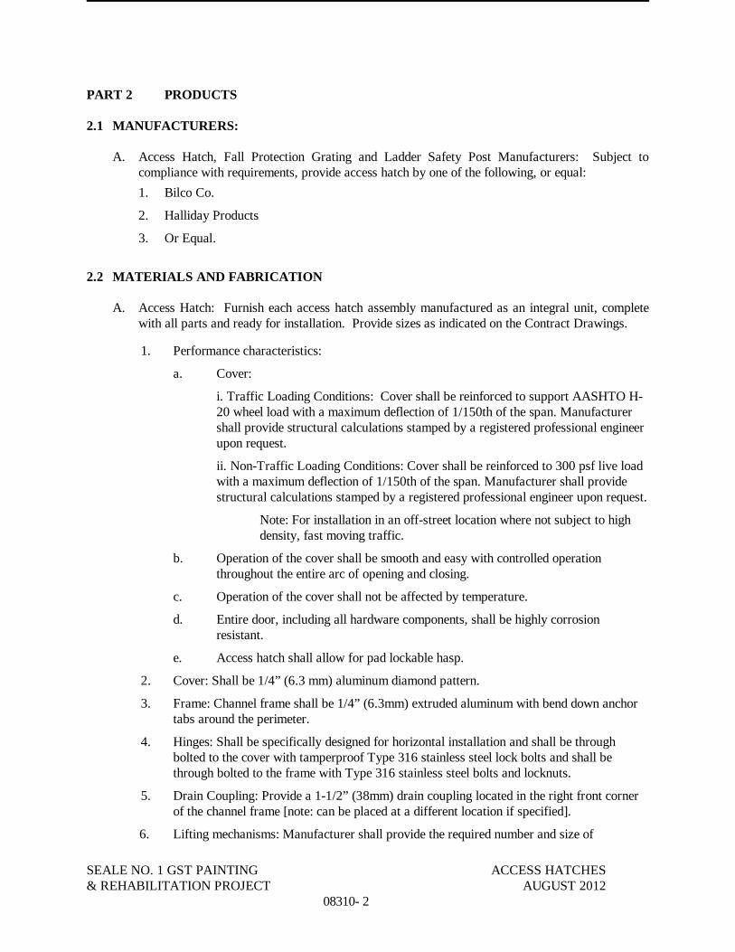
SEALE NO. 1 GST PAINTING ACCESS HATCHES& REHABILITATION PROJECT AUGUST 2012
08310- 2
PART 2 PRODUCTS
2.1 MANUFACTURERS:
A. Access Hatch, Fall Protection Grating and Ladder Safety Post Manufacturers: Subject tocompliance with requirements, provide access hatch by one of the following, or equal:
1. Bilco Co.
2. Halliday Products
3. Or Equal.
2.2 MATERIALS AND FABRICATION
A. Access Hatch: Furnish each access hatch assembly manufactured as an integral unit, completewith all parts and ready for installation. Provide sizes as indicated on the Contract Drawings.
1. Performance characteristics:
a. Cover:
i. Traffic Loading Conditions: Cover shall be reinforced to support AASHTO H-20 wheel load with a maximum deflection of 1/150th of the span. Manufacturershall provide structural calculations stamped by a registered professional engineerupon request.
ii. Non-Traffic Loading Conditions: Cover shall be reinforced to 300 psf live loadwith a maximum deflection of 1/150th of the span. Manufacturer shall providestructural calculations stamped by a registered professional engineer upon request.
Note: For installation in an off-street location where not subject to highdensity, fast moving traffic.
b. Operation of the cover shall be smooth and easy with controlled operationthroughout the entire arc of opening and closing.
c. Operation of the cover shall not be affected by temperature.
d. Entire door, including all hardware components, shall be highly corrosionresistant.
e. Access hatch shall allow for pad lockable hasp.
2. Cover: Shall be 1/4” (6.3 mm) aluminum diamond pattern.
3. Frame: Channel frame shall be 1/4” (6.3mm) extruded aluminum with bend down anchortabs around the perimeter.
4. Hinges: Shall be specifically designed for horizontal installation and shall be throughbolted to the cover with tamperproof Type 316 stainless steel lock bolts and shall bethrough bolted to the frame with Type 316 stainless steel bolts and locknuts.
5. Drain Coupling: Provide a 1-1/2” (38mm) drain coupling located in the right front cornerof the channel frame [note: can be placed at a different location if specified].
6. Lifting mechanisms: Manufacturer shall provide the required number and size of

SEALE GST NO. 1 PAINTING ACCESS HATCHES& REHABILITATION PROJECT AUGUST 2012
08310- 3
compression spring operators enclosed in telescopic tubes to provide, smooth, easy, andcontrolled cover operation throughout the entire arc of opening and to act as a check inretarding downward motion of the cover when closing. The upper tube shall be the outertube to prevent accumulation of moisture, grit, and debris inside the lower tube assembly.The lower tube shall interlock with a flanged support shoe fastened to a formed one-quarter (1/4) inch gusset support plate.
7. A removable exterior turn/lift handle with a spring loaded ball detent shall be provided toopen the cover and the latch release shall be protected by a flush, gasketed, removablescrew plug.
8. Hardware:
a. Hinges: Heavy forged Type 316 stainless steel hinges, each having a minimumone-quarter (1/4) inch (6.3 mm) diameter Type 316 stainless steel pin, shall beprovided and shall pivot so the cover does not protrude into the channel frame.
b. Cover shall be equipped with a hold open arm which automatically locks the coverin the open position.
c. Cover shall be fitted with the required number and size of compression springoperators. Springs and spring tubs shall be Type 316 stainless steel.
d. A Type 316 stainless steel snap lock with fixed handle shall be mounted on theunderside of the cover.
e. Hardware: Shall be Type 316 stainless steel throughout.
9. Finishes: Factory finish shall be mill finish aluminum with bituminous coating applied tothe exterior of the frame.
B. Ladder Safety Post: Furnish and install where indicated on plans ladder safety post. The laddersafety post shall be pre-assembled from the manufacturer.
1. Performance characteristics:
a. Tubular post shall lock automatically when fully extended.
b. Safety post shall have controlled upward and downward movement.
c. Release lever shall disengage the post to allow it to be returned to its loweredposition.
d. Post shall have adjustable mounting brackets to fit ladder rung spacing up to 14”on center and clamp brackets to accommodate ladder rungs up to 1-3/4” indiameter.
2. Post: Shall be manufactured of high strength square tubing. A pull up loop shall beprovided at the upper end of the post to facilitate raising the post.
3. Material of construction: Shall be aluminum.
4. Balancing spring: A stainless steel spring balancing mechanism shall be provided toprovide smooth, easy, controlled operation when raising and lowering the safety post.
5. Hardware: All mounting hardware shall be Type 316 stainless steel.
6. Finishes: Factory finish shall be mill finish aluminum.

SEALE NO. 1 GST PAINTING ACCESS HATCHES& REHABILITATION PROJECT AUGUST 2012
08310- 4
C. Fall Protection Grating: Furnish and install on vault access doors, where indicated on plans,fall protection grating system. Door manufacturer shall install the grating system when thedoor is fabricated or field install (by others) on existing doors already in use. If fieldinstallation is necessary, grating system shall be installed per the manufacturer’s instructions.
1. Performance characteristics:
a. Grating panel(s) shall be high visibility safety yellow in color.
b. Grating panel(s) shall lock in the fully open position.
c. Grating panel(s) shall be provided with lift assistance for ease of operation.
d. Grating system shall be UV and corrosion resistant construction with a twenty-five yearwarranty.
e. Grating panel(s) shall have a provision for locking to prevent unauthorized opening.
2. Grating: Panels shall be fiberglass, molded in one piece, with load bearing bars in bothdirections to allow for use without continuous side support. Grating shall be designed tosupport a 300 PSF live load.
3. Lift assistance: A Type 316 stainless steel torsion rod shall be incorporated into thegrating panel design to provide lift assistance when opening the grating panel.
4. Hold open feature: A Type 316 stainless steel hold open arm shall be provided to lock thecover in the fully open 90 degree position. A release handle shall be provided to allow thegrating panel to be closed.
5. Hardware: All hardware (mounting brackets, hinges, torsion rod, hold open arm, padlockloop, and fasteners) shall be Type 316 stainless steel.
PART 3 EXECUTION
3.1 INSTALLATION
A. Comply with manufacturer's instructions for installation of access hatches and ladder safetyposts.
B. Coordinate installation of work with other trades.
C. Set frames accurately in position and securely attach to supports with face panels plumb or levelin relation to adjacent finish surfaces.
D. The installer shall check as-built conditions and verify the manufacturer’s product details foraccuracy to fit the application prior to fabrication. The installer shall comply with themanufacturer’s installation instructions.
E. The manufacturer shall furnish mechanical fasteners consistent with vault access doormanufacturer’s instructions.
F. The manufacturer shall furnish fasteners necessary for installing ladder safety post on ladder.

SEALE GST NO. 1 PAINTING ACCESS HATCHES& REHABILITATION PROJECT AUGUST 2012
08310- 5
END OF SECTION

This page intentionally left blank.

SEALE GST NO. 1 PAINTING GENERAL SPECIFICATIONS& REHABILITATION PROJECT FOR COATING SYSTEMS
09800-1
SECTION 09800
GENERAL SPECIFICATIONS FOR COATING SYSTEMS
PART 1 GENERAL
1.01 SECTION INCLUDES
A. General specifications for coating systems for steel storage tanks, piping and appurtenances.
1.02 REFERENCES
A. SSPC: The Society for Protective Coatings (SSPC)
1. “Guide to Safety in Paint Application” SSPC-PA Guide 3
2. “Measurement of Dry Paint Thickness with Magnetic Gages” SSPC-PA 2
3. “Guide for Containing Debris Generated During Paint Removal Operations” SSPC-Guide 6
4. “Ferrous Metallic Abrasives” SSPC-AB 3
5. “Cleanliness of Recycled Ferrous Metallic Abrasives” SSPC-AB 2
6. “Mineral and Slag Abrasives” SSPC-AB 1
7. “Interim Guide and Visual Reference Photographs for Steel Cleaned by Water Jetting” SSPC-VIS 4(1)- 01
8. “Visual Standard for Power-and Hand-Tool Cleaned Steel” SSPC-VIS 3- 04
9. “Visual Standard for Abrasive Blast Cleaned Steel” SSPC-VIS 1- 02
10. “Guide and Reference Photographs for Steel Surfaces Prepared by Wet Abrasive SSPC-VIS 5-01
11. Steel Structures Painting Manual (Volume 1, 3rd Edition – 1993 and Volume2, 8th Edition –2000, including Commentary Section and Appendices)
B. American Water Works Association (AWWA) Standards
1. D100-05, Standard for Welded Steel Tanks for Water Storage
2. D102-011, Standard for Painting Steel Water-Storage Tanks
C. NSF International (NSF) Standard
1. ANSI/NSF Standard 61, Drinking Water System Components- Health Effects.
D. The paint manufacturer’s published product data shall be adhered to unless changed in writing bythe home office of the manufacturer.
E. Where the foregoing standards, recommendations, and specifications are conflicting, said conflictsshall be brought to the attention of the Owner.
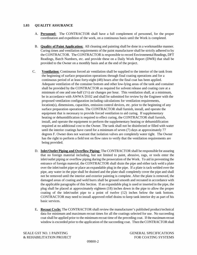
SEALE GST NO. 1 PAINTING GENERAL SPECIFICATIONS& REHABILITATION PROJECT FOR COATING SYSTEMS
09800-2
1.03 QUALITY ASSURANCE
A. Personnel: The CONTRACTOR shall have a full complement of personnel, for the propercoordination and expedition of the work, on a continuous basis until the Work is completed.
B. Quality of Paint Application: All cleaning and painting shall be done in a workmanlike manner.Curing times and ventilation requirements of the paint manufacturer shall be strictly adhered to bythe CONTRACTOR. The CONTRACTOR is responsible to record Environmental Readings, DFTReadings, Batch Numbers, etc. and provide these on a Daily Work Report (DWR) that shall beprovided to the Owner on a monthly basis and at the end of the project.
C. Ventilation: Continuous forced air ventilation shall be supplied to the interior of the tank fromthe beginning of surface preparation operations through final coating operations and for acontinuous period of at least forty-eight (48) hours after the final coat has been applied.Adequate ventilation of the container bottom and other low-lying areas of the tank and containershall be provided by the CONTRACTOR as required for solvent release and coating cure at aminimum of one and one-half (1½) air changes per hour. This ventilation shall, at a minimum,be in accordance with AWWA D102 and shall be submitted for review by the Engineer with theproposed ventilation configuration including calculations for ventilation requirements,location(s), dimensions, capacities, emission control devices, etc. prior to the beginning of anysurface preparation operations. The CONTRACTOR shall furnish, install, and operate theequipment that is necessary to provide forced ventilation to aid curing. If supplementaryheating or dehumidification is required to effect curing, the CONTRACTOR shall furnish,install, and operate the equipment to perform the supplementary heating or dehumidificationrequired at no additional cost to the Owner. The tank shall not be disinfected or filled with wateruntil the interior coatings have cured for a minimum of seven (7) days at approximately 77degrees F. Owner does not warrant that isolation valves are completely water tight. The Ownerhas the right to perform a field test on flow rates to verify that the ventilation requirements arebeing provided.
D. Inlet/Outlet Piping and Overflow Piping: The CONTRACTOR shall be responsible for assuringthat no foreign material including, but not limited to paint, abrasive, rags, or tools enter theinlet/outlet piping or overflow piping during the prosecution of the Work. To aid in preventing theentrance of foreign material, the CONTRACTOR shall drain the pipe and either tack weld a plateover the inlet/outlet pipe or place an expandable plug in the pipe. If a plate is tack welded over thepipe, any water in the pipe shall be drained and the plate shall completely cover the pipe and shallnot be removed until the interior and exterior painting is complete. After the plate is removed, thedamaged areas of coating and weld burrs shall be ground smooth and recoated in accordance withthe applicable paragraphs of this Section. If an expandable plug is used or inserted in the pipe, theplug shall be placed at approximately eighteen (18) inches down in the pipe to allow the propercoating of the inlet/outlet pipe to a point of twelve (12) inches below the tank bottom.CONTRACTOR may need to install approved relief drains to keep tank interior dry as part of hisbasic services.
E. Recoat Cycle: The CONTRACTOR shall review the manufacturer’s published product/technicaldata for minimum and maximum recoat times for all the coatings selected for use. No succeedingcoat shall be applied prior to the minimum recoat time of the preceding coat. If the maximum recoatwindow is exceeded prior to the application of the succeeding coat. Then the CONTRACTOR shall
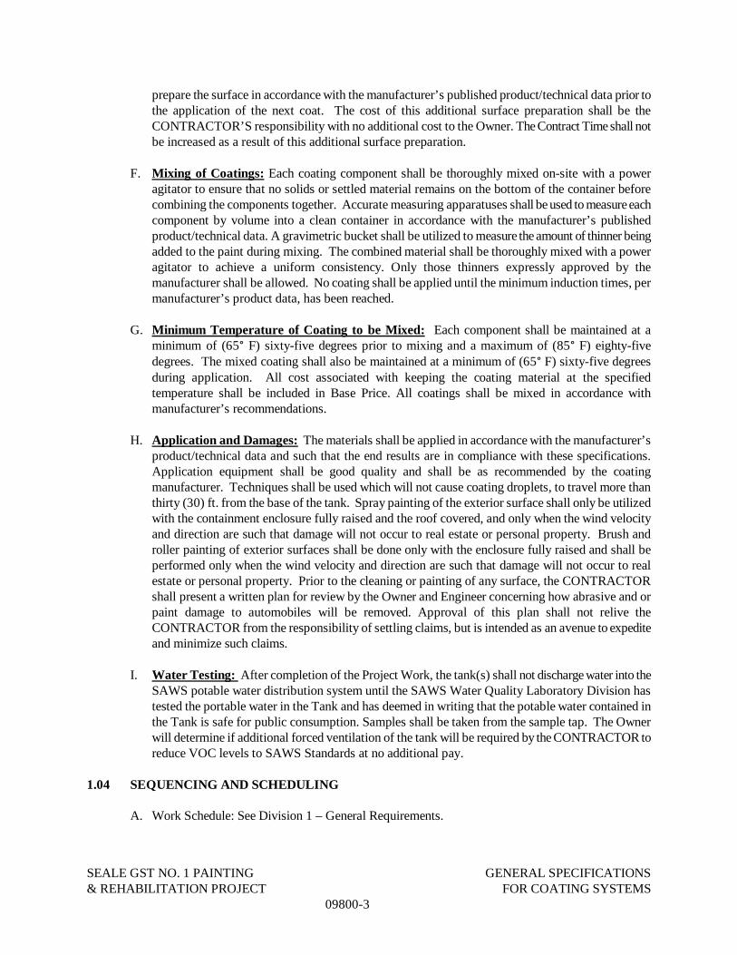
SEALE GST NO. 1 PAINTING GENERAL SPECIFICATIONS& REHABILITATION PROJECT FOR COATING SYSTEMS
09800-3
prepare the surface in accordance with the manufacturer’s published product/technical data prior tothe application of the next coat. The cost of this additional surface preparation shall be theCONTRACTOR’S responsibility with no additional cost to the Owner. The Contract Time shall notbe increased as a result of this additional surface preparation.
F. Mixing of Coatings: Each coating component shall be thoroughly mixed on-site with a poweragitator to ensure that no solids or settled material remains on the bottom of the container beforecombining the components together. Accurate measuring apparatuses shall be used to measure eachcomponent by volume into a clean container in accordance with the manufacturer’s publishedproduct/technical data. A gravimetric bucket shall be utilized to measure the amount of thinner beingadded to the paint during mixing. The combined material shall be thoroughly mixed with a poweragitator to achieve a uniform consistency. Only those thinners expressly approved by themanufacturer shall be allowed. No coating shall be applied until the minimum induction times, permanufacturer’s product data, has been reached.
G. Minimum Temperature of Coating to be Mixed: Each component shall be maintained at aminimum of (65° F) sixty-five degrees prior to mixing and a maximum of (85° F) eighty-fivedegrees. The mixed coating shall also be maintained at a minimum of (65° F) sixty-five degreesduring application. All cost associated with keeping the coating material at the specifiedtemperature shall be included in Base Price. All coatings shall be mixed in accordance withmanufacturer’s recommendations.
H. Application and Damages: The materials shall be applied in accordance with the manufacturer’sproduct/technical data and such that the end results are in compliance with these specifications.Application equipment shall be good quality and shall be as recommended by the coatingmanufacturer. Techniques shall be used which will not cause coating droplets, to travel more thanthirty (30) ft. from the base of the tank. Spray painting of the exterior surface shall only be utilizedwith the containment enclosure fully raised and the roof covered, and only when the wind velocityand direction are such that damage will not occur to real estate or personal property. Brush androller painting of exterior surfaces shall be done only with the enclosure fully raised and shall beperformed only when the wind velocity and direction are such that damage will not occur to realestate or personal property. Prior to the cleaning or painting of any surface, the CONTRACTORshall present a written plan for review by the Owner and Engineer concerning how abrasive and orpaint damage to automobiles will be removed. Approval of this plan shall not relive theCONTRACTOR from the responsibility of settling claims, but is intended as an avenue to expediteand minimize such claims.
I. Water Testing: After completion of the Project Work, the tank(s) shall not discharge water into theSAWS potable water distribution system until the SAWS Water Quality Laboratory Division hastested the portable water in the Tank and has deemed in writing that the potable water contained inthe Tank is safe for public consumption. Samples shall be taken from the sample tap. The Ownerwill determine if additional forced ventilation of the tank will be required by the CONTRACTOR toreduce VOC levels to SAWS Standards at no additional pay.
1.04 SEQUENCING AND SCHEDULING
A. Work Schedule: See Division 1 – General Requirements.

SEALE GST NO. 1 PAINTING GENERAL SPECIFICATIONS& REHABILITATION PROJECT FOR COATING SYSTEMS
09800-4
B. Cleaning Areas of Welding and/or Grinding: See Division 1- General Requirements.
1.05 SUBMITTALS
A. Submit sets to the Engineer in accordance with Section 01300 - Submittals.
1. Product Data:
a. Written description and catalog cuts describing each type of proposed abrasive for theinterior and exterior surfaces. Include technical data sheets to substantiate compliancewith specifications.
b. Written description and catalog cuts describing each coating in the system. Informationshall include: product delivery, storage, handling, application and curing instructions andlimitations. Include technical data sheets to substantiate compliance with specifications.This shall include, but is not limited, to the following: surface preparation, methods ofapplication, thickness of each coat, time (minimum and maximum) between coats, propermixing prior to application, weather limitations drying and after application, physicalproperties of coating (percent solids), equipment settings and pot life at varioustemperatures and humidity.
c. Written description and catalog cuts describing each thinner proposed for use with eachcoating system. Also include solvent or thinner for use in cleaning paint equipment.Include technical data sheets to substantiate compliance with specifications.
d. Written description and catalog cuts describing the proposed underwater curing epoxypaint for the interior surfaces at the First Anniversary Inspection. Include technical datasheets to substantiate compliance with specifications.
2. Certification:
a. Provide certification signed by the supplier of the coating attesting that the coating systemproposed meets the specifications.
b. Provide certification from the manufacturer that all coatings will not contain more than0.06% by weight of lead in the cured coating for each coat applied. Certification shall besubmitted to the Engineer.
3. Cleanup Procedures: Prior to the field cleaning or painting of any surface, theCONTRACTOR shall present a written plan to the Owner and Engineer for review concerninghow paint and/or abrasive damage to automobiles and property will be handled, including aprocess for quick removal of the paint or abrasive, and who will do the work. This approval inno way shall relieve the contractor from the responsibility of settling claims for damage, but isintended as an avenue to expedite and minimize said claims.
4. Containment Procedures: Prior to the field cleaning or painting of any surface, theCONTRACTOR shall present a written plan to the Owner and Engineer for review concerninghow spent cleaning debris and paint over spray or droplets will be contained and confined to thejobsite and tank site during the surface preparation and coating application operations.Reasonable care shall be exercised by the CONTRACTOR to prevent damage, nuisance, orhazardous conditions to adjacent or nearby property owners.
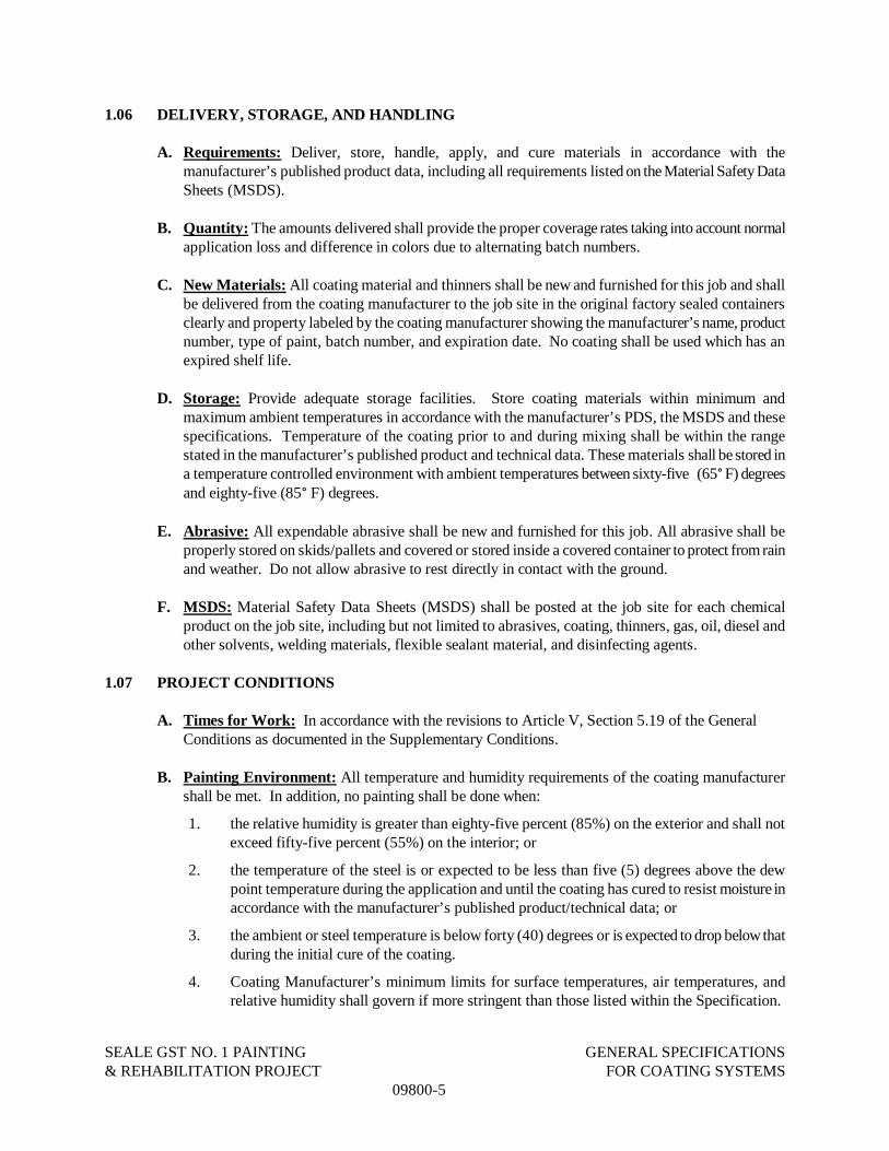
SEALE GST NO. 1 PAINTING GENERAL SPECIFICATIONS& REHABILITATION PROJECT FOR COATING SYSTEMS
09800-5
1.06 DELIVERY, STORAGE, AND HANDLING
A. Requirements: Deliver, store, handle, apply, and cure materials in accordance with themanufacturer’s published product data, including all requirements listed on the Material Safety DataSheets (MSDS).
B. Quantity: The amounts delivered shall provide the proper coverage rates taking into account normalapplication loss and difference in colors due to alternating batch numbers.
C. New Materials: All coating material and thinners shall be new and furnished for this job and shallbe delivered from the coating manufacturer to the job site in the original factory sealed containersclearly and property labeled by the coating manufacturer showing the manufacturer’s name, productnumber, type of paint, batch number, and expiration date. No coating shall be used which has anexpired shelf life.
D. Storage: Provide adequate storage facilities. Store coating materials within minimum andmaximum ambient temperatures in accordance with the manufacturer’s PDS, the MSDS and thesespecifications. Temperature of the coating prior to and during mixing shall be within the rangestated in the manufacturer’s published product and technical data. These materials shall be stored ina temperature controlled environment with ambient temperatures between sixty-five (65° F) degreesand eighty-five (85° F) degrees.
E. Abrasive: All expendable abrasive shall be new and furnished for this job. All abrasive shall beproperly stored on skids/pallets and covered or stored inside a covered container to protect from rainand weather. Do not allow abrasive to rest directly in contact with the ground.
F. MSDS: Material Safety Data Sheets (MSDS) shall be posted at the job site for each chemicalproduct on the job site, including but not limited to abrasives, coating, thinners, gas, oil, diesel andother solvents, welding materials, flexible sealant material, and disinfecting agents.
1.07 PROJECT CONDITIONS
A. Times for Work: In accordance with the revisions to Article V, Section 5.19 of the GeneralConditions as documented in the Supplementary Conditions.
B. Painting Environment: All temperature and humidity requirements of the coating manufacturershall be met. In addition, no painting shall be done when:
1. the relative humidity is greater than eighty-five percent (85%) on the exterior and shall notexceed fifty-five percent (55%) on the interior; or
2. the temperature of the steel is or expected to be less than five (5) degrees above the dewpoint temperature during the application and until the coating has cured to resist moisture inaccordance with the manufacturer’s published product/technical data; or
3. the ambient or steel temperature is below forty (40) degrees or is expected to drop below thatduring the initial cure of the coating.
4. Coating Manufacturer’s minimum limits for surface temperatures, air temperatures, andrelative humidity shall govern if more stringent than those listed within the Specification.

SEALE GST NO. 1 PAINTING GENERAL SPECIFICATIONS& REHABILITATION PROJECT FOR COATING SYSTEMS
09800-6

SEALE GST NO. 1 PAINTING GENERAL SPECIFICATIONS& REHABILITATION PROJECT FOR COATING SYSTEMS
09800-7
C. Humidity and Temperature Measuring Equipment: The CONTRACTOR shall have dry–bulbwet-bulb measuring equipment and steel temperature measuring equipment on the job at all times.Readings shall be measured at the beginning and at the end of each painting session and at intervalsof two hours or less. Note: The CONTRACTOR is required to perform these duties and provide allreadings to the Owner on a monthly basis and at the end of the project.
D. Wind Velocity: Wind velocities during the exterior painting shall be compatible for the qualityapplication of the exterior coatings and in compliance with local regulatory requirements. Whenpainting exterior surfaces, wind direction and velocity shall be considered. Exterior paintapplications shall cease when wind velocities reach twenty-five (25) miles an hour or more, either ingusts or at a steady state. The CONTRACTOR shall utilize all necessary precautions to preventundue dispersing of materials outside the work area.
E. Safety and Health: Safety of all personnel is the CONTRACTOR’S responsibility; refer toSection 01060 – Regulatory Requirements.
F. Rigging Attachments: See Section 01060 – Regulatory Requirements.
G. Containing Cleaning Debris and Overspray: The CONTRACTOR shall ensure that no spentcleaning/blasting debris, dust, overspray, coating droplets, or emissions of any kind, escape to theatmosphere, the base of the tank, or adjacent buildings, private property, work sites and parking lots.
1. For all surface preparation, clean up, debris removal and painting application work of the tank,the containment system shall at a minimum meet the emission control requirements of a Class2A System, as specified in Section 4.2.2.2 of the SSPC-Guide 6 (CON), Guide for ContainingDebris Generated during Paint Removal Operations, (Latest Edition). The groundsurrounding the tank shall be protected from all debris, emissions, dust, and other materialsgenerated in the cleaning operations with a minimum of two layers of polyethylene covered withplywood or the same material used for the perimeter containment system.
2. The CONTRACTOR shall be responsible for all materials that are used and for any apparatusused to contain dust, emissions, debris, overspray, and coating droplets. The containmentsystem and attachments to the tank shall be designed by a Professional Engineerregistered in the State of Texas. The CONTRACTOR shall submit the signed and sealedengineering design including details of the containment system for the tank. This informationshall include drawings, equipment specifications, and calculations for wind load, air flow and.The containment system will NOT place additional loads on the tank that the tank was notoriginally designed for. The CONTRACTOR shall reinforce the tank as necessary to preventpermanent deformation and to assure that no damage occurs to the tank. Any damage to thetank as a direct or indirect result of the containment system shall be repaired or sections replacedby the CONTRACTOR at no additional cost to the Owner. Neither the Owner nor the Engineerassumes any responsibility for the structural ability of the tank to support the containmentsystem.
3. If complete containment of the tank is utilized to contain all cleaning dust, debris, emissions,paint droplets, and paint overspray, the complete containment shall include a full roofbonnet.
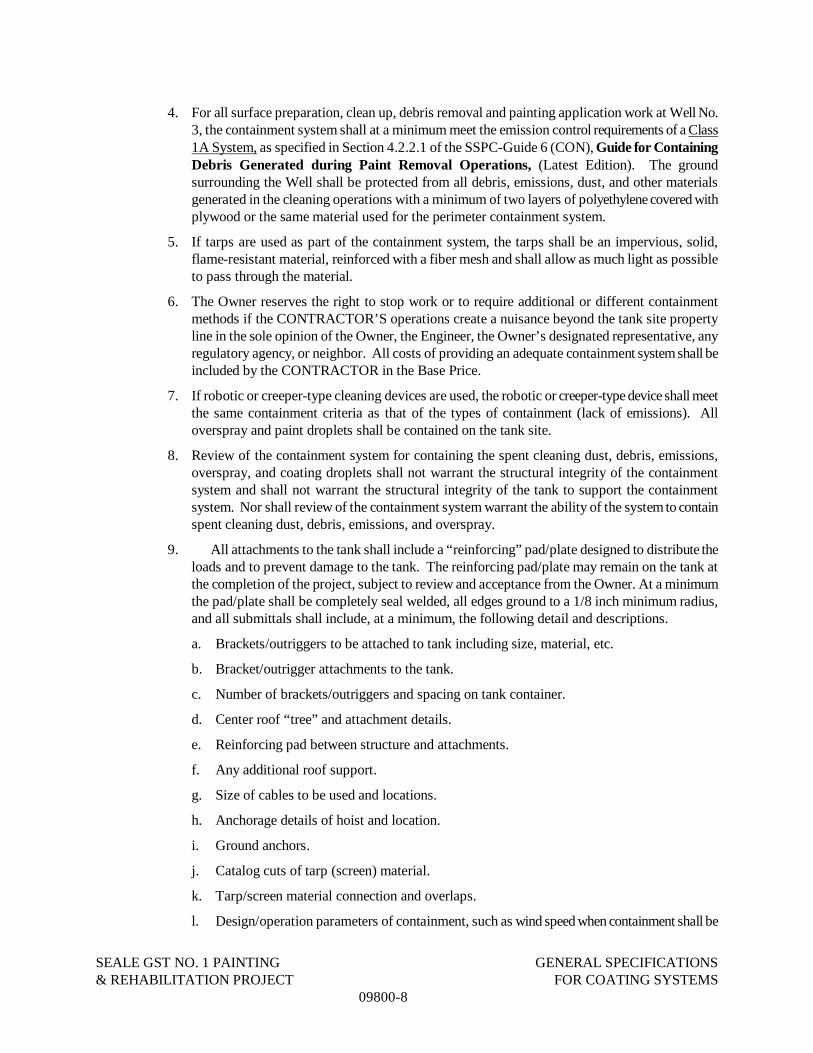
SEALE GST NO. 1 PAINTING GENERAL SPECIFICATIONS& REHABILITATION PROJECT FOR COATING SYSTEMS
09800-8
4. For all surface preparation, clean up, debris removal and painting application work at Well No.3, the containment system shall at a minimum meet the emission control requirements of a Class1A System, as specified in Section 4.2.2.1 of the SSPC-Guide 6 (CON), Guide for ContainingDebris Generated during Paint Removal Operations, (Latest Edition). The groundsurrounding the Well shall be protected from all debris, emissions, dust, and other materialsgenerated in the cleaning operations with a minimum of two layers of polyethylene covered withplywood or the same material used for the perimeter containment system.
5. If tarps are used as part of the containment system, the tarps shall be an impervious, solid,flame-resistant material, reinforced with a fiber mesh and shall allow as much light as possibleto pass through the material.
6. The Owner reserves the right to stop work or to require additional or different containmentmethods if the CONTRACTOR’S operations create a nuisance beyond the tank site propertyline in the sole opinion of the Owner, the Engineer, the Owner’s designated representative, anyregulatory agency, or neighbor. All costs of providing an adequate containment system shall beincluded by the CONTRACTOR in the Base Price.
7. If robotic or creeper-type cleaning devices are used, the robotic or creeper-type device shall meetthe same containment criteria as that of the types of containment (lack of emissions). Alloverspray and paint droplets shall be contained on the tank site.
8. Review of the containment system for containing the spent cleaning dust, debris, emissions,overspray, and coating droplets shall not warrant the structural integrity of the containmentsystem and shall not warrant the structural integrity of the tank to support the containmentsystem. Nor shall review of the containment system warrant the ability of the system to containspent cleaning dust, debris, emissions, and overspray.
9. All attachments to the tank shall include a “reinforcing” pad/plate designed to distribute theloads and to prevent damage to the tank. The reinforcing pad/plate may remain on the tank atthe completion of the project, subject to review and acceptance from the Owner. At a minimumthe pad/plate shall be completely seal welded, all edges ground to a 1/8 inch minimum radius,and all submittals shall include, at a minimum, the following detail and descriptions.
a. Brackets/outriggers to be attached to tank including size, material, etc.
b. Bracket/outrigger attachments to the tank.
c. Number of brackets/outriggers and spacing on tank container.
d. Center roof “tree” and attachment details.
e. Reinforcing pad between structure and attachments.
f. Any additional roof support.
g. Size of cables to be used and locations.
h. Anchorage details of hoist and location.
i. Ground anchors.
j. Catalog cuts of tarp (screen) material.
k. Tarp/screen material connection and overlaps.
l. Design/operation parameters of containment, such as wind speed when containment shall be

SEALE GST NO. 1 PAINTING GENERAL SPECIFICATIONS& REHABILITATION PROJECT FOR COATING SYSTEMS
09800-9
lowered or not used.
m. Ground cover, material. etc.
n. Other dust collection and engineering controls.
o. Any item desired to be left on the tank structure at the completion of the Project (subject toapproval by the Owner).
p. Maximum wind velocity which the containment system can remain raised and the procedurefor which the containment system will be utilized on forecasted high/gusty wind days.
10. Overspray Plan: CONTRACTOR shall submit a written plan to the Owner describing measuresthat will be taken to prevent over-sprays and how the CONTRACTOR will deal with over-sprays should they occur. The CONTRACTOR shall acknowledge in this submittal that anydamage caused by over-sprays to SAWS property and adjacent properties shall be theresponsibility of the CONTRACTOR.
11. Visible Emissions: The CONTRACTOR shall conduct observations of visible emissions andreleases on an ongoing daily basis when dust producing activities are underway, such as paintremoval, clean up, waste handling and containment dismantling or relocation. Visible emissionsin excess of SSPC Guide 6, Level 1 (1% of the workday) shall be deemed unacceptable. Thisequates to 300 sec. or 5 minutes in an 8 hr. shift. This criterion applies to random, scatteredemissions of short duration. Sustained emissions from a given location (that last 1 minute orlonger), regardless of total length of emissions for a workday, are unacceptable and action shallbe initiated to halt the emission. Should unacceptable visible emissions or releases be observed,the CONTRACTOR shall immediately shutdown the emission producing activity, clean up thedebris generated, change work procedures if necessary, modify the containment and/or takeother appropriate corrective action as needed to prevent similar releases from occurring in thefuture.
H. Dust Collection: CONTRACTOR shall furnish, operate, and maintain adequate dust collectionduring the Project to achieve negative pressure within the containment or adequate air flow withinthe tank interior. The dust collection system shall at a minimum meet the requirements of a Type J1Air Filtration system, as specified in Section 5.4.5.1 of the SSPC-Guide 6 (CON), Guide forcontaining Debris Generated During Paint Removal Operations, current revisions. The dustcollection shall be operated during all abrasive blast cleaning and until the area is clean enough forcoating application. The CONTRACTOR shall be responsible for all sizing, design of ductwork,etc., based upon the Contractor’s operations, number of blasters, duration of blasting, etc. TheCONTRACTOR is responsible to come as close as practical to the target velocities of 100 ft/mincross draft or 60 ft/min downdraft. The CONTRACTOR shall also take precautions to avoid avacuum from developing inside the tank, as even a slight vacuum inside of the tank may causedamage to the tank. Dust Socks are not permitted.
I. Attractive Nuisances and Cleanup: See Section 01040 – Coordination.
J. Dehumidification: See Section 09872 – Interior Coating System for Steel Storage Tank.

SEALE GST NO. 1 PAINTING GENERAL SPECIFICATIONS& REHABILITATION PROJECT FOR COATING SYSTEMS
09800-10
1.08 ENVIRONMENTAL REGULATIONS AND WORKER PROTECTION
A. See Section 01060 – Regulatory Requirements.
1.09 FIRST ANNIVERSARY INSPECTION
A. Requirements: A First Anniversary Inspection shall be performed by the CONTRACTOR. TheContractor’s Performance Bond or separate Maintenance Bond shall be in force until after remedialwork is performed. The Performance of this inspection and /or any remedial work shall not relievethe CONTRACTOR of any responsibility for defects in materials or workmanship which may ormay not be evident during the First Anniversary Inspection. The inspection shall be performed asclose to the twelve month period as possible.
B. AWWA D102: The First Anniversary Inspection as described in Section 5.2 of AWWA D102 shallapply.
C. Inspection: The CONTRACTOR shall perform the following duties at the First AnniversaryInspection:
1. The CONTRACTOR shall be present for the inspection, shall furnish an experienced foreman,laborer, rigging and assistance for the inspection.
2. The CONTRACTOR shall completely washout the interior of the container for the one yearevaluation. All debris from the interior of the container shall be legally disposed of by theCONTRACTOR at no additional cost of the Owner.
3. The CONTRACTOR shall be prepared to perform minor touch-up operations.
4. The CONTRACTOR shall have at least a one gallon kit of Aquatapoxy Paint (manufactured byRaven Lining Systems) to touch-up the interior surfaces. If more than a one gallon kit is needed,then the specified epoxy shall be used to touch-up the interior surfaces.
5. The CONTRACTOR shall have at least one gallon of each of the exterior and interior primers,intermediate coatings, and finish coatings at the time of the inspection along with powercleaning tools and abrasive disks for spot cleaning.
6. All costs associated with the First Anniversary Inspection shall be included in the Base Price.
7. Spot repairs shall be made by the CONTRACTOR prior to returning the tank back into service. Repairs requiring extensive work and rigging may be delayed until a time mutually agreeable tothe Owner and CONTRACTOR.
8. The CONTRACTOR shall disinfect the tank in accordance with Section 02675 – Disinfectionof Water Distribution System until two consecutive satisfactory water samples are reportedfrom the Owner’s Laboratory.
9. Failure of the Owner to establish a date for the First Anniversary Inspection shall/will notrelieve the CONTRACTOR of the responsibility to repair the interior and exterior coatingsystem.
10. If failures in any portion of the tank exceed five (5) percent of that portion (surface), asdetermined by the Owner, then those areas the entire coating system shall be removed andreapplied. Defects of the coating system are considered but are not limited to: bubbles, blisters,chipped or cracked paint, holidays/pinholes etc.

SEALE GST NO. 1 PAINTING GENERAL SPECIFICATIONS& REHABILITATION PROJECT FOR COATING SYSTEMS
09800-11
11. CONTRACTOR will be responsible for placing the cathodic protection system in operation andproviding a certification from the manufacturer’s representative that it is properly installed andcalibrated.
PART 2 PRODUCTS
2.01 MATERIALS
A. Abrasive: The approved abrasive for cleaning shall meet the following requirements:
1. The exterior cleaning methods and the type of abrasive used shall comply with the requirementsof the Texas Commission of Environmental Quality (TCEQ) Regulations, “Abrasive Blastingof Water Storage Tanks Performed by Portable Operations”; Title 30; Part 1; Chapter 111;Subchapter A; Division 3.
2. All expendable abrasives shall meet the minimum requirements of SSPC-AB 1 and all abrasivesshall meet the requirements of Class A (of SSPC-AB 1) for silica content (less than 1%crystalline silica by weight before blasting.)
3. The abrasive shall be of a grit size to produce a 1.5 mil to 3.5 mil profile. If the profile exceedsthis range, then the prime coat dry mil thickness shall be increased by the difference betweenthe actual profile and the specified profile to prevent the peaks in the profile from rusting. Themaximum coating thickness applied shall remain in accordance with the manufacturer’spublished product/technical data.
4. The abrasive shall be free from contaminates, such as excessive fine particles, regulated heavymetals, paint, earth, oil, clay, moisture, or chlorides, which can cause premature coating failures.
5. Use of abrasive on the tank and structure shall be based not only on its compliance with thetechnical application of the coatings, but also on its lack of nuisance to the surroundingproperty.
6. The abrasive blasting of the interior surfaces shall be done with a commercially available, non-metallic, expendable abrasive or a re-usable abrasive (steel grit).
7. The abrasive blasting of the exterior surfaces shall be done by shrouded abrasive blasting with acommercially available, non-metallic, expendable abrasive, or vacuum blasting with a re-usableabrasive (steel grit).
8. The steel grit shall meet the requirements of SSPC-AB 3, Newly Manufactured or Re-Manufactured Steel Abrasives, and must be approved for use by the manufacturer of theblasting, media recovery, and separation equipment. The initial quality of grit shall consist ofan artificial working mix determined by the CONTRACTOR to produce an acceptable profile inaccordance with these specifications. Any steel grit used on this Project shall be sampled beforeuse by the CONTRACTOR in the presence of the Field Inspector and have the samples sent to alaboratory for atomic absorption testing for total lead. The steel grit shall not be used until theresults of the atomic absorption testing are submitted to the Owner and indicate that the totallead levels are less than 1,000 ppm (<0.1%).
10. The CONTRACTOR shall provide the Owner with the MSDS for the abrasive being used.

SEALE GST NO. 1 PAINTING GENERAL SPECIFICATIONS& REHABILITATION PROJECT FOR COATING SYSTEMS
09800-12
B. Blast Media Recovery and Separation System:
1. Equipment Requirements: The equipment provided for the spent abrasive recovery and mediaseparation shall be a portable commercial recycling abrasive blast machine. The re-usedabrasive shall comply with the requirements of SSPC-AB 2, Specification for Cleanliness ofRecycled Ferrous Metallic Abrasives. The system shall be capable of recovering the abrasive,and returning the spent cleaning debris to a dust separator which shall be an integrated part ofthe machine. The waste material shall be placed in container drums in accordance with theRemoval and Disposal of Cleaning Residue paragraph in this specification.
2. Equipment Characteristics: At a minimum, the vacuum system used to recover the spentblasting material shall contain the following:
a. A double-chambered ASME pressure vessel, which can effectively recycle blast media on acontinuous basis.
b. A dust filter back flushing system.
c. An air drying system consisting of an air-cooled after cooler, sling separator, and desiccantdrier.
C. Approval of Coatings: All coatings shall be acceptable to the United States EPA, TCEQ, and othercontrolling local health and environmental regulatory agencies. All interior coating materials,solvents, and other additives shall comply with ANSI/NSF Standard 61. All coatings to be usedshall be listed as to manufacturer and number or description on the “LISTING OF SUPPLIERS”,which shall be standards of quality. Alternate coatings, materials and manufacturers will only beconsidered after award of the Contract in accordance with the Instructions to Respondents.
D. Common Manufacturer: The interior and exterior coatings shall be furnished by the samemanufacturer unless specifically stated otherwise in these Specifications.
E. Lead and Other Heavy Metal Restrictions in Coatings: Coatings which contain more than 0.06%by weight of lead (or other lead compounds), cadmium, or chromium in the cured coating for eachcoat applied shall not be used.
F. Thinners: Thinners shall be used only in accordance with the manufacturer’s publishedproduct/technical data. Only thinners recommended and furnished by the coating manufacturer shallbe used for this project.
G. Underwater Epoxy: The approved underwater curing epoxy paint shall be 100% solids materialand shall cure underwater. The approved underwater curing epoxy paint shall be acceptable to theUSEPA, TCEQ, NSF and/or other controlling local environmental and health regulatory agencies.
PART 3 EXECUTION
3.01 VERIFICATION OF CONDITIONS
A. Before applications of the coating materials, verify that specified procedures and products willprovide adequate protection of the steel substrates.
3.02 PROTECTION
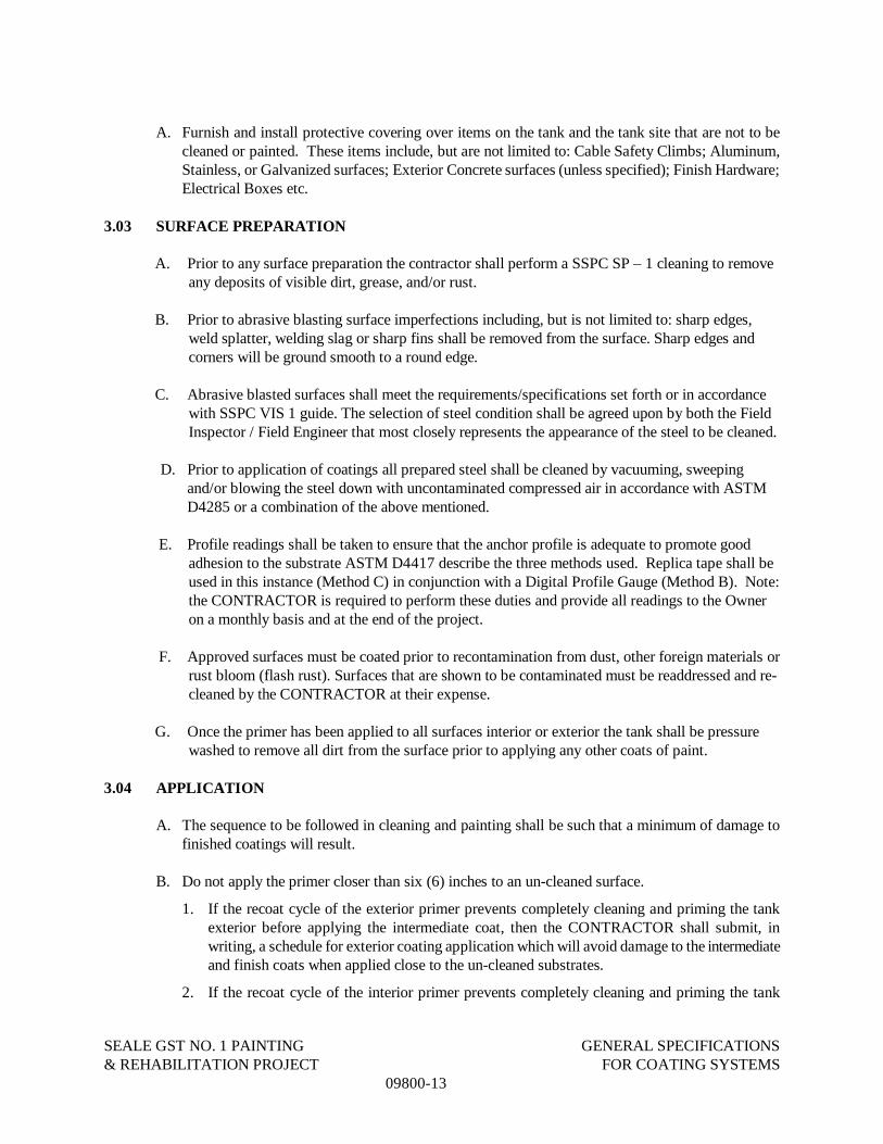
SEALE GST NO. 1 PAINTING GENERAL SPECIFICATIONS& REHABILITATION PROJECT FOR COATING SYSTEMS
09800-13
A. Furnish and install protective covering over items on the tank and the tank site that are not to becleaned or painted. These items include, but are not limited to: Cable Safety Climbs; Aluminum,Stainless, or Galvanized surfaces; Exterior Concrete surfaces (unless specified); Finish Hardware;Electrical Boxes etc.
3.03 SURFACE PREPARATION
A. Prior to any surface preparation the contractor shall perform a SSPC SP – 1 cleaning to removeany deposits of visible dirt, grease, and/or rust.
B. Prior to abrasive blasting surface imperfections including, but is not limited to: sharp edges,weld splatter, welding slag or sharp fins shall be removed from the surface. Sharp edges andcorners will be ground smooth to a round edge.
C. Abrasive blasted surfaces shall meet the requirements/specifications set forth or in accordancewith SSPC VIS 1 guide. The selection of steel condition shall be agreed upon by both the FieldInspector / Field Engineer that most closely represents the appearance of the steel to be cleaned.
D. Prior to application of coatings all prepared steel shall be cleaned by vacuuming, sweepingand/or blowing the steel down with uncontaminated compressed air in accordance with ASTMD4285 or a combination of the above mentioned.
E. Profile readings shall be taken to ensure that the anchor profile is adequate to promote goodadhesion to the substrate ASTM D4417 describe the three methods used. Replica tape shall beused in this instance (Method C) in conjunction with a Digital Profile Gauge (Method B). Note:the CONTRACTOR is required to perform these duties and provide all readings to the Owneron a monthly basis and at the end of the project.
F. Approved surfaces must be coated prior to recontamination from dust, other foreign materials orrust bloom (flash rust). Surfaces that are shown to be contaminated must be readdressed and re-cleaned by the CONTRACTOR at their expense.
G. Once the primer has been applied to all surfaces interior or exterior the tank shall be pressurewashed to remove all dirt from the surface prior to applying any other coats of paint.
3.04 APPLICATION
A. The sequence to be followed in cleaning and painting shall be such that a minimum of damage tofinished coatings will result.
B. Do not apply the primer closer than six (6) inches to an un-cleaned surface.
1. If the recoat cycle of the exterior primer prevents completely cleaning and priming the tankexterior before applying the intermediate coat, then the CONTRACTOR shall submit, inwriting, a schedule for exterior coating application which will avoid damage to the intermediateand finish coats when applied close to the un-cleaned substrates.
2. If the recoat cycle of the interior primer prevents completely cleaning and priming the tank

SEALE GST NO. 1 PAINTING GENERAL SPECIFICATIONS& REHABILITATION PROJECT FOR COATING SYSTEMS
09800-14
interior before applying the finish coat, then the CONTRACTOR shall submit, in writing, aschedule for interior coating application which will avoid damage to the finish coat when appliedclose to the un-cleaned substrates.
3.05 TOLERENCES
A. Coating Thickness:
1. The thickness of each type coating is essential to the system’s integrity.
2. Dry mil thickness greater than the coating manufacturer’s maximum allowable thickness shallbe considered unacceptable and shall be removed by the CONTRACTOR at no additional costto the Owner at the direction of the Owner and Field Inspector.
3. The additional of mils in a succeeding coat of a different generic type or formulation to make upfor thin preceding coat(s) shall not be allowed. If a thicker finish coat is needed to hide thedarker color of the underlying coat on the exterior of the tank, a thicker coat may be applied, butit shall not exceed the maximum allowable thickness recommended by the coating manufacturer.
4. Coating thickness measurement procedures shall be as outlined in SSPC-PA2.
5. The CONTRACTOR shall document readings and provide these readings to the Owner on amonthly basis and at the end of the project in their QA Reports.
6. If determined to be in the best interest of the project, the Field Inspector may make dry filmmeasurements in excess of the amount prescribed in the SSPC-PA 2.
3.06 OBSERVATION
A. Accessibility for Observation:
1. Notification: The Engineer and Field Inspector shall be notified 7 days, and confirmed 24hours, prior to the start of any cleaning or painting operations of the steel.
2. Accessibility for Observation: All work shall be made accessible to the Field Inspector andEngineer using the CONTRACTOR’S rigging and equipment. The CONTRACTOR shallinclude all labor necessary to assist the Field Inspector and Engineer in accessing the work to beobserved.
3. CONTRACTOR Supervision: The CONTRACTOR is to supervise the job properly at alltimes.
4. Observation: The Owner reserves the right to engage full-time observation services, or toperform observations intermittently.
B. Observation Schedule:
1. Notification: The CONTRACTOR shall notify and make available to the Filed Inspector andEngineer for observation all surfaces prior to the application of each coat of paint.
2. Curing: The interior wet area coating shall be completely cured and the solvents shall beadequately released and the tank shall not be filled with water until observed by the Owner andthe Filed Inspector. The exterior coating on the opposite side of the water bearing surfaces shallbe completely cured and the tank shall not be filled with water until observed by the Owner andFiled Inspector.

SEALE GST NO. 1 PAINTING GENERAL SPECIFICATIONS& REHABILITATION PROJECT FOR COATING SYSTEMS
09800-15
3. Holiday Testing: All interior wet coatings, including those above the high water line/level, shallbe tested with a wet sponge low voltage holiday detector in accordance with AWWA D 102-11in the presence of the Filed Inspector and a SAWS Engineer. Any holidays, pinholes, or voidsindicated shall be repaired by applying more of the coating by brush or roller. The areas shall beretested after the appropriate curing time. Following the application of the Intermediate Coat theinterior coating system will be 100% holiday tested. Following the application of the FinishCoat the interior coating system will be 75% holiday tested.
3.07 CLEANING
A. CONTRACTOR Performed Cleanup: Site cleanup shall be provided by the CONTRACTOR on adaily, ongoing basis. Upon completion of the Work, the jobsite shall be left clean of all debris,blasting abrasive, or any other items resulting from the operations of the CONTRACTOR. Anyasphalt paving damaged by the CONTRACTOR’S operations shall be replaced to new condition bythe CONTRACTOR at no additional cost to the Owner.
B. Owner Performed Cleanup: The cost of any cleanup which must be done by the Owner will bededucted from funds due the CONTRACTOR.
C. Piping: Any material found in the inlet/outlet, drain, or overflow piping as a result of theCONTRACTOR’S operations at the time the tank is placed back into service shall be removed at theexpense of the CONTRACTOR.
D. Tank Disinfection: Wash and disinfect the tank in accordance with Section 13220– Disinfection ofWater Distribution Systems.
END OF SECTION
SEALE GST NO. 1 PAINTING EXTERIOR COATING SYSTEM& REHABILITATION PROJECT FOR STEEL STORAGE TANK
09871-1 AUGUST 2012
SECTION 09871
EXTERIOR COATING SYSTEM FOR STEEL STORAGE TANKS
PART 1 GENERAL
1.01 SECTION INCLUDES
A. The exterior surfaces included are all exterior surfaces of the tank, including but not limited to:1. the reservoir/container;2. wind girder;3. all inlet/outlet and overflow piping appurtenances;4. vents, manholes, ladders, platforms; and5. bolts, threads, nuts, pins, brackets, seams, corners, knife edges, welds, etc.
B. Specifications for the coating of the exterior surfaces of existing steel water storage tanks.
C. Preparations of all exterior surfaces which are to receive coating are included in this Section.
D. Paintings of all exterior surfaces which are to receive coating are included in this Section.
E. Exterior primers, intermediate, and finish coats for steel water storage tanks.
1.02 RELATED SECTIONS
A. Section 09800 – General Specifications Coating Systems
PART 2 PRODUCTS
2.01 MATERIALS AND MANUFACTURERS
A. Coating Schedule: Acceptable coating manufacturers and specifications for the exterior surfaces ofsteel water storage tanks follow; however, the CONTRACTOR is advised that all manufacturerspresented below must submit and certify that the coatings furnished are in compliance with theseSpecifications and the Manufacturer’s Recommendations.
Exterior Coating System to be of the same Manufacturer of all other coating products used on thisproject.
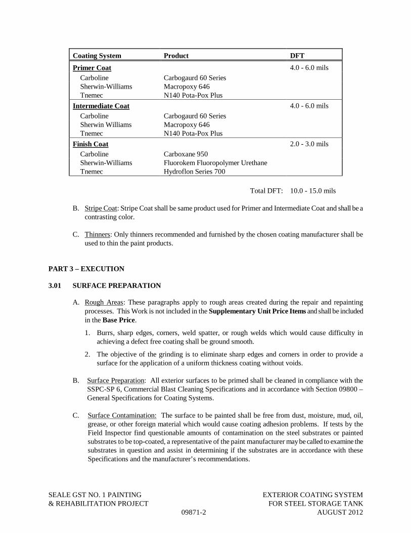
SEALE GST NO. 1 PAINTING EXTERIOR COATING SYSTEM& REHABILITATION PROJECT FOR STEEL STORAGE TANK
09871-2 AUGUST 2012
Coating System Product DFT
Primer Coat 4.0 - 6.0 milsCarboline Carbogaurd 60 SeriesSherwin-WilliamsTnemec
Macropoxy 646N140 Pota-Pox Plus
Intermediate Coat 4.0 - 6.0 milsCarboline Carbogaurd 60 SeriesSherwin WilliamsTnemec
Macropoxy 646N140 Pota-Pox Plus
Finish Coat 2.0 - 3.0 milsCarboline Carboxane 950Sherwin-WilliamsTnemec
Fluorokem Fluoropolymer UrethaneHydroflon Series 700
Total DFT: 10.0 - 15.0 mils
B. Stripe Coat: Stripe Coat shall be same product used for Primer and Intermediate Coat and shall be acontrasting color.
C. Thinners: Only thinners recommended and furnished by the chosen coating manufacturer shall beused to thin the paint products.
PART 3 – EXECUTION
3.01 SURFACE PREPARATION
A. Rough Areas: These paragraphs apply to rough areas created during the repair and repaintingprocesses. This Work is not included in the Supplementary Unit Price Items and shall be includedin the Base Price.
1. Burrs, sharp edges, corners, weld spatter, or rough welds which would cause difficulty inachieving a defect free coating shall be ground smooth.
2. The objective of the grinding is to eliminate sharp edges and corners in order to provide asurface for the application of a uniform thickness coating without voids.
B. Surface Preparation: All exterior surfaces to be primed shall be cleaned in compliance with theSSPC-SP 6, Commercial Blast Cleaning Specifications and in accordance with Section 09800 –General Specifications for Coating Systems.
C. Surface Contamination: The surface to be painted shall be free from dust, moisture, mud, oil,grease, or other foreign material which would cause coating adhesion problems. If tests by theField Inspector find questionable amounts of contamination on the steel substrates or paintedsubstrates to be top-coated, a representative of the paint manufacturer may be called to examine thesubstrates in question and assist in determining if the substrates are in accordance with theseSpecifications and the manufacturer’s recommendations.

SEALE GST NO. 1 PAINTING EXTERIOR COATING SYSTEM& REHABILITATION PROJECT FOR STEEL STORAGE TANK
09871-3 AUGUST 2012
3.02 APPLICATION
A. Priming:
1. Not later than the same day and before the formation of rust, the prepared (SSPC-SP 6) surfacesshall be primed with the specified primer.
2. Once the entire interior surfaces have been blasted and painted and sufficient cure has takenplace, the CONTRACTOR shall then pressure wash the interior to remove all residual blasting dust and debris prior to moving to the stripe coat. Any areas found to flash rust shall be sandedand touched up.
3. The primer shall not be applied closer than 6 in. to an un-cleaned surface.
B. Stripe Coat:
1. Special attention shall be given to welds, member intersections, lapped joints, corners, bolts,nuts, threads, knife edges and other deviations from smooth surfaces. These areas shall beprimed by brush with a 10% thinned coat, after the complete priming and before the applicationof the intermediate coat. A one inch overlap on weld seams, knife edges and angles is needed.Pinholes, runs and/or sags shall be addressed prior to moving to the next coat.
C. Intermediate Coat:
1. After adequate curing of the prime coat and the stripe coat, all primed exterior surfaces shall begiven a full intermediate coat of the specified paint in a different color than the primer. Thecolor shall be slightly darker than that chosen for the finish coat, being dark enough to visuallyassure application of the finish coat.
D. Finish Coat:
1. After adequate curing of the intermediate coat, the entire exterior surfaces shall be given a finalcoat of the specified paint in the Owner’s selected color.
2. Color: Pantone #545C (Light Blue) or as selected by Owner.
E. Coating System Labeling:
1. Following the application of the final coat of the exterior finish color, the CONTRACTOR shallstencil with black paint the entire interior tank coating system and the entire exterior tankcoating system to the back side of the ladder vandal deterrent or other location as directed by theOwner.
END OF SECTION

This page intentionally left blank.
SEALE GST NO. 1 PAINTING INTERIOR COATING SYSTEM& REHABILITATION PROJECT FOR STEEL STORAGE TANK
09872-1 AUGUST 2012
SECTION 09872
INTERIOR COATING SYSTEM FOR STEEL STORAGE TANKS
PART 1 GENERAL
1.01 SECTION INCLUDES
A. All interior wet surfaces of the containers, including, but not limited to, the manholes, ladders,threads, bolts, nuts, pins, brackets, seams, interior suction pipes, handrails, columns, rafters, corners,interior overflow weir, interior inlet box, knife edges, drain holes etc. shall be cleaned and painted inaccordance with the paragraphs in this section.
B. Furnishing and application of the underwater curing (100 % solids) epoxy gel for use at the time ofthe First Anniversary Inspection.
C. Preparation of all interior wet surfaces which are to receive coating is included in this Section.
D. Painting of all interior wet surfaces which are to receive coating are included in this Section.
E. Specifications for the coating of the interior wet surfaces of the existing steel potable water storagetanks and accessories are included in this Section.
F. Sealant for steel water storage tanks.
G. Interior wet primers, intermediate, and finish coats for the steel water storage tanks.
1.02 RELATED SECTIONS
A. Section 09800 – General Specifications for Coating Systems
PART 2 PRODUCTS
2.01 MATERIALS AND MANUFACTURERS
A. Compliance with ANSI/NSF Standard 61: The approval of potable water tank interior coatingsand sealers shall be based on written certification of compliance with ANSI/NSF Standard 61 andcompliance with state and local agencies. Adequate manufacturer’s published product/technical dataconcerning the storage, mixing, thinning, pot-life, application, and curing shall be furnished toensure that the finished product complies with ANSI/NSF Standard 61.
B. Certification: Manufacturer’s presented below must certify that their coatings furnished are incompliance with the Specifications and the Manufacturer’s Recommendations.
C. Coating System: The approved coatings for the interior wet surfaces of the steel water storage tankshall be a three-coat NSF approved system per AWWA D102 Inside Coating System No. 2. Thesystem shall include a primer coat, intermediate coat, and finish coat of epoxy paint of the sameManufacturer of all other coating products used on this project.
D. Thinners: Only thinners recommended and furnished by the chosen coating manufacturer shall beused to thin the paint products.

SEALE GST NO. 1 PAINTING INTERIOR COATING SYSTEM& REHABILITATION PROJECT FOR STEEL STORAGE TANK
09872-2 AUGUST 2012
E. Coatings: Acceptable coating manufacturers and specifications for the interior wet surfaces of thesteel water storage tanks follow; however, the CONTRACTOR is advised that all manufacturerspresented below must submit and certify that the coatings furnished are in compliance with theseSpecifications and the Manufacturer’s Recommendations.
Coating System Product DFT Color
Primer Coat 4.0 - 6.0 mils Mill WhiteCarboline Carbogaurd 61Sherwin WilliamsTnemec
Macropoxy 646 PWN140 Pota-Pox Plus
Intermediate Coat 4.0 - 6.0 mils Light BlueCarboline Carbogaurd 61Sherwin WilliamsTnemec
Macropoxy 646 PWN140 Pota-Pox Plus
Finish Coat 5.0 - 6.0 mils Mill WhiteCarboline Carbogaurd 61Sherwin WilliamsTnemec
Macropoxy 646 PWN140 Pota-Pox Plus
Total DFT: 13.0 - 18.0 mils
F. Stripe Coat: Stripe Coat shall be same product used for Primer and Intermediate Coat andshall be a contrasting color.
G. Pit Filling - Polyamide Epoxy Seam Sealer: The following manufacturer’s products are acceptablefor this project for all areas on the tank interior identified for pit filling.
1. Carboline: Carboguard 501
2. Sherwin-Williams: Steel Seam FT910
3. Tnemec Series 215 Surfacing Epoxy
G. Underwater Epoxy: The following manufacturer’s underwater curing (100% solids) epoxy gelsare acceptable for this project during the 1-year Anniversary Inspection spot repairs.
1. Raven Lining System, Tulsa, OKa) Aquata Poxy A-6 Paint 10.0 - 12.0 mils
PART 3 EXECUTION
3.01 DEHUMIDIFICATION EQUIPMENT
A. Dehumidification: The CONTRACTOR shall furnish, install, and operate dehumidificationequipment to maintain a minimum of five (5) degrees F dew point depression between the internalsteel surface and the internal ambient air dew point temperature, and a low relative humidity insidethe tank during all interior abrasive blasting operations, prior to coating applications and duringcoating curing at a minimum of one and one-half (1½) to two (2) air changes per hour. The

SEALE GST NO. 1 PAINTING INTERIOR COATING SYSTEM& REHABILITATION PROJECT FOR STEEL STORAGE TANK
09872-3 AUGUST 2012
CONTRACTOR shall provide propane powered units at the site for dehumidification at noadditional cost to the Owner. Cost and connection of power for the units shall be the responsibilityof the CONTRACTOR. This dehumidification shall permit continuous cleaning of the tank interiorand shall hold the blast cleanliness until coating application, as well as facilitate coating cure. Thesize and type of the dehumidification units shall be designed by the manufacturer of the units tocomply with these specifications. Dehumidification shall be supplied by one of the following firms:
1. Aggreko, Inc.
2. Dehumidification Technologies, Inc.
3. Munters Corporation – Moisture Control Services
4. Or approved equal by the Owner.
3.02 SURFACE PREPARATION
A. Cleaning Tank and Debris Removal: The Owner will remove all water from the tank which willdrain by gravity through the drain line. The CONTRACTOR shall remove all standing water, mud,and debris from the tank prior to starting work. All loose paint, rust, and dirt shall be removed fromthe tank interior prior to starting the cleaning operations. This debris shall be stored in leak proofcovered drums/containers on the site and shall be disposed of in accordance with the specifications.
1. Rough Areas: These paragraphs apply to rough areas created during the repair and repaintingprocesses. This Work is not included in the Supplementary Unit Price Items and shall beincluded in the Base Price. All spatter, rough welds, sharp edges, burrs, and corners whichwould cause difficulty in achieving a defect free coating shall be ground smooth.
2. The objective of the grinding operation is to eliminate sharp edges and corners in order toprovide a surface for the application of a uniform coating thickness without pinholes, holiday, orvoids.
B. Surface Preparation: The complete interior wet surfaces of the tanks shall be cleaned incompliance with the SSPC-SP 10, Near-White Blast Cleaning Specification and in accordance withSection 09800 - General Specifications for Coating Systems. All Surfaces shall be cleaned andprimed after the repairs are completed.
C. Surface Contamination: The surfaces to be painted shall be free of dust, moisture, oil, mud grease,or other foreign material which could cause coating adhesion problems. If tests by the FieldInspector find questionable amounts of contamination on the steel surfaces or primer/ intermediatecoats, a representative of the coating manufacturer may be called to examine the surfaces in questionand assist in determining if the surfaces are in accordance with the Specifications and themanufacturer’s recommendations.

SEALE GST NO. 1 PAINTING INTERIOR COATING SYSTEM& REHABILITATION PROJECT FOR STEEL STORAGE TANK
09872-4 AUGUST 2012
3.03 APPLICATION
A. Prime Coat:
1. Before the formation of rust and after observation of the surface by the Field Inspector, theSSPC-SP 10 cleaned surfaces shall be primed with the specified primer.
2. Once the entire interior surfaces have been blasted and painted and sufficient cure has takenplace, the CONTRACTOR shall then pressure wash the interior to remove all residual blastingdust and debris prior to moving to the stripe coat. Any areas found to flash rust shall be sandedand touched up.
B. Stripe Coat: Special attention shall be given to bolts, nuts, threads, welds, lapped joints, corners,member intersections, and other deviations from smooth surfaces. These areas shall be primed bybrush after the complete priming with a contrasting color to the primer and not during theapplication of the intermediate or finish coat. A one inch overlap of all welds, knife edges etc shallbe achieved. All areas along the welds of striped areas shall have a uniform finish free of pinholes,drips and/or sags in the coating and shall cover the primer coat.
C. Intermediate Coat: After the complete curing of the prime coat and stripe coat, the primed interiorsurfaces shall then be cleaned of all abrasive, overspray, dust, and other contaminates which mightcause adhesion problems and/or premature coating failure and given one intermediate coat of thespecified paint in a different color than the prime coat. There shall be no less than two days betweenthe application of the prime coat and the intermediate coat. Upon curing of the Intermediate coat a100% holiday detection will be conducted on all surfaces.
D. Finish Coat: After the complete curing of the intermediate coat, the previously primed andintermediate coated interior surfaces shall be cleaned of all abrasive, dust, overspray, and othercontaminates which might cause adhesion problems and/or premature coating failure and given onefinish coat of the specified paint in the selected color. There shall be no less than two days betweenthe application of the intermediate coat and the finish coat.
E. Flexible Sealant: If so desired by the Owner the following Sika-Flex 1A application shall be donefor the lump sum price listed in the Price Proposal. After the curing of the finish coat of paint,Sika-Flex 1A flexible polyurethane sealant shall be applied to the un-welded lapped container roofseams. The applied Sika-Flex 1A shall be allowed 1 week to cure at standard conditions prior to therequired 4 to 7 days to cure prior to filling the tank. The sealant shall be applied in a workmanlikemanner, being beveled at approximately 45 degrees. The color shall be white.
END OF SECTION

SEALE GST NO. 1 PAINTING EXTERIOR COATING SYSTEM FOR YARD PUMPS,& REHABILITATION PROJECT PIPING, AND ELECTRICAL EQUIPMENT ENCLOSURES
09885-1 AUGUST 2012
SECTION 09885
EXTERIOR COATING SYSTEM FOR YARD PUMPS, PIPING,AND ELECTRICAL EQUIPMENT ENCLOSURES
PART 1 GENERAL
1.01 SECTION INCLUDES
A. Exterior primers, intermediate, and finish coats for all yard pumps, piping, and electricalequipment enclosures.
B. Specifications for the coating of the exterior surfaces of the existing yard pumps and pip-ing are included in this Section.
C. Preparation of exterior surfaces which are to receive coating are included in this Section.
D. Painting of exterior surfaces which are to receive coating are included in this Section.
E. The exterior surfaces included are the exterior surfaces of the vault piping, yard pumpsand piping above grade, including (but not limited to) all piping and appurtenances, andall threads, bolts, nuts, pins, brackets, valve caps, etc., but excluding the nameplate andelectrical controls.
1.02 RELATED SECTIONS
A. Section 09800 - General Specifications for Coating Systems2.3. PART 2 PRODUCTS
2.01 MATERIALS AND MANUFACTURERS
A. Exterior Coatings: Acceptable coating manufacturers and specifications for the exterior sur-faces of the vault piping, well pumps and yard piping follow; however, the CONTRACTOR isadvised that all manufacturers presented below must certify that the coatings furnished are incompliance with these Specifications.
Coating System to be of the same Manufacturer of all other coating products used on this pro-ject.

SEALE GST NO. 1 PAINTING EXTERIOR COATING SYSTEM FOR YARD PUMPS,& REHABILITATION PROJECT PIPING, AND ELECTRICAL EQUIPMENT ENCLOSURES
09885-2 AUGUST 2012
Coating System Product DFTPrimer Coat 3.0 - 4.0 mils
Carboline Carbomastic 15Sherwin-WilliamsTnemec
Macropoxy 646Series 135 Chembuild
Intermediate Coat 3.0 - 4.0 milsCarboline Carbogaurd 893 SeriesSherwin WilliamsTnemec
Macropoxy 646Series 66 Epoxoline
Finish Coat 3.0 - 4.0 milsCarboline Carbothane 134HGSherwin-WilliamsTnemec
Hi Solids Polyurethane (Gloss Series)Series 1074 Endura-Shield II
Total DFT: 9.0 - 12.0 mils
B. Pipe and Fitting Interiors:
1. Conform to the latest revision of SAWS’ Material Specification, “Steel Pipe”,Item No. 05-30.
2. If cement lining cannot be provided, and if approved by Owner, coat the inte-rior of pipe as follows:
a. In accordance with the manufacturer’s recommendation for Aquata-Poxy A-6 underwater curing (100% solids) epoxy coatings, NSF-61certified, are acceptable for spot repairs as manufactured by Raven Lin-ing Systems. Apply 3.0 - 5.0 mils DFT prime coat and 4.0 – 6.0 milsDFT finish coat.
C. Thinners: Only thinners recommended and furnished by the chosen coating manufacturer shallbe used to thin the paint products.
D. Intersection of Members: If the intersection of two members does not allow the completecleaning of the intersection, and the members cannot be separated for cleaning, these intersec-tions shall be post-primed.
1. The materials established as a standard of quality follows:
a. Carboline Carbogaurd 635
b. Sherwin Williams DuraPlate 235 Multi-Purpose Epoxy
c. Tnemec Series 135 Chembuild Metallic Aluminum

SEALE GST NO. 1 PAINTING EXTERIOR COATING SYSTEM FOR YARD PUMPS,& REHABILITATION PROJECT PIPING, AND ELECTRICAL EQUIPMENT ENCLOSURES
09885-3 AUGUST 2012
4. PART 3 – EXECUTION
3.01 SURFACE PREPARATION
A. All surface preparation shall be done in a professional, workmanlike manner.
B. Rough Areas: These paragraphs apply to rough areas created during the repair and repaintingprocesses. This Work is not included in the Supplementary Unit Price Items and shall be in-cluded in the Base Price.
1. Burrs, weld spatter, sharp edges, corners or rough welds which would cause difficultyin achieving a defect-free coating shall be chipped or ground smooth.
2. It is not the intent to have the welds or scars chipped and/or ground flush. The objec-tive of the chipping and/or grinding is to eliminate sharp edges, corners, and overlapsin order to provide a surface for the application of a uniform thickness coating withoutvoids.
3. These chipped and/or ground areas shall be cleaned to provide the proper surface pro-file for the paint.
C. Surface Preparation: All exterior surfaces of these components shall be cleaned and preparedusing solvents and/or power tools with vacuum attachments in accordance with the require-ments of SSPC-SP1, “Solvent Cleaning”, SSPC-SP2, “Hand Tool Cleaning”, SSPC-SP3,“Power Tool Cleaning”, as applicable. Blast cleaning is not permitted for the well pumps andelectrical control boxes, unless the method and materials used are not harmful to these compo-nents. Alternative surface preparation methods and materials shall be approved by the Engi-neer before use. CONTRACTOR shall protect all electrical components from entrance ofpaint, solvents, or blast mediums into the cabinets. CONTRACTOR shall be responsible forany damage to switches, contacts, and other electrical controls if contaminated by blast mediaduring tank painting.
D. Surface Contamination: The surfaces to be painted shall be free from mud, oil, grease, dust,moisture, halides, or other foreign material which would cause adhesion problems. If field testby the Field Inspector find questionable amounts of contamination on the steel surfaces orpainted surfaces to be top coated, a representative of the home office of the paint manufacturermay be called to examine the surfaces in question and assist in determining if the surfaces arein accordance with these Specifications and the manufacturer's recommendations.
3.02 APPLICATION
A. All painting shall be done in a professional, workmanlike manner.
B. Prime Coat:
1. Not later than during the same day and before the formation of rust, the cleaned exte-rior surfaces shall be primed with the specified primer.
2. The primer shall not be applied closer than six (6) inches to an uncleaned surface.
C. Stripe Coat: Special attention shall be given to welds, lapped joints, bolt heads and nuts,threads, corners, member intersections, and other deviations from smooth surfaces. These ar-eas shall be primed by brush with a 10% thinned coat, after the complete priming.

SEALE GST NO. 1 PAINTING EXTERIOR COATING SYSTEM FOR YARD PUMPS,& REHABILITATION PROJECT PIPING, AND ELECTRICAL EQUIPMENT ENCLOSURES
09885-4 AUGUST 2012
D. Priming Inaccessible Areas: If the intersection of two members does not allow the completecleaning of the intersection and the members cannot be separated for cleaning, these intersec-tions shall be post-primed with the material specified in this Section.
E. Intermediate Coat: After adequate curing of the prime coat, all primed exterior surfaces shallbe given a full intermediate coat of the specified paint. The color shall be slightly darker thanthat chosen for the finish coat, being dark enough to visually assure application of the finishcoat, and light enough to allow proper hiding. (An intermediate coat lighter than the finishcoat shall not be permitted due to the inability to distinguish between the lighter intermediateand the highlights of the gloss finish.)
F. Finish Coat: After adequate curing of the intermediate coat, the entire exterior surfaces shallthen be given a final coat of the selected paint in the selected color.
1. Potable Water Piping, Pumps and Electrical Enclosures: Pantone Color 284C
2. All Non-Potable Water Piping, Pumps and Electrical Enclosures shall be paint-ed tan unless otherwise directed by the Owner.
3. All valve hand-wheels shall be painted red unless otherwise directed by theOwner.
END OF SECTION

SEALE GST NO. 1 PAINTING COATING SYSTEM FOR CONCRETE SURFACES& REHABILITATION PROJECT AUGUST 2012
09886-1
SECTION 09886
COATING SYSTEM FOR CONCRETE SURFACES
PART 1 GENERAL
1.01 SECTION INCLUDES
A. Exterior primers, intermediate, and finish coats for all exposed concrete surfaces.
B. Specifications for the coating of the exterior surfaces of concrete are included in this Sec-tion.
C. Preparation of exterior surfaces which are to receive coating are included in this Section.
D. Painting of exterior surfaces which are to receive coating are included in this Section.
E. The exterior surfaces included, but not limited to, are the exterior surfaces of the tankfoundation(s), vault, and storm drain. Coating of concrete pavement is not included in thisSection.
1.02 RELATED SECTIONS
A. Section 09800 - General Specifications for Coating Systems2.3. PART 2 PRODUCTS
2.01 MATERIALS AND MANUFACTURERS
A. Coatings: Acceptable coating manufacturers and specifications for the exterior surfaces of thetank foundation(s), vault, and storm drain follow; however, the CONTRACTOR is advisedthat all manufacturers presented below must certify that the coatings furnished are in compli-ance with these Specifications.
Coating System to be of the same Manufacturer of all other coating products used on this pro-ject.
Coating System Product DFTPrimer Coat 4.0 - 6.0 mils
Carboline Carboguard 890Sherwin-WilliamsTnemec
Macropoxy 646L69 Hi-Build Epoxoline II
Finish Coat 4.0 - 6.0 milsCarboline Carboguard 890Sherwin-WilliamsTnemec
Macropoxy 646L69 Hi-Build Epoxoline II
Total DFT: 8.0 - 12.0 mils

SEALE GST NO. 1 PAINTING COATING SYSTEM FOR CONCRETE SURFACES& REHABILITATION PROJECT AUGUST 2012
09886-2
B. Thinners: Only thinners recommended and furnished by the chosen coating manufacturer shallbe used to thin the paint products.
C. Color: White Semi-Gloss or as selected by Owner.
4. PART 3 – EXECUTION
3.01 SURFACE PREPARATION
A. All surface preparation shall be done in a professional, workmanlike manner.
B. Rough Areas: These paragraphs apply to rough areas created during the repair and repaintingprocesses. This Work is not included in the Supplementary Unit Price Items and shall be in-cluded in the Base Price.
1. Burrs, corners or spalling which would cause difficulty in achieving a defect-free coat-ing shall be chipped or ground smooth.
2. The objective of the chipping and/or grinding is to eliminate sharp edges, corners, andoverlaps in order to provide a surface for the application of a uniform thickness coat-ing without voids.
3. These chipped and/or ground areas shall be cleaned to provide the proper surface pro-file for the paint.
C. Surface Preparation: All exterior surfaces to be painted shall receive a Commercial BlastCleaning in compliance with SSPC-SP7, Brush Blast Cleaning. Voids and openings in con-crete surfaces shall be pointed. All exposed exterior surfaces to be coated shall be filled sothat a continuous unbroken coating film is obtained.
D. Surface Contamination: The surfaces to be painted shall be clean, dry and free from mud, oil,grease, dust, moisture, halides, or other foreign material which would cause adhesion prob-lems. If field test by the Field Inspector find questionable amounts of contamination on theconcrete surfaces or painted surfaces to be top coated, a representative of the home office ofthe paint manufacturer may be called to examine the surfaces in question and assist in deter-mining if the surfaces are in accordance with these Specifications and the manufacturer's rec-ommendations.
3.02 APPLICATION
A. All painting shall be done in a professional, workmanlike manner.
B. Prime Coat: Cleaned exterior surfaces shall be primed with the specified primer.
C. Finish Coat: After adequate curing of the prime coat, the entire exterior surfaces shall then begiven a final coat of the selected paint in the selected color.
END OF SECTION

SEALE GST NO. 1 PAINTING REMOVAL OF LEAD BASED COATINGS& REHABILITATION PROJECT AUGUST 2012
09940 - 1
SECTION 09940REMOVAL OF LEAD BASED COATINGS
PART I - GENERAL
1.01 DESCRIPTION OF WORK
A. Furnish all materials, supplies, labor and equipment to provide for environmental protection andworker protection in accordance with all Federal, State and local laws, regulations and safetypractices regarding painting and coating of water tanks.
Note: Testing has shown lead to be present on the Well Pump #3 piping assembly which will becovered by this specification.
B. Intent of Specification
1. Provide performance criteria to be achieved to ensure environmental protection withregard to airborne emissions, soil contamination, surface water and storm water runoff.
2. Provide for worker protection with regard to exposure to lead and other heavy metals(cadmium and chromium), airborne particulate, personal hygiene, personal safety,medical tests, employers training, engineering controls, demarcation of regulated area,project warning signs, measures to reduce exposure to lead and other hazardousmaterials.
3. Provide for the services of a Certified Industrial Hygienist (CIH) or an IndustrialHygienist (IH) when removal of lead and other heavy metals containing material is to beperformed.
C. For this project all applicable sections of 29 CFR 1910 and 29 CFR 1926 shall apply.
1.02 RELATED SECTIONS
A. Section 01010 – Summary of Work
B. Section 01060 – Regulatory Requirements
C. Section 01300 – Submittals
D. Section 02060 – Demolition
E. Section 09800 – General Specifications for Coating Systems
F. Section 13200 – Steel Water Storage Tank Rehabilitation
1.03 REFERENCES
The following is a list of applicable requirements to this project. The list is not intended to be acomplete listing of all laws and regulations to which the CONTRACTOR must comply.

SEALE GST NO. 1 PAINTING REMOVAL OF LEAD BASED COATINGS& REHABILITATION PROJECT AUGUST 2012
09940 - 2
A. Code of Federal Regulations:
1. 29 CFR 1926, "Safety and Health Regulations for Construction" (Construction IndustryStandards)
a. 29 CFR 1926.33 "Access to Employee Exposure and Medical Records"
b. 29 CFR 1926.51, "Sanitation Standard"
c. 29 CFR 1926.59, "Hazard Communication"
d. 29 CFR 1926.62, "Lead"
e. 29 CFR 1926.103 "Respiratory Protection"
2. 40 CFR 50, "National Primary and Secondary Ambient Air Quality Standards"
a. 40 CFR 50 Appendix B, "Reference Method for the Determination of SuspendedParticulate Matter in the Atmosphere (High Volume Method)"
b. 40 CFR 50 Appendix G, "Reference Method for the Determination of Lead inSuspended Particulate Matter Collected from Ambient Air"
3. 40 CFR 58, "Ambient Air Quality Surveillance"
4. 40 CFR 60 Appendix A, "Visual Determination of Fugitive Emissions from MaterialSources and Smoke Emissions from Fires"
5. 40 CFR 117, "Determination of Reportable Quantities for Hazardous Substances"
6. 40 CFR 122, "Administered Permit Program: The National Pollutant DischargeElimination System"
7. 40 CFR 178, “Shipping Container Specifications”
8. 40 CFR 261, “Identification and Listing of Hazardous Waste”
9. 40 CFR 262, “Standards Applicable to Generation of Hazardous Waste”
10. 40 CFR 263, “Standard Applicable to Transporters of Hazardous Waste”
11. 40 CFR 268, “Land Disposal Restrictions”
B. National Institute for Occupational Health and Safety
1. NIOSH Method 7082, "Lead" (or equivalent)
C. American Society for Testing and Materials
1. ASTM D3335, "Test Method for Low Concentrations for Lead, Cadmium, andCobalt in Paint by Atomic Absorption Spectroscopy”
D. EPA (Environmental Protection Agency) Publications
1. SW-846, Test Methods for Evaluating Solid Waste - Physical/Chemical Methods
2. EPA Method 3050, "Acid Digestion of Sediments, Sludges, and Soils"
E. SSPC Guide 6 (CON), "Guide for Containing Debris Generated During Paint RemovalOperations"

SEALE GST NO. 1 PAINTING REMOVAL OF LEAD BASED COATINGS& REHABILITATION PROJECT AUGUST 2012
09940 - 3
F. SSPC Guide 7 (DIS), "Guide for the Disposal of Lead Contaminated Surface PreparationDebris"
G. SSPC TU 7, “Conducting Ambient Air, Soil, and Water Sampling During SurfacePreparation and Paint Disturbance Activities”
H. Texas Air Control Board
1. Texas Administrative Code (TAC) 30, Chapter 101, "General Rules".
2. Texas Administrative Code (TAC) 30, Chapter III, "Control of Air Pollution fromVisible Emissions and Particulate Matter".
I. Texas Water Commission
1. Texas Administrative Code (TAC) 30, Chapter 290, "Water Hygiene".
2. Texas Administrative Code (TAC) 30, Chapter 307, "Surface Water QualityStandards".
3. Texas Administrative Code (TAC) 30, Chapter 309, "Effluent Limitations".
4. Texas Administrative Code (TAC) 30, Chapter 343, "Oil and Hazardous Substances".
1.04 DEFINITION
A. Acceptance Criteria: Minimum standards for the content of programs, plans, procedures, anddesigns required by this specification for the performance of this project. Acceptance criteriawill be the basis for judging the responsiveness of Contractors' programs and will also beused as a basis for suspending work, if necessary.
B. Action Level: Employee exposure, without regard to the use of respirators, to an airborneconcentration of lead of 30 micrograms per cubic meter of air (µg/m3) calculated as an eighthour time-weighted average (TWA).
C. CERCLA: Comprehensive Environmental Response, Compensation, and Liability Actcommonly called Superfund. Federal laws addressing the cleanup of hazardous waste sites.Amended in 1986 by Superfund Amendments and Re-Authorization Act (SARA). EPAimplementing regulations are contained in 40 CFR 300-373.
D. Competent Person: One who is capable of identifying existing and predictable lead hazards inthe surroundings or working conditions and who has authorization to take prompt correctivemeasures to eliminate them.
E. Containment System: An enclosure built around lead paint removal areas designed to containlead paint debris and prevent emissions to the environment and to facilitate the controlledcollection of the debris for disposal.
F. Dust Collection: Mechanical ventilation system designed specifically for the containmentcapture, and removal of airborne particulate from the containment. Dust collection system

SEALE GST NO. 1 PAINTING REMOVAL OF LEAD BASED COATINGS& REHABILITATION PROJECT AUGUST 2012
09940 - 4
shall include ductwork, plenums and/or hoppers, and dust collector(s) for the removal ofleaded paint dust from the air stream prior to discharging to the atmosphere.
G. Emission: A release of material to the air, water, or ground.
H. Entry/Exit Airlock: An isolated enclosure located at the entrance of the containment in whichthe workers remove contaminated dust and debris from their work clothes.
I. EPA: The US Environmental Protection Agency. Regulations are contained in Title 40 of theCode of Federal Regulations (40 CFR).
J. Hazardous Waste (lead paint debris): Waste that is classified as hazardous due toconcentrations of regulated hazardous substances. Paint debris is classified as hazardouswaste if, after testing by the Toxicity Characteristic Leaching Procedure (TCLP), the leachatecontains any of the 8 metals or other substances in concentrations at or above limitsestablished in 40 CFR 261.
K. HEPA: A high efficiency particulate filter (HEPA) that is 99.97% efficient against particulatesof 0.3 microns in size or larger.
L. Lead Containing Dust and Debris: Dust and debris generated during the project whichcontains lead in any amount, including but not limited to pulverized paint, spent abrasivefilters (wet and dry), and containment materials upon which lead is still present.
M. NIOSH: National Institute of Occupational Safety and Health.
N. OSHA: Occupational Safety and Health Administration. Standards are contained in Title 29of the Code of Federal Regulations, Parts 1910 and 1926 (29 CFR 1910 and 29 CFR 1926).
O. Owner: The San Antonio Water System.
P. PEL: Permissible Exposure Limit. An employee exposure, without regard to the use ofrespirators, to an airborne concentration of lead of 50 (µg/m3) over an 8 hour TWA.
Q. POTW: Publicly Owned Treatment Works.
R. RCRA: Resource Conservation and Recovery Act. Federal law pertaining to hazardous wastemanagement. EPA implementing regulations are contained in 40 CFR 240-280.
S. Regulated Area: Area established by the CONTRACTOR to demarcate the zone(s) beyondwhich airborne concentrations of lead do not exceed the Action Level.
T. SSPC: Society for Protective Coatings. An independent, non-profit organization of engineers,technical specialists, and Contractors whose goal is research and development of newcoatings and methods for removal, application, and disposal of existing coatings on industrialstructures.

SEALE GST NO. 1 PAINTING REMOVAL OF LEAD BASED COATINGS& REHABILITATION PROJECT AUGUST 2012
09940 - 5
U. Tarpaulins: Flexible fabric, vinyl, plastic or canvas cover sheets, impenetrable to dust, wind,and water, used to enclose the cable and/or scaffold support system comprising thecontainment enclosure.
V. TCLP: Toxicity Characteristic Leaching Procedure. Laboratory tests conducted on wastesthat determine the amount of hazardous materials that leach out into a test solution. The testis intended to simulate the properties of water as it leaches through a solid waste landfill.TCLP testing is defined in 40 CFR 261, Appendix II.
W. TSP: Total Suspended Particulate.
1.05 MEASUREMENT AND PAYMENT
A. No separate measurement and payment for work performed under this Section. TheCONTRACTOR shall include the cost for this work in the contract Bid Price for work ofwhich this is a component part.
PART 2 - PRODUCTS
2.01 MATERIAL AND EQUIPMENT
A. The CONTRACTOR is to supply materials and equipment to insure the safety and protectionof workers and the environment in accordance with these specifications.
PART 3 - EXECUTION
3.01 ENVIRONMENTAL PROTECTION AND MONITORING
NOTE: Section 09800 - General Specifications for Coating Systems, section 1.07 G specificallyidentifies containment system requirements.
A. Protection of Ambient Air: Visible emissions are to be controlled to meet, as a minimum,TAC 30 Chapter III," Control of Air Pollution from Visible Emissions and ParticulateMatter" requirements and SSPC-Guide 6 (CON), Level I Emissions. Air monitoring andanalysis shall be performed by the CONTRACTOR during abrasive blast cleaningoperations. Such monitoring will be in accordance with 40 CFR 50, Appendix B, "ReferenceMethod for the Determination of Suspended Particulate Matter in the Atmosphere" and/or 40CFR 50, Appendix G, "Reference Method for the Determination of Lead in SuspendedParticulate Matter Collected from Ambient Air". The limits for downwind pollutantconcentrations allowed during blasting operations are as follows:
1. PM-10: 450 micrograms/cubic meter/ 8 hr. (40 CFR 50.6)
2. TSP Lead (Pb): 13.5 micrograms/cubic meter/8 hr. (40 CFR 50.12)
3. Area Emissions for Lead (Pb): 0.03 micrograms/cubic meter/8 hrs.

SEALE GST NO. 1 PAINTING REMOVAL OF LEAD BASED COATINGS& REHABILITATION PROJECT AUGUST 2012
09940 - 6
4. Visible emissions and/or monitored emissions for PM-10 and TSP lead in excess ofthe above levels shall be cause for shut down of the project until corrections tocontrol/ containment system or paint removal/ surface preparation operations aremade to comply with these requirements.
B. Protection of Surface and Storm Water: The CONTRACTOR shall take all necessaryprecautions to ensure lead contaminants do not enter surface waters or storm water drainagesystems.
1. The CONTRACTOR shall protect the area around ditches and drainage inlets. Dailyverification of proper protection to minimize the potential contaminants reaching thedrainage system shall be performed. '
2. The CONTRACTOR shall collect all potentially contaminated process waters fortesting and, as appropriate, treatment. Process water from pressure washing, wetabrasive blast cleaning or hygiene facilities shall not be discharged to drainagesystems or surface waters.
3. The CONTRACTOR may remove lead or other heavy metals from such watersthrough filtration, ion exchange or other approved means. Following treatment, watersamples must be tested prior to disposal. Discharge to sanitary sewer lines requiresauthorization, in writing, from a POTW.
C. Protection of Soil and Grounds: Certain areas around the tank perimeter are to be remediatedfor lead contamination. During the course of executing this project the CONTRACTOR shallprotect the soil around the structure to ensure that the soil does not become furthercontaminated.
1. Sampling and analysis shall be performed by the CONTRACTOR at his expenseprior to commencement of paint removal operations to establish a background "baselevel". Soil samples shall be taken in accordance with Section 01060 – RegulatoryRequirements, paragraph 1.01, K. Soil Sampling.
2. The soil sampling procedure shall be as outlined in SSPC Guide 6 (CON) Section5.5.5. Each sampling point shall be sufficiently identified on a site map to allowreturn to the exact location upon project completion. Include this site map in theO&M manual.
4. Each sample shall be split in two portions, one for immediate analysis and the othersealed, preserved and furnished to the Engineer. The samples shall be analyzed inaccordance with EPA Method 3050, "Acid Digestion of Sediments, Sludges andSoils", and shall be performed by a qualified laboratory approved by the Engineer.
5. Samples shall be obtained at the completion of work (post-construction samples)from all locations from which pre-construction samples were obtained. Samples shallbe collected, handled and tested in the same manner as described above.

SEALE GST NO. 1 PAINTING REMOVAL OF LEAD BASED COATINGS& REHABILITATION PROJECT AUGUST 2012
09940 - 7
6. Upon completion of the work, soils found to be contaminated with lead in greaterquantity than found in the background "base level", established at the start of thework, shall be removed by the CONTRACTOR to the depth necessary to achieve alead content equivalent to, or below, the pre-construction back ground levels.Disposal shall be in accordance with applicable regulations.
7. The CONTRACTOR shall replace in-kind (topsoil, structural fill, etc.) with anequivalent amount of non-contaminated soil, compact in place and grade to pre-existing conditions. The CONTRACTOR shall also replace in-kind any surfaceimprovements, such as grass, shrubs, etc. that were damaged or destroyed by thework. The soil removal, replacement and related work is to be performed by theCONTRACTOR at no additional cost to the Owner.
3.02 WORKER PROTECTION
A. The CONTRACTOR shall develop a written Compliance Program to establish andimplement practices and procedures for assuring that no employee is exposed to lead atconcentrations greater than 50 micrograms per cubic meter of air (µg/m3
), the OSHApermissible exposure limit (PEL). This program is in addition to other OSHA hazardcommunication and safety and health requirements of the project, and shall be revised andupdated at least every six months.
1. The program shall establish methods for complying with this specification and theOSHA Construction Industry Lead Standard, 29 CFR 1926.62(e)(2)(ii). The Federalregulation is referred to as the "Lead Standard" for the purpose of this specification.
2. The program shall apply to all CONTRACTOR employees associated with lead onthe project, and to subcontractors working under the direct control-of theCONTRACTOR who are associated with lead on the project.
3. The program shall assign the specific responsibility for implementation andenforcement of the program to the Contractors' company management. TheContractor's Competent Person(s) shall be identified, by name, and qualificationssubmitted. The Competent Person shall be on-site during any operations whichinvolve the removal, handling or disturbing of lead containing materials.
4. The program shall contain a description of each activity in which lead is emitted.(e.g. equipment used, material involved, controls in place, crew size, employee jobresponsibilities, operating procedures and maintenance practices)
5. The program shall contain a report of the technology considered in meeting the PELand air monitoring data which documents the source of lead emissions.
6. The program shall contain a work practice program which includes items required inthe lead standard such as protective clothing and equipment, housekeeping, andhygiene facilities and practices.

SEALE GST NO. 1 PAINTING REMOVAL OF LEAD BASED COATINGS& REHABILITATION PROJECT AUGUST 2012
09940 - 8
B. Exposure Monitoring: The CONTRACTOR shall be responsible for conducting and reportingworker exposure assessments in accordance with 29 CFR 1926.62.
1. Representative personal air samples shall be collected at the beginning of the leadremoval work to determine employee lead exposures. Tasks involving potential leadexposure include, but are not limited to, paint removal operations, welding, burningand cutting operations, clean-up, and debris handling operations. Full shift (at least 7hours) air samples shall be collected for each job classification in the exposure area.The range of exposures for lead removal and cleanup activities shall be determined.
2. During the initial monitoring, workers performing the following activities (orequivalent) shall be protected to the anticipated exposure levels which are dictated bythe lead standard:
a. 500 µg/m3: Manual demolition of structures containing lead-containing
coatings or paint (e.g., dry wall), manual scraping, manual sanding, heat gunapplications, power tool cleaning with dust collection systems, and spraypainting with lead paint.
b. 2,500 µg/m3: Using lead-containing mortar, lead burning, or conducting the
following activities where lead-containing coatings or paint are present: rivetbusting, power tool cleaning without dust collection systems, clean-upactivities where dry expendable abrasives are used, and the movement andremoval of abrasive blasting enclosures.
c. More than 2,500 µg/m3: Activities involving lead containing coatings or painton structures disturbed by abrasive blasting, welding, cutting, and torchburning.
3. Protection requires compliance with the necessary respiratory protection, personalprotective clothing and equipment, change areas and washing facilities, blood leadand zinc protoporphyrin monitoring, and employee training. The protection measuresshall be modified, as necessary, after the exposure results are received.
4. Where initial monitoring indicates that lead exposures are below the Action Level,and where work activities and conditions remain the same as at the time of initialsampling, additional monitoring need not be repeated for that work activity.
5. Where the initial monitoring of a given work activity indicates that lead exposures areat or above the Action Level, additional exposure monitoring shall be conductedmonthly. The frequencies established in the lead standard are: at least every 6 monthsif above the Action Level, but below the PEL, or every 3 months if above the PEL.
6. All air samples shall be collected and analyzed according to NIOSH Method 7082, orequivalent. All samples shall be analyzed by laboratories accredited by the AmericanIndustrial Hygiene Association for metals analysis.

SEALE GST NO. 1 PAINTING REMOVAL OF LEAD BASED COATINGS& REHABILITATION PROJECT AUGUST 2012
09940 - 9
7. All exposed employees shall be notified in writing of the monitoring results withinfive (5) days after receiving the results.
8. The Action Level for airborne lead exposure is 30 µg/m3, as an 8-hour time weightedaverage (TWA) concentration, without regard to the use of respirators. Wheneverworkers' airborne lead exposures exceed the Action Level, the CONTRACTOR shallimplement the following:
a. Periodic Exposure Monitoring
b. Employee Information and Training
c. Employee Medical Surveillance and Medical Removal Protection
d. Housekeeping
e. Record keeping
f. Signs and Regulated Areas
9. The Permissible Exposure Limit (PEL) for airborne lead exposure is 50 µg/m3, as an8-hour TWA concentration. When the work area contains airborne lead levels abovethe PEL the CONTRACTOR shall implement:
a. Compliance Program
b. Respiratory Protection
c. Protective Clothing and Equipment
d. Hygiene Facilities and Practices
C. Respiratory Protection: After feasible engineering controls and work practices have beenimplemented, respiratory protection shall be used to maintain employees' lead exposuresbelow the PEL.
1. Respirators shall be worn by all employees, other Contractors, inspectors, orobservers who enter regulated areas.
2. The CONTRACTOR shall develop a written Respiratory Protection Program incompliance with 29 CFR 1910.134, paragraphs (b), (d), (e), and (f), and the leadstandard. The program shall address the selection, use, maintenance, and inspectionof respirators, and qualifications for respirator users.
D. Protective Clothing and Equipment: The CONTRACTOR shall provide protective clothingand equipment and ensure they are worn by all employees whose lead exposures exceed thePEL, or who enter regulated areas.
1. Protective clothing shall include washable and/or disposable full body coveralls,gloves, foot coverings, and hoods. Other protective equipment shall include faceshields, hard hats, eye protection, and hearing protection as appropriate.
2. Disposable protective clothing shall be used for no more than one work day. Suchclothing may have to be disposed of as hazardous waste.

SEALE GST NO. 1 PAINTING REMOVAL OF LEAD BASED COATINGS& REHABILITATION PROJECT AUGUST 2012
09940 - 10
3. Reusable protective equipment shall be cleaned or replaced weekly if exposure levelsare less than 200 µg/m3, or daily if the exposure levels are greater than or equal to200 µg/m3.
4. Clothing shall not be removed or "cleaned" by any means which could reintroducethe lead dust into the ambient air. This includes brushing, shaking, and blowing.Vacuums equipped with HEPA filters shall be used for this purpose.
5. Reusable coveralls shall be collected at the end of each work day in closedcontainers. The containers shall be labeled in accordance with the requirements of 29CFR 1926.62(g)(2)(vii). Contaminated clothing shall be cleaned in accordance withall applicable Federal, State, or local regulations pertaining to lead-contaminatedlaundry and water discharge. Laundries shall be informed that the clothing containslead. If the clothing is washed on site, the discharge water shall be filtered,containerized, and arrangements made with the local POTW or other approved meansof proper disposal.
6. Protective clothing and equipment shall be removed in the contaminated section ofthe change area and shall not be worn into any clean areas.
7. The CONTRACTOR shall provide the necessary clothing and equipment for use bythe Owner and its designated representatives.
E. Housekeeping: Accumulations of lead-containing dust and debris generated by workactivities shall be removed and cleaned daily.
1. All persons doing the cleanup shall be trained in performing lead activities, respirator
qualified, and participate in the medical surveillance program. Respirators andprotective clothing shall be worn by all persons doing the cleanup.
2. Compressed air may be used for housekeeping if used within containment and inconjunction with a ventilation system designed to capture the dust. Otherwise,HEPA-filtered vacuum cleaners shall be employed.
3. All lead-containing dust and debris shall be collected in sealed containers. The wasteshall be tested to determine whether it will be disposed of as hazardous waste.
F. Personal Hygiene Facilities and Practices
1. Clean change areas shall be provided when employees' lead exposures exceed thePEL. The change areas shall be equipped with storage facilities for street clothingand a separate area for the removal and storage of lead-contaminated clothing andequipment. They shall be designed and used so that contamination of street clothingdoes not occur. Employees shall not leave the project site wearing any clothing wornwhile performing lead activities. Airborne lead exposures in the change area shall bemaintained below the Action Level.
2. Shower facilities shall be provided whenever employees' lead exposures exceed the PEL.Shower facilities shall comply with OSHA Sanitation Standard, 29 CFR 1929.51. Allemployees whose lead exposures exceed the PEL shall shower at the end of each workshift or before leaving the project area. The shower facilities shall be made available foruse by the Owner and its representatives, such as inspectors.

SEALE GST NO. 1 PAINTING REMOVAL OF LEAD BASED COATINGS& REHABILITATION PROJECT AUGUST 2012
09940 - 11
3. Arrangements shall be made with the local POTW for the proper disposal of the showerand wash water after filtration (e.g., through a three stage 100, 50, and 5 micron filteringsystem), ion exchange, or other approved treatment technology.
4. Clean lunch areas shall be provided for all employees whose lead exposures exceed thePEL. Employees shall remove or clean (by vacuuming) their protective clothing andwash their hands and face before entering the lunch area. Lead exposures in the luncharea shall be maintained as free as practicable from lead contamination.
5. An adequate number of clean lavatory and hand washing facilities shall be provided.These shall comply with the OSHA Sanitation Standard, 29 CFR 1929.51.
6. Eating, drinking, smoking, chewing of food or tobacco products or the application ofcosmetics shall not be permitted in any areas where the lead exposures exceed the PEL.Thorough washing of hands and face is required prior to undertaking any of theseactivities.
G. Medical Surveillance and Medical Removal Protection
1. All employees who are exposed to lead above the Action Level in a single day during this
project shall be provided with initial and periodic medical examinations and blood leadtests as required by the lead standard. Monthly BLL/ZPP testing shall be required duringlead removal activities. A final blood lead test shall be provided for each worker uponcompletion of the project, or at any time a worker's employment at the project ceases.
2. When blood lead levels over 50 µg/dl are encountered, the CONTRACTOR shallprovide for the temporary removal of employees from lead exposure above the ActionLevel. The required medical surveillance and periodic blood lead tests shall be providedin strict accordance with the lead standard throughout the removal.
3. Employees who will be required to wear a respirator or who request one shall beprovided with a respirator and the necessary medical examinations to determine theirability to wear a respirator.
4. All examinations shall be provided by the CONTRACTOR and shall be performed by orunder the direct supervision of a licensed physician.
H. Employee Information and Training
1. The CONTRACTOR shall provide lead training for all employees who are exposedto lead above the Action Level for this project.
2. The content of lead training shall include, as a minimum, those items listed in thelead standard.
3. Training shall also include hazard communication in accordance with 29 CFR1926.59.
4. The CONTRACTOR shall notify other employers at the project site of the nature ofthe lead exposure work, the need to remain out of exposure areas, the warning signand labeling system in effect, and the potential need for them to take measures toprotect their employees.
I. Signs and Regulated Areas

SEALE GST NO. 1 PAINTING REMOVAL OF LEAD BASED COATINGS& REHABILITATION PROJECT AUGUST 2012
09940 - 12
1. The CONTRACTOR shall establish a regulated area surrounding activities wherelead exposures exceed the Action Level. This includes locations where lead-containing debris is handled or transferred to storage containers.
2. The regulated area shall be demarcated by ropes, tape, walls, or containment's withcaution signs posted at all accessible sides. Signs shall contain the legend:
WARNINGLEAD WORK AREA
POISONNO SMOKING OR EATING
3. The CONTRACTOR shall control access of persons into regulated areas. Accessshall be limited to individuals with proper training and personal protectiveequipment, and medical surveillance testing.
4. All persons entering regulated areas shall wear protective clothing and respirators.
5. Eating, drinking, smoking, and chewing of food or tobacco products shall beprohibited in regulated areas and in any area where lead exposures exceed the ActionLevel.
J. Record keeping: All records relating to training, medical examinations, blood leadmonitoring, and exposure monitoring shall be maintained by the CONTRACTOR as requiredby the lead standard. All records shall be available for review by the Owner or itsrepresentative upon request.
3.03 CERTIFIED INDUSTRIAL HYGIENIST (CIH)
A. The CONTRACTOR shall provide for the services of a Certified Industrial Hygienist (CIH)who must be certified by the American Board of Industrial Hygiene in comprehensivepractice.
B. Duties of the CIH shall be as follows:
1. Conduct and/or verify training for contractor employees in accordance with 29 CFR1926.62 (I).
2. Review and approve Contractor's Written Compliance Plan for conformance to 29CFR 1926.62(e)(2)(ii) and this Specification.
3. Monitor and evaluate work weekly to assure conformance with the approved plan andthat hazardous exposure is adequately controlled in accordance with worker safetyand health requirements of these specifications
4. Provide monthly reports of work compliance with control requirements in regards toworking in a lead environment.
5. Submit a detailed personnel monitoring schedule for all phases of the work prior tothe commencement of any phase of the work.
C. Activities of the CIH shall include:
SEALE GST NO. 1 PAINTING REMOVAL OF LEAD BASED COATINGS& REHABILITATION PROJECT AUGUST 2012
09940 - 13
1. Meet with Owner to discuss details of Contractor's Written Compliance Plan for leadpaint removal,
2. Ensure worker and area air monitoring, testing and reporting are conducted by orunder the direction of the CIH.
3. Furnish a detailed worker and area air monitoring schedule coordinated withContractor's proposed production schedule.
4. Directing, monitoring and inspecting lead paint removal work to ensure that therequirements of the Contract have been satisfied during the entire lead paint removaloperation.
5. Report results of air monitoring samples to the Engineer, signed by the CIH within 48hours after the air samples are taken.
6. The CIH shall review sampling data, collected on a day when lead paint removaloperations occur, to determine if conditions require any change in work methods.Removal work shall not continue until approval is given by the CIH.
7. The CIH shall verify in writing and submit monitoring data to verify that:
a. Air borne lead levels at and beyond the lead control (regulated) area were andremained less than 30 µg/m3of air.
b. CONTRACTOR conformance to 29 CFR 1926.62 and Item 3.02, above
c. There were no visible accumulations of lead contaminated paint, dust ordebris on the work site. Adjacent areas that may have become contaminatedwere properly cleaned and inspected.
d. The CIH shall verify that the work area and contractor's equipment have beenadequately cleaned of lead contamination prior to demobilization from thework site.
3.04 DEMOBILIZATION
A. The CONTRACTOR shall not remove the lead control area, boundaries, warning signs, etc.prior to proper removal of all hazardous wastes, debris and materials from the site and theOwner's receipt and acceptance of the CIH's verification.
END OF SECTION

This page intentionally left blank.

SEALE GST NO. 1 PAINTING CATHODIC PROTECTION SYSTEM& REHABILITATION PROJECT AUGUST 2012
13110-1
SECTION 13110
CATHODIC PROTECTION SYSTEM
PART 1 GENERAL
1.01 SCOPE
A. The cathodic protection design/install constructor shall provide all engineering services,materials, equipment, labor, and supervision for the installation of an automatically controlledimpressed current cathodic protection system with vertical anode system to provide corrosioncontrol for the interior submerged surface of the specified tank. All work furnished shall be inaccordance with A.W.W.A. Standard D104, ANSI/NSF 61 and features included in thisspecification. The cathodic protection constructor shall be Corrpro Waterworks.
1.02 DESIGN
A. All engineering services shall be provided by a Corrosion Specialist who is accredited by theNational Association of Corrosion Engineers International as a Senior Corrosion Technologist,Corrosion Specialist or Cathodic Protection Specialist. The system shall be designed by aCorrosion Specialist with experience in cathodic protection for water storage tanks. TheCorrosion Specialist shall design the system to provide effective corrosion control in accordancewith criteria for protection. The criteria for protection shall be based on a tank-to-waterpotential, IR drop free, within a range of -0.850 volts to -1.050 volts relative to a stationarycopper-copper sulfate reference electrode. This potential shall be measured free of the effect ofvoltage gradients (IR drops).
B. The Corrosion Specialist shall also base system capacity and performance on:
1. Total submerged surface area of the tank. (includes area up to high water line withintank bowl and wet risers in elevated tanks which are 30” in diameter or larger)
2. Type of coating and condition of coating.
3. Total bare surface area to be protected will be a minimum of 25% of total surface area.
4. Minimum current density of 0.5 MA/ft.2 bare surface area.
5. Chemical analysis of water including resistivity expressed in ohm-cm.
6. Susceptibility of tank to icing conditions.
7. Minimum anode design life of twenty (20) years.
8. Selection, dimensions, and layout of system components specified in Section C. of thisspecification.
1.03 SUBMITTALS
A. The cathodic protection constructor shall submit the following information to the purchaser forapproval by the Owner or his representative.
1. Drawings showing system design/configuration.

SEALE GST NO. 1 PAINTING CATHODIC PROTECTION SYSTEM& REHABILITATION PROJECT AUGUST 2012
13110-2
2. Description of system components.
3. Copy of ANSI/NSF 61 classification for all system components located within thetank.
4. Design calculations for required voltage, amperage & life expectancy, prepared bythe identified Corrosion Specialist.
PART 2 PRODUCTS
2.01 RECTIFIER
A. The rectifier unit shall perform in accordance with ANSI/AWWA Standard D104 and shallinclude:
1. Transformer
2. Silicon rectifying elements
3. Circuit breaker(s)
4. Lightning, surge, and overload protection
5. Provision for air-cooling operation
6. Digital voltmeter(s), ammeter(s) and potential meter(s)
7. Weatherproof cabinet in accordance with NEMA 4 requirements
8. Provision to vary current output from 0% to 100% of rated capacity
9. Provisions for mounting, grounding, and locking
10. Provision for 110-120 volt, 60 Hz, single phase A.C. power.
11. D.C. output capacity in volts and amperes in accordance with Design (Section B)
12. Number of circuits in accordance with Design (Section B)
13. Automatic controller shall adjust current output to compensate for changes in waterlevel, temperature of water, water chemistry, and cathodic polarization, and shallinclude the following provisions:
a. Utilize long-life reference electrode(s) installed within the tank
b. Monitor the tank-to-water potential, free of IR drop
c. Automatically adjust the tank-to-water potential, free of IR drop, to a presetvalue
d. Operate within 25MV of preset value
e. Limit current to a preset value
f. Utilize digital potential meter(s) to display tank-to-water potential, free ofIR drop
The rectifier unit shall be a Corrpower TASC VIII automatic rectifier Model #TASCA-CJ.
B. LONG LIFE REFERENCE ELECTRODE(S): The permanent reference electrode shall consist

SEALE GST NO. 1 PAINTING CATHODIC PROTECTION SYSTEM& REHABILITATION PROJECT AUGUST 2012
13110-3
of a copper-copper sulfate electrode which is manufactured to remain stable (plus or minus10MV) for minimum of ten (10) years. The reference electrode to lead wire connection shall beencapsulated to prevent water migration. The stationary reference electrode shall be positionedwithin the tank to provide the most representative measurements for the submerged surfacearea(s). The reference electrode shall be a Corrpro Companies Model #IHRP-801 Permacell.
C. VERTICAL ANODE SUSPENSION SYSTEM: The anode suspension system shall bedesigned to be resistant to ice damage and in accordance with ANSI/AWWA Standard D104,Section 4.2.4.2.2 Type C, Vertical System. The anode lead wire for vertical suspension shall beattached to a porcelain insulator bracket bolted to the interior of the tank roof. Handholeassemblies used for the installation of vertical anode suspension systems from the roof of thetank shall consist of a 6" diameter acrylic plastic removable cover, rubber gasket, and an acrylicplastic bar with a stainless steel bolt assembly for each 5" diameter access opening. All cord tocord connections shall be tied and taped. The vertical anode suspension system shall be aCorrpro Waterworks system.
D. ANODE MATERIALS: The anode materials shall be selected in accordance with Design(Section B) and shall consist of one the following:
1. Minimum .062" diameter titanium with a mixed metal oxide coating.
Note: All anode to header cable connections shall be sealed to prevent watermigration.
E. PRESSURE ENTRANCE FITTING: For icing tanks the pressure entrance fitting shallaccommodate anode and reference electrode lead wires at the base of the tank or at the base ofwet risers for elevated tanks, which are 30" diameter or larger. The fitting shall bemanufactured to prevent leakage through the fitting and to prevent water migration through thewire insulation. The entrance fitting shall be sized for a 1.0 inch NPT, 3000 psi steel coupling.
F. WIRING: All wiring within the tank shall be insulated to prevent copper conductor to watercontact. All wiring on the exterior of the tank shall be insulated and run in rigid conduit.
G. HARDWARE: All hardware used in conjunction with the system shall be protected againstcorrosion.
H. ANSI/NSF 61: All materials in contact with the water or exposed to the interior of the tank shallbe classified in accordance with ANSI/NSF 61 "Drinking Water System Components". Thisrequirement shall be met under testing conducted by a product certification organizationaccredited for this purpose by the American National Standards Institute. CONTRACTOR shallsubmit copy of company registration and materials certificate to the project engineer verifyingANSI/NSF 61 system components classification.

SEALE GST NO. 1 PAINTING CATHODIC PROTECTION SYSTEM& REHABILITATION PROJECT AUGUST 2012
13110-4
PART 3 EXECUTION
3.01 WORKMANSHIP AND INSTALLATION QUALIFICATIONS
A. The cathodic protection constructor shall have a minimum of five (5) years experience installingand servicing the types of system described in this specification. The system shall be installedby personnel specifically trained by the constructor to provide all workmanship required forcorrosion control performance. All personnel shall be subject to Federal Substance Abuse andTesting Regulations.
3.02 PERFORMANCE
A. All work shall be in accordance with the following requirements:
1. Components of the cathodic protection system shall be installed in the manner and atthe locations as shown on the design drawings prepared by the Corrosion Specialist.
2. Pressure entrance fitting shall be installed in accordance with AWWA D100.
3. Welding, cutting, and coating shall be in accordance w/AWWA Standards D100, D102& D105
4. Welding of steel coupling and anchors for horizontal anode suspension and rectifiermounting bracket shall be performed by the prime contractor prior to coating thetank. The cathodic protection constructor shall furnish drawings and materials to theprime contractor prior to coating.
5. Verification of electrical continuity of all sections of bolted or riveted tanks shall be theresponsibility of the purchaser of the cathodic protection system.
6. Materials and equipment shall be inspected prior to installation. Any defectivecomponent shall be repaired or replaced.
7. Electrical work shall be in accordance with the National Electrical Code.
8. Lead wires shall be installed to prevent damage from abrasion.
9. Electrical connections within the tank shall be sealed to prevent water migration.
10. The rectifier shall be mounted at a convenient height (eye level) above grade formonitoring and service purposes.
11. A.C. power to the rectifier shall be furnished by the purchaser.
12. Disinfection of the tank shall be the responsibility of the purchaser.
13. Work provided by the constructor shall be completed in a clean and safe manner.
3.03 ENERGIZING THE SYSTEM
A. After the system is installed and the tank is filled, the cathodic protection constructor shallprovide start-up service which includes energizing, testing, and adjusting the system foroptimum performance of the cathodic protection system. This start-up service shall be inperformed in accordance with ANSI/AWWA D104 Section 5.2 Testing. This start-up serviceshall be coordinated with the Owner or his representative. All tank-to-water potentialmeasurements shall be conducted with a calibrated portable copper-copper sulfate reference

SEALE GST NO. 1 PAINTING CATHODIC PROTECTION SYSTEM& REHABILITATION PROJECT AUGUST 2012
13110-5
electrode and a portable high impedance voltmeter. A minimum of five (5) locations shall bemeasured. All test data shall be reviewed and evaluated by the Corrosion Specialist. Followingthe initial calibration and setup completion, the system will be de-energizedfor11 months untilafter the one year anniversary inspection. The final test and adjustment of the system shall beconducted approximately twelve (12) months after the start-up service, upon completion of thewarranty inspection and tank paint touchup. In addition to the start-up service, four (4) copies of“plan of record" drawings and Owner’s Maintenance Manuals shall be submitted to thepurchaser.
3.04 MONITORING
A. The cathodic protection constructor shall furnish self-addressed report cards to be completed bythe Owner. Report cards received by the cathodic protection constructor during the guaranteeand service period(s) shall be evaluated for system performance.
3.04 GUARANTEE
A. All workmanship, equipment, and materials furnished by the cathodic protection constructorshall be guaranteed for two (2) years.
3.05 SERVICE AGREEMENT
A. At the conclusion of the warranty period, the cathodic protection constructor shall furnish aservice agreement to the Owner for the type of system installed. The agreement shall include theannual service rate and a complete description of the scope of work proposed. The agreement forannual inspection and potential testing shall be in accordance with AWWA D104, Appendix Cand include as a minimum:
1. One (1) annual job site visit.
2. Tank-to-water potential measurements conducted at representative locations withinthe tank. A minimum of five (5) locations shall be measured.
3. Measurements shall be conducted with a portable high impedance voltmeter and acalibrated copper-copper sulfate reference electrode.
4. Adjustments for optimum corrosion control shall be in accordance with criteria forprotection.
5. Data recorded shall provide sufficient information to evaluate the performance for thesystem relating to criteria for protection.
6. In the event additional work is required, the constructor shall submit a report withrecommendations for optimizing corrosion control.
END OF SECTION

This page intentionally left blank.

SEALE GST NO. 1 PAINTING STEEL WATER STORAGE TANK REHABILITATION& REHABILITATION PROJECT AUGUST 2012
13200-1
SECTION 13200
STEEL WATER STORAGE TANK REHABILITATION
PART 1 GENERAL
1.01 DESCRIPTION OF WORK
A. This section includes the repair and replacement of pits, holes, corrosion damage, structural damage,and various improvements to the steel water storage tank and tank appurtenances.
1.02 REFERENCE STANDARDS (Latest Revisions)
A. American Water Works Association (AWWA) Standards
1. D100, Standard for Welded Steel Tanks for Water Storage.
B. American Society for Testing and Materials (ASTM)
1. A36, Structural Steel
2. A53, Pipe, Steel, Black and Hot Dipped, Zinc Coated Welded and Seamless
3. A325, Type 3, High Strength Bolts for Structural Steel Joints
4. A442, Pressure Vessel Plates, Carbon Steel, Improved Transition Properties
5. A516, Pressure Vessel Plates, Carbon Steel, for Moderate – and Lower-Temperature Service
6. A517, Pressure Vessel Plates, Alloy Steel, High Strength, Quenched and Tempered
7. A537, Pressure Vessel Plates, Heated Treated, Carbon-manganese-Silicon Steel
8. A563, Type C3 and Dh3, Carbon and Alloy Steel Nuts
9. A66, Steel Screw Spikes
10. A573, Structural Carbon Steel Plates of Improved Toughness
11. A580, Stainless and Heat Resisting Steel Wire
12. A588, High Strength Low Alloy Structural Steel
13. A633, Normalized High Strength Low Alloy Structural Steel
14. A662, Pressure Vessel Plates, Carbon-Manganese, for Moderate and Lower TemperatureService
15. A678, Quenched and Tempered Carbon Steel Plates for Structural Applications
16. F436, Hardened Steel Washers
17. F593, Stainless Steel Bolts, Hex Cap Screws, and Studs
18. F594, Stainless Steel Nuts
C. American Petroleum Institute (API)
1. API Standard 650, “Welded Steel Tanks for Oil Storage”
SEALE GST NO. 1 PAINTING STEEL WATER STORAGE TANK REHABILITATION& REHABILITATION PROJECT AUGUST 2012
13200-2
2. APE Standard 653, “Tank Inspection, Repair, Alteration, and Reconstruction”
D. American Welding Society (AWS)
1. Publication D1.1, Structural Welding Code, Steel
E. American National Standard Institute (ANSI)
1. Standard A14.3, Safety Code for Fixed Ladders
F. American Society of Civil Engineers (ASCE)
1. ANSI/ASCE 7, Minimum Design Loads for Buildings and Other Structures
G. Occupational Safety and Health Administration (OSHA)
1. Regulation 1910.23, Guarding Floor and Wall Opening and Holes
2. Regulation 1910.27, Fixed Ladders
3. Regulation 1926.1053, Ladders
H. Southern Building Code Congress International, Inc. (SBCCI)
1. Uniform Building Code (UBC)
I. NACE International (NACE) Standard
1. Standard RPO178, Standard Recommended Practice –Fabrication Details, Surface FinishRequirements, and Proper Design Considerations for Tanks and Vessels to be Lined forImmersion Service
2. Visual Comparator – Surface Finishing of Welds (NACE Standard RPO 178)
1.02 PROJECT CONDITIONS
A. Submittals: Submittals shall be provided for review prior to performing any Work in accordancewith Section 01300 – Submittals.
B. Welders Certification: All welders and welding operators shall be certified to the procedures andprocesses required to accomplish the Work. Welder’s certification papers shall be furnished to theField Inspector prior to the commencement of welding on the tank. All welders shall be 6G certified.
C. Repair Standards: See Section 01060 – Regulatory Requirements.
D. Painting Standards: See Section 01060 – Regulatory Requirements.
PART 2 PRODUCTS
2.01 MATERIALS
A. All structural components shall be fabricated from new ASTM A36 material.
B. All steel plates, shapes, and bars shall be fabricated from new ASTM A36, A516, A537, A588,A633, A662, or A678 material if the tank is designed in accordance with Section 14 of the AWWAD100. All steel plates and shapes shall be free from any laminations that bring questions as to thestructural integrity of the member. Laminations exposed on the surface or edges of the steel shall be
SEALE GST NO. 1 PAINTING STEEL WATER STORAGE TANK REHABILITATION& REHABILITATION PROJECT AUGUST 2012
13200-3
repaired or the member replaced. The CONTRACTOR shall be responsible for ultrasonically orotherwise investigating the extent of sub-surface laminations to the satisfaction of the Engineer.Members found to have internal lamination shall be replaced in a timely manner at the expense ofthe CONTRACTOR.
C. New steel pipe attached to the tank shall be ASTM A53.
D. Stainless steel bolts and nuts shall conform to conform to ASTM F593 and F594.
E. Screen material shall be made of Type 316, stainless steel wire conforming to ASTM A580.
F. Interior nuts and bolts shall be carbon steel and at a minimum shall conform to ASTM A325.Threads shall not extend beyond the nut. Sika-Flex interior nuts and bolts.
PART 3 EXECUTION
3.01 REPAIRS AND ADDITIONS
A. Construction Drawing Submittals: Construction Drawings of all fabricated and new items shall besubmitted to the Owner and Engineer for review in accordance with Section 01300 – Submittals.Drawings submitted shall, at a minimum, include the following:
1. Drawings of new permanent manways.
2. Drawings of new Cathodic Protection System.
3. Drawings of all new tank appurtenances (i.e. ladders, handrails, vents, hatches, manholes,and access platform handrails).
B. Interior Grinding: Any irregular surfaces identified by the CONTRACTOR and authorized by theField Inspector, including but not limited to surface protrusions, burrs, fitting scars, weld spatter,corners, sharp edges, rough weld beads, and weld overlap shall be removed from all interior surfacesof the tank. The objective of the grinding is to eliminate irregular surfaces and to provide asufficiently smooth surface for the application of a uniform coating without pinholes, holidays,and/or voids.
C. Seam Welding: All areas of apparent seam deterioration shall be abrasive blast cleaned, and anyseam corrosion or undercutting identified by the CONTRACTOR and authorized by the FieldInspector shall be repaired by arc gouging and seal welding.
D. Pit Welding: All areas of apparent pitting shall be abrasive blast cleaned, and any pits identified forpit welding by the CONTRACTOR and authorized by the Field Inspector shall be repaired bywelding.
E. Pit Filling: All areas of apparent pitting shall be abrasive blast cleaned, and any pits or seamsidentified for pit filling by the CONTRACTOR and authorized by the Field Inspector shall be filledwith solventless polyamide epoxy seam sealer of the type recommended by the manufacturer of theinterior coating system. Any rough areas of the seam sealer shall be sanded smooth prior to theapplication of the coating system.
F. Roof Overlaps: Sika-Flex 1A shall be applied to all roof seams and overlaps at no additional chargeto the Owner. Sika-Flex 1A shall be applied after cure of the finish coat.

SEALE GST NO. 1 PAINTING STEEL WATER STORAGE TANK REHABILITATION& REHABILITATION PROJECT AUGUST 2012
13200-4
G. Grout Repair: The grout which is between the support columns bottom plate and the concretefoundation shall be tested by the CONTRACTOR under the observation of the Field Inspector byusing a sharp 18 oz. Hammer. Any missing or loose portions of the grout shall be replaced with anon- staining, non-shrinking, high strength structural grout material. The material shall be L&MConstruction Chemicals’ Duragrout, Master Builders’ Masterflow 928, Euclid Chemical Company’sEUCO N-S Grout, or equal allowed in writing by the Engineer. After the final contour of the grouthas hardened sufficiently for the application of a curing compound, a water based curing compoundshall be applied to the exposed grout surfaces. The curing compound shall be a water based materialsuch as L&M Cure from L&M Construction Chemicals, Inc., Mastercure 200W from MasterBuilders, Aqua-cure from Euclid Chemical Company, or approved equal allowed in writing by theEngineer. After cleaning and painting, any separation between the bottom plate and the groutgreater than 1/32 in. shall be filled/sealed with Sika-Flex-1A from Sika Corporation, or equalallowed in writing by the Engineer.
H. Existing Ladder Repairs: The existing ladders and brackets shall be replaced in accordance withOSHA 1910.27, OSHA 1926.1053, AWWA D100, and the Contract Drawings. Adequate clearancefor the climber in accordance with OSHA 1910.27 Fixed Ladders and ANSI A14.3, Safety Code forFixed Ladders shall be provided. The ladders shall be secured to the side rails with completestructural welds. All ladders shall be provided with an approved cable type safety climb deviceDBI/SALA #6116502 or equal with guide rails spaced at 20 ft. maximum and installed by aqualified “competent person”, according to OSHA’s definition. Any necessary temporary protectivedevices for compliance with Federal OSHA requirements, all state and local safety regulations, andsafe working practices shall be furnished and maintained by the CONTRACTOR. All new andreplacement ladders shall be blasted and primed in accordance with specifications prior toinstallation. After installation, welded and damaged areas shall be spot blasted and primed. Thereplacement of the ladders shall be as follows:
1) Exterior Ladders: The existing ladder located on the tank exterior shall remain and be protectedduring all surface preparation and painting work. The existing handrail and parapet shall bereplaced according to the Contract Drawings, providing safe access to the tank roof. Newstainless steel cable safety climb device and aluminum vandal deterrent shall be installed on theexterior ladder after the complete curing of the finish coat of paint. The new ladder parapet shallbe installed as detailed on the Contract Drawings.
2) Interior Ladders: All the existing interior access ladders shall be removed and disposed of bythe CONTRACTOR. The remaining ladder attachment brackets shall be ground flush. Newcarbon steel ladders (one interior access ladder and one weir box access ladder) shall befurnished and installed in accordance with the Contract Drawings. A new stainless steel cablesafety climb device shall be installed after the complete curing of the interior finish coat of paintto the interior access ladder. The first rungs of the interior ladders shall be a maximum oftwelve (12) inches below the curb of the roof manhole (access hatch). If the CONTRACTORuses the existing interior ladders for any of the rehabilitation operations, then the Owner and theEngineer assume no responsibility for the safety for his/her employees during use of the ladder.

SEALE GST NO. 1 PAINTING STEEL WATER STORAGE TANK REHABILITATION& REHABILITATION PROJECT AUGUST 2012
13200-5
I. Aluminum Tank Center Vent/ Steel Exhaust Flange: The existing roof center vent shall be removedand disposed of by the CONTRACTOR and a new aluminum roof center vent shall be installed toconform to the dimensions and installation details shown in the Contract Drawings. One (1) new 36inch diameter aluminum roof vent shall be installed at the center of the roof. The new exteriorstainless 16 inch vent screen shall be supported to not produce a gap greater than 0.10 inch by aminimum of two stainless steel bands. The bolts and nuts utilized in the tank vent shall be 304stainless steel. The vent cap shall be designed with a vertical overhang to prevent the entrance ofwind driven rain and debris. The new tank vent flange assembly shall be seal welded with 3/16 inchfillet welds around its circumference on the inside and outside of the tank. The tank vent flangenecks shall be welded to an annular eight bolt flange with continuous 1/4 inch fillet welds on theinterior and exterior surfaces. Weld spatter and rough edges shall be ground smooth prior cleaningto properly receive paint. New 1/4 inch thick steel patch plates shall be installed over any and allremaining unused penetrations in the roof with complete seal welds on the interior and exterior of theroof plates.
J. Roof Access: Two new 36 in. x 42 in. square manholes (access hatches) with gaskets shall beinstalled in accordance with the Contract Drawings.
K. Roof Safety Railing: New roof safety railing shall be installed around the new roof manholes (accesshatches) in accordance with the Contract Drawings.
L. Roof Painter’s Access: The existing roof manhole will remain. The existing roof manhole will beblasted and repainted in accordance with the Contract Drawings. The CONTRACTOR shall takecare to remove and keep the existing nuts, bolts, and washers. The existing nuts, bolts and washersshall be reused. Damaged nuts, bolts and washers as a result of the work shall be replaced by theCONTRACTOR at no cost to the Owner. After the complete application and curing of the paint, anew 1/4 inch thick cloth inserted gasket shall be furnished and installed.
M. Electrical Apparatus: All unused electrical conduit, fixtures, electrical metering equipment, andcathodic protection equipment shall be removed and disposed of by the CONTRACTOR. Anyresulting pipe openings/penetrations shall be patched with a 1/4 inch steel plate seal welded to theinterior and exterior of the tank.
N. Cathodic Protection: The CONTRACTOR shall remove the existing cathodic protection hand holecovers in the tanks for the cleaning, painting, and curing of the paint. After curing of both theinterior and exterior paint system, the hand hole covers shall be replaced with new cover plates andgaskets to cover the hand holes. The existing cathodic protection anode supports inside of the tanksshall be removed for the abrasive blasting and coating application operations. New cathodicprotection system including anode supports shall be installed following the application and curing ofthe final interior coat with the new cathodic protection systems.
O. Existing Shell Manways: The existing shell manways will remain and will be blasted and painted inaccordance with these Specifications. The CONTRACTOR shall take care to remove and keep theexisting nuts, bolts, and washers for each manway. The existing nuts, bolts and washers shall bereused. Damaged nuts, bolts and washers as a result of the work shall be replaced by theCONTRACTOR at no cost to the Owner. After the complete application and curing of the paint,new 1/4 inch thick cloth inserted gaskets shall be furnished and installed on the existing manways.

SEALE GST NO. 1 PAINTING STEEL WATER STORAGE TANK REHABILITATION& REHABILITATION PROJECT AUGUST 2012
13200-6
P. Tank Access: Existing manways and access hatches shall be used for access to the tank interiorduring tank painting and rehabilitation work. No door sheet will be allowed.
Q. Locking Man Holes and Ladder Vandal Deterrents: The new roof manholes and new ladder vandaldeterrent shall be locked at the completion of the Work, using padlocks approved by the Owner.
R. Electrode Holder: The CONTRACTOR shall provide one (1) new 4 inch diameter flanged electrodeholder in accordance with the Contract Drawings for the support of a level electrode system on thetank. Provide new 4 inch diameter blind flange gaskets with bolts, nuts, and washers to replace theexisting electrode holder and hand hole flanged holder opening. The location of the new levelelectrode holder shall be field verified in order to place in close proximity to the interior accessladder.
Note: The CONTRACTOR is to measure the lengths of the electrode probes prior to removal andrehabilitation operations. The holders, controls, and probes shall be protected duringrehabilitation operations.
S. New Pressure Gauge: A new stainless steel pressure gauge with 4 inch minimum diameter dial andcalibrated to read in PSI and feet at no more than 2 ft. intervals shall be installed on the tank.Trerice model 700-LF-SS-40-04-L-A, or equal.
T. Sample Pipe Taps: Two (2) new 3000 PSI, 3/4 inch diameter couplers shall be installed on the shell36 in. above the riser bottom. One of the sample taps shall be equipped with a PVC Pipe thatextends up one side of the new ladder brackets. The PVC pipe shall be equipped with 1/4 inch I.D.penetrations at every 1 ft. above the container bottom and the pipe shall be attached to newlyinstalled brackets with new clamps to support the pipe. See Plans for mounting locations.
U. Vandal Deterrent: A new aluminum vandal deterrent manufactured by RB Industries shall beinstalled by the CONTRACTOR with the locking mechanism and guard attached to the tank.Following the application of the final coat of the exterior finish color, the CONTRACTOR shallprovide a stencil embossed with the entire interior tank coating system and the entire exterior coatingsystem to the back side of the ladder vandal deterrent. The locking mechanism shall be located on theside rail so not to interfere with climbing.
V. Painter’s rails: The existing painter’s rails on the tank interior and exterior including mounting clipsand trolleys are to be removed and disposed of by the CONTRACTOR. The tank shell shall berepaired as stipulated in the ladder removal specification. The Owner has deemed these devices asunsafe and the CONTRACTOR shall not use or tie off to any portion of the device.
W. Tie offs: Tie offs shall be furnished and installed on locations indicated on the drawings.
X. Piping & Valves: Replace valves, fittings and pipes as specified on the Contract Drawings.CONTRACTOR shall field verify that all bolt patterns and sizes fit existing piping before orderingnew valves. All of the new pipe and valves and existing valves and piping shall be prepared andpainted in accordance with Section 09885.
Y. Weld Testing: All seal welds shall be mag-particle tested and butt seal welds shall be x-ray tested.

SEALE GST NO. 1 PAINTING STEEL WATER STORAGE TANK REHABILITATION& REHABILITATION PROJECT AUGUST 2012
13200-7
Z. Interior Roof Spaces: All interior spaces between roof and rafters must be jacked or wedged in orderto blast and recoat those areas.
3.02 UNANTICIPATED ADDITIONAL WORK
A. It is understood that the project plans and technical specifications adequately describe the Work tobe performed. However, if during the Work, it is found that additional Work is required and it isauthorized by the Owner and Engineer in writing, this work shall be paid for per single man-hour,including all welding, equipment, normal rigging, labor, supplies, overhead, insurance, and profit.The number of unanticipated additional work man-hours shall be paid for by the unit price underSupplemental Work Items in the Price Proposal.
END OF SECTION

This page intentionally left blank.

SEALE GST NO. 1 PAINTING DISINFECTION OF WATER& REHABILITATION PROJECT DISTRIBUTION SYSTEMS
13220-1 AUGUST 2012
SECTION 13220
DISINFECTION OF WATER DISTRIBUTION SYSTEMS
PART 1 – GENERAL
1.01 SECTION INCLUDES
A. Disinfection of water storage tank under this contract.
1.02 REFERENCES
A. American Water Works Association (AWWA) Standards
1. C652-02, Disinfection of Water-Storage Facilities
B. Texas Commission of Environmental Quality (TCEQ) Standards
1.03 SEQUENCING AND SCHEDULING
A. The interior wet coating shall be properly cured.
B. The interior wet coating shall be washed with potable water.
C. The Contractor shall flush and disinfect the tank.
D. The Owner shall take and send in the samples to the laboratory for testing. The Owner shall pay forthe testing of the initial set of samples. The CONTRACTOR shall pay for all subsequent samplesand testing, if required.
PART 2 – PRODUCTS
2.01 MATERIALS
A. Materials for disinfection of the tank shall be as listed in Section 4: Forms of Chlorine forDisinfection of AWWA C652-02.
PART 3 – EXECUTION
3.01 WASHING OF TANK INTERIOR WET SURFCES
A. After proper curing of the interior wet paint and prior to disinfecting, the CONTRACTOR shallwash the interior wet surfaces with potable water. The CONTRACTOR shall supply an adequateflow of water with sufficient pressure to wash thoroughly all the interior surfaces, including thosesurfaces above the high water level. All debris and wash water shall be removed from the tankinlet/outlet pipe.

SEALE GST NO. 1 PAINTING DISINFECTION OF WATER& REHABILITATION PROJECT DISTRIBUTION SYSTEMS
13220-2 AUGUST 2012
3.02 DISINFECTION OF THE TANK
A. It is the Contractor’s responsibility to flush and disinfect the tank and connection piping until two ormore successive samples taken in a twenty four (24) hour period show that the samples aresatisfactory as reported from the Owner’s laboratory. Method 2 (Section 4.2) of AWWA C652-02shall be used for the disinfection procedure. Samples shall be taken and tested by the Owner.
3.03 SAMPLING AND TESTING
A. The Owner shall take and send in the samples to the laboratory, but shall assume no responsibilityfor the sampling technique or the care of the samples. The stored tank water shall comply withcurrent State and United States EPA standards for organic, and biological contaminates asinfluenced by the operations of the Contractor. One tank of water for the disinfection shall befurnished by the Owner at no charge to the Contractor. Additional water shall be furnished atcurrent municipal water rates charged by the Owner and shall be paid for by the CONTRACTOR.
END OF SECTION 13220
SEALE GST NO. 1 PAINTING POTABLE WATER PIPING& REHABILITATION PROJECT AUGUST 2012
15072 - 1
SECTION 15072
POTABLE WATER PIPING
PART 1 GENERAL
1.01 DESCRIPTION:
A. This Section will govern the installation of potable water main pipe, complete in place.Potable water main pipe shall be installed to the applicable provisions of the SAWS’Standard Specifications for Water Works Construction and as otherwise supplementedand/or modified by this section and shall include all work necessary for the properinstallation and functioning of the various types and sizes of pipe, at such places shownon the plans or as designated by the Owner.
1.02 SCOPE OF WORK:
A. The work of this section will include the furnishing, installation, and testing of pipe, pipesupports, fittings, restrained joints, closure pieces, specials, and all requiredappurtenances as shown on the drawings or as designated by the Owner. Piping shall beinstalled with all jointing materials and accessories, anchors, blocking, and othernecessary appurtenances to make the entire piping system operable. It shall furtherinclude all equipment, labor, materials, and supervision necessary to make the installationcomplete.
1.03 RELATED WORK:
Related work specified in other sections includes:
A. Section 01300 - Submittals
B. Section 01640 - Manufacturer’s Field Services
C. Section 02220 - Excavating, Backfilling, and Compaction for Utilities
D. Section 15100 - Valves and Actuators
1.04 CONTRACTOR SUBMITTALS:
A. Drawings, specifications, and other data showing complete details of the design,fabrication, construction, field locations and elevations, and installation of pipe, fittings,specials and connections, together with complete data covering all materials proposed foruse shall be submitted to the Owner for review, approval, or other appropriate actionprior to beginning pipe laying operations. All submittals will be in accordance with theprovisions of Section 01300 - Submittals. The drawings and data shall include but shallnot be limited to the following for each size and class of pipe:
1. Shop drawings, complete with material, grade, and pressure class for all pipe, fittingsand couplings for all joints, coatings, and appurtenances will be submitted. Detailedcatalog and engineering data sheets and product delivery schedules shall be submittedfor all components.

SEALE GST NO. 1 PAINTING POTABLE WATER PIPING& REHABILITATION PROJECT AUGUST 2012
15072 - 2
2. Complete erection drawings for all buried and exposed piping shall be submitted.The drawings shall show and identify the pipe, pipe joint lengths, fittings, couplings,joint harnesses, restrained joint lengths, wall sleeves in vaults, wall castings forvaults, miscellaneous supports, and other miscellaneous details as required.
3. Erection procedures for installing all piping. The procedures shall cover in detail, thepreparation and making of push-on, mechanical, flanged, or welded couplings;measures to ensure the integrity of the interior pipe lining and the exterior protectivecoating; the method of backing up and sealing the annular spaces in pipe sleeves; andthe installation and adjustment of supports.
4. Protective coating schedules that show shop and field surface preparations, materials,methods of application, dry thickness, and tests for coating defects.
5. Procedures for testing the piping and arrangements for obtaining and disposing of thewater for the tests shall be fully described. Details of bulkheads, flanges, or caps forthe testing shall be included in the submittal.
1.05 PRODUCT HANDLING, DELIVERY AND STORAGE:
A. All potable water main piping shall be handled at all times with equipment designed toprevent damage to the interior and exterior coatings. When making shipments, all chains,cables and hold-down equipment shall be carefully padded where in contact with thepipe. Unloading from trucks shall be done with care using slings and cables that will notharm the pipe and no pipe will be allowed to fall. Finally, gaskets will be stored incontainers or wrappers to protect them from ozone and other atmospheric deterioration.
PART 2 PRODUCTS
2.01 POTABLE WATER MAIN PIPE - GENERAL REQUIREMENTS:
A. The following pipe materials will be authorized for use in this project in the sizes shownbelow and as indicated in the Plans:
1. Concrete Steel Cylinder Pipe - Pipe diameters equal to 20" and greater
2. Steel Pipe – Pipe diameters equal to 4” and greater
3. Ductile Iron – AWWA C151 restrained joint, min. 150 psi working pressure,3” diameter and greater.
4. Polyvinyl Chloride (PVC) Pressure Pipe – AWWA C900, 4” through 12”cast iron O.D., DR18
B. All potable water main pipe, fittings, couplings, and appurtenant items shall be new, freefrom defects or contamination, and wherever possible, shall be the standard product ofthe manufacturer. All buried potable water main pipe shall be connected together usingmechanical or push-on joints, except as otherwise specified. All potable water mainpipes shall be manufactured in the USA.
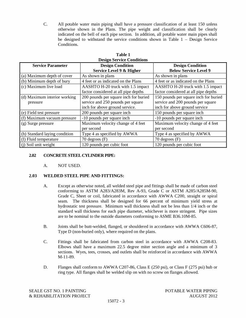
SEALE GST NO. 1 PAINTING POTABLE WATER PIPING& REHABILITATION PROJECT AUGUST 2012
15072 - 3
C. All potable water main piping shall have a pressure classification of at least 150 unlessotherwise shown in the Plans. The pipe weight and classification shall be clearlyindicated on the bell of each pipe section. In addition, all potable water main pipes shallbe designed to withstand the service conditions shown in Table 1 – Design ServiceConditions.
Table 1Design Service Conditions
Service Parameter Design ConditionService Level 9 & Higher
Design ConditionBelow Service Level 9
(a) Maximum depth of cover As shown in plans As shown in plans(b) Minimum depth of bury 4 feet or as indicated on the Plans 4 feet or as indicated on the Plans(c) Maximum live load AASHTO H-20 truck with 1.5 impact
factor considered at all pipe depthsAASHTO H-20 truck with 1.5 impactfactor considered at all pipe depths
(d) Maximum interior working pressure
200 pounds per square inch for buriedservice and 250 pounds per squareinch for above ground service.
150 pounds per square inch for buriedservice and 200 pounds per squareinch for above ground service
(e) Field test pressure 200 pounds per square inch 150 pounds per square inch(f) Maximum vacuum pressure -10 pounds per square inch -10 pounds per square inch(g) Surge pressure Maximum velocity change of 4 feet
per secondMaximum velocity change of 4 feetper second
(h) Standard laying condition Type 4 as specified by AWWA Type 4 as specified by AWWA(I) Fluid temperature 70 degrees (F) 70 degrees (F)(j) Soil unit weight 120 pounds per cubic foot 120 pounds per cubic foot
2.02 CONCRETE STEEL CYLINDER PIPE:
A. NOT USED.
2.03 WELDED STEEL PIPE AND FITTINGS:
A. Except as otherwise noted, all welded steel pipe and fittings shall be made of carbon steelconforming to ASTM A283/A283M, Rev A-93, Grade C or ASTM A285/A285M-90,Grade C, Sheet or coil, fabricated in accordance with AWWA C200, straight or spiralseam. The thickness shall be designed for 66 percent of minimum yield stress athydrostatic test pressure. Minimum wall thickness shall not be less than 1/4 inch or thestandard wall thickness for each pipe diameter, whichever is more stringent. Pipe sizesare to be nominal to the outside diameters conforming to ASME B36.10M-85.
B. Joints shall be butt-welded, flanged, or shouldered in accordance with AWWA C606-87,Type D (non-buried only), where required on the plans.
C. Fittings shall be fabricated from carbon steel in accordance with AWWA C208-83.Elbows shall have a maximum 22.5 degree miter section angle and a minimum of 3sections. Wyes, tees, crosses, and outlets shall be reinforced in accordance with AWWAM-11-89.
D. Flanges shall conform to AWWA C207-86, Class E (250 psi), or Class F (275 psi) hub orring type. All flanges shall be welded slip on with no screw on flanges allowed.

SEALE GST NO. 1 PAINTING POTABLE WATER PIPING& REHABILITATION PROJECT AUGUST 2012
15072 - 4
E. Bolts shall be carbon steel ASTM A307-94, Grade A hex head bolts with ASTM A563-93, Grade A hex head nuts.
F. Gaskets shall be 1/8 inch thick, cloth-inserted rubber corrosive acid and alkali free forpotable water and sewage service conforming to ANSI B16.21-92 and AWWA C207.Flat faced flanges shall require full-face gaskets. Raised faced flanges shall require flatring gaskets.
G. Interior Surfaces. The interior surfaces of all steel pipe, fittings, and specials shall becleaned by sandblasting and then primed and coated in the shop with liquid epoxy 8 milsDFT in accordance with AWWA C210. Cement mortar lining shall NOT be allowed.
H. Exterior steel surfaces for buried pipe and fittings to be protected by coal tar enamel inconformance with AWWA C203.
2.04 DUCTILE-IRON PIPE
A. This specification covers 3” through 64” ductile-iron pipe, centrifugally cast, for water orother liquids, with push-on or mechanical joints. All pipe furnished shall be inconformance with ANSI/AWWA Standard C51/A21.51.91, or latest revision thereof.
1. General Requirements
a. All pipe shall conform to the following pressure classes, based uponType 3 bedding conditions, a depth of bury of 6 feet, and a workingpressure of 150 pounds per square inch:
3” through 12” 350 psi16” and 20” 250 psi24” 200 psi30” through 64” 150 psi
b. Dimensions and tolerances for each nominal pipe size shall be inaccordance with Table 51.5 (push-on) or Table 51.5 (mechanical joint) ofAWWA Standard C151 for pipe with a nominal laying length of 20 feet.
c. All pipes shall have an interior lining applied in accordance withANSI/AWWA C104/A21.4 cement mortar lining.
d. Exterior coating shall consist of a nominal one-mil thick asphalticmaterial applied to the outside of the pipe as described in Section 51.8 ofAWWA C151, plus polyethylene tube encasement.
e. All rubber joint gaskets utilized on ductile-iron pipe shall be inconformance with ANSI/AWWA C111/A21.11 Standard, latest revision.
f. Each length of pipe furnished shall bear identification markings inconformance with Sec. 51.10 of AWWA Standard C151.
g. The manufacturer shall take adequate measures during pipe production toassure compliance with AWWA C151 by performing quality-controltests and maintaining results of those tests as outlined in Sec 51.14 ofthat Standard.
SEALE GST NO. 1 PAINTING POTABLE WATER PIPING& REHABILITATION PROJECT AUGUST 2012
15072 - 5
2.05 POLYVINYL CHLORIDE (PVC) PIPE
A. This specification covers 4 inch through 12 inch diameter Polyvinyl Chloride(PVC) pressure pipe made from class 1245A or 1245B compounds as determinedby ASTM Standard D1784 and providing for a hydrostatic test basis (HDB) of4,000 psi for the conveyance of potable water. All pipe shall be in conformancewith AWWA Standard C900, or latest revision thereof.
1. General Requirements
a. All C900 pipe shall be Class 150 (DR18) having a sustained pressurerequirement of 500 psi (ASTM D2241) and a minimum burst pressure of755 psi (ASTM D1599).
b. Dimensions and tolerances for each nominal pipe sizes shall be inaccordance with Section 2.2, Table 1 of AWWA Standard C900.
c. Pipe shall be furnished in standard laying lengths of 20 feet (plus orminus one inch) unless otherwise noted. Each pipe shall have an integralbell formed on the pipe end, and be designed to be at least as strong asthe pipe wall (ASTM D2472).
d. An elastomeric gasket shall be designed with a retainer ring, which“locks” the gasket into integral bell groove and shall be installed at thepoint of manufacture. Gasket shall be in conformance with ASTM F477.
e. Each length of pipe furnished shall bear identification markings inconformance with Section 2.6 of AWWA Standard C900.
f. The manufacturer shall take adequate measures during pipe production toassure compliance with AWWA C900 by performing quality controltests and maintaining results of those tests as outlined in Section 3 of thatstandard. Submission of product shall constitute certification ofcompliance with that standard.
C. Pipe shall be homogenous throughout. It shall be free from voids, cracks, inclusions, andother defects. It shall be as uniform as commercially practical in color, density, and otherphysical properties. Pipe shall be free from gouges and imperfections that could causeleakage.
D. All PVC pipe shall be bundled in pallets for ease of handling and storage. Pipe bundles(units) shall be packaged to provide structural support to insure that the weight of upperunits shall not cause deformation to pipe in lower units. No pipe bundles shall beaccepted which show evidence of ultraviolet radiation “sunburn” on exposed pipes asmay be caused from extended unprotected storage conditions.
E. The San Antonio Water System may, at no cost to the manufacturer, subject randomlengths of pipe to testing by an independent laboratory for compliance with thisspecification. Any visible defect of failure to meet the quality standards herein will begrounds for rejecting the entire order.
F. The pipe is intended for use as an underground, direct bury pressure pipe for transport ofpotable water. The expected life of the pipe system, after installation, is 25 to 50 years.

SEALE GST NO. 1 PAINTING POTABLE WATER PIPING& REHABILITATION PROJECT AUGUST 2012
15072 - 6
G. A one-year warranty shall be provided for all materials sold and delivered for use andincorporated into the San Antonio water distribution system. Such warranty shall takeeffect on the date that the pipe is received and accepted by an authorized representative ofthe San Antonio Water System.
H. User references and a claims history shall be provided for further investigation, prior torendering a final decision on the acceptance of the product to be furnished.
PART 3 EXECUTION
3.01 GENERAL:
A. Care and Handling of Materials: All materials shall be carefully handled in all steps offabrication, storing, loading, and transporting, unloading, storing at the site, andinstallation, using the means and following the procedures submitted with the approvedshop drawings. Pipe slings used during handling and tie-down straps during transit shallnot be less than 4 inch wide flat fiber or plastic straps. During storage and in transit, pipe(8 inch dia. and larger) shall be rested on saddles or on another support system approvedby the OWNER, which will ensure freedom from damage of the barrel, interior lining,and exterior coating. A minimum of three saddles will be used during transit.
B. Installation: All potable water main pipe shall be installed in accordance with thedrawings and procedures submitted with the approved shop drawings. The interior of thepipe, fittings and couplings shall kept clean and free from contamination duringinstallation. All pipes shall be carefully placed and supported at the proper lines andgrades and where practical shall be sloped to permit complete drainage. Piping runsshown on the plans shall be followed as closely as possible. If relocation is required, theyshall be approved by the OWNER.
C. Verification of Dimensions: All dimensions essential to the correct locations of the pipe,or fit of piping at equipment and valves, or to the proper orientation of pipe sleeves andwall castings, or to the avoidance of obstructions or conflict with other improvements,shall be accurately determined by the CONTRACTOR prior to the fabrication of thepiping involved. All required changes from the nominal location shown on the drawingsshall be made by the CONTRACTOR and shall be included as a part of the work.
D. Installation: All potable water main pipe, fittings, couplings, and appurtenant items shallbe in proper alignment. Assembly and installation shall not result in placing any undoalignment strains or stresses on any flanges or couplings. When connecting flangedjoints care shall be taken in bolting together joints to avoid placing restraint on theopposite end of the piece, which would prevent pressure from being evenly anduniformly applied to the flanged gasket. The pipe or fitting must be free to move in anydirection during the installation of bolts. Bolts shall be gradually tightened in a crisscrosspattern, to ensure a uniform rate of gasket compression around the entire flange.
Special care shall be taken when connecting piping to pumping equipment to ensure thatpiping stresses are not transmitted to the pump flange / pump head. All connecting pipingshall be supported so that accurate matching of bolt holes and uniformed contact over theentire surface of the flanges is obtained before any bolts are installed in the flanges. Inaddition, pump connection piping shall be free to move parallel to its longitudinal centerline while the bolts are being tightened. After final alignment and bolting, the pump

SEALE GST NO. 1 PAINTING POTABLE WATER PIPING& REHABILITATION PROJECT AUGUST 2012
15072 - 7
connections shall be tested for applies piping stresses by loosening the connection thatwas installed by the contractor that is closest to the pump. If the piping is properlyinstalled, no movement of the piping relative to the pump or opening of the connectionjoints shall be noticed. If any movement is observed, then the piping shall be loosenedand re-aligned as needed and then bolted back together. Then the connection shall beloosened again and the process repeated until no movement is observed. Alignmentadjustments will be made below grade to the extent possible.
Mechanical couplings shall be carefully installed in accordance with the manufacturer’srecommendations. A space of at least 1/4 inch, but not more than 3/4 inch, shall be leftbetween the pipe ends. Pipe and coupling surfaces in contact with the gaskets shall beclean and free from dirt and other foreign matter during assembly. All assembly boltsshall be uniformly tightened so the coupling is free from leaks, and all parts of thecoupling are square and symmetrical with the pipe. Wenches used in bolting shall be of atype and size recommended by the coupling manufacturer.
3.02 BURIED PIPING:
A. Installation: Buried piping shall be installed according to the lines and grades shown inthe plans. All trenching, bedding, and backfilling shall conform to the requirementsspecified in Section 02220 - Excavating, Backfilling, and Compaction for Utilities. Otherrequirements include:
1. Open ends of the pipe shall be secured when the work is not in progress.
2. Piping shall be installed when trench and weather conditions are suitable. Nopipe shall be placed in standing water, and the responsibility for divertingdrainage and de-watering all trenches, including meeting all safety requirementsshall be borne by the CONTRACTOR.
3. All pipe in place shall be approved by the Owner as to line, grade, bedding, andproper joint construction prior to backfilling.
B. Joints: Care shall be taken to keep pipe in correct alignment when making joints. Thefitting of piping to valves, wall castings, and other appurtenances shall be worked out inadvance of installation to ensure correct orientation of the mating ends and bedding ofapproach piping. Other requirements include:
1. The maximum deflection in bell and spigot potable water main pipe joints shallnot exceed 75 percent of the manufacturer’s recommendations.
2. The interior mortar lining of CSC pipe at joints shall be smoothly continuous andof full thickness.
3. Bolts and other exterior surfaces of buried joints, rods, and couplings shall begiven a 20 mil coating of KOPR-KOTE High Temp Anti-Seize or approvedequal.
4. When interior joints are protected with mortar, the procedure for mortarplacement shall be as follows. Prior to the placing of mortar, any dirt or trashwhich has collected in the joint shall be cleaned out and the surfaces of the jointspace shall be moistened with water by spraying or brushing with a wet brush.The inside joint recess at the bell end of 36 inch and smaller pipe shall be filledimmediately prior to placing the pipe together by buttering the bell recess withmortar. After the joint is engaged, the joint mortar of pipe 18 inch in diameter

SEALE GST NO. 1 PAINTING POTABLE WATER PIPING& REHABILITATION PROJECT AUGUST 2012
15072 - 8
and smaller shall be smoothed and cleaned with a swab, and the joint mortar ofpipe larger than 18 inch pipe shall be finished off smooth by hand trowel. Theinside joint recess of pipe larger than 36 inch shall be filled with mortar andfinished smooth after the joint is engaged. Careful inspection shall be made ofeach joint to insure a smooth, continuous interior surface.
5. When the exterior joints are protected with mortar, the procedure for mortarplacement shall be as follows:
a. A grout band shall be placed around the pipe and positioned to straddlethe joint recess. The band shall be of sufficient length to essentiallyencircle the pipe and shall be secured in such a manner that joint mortarwill be contained with little or no leakage.
b. For raised-bell (lined cylinder C301) pipe, there shall be no additionalbedding or backfill material placed on either side of the pipe until afterthe mortar band is filled and the mortar has mechanically stiffened. Forall other (flush bell) concrete pressure pipe, bedding and backfill may beplaced and consolidated to approximately three-fourths the height of thepipe before the band is filled to provide support for the band to containthe weight of the mortar.
c. The band shall be completely filled with mortar in one operation byfilling from one side only until the mortar rises on the opposite side, andthen rodded or agitated on both sides of the pipe alternately to settle themortar. The mortar shall then not be agitated for at least 15 minutes toallow excess water to seep through the grout band and to allow themortar to mechanically stiffen. After this period more mortar shall beadded, if necessary, to fill the joint completely.
d. The gap at the top of the joint band shall be protected from penetration ofbackfill into the mortar either by allowing the mortar to stiffen, or bycapping with a stiff mortar mix, or by covering with a structurallyprotective material. The band shall not be removed from the joint.
e. The mortar used at joints shall consist of one part Portland cement to nomore than 3 parts clean sand mixed with water. Interior joint mortarshall be mixed with as little water as possible so the mortar will be verystiff but workable. Exterior joint mortar shall be mixed with water untilit has the consistency of thick cream. During periods of cold weather thejoint mortar shall be adequately protected from freezing.
C. Restraint: All push-on and mechanical joint tees, Y-branches, bends, and plugs which areinstalled in buried piping shall be provided with suitable anchors, joint harness, or otheracceptable means for preventing movement of the pipe caused by internal pressure.Thrust blocking shall not be used alone, a restrained joint pipe system must be usedwhich adequately resists thrust. Shop drawings will include a sealed thrust resistancedesign prepared by a registered professional engineer licensed in the State of Texas.
D. Cover: Unless otherwise shown, all potable water piping shall have a minimum cover of4 feet.

SEALE GST NO. 1 PAINTING POTABLE WATER PIPING& REHABILITATION PROJECT AUGUST 2012
15072 - 9
E. Polyethylene Tube Encasement: All buried steel and ductile iron pipe shall be encased inpolyethylene tubing. Installation procedures for polyethylene tube encasement are asfollows:
1. Installation of polyethylene tube encasement for pipe and fittings shall be inaccordance with Method A of ANSI A21.5 and as specified herein.
2. Each pipe joint shall be covered with a 4.0 mil thick polyethylene sleeve that is 4feet longer than the pipe joint. The sleeve shall cover the entire length of thepipe joint, lap over 2 feet on each end of the adjoining pipe joints and be securedwith a minimum of 2 circumferential turns of pressure sensitive tape every 5feet.
3. Excess material should be neatly drawn up and around the pipe barrel, folded intoan overlap on top of the pipe and held in place by means of pressure sensitivetape.
4. After assembling the joint, the polyethylene tube from the previously installedpipe shall be pulled over the joint and secured to the pipe barrel. Thepolyethylene tube from the new joint is then pulled over the first joint andsecured with polyvinyl pressure sensitive tape that conforms to AWWA C209and Federal Specification L-T-1512A, to create a double seal.
5. Fittings shall also be wrapped in 4 mil polyethylene film with a minimum of 1foot overlap on each end.
6. Any damaged areas in the polyethylene film shall be repaired by covering thearea with a sheet of polyethylene film large enough to lap over the damaged area1 foot in any direction. This patch shall be securely taped to the originalpolyethylene tube. All edges of the patch are to be taped with polyvinyl pressuresensitive tape. Backfill shall be carefully placed to avoid damage to thepolyethylene tubing.
3.03 ABOVE GROUND PIPING:
A. Installation: All piping shall be installed in accordance with the erection drawings and theerection procedure submitted with the approved shop drawings. Horizontal piping shallbe run parallel to building walls and shall be level, except where otherwise shown.Parallel lines shall be grouped on the same horizontal or vertical plane wherever possible.Vertical piping shall be plumb and the entire piping configuration shall provide adequateclearances for painting and maintenance. Piping shall clear obstructions, preserveheadroom, and keep openings and passageways clear. If structural difficulties or otherwork prevent the running of pipes or the setting of equipment at the point indicated on thedrawings, the necessary minor deviations therefrom, as determined by theCONTRACTOR and approved by the Owner, will be allowed. All changes will beshown on the record drawings.
B. Joint Installation: Installation of joints and couplings shall conform to the following:
1. Joints and couplings shall be made in accordance with the specified requirementsmade part of the erection procedure submitted by the CONTRACTOR andapproved by the OWNER. The minimum distance between the harness clips forflexible couplings shall be a minimum of 2 times the dresser length plus 12”.

SEALE GST NO. 1 PAINTING POTABLE WATER PIPING& REHABILITATION PROJECT AUGUST 2012
15072 - 10
2. Pipe threads shall be made in accordance with the requirements of ANSI B2.1,and shall be cut full and free from torn or ragged surfaces. No more than 3threads on the pipe at any joint shall remain exposed after installation. Threadedjoints shall be established with Teflon tape or joint compound applied to the maleends only. The use of thread cement or caulking will not be permitted.
3. Flanged joints shall be made with gaskets centered in the joint. Bolts, studs, andnuts shall be lubricated with graphite or oil so that the nuts can be turned byhand. Care shall be taken to prevent excessive initial tension to the bolt and studsso that the tension applied is as nearly uniform as possible. The rust preventativecompound applied to the faces before shipment shall be removed beforeinstallation.
5. Mechanical coupling type joints of the sleeve, grooved mechanical, split sleeve,and flanged coupling adapter types shall be made in accordance with themanufacturer’s printed instructions.
C. Pipe Sleeves: All piping which will pass through walls and slabs shall be provided withpipe sleeves with the annular space sealed or with wall castings. The CONTRACTORshall provide the wall sleeves and castings for insertion into the concrete work and shallverify their correct setting prior to concrete placement. Sealing of the wall sleeves shallbe made with mechanical link seals, appropriately sized for the through-pipe. Installationof the link seal shall made in accordance with recommendations of the manufacturer.
D. All above ground piping and valves shall be exterior coated as detailed in Section 09885– Exterior Coating System for Yard Pump, Piping, and Electrical Equipment Enclosures.
END OF SECTION

SEALE GST NO. 1 PAINTING DISINFECTION OF WATERLINES& REHABILITATION PROJECT AUGUST 2012
15073-1
SECTION 15073
DISINFECTION OF WATERLINES
PART 1 GENERAL
1.01 SCOPE OF WORK
A. This Specification covers the disinfection of potable waterlines.
B. The CONTRACTOR shall provide all necessary equipment, materials, labor, andassistance required to disinfect, test, and analyze plant and station piping systems asspecified herein.
C. Have independent commercial laboratory approved by SAWS collect and analyzesamples at no extra cost to SAWS.
1.02 RELATED WORK:
A. Section 01300 – Submittals.
B. Section 01025 – Measurement and Payment.
C. Section 01400 – Quality Control.
D. Section 15072 – Potable Water Piping
1.03 MEASUREMENT AND PAYMENT:
A. No separate payment will be made for disinfection of waterlines under this Section.Include cost in unit price of waterlines being disinfected.
B. Refer to Section 01025 – Measurement and Payment for measurement and paymentprocedures.
1.04 REFERENCED STANDARDS (Latest Revisions)
A. AWWA C651 – Disinfecting Water Mains.
B. SAWS Standard Specification for Construction, Item No. 847 except as modified herein.
1.05 QUALITY ASSURANCE:
A. All work shall comply with Section 01400 – Quality Control.
1.06 SUBMITTALS
A. Submit a description of chlorine dosages and methods of application to SAWS Engineerfor review and approval prior to disinfection of any piping system.

SEALE GST NO. 1 PAINTING DISINFECTION OF WATERLINES& REHABILITATION PROJECT AUGUST 2012
15073-2
B. Submit laboratory reports on bacteriological analyses to SAWS Engineer within ten (10)working days after taking samples.
C. Refer to Section 01300 – Submittals.
1.07 GENERAL SEQUENCE OF WORK
A. Perform disinfection of designated piping systems after construction, cleaning, andtesting of same.
B. Following disinfection and flushing, collect samples of water from piping system forbacteriological analysis.
C. Have samples analyzed by an approved independent commercial laboratory and submitlaboratory report to SAWS Engineer for approval.
D. Do not place piping systems in service until after receipt of SAWS Engineer’s approvalof bacteriological reports.
PART 2 PRODUCTS – NOT USED
PART 3 EXECUTION
3.01 GENERAL:
A. All waterlines constructed shall be promptly disinfected before any tests are conducted onwaterlines and before waterlines are connected to SAWS’ water distribution system.
B. Water for disinfection and flushing will be furnished by SAWS without charge.
C. Unless otherwise provided on Contract Documents, SAWS will conduct disinfectionoperations assisted by CONTRACTOR.
3.02 PREPARATION:
A. Furnish required temporary blind flanges, cast-iron sleeves, plugs, and other items neededto facilitate disinfection of new mains prior to connecting them to SAWS’ waterdistribution system. Normally, each valved section of waterline requires two each, 1-inchtaps. A 4-inch minimum blow-off is required for CSC waterlines 20-inch and larger.
B. Fire hydrants shall be used as blow-offs to flush newly constructed waterlines 8-inchdiameter and above. Where fire hydrants are not available on waterlines, locations anddesigns for blow-offs shall be as indicated on Drawings. Install temporary blow-offvalves and remove promptly upon successful completion of disinfection and testing.
C. Slowly fill each section of pipe with water in a manner approved by SAWS Engineer.Average water velocity when filling pipeline should be less than 1 fps and shall not,under any circumstance, exceed 2 fps. Before beginning disinfection operations, expelair from pipeline.
D. Excavations shall be backfilled immediately after installation of risers or blow-offs.

SEALE GST NO. 1 PAINTING DISINFECTION OF WATERLINES& REHABILITATION PROJECT AUGUST 2012
15073-3
E. Install blow-off valves at end of main to facilitate flushing of dead-end water mains.Install permanent blow-off valves as per SAWS Standard Drawing DD-844-05.
3.03 DISINFECTION OF NEW MAINS UTILIZING MACHINE CHLORINATION:
A. General: After the new mains have successfully passed the pressure test specified inSpecification 15074, Section 3.04 - Testing, the Owner will disinfect those mains shownon the plans or otherwise indicated as “Machine Chlorination by San Antonio WaterSystem”. This disinfection shall include chlorination, flushing, and placing the mains inservice.
B. Operation of Valves: During and after the disinfection of the mains, the CONTRACTORshall be notified by the Engineer sufficiently in advance to enable the CONTRACTOR tohave a competent representative present whenever valves are to be operated that willaffect the pressure in any part of the work for which the CONTRACTOR is responsible.
C. CONTRACTOR’s Personnel and Equipment: The CONTRACTOR shall supply laborand equipment necessary to make all excavations required for chlorination, equipmentconnections, subsequent flushing, and placing the mains in service.
B. Safeguarding and Backfilling Open Holes: The CONTRACTOR shall be responsible forsafeguarding any open holes excavated or left open for flushing and disinfectionpurposes. Following completion of disinfection, the CONTRACTOR shall backfill suchholes in accordance with appropriate provisions of Specification 02220 – Excavating,Backfilling & Compaction for Utilities of these Contract Documents.
3.04 DISINFECTION BY SAWS PERSONNEL:
A. Correct problems that may prevent disinfection operations prior to advising SAWSEngineer to perform disinfection work. When disinfection work cannot be performeddue to covered up valves, missing valve stacks, inoperative fire hydrants or other nonconforming construction, a base charge of $135.00 will be levied againstCONTRACTOR for each trip made by SAWS personnel.
B. Notify and coordinate with SAWS Engineer and Service Center personnel a minimum of48 hours before disinfection work is to be performed. Assist SAWS personnel duringdisinfection operations.
3.05 DISINFECTION BY CONTRACTOR:
A. The following procedure will be used when disinfection by CONTRACTOR is requiredby Contract Documents:
1. Use not less than 100 parts of chlorine per million parts of water.
2. Introduce chlorinating material to water lines in accordance with AWWA C651.
3. After contact period of not less than 24 hours, flush system with clean water untilresidual chlorine is no greater than 1.0 part per million parts of water.

SEALE GST NO. 1 PAINTING DISINFECTION OF WATERLINES& REHABILITATION PROJECT AUGUST 2012
15073-4
B. If a chemical compound is used for a sterilizing agent, it shall be placed in pipes asdirected by SAWS Engineer.
3.06 BACTERIOLOGICAL TESTING:
A. After disinfection and flushing of waterlines, bacteriological tests will be performed bySAWS or testing laboratory in accordance with Specification 01400, Section 1.07TESTING LABORATORY SERVICES. If test results indicate need for additionaldisinfection of waterlines based upon Texas Department of Health requirements,CONTRACTOR shall assist SAWS with additional disinfection operations.
B. Subsequent disinfection operations which may be necessary due to non-conforming orincomplete construction will be charged to CONTRACTOR. Total charge will consist ofbase charge of $135.00 plus footage charge based on number of feet of specified diameterpipe in construction project. Footage charge is as follows:
Size of Pipe Charge ($) per Linear Foot2-inch to 4-inch 0.036-inch 0.048-inch 0.0510-inch to 12-inch 0.0716-inch to 20-inch 0.0924-inch to 30-inch 0.13
Charges will be deducted from retainage amounts when construction estimates areprocessed for final payment.
3.07 COMPLETION:
A. Upon completion of disinfection and testing, remove risers except those approved for usein subsequent hydrostatic testing, and backfill excavation promptly.
END OF SECTION

SEALE GST NO. 1 PAINTING WATER PIPELINE TESTING& REHABILITATION PROJECT AUGUST 2012
15074-1
SECTION 15074
WATER PIPELINE TESTING
PART 1 GENERAL
1.01 SCOPE OF WORK
A. This Section covers field pipeline cleaning and hydrostatic pressure and leakage testingof all piping installed under this Contract. The term "piping" shall be used in this Sectionto refer to piping systems, pipelines, or sections thereof.
1.02 GENERAL REQUIREMENTS
A. The CONTRACTOR shall furnish all labor, materials, equipment, and incidentals toperform flushing, cleaning, and nondestructive sonic, pressure, and/or leakage testing ofall pipeline segments and appurtenant piping in accordance with the Contract Documents.
B. The CONTRACTOR shall be responsible for coordinating testing and providing adequateand safe access to all pipeline segments.
C. The Owner shall be present during testing and shall be notified of the time and place oftesting at least three (3) days prior to commencement of testing. All testing shall beperformed to the satisfaction of Owner and in accordance with all governing standardsand regulations.
D. The CONTRACTOR shall be responsible for furnishing the water for filling, de-pressurizing and testing the piping, including makeup water. Potential sources of waterare identified in this Section.
E. Unless otherwise permitted, during testing, the water shall be kept out of the remainder ofthe piping not being tested.
F. As a conservation measure, the water may be collected for reuse in subsequent testing.
G. CONTRACTOR shall notify federal, state, and local regulatory agencies to determine ifany special procedures or permits are required for disposal of water used for pipelinetesting and cleaning and to identify acceptable locations for disposal of the water. Allrequirements and costs associated with notifications and obtaining any discharge permitor approvals shall be responsibility of CONTRACTOR. In addition to complying withany federal, state, or local requirements regarding water disposal, following completionof testing, CONTRACTOR shall dispose of water in a manner acceptable to Owner.
H. For air and other testing of gasketed and other joints as applicable, refer to the associatedpipe specification.

SEALE GST NO. 1 PAINTING WATER PIPELINE TESTING& REHABILITATION PROJECT AUGUST 2012
15074-2
1.03 RELATED WORK
A. Section 01330 - Submittals
B. Section 15072 - Potable Water Piping
1.04 SUBMITTALS
A. A testing schedule, including proposed plans for water source and conveyance, control,and disposal shall be submitted in accordance with Section 01330 - Submittals in writingfor acceptance a minimum of 10 work days before each test is to start. The schedule shallindicate the proposed time and sequence of testing of the piping.
B. Written pressure and leakage test procedures, required pipeline appurtenances, andtesting personnel qualifications. The test procedures shall establish the limits of thepiping to be tested, the positions of all valves during testing, the locations of temporarybulkheads, and all procedures to be followed in performing the testing.
C. Certified test reports documenting the results of the hydrostatic pressure and leakagetests.
D. Gauges and water meter calibration reports.
PART 2 PRODUCTS
2.01 GENERAL
A. Makeup water is defined as the quantity of water required to be pumped into the pipe tobe tested, or any valved section of it, necessary to maintain the specified test pressureafter the pipe has been filled with water and the air expelled.
2.02 TEST EQUIPMENT
A. All necessary connections between the piping to be tested and the water source, togetherwith pumping equipment, water meter, pressure gauges, backflow prevention and allother equipment, materials, and facilities required to perform the specified tests, shall befurnished by the CONTRACTOR. All required blind flanges, valves, bulkheads, bracing,and other sectionalizing devices shall also be provided. The CONTRACTOR shall usetemporary bulkheads, which shall be removed upon completion of testing. The removalof the temporary bulkheads shall be performed in a manner to minimize damage to thecement mortar lining and tape coating systems. The CONTRACTOR may use an airgauge and a skip method of cutting to remove the temporary bulkheads or any otherbulkhead removal method as recommended by the pipe manufacturer. Vents shall beprovided in test bulkheads where necessary to expel air from the piping to be tested. Nomaterials shall be used which would be injurious to the construction or its future function.
B. Test pressures shall be applied by means of a force pump sized to produce and maintainthe required pressure without interruption during the test.

SEALE GST NO. 1 PAINTING WATER PIPELINE TESTING& REHABILITATION PROJECT AUGUST 2012
15074-3
C. The water necessary to maintain the test pressure shall be measured through a watermeter satisfactory to the Owner.
D. Water meters and pressure gauges shall be accurately calibrated and shall be subject toreview and acceptance by the Owner.
E. Pressure gauges shall be ANSI/ASME B40.1, Grade 1A and shall meet or exceed the testpressures specified in this Section. Pressure gauges shall be calibrated to an accuracy ofplus or minus 1 percent minimum over the entire range of the gauge. The gauges shall belaboratory bench tested for accuracy just prior to field testing.
F. Permanent gauge connections shall be installed at each location where test gauges areconnected to the piping during the required tests. Field drilling and tapping of pipe wallswill not be permitted. Upon completion of testing, each gauge connection shall be fittedwith a removable plug or cap acceptable to the Owner.
G. Permanent or temporary fill and vent connections shall be installed as needed for therequired test. Drilling and tapping of pipe walls will not be permitted. Upon successfulcompletion of testing, each permanent fill and vent connection shall be fitted with thepermanent fill or vent piping, and each temporary fill and vent connection, if used, shallbe fitted with a permanent sealed plug or cap acceptable to the Owner.
2.03 WATER FOR TESTING
Potential water source alternatives for CONTRACTOR’s use for pipeline filling, testing, andcleaning are as follows:
A. Seale Pump Station:
1. Water for testing at the Seale Pump Station facility will be provided by the Owner.Contractor will be responsible for coordinating with SAWS Inspector for use ofOwner provided water.
PART 3 EXECUTION
3.01 GENERAL
A. The CONTRACTOR may test the pipeline in sections when all the pipe in a particularsection has been completely backfilled and in place for at least 14 days. Associatedrestrained joint piping shall also be complete prior to testing.
B. Unless otherwise acceptable or indicated in the Contract Documents, during testing of thepipeline, all valves shall be in the open position and temporary bulkheads shall beprovided so that the test pressures are not applied to existing or new closed valves andhydrants, or to existing water lines, or to any portion of water lines installed under thisContract that have already been put into service.
C. Prior to testing, place temporary bulkheads in the pipe and fill the line slowly with water.Care shall be taken to ensure that all air release valves and vents are properly installedand in the open position during the filling. Hand operated vent valves shall not be closed

SEALE GST NO. 1 PAINTING WATER PIPELINE TESTING& REHABILITATION PROJECT AUGUST 2012
15074-4
until an uninterrupted stream of water is flowing from each valve. The pipeline shall befilled at a rate which will not cause any surges or exceed the rate at which the air can bereleased through the air valves. Filling shall be at a reasonable velocity and all the airwithin the pipeline shall be properly purged. In no case shall the filling rate result in aflow velocity of more than 0.5 foot per second as measured using the full cross-sectionalarea of the pipe.
D. After the line or section thereof had been completely filled, it shall be allowed to standunder a slight pressure for at least 24 hours to allow the lining to absorb what water it willand to allow the escape of air from any air pockets. During this period, the bulkheads,valves, manholes, and connections shall be examined for leaks. If any are found, theseshall be repaired.
E. Piping shall be adequately anchored and supported before the test pressure is applied.
F. During filling and testing, the CONTRACTOR shall monitor the pipeline alignment forsigns of leaks. If leaks are found, the testing shall be halted until the leaks are repaired.Water damage due to testing operations shall be corrected at the CONTRACTOR’sexpense including leakage, runoff and erosion to areas outside of the pipeline easement orleakage that may cause damage to installed facilities. The CONTRACTOR shallmaintain equipment on site, including earthmoving equipment, to mitigate and repair anydamage from leaks.
G. CONTRACTOR shall furnish all necessary equipment and make tests at no additionalcost to the Owner.
3.02 PIPELINE CLEANING
A. The CONTRACTOR is required to keep the pipe interior free of all debris. TheCONTRACTOR shall completely clean the interior of the pipe of all sand, dirt, mortarsplatter and any other debris following completion of pipe laying, grouting of joints andany necessary interior repairs prior to testing the completed pipeline. TheCONTRACTOR shall clean by broom sweeping or other means that will not destroy ordamage the inside lining and joint protection system as recommended by the pipemanufacturer and accepted by the Owner.
3.03 HYDROSTATIC PRESSURE AND LEAKAGE TESTS
A. Test Section Length. Pressure and leakage tests will be required to be performed by theCONTRACTOR at the completion of each segment of the pipeline work.
B. Hydrostatic Pressure Test Procedure. The hydrostatic pressure test shall consist ofapplying and maintaining the test pressure on the pipeline, without interruption andwithin a range of plus or minus 5 psi of the test pressure, for a period of 2 hours plus anyadditional time required for the Owner to examine all piping being tested and forCONTRACTOR to locate any defective joints and pipe materials. The test pressuregradients for each segment shall be 100 percent of the design test pressure as shown onthe Drawings. The design test pressure shall be the greater of the hydraulic pressure orthe mitigated transient pressure associated with the ultimate flow rate. The maximum testpressure shall be measured at the lowest point of the pipeline section being tested.
SEALE GST NO. 1 PAINTING WATER PIPELINE TESTING& REHABILITATION PROJECT AUGUST 2012
15074-5
During the test, the entire pipeline section being tested shall be inspected to locate anyleaks or breaks. Any defective joints, cracked or defective pipe, fittings, valves, or weldsdiscovered during this hydrostatic pressure test or visual inspection shall be removed andreplaced with sound material and the test shall be repeated until satisfactory results areobtained at no additional cost to the Owner.
D. Valve Pressure Test. Pressure test valves, as installed in the field, and adjust valves asnecessary for drip-tight performance. Valves shall be tested with pressure equal to thepressure class of the valve or pipeline hydrostatic test pressure, whichever is less. Testpressure shall be applied to each side independently, and the valve tested for drip-tightperformance with zero pressure on the other side of the valve. Provisions satisfactory tothe Owner shall be made for verifying “0" leakage within the duration of the test. Testduration shall be 2 hours plus any additional time required by the Owner for examination.If pressure class of valve is less than the pipeline hydrostatic test pressure at the valvelocation, the valve shall then be opened for the pipeline hydrostatic test.
E. Leakage Test Procedure. Following completion of hydrostatic pressure testing andacceptance by Owner, the piping shall be subjected to a leakage test.
1. The duration of the leakage test shall be 2 hours plus the additional time requiredfor the Owner to make an accurate determination of leakage.
2. The hydrostatic pressure maintained during the leakage test shall be at least 75percent, but not more than 100 percent, of the pressure specified for pressuretesting of the piping and shall be maintained within plus or minus 5 psi duringthe entire time that leakage measurements are being performed.
3. Measurement of leakage shall not be attempted until all trapped air has beenvented and a constant test pressure has been established. After the pressure hasstabilized, piping leakage shall be measured with a suitable water meter installedin the pressure piping on the discharge side of the force pump.
4. The term "leakage", as used herein, refers to the total amount of makeup waterwhich must be added into the piping during the leakage test to maintain the testpressure.
No piping will be accepted if and while it exhibits a leakage rate in excess of thatdetermined by the indicated formula:
Q = [0.00135]DLN (using inch-pound units)
Where
Q = allowable leakage in gallons per hour
D = nominal diameter of pipe in inches
L = length of section tested in thousand feet
N = square root of weighted average test pressure in pounds per
square inch

SEALE GST NO. 1 PAINTING WATER PIPELINE TESTING& REHABILITATION PROJECT AUGUST 2012
15074-6
The weighted average test pressure shall be equivalent to the arithmeticdifference between the specified test pressure plane elevation in feet and theaverage elevation of the pipeline in feet, multiplied by 0.433 to obtain psi. Theweighted average elevation of the pipeline shall be calculated by (1) breaking thepipeline into sections at each significant change in slope and multiplying theaverage elevation of each section by the length of each section, (2) then summingthe products, and (3) dividing the sum by the total length of the pipeline.
Example: What is the maximum allowable leakage for the 1 mile (5,280 LF) of54” diameter pipe with gasketed joints tested 2 hours at a weighted average testpressure of 270 psi:
Answer: Q = 0.00676 DLNQ = 0.00676 (54 in) (5.28 thousand LF) (270 psi)0.5
Q = 31.67 gallons per hour,
For 2 hours the total maximum allowable leakage is then 2 hrs x31.67 gal/hr = 63.34 gallons.
The allowable leakage shall be calculated based on the actual length of pipeline beingtested. Whenever the piping to be tested contains pipe of different diameters, theallowable leakage shall be calculated separately for each diameter and the correspondinglength of piping. The resulting allowable leakage rates shall be added to obtain the totalallowable leakage for the pipeline section being tested.
F. All pipelines and directly connected appurtenant piping shall have no visually detectableleakage and shall not exceed the maximum allowable leakage during the test period. Ifleakage is detected by testing or by visual inspection, determine the cause of the leakage,take corrective measures necessary to repair the leaks, and again test the pipelines untilsatisfactory results are obtained at no additional cost to the Owner. A successful“passed” test shall be defined as a test where the amount of water required to be pumpedinto the piping to maintain the leakage test pressure for the specified duration is less thanor equal to the specified allowable leakage.
G. All joints in piping shall be free from visible leaks during the leakage test. Each leakwhich is discovered within the correction period stipulated in the General Conditionsshall be repaired by and at the expense of CONTRACTOR regardless of the amount thatthe total leakage may have been below the specified allowable leakage rate during theleakage test.
H. Pipelines that fail to pass the specified leakage test will be considered defective Work,and the CONTRACTOR shall determine the cause of the leakage, shall take correctivemeasures necessary to repair the leaks, and shall retest the pipeline.
3.05 DISPOSAL OF WATER
A. After the final section in each pipeline segment has been successfully tested, theCONTRACTOR shall discharge the test water in a manner that will not cause erosion toadjacent ground or damage to installed facilities. The velocity of pipeline drainage for thecarrier pipe shall not exceed 0.5 ft/s. Draining shall be controlled by locating an orifice

SEALE GST NO. 1 PAINTING WATER PIPELINE TESTING& REHABILITATION PROJECT AUGUST 2012
15074-7
plate to be designed by the CONTRACTOR in the 12-inch section of the drain pipe priorto discharge.
B. At the CONTRACTOR’s option, the hydrostatic test water may be disposed of by thefollowing methods:
1. Discharging to local drainage ditch, creek, stream, river, or other surface waterbody.
C. If CONTRACTOR selects the first option, he/she must comply with general permitnumber TXG670000 from the Texas Commission on Environmental Quality (TCEQ) fordischarges of hydrostatic test water into or adjacent to waters of the state.CONTRACTOR shall submit a notice of intent to the TCEQ unless the followingexemptions to the permit for new facilities (TAC 30 Part 1 Chapter 321 Subchapter GRule 321.103) are met:
1. The discharge meets the following effluent criteria:
Maximum Discharge Effluent Concentrations
Constituent Daily Maximum Limit (mg/l)Chemical Oxygen Demand 250.00Total Organic Carbon 85.00Oil & Grease 15.00Chlorine 0.10
2. Water used for the hydrostatic test does not contain corrosion inhibitors, anti-freeze compounds, or other chemical additives.
3. The discharge is controlled at a rate to prevent flooding and/or erosion of thedischarge area.
4. The discharge does not cause any nuisance conditions to adjacent land ownersalong the discharge route.
The TCEQ requires that one grab sample be taken during the first hour and last hour ofdischarge to analyze water quality. Owner will be responsible for collecting and testingthe grab samples in accordance with Standards Methods for the Examination of Waterand Wastewater. CONTRACTOR shall notify Owner at least three (3) days prior to thestart of discharge of water.
D. CONTRACTOR shall be responsible for complying with any other Federal, State, orlocal requirements regarding water disposal, including notifications and any dischargepermit or approvals that may be required.
END OF SECTION

This page intentionally left blank.

SEALE GST NO. 1 PAINTING PIPE CORROSION CONTROL& REHABILITATION PROJECT AUGUST 2012
15099-1
SECTION 15099
PIPE CORROSION CONTROL
PART 1 GENERAL
1.01 RELATED DOCUMENTS:
A. Drawings and general provisions of the Contract, including General and SupplementaryConditions and Division 1 Specification Sections, apply to this Section.
1.02 DESCRIPTION:
A. This Section will govern the installation of pipe coverings, wrappings, dielectric unions,flanges, couplings, and nipples to protect piping corrosion.
1.03 SCOPE OF WORK:
A. The work of this section will include the furnishing, installing, and testing of pipecoverings, wrappings, dielectric unions, flanges, couplings and nipples as shown on thedrawings and as specified herein.
1.04 RELATED WORK:
A. Section 01300 - Submittals
B. Section 01640 - Manufacturer’s Field Services
C. Section 02220 - Excavating, Backfilling, and Compaction for Utilities
D. Section 15100 - Valves and Actuators
1.05 CONTRACTOR SUBMITTALS:
The following submittals shall be provided to the Owner for review and approval prior tobeginning work. All submittals will be in accordance with the provisions of Section 1300 -Submittals.
A. Protective coating schedules that show shop and field surface preparations, materials,methods of applications, dry thickness, and tests for coating defects.
B. Manufacturer’s literature, describing all materials, recommendations for installation andtesting.
C. Dielectric fittings, unions, flanges, couplings, and nipples.
1.06 REFERENCES:
A. American Water Works Association (AWWA)
1. AWWA C203 – Coal Tar Protective Coatings for Steel Water Pipelines Enameland Tape – Hot Applied.

SEALE GST NO. 1 PAINTING PIPE CORROSION CONTROL& REHABILITATION PROJECT AUGUST 2012
15099-2
2. AWWA C209 – Cold Applied Tape Coatings for the Exterior of SpecialSections, Connections and Fittings for Steel Water Pipelines.
B. American National Standards Institute (ANSI)
1. ANSI B31.1-94 – Power Piping
PART 2 PRODUCTS
2.01 GENERAL:
A. Dielectric Fittings. Assembly or fitting with insulating material isolating joineddissimilar metals to prevent galvanic action and corrosion.
1. Description: Combination of copper alloy and ferrous; threaded, solder, plain,and weld-neck end types and matching piping system materials.
2. Dielectric Unions: Factory-fabricated union assembly, designed for 250-psig(1725-kPa) minimum working pressure at 180° F (82° C). Include insulatingmaterial isolating dissimilar metals and ends with inside threads according toASME B1.20.1.
3. Dielectric Flanges: Factory-fabricated companion flange assembly, for 250- or300-psig (1725- or 2070- kPa) minimum pressure to suit system pressures.
4. Dielectric-Flange Insulation Kits. Field assembled companion-flange assembly,full-face or ring type. Components include neoprene or phenolic gasket,phenolic or polyethylene bolt sleeves, phenolic washers, and steel backingwashers.
5. Provide separate companion flanges and steel bolts and nuts for 250- or 300- psig(1725- or 2070- kPa) minimum working pressure to suit system pressures.
6. Dielectric Couplings. Galvanized-steel couplings with inert and noncorrosivethermoplastic linings, with combination of plain, threaded, or grooved end typesand 300-psig (2070- kPa) minimum working pressure at 225° F (107° C).
7. Dielectric Nipples: Electroplated steel nipples with inert and noncorrosivethermoplastic linings, with combination of plain, threaded, or grooved end typesand 300-psig (2070- kPa) minimum working pressure at 225° F (107° C).
B. Wrapping Coatings:
1. Cold applied tapes to bare metal or primer.
2. Machine applied tape to hot primer.
3. Heat shrink wrap.

SEALE GST NO. 1 PAINTING PIPE CORROSION CONTROL& REHABILITATION PROJECT AUGUST 2012
15099-3
PART 3 EXECUTION
3.01 GENERAL:
A. Care and Handling of Materials: All materials shall be carefully handled in all steps offabrication, storing, loading, and transporting, unloading, storing at the site, andinstallation, using the means and following the procedures submitted with the approvedshop drawings. Repair damaged pipe coatings by cleaning to the bare metal andreplacing coating equal to original condition.
B. Corrosion Protection for Ferrous Pipe, Fittings, and Valves: Except as otherwise shownon the plans or as directed by the Engineer, anti-corrosion embedment shall be providedfor all ductile-iron pipe, fittings, and valves and at all valves, fittings, or outlets fornonferrous or reinforced concrete steel cylinder pipe. The embedding material shall besilica sand that conforms to the requirements for “Sand” as set forth in the MaterialSpecifications. The preparation of the trench shall be in accordance with the applicableprovisions of Section 02220 – Excavation, Backfilling and Compaction for Utilities. Thepipe, fitting, or valve shall be firmly embedded in and surrounded by an insulatingblanket of the embedding material. The minimum thickness of this blanket shall be 6inches in every direction. Compaction of the embedding material shall be in accordancewith Section 02220 – Excavation, Backfilling and Compaction for Utilities.
1. Coating and Wrapping of Underground Pipe In a Bore:
a. Ductile-Iron Pipe: Where ductile-iron pipe is to be installed in a bore,the pipe shall be thoroughly cleaned down to the coal-tar enamel pipecoating by approved methods. A prime coat compatible to the polyvinyltape to be used shall then be applied to the pipe. Following theapplication of the prime coat the pipe shall be wrapped with Scotchrap,Trantex V-10 polyvinyl tape, or approved. The tape shall not be applieduntil the prime coat is completely dry. Cold applied tape shall complywith AWWA Standard C209-95. Hot applied coal-tar coatings shallcomply with AWWA Standard C203-91. The tape shall be spirally andtightly wrapped on each section of the pipe with a 50 percent lap. Thewrap shall be made to the bell, on the bell end and to a point 6 inchesfrom the spigot end. The joint shall be protected with tape 6 inches inwidth on pipe 12 inches or less in size and with tape 8 inches in width onpipe greater than 12 inches in size.
b. Steel Pipe: The procedure for coating and wrapping steel pipe shall bethe same in general as that for ductile-iron described herein, except thatthe surface of the pipe shall be cleaned down to bare metal by wirebrushing with a power driven wire brush, sand blasting, or otherapproved methods. Each section of pipe shall be cleaned, primed, andwrapped to within 6 inches of each end, and after the weld has beenmade the remaining portion shall be cleaned to the end down to baremetal. The priming and wrapping shall be completed, and the bare pipewrapped with tape lapped 3 inches over the originally taped sections.Burns from “weld spatter” on previously taped areas shall be carefullypatched using the same methods as for the original application. Theprocedure for coating flanged joints and mechanical coupling jointswhen used with steel pipe shall be as specified in Paragraph 2 “ProtectiveCoatings on Joints” of this Section.

SEALE GST NO. 1 PAINTING PIPE CORROSION CONTROL& REHABILITATION PROJECT AUGUST 2012
15099-4
2. Protective Coating on Joints: All bolts and nuts destined for underground serviceon valves, cast-iron mechanical joint fittings, pipe joints, and other ferrous metalappurtenances shall be packed in an approved asphaltic material after installation.After the joint has been made and bolts drawn to the proper tension, the jointincluding glands, flanges, bolt heads, and nuts shall be packed in asphalticmaterial such as Talcote, GS-722, or approved equal, to a minimum thickness of1-inch over all surfaces.
3. Heat Shrinkable Pipe Coatings: Heat shrinkable pipe coatings shall comply withAWWA C216-94, Heat Shrinkable Cross Linked Polyolefin Coatings for theExterior of Special Sections Connections and Fittings for Steel Water Pipelines.Installation shall be in accordance with manufacturer’s recommendations.
END OF SECTION

SEALE GST NO. 1 PAINTING VALVES AND ACTUATORS& REHABILITATION PROJECT AUGUST 2012
15100-1
SECTION 15100
VALVES AND ACTUATORS
PART 1 GENERAL
1.01 DESCRIPTION:
A. The CONTRACTOR shall furnish all tools, equipment, materials, and supplies and shallperform all labor required to furnish and install all valves, actuators and appurtenancesshown on the plans and specified herein.
1.02 SCOPE OF WORK:
A. The work of this section shall include the furnishing, installation, and testing of allvalves, actuators and appurtenances as specified herein, shown on the plans, and asrequired to make the facility operable and complete. Items to be provided include, butshall not be limited to the following:
1. Valves
2. Actuators, operators, and valve boxes.
1.03 RELATED WORK:
A. Related work not included in this section can be found in the following sections:
1. Section 02220 - Excavation, Backfilling and Compaction for Utilities.
2. Division 15 - Mechanical
1.04 SUBMITTALS:
Provide the following in conformance with applicable requirements contained in Section 01300 -Submittals.
A. Shop Drawings: Submit shop drawings for valves, actuators and miscellaneouscomponents. Shop drawings shall be complete with bill-of-materials showing kind andclass of materials and catalog and engineering data showing compliance with thespecified requirements.
B. Certified shop drawings shall include the principal dimensions, general constructionand material specification of the valve proposed. The number of turns to open (close)shall be clearly noted in the valve information submitted with the proposaldocuments. The number of turns to open or close the valve shall be consistent foreach valve size for each approved manufacturer.
C. For each type and model of valve and actuators provide the following:
1. Assembly instructions and spare parts list.
2. Preventative/corrective maintenance instructions.
3. Certificate of seat exposure with entailed fluid exposure.

SEALE GST NO. 1 PAINTING VALVES AND ACTUATORS& REHABILITATION PROJECT AUGUST 2012
15100-2
D. Erection Drawings: Erection drawings shall include the procedures to be used in setting,supporting, and anchoring the valves, the fitting of the line pipe to the valves for propercoupling, and for adjusting and testing all valve assemblies.
1.05 QUALITY ASSURANCE:
A. All valves, actuators and miscellaneous components shall be new, free from defects orcontamination, and wherever possible shall be the standard product of the manufacturer.
1.06 EQUIPMENT STORAGE AND HANDLING:
A. Valves, actuators and miscellaneous components shall be handled with equipmentdesigned to prevent damage to the components.
1.07 JOINT RESTRAINT
A. All valves shall be installed with joint restraint including reaction blocks and thrustblocking as detailed in SAWS standard drawings for butterfly and gate valveinstallations. Where applicable a restrained joint pipe may be used, subject to Engineer’sapproval.
PART 2 PRODUCTS
2.01 GENERAL:
A. All valves shall be provided as shown in the plans, schedules, and as specified herein.Unless otherwise shown or specified, all aboveground valves shall be flanged, screwed,or welded, non-rising stem, and hand wheel operated. Buried valves shall be mechanicaljoint, non-rising stem, and wrench operated. The valve assemblies shall be furnishedcomplete and adequate for the specified or shown purpose, and shall include all essentialcomponents of equipment, together with all mountings and other appurtenances normaland necessary for proper installation, whether shown or not.
B. All valves and hydrants shall have a pressure rating adequate to meet the working andtransient/test pressure of the piping assembly where is the valve is to be installed.
C. All valves shall match existing flanges at flange tie-in points.
D. Enclosed and buried valves shall be coated inside and outside with a fusion bonded epoxyhaving a nominal 10 mils dry film thickness, which meets or exceeds AWWA C550 andto the maximum extent possible shall be free of holidays. The exterior of exposed valvesshall receive a paint system compatible with and equivalent to the exposed steel pipepaint system. All coatings in contact with potable water shall be approved for potablewater immersion service per AWWA/NSP Standard 61.
E. All wetted parts of all valves, including interior coatings and seals, shall comply withAWWA/NSF Standard 61 requirements for potable water service.
F. If not specified otherwise, valves within the fenced production facilities shall openleft (counter clockwise) and valves outside the fenced area shall open right.

SEALE GST NO. 1 PAINTING VALVES AND ACTUATORS& REHABILITATION PROJECT AUGUST 2012
15100-3
2.02 OPERATORS:
A. General: The operators shall be sized based on the maximum expected torque as pervalve manufacturer's recommendations. The responsibility for proper operation shallreside with the valve supplier.
B. Manual Operators
1. Manual operators for AWWA butterfly valves shall be in compliance with AWWAC504 and shall be quarter-turn traveling nut type actuators. Manufacturer shall have aquality management system that is certified to ISO 9001 by an accredited, certifyingbody.
2. Actuators with output torque ratings less than 18,600 ft-lbs shall be of the slotted leverdesign using centralizing ACME threads. Actuators with output torque ratings greaterthan 18,600 ft-lbs shall be of the link and lever design.
3. Actuator shall be equipped with a 2 inch cast iron nut requiring a maximum torque of150 ft-lbs, or a handwheel requiring a maximum of 80 lbs rim pull.
4. Actuator shall be equipped with a bevel gear unit. A three to one (3:1) mechanicalratio to reduce input torque is required for the link and lever design.
5. The actuator housing shall be fully sealed and constructed of ASTM A48 Class 40gray iron or ASTM A536 Grade 65-45-12 ductile iron. Mounting shall use blindtapped holes to prevent leakage of grease. All fasteners shall be type 316 stainlesssteel.
6. Actuators shall be equipped with position stops capable of withstanding 4450 ft-lbs ofinput torque. External stop covers shall be sealed with o-rings.
7. Actuators of the link and lever design shall be equipped with adjustable threaded stopssecured to the stem with spring pins. Closed stops shall be externally adjustable.
8. Actuators of the link and lever design shall have provisions for installing a lifting eyebolt.
9. Materials:
a. Lever shall be ductile iron to prevent fracture from valve vibration.
b. Crosshead shall be bronze or aluminum bronze and the stem shall be alloy steelto prevent galling.
c. Moving parts shall be lubricated with water resistant, extreme pressure grease.
d. Actuator shall be equipped with Teflon-lined, fiberglass-backed sleeve bearingsto reduce friction. Link and lever design shall be equipped with thrust ballbearings to absorb the crosshead thrust.
10. For above ground indication, an indicator arrow shall rotate over “OPEN” and“CLOSE” markings on the actuator cover. For buried service, the input shaft shall bestainless steel and the housing shall be 90-percent grease packed.
11. Suitable manufacturers include EIM, Limitorque or Dezurik.
SEALE GST NO. 1 PAINTING VALVES AND ACTUATORS& REHABILITATION PROJECT AUGUST 2012
15100-4
C. Electric Motor Actuators
1. Manufacturers: EIM, Limitorque, or Dezurik.
2. Each motor operator includes an electric motor, reduction gearing, and limit controls.Gears totally enclosed in a waterproof and dustproof housing with an integrally castmounting for the motor, and a separate compartment with removable cover for the limitcontrols.
3. Provide a strip heater in the compartment.
4. Motor operator designed for use with type of valve called for in the plans.
5. Size motor operator to fully open or fully close the valve in a period of time no greaterthan 60 seconds.
6. Each unit shall be capable of being operated manually.
7. Provide local control of actuator by a push button station with buttons for OPEN, STOPand CLOSE. Provide red and green indicating lights on the operator, the green light to belighted with the valve becomes completely opened, the red light when the valve becomescompletely closed. Both red and green lights are to be lighted during operation atintermediate positions or when the actuator is stopped in any intermediate position.Control circuits operate on 120 volt, single phase, 60 Hz current, supplied by a suitablecontrol transformer.
8. Provide push button station as a separate enclosure attached to an adjacent structure. Eachunit includes a fuse enclosed with the station to protect the actuator. Enclose pushbuttonsin a watertight case with a suitable door and latch and without a lock.
9. All contacts and operating parts made of non-corrodible metal.
10. Limit controls for actuators, positive in action and ensuring a tight seating and fullopenings. Design mechanism to minimize drift or over travel and to open or close valveto a fixed, predetermined point at every operation. Controls disconnect drivingmechanism from stem. Controls of either the geared-limit or torque-limit type, butcapable of ready adjustment for predetermined limits of opening and closing travel.
11. Operating units fully wired at the factory and furnished complete with terminal strips forexternal power and control connections which are specified under the appropriateelectrical sections.
12. Provide high torque, total enclosed reversing motors of standard make and with greasepacked bearings. Motor starting torques equal to 2 1/2 times the running torque. Motorspeed not to exceed 1800 rpm.
13. Motor operates on a120 volt, single phase, 60 Hz electrical power.
2.03 VALVE BOXES:
A. The CONTRACTOR shall provide cast-iron valve boxes for each buried valve. Eachvalve box shall be adjustable to fit the depth of cover over the valve and shall be designedto prevent the transmission of surface loads directly to the valve. Valve boxes shall havean interior diameter of not less than 6 inches and shall be coated with a bituminouscoating two (2) mils thick. Valve boxes shall be installed to reserve a minimum of fifty(50) percent of the adjustment for future extension. Extension sections shall be cast-irononly. All valve boxes shall be constructed to prevent tipping and rattling.
SEALE GST NO. 1 PAINTING VALVES AND ACTUATORS& REHABILITATION PROJECT AUGUST 2012
15100-5
B. Boxes shall be a minimum of 3/16 inch thick as manufactured by Western Iron Works,Alamo Iron Works, US Foundry, or approved equal.
C. All valve boxes installed in paved areas shall be provided with a protective concretecollar as shown in the Contract Drawings.
D. Cast iron valve box covers shall read “Water - Open Left” for all valves located inside thefenced production area.
E. Square covers shall be provided for all recycled water main valve boxes.
2.04 GATE VALVES:
A. In accordance with SAWS Standard Construction Specification Item No. 828, “GateValves” and SAWS Material Specification, “Resilient Seated Gate Valves” Item No. 21except as otherwise noted or specified herein.
B. Except as otherwise noted or specified herein, AWWA Standard C509 shall govern thedesign, physical and chemical properties of component materials, construction,manufacture and testing of all resilient seated gate valves furnished for this specification.Valves shall be suitable for frequent operation as well as service involving long periodsof inactivity. Valves shall be NSF-61 certified.
C. The minimum design working pressure for gate valves that have a nominal diameter of12 inches or less shall be 250 psig unless otherwise specified. The minimum designworking pressure for gate valves that have a nominal diameter of 16 inches or larger shallbe 250 psig unless otherwise specified.
D. Gate valves shall be resilient-seated types, bronze mounted with non-rising stems. Theclosure member shall be fully encapsulated by an elastomer without thin spots or voids.When open the valve shall have a clear, full-port, unobstructed waterway.
E. Gate valves shall be designed for installation in either a horizontal or vertical position.Valves shall be designed for buried installation with stem in the vertical position andshall be furnished for mounting in a horizontal pipeline, unless otherwise specified.
F. Valve components of brass or bronze shall be manufactured to ASTM recognizedalloy specifications of low zinc content bronze, as shown in Table 1 of Section 2.2.4.of ANSI/AWWA Standard C509 or the latest revision thereof. Materials for the stemhave minimum yield strength of 40,000 psi. A minimum elongation in 2 inches of12% and shall be made of bronze per ASTM B763, alloy number UNS C99500. Amaximum zinc content of 2% as shown in Table 2 Chemical Requirements of ASTMB763-96 or the latest revision thereof. Stem nut material shall be ASTM B62 UNSC83600 or ASTM B584 UNS C84400. The stem shall have a visible externalmarking at the top to indicate low-zinc, high strength material. The marking shallinclude a red plastic or neoprene washer placed around the top of the stem under theoperating nut.

SEALE GST NO. 1 PAINTING VALVES AND ACTUATORS& REHABILITATION PROJECT AUGUST 2012
15100-6
G. Valve ends shall be either flanged, tapping valve, mechanical joint, push-on joint orany combination thereof, as specified. All mechanical joint valves shall be suppliedwith glands, bolts, and gaskets. Valve body bolts and nuts shall meet the strengthrequirements of ASTM A307 with dimensions conforming to ANSI B18.2.1. Thesize of the bolt head shall be equal to the size of the nut and shall be stainless steel inaccordance with ASTM 276.
H. Valves within the fenced production facilities shall open left (counterclockwise), unlessotherwise specified. Valves outside the fenced areas shall open right (clockwise).
I. The following parts of the valve shall be made of either gray or ductile iron: bonnet,body, yoke, wrench nut, O-ring packing plate or seal plate, and gland follower. Thegate may be made of gray or ductile iron.
J. If glands and bushings are used for NRS valves they shall be made of ASTM B763bronze UNS C99500. The stem shall be made of cast, forged, or rolled ASTM B763bronze UNS C99500. The stem nut material shall be ASTM B62 bronze UNSC83600 or ASTM B584 bronze UNS C84400. The gate may be made of bronzeASTM B763 bronze UNS C99500. Stem seals shall be “O” ring type. The seals shallbe designed for dynamic applications. The design shall be such that the seal above thestem collar can be replaced with the valve under full pressure in the fully openposition. Materials for the “O” ring packing plate shall be in accordance with Section4.8.3 of the ANSI/AWWA C509 Standard or the latest revision thereof.
K. Valves 20 inch nominal pipe size and larger shall be geared. Gears shall be cut tooth steeland gear cases shall be the totally enclosed, weather tight type to enclose the gears,stuffing box, and the valve stem, attached to the bonnet.
L. Valves 20 inch nominal pipe size and larger shall be provided with a bypass and bypassvalve.
M. Approved manufacturers of gate valves, sizes three inch through twelve inch, include:
1. American Flow Control – Series 500
2. Clow Valve Company – 2640
3. Kennedy Valve – Ken-Seal II
4. M&H Valve Company – 4067
5. Mueller Company – 2360 Series Gate Valve
4. United States Pipe and Foundry – A-USPO
N. Approved manufacturers of gate valves, sizes sixteen through twenty-four inch, include:
1. United States Pipe and Foundry – A-USPO
2.05 CHECK VALVES – DUO CHECK STYLE:
A. Valves furnished under this specification shall be as manufactured by one of thefollowing or an equal approved by the Production Maintenance Division:

SEALE GST NO. 1 PAINTING VALVES AND ACTUATORS& REHABILITATION PROJECT AUGUST 2012
15100-7
1. Crane Duo Check II Style G
2. Gulf Wafer Check
3. APCO Style 9000
B. The valve furnished shall have a cast iron body. The check valve plates will be bronze orductile iron plates with Buna-N seals and standard trim materials for IBBM construction.The valve body shall be wafer style.
C. Seating shall be resilient and water tight; the seating element shall be Buna-N molded tothe body casting.
D. The valve body will be short face-to-face, dimension to ANSI standards, flangeless.
E. The check valve doors shall be spring loaded, NORMALLY closed, by means of one ormore heavy duty stainless steel torsion springs, flow from the tank shall cause the doorsto open, the torsion spring will shut the doors before reverse flow starts and at a point ofzero velocity for non-slam closure. The valve spring shall be a torque spring specificallydesigned for this style valve.
F. Valves shall have a pressure rating adequate to meet the working and transient / testpressures of pipeline where the valve is being installed. The valve is to be clampedbetween two mating flanges, ANSI B16.5 class 150 unless otherwise noted, which areconnected by studs and nuts.
G. Studs and nuts shall be included and shall be ASTM A193 grade B7 with quantity two (2)2H nuts.
H. The valve spring shall be a standard torque spring specifically designed for this stylevalve.
I. The valve body shall be equipped with a lift hole and eye bolt for lifting and moving thevalve.
J. The approved products must be certified by a manufacturers registered engineer that theymeet this specification and the referenced ASTM Standards.
2.06 BUTTERFLY VALVES:
A. Except as otherwise modified or supplemented herein, AWWA Standard C504 or thelatest revision thereof, shall govern the design, component material construction,manufacture and testing of all butterfly valves.
B. Valves furnished under this specification shall be as manufactured by one of thefollowing, or approved equal:
1. Henry Pratt Co – HP 250 (below ground)
2. Henry Pratt Co. – HP 250 (above ground)
3. Mueller – Lineseal XP
4. DeZurik - BAW
SEALE GST NO. 1 PAINTING VALVES AND ACTUATORS& REHABILITATION PROJECT AUGUST 2012
15100-8
5. CMB – K-Flow
6. Val-Matic – Series 2000
C. Valves shall be Class 250 of the short-body type with a 250 psig bi-directional shut-offrating and a 500 psig hydrostatic body shell test. Valves shall have a maximum linevelocity rating of 16 feet per second (fps) for valves 4 inch through 20 inch and 8 fps forvalves 24 inch through 54 inch.
D. Valves shall be in the same alignment as a horizontal pipe and shall be for buried service,unless otherwise noted. Valve shall be configured with a horizontal valve shaft and avertical actuator shaft with a standard 2 inch AWWA operating nut. Actuator shall beside mounted.
E. Valve body shall be of cast iron conforming to ASTM Specification A-126, Class B orDuctile Iron ASTM A536, grade 65-45-12.
F. Valve body ends shall be flat faced flanged with facing and drilling in accordance withANSI B16.l, Class 250. All valves shall conform to AWWA C504, Table 2, layinglengths for flanged valves and minimum body shell thickness for all body types.
G. Valve shall be of such design that the disc will seat at 90 degrees with the pipe axis.
H. Valve shall be of such design that the disc will not flutter or vibrate when operated in athrottled position.
I. Valves disc shall be of Cast Iron A48, Cast Iron A126, Class B or Ductile Iron ASTMA536, Grade 65-45-12 and shall be of the disc design to provide 360 degreeuninterrupted seating.
J. The valve seat shall be natural or synthetic rubber and may be applied to the disc or body.For valves 30 inches or larger, the rubber seat shall be capable of mechanical adjustmentin the field and shall be field replaceable without the need for special tools. Mechanicaladjustment or attachment of the seat and seat ring does not include welding. The matingseat surface shall be Type 304 or Type 316 stainless steel, no-chrome or monel. Sprayedor plate mating seat surface are not acceptable.
K. Valve shafts shall be Type 304 stainless steel conforming to ASTM A-276 and shall havea diameter equal to or greater than that shown for Class 1 SOB in Table 3 of AWWAC504. Shafts shall conform to the requirements of Section 3.3, Valves Shaft of AWWAC504 for one-piece or stub shaft types. Connection between the shaft and disc shall bedowel or taper pins, which are mechanically secured.
L. The valve assembly shall be furnished with a factory-set, non-adjustable disc shaft thrustbearing that insures the valve disc is centered within the valve body seat at all times.
M. Valve shaft bearings shall be permanent, self-lubricated bearings which providecontinuous, low-friction maintenance-free operation. Shaft bearing shall be contained inintegral hubs of the valve body.
N. Valve shaft seal shall consist of "O" rings or "Vee" ring packing where the shaft projectsthrough the valve body for the actuator connection.

SEALE GST NO. 1 PAINTING VALVES AND ACTUATORS& REHABILITATION PROJECT AUGUST 2012
15100-9
O. The valve shall be provided with a fully enclosed, permanently lubricated actuator of thetraveling nut design. The operator shall be designed such that constant input speed resultsin variable output speed with slowing down valve closure at the ends of travel. The effectis to maintain the rated output torque throughout the entire travel. The actuator shall beconnected to the valve shaft by means of a key and keyway connection.
P. All actuators shall have adjustable, mechanical stop limits in accordance with C504Section 3.8.2. All 6 inch to 42 inch valve actuators shall be capable of withstanding 450ft-lbs of input torque against the open or closed stops without damage.
Q. Valves for below ground applications shall be provided with an AWWA wrench nut. Thewrench nut shall have an arrow cast thereon, indicating the direction of the opening. Thewrench nut shall be suitably fastened to the actuator input shaft. If the shaft is smooth, thewrench nut shall be fastened to the input shaft by means of a 5/16 inch diameter steel pinpassing entirely through the shaft and the wrench nut. Key with keyway will beacceptable. If the shaft is splined, the wrench nut shall be formed to fit the splined shaft.The actuator shall be designed to produce the specified torque with a maximum input of150 ft-lbs applied to the wrench nut.
R. Valves for above ground applications shall be provided with a hand wheel. The handwheel shall have an arrow thereon, indicating the direction of the opening. The handwheel shall be suitably fastened to the actuator input shaft. Actuators equipped with handwheels shall be designed to produce the specified torque with a maximum pull of 80pounds of the hand wheel rim.
S. The requirement for either wrench nut or hand wheel and the direction of opening will bespecified on each purchase order. If not specified otherwise, valves within the fencedproduction facilities shall open left (counter clockwise) and valves outside the fencedarea shall open right (clockwise).
T. The number of turns to open (close) the valve shall be consistent with each valve size forthe manufacturer and shall be approved by the Owner.
U. The supplier/manufacturer shall provide Affidavit of Compliance with applicablesections of AWWA C504 to include the following: Results of ASTM testing proceduresand requirements for materials, Manufacturer's Quality Assurance Program, leak-tightness testing and proof of design testing of representative actuators in accordancewith AWWA C504 Section 3.8.5.2 as modified herein (450 ft-lbs). Compliance assurancewill be required in accordance with AWWA C504 Section 5.1.2 Affidavits. Results ofperformance tests, proof of design test, AWWA C504 Section 5.2.4, hydrostatic test,leakage test, and Affidavit of Compliance shall be provided with the bid or with theshipping documents and shall be approved by the Owner.
V. Butterfly valves 24 inch and larger shall be coated with a fusion bonded epoxy coating.

SEALE GST NO. 1 PAINTING VALVES AND ACTUATORS& REHABILITATION PROJECT AUGUST 2012
15100-10
2.07 AIR AND VACUUM VALVES:
A. General: The air and vacuum valve shall be designed in accordance with AWWA CS 12-92 to allow large quantities of air to escape out of the orifice during filling and to closetight when the liquid enters the valve. It shall also allow large quantities of air to enterthe pipeline through the orifice during draining operations. The discharge orifice areashall be equal to or greater than the inlet area of the valve. It shall consist of a body,cover, baffle, float and seat, and shall be rated at 125 psig.
B. The baffle will be designed to protect the float from direct contact of rushing air andwater in order to prevent the float from closing the valve prematurely. The seat shall befastened into the valve cover, without distortion, and shall be easily removed formaintenance.
C. The float shall be stainless steel and center guided through the guide bushings for positiveshutoff into the seat. Valve sizes shall be as shown on the drawings. An isolation valveshall be installed upstream from each air and vacuum valve.
D. The valve body and cover shall be cast iron fabricated in accordance with ASTM A48-35or ASTM A126 Class B. Inlet sizes through 3 inch shall be screwed (NPT). Pipe sizesabove 3 inches shall have flanged inlets (125# ANSI B.16.1). A protective hood or cowlshall be installed on the outlet of the flange-bodied valves.
E. Internal seat trim float arm and pivot pin shall be type 303 or 304 stainless steel. Floatsshall be stainless steel ASTM A240 or ASTM A276.
F. Internal seat or orifice button shall be BUNA-N nitrile rubber compounded for waterservice. Cover gasket shall be composition-type, equal to Armstrong CS- 231, Garlock3000, or Lexide NK-511. Cover bolts shall be alloy steel.
G. Valve body shall have a test pressure rating of 500 psig and working pressure rating of250 psig.
H. All air and vacuum valves shall be as manufactured by APCO Valve Company, GAIndustries, Multiplex Manufacturing Company, Val-Matic Manufacturing Company,Powerseal Corporation or approved equal.
Air & Vacuum Valves (Inlet x Orifice)
MANUFACTURER 2” NPT 4” flg. with cowlApco Valve Company 144 152G.A. Industries, Inc. (Empire) 930 930-CMultiplex Mfg. Co. (Crispin) AL20 AL41Val-Matic Mfg. Co. 102 104PowerSeal Corporation 5402-B 5402-D

SEALE GST NO. 1 PAINTING VALVES AND ACTUATORS& REHABILITATION PROJECT AUGUST 2012
15100-11
2.08 AIR RELEASE VALVES:
A. General: The automatic air release valve shall be designed to operate under a test pressureof 250 psig, and will allow trapped air to escape from a pipeline, pump, tank, or watersystem. After the air escapes out of the air release valve through the orifice, the valveshall close to prevent water from escaping. The air release valve will then stay closeduntil more air accumulates and then the cycle repeats itself.
B. The valve body and cover shall be cast iron fabricated in accordance with ASTM A48-35or ASTM A126 Class B. Inlet sizes through 3 inch shall be screwed (NPT). Pipe sizesabove 3 inches shall have flanged inlets (ANSI B.16.1). A protective hood or cowl shallbe installed on the outlet of the flange-bodied valves.
C. Internal seat trim float arm and pivot pin shall be type 303 or 304 stainless steel. Floatsshall be stainless steel ASTM A240 or ASTM A276.
D. Internal seat or orifice button shall be BUNA-N nitrile rubber compounded for waterservice. Cover gasket shall be composition-type, equal to Armstrong CS- 231, Garlock3000, or Lexide NK-5 11. Cover bolts shall be alloy steel.
E. Valve body shall have a test pressure rating of 500 psig and working pressure rating of250 psig.
F. All air release valves shall be as manufactured by APCO Valve Company, GA Industries,Multiplex Manufacturing Company, Val-Matic Manufacturing Company, PowersealCorporation or approved equal.
Air Release Valves (Inlet x Orifice)
MANUFACTURER 2” NPT 4” flg. with cowl
Apco Valve Company 200A 200AG.A. Industries, Inc. (Empire) 920 920Multiplex Mfg. Co. (Crispin) PI-10 PL-10AVal-Matic Mfg. Co. 38 38PowerSeal Corporation 5401-D 5401-E
2.09 COMBINATION AIR VALVES:
A. Combination air valves shall provide for both automatic air release under system pressureand to allow air movement during filling or draining operations.
B. The housing shall be designed to incorporate conventional or kinetic flow principles toproperly vent the air without premature closure.
C. Flanged size (4 inch and larger) may be furnished in a dual housing. When dual casingsare used, a bronze manual isolation valve shall be installed.
D. Suitable manufacturers include APCO Valve Co.; GA Industries, Inc.; Multiplex MfgCo.; Val-Matic Mfg Co.; Powerseal Corp.; or approved equal.

SEALE GST NO. 1 PAINTING VALVES AND ACTUATORS& REHABILITATION PROJECT AUGUST 2012
15100-12
2.10 LEVEL CONTROL AND FLOW MONITORING:
A. Provide two 3/4 inch couplings. Each coupling shall be provided with a stainless steelnipple and a brass isolation gate valve. Provide level control signals for the tank altitudevalve’s solenoids by a pressure transducer/transmitter as outlined in the InstrumentationSpecifications. Mount the transmitters on 3/4 inch threaded pipe at the taped locationwith 3/8 inch copper tubing, isolation valves for each instrument along with a brass teeand 1/4 inch isolation valve and calibration port.
B. Provide flow monitoring for the tank with a bi-directional magmeter system located onthe tank fill line within the valve vault as outlined in the Instrumentation Specifications.Mount where a straight run of pipe will give a more accurate signal. Mount the flowmonitor on the same rack as the pressure transmitters.
C. Provide required instrument power supplies in rigid metal conduit. Provide flow andpressure signal wiring in conduit to local SCADA panel as shown in the electrical sheetdetails.
D. Provide a pressure gauge and snubber in accordance with ASME B40.1 Grade 2A. Thedial shall be 4 ½ inches in diameter with black markings on white background.Pressure range shall be 0-100 psi.
2.12 BLOWOFF HYDRANTS:
A. Pre-manufactured blowoff hydrants shall be Eclipse No.85 hydrants as supplied by JohnC. Kupferle Foundry Company or approved equal. Hydrants shall be self draining, non-freezing, compression type 2-3/16 inch main valve opening. Inlet connection shall be 3inch Mechanical Joint. Outlet dimension shall be 2-1/2 inch NST. Principal interior partsshall be brass and removable from the hydrant without excavating the hydrant.
PART 3 EXECUTION
3.01 INSTALLATION:
A. Valves and valve boxes shall be in true alignment and grade in accordance with theprocedures submitted with the shop and erection drawings. All adjustments and operatingsettings of the valves shall be made in accordance with the procedures and detailspresented in the erection drawings. All valve boxes and extended bonnets installed inpaved areas shall have a concrete collar cast around the box or bonnet once it has been setat proper grade.
B. Buried valves shall be firmly supported in place by foundations to preclude strain on thepipe connections. The valve boxes shall be checked for centering plumb over the wrenchnut to ensure that the box cover is flush with the finished grade. Earth backfill shall becarefully tamped around each valve box on all sides to the undisturbed face of the trenchwall. Valves shall have their interiors cleaned of all foreign matter before installation.The valves shall be inspected in opened and closed positions to ensure that all parts are inworking condition.
C. Above ground valves shall be rigidly held in place using supports and hangars as shownin the plans. The stem orientation of valves in elevated piping shall be approved by the

SEALE GST NO. 1 PAINTING VALVES AND ACTUATORS& REHABILITATION PROJECT AUGUST 2012
15100-13
Owner for accessibility, but no valve shall have the stem in the downward direction.Saddle type supports shall be provided for all valves located in vaults. Supports shall beof rugged construction providing at least 120 degrees under support for the valve body.All supports shall be anchored to concrete foundations using type 316 stainless steelanchor bolts.
3.02 PROTECTIVE COATINGS:
A. All interior non-working ferrous surfaces other than stainless steel shall be given fusionbonded epoxy coatings. The interior waterway passages of all valves shall be given ashop applied coating system unless provided with a shop applied epoxy coating. Theexterior surfaces shall have a coating system equal to the steel pipe exterior coatingsystem.
3.03 TESTS:
A. Shop and Laboratory Tests: Perform shop and laboratory tests on valves andappurtenances as follows:
1. Gate Valves: Perform shop tests in accordance with AWWA C500-93, except noleakage shall occur with design pressure held for one minute.
2. Butterfly Valves: The following applies to all sizes up to 48 inches in diameter:
a. Material Tests: Physical and chemical properties tests shall be performedon all material components to be used in the manufacture of butterflyvalves in accordance with AWWA C504-94, including valve seat bearingmaterials.
b. Gear Operator Tests: Manufacturer shall test each model of gear operatorand establish torque rating curves in accordance with AWWA C504-94.
c. Performance Tests: Manufacturer shall shop test each butterfly valve forperformance, leakage, and hydrostatic pressure in accordance withAWWA C504-94. Results of these tests shall be submitted in accordancewith Section 01300 – Submittals.
B. Field Tests: Test all valves and appurtenances for proper operating adjustments andsettings and for freedom from vibration, binding, scraping, and other defects. Theadequacy of all pipe hangers, pipe supports, and valve supports to meet specifiedrequirements shall be verified. Upon installation all valves shall be field testedhydrostatically for 2 hours in the presence of the Owner.
3.04 COORDINATION WITH INSTRUMENTATION:
A. The CONTRACTOR is responsible to coordinate with Division 16 regarding therequirements of electric actuated valves, control valves and flow monitoring.
END OF SECTION

This page intentionally left blank.

SEALE GST NO. 1 PAINTING MECHANICAL IDENTIFICATION& REHABILITATION PROJECT AUGUST 2012
15190-1
SECTION 15190
MECHANICAL IDENTIFICATION
PART 1 GENERAL
1.01 SECTION INCLUDES:
A. This Specification covers identification of mechanical products installed under Division15.
1.02 RELATED WORK:
A. Section 01300 – Submittals
B. Section 01400 – Quality Control
1.03 MEASUREMENT AND PAYMENT:
A. No separate payment will be made for work and materials described in this section.Measurement and payment for work and materials described in this section are incidentalto the lump sum and/or unit prices shown on the Bid Form.
1.04 REFERENCED STANDARDS (Latest Revisions):
A. ANSI/ASME A13.1 – Scheme for the Identification of Piping Systems.
1.05 QUALITY ASSURANCE:
A. All work shall comply with Section 01400 – Quality Control.
1.06 SUBMITTALS:
A. Submit product data and manufacturer’s installation instructions under provisions ofSection 01300 – Submittals.
B. Submit list of working, symbols, letter size, and color coding for mechanical identification.
C. Submit valve chart and schedule, including valve tag number, location, function, and valvemanufacturer’s name and model number.
PART 2 PRODUCTS
2.01 MATERIALS:
A. Color: Unless specified otherwise, conform to ANSI/ASME A13.1.

SEALE GST NO. 1 PAINTING MECHANICAL IDENTIFICATION& REHABILITATION PROJECT AUGUST 2012
15190-2
B. Plastic Nameplates: Laminated three-layer plastic with engraved black letters on lightcontrasting background color.
C. Plastic Pipe Markers: Factory fabricated, flexible, semi-rigid plastic, preformed to fitaround pipe or pipe covering; minimum information indicating flow direction arrow andfluid being conveyed.
D. Provide stainless steel embossed nameplates for all valves, pumps, fans, cranes, vessels,tanks, and instrumentation. Equipment too small in size to receive a nameplate shall beprovided with stainless steel embossed tags wired to the equipment. Lettering shall have aminimum height of 1/8” for all stainless steel nameplates or tags.
E. Nameplates or tags shall provide the following information: manufacturers name, itemnumber, model number, and critical product information (i.e. flow, pressure, capacity,etc.).
PART 3 EXECUTION
3.01 PREPARATION:
A. Degrease and clean surfaces to receive adhesive for identification materials.
B. Prepare surfaces in accordance with Section 09810 – Special Coatings.
3.02 INSTALLATION:
A. Nameplates: Install corrosion-resistant mechanical fasteners, or adhesive.
B. Tags: Install with corrosion-resistant chain.
C. Equipment: Identify heat transfer equipment with plastic nameplates.
D. Valves: Identify valves in main and branch piping with tags.
E. Piping: Identify piping, concealed or exposed, with plastic pipe markers. Tags may beused on small diameter piping. Identify service, flow direction, and pressure. Install inclear view and align with axis of piping. Locate identification not to exceed 20 feet onstraight runs including risers and drops, adjacent to each valve and tee, at each side ofpenetration of structure or enclosure, and at each obstruction.
END OF SECTION

SAN ANTONIO WATER SYSTEM BASIC ELECTRICAL REQUIREMENTS SEALE GROUND STORAGE TANK NO.1 AUGUST 2012 PAINTING & REHAB. PROJECT
16010 - 1
SECTION 16010 BASIC ELECTRICAL REQUIREMENTS
PART 1 GENERAL 1.01 RELATED SECTIONS
A. Requirements specified within this section apply to all sections in Division 16, ELECTRICAL. Work specified herein shall be performed as if specified in the individual sections. The Contractor shall review installation procedure under other sections and coordinate the installation with all other trades.
1.02 STANDARDS
A. All electrical equipment and controls furnished under the provisions of this
Section of the specifications shall conform to the current standards, rules, regulations and specifications of the following authorities: AMERICAN NATIONAL STANDARDS INSTITUTE (ANSI) AMERICAN SOCIETY OF TESTING AND MATERIALS (ASTM) AMERICAN WATERWORKS ASSOCIATION (AWWA) CPS ENERGY ELECTRIC SERVICE STANDARDS INSTITUTE OF ELECTRICAL AND ELECTRONICS ENGINEERS (IEEE) INSULATION CABLE ENGINEERS ASSOCIATION (ICEA) INTERNATIONAL BUILDING CODE (IBC) INTERNATIONAL FIRE CODE (IFC) NATIONAL ASSOCIATION OF CORROSION ENGINEERS (NACE) NATIONAL ELECTRICAL CONTRACTORS ASSOCIATION (NECA) NATIONAL ELECTRICAL MANUFACTURERS ASSOCATION (NEMA) NATIONAL FIRE PROTECTION ASSOCIATION (NFPA) UNDERWRITERS’ LABORATORIES, INC. (UL)
B. Reference to standards of any technical society, organization, or both shall be construed
to mean the latest standard, code, specifications, or tentative specification adopted and published at the date of advertisement.

SAN ANTONIO WATER SYSTEM BASIC ELECTRICAL REQUIREMENTS SEALE GROUND STORAGE TANK NO.1 AUGUST 2012 PAINTING & REHAB. PROJECT
16010 - 2
1.03 DESCRIPTION OF ELECTRICAL WORK
A. General Description:
1. The electrical work to be performed under the provisions of these Contract
Documents consists of furnishing all materials, equipment, supplies, and appurtenances; providing all construction plant, equipment and tools; performing all necessary labor and supervision, and the construction, complete including all work appurtenant thereto, at the locations indicated below. The site of the work is San Antonio Water System’s Seale Pump Station located in San Antonio, Texas.
B. Electrical Work Provided Within this Contract:
1. CONTRACTOR to coordinate with CPS Energy to provide temporary line protection
and temporary line clearances as necessary to provide for the safe use of Contractor’s high profile construction equipment, such as cranes, during the course of construction.
2. Furnish and install Electrical/Control Rack (to be located adjacent to existing MCC) equipped with: a. One (1) GFI receptacle. b. One (1) Level Control Panel. c. One (1) Cathodic Protection Panel. d. One (1) Heat Trace Panel. e. One (1) Relocated Analyzer Panel. f. Two (2) Pressure Transmitters. g. One (1) Lighting Contactor Panel
3. Furnish and install GFI receptacle at the top of tank. 4. Furnish and install canopy lighting as shown on the plans. 5. Furnish and install light located by fluoride building. 6. Install valve control panel. 7. Install light and receptacle in valve vault. 8. Furnish and install site grounding system connections to electrical equipment as
shown on the Contract Drawings and specified in Section 16451, GROUND GRID, GROUNDING AND LIGHTNING PROTECTION.
9. Furnish and install required instrumentation, Section 16930, INSTRUMENTATION. 10. Furnish and install 600V rated power distribution including ducts and cables,
Sections 16110 RACEWAYS and 16120 CONDUCTORS. 11. Furnish and install all interconnect wiring for control. Wiring shall be in accordance
with the circuit schedule in the contract drawings. Sections 16110 RACEWAYS and 16120 CONDUCTORS.
12. The contractor shall perform electrical testing including a grounding test, Section 16950, ELECTRICAL TESTING.
13. The contractor shall provide a Power System Study including Arc Flash study, Section 16411, POWER SYSTEM STUDY. Study to include all equipment on the proposed electrical rack.
14. The work shall include all ductbanks, conduit, cable, wiring, controls, instrumentation, grounding, and lighting, as specified herein, as indicated on the

SAN ANTONIO WATER SYSTEM BASIC ELECTRICAL REQUIREMENTS SEALE GROUND STORAGE TANK NO.1 AUGUST 2012 PAINTING & REHAB. PROJECT
16010 - 3
Contract Drawings, and as necessary to provide a complete, functional, operating electrical system.
15. Remove the following existing electrical equipment and accessories as shown on the plans and return to SAWS:
a. Cathodic Protection Panel b. Pressure Transmitters c. Ultrasonic Flowmeters
16. The Contractor (as part of the As-Built Drawings Submittal) is to provide the conduit layout drawings showing proposed routing of exposed conduits, conduits embedded in structural concrete and conduits directly buried in earth. Drawings shall show locations of pull and junction boxes and all penetration on walls, floor slabs and vaults.
17. Furnish Operations and Maintenance Manuals for the following items of electrical equipment: Reference Division 1. a. Instrumentation.
1.04 SUBMITTALS
A. Shop Drawing Submittals: The submittal of Shop Drawings in accordance with Section 01340, SUBMITTALS and the General Conditions of the Contract, Section 5.13, shall include the following: 1. Duct materials including conduit, fittings, and spacers. 2. 600Vac cable specifications. 3. Transformers and panelboards. 4. Enclosures, light fixtures, and receptacles. 5. Duct bank sections. 6. Instrumentation.
B. Operation and Maintenance Manuals.
C. Quality Control Submittals:
1. Field Test Results. 2. Factory test certification and reports for all major electrical equipment.
1.05 FINAL DRAWINGS
A. Final drawings shall be submitted in accordance with Division 1, and shall include: 1. Overall Interconnect Wiring Diagram:
a. The Contractor shall, prior to final acceptance, furnish the Owner with interconnect wiring diagrams of the entire station installation.
b. The diagrams shall be documentation of all field wiring (interconnects) made between all equipment, controllers, panels, instrumentation, etc. by the Contractor.

SAN ANTONIO WATER SYSTEM BASIC ELECTRICAL REQUIREMENTS SEALE GROUND STORAGE TANK NO.1 AUGUST 2012 PAINTING & REHAB. PROJECT
16010 - 4
c. The diagrams shall identify each terminal point, each cable as it was actually labeled and the size and number of cables actually installed by the Contractor.
2. Final “As-Built” Drawings: a. The Contractor shall, prior to final acceptance, provide the Owner with one copy
of the Contract Drawings indicating all deviations made, and additional information provided, during construction and installation. Process and Instrumentation (P&ID) drawings shall also be provided. The drawings shall be documentation of the entire station “as-built” by the Contractor and shall also indicate the following: 1.) All fuse sizes. 2.) Numbers for all terminal points indicated on the Contract Drawings. 3.) Include the actual routing of exposed and concealed conduit runs on Record
Drawings as well as a detail of each duct bank section. 4.) Items not furnished under this contract are not applicable.
PART 2 PRODUCTS 2.01 GENERAL
A. All electrical materials used shall conform to the National Electric Code rules and shall be approved by the National Board of Fire Underwriters for the class of service for which they are intended and shall bear the label or approval of the Underwriters Laboratories insofar as such services are available.
B. Permits: Obtain all permits required to commence work and, upon completion of the work obtain and deliver to the Engineer a Certificate of Inspection and Approval from the State Board Fire Underwriters or other authority having jurisdiction.
C. Contractor shall be held responsible to have examined the site and existing facilities prior to bidding in order to compare them with the drawings and specifications with respect to the conditions of the premises, location of and/or connection to existing facilities and any obstructions which may be encountered.
D. The design ambient temperature to be utilized for the electrical facilities is 40° C. Locations will be classified as identified in Section 100-A of the National Electrical Code. All plant areas are classified as "Non-Hazardous".
PART 3 EXECUTION 3.01 GENERAL
A. Electrical Drawings show general locations of equipment, devices and raceways, unless specifically dimensioned. 1. Dimensions shown on the Drawings related to equipment are based on one typical
manufacturer's equipment. Coordinate the dimensions of the equipment furnished with the space available.
2. Intent: The drawings show the principal elements of the electrical system. They are not intended as detailed working drawings for the electrical work but as a complement to the specifications to clarify the principal features of the electrical systems. a. It is the intent of this Section that all equipment and devices, furnished and
installed under this and other Sections, be properly connected and interconnected

SAN ANTONIO WATER SYSTEM BASIC ELECTRICAL REQUIREMENTS SEALE GROUND STORAGE TANK NO.1 AUGUST 2012 PAINTING & REHAB. PROJECT
16010 - 5
with other equipment so as to render the installations complete for successful operation, regardless of whether all the connections and interconnections are specifically mentioned in the specifications or shown on the drawings. Any work that may reasonably be inferred from the specifications or drawings as being required to provide the completed electrical systems shall be supplied whether or not it is specifically called for.
b. Dielectric couplings shall be installed between dissimilar metals in all cases.
B. Install work in accordance with NECA Standard of Installation, unless otherwise specified.
C. Installation and Operation:
1. Equipment shall not be installed or operated except by, or with the guidance of,
qualified personnel having the knowledge and experience necessary for proper results. When so specified, or when employees of Contractor or his Subcontractors are not qualified, such personnel shall be field representatives of the manufacturer of the equipment or materials being installed.
3.02 LOAD BALANCE-NOT REQUIRED 3.03 CHECKOUT AND STARTUP
A. All equipment installed under this Contract shall be placed into successful operation according to the written instructions of the manufacturer or the instructions of the manufacturer’s field representative. All required adjustments, tests, operation checks, and other startup activity shall be provided.
END OF SECTION

138007A.RDD
SAN ANTONIO WATER SYSTEM BASIC ELECTRICAL MATERIALS AND METHODS SEALE GROUND STORAGE TANK NO. 1 AUGUST 2012 PAINTING & REHAB. PROJECT
16050-1
SECTION 16050 BASIC ELECTRICAL MATERIALS AND METHODS
1 PART 1 GENERAL
1.01 SUBMITTALS
A. Shop Drawings:
1. Junction and pull boxes used at, or below, grade 2. Device box relocation 3. Terminal junction boxes 4. Panelboards and circuit breaker data 5. Fuses 6. Lighting fixtures and poles 7. Control cabinet enclosures 8. Control cabinet wiring and terminal blocks 9. Control cabinet devices and nameplates
1.02 QUALITY ASSURANCE
A. UL Compliance: Materials manufactured within scope of Underwriters Laboratories shall conform to UL Standards and have an applied UL listing mark.
1.03 SPARE PARTS
A. Furnish, tag, and box for shipment and storage and deliver prior to 75 percent Project completion the following spare parts:
1. Fuses, 0 to 600 Volts: Six of each type and each current rating installed unless otherwise specified.
2. Lamps for panel lighting: Twelve of each type installed.
PART 2 PRODUCTS
2.01 OUTLET AND DEVICE BOXES
A. Sheet Steel: One-piece drawn type, zinc- or cadmium-plated.
B. Cast Metal:
1. Box: Malleable iron 2. Cover: Gasketed, weatherproof, malleable iron, with stainless steel screws. 3. Hubs: Threaded 4. Lugs: Cast Mounting 5. Finish: Corrosion resistant, zinc electroplate coated 6. Manufacturers and Products:
a. Crouse-Hinds; Type FS or FD b. Appleton; Type FS and FD

138007A.RDD
SAN ANTONIO WATER SYSTEM BASIC ELECTRICAL MATERIALS AND METHODS SEALE GROUND STORAGE TANK NO. 1 AUGUST 2012 PAINTING & REHAB. PROJECT
16050-2
2.02 JUNCTION AND PULL BOXES
A. Outlet Boxes Used as Junction or Pull Box: As specified under Article OUTLET AND DEVICE BOXES.
B. All junction and pull boxes shall be oversized to the next standard size.
C. Large Sheet Steel Box: NEMA 250, Type 1 (Not applicable)
1. Box: Code-gauge, galvanized steel 2. Cover: Full access, screw type 3. Machine Screws: Corrosion-resistant
D. Large Cast Metal Box: NEMA 250, Type 4 (Not applicable)
1. Box: Cast malleable iron with drilled and tapped conduit entrances. 2. Cover: Hinged with clamps. 3. Hardware and Machine Screws: ASTM A167, Type 316 stainless steel. 4. Manufacturers, Surface Mounted Type:
a. Crouse-Hinds; Series W b. O.Z./Gedney; Series YF
5. Manufacturers, Recessed Type: a. Crouse-Hinds; Type WJBF b. O.Z./Gedney; Series YR
E. Large Stainless Steel Box: NEMA 250, Type 4X.
1. Box: 16-gauge, Type 316 stainless steel, with white enamel painted interior mounting panel, and 10 gauge stainless steel flanges.
2. Cover: Hinged with clamps. 3. Hardware and Machine Screws: ASTM A167, Type 316 stainless steel. 4. Manufacturers:
a. Hoffman Enclosures Co.
2.03 WIRING DEVICES
A. Switches:
1. NEMA WD1 and FSW-S-896E. 2. Specification grade, totally enclosed, ac type, with quiet tumbler switches and screw
terminals. 3. Capable of controlling 100 percent tungsten filament and fluorescent lamp loads. 4. Rating: 20 amps, 120/277 volts 5. Color: Ivory 6. Manufacturers:
a. Bryant b. Leviton c. Hubbell d. Pass and Seymour e. Arrow Hart

138007A.RDD
SAN ANTONIO WATER SYSTEM BASIC ELECTRICAL MATERIALS AND METHODS SEALE GROUND STORAGE TANK NO. 1 AUGUST 2012 PAINTING & REHAB. PROJECT
16050-3
B. Receptacle, Single and Duplex:
1. NEMA WD 1 and FS W-C-596. 2. Specification grade, two-pole, three-wire grounding type with screw type wire terminals
suitable for No. 10 AWG. 3. High strength, thermoplastic base color. 4. Color: Ivory. 5. Contact Arrangement: Contact to be made on two sides of each inserted blade without
detent. 6. Rating: 125 volts, NEMA WD 1, Configuration 5-20R, 20 amps. 7. Manufacturers:
a. Bryant b. Leviton c. Hubbell d. Pass and Seymour e. Sierra f. Arrow Hart
C. Receptacle, Ground Fault Circuit Interrupter: Duplex, specification grade, tripping at 5 mA.
1. Color: Ivory. 2. Rating: 125 volts, NEMA WD 1, Configuration 5-20R, 20 amps, capable of interrupting
5,000 amps without damage. 3. Size: For 2-inch by 4-inch outlet boxes. 4. Feed-Through Model: NEMA WD 1, with No. 12 AWG copper USE/RHH/RHW-XLPE
insulated pigtails and provisions for testing. 5. Manufacturers:
a. Pass and Seymour b. Bryant c. Leviton d. Hubbell e. Arrow Hart
2.04 DEVICE PLATES
A. General: Sectional type plates not permitted.
B. Metal:
1. Material: Specification grade, one-piece, 0.040-inch nominal thickness stainless steel. 2. Finish: ASTM A167, Type 302/304, satin 3. Mounting Screw: Oval-head, finish matched to plate
C. Cast Metal:
1. Material: Malleable ferrous metal, with gaskets 2. Screw: Oval-head stainless steel

138007A.RDD
SAN ANTONIO WATER SYSTEM BASIC ELECTRICAL MATERIALS AND METHODS SEALE GROUND STORAGE TANK NO. 1 AUGUST 2012 PAINTING & REHAB. PROJECT
16050-4
D. Weatherproof:
1. For Receptacles: Gasketed, cast metal or stainless steel, with individual cap over each receptacle opening. a. Mounting Screw: Stainless steel. b. Cap Spring: Stainless steel. c. Manufacturers:
(i) General Electric (ii) Bryant (iii) Hubbell (iv) Sierra (v) Pass and Seymour (vi) Crouse-Hinds; Type WLRD or WLRS (vii) Bell (viii) Arrow Hart (ix) Appleton; FSK-W
2. For Switches: Gasketed, cast metal incorporating external operator for internal switch. a. Mounting Screw: Stainless steel b. Manufacturers:
(i) Crouse-Hinds; DS-181 or DS-185 (ii) Appleton; FSK-1VTS or FSK-1VS
2.05 LIGHTING AND POWER DISTRIBUTION PANELBOARD, 240 VAC
A. NEMA PB, NFPA 70, and UL 67
B. Panelboards, Circuit Breakers and Terminals: Suitable for use with 75 degrees C wire at full NFPA 70, 75 degrees C ampacity.
C. Short-Circuit Current Equipment Rating: Fully rated 10kA.
D. Rating: Applicable to a system with available short-circuit current of 10,000 amperes rms symmetrical.
E. Ground Fault Interrupter: 5-mA trip, 10,000 amps interrupting capacity circuit breakers.
F. Cabinet: NEMA 250, Type 4X - 304 Stainless Steel (outdoor locations) or Type 1 (indoor locations).
1. Material: Code-gauge, hot-dip galvanized sheet steel, with reinforced steel frame.
2. Front: Fastened with adjustable clamps. a. Trim Size:
(i) Surface Mounted: Same as box. (ii) Flush Mounted: ¾ inch larger than box on all sides.
3. Exterior: a. Finish: Type 316 stainless steel or steel depending on location. All mounting
hardware shall be corrosion resistant stainless steel.

138007A.RDD
SAN ANTONIO WATER SYSTEM BASIC ELECTRICAL MATERIALS AND METHODS SEALE GROUND STORAGE TANK NO. 1 AUGUST 2012 PAINTING & REHAB. PROJECT
16050-5
4. Interior: a. Factory assembled, complete with circuit breakers. b. Capable of circuit breaker replacement without disturbing adjacent circuit breakers or
without removing main bus. c. Spaces: Cover openings with easily removable metal cover.
5. Door Hinges: Concealed 6. Locking Device:
a. Pad lockable, Vandal-Resistant b. Doors Over 30 Inches in Height: Multipoint
7. Circuit Directory: Metal frame with transparent plastic face and enclosed card on interior of door.
8. Nameplates: Provide for each cabinet. On outdoor equipment the description nameplate shall be on the outer door.
G. Bus Bar:
1. Material: Tin-plated copper full sized throughout length. 2. Provide for mounting of future circuit breakers along full length of bus regardless of
number of units and spaces shown. Machine, drill, and tap as required for current and future positions.
3. Neutral: Insulated, rated same as phase bus bars with at least one terminal screw for each branch circuit.
4. Ground: Copper, installed on panelboard frame, bonded to box, with at least one terminal screw for each circuit.
5. Lugs and Connection Points: a. Suitable for either copper or aluminum conductors. b. Solderless main lugs for main, neutral, and ground bus bars. c. Subfeed or through-feed lugs if shown on plans.
6. Bolt together and rigidly support bus bars and connection straps on molded insulators.
H. Circuit Breakers:
1. NEMA AB 1 and UL 489. 2. Thermal-magnetic, quick-make, quick-break, molded case, of the indicating type showing
ON/OFF and TRIPPED positions of operating handle. 3. Noninterchangeable, in accordance with NFPA 70. 4. Type: Bolt-on circuit breakers in all panelboards. 5. Multipole circuit breakers designed to automatically open all poles when an overload
occurs on one pole. 6. Do not substitute single-pole circuit breakers with handle ties for multipole breakers. 7. Do not use tandem or dual circuit breakers in normal single-pole spaces. 8. Ground Fault Interrupter:
a. Equip with conventional thermal-magnetic trip and ground fault sensor rated to trip in 0.025 second for a 5-milliampere ground fault (UL 943, Class A sensitivity).
b. Sensor with same rating as circuit breaker and a push-to-test button. 9. Means for lock open of the circuit breaker shall be permanently installed.
I. Manufacturers:
1. Cutler-Hammer

138007A.RDD
SAN ANTONIO WATER SYSTEM BASIC ELECTRICAL MATERIALS AND METHODS SEALE GROUND STORAGE TANK NO. 1 AUGUST 2012 PAINTING & REHAB. PROJECT
16050-6
2. General Electric 3. Siemens 4. Square D
2.06 TERMINAL JUNCTION BOX
A. Cover: Hinged, unless otherwise shown.
B. Terminal Blocks: Provide separate connection point for each conductor entering or leaving box.
1. Spare Terminal Points: 25 percent.
C. Interior Finish: Paint with white enamel or lacquer.
2.07 TERMINAL BLOCK (0 TO 600 VOLTS)
A. UL 486E and UL 1059.
B. Screw-type for accepting ring-tongue compression lugs.
C. Manufacturers:
1. Buchanan 2. General Electric
2.08 SUPPORT AND FRAMING CHANNELS
A. Material: Rolled, mild strip steel, 10-gauge, ASTM A570, Grade 33.
B. Finish:
1. ASTM A167, Type 316 stainless steel.
C. Inserts: Continuous
D. Beam Clamps: Gray cast iron
E. Manufacturers:
1. B-Line 2. Unistrut
2.10 CONTROL CABINETS A. All enclosures including all mounting hardware shall be NEMA Type 4X, 316 stainless
steel, unless otherwise noted. All enclosures shall be provided with top, side, and door sunshields.
B. Panels shall be equipped with a thermostat controlled heater.

138007A.RDD
SAN ANTONIO WATER SYSTEM BASIC ELECTRICAL MATERIALS AND METHODS SEALE GROUND STORAGE TANK NO. 1 AUGUST 2012 PAINTING & REHAB. PROJECT
16050-7
C. Enclosures shall be constructed of 16-gauge 316 stainless steel. D. Enclosures shall have a single or double swing panel front with continuous hinge, and
three point latch which shall have provision for padlocking. Hinge pin and panel clamps shall be stainless steel. Hinged door shall be 16-gauge 316 stainless steel. Door shall be vandal-resistant.
E. Enclosures shall have an interior back panel. No screws shall penetrate the
enclosure. The interior surfaces shall be white baked enamel finish. All control panels and devices shall be mounted on a plane surface providing accessibility for maintenance without removing components.
F. Provide an internal, steel, hinged swing-out panel with white baked enamel finish for
mounting devices such as pushbuttons, selector switches, control switches, and indicating lights. All devices shall be mounted inside the control cabinets.
G. Devices and nameplates shall be furnished and installed as indicated in the
Contract Drawings. H. Enclosure Manufacturers:
1. Hoffman Enclosure Co.
I. Design and Assembly: Contractor to submit name and qualifications of design and
assembly firm for Owner’s approval.
2.11 NAMEPLATES
A. Nameplates shall be provided for each enclosure, control and indicating device. On outdoor equipment, the unit description nameplate shall be on the outer door.
B. Exterior nameplates shall be paint-filled, engraved, corrosion-resistant metals of suitable dimensions using ¼” high lettering minimum.
C. Interior nameplates shall be of the size required, made of phenolic material with white
core with engraved 3/16” minimum lettering. D. Permanent nameplates or stenciled painting shall identify each control device and each
control wire terminal block connection inside the units to match identifications on the manufacturer’s internal wiring diagrams and on the subcontractor’s interconnection wiring diagram. Paper labels shall not be acceptable.
E. Nameplates shall be mechanically fastened with rivets or screws.
F. Engraving:
1. Pushbuttons/Selector Switches: Name of drive controlled on one, two, or three lines, as required.
2. Panelboards: Panelboard designation, service voltage, and phases.

138007A.RDD
SAN ANTONIO WATER SYSTEM BASIC ELECTRICAL MATERIALS AND METHODS SEALE GROUND STORAGE TANK NO. 1 AUGUST 2012 PAINTING & REHAB. PROJECT
16050-8
2.12 LIGHTING
A. Provide lighting fixtures as shown on the CONTRACT DRAWINGS.
PART 3 EXECUTION
3.01 GENERAL
A. Install equipment in accordance with NECA 5055.
3.02 OUTLET AND DEVICE BOXES
A. Install suitable for conditions encountered at each outlet or device in the wiring or raceway system, sized to meet NFPA 70 requirements.
B. Install plumb and level.
C. Support boxes independently of conduit by attachment to building structure or structural member.
D. Threaded studs driven in by powder charge and provided with lock washers and nuts are acceptable in lieu of expansion shields.
E. Open no more knockouts in sheet steel device boxes than are required; seal unused openings.
F. Box Type (Steel Raceway System):
1. Exterior Locations: a. Exposed Raceways: Rigid Galvanized Steel b. Concealed Raceways: Rigid Galvanized Steel c. Concrete Encased Raceways: Rigid Galvanized Steel
2. Interior Dry Locations: a. Exposed Rigid Conduit or IMC: Cast metal
3. Interior Wet Locations: a. Exposed Raceways: Rigid Galvanized Steel b. Concealed Raceways: Rigid Galvanized Steel c. Concrete Encased Raceways: Rigid Galvanized Steel
G. Box Type (Nonmetallic Raceway System):
1. Exposed Raceways: Rigid Galvanized Steel 2. Concealed Raceways: Rigid Galvanized Steel
H. Box Type (Located Inside Vault): 1. Rigid Galvanized Steel

138007A.RDD
SAN ANTONIO WATER SYSTEM BASIC ELECTRICAL MATERIALS AND METHODS SEALE GROUND STORAGE TANK NO. 1 AUGUST 2012 PAINTING & REHAB. PROJECT
16050-9
3.03 JUNCTION AND PULL BOXES
A. Install where shown and where necessary to terminate, tap-off, or redirect multiple conduit runs.
B. Install pull boxes where necessary in raceway system to facilitate conductor installation.
C. Install in conduit runs at least every 150 feet or after the equivalent of three right angle bends.
D. Use outlet boxes as junction and pull boxes wherever possible and allowed by applicable codes.
E. Installed boxes shall be accessible.
F. Install plumb and level.
G. Support boxes independently of conduit by attachment to building structure or structural member.
H. Threaded studs driven in by powder charge and provided with lock washers and nuts are acceptable in lieu of expansion shields.
I. Boxes embedded in concrete or masonry need not be additionally supported.
J. At or Below Grade:
1. Install boxes for below grade conduits flush with finished grade in locations outside of paved areas, roadways, or walkways.
2. If adjacent structure is available, box may be mounted on structure surface just above finished grade in accessible but unobtrusive location.
3. Boxes shall not be installed in paved areas, roadways, or walkways. 4. Use boxes and covers suitable to support anticipated weights.
K. Flush Mounted:
1. Install with concealed conduit. 2. Holes in surrounding surface shall be no larger than required to receive box. 3. Make edges of boxes flush with final surface.
L. Mounting Hardware:
1. Noncorrosive Areas: Galvanized.
M. Location/Type:
1. Finished, Indoor, Dry: NEMA 250, Type 1. 2. Unfinished, Indoor, Dry: NEMA 250, Type 12. 3. Unfinished, Indoor and Outdoor, Wet and Corrosive: NEMA 250, Type 4X. 4. Underground Locations: Concrete. 5. Vaults: 316 Stainless Steel

138007A.RDD
SAN ANTONIO WATER SYSTEM BASIC ELECTRICAL MATERIALS AND METHODS SEALE GROUND STORAGE TANK NO. 1 AUGUST 2012 PAINTING & REHAB. PROJECT
16050-10
3.04 WIRING DEVICES
A. Switches:
1. Install with switch operation in vertical position. 2. Install single-pole, switches such that toggle is in up position when switch is on.
B. Receptacles:
1. Install with grounding slot down in vertical mounting, and with neutral slot up in horizontal mounting.
2. Weatherproof Receptacles: a. Install in cast metal box. b. Install such that hinge for protective cover is above receptacle opening. c. Receptacle shall be Ground Fault Circuit Interrupter type.
3. Ground Fault Interrupter: Install feed-through model at locations where ground fault protection is specified for “downstream” conventional receptacles.
4. Special-Purpose Receptacles: Install in accordance with manufacturer's instructions.
3.05 DEVICE PLATES
A. Securely fasten to wiring device; ensure a tight fit to the box.
B. Flush Mounted: Install with all four edges in continuous contact with finished wall surfaces without use of mats or similar materials. Plaster fillings will not be acceptable.
C. Surface Mounted: Plate shall not extend beyond sides of box unless plates have no sharp corners or edges.
D. Install with alignment tolerance to box of 1/16-inch.
E. Types (Unless Otherwise Shown):
1. Exterior: Weatherproof. 2. Interior:
a. Surface Mounted, Cast Metal Boxes: Metal b. Surface Mounted, Sheet Steel Boxes: Metal
3.06 TERMINAL JUNCTION BOX
A. Label each block and terminal with permanently attached, nondestructible tag.
B. Do not install on finished outdoor surfaces.
C. Location:
1. Unfinished, Indoor and Outdoor, Wet: NEMA 250, Type 4X.
3.07 LIGHTING AND POWER DISTRIBUTION PANELBOARD
A. Install securely, plumb, in-line and square with walls.

138007A.RDD
SAN ANTONIO WATER SYSTEM BASIC ELECTRICAL MATERIALS AND METHODS SEALE GROUND STORAGE TANK NO. 1 AUGUST 2012 PAINTING & REHAB. PROJECT
16050-11
B. Install top of cabinet 6 feet above floor unless otherwise shown.
C. Provide typewritten circuit directory for each panelboard.
3.08 SUPPORT AND FRAMING CHANNEL
A. Furnish zinc-rich primer; paint cut ends prior to installation.
B. Install where required for mounting and supporting electrical equipment and raceway systems.
3.09 CONTROL CABINETS
A. Install securely, plumb, in-line and square with walls or structure.
B. Cabinets shall be mounted using manufacturer furnished mounting brackets so that no screws or bolts penetrate the cabinet.
END OF SECTION

SAN ANTONIO WATER SYSTEM RACEWAYS SEALE GROUND STORAGE TANK NO. 1 AUGUST 2012 PAINTING & REHAB. PROJECT 16110 - 1
SECTION 16110 RACEWAYS
1 PART 1 GENERAL
1.01 SUBMITTALS
A. Shop Drawings:
1. Manufacturer's Literature: a. Rigid galvanized steel conduit b. PVC Schedule 40 conduit c. PVC Schedule 80 conduit d. Flexible metal, liquid-tight conduit e. Flexible, nonmetallic, liquid-tight conduit f. Conduit fittings g. Wireways
2. Precast Manholes and Handholes:
a. Dimensional drawings and descriptive literature b. Traffic loading calculations c. Accessory information
1.02 UL COMPLIANCE
A. Materials manufactured within scope of Underwriters Laboratories shall conform to UL Standards and have an applied UL listing mark.
PART 2 PRODUCTS
2.01 CONDUIT AND TUBING
A. Rigid Galvanized Steel Conduit (RGS):
1. Meet requirements of ANSI C80.1 and UL6. 2. Material: Hot-dip galvanized, with chromated protective layer.
B. PVC Schedule 40 Conduit:
1. Meet requirements of NEMA TC 2 and UL 651. 2. UL listed for concrete encasement, underground direct burial, concealed or direct sunlight
exposure, and 90 degrees C insulated conductors.
C. PVC Schedule 80 Conduit:
1. Meet requirements of NEMA TC 2 and UL 651. 2. UL listed for concrete encasement, underground direct burial, concealed or direct sunlight
exposure, and 90 degrees C insulated conductors.

SAN ANTONIO WATER SYSTEM RACEWAYS SEALE GROUND STORAGE TANK NO. 1 AUGUST 2012 PAINTING & REHAB. PROJECT 16110 - 2
D. Flexible Metal, Liquid-Tight Conduit:
1. UL 360 listed for 105 degrees C insulated conductors. 2. Material: Galvanized steel, with an extruded PVC jacket.
E. Flexible, Nonmetallic, Liquid-Tight Conduit:
1. Material: PVC core with fused flexible PVC jacket. 2. UL 1660 listed for:
a. Dry Conditions: 80 degrees C insulated conductors. b. Wet Conditions: 60 degrees C insulated conductors.
3. Manufacturers: a. Carlon; Carflex or X-Flex b. T & B; Xtraflex LTC or EFC
2.02 FITTINGS
A. Rigid Galvanized Steel:
1. General: a. Meet requirements of UL 514B. b. Type: Threaded, galvanized. Setscrew fittings not permitted.
2. Bushing: a. Material: Malleable iron with integral insulated throat, rated for 150 degrees C. b. Manufacturers:
(i) Thomas & Betts (ii) O.Z. Gedney
3. Grounding Bushing: a. Material: Malleable iron with integral insulated throat rated for 150 degrees C, with
solderless lugs. b. Manufacturers:
(i) Appleton (ii) O.Z. Gedney
4. Conduit Hub: a. Material: Malleable iron with insulated throat. b. Manufacturers:
(i) O.Z. Gedney (ii) T & B
5. Conduit Bodies: a. Material: Cast ferrous, sized as required by NFPA 70. b. Manufacturers (For Normal Conditions):
(i) Appleton; Form 35 threaded Unilets (ii) Crouse-Hinds; Form 7 or 8 threaded condulets (iii) Killark; Series O Electrolets
6. Couplings: As supplied by conduit manufacturer. 7. Drain Seal Manufacturers:
a. Appleton; Type SF b. Crouse-Hinds; Type EYD or EZD

SAN ANTONIO WATER SYSTEM RACEWAYS SEALE GROUND STORAGE TANK NO. 1 AUGUST 2012 PAINTING & REHAB. PROJECT 16110 - 3
8. Drain/Breather Fitting Manufacturers: a. Appleton; Type ECDB b. Crouse-Hinds; ECD
9. Expansion Fitting Manufacturers: a. Deflection/Expansion Movement:
(i) Appleton; Type DF (ii) Crouse-Hinds; Type XD
b. Expansion Movement Only: (i) Appleton; Type XJ (ii) Crouse-Hinds; Type XJ
10. Cable Sealing Fittings: a. To form watertight nonslip cord or cable connection to conduit b. For Conductors with OD of 1/2-inch or less: Neoprene bushing at connector entry c. Manufacturers:
(i) Crouse-Hinds (ii) Appleton
11. Tank Mounted Conduit Support: a. 1 ½” x 1 ½” stainless steel channel b. Stainless steel conduit straps and hardware c. Manufacturer:
1) Thomas and Betts/Kindorf
B. PVC Conduit and Tubing:
1. Meet requirements of NEMA TC-3 2. Type: PVC, slip-on
C. Flexible Metal, Liquid-Tight Conduit:
1. Metal insulated throat connectors with integral nylon or plastic bushing rated for 105 degrees C.
2. Insulated throat and sealing O-rings. 3. Long design type extending outside of box or other device at least 2 inches.
D. Flexible, Nonmetallic, Liquid-Tight Conduit: Meet requirements of UL 514B.
1. Type: One-piece fitting body, complete with lock nut, O-ring, threaded ferrule, sealing ring, and compression nut.
2. Manufacturers: a. Carlon b. Kellems c. T & B
E. Watertight Entrance Seal Device:
1. New Construction: a. Material: Oversized sleeve, malleable iron body with sealing ring, pressure ring,
grommet seal, and pressure clamp. b. Manufacturer: O.Z. Gedney; Type FSK or WSK, as required.

SAN ANTONIO WATER SYSTEM RACEWAYS SEALE GROUND STORAGE TANK NO. 1 AUGUST 2012 PAINTING & REHAB. PROJECT 16110 - 4
2. Cored-Hole Application: a. Material: Assembled dual pressure disks, neoprene sealing ring, and membrane
clamp. b. Manufacturer: O.Z. Gedney; Series CSM.
2.03 ACCESSORIES
A. Duct Bank Spacers:
1. Type: Nonmetallic, interlocking, for multiple conduit sizes. 2. Suitable for all types of conduit. 3. Manufacturer: Underground Device, Inc.
B. Identification Devices:
1. Raceway Tags: a. Material: Permanent, nonferrous metal. b. Shape: Round. c. Raceway Designation: Pressure stamped, embossed, or engraved. d. Tags relying on adhesives or taped-on markers not permitted.
2. Warning Tape: a. Material: Polyethylene, 4-mil gauge b. Color: Red c. Width: Minimum 6-inch d. Designation: Warning on tape that electric circuit is located below tape. e. Manufacturers:
(i) Blackburn, Type RT (ii) Griffolyn Co.
C. Raceway Coating:
1. Material: Bitumastic or plastic tape coating. 2. Manufacturers:
a. Koppers bitumastic b. Scotchwrap
D. Wraparound Duct Band: (Reference 3.06 D for application)
1. Material: Heat-shrinkable, cross-linked polyolefin, precoated with hot-melt adhesive. 2. Manufacturer: Raychem
E. Sleeve Type Cable Markers:
1. Material: Heat-shrinkable polyolefin. 2. Manufacturers: Raychem or Brady
SAN ANTONIO WATER SYSTEM RACEWAYS SEALE GROUND STORAGE TANK NO. 1 AUGUST 2012 PAINTING & REHAB. PROJECT 16110 - 5
PART 3 EXECUTION
3.01 GENERAL
A. Conduit and Tubing sizes shown are based on the use of copper conductors.
B. All installed Work shall comply with NECA 5055.
C. Crushed or deformed raceways not permitted.
D. Maintain raceway entirely free of obstructions and moisture.
E. Immediately after installation, plug or cap raceway ends with watertight and dust-tight seals until time for pulling in conductors.
F. Sealing Fittings: Provide drain seal in vertical raceways where condensate may collect above sealing fitting.
G. Avoid moisture traps where possible. When unavoidable in exposed conduit runs, provide junction box and drain fitting at conduit low point.
H. Group raceways installed in same area.
I. Proximity to Heated Piping: Install raceways minimum 12 inches from parallel runs.
J. Follow structural surface contours when installing exposed raceways. Avoid obstruction of passageways.
K. Run exposed raceways parallel or perpendicular to walls, structural members, or intersections of vertical planes. Do not install raceways within walls.
L. Block Walls: Do not install raceways in same horizontal course with reinforcing steel.
M. Install watertight fittings in outdoor, underground, or wet locations.
N. Paint threads, before assembly of fittings, of galvanized conduit installed in exposed or damp locations with zinc-rich paint or liquid galvanizing compound.
O. All metal conduit to be reamed, burrs removed, and cleaned before installation of conductors, wires, or cables.
P. Do not install raceways in concrete equipment pads, foundations, or beams.
Q. Horizontal raceways installed under floor slabs shall lie completely under slab, with no part embedded within slab.
R. Install concealed, embedded, and buried raceways so that they emerge at right angles to surface and have no curved portion exposed.
S. Conductor in a vertical raceway must be in accordance with NEC 300.19.

SAN ANTONIO WATER SYSTEM RACEWAYS SEALE GROUND STORAGE TANK NO. 1 AUGUST 2012 PAINTING & REHAB. PROJECT 16110 - 6
3.02 INSTALLATION IN CAST-IN-PLACE STRUCTURAL CONCRETE
A. Minimum cover 3 inches.
B. Provide support during placement of concrete to ensure raceways remain in position.
C. Floor Slabs:
1. Outside diameter of conduit not to exceed one-third of the slab thickness. 2. Separate conduit by minimum six times conduit outside diameter, except at crossings.
3.03 CONDUIT APPLICATION
A. Diameter: Minimum 3/4-inch.
B. Exterior Exposed: Rigid galvanized steel.
C. Interior Exposed: Rigid galvanized steel.
D. Concrete-Encased Raceways: PVC Schedule 40 with Rigid Galvanized Steel 90 degree bends.
3.04 CONNECTIONS
A. For motors, wall or ceiling mounted fans and unit heaters, dry type transformers, electrically operated valves, instrumentation, and other equipment where flexible connection is required to minimize vibration:
1. Conduit Size 4 Inches or Less: Liquid-tight conduit. 2. Conduit Size Over 4 Inches: Nonflexible. 3. Length: 18-inch minimum, 60-inch maximum, of sufficient length to allow movement or
adjustment of equipment.
B. Outdoor Areas, Process Areas Exposed to Moisture, and Areas required to be Oiltight and Dust-Tight: Flexible metal, liquid-tight conduit.
C. Transition from Underground Concrete Embedded to Exposed: Transition from PVC to rigid galvanized steel shall occur prior to the final 90 turn out of the ground. (90’s shall be rigid galvanized steel.) See plan sheets for detail schematic.
3.05 PENETRATIONS
A. Make at right angles, unless otherwise shown.
B. Notching or penetration of structural members, including footings and beams, not permitted.
C. Fire-Rated Walls, Floors, or Ceilings: Fire-stop openings around penetrations to maintain fire-resistance rating.

SAN ANTONIO WATER SYSTEM RACEWAYS SEALE GROUND STORAGE TANK NO. 1 AUGUST 2012 PAINTING & REHAB. PROJECT 16110 - 7
D. Apply single layer of wraparound duct band to all metallic conduit protruding through concrete floor slabs to a point 2 inches above and 2 inches below concrete surface.
E. Concrete Walls, Floors, or Ceilings (Aboveground): Provide nonshrink grout dry-pack, or use watertight seal device.
F. Entering Structures:
1. General: Seal raceway at the first box or outlet with oakum or expandable plastic compound to prevent the entrance of gases or liquids from one area to another.
2. Existing or Precast Wall (Underground): Core drill wall and install a watertight entrance seal device.
3. Nonwaterproofed Wall or Floor (Underground, without Concrete Encasement): a. Provide Schedule 40 galvanized pipe sleeve, or watertight entrance seal device. b. Sleeve shall be flush with finished surfaces. c. Fill space between raceway and sleeve with an expandable plastic compound, or
oakum and lead joint, on each side. 4. Handholes:
a. Metallic Raceways: Provide insulated grounding bushings. b. Nonmetallic Raceways: Provide bell ends flush with wall. c. Install such that raceways enter as near as possible to one end of wall, unless
otherwise shown.
3.06 SUPPORT
A. Support from structural members only, at intervals not exceeding NFPA 70 requirements, and in any case not exceeding 10 feet. Do not support from piping, pipe supports, or other raceways.
B. Multiple Adjacent Raceways: Provide ceiling trapeze.
C. Provide and attach wall brackets, strap hangers, or ceiling trapeze as follows:
1. Wood: Wood screws. 2. Hollow Masonry Units: Toggle bolts. 3. Concrete or Brick: Expansion shields, or threaded studs driven in by powder charge, with
lock washers and nuts. 4. Steelwork: Machine screws.
D. Nails or wooden plugs inserted in concrete or masonry for attaching raceway not permitted. Do not weld raceways or pipe straps to steel structures. Do not use wire in lieu of straps or hangers.
E. Conductors in a vertical raceway must be in accordance with NEC 300.19.
3.07 BENDS
A. Install concealed raceways with a minimum of bends in the shortest practical distance.
B. Make bends and offsets of longest practical radius.

SAN ANTONIO WATER SYSTEM RACEWAYS SEALE GROUND STORAGE TANK NO. 1 AUGUST 2012 PAINTING & REHAB. PROJECT 16110 - 8
C. Install with symmetrical bends or cast metal fittings.
D. Avoid field-made bends and offsets, but where necessary, make with acceptable hickey or bending machine. Do not heat metal raceways to facilitate bending.
E. Make bends in parallel or banked runs from same center or centerline with same radius so that bends are parallel.
F. Factory elbows may be installed in parallel or banked raceways if there is change in plane of run, and raceways are same size.
G. PVC Conduit:
1. Bends 30-Degree and Larger: Provide factory-made elbows. 2. 90-Degree Bends: Provide PVC Schedule 80 elbows. 3. Use manufacturer's recommended method for forming smaller bends.
H. Flexible Conduit: Do not make bends that exceed allowable conductor bending radius of cable to be installed or that significantly restricts conduit flexibility.
3.08 EXPANSION/DEFLECTION FITTINGS
A. Provide on all raceways at all structural expansion joints, and in long tangential runs.
B. Provide expansion/deflection joints for 50 degrees F maximum temperature variation.
C. Install in accordance with manufacturer's instructions.
3.09 PVC CONDUIT
A. Solvent Welding:
1. Provide manufacturer recommended solvent; apply to all joints. 2. Install such that joint is watertight.
B. Adapters:
1. PVC to Metallic Fittings: PVC terminal type. 2. PVC to Rigid Metal Conduit or IMC: PVC female adapter.
C. Belled-End Conduit: Bevel the unbelled end of the joint prior to joining.
3.10 TERMINATION AT ENCLOSURES
A. Cast Metal Enclosure: Provide manufacturer's pre-molded insulating sleeve inside metallic conduit terminating in threaded hubs.

SAN ANTONIO WATER SYSTEM RACEWAYS SEALE GROUND STORAGE TANK NO. 1 AUGUST 2012 PAINTING & REHAB. PROJECT 16110 - 9
B. Sheet Metal Boxes, Cabinets, and Enclosures:
1. Rigid Galvanized Conduit: a. Provide one lock nut each on inside and outside of enclosure. b. Install grounding bushing. c. Provide bonding jumper from grounding bushing to equipment ground bus or ground
pad; if neither ground bus nor pad exists, connect jumper to lag bolt attached to metal enclosure.
d. Install insulated bushing on ends of conduit where grounding is not required. e. Provide insulated throat when conduit terminates in sheet metal boxes having
threaded hubs. 2. Flexible, Nonmetallic Conduit: Provide nonmetallic, liquid-tight strain relief connectors. 3. PVC Schedule 40 Conduit: Provide PVC terminal adapter with lock nut.
C. Motor Control Center, Switchboard, Switchgear, and Free-Standing Enclosures: Terminate conduit-entering bottom with grounding bushing; provide a grounding jumper extending to equipment ground bus or grounding pad.
3.11 UNDERGROUND RACEWAYS
A. All underground conduit shall be concrete encased with steel reinforcing with a minimum of 3 inches of concrete over steel reinforcing as indicated on drawings.
B. Grade: Maintain minimum grade of 4 inches in 100 feet, either from one pull box to the next, or from a high point between them, depending on surface contour.
C. Cover: Maintain minimum 2-foot cover above concrete encasement, unless otherwise shown.
D. Make routing changes as necessary to avoid obstructions or conflicts.
E. Couplings: In multiple conduit runs, stagger so that couplings in adjacent runs are not in same transverse line.
F. Conduits shall have end bells where terminated at walls and adapters for steel conduit continuations.
G. Union type fittings not permitted.
H. Spacers:
1. Provide preformed, nonmetallic spacers, designed for such purpose, to secure and separate parallel conduit runs in concrete encasement.
2. Install at intervals not greater than that specified in NFPA 70 for support of the type conduit used, but in no case greater than 5 feet.
I. Support conduit so as to prevent bending or displacement during concrete placement.
J. Installation with Other Piping Systems:

SAN ANTONIO WATER SYSTEM RACEWAYS SEALE GROUND STORAGE TANK NO. 1 AUGUST 2012 PAINTING & REHAB. PROJECT 16110 - 10
1. Crossings: Maintain minimum 12-inch vertical separation. 2. Parallel Runs: Maintain minimum 12-inch separation. 3. Installation over valves or couplings not permitted.
K. Metallic Raceway Coating: Along entire length, coat with raceway coating.
L. Concrete Encasement: Class “A” (3000-PSI) concrete as specified in SAWS Standard Specification for Construction, Item No. 300.
M. Backfill:
1. Backfill with sand pneumatically compacted in 6” lifts. 2. Do not backfill until inspected by OWNER.
N. Cutting and Patching of Asphalt Surfaces:
1. In accordance with applicable sections of City of San Antonio Standard Specifications for Public Works Construction, Item No. 511, “CUTTING AND REPLACING PAVEMENTS” and Item No. 205, “HOT MIX ASPHALTIC CONCRETE PAVEMENT.”
2. Contractor shall, in all areas to be paved, remove all recent fill or otherwise loose and uncompacted soil. The Contractor shall wet and compact this cut to 90% Texas Department of Transportation (TxDOT) Item 113E density. The Contractor shall place approved earth fill in 8-inch layers and compact soil to 95% modified SDH&PT Item 113 E density. The flexible base shall conform to the TDH&PT Item 248 Type A, Grade 1 and be six inches in thickness. The prime coat shall conform to SDH&PT Specifications Item 300.2 and be applied to the completed base coat at the rate of 0.15 gallons per square yard per Specification Item 340.6. A minimum of 2 inches hot mix asphaltic concrete (HMAC) meeting the requirements of TxDOT Item 340, using Type D mix, shall be placed. A crushed stone aggregate shall be included in the HMAC. The HMAC shall have a field density between 95% and 99% of the laboratory maximum density; the HVEEN stability shall be a 40 minimum. The Contractor shall replace the pavement at the existing grades.
3.12 EMPTY RACEWAYS
A. Provide permanent, removable cap over each end.
B. Provide PVC plug with pull-tab for underground raceways with end bells.
C. Provide nylon pull cord.
D. Identify, as specified in Article IDENTIFICATION DEVICES, with waterproof tags attached to pull cord at each end, and at intermediate pull point.
3.13 IDENTIFICATION DEVICES
A. Raceway Tags:
1. Identify origin and destination.

SAN ANTONIO WATER SYSTEM RACEWAYS SEALE GROUND STORAGE TANK NO. 1 AUGUST 2012 PAINTING & REHAB. PROJECT 16110 - 11
2. Install at each terminus, near midpoint, and at minimum intervals of every 50 feet of exposed Raceway, whether in ceiling space or surface mounted.
3. Provide noncorrosive wire for attachment.
B. Warning Tape: Install approximately 10 inches above underground concrete-encased raceways. Align parallel to, and above centerline of runs.
C. Buried Raceway Markers:
1. Install at grade to indicate direction of underground raceways. 2. Install at all bends and at intervals not exceeding 100 feet in straight runs. 3. Embed and secure to top of concrete base, sized 14 inches long, 6 inches wide, and 8
inches deep; top set flush with finished grade.
3.14 PROTECTION OF INSTALLED WORK
A. Protect products from effects of moisture, corrosion, and physical damage during construction.
B. Provide and maintain manufactured watertight and dust-tight seals over all conduit openings during construction.
C. Touch up painted conduit threads after assembly to cover nicks or scars.
END OF SECTION

SAN ANTONIO WATER SYSTEM CONDUCTORS SEALE GROUND STORAGE TANK NO. 1 AUGUST 2012 PAINTING & REHAB. PROJECT
16120 - 1
SECTION 16120 CONDUCTORS
1 PART 1 GENERAL
1.01 SUBMITTALS
A. Shop Drawings:
1. Wire and cable descriptive product information. 2. Wire and cable accessories descriptive product information.
B. Quality Control Submittals:
1. Factory Test Report for conductors 600 volts and below. 2. Manufacturer’s data sheets and catalog data.
1.02 UL COMPLIANCE
A. Materials manufactured within scope of Underwriters Laboratories shall conform to UL Standards and have an applied UL listing mark.
PART 2 PRODUCTS
2.01 CONDUCTORS 600 VOLTS AND BELOW
A. Conform to applicable requirements of NEMA WC 3, WC 5, and WC 7
B. Conductor Type: Stranded Copper
C. Insulation: Type THHN/THWN 90oC. Allowable conductor ampacity shall be as listed for 75 oC Temperature rating even for conductor with 90 oC rated insulation.
2.02 600-VOLT RATED TC AND INSTRUMENTATION CABLE
A. General:
1. Type: TC, meeting requirements of UL 1277, including Vertical Tray Flame Test at 20,000 Btu/hr, and NFPA 70, Article 340, or UL 13 Listed Power Limited Circuit Cable meeting requirements of NFPA 70, Article 725.
2. Permanently and legibly marked with manufacturer's name, maximum working voltage for which cable was tested, type of cable, and UL listing mark.
3. Suitable for installation in open air, in cable trays, or conduit. 4. Minimum Temperature Rating: 90°C dry locations, 75°C wet locations. 5. Overall Outer Jacket: PVC, flame-retardant, sunlight-and oil-resistant.
B. No. 16 AWG, Twisted, Shielded Pair, Instrumentation Cable (TW/SH/PR): Single pair, designed for noise rejection for process control, computer, or data log applications meeting NEMA WC 55 requirements.

SAN ANTONIO WATER SYSTEM CONDUCTORS SEALE GROUND STORAGE TANK NO. 1 AUGUST 2012 PAINTING & REHAB. PROJECT
16120 - 2
1. Outer Jacket: 45-mil nominal thickness. 2. Individual Pair Shield: 1.35-mil, double-faced aluminum/synthetic polymer
overlapped to provide 100 percent coverage. 3. Dimension: 0.31-inch nominal OD. 4. Conductors:
a. Bare soft annealed copper, Class B, seven-strand concentric, meeting requirements of ASTM B8.
b. 20 AWG, seven-strand tinned copper drain wire. c. Insulation: 15-mil nominal PVC. d. Jacket: 4-mil nominal nylon. e. Color Code: Pair conductors black (positive) and white (negative).
5. Manufacturers: a. Okonite Co. b. Alpha Wire Corp. c. Belden
6. Modbus RS485 Applications a. Use Belden type 9841 for all Modbus RS485 applications.
C. No. 16 AWG, Twisted, Shielded Triad Instrumentation Cable (TW/SH/Triad): Single triad, designed for noise rejection for process control, computer, or data log applications meeting requirements of NEMA WC 55.
1. Outer Jacket: 35-mil nominal thickness. 2. Individual Pair Shield: 1.35-mil, double-faced aluminum/synthetic polymer,
overlapped to provide 100 percent coverage. 3. Dimension: 0.28-inch nominal OD. 4. Conductors:
a. Bare soft annealed copper, Class B, seven-strand concentric, ASTM B8. b. 20 AWG, seven-strand tinned copper drain wire. c. Insulation: 15-mil PVC. d. Color Code: Triad conductors black, red, and white.
5. Manufacturers: a. Okonite Co. b. Alpha Wire Corp. c. Belden
2.03 GROUNDING CONDUCTORS
A. Equipment:
1. No. 6 AWG and Larger: Stranded Bare Copper, Class B stranding, soft drawn. 2. No. 8 AWG and smaller: Solid Bare Copper, or Stranded copper with green, Type
USE/RHH/RHW-XLPE or THHN/THWN, insulation. 3. Do not install bare conductors in same conduit containing other insulated
conductors.
B. Direct Buried: Stranded bare copper, class B stranding soft drawn.

SAN ANTONIO WATER SYSTEM CONDUCTORS SEALE GROUND STORAGE TANK NO. 1 AUGUST 2012 PAINTING & REHAB. PROJECT
16120 - 3
2.04 ACCESSORIES FOR CONDUCTORS 600 VOLTS AND BELOW
A. Tape:
1. General Purpose, Flame-Retardant: 7-mil, vinyl plastic, Scotch Brand 33, rated for 90°C minimum, meeting requirements of UL 510. 2. Flame Retardant, Cold and Weather Resistant: 8.5-mil, vinyl plastic, Scotch Brand
88. 3. Arc and Fireproofing:
a. 30-mil, elastomer b. Manufacturers and Products:
(i) Scotch; Brand 77, with Scotch Brand 69-glass cloth tape binder. (ii) Plymouth; Plyarc 30, with Plymouth Plyglas glass cloth tape binder.
B. Identification Devices:
1. Sleeve: Permanent, PVC, yellow or white, with legible machine-printed black markings.
2. Marker Plate: Nylon, with legible designations permanently hot stamped on plate. 3. Grounding Conductor: Permanent green heat-shrink sleeve, 2-inch minimum. 4. Manufacturers:
a. Brady b. Thomas & Betts c. 3M d. Panduit
C. Connectors and Terminations:
1. Nylon, Self-Insulated Crimp Connectors: a. Manufacturers and Products:
(i) Thomas & Betts; Sta-Kon (ii) Burndy; Insulink (iii) ILSCO
2. Nylon, Self-Insulated, Crimp Locking-Fork, Torque-Type Terminator: a. Manufacturers and Products:
(i) Thomas & Betts; Sta-Kon (ii) Burndy; Insulink (iii) ILSCO
3. Self-Insulated, Free spring Wire Connector (Wire Nuts): a. Plated steel, square wire springs. b. UL Standard 486C. c. Manufacturers and Product:
(i) Thomas & Betts (ii) Ideal; Twister
D. Cable Lugs:
1. In accordance with NEMA CC 1. 2. Rated 600 volts of same material as conductor metal. 3. Insulated, Locking-Fork, Compression Lugs:

SAN ANTONIO WATER SYSTEM CONDUCTORS SEALE GROUND STORAGE TANK NO. 1 AUGUST 2012 PAINTING & REHAB. PROJECT
16120 - 4
a. Suitable for use with 75°C wire at full NFPA 70, 75°C ampacity. b. Manufacturers and Products:
(i) Thomas & Betts; Sta-Kon (ii) ILSCO; ILSCONS
4. Uninsulated Crimp Connectors and Terminators: a. Suitable for use with 75°C wire at full NFPA 70, 75°C ampacity.
Manufacturers and Products: (i) Square D; Versitide (ii) Thomas & Betts; Color-Keyed (iii) ILSCO
5. Uninsulated, Bolted, Two-Way Connectors and Terminators: a. Manufacturers and Products:
(i) Thomas & Betts; Locktite (ii) Burndy; Quiklug (iii) ILSCO
E. Cable Ties: Nylon, adjustable, self-locking, and reusable.
1. Manufacturer and Product: Thomas & Betts; TY-RAP.
F. Heat Shrinkable Insulation: Thermally stabilized, cross-linked polyolefin.
1. Manufacturer and Product: Thomas & Betts; SHRINK-KON. 2.05 PULLING COMPOUND A. Nontoxic, noncorrosive, noncombustible, nonflammable, wax-based lubricant; UL listed. B. Suitable for raceway material and conductor jacket material. C. Manufacturers and Products: 1. Ideal Co.; Yellow 77
2. Polywater, Inc. 3. Cable Grip Co.
2.06 SOURCE QUALITY CONTROL
A. Conductors 600-Volts and below: Test in accordance with UL 44 and 854 Standards.
PART 3 EXECUTION
3.01 GENERAL
A. Support conductors in vertical raceways as per NEC article 300.19.
B. Conductor installation to be in accordance with NECA 5055.

SAN ANTONIO WATER SYSTEM CONDUCTORS SEALE GROUND STORAGE TANK NO. 1 AUGUST 2012 PAINTING & REHAB. PROJECT
16120 - 5
C. Conductor and cable sizing shown on Contract Drawings is based on copper conductors, unless noted otherwise.
D. Do not exceed cable manufacturer's recommendations for maximum pulling tensions and minimum bending radius.
E. Tighten screws and terminal bolts in accordance with UL 486A for copper conductors.
F. Cable Lugs: Provide with correct number of holes, bolt size, and center-to-center spacing as required by equipment terminals.
G. Bundling: Where single conductors and cables in manholes, handholes, vaults, cable trays, and other indicated locations are not wrapped together by some other means, bundle conductors from each conduit throughout their exposed length with cable ties placed at intervals not exceeding 18 inches on center.
H. Ream; remove burrs, and clear interior of installed conduit before pulling wires or cables.
I. Concrete encased raceway installation prior to installation of conductors, pull through each raceway a mandrel approximately ¼ inch smaller than raceway inside diameter.
3.02 POWER CONDUCTOR COLOR CODING
A. Conductors 600 Volts and Below:
1. No. 4 AWG and Larger: Apply general purpose, flame retardant tape at each end, and at accessible locations wrapped at least six full overlapping turns, covering an area 1-1/2 to 2 inches wide. 2. No. 6 AWG and Smaller: Provide colored conductors. 3. Colors:
System Conductor Color
All Systems Equipment Grounding Green
240/120 Volts Single-Phase, Three-Wire
Grounded Neutral One Hot Leg
Other Hot Leg
White Black Red
208Y/120 Volts Three-Phase, Four-Wire
Grounded Neutral Phase A Phase B Phase C
White Black Red Blue
240/120 Volts Three-Phase, Four-Wire Delta, Center Tap Ground on Single-Phase
Grounded Neutral Phase A
High (wild) Leg Phase C
White Black
Orange Blue
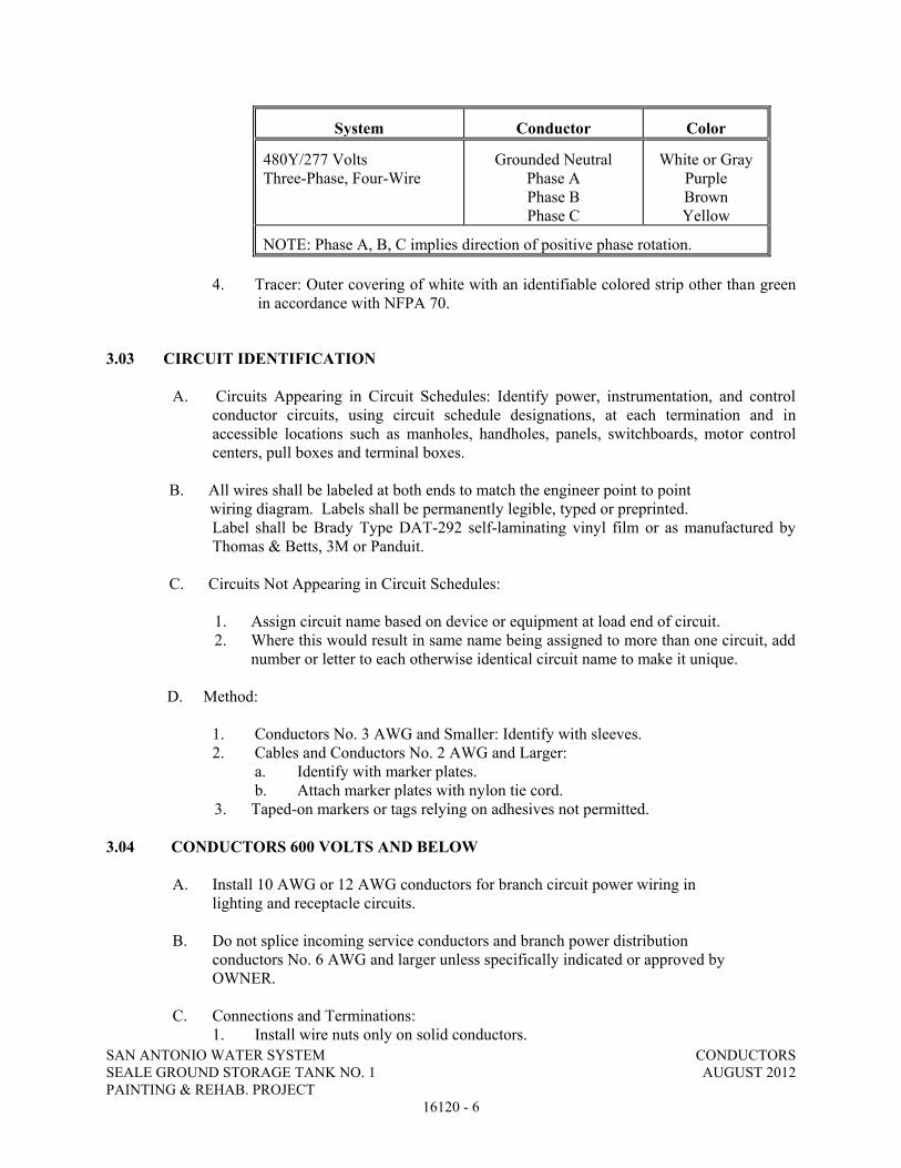
SAN ANTONIO WATER SYSTEM CONDUCTORS SEALE GROUND STORAGE TANK NO. 1 AUGUST 2012 PAINTING & REHAB. PROJECT
16120 - 6
System Conductor Color
480Y/277 Volts Three-Phase, Four-Wire
Grounded Neutral Phase A Phase B Phase C
White or Gray Purple Brown Yellow
NOTE: Phase A, B, C implies direction of positive phase rotation.
4. Tracer: Outer covering of white with an identifiable colored strip other than green in accordance with NFPA 70.
3.03 CIRCUIT IDENTIFICATION
A. Circuits Appearing in Circuit Schedules: Identify power, instrumentation, and control
conductor circuits, using circuit schedule designations, at each termination and in accessible locations such as manholes, handholes, panels, switchboards, motor control centers, pull boxes and terminal boxes.
B. All wires shall be labeled at both ends to match the engineer point to point wiring diagram. Labels shall be permanently legible, typed or preprinted.
Label shall be Brady Type DAT-292 self-laminating vinyl film or as manufactured by Thomas & Betts, 3M or Panduit.
C. Circuits Not Appearing in Circuit Schedules:
1. Assign circuit name based on device or equipment at load end of circuit. 2. Where this would result in same name being assigned to more than one circuit, add
number or letter to each otherwise identical circuit name to make it unique. D. Method: 1. Conductors No. 3 AWG and Smaller: Identify with sleeves. 2. Cables and Conductors No. 2 AWG and Larger: a. Identify with marker plates. b. Attach marker plates with nylon tie cord.
3. Taped-on markers or tags relying on adhesives not permitted. 3.04 CONDUCTORS 600 VOLTS AND BELOW A. Install 10 AWG or 12 AWG conductors for branch circuit power wiring in lighting and receptacle circuits. B. Do not splice incoming service conductors and branch power distribution
conductors No. 6 AWG and larger unless specifically indicated or approved by OWNER.
C. Connections and Terminations: 1. Install wire nuts only on solid conductors.
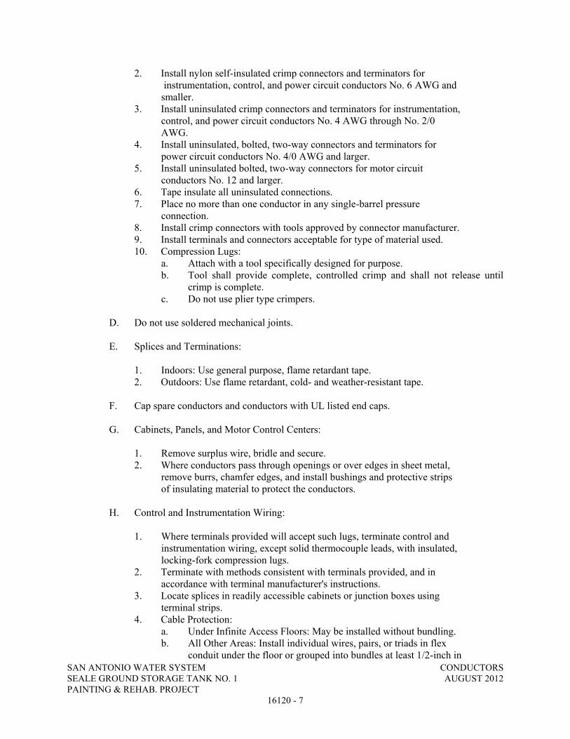
SAN ANTONIO WATER SYSTEM CONDUCTORS SEALE GROUND STORAGE TANK NO. 1 AUGUST 2012 PAINTING & REHAB. PROJECT
16120 - 7
2. Install nylon self-insulated crimp connectors and terminators for instrumentation, control, and power circuit conductors No. 6 AWG and smaller. 3. Install uninsulated crimp connectors and terminators for instrumentation, control, and power circuit conductors No. 4 AWG through No. 2/0 AWG. 4. Install uninsulated, bolted, two-way connectors and terminators for power circuit conductors No. 4/0 AWG and larger. 5. Install uninsulated bolted, two-way connectors for motor circuit conductors No. 12 and larger. 6. Tape insulate all uninsulated connections. 7. Place no more than one conductor in any single-barrel pressure connection. 8. Install crimp connectors with tools approved by connector manufacturer. 9. Install terminals and connectors acceptable for type of material used. 10. Compression Lugs: a. Attach with a tool specifically designed for purpose. b. Tool shall provide complete, controlled crimp and shall not release until
crimp is complete. c. Do not use plier type crimpers.
D. Do not use soldered mechanical joints. E. Splices and Terminations: 1. Indoors: Use general purpose, flame retardant tape.
2. Outdoors: Use flame retardant, cold- and weather-resistant tape. F. Cap spare conductors and conductors with UL listed end caps. G. Cabinets, Panels, and Motor Control Centers: 1. Remove surplus wire, bridle and secure.
2. Where conductors pass through openings or over edges in sheet metal, remove burrs, chamfer edges, and install bushings and protective strips of insulating material to protect the conductors.
H. Control and Instrumentation Wiring: 1. Where terminals provided will accept such lugs, terminate control and instrumentation wiring, except solid thermocouple leads, with insulated, locking-fork compression lugs.
2. Terminate with methods consistent with terminals provided, and in accordance with terminal manufacturer's instructions. 3. Locate splices in readily accessible cabinets or junction boxes using terminal strips. 4. Cable Protection: a. Under Infinite Access Floors: May be installed without bundling. b. All Other Areas: Install individual wires, pairs, or triads in flex conduit under the floor or grouped into bundles at least 1/2-inch in

SAN ANTONIO WATER SYSTEM CONDUCTORS SEALE GROUND STORAGE TANK NO. 1 AUGUST 2012 PAINTING & REHAB. PROJECT
16120 - 8
diameter. c. Maintain integrity of shielding of instrumentation cables. d. Ensure grounds do not occur because of damage to jacket over the shield. 5. Instrument shields shall be grounded at only one end.
I. Extra Conductor Length: For conductors to be connected by others, install minimum 6 feet of extra conductor in freestanding panels and minimum 2 feet in other assemblies. 3.05 CONDUCTOR ARC AND FIREPROOFING
A. Wrap conductors of same circuit entering from separate conduit together as a single cable.
B. Follow tape manufacturer's installation instructions.
C. Secure tape at intervals of 5 feet with bands of tape binder. Each band to consist of a minimum of two wraps directly over each other.
3.06 FIELD QUALITY CONTROL
A. In accordance with Section 16950, ELECTRICAL TESTING.
END OF SECTION

SAN ANTONIO WATER SYSTEM POWER SYSTEM STUDY SEALE GROUND STORAGE TANK NO. 1 AUGUST 2012 PAINTING & REHAB. PROJECT
16411-1
SECTION 16411 POWER SYSTEM STUDY
PART 1 GENERAL
1.01 DESCRIPTION
A. General: This section specifies that the CONTRACTOR provide short circuit and coordination studies including arc flash hazard study. Each electrical power system shall be deemed to include the utility company’s transformers and the OWNER’s power distribution system for this project. The short circuit, protective device coordination, and arc flash study reports shall provide an evaluation of the electrical power systems and the model numbers and settings of the protective devices for setting by the CONTRACTOR.
B. Scope:
1. Provide complete short circuit study, equipment interrupting or withstand evaluation, and a protective device coordination study for the power distribution systems. Normal system operating method, alternate operation, and operations which could result in maximum fault conditions shall be thoroughly addressed in the study. The study shall assume all motors operating at rated voltage. Electrical equipment bus impedance shall be assumed zero. Short circuit momentary duties and interrupting duties shall be calculated on the basis of maximum available fault current at the motor control centers.
2. A protective device coordination study shall be performed to determine appropriate relay settings. The study shall include all motor control centers, and panelboard main circuit breakers. Panelboard branch circuit devices need not be considered. The phase overcurrent and ground-fault protection shall be included as well as settings for all other adjustable protective devices.
3. An arc flash hazard study shall be performed based on the worst-case short circuit scenario. The study shall be performed in accordance with the latest version of IEEE Std 1584. Labels shall be provided for each covered piece of equipment for installation on the equipment. These labels will provide all necessary information for personnel to select the proper Personnel Protective Equipment (PPE). A one-line diagram shall be provided showing incident energy, flash protection boundary, and pertinent ratings.
4. An equipment evaluation study shall be performed to determine the adequacy of circuit breakers, controllers, surge arresters, busways, switches, and fuses by tabulating and comparing the short circuit ratings of these devices with the available fault currents.
5. Any problem areas or inadequacies in the equipment shall be promptly brought to the ENGINEER’s attention.
1.02 REFERENCES
A. This Section contains references to the following documents. They are part of this Section as specified and modified. In case of conflict between the requirements of this Section and those of the listed documents, the requirements of this Section shall prevail.

SAN ANTONIO WATER SYSTEM POWER SYSTEM STUDY SEALE GROUND STORAGE TANK NO. 1 AUGUST 2012 PAINTING & REHAB. PROJECT
16411-2
Reference Title
IEEE 141-86 Recommended Practice for Electric Power Distribution for Industrial Plants IEEE 242-86 Recommended Practice for Protection and Coordination of Industrial and Commercial Power Systems IEEE 1584-02 IEEE Guide For Performing Arc Flash
Hazard Calculations
1.03 SCHEDULE
A. The approved reports shall be completed and a copy sent to the electrical distribution equipment manufacturer 45 days before the equipment is shipped to the Work site. The report shall be provided to the ENGINEER 90 days before the equipment is shipped to the Work site.
PART 2 PRODUCTS
2.01 REPORTS
A. The product shall be a certified report summarizing the short circuit coordination study and conclusions or recommendations that may affect the integrity of the electric power distribution system. As a minimum, the report shall include the following:
1. The equipment manufacturer’s information used to prepare the study. 2. Assumptions made during the study. 3. Short circuit calculations listing short circuit levels at each bus. 4. Coordination study time-current curves including the instrument transformer
ratios, model numbers of the protective relays, and the relay settings associated with each breaker.
5. Comparison of short circuit duties of each bus to the interrupting capacity of the equipment protecting that bus.
6. All data that was used as input to the report. This data shall include cable impedances, source impedances, equipment ratings, etc.
PART 3 EXECUTION
3.01 GENERAL
A. Provide short circuit, coordination, and arc flash hazard studies on the electrical power distribution system, as specified. Each study shall be performed in accordance with IEEE Standards 141, 242, and 1584 and shall utilize the ANSI method of short circuit analysis in accordance with ANSI C37.010. Each study shall be performed using actual

SAN ANTONIO WATER SYSTEM POWER SYSTEM STUDY SEALE GROUND STORAGE TANK NO. 1 AUGUST 2012 PAINTING & REHAB. PROJECT
16411-3
equipment data for all equipment. Each coordination study shall use the data from the manufacturer of protective devices.
3.02 QUALIFICATIONS
A. Each report shall be performed by an electrical engineering or testing service that is regularly engaged in power system studies. A Professional Engineer, with proficiency in electrical engineering power studies, shall sign and seal the studies. The Professional Engineer shall be licensed to practice engineering in the State of Texas, with a minimum 5 years experience in system studies.
3.03 SHORT CIRCUIT STUDIES
A. The CONTRACTOR shall be responsible to obtain and verify all data needed to perform the studies.
B. As a minimum, each short circuit study shall include the following:
1. One-Line Diagram: a. Location and function of each protective device in the system, such as relays, direct acting trips, fuses, etc. b. Type designation, current rating, range or adjustment, manufacturer’s style and catalog number for all protective devices. c. Power, voltage ratings, impedance, primary and secondary connections of all transformers. d. Type, manufacturer, and ratio of all instrument transformers energizing each
relay. e. Nameplate ratings of all motors and generators with their subtransient
reactances. Transient reactances of synchronous motors and generators and synchronous reactances of all generators.
f. Sources of short circuit currents such as utility ties, generators, synchronous motors, and induction motors.
g. All significant circuit elements such as transformers, cables, breakers, fuses, reactors, etc.
h. Emergency as well as normal switch conditions. i. The time-current setting of existing adjustable relays and direct acting trips,
if applicable. 2. Impedance Diagram:
a. Available MVA or impedance from the utility company b. Local generated capacity impedance c. Bus impedance d. Transformer and/or reactor impedances e. Cable impedances f. Equipment impedances g. System voltages h. Ground scheme (resistance grounding, solid grounding, or no grounding)
3. Calculations: a. Determine the paths and situations where short circuit currents are the greatest. Assume bolted faults and calculate the 3-phase and line-to-ground short circuits of each case.

SAN ANTONIO WATER SYSTEM POWER SYSTEM STUDY SEALE GROUND STORAGE TANK NO. 1 AUGUST 2012 PAINTING & REHAB. PROJECT
16411-4
b. Calculate the maximum and minimum fault currents.
3.04 COORDINATION STUDY
A. As a minimum, the coordination study for the power distribution system shall include the following on 5-cycle, log-log graph paper.
1. Time-current curves for each protective relay or fuse showing graphically that the settings will provide protection and selectivity within industry standards. Each curve shall be identified, and the tap and time dial settings shall be specified.
2. Time-current curves for each device shall be positioned to provide for maximum selectivity to minimize system disturbances during fault clearing. Where selectivity cannot be achieved, the ENGINEER shall be notified as to the cause.
3. Time-current curves and points for cable and equipment damage. 4. Circuit interrupting device operating and interrupting times. 5. Indicated maximum fault values on the graph. 6. Sketch of bus and breaker arrangement.
3.05 ARC FLASH HAZARD STUDY
A. Colored labels shall be provided that contain:
1. Flash Hazard Boundary 2. Limited Approach Boundary 3. Restricted Boundary 4. Prohibited Boundary 5. Incident Energy Level 6. Required Personnel Protective Equipment Class 7. Type of Fire Rated Clothing
END OF SECTION

SAN ANTONIO WATER SYSTEM GROUND GRID, GROUNDING SEALE GROUND STORAGE TANK NO. 1 AND LIGHTNING PROTECTION PAINTING & REHAB. PROJECT AUGUST 2012 16451 - 1
SECTION 16451 GROUND GRID, GROUNDING AND LIGHTNING PROTECTION
PART 1 GENERAL
1.01 SUBMITTALS
A. Shop Drawings:
1. Product Data: a. Exothermic weld connectors b. Mechanical connectors c. Compression connectors d. Ground Rods e. Surge Arresters f. Conductors
1.02 UL COMPLIANCE
A. Materials manufactured within scope of Underwriters Laboratories shall conform to UL Standards and have an applied UL listing mark.
1.03 GROUNDING SYSTEM
A. The grounding system is a solidly grounded neutral system that is multigrounded. The grounding electrode is the grounding rings formed by the conductors encircling the equipment and/or structures.
PART 2 PRODUCTS
2.01 GROUND RODS
A. Located as shown on the grounding site plan.
B. Material: Copper Bonded.
C. Size: 3/4” x 10’
D. Ground Enhancement Material (GEM) backfill, if required.
E. Manufacturers: Erico, Inc.; ground rods and GEM backfill.
2.02 GROUND CONDUCTORS
A. Conductor size as shown on the grounding site plan.
B. As specified in Section 16120, CONDUCTORS.

SAN ANTONIO WATER SYSTEM GROUND GRID, GROUNDING SEALE GROUND STORAGE TANK NO. 1 AND LIGHTNING PROTECTION PAINTING & REHAB. PROJECT AUGUST 2012 16451 - 2
2.03 CONNECTORS
A. Exothermic Weld Type:
1. Outdoor Weld: Suitable for exposure to elements or direct burial. 2. Indoor Weld: Utilize low-smoke, low-emission process. 3. Manufacturers:
a. Erico Products, Inc.; Cadweld and Cadweld Exolon b. Thermoweld
B. Below Grade Compression Type:
1. Irreversible high strength compression. 2. Pure wrought copper extrusion. 3. Barrels prefilled with oxide-inhibiting and antiseizing compound and sealed. 4. Manufacturers:
a. Burndy Corp, hyground compression system
C. Above Grade Compression Type for Equipment Ground Connection:
1. Single indentation for conductors 6 AWG and smaller. 2. Double indentation with extended barrel for conductors 4 AWG and larger. 3. Barrels prefilled with oxide-inhibiting and antiseizing compound and sealed. 4. Specifically listed for ground connections 5. All mechanical hardware, nuts, bolts and washers shall be high strength copper
alloy. 6. Manufacturers:
a. Burndy Corp 2.04 LOW-VOLTAGE SURGE/LIGHTNING ARRESTORS
A. High-energy low voltage distribution class.
B. Light Duty distribution per ANSI/IEEE C62.11
C. Manufacturers:
1. Cooper Power System (Storm Trapper H.E.)
PART 3 EXECUTION
3.01 GENERAL
A. Grounding shall be in compliance with NEC Article 250, NFPA 70 and ANSI C2.
B. Ground each separately derived system neutral in accordance with NEC 250-30. All connections will be connected to the grounding grid.

SAN ANTONIO WATER SYSTEM GROUND GRID, GROUNDING SEALE GROUND STORAGE TANK NO. 1 AND LIGHTNING PROTECTION PAINTING & REHAB. PROJECT AUGUST 2012 16451 - 3
C. Bond together system neutrals, service equipment enclosures, exposed noncurrent-carrying metal parts of electrical equipment, metal raceways, ground conductor in raceways and cables, receptacle ground connections, and metal piping systems.
D. Arresters shall be installed in locations as shown on the Contract Drawings.
E. Shielded Instrumentation Cables:
1. Expose shield minimum 1 inch at termination to field instrument and apply heat shrink tube.
2. Do not ground instrumentation cable shield at more than one point.
F. Ground grid conductors to be installed not less than 30 inches deep.
3.02 WIRE CONNECTIONS
A. Ground Conductors: Install in conduit containing low voltage power conductors and control circuits above 50 volts.
B. Nonmetallic Raceways and Flexible Tubing: Install an equipment-grounding conductor connected at both ends to noncurrent carrying grounding bus.
C. Connect ground conductors to raceway grounding bushings.
D. Extend and connect ground conductors to ground bus in all equipment containing a ground bus.
E. Connect enclosure of equipment containing ground bus to that bus.
F. Bolt connections to equipment ground bus.
G. Bond grounding conductors to metallic enclosures at each end, and to intermediate metallic enclosures.
H. Junction Boxes: Furnish materials and connect to equipment grounding system with grounding clips mounted directly on box, or with 3/8-inch machine screws.
3.03 MOTOR GROUNDING
A. Motor frame shall be connected to the ground grid as indicated on the grounding site plan.
B. Nonmetallic Raceways and Flexible Tubing: Install an equipment-grounding conductor connected at both ends to noncurrent carrying grounding bus.
C. Motors Less Than 10 hp: Furnish compression, spade-type terminal connected to conduit box mounting screw.
D. Circuits 20 Amps or above: Tap motor frame or equipment housing; install solderless terminal with minimum 5/16-inch diameter bolt.

SAN ANTONIO WATER SYSTEM GROUND GRID, GROUNDING SEALE GROUND STORAGE TANK NO. 1 AND LIGHTNING PROTECTION PAINTING & REHAB. PROJECT AUGUST 2012 16451 - 4
3.04 GROUND RODS
A. Install ground rod full length with conductor connection at upper end. The ground rod shall be driven into undisturbed earth.
B. If soil conditions prevent driving the ground rod to full length, installation shall by accomplished by augering a 3” diameter or larger hole and backfilling with compacted ground enhancement material.
C. Install top of rod 6 inches below finished grade, unless otherwise shown.
3.05 CONNECTIONS
A. General:
1. Above Grade Connections: Use either exothermic weld, mechanical, or compression-type connectors.
2. Below Grade Connections: Install exothermic weld or compression type connectors. a. Remove paint, dirt, or other surface coverings at connection points to allow
good metal-to-metal contact. b. Notify OWNER prior to backfilling ground connections.
B. Exothermic Weld Type:
1. Wire brush or file contact point to bare metal surface. 2. Use welding cartridges and molds in accordance with manufacturer's
recommendations. 3. Do not use badly worn molds. 4. Mold to be completely filled with metal when making welds. 5. After completed welds have cooled, brush slag from weld area and thoroughly
clean joint.
C. Compression Type:
1. Install in accordance with connector manufacturer's recommendations. 2. Install connectors of proper size for grounding conductors and ground rods
specified. 3. Install using connector manufacturer's compression tool having proper sized dies.
D. Mechanical Type:
1. Apply homogeneous blend of colloidal copper and rust and corrosion inhibitor before making connection.
2. Install in accordance with connector manufacturer's recommendations. 3. Do not conceal mechanical connections.
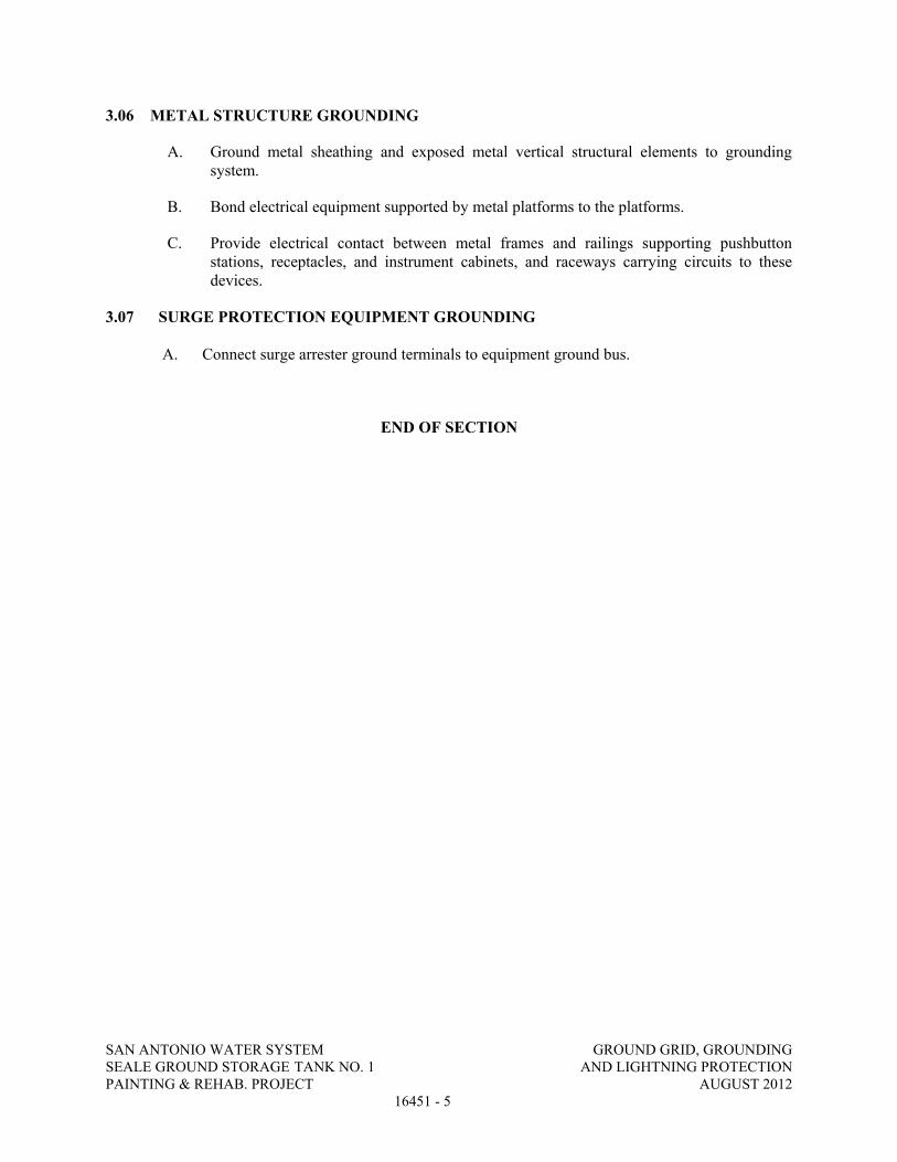
SAN ANTONIO WATER SYSTEM GROUND GRID, GROUNDING SEALE GROUND STORAGE TANK NO. 1 AND LIGHTNING PROTECTION PAINTING & REHAB. PROJECT AUGUST 2012 16451 - 5
3.06 METAL STRUCTURE GROUNDING
A. Ground metal sheathing and exposed metal vertical structural elements to grounding system.
B. Bond electrical equipment supported by metal platforms to the platforms.
C. Provide electrical contact between metal frames and railings supporting pushbutton stations, receptacles, and instrument cabinets, and raceways carrying circuits to these devices.
3.07 SURGE PROTECTION EQUIPMENT GROUNDING
A. Connect surge arrester ground terminals to equipment ground bus.
END OF SECTION

SAN ANTONIO WATER SYSTEM INSTRUMENTATION SEALE GROUND STORAGE TANK NO. 1 AUGUST 2012 PAINTING & REHAB. PROJECT
16930 - 1
SECTION 16930 INSTRUMENTATION
PART 1 GENERAL 1.01 SCOPE
A. Contractor General Qualifications 1. Contractor shall have a minimum of five years experience installing and
commissioning instrumentation systems. 2. Provide resumes, project experience history and references for all employees that will
be qualified to work on the Instrumentation installation, calibration and testing. 3. All proposals submitted to the San Antonio Water System must be accompanied by
documentation supporting the qualifications of the contractor as detailed above. The San Antonio Water System reserves the right to reject any proposal if the above qualifications are not met.
B. Contractor shall furnish, install, calibrate and test instrumentation for
monitoring and control, for the following process functions:
1. Level (By Pressure) 2. Level (By Electrodes) 3. Flow 4. Pressure
1.02 SUBMITTALS
A. Shop Drawings:
1. Bill of Materials 2. Catalog Cuts 3. Component Data Sheets
PART 2 PRODUCTS 2.01 GENERAL
A. Hardware:
1. All hardware used for outdoor instrument mounting shall be Stainless Steel or Double Dipped Galvanized steel.
B. Process Pipe:
1. All tubing and fitting shall be made of 316 Stainless Steel.
2.02 PRESSURE TRANSMITTER (TANK LEVEL)
A. Electronic Gage Pressure Transmitter:

SAN ANTONIO WATER SYSTEM INSTRUMENTATION SEALE GROUND STORAGE TANK NO. 1 AUGUST 2012 PAINTING & REHAB. PROJECT
16930 - 2
1. Local and remote indication. 2. Provide with Ray self-cleaning pressure snubbers. 3. Input isolated with silicone filled stainless steel diaphragms. 4. Local indication LCD meter scaled in FEET and mounted integral to the transmitter.
Transmitter operation ranges should operate at bottom 25% of full-scale range of transmitter.
5. Outdoor application: a. NEMA 4 housing b. View port for local indication c. Stainless steel flanges d. 2” pipe mount
B. Ratings:
1. Overpressure Limit without damage: 1500 psi 2. Input Range: 150 psi 3. Accuracy: +/- 0.075% of span 4. Analog Output: 4 – 20 mA 5. Power Supply: 24 Vdc 6. Operating Temperature Limits: -4° to 175°F
C. Manufacturer: Rosemount, Model: 2088, Model Number 2088G2S22A1B4DWM7. 2.03 FLOW TRANSMITTER
A. Electromagnetic Flow Tube and Transmitter.
1. Electromagnetic. 2. Indication at transmitter. 3. Shall be provided with external surge suppression equipment to protect 120 VAC
input 4-20mA output and Modbus RS485 output. 4. 4-20mA output. 5. Modbus RS485 output. 6. NSF61 rated or equivalent. 7. Equipment supplied must be 100% compatible with Modbus Protocol and suitable
for conversion at a later date for Profibus or Foundation Fieldbus. 8. Totalizer readings shall be in MG and interface directly with Modbus based
monitoring and control systems. Flow readings shall be in MGD.
B. Ratings: 1. Minimum accuracy required: +/- 2.0%. 2. Power supply: 110 – 120 Vac 3. Ambient temperature: -5° – 140°F
C. Manufacturer: Endress & Hauser, see model number selection below. Endress & Hauser
to also supply the following: 1. One (1) Modem/Communicator Box, Model FXA 193-AA.

SAN ANTONIO WATER SYSTEM INSTRUMENTATION SEALE GROUND STORAGE TANK NO. 1 AUGUST 2012 PAINTING & REHAB. PROJECT
16930 - 3
2. Associated Field check/Field Care software (1 copy - See section 3.01.D in this specification, 16930).
0 1 2 3 4 5 6 7 8 9 10 11 12 Promag 53W * * U L G B 1 A C * B A A N * Option is site specific. Refer to project plans for selection. 0 Nominal Diameter 2H 8" 2F 10" 3H 12" 3F 14" 4H 16" 4F 18" 5H 20" 6H 24" 7H 28" 7F 30", AWWA 1 Liner U Polyurethane 2 Process Connection
L
Class 150 ANSI B16.5 CS steel A105 flanges (P for over 24")
3 Electrodes/material
G
Measuring, reference and EPD electrodes, bullet nose/316LSS
4 Calibration B 3-point calibration, 0.2% 5 Certificates 1 Standard, no certificate 6 Approvals A For use in non-hazardous areas 7 Housing
C
NEMA 4X (IP 67) remote wall-mounted (only for approvals A or R )
8 Cable for remote 0 Without cable 1 15 foot coil and signal cable 2 30 foot coil and signal cable.
5
Coil and signal cable, specify length (maximum 650 ft depending on conductivity of process material)
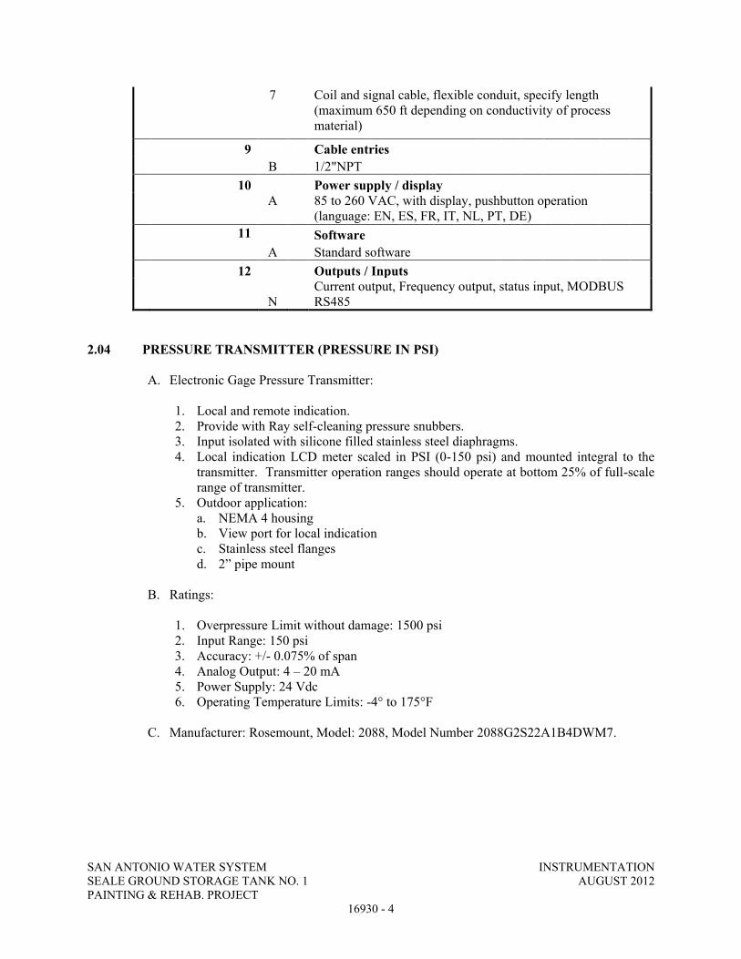
SAN ANTONIO WATER SYSTEM INSTRUMENTATION SEALE GROUND STORAGE TANK NO. 1 AUGUST 2012 PAINTING & REHAB. PROJECT
16930 - 4
7
Coil and signal cable, flexible conduit, specify length (maximum 650 ft depending on conductivity of process material)
9 Cable entries B 1/2"NPT 10 Power supply / display
A
85 to 260 VAC, with display, pushbutton operation (language: EN, ES, FR, IT, NL, PT, DE)
11 Software A Standard software 12 Outputs / Inputs
N Current output, Frequency output, status input, MODBUS RS485
2.04 PRESSURE TRANSMITTER (PRESSURE IN PSI)
A. Electronic Gage Pressure Transmitter:
1. Local and remote indication. 2. Provide with Ray self-cleaning pressure snubbers. 3. Input isolated with silicone filled stainless steel diaphragms. 4. Local indication LCD meter scaled in PSI (0-150 psi) and mounted integral to the
transmitter. Transmitter operation ranges should operate at bottom 25% of full-scale range of transmitter.
5. Outdoor application: a. NEMA 4 housing b. View port for local indication c. Stainless steel flanges d. 2” pipe mount
B. Ratings:
1. Overpressure Limit without damage: 1500 psi 2. Input Range: 150 psi 3. Accuracy: +/- 0.075% of span 4. Analog Output: 4 – 20 mA 5. Power Supply: 24 Vdc 6. Operating Temperature Limits: -4° to 175°F
C. Manufacturer: Rosemount, Model: 2088, Model Number 2088G2S22A1B4DWM7.
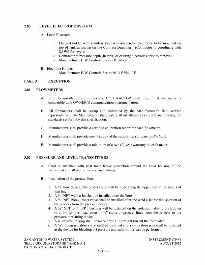
SAN ANTONIO WATER SYSTEM INSTRUMENTATION SEALE GROUND STORAGE TANK NO. 1 AUGUST 2012 PAINTING & REHAB. PROJECT
16930 - 5
2.05 LEVEL ELECTRODE SYSTEM
A. Level Electrode:
1. Flanged holder with stainless steel wire-suspended electrodes to be mounted on top of tank as shown on the Contract Drawings. (Contractor to coordinate with SAWS for levels)
2. Contractor to measure depth (in tank) of existing electrodes prior to removal. 3. Manufacturer: B/W Controls Series 6013-W2.
B. Electrode Holder:
1. Manufacturer: B/W Controls Series 6012-E554-13E
PART 3 EXECUTION 3.01 FLOWMETERS
A. Prior to installation of the meters, CONTRACTOR shall insure that the meter is
compatible with OWNER’S communication instrumentation.
B. All flowmeters shall be set-up and calibrated by the Manufacturer’s field service representative. The Manufacturer shall certify all installations as correct and meeting the standards set forth by this specification.
C. Manufacturer shall provide a certified calibration report for each flowmeter.
D. Manufacturer shall provide one (1) copy of the calibration software to OWNER.
E. Manufacturer shall provide a minimum of a two (2) year warranty on each meter.
3.02 PRESSURE AND LEVEL TRANSMITTERS
A. Shall be installed with heat trace freeze protection around the fluid housing of the instrument and all piping, valves, and fittings.
B. Installation of the process line:
1. A ½” bore through the process line shall be done along the upper half of the radius of
that line. 2. A ½” NPT weld a-let shall be installed over the bore 3. A ½” NPT block (root) valve shall be installed after the weld a-let for the isolation of
the process from the pressure device. 4. A ½” NPT to ¼” NPT bushing will be installed on the isolation valve to bush down
to allow for the installation of ¼” static or process lines from the process to the pressure measuring device.
5. A 4” expansion loop shall be made after a 1’ straight run off the root valve. 6. A ¼” tubing isolation valve shall be installed and a calibration port shall be installed
at the device for bleeding off pressure and calibrations can be performed.
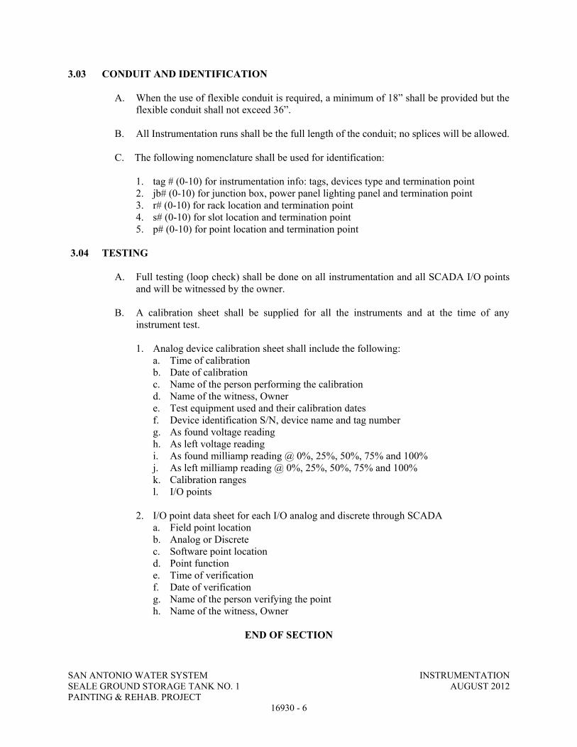
SAN ANTONIO WATER SYSTEM INSTRUMENTATION SEALE GROUND STORAGE TANK NO. 1 AUGUST 2012 PAINTING & REHAB. PROJECT
16930 - 6
3.03 CONDUIT AND IDENTIFICATION
A. When the use of flexible conduit is required, a minimum of 18” shall be provided but the flexible conduit shall not exceed 36”.
B. All Instrumentation runs shall be the full length of the conduit; no splices will be allowed. C. The following nomenclature shall be used for identification:
1. tag # (0-10) for instrumentation info: tags, devices type and termination point 2. jb# (0-10) for junction box, power panel lighting panel and termination point 3. r# (0-10) for rack location and termination point 4. s# (0-10) for slot location and termination point 5. p# (0-10) for point location and termination point
3.04 TESTING
A. Full testing (loop check) shall be done on all instrumentation and all SCADA I/O points and will be witnessed by the owner.
B. A calibration sheet shall be supplied for all the instruments and at the time of any
instrument test.
1. Analog device calibration sheet shall include the following: a. Time of calibration b. Date of calibration c. Name of the person performing the calibration d. Name of the witness, Owner e. Test equipment used and their calibration dates f. Device identification S/N, device name and tag number g. As found voltage reading h. As left voltage reading i. As found milliamp reading @ 0%, 25%, 50%, 75% and 100% j. As left milliamp reading @ 0%, 25%, 50%, 75% and 100% k. Calibration ranges l. I/O points
2. I/O point data sheet for each I/O analog and discrete through SCADA a. Field point location b. Analog or Discrete c. Software point location d. Point function e. Time of verification f. Date of verification g. Name of the person verifying the point h. Name of the witness, Owner
END OF SECTION

SAN ANTONIO WATER SYSTEM INSTRUMENTATION HEAT TRACE SYSTEM SEALE GROUND STORAGE TANK NO. 1 AUGUST 2012 PAINTING & REHAB. PROJECT
16940 - 1
SECTION 16940
INSTRUMENTATION HEAT TRACE SYSTEM
PART 1 GENERAL
1.01 DESCRIPTION OF WORK
A. Furnish and install thermostatically controlled heat trace system for freeze protection.
B. The system shall include controls, control cabinet, cable, insulation and jacket as indicated on the Contract Drawings and as specified hereinafter.
C. Furnish and install all weather-tight LB fittings, liquid-tight connectors, liquid-tight flexible metal conduit and wiring, etc, to provide power and controls for a complete operating system.
D. Items to be protected by heat trace include: 1. Instrument fluid housings and all associated piping, valves, fittings, etc.
1.02 SUBMITTALS
A. Heat trace cable.
B. Heat trace cable insulation and jacket.
C. Heat trace thermostat.
D. Heat trace panel wiring.
PART 2 PRODUCTS
2.01 HEAT TRACE CABLE
A. Heat cable shall be U.L. listed, self-regulating, with additional footage at all valves, instruments, and pipe supports, as recommended by the manufacturer. Maximum circuit lengths shall be in accordance with the manufacturer’s recommendations.
B. Manufacturer: Heat cable shall be Raychem “5BTV1”, 6 watts/ft at 40°F for operation at 120 volts, or equal product as manufactured by Chromalox or Thermon.
2.02 HEAT TRACE CABLE INSULATION AND JACKET
A. The insulation shall be preformed cellular glass insulation, 1” thick minimum, non-absorptive, impermeable to moisture and impervious to hydrochloric acid.
B. A weather-resistant, watertight, protective finish or jacket shall be applied over all insulation as recommended and manufactured by the insulation manufacturer.
C. Manufacturer: Heat trace insulation shall be Pittsburg Corning “Foamglas”, Armstrong Armaflex II pipe insulation, or approved equal.

SAN ANTONIO WATER SYSTEM INSTRUMENTATION HEAT TRACE SYSTEM SEALE GROUND STORAGE TANK NO. 1 AUGUST 2012 PAINTING & REHAB. PROJECT
16940 - 2
2.03 HEAT TRACE THERMOSTAT (HTT) AND CONTACTOR (HTC)
A. Heat trace circuits shall be switched through a thermostat, set at 40°F, and a multipole contactor (HTC) as indicated on the Contract Drawings. The contactor shall be NEMA rated, 20 ampere, 120 volts, multipole, with 120-volt control coil. The thermostat shall be weatherproof, line-type, 120 volts.
B. Manufacturer: Heat trace thermostat shall be Thermon model B4X.
PART 3 EXECUTION
3.01 HEAT TRACE CABLE
A. Spiral the heat cable around the pipe, criss-cross around valves, and attach cable to pipe with GT-66 glass fiber adhesive tape or plastic tie wraps.
B. All power connections to heat trace cable shall be made in watertight j-boxes or with power connection kits recommended by the cable manufacturer. Tees, splices, terminations, and cable shall be of the same manufacturer.
3.02 HEAT TRACE CABLE INSULATION
A. Install insulation over the entire length of piping protected with heat cable. Insulation shall be mitered and nested to cover all tees, fittings, supports, valves, etc. Fitting covers may be preformed or field fabricated. The inner bore and joint surfaced shall be coated to fill the surface cells, and all joints shall be sealed as recommended by the manufacturer and secured in place with ½” wide stainless steel bands.
END OF SECTION
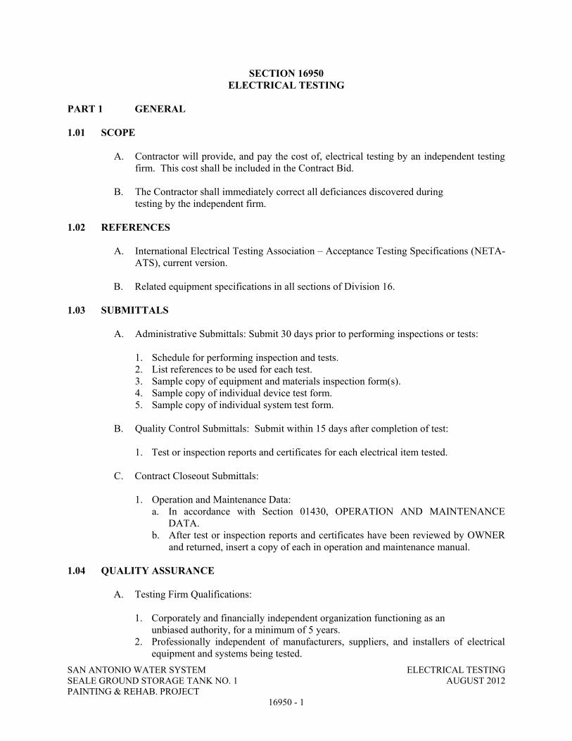
SAN ANTONIO WATER SYSTEM ELECTRICAL TESTING SEALE GROUND STORAGE TANK NO. 1 AUGUST 2012 PAINTING & REHAB. PROJECT
16950 - 1
SECTION 16950 ELECTRICAL TESTING
PART 1 GENERAL 1.01 SCOPE
A. Contractor will provide, and pay the cost of, electrical testing by an independent testing
firm. This cost shall be included in the Contract Bid. B. The Contractor shall immediately correct all deficiances discovered during
testing by the independent firm. 1.02 REFERENCES
A. International Electrical Testing Association – Acceptance Testing Specifications (NETA-ATS), current version.
B. Related equipment specifications in all sections of Division 16. 1.03 SUBMITTALS
A. Administrative Submittals: Submit 30 days prior to performing inspections or tests:
1. Schedule for performing inspection and tests. 2. List references to be used for each test. 3. Sample copy of equipment and materials inspection form(s). 4. Sample copy of individual device test form. 5. Sample copy of individual system test form.
B. Quality Control Submittals: Submit within 15 days after completion of test:
1. Test or inspection reports and certificates for each electrical item tested.
C. Contract Closeout Submittals:
1. Operation and Maintenance Data: a. In accordance with Section 01430, OPERATION AND MAINTENANCE
DATA. b. After test or inspection reports and certificates have been reviewed by OWNER
and returned, insert a copy of each in operation and maintenance manual. 1.04 QUALITY ASSURANCE
A. Testing Firm Qualifications:
1. Corporately and financially independent organization functioning as an unbiased authority, for a minimum of 5 years.
2. Professionally independent of manufacturers, suppliers, and installers of electrical equipment and systems being tested.

SAN ANTONIO WATER SYSTEM ELECTRICAL TESTING SEALE GROUND STORAGE TANK NO. 1 AUGUST 2012 PAINTING & REHAB. PROJECT
16950 - 2
3. Employer of engineers and technicians regularly engaged in testing and inspecting electrical equipment, installations, and systems.
4. Supervising technician having a minimum of 5 years testing experience on similar projects.
5. Full-time employed Registered Professional Engineer to provide comprehensive project report outlining services performed, results of such services, recommendations, actions taken, and opinions.
B. Test equipment shall have an operating accuracy equal to, or greater than,
requirements established at NETA-ATS.
C. Test instrument calibration shall be in accordance with NETA-ATS. 1.05 SEQUENCE AND SCHEDULING
A. Perform inspection and electrical tests after equipment has been installed.
B. Perform tests with apparatus de-energized whenever feasible.
C. Inspection and electrical tests on energized equipment are to be:
1. Scheduled with OWNER prior to de-energization. 2. Minimized to avoid extended period of interruption to the operating plant equipment.
D. Notify OWNER at least 24 hours prior to performing tests on energized
electrical equipment. PART 2 PRODUCTS – NOT USED
PART 3 EXECUTION 3.01 GENERAL
A. Tests specified in this section are to be performed in accordance with the requirements of Section 01651, FACILITY STARTUP.
B. Tests and inspection shall establish that:
1. Electrical equipment is operational within industry and manufacturer’s
tolerances. 2. Installation operates properly. 3. Equipment is suitable for energization. 4. Installation conforms to requirements of Contract Documents and NFPA 70, NFPA
70E, and ANSI C2.
C. Perform inspection and testing in accordance with NETA-ATS, industry standards, and manufacturer’s recommendations.

SAN ANTONIO WATER SYSTEM ELECTRICAL TESTING SEALE GROUND STORAGE TANK NO. 1 AUGUST 2012 PAINTING & REHAB. PROJECT
16950 - 3
D. Set, test, and calibrate protective relays, circuit breakers, and other applicable devices in accordance with standard values established by a short circuit and coordination study provided by CONTRACTOR.
E. Adjust mechanisms and moving parts for free mechanical movement.
F. Adjust adjustable relays and sensors to correspond to operating conditions, or as
recommended by manufacturer.
G. Verify nameplate data for conformance to Contract Documents.
H. Tighten accessible bolted connections, including wiring connections, with calibrated torque wrench to manufacturer’s recommendations, or as otherwise specified.
I. Clean contaminated surfaces with cleaning solvents as recommended by manufacturer.
J. Provide proper lubrication of applicable moving parts.
K. Inform OWNER of working clearances not in accordance with NFPA 70.
3.02 LOW VOLTAGE CABLES, 600 VOLTS MAXIMUM
A. Visual and Mechanical Inspection:
1. Inspect Each Individual Exposed Power Cable No. 4 and Larger for: a. Physical damage. b. Proper connections in accordance with single-line diagram. c. Cable bends not in conformance with manufacturer’s minimum allowable
bending radius where applicable. d. Color-coding conformance with specifications. e. Proper circuit identification.
2. Mechanical Connections For: a. Proper lug type for conductor material. b. Proper lug installation. c. Bolt torque level in accordance with NETA-ATS, Table 10.12, unless otherwise
specified by manufacturer. 3. Shielded Instrumentation Cables For:
a. Proper shield grounding. b. Proper terminations. c. Proper circuit identification.
4. Control Cables For: a. Proper termination. b. Proper circuit identification.
5. Cables Terminated Through Window Type CTs: Verify that neutrals and grounds are terminated for correct operation of protective devices.
B. Electrical Tests for Conductors No. 4 and Larger:
1. Insulation Resistance Tests: a. Utilize 1,000-volt dc megohmmeter for 600-volt insulated conductors.

SAN ANTONIO WATER SYSTEM ELECTRICAL TESTING SEALE GROUND STORAGE TANK NO. 1 AUGUST 2012 PAINTING & REHAB. PROJECT
16950 - 4
b. Test each conductor with respect to ground and to adjacent conductors per IEEE 118 procedures for 1 minute.
c. Evaluate ohmic values by comparison with conductors of same length and type. d. Investigate values less than 50 megohms.
2. Continuity test by ohmmeter method to ensure proper cable connections. 3.03 MOLDED AND INSULATED CASE CIRCUIT BREAKERS
A. General: Inspection and testing limited to circuit breakers rated 100 amperes and larger and to motor circuit protector breakers rated 50 amperes and larger.
B. Visual and Mechanical Inspection:
1. Proper mounting. 2. Proper conductor size. 3. Feeder designation according to nameplate and one-line diagram. 4. Cracked casings. 5. Connection bolt torque level in accordance with NETA-ATS, Table 10.12. 6. Operate breaker to verify smooth operation. 7. Compare frame size and trip setting with circuit breaker schedules or one-line
diagram. 8. Verify that terminals are suitable for 75°C rated insulated conductors.
3.04 METERING AND INSTRUMENTATION:
A. Visual and Mechanical/Electrical Inspection:
1. Verify meter and instrument connections in accordance with appropriate diagrams. 2. Verify meter multipliers. 3. Verify that meter and instrument types and scales conform to Contract Documents. 4. Check calibration of meters at cardinal points. 5. Check calibration of transducers and transmitters. 6. Check set-point and operation of pressure switches. 7. Verify operation of heat trace systems.
3.05 SUPERVISORY CONTROL AND DATA ACQUISITION (SCADA)
A. Visual and Mechanical Inspection: 1. Verify System Wiring:
a. Compare wiring to elementary diagrams. b. Check for proper conductor lacing and bundling. c. Check for proper conductor identification. d. Check lugs and terminations.
2. Verify labels and nameplates. 3. Verify component equipment and instrumentation conforms to Contract Documents. 4. Verify component electrical and mechanical connections conform to manufacturer’s
instructions.

SAN ANTONIO WATER SYSTEM ELECTRICAL TESTING SEALE GROUND STORAGE TANK NO. 1 AUGUST 2012 PAINTING & REHAB. PROJECT
16950 - 5
B. Operational Testing:
1. Check each control panel display and switch for proper control loop function.
2. Verify each Input/Output point from the end element to the remote central operations center.
3. Verify calibration and scale of each analog quantity. 4. Verify performance of uniterruptible power supply. Verify on-battery voltage and
waveform. 5. Verify operation of packaged radio back-up battery.
3.06 GROUNDING SYSTEMS
A. Visual and Mechanical Inspection: 1. Equipment and circuit grounds in motor control centers and switchgear
assemblies for proper connection and tightness. 2. Ground bus connections in motor control centers and switchgear
assemblies for proper termination and tightness. 3. Effective transformer core and equipment grounding. 4. Accessible connections to grounding electrodes for proper fit and tightness. 5. Accessible exothermic-weld grounding connections to verify that molds were fully
filled and proper bonding was obtained.
B. Electrical Tests: 1. Fall-Of-Potential Test:
a. In accordance with IEEE 81, Section 8.2.1.5 for measurement of main ground system’s resistance.
b. Main ground electrode system resistance to ground to be no greater than 20 ohms when disconnected from the utility company ground system.
3.07 THERMOGRAPHIC SURVEY
A. General:
1. Equipment to be inspected shall include all current-carrying devices including switchgear, switchboards, panelboards, breakers, fuse holders, switches and bus connections/joints.
B. Visual and Mechanical Inspection:
1. Perform thermographic survey when load is applied to the system. 2. Remove all necessary covers prior to thermographic inspection. Use appropriate
caution, safety devices, and personal protective equipment. 3. Perform a follow-up thermographic survey within 12 months of final acceptance by
the owner. C. Report:

SAN ANTONIO WATER SYSTEM ELECTRICAL TESTING SEALE GROUND STORAGE TANK NO. 1 AUGUST 2012 PAINTING & REHAB. PROJECT
16950 - 6
1. Provide a report which includes the following:
a. Description of equipment tested. b. Discrepancies. c. Temperature difference between the area of concern and the reference area. d. Probable cause of temperature difference. e. Areas inspected. Identify inaccessible and/or unobservable areas and/or
equipment. f. Identify load conditions at time of inspection. g. Provide photographs and/or thermograms of the deficient area. h. Recommended action.
D. Test Parameters: 1. Inspect distribution systems with imaging equipment capable of detecting a minimum
temperature difference of 1° C at 30° C. 2. Equipment shall detect emitted radiation and convert detected radiation to visual
signal. 3. Thermographic surveys should be performed during periods of maximum possible
loading. Refer to ANSI/NFPA 70B, Section 20.17.
END OF SECTION


Project: Seale Pump Station
Project Number: 131-09308-11003
Project Manager: Josh Sherman
Reported:Tetra Tech
700 N. Saint Marys Suite 300 10/11/11 15:51
San Antonio TX, 78205
Report No. 1109332
Cert. No. T104704360-11-5
Received:
09/30/11 16:15
Sample ID #: Interior Wet area by Ladder Hatch
Sample Matrix: Paint Chips
Sampling Method:
Date/Time Collected: 09/15/11 11:00
Lab Sample ID #: 1109332-01
Analyte Result PQL Batch Analyzed MethodUnits Analyst NotesPrep Method
Total Metals
10/05/11 18:270.500 B141031 601026.5 mg/kg wet IDCadmium * 3050B
10/06/11 13:595.00 B141031 6010557 mg/kg wet IDChromium * 3050B
10/05/11 18:271.00 B141031 601030.1 mg/kg wet IDLead * 3050B
1610 S. Laredo Street, San Antonio, Texas 78207-7029 (210) 229-9920 Fax (210) 229-9921www.satestinglab.com Page 1 of 26

Project: Seale Pump Station
Project Number: 131-09308-11003
Project Manager: Josh Sherman
Reported:Tetra Tech
700 N. Saint Marys Suite 300 10/11/11 15:51
San Antonio TX, 78205
Report No. 1109332
Cert. No. T104704360-11-5
Received:
09/30/11 16:15
Sample ID #: SW Exterior Roof
Sample Matrix: Paint Chips
Sampling Method:
Date/Time Collected: 09/15/11 11:10
Lab Sample ID #: 1109332-02
Analyte Result PQL Batch Analyzed MethodUnits Analyst NotesPrep Method
Total Metals
10/05/11 00:410.500 B141031 6010<0.500 mg/kg wet IDCadmium * 3050B
10/05/11 00:411.00 B141031 60101.53 mg/kg wet IDChromium * 3050B
10/05/11 00:411.00 B141031 60101.52 mg/kg wet IDLead * 3050B
1610 S. Laredo Street, San Antonio, Texas 78207-7029 (210) 229-9920 Fax (210) 229-9921www.satestinglab.com Page 2 of 26

Project: Seale Pump Station
Project Number: 131-09308-11003
Project Manager: Josh Sherman
Reported:Tetra Tech
700 N. Saint Marys Suite 300 10/11/11 15:51
San Antonio TX, 78205
Report No. 1109332
Cert. No. T104704360-11-5
Received:
09/30/11 16:15
Sample ID #: Exterior Shell @ Overflow
Sample Matrix: Paint Chips
Sampling Method:
Date/Time Collected: 09/15/11 11:15
Lab Sample ID #: 1109332-03
Analyte Result PQL Batch Analyzed MethodUnits Analyst NotesPrep Method
Total Metals
10/05/11 00:460.500 B141031 60100.540 mg/kg wet IDCadmium * 3050B
10/05/11 00:461.00 B141031 60103.85 mg/kg wet IDChromium * 3050B
10/05/11 00:461.00 B141031 60102.73 mg/kg wet IDLead * 3050B
1610 S. Laredo Street, San Antonio, Texas 78207-7029 (210) 229-9920 Fax (210) 229-9921www.satestinglab.com Page 3 of 26

Project: Seale Pump Station
Project Number: 131-09308-11003
Project Manager: Josh Sherman
Reported:Tetra Tech
700 N. Saint Marys Suite 300 10/11/11 15:51
San Antonio TX, 78205
Report No. 1109332
Cert. No. T104704360-11-5
Received:
09/30/11 16:15
Sample ID #: HSP Pump 2
Sample Matrix: Paint Chips
Sampling Method:
Date/Time Collected: 09/15/11 11:20
Lab Sample ID #: 1109332-04
Analyte Result PQL Batch Analyzed MethodUnits Analyst NotesPrep Method
Total Metals
10/05/11 00:520.500 B141031 60103.61 mg/kg wet IDCadmium * 3050B
10/05/11 00:521.00 B141031 601016.6 mg/kg wet IDChromium * 3050B
10/05/11 00:521.00 B141031 601015.3 mg/kg wet IDLead * 3050B
1610 S. Laredo Street, San Antonio, Texas 78207-7029 (210) 229-9920 Fax (210) 229-9921www.satestinglab.com Page 4 of 26

Project: Seale Pump Station
Project Number: 131-09308-11003
Project Manager: Josh Sherman
Reported:Tetra Tech
700 N. Saint Marys Suite 300 10/11/11 15:51
San Antonio TX, 78205
Report No. 1109332
Cert. No. T104704360-11-5
Received:
09/30/11 16:15
Sample ID #: HSP Pump 3
Sample Matrix: Paint Chips
Sampling Method:
Date/Time Collected: 09/19/11 08:00
Lab Sample ID #: 1109332-05
Analyte Result PQL Batch Analyzed MethodUnits Analyst NotesPrep Method
Total Metals
10/05/11 18:390.500 B141031 601034.3 mg/kg wet IDCadmium * 3050B
10/06/11 14:045.00 B141031 6010487 mg/kg wet IDChromium * 3050B
10/05/11 18:391.00 B141031 601073.4 mg/kg wet IDLead * 3050B
1610 S. Laredo Street, San Antonio, Texas 78207-7029 (210) 229-9920 Fax (210) 229-9921www.satestinglab.com Page 5 of 26

Project: Seale Pump Station
Project Number: 131-09308-11003
Project Manager: Josh Sherman
Reported:Tetra Tech
700 N. Saint Marys Suite 300 10/11/11 15:51
San Antonio TX, 78205
Report No. 1109332
Cert. No. T104704360-11-5
Received:
09/30/11 16:15
Sample ID #: HSP Pump 1
Sample Matrix: Paint Chips
Sampling Method:
Date/Time Collected: 09/19/11 08:05
Lab Sample ID #: 1109332-06
Analyte Result PQL Batch Analyzed MethodUnits Analyst NotesPrep Method
Total Metals
10/05/11 18:440.500 B141031 601021.8 mg/kg wet IDCadmium * 3050B
10/05/11 18:441.00 B141031 6010117 mg/kg wet IDChromium * 3050B
10/05/11 18:441.00 B141031 601028.0 mg/kg wet IDLead * 3050B
1610 S. Laredo Street, San Antonio, Texas 78207-7029 (210) 229-9920 Fax (210) 229-9921www.satestinglab.com Page 6 of 26

Project: Seale Pump Station
Project Number: 131-09308-11003
Project Manager: Josh Sherman
Reported:Tetra Tech
700 N. Saint Marys Suite 300 10/11/11 15:51
San Antonio TX, 78205
Report No. 1109332
Cert. No. T104704360-11-5
Received:
09/30/11 16:15
Sample ID #: ASR Yard Piping
Sample Matrix: Paint Chips
Sampling Method:
Date/Time Collected: 09/19/11 08:10
Lab Sample ID #: 1109332-07
Analyte Result PQL Batch Analyzed MethodUnits Analyst NotesPrep Method
Total Metals
10/05/11 18:500.500 B141031 60109.68 mg/kg wet IDCadmium * 3050B
10/05/11 18:501.00 B141031 601057.1 mg/kg wet IDChromium * 3050B
10/06/11 14:105.00 B141031 6010374 mg/kg wet IDLead * 3050B
1610 S. Laredo Street, San Antonio, Texas 78207-7029 (210) 229-9920 Fax (210) 229-9921www.satestinglab.com Page 7 of 26

Project: Seale Pump Station
Project Number: 131-09308-11003
Project Manager: Josh Sherman
Reported:Tetra Tech
700 N. Saint Marys Suite 300 10/11/11 15:51
San Antonio TX, 78205
Report No. 1109332
Cert. No. T104704360-11-5
Received:
09/30/11 16:15
Sample ID #: Well Pump 2
Sample Matrix: Paint Chips
Sampling Method:
Date/Time Collected: 09/19/11 08:15
Lab Sample ID #: 1109332-08
Analyte Result PQL Batch Analyzed MethodUnits Analyst NotesPrep Method
Total Metals
10/05/11 18:220.500 B141031 60103.13 mg/kg wet IDCadmium * 3050B
10/05/11 18:221.00 B141031 601018.6 mg/kg wet IDChromium * 3050B
10/05/11 18:221.00 B141031 601048.7 mg/kg wet IDLead * 3050B
1610 S. Laredo Street, San Antonio, Texas 78207-7029 (210) 229-9920 Fax (210) 229-9921www.satestinglab.com Page 8 of 26

Project: Seale Pump Station
Project Number: 131-09308-11003
Project Manager: Josh Sherman
Reported:Tetra Tech
700 N. Saint Marys Suite 300 10/11/11 15:51
San Antonio TX, 78205
Report No. 1109332
Cert. No. T104704360-11-5
Received:
09/30/11 16:15
Sample ID #: Well Pump 3
Sample Matrix: Paint Chips
Sampling Method:
Date/Time Collected: 09/19/11 08:20
Lab Sample ID #: 1109332-09
Analyte Result PQL Batch Analyzed MethodUnits Analyst NotesPrep Method
Total Metals
10/05/11 18:000.500 B141031 60108.76 mg/kg wet IDCadmium * 3050B
10/06/11 14:1610.0 B141031 60101700 mg/kg wet IDChromium * 3050B
10/06/11 14:21500 B141031 6010115000 mg/kg wet IDLead * 3050B
1610 S. Laredo Street, San Antonio, Texas 78207-7029 (210) 229-9920 Fax (210) 229-9921www.satestinglab.com Page 9 of 26

Project: Seale Pump Station
Project Number: 131-09308-11003
Project Manager: Josh Sherman
Reported:Tetra Tech
700 N. Saint Marys Suite 300 10/11/11 15:51
San Antonio TX, 78205
Report No. 1109332
Cert. No. T104704360-11-5
Received:
09/30/11 16:15
Sample ID #: Well Pump 4
Sample Matrix: Paint Chips
Sampling Method:
Date/Time Collected: 09/19/11 08:25
Lab Sample ID #: 1109332-10
Analyte Result PQL Batch Analyzed MethodUnits Analyst NotesPrep Method
Total Metals
10/05/11 18:330.500 B141031 60108.00 mg/kg wet IDCadmium * 3050B
10/05/11 18:331.00 B141031 601036.4 mg/kg wet IDChromium * 3050B
10/05/11 18:331.00 B141031 601026.3 mg/kg wet IDLead * 3050B
1610 S. Laredo Street, San Antonio, Texas 78207-7029 (210) 229-9920 Fax (210) 229-9921www.satestinglab.com Page 10 of 26

Project: Seale Pump Station
Project Number: 131-09308-11003
Project Manager: Josh Sherman
Reported:Tetra Tech
700 N. Saint Marys Suite 300 10/11/11 15:51
San Antonio TX, 78205
Report No. 1109332
Cert. No. T104704360-11-5
Received:
09/30/11 16:15
Sample ID #: Soil Sample Well #2
Sample Matrix: Solid
Sampling Method:
Date/Time Collected: 09/19/11 08:40
Lab Sample ID #: 1109332-11
Analyte Result PQL Batch Analyzed MethodUnits Analyst NotesPrep Method
General Chemistry
10/04/11 14:301.00 B141029 % Calc83.5 % by Weight SM% Solids % Solids
Total Metals
10/04/11 23:080.500 B141031 6010<0.500 mg/kg dry IDCadmium * 3050B
10/04/11 23:081.00 B141031 60106.23 mg/kg dry IDChromium * 3050B
10/04/11 23:081.00 B141031 60109.70 mg/kg dry IDLead * 3050B
1610 S. Laredo Street, San Antonio, Texas 78207-7029 (210) 229-9920 Fax (210) 229-9921www.satestinglab.com Page 11 of 26

Project: Seale Pump Station
Project Number: 131-09308-11003
Project Manager: Josh Sherman
Reported:Tetra Tech
700 N. Saint Marys Suite 300 10/11/11 15:51
San Antonio TX, 78205
Report No. 1109332
Cert. No. T104704360-11-5
Received:
09/30/11 16:15
Sample ID #: Soil Sample Well #4
Sample Matrix: Solid
Sampling Method:
Date/Time Collected: 09/19/11 09:00
Lab Sample ID #: 1109332-12
Analyte Result PQL Batch Analyzed MethodUnits Analyst NotesPrep Method
General Chemistry
10/04/11 14:301.00 B141029 % Calc82.0 % by Weight SM% Solids % Solids
Total Metals
10/04/11 23:310.500 B141031 60100.730 mg/kg dry IDCadmium * 3050B
10/04/11 23:311.00 B141031 601010.3 mg/kg dry IDChromium * 3050B
10/04/11 23:311.00 B141031 601013.2 mg/kg dry IDLead * 3050B
1610 S. Laredo Street, San Antonio, Texas 78207-7029 (210) 229-9920 Fax (210) 229-9921www.satestinglab.com Page 12 of 26

Project: Seale Pump Station
Project Number: 131-09308-11003
Project Manager: Josh Sherman
Reported:Tetra Tech
700 N. Saint Marys Suite 300 10/11/11 15:51
San Antonio TX, 78205
Report No. 1109332
Cert. No. T104704360-11-5
Received:
09/30/11 16:15
Sample ID #: Soil Sample East Side of Tank
Sample Matrix: Solid
Sampling Method:
Date/Time Collected: 09/19/11 09:05
Lab Sample ID #: 1109332-13
Analyte Result PQL Batch Analyzed MethodUnits Analyst NotesPrep Method
General Chemistry
10/04/11 14:301.00 B141029 % Calc81.5 % by Weight SM% Solids % Solids
Total Metals
10/04/11 23:370.500 B141031 60101.40 mg/kg dry IDCadmium * 3050B
10/04/11 23:371.00 B141031 60108.87 mg/kg dry IDChromium * 3050B
10/04/11 23:371.00 B141031 601017.8 mg/kg dry IDLead * 3050B
1610 S. Laredo Street, San Antonio, Texas 78207-7029 (210) 229-9920 Fax (210) 229-9921www.satestinglab.com Page 13 of 26

Project: Seale Pump Station
Project Number: 131-09308-11003
Project Manager: Josh Sherman
Reported:Tetra Tech
700 N. Saint Marys Suite 300 10/11/11 15:51
San Antonio TX, 78205
Report No. 1109332
Cert. No. T104704360-11-5
Received:
09/30/11 16:15
Sample ID #: Soil Sample South Side of Tank
Sample Matrix: Solid
Sampling Method:
Date/Time Collected: 09/19/11 09:15
Lab Sample ID #: 1109332-14
Analyte Result PQL Batch Analyzed MethodUnits Analyst NotesPrep Method
General Chemistry
10/04/11 14:301.00 B141029 % Calc90.7 % by Weight SM% Solids % Solids
Total Metals
10/04/11 23:590.500 B141031 60100.598 mg/kg dry IDCadmium * 3050B
10/04/11 23:591.00 B141031 60108.96 mg/kg dry IDChromium * 3050B
10/04/11 23:591.00 B141031 601014.5 mg/kg dry IDLead * 3050B
1610 S. Laredo Street, San Antonio, Texas 78207-7029 (210) 229-9920 Fax (210) 229-9921www.satestinglab.com Page 14 of 26
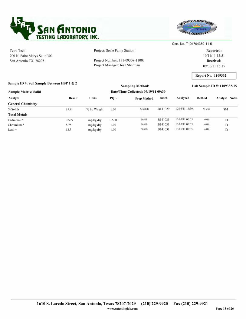
Project: Seale Pump Station
Project Number: 131-09308-11003
Project Manager: Josh Sherman
Reported:Tetra Tech
700 N. Saint Marys Suite 300 10/11/11 15:51
San Antonio TX, 78205
Report No. 1109332
Cert. No. T104704360-11-5
Received:
09/30/11 16:15
Sample ID #: Soil Sample Between HSP 1 & 2
Sample Matrix: Solid
Sampling Method:
Date/Time Collected: 09/19/11 09:30
Lab Sample ID #: 1109332-15
Analyte Result PQL Batch Analyzed MethodUnits Analyst NotesPrep Method
General Chemistry
10/04/11 14:301.00 B141029 % Calc85.9 % by Weight SM% Solids % Solids
Total Metals
10/05/11 00:050.500 B141031 60100.599 mg/kg dry IDCadmium * 3050B
10/05/11 00:051.00 B141031 60108.75 mg/kg dry IDChromium * 3050B
10/05/11 00:051.00 B141031 601012.3 mg/kg dry IDLead * 3050B
1610 S. Laredo Street, San Antonio, Texas 78207-7029 (210) 229-9920 Fax (210) 229-9921www.satestinglab.com Page 15 of 26

Project: Seale Pump Station
Project Number: 131-09308-11003
Project Manager: Josh Sherman
Reported:Tetra Tech
700 N. Saint Marys Suite 300 10/11/11 15:51
San Antonio TX, 78205
Report No. 1109332
Cert. No. T104704360-11-5
Received:
09/30/11 16:15
Sample ID #: Soil Sample East of Old Pump Bldg. Midfield
Sample Matrix: Solid
Sampling Method:
Date/Time Collected: 09/19/11 09:45
Lab Sample ID #: 1109332-16
Analyte Result PQL Batch Analyzed MethodUnits Analyst NotesPrep Method
General Chemistry
10/04/11 14:301.00 B141029 % Calc87.4 % by Weight SM% Solids % Solids
Total Metals
10/05/11 00:110.500 B141031 60100.584 mg/kg dry IDCadmium * 3050B
10/05/11 00:111.00 B141031 60108.82 mg/kg dry IDChromium * 3050B
10/05/11 00:111.00 B141031 601037.6 mg/kg dry IDLead * 3050B
1610 S. Laredo Street, San Antonio, Texas 78207-7029 (210) 229-9920 Fax (210) 229-9921www.satestinglab.com Page 16 of 26

Project: Seale Pump Station
Project Number: 131-09308-11003
Project Manager: Josh Sherman
Reported:Tetra Tech
700 N. Saint Marys Suite 300 10/11/11 15:51
San Antonio TX, 78205
Report No. 1109332
Cert. No. T104704360-11-5
Received:
09/30/11 16:15
Sample ID #: Soil Sample East of Old Bldg. by Window Pane
Sample Matrix: Solid
Sampling Method:
Date/Time Collected: 09/19/11 10:00
Lab Sample ID #: 1109332-17
Analyte Result PQL Batch Analyzed MethodUnits Analyst NotesPrep Method
General Chemistry
10/04/11 14:301.00 B141029 % Calc84.0 % by Weight SM% Solids % Solids
Total Metals
10/05/11 00:170.500 B141031 60100.667 mg/kg dry IDCadmium * 3050B
10/05/11 00:171.00 B141031 601010.0 mg/kg dry IDChromium * 3050B
10/05/11 00:171.00 B141031 601029.7 mg/kg dry IDLead * 3050B
1610 S. Laredo Street, San Antonio, Texas 78207-7029 (210) 229-9920 Fax (210) 229-9921www.satestinglab.com Page 17 of 26

Project: Seale Pump Station
Project Number: 131-09308-11003
Project Manager: Josh Sherman
Reported:Tetra Tech
700 N. Saint Marys Suite 300 10/11/11 15:51
San Antonio TX, 78205
Report No. 1109332
Cert. No. T104704360-11-5
Received:
09/30/11 16:15
Sample ID #: Soil Sample Well 2 West
Sample Matrix: Solid
Sampling Method:
Date/Time Collected: 09/19/11 10:05
Lab Sample ID #: 1109332-18
Analyte Result PQL Batch Analyzed MethodUnits Analyst NotesPrep Method
General Chemistry
10/04/11 14:301.00 B141029 % Calc86.9 % by Weight SM% Solids % Solids
Total Metals
10/05/11 00:230.500 B141031 60100.683 mg/kg dry IDCadmium * 3050B
10/05/11 00:231.00 B141031 60108.35 mg/kg dry IDChromium * 3050B
10/05/11 00:231.00 B141031 60108.31 mg/kg dry IDLead * 3050B
1610 S. Laredo Street, San Antonio, Texas 78207-7029 (210) 229-9920 Fax (210) 229-9921www.satestinglab.com Page 18 of 26

Project: Seale Pump Station
Project Number: 131-09308-11003
Project Manager: Josh Sherman
Reported:Tetra Tech
700 N. Saint Marys Suite 300 10/11/11 15:51
San Antonio TX, 78205
Report No. 1109332
Cert. No. T104704360-11-5
Received:
09/30/11 16:15
Sample ID #: Soil Sample Well #3 North
Sample Matrix: Solid
Sampling Method:
Date/Time Collected: 09/19/11 10:10
Lab Sample ID #: 1109332-19
Analyte Result PQL Batch Analyzed MethodUnits Analyst NotesPrep Method
General Chemistry
10/04/11 14:301.00 B141029 % Calc83.9 % by Weight SM% Solids % Solids
Total Metals
10/05/11 00:290.500 B141031 60100.897 mg/kg dry IDCadmium * 3050B
10/05/11 00:291.00 B141031 601010.2 mg/kg dry IDChromium * 3050B
10/05/11 00:291.00 B141031 601032.5 mg/kg dry IDLead * 3050B
1610 S. Laredo Street, San Antonio, Texas 78207-7029 (210) 229-9920 Fax (210) 229-9921www.satestinglab.com Page 19 of 26

Project: Seale Pump Station
Project Number: 131-09308-11003
Project Manager: Josh Sherman
Reported:Tetra Tech
700 N. Saint Marys Suite 300 10/11/11 15:51
San Antonio TX, 78205
Report No. 1109332
Cert. No. T104704360-11-5
Received:
09/30/11 16:15
Sample ID #: Soil Sample Well #4
Sample Matrix: Solid
Sampling Method:
Date/Time Collected: 09/19/11 10:20
Lab Sample ID #: 1109332-20
Analyte Result PQL Batch Analyzed MethodUnits Analyst NotesPrep Method
General Chemistry
10/04/11 14:301.00 B141029 % Calc86.8 % by Weight SM% Solids % Solids
Total Metals
10/05/11 00:350.500 B141031 60100.550 mg/kg dry IDCadmium * 3050B
10/05/11 00:351.00 B141031 60108.42 mg/kg dry IDChromium * 3050B
10/05/11 00:351.00 B141031 60108.80 mg/kg dry IDLead * 3050B
1610 S. Laredo Street, San Antonio, Texas 78207-7029 (210) 229-9920 Fax (210) 229-9921www.satestinglab.com Page 20 of 26
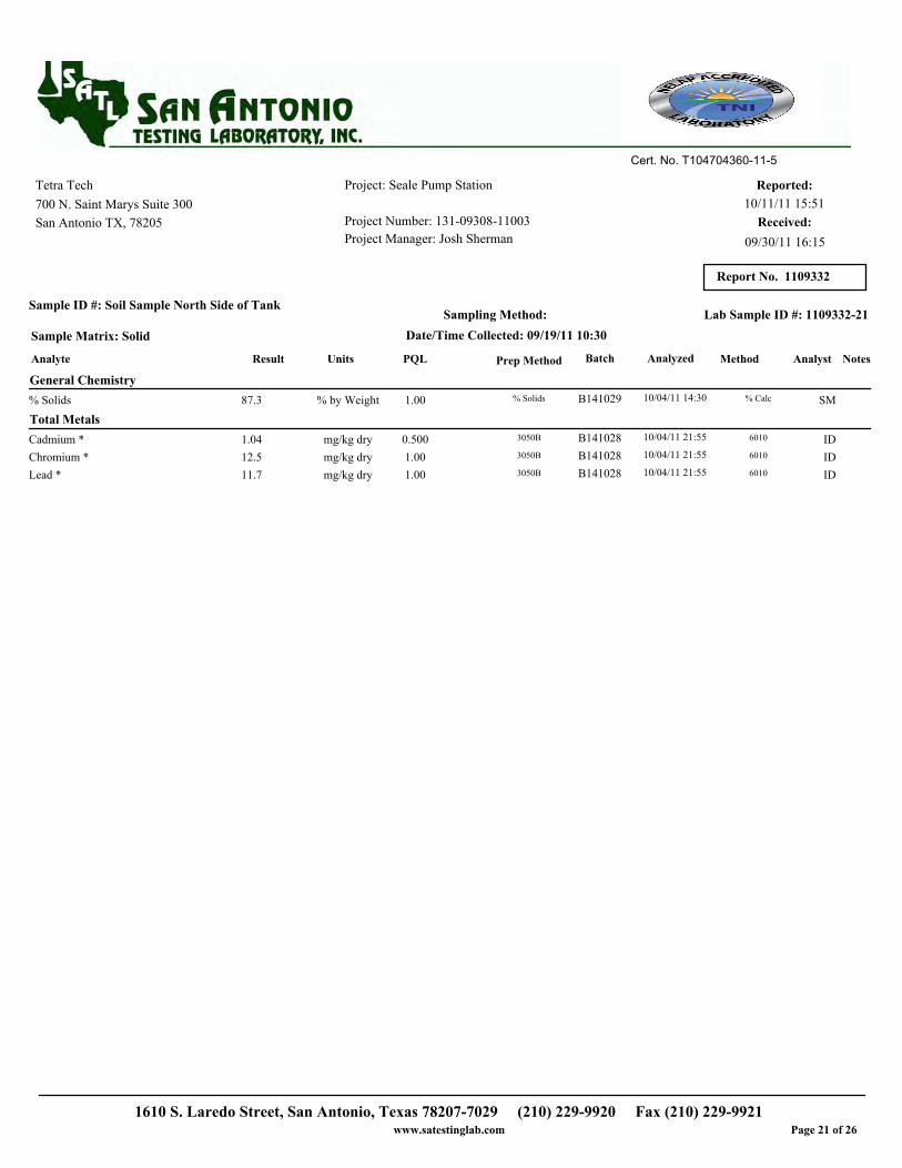
Project: Seale Pump Station
Project Number: 131-09308-11003
Project Manager: Josh Sherman
Reported:Tetra Tech
700 N. Saint Marys Suite 300 10/11/11 15:51
San Antonio TX, 78205
Report No. 1109332
Cert. No. T104704360-11-5
Received:
09/30/11 16:15
Sample ID #: Soil Sample North Side of Tank
Sample Matrix: Solid
Sampling Method:
Date/Time Collected: 09/19/11 10:30
Lab Sample ID #: 1109332-21
Analyte Result PQL Batch Analyzed MethodUnits Analyst NotesPrep Method
General Chemistry
10/04/11 14:301.00 B141029 % Calc87.3 % by Weight SM% Solids % Solids
Total Metals
10/04/11 21:550.500 B141028 60101.04 mg/kg dry IDCadmium * 3050B
10/04/11 21:551.00 B141028 601012.5 mg/kg dry IDChromium * 3050B
10/04/11 21:551.00 B141028 601011.7 mg/kg dry IDLead * 3050B
1610 S. Laredo Street, San Antonio, Texas 78207-7029 (210) 229-9920 Fax (210) 229-9921www.satestinglab.com Page 21 of 26

Project: Seale Pump Station
Project Number: 131-09308-11003
Project Manager: Josh Sherman
Reported:Tetra Tech
700 N. Saint Marys Suite 300 10/11/11 15:51
San Antonio TX, 78205
Report No. 1109332
Cert. No. T104704360-11-5
Received:
09/30/11 16:15
Sample ID #: Soil Sample West Side of Tank
Sample Matrix: Solid
Sampling Method:
Date/Time Collected: 09/19/11 10:40
Lab Sample ID #: 1109332-22
Analyte Result PQL Batch Analyzed MethodUnits Analyst NotesPrep Method
General Chemistry
10/04/11 14:301.00 B141029 % Calc89.0 % by Weight SM% Solids % Solids
Total Metals
10/04/11 22:010.500 B141028 60100.896 mg/kg dry IDCadmium * 3050B
10/04/11 22:011.00 B141028 601013.7 mg/kg dry IDChromium * 3050B
10/04/11 22:011.00 B141028 601010.8 mg/kg dry IDLead * 3050B
1610 S. Laredo Street, San Antonio, Texas 78207-7029 (210) 229-9920 Fax (210) 229-9921www.satestinglab.com Page 22 of 26

Project: Seale Pump Station
Project Number: 131-09308-11003
Project Manager: Josh Sherman
Reported:Tetra Tech
700 N. Saint Marys Suite 300 10/11/11 15:51
San Antonio TX, 78205
Report No. 1109332
Cert. No. T104704360-11-5
Received:
09/30/11 16:15
Sample ID #: Soil Sample Well #3 West
Sample Matrix: Solid
Sampling Method:
Date/Time Collected: 09/19/11 10:50
Lab Sample ID #: 1109332-23
Analyte Result PQL Batch Analyzed MethodUnits Analyst NotesPrep Method
General Chemistry
10/04/11 14:301.00 B141029 % Calc78.9 % by Weight SM% Solids % Solids
Total Metals
10/04/11 22:070.500 B141028 60100.862 mg/kg dry IDCadmium * 3050B
10/04/11 22:071.00 B141028 60108.92 mg/kg dry IDChromium * 3050B
10/04/11 22:071.00 B141028 601026.0 mg/kg dry IDLead * 3050B
1610 S. Laredo Street, San Antonio, Texas 78207-7029 (210) 229-9920 Fax (210) 229-9921www.satestinglab.com Page 23 of 26

Project: Seale Pump Station
Project Number: 131-09308-11003
Project Manager: Josh Sherman
Reported:Tetra Tech
700 N. Saint Marys Suite 300 10/11/11 15:51
San Antonio TX, 78205
Report No. 1109332
Cert. No. T104704360-11-5
Received:
09/30/11 16:15
Result Limit
Reporting
Units Level
Spike
Result
Source
%REC
%REC
Limits RPD
RPD
Limit Analyte
Total Metals - Quality Control
Batch B141028 - 3050B
Blank (B141028-BLK1) Prepared: 10/04/11 14:13 Analyzed: 10/04/11 19:20
Cadmium 0.500 mg/kg wet<0.500
Chromium 1.00 mg/kg wet<1.00
Lead 1.00 mg/kg wet<1.00
LCS (B141028-BS1) Prepared: 10/04/11 14:13 Analyzed: 10/04/11 19:26
Cadmium 0.500 99.8 80-12097mg/kg wet97.1
Chromium 1.00 99.8 80-12093mg/kg wet93.2
Lead 1.00 99.8 80-12098mg/kg wet97.3
LCS Dup (B141028-BSD1) Prepared: 10/04/11 14:13 Analyzed: 10/04/11 19:31
Cadmium 0.500 99.0 3080-12095 3mg/kg wet94.0
Chromium 1.00 99.0 3080-12090 4mg/kg wet89.5
Lead 1.00 99.0 3080-12095 3mg/kg wet94.5
Matrix Spike (B141028-MS1) Source: 1109326-13 Prepared: 10/04/11 14:13 Analyzed: 10/04/11 19:48
Cadmium 0.500 105 MSL75-12570mg/kg dry74.6 0.415
Chromium 1.00 105 MSL75-12572mg/kg dry80.7 4.90
Lead 1.00 105 MSL75-12567mg/kg dry75.0 3.95
Matrix Spike Dup (B141028-MSD1) Source: 1109326-13 Prepared: 10/04/11 14:13 Analyzed: 10/04/11 19:54
Cadmium 0.500 106 30 MSDL75-12567 4mg/kg dry71.3 0.415
Chromium 1.00 106 30 MSDL75-12570 2mg/kg dry79.1 4.90
Lead 1.00 106 30 MSDL75-12564 4mg/kg dry71.7 3.95
Batch B141031 - 3050B
Blank (B141031-BLK1) Prepared: 10/04/11 14:46 Analyzed: 10/04/11 22:45
Cadmium 0.500 mg/kg wet<0.500
Chromium 1.00 mg/kg wet<1.00
Lead 1.00 mg/kg wet<1.00
LCS (B141031-BS1) Prepared: 10/04/11 14:46 Analyzed: 10/04/11 22:51
Cadmium 0.500 100 80-12095mg/kg wet95.1
Chromium 1.00 100 80-12093mg/kg wet92.8
Lead 1.00 100 80-12096mg/kg wet95.6
LCS Dup (B141031-BSD1) Prepared: 10/04/11 14:46 Analyzed: 10/04/11 22:56
Cadmium 0.500 100 3080-12095 0.4mg/kg wet95.5
Chromium 1.00 100 3080-12092 0.8mg/kg wet92.1
Lead 1.00 100 3080-12096 0.4mg/kg wet96.0
1610 S. Laredo Street, San Antonio, Texas 78207-7029 (210) 229-9920 Fax (210) 229-9921www.satestinglab.com Page 24 of 26
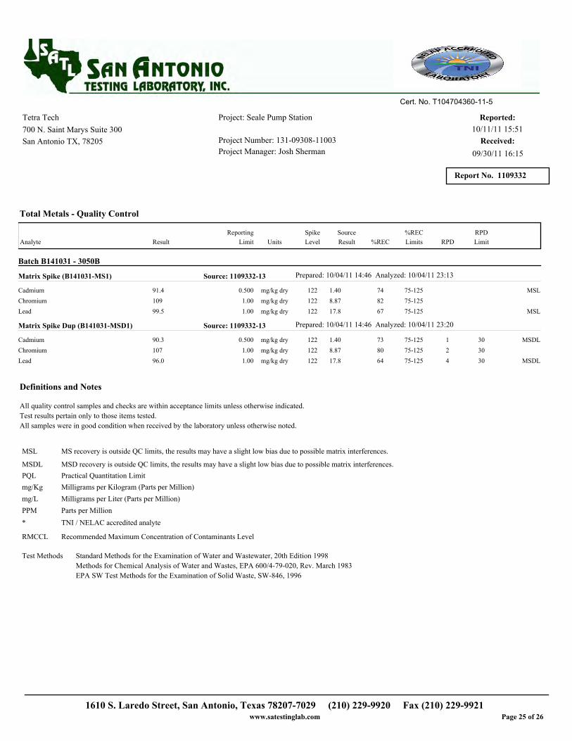
Project: Seale Pump Station
Project Number: 131-09308-11003
Project Manager: Josh Sherman
Reported:Tetra Tech
700 N. Saint Marys Suite 300 10/11/11 15:51
San Antonio TX, 78205
Report No. 1109332
Cert. No. T104704360-11-5
Received:
09/30/11 16:15
Result Limit
Reporting
Units Level
Spike
Result
Source
%REC
%REC
Limits RPD
RPD
Limit Analyte
Total Metals - Quality Control
Batch B141031 - 3050B
Matrix Spike (B141031-MS1) Source: 1109332-13 Prepared: 10/04/11 14:46 Analyzed: 10/04/11 23:13
Cadmium 0.500 122 MSL75-12574mg/kg dry91.4 1.40
Chromium 1.00 122 75-12582mg/kg dry109 8.87
Lead 1.00 122 MSL75-12567mg/kg dry99.5 17.8
Matrix Spike Dup (B141031-MSD1) Source: 1109332-13 Prepared: 10/04/11 14:46 Analyzed: 10/04/11 23:20
Cadmium 0.500 122 30 MSDL75-12573 1mg/kg dry90.3 1.40
Chromium 1.00 122 3075-12580 2mg/kg dry107 8.87
Lead 1.00 122 30 MSDL75-12564 4mg/kg dry96.0 17.8
All quality control samples and checks are within acceptance limits unless otherwise indicated.
Test results pertain only to those items tested.
All samples were in good condition when received by the laboratory unless otherwise noted.
Definitions and Notes
MSL MS recovery is outside QC limits, the results may have a slight low bias due to possible matrix interferences.
MSDL MSD recovery is outside QC limits, the results may have a slight low bias due to possible matrix interferences.
Milligrams per Kilogram (Parts per Million)mg/Kg
Practical Quantitation LimitPQL
Milligrams per Liter (Parts per Million)mg/L
Parts per MillionPPM
TNI / NELAC accredited analyte*
RMCCL Recommended Maximum Concentration of Contaminants Level
Standard Methods for the Examination of Water and Wastewater, 20th Edition 1998
Methods for Chemical Analysis of Water and Wastes, EPA 600/4-79-020, Rev. March 1983
EPA SW Test Methods for the Examination of Solid Waste, SW-846, 1996
Test Methods
1610 S. Laredo Street, San Antonio, Texas 78207-7029 (210) 229-9920 Fax (210) 229-9921www.satestinglab.com Page 25 of 26

Project: Seale Pump Station
Project Number: 131-09308-11003
Project Manager: Josh Sherman
Reported:Tetra Tech
700 N. Saint Marys Suite 300 10/11/11 15:51
San Antonio TX, 78205
Report No. 1109332
Cert. No. T104704360-11-5
Received:
09/30/11 16:15
Aimee Landon For Marcela Gracia Hawk, President For The results in this report apply to the samples analyzed in accordance with the chain of
custody document. This analytical report must be reproduced in its entirety.
Richard Hawk, General Manager
1610 S. Laredo Street, San Antonio, Texas 78207-7029 (210) 229-9920 Fax (210) 229-9921www.satestinglab.com Page 26 of 26