Embed Size (px)
Citation preview
7/14/2019 Continuum IO+Modules US A4
http://slidepdf.com/reader/full/continuum-iomodules-us-a4 1/22
Andover ContinuumTM
I/O Modl
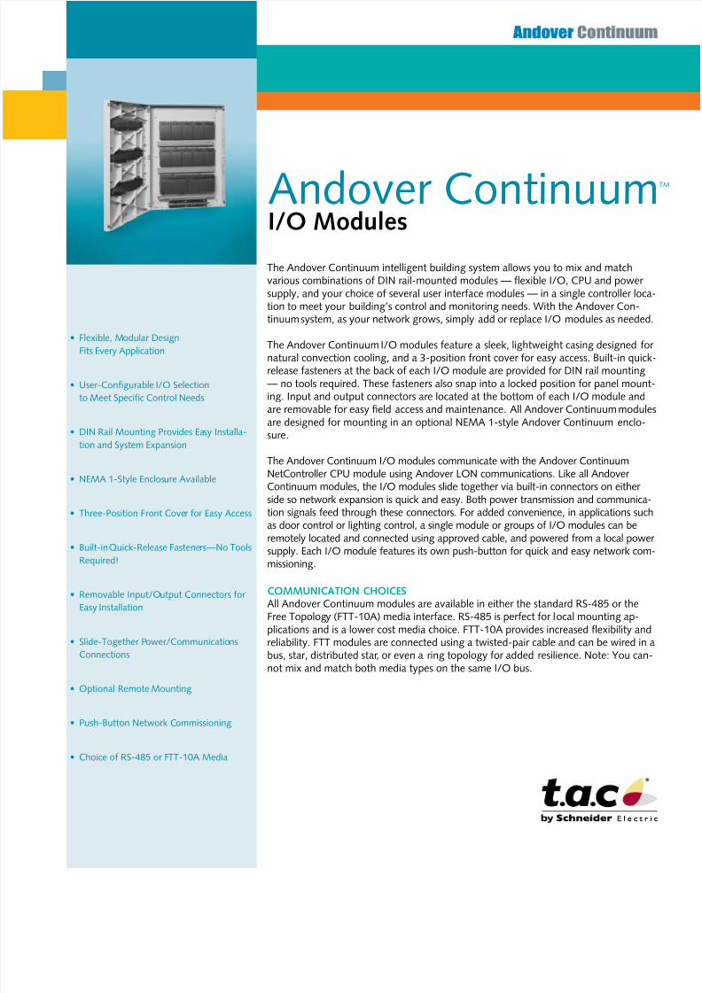
The Andover Continuum intelligent building system allows you to mix and matchvarious combinations o DIN rail-mounted modules — exible I/O, CPU and power supply, and your choice o several user interace modules — in a single controller loca-tion to meet your building’s control and monitoring needs. With the Andover Con-tinuum system, as your network grows, simply add or replace I/O modules as needed.
The Andover Continuum I/O modules eature a sleek, lightweight casing designed or natural convection cooling, and a 3-position ront cover or easy access. Built-in quick-release asteners at the back o each I/O module are provided or DIN rail mounting— no tools required. These asteners also snap into a locked position or panel mount-ing. Input and output connectors are located at the bottom o each I/O module andare removable or easy feld access and maintenance. All Andover Continuum modulesare designed or mounting in an optional NEMA 1-style Andover Continuum enclo-sure.
The Andover Continuum I/O modules communicate with the Andover ContinuumNetController CPU module using Andover LON communications. Like all Andover Continuum modules, the I/O modules slide together via built-in connectors on either side so network expansion is quick and easy. Both power transmission and communica-tion signals eed through these connectors. For added convenience, in applications such
as door control or lighting control, a single module or groups o I/O modules can beremotely located and connected using approved cable, and powered rom a local power supply. Each I/O module eatures its own push-button or quick and easy network com-missioning.
cOMMunIcatIOn chOIcesAll Andover Continuum modules are available in either the standard RS-485 or theFree Topology (FTT-10A) media interace. RS-485 is perect or local mounting ap-plications and is a lower cost media choice. FTT-10A provides increased exibility andreliability. FTT modules are connected using a twisted-pair cable and can be wired in abus, star, distributed star, or even a ring topology or added resilience. Note: You can-not mix and match both media types on the same I/O bus.
• Flexible, Modular Design
Fits Every Application
• User-Configurable I/O Selection
to Meet Speciic Control Needs
• DIN Rail Mounting Provides Easy Installa-
tion and System Expansion
• NEMA 1-Style Enclosure Available
• Three-Position Front Cover for Easy Access
• Built-in Quick-Release Fasteners—No Tools
Required!
• Removable Input/Output Connectors for
Easy Installation
• Slide-Together Power/Communications
Connections
• Optional Remote Mounting
• Push-Button Network Commissioning
• Choice of RS-485 or FTT-10A Media
7/14/2019 Continuum IO+Modules US A4
http://slidepdf.com/reader/full/continuum-iomodules-us-a4 2/22
2
MechanIcaLOrig evirom:
32–120°F (0 to 49°C), 10–95%RH(non-condensing)
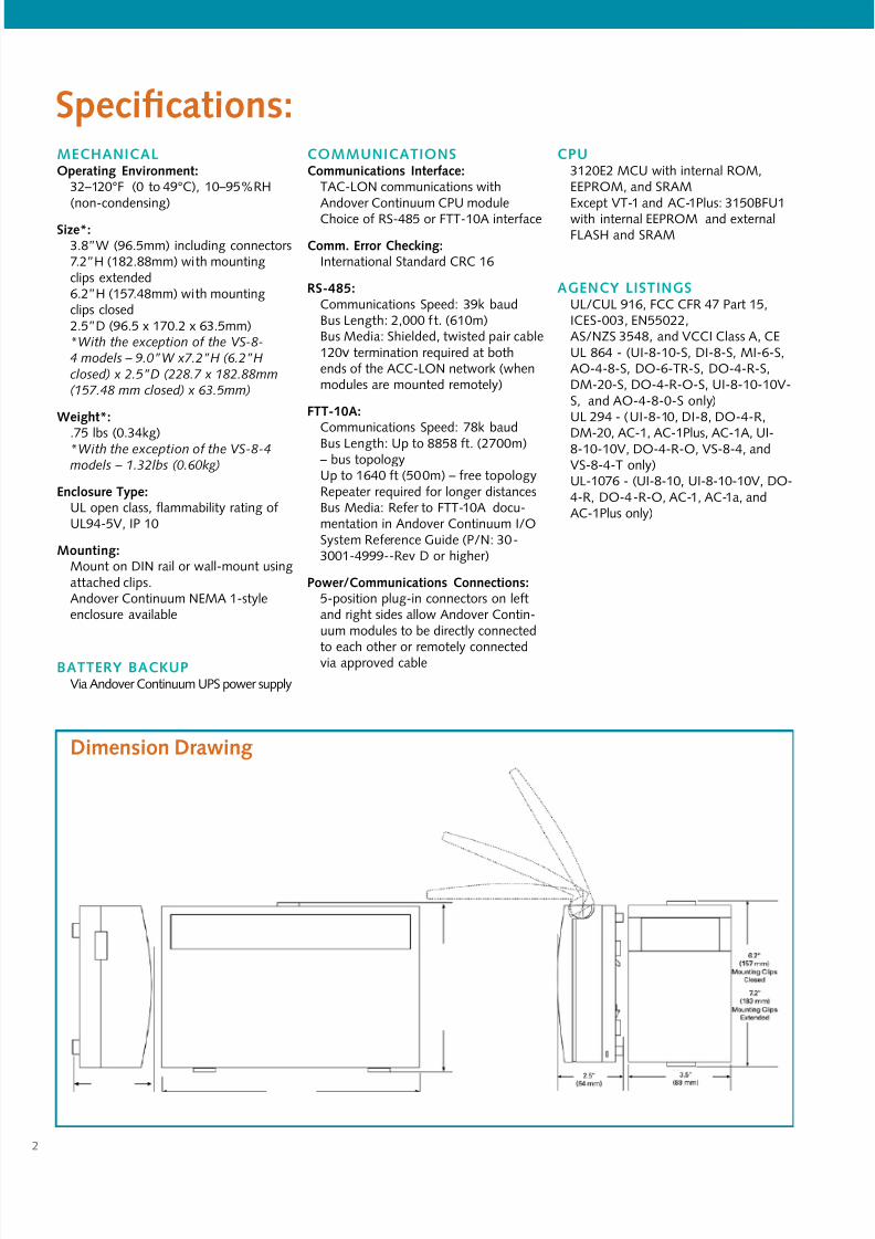
siz*:3.8”W (96.5mm) including connectors7.2”H (182.88mm) with mountingclips extended6.2”H (157.48mm) with mountingclips closed2.5”D (96.5 x 170.2 x 63.5mm)*With the exception of the VS-8-4 models – 9.0”W x7.2”H (6.2”H
closed) x 2.5”D (228.7 x 182.88mm(157.48 mm closed) x 63.5mm)
Wig*:
.75 lbs (0.34kg)*With the exception of the VS-8-4models – 1.32lbs (0.60kg)
elor ty:UL open class, ammability rating oUL94-5V, IP 10
Moig:Mount on DIN rail or wall-mount usingattached clips.Andover Continuum NEMA 1-styleenclosure available
BatteRY BackupVia Andover Continuum UPS power supply
sifio:cOMMunIcatIOnscommiio Ir:
TAC-LON communications withAndover Continuum CPU module
Choice o RS-485 or FTT-10A interace
comm. error cig:International Standard CRC 16
Rs-485:Communications Speed: 39k baudBus Length: 2,000 t. (610m)Bus Media: Shielded, twisted pair cable120v termination required at bothends o the ACC-LON network (whenmodules are mounted remotely)
Ftt-10a:
Communications Speed: 78k baudBus Length: Up to 8858 t. (2700m)– bus topologyUp to 1640 t (500m) – ree topologyRepeater required or longer distancesBus Media: Reer to FTT-10A docu-mentation in Andover Continuum I/OSystem Reerence Guide (P/N: 30-3001-4999--Rev D or higher)
powr/commiio coio:5-position plug-in connectors on letand right sides allow Andover Contin-uum modules to be directly connected
to each other or remotely connectedvia approved cable
cpu3120E2 MCU with internal ROM,EEPROM, and SRAMExcept VT-1 and AC-1Plus: 3150BFU1
with internal EEPROM and externalFLASH and SRAM
aGencY LIstInGsUL/CUL 916, FCC CFR 47 Part 15,ICES-003, EN55022,AS/NZS 3548, and VCCI Class A, CEUL 864 - (UI-8-10-S, DI-8-S, MI-6-S,AO-4-8-S, DO-6-TR-S, DO-4-R-S,DM-20-S, DO-4-R-O-S, UI-8-10-10V-S, and AO-4-8-0-S only)UL 294 - (UI-8-10, DI-8, DO-4-R,
DM-20, AC-1, AC-1Plus, AC-1A, UI-8-10-10V, DO-4-R-O, VS-8-4, andVS-8-4-T only)UL-1076 - (UI-8-10, UI-8-10-10V, DO-4-R, DO-4-R-O, AC-1, AC-1a, andAC-1Plus only)
Dimio Drwig

7/14/2019 Continuum IO+Modules US A4
http://slidepdf.com/reader/full/continuum-iomodules-us-a4 3/22
3
The UI-8-10, Andover Continuum’s universal input module, provides 8 universal inputs,sotware confgurable as voltage, thermistor, digital, or counter point types. Each pointcan also be confgured as a supervised input or security monitoring, providing separateindication o alarm and trouble conditions. This module is a perect choice or any mix otemperature, pressure, ow, status points, and similar inputs in a control system, with a0–5 volt input range and 10-bit A/D conversion.
A UI-8-10-10V model is also available or 0–10 volt applications. It provides the identicalpoint type selection, but is equipped with individual voltage divider DIP switches on each
input, allowing each to be confgured or a 0-10 volt range.
UI-8-10I/O Modl
eLectRIcaLpowr comio:
0.7 W @ 10-28VDC max.
Ovrlod proio:0.5 A resettable use with transientvoltage suppressor (TVS) and reversepolarity protection.
Inputsnmbr o I:
8 Universal inputs; 10 bit resolution
I ty:Voltage, Thermistor, Digital, Counter,and Supervised
I proio:24 V AC/DC allowed to any singleinput (40V TVS on each input– UI-8-10-10V model only)
I Imd:UI-8-10 (0–5V): 5 MW w/pullup dis-abled; 10 KW w/pullup enabledUI-8-10-10V (0–10V): 4.4 KW
I coio:Two-piece, 13-position removableterminal block
Volg:UI-8-10 (0–5V)
Range: 0–5 VResolution: 5 mVAccuracy: ±15 mV (±0.3% FSR)
UI-8-10-10V (0–10V)Range: 0–10 VResolution: 10 mVAccuracy: ±15 mV V (±0.4% FSR)
trmior:UI-8-10 (0–5V)
Type: 10 KW, Type III Thermistor Range: -30 to 230°F (-34 to 110°C)Resolution: 40 to 100°F range(4 to 38°C)Accuracy: 40 to 100°F range(4 to 38°C)
UI-8-10-10V (0–10V)Type: 10 KW, Type III Thermistor Range: -30 to 230°F (-34 to 110°C)Resolution: 0.20°F typical(0.11°C typical)Accuracy: ±1.0°F (±0.55°C)
Digil & cor:Input Type: Contact ClosureFrequency: 4 Hz (max.)Pulse Width: 125 ms ( min.) (Digitalpulse widths are based on Scan Time.)
srvid:Input Type: Single or Double Resistor Supervision, Parallel or Series Circuit
useR LeDs/sWItchess Idior LeDs:
Power Power Indicator Comm TD Indicator Status Service/Wink Indicator
p-Bo swi:Commission Reset
MODeLsuI-8-10:
8 Universal inputs; 0-5 Volt input range
uI-8-10-10V:8 Universal inputs; 0-10 Volt input range
sifio:
7/14/2019 Continuum IO+Modules US A4
http://slidepdf.com/reader/full/continuum-iomodules-us-a4 4/22
4
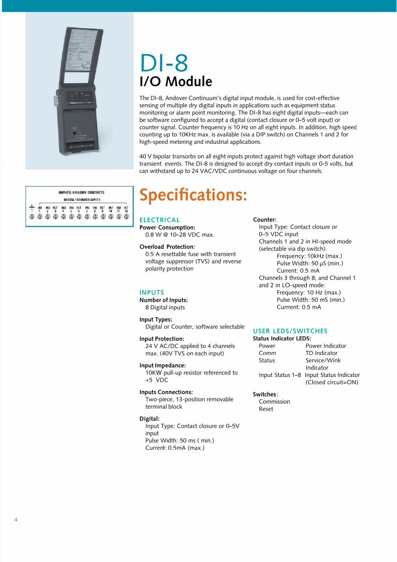
DI-8I/O ModlThe DI-8, Andover Continuum’s digital input module, is used or cost-eectivesensing o multiple dry digital inputs in applications such as equipment statusmonitoring or alarm point monitoring. The DI-8 has eight digital inputs—each canbe sotware confgured to accept a digital (contact closure or 0–5 volt input) or counter signal. Counter requency is 10 Hz on all eight inputs. In addition, high speedcounting up to 10KHz max. is available (via a DIP switch) on Channels 1 and 2 or high-speed metering and industrial applications.
40 V bipolar transorbs on all eight inputs protect against high voltage short durationtransient events. The DI-8 is designed to accept dry contact inputs or 0-5 volts, butcan withstand up to 24 VAC/VDC continuous voltage on our channels.
eLectRIcaLpowr comio:
0.8 W @ 10–28 VDC max.
Ovrlod proio:0.5 A resettable use with transientvoltage suppressor (TVS) and reversepolarity protection
Inputsnmbr o I:8 Digital inputs
I ty:Digital or Counter, sotware selectable
I proio:24 V AC/DC applied to 4 channelsmax. (40V TVS on each input)
I Imd:10KW pull-up resistor reerenced to+5 VDC
I coio:Two-piece, 13-position removableterminal block
Digil:Input Type: Contact closure or 0–5VinputPulse Width: 50 ms ( min.)Current: 0.5mA (max.)
cor:Input Type: Contact closure or 0–5 VDC inputChannels 1 and 2 in HI-speed mode(selectable via dip switch):
Frequency: 10kHz (max.)Pulse Width: 50 µS (min.)Current: 0.5 mA
Channels 3 through 8; and Channel 1and 2 in LO-speed mode:
Frequency: 10 Hz (max.)Pulse Width: 50 mS (min.)Currrent: 0.5 mA
useR LeDs/sWItchess Idior LeDs:
Power Power Indicator Comm TD Indicator Status Service/Wink
Indicator Input Status 1–8 Input Status Indicator
(Closed circuit=ON)
swi :CommissionReset
sifio:

7/14/2019 Continuum IO+Modules US A4
http://slidepdf.com/reader/full/continuum-iomodules-us-a4 5/22
5
DI-6-ACI/O ModlThe DI-6-AC, Andover Continuum’s digital AC input module, has six digital (“wet”) ACinputs or cost-eective ON-OFF status indication o an motor starters, solenoid valves,control relays, or external power supplies, and similar applications that require a quick andeasy way to detect voltage. The DI-6-AC monitors the absence or presence o AC or DCvoltage levels directly, with no interposing relays needed. The DI-6-AC can monitor volt-ages rom 24–120V.
A DI-6-AC-HV model is also available or sensing higher voltages—120–240V. Bothmodels can also accept DC voltages. All inputs are optically coupled with 2500V isolation
on each input or noise-ree operation.
sifio:eLectRIcaLpowr comio:
0.7 W @ 24 VDC (max).; when pro-vided by Andover Continuum power supply module
Ovrlod proio:0.5 A re-settable use with transientvoltage suppressor (TVS) and reversepolarity protection
Inputsnmbr o I:
6 Digital AC or DC voltage inputsI proio:2500 V isolation on each input. Eachinput has a 270 V metal oxide varistor (MOV.)
I coio:Two-piece, 13-position removableterminal block
DI-6-ac
ac I:AC Input Range: 20–132 VrmsAC Input Current: 5 mA (max.)
ac Volg “On” trold: 16 Vrms(Above this voltage is considered “ON”)
ac Volg “OFF” trold: 8 Vrms(Below this voltage is considered “OFF”)
I Ri (±5%): 30KW
Mimm tr On tim: 20 ms
Mimm tr OFF tim: 60 ms
Dc I Volg Rg: 20–132 V
Dc I crr: 5 mA (max.)
Dc Volg “On” trold: 20 V
(Above this voltage is considered “ON”)Dc Volg “OFF” trold: 12 V(Below this voltage is considered “OFF”)
DI-6-ac-hV
ac I:AC Input Range: 90–250 VrmsAC Input Current: 2 mA (max.)
ac Volg “On” trold: 75 Vrms(Above this voltage is considered “ON”)
ac Volg “OFF” trold: 30 Vrms(Below this voltage is considered “OFF”)
I Ri (±5%): 200KW
Mimm tr On tim: 20 ms
Mimm tr OFF tim: 60 ms
Dc I Volg Rg: 90–250 V
Dc I crr: 2 ma (m.)
Dc Volg “On” trold: 90 V(Above this voltage is considered “ON”)
Dc Volg “OFF” trold: 45 V(Below this voltage is considered “OFF”)
useR LeDs/sWItchess Idior LeDs:
Power Power Indicator Comm TD Indicator
Status Service/WinkIndicator
Input Status 1–:6 Input Status Indicator (Above voltagethreshold = ON)
swi:CommissionReset
MODeLsDI-6-ac:
6 Digital AC Inputs, 24–120 V inputsignal
DI-6-ac-hV:6 Digital AC Inputs, 120–240 V inputsignal

7/14/2019 Continuum IO+Modules US A4
http://slidepdf.com/reader/full/continuum-iomodules-us-a4 6/22
6
MI-6I/O ModlThe MI-6, Andover Continuum’s milliamp input module, allows or a directconnection o a 2-wire 0–20mA or 4–20mA sensor to any o the module’s six inputs.The need or an external resistor and an external power supply is eliminated. TheMI-6 module is a perect match or temperature transmitters, humidity and pressuretransducers, gas monitors, and other industry-standard sensors with either a 0–20mAor 4–20mA output. The six inputs on the MI-6 module have a 0-20mA range and 10
bit A/D conversion.
eLectRIcaLpowr comio:
3.8 W @ 24 VDC max.(Including up to 20mA sensor power or each input)
Ovrlod proio:0.5 A resettable use with transientvoltage suppressor (TVS) and reversepolarity protection
Inputsnmbr o I:
6 Milliamp inputs
I Rg:0–20 mA
Rolio:20 µA
ary:±80 µA (max.)
Dri:±50ppm/DegC (max.)
I Ri:
249W, 0.1%
Mimm I crr:±30 mA
Volg sly o sor:19–26 VDC
I proio:Each input: A transient voltagesuppressor (TVS) and a resettable use.Sensor voltage output: TVS andresettable use
I coio:Two-piece, 13-position removableterminal block
useR LeDs/sWItchess Idior LeDs:
Power Power Indicator Comm TD Indicator Status Service/Wink Indicator
swi:CommissionReset
sifio:
7/14/2019 Continuum IO+Modules US A4
http://slidepdf.com/reader/full/continuum-iomodules-us-a4 7/22
7
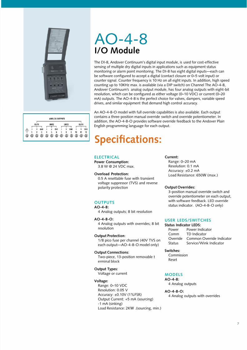
AO-4-8I/O ModlThe DI-8, Andover Continuum’s digital input module, is used or cost-eectivesensing o multiple dry digital inputs in applications such as equipment statusmonitoring or alarm point monitoring. The DI-8 has eight digital inputs—each canbe sotware confgured to accept a digital (contact closure or 0–5 volt input) or counter signal. Counter requency is 10 Hz on all eight inputs. In addition, high speedcounting up to 10KHz max. is available (via a DIP switch) on Channel The AO-4-8,Andover Continuum’s analog output module, has our analog outputs with eight-bitresolution, which can be confgured as either voltage (0–10 VDC) or current (0–20mA) outputs. The AO-4-8 is the perect choice or valves, dampers, variable speeddrives, and similar equipment that demand high control accuracy.
An AO-4-8-O model with ull override capabilities is also available. Each outputcontains a three-position manual override switch and override potentiometer. In
addition, the AO-4-8-O provides sotware override eedback to the Andover PlainEnglish programming language or each output.
eLectRIcaLpowr comio:
3.8 W @ 24 VDC max.
Ovrlod proio:0.5 A resettable use with transient
voltage suppressor (TVS) and reversepolarity protection
OutputsaO-4-8:
4 Analog outputs; 8 bit resolution
aO-4-8-O:4 Analog outputs with overrides; 8 bitresolution
O proio:1/8 pico use per channel (40V TVS on
each output—AO-4-8-O model only)
O coio:Two-piece, 13-position removable terminal block
O ty:Voltage or current
Volg:Range: 0–10 VDCResolution: 0.05 VAccuracy: ±0.10V (1%FSR)Output Current: +5 mA (sourcing)-1 mA (sinking)Load Resistance: 2KW .(sourcing, min.)
crr:Range: 0–20 mAResolution: 0.1 mAAccuracy: ±0.2 mALoad Resistance: 650W (max.)
O Ovrrid:3-position manual override switch andoverride potentiometer on each output,with sotware eedback. LED overridestatus indicator. (AO-4-8-O only)
useR LeDs/sWItchess Idior LeDs:
Power Power Indicator Comm TD Indicator Override Common Override Indicator Status Service/Wink Indicator
swi:CommissionReset
MODeLsaO-4-8:
4 Analog outputs
aO-4-8-O:4 Analog outputs with overrides
sifio:
7/14/2019 Continuum IO+Modules US A4
http://slidepdf.com/reader/full/continuum-iomodules-us-a4 8/22
8
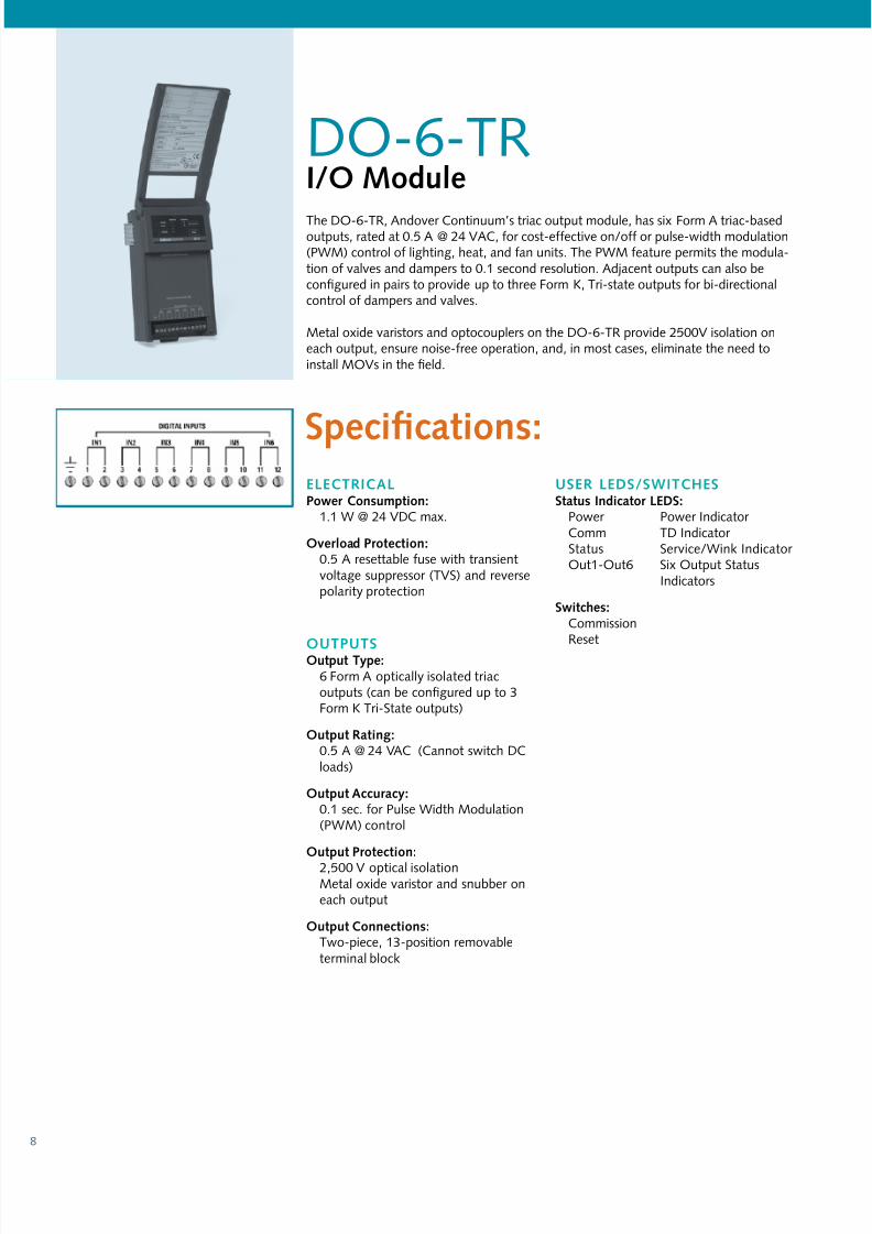
DO-6-TRI/O ModlThe DO-6-TR, Andover Continuum’s triac output module, has six Form A triac-basedoutputs, rated at 0.5 A @ 24 VAC, or cost-eective on/o or pulse-width modulation(PWM) control o lighting, heat, and an units. The PWM eature permits the modula-tion o valves and dampers to 0.1 second resolution. Adjacent outputs can also beconfgured in pairs to provide up to three Form K, Tri-state outputs or bi-directionalcontrol o dampers and valves.
Metal oxide varistors and optocouplers on the DO-6-TR provide 2500V isolation oneach output, ensure noise-ree operation, and, in most cases, eliminate the need toinstall MOVs in the feld.
eLectRIcaLpowr comio:
1.1 W @ 24 VDC max.
Ovrlod proio:0.5 A resettable use with transientvoltage suppressor (TVS) and reversepolarity protection
OutputsO ty:6 Form A optically isolated triacoutputs (can be confgured up to 3Form K Tri-State outputs)
O Rig:0.5 A @ 24 VAC (Cannot switch DCloads)
O ary:0.1 sec. or Pulse Width Modulation(PWM) control
O proio:
2,500 V optical isolationMetal oxide varistor and snubber oneach output
O coio:Two-piece, 13-position removableterminal block
useR LeDs/sWItchess Idior LeDs:
Power Power Indicator Comm TD Indicator Status Service/Wink Indicator Out1-Out6 Six Output Status
Indicators
swi:CommissionReset
sifio:
7/14/2019 Continuum IO+Modules US A4
http://slidepdf.com/reader/full/continuum-iomodules-us-a4 9/22
9
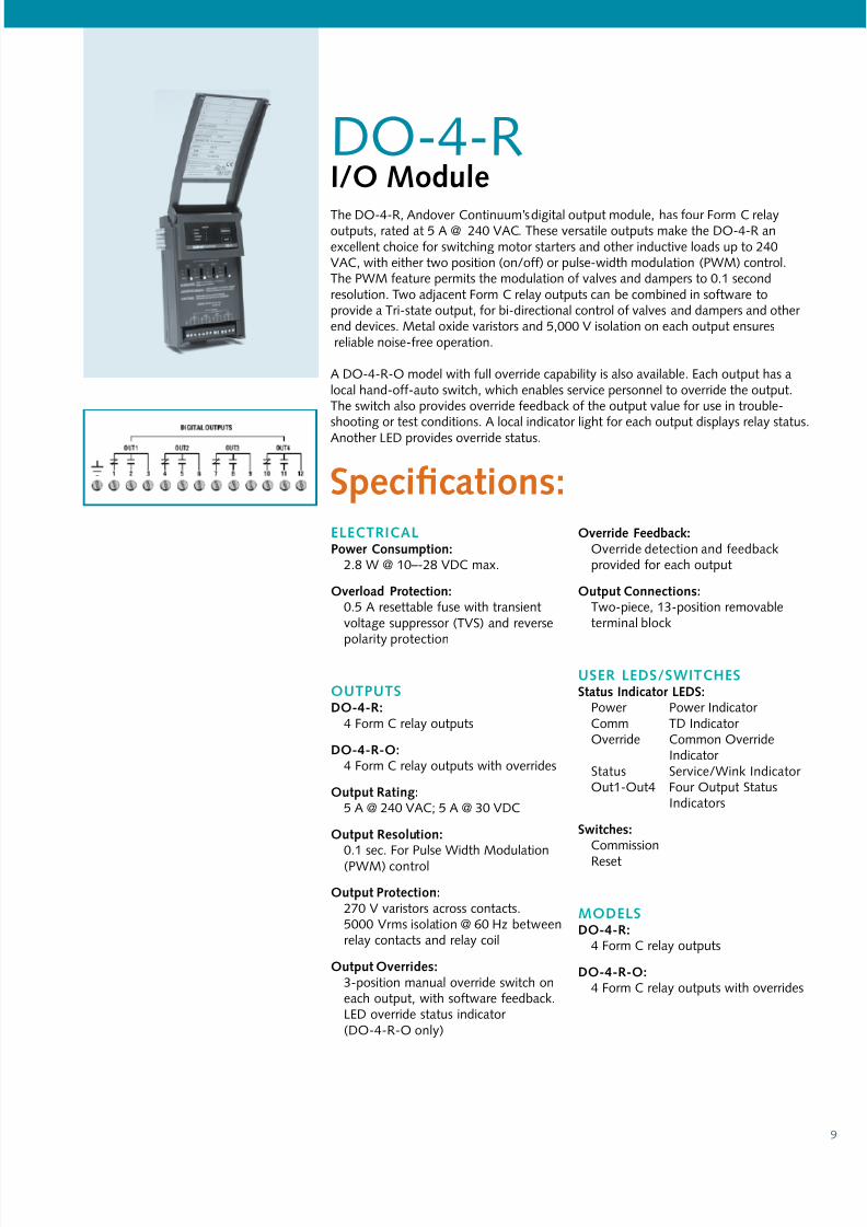
DO-4-RI/O ModlThe DO-4-R, Andover Continuum’s digital output module, has our Form C relayoutputs, rated at 5 A @ 240 VAC. These versatile outputs make the DO-4-R anexcellent choice or switching motor starters and other inductive loads up to 240VAC, with either two position (on/o) or pulse-width modulation (PWM) control.The PWM eature permits the modulation o valves and dampers to 0.1 secondresolution. Two adjacent Form C relay outputs can be combined in sotware toprovide a Tri-state output, or bi-directional control o valves and dampers and other end devices. Metal oxide varistors and 5,000 V isolation on each output ensuresreliable noise-ree operation.
A DO-4-R-O model with ull override capability is also available. Each output has alocal hand-o-auto switch, which enables service personnel to override the output.The switch also provides override eedback o the output value or use in trouble-shooting or test conditions. A local indicator light or each output displays relay status.Another LED provides override status.
eLectRIcaLpowr comio:
2.8 W @ 10–-28 VDC max.
Ovrlod proio:0.5 A resettable use with transientvoltage suppressor (TVS) and reverse
polarity protection
OutputsDO-4-R:
4 Form C relay outputs
DO-4-R-O:4 Form C relay outputs with overrides
O Rig:5 A @ 240 VAC; 5 A @ 30 VDC
O Rolio:0.1 sec. For Pulse Width Modulation(PWM) control
O proio:270 V varistors across contacts.5000 Vrms isolation @ 60 Hz betweenrelay contacts and relay coil
O Ovrrid:3-position manual override switch oneach output, with sotware eedback.LED override status indicator (DO-4-R-O only)
Ovrrid Fdb:Override detection and eedbackprovided or each output
O coio:Two-piece, 13-position removableterminal block
useR LeDs/sWItchess Idior LeDs:
Power Power Indicator Comm TD Indicator Override Common Override
Indicator Status Service/Wink Indicator Out1-Out4 Four Output Status
Indicators
swi:Commission
Reset
MODeLsDO-4-R:
4 Form C relay outputs
DO-4-R-O:4 Form C relay outputs with overrides
sifio:

7/14/2019 Continuum IO+Modules US A4
http://slidepdf.com/reader/full/continuum-iomodules-us-a4 10/22
10
DM-20I/O ModlThe DM-20, Andover Continuum’s Digital Input and Output module, provides highdensity, versatile I/O or many control applications.The DM-20 can control anycombination o 20 inputs and outputs. When coupled with the optional DIO-20 Expansion Board, the DM-20 allows youto mix and match up to 20* digital inputs and outputs using standard o-the-sheldigital I/O blocks to meet a wide range o applications, including ON-OFF or pulse-width modulation (PWM) control o equipment and or switching inductive loads upto 240VAC. The DM-20 provides 24 VDC power to the DIO-20 via a three-positioncable assembly.
* Actual number o modules depends on the mix o inputs/outputs used. See Andover Continuum I/O System Reerence Manual (Rev D or higher) or more inormation.
eLectRIcaLpowr comio:
0.5 W @ 24VDC max.Up to 9 W @ 24 VDC when the DIO-20 is powered rom the DM-20
erl powr coor:Three-position removable connector
Ovrlod proio:
0.5 A resettable use with transientvoltage suppressor (TVS) and reversepolarity protection or both DM-20power and DIO-20 power
LeD powr sly:Customer-provided external 5 V power supply when using the DM-20 to driveLEDs
Inputs/Outputs20 ol oi; r-lbl l-by-l i or o
w/o DIO-20
I ty: Digital0–5 VDC
pl Wid: 125 ms ( min.)(Digital pulse widths arebased on Scan Time.)
crr: 10µAO ty: Digital
Open- collector transistor with series 330 ohm 1/8
W resistor; 15 mA (max.)
@ 5 V DC
w/DIO-20
I ty: 24 VDC logic voltage(DIO-20). Input ratingdepends on inputmodule(s) selected
pl Wid: 125 ms ( min.)(Digital pulse widths arebased on Scan Time.)
crr: N/A
O ty: 5 VDC logic voltage.Output range depends onoutput module selected
O Rolio:0.1 sec. For Pulse Width Modulation(PWM) control
O proio:Transient voltage suppressor (TVS)and current limiting resistor on eachchannel
I/O coio:
One emale 25-pin D-subminiatureconnector
useR LeDs/sWItchess Idior LeDs:
Power Power Indicator Comm TD Indicator Status Service/Wink Indicator
swi:CommissionReset
sifio:
7/14/2019 Continuum IO+Modules US A4
http://slidepdf.com/reader/full/continuum-iomodules-us-a4 11/22
11
The AC-1 Familyo Access ControlModulesTAC® oers three access control modules to meet the demands o dierent accessrequirements:
ac-1:Use the AC-1 when powering modules rom a Andover Continuum power supply.
(AC-1 has a 24VDC power input only. ) The AC-1 supports Wiegand/Prox cards and 5V/12 V reader power (switch-selectable).
ac-1a:Use the AC-1A i you are powering modules rom a local 12VDC power supply. TheAC-1A oers an extended 10-28VDC power input. (Power supply can also power any12 V prox readers you may be using.) The AC-1A supports Wiegand/Prox cards, and5 V reader power only.
ac-1pLus:The enhanced version. Use the AC-1Plus when using mag stripe or Cardkey readers,ADA sequences that require extra inputs, special door unlock/door ajar times or dis-abled persons, and jobs that require reader tamper detection. The AC-1Plus oers an
extended 10-28VDC power input (power supply can also power 12 V prox readers),and supports 5 V reader power only.
7/14/2019 Continuum IO+Modules US A4
http://slidepdf.com/reader/full/continuum-iomodules-us-a4 12/22
12
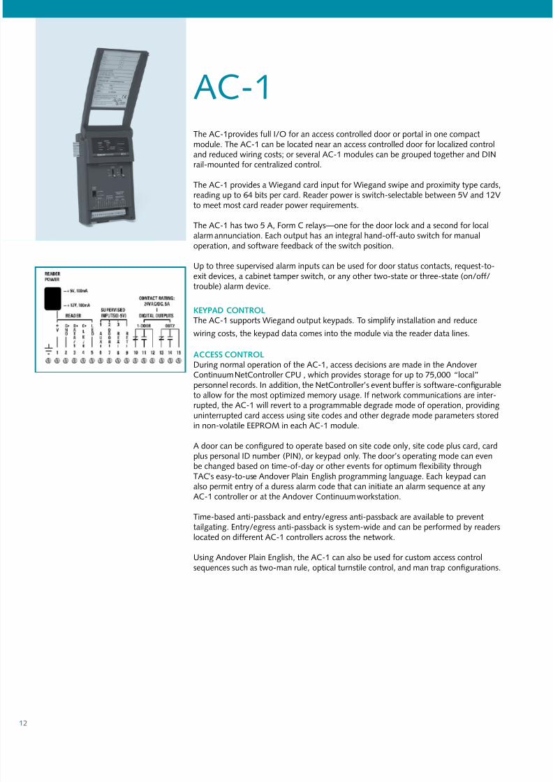
The AC-1provides ull I/O or an access controlled door or portal in one compactmodule. The AC-1 can be located near an access controlled door or localized controland reduced wiring costs; or several AC-1 modules can be grouped together and DINrail-mounted or centralized control.
The AC-1 provides a Wiegand card input or Wiegand swipe and proximity type cards,reading up to 64 bits per card. Reader power is switch-selectable between 5V and 12Vto meet most card reader power requirements.
The AC-1 has two 5 A, Form C relays—one or the door lock and a second or localalarm annunciation. Each output has an integral hand-o-auto switch or manualoperation, and sotware eedback o the switch position.
Up to three supervised alarm inputs can be used or door status contacts, request-to-
exit devices, a cabinet tamper switch, or any other two-state or three-state (on/o/trouble) alarm device.
keYpaD cOntROLThe AC-1 supports Wiegand output keypads. To simpliy installation and reduce
wiring costs, the keypad data comes into the module via the reader data lines.
access cOntROLDuring normal operation o the AC-1, access decisions are made in the Andover Continuum NetController CPU , which provides storage or up to 75,000 “local”personnel records. In addition, the NetController’s event buer is sotware-confgurableto allow or the most optimized memory usage. I network communications are inter-rupted, the AC-1 will revert to a programmable degrade mode o operation, providinguninterrupted card access using site codes and other degrade mode parameters storedin non-volatile EEPROM in each AC-1 module.
A door can be confgured to operate based on site code only, site code plus card, cardplus personal ID number (PIN), or keypad only. The door’s operating mode can evenbe changed based on time-o-day or other events or optimum exibility throughTAC’s easy-to-use Andover Plain English programming language. Each keypad canalso permit entry o a duress alarm code that can initiate an alarm sequence at anyAC-1 controller or at the Andover Continuum workstation.
Time-based anti-passback and entry/egress anti-passback are available to preventtailgating. Entry/egress anti-passback is system-wide and can be perormed by readerslocated on dierent AC-1 controllers across the network.
Using Andover Plain English, the AC-1 can also be used or custom access controlsequences such as two-man rule, optical turnstile control, and man trap confgurations.
AC-1
7/14/2019 Continuum IO+Modules US A4
http://slidepdf.com/reader/full/continuum-iomodules-us-a4 13/22
13
sifio:ac-1
eLectRIcaLpowr comio:2.6 W plus reader power consumptionat 24VDC max.
Ovrlod proio:0.5 A resettable use with transientvoltage suppressor (TVS) and reversepolarity protection
Inputs/OutputsI
crd Rdr:1
crd Rdr ty:Supports Wiegand swipe andproximity readers
Mimm nmbr o bi/crd:64
crd Rdr powr:5 VDC or 12 VDC (switch selectable)
Switch Setting: +5 VOutput Voltage : +5.20 V ±0.05 VOutput Current: 120 mA (max.)
Switch Setting: +12 VOutput Voltage : +12.0 V ±5%Output Current: 180 mA (max.)
Di, crd Rdr o ac-1:500 t. max. using 18-ga. wire200 t. max. using 22-ga. wire
alrm I:Up to 3 supervised inputs. Single or double resistor supervision, series or parallel
I proio:Transient voltage suppressor (TVS) oneach input
O
Door O:2 Form C relays
O Rig:5 A @ 24 V AC/DC
O proio:5,000 V isolation270 V metal oxide varistors (MOVs) oneach output
Ovrrid:3-position manual override switchon each output or manual control orelay. LED override status indicator
Ovrrid Fdb:
Override detection and sotware eed-back provided or each output
Rdr LeD O:Open collector; up to 50 mA
I/O coio:Two-piece, 16-position removableterminal block
useR LeDs/sWItchess Idior LeDs:Power Power Indicator Comm TD Indicator Override Common
OverrideIndicator
Status Service/WinkIndicator
Out1 - Out2 Two OutputStatus Indicators
+5 V Reader Power 5 V Reader Power Indicator
+12 V Reader Power 12 V Reader
Power Indicator
swi:CommissionReset

7/14/2019 Continuum IO+Modules US A4
http://slidepdf.com/reader/full/continuum-iomodules-us-a4 14/22
14
AC-1AI/O ModlThe AC-1A provides ull I/O or an access controlled door or portal in one compactmodule. The AC-1A can be located near an access controlled door or localizedcontrol and reduced wiring costs; or several AC-1A modules can be grouped together and DIN rail-mounted or centralized control.
The AC-1A provides a Wiegand card input or Wiegand swipe and proximity typecards, reading up to 64 bits per card. Reader power is 50 mA at 5V. The module itselcan be powered by a voltage source that can range rom 10-28 VDC.
The AC-1A has two 5 A, Form C relays — one or the door lock and a second or local alarm annunciation. Each output has an integral hand-o-auto switch or manualoperation, and sotware eedback o the switch position.
Up to three supervised alarm inputs can be used or door status contacts, request-to-exit devices, a cabinet tamper switch, or any other two-state or three-state (on/o/trouble) alarm device.
keYpaD cOntROLThe AC-1A supports Wiegand output keypads. To simpliy installation and reducewiring costs, a combination Wiegand output reader/keypad may be used. In this case,the keypad data comes into the module via the reader data lines. In addition,the AC-1A allows separate wiring o both a Wiegand output keypad and reader.
access cOntROLDuring normal operation o the AC-1A, access decisions are made in the Andover Continuum NetController CPU , which provides storage or up to 75,000 “local”personnel records. In addition, the NetController’s event buer is sotware-confgurableto allow or the most optimized memory usage. I network communications areinterrupted, the AC-1A will revert to a programmable degrade mode o operation,providing uninterrupted card access using site codes and other degrade modeparameters stored in non-volatile EEPROM in each AC-1A module.
A door can be confgured to operate based on site code only, site code plus card, cardplus personal ID number (PIN), or keypad only. The door’s operating mode can evenbe changed based on time-o-day or other events or optimum exibility throughTAC’s easy-to-use Andover Plain EnglishTM programming language. Each keypad canalso permit entry o a duress alarm code that can initiate an alarm sequence at anyAC-1A controller or at the Andover Continuum workstation.
Time-based anti-passback and entry/egress anti-passback are available to prevent
tailgating. Entry/egress anti-passback is system-wide and can be perormed by readerslocated on dierent AC-1A controllers across the network.
Using Andover Plain English, the AC-1A can also be used or custom access controlsequences such as two-man rule, optical turnstile control, and man trap confgurations.

7/14/2019 Continuum IO+Modules US A4
http://slidepdf.com/reader/full/continuum-iomodules-us-a4 15/22
15
eLectRIcaLpowr comio:
2.0 W at 10-28VDC plus reader power consumption
Ovrlod proio:0.5 A resettable use with transientvoltage suppressor (TVS) and reversepolarity protection
Inputs/OutputsI
crd Rdr:1
crd Rdr ty:Supports Wiegand swipe andproximity readers
Mimm nmbr o bi/crd:64
crd Rdr powr:5 VDC, ± 3%, 50 mA, Current Limited
Di, crd Rdr o ac-1a:
500 t. max. using 18-ga. wire200 t. max. using 22-ga. wire
alrm I:Up to 3 supervised inputs. Single or double resistor supervision, series or parallel
I proio:Transient voltage suppressor (TVS) oneach input
sifio:ac-1a
O
Door O:2 Form C relays
O Rig:5 A @ 24 V AC/DC
O proio:5,000 V isolation270 V metal oxide varistors (MOVs)on each output
Ovrrid:
3-position manual override switchon each output or manual control orelay. LED override status indicator
Ovrrid Fdb:Override detection and sotwareeedback provided or each output.
Rdr LeD O:Open collector; up to 100 mA
I/O coio:Two-piece, 18-position removableterminal block
useR LeDs/sWItchess Idior LeDs:
Power Power Indicator Comm TD Indicator Override Common Override
Indicator Status Service/Wink
Indicator Out1 - Out2 Two Output Status
Indicators+5 V Reader Power 5 V Reader Power
Indicator
swi :CommissionReset
7/14/2019 Continuum IO+Modules US A4
http://slidepdf.com/reader/full/continuum-iomodules-us-a4 16/22
16
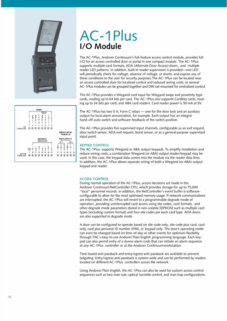
AC-1PlusI/O ModlThe AC-1Plus, Andover Continuum’s ull-eature access control module, provides ullI/O or an access controlled door or portal in one compact module. The AC-1Plussupports multiple card ormats, ADA (Alternate Door Access) doors, and multiplereader LED patterns. In addition, built-in reader supervision is provided—one LEDwill periodically check or voltage, absence o voltage, or shorts, and expose any othese conditions to the user or security purposes.The AC-1Plus can be located near an access controlled door or localized control and reduced wiring costs; or severalAC-1Plus modules can be grouped together and DIN rail-mounted or centralized control.
The AC-1Plus provides a Wiegand card input or Wiegand swipe and proximity typecards, reading up to 64 bits per card. The AC-1Plus also supports CardKey cards, read-ing up to 34 bits per card, and ABA card readers. Card reader power is 50 mA at 5V.
The AC-1Plus has two 5 A, Form C relays — one or the door lock and an auxiliaryoutput or local alarm annunciation, or example. Each output has an integralhand-o-auto switch and sotware eedback o the switch position.
The AC-1Plus provides fve supervised input channels, confgurable as an exit request,door switch sensor, ADA exit request, bond sensor, or as a general purpose supervisedinput point.
keYpaD cOntROLThe AC-1Plus supports Wiegand or ABA output keypads. To simpliy installation andreduce wiring costs, a combination Wiegand (or ABA) output reader/keypad may beused. In this case, the keypad data comes into the module via the reader data lines.In addition, the AC-1Plus allows separate wiring o both a Wiegand (or ABA) outputkeypad and reader.
access cOntROLDuring normal operation o the AC-1Plus, access decisions are made in theAndover Continuum NetController CPU, which provides storage or up to 75,000“local” personnel records. In addition, the NetController’s event buer is sotware-confgurable to allow or the most optimized memory usage. I network communicationsare interrupted, the AC-1Plus will revert to a programmable degrade mode ooperation, providing uninterrupted card access using site codes, card ormats, andother degrade mode parameters stored in non-volatile EEPROM such as multiple cardtypes (including custom ormat) and our site codes per each card type. ADA doorsare also supported in degrade mode.
A door can be confgured to operate based on site code only, site code plus card, cardonly, card plus personal ID number (PIN), or keypad only. The door’s operating modecan even be changed based on time-o-day or other events or optimum exibilitythrough TAC’s easy-to-use Andover Plain English programming language. Each key-pad can also permit entry o a duress alarm code that can initiate an alarm sequenceat any AC-1Plus controller or at the Andover Continuum workstation.
Time-based anti-passback and entry/egress anti-passback are available to preventtailgating. Entry/egress anti-passback is system-wide and can be perormed by readerslocated on dierent AC-1Plus controllers across the network.
Using Andover Plain English, the AC-1Plus can also be used or custom access controlsequences such as two-man rule, optical turnstile control, and man trap confgurations.
7/14/2019 Continuum IO+Modules US A4
http://slidepdf.com/reader/full/continuum-iomodules-us-a4 17/22
17
eLectRIcaLpowr comio:
2.2 W at 10-28VDC plus reader power consumption
Ovrlod proio:0.5 A resettable use with transientvoltage suppressor (TVS) and reversepolarity protection
Inputs/OutputsI
crd Rdr:1
crd Rdr ty:Supports Wiegand, Proximity, CardKey,and ABA readers
Mimm nmbr o bi/crd:64 or Wiegand and Proximity; 34 or CardKey
crd Rdr powr:
5 VDC, ± 3%, 50 mA, Current Limited
Di, crd Rdr o ac-1pl:500 t. max. using 18-ga. wire200 t. max. using 22-ga. wire
alrm I:5 supervised inputs. Single or doubleresistor supervision, series or parallel
I proio:Transient voltage suppressor (TVS) oneach input
sifio:ac-1Plus
O
Door O:2 Form C relays
O Rig:5 A @ 24 V AC/DC
O proio:5,000 V isolation270 V metal oxide varistors (MOVs)on each output
Ovrrid:3-position manual override switchon each output. LED overridestatus indicator
Ovrrid Fdb:Override detection and sotwareeedback provided or each output
Rdr LeD O:2 open collector; up to 100 mA.Choice o 3 LED patterns
I/O coio:Removable terminal blocks:(2) 8-position; (1) 6-position
useR LeDs/sWItchess Idior LeDs:
Power Power Indicator Comm TD Indicator Override Common Override
Indicator Status Service/Wink
Indicator Out1 - Out2 Two Output Status
Indicators+5 V Reader Power 5 V Reader Power
Indicator
swi :
CommissionReset

7/14/2019 Continuum IO+Modules US A4
http://slidepdf.com/reader/full/continuum-iomodules-us-a4 18/22
18
LO-2I/O Modl
The LO-2, Andover Continuum’s lighting control module, can control 2 high voltagelighting circuits, using externally mounted GE RR7 or RR9 lighting relays, rated or 20 A @ 277 VAC (347 VAC option or Canada). These relays are connected to theLO-2 via two three oot, 5-conductor wires provided. The RR9 relay provides statuseedback o the relay position, using a built-in pilot contact. The RR7 relay providescontrol o the circuit with no eedback. An on-board status LED or each output isprovided when RR9 relays are used, as well as pilot light voltage or wall switches thathave status indication. External 28 VAC is required to power the GE relays. This sametransormer can power the LO-2 when the module is located remotely.
An LO-2-O model, with on-board momentary override toggle switches, is also available.
exteRnaL OVeRRIDe capaBILItIesTwo Class II low voltage manual override inputs, one or each relay output, areprovided or override capabilities. These inputs directly control the lighting relays,independent o any schedule or program. Wall switches, occupancy sensors, or acombination o both may be wired to these inputs.
LIGhtInG cOntROLThe LO-2 can be coupled with Andover Continuum’s programmable input modules toprovide exible lighting control strategies such as:
• Outdoor Lighting Control with a Photocell
• Daylight Control
• After-Hours Lighting Usage with Card Swipe Readers
• Adjustable Override Time with Flick Warning• Cleaning Crew Override
• Data Logging and Reporting
• Run time Analysis, including Accumulated On-Time and Percentage On-Time
• Tenant Billing Reports
• Custom Control Strategies
These programs can be easily modifed to ft the exact needs o your project.
7/14/2019 Continuum IO+Modules US A4
http://slidepdf.com/reader/full/continuum-iomodules-us-a4 19/22
19
eLectRIcaLpowr comio:
0.4 W @ 24 VDC max. Consumes noDC power when external AC power ispresent
erl ac powr:28 VAC powers both module andlighting relays; can also power theLO-2 module when mounted remotely
erl trormr:40 VA transormer provides power or up to 5 LO-2 modules (10 GE relaysand associated devices)
Ovrlod proio:DC: 0.5 A resettable use withtransient voltage suppressor (TVS) andreverse polarity protection. AC: 0.5 Aresettable use with MOV
Inputs/OutputsI:
2 Class II Low Voltage override inputs,providing direct control o lightingrelays
I proio:
Transient voltage suppressors (TVS)with reverse polarity protection
O
O ty:2 pulsed lighting control outputscompatible with externally mountedGE RR7 or RR9 relays
sifio:LO-2
O Rig(Ligig Rly):Lamp Load – 20 A Tungsten Filament
@125 VACResistive Load – 20 A ballast @ 277VAC (@347 VAC, Canada)Motor Load – 0.5 HP @ 110-125 VAC
0.5 HP @ 220-277 VAC(0.5 HP @ 347 VAC,Canada)
pilo co Rig (RR9 oly):1 A @ 24 VAC, isolated
O Fdb:RR9 relays have LED status indicationand sotware eedback or relay status
O proio:Transient voltage suppressors (TVS) onoutputs. GE relays provide isolation
Ovrrid:Momentary override toggle switches(LO-2-O model only)
ac powr/erl Ovrrid I coio:
Two-piece, 12-position removableterminal block
Ligig Rly coio:
5-position male connector acceptsstandard GE emale plug-in connector.(Two 3-oot, 5-conductor wires withemale connectors provided. Wirescolor-coded to match GE relays.)
useR LeDs/sWItchess Idior LeDs:
Power Power Indicator Comm TD Indicator Status Service/Wink Indicator Out1-Out2 Two Output Status
Indicators (RR-9 only)24 VAC External 24-30 VAC
Indicator
swi:CommissionReset
MODeLsLO-2:2 pulsed lighting control outputs
LO-2-O:2 pulsed lighting control outputs withoverrides

7/14/2019 Continuum IO+Modules US A4
http://slidepdf.com/reader/full/continuum-iomodules-us-a4 20/22
20
VS-8-4I/O ModlThe VS-8-4, Andover Continuum’s video switch module, integrates low-cost, high qualityvideo security directly into your Andover Continuum system. The VS-8-4 switches eightvideo signal inputs and our high-speed, buered outputs. Any one o the eight inputlines can be connected to any o the our outputs. Each output has a voltage gain o twoand is capable o driving 75W back-terminated lines. Up to eight surveillance camerasand our video monitors or VCRs can be connected to a single VS-8-4 module.
The VS-8-4 can be ordered with optional date/time and caption display. Captions areselectable, allowing dierent displays based on events or alarms.
Both models can be ordered to support either the PAL or NTSC standard.
sifio:eLectRIcaLpowr comio:
2 W @ 10-28VDC max.
Ovrlod proio:0.5 A resettable use with transientvoltage suppressor (TVS) and reversepolarity protection
Inputs/Outputs
I:8 Video inputs
I Imd:75W
Bdwid (-3dB):>75MHz (R
load=150W)
sigl cl crol:>-60dB@10MHz
all cl crol:>-55dB@10MHz
all cl O Iolio:>-55dB@10MHz
O:4 Video outputs
O Imd:75W
sigl:1 V peak-peak when terminated into75W
I/O coio:75W BNC connectors
I/O proio:ESD protection provided
useR LeDs/sWItchess Idior LeDs:
Power Power Indicator
Comm TD Indicator Status Service/Wink
Indicator Input Status 1-8 Input Status Indicator
(4 LEDs per input)
swi :CommissionReset
MODeLsVs-8-4:
8 Video inputs; 4 Video outputs, NTSCor PAL video inputs
Vs-8-4-tn:8 Video inputs; 4 Video outputs withdate/time- and text-stamping or NTSC video inputs
Vs-8-4-tp:8 Video inputs; 4 Video outputs withdate/time- and text-stamping or PALvideo inputs
7/14/2019 Continuum IO+Modules US A4
http://slidepdf.com/reader/full/continuum-iomodules-us-a4 21/22
21
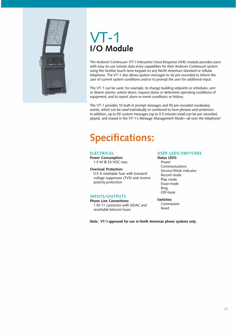
VT-1I/O Modl
The Andover Continuum VT-1 Interactive Voice Response (IVR) module provides userswith easy-to-use remote data entry capabilities or their Andover Continuum systemusing the amiliar touch-tone keypad on any North American standard or cellular telephone. The VT-1 also allows spoken messages to be pre-recorded to inorm theuser o current system conditions and/or to prompt the user or additional input.
The VT-1 can be used, or example, to change building setpoints or schedules; armor disarm alarms; unlock doors; request status or determine operating conditions oequipment; and to report alarm or event conditions or history.
The VT-1 provides 10 built-in prompt messages and 50 pre-recorded vocabularywords, which can be used individually or combined to orm phrases and sentences.In addition, up to 50 custom messages (up to 3.5 minutes total) can be pre-recorded,
played, and erased in the VT-1’s Message Management Mode—all over the telephone!
eLectRIcaLpowr comio:
1.5 W @ 24 VDC max.
Ovrlod proio:
0.5 A resettable use with transientvoltage suppressor (TVS) and reversepolarity protection
Inputs/Outputspo Li coio:
1 RJ-11 connector with SIDAC andresettable telecom uses
useR LeDs/sWItchess LeDs:
Power CommunicationsService/Wink indicator
Record modePlay modeErase modeRingO-hook
swi:CommissionReset
sifio:
no: Vt-1 rovd or i nor amri o ym oly.

7/14/2019 Continuum IO+Modules US A4
http://slidepdf.com/reader/full/continuum-iomodules-us-a4 22/22
Copyright © 2006, TAC®
All brand names, trademarks and registered trademarks arethe property o their respective owners. Inormation containedwithin this document is subject to change without notice.All rights reserved.
SDS-C-IOMODULES-US06/06