Embed Size (px)
Citation preview

Continuously Rotating Energy Harvester with Maximum Power
Point Tracking
Tzern T. Toh, Paul D. Mitcheson, Andrew S. Holmes and Eric M.Yeatman
Department of Electrical and Electronic Engineering, Imperial College London, UK.
E-mail: [email protected] and [email protected]
Abstract
In this paper, we analyse and demonstrate an energy harvesting generator powered by continuous rotation, using
gravitational torque to enable single point attachment. The electro-mechanical behaviour of the generator is
presented, alongside experimental results from an implementation based on a conventional DC motor. The off-axis
performance is also modelled. The design and experimental results for an adaptive power processing circuit are
also presented, as the first demonstration of maximum power point tracking for a motion energy harvester.
Keywords: Energy scavenging, machine monitoring, power convertor
1. Introduction
Energy harvesting from moving structures has been
a topic of much research, particularly for applications in
powering wireless sensors [1]. Most motion energy
harvesters are inertial, drawing power from the relative
motion between an oscillating proof mass and the frame
from which it is suspended [2]. The inertia of the proof
mass provides a counter-force to that presented by the
source of motion, so that no second point of attachment
is needed – this greatly expands the possible range of
installations and applications, particularly for highly
miniature devices. While most reported devices use
linear relative motion between the mass and frame,
rotating motion is also possible [3]; in fact, rotating
mass inertial generators have been the more
commercially successful to date, being well suited to
the specific application of wristwatches [4]. By the use
of a proof mass with a centre offset from the axis of
rotation, these rotational devices can be driven by either
linear or rotating source motion. However, since the
inertial counter-force results from the acceleration of
the frame, this effect cannot be used to extract power
where the host motion is constant (whether linear or
rotational).
For body motion powered devices such as
wristwatch generators, constant rotation is in any case
not available. However, for many important
applications, including tire pressure sensing and
condition monitoring of machinery, the host structure
does undergo continuous rotation. In these cases,
previous energy harvesters have typically been driven
by the associated vibration. Here, we show that
rotational motion can be used directly to harvest power
and that conventional rotating machines can be easily
adapted to this purpose.
A generic rotating generator consists of two main
components, a stator and rotor, which are rotated with
respect to each other by some external source of
motion, and a transduction mechanism (generally
electromagnetic) which impedes this relative motion,
and by doing so converts mechanical into electrical
power. An energy harvester differs from a conventional
generator firstly in that it should normally apply a
mechanical load small enough not to substantially
impede the motion source; and secondly that it will
typically be desirable to attach the harvester to the
motion source at a single point, without the need to
anchor it to a non-moving structure. The latter
requirement creates a need for a mechanism to oppose
the source rotation.
This mechanism can be straightforwardly provided
by gravity, with the limitation that the axis of rotation
(or a significant component of it) is horizontal. To
create gravitational torque, the generator part not
attached to the host should have a centre of mass offset
from the axis of rotation. Two possible variants are
illustrated in figure 1.

(a) (b)
rotating host
rotor
counterweight
stator
Figure 1. Possible implementations of the gravitational
torque rotating energy harvester: (a) rotation of the
rotor, with an offset mass on the stator; and (b) rotation
of the stator with an offset mass on the rotor.
Here the stator and rotor are so labelled according to
their behaviour (static or rotating) in a conventional
generator implementation, so that the rotor is the inner
module which includes the axle, and the stator is the
outer housing and associated structures. Either can be
attached to the rotating host, with an offset mass
attached to the other. The force of gravity on this offset
mass tends to keep it oriented downwards, thus
impeding the rotation of that module, while the other
module is forced to rotate along with the host. This
creates the possibility of generating power.
2. Rotational generator analysis
The gravitational torque generator can be analyzed
with the aid of figure 2. We assume that a conventional
DC machine is employed, with the rotor coupled to a
continuously rotating source, and an additional mass m
attached to the otherwise axially symmetric stator at a
distance L from the axis. If power is drawn, by
connecting a finite load to the generator output
terminals and drawing a rotor current, magnetic torque
will initially rotate the stator along with the rotor and
host; and this will create a gravitational torque,
( )θsinmgLTg = . The position of the mass should
stabilize at the angle for which Tg equals the magnetic
torque, Tm. Stable generation is thus limited to magnetic
torques up to mgL, above which the rotor flips over.
Therefore the maximum power is:
maxP mgLω= (1)
with ω the angular rotation rate of the host.
Figure 2. Schematic of the gravitational torque
harvester.
For a conventional DC machine driven as a generator
at a given speed, the maximum load power is achieved
for a load matched to the armature resistance, giving an
output electrical power of
( )
L
Eelec
R
KP
4
2ω
= (2)
with KE the motor constant, RL the load resistance, and
KEω the generated electro-motive force. From this, and
noting that the total electrical power is twice the load
power given by (2), we can derive the maximum
rotation speed before the motor flips over, ωc, as
2
2=
E
L
c K
mgLRω (3)
The device will continue to generate above this speed,
but the motion will now be highly nonlinear, and the
power levels are likely to be greatly reduced.
3. Experimental results
Figure 3 depicts our experimental setup, where two
DC motors were coupled together at their shafts. One
motor acts as a rotational source while clamped onto the
workbench, and the other as the gravitational torque
generator, suspended in air. On the generator’s stator,
we attached a rectangular mass, while a load resistor,
RL, was connected to its output terminals. We measured
the angular velocity of the shaft using an optical
tachometer, and the voltage across RL to derive the
output power. In this work, KE = 2.6 × 10⁻³
V·s/rad, and
the additional mass was 20 g, centered 2 cm from the
generator’s shaft.
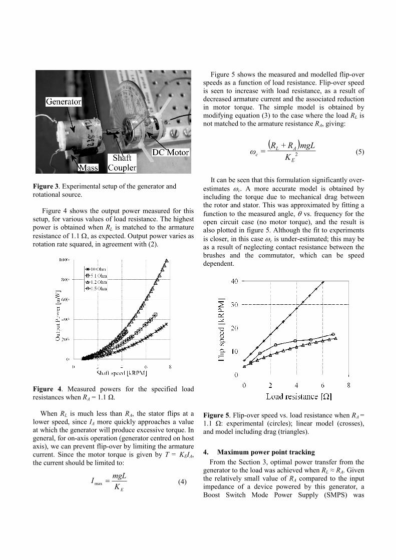
Figure 3. Experimental setup of the generator and
rotational source.
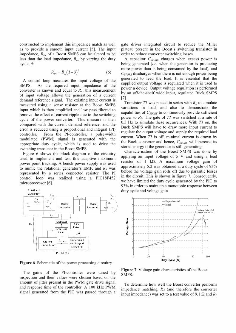
Figure 4 shows the output power measured for this
setup, for various values of load resistance. The highest
power is obtained when RL is matched to the armature
resistance of 1.1 Ω, as expected. Output power varies as
rotation rate squared, in agreement with (2).
Figure 4. Measured powers for the specified load
resistances when RA = 1.1 Ω.
When RL is much less than RA, the stator flips at a
lower speed, since IA more quickly approaches a value
at which the generator will produce excessive torque. In
general, for on-axis operation (generator centred on host
axis), we can prevent flip-over by limiting the armature
current. Since the motor torque is given by T = KEIA,
the current should be limited to:
EK
mgLI =max
(4)
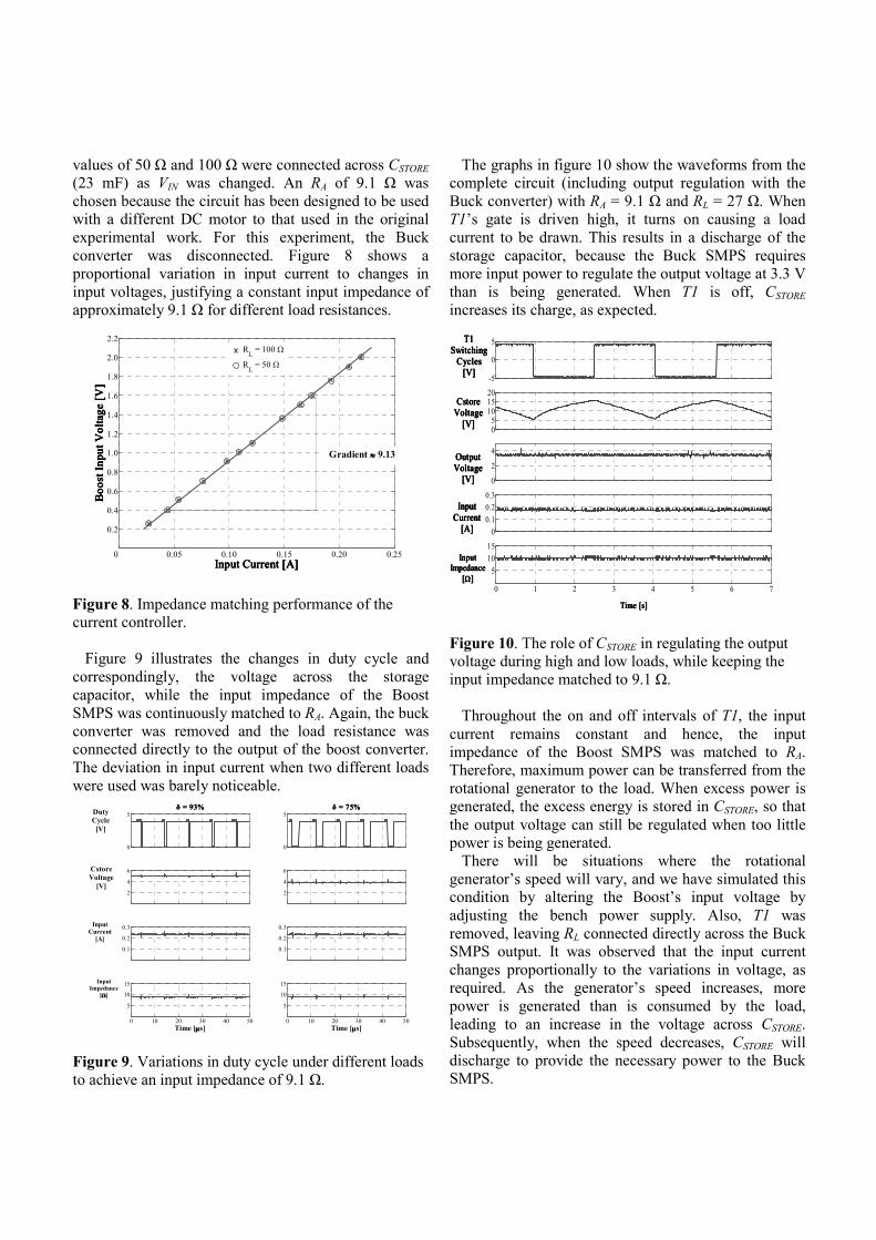
Figure 5 shows the measured and modelled flip-over
speeds as a function of load resistance. Flip-over speed
is seen to increase with load resistance, as a result of
decreased armature current and the associated reduction
in motor torque. The simple model is obtained by
modifying equation (3) to the case where the load RL is
not matched to the armature resistance RA, giving:
( )
2
+=
E
AL
c K
mgLRRω (5)
It can be seen that this formulation significantly over-
estimates ωc. A more accurate model is obtained by
including the torque due to mechanical drag between
the rotor and stator. This was approximated by fitting a
function to the measured angle, θ vs. frequency for the
open circuit case (no motor torque), and the result is
also plotted in figure 5. Although the fit to experiments
is closer, in this case ωc is under-estimated; this may be
as a result of neglecting contact resistance between the
brushes and the commutator, which can be speed
dependent.
Figure 5. Flip-over speed vs. load resistance when RA =
1.1 Ω: experimental (circles); linear model (crosses),
and model including drag (triangles).
4. Maximum power point tracking
From the Section 3, optimal power transfer from the
generator to the load was achieved when RL ≈ RA. Given
the relatively small value of RA compared to the input
impedance of a device powered by this generator, a
Boost Switch Mode Power Supply (SMPS) was
constructed to implement this impedance match as well
as to provide a smooth input current [5]. The input
impedance, RIN of a Boost SMPS can be altered to be
less than the load impedance, RL, by varying the duty
cycle, δ:
( )2
IN LR R 1 δ= − (6)
A control loop measures the input voltage of the
SMPS. As the required input impedance of the
converter is known and equal to RA, this measurement
of input voltage allows the generation of a current
demand reference signal. The existing input current is
measured using a sense resistor at the Boost SMPS
input which is then amplified and low pass filtered to
remove the effect of current ripple due to the switching
cycle of the power converter. This measure is then
compared with the current demand reference, and the
error is reduced using a proportional and integral (PI)
controller. From the PI-controller, a pulse-width
modulated (PWM) signal is generated with the
appropriate duty cycle, which is used to drive the
switching transistor in the Boost SMPS.
Figure 6 shows the block diagram of the circuitry
used to implement and test this adaptive maximum
power point tracking. A bench power supply was used
to mimic the rotational generator’s EMF, and RA was
represented by a series connected resistor. The PI
control loop was realized using a PIC18F452
microprocessor [6].
Figure 6. Schematic of the power processing circuitry.
The gains of the PI-controller were tuned by
inspection and their values were chosen based on the
amount of jitter present in the PWM gate drive signal
and response time of the controller. A 100 kHz PWM
signal generated from the PIC was passed through a
gate driver integrated circuit to reduce the Miller
plateau present in the Boost’s switching transistor in
order to reduce converter switching losses.
A capacitor CSTORE charges when excess power is
being generated (i.e. when the generator is producing
more power than is being consumed by the load), and
CSTORE discharges when there is not enough power being
generated to feed the load. It is essential that the
supplied output voltage is regulated when it is used to
power a device. Output voltage regulation is performed
by an off-the-shelf wide input, regulated Buck SMPS
[7].
Transistor T1 was placed in series with RL to simulate
variations in load, and also to demonstrate the
capabilities of CSTORE to continuously provide sufficient
power to RL. The gate of T1 was switched at a rate of
0.3 Hz to simulate these occurrences. With T1 on, the
Buck SMPS will have to draw more input current to
regulate the output voltage and supply the required load
current. When T1 is off, minimal current is drawn by
the Buck converter and hence, CSTORE will increase its
stored energy if the generator is still generating.
Characterisation of the Boost SMPS was done by
applying an input voltage of 5 V and using a load
resistor of 1 kΩ. A maximum voltage gain of
approximately 5.2 was obtained at a duty cycle of 93%
before the voltage gain rolls off due to parasitic losses
in the circuit. This is shown in figure 7. Consequently,
we have limited the duty cycle generated by the PIC to
93% in order to maintain a monotonic response between
duty cycle and voltage gain.
0 20 40 60 80 100
1
2
3
4
5
6
7
8
Duty Cycle [%]Duty Cycle [%]Duty Cycle [%]Duty Cycle [%]
Voltag
e G
ain
Voltag
e G
ain
Voltag
e G
ain
Voltag
e G
ain
Experimental
Ideal
Voltage Gain = 5.2
Duty Cycle = 93%
Figure 7. Voltage gain characteristics of the Boost
SMPS.
To determine how well the Boost converter performs
impedance matching, RA (and therefore the converter
input impedance) was set to a test value of 9.1 Ω and RL
values of 50 Ω and 100 Ω were connected across CSTORE
(23 mF) as VIN was changed. An RA of 9.1 Ω was
chosen because the circuit has been designed to be used
with a different DC motor to that used in the original
experimental work. For this experiment, the Buck
converter was disconnected. Figure 8 shows a
proportional variation in input current to changes in
input voltages, justifying a constant input impedance of
approximately 9.1 Ω for different load resistances.
0 0.05 0.10 0.15 0.20 0.25
0.2
0.4
0.6
0.8
1.0
1.2
1.4
1.6
1.8
2.0
2.2
Input Current [A]Input Current [A]Input Current [A]Input Current [A]
Boost
Input V
oltag
e [V
]B
oost
Input V
oltag
e [V
]B
oost
Input V
oltag
e [V
]B
oost
Input V
oltag
e [V
]
RL = 100 Ω
RL = 50 Ω
Gradient ≈≈≈≈ 9.13
Figure 8. Impedance matching performance of the
current controller.
Figure 9 illustrates the changes in duty cycle and
correspondingly, the voltage across the storage
capacitor, while the input impedance of the Boost
SMPS was continuously matched to RA. Again, the buck
converter was removed and the load resistance was
connected directly to the output of the boost converter.
The deviation in input current when two different loads
were used was barely noticeable.
0
5
δδδδ = 75% = 75% = 75% = 75%
2
4
6
0.1
0.2
0.3
0 10 20 30 40 50
5
10
15
Time [µµµµs]
0
5
δδδδ = 93% = 93% = 93% = 93%
2
4
6
0.1
0.2
0.3
0 10 20 30 40 50
5
10
15
Time [µµµµs]
Cstore
Voltage
[V]
InputCurrent
[A]
Input
Impedance
[ΩΩΩΩ]
Duty
Cycle
[V]
Figure 9. Variations in duty cycle under different loads
to achieve an input impedance of 9.1 Ω.
The graphs in figure 10 show the waveforms from the
complete circuit (including output regulation with the
Buck converter) with RA = 9.1 Ω and RL = 27 Ω. When
T1’s gate is driven high, it turns on causing a load
current to be drawn. This results in a discharge of the
storage capacitor, because the Buck SMPS requires
more input power to regulate the output voltage at 3.3 V
than is being generated. When T1 is off, CSTORE
increases its charge, as expected.
-5
0
5
05
101520
0
2
4
0
0.1
0.2
0.3
0 1 2 3 4 5 6 7
5
10
15
Time [s]Time [s]Time [s]Time [s]
InputInputInputInput
ImpedanceImpedanceImpedanceImpedance
[[[[ΩΩΩΩ]]]]
InputInputInputInput
CurrentCurrentCurrentCurrent[A][A][A][A]
OutputOutputOutputOutputVoltageVoltageVoltageVoltage
[V][V][V][V]
CstoreCstoreCstoreCstoreVoltageVoltageVoltageVoltage
[V][V][V][V]
T1T1T1T1
SwitchingSwitchingSwitchingSwitchingCyclesCyclesCyclesCycles
[V][V][V][V]
Figure 10. The role of CSTORE in regulating the output
voltage during high and low loads, while keeping the
input impedance matched to 9.1 Ω.
Throughout the on and off intervals of T1, the input
current remains constant and hence, the input
impedance of the Boost SMPS was matched to RA.
Therefore, maximum power can be transferred from the
rotational generator to the load. When excess power is
generated, the excess energy is stored in CSTORE, so that
the output voltage can still be regulated when too little
power is being generated.
There will be situations where the rotational
generator’s speed will vary, and we have simulated this
condition by altering the Boost’s input voltage by
adjusting the bench power supply. Also, T1 was
removed, leaving RL connected directly across the Buck
SMPS output. It was observed that the input current
changes proportionally to the variations in voltage, as
required. As the generator’s speed increases, more
power is generated than is consumed by the load,
leading to an increase in the voltage across CSTORE.
Subsequently, when the speed decreases, CSTORE will
discharge to provide the necessary power to the Buck
SMPS.

From the plots in figure 11, it can be seen that the
output voltage stays regulated at 3.3 V and, as
importantly, the input impedance stays matched to RA –
an essential condition for harvesting energy optimally
from a rotational source in practical situations.
It should be noted that the end-to-end efficiency of the
power processing circuit has not yet been evaluated, or
optimized. However, this circuit does serve as a proof-
of-concept for, and first demonstration of, maximum
power point tracking for a motion energy harvesting
generator.
02468
0
0.2
0.4
0.6
0
5
10
15
0
5
10
15
0 5 10 15 20 25 30 35 40 45 50
2
4
Time [s]Time [s]Time [s]Time [s]
BoostBoostBoostBoost
InputInputInputInput
VoltageVoltageVoltageVoltage[V][V][V][V]
InputInputInputInput
CurrentCurrentCurrentCurrent
[A][A][A][A]
InputInputInputInput
ImpedanceImpedanceImpedanceImpedance
[[[[ΩΩΩΩ]]]]
CstoreCstoreCstoreCstore
VoltageVoltageVoltageVoltage
[V][V][V][V]
OutputOutputOutputOutput
VoltageVoltageVoltageVoltage
[V][V][V][V]
Figure 11. Performance of the matching circuit for a
varying input voltage and fixed load, showing that the
input impedance remains matched to RA.
5. Off-axis operation
Whilst there are applications in which this energy
harvester could be used with its centre of rotation
aligned with the centre of rotation of the host, it will
often be useful, and in some instances essential, to
attach the harvester off-axis. This is illustrated in figure
12.
If the centres of rotation are misaligned (increasing
l1), the entire generator is subjected to a centripetal
force. This has the effect of causing the offset mass, m,
to be thrown outwards and thus the rate of change of
(θ1 − θ2) reduces. As it is this rate of change that causes
power to be generated, the offset position of the
generator will tend to reduce the power generated.
Figure 12. Schematic of the off-axis generator.
As shown in figure 12, this mechanical problem is
essentially that of the double pendulum, where the first
link is driven at constant rotational speed, i.e. 1θ& is
constant. The equation of motion describing the rotation
of the mass, m, through the angle θ2 can be derived as:
( ) ( ) ( )
( )
A
E
Rlm
K
l
gll
2
2
12
2
2
2211121211
2
2
sincossin
θθ
θθθθθθθθ
&&
&&&&&
−−
−−−−=
(7)
This is the well-known equation of motion for a
double pendulum, with an additional term representing
the damping due to the generator as described in section
2. Analytical solutions to the motion of the double
pendulum system are not possible even when 1θ& is
constant, as the system is non-linear and chaotic, and so
in order to determine the importance of this centripetal
effect on power generation, a Simulink model of a
double pendulum system was built to investigate the
behaviour numerically. This model implements
equation (7), with the values of the physical parameters
being taken from those of the generator used in the
experimental work, assuming a matched load resistance.
The host speed is linearly increased from zero to 50
rad.s-1 (about 500 rpm).
With no non-linear effect (i.e. l1 = 0), the system is
expected to generate power proportional to the square
of rotational angular velocity. This behaviour is
confirmed by simulation, and is illustrated by the
smooth line in figure 13. Figure 13 also shows the
instantaneous power (after moderate low pass filtering
to reduce the most rapid oscillations), for two non-zero
values of offset distance. The host speed is linearly
increased from zero to 50 rad.s-1. As can be seen, the

power initially rises as in the on-axis case, but with
oscillations of increasing magnitude. For the larger
offset, the centripetal acceleration eventually
overwhelms the gravitational effect, and the power
begins to drop.
0 10 20 30 40 50 60 70 80 90 1000
2
4
6
8
10
12
14
Time [s]
Pow
er [m
W]
L1 = 0.1 m
L1 = 0.02 m
L1 = 0 m
Figure 13. Generated power vs. time as host rotation
rate is ramped linearly from 0 to 50 rad.s-1, for offset
distances l1 as indicated.
A much lower speed range was chosen for figure 13
than for the experimental (on-axis) values of figure 4,
because of the low flip-over speeds at higher offsets.
However, the on-axis simulation in figure 13 (L1 = 0)
agrees well with the matched load line of figure 4.
This behaviour is further illustrated in figure 14,
where the relative angular position of the harvester is
plotted for l1 = 10 cm. Initially this angle rises rapidly,
since the rotor is rotating with the source while the
stator undergoes only small oscillations. At some speed,
the stator flips over several times, but then stops, and
this happens several times. Eventually, the motion of
the stator is almost synchronized with the rotor, so that
only small, and decreasing, oscillations in the relative
angle are seen, corresponding to a decline in power. For
the smaller offset l1 = 2 cm, the stator remains held in
place by gravitational torque, so that the generated
power continues to rise. In general, for large offset
distances, we can expect a maximum rotational speed
beyond which the achievable output power drops
rapidly.
0 20 40 60 80 100
20
40
60
80
100
Time [s]Time [s]Time [s]Time [s]
θθ θθ11 11 -
-
-
- θθ θθ
22 22 [ [ [ [°° °° ]] ]]
Figure 14. Relative angle, (θ1 - θ2) for l1 = 10 cm.
6. Scaling considerations
In our experiments to date we have used cm-scale,
commercial DC motors for mechanical-to-electrical
power conversion. These devices can deliver more
power than would be required for many sensor
applications, and are also relatively bulky (volume
approximately 23 cm3). It is therefore of interest to
consider how the rotational energy harvesting generator
presented in this paper might be miniaturized, for
example through the use of MEMS technology.
From basic scaling considerations it can be shown
that the constant KE of a permanent magnet (PM)
generator scales as L2 where L is a characteristic length
[8]. This assumes that the device geometry and PM
magnetization remain constant as the device size is
changed. Under the same conditions, the armature
resistance RA scales as L-1. From these scaling laws it
follows that the available output power, as given by (2),
will scale as L5 at constant rotational speed, or as vol
5/3
where vol is the device volume.
The rapid scaling of the output power with size
precludes significant down-sizing of PM generators.
However, it is reasonable to expect that optimized mm-
scale generators should be capable of delivering useful
levels of power at modest rotation speeds, and this
potential has already been demonstrated by several
groups [9]. For example, a team at Laboratoire
d’Electronique de Grenoble (LEG) has recently
reported a MEMS axial-flux PM generator with an
active volume of only 23 mm3 that would be expected
to deliver around 850 µW if operated at 5000 rpm [10].
Figure 15 shows one possible implementation of a
rotational energy harvester based on an axial-flux PM
generator. The PM generator in this example is similar

in construction to one demonstrated previously by us
[8]. It comprises a rotor with embedded permanent
magnets sandwiched between two silicon stators
carrying electroplated copper coils. An eccentrically
mounted mass has been added to the rotor to allow
operation as a rotational energy harvesting generator.
Successful realization of an efficient MEMS-based
rotational energy harvester along the lines of figure 15
would require the implementation of suitable low-loss
bearings. Also, the power conditioning electronics
would need to be designed for efficient operation at low
generator output voltages. The scaling of KE is such that
mm-scale PM generators commonly have voltages in
the mV range at modest rotational speeds. For example,
the device reported by us in [8] had a KE of 1.34 x 10⁻⁴
V·s/rad, corresponding to an output voltage of 70 mV
rms at 5000 rpm.
Figure 15. Possible MEMS implementation of
microgenerator with integrated electronics.
7. Conclusions
The use of conventional DC machines for energy
harvesting from continuous rotation has been
demonstrated. The use of gravitational torque
substitutes for the inertial effect which is typically used
in energy harvesters, but cannot be used with
continuous motion. We have also designed and
demonstrated an adaptive power conditioning circuit,
which implements maximum power point tracking.
Finally, the use of the device when mounted off axis is
evaluated, and shown to be possible within a limited
range of source speed.
References
[1] J. A. Paradiso and T. Starner, Energy Scavenging
for Mobile and Wireless Electronics, Pervasive
Computing, IEEE, vol. 4, pp. 18-27, 2005.
[2] P. D. Mitcheson, T. C. Green, E. M. Yeatman, A.
S. Holmes, Architectures for Vibration-Driven
Micropower Generators, J. Microelectro-
mechanical Systems, vol. 13, pp. 429-440, 2004.
[3] E.M. Yeatman, Energy Harvesting from Motion
Using Rotating and Gyroscopic Proof Masses, J.
Mechanical Engineering Science 222 (C1), pp.
27-36 (2008).
[4] M. Hayakawa, Electric Wristwatch with
Generator, U.S. Patent 5,001,685, March, 1991.
[5] Tzern T. Toh, Paul D. Mitcheson, Eric M.
Yeatman, A Gravitational Torque Micro-
Generator For Self-Powered Sensing, in Micro
Mechanics Europe ’07, Guimarães, September
16-18, 2007, pp. 341-344.
[6] Microchip, http://www.microchip.com.
[7] Recom International Power, http://www.recom-
international.com.
[8] A. S. Holmes, G. Hong, K. R. Pullen, Axial-Flux,
Permanent Magnet Machines for Micropower
Generation, J. Microelectromechanical. Systems,
vol. 14, pp. 54-62, 2005.
[9] D.P. Arnold, Review of microscale magnetic
power generation, IEEE Trans. Mag., vol. 43, no.
11, pp. 3940-3951, 2007.
[10] H. Raisigel, O. Cugat, J. Delamare, Permanent
magnet planar micro-generators, Sens. Act. A,
vol. 130-131, pp. 438-444, 2006.